particle-size-grouping model of precipitation ... - …ccc.illinois.edu/s/reports10/xu_k...
TRANSCRIPT

Particle-Size-Grouping Model of Precipitation Kinetics in Microalloyed Steels
Kun Xu, Brian G. Thomas
Mechanical Science and Engineering Department
University of Illinois at Urbana-Champaign
1206 West Green St., Urbana, IL 61801, USA
Phone – (217) 333-6919
Fax – (217) 244-6534
Email: [email protected], [email protected]
Abstract: The formation, growth, and size distribution of precipitates greatly affects the
microstructure and properties of microalloyed steels. The computational Particle-Size-Grouping (PSG)
kinetic models were developed to simulate precipitate particle growth due to collision and diffusion
mechanisms. Firstly, the standard PSG method for collision is clearly explained and verified. Then a
new PSG method is proposed for the diffusion-controlled precipitate growth with complete mass
conservation. In comparison with the original population calculation, the PSG method saves
significant computation and preserves enough accuracy for system with a large range of particle sizes.
Finally the new PSG method is applied to simulate the precipitated fraction of AlN, and size
distribution of NbC during isothermal ageing processing, and good matches are found with
experimental measurements.
1. Introduction
The demand for steels with higher strength, ductility, and toughness is always increasing. Many
alloying additions act to improve these properties through the formation of precipitate particles. In
addition to the precipitation strengthening, the precipitates often act by pinning grain boundaries and
inhibiting grain growth during steel processes. This effect arises from the disappearance of a small
area of grain boundary when it intersects a second phase particle, and is widely acknowledged to
depend on the volume fraction and particle size of the precipitates[1-4]. Many small particles are more
effective than a few large particles. An unfortunate side effect is a decrease in high temperature
ductility and possible crack formation during processes such as casting and hot rolling due to the
growth of voids around precipitate particles on the weak grain boundaries. It is therefore important to
control the spatial distribution, morphological characteristics, and size distribution of precipitates
during all stages of steel processing. These parameters are generally determined by the alloy
composition, and temperature history. In high-deformation processes such as rolling, they also
strongly depend upon strain and strain rate.

The accurate modeling of precipitate growth has at least two analysis steps: 1) supersaturation, based
on equilibrium precipitation thermodynamics, 2) kinetic effects. Many models to predict equilibrium
precipitation are available in commercial packages based on minimizing Gibbs free energy, including
Thermo calc[5,6], FactSage[7], ChemSage[8], JMatPro[9], other CALPHAD models[10,11], and other
thermodynamic models based on solubility products in previous literature[12-16]. A recent equilibrium
model efficiently predicts the stable formation of typical oxides, sulfides, nitrides and carbides in
microalloyed steels, by solving the fully-coupled nonlinear system of solubility-product equations [17].
Mutual solubility is incorporated for appropriate precipitates with similar crystal structures and lattice
parameters. This model includes the solubility limit of precipitates in different steel phases, influence
of Wagner interaction on activities and complete mass conservation of alloying elements during
precipitation. The model has been widely validated with analytical solutions of simple cases, results
of a commercial package, and previous experimental results [17]. A useful equilibrium model must
accurately predict the occurrence and stability of precipitates, their equilibrium amounts, and
compositions, for different steel compositions, phases, and temperatures, in order to calculate the
supersaturation/driving force for a kinetic model.
Theoretically, precipitates start to form when the solubility limit is exceeded, but reaching
equilibrium usually takes a long time. For most steel processes, especially at lower temperatures,
equilibrium is seldom approached due to limited time. Thus, kinetic models of precipitate growth are
a practical necessity for realistic predictions.
An early effort to predict phase transformation kinetics is the KJMA model, by Kolmogorov[18],
Johnson, Mehl[19] and Avrami[20], which is widely used to study precipitation processes and to
generate TTT diagrams. The general isothermal KJMA equation to describe transformed fraction, f,
as a function of time, t, is given by[21]
( ) 1 exp( )nf t K t= − − ⋅ [1]
where K is the rate function for nucleation and growth which depends on chemical composition and
temperature, and n is the Avrami exponent typically ranging from 1-4, which depends on growth
dimensionality (1-D, 2-D or 3-D), nucleation index (zero, decreasing, constant or increasing
nucleation rate), and growth index (interface-controlled or diffusion-controlled). The parameters K
and n are determined from experimental measurements at different test temperatures and compositions,
and often vary during precipitation. Although this model was successfully applied to match some
precipitated fraction measurements[22,23], its empirical nature prevents it from describing alternate
thermomechanical processes without refitting the empirical parameters with further measurements.
Moreover, size distributions are not predicted with this model.
Precipitates can form at different stages and locations in steelmaking, including: in the liquid steel
due to collision, the mushy-zone between dendrites due to rapid diffusion during solidification, and on

the grain boundaries or inside the grains due to slow solid-state diffusion. This results in different
composition, morphology and size distribution of precipitates, thus greatly influences the steel product
qualities. Precipitate particles grow via two major mechanisms: 1) collision in liquid steel, 2)
diffusion in both liquid and solid steel. Both mechanisms have been studied extensively, and better
computational models are now available with fast improved computer power in recent decades.
Collisions between particles and rapid diffusion in the liquid phase increases the number of large
particles, and enhances inclusion removal by flotation. The evolution of particle concentration and
size distribution due to collisions has been described by the collision frequency between particles per
unit volume of liquid medium[24], and such models have been successfully applied for various
collision mechanisms, including turbulent collision[25], Stokes collision[26], Brownian collision[27] and
gradient collision[28].
The entire diffusion-controlled precipitation process in solid typically includes nucleation, growth
and coarsening stages. The nucleation stage includes an induction period to form stable nuclei,
followed by steady-state nucleation, where the number of new particles increases linearly with time[29].
Such a classical nucleation model[29] has been successfully applied to predict the start of strain-
induced Ti(C,N) precipitation in austenite[30], and the results agree well with measurements inferred
from stress relaxation experiments[31].
After nucleation, particles of all sizes can grow due to the high supersaturation that defines the
growth stage. After the nucleation and growth stages, precipitates of various sizes are dispersed in the
matrix phase. Once the supersaturation has decreased to equilibrium (~1), the solute concentrations in
the matrix and at the particle/matrix interface are comparable and capillary effects become dominant,
causing coarsening or Ostwald ripening[32]. Governed by the minimization of the total surface energy,
coarsening is driven by the difference in concentration gradients near precipitate particles of different
sizes. The larger particles are surrounded by low concentration, so grow by diffusion from the high
concentration surrounding smaller particles, which are less stable and shrink. Thus, the net number
density of all particles now decreases with time.
Each of these three stages is dominated by different mechanisms, and particle size evolution follows
different laws. Coarsening increases with time according to the mean particle size cubed [33,34], which
is slower than the square relation during the growth stage[35]. More discussion is given elsewhere on
nucleation[36], growth[37] and coarsening[38] phenomena.
Although the above phenomena describing precipitation kinetics are well established, most models of
nucleation, growth and coarsening are empirical curve-fits, with separate calibration parameters for
each stage. Moreover, they required simplified conditions and calculate only the variation of mean
precipitate size with time. Little information on the size distribution can be obtained. But, different
precipitate size distributions can have very different pinning effects on grain growth, even with the
same mean size. Thus a fundamental model including all possible precipitation mechanisms is needed.

Molecule-based models such as Smoluchowski[24] for collision and Kampmann[39] for diffusion are
attractive because the particles agglomerate automatically and the few parameters are fundamental
physical constants themselves. Unfortunately, they encounter inevitable difficulties when they are
applied to simulate practical processes, where precipitate size ranges greatly from nucleii ~ 0.1nm to
coarsened particles larger than 100μm. Realistic particles range in size over at least 6 orders of
magnitude, and contain from 1 to 1018 single molecules. With such an overwhelming linear scale, it is
impossible to solve realistic problems using traditional models based on molecules.
Attempting to overcome this difficulty, the particle-size-group (PSG) method has been introduced
in several previous studies[45],? and has proven to be very effective in calculating the evolution of
particle size distributions for collision-coagulation growth over a large size range. Rather than track
each individual particle size, the main idea of this technique is to divide the entire particle size range
into a set of size classes, each with a specific mean size and size range. Careful attention is required
to formulate the equations to ensure mass conservation[45]. Several researchers have applied this PSG
method to simulate inclusion agglomeration in liquid steel due to collisions, coagulation and removal.
Such models have been applied to RH degassers[40], continuous casting tundishes[41,42] and ladle
refining[43,44]. To start these PSG models, an initial size distribution is still required, which can be
found from either experimental measurements or assumptions.
To make the PSG method more usable, Nakaoka et al.[46] used different volume ratios between
neighboring size groups, taking advantage of the exponential increase in sizes that accompany powers
of 2. This innovation allows modeling from single molecules to realistic particle sizes with only 30-
50 size groups. Particle collisions were modeled, considering both inter-group and intra-group
interactions, and numerical results agreed well with experimental agglomeration curves. However,
very little work has been done to apply the PSG method to diffusion, which is the dominant
mechanism for precipitate growth in many processes including steel casting and rolling. One study by
Zhang and Pluschkell[47], coupled both collision and diffusion into a PSG model, but intra-group
diffusion was not considered. Zhang[48] included a discrete-sectional technique by Gelbard[49] and
Wu[50] into the PSG model, but this weakens the efficiency of the method and the accuracy of the
treatment of diffusion and the insurance of mass conservation has not been verified. No previous
study has demonstrated accurate simulation of diffusion using a PSG model.
The purpose of the present study is to develop accurate PSG methods to simulate precipitate
growth due to both collision and diffusion mechanisms. The standard PSG method for collision
problem is developed first, and a new PSG method is created. Both methods are verified by
comparison with exact solutions of the primary population equations in test problems. The new PSG
method is shown to be a very time-efficient calculation with complete mass balance and high accuracy.
Finally, the new PSG method is applied to simulate several practical precipitation processes in solid
steels, and compared with experimental measurements.

2. Models of precipitate growth mechanisms
2.1 Particle collision
The population balance model for collision first suggested by Smoluchowski[24] is:
1
, ,1 1
1
2
ii
k i k k i k i i k kk k
dnn n n n
dt
− ∞
− −= =
= Φ − Φ [2]
where ni is the number of size i particles per unit volume, or “number density”, and Фi,j is the collision
kernel between size i and size j particles. The first term on the right-hand side generates size i
particles due to the collision of two smaller particles, and the second term decreases the number of
size i particles by their collision with particles of any size to become larger particles. The generation
term is halved to avoid counting collision pairs twice. However, when two particles generating size i
particles have same size, the generation term should not be halved because the collision pair is unique.
Moreover, the loss term should be doubly counted when size i particles collide with themselves. The
number of molecules composing the largest agglomerated particle must be a finite number iM in
numerical computation. Making these appropriate changes gives the following improved expression:
1
, , , ,1 1
1(1 ) (1 )
2
Miii
k i k k i k k i k i i k i k kk k
dnn n n n
dtδ δ
−
− − −= =
= + Φ − + Φ [3]
where δi,k is the Kronecker delta, δi,k=1 for i=k and δi,k=0 for i≠k.
When i=1, the population balance for dissolved single molecules simplifies to:
11 1, 1,
1
(1 )Mi
k k kk
dnn n
dtδ
=
= − + Φ [4]
Thus the number density of single molecules always decreases with collisions. Evaluating equations
[3]-[4] requires summing over and tracking every possible size from 1 to iM molecules, so is not
practical for realistic particle sizes. Results from these equations, however, comprise the exact
solution for collision test problems.
2.2 Particle diffusion
Kampmann[39] suggested the following diffusion-controlled model to treat the kinetics of nucleation,
growth and coarsening as one continuous and simultaneous process.
1 1 1 1 1 1 1 ( 2)ii i i i i i i i i i
dnn n n n A n A n i
dtβ β α α− − + + += − + − + ≥ [5]
where βi, αi and Ai are the diffusion growth rate, dissociation rate and reaction sphere surface area for
a size i particle containing i molecules. The first and second terms on the right-hand side account for
the loss and generation of size i particles due to “diffusion growth” by adding single molecules to

particle. The third and fourth terms account for the loss and generation of size i particles due to
particle “dissociation” from losing single molecules. The effects of equilibrium, diffusion growth,
curvature effects and mass balance are all included, with all the parameters having appropriate
physical significance.
For single molecules, i=1, the special cases of double loss when two molecules react with each other
and double generation of single molecules when size 2 particles dissociate are not counted exactly in
Kampmann’s initial work. Thus the following revised balance equation is suggested here:
11 1, 2,
1 2
(1 ) (1 )M Mi i
k k k k k k kk k
dnn n A n
dtδ β δ α
= == − + + + [6]
Assuming a uniform spherical concentration field of single molecules with a boundary layer
thickness of particle radius ri around each size i particle, the diffusion growth rate of size i particle is
expressed by[39]:
4i iDrβ π= [7]
where D is the diffusion coefficient in the matrix phase. As precipitation reactions always involve
more than one element, this coefficient is chosen for the slowest-diffusing element, which is assumed
to control the diffusion rate.
The following relation is assumed for the dissociation rate, which is the number of molecules lost
from the surface of size i particles per unit area per unit time, based on a mass balance of particles in
equilibrium with the surrounding matrix phase [39]:
1 /i i i in Aα β= [8]
The concentration of single molecules, 1in , in equilibrium around the surface of each particle is
needed to evaluate this equation. This is estimated using the Gibbs-Thompson equation, and
decreases with increasing particle size as follows[51]:
1 1,
2 1exp P
i eqg i
Vn n
R T r
σ =
[9]
where n1,eq is the number density of dissolved single molecules in equilibrium with a plane interface of
the precipitate phase, σ is the interfacial energy between the precipitate particles and the matrix phase,
VP is the molar volume of the precipitate, Rg is the gas constant, T is the temperature. and ri is the
radius of size i particles. This equation indicates that increasing particle radius causes the nearby
solute concentration to decrease greatly, by several orders of magnitude.
Results from equations [5]-[9] are considered to be the exact solution for diffusion test problems.
3. Particle-size-grouping (PSG) method

From a theoretical point of view, these models based on molecules in the previous section are
accurate and the integration of their set of governing equations is straight forward. However, the
computational cost quickly becomes infeasible for realistic particle sizes. The PSG method is
introduced here to overcome this difficulty. The fundamental concept of the PSG method is shown
schematically in Fig. 1. In this method, the particles are divided into different size groups (size group
number j) with characteristic volumes Vj and characteristic radius rj. The number density of particles
of size group j is defined as
, 1 1,
( )j j j j
jV V V
N n V+ −> >
= [10]
This summation covers all particles whose volume lies between two threshold values. The threshold
volume that separates two neighboring size groups, Vj,j+1, is assumed to be the geometric average of
the characteristic volumes of these two groups, instead of the arithmetic average used in previous
works[46,47]:
, 1 1j j j jV V V+ += [11]
If a newly generated particle has its volume between Vj-1,j and Vj,j+1, it is counted in size group j.
The increase of number density of size group j is then adjusted according to the difference between the
volume of the new particle and Vj, in order to conserve mass.
The particle volume ratio between two neighboring size groups is defined as
1jV
j
VR
V+= [12]
In general, RV need not be a constant. However, for constant RV, the above variables simplify as
11
jj VV R V−= , ( 1/ 2)
, 1 1j
j j VV R V−+ = [13]
where the volume of a single molecule, V1, is computed using the molar volume of its precipitate
crystal structure, VP:
1P
A
VV
N= [14]
where NA is Avogadro number, and the small effects of temperature change and vacancies are
neglected. Since this volume is calculated from a bulk property, VP, the packing factor is not needed.
The number of molecules contained in the given volume is
1
jj
Vm
V= ,
, 1, 1
1
j jj j
Vm
V+
+ = [15]
In the PSG method, it is easy to introduce fractal theory to consider the effect of particle morphology.
The effective radius of a particle can be expressed by

1/
11
fD
jj
Vr r
V
=
[16]
where Df is the fractal dimension, which can vary from 1 (needle-shaped precipitates) to 3 (complete
coalescence). Tozawa[52] proposed Df=1.8 for Al2O3 clusters in liquid steel, and Df=3 is adopted in
this work for simplicity.
After the number of single molecules composing the largest agglomerated particles iM is determined,
the corresponding number of size groups GM chosen for the PSG method to cover the complete size
range must satisfy 1MGV MR i− > . Thus GM must satisfy:
(log ) 1 1VM R MG ceil i≥ + + [17]
The largest size group is a boundary group which always has zero number density. The accuracy of
the PSG method is expected to increase with smaller value of RV since more size groups are used.
From the logarithm relation shown above, the PSG method is far more efficient for real problems with
a large range of particle sizes.
3.1 PSG method for collision
The following assumptions are made: a collision of size group j particle with smaller particle ranging
from size group 1 to kc,j still generates size group j particle with size larger than Vj, and a collision of
size group j particle with particle larger than size group kc,j generates particle in j+1 or higher size
group. Moreover, a collision of size group j-1 particle with the particle ranging from size group kc,j to
j-1 generates size group j particle. The corresponding coefficients are inserted before each term so as
to conserve the volume. Consider all these assumptions to get the equation
,
, ,
11
, , , 1, 11 1
(1 ) ( 2)c j M
c j c j
k G jj j kk
j j k k j j k j k k j k j kk k k k kj j
dN V VVN N N N N N j
dt V Vδ
−−
− −= = + =
+ = Φ − + Φ + Φ ≥
with ,
1 4.000 2.148
2 2.148 1.755
3 1.755 1.587
V
c j V
V
j R
k j R
j R
− > >= − > > − > >
[18]
The above values are given by solving the equations
, 1 , 1c jj k j jV V V+ ++ > [19]
k≤kc, →+j j k>kc,j →+j m>j
j-1≥k≥kc,j
k →+j-1 j
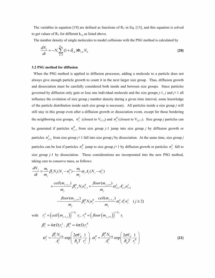
The variables in equation [19] are defined as functions of RV in Eq. [13], and this equation is solved
to get values of RV for different kc,j as listed above.
The number density of single molecules to model collisions with the PSG method is calculated by
11 1, 1,
1
(1 )MG
k k kk
dNN N
dtδ
=
= − + Φ [20]
3.2 PSG method for diffusion
When the PSG method is applied to diffusion processes, adding a molecule to a particle does not
always give enough particle growth to count it in the next larger size group. Thus, diffusion growth
and dissociation must be carefully considered both inside and between size groups. Since particles
governed by diffusion only gain or lose one individual molecule and the size groups j-1, j and j+1 all
influence the evolution of size group j number density during a given time interval, some knowledge
of the particle distribution inside each size group is necessary. All particles inside a size group j will
still stay in this group even after a diffusion growth or dissociation event, except for those bordering
the neighboring size groups, Ljn (closest to Vj-1,j) and R
jn (closest to Vj,j+1). Size group j particles can
be generated if particles 1Rjn − from size group j-1 jump into size group j by diffusion growth or
particles 1Ljn + from size group j+1 fall into size group j by dissociation. At the same time, size group j
particles can be lost if particles Rjn jump to size group j+1 by diffusion growth or particles L
jn fall to
size group j-1 by dissociation. These considerations are incorporated into the new PSG method,
taking care to conserve mass, as follows:
1 11( ) ( )j R L
j j j j j j jj j
dN m mN N n A N n
dt m mβ α= − − −
1, , 1
1 1 1 1 1 1
( ) ( )j j j jR R L L Lj j j j j
j j
ceil m floor mN n A n
m mβ α− +
− − + + ++ +
, 1 1,
1
( ) ( )( 2)j j j jR R L L L
j j j j jj j
floor m ceil mN n A n j
m mβ α+ −− − ≥
with ( )( )1/
1, 1
fDLj j jr ceil m r−= , ( )( )1/
, 1 1
fDRj j jr floor m r+=
14L Lj jD rβ π= , 14R R
j jD rβ π=
1, 2 1
expLj eqL P
j L Lj g j
N V
A R T r
β σα
=
, 1, 2 1
expRj eqR P
j R Rj g j
N V
A R T r
β σα
=
[21]

where Ljn is the number density of those particles in size group j which fall into size group j-1 by
losing one molecule, and Rjn is the number density of those particles in size group j which jump into
size group j+1 by gaining one molecule. Function ceil calculates the smallest integer which is not less
than the given real number, and floor for the largest integer which is not larger than the given real
number. The corresponding radius, diffusion growth rate and dissociation rate are also calculated for
these particles. Since the mean and boundary (ceil, floor) values of size groups are utilized directly
and RV is not explicitly shown in equation, this formulation is very flexible to apply. This allows
arbitrary size increment between groups, making it easy to improve accuracy with smaller RV and
improve computation with larger RV in single simulation. The finer size groups need to be applied for
the main size range of interest, and the group sizes could be chosen to fit the experiments.
In the above equation, the first and second terms on the right-hand side account for the diffusion
growth and dissociation inside size group j, and third and fourth terms for generation of size group j
particles by the inter-group diffusion growth and dissociation. The last two terms are for loss of size
group j particles due to the diffusion growth and dissociation of size group j particles themselves.
For the diffusion population of single molecules in PSG method is given by
.11 1,
1 2
(1 ) ( ) ( )M MG G
R Lk k k k k k k k
k k
dNN N n A N n
dtδ β α
= =
= − + − + −
1 1, 2,1 2
(1 ) (1 )M MG G
R R L L Lk k k k k k k
k k
N n A nδ β δ α= =
− + + + [22]
The particle number densities Ljn and R
jn are estimated from geometric progression approximation
1, 1
1
( )
11
j j j
j j
ceil m mC m mjL C
j j Cj
nn n
n
− −
−
−−
−−
=
,
, 1
1
( )
1
j j j
j j
floor m mC m mjR C
j j Cj
nn n
n
+
+
−−
+ =
[23]
In order to propagate particle growth, if 0Ljn ≠ and 1 0C
jn + = , Rjn is calculated by
, 1
1
( )j j j
j j
floor m mC m mjR L
j j Lj
nn n
n
+
+
−−
=
[24]
The particle number density at center of each size group is calculated by assuming two geometric
progressions inside the size group j such that
1, , 1( ) ( )
1 1(1/ ) 1 ( )j j j j j j
jCj km ceil m floor m mL R k
j jk k
Nn
q q− +− −
= =
=+ +

with 1
1
1
j jm mjL
jj
nq
n
−−
−
=
, 1
1
1j jm m
jRj
j
nq
n
+ −+
=
[25]
The average number density of size group j is calculated as
, 1 1,( ) ( ) 1
jj
j j j j
Nn
floor m ceil m+ −
=− +
[26]
4. Validation of new PSG method with test problems
4.1 Collision problem
Saffman[25] suggested a turbulent collision frequency in unit volume of liquid medium:
1/ 2 31.3 ( / ) ( )ij i ja r rε νΦ = + [27]
where ε is turbulent energy dissipation rate and ν is kinematic viscosity. The empirical coefficient
a was suggested by Higashitani[53] and it is assumed as a constant here. This model has been often
applied to study the inclusion agglomeration in the liquid steel and chosen as our test problem for
collision.
Choose the dimensionless forms for variables as
*0/i in n n= , * 1/ 2 3
1 01.3 ( / )t a r n tε ν= [28]
Here n0 and r1 are the initial number density and the radius of single molecules. The initial condition
is given by ni*=1 for i=1 and ni
*=0 for i>1. The size of largest agglomerated particle is iM=12000,
such that 0.05% accuracy in the total volume of particles is guaranteed up to t*=1. The boundary
condition is constantly zero number density for the largest agglomerated particle in exact solution or
for the largest size group in PSG method. Runge-Kutta-Gill method is applied for integration and the
time step is selected as Δt*=0.0025 for accuracy, which is tested by comparing the results from smaller
step size and negligible difference is found.
Total dimensionless number density of molecules and particles are defined as
* *
1
Mi
M ii
N i n=
= ⋅ , * *
1
Mi
T ii
N n=
= for exact solution
* *
1
MG
M j jj
N V N=
= ⋅ , * *
1
MG
T jj
N N=
= for PSG method [29]
The mass balance requires NM* to be constant in the whole calculation. In Fig. 2, we could see the
total volume of particles is conserved for both exact solution and PSG method. There is also good
agreement for total number density of particles for both cases of RV=3 and RV=2. Fig. 3 shows that
the change of the number densities of each size group with time and the PSG method also agrees well

with the exact solution for different RV. For size group N10 in RV=2, it contains all of the particle sizes
ranging from 363 to 724 molecules, with a central size of 512 molecules. When time increases,
collision always promotes large particles to form and small particles to disappear. With smaller value
of RV, the accuracy of PSG method increases as expected.
4.2 Diffusion problem
It is assumed the total number density of single molecules in system are produced by an isothermal
first order reaction[39]
* * * * *1,
1
( ) ( ) / 9[1 exp( 0.1 )]Mi
s s eq ii
n t n t n i n t=
= = ⋅ = − − [30]
Since ns* increases with time, the number density of dissolved single molecules must be adjusted
with the increase of ns* at each time step. It could be also explained as the supersaturation increase
when temperature drops in the practical cooling process.
The dimensionless forms are defined as
*1,/i i eqn n n= , *
1 1 1,4 eqt D r n tπ= [31]
Choose B=2σVP/(RgTr1)=3.488 for calculating dissociation rate. The initial condition is ni*=0 for i≥1.
The boundary condition is also zero number density for the largest agglomerated particle in exact
solution or for the largest size group in PSG method all the time. The maximum size of agglomerated
particle is chosen as iM=50000, such that mass conservation is guaranteed up to t*=10000. Runge-
Kutta-Gill method was also used for integration and the time step is selected as Δt*=0.01 for accuracy.
As shown in Fig. 4, the total volume of particles is conserved for both exact solution and PSG
method. Fig. 5 shows how the particle size distribution evolves due to the changing concentration
gradients near particles of different size groups. At early times, all size group particles grow owing to
the driving force of increasing supersaturation. At later times, the results show Ostwald ripening. The
large particles have low concentrations, so tend to grow at the expense of smaller particles, which
have high local concentrations, and eventually shrink. For example, size group N1 (dissolved single
molecules) reaches its peak and starts to decrease in number after t*=20. There are reasonable
agreements for total particle number density and number densities of each size group between the PSG
method and exact solution for both cases of RV=3 and RV=2. The PSG method for RV=2 matches
exact solution more closely.
The computation times of the above test problems are listed in Table I. All the calculations are run
with Matlab on Dell OPTIPLEX GX270 with P4 3.20GHz CPU and 2GB RAM in order for
comparison. The computational cost is found to dramatically reduce in PSG method. It is worth to
mention that the computation cost for collision problem is proportional to iM2 for exact solution or GM
2
for the PSG method, while proportional to iM or GM correspondingly for diffusion problem. Since the

details of particle distribution in size groups is calculated in diffusion problem, the time saving is not
so significant. But this is enough to make practical precipitation calculations possible, considering
that less than 60 size groups covers particle sizes up to 100μm with constant RV=2 for most nitrides
and carbides.
5. Practical applications
When the PSG method [21] is applied to model a real precipitation process, it becomes essential to
avoid stability problems due to dissociation exceeding diffusion growth. A stable scheme is required
to apply a large time step size in simulation to enable reasonable computation times. Thus the implicit
Euler scheme is adopted to integrate the equations through time:
, 1 1,1 111
( ) ( )1 ( )j j j jR i L L i
j j j j j jj j j
floor m ceil mmt A N A N
m m mα β α+ −+ +
+ Δ + +
1, , 11 1 11 11 1 1 1 1 1 1
( ) ( )( ) j j j ji i i R L R i R L L L
j j j j j j j j j j j jj j j j
ceil m floor mm mN t N N n A n N n A n
m m m mβ α β α− ++ + +
− − + + +
= + Δ − + + +
, 1 1,1 1 1
1
( ) ( )( ) ( ) ( 2)j j j jR i i R L L i L
j j j j j j jj j
floor m ceil mN N n A N n j
m mβ α+ −+ + +
+ − + − ≥
[32]
where i is the index of time step. The above system of equation is computed by iterative Gauss-Seidel
method until the largest change of 1ijN + converges to be less than 10-5 between two iterations. The
upper limits of Ljn and R
jn are 1ijN + , and the values of L
jn and Rjn are evaluated at each iteration.
Since the mass conservation is validated in test problems, the number density of single molecule is
then computed as follows, in order to save computation:
1 11
2
MGi i
s j jj
N n m N+ +
=
= − [33]
where ns is the total number density of molecules, which is determined by the steel composition. If
the steel composition of element M is M0, then the total number density of molecules in steel is
calculated as
0
100steel
s AM
Mn N
A
ρ= [34]
The equilibrium number density of single molecules in steel is calculated from its equilibrium
dissolved mass concentration [M], which is obtained from the equilibrium precipitation calculation
1,
[ ]
100steel
eq AM
Mn N
A
ρ= [35]

Where AM is the atomic mass of element M, and ρsteel is the density of steel matrix (7500kg·m-3).
Although the suggested scheme is stable for any time step size, the accuracy is maybe exacerbated if
the time step is too large. Thus the reasonable time step is chosen when small difference is found if the
time step continues to decrease.
5.1 Size distribution for isothermal NbC precipitation
In order to validate the ability of PSG model to simulate the size distribution of precipitate particle,
the experimental results from Jones and Howell[54] is extracted for comparison. The steel has a
composition of 20%Cr, 25%Ni, 0.5%Nb, 0.05%C+N. The case of the specimen solution treated at
1350oC, quenched and aged at 930oC for 1800s with no deformation prior to ageing is chosen to
compare with simulation. The carbon extraction replicas were used in the acquisition of quantitative
particle size distribution data. This technique is proved to be powerful to detect nuclei with the
diameter of less than 2nm[55]. The truncating radius is set as 0.31nm to match experiments.
Since the individual compositions of carbon and nitrogen are not clear, the total 0.05% composition
is assumed to be purely carbon in calculation because the alloying carbon in steel is always much
plentiful than nitrogen. Since it is sufficient to react with Nb, the number density of NbC particles is
calculated based on available carbon. Diffusion coefficient of Nb in austenite is taken as
DNb(m2/s)=0.83×10-4exp(-266500/RT)[56], molar volume of NbC is VP=13.39×10⁻⁶m3/mol[57]. The
value of interfacial energy is calculated in the appendix. The equilibrium calculation in Fig. 6 shows
that the NbC precipitate begins to form at 1310oC, and the equilibrium dissolved mass concentration
of carbon in steel is 0.0052426wt% at T=930oC. In order to compare with experimental data, RV is
not set as constant. RV=2 for particles with radius smaller than 3nm, 1nm size groups are used for 3-
15nm, 1.5nm size groups for 15-24nm, 3nm size groups for 24-36nm, 6nm size groups for 36-48nm.
Total 38 size groups are used to cover the particle size up to 48nm. Last size group must be set to
cover the largest observed particle formed in experiments. The time step is set as 0.001s with
maximum of iteration 10000 for convergence.
The measured particle size distribution/volume number frequency plot averaged over all of the matrix
regions is normalized and compared with simulation results in Fig. 7. The actual mean radius of NbC
particles were 9.3nm in experiment and 8.13nm in simulation and particle size distribution also
matches reasonably. It is also observed that the measured size distribution is wider than the simulation
results. The reason is that there are always large densities of grain boundaries and dislocations in
steels where easier nucleation and higher diffusion rate are possible to form larger precipitate particles.
Moreover, the uncertainty of carbon and nitrogen in the given steel composition will change the
precipitate type from NbC to Nb(C,N), thus influence the equilibrium dissolved concentration

(supersaturation) and the interfacial energy of precipitate particles. The formation of other precipitates
also can not be excluded, especially the chromium carbide and nitride due to the high concentration of
chromium. If these precipitates form earlier and become the nucleation sites of NbC, the precipitation
of NbC will be accelerated.
5.2 Precipitated fraction of isothermal AlN precipitation
The isothermal precipitation behavior for AlN in a 0.09%C, 0.20%Si, 0.36%Mn, 0.051%Al and
0.0073%N steel is measured by Vodopivec[58]. Specimens were first solution treated at 1300oC for 2
hours before being quenching to the precipitation temperature. The AlN content in steel was
determined by the Beeghly method[59]. Since it has been suggested that Beeghly technique is
insensitive to detect the presence of fine precipitate particles which could pass through the filter[60,61],
the truncating precipitate radius is set as 1.93nm in the simulation to match the measurements. The
initial experimental measurements all start from nonzero value, possible because the cooling stage
from solution treated temperature to precipitation temperature or the quenching stage after the
precipitation test is not quick enough. The final precipitated amounts of nitrogen in AlN at each
holding temperature could not reach their theoretical values calculated by equilibrium model, even
when the precipitated fraction become nearly constant under very long holding time. It is maybe
caused by the fact that other types of nitrides exist in steels. Thus the measurements are normalized
with zero fractions at beginning and maximum value (N0-[N])/N0 at the entire precipitation process.
Diffusion coefficient of Al in austenite is taken as DAl(m2/s)=2.51×10-4exp(-253400/RT)[62], molar
volume of AlN is VP=12.54×10⁻⁶m3/mol[57]. The interfacial energies are calculated by the method in
appendix. The number densities of precipitate particles are calculated by the nitrogen concentration
since it is insufficient when reacting with aluminum to form AlN. The experiments found that
precipitation was much quicker in ferrite phase because of lower solubility limit of AlN and quicker
diffusion rate of aluminum, the precipitation of AlN at 700oC is also simulated with the diffusion
coefficient of Al in ferrite DAl(m2/s)=0.3×10-2exp(-234500/RT)[57].
As shown in Fig. 6, the equilibrium model[17] calculated the formation temperature of AlN is 1236oC,
and the equilibrium dissolved concentration of nitrogen in steel is around 0.00022wt% at T=840oC
(ПC=33.2) and 0.0000031wt% at T=700oC (ПC=2370). A sharp decrease of equilibrium dissolved
aluminum concentration could be seen during γ→α phase transformation (within temperature range
865oC to 715oC) because of the solubility limit of AlN is much lower in ferrite, which is already
carefully considered in the equilibrium model. Constant RV=2 and total 32 size groups are used in the
simulation, and this covers particle radius up to around 200nm. The time step is set as 0.001s with
maximum of iteration 10000 for convergence.

The numerical results are shown and compared with experimental measurements in Fig. 8, and good
matches are found for precipitated AlN fractions at both isothermal annealing temperatures. The
calculation verifies the experimental observation of greatly accelerated precipitation in ferrite even at
a lower temperature. The calculated size distribution evolution of AlN particles at each annealing
temperature are depicted in Fig. 9. The results show that at 700oC, because of high supersaturation and
large diffusion rate, the diffusion growth stage finished within 90s, and the coarsening governs the
remaining precipitation process. The particle size distribution at 840oC shows that the coarsening
happens after 3100s since the increase of particle size becomes much slower after that. These
precipitate finish times correspond well with the transition points of precipitated fractions, which
changes from the sharp growth stage to the quite flat coarsening stage.
In this work, we do not introduce any fitting parameters in simulation, and the calculated particle size
distribution of NbC and precipitated amount of AlN corresponds well with experiments. The better
match could be obtained by more careful choice of involving physical parameters, such as equilibrium
dissolved concentration (supersaturation), diffusion rate or interfacial energy. It is also worth to
mention that the calculated results are deteriorated by the fact that there is always more than one type
of precipitate formed in steels. Since the different precipitates will possibly compete with each other
to attract the same elements, such as different nitrides attracting nitrogen, it is often not accurate to use
the steel composition to simulate growth of single precipitate unless the equilibrium model strictly
excludes the formation of other precipitates. The precipitates could form at different times in steels,
and the previously formed precipitates will be the nucleation sites for the new precipitates. Thus it
makes new precipitates nucleate and grow more easily, and the final property of multi-precipitates is
obviously different from that of two separate precipitates case. Such a multi-precipitate growth model
is maybe necessary in reality and being developed. Furthermore, the influence of deformation on
precipitation kinetics is also not considered in the current work, but it actually increases the nucleation
and growth rate of precipitation and cause a much finer particle size distribution[54,63]. These effects on
precipitation behaviors need to be discussed in our future work.
Conclusions:
1. A new general PSG method for particle collision has been derived for an arbitrary choice of size
ratio RV and good agreement has been verified with exact solutions.
2. A new, highly-efficient PSG method for diffusion-controlled particle growth has been developed.
Results match the exact solution of Kampmann within a reasonable tolerance. The method features
geometrically-based threshold values at the borders of each size group in order to accurately include
intra-group diffusion, corresponding accurate diffusion between size groups, and an efficient implicit
solution method to integrate the equations.
3. The new PSG method can simulate particle nucleation, growth, and coalesence due to collision and
diffusion over a wide size range or particles with low computational cost, high accuracy. Accuracy of
the method increases with decreasing RV as more size groups are used to cover the given particle size
range.
4. The computed size distributions of NbC and the precipitated fraction of AlN match reasonably with
previous experimental measurements in microalloyed steel without using any fitting parameters.
Precipitation in ferrite is found to be greatly accelerated due to the lower solubility limit and higher
diffusion rate of these precipitates in this phase.
5. The new PSG method is available to simulate realistic nonequilibrium precipitation behavior during
various steel processes, such as continuous casting, for arbitrary temperature histories. Future work
will incorporate other important effects into this kinetic model, such as multi-precipitate growth and
deformation-induced precipitation.
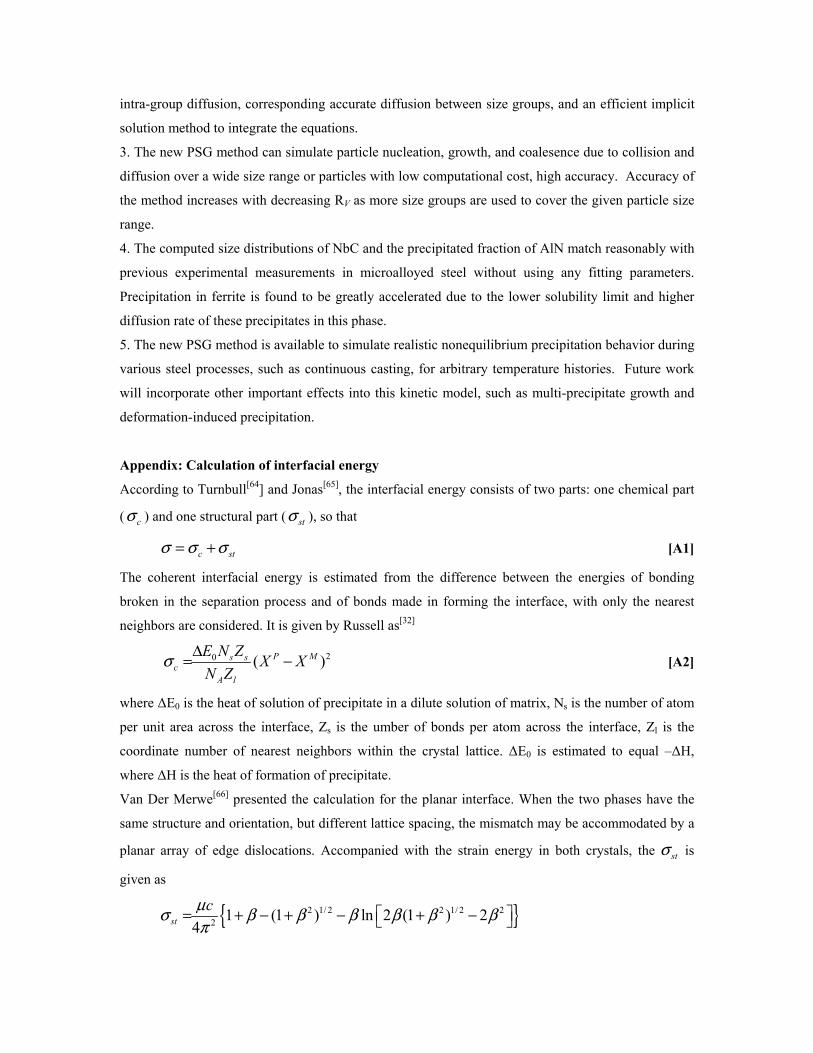
Appendix: Calculation of interfacial energy
According to Turnbull[64] and Jonas[65], the interfacial energy consists of two parts: one chemical part
( cσ ) and one structural part ( stσ ), so that
c stσ σ σ= + [A1]
The coherent interfacial energy is estimated from the difference between the energies of bonding
broken in the separation process and of bonds made in forming the interface, with only the nearest
neighbors are considered. It is given by Russell as[32]
20 ( )P Ms sc
A l
E N ZX X
N Zσ Δ= − [A2]
where ΔE0 is the heat of solution of precipitate in a dilute solution of matrix, Ns is the number of atom
per unit area across the interface, Zs is the umber of bonds per atom across the interface, Zl is the
coordinate number of nearest neighbors within the crystal lattice. ΔE0 is estimated to equal –ΔH,
where ΔH is the heat of formation of precipitate.
Van Der Merwe[66] presented the calculation for the planar interface. When the two phases have the
same structure and orientation, but different lattice spacing, the mismatch may be accommodated by a
planar array of edge dislocations. Accompanied with the strain energy in both crystals, the stσ is
given as
{ }2 1/ 2 2 1/ 2 22
1 (1 ) ln 2 (1 ) 24st
cμσ β β β β β βπ
= + − + − + −

with 2 1 1
e eM Pc a a
= + , 2 1 1
M Pμ μ μ= +
2λβ πδμ
+= , 2 e e
M P
e eM P
a a
a aδ
−=
+,
1 1 1M P
M P
ν νλ μ μ+
− −= + [A3]
where eMa and e
Pa are the effective nearest-neighbor distance across the interface, which are
estimated from the lattice parameters aM, aP and interface orientations. μM, μP and μ are shear modulus,
νM and νP are Poisson’s ratio. The subscript M, P and no subscript stand for the properties of matrix
phase, precipitate and interface. δ is calculated as the lattice misfit across the interface.
The crystallographic relationships between the AlN (h.c.p.), NbC (f.c.c.) and austenite phase (f.c.c.)
are chosen as
(111) //(111)NbC Feγ −[32,65] and (0001) //(111)AlN Feγ −
[67,68]
The physical properties in the calculation are
2 6 2( / ) 341.32 4.98 10 1.12 10 2813/AlNH KJ mol T T T− −−Δ = − × − × − [69]
2 6 2( / ) 157.76 4.54 10 3.84 10NbCH KJ mol T T− −−Δ = − × − × [70]
[ ]( ) 81 1 0.91( 300) /1810Fe Gpa Tγμ − = − − [71], 0.29Feγν − = [72], ( ) 0.357Fea nmγ − = [57]
( ) 127AlN Gpaμ = [73], 0.23AlNν = [73], ( ) 0.311AlNa nm = , ( ) 0.497AlNc nm = [57]
[ ]( ) 134 1 0.18( 300) / 3613NbC Gpa Tμ = − − [71], 0.194NbCν = [71], ( ) 0.446NbCa nm = [57]
For γ-Fe (111) plane, 12FelZ γ − = , 3Fe
sZ γ − = and 24 /( 3 )Fes FeN aγ
γ−
−= . The calculated interfacial
energy increases slightly as temperature decreases, and the values used in the isothermal ageing
simulations are
2(840 ) 0.908 /Fe oAlN C J mγσ − = , 2(700 ) 0.997 /Fe o
AlN C J mασ − =
2(930 ) 0.540 /Fe oNbC C J mγσ − =
References:
1. C. Zener (quoted by C.S. Smith), Grain, phases, and interfaces: an interpretation of microstructure.
Trans. Am. Inst. Miner. Metall. Soc., 1948, vol.175, pp. 15-51.
2. M. Hillert, On the theory of normal and abnormal grain growth, Acta Metallurgica, 1965, vol. 13,
pp.227-238.
3. T. Gladman, On the theory of the effect of precipitate particles on grain growth in metals,
Proceedings of the Royal Society of London, series A, 1966, vol. 294, pp. 298-309.

4. P. A. Manohar, M. Ferry and T. Chandra, Five decades of the Zener equation, ISIJ International,
1998, vol. 38, pp. 913-924.
5. N. Yoshinaga, K. Ushioda, S. Akamatsu and O. Akisue, Precipitation Behavior of Sulfides in Ti-
added Ultra Low-carbon Steels in Austenite, ISIJ International, 1994, vol.34, pp. 24-32.
6. E. E. Kashif, K. Asakura, T. Koseki and K. Shibata, Effect of Boron, Niobium and Titanium on
Grain Growth in Ultra High Purity 18% Cr Ferritic Stainless Steel, ISIJ International, 2004, vol.44, pp.
1568-1575.
7. S. C. Park, I. H. Jung, K. S. OH and H. G. LEE, Effect of Al on the Evolution of Non-metallic
Inclusions in the Mn-Si-Ti-Mg Deoxidized Steel During Solidification: Experiments and
Thermodynamic Calculations, ISIJ international, 2004, vol.44, pp. 1016-1023.
8. Y. Li, J. A. Wilson, D. N. Crowther, P. S. Mitchell, A. J. Craven and T. N. Baker, The Effect of
Vanadium, Niobium, Titanium and Zirconium on the Microstructure and Mechanical Properties of
Thin Slab Cast Steels, ISIJ International, 2004, vol.44, pp. 1093-1102.
9. R. L. Klueh, K. Shiba and M. A. Sokolov, Embrittlement of irradiated ferritic/martensitic steels in
the absence of irradiating hardening, Journal of Nuclear Materials, 2008, vol. 377, pp. 427-437.
10. J. Y. Choi, B. S. Seong, S. C. Baik and H. C. Lee, Precipitation and Recrystallization Behavior in
Extra Low Carbon Steels, ISIJ International, 2002, vol.42, pp. 889-893.
11. B. J. Lee, Thermodynamic Assessment of the Fe-Nb-Ti-C-N system, Metallurgical and Materials
Transactions A, 2001, vol.32, pp. 2423-2439.
12. R. C. Hudd, A. Jones and M. N. Kale, A method for calculating the solubility and composition of
carbonitride precipitates in steel with particular reference to niobium carbonitride, The Journal of the
Iron and Steel Institute, 1971, vol.209, pp. 121-125.
13. T. Gladman, The Physical Metallurgy of Microalloyed Steels, The Institute of Materials, London,
England, 1997, chapter 3, Solubility of Microalloy Carbides and Nitrides, pp. 82-130.
14. W. J. Liu and J. J. Jonas, Calculation of the Ti(CyN1-y)-Ti4C2S2-MnS-Austenite equilibrium in Ti-
bearing steels, Metallurgical Transactions A, 1989, vol.20A, pp. 1361-1374.
15. N. Gao and T. N. Baker, Influence of AlN Precipitation on Thermodynamic Parameters in C-Al-
V-N Microalloyed Steels, ISIJ International, 1997, vol. 37, pp. 596-604.
16. J. Y. Park, J. K. Park and W. Y. Choo, Effect of Ti Addition on the Potency of MnS for Ferrite
Nucleation in C-Mn-V Steels, ISIJ International, 2000, vol. 40, pp. 1253-1259.
17. K. Xu, B. G. Thomas, R. O’Malley, Equilibrium model of precipitation in microalloyed steels,
Accepted by Metallurgical and Materials Transactions A, 2010.
18. A. N. Kolmogorov, On the static theory of crystallization of metals, Izv. Akad. Nauk SSSR, Ser.
Fiz., 1937, vol. 1, 335 [Bull. Acad. Sci. USSR, Phys. Ser., 1937, vol.1, 335].
19. W. A. Johnson and R. F. Mehl, Reaction kinetics in progresses of nucleation and growth, Trans.
AIME, 1939, vol. 135, pp. 416-442.

20. M. Avrami, J. Chem. Phys., Kinetics of phase change I. general theory 1939, vol.7, 1103; Kinetic
of phase change II. Transformation-time relation for random distribution for nuclei, 1940, vol.8, 212;
Kinetics of phase change III. Granulation, phase change and microstructure, 1941, 9, 177.
21. J. W. Christian, The Theory of Transformation in Metals and Alloys, Part I, Pergamon Press,
Oxford, 1975, Chapter 12.
22. N. Y. Zolotorevsky, V. P. Pletenev and Y. F. Titovets, Analysis of aluminum nitride precipitation
proceeding concurrenly with recrystallization in low-carbon steel, Modelling and Simulation in
Materials Science and Engineering, 1998, vol. 6, pp. 383-291.
23. H. C. Kang, S. H. Lee, D. H. Shin, K. J. Lee, S. J. Kim and K. S. Lee, Quantitative analysis of
precipitation behavior in ferrite of V added microalloyed steel, Materials Science Forum, 2004, vol.
449-452, pp. 49-52.
24. M. Smoluchowski, Versuch einer mathematischen theorie der koagulationskinetic kolloider
losungen, Z. Phys. Chem., 1917, 92, pp. 127~155.
25. P. G. Saffman and J. S. Turner, On the Collision of Drops in Turbulent Clouds, Journal of Fluid
Mechanics, 1956, 1, pp. 16-30.
26. U. Lindborg and K. Torssell, A collision model for the growth and separation of deoxidation
products, Transactions of Metallurgical Society of AIME, 1968, 242, pp. 94-102.
27. S. K. Friedlander and C. S. Wang, The self-preserving particle size distribution for coagulation by
Brownian motion, Journal of Colloid and Interface Science, 1966, vol. 22, pp. 126-132.
28. V. G. Levich, Physicochemical hydrodynamics, Prentice-Hall, Inc., Englewood Cliffs, NJ, 1962,
pp. 211.
29. D. Turnbull and J. C. Fisher, Rate of nucleation in condensed systems, The Journal of Chemical
Physics, 1949, vol. 17, pp. 71-73.
30. W. J. Liu and J. J. Jonas, Nucleation kinetics of Ti carbonitride in microalloyed austenite,
Metallurgical Transaction A, 1989, vol.20A, pp. 689-697.
31. W. J. Liu and J. J. Jonas, A stress relaxation method for following carbonitride precipitation in
austenite at hot working temperatures, Metallurgical Transactions A, 1988, vol.19A, pp. 1403-1413.
32. W. Ostwald, Lehrbruck der allgemeinen Chemie, 1896, vol.2, Leipzig, Germany.
33. I. M. Lifshitz and V. V. Slyozov, The kinetics of precipitation from supersaturated solid solutions,
Journal of Physics and Chemistry of Solids, 1961, 19, pp. 35-50.
34. C. Wagner, Theorie der alterung von niederschlägen durch umloesen (Ostwald-Reifung),
Zeitschrift Zeitschr. Elektrochemie, 1961, 65, pp. 581-591
35. C. Zener, Theory of growth of spherical precipitates from solid solution, Journal of Applied
Physics, 1949, vol. 20, pp. 950-953.
36. K. C. Russell, Nucleation in solid: the induction and steady state effects, Advances in Colloid and
Interface Science, 1980, vol. 13, pp. 205-318.

37. H. I. Aaronson, L. Laird and K. R. Kinsman, Mechanisms of diffusional growth of precipitate
crystals, Phase Transformations, edited by H. I. Aaronson, 1970, Metal Park, OH, ASM, pp. 313-396.
38. M. Kahlweit, Ostwald ripening of precipitates, Advances in Colloid and Interface Science, 1975,
vol. 5, pp. 1-35.
39. L. Kampmann, M. Kahlweit, On the Theory of Precipitation II, Berichte der Bunsen-Gesellschaft
Physikalische Chemie, 1970, vol. 74, pp. 456-462.
40. Y. Miki, B. G. Thomas, A. Denissov and Y. Shimada, Model of inclusion removal during RH
degassing of steel, Iron and Steelmaker, 1997, vol. 24, pp. 31-38.
41. Y. Miki and B. G. Thomas, Modeling of inclusion removal in a tundish, Metallurgical and
Materials Transactions B, 1999, 30B, pp. 639-654.
42. L. Zhang, S. Tanighchi and K. Cai, Fluid flow and inclusion removal in continuous casting tundish,
Metallurgical and Materials Transactions B, 2000, 31B, pp. 253-266.
43. D. Sheng, M. Söder, P. Jönsson and L. Jonsson, Modeling micro-inclusion growth and separation
in gas-stirred ladles, Scandinavian Journal of Metallurgy, 2002, vol. 31, pp. 134-147.
44. M. Hallberg, P. G. Jönsson, T. L. I. Jonsson and R. Eriksson, Process model of inclusion
separation on a stirred steel ladle, Scandinavian Journal of Metallurgy, 2005, vol. 34, pp. 41-56.
45. N. Zhang and Z. C. Zheng, A collision model for a large number of particles with significantly
different sizes, Journal of Physics D: Applied Physics, 2007, 40, pp. 2603-2612.
46. T. Nakaoka, S. Taniguchi, K. Matsumoto and S. T. Johansen, Particle-Size-Grouping method of
inclusion agglomeration and its application to water model experiments, ISIJ international, 2001, 41,
pp. 1103-1111.
47. L. Zhang and W. Pluschkell, Nucleation and growth kinetics of inclusions during liquid steel
deoxidation, Ironmaking and Steelmaking, 2003, vol.30, pp. 106-110.
48. J. Zhang and H. Lee, Numerical modeling of nucleation and growth of inclusions in molten steel
bases on mean processing parameters, IJIJ international, 2004, vol. 44, pp. 1629-1638.
49. F. Gelbard, Y. Tambour and J. H. Seinfeld, Sectional representations for simulating aerosol
dynamics, Journal of Colloid and Interface Science, 1980, vol. 76, pp. 541-556.
50. J. J. Wu and R. C. Flagan, A discrete-sectional solution to the aerosol dynamic equation, Journal
of Colloid and interface Science, 1988, vol. 123, pp. 339-352.
51. J. M. B. Krishnamachari, B. Cooper and J. Stehna, Gibbs-Thomas formula for small island sizes:
corrections for high vapor densities, Physical Review B, 1996, vol. 54, pp. 8899-8907.
52. H. Tozawa, Y. Kato, K. Sorimachi and T. Nakanishi, Agglomeration and Flotation of Alumina
Clusters in Molten Steel, ISIJ international, 1999, 39, 426-434.
53. K. Higashitani, Y. Yamauchi, Y. Matsuno and G. Hosokawa, Journal of Chemical Engineering of
Japan, 1983, 116, 299-304.

54. A. R. Jones, P. R. Howell and B. Ralph, Quantitative aspects of precipitation at grain boundaries
in an austenitic stainless steel, Journal of Materials Science, 1976, vol.11, pp. 1600-1606.
55. H. J. Jun, K. B. Kang and C. G. Park, Effects of cooling rate and isothermal holding on the
precipitation behavior during continuous casting of Nb-Ti bearing HSLA steels, Scripta Materialia,
2003, vol. 49, 1081-1086.
56. J. Geise and C. Herzig, Lattice and grain boundary diffusion of niobium in iron, Z. Metallkd, 1985,
vol. 76, pp. 622-626.
57. 1. T. Gladman, The Physical Metallurgy of Microalloyed Steels, The Institute of Materials,
London, England, 1997, pp. 206-207.
59. F. Vodopivec, Technical note: On the influence of hot deformation of low-carbon steel by rolling
on the precipitation of aluminium nitride, Journal of The Iron and Steel Institute, 1973, pp. 664-665.
59. H. F. Beeghly, Determination of combined nitrogen in steel: a rapid method, Industrial and
Engineering Chemistry, 1942, vol.14, pp. 137-140.
60. W. C. Leslie, R. L. Rickett, C. L. Dotson and C. S. Walton, Solution and precipitation of
aluminum nitride in relation to the structure of low-carbon steel, Transactions of the American
Society for Metals, 1954, vol. 46, pp. 1470-1499.
61. F. G. Wilson and T. Gladman, Aluminium nitride in steel, International Materials Review, 1988,
vol. 33, pp. 221-286.
62. H. Oikawa, Lattice diffusion in iron-a review, Tetsu-To-Hagane, 1982, vol. 68, pp. 1489-1497 (in
Japanese).
63. J. P. Michel and J. J. Jonas, Precipitation kinetics and solute strengthening in high temperature
austenites containing Al and N, Acta Metallurgica, 1981, vol. 28, pp. 513-526.
64. D. Turnbull, Role of structural impurities in phase transformations, Impurities and imperfections,
Seminar Proceedings, American Society for Metals, Cleveland, OH, 1955, pp. 121-144.
65. W. J. Liu and J. J. Jonas, Characterisation of critical nucleus/matrix interface: application to Cu-
Co alloys and microalloyed austenite, Materials Science and Technology, 1989, vol.5, pp. 8-12.
66. J. H. Van Der Merwe, Crystal interfaces, part I. semi-infinite crystals, Journal of Applied Physics,
1963, vol. 34, pp. 117-122.
67. H. Shoji, Geometric relationship between the structures of the modifications of a substance,
Zeitschrift fuer Kristallographie, Kristallgeometrie, Kristallphysik, Kristallchemie,. 1931, vol. 77, pp.
381-410.
68. Z. Nishiyama, Science Report, Tohoku Imperial Univ., 1936, 1st Ser. 25, pp. 79.
69. Chase, M.W., Jr., NIST-JANAF Themochemical Tables, Fourth Edition, J. Phys. Chem. Ref. Data,
Monograph 9, 1998, pp. 1-1951.
70. 7. L. E. Toth, Transaction Metal Carbides and Nitrides, Academic Press, New York, 1971.

71. H.J. Frost and M.F. Ashby: Deformation-Mechanism Maps, Pergamon Press, Oxford, United
Kingdom, 1982, pp. 20-70.
72. L. M. Cheng, E. B. Hawbolt and T. R. Meadowcroft, Modeling of dissolution, growth and
coarsening of aluminum nitride in low-carbon steels, Metallurgical and Materials Transactions A,
2000, vol.31A, pp. 1907-1916.
73. L. R. Zhao, K. Chen, Q. Yang, J. R. Rodgers and S.H. Chiou, Materials informatics for the design
of novel coating, Surface and Coating Technology, 2005, vol. 200, pp. 1595-1599.
Nomenclatures:
a : Empirical coefficient for turbulence collision
f : Transformed fraction in phase transformation
Mi : Number of molecules for the largest agglomerated particle in simulation
n : Avrami exponent in KJMA model
0n : Initial total number density of single molecules for collision problem (#·m-3)
1,eqn : Equilibrium concentration of dissolved single molecules for diffusion problem (#·m-3)
in : Number density of size i particles (#·m-3)
sn : Released number density of single molecules for diffusion problem (#·m-3)
Cjn : Number density of particles at the center of size group j (#·m-3)
Cjn : Number density of particles inside size group j, which fall into size group j-1 after losing one
single molecule (#·m-3)
Ujn : Number density of particles inside size group j, which jump into size group j+1 after getting
one single molecule (#·m-3)
( )i jr r : Characteristic radius of size i particles (or size group j particles) (m)
1,j jr − : Threshold radius to separate size group j-1 and size group j particles in PSG method (m)
cr : The critical radius for nucleation (m)
t : Time (s)
Δt: Time step size in numerical computation (s)
( )i jA A : The surface area of size i particles (or size group j particles) (m2)
MA : Atomic mass unit of element M (g·mol-1)
D : Diffusion coefficient of the precipitation in the parent phase (m2·s-1)

fD : Fractal dimension for precipitate morphology
MG : Number of size groups for the largest agglomerated particle in PSG method
K : Rate function for nucleation and growth in KJMA model
jN : Total number density of size group j particles in PSG method (#·m-3)
AN : Avogadro number (6.022×10²³ #·mol-1)
MN : Total number density of molecules (#·m-3)
TN : Total number density of particles (#·m-3)
gR : Gas constant (8.314 J·K-1·mol-1)
VR : Particle volume ratio between two neighboring particle size groups
T : Absolute temperature (K)
( )i jV V : Characteristic volume of size i particles (or size group j particles) (m3)
1,j jV − : Threshold volume to separate size group j-1 and size group j particles in PSG method (m3)
PV : Molar volume of precipitated phase (m3·mol-1)
Z : Zeldovich nonequilibrium factor
sZ : Number of bonds per atom across the interface
lZ : Coordinate number of nearest neighbors within the crystal lattice
iα : Dissociation rate of size i particles (#--1·m-2·s-1)
iβ : Diffusion growth rate of size i particles (m3·#--1·s-1)
,i kδ : Kronecker’s delta function
ε : Turbulent energy dissipation rate (m2·s-3)
ν : Kinematic viscosity (m2·s-1)
steelρ : Density of steel (kg·m-3)
pρ : Density of precipitates (kg·m-3)
σ : Interfacial energy between precipitated particle and steel matrix (J·m-2)
,i kΦ : Collision kernel between size i and size k particles (m3·#--1·s-1)
0EΔ : Heat of solution of precipitate in a dilute solution of matrix (J·mol-1)
HΔ : Heat of formation of precipitate (J·mol-1)

Group j-1
Group j
Group j+1
Nu
mb
er d
ensi
ty
Group volume
jV 1jV +1jV −
1,j jV − , 1j jV +
Characteristic volume
Threshold volume
Superscripts:
∗ : Dimensionless value
− : Average value
Functions:
( )ceil x : The smallest integer which is no less than real number x
( )floor x : The largest integer which is no larger than real number x
Table I. Comparison of computational cost for test problems
Collision (t*=1) Diffusion (t*=10000)
Exact PSG(Rv=2) PSG(Rv=3) Exact PSG(Rv=2) PSG(Rv=3)
Storage nM
=12000 NG=16 N
G=11 n
M=50000 N
G=18 N
G=13
Computational time ~225 hours ~0.8s ~0.4s ~27 hours ~560s ~390s
Fig.1–The schematic of particle size distribution in PSG method

1E-3 0.01 0.1 10.0
0.2
0.4
0.6
0.8
1.0
D
imen
sio
nle
ss n
um
ber
den
sity
Dimensionless time
N*
M
N*
T
N*
M (R
V=3)
N*
T (R
V=3)
N*
M (R
V=2)
NT
* (RV=2)
Fig.2–Comparison of collision curve calculated by PSG method with exact solution for different RV

1E-3 0.01 0.1 11E-6
1E-5
1E-4
1E-3
0.01
0.1
1
N9
N8
N7
N6
N5
N4
N3
N2
N1 R
V=3
Dim
ensi
on
less
nu
md
er d
ensi
ty
Dimensionless time
(a). RV=3
1E-3 0.01 0.1 11E-6
1E-5
1E-4
1E-3
0.01
0.1
1
N12
N11
RV=2
N10
N9
N8
N7
N6
N5
N4
N3
N2
N1
Dim
ensi
on
less
nu
md
er d
ensi
ty
Dimensionless time
(b). RV=2
Fig.3–Comparison of collision curve of each size group calculated by PSG method with exact solution
for different RV

1 10 100 10000
2
4
6
8
10
Dim
ensi
on
less
nu
mb
er d
ensi
ty
Dimensionless time
N*
M
N*
T
N*
M (R
V=3)
N*
T (R
V=3)
N*
M (R
V=2)
N*
T (R
V=2)
Fig.4–Comparison of diffusion curve calculated by PSG method with exact solution for different RV

0.01 0.1 1 10 100 1000 100001E-6
1E-5
1E-4
1E-3
0.01
0.1
1
10
N10
N9
N8
N7
N6
N5
N4
N3
N2
N1
RV=3.0
Dim
ensi
on
less
nu
mb
er d
ensi
ty
Dimensionless time
(a). RV=3
0.01 0.1 1 10 100 1000 100001E-6
1E-5
1E-4
1E-3
0.01
0.1
1
10
N15
N14N
13
N12N
11N10
N9
N8
N7
N6
N5
N4
N3
N2
RV=2.0
Dim
ensi
on
less
nu
mb
er d
ensi
ty
Dimensionless time
N1
(b). RV=2
Fig.5–Comparison of diffusion curve of each size group calculated by PSG method with exact
solution for different RV

600 700 800 900 1000 1100 1200 1300 14001E-6
1E-5
1E-4
1E-3
0.01
0.1
Eq
uil
ibri
um
dis
solv
ed m
ass
con
cen
trat
ion
(w
t%)
Temperature (oC)
[C] (Jones case) [N] (Vodopivec case) Test points
Fig.6–Calculated equilibrium dissolved mass concentration of C for Jones case[54] and N for
Vodopivec case[58]

Experiment Simulation
Fig.7–Calculated and measured frequency/size distribution plot of matrix particles obtained from
specimens which were undeformed prior to ageing at 930oC for 1800s (experimental data from
Jones[56])
0 3 6 9 12 15 18 21 24 27 30 330
5
10
15
20
25
30
Fre
qu
ency
(%
)
Particle radius (nm)
0 3 6 9 12 15 18 21 24 27 30 330
10
20
30
40
50
60
70
Fre
qu
ency
(%
)
Particle radius (nm)

0.1 1 10 100 1000 100000.0
0.2
0.4
0.6
0.8
1.0
Pre
cip
itat
ed f
ract
ion
(N
AlN
)/N
tota
l
Temeperature (oC)
840oC Calculation Measurement
700oC Calculation Measurement
Fig.8–Calculated and measured precipitated fraction of AlN in a 0.051wt%Al and 0.0073wt%N steel
during isothermal annealing at 840oC and 700oC (experimental data from Vodopivec[54])

(a). 840oC
(b). 700oC
Fig.9–Calculated size distribution of AlN particles for a 0.051wt%Al and 0.0073wt%N steel at
isothermal annealing temperature 840oC and 700oC