particle sensor performance & durability for obd ... · pdf fileparticle sensor...
TRANSCRIPT
Southwest Research Institute® San Antonio, Texas
Particle Sensor Performance & Durability for OBD Applications &
Beyond Imad Khalek & Vinay Premnath , SwRI
June 30, 2015 19th ETH Conference on Combustion Generated
Nanoparticles, Zurich, Switzerland

Brief
• This work was developed in Year 1 & 2 of SwRI Particle Sensor & Durability Consortium (PSPD) – The focus of Year 1 was on sensor
performance – The focus of Year 2 was on sensor
performance as function of durability
2

Particle Sensor Applications • Onboard vehicles downstream of exhaust particle filters
for: – OBD Requirement (highway vehicles, potentially nonroad) CARB Heavy-Duty On-Highway: 2016 Enforcement
– Leak detection and durability QA/QC In-use screening
– Onboard vehicles engine out Active particle emissions control Engine mapping (real world) EGR cooler diagnostics through particle dynamics
• Ambient emission data on local and global level • Retrofit applications • In-use testing (simple system) • Smoke meter replacement (laboratory use)
3

Objectives • To investigate exhaust particle sensor
performance and durability using diesel engine platform under varying: – Exhaust temperature – Exhaust velocity – Exhaust particle concentration, size
distribution, and composition • To determine performance and
survivability under: – Short term engine operation (few days) – Long term engine operation (1400 hours)
using accelerated particle emissions 4

Engine Test Cell Setup - Year 1 1998 Heavy-Duty Diesel Engine
5
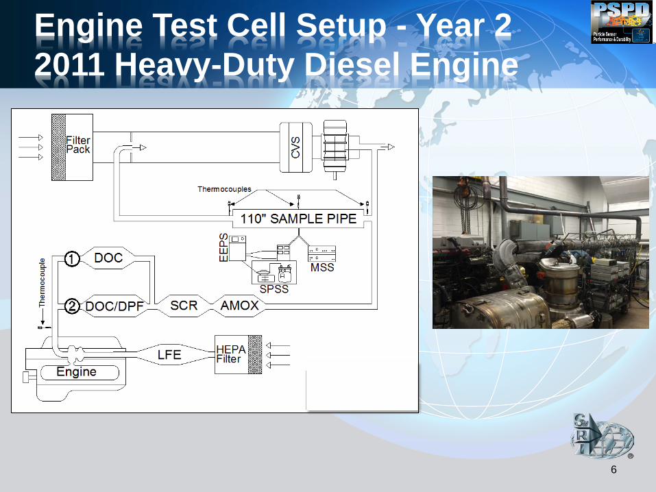
Engine Test Cell Setup - Year 2 2011 Heavy-Duty Diesel Engine
6
7
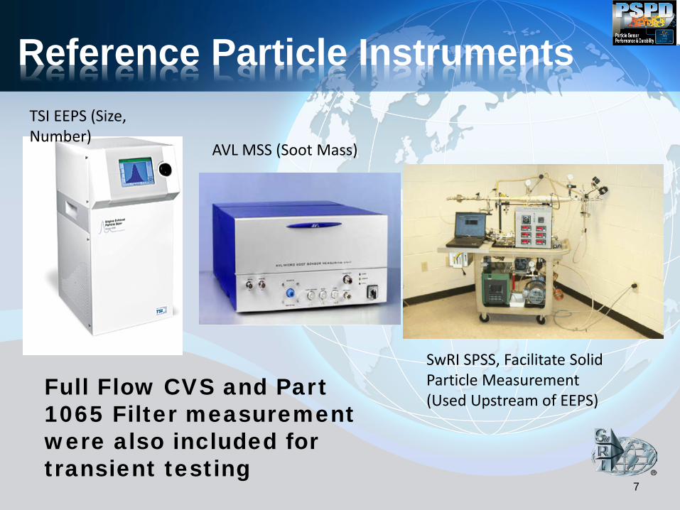
Reference Particle Instruments TSI EEPS (Size, Number)
AVL MSS (Soot Mass)
SwRI SPSS, Facilitate Solid Particle Measurement (Used Upstream of EEPS)
Full Flow CVS and Part 1065 Filter measurement were also included for transient testing

Electricfil Cumulative Sensor
• Particles collect on an electrode with high electric resistor
• Electric resistance decrease with soot loading
• As resistance reaches a threshold, sensor is regenerated, and the process starts again
• Change in resistance over time is determined between:
– End of Regeneration and Beginning of Regeneration
• This sensor provides integrated soot accumulation on the sensor surface over a period of time:
– Time will be short if the concentration is high – Time will be long if the concentration is low – For an engine producing ~0.03 g/hp-hr, four
regeneration events took place in 20 minutes • Even if the sensor is very accurate,
particle deposition will have to be proportional to engine exhaust to get a proper weighting to exhaust emissions, especially under transient operation (a very challenging fluid dynamic problem)
8

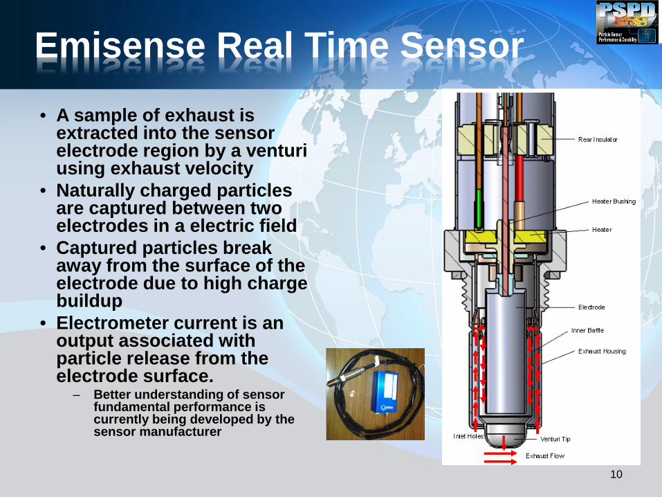
Emisense Real Time Sensor • A sample of exhaust is
extracted into the sensor electrode region by a venturi using exhaust velocity
• Naturally charged particles are captured between two electrodes in a electric field
• Captured particles break away from the surface of the electrode due to high charge buildup
• Electrometer current is an output associated with particle release from the electrode surface.
– Better understanding of sensor fundamental performance is currently being developed by the sensor manufacturer
10

NGK-NTK Real Time Sensor • Air driven by an external pump
is ionized via a positive corona needle to charge the particles
• The high velocity ionized air creates a low pressure region where exhaust enters and mixes with it.
• The excess ions are trapped – Newest design does not include an ion
trap • The positively charged particles
enter and escape a Faraday cup creating a net total charge that is proportional to particle concentration
• No trapping of particles is required for this method to work
11
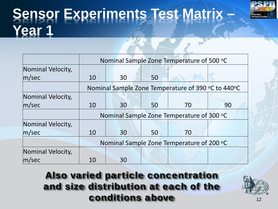
Nominal Sample Zone Temperature of 500 oC Nominal Velocity, m/sec 10 30 50
Nominal Sample Zone Temperature of 390 oC to 440oC Nominal Velocity, m/sec 10 30 50 70 90 Nominal Sample Zone Temperature of 300 oC Nominal Velocity, m/sec 10 30 50 70 Nominal Sample Zone Temperature of 200 oC Nominal Velocity, m/sec 10 30
12
Sensor Experiments Test Matrix – Year 1
Also varied particle concentration and size distribution at each of the
conditions above
13
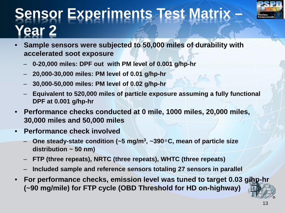
Sensor Experiments Test Matrix – Year 2 • Sample sensors were subjected to 50,000 miles of durability with
accelerated soot exposure – 0-20,000 miles: DPF out with PM level of 0.001 g/hp-hr – 20,000-30,000 miles: PM level of 0.01 g/hp-hr – 30,000-50,000 miles: PM level of 0.02 g/hp-hr – Equivalent to 520,000 miles of particle exposure assuming a fully functional
DPF at 0.001 g/hp-hr • Performance checks conducted at 0 mile, 1000 miles, 20,000 miles,
30,000 miles and 50,000 miles • Performance check involved
– One steady-state condition (~5 mg/m3, ~390°C, mean of particle size distribution ~ 50 nm)
– FTP (three repeats), NRTC (three repeats), WHTC (three repeats) – Included sample and reference sensors totaling 27 sensors in parallel
• For performance checks, emission level was tuned to target 0.03 g/hp-hr (~90 mg/mile) for FTP cycle (OBD Threshold for HD on-highway)

• Sensors were exposed to 8 hours of ammonia concentration of ~500 ppm – Same Engine used but with urea injection – FTIR was used to measure NH3 concentration
• Sensors were exposed to 8 hours of 700C temperature – High gas temperature diesel burner with DPF
was used for this work • Sensors were exposed to sub-atmospheric
pressure (0.75 atm) and positive pressure of (1.25 atm), (1 hour for each) – This work was performed off-line
14
Other Sensor Exposures

Results-Example of Sensor Sensitivity After Multiple Exposures
15

16
Results-Sensor Sensitivity Response at Different Velocities and different temperatures
35 m/sec 50 m/sec
17
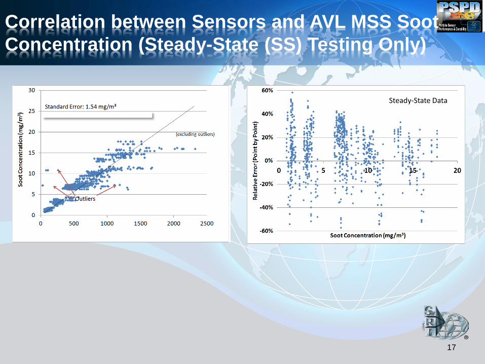
Correlation between Sensors and AVL MSS Soot Concentration (Steady-State (SS) Testing Only)
Steady-State Data
Steady-State Data

18
Sensor Response – Transient & SS
Sensor
Example for Real time Sensor Response Steady State Response
Example for Cumulative-Type Sensor Response • Real time sensors track Micro-
soot sensor reasonably well • Accumulator sensors correlate
rate of change of sensor resistance with soot concentration
• Issue of Sensor Variability observed during SS tests

Summary
• Significant progress has been made in spark-plug sized technology for sensing particle in engine exhaust
• It is critical to continue the development of this process with the help of engine and sensor manufactures and other interested stakeholders
19

Upcoming PSPD II of Consortium Activities (2015 – 2019) • Kickoff Meeting in October 2015 • Particle Natural Charge and Conductivity
Using Different Technology Engines – Several sensor technologies need such information
• Particle Sensor Variability & Accuracy Near Threshold – Sensor to sensor variability – Inherent variability of a sensor
• DPF Soot Leak and Particle Stratification Measurement – Optimal location of sensor in exhaust configuration 20

• This work was funded by PSPD consortium members:
21
Acknowledgments

Southwest Research Institute®
22