particle-based rendering for porous mediahilfer/publikationen/pdfo/zz-2010-sigrad-45.pdfsigrad 2010...
TRANSCRIPT

SIGRAD 2010
Particle-based Rendering for Porous Media
S. Grottel1 and G. Reina1 and T. Zauner2 and R. Hilfer2 and T. Ertl1
1Visualisation Research Center (VISUS), University of Stuttgart, Germany2Institute for Computational Physics, University of Stuttgart, Germany
AbstractParticle-based modeling and simulation of granular or porous media is a widely-used tool in physics and materialscience to study behavior like fracture and failure under external force. Classical models use spherical particles.However, up to 108 polyhedral-shaped particles are required to achieve realistic results comparable to labora-tory experiments. As contact points and exposed surfaces play important roles for the analysis, a meaningfulvisualization aiding the numeric analysis has to represent the exact particle shapes. For particle-based data setswith spherical particles, ray tracing has been established as the state-of-the-art approach yielding high renderingperformance, optimal visual quality and good scalability. However, when rendering polyhedral-shaped particles,there is no issue with visual quality comparing polygon-based rendering approaches and ray casting, whereas thepolygon-based approaches cause significantly lower fragment load. The paper at hand investigates the advantagesand drawbacks of both approaches by analyzing the performance of state-of-the-art rendering methods employingvertex-buffer objects, hardware-supported instancing, geometry shader, and GPU-based ray casting.
Categories and Subject Descriptors (according to ACM CCS): I.3.5 [Computer Graphics]: Computational Geometryand Object Modeling—Curve, surface, solid, and object representations; I.3.8 [Computer Graphics]: Computa-tional Geometry and Object Modeling—Applications.
1. Introduction and Related Work
In many fields of science, including physics and mate-rial science, particle-based simulation is a well-establishedtool for studying material properties and material behav-ior under external forces. Material samples are modeledby large amounts of particles representing discrete entitiesfrom the application domain. In molecular dynamics, theseare usually atoms, or mass-center-based representations ofmolecules, e. g. Lennard-Jones mass centers [GRVE07].These particles have no specific shape, but a simple effec-tive radius, and are thus visualized as spheres. Renderingthese is well understood [Gum03] and high-performancealgorithms are available. Ray casting has been establishedas the state-of-the-art approach for rendering this type ofdata [GRDE10] allowing for interactive visualization of sev-eral millions of spheres on standard desktop computers.For quadratic surfaces, e. g. spheres or cylinders, this ap-proach yields best performance, scalability and visual qual-ity, compared to alternatives like texture-based point spritesor mesh-based approaches. For arbitrarily-shaped, curved
surfaces the superior visual quality of ray casting is also fa-vorable [KHK∗09].
In materials science one is often confronted with ma-terials exhibiting complex stochastic microstructures andtextures. Important examples are porous materials [Hil96].Some classes of porous materials, such as sandstones, ex-hibit a granular microstructure resulting from the physic-ochemical processes that generated the material. Simula-tions of such media often start from models with sphericalgrains, due to the simplicity of handling interactions. How-ever, for realistic results non-spherical particles are required.These can be modeled by composing a grain out of severalspherical sub-grain particles (e. g. employing the discrete el-ement method [JBPE99]). This approach has scalability is-sues when trying to achieve simulation system sizes of 108
grains. This is the required size to be comparable to lab-oratory experiments. Therefore, current simulations try toemploy polyhedral-shaped particles [LBFH10], which, how-ever, complicates the process of evaluating contact points
45

S. Grottel & G. Reina & T. Zauner & R. Hilfer & T. Ertl / Particle-based Rendering for Porous Media
Figure 1: A small porous media sample modeled from10 000 particles of 100 crystallite template types with 18faces each.
and forces. To achieve consistency with numerical analysis,visualizing these particles correctly is of high importance.
The scenario of porous media, e. g. sandstone, which thework at hand specifically looks at, is closely related to vi-sualizing granular media, as such media is also modeledfrom polyhedral-shaped particles, namely quartz crystal-lites [HZWH09]. An exact visualization of the particles isrequired as their shapes define the shape and amount of thesurface of the media in cavities and tunnel networks exposedto surrounding media like gas or liquid (e. g. consider thick-film gas sensors [MC95]).
Rendering arbitrary polyhedral shapes is traditionallyachieved by means of a polygon mesh. Although this isstraightforward, it is not clear whether this is the best ap-proach when visualizing very large data sets. On the onehand, a data set of 1 000 000 particles easily requires up to200 000 000 triangles to be rendered (Tab. 1). On the otherhand, usually there are not a million unique particle meshes,but particles are scaled and rotated instances of only severaldozen particle templates. This fact can be exploited to op-timize the rendering performance, allowing for interactivevisualization of data sets with up to several millions of par-ticles. These data set sizes are currently produced by sim-ulations in the application domain. A similar approach wasused by Lampe et al. [LVRH07] to visualize large proteinsby rendering instances of amino acids instead of individualatoms.
The main contribution of this work is the presentationand comparison of state-of-the-art rendering techniques thatyield polyhedra. The detailed performance analysis identi-fies the best approach based on data set size and particlecomplexity.
Figure 2: Comparison of 2D sections (2.25 mm × 2.25 mm)experimental data (µ-CT; left) with reconstructed model(right) of Fontainebleau sandstone. Grains are shown ingray, while space in-between is shown in black. The recon-structed model is stochastically very similar to the experi-mental data. The degree of stochastic similarity was mea-sured and documented quantitatively using numerous geo-metric observables described in detail in [LBFH10].
2. Modeling Porous Media
Porous media may be loosely characterized as materials con-taining a complex system of internal surfaces and phaseboundaries [Hil96]. The random appearance of the phaseboundaries has lead to a variety of stochastic models [Hil02,Hil00]. Stochastic reconstruction models for porous me-dia have been investigated extensively in [MH99, MTH00,BH99].
A fundamental drawback of stochastic reconstructionmodels as well as segmentation of 3D X-ray or synchrotronmicrotomograms obtained from scattering experiments isthe representation of the microstructure on a regular (cubic)lattice [BHK∗09]. Such a representation at a single, fixedresolution precludes multiscale modeling of porous media,because only a single scale can be represented with currentlyavailable data manipulation capacities. Recently this funda-mental limitation of lattice-based models was overcome instochastic continuum models [BHK∗09,BØH∗09,LBFH10].
Visualization and 3D-imaging of stochastic continuummodels is important for identifying and modeling regionsof interest in multiscale porous media, such a microporousregions with sub-micron-sized pores or microcrystalline re-gions with nanometer crystallites. It has never been carriedout for multiscale sandstones due to the lack of suitable mod-els on the pore scale. Here we report a first step in this di-rection. We present fast visualizations of continuum mod-els for sandstones with polyhedral grains obtained from anovel molecular dynamics method of generating the stochas-tic point process underlying the stochastic continuum mod-els. While the molecular dynamics method will be describedelsewhere, we report here details of the rendering technique.
When visualizing media modeled by such crystallites wecan exploit several factors. The rather small number of crys-tallite template types makes this scenario a perfect candidate
46
S. Grottel & G. Reina & T. Zauner & R. Hilfer & T. Ertl / Particle-based Rendering for Porous Media
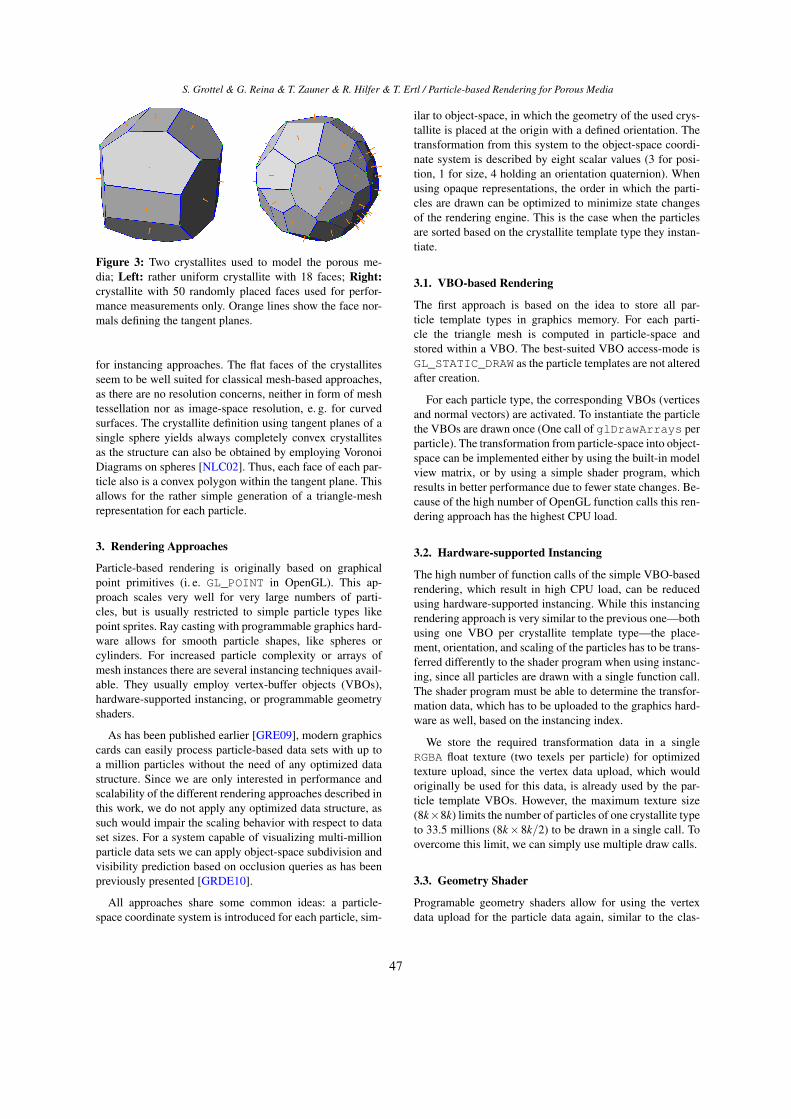
Figure 3: Two crystallites used to model the porous me-dia; Left: rather uniform crystallite with 18 faces; Right:crystallite with 50 randomly placed faces used for perfor-mance measurements only. Orange lines show the face nor-mals defining the tangent planes.
for instancing approaches. The flat faces of the crystallitesseem to be well suited for classical mesh-based approaches,as there are no resolution concerns, neither in form of meshtessellation nor as image-space resolution, e. g. for curvedsurfaces. The crystallite definition using tangent planes of asingle sphere yields always completely convex crystallitesas the structure can also be obtained by employing VoronoiDiagrams on spheres [NLC02]. Thus, each face of each par-ticle also is a convex polygon within the tangent plane. Thisallows for the rather simple generation of a triangle-meshrepresentation for each particle.
3. Rendering Approaches
Particle-based rendering is originally based on graphicalpoint primitives (i. e. GL_POINT in OpenGL). This ap-proach scales very well for very large numbers of parti-cles, but is usually restricted to simple particle types likepoint sprites. Ray casting with programmable graphics hard-ware allows for smooth particle shapes, like spheres orcylinders. For increased particle complexity or arrays ofmesh instances there are several instancing techniques avail-able. They usually employ vertex-buffer objects (VBOs),hardware-supported instancing, or programmable geometryshaders.
As has been published earlier [GRE09], modern graphicscards can easily process particle-based data sets with up toa million particles without the need of any optimized datastructure. Since we are only interested in performance andscalability of the different rendering approaches described inthis work, we do not apply any optimized data structure, assuch would impair the scaling behavior with respect to dataset sizes. For a system capable of visualizing multi-millionparticle data sets we can apply object-space subdivision andvisibility prediction based on occlusion queries as has beenpreviously presented [GRDE10].
All approaches share some common ideas: a particle-space coordinate system is introduced for each particle, sim-
ilar to object-space, in which the geometry of the used crys-tallite is placed at the origin with a defined orientation. Thetransformation from this system to the object-space coordi-nate system is described by eight scalar values (3 for posi-tion, 1 for size, 4 holding an orientation quaternion). Whenusing opaque representations, the order in which the parti-cles are drawn can be optimized to minimize state changesof the rendering engine. This is the case when the particlesare sorted based on the crystallite template type they instan-tiate.
3.1. VBO-based Rendering
The first approach is based on the idea to store all par-ticle template types in graphics memory. For each parti-cle the triangle mesh is computed in particle-space andstored within a VBO. The best-suited VBO access-mode isGL_STATIC_DRAW as the particle templates are not alteredafter creation.
For each particle type, the corresponding VBOs (verticesand normal vectors) are activated. To instantiate the particlethe VBOs are drawn once (One call of glDrawArrays perparticle). The transformation from particle-space into object-space can be implemented either by using the built-in modelview matrix, or by using a simple shader program, whichresults in better performance due to fewer state changes. Be-cause of the high number of OpenGL function calls this ren-dering approach has the highest CPU load.
3.2. Hardware-supported Instancing
The high number of function calls of the simple VBO-basedrendering, which result in high CPU load, can be reducedusing hardware-supported instancing. While this instancingrendering approach is very similar to the previous one—bothusing one VBO per crystallite template type—the place-ment, orientation, and scaling of the particles has to be trans-ferred differently to the shader program when using instanc-ing, since all particles are drawn with a single function call.The shader program must be able to determine the transfor-mation data, which has to be uploaded to the graphics hard-ware as well, based on the instancing index.
We store the required transformation data in a singleRGBA float texture (two texels per particle) for optimizedtexture upload, since the vertex data upload, which wouldoriginally be used for this data, is already used by the par-ticle template VBOs. However, the maximum texture size(8k×8k) limits the number of particles of one crystallite typeto 33.5 millions (8k×8k/2) to be drawn in a single call. Toovercome this limit, we can simply use multiple draw calls.
3.3. Geometry Shader
Programable geometry shaders allow for using the vertexdata upload for the particle data again, similar to the clas-
47

S. Grottel & G. Reina & T. Zauner & R. Hilfer & T. Ertl / Particle-based Rendering for Porous Media
#Faces #Triangles #Vertices(unique/drawn)
4 4 4/1210 ∼ 26 ∼ 15/∼ 4620 ∼ 68 ∼ 36/∼ 10850 ∼ 200 ∼ 98/∼ 300
Table 1: Number of triangles and vertices per crystallite fora given number of faces; the numbers vary slightly for thedifferent crystallite templates due to the different plane cut-ting conditions. The two numbers of vertices show the num-ber of unique vertices, required when storing the mesh datain VBOs, and the number of vertices needed to be drawnbased on the number of triangles (relevant for the geometryshader approach).
sical approach. The idea is to upload point data and per-form the crystallite template instancing through the geome-try shader. We generate one shader for each crystallite type,which is similar to the idea employed by [LVRH07]. Thetriangle-meshes of the crystallites are stored not in VBOsbut in the corresponding geometry shader’s code directly.The calculation of the mesh is done on the CPU. We thengenerate a geometry shader code which outputs this meshdirectly in normalized device coordinates. The output typeGL_TRIANGLE_STRIP allows to efficiently render eachface of a crystallite, similar to the previously described ap-proaches.
Since the output size of each geometry shader is known,load-balancing within the graphics hardware should be pos-sible. However, the maximum number of vertices outputfrom the geometry shader is limited. On current graph-ics cards, the limit† of scalar values output per geometryshader invocation is 1024, resulting in a maximum numberof 1024/8 = 128 vertices (8 components since we need toset gl_Position and gl_FrontColor). Table 1 showsthat crystallites with 20 faces are already very close to thatlimit (23-24 faces exceed the limit). However, this limit isnot crucial, since 18 faces are sufficient to achieve a realisticmodel, as stated in section 2. Nevertheless, if more complexcrystallites are required in future, the geometry shader ap-proach will need to be modified (e. g. splitting up the crys-tallites into several shaders), which will introduce more statechanges and additional data to be uploaded.
3.4. Ray Casting
The original particle-based visualization works with pointprimitives and GPU-based ray casting of implicit surfacesresulting in perspective-correct object appearance of each
† GL_MAX_GEOMETRY_TOTAL_OUTPUT_COMPONENTS, seethe geometry shader extension specification [Geo]
Vie
win
g D
irec
tion
p1
p2
p3
p4
n3
n2n1
r1r2
Figure 4: The principle of ray casting convex polyhedra (in2D convex polygons). Viewing ray r1 hits tangent plane ofnormal n1 at point p1. Hit point p2 is the farthest front facehit point and thus the correct point. Viewing ray r2 wouldchoose p3 this way. However the front-most back face hitpoint p4 with plane of normal n3 is closer to the viewer.Thus viewing ray r2 does not hit the polyhedron (polygon)at all.
particle. This approach is especially beneficial for smoothquadratic surfaces, like spheres, due to the always optimalimage-space resolution. However the ray casting gets moreand more computationally intense the more intersections be-tween the viewing ray and particle geometry have to be cal-culated.
The central idea of GPU-based glyph ray casting fol-lows the approach of point sprites, for which OpenGLGL_POINTS are extended to image-space window-alignedquads. While the classical point-sprite approach places a tex-ture on each quad, e. g. the image of a sphere, GPU-basedray casting performs a single ray casting step, also known aslocal ray tracing, in the fragment shader for each fragment,calculating the perspective correct rendering of any implicitsurface encoded in the ray-surface intersection equation.
For the polyhedral-shaped particles used in this paper, aviewing-ray plane intersection has to be calculated for eachtangent-plane of the crystallite. For each intersection, a sim-ple dot product of the viewing ray and the plane normalspecifies whether the plane was hit front-side. The correctintersection is the farthest hit of a front face. However, if thenearest hit of a back face is in front of this one, the crystalliteis not hit at all (See Fig. 4). Note that no sorting of intersec-tions needs to be performed because simple min and maxoperations during the hit tests are sufficient. This approachis basically similar to the work on bounding objects for raytracing presented by Kay and Kajiya [KK86].
Similar to the idea of the geometry shader-based ap-proach, we can render all particles using a single draw callwith one shader for each crystallite template type performingthe ray casting and lighting operations.
48
S. Grottel & G. Reina & T. Zauner & R. Hilfer & T. Ertl / Particle-based Rendering for Porous Media
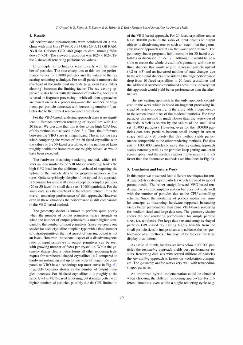
4. Results
All performance measurements were conducted on a ma-chine with Intel Core I7 980X 3.33 GHz CPU, 12 GB RAM,NVIDIA GeForce GTX 480 graphics card, running Win-dows 7 (x64). The viewport resolution was 1024×1024. Ta-ble 2 shows all rendering performance values.
In principle, all techniques scale linearly with the num-ber of particles. The two exceptions to this are the perfor-mance values for 10 000 particles and the values of the raycasting rendering technique. For small particle numbers theoverhead of the individual methods (e. g. even back bufferclearing) becomes the limiting factor. The ray casting ap-proach scales better with the number of particles, because itis based on fragment processing—while all other approachesare based on vertex processing—and the number of frag-ments per particle decreases with increasing number of par-ticles due to the limited screen-space resolution.
For the VBO-based rendering approach there is no signif-icant difference between rendering of crystallites with 4 to20 faces. We presume that this is due to the high CPU loadof this method as discussed in Sec. 3.1. Thus, the differencebetween the VBO sizes is insignificant. This is not the casewhen comparing the values of the 20-faced crystallite withthe values of the 50-faced crystallite. As the number of facesroughly double the frame-rates are roughly halved, as wouldhave been expected.
The hardware instancing rendering method, which fol-lows an idea similar to the VBO-based rendering, trades thehigh CPU load for the additional overhead of requiring theupload of the particle data to the graphics memory as tex-tures. Quite surprisingly, despite of the upload this approachis favorable for almost all cases, except for complex particles(20 or 50 faces) in small data sets (10 000 particles). For thesmall data sets the overhead of the texture upload limits theoverall rendering performance of this approach. However,even in these situations the performance is still comparableto the VBO-based method.
The geometry shader is known to perform quite poorlywhen the number of output primitives varies strongly orwhen the number of output primitives is much higher com-pared to the number of input primitives. Since we create oneshader for each crystallite template type with a fixed numberof output-primitives the first aspect of varying output is notan issue. However, the second aspect of a disadvantageousratio of input primitives to output primitives can be seenwith growing number of faces per crystallite. While the ge-ometry shader clearly outperforms all other rendering tech-niques for tetrahedral-shaped crystallites (×2 compared tohardware instancing and up to one order of magnitude com-pared to VBO-based rendering; top-most curve in Fig. 6),it quickly becomes slower as the number of output trian-gles increases. For 10-faced crystallites it is roughly at thesame level as VBO-based rendering, but it scales better withhigher numbers of particles, possibly due the CPU limitation
of the VBO-based approach. For 20-faced crystallites and atleast 100 000 particles the ratio of input objects to outputobjects is disadvantageous to such an extent that the geom-etry shader approach results in the worst performance. Thegeometry shader programs fail to compile for 50-faced crys-tallites as discussed in Sec. 3.3. Although it would be pos-sible to create the whole crystallite’s geometry with two orthree shaders, this would require increased particle upload(×2 or ×3) and an increased number of state changes dueto the additional shaders. Considering the huge performancedrop from 10-faced crystallites to 20-faced crystallites andthe additional overheads mentioned above, it is unlikely thatthis approach would yield better performance than the alter-natives.
The ray casting approach is the only approach consid-ered in the work which is based on fragment-processing in-stead of vertex-processing. It therefore adds a dependencyto the screen-space sizes of the rendered particles. For largeparticles this method is much slower than the vertex-basedmethods, which is shown by the values of the small dataset (10 000 particles). However, even for the 100 000 par-ticles data sets, particles become small enough in screenspace (still 20× 20 pixels) that this method yields perfor-mance comparable to the other rendering methods. For datasets of 1 000 000 particles or more, the ray casting approachscales extremely well, as the particles keep getting smaller inscreen space, and the method reaches frame rates ×2 to ×5faster than the alternative methods (see blue lines in Fig. 6).
5. Conclusion and Future Work
In this paper we presented four different techniques for ren-dering polyhedral-shaped particles which are used to modelporous media. The rather straightforward VBO-based ren-dering has a simple implementation but does not scale wellwith the number of particles due to the CPU-controllingscheme. Since the modeling of porous media has simi-lar concepts as instancing, hardware-supported instancingyields better performance than pure VBO-based renderingfor medium-sized and large data sets. The geometry shadershows the best rendering performance for simple particlesizes, i. e. tetrahedra. For large data sets and complex shapedparticles GPU-based ray casting highly benefits from thesmall particle sizes in image-space and achieves the best per-formance of all methods. This may not be the case for largedisplay installations.
As a rule of thumb, for data set sizes below 1 000 000 par-ticles the instancing approach yields best performance re-sults. Rendering data sets with several millions of particlesthe ray casting approach is fastest on workstation comput-ers. The geometry shader works very well with tetrahedral-shaped particles.
An optimized hybrid implementation could be obtainedwhen choosing the different rendering approaches for dif-ferent situations, even within a single rendering cycle (e. g.
49

S. Grottel & G. Reina & T. Zauner & R. Hilfer & T. Ertl / Particle-based Rendering for Porous Media
Figure 5: The data sets used for the performance measurements (Tab. 2) with (from left to right) 100 000, 1 000 000, 10 000 000,and 100 000 000 particles. The used crystallite types have always 20 faces. All rendering methods produce exactly the sameimages.
#Particles#Faces Technique 10 000 100 000 1 000 000 10 000 000 100 000 000
VBO 644.5 80.0 7.73 0.778 0.0614 Inst 1259.0 295.6 34.3 3.03 0.254
GPUGeom 1430.1 524.8 69.0 7.51 0.747Raycast 181.3 81.7 25.9 4.31 0.566VBO 635.5 80.1 7.7 0.758 0.064
10 Inst 962.6 209.4 24.8 1.98 0.16GPUGeom 612.8 88.1 9.1 0.911 0.086Raycast 160.0 62.9 19.3 3.19 0.39VBO 610.6 76.6 7.64 0.682 0.066
20 Inst 592.3 105.8 11.5 1.12 0.094GPUGeom 174.1 19.2 1.86 0.183 0.018Raycast 133.8 61.0 15.2 2.11 0.25VBO 315.2 38.0 3.87 0.37 0.038
50 Inst 306.7 40.9 4.1 0.392 0.039GPUGeom – – – – –Raycast 117.1 45.5 8.85 1.09 0.118
Table 2: The rendering performance values in FPS achieved by the different rendering techniques for different data sets.#Faces are the number of crystallite faces (not triangles). Details on the rendering techniques can be found in the correspondingsubsections: VBO in Sec. 3.1, Inst in Sec. 3.2, GPUGeom in Sec. 3.3, and Raycast in Sec. 3.4. Note that the geometry shaderwas unable to compile for crystallites with 50 faces (see Sec. 3.3 for discussion).
using ray casting for many small particles in the background,while using instancing for the big particles in the fore-ground). However, such an implementation would be quitecomplex. Considering the fact that ray casting is always in-teractive and for large data sets it is even the fastest method,it is dubitable if this effort is justified.
There are some further improvements to the presentedmethods and additional methods we would like to investi-gate as future work. The geometry shader approach couldbe further optimized by only generating front faces. Sim-ilar to the test performed by the ray casting approach thegeometry shader could perform a back-face culling whichwould roughly decrease the number of output primitives bya factor of two. However, assuming there were no overhead,the geometry shader would then e. g. reach the performance
values of 10-faced crystallites for 20-faced crystallites, andthus, would still be slower than hardware-supported instanc-ing for crystallites of relevant size. Nevertheless, the geom-etry shader approach could benefit from future hardware ar-chitectures.
Beyond the question of fast rendering the visual evalu-ation of material properties arises. When rendering addi-tional information, e. g. onto the surface of each crystallite,the evaluation conditions on which rendering method to ap-ply may change. Mesh-based approaches have the advantageof easily usable texture-coordinates, while ray casting is al-ready performed on a per-fragment basis e. g. allowing foron-the-fly evaluation of a 3D scalar field, like a distance fieldto the particle surfaces. For future work we plan to analyzethese aspects, not only for rendering but also for GPU-based
50

S. Grottel & G. Reina & T. Zauner & R. Hilfer & T. Ertl / Particle-based Rendering for Porous Media
0,01
0,1
1
10
100
1000
10000FP
S
# Particles
VBO 4 VBO 20 Inst 4 Inst 20GPUGeom 4 GPUGeom 20 Raycast 4 Raycast 20
Figure 6: Rendering performance of all methods in FPS fortetrahedral-shaped crystallites (dashed lines) and 20-facedcrystallites (solid lines). Geometry shader for 4-faced crys-tallite is fastest (orange line). Most methods decrease lin-early with the number of particles, except for when renderingvery few particles. Ray casting results (blue lines) decreasemore slowly than linear and thus are beneficial for large datasets.
evaluation, especially when applied not to the particles them-selves but to the empty space in between.
Acknowledgements
This work is partially funded by Deutsche Forschungsge-meinschaft (DFG) as part of SFB 716 projects B.3 and D.3.
References[BH99] BISWAL B., HILFER R.: Microstructure analysis of re-
constructed porous media. Physica A 266 (1999), 307. 2
[BHK∗09] BISWAL B., HELD R., KHANNA V., WANG J., HIL-FER R.: Towards precise prediction of transport properties fromsynthetic computer tomography of reconstructed porous media.Physical Review E 80 (2009), 041301. 2
[BØH∗09] BISWAL B., ØREN P., HELD R., BAKKE S., HILFERR.: Modeling of multiscale porous media. Image Analysis andStereology 28 (2009), 23–34. 2
[Geo] GLSL geometry shader 4 extension specification.http://developer.download.nvidia.com/opengl/specs/GL_EXT_geometry_shader4.txt. 4
[GRDE10] GROTTEL S., REINA G., DACHSBACHER C., ERTLT.: Coherent Culling and Shading for Large Molecular DynamicsVisualization. Computer Graphics Forum 29, 3 (2010), 953–962.http://www.visus.uni-stuttgart.de/megamol. 1, 3
[GRE09] GROTTEL S., REINA G., ERTL T.: Optimized DataTransfer for Time-dependent, GPU-based Glyphs. In Proceed-ings of IEEE Pacific Visualization Symposium 2009 (2009),pp. 65–72. 3
[GRVE07] GROTTEL S., REINA G., VRABEC J., ERTL T.: Vi-sual Verification and Analysis of Cluster Detection for MolecularDynamics. vol. 13, pp. 1624–1631. 1
[Gum03] GUMHOLD S.: Splatting Illuminated Ellipsoids withDepth Correction. In Workshop on Vision, Modelling, and Vi-sualization VMV’03 (2003), pp. 245–252. 1
[Hil96] HILFER R.: Transport and relaxation phenomena inporous media. Adv. Chem. Phys. XCII (1996), 299. 1, 2
[Hil00] HILFER R.: Local porosity theory and stochastic recon-struction for porous media. In Räumliche Statistik und Statistis-che Physik (2000), Stoyan D., Mecke K., (Eds.), Lecture Notesin Physics, Vol. 254, Springer, p. 203. 2
[Hil02] HILFER R.: Review on scale dependent characterizationof the microstructure of porous media. Transport in Porous Me-dia 46 (2002), 373. 2
[HZWH09] HARTING J., ZAUNER T., WEEBER R., HILFER R.:Numerical Modeling of Fluid Flow in Porous Media and inDriven Colloidal Suspensions. Springer, 2009, p. 349. 2
[JBPE99] JENSEN R. P., BOSSCHER P. J., PLESHA M. E., EDILT. B.: DEM simulation of granular media-structure interface:effects of surface roughness and particle shape. InternationalJournal for Numerical and Analytical Methods in Geomechanics23, 6 (1999), 531–547. 1
[KHK∗09] KNOLL A., HIJAZI Y., KENSLER A., SCHOTT M.,HANSEN C., HAGEN H.: Fast Ray Tracing of Arbitrary ImplicitSurfaces with Interval and Affine Arithmetic. Computer Graph-ics Forum 28, 1 (2009), 26–40. 1
[KK86] KAY T. L., KAJIYA J. T.: Ray tracing complex scenes. InSIGGRAPH ’86: Proceedings of the 13th annual conference onComputer graphics and interactive techniques (New York, NY,USA, 1986), ACM, pp. 269–278. 4
[LBFH10] LATIEF F., BISWAL B., FAUZI U., HILFER R.:Continuum reconstruction of the pore scale microstructure forfontainebleau sandstone. Physica A: Statistical Mechanics andits Applications 389, 8 (2010), 1607 – 1618. 1, 2
[LVRH07] LAMPE O. D., VIOLA I., REUTER N., HAUSER H.:Two-Level Approach to Efficient Visualization of Protein Dy-namics. IEEE Transactions on Visualization and ComputerGraphics 13, 6 (2007), 1616–1623. 2, 4
[MC95] MARTINELLI G., CAROTTA M. C.: Thick-film gas sen-sors. Sensors and Actuators B: Chemical 23, 2-3 (1995), 157 –161. 2
[MH99] MANWART C., HILFER R.: Reconstruction of randommedia using Monte Carlo methods. Physical Review E 59 (1999),5596. 2
[MTH00] MANWART C., TORQUATO S., HILFER R.: Stochasticreconstruction of sandstones. Phys.Rev.E 62 (2000), 893. 2
[NLC02] NA H.-S., LEE C.-N., CHEONG O.: Voronoi diagramson the sphere. Computational Geometry 23, 2 (2002), 183 – 194.3
51