partial computing offloading assisted cloud point
TRANSCRIPT

1
Partial Computing Offloading Assisted Cloud PointRegistration in Multi-robot SLAM
Biwei Li, Zhenqiang Mi, Member, IEEE, Yu Guo, Student Member, IEEE, Yang Yang andMohammad S. Obaidat, Fellow, IEEE
Abstract—Multi-robot visual simultaneous localization andmapping (SLAM) system is normally consisted of multiple mobilerobots equipped with camera and/or other visual sensors. Thenetworked robots work independently or cooperatively in anunknown scene in order to solve autonomous localization andmapping problem. One of the most critical issues in Multi-robot visual SLAM is the intensive computation that is normallyrequired yet overwhelming for inexpensive mobile robots withlimited on-board resources. To address this problem, a noveltask offloading strategy and dense point cloud map constructionmethod is proposed in this paper. First, we develop a novelstrategy to remotely offload computation-intensive tasks to cloudcenter, so that the tasks that could not originally be achievedlocally on the resource-limited robot systems become possible.Second, a modified iterative closest point algorithm (ICP), namedfitness score hierarchical ICP algorithm (FS-HICP), is developedto accelerate point cloud registration. The correctness, efficiency,and scalability of the proposed strategy are evaluated with boththeoretical analysis and experimental simulations. The resultsshow that the proposed method can effectively reduce the energyconsumption while increase the computation capability and speedof the multi-robot visual SLAM system, especially in indoorenvironment.
Index Terms—Multi-robot system, computing offloading,SLAM system, ICP algorithm.
I. INTRODUCTION
THE aim of simultaneous localization and mapping(SLAM) technology is to provide good estimate of both
the robot pose and the map in unknown environments, wherean accurate map is unavailable [1]. With the rapid develop-ment of onboard hardware, software and machine learningtechnology, increasing research interests have been witnessedon using SLAM technology to solve various complicatedtasks in daily life, e.g., fire rescue, geological exploration,underwater search and archaeological excavation. In orderto adapt to practical applications, one of the most notableresearch interests is three-dimensional SLAM. At present laser
Manuscript received... This work has been supported by the NationalNatural Science Foundation of China under Grant No. 61772068, Grant61472033 and Grant 61672178, Fundamental Research Funds for the CentralUniversities under Grant No. FRF-GF-17-B28, and Ministry of Education ofthe People’s Republic of China Oversea Distinguished Professorship Grantgiven to Prof. Obaidat under Grant No. MS2017BJKJ003. (Correspondingauthor: Zhenqiang Mi.)
B. Li, Z. Mi, Y. Guo, and Y. Yang are with the School of Com-puter and Communication Engineering, University of Science and Tech-nology Beijing, Beijing 100083, China (e-mail: [email protected];[email protected]; [email protected]; [email protected];)
M. S. Obaidat is with ECE Department, Nazarbayev University, Kaza-khstan, King Abdullah II School of Information Technology, the University ofJordan, and PR China Oversees Distinguished Professor, University of Scienceand Technology Beijing, China. (e-mail: [email protected])
radar assisted camera is always used as signal inputs in 3D-SLAM solutions and commercially available products, such asdrones. However, due to the high cost, fast power consumptionand low precision of laser radar, the further application of thelaser radar based 3D-SLAM technique is hindered to be widelyused in the future.
3D visual SLAM, which uses depth cameras as the onlysensor inputs, is considered to be beneficial in scenarios wherethe requirement of cost, energy, and weight of the system isstrict. Due to various advanced cameras, 3D visual SLAM hasattracted more and more attention and opened up a whole newrange of possibilities in robot autonomous navigation field,e.g., virtual reality(VR), augmented reality(AR), and of cause,autonomous driving technology. However, 3D visual SLAMstill faces the challenges of extensive amount of computationand communication tasks where powerful CPU and other on-board resources are required. It turns out that the cost of asingle robot is too high to be applied to the actual scenario.Thus, a new performing model or strategy is of great necessityin the 3D visual SLAM process.
To overcome the aforementioned problem, more researcheshave been conducted to incorporate mobile multi-robot systeminto SLAM, so that the complexity of a task can be shared by agroup of small, often less expensive mobile robots. Generallyspeaking, mobile robots are limited in size and power, whichhinders them from carrying powerful computation and storageunit. Consequently, it might not be fair to ask them to performextensive computation locally. In order to get rid of thisbondage, the cloud robotics proposed by Dr. Kuffner [2] in2010 provides us with a new way to handle complex robottasks. In cooperation with the cloud platform and data center,robotic network can improve its ability by a large margin. Asfor applying cloud robotics to solve multi-robot visual SLAMproblems, there are still some challenges to be tackled.
We summarize the main problems faced by the multi-robot3D visual SLAM into the following three aspects.
1) The main task of 3D visual SLAM system is image pro-cessing, which requires intensive calculations. However,for most inexpensive robotic embedded devices (e.g.,Raspberry Pi), it can hardly be handled in real time.Moreover, some high robustness visual SLAM systems,such as ORB-SLAM [3] and RTAP-MAP [4], can onlybe calculated by powerful computer or even a server.Therefore, how to apply these visual SLAM systems torobotic network needs to be investigated.
2) In order to solve the problem of excessive calculations,some researchers have proposed using cloud robotics to
arX
iv:1
905.
1297
3v1
[cs
.RO
] 3
0 M
ay 2
019

2
offload tasks to cloud. However, images are the only datafor visual SLAM system. The memory space occupiedby image is very large, which may cause certain prob-lems while transmitting, such as communication lossand unexpected latency. For example, Wi-Fi connectionsare not invariably usable and reliable [5]. Moreover,security issues such as hacker interception tend to occurwhen using images as the only input. Hence, a safe andefficient offloading strategy is required.
3) The state of art SLAM systems which can be used inrobot embedded devices always have latency and cannotmake sure the robustness of the system. After a longrunning, robots always lost themselves and cannot berestarted in a short time. In the condition of absence ofany priori artificial calibration, how to achieve real-timecalculation as well as ensure system robustness also needto be studied.
According to the above analyses, it is found that the mainproblems need to be solved are the insufficient on-board com-puting power and limited network transmission bandwidth,which cause multi-robot visual SLAM system very hard toachieve high robustness and real-time calculation. Therefore,we will tackle the aforementioned challenges with a two-step strategy. In the first step, we elaborate on the partialcomputing offloading method. Second, we proposed a noveliterative closest point algorithm to reduce the computationalcomplexity of multi-robot visual SLAM system.
The main contributions of our work can be summarized asfollows.
1) A novel partial offloading strategy: It is built to balancethe calculation of local robots and cloud. To take fulladvantage of local computing and cloud computing,a strategy to offload most of the computation intothe powerful cloud while reducing the amount of datawhich needs to be transmitted is designed. An efficientalgorithm is proposed to find the best offloading pointof the system. By this way, incomplete information isoffloaded to the cloud in which case even if a hackerintercepts the network, it is hard for them to stealreal and complete image information. In addition, thismethod greatly reduces the energy consumption as wellas decreases the processing time.
2) Improvement of point cloud map registration algorithm:One of the two main tasks of SLAM is map building,which is especially important for multi-robot SLAM sys-tem. The robots work independently in the environmentand the maps built by each of them need to be matched.In order to reduce the complexity of the whole SLAMsystem, we improved classic registration algorithm, it-erative closest point (ICP) algorithm, by proposing anovel fitness score hierarchical iterative closest point(FS-HICP) algorithm. The improved algorithm reducesthe time costs and energy consuming.
3) Construction of dense and semi-dense point cloud map:We build global dense point cloud map because it ismore universal and observable. Additionally, due to thefact that multi-robot may be used for obstacle avoidance,
path planning and other applications. In order to describewhether the scene is accessible, a semi-dense octree mapis also constructed.
We also conduct extensive simulation and experimentalevaluations to demonstrate the efficiency of the methods. Ourpartial offloading strategy and the FS-HICP algorithm cangreatly reduce the whole system running time and save theenergy consuming.
The rest of this paper is organized as follows. SectionII presents a brief survey of the related works. Section IIIpresents the system model, and then introduces the formulationof the partial offloading problem and multi-robot registrationmodel. Details of our method are shown in Section IV. SectionV gives the evaluation results. Finally, Section VI concludesthe paper and presents our proposed future work.
II. RELATED WORK
Visual SLAM, as an effective and economical way to helprobot localization and mapping in an unknown environment,has reached substantial robustness and accuracy in the cen-timeter range for single robot applications [6], [7]. ORB-SLAM2 [6] system proposed by Raul Mur-Artal et al., whichuses three threads to work simultaneously, greatly improvesthe efficiency of the algorithm. As multi-robot systems havebeen becoming popular in numerous scenarios, ranging fromsearch and rescue applications to digitization of archeologicalsites. Some researchers [8]–[11] aim to improve the multi-robot SLAM network, for example [10] uses an informationfusion technology, in which the information processed by thesingle robot is collected and optimized by the base station.Another example [11] is based on the multi-robot altitudemap positioning of the unknown initial relative pose. Otherresearchers focus on improving the speed and efficiency ofthe whole system, for instance, MTM (map transformationmatrix) is a multi-robot fast SLAM proposed by HeonCheolLee [12], which only calibrates the particle of the nearestpoint. Of course, there are a lot of successful multi-robot robotmodels [13]–[16], such as five-legged robot [16], using SLAMtechnology to achieve different kinds of tasks in unknownenvironment.
Because the applications environment of multi-robot SLAMare relatively complex, in order to solve the calculationproblem, some successful framework based on cloud robotarchitecture have been proposed, such as DaVinci [17], whichis a software framework that provides the scalability andparallelism advantages of cloud computing implemented inthe FastSLAM algorithm. Rapyuta [18], an open sourcePlatform-as-a-Service (PaaS) framework designed specificallyfor robotics applications such as SLAM, can help robots tooffload heavy computation by providing secured customizablecomputing environments in the cloud. All these frameworkshave verified the feasibility and effectiveness of using “cloud+ robot” synergy in solving SLAM problems.
The performance of robots depends not only on their motionmechanism, but also on their familiarity with the environment.At present, the two-dimensional map creation technology hasbeen well developed, and the three-dimensional map creation
3
technology still has great potential in the enhancement ofefficiency and reduction of cost. A tailoring and scalingiterative closest point (TsICP) algorithm was proposed byLiang Ma [19], which considers the problem of merging gridmaps with different resolutions. Authors in [20] introducea global optimal solution to Euclidean registration in 3D.The work in [21] modifies the well-known iterative closestpoint (ICP) algorithm by introducing the concept of deletionmask. Except using traditional method, Rebro University’sMagnusson team proposed a 3D NDT point cloud registrationmethod [22], which has little correlation with the initial value.Since then, many algorithms have been improved based onNDT algorithm. In terms of application, Kinect Fusion [23]proposed by Imperial College and Microsoft Research Institutein 2011, using the point-plane method to realize point cloudmap registration, which opened a prelude of real-time 3Dreconstruction with RGB-D camera.
To date, most successful local SLAM systems have theproblem of too much calculation. Thus, the “cloud robotic”technology is proposed to solve this problem. However, theymainly focus on the multi-robot network structure, networktransmission path, data compression and so on, without consid-ering combining cloud computing and local computing, suchas [24], [25], [28], [29]. Different from most works mentionedabove, in this paper, a novel strategy is used to choose aoffloading point, reducing energy consuming by offloadingpart of the calculation to cloud. In addition, this paper proposesan improved ICP algorithm realizing multi point cloud mapregistration, with the objective to reduce the times of iterationsas well as improve convergence accuracy.
III. SYSTEM MODEL AND PROBLEMFORMULATION
In this section, firstly the total system framework is pre-sented. Then the model of multi-robot partial computingoffloading is proposed. Finally, the multi-robot dense pointcloud map model and its calculation method is introduced.
A. System Framework
In this paper, it is assumed that multi-robot system worksindependently to execute tasks of SLAM in an unknownindoor scenario. In the SLAM system, the two main tasksare localization and mapping. Localization which includestracking thread, localmapping thread and loopclosing thread ismainly meant to calculate the trajectory and keyframe of therobot in an unknown environment. Mapping is mainly usedto construct a global map of the scene based on local mapsgot by each robot. In the system model, the keyframes andtrajectory got by localization of each robots are used by themapping process.
During the localization process, robots may lost themselvesunexpectedly, especially when running for an extended periodof time because the indoor environment is usually complicated.If the complexity of the algorithm for better robustness andaccuracy is increased, it will lead to too much computation.On this condition if all the data (captured images) is offloadedto cloud to compute, the transmission will be too slow due
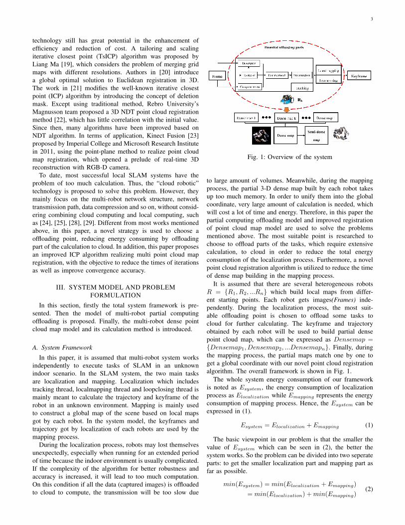
Fig. 1: Overview of the system
to large amount of volumes. Meanwhile, during the mappingprocess, the partial 3-D dense map built by each robot takesup too much memory. In order to unify them into the globalcoordinate, very large amount of calculation is needed, whichwill cost a lot of time and energy. Therefore, in this paper thepartial computing offloading model and improved registrationof point cloud map model are used to solve the problemsmentioned above. The most suitable point is researched tochoose to offload parts of the tasks, which require extensivecalculation, to cloud in order to reduce the total energyconsumption of the localization process. Furthermore, a novelpoint cloud registration algorithm is utilized to reduce the timeof dense map building in the mapping process.
It is assumed that there are several heterogeneous robotsR = {R1, R2, ...Rn} which build local maps from differ-ent starting points. Each robot gets images(Frames) inde-pendently. During the localization process, the most suit-able offloading point is chosen to offload some tasks tocloud for further calculating. The keyframe and trajectoryobtained by each robot will be used to build partial densepoint cloud map, which can be expressed as Densemap ={Densemap1, Densemap2, ...Densemapn}. Finally, duringthe mapping process, the partial maps match one by one toget a global coordinate with our novel point cloud registrationalgorithm. The overall framework is shown in Fig. 1.
The whole system energy consumption of our frameworkis noted as Esystem, the energy consumption of localizationprocess as Elocalization while Emapping represents the energyconsumption of mapping process. Hence, the Esystem can beexpressed in (1).
Esystem = Elocalization + Emapping (1)
The basic viewpoint in our problem is that the smaller thevalue of Esystem which can be seen in (2), the better thesystem works. So the problem can be divided into two seperateparts: to get the smaller localization part and mapping part asfar as possible.
min(Esystem) = min(Elocalization + Emapping)
= min(Elocalization) +min(Emapping)(2)
4
The next two parts will introduce the models to get theminimum value of Elocalization and Emapping , respectively.
B. Partial Computing Offloading Model
In a nutshell, partial computing offloading can be summa-rized as encapsulating partial high-density computing tasksthat would otherwise be performed by local robot nodes intoa central processor or cloud to execute, by which way theenergy consumption of robot can be reduced and the networkefficiency will be improved. It is shown in Fig. 2.
Fig. 2: Partial offloading model
In the multi-robot system, suppose the energy consumptionof robot Rk is Elk, Elocalization can be summarized as (3).
Elocalization =
n∑k=0
Elk (3)
For each robot in the system has the same status level; wecan calculate the minimum value of each Elk in order to getthe minimum value of the Elocalization,. In the partial offload-ing model proposed, some parts of the tasks are calculated bylocal devices while the others are calculated by cloud. It issupposed that Elocal represents the energy consumed by one ofthe local embedded device while Ecloud represents the energyconsumed by cloud. Transmission consuming is expressed byEtr. The calculation of Elk is given in (4).
Elk = Elocal + Ecloud + Etr (4)
Problem description: With Elk as the energy consumptionof each robots, our aim is to choose a suitable offloading point,which can make each Elk reach its minimum value, at whichtime the Elocalization can reach its minimum value.
C. Registration Of Point Cloud Map Model
If every frame of the point cloud is merged into the map,the capacity of the local map will be too large, which willreduce the real-time performance of the system. As the poseof adjacent frames change very little, it is proposed to use keyframes to build the point could map.
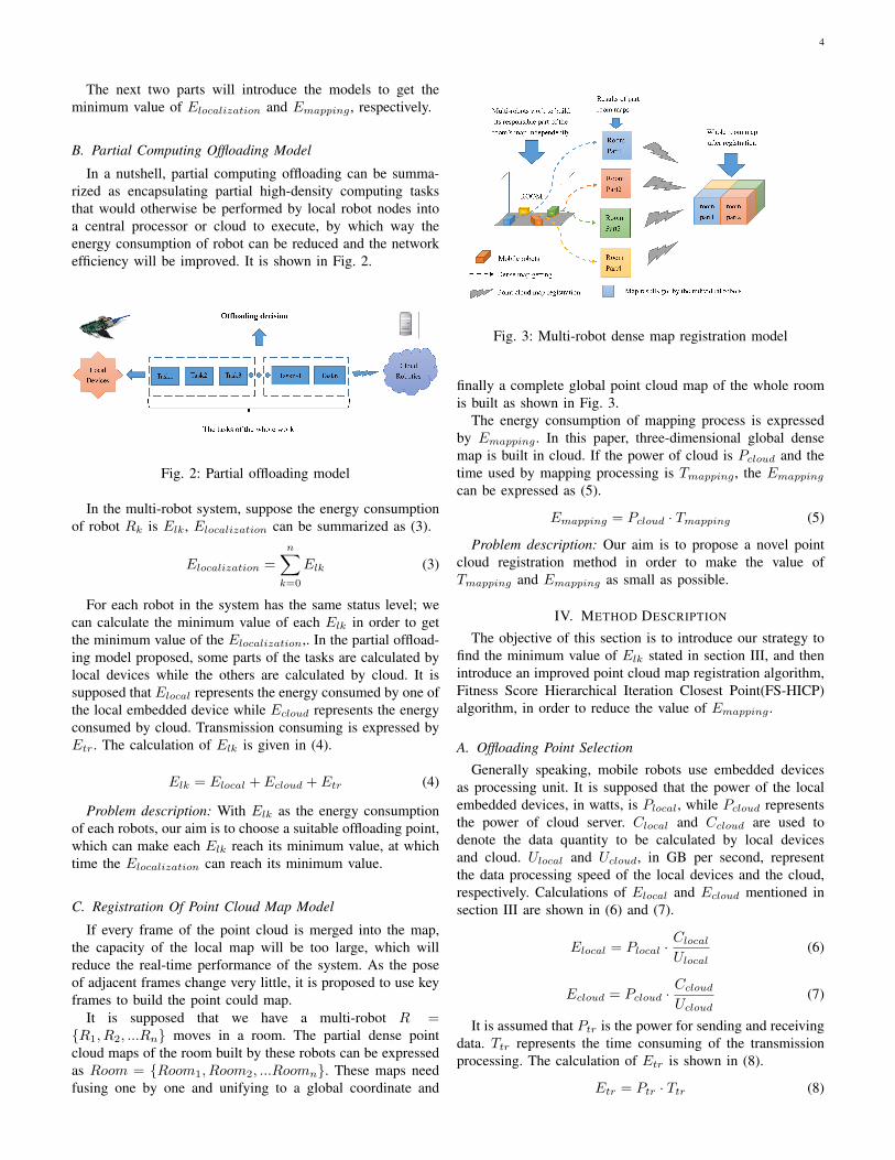
It is supposed that we have a multi-robot R ={R1, R2, ...Rn} moves in a room. The partial dense pointcloud maps of the room built by these robots can be expressedas Room = {Room1, Room2, ...Roomn}. These maps needfusing one by one and unifying to a global coordinate and
Fig. 3: Multi-robot dense map registration model
finally a complete global point cloud map of the whole roomis built as shown in Fig. 3.
The energy consumption of mapping process is expressedby Emapping . In this paper, three-dimensional global densemap is built in cloud. If the power of cloud is Pcloud and thetime used by mapping processing is Tmapping , the Emapping
can be expressed as (5).
Emapping = Pcloud · Tmapping (5)
Problem description: Our aim is to propose a novel pointcloud registration method in order to make the value ofTmapping and Emapping as small as possible.
IV. METHOD DESCRIPTION
The objective of this section is to introduce our strategy tofind the minimum value of Elk stated in section III, and thenintroduce an improved point cloud map registration algorithm,Fitness Score Hierarchical Iteration Closest Point(FS-HICP)algorithm, in order to reduce the value of Emapping .
A. Offloading Point Selection
Generally speaking, mobile robots use embedded devicesas processing unit. It is supposed that the power of the localembedded devices, in watts, is Plocal, while Pcloud representsthe power of cloud server. Clocal and Ccloud are used todenote the data quantity to be calculated by local devicesand cloud. Ulocal and Ucloud, in GB per second, representthe data processing speed of the local devices and the cloud,respectively. Calculations of Elocal and Ecloud mentioned insection III are shown in (6) and (7).
Elocal = Plocal ·Clocal
Ulocal(6)
Ecloud = Pcloud ·Ccloud
Ucloud(7)
It is assumed that Ptr is the power for sending and receivingdata. Ttr represents the time consuming of the transmissionprocessing. The calculation of Etr is shown in (8).
Etr = Ptr · Ttr (8)

5
So the Elk can be summarized as in (9).
Elk = Elocal + Ecloud + Etr =
Plocal ·Clocal
Ulocal+ Pcloud ·
Ccloud
Ucloud+ Ptr · Ttr
(9)
Suppose η is the offloading point. The time consumed bytasks which have been executed divided by the time consumedby total tasks as the value of η, which can be seen in (10).The value of η is between 0 and 1. When η = 0, all the tasksare computed by cloud and when η = 1, all the tasks arecomputed by local embedded devices. So, Clocal and Ccloud
can be rewritten as is shown in equation (11).
η =
∑ki=0 Ttaski∑nj=0 Ttaskj
(0 ≤ k ≤ n) (10)
{Clocal = Ctotal · η
Ccloud = Ctotal · (1− η)(11)
Because the transmission time is related to the amount ofdata that needs to be transferred at the offloading point, Ttr isa function of η as shown in (12).
Ttr = f(η) (12)
Thus, we substitute (11) and (12) into (9) to get (13).
Elk = Plocal ·Ctotal · ηUlocal
+
Pcloud ·Ctotal · (1− η)
Ucloud+ Ptr · Ttr(η)
(13)
From (13) we known, the value of η determines the valueof Elk. In our experiment parts, we will choose a suitableoffloading point η in order to make Elk get its minimum value.When we know the best offloading point, the steps of partialcomputing offloading model can be seen as follow:
1) Get frames from Kinect camera.2) Based on the value of η, some tasks are calculated on
local embedded devices.3) Store the results calculated by local embedded devices
in a YAML file.4) Send the message(YAML file) to cloud by ROS system.5) Calculate the other part of the SLAM on cloud using
the data uploaded by local devices.The specific implementation process is shown in Fig. 4.The main notations in the offloading model are listed in
Table I.
TABLE I: Important notations
Notation DescriptionPlocal Power of local devicesPcloud Power of cloudPtr Power of network transmissionUlocal Data processing speed of local devicesUcloud Data processing speed of cloud roboticsClocal Calculation of local devicesCcloud Calculation of cloudCtotal Total calculation amountTtr Transmission timeη Offloading point(Independent variable)
Fig. 4: Partial offloading process
B. FS-HICP Algorithm
Suppose Roomp and Roomq are the two point cloud datasets needed to be matched and we simply mark them as Pand Q. First, we search each point pi in the point set P forits nearest point qi in the point set Q as the correspondingpoint. Then the corresponding set of P = {p1, p2, ...pn} is setto Q = {q1, q2, ...qn} to solve a European transformation R,t in order to satisfy (14).
∀i, pi = Rqi + t (14)
The centroid position p and q of the two sets of pointsis calculated and so are the coordinates of each point afterremoving the centroid, shown in (15).
pi′ = pi − p, qi′ = qi − q (15)
Then the rotation matrix based on the following optimiza-tion formula is calculated (16).
R∗ = argmin1
2
n∑i=1
||pi′ −Rqi′||2 (16)
Finally, the t is derived according to R, as shown in (17).
t∗ = p−Rq (17)
The transformation matrix is a fourth-order matrix containstranslation(t) and rotation(R), which can be expressed as (18).
T =
[R t0 1
](18)
The classical ICP algorithm(point-point algorithm) pro-posed by Besl and McKay [26] can be described as P isunchangeable while Q rotates and translates iteratively to getas close as possible to the P . In the improvements of theclassic algorithm, the most famous one is the point-planemethod used by Kinect Fusion [23]. However, both of themcannot achieve registration, quickly and the iteration times andthe overall time costs are too much.
In this paper, the hierarchical iterative closest point algo-rithm based on fitness score (FS-HICP algorithm) is proposed.There are three main improvement in this novel algorithm.
1) The stop condition according to the change of fitnessscore is carefully revised.

6
2) The idea of layered filtering is used to accelerate itera-tion.
3) In the iterative process, the maximum response distancewill be adjusted according to the matching quality, sothat the algorithm can converge in a relatively short time.
The flow of the FS-HICP algorithm is shown in Fig.5.
Fig. 5: The flow of the FS-HICP algorithm
The specific execution steps of the algorithm are as follows:1) Delete the error point and useless point. In this paper, a
point with a depth value of 0 or a depth value greaterthan 7000 is considered to be an invalid point and it willbe rejected. Then the points are filtered and the voxelfilter size is 0.1.
2) Match two point cloud map. In the process the algorithmis iterated twice internally.
3) Determine whether the fitness score is less than a giventhreshold (50%). If not, the source is updated and returnto the second step and continue iteration.
4) Filter with a voxel filter size of 0.05.5) Match two point cloud map. In the process the algorithm
is iterated twice internally.6) Determine whether the fitness score reduces. If not,
the source is updated with a certain probability (30%)and return to the fifth step to continue searching theiteration direction. If the fitness score doesn’t reducemore than three times or the algorithm reaches theconvergence precision, the iteration is stopped. If thefitness score decreases, reduce the minimum iterationdistance between two points, update the source andreturn the fifth step to continue the iteration.
The pseudo code of FS-HICP algorithm is shown in TableII.
V. EXPERIMENTAL RESULTSThis section presents the evaluation results of the improved
methods through extensive simulation and experimental stud-
TABLE II: Pseudo code of the FS-HICP algorithm
Input: Multiple point cloud maps:DataOutput: Transformation matrix:FinalTrans
Global point cloud map1. if (data == ø)2. return ERROR3. end if4. for(i = 1; i ≤ data.size; + + i)5. Source = data[i− 1]6. Target = data[i]7. Setvoxelgrid = 0.18. Setmaxcorrespondancedistance = 0.29. Score = fitnessscore10. while fitnessscore ≥ 0.5 ∗ score11. Align(source)12. Source = source ∗ trans13. FinalTrans = FinalTrans ∗ trans14. Setvoxelgrid = 0.0515. Setmaxcorrespondancedistance = 0.116. do17. Align(source)18. if fitnessscore decrease19. Setmaxcorrespondancedistance =
maxcorrespondancedistance− 0.00120. Source = source ∗ trans21. FinalTrans = FinalTrans ∗ trans22. else23. Update source with a 30% probability24. end if25. until fitnessscore has not been reduced for 3 consecutive times.26. return FinalTrans
TABLE III: Parameter values
Parameters Description ValuePlocal Power of local devices 0.9WPcloud Power of cloud 0.3WPtr Power of network transmission 1.3WUlocal Data processing speed of local devices 1.2G/sUcloud Data processing speed of cloud 3.3G/sCtotal Total calculation amount 1G
ies. The results are two-fold: computing offloading and pointcloud map fusion.
The embedded device used on the multi-robot system in thispaper is Raspberry Pi and data is transferred by Wi-Fi network.The RGB-D image acquisition device is Kinect and the masternode used in the simulation experiment is a desktop computerwith 16G memory and 4-core 3.3 GHz CPU. The ROS systemis used for network transmission. In the simulation experi-ments, the data sets used are RGB-D data sets from TUM(https://vision.in.tum.de/data/datasets/rgbd-dataset/download).
A. Computing Offloading
In this section, it is assumed that the total calculation is1G. The values of the parameters in the partial computingoffloading model are shown in Table III [27]. So the formula(13) can be written as in (19).
Elk =0.9W
1.2G/s·1G ·η+ 0.3W
3.3G/s·1G · (1−η)+1.3W ·Ttr(η)
(19)(19) can be simplified to (20).
Elk = 0.659 · η + 1.3Ttr(η) + 0.091 (20)
7
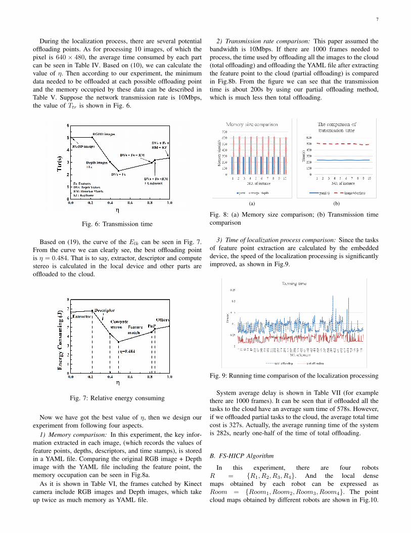
During the localization process, there are several potentialoffloading points. As for processing 10 images, of which thepixel is 640 × 480, the average time consumed by each partcan be seen in Table IV. Based on (10), we can calculate thevalue of η. Then according to our experiment, the minimumdata needed to be offloaded at each possible offloading pointand the memory occupied by these data can be described inTable V. Suppose the network transmission rate is 10Mbps,the value of Ttr is shown in Fig. 6.
Fig. 6: Transmission time
Based on (19), the curve of the Elk can be seen in Fig. 7.From the curve we can clearly see, the best offloading pointis η = 0.484. That is to say, extractor, descriptor and computestereo is calculated in the local device and other parts areoffloaded to the cloud.
Fig. 7: Relative energy consuming
Now we have got the best value of η, then we design ourexperiment from following four aspects.
1) Memory comparison: In this experiment, the key infor-mation extracted in each image, (which records the values offeature points, depths, descriptors, and time stamps), is storedin a YAML file. Comparing the original RGB image + Depthimage with the YAML file including the feature point, thememory occupation can be seen in Fig.8a.
As it is shown in Table VI, the frames catched by Kinectcamera include RGB images and Depth images, which takeup twice as much memory as YAML file.
2) Transmission rate comparison: This paper assumed thebandwidth is 10Mbps. If there are 1000 frames needed toprocess, the time used by offloading all the images to the cloud(total offloading) and offloading the YAML file after extractingthe feature point to the cloud (partial offloading) is comparedin Fig.8b. From the figure we can see that the transmissiontime is about 200s by using our partial offloading method,which is much less then total offloading.
(a) (b)
Fig. 8: (a) Memory size comparison; (b) Transmission timecomparison
3) Time of localization process comparison: Since the tasksof feature point extraction are calculated by the embeddeddevice, the speed of the localization processing is significantlyimproved, as shown in Fig.9.
Fig. 9: Running time comparison of the localization processing
System average delay is shown in Table VII (for examplethere are 1000 frames). It can be seen that if offloaded all thetasks to the cloud have an average sum time of 578s. However,if we offloaded partial tasks to the cloud, the average total timecost is 327s. Actually, the average running time of the systemis 282s, nearly one-half of the time of total offloading.
B. FS-HICP Algorithm
In this experiment, there are four robotsR = {R1, R2, R3, R4}. And the local densemaps obtained by each robot can be expressed asRoom = {Room1, Room2, Room3, Room4}. The pointcloud maps obtained by different robots are shown in Fig.10.
8
TABLE IV: Time using of each part in the localization processing
Items Extractor Descriptor Compute stereo Feature match PnP Others Totaltime(s) 0.0154 0.0124 0.0062 0.0236 0.0022 0.011 0.0702
TABLE V: Data to be offloaded at each possible offloadingpoint
η Data Memory footprint(M)0 RGBimage+Depth image 6.3
0.22 RGBimage+Depth image 6.30.396 features +depth image 3.80.484 features+depth value 2.90.818 features+depth value+Rotation matrix 3.7
0.852 features+depth value+Rotation matrix+undistort 4.0
η → 1features+depth value+Rotation matrix
+undistort+keyframe 4.2
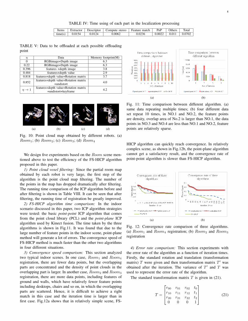
(a) (b) (c) (d)
Fig. 10: Point cloud map obtained by different robots. (a)Room1; (b) Room2; (c) Room3; (d) Room4
We design five experiments based on the Room scene men-tioned above to test the efficiency of the FS-HICP algorithmproposed in this paper.
1) Point cloud voxel filtering: Since the partial room mapobtained by each robot is very large, the first step of thealgorithm is the point cloud map filtering. The number ofthe points in the map has dropped dramatically after filtering.The running time comparison of the ICP algorithm before andafter filtering is shown in Table VIII. It can be seen that afterfiltering, the running time of registration be greatly improved.
2) FS-HICP algorithm time comparison: In the indoorscenario discussed in this paper, two ICP algorithm strategieswere tested: the basic point-point ICP algorithm that comesfrom the point cloud library (PCL) and the point-plane ICPalgorithm used by Kinect fusion. The time taken by the threealgorithms is shown in Fig.11. It was found that due to thelarge number of feature points in the indoor scene, point-planemethod will generate a lot of errors. The convergence speed ofFS-HICP method is much faster than the other two algorithmsin four different situations.
3) Convergence speed comparison: This section analyzedtwo typical indoor scenes. In one case, Room1 and Room4
registration, there are fewer data points, but the overlappingparts are concentrated and the density of point clouds in theoverlapping part is larger. In another case, Room2 and Room3
registration, there are more data points, including features ofground and walls, which have relatively fewer feature pointsincluding desktops, chairs and so on, in which the overlappingparts are scattered. Hence, it is difficult to achieve a rightmatch in this case and the iteration time is larger than infirst case. Fig.12a shows that in relatively simple scene, FS-
(a) (b)
Fig. 11: Time comparison between different algorithm. (a)same data repeating multiple times; (b) four different dataset repeat 10 times, in NO.1 and NO.2, the feature pointsare density, overlap area of No.2 is larger than NO.1, the datapoints in NO.3 and NO.4 are less than NO.1 and NO.2, featurepoints are relatively sparse.
HICP algorithm can quickly reach convergence. In relativelycomplex scene, as shown in Fig.12b, the point-plane algorithmcannot get a satisfactory result, and the convergence rate ofpoint-point algorithm is slower than FS-HICP algorithm.
(a) (b)
Fig. 12: Convergence rate comparison of three algorithms.(a) Room1 and Room4 registration; (b) Room2 and Room3
registration
4) Error rate comparison: This section experiments withthe error rate of the algorithm as a function of iteration times.Firstly, the standard rotation and translation (transformationmatrix) T were given and then transformation matrix T ′ wasobtained after the iteration. The variance of T ′ and T wasused to represent the error rate of the algorithm.
The standard transformation matrix T is given in (21).
T =
r00 r01 r02 t0r10 r11 r12 t1r20 r21 r22 t20 0 0 1
(21)
9
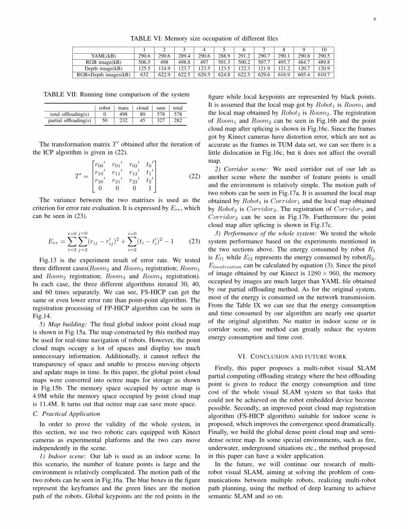
TABLE VI: Memory size occupation of different files
1 2 3 4 5 6 7 8 9 10YAML(kB) 290.6 290.6 289.4 290.6 288.9 291.2 290.7 290.1 290.8 290.5
RGB image(kB) 506.5 498 498.8 497 501.3 500.2 507.7 495.7 484.7 489.8Depth image(kB) 125.5 124.9 123.7 123.5 123.5 122.3 121.9 121.2 120.7 120.9
RGB+Depth images(kB) 632 622.9 622.5 620.5 624.8 622.5 629.6 616.9 605.4 610.7
TABLE VII: Running time comparison of the system
robot trans cloud sum totaltotal offloading(s) 0 498 80 578 578
partial offloading(s) 50 232 45 327 282
The transformation matrix T ′ obtained after the iteration ofthe ICP algorithm is given in (22).
T ′ =
r00′ r01
′ r02′ t0
′
r10′ r11
′ r12′ t1
′
r20′ r21
′ r22′ t2
′
0 0 0 1
(22)
The variance between the two matrixes is used as thecriterion for error rate evaluation. It is expressed by Err, whichcan be seen in (23).
Err =
i=0∑i=2
j=0∑j=2
(rij − r′ij)2 +i=0∑i=2
(ti − t′i)2 − 1 (23)
Fig.13 is the experiment result of error rate. We testedthree different cases(Room2 and Room3 registration; Room1
and Room2 registration; Room3 and Room4 registration).In each case, the three different algorithms iterated 30, 40,and 60 times separately. We can see, FS-HICP can get thesame or even lower error rate than point-point algorithm. Theregistration processing of FP-HICP algorithm can be seen inFig.14.
5) Map building: The final global indoor point cloud mapis shown in Fig.15a. The map constructed by this method maybe used for real-time navigation of robots. However, the pointcloud maps occupy a lot of spaces and display too muchunnecessary information. Additionally, it cannot reflect thetransparency of space and unable to process moving objectsand update maps in time. In this paper, the global point cloudmaps were converted into octree maps for storage as shownin Fig.15b. The memory space occupied by octree map is4.9M while the memory space occupied by point cloud mapis 11.4M. It turns out that octree map can save more space.C. Practical Application
In order to prove the validity of the whole system, inthis section, we use two robotic cars equipped with Kinectcameras as experimental platforms and the two cars moveindependently in the scene.
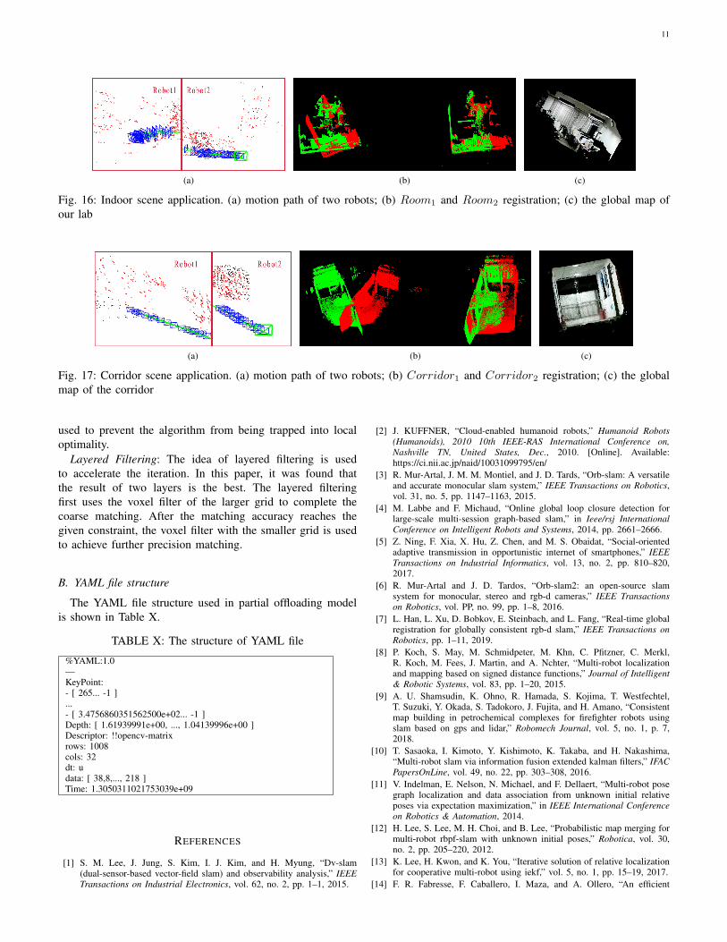
1) Indoor scene: Our lab is used as an indoor scene. Inthis scenario, the number of feature points is large and theenvironment is relatively complicated. The motion path of thetwo robots can be seen in Fig.16a. The blue boxes in the figurerepresent the keyframes and the green lines are the motionpath of the robots. Global keypoints are the red points in the
figure while local keypoints are represented by black points.It is assumed that the local map got by Robot1 is Room1 andthe local map obtained by Robot2 is Room2. The registrationof Room1 and Room2 can be seen in Fig.16b and the pointcloud map after splicing is shown in Fig.16c. Since the framesgot by Kinect cameras have distortion error, which are not asaccurate as the frames in TUM data set, we can see there is alittle dislocation in Fig.16c, but it does not affect the overallmap.
2) Corridor scene: We used corridor out of our lab asanother scene where the number of feature points is smalland the environment is relatively simple. The motion path oftwo robots can be seen in Fig.17a. It is assumed the local mapobtained by Robot1 is Corridor1 and the local map obtainedby Robot2 is Corridor2. The registration of Corridor1 andCorridor2 can be seen in Fig.17b. Furthermore the pointcloud map after splicing is shown in Fig.17c.
3) Performance of the whole system: We tested the wholesystem performance based on the experiments mentioned inthe two sections above. The energy consumed by robot R1
is El1 while El2 represents the energy consumed by robotR2.Elocalization can be calculated by equation (3). Since the pixelof image obtained by our Kinect is 1280× 960, the memoryoccupied by images are much larger than YAML file obtainedby our partial offloading method. As for the original system,most of the energy is consumed on the network transmission.From the Table IX we can see that the energy consumptionand time consumed by our algorithm are nearly one quarterof the original algorithm. No matter in indoor scene or incorridor scene, our method can greatly reduce the systemenergy consumption and time cost.
VI. CONCLUSION AND FUTURE WORK
Firstly, this paper proposes a multi-robot visual SLAMpartial computing offloading strategy where the best offloadingpoint is given to reduce the energy consumption and timecost of the whole visual SLAM system so that tasks thatcould not be achieved on the robot embedded device becomepossible. Secondly, an improved point cloud map registrationalgorithm (FS-HICP algorithm) suitable for indoor scene isproposed, which improves the convergence speed dramatically.Finally, we build the global dense point cloud map and semi-dense octree map. In some special environments, such as fire,underwater, underground situations etc., the method proposedin this paper can have a wider application.
In the future, we will continue our research of multi-robot visual SLAM, aiming at solving the problem of com-munications between multiple robots, realizing multi-robotpath planning, using the method of deep learning to achievesemantic SLAM and so on.
10
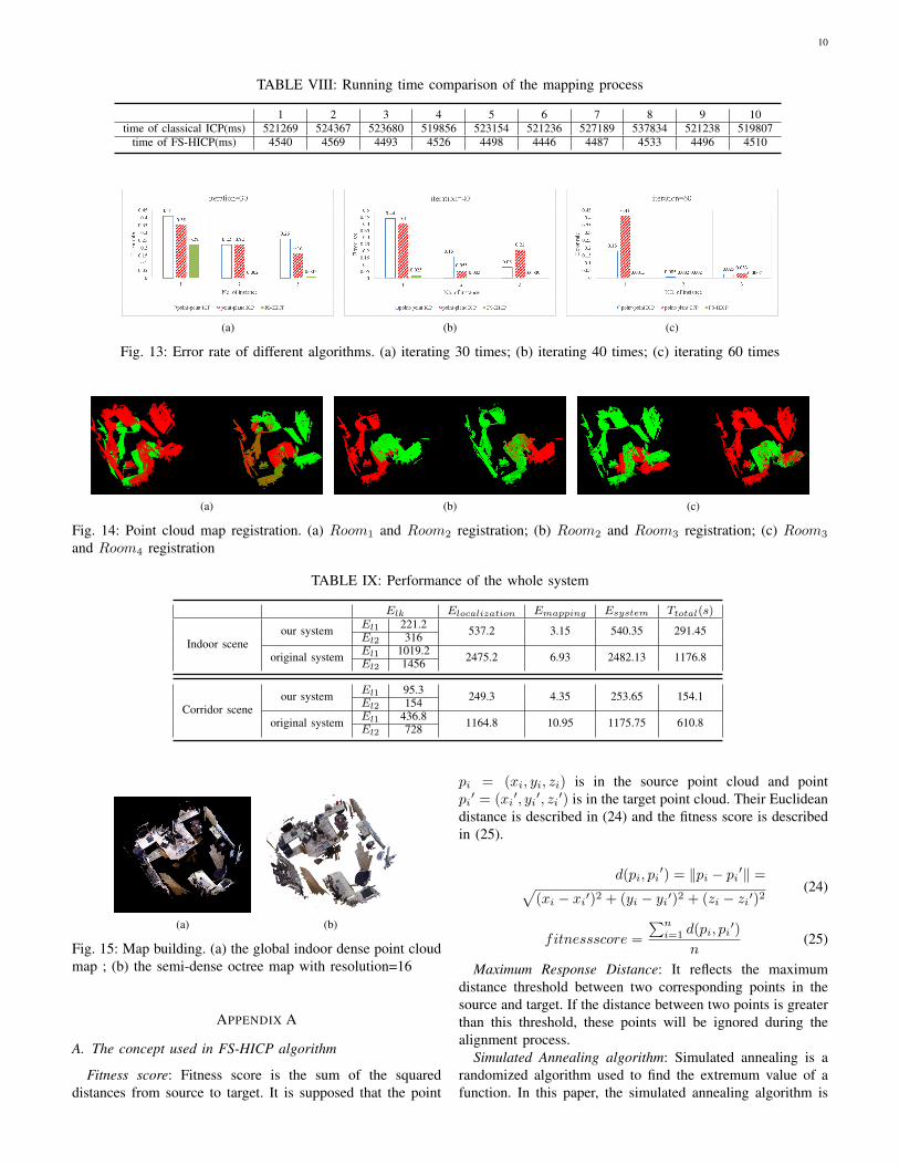
TABLE VIII: Running time comparison of the mapping process
1 2 3 4 5 6 7 8 9 10time of classical ICP(ms) 521269 524367 523680 519856 523154 521236 527189 537834 521238 519807
time of FS-HICP(ms) 4540 4569 4493 4526 4498 4446 4487 4533 4496 4510
(a) (b) (c)
Fig. 13: Error rate of different algorithms. (a) iterating 30 times; (b) iterating 40 times; (c) iterating 60 times
(a) (b) (c)
Fig. 14: Point cloud map registration. (a) Room1 and Room2 registration; (b) Room2 and Room3 registration; (c) Room3
and Room4 registration
TABLE IX: Performance of the whole system
Elk Elocalization Emapping Esystem Ttotal(s)
Indoor sceneour system El1 221.2 537.2 3.15 540.35 291.45
El2 316
original system El1 1019.2 2475.2 6.93 2482.13 1176.8El2 1456
Corridor sceneour system El1 95.3 249.3 4.35 253.65 154.1
El2 154
original system El1 436.8 1164.8 10.95 1175.75 610.8El2 728
(a) (b)
Fig. 15: Map building. (a) the global indoor dense point cloudmap ; (b) the semi-dense octree map with resolution=16
APPENDIX A
A. The concept used in FS-HICP algorithm
Fitness score: Fitness score is the sum of the squareddistances from source to target. It is supposed that the point
pi = (xi, yi, zi) is in the source point cloud and pointpi′ = (xi
′, yi′, zi′) is in the target point cloud. Their Euclidean
distance is described in (24) and the fitness score is describedin (25).
d(pi, pi′) = ‖pi − pi′‖ =√
(xi − xi′)2 + (yi − yi′)2 + (zi − zi′)2(24)
fitnessscore =
∑ni=1 d(pi, pi
′)
n(25)
Maximum Response Distance: It reflects the maximumdistance threshold between two corresponding points in thesource and target. If the distance between two points is greaterthan this threshold, these points will be ignored during thealignment process.
Simulated Annealing algorithm: Simulated annealing is arandomized algorithm used to find the extremum value of afunction. In this paper, the simulated annealing algorithm is
11
(a) (b) (c)
Fig. 16: Indoor scene application. (a) motion path of two robots; (b) Room1 and Room2 registration; (c) the global map ofour lab
(a) (b) (c)
Fig. 17: Corridor scene application. (a) motion path of two robots; (b) Corridor1 and Corridor2 registration; (c) the globalmap of the corridor
used to prevent the algorithm from being trapped into localoptimality.
Layered Filtering: The idea of layered filtering is usedto accelerate the iteration. In this paper, it was found thatthe result of two layers is the best. The layered filteringfirst uses the voxel filter of the larger grid to complete thecoarse matching. After the matching accuracy reaches thegiven constraint, the voxel filter with the smaller grid is usedto achieve further precision matching.
B. YAML file structure
The YAML file structure used in partial offloading modelis shown in Table X.
TABLE X: The structure of YAML file
%YAML:1.0—KeyPoint:- [ 265... -1 ]...- [ 3.4756860351562500e+02... -1 ]Depth: [ 1.61939991e+00, ..., 1.04139996e+00 ]Descriptor: !!opencv-matrixrows: 1008cols: 32dt: udata: [ 38,8,..., 218 ]Time: 1.3050311021753039e+09
REFERENCES
[1] S. M. Lee, J. Jung, S. Kim, I. J. Kim, and H. Myung, “Dv-slam(dual-sensor-based vector-field slam) and observability analysis,” IEEETransactions on Industrial Electronics, vol. 62, no. 2, pp. 1–1, 2015.
[2] J. KUFFNER, “Cloud-enabled humanoid robots,” Humanoid Robots(Humanoids), 2010 10th IEEE-RAS International Conference on,Nashville TN, United States, Dec., 2010. [Online]. Available:https://ci.nii.ac.jp/naid/10031099795/en/
[3] R. Mur-Artal, J. M. M. Montiel, and J. D. Tards, “Orb-slam: A versatileand accurate monocular slam system,” IEEE Transactions on Robotics,vol. 31, no. 5, pp. 1147–1163, 2015.
[4] M. Labbe and F. Michaud, “Online global loop closure detection forlarge-scale multi-session graph-based slam,” in Ieee/rsj InternationalConference on Intelligent Robots and Systems, 2014, pp. 2661–2666.
[5] Z. Ning, F. Xia, X. Hu, Z. Chen, and M. S. Obaidat, “Social-orientedadaptive transmission in opportunistic internet of smartphones,” IEEETransactions on Industrial Informatics, vol. 13, no. 2, pp. 810–820,2017.
[6] R. Mur-Artal and J. D. Tardos, “Orb-slam2: an open-source slamsystem for monocular, stereo and rgb-d cameras,” IEEE Transactionson Robotics, vol. PP, no. 99, pp. 1–8, 2016.
[7] L. Han, L. Xu, D. Bobkov, E. Steinbach, and L. Fang, “Real-time globalregistration for globally consistent rgb-d slam,” IEEE Transactions onRobotics, pp. 1–11, 2019.
[8] P. Koch, S. May, M. Schmidpeter, M. Khn, C. Pfitzner, C. Merkl,R. Koch, M. Fees, J. Martin, and A. Nchter, “Multi-robot localizationand mapping based on signed distance functions,” Journal of Intelligent& Robotic Systems, vol. 83, pp. 1–20, 2015.
[9] A. U. Shamsudin, K. Ohno, R. Hamada, S. Kojima, T. Westfechtel,T. Suzuki, Y. Okada, S. Tadokoro, J. Fujita, and H. Amano, “Consistentmap building in petrochemical complexes for firefighter robots usingslam based on gps and lidar,” Robomech Journal, vol. 5, no. 1, p. 7,2018.
[10] T. Sasaoka, I. Kimoto, Y. Kishimoto, K. Takaba, and H. Nakashima,“Multi-robot slam via information fusion extended kalman filters,” IFACPapersOnLine, vol. 49, no. 22, pp. 303–308, 2016.
[11] V. Indelman, E. Nelson, N. Michael, and F. Dellaert, “Multi-robot posegraph localization and data association from unknown initial relativeposes via expectation maximization,” in IEEE International Conferenceon Robotics & Automation, 2014.
[12] H. Lee, S. Lee, M. H. Choi, and B. Lee, “Probabilistic map merging formulti-robot rbpf-slam with unknown initial poses,” Robotica, vol. 30,no. 2, pp. 205–220, 2012.
[13] K. Lee, H. Kwon, and K. You, “Iterative solution of relative localizationfor cooperative multi-robot using iekf,” vol. 5, no. 1, pp. 15–19, 2017.
[14] F. R. Fabresse, F. Caballero, I. Maza, and A. Ollero, “An efficient

12
approach for undelayed range-only slam based on gaussian mixturesexpectation ,” Robotics & Autonomous Systems, vol. 104, 2018.
[15] Y. Isobe, G. Masuyama, and K. Umeda, “Occlusion handling for a target-tracking robot with a stereo camera,” Robomech Journal, vol. 5, no. 1,p. 4, 2018.
[16] M. Nowicki, D. Belter, A. Kostusiak, P. ?ł?ek, J. Faigl, andP. Skrzypczynski, “An experimental study on feature-based slam formulti-legged robots with rgb-d sensors,” Industrial Robot, vol. 44, no. 4,2017.
[17] R. Arumugam, V. R. Enti, B. Liu, X. Wu, K. Baskaran, F. F. Kong,A. S. Kumar, K. D. Meng, and G. W. Kit, “Davinci: A cloud computingframework for service robots,” in IEEE International Conference onRobotics and Automation, 2010, pp. 3084–3089.
[18] D. Hunziker, M. Gajamohan, M. Waibel, and R. D’Andrea, “Rapyuta:The roboearth cloud engine,” in IEEE International Conference onRobotics and Automation, 2013, pp. 438–444.
[19] L. Ma, J. Zhu, L. Zhu, S. Du, and J. Cui, “Merging grid maps of differentresolutions by scaling registration,” Robotica, vol. 34, no. 11, pp. 2516–2531, 2016.
[20] J. Yang, H. Li, D. Campbell, and Y. Jia, “Go-icp: A globally optimalsolution to 3d icp point-set registration,” IEEE Transactions on PatternAnalysis & Machine Intelligence, vol. 38, no. 11, pp. 2241–2254, 2016.
[21] R. Marani, V. Ren, M. Nitti, T. D’Orazio, and E. Stella, “A modified iter-ative closest point algorithm for 3d point cloud registration,” Computer-Aided Civil and Infrastructure Engineering, vol. 31, no. 7, pp. 515–534,2016.
[22] M. Magnusson, A. J. Lilienthal, and T. Duckett, Scan registration forautonomous mining vehicles using 3D-NDT. John Wiley and Sons Ltd.,2007.
[23] R. A. Newcombe, S. Izadi, O. Hilliges, D. Molyneaux, D. Kim, A. J.Davison, P. Kohli, J. Shotton, S. Hodges, and A. W. Fitzgibbon,“Kinectfusion: Real-time dense surface mapping and tracking,” in IEEEInternational Symposium on Mixed and Augmented Reality, 2012, pp.127–136.
[24] M. Torkashvan and H. Haghighi, “Cslam: A framework for cloud servicelevel agreement management based on wsla,” in Sixth InternationalSymposium on Telecommunications, 2012.
[25] P. Benavidez, M. Muppidi, P. Rad, J. J. Prevost, J. Mo, and L. Brown,“Cloud-based realtime robotic visual slam,” in Systems Conference,2015.
[26] P. J. Besl and N. D. Mckay, “Method for registration of 3-d shapes,”IEEE Transactions on Pattern Analysis & Machine Intelligence, vol. 14,no. 2, pp. 239–256, 1992.
[27] K. Kumar and Y. Lu, “Cloud computing for mobile users: Can offloadingcomputation save energy?” Computer, vol. 43, no. 4, pp. 51–56, April2010.
[28] P. Zhang, H. Wang, B. Ding, and S. Shang, “Cloud-based frameworkfor scalable and real-time multi-robot slam,” in 2018 IEEE InternationalConference on Web Services (ICWS), July 2018, pp. 147–154.
[29] F. Okumu? and A. Fatih, “Exploring the feasibility of a multifunctionalsoftware platform for cloud robotics,” in 2018 International Conferenceon Artificial Intelligence and Data Processing (IDAP), Sep. 2018, pp.1–4.