part ii model commissioning plan --design phase--€¦ · part ii model commissioning plan --design...
TRANSCRIPT

Part II
Model Commissioning Plan --Design Phase--
Initially Sponsored (Ver. 2.04) by US Department of Energy
Seattle Regional Support Office 800 5th Ave. Suite 3950
Seattle, WA 98104
Version 2.05 Modifications Sponsored by Oregon Office of Energy
625 Marion Street NE Salem, OR 97310
and Portland Energy Conservation, Inc.
Prepared by:
Portland Energy Conservation, Inc. (PECI) 921 SW Washington, Suite 312
Portland, OR 97205 503-248-4636, Fax 503-295-0820
Version 2.05
February 1998
Version 2.04 was distributed by PECI in 1997 and by USDOE in 1998, with USDOE referenced in the footer of each file. Since that version, changes and additions have been made by PECI without review by USDOE; subsequently in
Version 2.05 the reference to USDOE has been removed from the footers.
IMPORTANT NOTICE: This sample document is provided for instructional purposes only. CCC is not rendering advice concerning any commission project or practices. This document is neither approved nor intended to serve as a standard form. The user of these documents should confer with qualified advisors with respect to its commissioning and other documentation.

Part II. Model Commissioning Plan−Design Phase Contents & Instructions
Part II
Model Commissioning Plan --Design Phase--
Summary
The Model Commissioning Plan—Design Phase guides the commissioning activities during the design phase. It provides details of responsibilities called out in Part I, Commissioning Requirements—Design Phase for the architect, design engineers, commissioning authority, construction and project managers. The plan describes the duties of the A/E team and commissioning authority in developing the site-specific commissioning specifications and for developing the first two drafts of the Commissioning Plan—Construction Phase.
Table of Contents
Instructions for the Owner Filling Out the Model Commissioning Plan—Design Phase ii
Using the Plan with the RFP ii
Instructions for Filling Out the Model Plan ii
Commissioning Plan—Design Phase 1
1. Overview of Commissioning During Design 1
2. Building Information 1
3. Design Project Team Data 3
4. Responsibilities 4 Tasks 4 Scope 4 Reporting 4
5. Commissioning Scope of Work 6 5.1 Task 1. Coordination of Commissioning During Design 6 5.2 Task 2. Design Phase Commissioning Plan 6 5.3 Task 3. Design Development Review 7 5.4 Task 4. Design Intent and Basis of Design Documentation 8 5.5 Task 5. Draft Commissioning Plan for Construction 12 5.6 Task 6. Commissioning Specification Development 12 5.7 Task 7. General Review of Drawings and Specifications 13 5.8 Commissioning Facilitation 16
6. General Schedule 16
Appendix 1. Commissioning for Indoor Quality Checklist--Design Phase Appendix 2. Sample Fire and Emergency Power Response Matrix
Model Commissioning Plan and Guide Specifications © 2005, Portland Energy Conservation, Inc. (PECI). All rights reserved.
i

Part II. Model Commissioning Plan−Design Phase Contents & Instructions
Instructions for the Owner Filling Out the Model Commissioning Plan—Design Phase
Using the Plan with the RFP The Model Commissioning Plan—Design Phase should be used for obtaining design proposals which will include commissioning and to guide the commissioning work throughout the design process. The Design Phase Commissioning Plan is referred to as the Model plan when it is not yet filled out. Refer to the Overview of the entire Model Commissioning Plan and Guide Specifications for further instructions about using the plan during the design process.
Instructions for Filling Out the Model Plan With the following directions, the owner’s staff can confidently fill out the Model Plan and RFP Requirements. The awarded commissioning authority or architect will later revise the plan as necessary. The Model Plan is intended as a true “boilerplate” for most projects and can be filled out by hand without any attachments. For projects with unusual contracting arrangements, editing the Model Plan may be necessary, and is provided on electronic media.
First fill out Section 2, Building Information, to provide the expected magnitude of the project in gross terms. Section 3 will not be filled out until the design contract is awarded.
Next, skip to Section 5, Commissioning Scope of Work. Here, the first decision to be made is to decide which systems will be commissioned. At a minimum, the HVAC, HVAC control system and lighting controls should be commissioned. Consulting with other project managers, your own experience and budget considerations will help you decide on the others.
Next, under Task 1 of Section 5, Overall Coordination, decide whether the architect or the commissioning authority will coordinate the commissioning during design. The commissioning authority is generally a good choice to start with, but in some design teams the architect may be the better party, especially where the architect is more than just casually interested in commissioning, or where, with the commissioning authority as the coordinator, not enough support will be given to the commissioning authority from the other members of the team. Your decision can always be changed after the award of the contract.
Generally the formal commissioning should start at the beginning of the Design Development Phase. For smaller, less complex projects, the commissioning effort could wait until the beginning of the Construction Documents Phase.
Next, under Task 3 of Section 5, Design Development Review, decide how much, if any, the commissioning authority will review the design at the end of Design Development. This is highly recommended. The number of design areas the commissioning authority reviews is dependent on the commissioning authority’s skills and the emphasis and interest by the owner and the tenants in particular areas. At a minimum, the commissioning authority should review the energy-efficiency, operations and maintenance and the indoor environmental quality issues. Desired areas for review should be checked in Table 5-1.
Under Task 4 of Section 5, Develop Design Documentation, decide for which systems the designers will provide documented detailed design intent and operational parameters. Generally, all of the listed areas are highly recommended. Also under Task 4, who will coordinate the development of the design intent documentation—the commissioning authority or the architect— must be determined. Either party should work well. The desired areas for documentation should be checked.
Model Commissioning Plan and Guide Specifications © 2005, Portland Energy Conservation, Inc. (PECI). All rights reserved.
ii

Part II. Model Commissioning Plan−Design Phase Contents & Instructions
Task 5 of Section 5, Develop Construction Phase Commissioning Plan, requires no input, unless there are areas in the as-is Model Commissioning Plan—Construction Phase (Part IV) that the owner does not want to include. If so, the exclusions should be footnoted under this task.
Task 6 of Section 5, Develop Commissioning Specifications, requires no input at this time, unless there are large significant areas of the Guide Specifications (Part III) that the owner wants changed or clarified now, rather than during the normal adaptation process. If so, these exclusions or clarifications should be given under Task 6. It is noted that the Guide Specifications are not intended to be totally applicable to the project at hand and that the job of the design team is to adapt them. Thus, most or all of the changes needed will be made during the design process with guidance and approval of the owner.
Task 7 of Section 5, Conduct a Final Design Review, requires similar input as Task 3, using Table 5-3.
The Commissioning Schedule in Section 6 is fairly universal and will generally require no input. The only change that might be needed is if the commissioning starts later than the beginning of Design Development.
Finally, go to Table 4-1 in Section 4. This is a one-page view of the commissioning roles and responsibilities of the design team. In Table 4-1, there are two areas requiring input: 1) Who the overall commissioning coordinator during design will be, and 2) Who the lead on Task 4 will be. Check the appropriate party for these tasks and verify the other checks.
Model Commissioning Plan and Guide Specifications © 2005, Portland Energy Conservation, Inc. (PECI). All rights reserved.
iii

Part II. Model Commissioning Plan−Design Phase
Commissioning Plan—Design Phase
Project: _____________________________ _____________________________ Owner Contact: _____________________________ Date: ________________
1. Overview of Commissioning During Design Commissioning (Cx) is a systematic process of ensuring that all building systems perform interactively according to the design intent and the owner’s operational needs. This is achieved by beginning in the design phase and documenting design and operating intent and continuing through construction and acceptance with actual verification of performance.
Commissioning during design is intended to achieve the following specific objectives:
• Provide commissioning focused design review. • Ensure that the design and operational intent are clearly documented. • Ensure that commissioning for the construction phase is adequately reflected in the bid documents.
The commissioning process during design is illustrated in Figure 1-1.
For reference, a brief description of the Owner design phases follows. Refer to the Part I, Commissioning Requirements−Design Phase for a listing of party definitions.
Programming—Design team and the Owner Project Manager meet with representatives of the occupying agency or client and determine the square footage and occupancy requirements of the building.
Conceptual Design Phase–Architect develops block diagrams, building sizing, rough space planning and sketches of exterior types. Multiple choices are provided. Mechanical and electrical designers generally have no input in this phase.
Design Development Phase–Additional detail is applied to the block diagrams and layouts. Interior and exterior features and finishes and general HVAC system types are determined and a rough floor plan is approved. Value engineering, if any, is completed.
Construction Documents Phase–Drawings are completed. Specifications are completed, generally using the Owner’s Master Spec. Bid documents are prepared.
2. Building Information Project Name: ________________________________________________________________
Location: ____________________________________________________________________
Building Type (office, court, etc.): _________________________________________________
Square Footage: Expected number of stories: ___________________________
Agency: Tenants: ___________________________________________
Design Period: Const. Period: ______________________________________
Model Commissioning Plan and Guide Specifications 1 PECI 02_Model_Cx_Plan_DesignPhase_PECI.doc, 4/22/2005

Part II. Model Commissioning Plan−Design Phase
Figure 1-1. Commissioning During Design
Owner Develops a Request forDesign Services
Conceptual design
Owner Enters Into a Contractwith a Design Team
Programming Phase
Owner Adapts Model Cx Plan and DesignTeam Cx Requirements to this Project
Construction Documents
DrawingsSpecifications
Bid Documents
Review at 50%Review at 95%
Design Development
Block LayoutsSystem Descriptions
Review
CA HiredCommissioning Plan Finalized
Commissioning Kick-Off Meeting
Design Team Submits Design IntentDocumentation-CA Reviews
CA reviews Design Development
CA Reviews Work at 50%
Design Team Submits Full Design IntentCA Reviews
CA Develops Draft CommissioningPlan-Construction Phase
Construction CommissioningSpecifications Developed-CA Reviews
CA Reviews Work at 95%
Owner Conventional Activities Commissioning Activities
Model Commissioning Plan and Guide Specifications 2 PECI 02_Model_Cx_Plan_DesignPhase_PECI.doc, 4/22/2005

Part II. Model Commissioning Plan−Design Phase
3. Design Project Team Data
Project Manager
Name: Company:
Voice Ofc: Cell:
Fax: Email:
Address:
Commissioning Authority (CA)
Name: Company:
Voice Ofc: Cell:
Fax: Email:
Address:
Architect
Names: Company:
Voice Ofc: Cell:
Fax: Email:
Address:
HVAC Mechanical Designer
Name: Company:
Voice0 Ofc: Cell:
Fax: Email:
Address:
Electrical Designer
Name: Company:
Voice Ofc: Cell:
Fax: Email:
Address:
Construction Manager
Name: Company:
Voice Ofc: Cell:
Fax: Email:
Address:
Tenant Representative
Name: Company:
Voice Ofc: Cell:
Fax: Email:
Address:
Name: Company:
Voice Ofc: Cell:
Fax: Email:
Address:
Model Commissioning Plan and Guide Specifications 3 PECI 02_Model_Cx_Plan_DesignPhase_PECI.doc, 4/22/2005

Part II. Model Commissioning Plan−Design Phase
4. Responsibilities
Tasks A list of the responsibilities and tasks for each party of the design team are presented in Table 4-1. The member assigned as the lead for a given task is shown. The lead will coordinate the completion of the task. Under each task listing are subtasks with an “X” marked by the participating team members. The tenant representative(s) are considered members of the design team and will contribute in their normal fashion. They have no new role in the commissioning effort and so are not listed in the table.
Scope Section 5 provides additional detail regarding scope of the tasks.
Reporting Members completing subtasks report to the lead for that task, per Table 4-1. The task lead reports to the Coordinator lead (the lead in Task 1).
Model Commissioning Plan and Guide Specifications 4 PECI 02_Model_Cx_Plan_DesignPhase_PECI.doc, 4/22/2005

Part II. Model Commissioning Plan−Design Phase
Table 4-1. Commissioning Roles and Responsibilities During Design Parties Involved
Task Design Phase
Commissioning Responsibilities and Tasks Com
mis
sion
ing
Aut
horit
y
Arc
hite
ct
Mec
hani
cal
Des
igne
r (H
VA
C)
Ele
ctric
al
Des
igne
r P
roje
ct
Man
ager
Con
st.
Man
ager
1 Overall coordination of the Cx work during Design Lead-->a. Plan and schedule meetings X X Xb. See that all tasks are carried out X X Xc.
2 Finalize the Cx plan for Design Phase Lead--> Xa. Edit the original Cx Plan as necessary Xb. Review and comment on Cx plan X Xc.
3 Perform design development review [1] Lead--> Xa. After completion of Design Development, review design concepts of the areas checked in Table 5-1.
X -- -- -- --
b. Respond to CA review comments X X X
4 Develop design & operating intent documentation Lead-->a. Provide design intent format and assistance Xb. Write design intent for systems checked under Task 4 in Section 5. X X X Xc. Review and approve design intent for clarity and completeness X Xd. Respond to CA review comments X X X
5 Develop draft Cx plan for Construction Phase Lead--> Xa. Adapt and edit the Model Cx Plan--Const. Phase, Draft 1 and 2 Xb. Review Cx plan X Xc.
6 Develop Cx specifications for construction Lead--> Xa. Assist in, review & approve all sections X Xb. Adapt Cx guide specs & include in Division 1 X Xc. Adapt Cx guide specs & include in Division 15 (HVAC) Xd. Adapt Cx guide specs & include in Division 16 (electrical) Xe. Adapt Cx guide specs in special Cx Division ____ Xf. Adapt Cx guide specs & include in Division ___g.
7 Review final drawings and specifications [1] Lead--> Xa. Review full drawings & specifications at ~50% & ~95% complete to ensure that the design intent is met (see Table 5-3).
X -- -- -- -- --
b. Respond to CA review comments X X X[1] Lead team member for this task is circled. Enter percentages to provide the approximate fraction of work by each party forthe whole task; enter an "X" in the sub-tasks for participants. [2] This does not preclude the normal reviews by all parties, denoted by a dash--, but is intended to show the addedreview by the commissioning agent.
Model Commissioning Plan and Guide Specifications 5 PECI 02_Model_Cx_Plan_DesignPhase_PECI.doc, 4/22/2005

Part II. Model Commissioning Plan−Design Phase
5. Commissioning Scope of Work The following checked systems will be commissioned in this project:
___HVAC system (virtually all equipment) ___HVAC system (primary equipment only) ___HVAC energy management control system ___Indoor air quality (moderate level of effort) ___Indoor air quality (rigorous level of effort) ___Automatic Lighting controls ___Electrical system power quality, grounding, etc. ___Emergency power system and integration issues ___Communications system, e.g., ___________________________________________ ___Security system ___Fire/smoke alarm and control system and integration issues ___Plumbing systems ___Telecommunications and data systems ___ _______________________________ ___ _______________________________
The following tasks comprise the commissioning work during design:
1. Coordinate the commissioning activities 2. Finalize design phase commissioning plan 3. Perform a review of Design Development 4. Develop design intent documentation 5. Develop the draft commissioning plan for the construction phase 6. Develop commissioning specifications for the construction bid documents 7. Perform a final review of the drawings and specifications
A listing of these tasks with the parties involved with them is included in Table 4-1. Each of the tasks in Table 4-1 will be executed unless specifically noted otherwise.
5.1 Task 1. Coordination of Commissioning During Design The ___commissioning authority, ___architect will be the coordinator of the commissioning activities during design, per the designations in Table 4-1. The beginning of this task consists of holding a kick-off meeting with the design team at the beginning of ___Conceptual Design Phase, ___Design Development Phase, ___Construction Documents Phase. This meeting is held after the Cx Plan has been finalized (Task 2). The meeting includes reviewing the process and outlining each party’s responsibilities.
The coordinator will ensure that commissioning issues are part of design team meeting agendas and will ensure that the Leads for each task understand their responsibilities and execute them. The coordinator makes any necessary changes to the design phase Commissioning Plan provided by the to the A/E team during the proposal process (Task 2). The coordinator reports to the architect and to the Project Manager.
5.2 Task 2. Design Phase Commissioning Plan The commissioning coordinator for the design phase (Task 1) makes any necessary clarifications and changes to the original design phase Commissioning Plan provided by the Owner at the RFP stage and
Model Commissioning Plan and Guide Specifications 6 PECI 02_Model_Cx_Plan_DesignPhase_PECI.doc, 4/22/2005

Part II. Model Commissioning Plan−Design Phase
submits it to the architect and Project Manager for approval. This final plan guides the commissioning work during design. Necessary adjustments to the design team’s fees relative to Commissioning Plan changes are negotiated. All design team members receive a copy of the plan from the coordinator.
5.3 Task 3. Design Development Review At the end of Design Development, the commissioning authority ___reviews, ___does not review the design along with the other design team members. If the commissioning authority does not perform this review, the rest of this section does not apply, otherwise:
The commissioning authority compares the design with the interests and needs of the Owner as identified in the programming report of the Programming and Conceptual Design Phases. The commissioning authority also compares the proposed design against the Owner’s design guide for the design areas checked. The commissioning authority also identifies any improvements that can be made in areas checked below. Though the commissioning authority may review the areas checked below, they are not responsible for design concept, design criteria or compliance with codes.
Table 5-1. Commissioning Authority Design Development Review
Design Area Review Description
___ Commissioning facilitation Input regarding making the building easier to commission (see Commissioning Facilitation under Section 5.7)
___ Energy Efficiency General efficiency of building shell, building layout, HVAC system types, lighting system type, etc.
___ Operation and Maintenance (O&M). How building O&M can be made easier (accessibility and system control, etc.)
___ Indoor Environmental Quality (IEQ) How thermal, visual, acoustical comfort or air quality1 can be improved
___ Functionality for Tenants How the design can be changed to improve functionality for the occupants
___ Environmental Sustainability How the building materials and systems and landscaping can create less of an impact on the environment
___ Life Cycle Costs Life cycle assessment of options relative to energy efficiency, O&M, IEQ or functionality
1 To perform this review, the commissioning authority, in consultation with the owner to establish scope, shall use the checklists provided in Appendix 1. Indoor air quality (IAQ) commissioning does not ensure that indoor air quality will be adequate or without deficiency at building turnover or during occupancy, unless the owner has specifically specified that actual air quality testing is performed. Commissioning indoor air quality entails performing tasks that minimize the potential for IAQ problems, but it does not eliminate their possibility.
This review is documented in writing and submitted to the design phase commissioning coordinator and forwarded to the architect and Project Manager. The architect distributes the comments to the design team members. The team members respond to the architect who provides a written response to the commissioning authority and to the Project Manager describing the team’s response and any changes or considerations made in the design.
Model Commissioning Plan and Guide Specifications 7 PECI 02_Model_Cx_Plan_DesignPhase_PECI.doc, 4/22/2005

Part II. Model Commissioning Plan−Design Phase
5.4 Task 4. Design Intent and Basis of Design Documentation Specifically identifying and developing the design intent and basis of design provides each party involved, at each respective stage, an understanding of the building systems. This allows team members to perform their respective responsibilities regarding the design, construction or operation of the building.
The design documentation differs from traditional specifications in that it provides a more narrative description of the system or issue and “frames” the issue or building component with clear and useful background information. However, design documentation often includes parts of specifications. In general, specifications detail what is to be done on a component level, while design documentation explains why something is done and, in general terms, how design and operating objectives will be accomplished. Sections of the design documentation can look like specifications, especially where tasks depart from conventional practice, e.g., energy-efficient design and construction.
Design documentation includes the salient information from the programming report, the conceptual design phase and from the design and construction process necessary to guide the design, verify compliance during construction and aid building operations. Design documentation consists of two components: design intent and the basis of design.
Design Intent The design intent is a document that provides the explanation of the ideas, concepts and criteria that are considered to be very important to the owner. It is initially the outcome of the programming and conceptual design phases. The design intent narrative should cover the following, for each system, major component, facility and area:
• Objectives and functional use for the issue, system, equipment or facility • General system description, if known • General quality of materials and construction • Occupancy requirements • Indoor environmental quality, IEQ (space temperature, relative humidity, indoor air quality , noise
level, illumination level, etc.) • Performance criteria (general efficiency, energy and tolerances of the IEQ objectives, etc.) • Budget considerations and limitations • Restrictions and limitations of system or facility
Many of the above topics may not be necessary for smaller components, such as VAV terminal units.
Basis of Design The basis of design is the dynamic documentation of the primary thought processes and assumptions behind design decisions that were made to meet the design intent. The basis of design describes the systems, components, conditions and methods chosen to meet the intent. Some reiterating of the design intent may be included. The following should be included in the basis of design for major equipment:
• Specific description of systems, components and methods for achieving the design intent objectives. (For example, for a rooftop air conditioning unit include: what system alternatives were considered and why was this one selected, details of size, efficiencies, areas served, capacity control details, compressors, coils, dampers, setpoints, filters, economizers, minimum ventilation control, control type, noise and vibration criteria, tie-in to other systems, sequences of operation under all modes of operation, control strategies, etc.)
• Equipment maintainability • Fire, life, safety: criteria, general strategy narrative and detailed sequences • Emergency power control and function
Model Commissioning Plan and Guide Specifications 8 PECI 02_Model_Cx_Plan_DesignPhase_PECI.doc, 4/22/2005

Part II. Model Commissioning Plan−Design Phase
• Energy performance • Ventilation strategies and methods • Complete sequences of operation, including setpoints and control parameters • Schedules • Applicable codes and standards • Primary load calculations including design and energy modeling assumptions
• Diversity used in sizing • Occupant density and function • Indoor conditions (space temperature, relative humidity, lighting power density, ventilation
and infiltration rates, etc.) • Outdoor conditions • Glazing fraction, U-value and shading coefficient • Wall and ceiling R-values Information of secondary importance to the commissioning and operation of the building should be documented by the design team, but is not included in the design documentation described here or included in the O&M manuals.
The detail of both the design intent and basis of design increase as the design process progresses, as described in Table 5-2. In the beginning, the design documentation required is primarily a narrative of the building system descriptions, the purpose of the systems, how the systems will meet those objectives and why this system or method was chosen above others. As the design process progresses, the design documentation includes the basis of design, a specific description of the system and components, its function, how it relates to other systems, sequences of operation, and operating control parameters. Each contributing designer clearly documents in writing the intent behind the chosen design and the operating parameters of the system. The design intent required here is not a substitute for what may be required in the specifications or contract for other systems.
Table 5-2. Progression of Design Documentation
Stage
Issues Addressed
Responsible Parties
Programming
The owner’s and tenant’s needs are identified in detail. The applicable parts of the programming report become the initial design intent.
Owner Architect
Conceptual Design and Design Dev.
Design intent clarified. Basis of design begun: overall system descriptions, objectives of systems, general methods of achieving objectives, etc.
Owner Architect
Construction Documents and Specification Development
Same as Conceptual Design and Design Dev. above, but in more detail, including complete basis of design: complete system & component description, specific methods of achieving system objectives, design & load assumptions, applicable codes and standards, complete sequences of operation and control strategies
Architect Design Engineers
As-Built Documentation
Same as Construction Documents and Specification Development, plus: Adjusted sequences with final control parameters
Design Engineers Installing Contractors Building Operator Architect
Model Commissioning Plan and Guide Specifications 9
PECI 02_Model_Cx_Plan_DesignPhase_PECI.doc, 4/22/2005

Part II. Model Commissioning Plan−Design Phase
The initial design intent from the programming phase is developed by the architect with review by the design team and commissioning authority. The architect, or other assigned party, acts as the design documentation task lead and coordinates the creation of the full design documentation by the design team. Each member of the team provides the system description, the written basis of design and detailed sequences of operation for the areas of design that are their responsibility. They submit the documentation in parts to the task lead at the pre-determined phases of design. The architect, task lead and commissioning authority review, comment on and approve the submissions. Design intent documentation for other components and systems such as structural, interior design, furnishings, plumbing, etc. may be required, but are not a part of the commissioning work unless listed and checked herein.
Design Documentation Submitted: By the Architect
___general building design and function ___interior lighting ___building shell efficiency ___environmental sustainable construction ___landscaping / irrigation ___ ______________________________________________ ___ ______________________________________________
By the HVAC Mechanical Designer/Engineer ___HVAC systems (air and water) ___automatic controls ___fire/smoke protection systems ___thermal comfort ___air quality ___acoustical quality ___ one-line CAD drawings of all mechanical systems including, but not limited to: the chilled and
hot water, condenser water, domestic water, steam and condensate systems; supply, return and exhaust air systems, medical gas system.
By the Electrical Designer/Engineer ___interior lighting ___automatic lighting controls (exterior and interior) ___security system ___communications system ___fire and smoke alarm system ___power quality ___emergency power ___one-line CAD drawings of the emergency power system ___ _______________________________________
Documentation Format and Detail At a minimum, the design team follows the systems checked above. The general outline of the full documentation is:
• A design narrative describing the system in general • The objectives of each system and its functional use • The full sequence of operations under all modes and conditions
Model Commissioning Plan and Guide Specifications 10 PECI 02_Model_Cx_Plan_DesignPhase_PECI.doc, 4/22/2005

Part II. Model Commissioning Plan−Design Phase
• The setpoints and operating parameters • Performance criteria and applicable codes and standards
One-line CAD drawings of the above named systems shall be developed to augment the design narratives.
Reporting and Review Each team member submits his or her design documentation to the architect at the end of the phase. The architect provides a copy of the design intent to the Project Manager and to the commissioning authority. Documentation listed to be completed in the As-Built stage is not provided during design. The commissioning authority reviews the documentation and provides written comments, through the architect, to each designer. Each designer makes necessary changes according to the commissioning authority request and resubmits the documentation to the commissioning authority, through the architect. Meetings may be required in lieu of document circulation for proper facilitation. The architect is responsible to see that the process is expeditious so that improvements to the design are not dropped because of communication issues.
At the end of Design, the architect compiles and submits the full design intent documentation to the commissioning authority and to the Project Manager. The design intent documentation is made available to the construction bidders for reference and should be used by the owner, A/E and contractor to assist in resolving interpretation issues that arise during construction.
The design team members include their full sequences of operation as well as a brief system narrative (what the system is, what it is used for, general areas served, etc.) in their bid document specifications for each system they designed.
A draft copy of the full design intent and basis of design are provided to the commissioning authority at the beginning of construction. A final as-built copy is prepared and is included in the O&M manuals at the end of construction.
Sequences of Operation Detailed written sequences of operation shall be developed with the following components clearly and completely described for each piece of dynamic equipment:
• An overview narrative of the system (1 or 2 paragraphs) generally describing its purpose, components and function
• All interactions and interlocks with other systems • Detailed delineation of control between any packaged controls and the building automation
system, listing what points the BAS monitors only and what BAS points are control points and are adjustable
• Written sequences of control for packaged controlled equipment. (Equipment manufacturers’ stock sequences may be included, but will generally require additional narrative.)
• Startup sequences • Warm-up mode sequences • Normal operating mode sequences • Unoccupied mode sequences • Shutdown sequences • Capacity control sequences and equipment staging • Temperature and pressure control: setbacks, setups, resets, etc. • Detailed sequences for all control strategies, e.g., economizer control, optimum start/stop, staging,
optimization, demand limiting, etc. • Effects of power or equipment failure with all standby component functions
Model Commissioning Plan and Guide Specifications 11 PECI 02_Model_Cx_Plan_DesignPhase_PECI.doc, 4/22/2005

Part II. Model Commissioning Plan−Design Phase
• Sequences for all alarms and emergency shut downs • Seasonal operational differences and recommendations • Initial and recommended values for all adjustable settings, setpoints and parameters that are
typically set or adjusted by operating staff; and any other control settings or fixed values, delays, etc. that will be useful during testing and operating the equipment
• Schedules, if known • All sequences shall be written in small statements, each with a number for reference. For a given
system, numbers will not repeat for different sequence sections, unless the sections are numbered.
Fire and Emergency Power Response Matrix An HVAC fire and emergency power response matrix that lists all equipment and components (air handlers, dampers, valves, etc.) with their status and action during a fire alarm and under emergency power shall be developed. An example of a fire and power response matrix and flow chart are found in Appendix 2.
5.5 Task 5. Draft Commissioning Plan for Construction When the drawings, traditional specifications (non-commissioning) and design intent documentation are partially complete, prior to developing commissioning specifications, the commissioning authority uses the Model Commissioning Plan—Construction Phase (Part IV of the Model Commissioning Plan and Guide Specifications) to develop the draft construction phase commissioning plan for this project. The plan contains a list of the systems and specific equipment and components to be commissioned and the general modes to be tested with the probable testing method. In addition, sections of standard language regarding process, responsibilities, O&M documentation, training and scheduling are included.
The parts in the construction phase commissioning plan with blanks that need to be filled in prior to construction bidding are noted to the right of the section heading with “[Bid Docs].” Other fill-in blanks are not filled in until after construction begins.
When completed, this draft (Draft 1) of the construction phase plan, provides the general scope for the construction commissioning specification development (Task 6). Then, after all drawings and specifications are complete, the commissioning authority updates the construction-phase Commissioning Plan (which becomes Draft 2). An owner-approved version of Draft 2 of the commissioning plan becomes supplemental information for the contractors during bidding and becomes part of the working documents during construction.
5.6 Task 6. Commissioning Specification Development Commissioning specifications for inclusion in the construction bid documents are developed by members of the design team as part of the commissioning process during design.
Purpose The specifications provide detail so that those bidding on the project can clearly understand how the commissioning process works and specifically what role they have in the process. They provide the requirements and process for properly executing the commissioning work.
Specification Content The commissioning specifications shall provide the bidders a clear description of the extent of the verification testing required, including what components and systems will be tested and the documentation, reporting and scheduling requirements. Details of the extent of testing and who is responsible for writing tests, executing tests, witnessing and signing-off on tests shall be included. The relationship between and requirements for start-up, pre-functional checklists, manual functional Model Commissioning Plan and Guide Specifications 12 PECI 02_Model_Cx_Plan_DesignPhase_PECI.doc, 4/22/2005

Part II. Model Commissioning Plan−Design Phase
performance tests, control system trend logs and stand-alone data logging shall also be given. Example tests shall also be provided. The specifications shall also detail the operator training and the O&M documentation and any O&M plan requirements. Any specific program of tasks focusing on indoor air quality should be included in the specifications.
Guide Specifications Each designer uses the Guide Commissioning Specifications, adapts them for this project and includes them in specifications. Draft 1 of the Commissioning Plan—Construction Phase as explained in Task 5 is used to guide the commissioning specification development. This plan was developed earlier in the design process.
Coordination, Reporting and Review The responsibilities for developing the individual sections of the commissioning specifications are listed in Table 4-1. The Specification Overview section in Part III, Commissioning Guide Specifications, of the Model Commissioning Plan and Guide Specifications provides a listing of what needs to be addressed in each specification section. The commissioning authority coordinates the commissioning specification effort and provides assistance as needed to all team members. Each team member submits the full specification of any division that includes references to commissioning, in ___electronic format, ___hard copy format to the commissioning authority for review at least two weeks prior to the printing of final specifications. Each page contains the filename and date of the document. A list is provided of any areas where the commissioning specifications deviate significantly from the guide specifications and the rationale for the deviation. Each team member also provides an ___electronic copy, ___hard copy to the architect and to the Project Manager.
The commissioning authority reviews the specifications and provides written comments to each designer who edits the specifications according to the commissioning authority request and resubmits edited sections to the commissioning authority. The printed edited sections show the filename and date automatically printed on each page. The commissioning authority notifies each designer in writing of the approval of his or her commissioning specification. The commissioning authority provides to the architect in writing, the filenames and dates of the approved specification sections of each designer, which must precede printing of the final specifications. Though the commissioning authority coordinates and reviews the commissioning specifications, the ultimate responsibility for their content and preparation lies with the A/E.
5.7 Task 7. General Review of Drawings and Specifications The commissioning authority, along with the traditional design team members, reviews the full set of Construction Documents and specifications when approximately 50% and 95% complete. Parts of this review dealing with commissioning specifications will have been completed in Task 6—Commissioning Specification Development. The architect provides the necessary documents to the commissioning authority.
The commissioning authority compares the design with the interests and needs of the Owner as identified in the programming report of the Programming and Conceptual Design Phases. The commissioning authority also compares the proposed design against the Owner design guide for the design areas checked in Table 5-3. The commissioning authority also identifies any improvements that can be made in areas that do comply with, or are not specifically mentioned in the design guide in areas checked in Table 5-3. The rigor of the review listed for the commissioning authority in Table 5-3 provides general guidance.
Though the commissioning authority may review the areas checked below, they are not responsible for design concept, design criteria or compliance with codes. The commissioning authority does not verify the designers’ calculations or proof schematics or layouts in detail. The constructibility review is
Model Commissioning Plan and Guide Specifications 13 PECI 02_Model_Cx_Plan_DesignPhase_PECI.doc, 4/22/2005

Part II. Model Commissioning Plan−Design Phase
performed by another party. The commissioning authority will use his or her expertise to provide input into the areas checked in Table 5-3. For example, the commissioning authority does not verify appropriate pipe or duct sizing, but may provide comments on unusually tight or restrictive duct layouts and bends or a poor location of a static pressure sensor.
For the non-commissioning specifications and all the drawings, the commissioning authority provides written comment to the architect within ____ days from receiving the documents. The commissioning specification review is detailed in Task 6. The commissioning authority also provides a copy of the comments to the Project Manager. The architect provides a written response to the commissioning authority and Project Manager as to how the comments will be reflected in the final bid documents.
Model Commissioning Plan and Guide Specifications 14 PECI 02_Model_Cx_Plan_DesignPhase_PECI.doc, 4/22/2005

Part II. Model Commissioning Plan−Design Phase
Table 5-3. Commissioning Authority Drawing and Specification Review (50% & 95%), Task 7
Design Area Review Description Rigor
___ Commissioning facilitation
Input regarding making the building easier to commission (see Commissioning Facilitation under Section 5.7)
__moderate __rigorous
___Component energy efficiency
Review for adequacy of the efficiency of bldg. shell components, HVAC systems and lighting systems.
__moderate __rigorous
___Control system & control strategies
Review ___HVAC, ___lighting, ___fire control, ___security control system, strategies and sequences of operation for adequacy and efficiency.
__moderate __rigorous
___Operation and maintenance
Review for effects of specified systems and layout toward facilitating O&M (equipment accessibility, system control, etc.).
__moderate __rigorous
___Indoor environmental quality1
Review to ensure that systems relating to ___thermal, ___visual, ___acoustical, ___air quality comfort, ___air distribution are in accordance with the design intent.
__moderate __rigorous
___Environmental sustainability
Review to ensure that the ___building materials, ___landscaping, ___use of water resources, ___waste management are in accordance with the design intent.
__moderate __rigorous
___Facility performance and design intent
Identify oversights or insufficient detail in the design, relevant to being able to reasonably meet the design intent
__moderate __rigorous
___Functionality for tenants
Review to ensure that the design meets the functionality needs of the tenants.
__moderate __rigorous
___ Life cycle costs Perform a ___qualitative, ___quantitative lifecycle assessment of the primary competing systems relative to ___energy efficiency, ___O&M, ___IEQ, ___functionality.
__moderate __rigorous
___O&M documentation
Verify that building O&M plan and documentation requirements specified are adequate
__moderate __rigorous
___Training Verify that operator training requirements specified are adequate. __moderate __rigorous
___Commissioning specifications
Verify that bid documents adequately specify building commissioning and that there are adequate monitoring and control points specified to facilitate commissioning and O&M (trending capabilities, test ports, control points, gages and thermometers).
__moderate __rigorous
___Review of engineering assumptions
Review the engineering assumptions relating to equipment sizing, energy efficiency decisions and HVAC cost-benefit calculations
__moderate __rigorous
___Owner’s design guide or standard
Verify that the design complies with the Owner’s own design standard or guideline.
__moderate __rigorous
1 To perform this review, the commissioning authority, in consultation with the owner to establish scope, shall use the checklists provided in Appendix 1. See the disclaiming note at the bottom of Table 5-1.
Model Commissioning Plan and Guide Specifications 15 PECI 02_Model_Cx_Plan_DesignPhase_PECI.doc, 4/22/2005

Part II. Model Commissioning Plan−Design Phase
5.8 Commissioning Facilitation One of the primary tasks for the commissioning authority is reviewing the design documents to facilitate commissioning during construction. Many of the features that facilitate commissioning will also enhance ease of building operation. All items from the list below shall be considered for incorporation into the project. Some of the items in the list will be appropriate for the Design Development review, while the majority will apply to the 50% and 95% Construction Documents phase reviews. The commissioning authority will make recommendations to the design team as to which items are needed. The design team will respond in writing regarding their disposition on incorporating each item.
1. Clear and rigorous design documentation, including detailed and complete sequences of operation. 2. An HVAC fire and emergency power response matrix that lists all equipment and components (air
handlers, dampers, valves, etc.) with their status and action during a fire alarm and under emergency power. See Appendix 2.
3. Access for reading gages, entering doors and panels, observing and replacing filters, coils, etc. 4. Required isolation valves, dampers, interlocks, piping, etc. to allow for manual overrides,
simulating failures, seasons and other testing conditions. 5. Sufficient monitoring points in the building automation system (BAS) , even beyond that
necessary to control the systems, to facilitate performance verification and O&M. 6. Adequate trending and reporting features in the BAS. 7. Pressure and temperature (P/T) plugs close to controlling sensors for verifying their calibration. 8. Pressure gages, thermometers and flow meters in strategic areas for verifying system performance
and ongoing O&M. 9. Pressure and temperature (P/T) plugs at less critical areas or on smaller equipment where gages
and thermometers would be over-kill. 10. Specification of the location and criteria for the VAV duct static pressure sensor and chilled water
differential pressure sensor. 11. Adequate balancing valves, flow metering and control stations and control system functions to
facilitate and verify reliable test and balance. 12. Uniform inlet connection requirements to VAV terminal boxes. 13. Clear and complete commissioning specifications for the construction phase. 14. Complete O&M documentation requirements in the specifications. 15. Complete training requirements in the specifications. 16. Review entire document and building information management plan from design through
construction and turnover to ensure adequacy and compliance with the owner’s program.
6. General Schedule The commissioning activities are integrated into the typical design process without any real increase in the timetable of deliverables. Table 6-1 illustrates the location of the commissioning activities during design.
Model Commissioning Plan and Guide Specifications 16 PECI 02_Model_Cx_Plan_DesignPhase_PECI.doc, 4/22/2005

Part II. Model Commissioning Plan−Design Phase
Table 6-1. Commissioning Schedule—Design Phase
Tasks
Programming
Conceptual
Development
Design
Development
Construction Documents & Specifications
1. Coordination
Model Commissioning Plan and Guide Specifications 17
2. Design Phase Cx Plan
a. Kick-off Meeting
3. Design Dev. Review
4. Design Intent Doc.
5. Construction Cx Plan
6. Cx Specifications
7. Drawing & Spec Reviews
PECI 02_Model_Cx_Plan_DesignPhase_PECI.doc, 4/22/2005

Part II. Model Commissioning Plan−Design Phase
APPENDIX 1
Commissioning For Indoor Air Quality Checklist
−Design Phase− Program and Concepts Phase Document the results from each of the following tasks:
1. Determine indoor air quality requirements in accordance with the initial design intent of the owner’s needs. Codes, standards: ASHRAE Standard 62-1989, Ventilation for Acceptable Air Quality and Standard 55-1992 Thermal Environmental Conditions for Human Occupancy.
2. Identify the sources of outdoor pollutants in the vicinity of the building site: general ambient air quality, exhaust systems, nearby cooling towers, smoke stacks, and existing or proposed parking garages, etc.
3. Review expected occupant activity, density and locations where special attention is needed: kitchens and break rooms, smoking lounges, photocopy and print rooms, janitorial rooms, labs, material storage rooms, and conference rooms, etc. Review the need for exhaust systems or increased supply air capacity for each area, etc.
Design Development and Construction Documents Phase Document the results from each of the following tasks:
1. Ensure that the indoor air quality objectives established in the programming phase are included in the design and are well documented in the design intent.
2. Establish the outdoor air intake requirements for each area of the building. 3. Establish procedures for verifying and documenting ventilation rates in each area. 4. Establish air flow rates for needed exhaust systems, including spot pollutant source removal. 5. Determine how adequate ventilation rates will be maintained during all occupied modes of
operations, particularly during VAV terminal box turn-down. 6. Review air intakes and exhausts for short-circuiting. 7. Review exterior pollution sources such as garages, loading docks, and cooling towers. 8. Review the impact of the office partitions configurations with respect to ventilation effectiveness. 9. Review choice of filtration type and design, materials, and location. 10. Review HVAC material specifications and application regarding potential for airflow erosion,
corrosion and microbial contamination (HVAC insulation materials, etc.). 11. Review air supply system components to ensure control and minimization of the presence of free
water and to minimize microbial contamination (condensate trays, humidifiers, water baffles, mist eliminators and cooling towers).
12. Verify the suitability of access doors and inspection ports to all chambers and components of air handling system plenums. Verify that proper cleaning of both sides of coils, condensate pans and/or humidifier reservoirs can be accomplished through the doors.
Model Commissioning Plan and Guide Specifications 18 PECI 02_Model_Cx_Plan_DesignPhase_PECI.doc, 4/22/2005

Model Com PECI
Part II. Model Commissioning Plan−Design Phase
missioning Plan and Guide Specifications 19
02_Model_Cx_Plan_DesignPhase_PECI.doc, 4/22/2005
Note: Indoor air quality (IAQ) commissioning does not ensure that indoor air quality will be adequate or without deficiency at building turnover or during occupancy, unless the owner has specifically specified that actual air quality testing be performed. Commissioning for indoor air quality entails performing tasks that minimize the potential for IAQ problems, but it does not eliminate their possibility.
The primary source for this checklist was Annex C in ASHRAE Guideline 1-1989R The HVAC Commissioning Process, Public Review Draft, 1996.
13. Optional: Examine manufacturer’s safety data sheets (MSDS) for products specified in contract documents that may be suspected contributors to indoor pollutants (carpets, flooring, fabrics, adhesives, wall coverings, partitions, and ceilings; insulating and fire-proofing materials; sealants on walls and floors; use of preservatives, paints, varnishes, and other finish materials).
14. Obtain manufacturer’s data on curing, drying and airing procedures to minimize emission rates. 15. Verify that the specifications specify proper methods and conditions for operating the HVAC system
prior to full control and occupancy, to minimize dirt and unwanted moisture entering the duct work, coils, building cavities and any occupied portions of the building.

Part II. Model Commissioning Plan−Design Phase
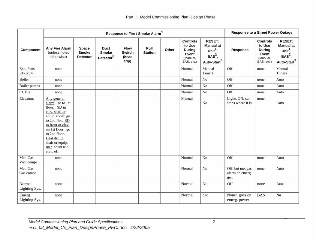
APPENDIX 2
--SAMPLE-- Fire and Emergency Power Response Matrix
Response to Fire / Smoke Alarm4 Response to a Street Power Outage
Component
Any Fire Alarm (unless noted
otherwise)
Space Smoke
Detector
Duct Smoke
Detector5
Flow Switch (head trip)
Pull Station
Other
Controls to Use During Event
(Manual, BAS, etc.)
RESET: Manual at
Unit1, BAS2,
Auto-Start3
Response
Controls to Use During Event
(Manual, BAS, etc.)
RESET: Manual at
Unit1, BAS2,
Auto-Start3
Roof Top Units Start / Stop
Shutdown Off--nocontrol.
Auto, but smoke dprs must be open
Shutdown none Auto, butsmoke dprs must be open
Dampers
Go to normal: OA is closed RA is open
EA is closed
na No Go to Normal none Auto
Terminal Units
Dampers: 100% open
Valves: no change
na No Dampers: stopwhere they are Valves: open
none Auto
Split FCU-2; ACU-1
none Normal(manual)
na None (go on emergency power)
Normal (manual)
Na
BAS
Receive and log an alarm
Normal na None (goes onown battery backup)
Off Na
Exh. Fans EF-1a,b, 2, 3
Off with RTU’s Override in BAS
No Off none Auto withRTU
Model Commissioning Plan and Guide Specifications 1 PECI 02_Model_Cx_Plan_DesignPhase_PECI.doc, 4/22/2005
Part II. Model Commissioning Plan−Design Phase
Response to Fire / Smoke Alarm4 Response to a Street Power Outage
Component
Any Fire Alarm (unless noted
otherwise)
Space Smoke
Detector
Duct Smoke
Detector5
Flow Switch (head trip)
Pull Station
Other
Controls to Use During Event
(Manual, BAS, etc.)
RESET: Manual at
Unit1, BAS2,
Auto-Start3
Response
Controls to Use During Event
(Manual, BAS, etc.)
RESET: Manual at
Unit1, BAS2,
Auto-Start3
Exh. Fans EF-1c; 4
none Normal ManualTimers
Off none ManualTimers
Boiler none Normal No Off none Auto
Boiler pumps none Normal No Off none Auto
CUH’s none Normal No Off none Auto
Elevators
Any general alarm: go to 1st floor. SD in elev. shaft or equip. room: go to 2nd flor. SD in front of elev. on 1st floor: go to 2nd floor. Heat det. in shaft or equip. rm.: shunt trip elev. off.
Manual No
Lights ON; car stops where it is
noneAuto
Med-Gas Vac. compr
none Normal No Off none Auto
Med-Gas Gas compr
none Normal No Off, but medgasalarm on emerg. gen
none Auto
Normal Lighting Sys.
none Normal No Off none Auto
Emerg. Lighting Sys.
none Normal nao None: goes onemerg. power
BAS Na
Model Commissioning Plan and Guide Specifications 2 PECI 02_Model_Cx_Plan_DesignPhase_PECI.doc, 4/22/2005

Part II. Model Commissioning Plan−Design Phase
Response to Fire / Smoke Alarm4 Response to a Street Power Outage
Component
Any Fire Alarm (unless noted
otherwise)
Space Smoke
Detector
Duct Smoke
Detector5
Flow Switch (head trip)
Pull Station
Other
Controls to Use During Event
(Manual, BAS, etc.)
RESET: Manual at
Unit1, BAS2,
Auto-Start3
Response
Controls to Use During Event
(Manual, BAS, etc.)
RESET: Manual at
Unit1, BAS2,
Auto-Start3
Data Management
none Normal na None: goes onemerg. power+UPS
Normal Na
Paging System
none Normal No Off none Auto
Security System
Operates per normal,
sending alarms
Normal na None: goes onemerg. power + on battery backup
Normal Na
Fire/Smoke Dampers
All close auto-resetif fusible link didn’t release
na None: slowly leak down and close
Normal Na
Fire Doors
All close, except OH doors at pharmacy, unless 1 of 3 adjacent clg. SD alarms
ua manreset
lly na None: goes on emerg. power + on battery backup
na Na
Emerg. Gen. & UPS
none na na Goes on-line &alarms to Security
Normal Na
Emerg. Pwr. Circuits
none na na None: go onemerg. power
Normal Na
Fire Alarm System Functions
normal operation
na na None: goes onemerg. power + on battery BU
Normal Na
Communica-tions to BAS
alarm sent to BAS from FAP
na na None
na Na
Model Commissioning Plan and Guide Specifications 3 PECI 02_Model_Cx_Plan_DesignPhase_PECI.doc, 4/22/2005

Model ComPECI
Part II. Model Commissioning Plan−Design Phase
missioning Plan and Guide Specifications 4 02_Model_Cx_Plan_DesignPhase_PECI.doc, 4/22/2005
Response to Fire / Smoke Alarm4 Response to a Street Power Outage
Component
Any Fire Alarm (unless noted
otherwise)
Space Smoke
Detector
Duct Smoke
Detector5
Flow Switch (head trip)
Pull Station
Other
Controls to Use During Event
(Manual, BAS, etc.)
RESET: Manual at
Unit1, BAS2,
Auto-Start3
Response
Controls to Use During Event
(Manual, BAS, etc.)
RESET: Manual at
Unit1, BAS2,
Auto-Start3
Communication to Outside Owner’s Site
gets fire and trouble
message via Sec. Co.
na na Gets messagevia Security Co.
na Na
Owner’s Securi
gets fire and trouble
message via in-bldg Security Co’s dialer
na na Gets messagevia in-bldg Security Co. dialer, due to UPS starting`
na Na
Fire Dept. fire alarm via Sec. Co
na na none na Na
1Manual reset required at RTU and RTU BAS field panel in order to restart after power is restored or fire alarm released. 2May be restarted at building automation system workstation when fire alarm is released and power is restored. 3Will be automatically restarted when fire alarm is released and power is restored. 4This does not include trouble alarms or release of fusible links in fire dampers, or heat detection and smoke detector in elevator shaft or equipment rooms. A smoke detector trip in the elevator shaft or equipment room causes elevator to go to 2nd floor. 5 A duct detector trip will cause a general alarm and will shut down all RTU’s. Only RTU associated with tripped detector requires manual reset at the RTU panel. On a normal general alarm, all RTU’s are automatically reset upon resetting the fire alarm panel.

Part II. Model Commissioning Plan−Design Phase
Model Commissioning Plan and Guide Specifications 1 PECI 02_Model_Cx_Plan_DesignPhase_PECI.doc, 4/22/2005
Fire Alarm Trouble Alarm
Fire Alarm Panel
Building Automation System
Security System Dialer(In Bldg.)
Remote Monitoring Site (Security Co.)
Fire DepartmentOwner's Remote Site
Close Fire / Smoke Dampers
Shut Off Rooftop Units (RTU-1,2,3;4) and Exhaust Fans
(EF-1a, 1b, 2; 3)
* Release all fire doors (except overhead doors at pharmacy, unless an adjacent clg SD alarms)* Audible and Visual Alarms* Elevators return to 1st flr, unless initiating alarm was at a 1st flr elev, then that elev. returns to 2nd flr.
Fire
Fire or Trouble
Fire or Trouble Fire
--Sample--Fire Alarm Sequence Flow Chart
11/21/96
Fire
Fire Alarm includes any initiating event (pull station, space or duct smoke detector, heat dector or sprinkler flow). It does not include fire damper fusible link release of a fire damper. Heat detector in elevator equip. room or shaft has 30 sec.delay to allow recall to floors, then power to elevator is shunt-tripped off.Trouble Alarm includes any of the troubles listed in Appendix M of the FAP O&M.
[fire_flo.sg]