part i the schedule section c performance work statement ... · two high-activity feed streams for...
TRANSCRIPT

Savannah River Site Liquid Waste Services Section C Draft Solicitation No. DE-SOL-0008913
C-1
PART I – THE SCHEDULE
SECTION C – PERFORMANCE WORK STATEMENT
TABLE OF CONTENTS
C.0 Savannah River Site Liquid Waste Contract Overview and Objectives .................................... 3
C.0.1 Background ..................................................................................................................................... 3
C.0.2 Contract Purpose and Objectives ................................................................................................ 3
C.0.3 Description of Performance Requirements ................................................................................ 5
C.0.4 Transition ......................................................................................................................................... 7
C.0.4.1 Key Scope and Requirements .................................................................................................. 7
C.1 Liquid Waste Operations (WBS: 01) ............................................................................................. 10
C.1.1 Tank Farms (WBS: 01.01) .......................................................................................................... 11
C.1.1.1 Actinide Removal Process/Modular Caustic Side Solvent Extraction Unit (WBS: 01.01.01) . 11
C.1.1.2 Tank Farm Operations (WBS: 01.01.02) ................................................................................. 12
C.1.2 Waste Vitrification (WBS: 01.02) ................................................................................................ 18
C.1.2.1 Defense Waste Processing Facility (WBS: 01.02.01) .............................................................. 18
C.1.2.2 Glass Waste Storage Buildings (WBS: 01.02.02) .................................................................... 20
C.1.3 Low Activity Waste Disposal (WBS: 01.03) .............................................................................. 21
C.1.3.1 Saltstone Production Facility (WBS: 01.03.01) ...................................................................... 21
C.1.3.2 Saltstone Disposal Facility (WBS: 01.03.02) ........................................................................... 22
C.1.4 Salt Waste Processing Facility Operations (post transition) (WBS: 01.04) ......................... 22
C.2 Liquid Waste Operations Support (WBS: 02) .............................................................................. 25
C.2.1 Saltstone Disposal Unit Construction (WBS: 02.01) ............................................................... 25
C.2.2 Salt Waste Processing Facility Integration (WBS: 02.02) ...................................................... 26
C.2.3 Salt Waste Processing Facility Transition (WBS: 02.03) ....................................................... 27
C.2.4 Tank Closures (WBS: 02.04) ...................................................................................................... 28
C.2.4.1 Heel Removal and Residual Sampling (WBS: 02.04.01) ......................................................... 28
C.2.4.2 Tank Isolation (WBS: 02.04.02) .............................................................................................. 29
C.2.4.3 Tank Grouting (WBS: 02.04.03).............................................................................................. 30
C.2.5 Safety Basis Upgrade Implementation (WBS: 02.05) ............................................................. 30
C.2.6 System Optimization (WBS: 02.06) ........................................................................................... 31
C.2.6.1 Next Generation Solvent Deployment (WBS: 02.06.01) ........................................................ 32
C.2.6.2 At-Tank Cesium Removal (WBS: 02.06.02) ............................................................................ 32
C.2.6.3 Dry Feed Modifications (WBS: 02.06.03) ............................................................................... 33
C.2.6.4 Melter Fabrication (WBS: 02.06.04) ...................................................................................... 34
C.2.6.5 DWPF Operational Improvements (WBS: 02.06.05) .............................................................. 34

Savannah River Site Liquid Waste Services Section C Draft Solicitation No. DE-SOL-0008913
C-2
C.2.6.6 Tank 48 Recovery (WBS: 02.06.06) ........................................................................................ 34
C.2.6.7 Technology Development and Deployment (WBS: 02.06.07) ............................................... 35
C.2.7 Additional Glass Waste Storage Capability (WBS: 02.07) ..................................................... 35
C.3 Liquid Waste Program Support (WBS: 03) .................................................................................. 37
C.3.1 Management of Standards/Requirements Identification Document Functional Areas
(WBS: 03.01)............................................................................................................................................. 37
C.3.1.1 Integrated Safety Management System ................................................................................ 38
C.3.1.2 Safety Culture and Safety Conscious Work Environment ...................................................... 39
C.3.1.3 Department of Energy/National Nuclear Security Administration Radiological Emergency
Response Asset Support ..................................................................................................................... 39
C.3.2 Management and Administrative Services (WBS: 03.02) ...................................................... 39
C.3.3 Government Furnished Services and Items (WBS: 03.03) .................................................... 40
C.3.3.1 Functional Service Agreements .............................................................................................. 41
C.3.4 Legacy Benefits (Pension and Post-Retirement Benefits) (WBS: 03.04) ............................ 42
C.4 Indefinite Delivery/Indefinite Quantity Work ................................................................................. 43
Attachment 1 – Liquid Waste Process Diagram .................................................................................. 44
Attachment 2 – Liquid Waste Facilities ................................................................................................. 45
Attachment 3 – Schematic of the ARP/MCU Process ........................................................................ 46
Attachment 4 – SRS Tank Closure Regulatory Roadmap ................................................................. 47
Savannah River Site Liquid Waste Services Section C Draft Solicitation No. DE-SOL-0008913
C-3
C.0 Savannah River Site Liquid Waste Contract Overview and Objectives
C.0.1 Background
The Department of Energy (DOE) Savannah River Site (SRS) is located in western South
Carolina, covering 310 square miles in Aiken, Allendale and Barnwell counties. SRS was
constructed during the early 1950s to produce basic materials used in fabrication of nuclear
weapons, primarily tritium and plutonium-239, in support of our nation's defense programs.
The SRS cleanup strategy is to eliminate or minimize nuclear materials, spent nuclear fuel
(SNF), and waste through safe stabilization, treatment, and/or disposition; reduce costs of
continuing operations and surveillance and maintenance; and decommissioning facilities, as
well as remediate surface water, groundwater and contaminated soils consistent with regulatory
agreements and permits. The Department's completion strategy provides a comprehensive
risk-based methodology to the legacy cleanup project, such as dispositioning radioactive liquid
waste (LW) through vitrification of high activity waste constituents at the site's Defense Waste
Processing Facility (DWPF), using existing SRS facilities to receive, store, and disposition
aluminum-clad SNF, and decommissioning all facilities not required for continuing missions.
Major activities at SRS include radioactive liquid waste stabilization and disposition projects to
safely and effectively store, treat, stabilize, and dispose of approximately 37 million gallons of
legacy radioactive waste currently stored in more than 40 underground storage tanks.
C.0.2 Contract Purpose and Objectives
The purpose of this Contract is to achieve measureable progress toward completion of the DOE
Environmental Management (EM) mission at SRS to process and stabilize high level waste into
borosilicate glass and low activity waste into cementitious material in accordance with the
requirements of a regulatory framework that includes: 1) Section 3116(a) of the Ronald W.
Reagan National Defense Authorization Act (NDAA) for Fiscal Year 2005 ; 2) the Federal
Facilities Agreement (FFA); 3) permits and requirements issued by the South Carolina
Department of Health and Environmental Control (SCDHEC); and 4) applicable DOE Orders.
The liquid waste system is divided by function into four operational sub-systems: (1) waste
storage, retrieval, sludge pretreatment, and closure of underground LW storage tanks/systems
in the F-Area and H-Area Tank Farms (Tank Farms1); (2) salt waste treatment in processing
1 The official facility nomenclature for the “Tank Farms” is the Concentration, Storage, and Transfer
Facilities (CSTF). This document uses various terms including Tank Farms, F-Tank Farm, H-Tank Farm, etc… to refer to the CSTF.

Savannah River Site Liquid Waste Services Section C Draft Solicitation No. DE-SOL-0008913
C-4
facilities; (3) high activity waste treatment by vitrification in the DWPF with onsite glass storage
until a disposal facility is available; and (4) stabilization of low level liquid waste in the Saltstone
Production Facility (SPF) with disposition as grout in Saltstone disposal units. The Contract
scope includes the future operation and maintenance of the Salt Waste Processing Facility
(SWPF), currently being commissioned under another contract that also includes an initial
operational period of one year.
EM mission completion at SRS involves the safe stabilization, treatment, and disposal of
radioactive liquid wastes presently stored in more than 40 underground radioactive waste
storage tanks as well as future radioactive liquid waste resulting from planned nuclear materials
stabilization activities; operational closure of underground waste storage tanks; and deactivation
of major facilities and equipment that comprise the radioactive liquid waste system. An
overview diagram of the liquid waste system process is included in Attachment 1. An aerial
view of the liquid waste facilities is illustrated in Attachment 2.
The major objectives of this Contract during the base and option period of performance include
the following:
- Safely operate and optimize the liquid waste system. Identify, develop, and implement
improved supplemental, or replacement processes, approaches, and technologies for
waste treatment, waste removal, tank closure, and waste disposal that reduce program
lifecycle costs, accelerate radioactive liquid waste disposition schedules, or otherwise
optimize system performance.
- Support timely completion, startup and initial operation of the SWPF by fulfilling all
interface responsibilities, e.g. waste transfer infrastructure, delivery of qualified salt
batches from waste removal operations as feed for SWPF, and receipt from SWPF of (a)
two high-activity feed streams for processing at DWPF and (b) a low-activity feed stream
for processing and disposal at the Saltstone Facility.
- After the transfer of operational responsibility, operate and maintain the SWPF to
process salt waste at SWPF to yield two high-activity salt streams which meet waste
feed acceptance criteria for processing at DWPF and a low-activity salt stream which
meets waste feed acceptance criteria for processing and disposal at the Saltstone
Facility.
- Operate Tank Farms to maintain a constant source of waste feed to Liquid Waste
processing facilities in keeping with each facility’s capability to receive and process
waste. This will include planning and staging to support a continued and uninterrupted
source of waste feed to Liquid Waste processing facilities to include:
o Receive liquid radioactive waste from H Canyon nuclear material stabilization
activities.
Savannah River Site Liquid Waste Services Section C Draft Solicitation No. DE-SOL-0008913
C-5
o Deliver salt waste feed, fully conforming with the SWPF salt feed waste
acceptance criteria, to SWPF for processing.
o Operate and maintain the Actinide Removal Process (ARP) and the Modular
Caustic Side Solvent Extraction Unit (MCU) pending the start of SWPF
operations to process salt waste from waste removal operations into two high-
activity feed streams for processing at DWPF and a low-activity feed stream for
processing and disposal at the Saltstone Facility.
- Operate and maintain the DWPF to produce DWPF canisters at optimal sludge and salt
waste loadings.
- Operate and maintain Glass Waste Storage Building (GWSB) #1 and #2 to store the
vitrified waste canisters produced by DWPF.
- Operate and maintain the Saltstone Facility consisting of the SPF and the Saltstone
Disposal Facility (SDF) to process and dispose of low-level waste.
- Construct SDUs to support the continued and uninterrupted disposal of low-level waste
at the SDF.
- Operationally close liquid radioactive waste storage tanks and associated facilities in
support of the FFA.
- Operate and maintain the Effluent Treatment Facility (ETF) (also known as Effluent
Treatment Project) to process aqueous waste streams from Liquid Waste system
operations and from other site operations into a form suitable for (a) release to a
permitted outfall or (b) processing and disposal at the Saltstone Facility.
- Maintain an interactive program/system planning process for Liquid Waste program
milestones and execution schedules including comprehensive salt and sludge batch
planning.
C.0.3 Description of Performance Requirements
This Contract reflects application of performance-based contracting approaches and techniques
emphasizing measurable results/outcomes. The Contractor has responsibility for total
performance under the Contract, including determining specific methods and approaches for
accomplishing work.
All activities at SRS are managed by DOE EM site leadership. The Contractor shall be required
to coordinate some of its activities by participating in a government-managed site integration
process (including Government Furnished Services & Items (GFS&I)) to the extent necessary to
ensure safe conduct of all site activities and completion of Contract requirements.
The Contractor has responsibility for managing, integrating, and executing work described in
this Performance Work Statement (PWS). The Contractor shall assure that all activities are

Savannah River Site Liquid Waste Services Section C Draft Solicitation No. DE-SOL-0008913
C-6
conducted in compliance with applicable environmental laws and regulations and within the
parameters set forth in the following National Environmental Policy Act documents and
associated Records of Decision.
- DWPF Final Environmental Impact Statement (FEIS) (DOE/EIS-0082)
- Supplement Analysis Salt Processing Alternatives (DOE/EIS-0082-SA-01)
- Final Waste Management Programmatic Environmental Impact Statement (PEIS)
(DOE/EIS-0200-F)
- SRS Waste Management Final Environmental Impact Statement (EIS) (DOE/EIS-0217)
- Interim Management of Nuclear Materials EIS (DOE/EIS-0220)
- SRS High-Level Waste Tank Closure Final EIS (DOE/EIS-0303)
- Environmental Assessment (EA) for the Closure of the HLW Tanks in F- and H-Areas at
SRS (DOE/EA-1164)
- SRS Salt Processing Alternatives Final Supplemental Environmental Impact Statement
(SEIS) (DOE/EIS-0082-S2)
During conduct of authorized work scope, the Contractor shall also comply with applicable
provisions of all other Comprehensive Environmental Response, Compensation and Liability Act
of 1980 decision documents in effect for the site.
The PWS scope contains both operational and capital asset acquisition activities which shall be
identified as subprojects. The Contract scope shall be managed using a formal
decision/approval process consistent with program and project management principles. The
Contractor shall be responsible for integration and management of Contract and subproject
scope. Scope performance must clearly link funding to cost reporting. A Work Breakdown
Structure (WBS) that breaks down the work scope to levels below the WBS provided in this
document as Section J, Attachment J-3 shall be developed to provide for efficient program and
cost management. All work is subject to the development and implementation of an Earned
Value Management System (EVMS). Since the Contract scope shall be managed as a project,
the Contractor shall be responsible for developing a cost performance measurement system, in
addition to an EVMS, at the Contract and subproject levels. The Contractor’s participation in the
DOE Project Assessment and Reporting System is required for capital asset project
performance reporting.
The Contractor must comply with DOE and site requirements. Requirements that have been
incorporated into the Contract remain in effect throughout the term of the Contract unless, and
until, the Contract or regulatory commitment is modified to either eliminate requirements that are
no longer applicable or substitute a new set of requirements.
This PWS is structured such that required actions are shown directly under each section header
and WBS element. Subheadings entitled “Supplemental Information” provide varying levels of
detailed information on the work scope that bidders may find useful in developing proposals.
Supplemental information shall not be construed as providing work scope requirements or
defining the only acceptable approach to operating a facility, system, or process.

Savannah River Site Liquid Waste Services Section C Draft Solicitation No. DE-SOL-0008913
C-7
Listed below are the performance requirement metrics for this contract during the base period of
performance and during the option period.
Table 1: Contract Performance Requirements
Performance Metric Salt Waste
Processed
(gallons)
Bulk Waste
Removal
(tanks)
Tank
Closures
(tanks)
Base Contract Period 45,000,000 9 6
Option Period 27,000,000 2 3
Total Contract Term 72,000,000 11 9
C.0.4 Transition
The Contractor shall transition all on-going work scope from the incumbent including existing
Service Level Agreements (SLAs); novate any subcontract work from the incumbent to continue
under an existing subcontract; and complete workforce transition in accordance with the
requirements of the Contract. All Government-owned real and personal property currently
accountable to the incumbent contractor for contract performance will be provided to the
Contractor. During the contract transition period an inventory record of such property in the
DOE Facilities Information Management System (FIMS) and incumbent contractor’s personal
property databases will be provided to the Contractor.
The Contractor shall establish the necessary logistical support (office space, computers,
telephone, etc.) to execute transition and shall ensure all necessary personnel, including key
personnel for the Contractor, are on-site during the transition period.
At the end of the transition phase, the Contractor shall notify the Contracting Officer (CO) in
writing that it is ready to assume full responsibility for the scope of the Contract.
C.0.4.1 Key Scope and Requirements
Sections C.0.4.1.1 through C.0.4.1.8 below identify major elements necessary for transition of
the Contract.
C.0.4.1.1 Transition Plan
The Contractor shall submit a Transition Plan that provides a description of all necessary
transition activities, involved organizations, and transition schedule. The objectives of the
Transition Plan are to prepare for implementation of the Contract and minimize the impacts on
continuity of operations. The Contractor is responsible for performing due diligence to ensure
that all transition activities are identified and completed during the Transition Period. The
Transition Plan shall be submitted within 14 calendar days after issuance of the Notice to
Proceed (NTP).

Savannah River Site Liquid Waste Services Section C Draft Solicitation No. DE-SOL-0008913
C-8
C.0.4.1.2 Service Level Agreements and Inter-Contractor Ordering Agreements
The Contractor shall develop the Service Level Agreements and Inter-Contractor Ordering
Agreements that are necessary to support transition and Contract performance, and shall be
responsible for the costs incurred under these agreements. SLAs are negotiated between the
LW Contractor and other SRS contractors.
C.0.4.1.3 Performance Management Baseline
The Contractor shall submit a Performance Management Baseline (PMB), including an EVMS
description, for the Contract Base Period of Performance that details the work activities to be
performed. The Contractor shall develop the initial PMB based on the Department of Energy
Savannah River (DOE-SR) WBS (Section J, Attachment J-3).
C.0.4.1.4 Status Reports-Transition Activities
The Contractor shall provide a weekly status report of transition activities to DOE. The
Contractor shall establish routine status meetings with DOE and affected contractors to review
transition activities and issues.
C.0.4.1.5 Government-Owned Property
The Contractor shall conduct a joint reconciliation of the Government property inventory with the
incumbent contractor. The incumbent contractor will provide an inventory record of all real and
personal property for which they are accountable. The incumbent contractor and the Contractor
shall perform a joint wall-to-wall physical inventory during the Transition Period, after which the
Contractor shall report any discrepancies to the CO and the DOE Property Manager. This
information shall be used to provide a baseline for this Contract as well as information to close
out the incumbent contract.
C.0.4.1.6 DOE Safeguards and Security Survey
During the Contract transition period and prior to assuming control and responsibility for
Safeguards and Security (SAS) responsibilities, the Contractor shall be subject to a DOE SAS
initial survey conducted in accordance with U.S. DOE Order 470-4B, Safeguards and Security
Program. The results of the survey shall be documented and shall form the basis for DOE
authorization to assume SAS responsibilities, in particular, responsibility for Special Nuclear
Material. Upon DOE authorization, the Contractor shall assume responsibility for all applicable
SAS resources, materials, facilities, documents, and equipment.
C.0.4.1.7 Identification of Material Differences
During the Transition Period, the Contractor shall identify any material differences in the
systems, facilities, waste sites, property and services described in this PWS and actual
conditions at the end of the transition period. The Contractor shall prepare and submit a
Statement of Material Differences within 45 days of the NTP. If the Material Differences require

Savannah River Site Liquid Waste Services Section C Draft Solicitation No. DE-SOL-0008913
C-9
revisions to the Contract, the Contractor shall submit a change proposal to reconcile the
material differences with the Contract by the end of the contract transition period.
C.0.4.1.8 Stakeholder Engagement
During the Transition Period, the Contractor shall brief workers, Federal staff and stakeholders
on the Contractor’s approach and commitments for accomplishing the PWS.
Within 72 hours following a NTP, the Contractor shall release on its own website a brief
Executive Summary of its offer including the following elements:
Name of Contractor including the identification of any Teaming Partners and Major
Subcontractors and a description of the experience that each brings to the project.
Summary/Description of Contractor’s Technical Approach
Organizational Structure and Identification of Key Personnel
Commitments to the Community for the Period of Performance
Total Contract Value Commitment to Small Business Subcontracting
Contractor Performance Commitments
Brief overview of Contractor’s Work on Similar Projects
The purpose of this Executive Summary is to provide immediate release of relevant information
to stakeholders and the public at large.

Savannah River Site Liquid Waste Services Section C Draft Solicitation No. DE-SOL-0008913
C-10
C.1 Liquid Waste Operations (WBS: 01)
The mission of LW Operations is to receive, store, treat, and dispose of radioactive liquid waste.
The LW Operations are highly integrated involving safely storing liquid radioactive waste in
underground storage tanks; removing, treating, and dispositioning the low activity waste fraction
in concrete SDUs; vitrifying the higher activity waste at DWPF; and storing the vitrified waste in
stainless steel canisters until permanent disposition.
The Contractor shall initially adopt the incumbent Contractor’s programs and implementing
procedures (e.g., Documented Safety Analysis (DSA), Technical Safety Requirements (TSRs),
nuclear safety operating procedures, Performance Assessments, etc.) to facilitate continuity of
operations and accomplishment of work. To ensure compliance with Contract requirements,
current regulatory requirements, DOE directives and Contractor organizational roles and
responsibilities, the Contractor is responsible to perform its own compliance verification of these
programs and the implementing procedures. The Contractor, with DOE acceptance as
appropriate, shall revise programs and implementing procedures it deems necessary to
accommodate its technical approach, while maintaining compliance.
The Contractor shall maintain compliance with site-wide Manuals governing operations and
maintenance requirements. These activities include routine operations, predictive, preventive
and corrective maintenance, and infrastructure activities needed to support LW facilities and any
facility improvements including general plant projects, major modifications, temporary
modifications, and line item projects needed to sustain facility operations. Facilities shall be
maintained in a condition such that the facilities can be operated as designed beyond the end of
the contract period of performance.
DOE maintains a comprehensive Master Infrastructure List of critical facility and infrastructure
needs. Infrastructure for the purpose of this work scope includes all facility support structures;
operational equipment; fire protection; electrical systems; plumbing; heating, ventilation and air
conditioning equipment; superstructures; interior and exterior enclosures; roofing; foundations;
basement construction; conveying systems; stairs; and furnishings. The areas of consideration
include the Tank Farms and associated systems, structures and components, S-Area, Z-Area,
ETF, and SWPF in J-Area, once the SWPF is transitioned to the Contractor. It also includes the
office trailers and other supporting facilities in areas B, E, G and T-Areas (see Attachment J-12,
Appendix A - LW facilities12-8-2015). The Contractor shall provide to DOE updated input by the
end of each fiscal year, including a prioritized list of maintenance activities for these areas that
were accomplished during the fiscal year, maintenance activities that are scheduled to be
performed, and newly identified maintenance activities. The maintenance activities shall be
prioritized and risks associated with non-performance of the maintenance activities shall be
identified and described with respect to safety and continued operations.
Supplemental information included in Section C is provided to aid in understanding the
requirements and does not add any additional requirements.
Savannah River Site Liquid Waste Services Section C Draft Solicitation No. DE-SOL-0008913
C-11
C.1.1 Tank Farms (WBS: 01.01)
Tank Farms operation includes multiple facilities and processes, including the ARP/MCU, waste
tank system transfers, evaporator operations, space management, salt and sludge feed batch
retrieval and preparation for transfer to other LW facilities, waste disposition, and, ultimately,
tank closure.
C.1.1.1 Actinide Removal Process/Modular Caustic Side Solvent Extraction Unit (WBS:
01.01.01)
The Contractor shall manage and optimize interim salt processing and disposition of radioactive
salt waste using the integrated ARP/MCU system, strategically reducing inventory and
recovering tank space supporting Canyon operations. The Contractor shall deliver a low-activity
clarified salt solution waste stream (i.e., treated to remove actinides, strontium and cesium) as
feed to the SPF for processing and to derive a high-activity concentrated radioactive cesium
stream and an actinide/strontium salt stream as feed for processing at the DWPF.
Following shutdown to allow for SWPF tie-in to the liquid waste system, the Contractor shall
maintain the ARP/MCU processes and facilities in a lay-up status with waste having been
flushed from all vessels, transfer lines, coalescers, contactors, instrument lines, ventilation
system reheaters and condensers, cells, sumps, and all locations exposed to radioactive or
chemical waste, to the maximum extent practicable until such time as SWPF has transitioned to
the Contractor for continued operation. Layup includes separation of all transfer lines and
capping/blanking the lines. Ventilation system filters will continue to be maintained to ensure
any residual contamination may not be released from the facilities.
Supplemental Information
Attachment 3 provides a schematic diagram of the ARP/MCU process. Lower activity salt waste
is currently processed through ARP/MCU. The ARP decontaminates salt solution via
adsorption of strontium-90 (Sr90), actinide radionuclides, and entrained sludge solids in the salt
solution onto Mono-Sodium Titanate (MST) followed by filtration or settling. The actinides,
Sr90, and MST laden sludge waste stream are transferred to DWPF for vitrification and the
remaining clarified salt solution is transferred to the MCU process. The MCU process extracts
cesium-137 (Cs-137) from the clarified salt solution using Caustic Side Solvent Extraction
(CSSX) chemistry. The low Cs137/low actinide Decontaminated Salt Solution (DSS) is
subsequently transferred to Tank 50 for feed to the SPF, and the Strip Effluent (SE) solution of
cesium nitrate from the CSSX process is transferred to the DWPF for vitrification. In
combination with evaporation, the operation of ARP/MCU reclaims valuable space in the F-Area
and H-Area waste storage tanks and supports continued DWPF operations. ARP/MCU
treatment will be replaced in the future by the SWPF, which is under construction. SWPF will
process significantly larger amounts of salt waste that are also higher in radioactivity.
ARP/MCU facilities outputs ensure the total Interim Salt Treatment curies emplaced in SPF are
within the amount identified in Savannah River Site – Liquid Waste Disposition Processing

Savannah River Site Liquid Waste Services Section C Draft Solicitation No. DE-SOL-0008913
C-12
Strategy (SRS LW Strategy), as amended by letter from the SCDHEC to DOE-SR and Section
3116(a) of the NDAA FY2005.
The ARP/MCU is currently projected to operate at a rate of 4-8 gallons per minute (gpm) until
the facility is shut down for SWPF tie-ins approximately four weeks prior to the start of SWPF
operations. In the event SWPF start-up is initially unsuccessful, ARP/MCU will continue to
operate until such time as SWPF is authorized to begin operations. Nominally ARP/MCU
produces:
- For each gallon processed, approximately 1.2 gallons of DSS for SPF
- For each gallon processed, approximately 0.08 gallon of SE for DWPF
- For each gallon processed, approximately 0.02 gallon of MST solids/sludge for
DWPF
Note: actual operating experience in ARP/MCU since beginning Next Generation Solvent (NGS)
processing may vary slightly from these assumptions as data is collected and analyzed.
Actions taken since startup of ARP/MCU have demonstrated an increased processing rate from
the original design of 1 million gallons per year to approximately 1.5 million gallons per year.
Enhancements and improvements include chemistry adjustments at Tank 49, reduced cycle
times, and redesign and replacement of the secondary filter at facility 512S.
Efforts continue to improve equipment reliability, reducing unexpected downtime to improve
overall attainment. In addition to equipment and processing upgrades, alternative system
planning is being done to more efficiently qualify subsequent salt batches to reduce downtime
between batches.
Operation of ARP/MCU with NGS has resulted in more efficient removal of cesium from the
treated salt solution than the original solvent formula. This increased cesium removal efficiency
(decontamination factor or DF) allows ARP/MCU to produce a DSS stream with a residual
cesium concentration much less than previously achieved.
C.1.1.2 Tank Farm Operations (WBS: 01.01.02)
The Contractor shall operate and optimize the Tank Farms to receive, concentrate, and store
liquid radioactive wastes in support of ongoing site activities and ensure the continued
operability and structural integrity of the liquid radioactive waste tanks and ancillary structures.
The Contractor shall be responsible for effective Tank Space Management, Salt Feed
Preparation, Sludge Feed Preparation, bulk waste retrieval, and management of the ETF. The
Contractor shall maintain a comprehensive tank inspection program to actively monitor all tanks
for new leaks, and the Contractor shall mitigate any newly discovered leak sites. Mercury
monitoring/sampling and chemical analysis throughout the LW systems will continue to be
performed. Mercury shall be removed from the evaporator mercury removal columns as
specified in the TSRs.

Savannah River Site Liquid Waste Services Section C Draft Solicitation No. DE-SOL-0008913
C-13
Supplemental Information
The liquid waste contained in the underground storage tanks is in the form of saltcake, salt
supernate, or sludge. The functions of the underground storage tanks are:
- Receipt and storage of radioactive liquid waste and by-products generated by operation
of the chemical separations processing and research facilities.
- Prevention of potentially harmful exposure from radiation to site worker and members of
the public.
- Prevention of potentially harmful quantities of radionuclides and chemicals from
escaping to the environment.
- Maintaining safe storage of the liquid radioactive waste.
- Preparing batches of liquid radioactive waste for treatment into a more stable form
(solidification) for final disposition.
The F-Area Tank Farm (FTF) is a 22 acre site containing eight Type I, two Type III, eight Type
IIIA, and four Type IV storage tanks. Six tanks in FTF have been operationally closed. In
addition, FTF also includes supporting ancillary structures such as two evaporator systems,
transfer pipelines, diversion boxes, a concentrate transfer system, a catch tank, and three pump
pits. The H-Area Tank Farm (HTF) is a 45 acre site containing four Type I, four Type II, four
Type III, thirteen Type IIIA, and four Type IV tanks. One tank in H-Tank Farm has been
operationally closed and a second tank will be closed in 2016. In addition, HTF includes
supporting ancillary structures such as three evaporators, eight diversion boxes, ten pump pits,
pump tanks, transfer valve boxes, and transfer piping. Also located in HTF is the ARP/MCU
processing system. The twenty-four Type I, II, and IV tanks do not meet the secondary
containment standards in the SRS Federal Facility Agreement. Seven of these tanks have been
operationally closed and the eighth tank will be closed in 2016. Out of these sixteen tanks that
remain in service, eight tanks have leaked waste through the primary tank wall into their
respective secondary containment (i.e. annulus space). Waste retrieval operations in Type I
and II tanks that have leak sites may reactivate these leak sites or expose new leak sites.
C.1.1.2.1 Tank Space Management (WBS: 01.01.02.01)
The Contractor shall maintain usable working tank storage capacity (space) to support waste
retrieval and treatment operations (e.g., preparation of sludge and salt feed and receipt of waste
from DWPF, ETF, and H-Canyon). The Contractor shall implement effective supplemental
space management initiatives as necessary, including the operation of evaporator systems.
Supplemental Information
Since 1951, the Tank Farms have received over 160 Mgal of liquid waste, of which most have
been evaporated and/or treated, leaving approximately 36.2 Mgal in the storage tanks.
Available storage space is used for waste receipts, waste retrieval, and processing operations.
A contingency amount of 1.3 Mgal is not included as working space and is reserved for the
unlikely event of a full tank failure. Waste receipts and transfers are normal Tank Farm
Savannah River Site Liquid Waste Services Section C Draft Solicitation No. DE-SOL-0008913
C-14
activities as the Tank Farms receive new or “fresh” waste from the HCanyon stabilization
program, liquid waste from DWPF processing (typically referred to as “DWPF recycle”), wash
water from sludge washing, and very small amount of concentrate from ETF. The Tank Farms
also make routine transfers to and from waste tanks and evaporators. Two evaporator systems
are currently operating, the 2H and 3H systems, supporting space management by volume
reduction of 2 – 3 million gallons per year of liquids produced by sludge batch washing and
DWPF recycle receipts..
Space in Type III/IIIA tanks is used for storage and treatment operations. Tank space is
recovered through evaporator operations, DWPF vitrification, and ARP/MCU Treatment. This
valuable space has been used to: (1) retrieve waste from and clean older style (Type I, II, and
IV) tanks; (2) prepare, qualify, and treat sludge waste for disposal; (3) prepare, qualify, treat,
and dispose salt waste; and (4) support nuclear materials stabilization and disposal through H-
Canyon. The four Type IV tanks in HTF support immobilization and disposition of high-level
waste. The Tank Farm space management strategy in the Liquid Waste System Plan is based
on projections of DWPF canister production rates, salt waste processing rates, influent stream
volumes, Tank Farm evaporator performance, and space gain initiative implementation.
Tank Farm Operations support:
- Salt processing – salt batching, qualification and disposition
- Sludge processing – sludge batching qualification and disposition
- H-Canyon waste receipts
- Continued safe storage of radioactive liquid waste
- Defense in depth operational control
- Maintain contingency space for recovery in the event of full loss of containment of a tank
- Working space for evaporator operations
C.1.1.2.2 Salt Feed Preparation (WBS: 01.01.02.02)
The Contractor shall be responsible for operation and maintenance of equipment necessary to
dissolve, batch, and adjust salt waste from various tanks to serve as feed for ARP/MCU and
SWPF. Salt batches shall meet the WAC of the facility it will be transferred to. For each salt
batch prepared, the Contractor shall provide to DOE a Salt Batch Preparation/Qualification
Report.
Tank Farm feed preparation infrastructure modifications required to support SWPF processing
rates include:
- HTank Farm Blend tanks readiness for salt solution preparation
- Tank 49H readiness as SWPF feed tank
- Mixing capabilities
- Enhanced transfer capabilities
- Transfer routes provided to blend/feed tank(s)

Savannah River Site Liquid Waste Services Section C Draft Solicitation No. DE-SOL-0008913
C-15
For the purposes of measuring performance against contractual commitments, “salt waste
processed” is defined as the volume of liquid salt waste that meets the waste acceptance
criteria of the facility receiving the waste for processing. This volume will be measured as it is
transferred from the salt waste feed tank, currently Tank 49H.
Supplemental Information
Salt feed preparation includes development of salt batches from various waste tanks for feed to
salt treatment processes including ARP/MCU and SWPF. Salt Feed Preparation for each batch
currently requires three months for sampling, analysis, and transfer into the batch feed tank.
SWPF is planned to process the majority of this salt solution waste. Salt preparation capability
is currently limited by the number of blend tanks available to prepare salt batches. Currently, a
single tank is capable of preparing 3 to 4 Mgal/yr. Only two blend tanks are expected to be
available upon SWPF startup; however a third tank will be needed to enable the Tank Farms to
feed SWPF at 9 Mgal/yr. The planned salt batches are identified in the approved Liquid Waste
System Plan.
Factors that impact salt feed preparation include:
- Blend Tank availability
- SE & MST processing in DWPF at optimum throughput rates
- DSS processing in SPF at optimum throughput rates and availability of SDUs
Future salt treatment technology demonstration of the at-tank cesium removal using the Ion
Exchange (IX) process is under investigation. Refer to Section C.2.6.2 for additional
information.
C.1.1.2.3 Sludge Feed Preparation (WBS: 01.01.02.03)
The Contractor shall be responsible for operation of equipment and conducting treatment
processes used to prepare sludge waste feed to sustain DWPF vitrification operations. The
Contractor shall effectively couple tank waste removal operations with sludge waste feed
preparation operations to provide sludge waste: 1) within compositional ranges that support
sludge waste blending and preparation into batches that meet DWPF prescribed feed
specifications; and 2) with sufficient volume to ensure the continuous availability of sludge waste
feed to DWPF. For each sludge batch prepared, the Contractor shall provide to DOE a Sludge
Batch Preparation/Qualification Report. The Contractor shall also model sludge waste feed
preparation activities and execute activities necessary to ensure that DWPF vitrification
operations can be sustained beyond the Contract period of performance.
Supplemental Information
The basic steps for sludge processing are: 1) Sludge removal from tanks; 2) Optional Low-
Temperature Aluminum Dissolution; 3) Blending and washing of sludge; and 4) Sludge feeding
to the DWPF. Currently a single tank (Tank 51) is the sole DWPF feed preparation tank (see
Figure 1).

Savannah River Site Liquid Waste Services Section C Draft Solicitation No. DE-SOL-0008913
C-16
Sludge preparation is paced by available canister storage, bulk waste retrieval, and by tank
storage space to prepare sludge batches. Sludge batch planning uses the estimated mass and
composition of sludge and known processing capabilities to optimize processing sequences.
The planned sludge batches are identified in the approved Liquid Waste System Plan.
Differences in sludge batch sequencing, total number canisters produced, and batch end dates
is an effort to balance the end of salt processing more closely with the end of sludge processing,
reducing the necessity for supplemental chemical additions. The projected canister pour rate is
balanced to be appropriate for salt processing support.
High-heat sludge generated from spent nuclear fuel processing in H-Canyon has resulted in
high amounts of aluminum solids as gibbsite or boehmite. Much of this aluminum can be
removed from the sludge by dissolution of the aluminum and subsequent removal by decanting
of the liquid phase. This reduces the number of canisters needed to disposition the sludge, due
to the lowered sludge solids mass and improved waste loading in the glass. Dissolution is
achieved by adding caustic, elevating temperature, mixing, and sufficient reaction time.
Sodium and other soluble salts (e.g., sulfates, nitrates, nitrites) in DWPF feed are reduced
through sludge washing. Sludge washing is performed by adding water to the sludge batch,
mixing with slurry pumps, securing the pumps to allow gravity settling of washed solids, and
decanting the sodium-rich supernate to an evaporator system for concentration. This cycle is
repeated until the desired molarity (typically 1.25 M Na) is reached. Some types of sludge settle
slowly, extending wash cycles. Sludge settling and washing typically constitutes ~75% of batch
preparation time. The total number of washes performed and volume of wash water used are
minimized to conserve tank space. Sludge batch size and wash volumes are also limited by the
hydrogen generation rate associated with radiolysis of water. Tank contents are mixed on a
periodic frequency to release hydrogen retained within the sludge layer, resulting in a limited
window within operating constraints for gravity settling.
C.1.1.2.4 Bulk Waste Retrieval/Removal (WBS 01.01.02.04)
The Contractor shall complete bulk waste removal on nine tanks during the base contract period
of performance, and two tanks during the option period of performance. The Contractor shall be
responsible for design, procurement, installation and operation of equipment for conducting bulk
waste retrieval of salt and sludge from the liquid waste storage tanks. The Contractor shall
prepare and treat waste to meet the Waste Acceptance Criteria of downstream facilities,
including ARP, MCU, Tank 50, the Saltstone Facility, DWPF, and the Salt Waste Processing
Facility. The term “Bulk Waste Removal” (BWR) originated in the FFA and refers only to old
style tanks but is used here for all source tanks for salt and sludge batch feed. Old style tanks
include Types I, II, and IV are shown in Figures 2.4-1, 2.4-2, and 2.4-4 in WSRC-SA-2002-
00007-VOL-1-DSA-ES, Ch 1, 2 Rev 17, provided in the Document Library. Completion of bulk
waste retrieval / removal activities is defined as DOE concurrence on the Contractor provided
detailed presentation of the specified tank’s completion of bulk waste removal efforts with

Savannah River Site Liquid Waste Services Section C Draft Solicitation No. DE-SOL-0008913
C-17
conclusive evidence. At that point, any future work scope for the specific tank transitions to the
Tank Closure process (C.2.4).
Supplemental Information
Bulk Waste Retrieval/Removal is currently conducted by adding water to waste tanks where
saltcake material is dissolved to become supernate for transfer to the appropriate waste
treatment tank where chemistry or other waste properties may be adjusted in order to meet the
requirements for additional processing through actinide and cesium removal processes.
Following the actinide and cesium removal processes, the salt solution is transferred to Tank 50
for ultimate disposal into Saltstone Disposal Units at the Saltstone Facility while the actinides/Sr
bearing monosodium titanate sludge/solids and cesium laden acidic solutions are transferred to
DWPF for ultimate disposal into glass canisters. Currently, dissolution of one 1.3 million gallon
tank full of saltcake results in the generation of 4 million gallons of dissolved salt solution, which
is equivalent to approximately 3 to 4 full tanks of dissolved salt. Retrieval of sludge waste also
includes addition of water to sludge (non-soluble) material, agitation by mixer pumps, and
transfer to a tank for to prepare the sludge feed for DWPF. Similarly, slurrying of one gallon of
settled sludge increases the volume of sludge waste to 1.3 gallons of slurried sludge.
C.1.1.2.5 Effluent Treatment Facility (WBS: 01.01.02.05)
The Contractor shall be responsible for operation of the ETF in compliance with environmental
regulations associated with the Resource Conservation and Recovery Act (RCRA) and the
National Pollutant Discharge Elimination System (NPDES) under the Clean Water Act. The
ETF operator in charge shall be certified by the South Carolina Environmental Certification
Board and hold an “A” Physical/Chemical Wastewater Certificate.
The Contractor shall maintain the facilities in a ready-to-serve status, function as a service
provider for other site contractors, and coordinate with waste generators to develop annual
waste volume projections for DOE-SR review.
Supplemental Information
The ETF is classified as an “A” Level physical/chemical wastewater treatment facility by the
SCDHEC. The ETF treats low-level radioactive wastewater from the F and H Area separations
and waste management facilities, F/H Laboratory, the Savannah River National Laboratory, H
Tank Farm evaporator overheads and miscellaneous sources, such as Soil and Groundwater
Closure Projects well purge water. The ETF removes chemical and radioactive contaminants
before releasing the water into Upper Three Runs Creek, a Savannah River Site (SRS) stream
that flows to the Savannah River. ETF non-radiological effluents are discharged within limits of
permits issued by SCDHEC.
The ETF is designed and constructed to allow SRS to meet all environmental regulations
associated with the Resource Conservation and Recovery Act and the National Pollutant
Discharge Elimination System under the Clean Water Act. The ETF is designed to operate at

Savannah River Site Liquid Waste Services Section C Draft Solicitation No. DE-SOL-0008913
C-18
an average capacity of 165 gpm and with a “sprint” capability of 300 gpm for short durations.
The maximum permitted facility capacity is 430,000 gallons per day. The ETF encompasses
wastewater collection and treatment operations that were modified for radioactive use. It was
designed to remove heavy metals, organic chemicals and corrosive chemicals, as well as
cesium and other radiological contaminants from the site’s waste water. Because the Savannah
River water eventually flows into municipal drinking water facilities, radiological effluents are
governed by the Federal Clean Water Act.
C.1.2 Waste Vitrification (WBS: 01.02)
Waste Vitrification operations includes the DWPF and the two existing GWSBs.
C.1.2.1 Defense Waste Processing Facility (WBS: 01.02.01)
The Contractor shall operate the DWPF to optimize the processing of the sludge and high
activity feed streams from salt processing into a vitrified waste form that meets or exceeds all
requirements for interim storage at SRS and all requirements regarding the acceptability of the
vitrified waste form for disposal in a licensed Federal Repository. The Contractor shall avoid
sludge feed breaks to DWPF. The Contractor shall monitor the accumulation of mercury and
maintain mercury purification and removal capability in DWPF. The Contractor shall ensure the
availability of a spare melter to effect a timely replacement of an operational melter in the event
of its failure. (Note: This requirement begins upon availability of Melter #4). The Contractor shall
maintain a concentration limit of 897 g/m3 of fissile material in the glass and a canister heat load
of less than 792 watts per canister. The Contractor shall also provide for safe storage of failed
melters on site by constructing failed melter boxes and Failed Equipment Storage Vaults
(FESV). The Contractor shall procure canisters for use in DWPF as necessary to ensure
continued operations.
Supplemental Information
DWPF Canister Production
The DWPF facility receives and combines washed sludge and high activity waste from salt
processing with glass frit for vitrification and pouring into canisters. Tank Farm sludge waste
feed preparation has supported canister production of over 275 canisters per year while feed
preparation systems internal to DWPF have demonstrated a capacity of greater than 325
canisters per year. The total canister production is expected to vary during the Contract period
commensurate with the receipt of high activity streams from SWPF.
To support higher glass throughput, the DWPF melter was retrofitted with four bubbler systems
and the melter off-gas system was optimized in September 2010. The second step of the
DWPF production capacity improvement program addresses streamlining the melter feed
preparation system and reduce the volume of the high activity waste streams to be received
from SWPF. Several process improvements may be necessary in order to support SWPF
operations at a feed rate up to 9 Mgal per year, including:

Savannah River Site Liquid Waste Services Section C Draft Solicitation No. DE-SOL-0008913
C-19
- Implementation of an alternate reductant (may be completed prior to contract start)
- Processing of cesium SE in the Slurry Mix Evaporator (SME)
Table 2: Estimated DWPF Canister Production
FY Canisters
Produced
Notes
2017 0 4th quarter of year only (1st 3 mos. of 6
mo. Outage)
2018 117 Melter Outage & SWPF Tie-in Outage (3
mos. In FY18)
2019 166
2020 248
2021 264
2022 198
2023 264
2024 264 132 in 1st half of year; 132 in last half of
year
2025 180 Melter Outage (4 mos.)
2026 288
2027 144 1st half of year only
The historical canister production rates include two one-week outages every year to allow for
routine planned maintenance and another two weeks for the site-wide steam outage each year.
A six month outage is planned to perform SWPF tie-ins in anticipation of SWPF start-up. A four-
month melter outage is assumed every eight years of processing. Actual melter replacement is
determined by melter performance. Concurrent with the SWPF tie-in outage, replacement of
melter #2 should be considered. The performance of the current melter and impacts from a
future outage should be considered in determining whether or not to replace the current melter
during the SWPF tie-in outage.
Canister production and sludge batch need dates were projected in the current Liquid Waste
System Plan based on:
- During the SWPF tie-in outage, DWPF plans to implement productivity enhancements to
support increased influents from SWPF. Actual outage time will be coordinated with the
Salt Waste Processing Project Office to align with SWPF start-up.
- DWPF recycle is beneficially reused.
- Pu discards from H-Canyon will be supported to the extent allowable without negatively
impacting planned canister waste loadings while continuing to comply with the canister
fissile material concentration limits.
Savannah River Site Liquid Waste Services Section C Draft Solicitation No. DE-SOL-0008913
C-20
DWPF Feed and Recycle
Sludge processing through the DWPF removes the highest risk material from the tanks.
However, for every 1.0 gallon of sludge processed, 1.3 gallons of salt waste is formed due to
sludge washing and DWPF processing operations to return the resulting low hazard salt waste
to the Tank Farm. Similarly, salt waste retrieval/removal, preparation, and batching typically
require the use of about three gallons of tank space per gallon of salt waste treated.
Sludge processing is paced by available canister storage and by tank storage space to prepare
sludge batches. DWPF recycle is the largest influent stream received by the Tank Farm.
Disposition of the recycle stream is handled through evaporation in the 2H Evaporator System.
The DWPF recycle rate is expected to remain between 1.5 and 1.9 Mgal/yr prior to SWPF
operations.
Failed Equipment Storage Vaults (FESVs) and Melter Storage Boxes (MSBs)
Construction/fabrication of Failed Equipment Storage Vaults (FESVs) and Melter Storage Boxes
(MSBs) are repetitive activities required to sustain ongoing DWPF operation by providing interim
storage of failed DWPF melters. Currently there is one FESV constructed, containing two vaults.
Each vault was designed to store one failed melter inside an MSB.
FESV is available for storage of Melter 2 as Melter #1 is already stored in one of the vaults.
MSB #2 is currently stored in FESV #1 awaiting use during the Melter 2 replacement outage.
Space has been reserved for construction of up to ten FESVs, if needed. The need date for the
next FESV and MSB will be dependent on the need for Melter 3.
Large contaminated failed equipment is currently stored in the 221S Canyon.
C.1.2.2 Glass Waste Storage Buildings (WBS: 01.02.02)
The Contractor shall operate and maintain GWSB #1 and #2 to store glass waste canisters
produced at the DWPF on an interim basis pending shipment for offsite disposal at a licensed
Federal Repository. The Contractor shall continue on-going canister double-stacking activities
in GWSB #1 to increase the total number of storage locations for standard canisters to 4,508.
Supplemental Information
The canisters of vitrified High Level Waste (HLW) produced by DWPF are currently stored on-
site in two dedicated interim GWSBs. A Shielded Canister Transporter (SCT) moves one
canister at a time from the Vitrification Building to a GWSB. Both GWSBs are qualified to meet
or exceed a Performance Category 2 design basis earthquake.
GWSB #1 consists of a below-grade seismically qualified concrete vault containing support
frames for vertical storage of 2,286 storage positions although there are only 2,244 standard
canister positions in use storing radioactive canisters. GWSB #2, with a similar design to
GWSB #1, has 2,340 standard storage locations and is currently being filled with radioactive

Savannah River Site Liquid Waste Services Section C Draft Solicitation No. DE-SOL-0008913
C-21
canisters as they are produced. There are also approximately 20 locations in DWPF available
for canister storage pending transfer to a GWSB.
The GWSB #1 storage structure and services consist of four storage compartments with four
foot thick concrete shield plugs, an SCT operating floor, air inlet and exhaust shafts, and
attached building support facilities. Based on preliminary projections of the radiological
composition of the next several sludge batches, the storage capacity of GWSB #1 can be
expanded to double the capacity to 4,508 canisters by “double stacking” the canisters one on
top of the other. The steps necessary to double stack the canisters are currently ongoing.
C.1.3 Low Activity Waste Disposal (WBS: 01.03)
The Low Activity Waste Disposal is conducted by transferring DSS from Tank 50 to the
Saltstone Production Facility (SPF) where it is mixed with dry feed materials to form a grout
matrix and then pumped to the Saltstone Disposal Facility (SDF). The low-activity salt waste
stream sent to the Saltstone Facility from Tank 50 shall have a sodium molarity of 4.56M to
5.44M.
C.1.3.1 Saltstone Production Facility (WBS: 01.03.01)
The Contractor shall operate and optimize the SPF to support processing of low activity liquid
waste, including DSS, for disposal in the SDF. The Contractor shall process up to 12 million
gallons per year of low activity waste from Tank 50. SPF shall be operated to ensure
compliance with Section 3116 Determination for Salt Waste Disposal at the Savannah River
Site, Basis for Section 3116 Determination for Salt Waste Disposal at the Savannah River Site,
DOE M 435.1, applicable SCDHEC permits, and the Site Treatment Plan (STP).
Supplemental Information
The SPF processes DSS for permanent disposal of this low-level radioactive waste into SDUs.
SPF and its companion facility, Saltstone Disposal Facility (SDF), are low risk for radioactive
hazards and moderate risk for chemical hazards.
Dry feeds (slag, flyash, and cement) are weighed into batches continuously and fed into the
process room mixer where the DSS is also added at a controlled rate, transferring the dry
feeds/DSS mixture (saltstone grout) through the SPF process room equipment and pumping the
saltstone grout through transfer lines into one of several SDUs at the Saltstone Disposal Facility
(SDF) for final disposal. Receipt of DSS is a controlled process, with operator interaction from
Tank 50 (Saltstone feed tank) and is continuous while processing DSS (feed and bleed). DSS
and dry feeds are approximately a one-to-one ratio; that is, one gallon of DSS combined and
mixed with dry feeds produces approximately two gallons of saltstone grout. Drain water is
pumped back from the SDUs to the SPF on a daily basis during operation.
Saltstone grout has historically been produced and poured in daily batches containing
approximately 35,000 gallons of DSS but it is anticipated that a significant increase in the
production of saltstone grout will be required once the Salt Waste Processing Facility (SWPF) is
Savannah River Site Liquid Waste Services Section C Draft Solicitation No. DE-SOL-0008913
C-22
fully operational and the Saltstone Facility may be in continuous operation (24 hours/7 days per
week), except during planned outages. The annual processing requirement of 12 million gallons
includes contributions from the ETF and H-Canyon of up to 500,000 gallons.
C.1.3.2 Saltstone Disposal Facility (WBS: 01.03.02)
The Contractor shall operate and maintain SDF readiness to receive saltstone grout at all times
except during a planned outage. Operations includes filling the SDUs, maintaining the saltstone
grout and transfer lines operational, maintenance and repair/replacement of valves, and
maintaining the SDU tank available for operations. As each SDU is completed, the Contractor
shall conduct acceptance testing prior to turn over of the SDU for SDF operations. Once an
SDU is operationally filled, the Contractor shall maintain the SDUs in a safe condition and meet
the applicable requirements of the Saltstone DSA and the state issued landfill permit. The
Contractor shall perform modeling (in coordination with salt batch planning) for the inventory
and concentrations of significant radionuclides placed in an SDU, in order to maximize
emplacement while ensuring compliance with applicable performance objectives of the disposal
facility, consistent with the SDF Performance Assessment.
Supplemental Information
The SDF currently consists of eight concrete low-level waste disposal units. Two of the SDUs
(SDU 1 and SDU 4) are above grade and no longer receive waste (but will require operational
surveillance and maintenance activity). Two back-filled 2.9 million gallon SDUs (2A & 2B) are
operationally full (filled to the limiting height allowed by the Safety Basis). Four back-filled 2.9
million gallon SDUs (3A, 3B, 5A, and 5B) are in active operation. One above grade 32 million
gallon SDU (6) is under construction.
C.1.4 Salt Waste Processing Facility Operations (post transition) (WBS: 01.04)
Salt Waste Processing Facility (SWPF) operations will transition to this contract after the
completion of one year of hot operations. This transition date is currently scheduled for March 1,
2020. The Contractor shall maintain awareness of the actual SWPF schedule and shall have
the flexibility to assume operation of SWPF earlier or later depending on the operational status
of the facility. Following transition of operations, the Contractor shall operate and maintain the
SWPF to process the salt waste feed stream resulting from tank waste removal operations to
produce: two high-activity waste feed streams for processing at the DWPF which meet all
DWPF waste acceptance criteria and a low-activity waste feed stream to the SPF, which meets
all SPF waste acceptance criteria.
The Contractor shall maximize SWPF waste throughput. In addition, the Contractor shall
implement the NGS into SWPF (see C.2.6.1) during the Contract period to ensure compliance
with minimum salt waste processing requirements. The implementation of NGS shall occur at
the end of the 2nd year of hot operations.

Savannah River Site Liquid Waste Services Section C Draft Solicitation No. DE-SOL-0008913
C-23
Supplemental Information
Waste from the Tank Farms will be pumped to a blending tank for blending to meet the SWPF
feed specifications. Approximately 1 Mgal of waste will be prepared at a time. After sampling to
ascertain that the blended waste meets feed specifications, the waste will be pumped to a
staging tank from where individual batches of 23,200 gallons will be delivered to the SWPF for
treatment.
The SWPF treats salt waste in three successive basic unit operations: Alpha Strike Process
(ASP), Caustic-Side Solvent Extraction (CSSX), and Alpha Finishing Process (AFP). These
processes separate the radioactive elements (primarily Sr and actinides (Sr/actinides), and Cs)
from the bulk salt waste and concentrate them into a relatively small volume. This small volume
is then transferred to the DWPF for vitrification. The remaining bulk salt waste contains only low
levels of radioactive materials and is sent to the Saltstone Production Facility (SPF) for
incorporation into grout. The ASP occurs first and is used to separate Sr/actinides from the
waste feed by MST adsorption and filtration. The CSSX process follows the ASP and is used to
remove Cs from the ASP filtrate by solvent extraction. The AFP is a process step that mimics
the ASP and is used as necessary for multi strikes which provide additional Sr/actinide removal
downstream of the CSSX process.
The ASP is operated as a batch process. Each batch of salt waste received in the SWPF is
chemically adjusted and MST is added. The tank contents are mixed to allow the MST to
adsorb the Sr and actinides (12 hours for single strike and 6 hours each for multiple strikes).
The resulting MST slurry is filtered to produce a: 1) concentrated MST/sludge slurry; and 2)
Clarified Salt Solution (CSS) filtrate. The concentrated MST/sludge slurry is washed to reduce
the sodium ion (Na+) concentration and transferred to DWPF, while the CSS is routed to the
CSSX process.
The second SWPF processing stage is CSSX, which is a continuous flow process utilizing 36
contactor stages for extraction, scrubbing, stripping, and washing of aqueous and organic
streams. The Cs is removed by contacting the CSS (aqueous phase) with an engineered
solvent (organic phase) in the extraction stage contactors. The Cs-depleted aqueous outlet
stream is sent to the AFP for sampling and analysis prior to transfer to the SPF or for another
Sr/actinide removal operation. Following extraction, the Cs-enriched solvent is scrubbed to
remove impurities (primarily sodium and potassium). The solvent is then contacted with a dilute
nitric acid strip solution in the stripping stages, where the Cs is transferred to the aqueous SE.
The SE (containing a high concentration of Cs) is sent to DWPF for vitrification.
If the Sr/actinide concentration in the CSS sent to the CSSX process is sufficiently low, the
aqueous raffinate from the extraction stages (DSS) is sent to the SPF to be solidified with a
cementitious grout mixture. If the Sr/actinide concentration in the CSS is too high, the aqueous
raffinate from the extraction stages (referred to as Cesium-depleted CSS [CDCSS]) is sent to
the AFP for a second MST strike.
Savannah River Site Liquid Waste Services Section C Draft Solicitation No. DE-SOL-0008913
C-24
The AFP, which is located downstream of the CSSX process, is the third SWPF processing
stage. When the SWPF is operated in single-strike mode, DSS from the CSSX process is sent
to the AFP for confirmatory sampling and staging prior to transfer to the SPF. If the Sr/actinide
content of the waste feed is sufficiently high that a single MST strike cannot reduce the
concentrations low enough for the CDCSS to meet the Saltstone Waste Acceptance Criteria
(WAC) limits, the CDCSS will be sent to the AFP to perform a second MST strike within the
AFP.
The SWPF feed chemistry is per SWPF Feed Specification Radionuclide Limits of the SWPF
WAC. During operations, SWPF is designed to produce the following quantities for each gallon
of salt waste processing:
- ~1.28 gal of DSS for SPF;
- ~0.08 gal of SE for DWPF; and
- ~0.02 gal of MST solids/sludge for DWPF.

Savannah River Site Liquid Waste Services Section C Draft Solicitation No. DE-SOL-0008913
C-25
C.2 Liquid Waste Operations Support (WBS: 02)
Liquid Waste Operations Support scope consists of SDU Construction, SWPF Integration,
SWPF Transition, Tank Closures, DOE-3009-2014 Implementation, Technology Development
and Deployment, Production Enhancements, and Additional GWS Capability. All capital asset
projects and major capital asset modifications conducted under this WBS element shall comply
with DOE Order 413.3B (DOE O 413.3B), Program and Project Management for the Acquisition
of Capital Assets, as applicable.
C.2.1 Saltstone Disposal Unit Construction (WBS: 02.01)
SDU#7 will be in construction at contract turnover and is required to be operational no later than
June 30, 2021. The Contractor shall assume responsibility for the completion of SDU#7 and is
responsible for the construction of all future SDUs. SDU#7 will provide 30 Mgal of useable
saltstone disposal volume in one or more structures. Future SDUs beyond SDU#7 shall be
assumed to contain 32 Mgal of volume with 30 Mgal of useable disposal volume in one or more
structures. Based on required salt waste processing volumes, approximately 20 Mgal of
disposal volume for saltstone grout is required annually. The Contractor shall determine the
exact quantity of SDUs needed, determine the size of each SDU, design the SDUs, and
determine the construction schedule and completion of each SDU.
The key performance parameters for each SDU structure is that the SDU is free of leaks with no
internal coatings as demonstrated by leak testing with a fluorescent dye, provides saltstone
grout containment, provides infrastructure capable of delivering saltstone grout at a minimum of
100 gallons per minute, and has a leak detection system in accordance with the Z-Area
Industrial Solid Waste Landfill Permit requirements. The volume and the delivery schedule for
SDUs must align with salt waste processing activities.
The Contractor shall conduct Performance Assessment analysis as necessary to maintain
compliance as required by DOE O 435.1 for each SDU. Scope under this PWS element is
considered to be complete for each SDU constructed upon declaration of Critical Decision 4
(CD-4) approval and turnover to operations including all balance of plant activities to support
operations.
Supplemental Information
The Saltstone Facility permanently disposes of low level waste in the form of saltstone grout into
SDUs. The grout constituents are DSS, slag, flyash, and cement. Saltstone grout is produced
in the SPF and pumped via transfer lines to the SDU. The saltstone grout sets in less than 24
hours and is no longer flowable. Due to constituents contained in the saltstone grout,
radiological hazards are low but chemical consequences are moderate. As salt dissolution
progresses, the chemical constituents from the various waste tanks containing saltcake may
vary and may require re-evaluation of the concrete matrix and protective coating.

Savannah River Site Liquid Waste Services Section C Draft Solicitation No. DE-SOL-0008913
C-26
Future SDUs will consist of one structure similar to SDU#6 or multiple smaller structures. These
concrete tanks will require multiple pour spouts for depositing the grout uniformly and multiple
drain water columns with submersible pumps to allow for return of excess water (drain water)
that accumulates during the setting of the saltstone. The drain water is pumped back from the
SDUs to the SPF each day to the maximum extent practicable. The SDUs have a network of
piping on the tank top to direct saltstone grout to the selected pour spout and return drain water;
instrumentation/equipment to monitor the temperature of the grout; and High Efficiency
Particulate Air filtered vents to allow for air displacement as grout is deposited and to allow
atmospheric breathing to prevent the accumulation of flammable vapors.
For calculation purposes, the following multiplication factors should be used:
For every 1.0 gallon of salt solution at 6.44 M Na transferred to SWPF, 1.28 gallons of
DSS is produced.
For every 1.0 gallon of DSS transferred to SPF, when combined with the dry materials to
form saltstone, 1.76 gallons of saltstone is formed for disposal in the SDUs.
C.2.2 Salt Waste Processing Facility Integration (WBS: 02.02)
In accordance with the Liquid Waste SWPF Integration Schedule, the Contractor shall perform
actions necessary to complete SWPF tie-in activities to support salt waste feed to SWPF by
September 30, 2018. The Contractor shall continue the operation of ARP/MCU until one month
before SWPF startup.
Tie-in activities that shall be completed in accordance with the Liquid Waste SWPF Integration
Schedule include:
- Modifications to Tank 49
- Excavation operations in HTF of feed line tie-in point with shielded covers
- Fabrication and installation of Tank 21 transfer line shielding
- Fabrication and Installation of jumpers in 511-S for MCU Continued Operations
- Purge modifications at 511-S
- Consolidated Hazard Analysis and DSA for MCU Continued Operations
- Piping fabrications, shoring installation, and intrusive tie-in scope for SWPF piping tie-ins
at HTF
- Completion of tie-in of SWPF feed piping in HTF
- Fabrication and installation of final tie-in of DWPF jumpers
- Completion of tie-in of DSS line to the H-Z IAL
In addition, Tank Farm feed preparation infrastructure modifications shall be required to support
SWPF processing rates including:
- H-Tank Farm Blend tanks readiness for salt solution preparation
- F-Tank Farm Blend tanks readiness for salt solution preparation
- Tank 49 readiness as SWPF feed tank

Savannah River Site Liquid Waste Services Section C Draft Solicitation No. DE-SOL-0008913
C-27
- Mixing capabilities
- Enhanced transfer capabilities
- Transfer routes provided to feed tank
Supplemental Information
The SWPF is designed to process waste at a faster rate than the current LW processing rate
and may require near term, infrastructure upgrades and modifications to the tank farm in
preparation of feed batches at the maximum SWPF capacity. Additionally, infrastructure
upgrades and modifications may be required to process the high-activity SWPF effluents at
DWPF, and the low-activity effluents at Saltstone.
SWPF tie-ins will require a four-month outage of DWPF operations, a two-month outage of SPF
operation, and a cessation of ARP/MCU prior to SWPF operations.
The current tie-ins to support SWPF startup include; H-tank Farm (HTF) feed tank(s) system tie-
ins to SWPF, SWPF sludge and SE tie-ins to DWPF Low Point Drain Tank, and SWPF tie-ins to
the IAL to Saltstone. These tie-ins will establish the capability to:
- Support the transfer of raw salt solution from Tank 49 to SWPF via underground transfer
line.
- Receive batches of SE salt solution with high Cs-137 from the SWPF.
- Receive batches of the MST/Sludge Solids into the Low Point Pump Pit – Precipitate
Tank (LPPP-PPT) from SWPF.
- Send DSS to Saltstone.
C.2.3 Salt Waste Processing Facility Transition (WBS: 02.03)
The Contractor shall submit an SWPF Operations Transition Plan consisting of identified SWPF
transition activities, including involved organizations and a transition schedule to assume
possession with continued operations of the SWPF complex without negatively impacting other
ongoing LW operations. The plan shall include as a minimum review for inclusiveness and
acceptance of all necessary facility asset documentation, safety basis plans engineering
drawings, Facility Information Management Systems (FIMS) required information, identification
of any changes to operations and maintenance procedures, training and training requirements.
The SWPF Operations Transition Plan shall be submitted not less than six months prior to the
transfer of SWPF operations to the Liquid Waste Contractor. The duration of transition shall not
exceed 90 days. The Contractor should review and update impacted site functional
responsibility changes (current Interface Control Documents (ICDs) vs Service Level
Agreements (SLAs) and Functional Service Agreements (FSAs)), and identify, document and
resolve any additional operations, maintenance and training requirements that become evident
during SWPF hot commissioning which may require the SWPF construction contractor
resolution.

Savannah River Site Liquid Waste Services Section C Draft Solicitation No. DE-SOL-0008913
C-28
All Government-owned real and personal property, including equipment, material and facilities,
currently assigned to the SWPF construction contractor through engineering, procurement and
construction to perform the SWPF operations work scope will be turned over to the Contractor
for operations. During the SWPF transition period, the Contractor should verify the inventory of
such property in the DOE FIMS, Federal Inventory System, and applicable property site
database.
The Contractor shall accept full accountability for the remaining government-owned property
transferred from the SWPF construction contractor, based on existing inventory records, on an
“as is” basis and complete a formal inventory of all other nuclear and non-nuclear real property
and personal property within 60 calendar days upon SWPF and ancillary facilities transfer. Any
discrepancies from the existing inventory records shall be reported to the CO.
The Contractor shall ensure that all identified transition activities are completed within six
months of the transition of operations of SWPF to the Liquid Waste Contractor.
Supplemental Information
An integral part of the Liquid Waste Contract is the requirement for a smooth transition of
continued SWPF facilities (complex) operations, after one (1) year of hot operations from the
SWPF construction contractor to the Contractor. The objectives of the SWPF Operations
Transition Plan are to prepare and complete successful transition of the SWPF complex
possession, safe and secure operations, and eliminate any impacts for continuity of the
integrated Liquid Waste operations.
C.2.4 Tank Closures (WBS: 02.04)
The Contractor shall complete Tank Closure on a minimum of six Type I and Type II old style
waste tanks during the base contract period of performance, and a minimum of three tanks
during the option period of performance. Tank Closures shall be conducted in accordance with
the FFA and Tier 1 and Tier 2 Closure Plans approved by DOE. Tier 1 Closure Plans for F- and
H-Area Closure Plans are complete. A DOE approved Tier 2 Closure Plan is required for each
tank. Waste tanks approved by DOE may be permanently closed as described in Section
C.2.4.1 through C.2.4.3.
Tank closure and operational closure are considered to be equivalent terms within this PWS.
Operational closure generally consists of: 1) disabling waste transfer lines and tank ventilation
systems; 2) filling the tank, tank annulus, and tank cooling coils with grout; and 3) capping all
tank risers. A flowchart for the entire tank closure process is included as Attachment 4.
Following all closure activities, the Contractor shall remove each tank system from the
Wastewater Permit upon SCDHEC approval.
C.2.4.1 Heel Removal and Residual Sampling (WBS: 02.04.01)
Once bulk waste removal is completed, the remaining waste in a tank is referred to as the heel.
The Contractor shall remove waste, including heels, from each liquid radioactive waste tank to

Savannah River Site Liquid Waste Services Section C Draft Solicitation No. DE-SOL-0008913
C-29
the maximum extent practicable achieving approximately 99 percent removal of the highly
radioactive radionuclides as defined by the applicable Basis document. The Contractor shall
submit a request to enter the Sampling and Analysis Phase and obtain concurrence from the
three parties, DOE, SCDHEC, and the Environmental Protection Agency (EPA). The residual
waste remaining in the tank will be sampled and analyzed to develop the basis for quantifying
the total amount of waste left in the tank.
The amount of waste left in a given tank may vary depending upon the ability to remove the
waste. A Closure Module (CM) and Tier 2 Closure Plan shall be prepared after the results of
the residual sampling are documented in a Residual Inventory Determination Report and
Special Analysis and verified to meet the requirements for closure per DOE Order 435.1. An
FFA Cease Waste Removal Decision must be approved by the SCDHEC and the EPA for each
tank.
Supplemental Information
Tank Types I, II, and IV old style high level waste tanks (Tanks 1F through 4F, 7F, 8F, 9H
through 11H, 13H through 15H, and 21H through 24H) are planned for operational closure in
accordance with a formal agreement (FFA) between the DOE, the SCDHEC and the EPA.
Some of these tanks may require heel removal and/or cooling coil flushing and annulus cleaning
(Type I and II tanks) prior to isolation and residual sampling and, finally, tank stabilization by
completely filling the tank with clean grout. Heel removal is required with documented waste
removal results to demonstrate to DOE, SCDHEC, and EPA diminishing effectiveness of the
deployed waste removal technology and that additional waste removal is not practical as
defined by the applicable Basis document of the approved Tier 1 Closure Plan. Residual
sampling and analysis must be conducted in accordance with the SCDHEC approved Liquid
Waste Sampling and Analysis Plan and the associated Quality Assurance Program Plan.
Savannah River National Laboratory (SRNL) is the only laboratory that can perform these
analyses. Concentration and volume data are used to characterize the residual material to
produce radiological and non-radiological inventories for the Special Analysis and CM. Tank
specific closure documents are prepared to demonstrate compliance with State and DOE
regulatory requirements as well as NDAA Section 3116(a).
C.2.4.2 Tank Isolation (WBS: 02.04.02)
The Contractor shall isolate waste tanks and associated facilities for future operational closure
in accordance with the CM, the Tier 2 Closure Plan, and defined safety basis requirements.
Priority shall be given to waste tanks 9H, 10H, 11H, 13H, 14H, and 15H due to the proximity of
the water table. During the option period, a minimum of three tanks (Types I, II, or IV) shall be
isolated.
Savannah River Site Liquid Waste Services Section C Draft Solicitation No. DE-SOL-0008913
C-30
Supplemental Information
Tank isolation is the physical process of isolating transfer lines and removing services from the
tank and removing the tank from normal operations. Tank transfer line isolation may include
cutting and capping, and blanking mechanical system components. Services that are removed
include water, air, and electrical power to all components, including electrical, instruments,
steam, air, and water on the tank.
C.2.4.3 Tank Grouting (WBS: 02.04.03)
Prior to grouting the Contractor shall develop the Residuals Inventory Determination Report,
perform the Special Analysis, and prepare the Closure Module. Once the CM is approved and
DOE provides Tier 2 Closure Authorization, the tank is stabilized with grout in accordance with
the approved CM and Tier 2 Closure Plan. All operational tank and associated facilities
closures will be conducted in accordance with the applicable Tier 1 and Tier 2 Closure Plans
approved by DOE.
A tank is considered “closed” when DOE concurs that the Contractor has completed the work
scope to remove the tank from service as defined in the approved closure module.
Supplemental Information
Grouting is the final step in stabilizing a waste tank. Grouting is the process of placing reducing
grout in the primary tank up to and including the risers, remaining equipment, annulus, and
cooling coils. The reducing grout provides long-term chemical durability and minimizes leaching
of residual waste over time. The reducing grout is self-leveling, and encapsulates the residual
waste and equipment remaining inside the tank and annulus. Grouting activities include field
modifications, temporary ventilation installation, and grout procurement.
For tanks with installed equipment or cooling coils, internal voids are filled with a flowable grout
mixture. In those tanks where the cooling coils have broken, alternative techniques are used to
minimize voids in the grout matrix.
The final grouted tank configuration is an integral monolith free of voids and ensuring long-
lasting protection of human health and the environment. The number of cubic yards per tank
varies as the volume of tanks varies: Type I tanks are 750,000 gallons, Type II tanks are
1,030,000 gallons, and Type IV tanks are 1,300,000 gallons. These volumes do not reflect the
tank’s cooling coils, annulus, or risers.
C.2.5 Safety Basis Upgrade Implementation (WBS: 02.05)
The Contractor shall develop an implementation plan to address coming into full compliance
with DOE-STD-3009-2014 for Concentration, Storage, and Transfer Facility (CSTF) and DWPF
within two years of the start of the period of performance, and include within the plan any
changes, upgrades, modification, improvements, etc., noted in the gap analysis provided by the
incumbent LW Contractor. The Contractor shall submit the implementation plan for DOE review

Savannah River Site Liquid Waste Services Section C Draft Solicitation No. DE-SOL-0008913
C-31
and approval. Once approved, the Contractor shall execute the implementation plan up to and
including the development, review and approval of DSA (and TSRs as needed) revisions for the
CSTF and DWPF. Any facility modifications and implementation of the new DSAs/TSRs shall
be executed under the facility operations WBS. Any planned modifications and/or minor
upgrades of any identified existing safety related Structures, Systems, and Components, as
applicable, shall be completed consistent with the requirements of DOE-STD-3009-2014, as
part of normal operations during the base period of the Contract. Updated DSAs and associated
TSRs will follow the normal DOE-SR safety basis review and approval process.
A gap analysis for the SWPF DSA against all of the requirements of DOE-STD-3009-2014 shall
be performed and submitted for DOE review and approval within two years after SWPF
transition. In addition, the Contractor shall develop an implementation plan to address coming
into full compliance with DOE-STD-3009-2014 for SWPF within two years of receiving approval
of the gap analysis, and include within the plan any changes, upgrades, modification,
improvements, etc., noted in the gap analysis. The Contractor shall submit the implementation
plan for DOE review and approval. Once approved, the Contractor shall execute the
implementation plan up to and including the development, review and approval of DSA (and
TSR as needed) revisions for the SWPF. Any facility modifications and implementation of the
new DSA/TSR shall be executed under the facility operations WBS. Any planned modifications
and/or minor upgrades of any identified existing safety related Structures, Systems, and
Components, as applicable, shall be completed consistent with the requirements of DOE-STD-
3009-2014, as part of normal operations during the base period of the Contract. The updated
DSA and associated TSR will follow the normal DOE-SR safety basis review and approval
process.
Supplemental Information
Operating Experience Level 1, OE-1: 2015-1, approved by the Deputy Secretary of Energy,
provides requirements related to evaluation of existing DOE defense nuclear facilities' DSAs to
the revised DOE Standard 3009-2014, “Preparation of DOE Nonreactor Nuclear Facility
Documented Safety Analysis.” The OE-1:2015-1 requires qualitative evaluation of Hazard
Category (HC) 2 facilities with unmitigated offsite dose estimates that exceed 5 rem against the
requirements of DOE-STD-1189-2008, “Integration of Safety into the Design Process.” The gap
analysis required in OE-1:2015-1 is not a full comparison to DOE-STD-3009-2014, rather is a
limited gap analysis focusing on offsite/safety class issues only. The Contractor will be provided
with the DOE-approved gap analysis for the CSTF DSA and the DWPF DSA within 10 days
after the NTP. The approved gap analysis should be used as input into developing an
implementation plan to come into full compliance (i.e., all aspects, not just offsite/safety class
issues) with DOE-STD-3009-2014 for the CSTF and DWPF.
C.2.6 System Optimization (WBS: 02.06)
Opportunities to reduce operational costs, schedules, or improve the quality of the waste
removal and treatment processes may be identified during the contract period. The Contractor

Savannah River Site Liquid Waste Services Section C Draft Solicitation No. DE-SOL-0008913
C-32
shall identify, and with DOE concurrence, develop and implement improved, supplemental, or
replacement processes, approaches and technologies for tank closure, tank space
management initiatives, waste removal, waste treatment, and/or waste disposal which reduce
lifecycle Liquid Waste program costs, accelerate radioactive liquid waste disposition schedules,
or otherwise optimize system performance. The Contractor shall support and participate in
technology initiatives which benefit the Liquid Waste system. An example of a current
technology initiative is the DOE HQ funded scope on mercury management in the Tank Farm,
DWPF, and Saltstone Facility. Efforts are currently underway to develop, mature and deploy
technology in Tank 50 to convert methyl mercury to elemental mercury, increase accumulation
of elemental mercury in the DWPF Slurry Mix Evaporator Condensate Tank, and enhance
retention of mercury in the saltstone matrix.
Currently identified technology demonstrations which may be executed within the contract
period include Next Generation Solvent deployment and At-Tank Cesium Removal. Currently
identified production enhancements for LW facilities include Dry Feeds Modification at the SPF,
DWPF melter fabrication, and DWPF recycle. Additional technology development needs and
production enhancements shall be identified by the Contractor as required to meet or exceed
commitments and agreed to by DOE.
The Contractor shall maintain an interactive program/system planning process for Liquid Waste
program milestones and execution schedules including comprehensive salt and sludge batch
planning. A comprehensive liquid waste system plan that addresses the scope necessary to
complete the liquid waste program life cycle shall be developed and submitted to DOE annually.
C.2.6.1 Next Generation Solvent Deployment (WBS: 02.06.01)
The Contractor shall be responsible for activities required to implement and begin operation with
Next Generation Solvent (NGS) in SWPF operations beginning after the second year of SWPF
operations. This is expected to support salt batch feed rates of up to 9 Mgal per year.
Supplemental Information
When NGS is integrated into the SWPF operating system, boric acid is used for stripping the
cesium-137 from the NGS solvent. This boric acid strip solution will be transferred to DWPF for
processing with the sludge feed from the Tank Farms. Consequently, the Contractor will need
to adjust the glass frit formulation to account for the SWPF boric acid strip solution to maximize
the radionuclide disposal rate.
C.2.6.2 At-Tank Cesium Removal (WBS: 02.06.02)
The Contractor shall assume responsibility for testing and operating an at-tank cesium removal
process, called the Tank Closure Cesium Removal (TCCR) System Unit on waste tank 10H.
The Contractor shall also determine an acceptable interim safe storage location within the tank
farms and an off-site disposal facility for the TCCR filter media and any other contaminated
equipment/material not suitable for disposal at SRS. Upon the successful demonstration of the

Savannah River Site Liquid Waste Services Section C Draft Solicitation No. DE-SOL-0008913
C-33
TCCR processing at tank 10H, the Contractor may consider the use of the TCCR unit on other
waste tanks.
Supplemental Information
The TCCR System is an at-tank technology processing unit such that the cesium removal
process takes place outside of LW tanks. DOE has entered into agreement with the South
Carolina Department of Health and Environmental Control to pursue demonstration of this
technology at Tank 10H. Upon successful demonstration at tank 10H, the unit could be re-
deployed at another salt waste tank. The TCCR unit is in the procurement process with
operations scheduled to commence in FY 2018. Tank 10H contains saltcake and interstitial
liquid contaminated with radioactive cesium-137. This saltcake will be dissolved by adding
water and the resultant solution will be available for cesium removal. The solution will be
transferred to the TCCR System unit through a jacketed transfer line where the TCCR System
will decontaminate the solution and send the decontaminated solution to nearby Tank 11H
through a jacketed transfer line.
C.2.6.3 Dry Feed Modifications (WBS: 02.06.03)
The Contractor shall review existing Dry Feed Modifications Design Change Packages (DCPs)
for completeness, correctness of structural load evaluations, compliance with applicable codes
and standards, including the S/RID, and compatibility with all applicable load requirements, and
recommend changes, as necessary. Upon completion of review activities and any necessary
changes, the Contractor shall implement the DCPs at the Saltstone Production Facility (SPF),
make changes to the Distributed Control System (DCS), and perform system functional testing.
Upon completion of the modifications, the Bulk Material Unloading and Conveying, Premix
Blending and Conveying, and Premix Feeder Systems shall be capable of supplying dry feeds
material to the SPF mixer at a rate sufficient to support salt waste processing activities.
Supplemental Information
Dry feeds materials for the saltstone grout process, consisting of cement, slag, and flyash, are
delivered separately in trucks to the facility. The truck unloading system consists of one station
(inlet piping) for each of four silos. Dry materials arriving in trucks are unloaded into the silos
using blowers supplied by the vendor/shipper.
Four storage silos with a total volume of nearly 18,000 cubic feet are used for the dry feeds
materials. The dry feeds are gravity fed from the silos into a weigh hopper and premixed into
the premix feed bin using an air compressor and pneumatic lines for feed to the mixer. A weigh
hopper is provided to enable weighing of dry materials to prepare batches of premix, which is
the blended product of the three dry materials. Dry feeds premixing continues throughout the
grout making process.
Savannah River Site Liquid Waste Services Section C Draft Solicitation No. DE-SOL-0008913
C-34
C.2.6.4 Melter Fabrication (WBS: 02.06.04)
The Contractor shall evaluate DWPF operational performance of the melter’s life expectancy
and required HLW canister production in DWPF against the need to procure and fabricate
additional melters. Upon installation of melter three, the Contractor shall maintain melter four
ready to install and complete fabrication of melter five in a time period commensurate with the
risk of premature melter failure based on planned DWPF production rates.
Supplemental Information
The performance of DWPF is reliant on the continued operation of the melter. The melter
design is mature and readily available for the continued use for future melter fabrication.
Planning for future melters is based on having a melter ready for installation upon a melter
failure which requires one melter in storage ready for installation and a second melter in full
fabrication. Currently, DWPF is operating on melter two, melter three is in storage at 719-F and
ready for installation (minus components that are required to be installed at time of installation),
and melter four is under construction. The refractory brick for melter five has been procured
and final delivery is expected in August, 2016.
C.2.6.5 DWPF Operational Improvements (WBS: 02.06.05)
The Contractor shall implement modifications of the DWPF to minimize effluents and process
additions, to streamline the DWPF feed process, and to maximize DWPF waste processing
operations. The operational improvements must at a minimum address the increased SE
influent to DWPF from SWPF. The Contractor shall provide all engineering, design,
fabrication/modifications, installation of any jumpers, utility tie-in information, and the volumetric
changes calculated to result from the proposed modifications.
Supplemental Information
The DWPF recycle stream back to the tank farm is highly influenced by the canister
decontamination frit stream. Modifications at DWPF could reduce the recycle waste stream
back to the Tank Farms by 500,000 gallons annually by sending it to ETF.
C.2.6.6 Tank 48 Recovery (WBS: 02.06.06)
The Contractor shall maintain Tank 48 in a safe condition during the contract period.
If the Contractor determines it is advantageous to return Tank 48 to service as a part of
optimization efforts during the contract period, the Contractor shall provide an Analysis of
Alternatives to DOE-SR that includes consideration of previous alternatives analyses,
identification of any new approaches, and a final recommended approach. Any
recommendation to recover Tank 48 and return it to high level waste service must address the
technical approach, safety basis impacts, cost, and schedule among other attributes. Execution
of the Tank 48 recovery effort may be considered to be within the IDIQ scope (C.4) of this
Contract.
Savannah River Site Liquid Waste Services Section C Draft Solicitation No. DE-SOL-0008913
C-35
Supplemental Information
Tank 48, located in the H-Tank Farm, is a 1.3 million gallon Type III compliant high level waste
tank. It currently holds approximately 250,000 gallons of radioactive liquid waste material from
the operation of the In-Tank Precipitation process. The tank contains approximately 26,000 kg
of organic tetraphenylborate compounds. The organic material is incompatible with other waste
treatment facilities at SRS; consequently the tank is isolated from the other tanks in H-Tank
Farm.
Tank 48 is located in close proximity to DWPF sludge preparation/qualification tank (Tank 51),
the Saltstone Production Facility feed tank (Tank 50), and the SWPF feed tank (Tank 49). As
such, its return to service could greatly enhance the ability to prepare salt or sludge feed
batches.
DOE and its contractors have considered a number of technologies and operational approaches
to the recovery of Tank 48. Those technologies have historically been cost prohibitive and have
not developed beyond the design and laboratory scale testing phase. Direct vitrification may
become a technically viable and cost-effective option due to planned process enhancements in
DWPF in FY17.
C.2.6.7 Technology Development and Deployment (WBS: 02.06.07)
The Contractor shall identify any technology development and deployment activities required to
optimize the liquid waste system In order to meet or exceed contract commitments and
decrease the liquid waste program life cycle cost and/or schedule. Upon review and
concurrence from DOE, the Contractor shall execute specific technology development and
deployment activities.
C.2.7 Additional Glass Waste Storage Capability (WBS: 02.07)
The Contractor shall analyze planned production of HLW canisters in DWPF against the storage
capabilities of the current GWSBs and determine when additional storage capacity is required.
Options to be considered shall include but are not limited to: 1) implementation of double
stacking in GWSB #2; 2) a third GWSB similar to the two other facilities; 3) a concrete pad,
above grade storage approach potentially with canister overpacks; and 4) design and
construction of a canister shipping facility. The Contractor’s analysis shall ensure that storage
space is available for at least 800 canisters beyond the end of this Contract. The Contractor’s
analysis, including a recommended alternative, shall be completed and submitted for DOE
review and approval by the end of year five of the Contract. The final determination for any
additional storage capability is subject to DOE approval, and the Contractor’s analysis excludes
the development of a complete specification for additional GWS capability.

Savannah River Site Liquid Waste Services Section C Draft Solicitation No. DE-SOL-0008913
C-36
Supplemental Information
The DWPF has historically produced between 100 and 250 canisters of vitrified HLW annually.
These canisters must be moved via the Shielded Canister Transport Vehicle into a storage
facility. Currently, SRS has two such facilities, GWSB #1 and GWSB #2. The initial capacity of
these facilities was 2,286 and 2,340 canisters, respectively but only 2,254 useable spaces are
available in GWSB #1. Beginning in FY15 and planned for completion in FY23, the Contractor
is undertaking an activity to “double stack” most of the HLW canisters in GWSB #1. The net
result of this effort will yield an additional 2,254 storage positions in GWSB #1.

Savannah River Site Liquid Waste Services Section C Draft Solicitation No. DE-SOL-0008913
C-37
C.3 Liquid Waste Program Support (WBS: 03)
This Section describes the scope of the support functions to be performed by the Contractor
associated with the safe and effective execution of this Performance Work Statement. These
functions do not stand alone without the execution of the direct work scope under the WBS. In
some cases, the Contractor shall bear full responsibility for performance of necessary support
functions. In other cases, substantial support will be provided to the Contractor as GFS&I by
DOE via other site contractors. Section J, includes an appendix identifying support functions to
be performed by SR contractors and specifies the respective responsibilities of the involved SR
contractors.
The Contractor shall prepare and submit for DOE approval the Program/Project Execution Plan
per DOE O 413.3B. The Plan shall address the Contractor’s approach to performance
measurement, work control and reporting. The Contractor shall annually develop a revision of
the Liquid Waste System Plan and submit for DOE approval by December 31st of each year.
The Contractor shall price each case identified in the LW System Plan revision and develop life-
cycle cost based on each case or as requested by DOE. The approved plan will be an input to
the Contractor PMB update. The Contractor’s full PMB shall be submitted by 180 days after the
end of the Contract Transition Period. In August of each year, the Contractor PMB shall be
submitted for DOE approval for the subsequent years.
Contractor shall provide DOE a report of all Contractor planned Information Technology (IT)
procurements, spend plans and budgets. The Contractor shall also provide monthly reports to
DOE for IT cost incurred per DOE O 200.1A.
The following major categories of Program Support activities include:
- Standards/Requirements Identification Document (S/RID) Functional Areas
- Management & Administrative Services
o Service Level Agreements (SLA)
- Government Furnished Services & Items (GFS&I)
o Functional Service Agreements
o Landlord Services (LLS)
o Essential Site Services (ESS)
o Unit Billing Services (UBS)
C.3.1 Management of Standards/Requirements Identification Document Functional Areas
(WBS: 03.01)
The Contractor shall maintain the processes and procedures required to manage the
Standards/Requirements identification Document (S/RID) functional area program work scope
and its implementation to ensure execution of fully compliant work to all LW operations and
projects. The Contractor management of Functional Area support shall consist of twenty (20)
formal SR functional areas and associated work scope. These functional areas are:

Savannah River Site Liquid Waste Services Section C Draft Solicitation No. DE-SOL-0008913
C-38
- Management Systems
- Quality Assurance
- Configuration Management
- Training and Qualifications
- Emergency Management
- Safeguards and Security
- Engineering Program
- Construction Program
- Conduct of Operations
- Maintenance
- Radiation Protection
- Fire Protection
- Packaging & Transportation
- Environmental Restoration
- Facility Disposition
- Waste Management
- Research & Development Experimental Activities
- Nuclear and Process Safety
- Occupational Safety & Health
- Environmental Protection
Management of each Functional Area shall consist of oversight of field implementation, overall
staffing levels across the functional areas, subject matter experts, and required records and
reporting. In the event the Contractor becomes non-compliant with the S/RID, appropriate
action to protect human health and safety and the environment shall be taken until compliance
is reestablished. When activities are not in compliance with appropriate requirements, the
Contractor shall accept violation notices and be responsible to pay any resulting fines assessed
in accordance with the Section H clause entitled “DOE-H-2014, Contractor Acceptance of
Notice of Violation or Alleged Violations, Fines, and Penalties.”
C.3.1.1 Integrated Safety Management System
The Contractor shall develop and submit to the CO for approval a single Integrated Safety
Management System (ISMS) program description in accordance with DOE Acquisition
Regulation (DEAR) clause 970.5223–1, Integration of Environment, Safety, and Health into
Work Planning and Execution. The Contractor shall annually review, and submit to the CO for
approval, any proposed changes the ISMS program description. The Contractor shall also
annually review, and submit to the CO for approval, changes to the safety Performance
Objectives, Measures, and Commitments (POMCs) consistent with and in response to DOE’s
program and budget execution guidance and direction.

Savannah River Site Liquid Waste Services Section C Draft Solicitation No. DE-SOL-0008913
C-39
C.3.1.2 Safety Culture and Safety Conscious Work Environment
The Contractor shall establish and maintain a strong Safety Culture and Safety Conscious Work
Environment (SCWE), in accordance with DOE expectations and ISMS per DEAR clause
970.5223–1, Integration of Environment, Safety, and Health into Work Planning and Execution.
The Contractor shall provide special emphasis on behaviors and values that specifically
enhance sustained performance in three Safety Focus Areas: Leadership, Employee
Engagement and Organizational Learning. The Contractor shall leverage required Employee
Concerns Programs and Differing Opinions Processes to encourage free, open and fearless
expression of employee concerns and their resolution in support of a strong safety culture. The
Contractor shall take action to demonstrate absolute prescription of actions/environment
contributing to a chilling effect such as harassment, intimidation, retaliation, and/or
discrimination.
C.3.1.3 Department of Energy/National Nuclear Security Administration Radiological
Emergency Response Asset Support
In consultation with the Department of Energy/National Nuclear Security Administration
(DOE/NNSA) Regional Response Coordinator, the Contractor shall provide Health Physics
professionals to support the DOE Region 3 Radiological Assistance Program (RAP) and the
regional Aerial Measuring System (AMS) program. The Contractor shall ensure that individuals
designated to support RAP/AMS are provided the opportunity to participate in required training
and drills/exercises to maintain their qualifications for these collateral duties. Qualified
personnel are assigned to teams with rotating on-call duties to ensure responses to requests for
offsite radiological assistance are provided within DOE/NNSA response timelines. In addition to
their emergency response duties, RAP/AMS personnel will also be made available to support
other RAP/AMS missions, including training for offsite response partners, exercise participation,
support to the Department of Homeland Security Mobile Detection Deployment Unit (MDDU),
and support for Special Events and National Special Security Events. Funding for labor and
travel associated with all RAP/AMS activities is provided separately by the NNSA.
C.3.2 Management and Administrative Services (WBS: 03.02)
The Contractor shall provide management and administrative services required to execute the
Liquid Waste work scope. This scope includes, but is not limited to:
- Executive Leadership & Management
- General Counsel
- Corporate Communications
- Government & Community Relations
- Internal Audit
- Contract Administration
- Operational Excellence
- Strategic and Operational Planning
- Chief Financial Officer functions

Savannah River Site Liquid Waste Services Section C Draft Solicitation No. DE-SOL-0008913
C-40
- Employee Concerns
- Human Resources and Work Force Services
Additionally, the Contractor shall provide all necessary support for a smooth Contract transition
at the end of the Contract period. Sixty days prior to the expiration of the Contract period the
Contractor shall submit a Contract Close-out Plan to DOE for review and approval. The
Contract Close-out Plan shall include all remaining administrative matters necessary to
effectively and efficiently close out the Contract, including, but not limited to, resolution of
remaining and open agreements and all records management activities. Records management
activities include, but are not limited to, the remaining records retention and disposition activities
(including the final active/inactive records inventory of both Government-owned and Contractor-
owned records, and all media types), turnover of electronic records management systems
and/or other electronic information systems, records finding aids or any other activities.
Service Level Agreements (SLAs)
Service Level Agreements (SLAs) are specific services performed by the M&O contractor at the
request of the LW Contractor. SLAs are the Work Authorization Documents that define the
scope of work, performance requirements, and costs for work requested and funded by the
Contractor. The LW Contractor is ultimately responsible for ensuring the performing contractor
delivers a product or service meeting requirements of the requesting Contractor.
The Contractor shall assume existing SLAs between the incumbent and the M&O contractor.
The LW Contractor may elect to maintain or modify these SLAs or choose an alternative method
to obtain these services as necessary. Proposed changes to SLAs shall be reviewed by DOE
prior to implementation.
Inter-Contractor Ordering Agreements
The Contractor shall assume and manage existing Inter-Contractor Ordering Agreements with
the SWPF construction contractor to ensure continued support of the SWPF project by the M&O
contractor.
C.3.3 Government Furnished Services and Items (WBS: 03.03)
Government Furnished Services and Items (GFS&I) shall be identified for specific tasks which
support the Contractor. The DOE prime contractors shall provide or receive services from other
contractors and ensure GFS&I are identified and documented in accordance with the Interface
Management Plan. The DOE is responsible for the oversight of the individual DOE prime
contractors and ensuring they meet the requirements for delivery of services.
The Contractor shall analyze current GFS&I services provided to it by other contractors for
opportunities to reduce costs to the Government through self-performance, subcontracting or
working with the SR Management and Operating (M&O) Contractor to identify opportunities to
increase efficiencies, methodologies, etc. to reduce costs. The Contractor should document

Savannah River Site Liquid Waste Services Section C Draft Solicitation No. DE-SOL-0008913
C-41
opportunities and submit to DOE for consideration and potential implementation and savings
documentation, in accordance with the Contractor’s cost savings/cost avoidance plan.
C.3.3.1 Functional Service Agreements
Functional Service Agreements encompass those site level activities that are part of the site’s
Landlord Services (LLS), Essential Site Services (ESS), and Unit Billing Services (UBS)
overhead pools. The Contractor shall interface with the M&O Contractor to ensure LW’s
requirements are fully addressed by the activities covered by these pools.
The Contractor shall periodically review all services received under the Functional Services area
and identify any activities for which the Contractor receives no support or has its own activities
that duplicate those charged as part of the site overhead pools. DOE, in conjunction with the
Contractor and the site M&O Contractor, will evaluate the need to revise the allocations of
overheads annually.
The funding for the LW Contractor’s allocated portion of the Functional Service work scope is
provided by DOE directly to the M&O contractor. Changes in the overhead rates and/or level of
service may impact the LW available funding for direct work scope performance. The list of
current FSAs is identified in Section J, Attachment 12, Appendix B.
C.3.3.1.1 Landlord Services (LLS): Landlord Services are work functions and assets performed
or managed by the M&O Contractor that support and benefit all tenants residing at SRS. This
includes but is not limited to: Emergency and Safety Services, Common Infrastructure, Tenant
Interface Management, and Site Document Delivery Services. LLS are allocated at the site
level based on total funding.
C.3.3.1.2 Essential Site Services (ESS): Essential Site Services (ESS) represents a pool of
activities basic to site operations such as roads and bridges, fire departments, laboratory
services, police, etc. ESS work functions are performed by the M&O Contractor to support a
nuclear facility but cannot easily be directly charged to a specific project or scope. This includes
but is not limited to: Site management and centralization support for Records and Document
Control, Asset Management, Geotechnical engineering services, Bioassay Lab, SRNL Utilities,
Facilities & Site level services, Quality Services & Site-wide Procedures. ESS is allocated at the
site level based on total funding with adjustments based on services that the Contractor does
not receive.
C.3.3.1.3 Unit Billing Services (UBS): Contractor provided GFS&I services performed by or
received from other site contractor: Site Radio and Pagers, Personnel Protection clothing and
equipment, Industrial Hygiene Instrument program, warehouse services, radiological protection
services (Thermoluminescent Dosimeter (TLD), In-Vivo Bioassay, monitoring equipment,
central counting facility, SmartPlant engineering services, training services including Computer
Based Training and other classes, Information Technology (IT) services which includes the
Consolidated IT services seat and telephone lines. UBS is allocated at the site level based on
the number of units used/in service by the Contractor.

Savannah River Site Liquid Waste Services Section C Draft Solicitation No. DE-SOL-0008913
C-42
C.3.4 Legacy Benefits (Pension and Post-Retirement Benefits) (WBS: 03.04)
Legacy pension and post-retirement benefits (collectively referred to as Legacy Benefits) are not
included in scope or funding of the Liquid Waste Contract, but are a GFS&I. Legacy Benefits
includes the remaining Legacy Pension and Post-Retirement Benefits for DOE contractors
working for the site before December 10, 2008. The annual site pension contribution
requirement is calculated by actuaries based on the current number of covered employees.
DOE works with the Liquid Waste Contractor, the Site M&O Contractor, and the NNSA to
develop the allocation of legacy benefits based on head count of plan participants and funding.
This methodology is reviewed annually during the federal budget cycle. Once a new fiscal year
begins, funding is placed on the Site M&O contract to for all contributions to the Pension Fund
on a scheduled basis.
Savannah River Site Liquid Waste Services Section C Draft Solicitation No. DE-SOL-0008913
C-43
C.4 Indefinite Delivery/Indefinite Quantity Work
Work scope directly related to liquid waste operations, projects, or program support that is not
otherwise included within the remainder of the PWS may be included under the Indefinite
Delivery/Indefinite Quantity (IDIQ) Contract Line Item Number (CLIN) by mutual agreement of
the parties. Such work, tasks, and activities may include, but are not limited to, Tank 48
recovery efforts, etc.
IDIQ work will be ordered by the Government under Task Orders. The scope, price, and period
of performance will be specified in each order. Performance standards for IDIQ work will
generally be the same as those in the PWS, unless otherwise stated.

Savannah River Site Liquid Waste Services Section C Draft Solicitation No. DE-SOL-0008913
C-44
Attachment 1 – Liquid Waste Process Diagram
DWPF Recycle
Clarified Salt Solution
ACTINIDE REMOVAL PROCESS
(ARP)*
High level waste feed
Washed Sludge
Monosodium
Titanate/
Sludge
SALTSTONE PRODUCTION
FACILITY (SPF)
SALTSTONE DISPOSAL FACILITY
(SDF)
Low Level Waste
Decontaminated Salt Solution
MODULAR CAUSTIC SIDE SOLVENT
EXTRACTION UNIT
(MCU) *
Monosodium Titanate/
Sludge
H DEFENSE WASTE
PROCESSING FACILITY (DWPF)
GLASS WASTE
STORAGE BUILDING/ CAPABILITY
(GWSB)
Canistered Glass
SALT WASTE PROCESSING
FACILITY
Actinide Finishing Process
SALT WASTE PROCESSING
FACILITY
Actinide Strike Process
SALT WASTE PROCESSING
FACILITY
Caustic Side Solvent
Extraction
Strip Effluent
Monosodium Titanate/
Sludge
Decontaminated Salt Solution
H-TANK FARM
Tank
H-CANYON
Low Level Waste
EFFLUENT
TREATMENT
FACILITY
(ETF)
Release to
Permitted Outfall F-TANK
FARM
Inter Area Transfer Line
Evaporator
Condensate
Tank 22
Tank
49
Tank 51
sludge washing
Tank 40
Tank 50
Tank
Evaporators
Strip Effluent
*MCU and ARP will not be operable (transfer lines isolated/terminated) when SWPF begins operations.
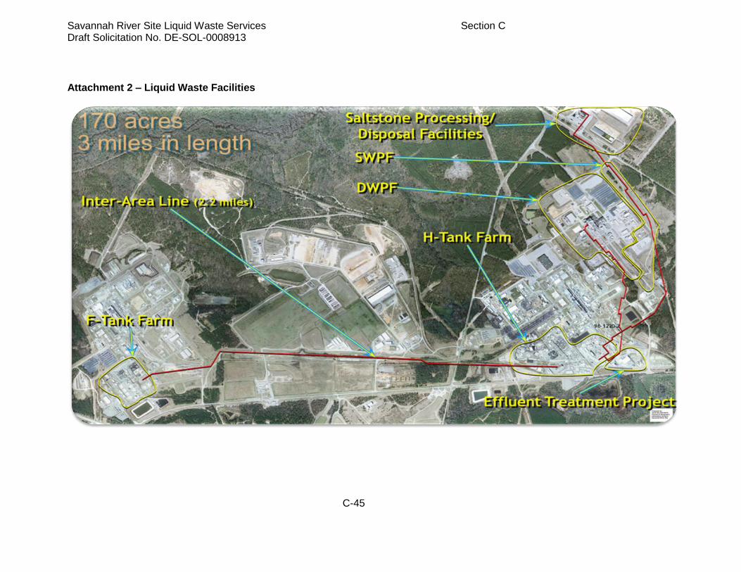
Savannah River Site Liquid Waste Services Section C Draft Solicitation No. DE-SOL-0008913
C-45
Attachment 2 – Liquid Waste Facilities

Savannah River Site Liquid Waste Services Section C Draft Solicitation No. DE-SOL-0008913
C-46
Attachment 3 – Schematic of the ARP/MCU Process

Savannah River Site Liquid Waste Services Section C Draft Solicitation No. DE-SOL-0008913
C-47
Attachment 4 – SRS Tank Closure Regulatory Roadmap
LW Contractor