part-i complete bidding document government of maharashtra i.e. after entering the details of...
TRANSCRIPT
1
Contractor No. of corrections Executive Engineer
STANDARD BIDDING DOCUMENT
PROCUREMENT OF CIVIL WORKS
PART-I
COMPLETE BIDDING DOCUMENT
NAME OF
WORK :
Construction of Proposed Office
Building on Plot No. C-47 'G' Block
at Bandra Kurla Complex (BKC)
Mumbai for Maharashtra Maritime
Board.
E-TENDER
B-II TENDER FORM

2
Contractor No. of corrections Executive Engineer
GOVERNMENT OF MAHARASHTRA
AGREEMENT NO---------------
NATIONAL COMPETITIVE BIDDING
(CIVIL WORKS)
Name of work : Construction of Secant pile for proposed office building of Maharashtra Maritime Board on plot no. 47, in G block, Bandra Kurla Complex, Bandra (East), Mumbai.
Tender Issue Date : Date.05.03.2018 at10.00 hrs.
Time and date of pre-bid
conference
: Date. 26.03.2018 at 15.00 hrs, Maharashtra Maritime
Board, Indian Mercantile Chamber, 3rd
floor, Ramjibhai Kamani Marg, Ballard Estate, Mumbai-400 001.
Opening Date
(If possible)
: Date. 20.04.2018 at 12.00 hrs Maharashtra Maritime
Board, Indian Mercantile Chamber, 3rd
floor, Ramjibhai Kamani Marg, Ballard Estate, Mumbai-400 001
Officer inviting bids Chief Executive Officer, Maharashtra Maritime Board, Indian Mercantile Chamber, 3rd floor, Ramjibhai Kamani Marg, Ballard Estate, Mumbai-400 001

3
Contractor No. of corrections Executive Engineer
GOVERNMENT OF MAHARASHTRA
MAHARASHTRA MARITIME BOARD
INVITATIONS FOR BIDS (IFB)
NATIONAL COMPETITIVE BIDDING
The Chief Executive Officer, Maharashtra Maritime Board, Indian Mercantile Chamber, 3rd floor, Ramjibhai Kamani Marg, Ballard Estate, Mumbai-400 001. Iinvites online bids for the
construction of work detailed in the table.
Sr. No.
Name of Work Approximate
value of work Rs.
Earnest Money Deposit
(Rs.)
Cost of Document
(Rs.)
Period of completion
1 Construction of Proposed
Office Building on Plot No. C-
47 'G' Block at Bandra Kurla
Complex (BKC) Mumbai for
Maharashtra Maritime Board.
57,76,30,280/- 28,88,000/- 11,200/-
24
(Twenty-
Four)
months
(Including
monsoon)
E-TENDER TIME SCHEDULE
Please Note: All bid related activities (Process) will be governed by the time schedule given under Key Dates
below:
Sr. No.
Activities Date Hour Mins.
1 Publishing Date 05.03.2018 At 10 00
2 Document Download start Date 05.03.2018 At 10 00
3 Document Download End Date 18.04.2018 Up to 17 00
4 Seek clarification start Date 05.03.2018 At 10 00
6 Seek clarification end Date 28.03.2018 Up to 17 00
5 Pre-Bid Meeting 26.03.2018 At 15 00
7 Bid Submission start Date 02.04.2018 At 10 00
8 Bid Submission closing Date 18.04.2018 Up to 17 00
9 Bid Opening Date *(If Possible) 20.04.2018 At 12 00
*Dates mentioned here, are scheduled dates for Bid Opening Activities. Any changes in dates of opening of technical and commercial tenders shall be notified in 'Press Notice / Corrigendum' section on the e-Tendering sub portal of the department before opening of the same.

4
Contractor No. of corrections Executive Engineer
Note:-
1. All eligible / interested Bidders are required to be enrolled on portal https://mahatenders.gov.in to
participate in e-tendering.
2. Bidders should submit the document related to tender, earnest money and tender document fee under
their digital signature online through payment gateway on the e tendering portal.
3. Other instructions can be seen in the tender form. All or any one of the tender may be rejected by
competent authority without assigning any reason.
PROCEDURE UNDER E-TENDERING INSTRUCTION TO BIDDERS
Tender form, conditions of contract, specifications and contract drawings can be
downloaded from https://mahatenders.gov.in after entering the details payment of
Rs. 11,200/- (Rupees Eleven Thousand Two Hundred Only) should be paid online
using payment gateway. The fees of tender document will be non refundable.
Further information regarding the work can be obtained from the above office.
Affidavit on Rs. 100/- stamp paper in prescribed form given in Annexure I sworn
before Executive Magistrate / Notary, Additional Performance Security Deposit (if
required) scan copy of original should be submitted online. Bids will be opened as per
the Tender Schedule, in the presence of such intending Tenderers or his / their
authorized representatives who may be present at that time.
TENDERING PROCEDURE :
1.1. Blank Tender Forms.
1.1.1 Tender Forms can be downloaded from the e-Tendering portal of Public Works
Department, Government of Maharashtra i.e. https://mahatenders.gov.in after
entering the details of payment towards Tender Fees as per the Tender Schedule.
1.1.2 The tender submitted by the tenderer shall be based on the clarification, additional
facility offered (if any) by the Department, and this tender shall be unconditional.
Conditional tenders will be summarily REJECTED.
1.1.3 All tenderers are cautioned that tenders containing any deviation from the
contractual terms and conditions, specifications or other requirements and
conditional tenders will be treated as non responsive. The contractor should clearly
mention in forwarding letter that his offer (in envelope No.1& 2) does not contain
any condition, deviations from terms and conditions stipulated in the tender.
1.1.4 Tenderers should have valid Class II / III Digital Signature Certificate (DSC)
obtained from any Certifying Authorities. In case of requirement of DSC, interested
Bidders should go to https://mahatenders.gov.in and follow the procedure
mentioned in the document ;Procedure for application of Digital Certificate.
1.1.5 For any assistance on the use of Electronic Tendering System, the Users may call

5
Contractor No. of corrections Executive Engineer
the below
Toll Free Ph. No. 1800 30702232/7878107985-86
E-Mail : [email protected]
1.2 PRE-TENDER CONFERENCE: -
1.2.1 Pre-tender conference open to all prospective tenderers who have purchased
tender form before the date of Pre-tender Conference, will be held at Mumbai on
Dated.26.03.2018 at 15.00 hrs Maharashtra Maritime Board, Indian Mercantile Chamber, 3rd
floor, Ramjibhai Kamani Marg, Ballard Estate, Mumbai-400 001, Phone No. (022)
22694475 wherein prospective Tenderers will have an opportunity to obtain clarifications
regarding the work and the Tender Conditions.
1.2.2 The prospective tenderers are free to ask for any additional information or
clarification either in writing or orally concerning the work, and the reply to the same will
be given by the Chief Engineer / Superintending Engineer / Executive Engineer, in
writing and this clarification referred to as Common Set of Conditions/Deviations
(C.S.D.), shall form part of tender documents and which will also be common and
applicable to all tenderers. The point/points if any raised in writing and/or verbally by the
contractor in pre-tender conference and not finding place in C.S.D. issued after the pre-
bid conference, is/are deemed rejected. In such case the provision in NIT shall prevail. No
individual correspondence shall be made thereafter with the contractor in this regard.
1.2.3 The tender submitted by the tenderer shall be based on the clarification, additional
facility offered (if any) by the Department, and this tender shall be unconditional.
Conditional tenders shall be summarily REJECTED.
1.2.4 All tenderers are cautioned that tenders containing any deviation from the
contractual terms and conditions, specifications or other requirements and conditional
tenders will be treated as non responsive. The contractor should clearly mention in
forwarding letter that his offer (in envelope No. 1& 2) does not contain any conditions,
deviations from terms and conditions stipulated in the tender.
1.3 Special Instructions to the Contractors/Bidders for the e-submission of the bids
online through this tender site : https://mahatenders.gov.in
(1) Bidder must register themselves on https://mahatenders.gov.in portal by clicking
“Online Bidder Enrollment” and then map Digital Signature certificate.
(2) Bidder then login to the site giving user id / password chosen during registration.
(3) The e-token that is registered should be used by the bidder and should not be
misused by others.
(4) The Bidders can update well in advance, the documents such as certificates,
purchase order details etc., under My Documents option and these can be selected
as per tender requirements and then attached along with bid documents during bid
submission.
(5) After downloading / getting the tender schedules, the Bidder should go through
them carefully and then submit the documents as asked, otherwise, the bid will be

6
Contractor No. of corrections Executive Engineer
rejected.
(6) If there are any clarifications, this may be obtained online through the tender site, or
through the contact details. Bidder should take into account of the corrigendum
published before submitting the bids online.
(7) Bidder, in advance, should get ready the bid documents to be submitted as indicated
in the tender schedule and they should be in PDF/xls/rar/dwf formats. If there is
more than one document, they can be clubbed together.
(8) Bidder should get ready the EMD as specified in the tender. The original should be
posted/couriered/given in person to the Tender Inviting Authority, within the bid
submission date & time for the tender.
(9) The bidder reads the terms & conditions and accepts the same to proceed further to
submit the bids.
(10) The bidder has to submit the tender document online well in advance before the
prescribed time to avoid any delay or problem during the submission process.
(11) After the bid submission, the acknowledgement number, given by the e-tendering
system should be printed by the bidder and kept as a record of evidence for online
submission of bid for the particular tender.
(12) The details of the Earnest Money Deposit document submitted physically to the
Dept and the scanned copies furnished at the time of bid submission online should
be the same otherwise the Tender will be summarily rejected
(13) The Tender Inviting Authority (TIA) will not be held responsible for any sort of
delay or the difficulties faced during the submission of bids online by the bidders.
(14) The bidder may submit the bid documents either by online mode through the site
(https://mahatenders.gov.in) as indicated in the tender.
(15) The tendering system will give a successful bid updating message after uploading
all the bid documents submitted & then a bid summary will be shown with the bid
no, date & time of submission of the bid with all other relevant details. The
documents submitted by the bidders will be digitally signed using the e-token of the
bidder and then submitted.
(16) The bid summary has to be printed and kept as an acknowledgement as a token of
the submission of the bid. The bid summary will act as a proof of bid submission
for a tender floated and will also act as an entry point to participate in the bid
opening date.
(17) Bidder should log into the site well in advance for bid submission so that he submits
the bid in time i.e. on or before the bid submission end time. If there is any delay,
due to other issues, bidder only is responsible.
(18) The bidder should see that the bid documents submitted should be free from virus
and if the documents could not be opened, due to virus, during tender opening, the
7
Contractor No. of corrections Executive Engineer
bid is liable to be rejected.
(19) The time settings fixed in the server side & displayed at the top of the tender site,
will be valid for all actions of requesting, bid submission, bid opening etc., in the e-
tender system. The bidders should follow this time during bid submission.
(20) All the data being entered by the bidders would be encrypted using PKI encryption
techniques to ensure the secrecy of the data. The data entered will not viewable by
unauthorized persons during bid submission & not be viewable by any one until the
time of bid opening. Overall, the submitted tender documents become readable only
after the tender opening by the authorized individual.
(21) The confidentiality of the bids is maintained since the secured Socket Layer 128 bit
encryption technology is used. Data storage encryption of sensitive fields is done.
(22) The bidders are requested to submit the bids through online etendering system to the
TIA well before the bid submission end date & time (as per Server System Clock).
(23) The bidder should logout of the tendering system using the normal logout option
available at the top right hand corner and not by selecting the (X) option in the
browser.
(24) The bidder should upload the Technical document in .rar format single file to
upload in Technical cover and then BOQ in .xls format single file to upload in
Finance cover.
(25) For any other queries, the bidders are asked to contact through Mail
8
Contractor No. of corrections Executive Engineer
SECTION 1 – INSTRUCTIONS TO BIDDERS (ITB)
Section – 1 : Instructions to Bidders
A. GENERAL
1. Scope of Bid
1.1 The Employer (named in Appendix to ITB) on pages No.24 invites online bids for the constructions
of works (as defined in these documents and referred to as “the works”) detailed in the table given in
IFB. The bidders may submit bids for any or all of the works detailed in the table given in IFB.
1.2 The successful bidder will be expected to complete the works by the intended completion date
specified in the Contract data.
1.3 Throughout these bidding documents, the terms ‘bid’ and ‘tender’ and their derivatives
(bidder/tenderer, bid/tender, bidding/tendering etc.) are synonymous.
2. Sources of Funds
3. The expenditure on this project will be met from the budget of "Maharashtra Maritime Board, 1A"
4. Eligible Bidders
4.1 This invitation for Bids is open to all bidders.
4.2 All bidders shall provide in Tender part-2 Section 2, page No.10 Forms of Bid and Qualification
Information, a statement that the Bidder is neither associated, nor has been associated, directly or
indirectly, with the Consultant or any other entity that has prepared the design, specification, and other
documents for the Project or being proposed as Project Manager for the Contract. A firm that has been
engaged by the Employer to provide consulting services for the preparation of supervision of the
works, and any of its affiliates, shall not be eligible to bid.
5. Qualification of the Bidder
5.1 All bidders shall provide in Section 2, Forms of Bid and Qualification Information, a preliminary
description of the proposed work method and schedule, including drawings and charts, as necessary.
The proposed methodology should include programme of construction backed with equipment
planning and deployment duly supported with broad calculations and quality assurance procedures
proposed to be adopted justifying their capability of execution and completion of work as per
technical specifications, within stipulated period of completion.
5.2 Deleted
5.3 If the Employer has not undertaken prequalification of potential bidders, all bidders shall include the
following information and documents with their bids in Section 2.
(a) Copies of original documents defining the constitution or legal status, place of registration
and principal place of business, written power of attorney of the signatory of the Bid to
commit the Bidder ;
(b) Total monetary value of construction work performed for each of the last five years ;
(c) Experience in works of a similar nature and size for each of the last five years and details of
works underway or contractually committed and clients who may be contacted for further
information on those contracts ;
(d) Major items of construction equipment proposed to carry out the Contract.
(e) Qualifications and experience of key site management and technical personnel proposed for
contract ;
9
Contractor No. of corrections Executive Engineer
(f) Reports on the financial standing of the Bidder, such as profit and loss statements and
auditor’s reports for the past five years ;
(g) Evidence of access to line(s) of credit and availability of other financial resources facilities
(10% of contract value) certified by the Bankers. (Not more than 3 months old);
(h) Undertaking that the bidder will be able to invest a minimum cash up to 25% of contract
value of work during implementation of work ;
(i) Authority to seek references from the Bidder’s bankers ;
(j) Information regarding any litigation, current or during the last five years, in the Bidder is
involved, the parties concerned and disputed amount ;
4.5 QUALIFICATION CRITERIA
4.5.1 Qualification will be based on Applicant’s meeting all the following minimum pass/fail criteria
regarding the Applicant’s general and particular experience, personnel and equipment capabilities,
and financial position, as demonstrated by the Applicant’s response in the forms attached to the
Letter of Application. Subcontractor’s experience and resources shall not be taken into account in
determining the Applicant’s compliance with the qualifying criteria.
To qualify for more than one contract, the applicant must demonstrate having experience and
resources sufficient to meet the aggregate of the qualifying criteria for each contract given in the
paragraphs 4.5.4, 4.5.5, 4.5.6 and 4.5.9 below.
4.5.2 Base year and escalation: -The base shall be taken as 2017-18
Following enhancement factors will be used for the cost of works executed and the financial figures
to a common base value for works completed in India.
Year before Multiplying factor
One 1.10
Two 1.21
Three 1.33
Four 1.46
Five 1.61
Applicant should indicate actual figures of costs and amount for the works executed by them without
accounting for the above mentioned factors.
In case the financial figures and value of completed works are in foreign currency, the above
enhanced multiplying factors will not be applied. Instead, current market exchange rate (State Bank of
India BC selling rate as on the last date of submission of bid) will be applied for the purpose of
conversion amount in foreign currency in Indian rupees.
4.5.3 General Experience
The applicant shall meet the following minimum criteria
(a) To qualify for award of the contract, each tenderer in his name should have achieved an
Minimum financial turnover of Rs. 60,00,00,000.00 during last three years ( FY 2014-15 ,
2015-16, 2016-17) at the price level of 2017-2018 information should be given in Performa
given This should be duly audited by Chartered Accountant. Year in which no turnover is
shown would also be considered for working out the average turnover.
(b) Satisfactorily completed as a contractor, at least one similar type of work, Construction of
value Rs. 43,32,00,000.00 at the price level of 2017-2018.
10
Contractor No. of corrections Executive Engineer
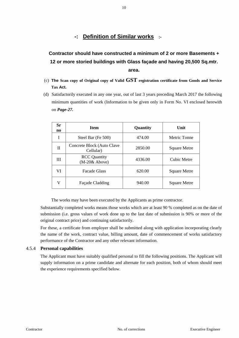
-: Definition of Similar works :-
Contractor should have constructed a minimum of 2 or more Basements +
12 or more storied buildings with Glass façade and having 20,500 Sq.mtr.
area.
(c) The Scan copy of Original copy of Valid GST registration certificate from Goods and Service
Tax Act.
(d) Satisfactorily executed in any one year, out of last 3 years preceding March 2017 the following
minimum quantities of work (Information to be given only in Form No. VI enclosed herewith
on Page-27.
Sr
no Item Quantity Unit
I Steel Bar (Fe 500) 474.00 Metric Tonne
II Concrete Block (Auto Clave
Cellular) 2850.00 Square Metre
III RCC Quantity
(M-20& Above) 4336.00 Cubic Metre
VI Facade Glass 620.00 Square Metre
V Façade Cladding 940.00 Square Metre
The works may have been executed by the Applicants as prime contractor.
Substantially completed works means those works which are at least 90 % completed as on the date of
submission (i.e. gross values of work done up to the last date of submission is 90% or more of the
original contract price) and continuing satisfactorily.
For these, a certificate from employer shall be submitted along with application incorporating clearly
the name of the work, contract value, billing amount, date of commencement of works satisfactory
performance of the Contractor and any other relevant information.
4.5.4 Personal capabilities
The Applicant must have suitably qualified personal to fill the following positions. The Applicant will
supply information on a prime candidate and alternate for each position, both of whom should meet
the experience requirements specified below.
11
Contractor No. of corrections Executive Engineer
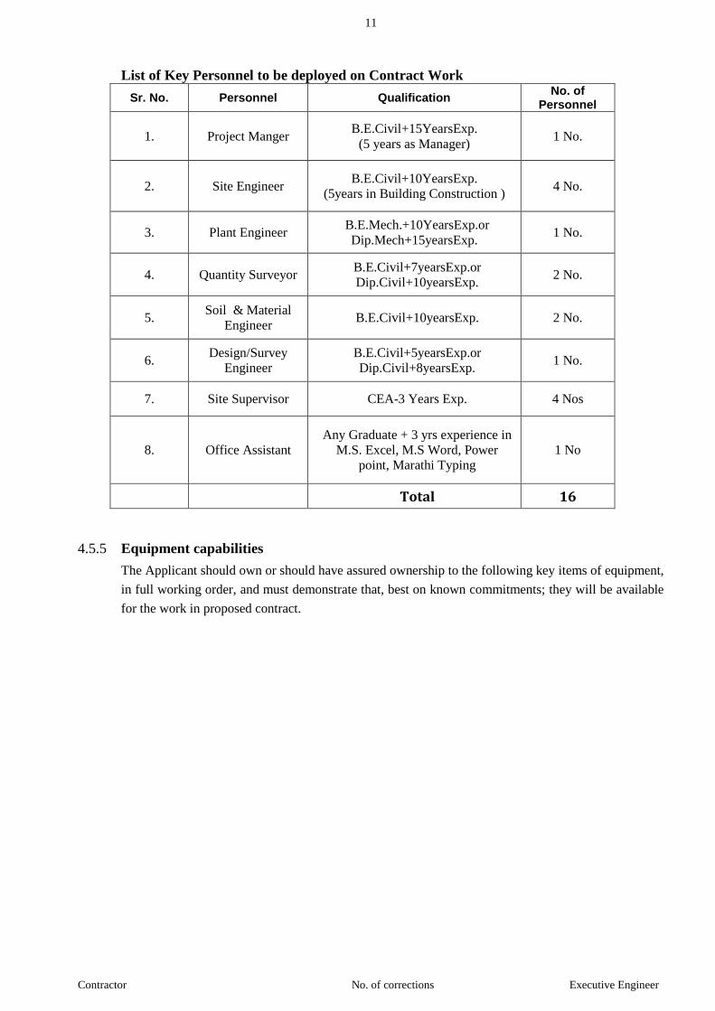
List of Key Personnel to be deployed on Contract Work
Sr. No. Personnel Qualification No. of
Personnel
1. Project Manger B.E.Civil+15YearsExp.
(5 years as Manager) 1 No.
2. Site Engineer B.E.Civil+10YearsExp.
(5years in Building Construction ) 4 No.
3. Plant Engineer B.E.Mech.+10YearsExp.or
Dip.Mech+15yearsExp. 1 No.
4. Quantity Surveyor B.E.Civil+7yearsExp.or
Dip.Civil+10yearsExp. 2 No.
5. Soil & Material
Engineer B.E.Civil+10yearsExp. 2 No.
6. Design/Survey
Engineer
B.E.Civil+5yearsExp.or
Dip.Civil+8yearsExp. 1 No.
7. Site Supervisor CEA-3 Years Exp. 4 Nos
8. Office Assistant
Any Graduate + 3 yrs experience in
M.S. Excel, M.S Word, Power
point, Marathi Typing
1 No
Total 16
4.5.5 Equipment capabilities
The Applicant should own or should have assured ownership to the following key items of equipment,
in full working order, and must demonstrate that, best on known commitments; they will be available
for the work in proposed contract.
12
Contractor No. of corrections Executive Engineer
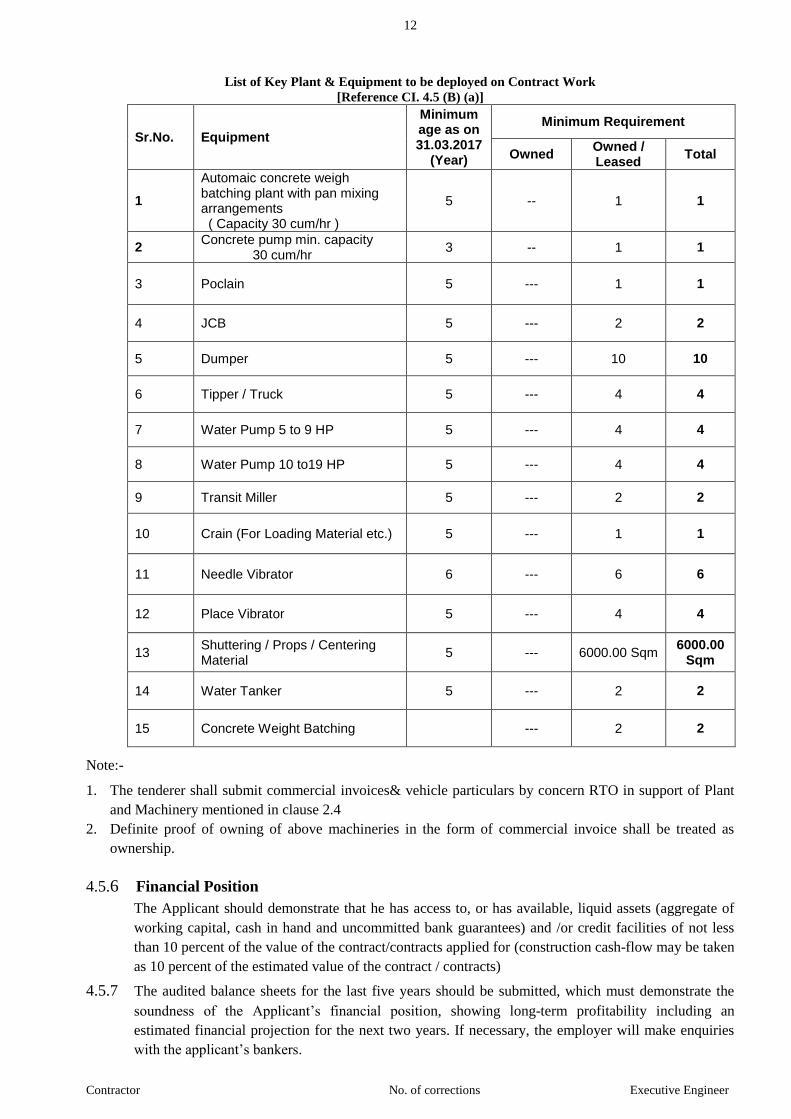
List of Key Plant & Equipment to be deployed on Contract Work
[Reference CI. 4.5 (B) (a)]
Sr.No. Equipment
Minimum age as on 31.03.2017
(Year)
Minimum Requirement
Owned Owned / Leased
Total
1
Automaic concrete weigh batching plant with pan mixing arrangements ( Capacity 30 cum/hr )
5 -- 1 1
2 Concrete pump min. capacity 30 cum/hr
3 -- 1 1
3 Poclain 5 --- 1 1
4 JCB 5 --- 2 2
5 Dumper 5 --- 10 10
6 Tipper / Truck 5 --- 4 4
7 Water Pump 5 to 9 HP 5 --- 4 4
8 Water Pump 10 to19 HP 5 --- 4 4
9 Transit Miller 5 --- 2 2
10 Crain (For Loading Material etc.) 5 --- 1 1
11 Needle Vibrator 6 --- 6 6
12 Place Vibrator 5 --- 4 4
13 Shuttering / Props / Centering Material
5 --- 6000.00 Sqm 6000.00
Sqm
14 Water Tanker 5 --- 2 2
15 Concrete Weight Batching --- 2 2
Note:-
1. The tenderer shall submit commercial invoices& vehicle particulars by concern RTO in support of Plant
and Machinery mentioned in clause 2.4
2. Definite proof of owning of above machineries in the form of commercial invoice shall be treated as
ownership.
4.5.6 Financial Position
The Applicant should demonstrate that he has access to, or has available, liquid assets (aggregate of
working capital, cash in hand and uncommitted bank guarantees) and /or credit facilities of not less
than 10 percent of the value of the contract/contracts applied for (construction cash-flow may be taken
as 10 percent of the estimated value of the contract / contracts)
4.5.7 The audited balance sheets for the last five years should be submitted, which must demonstrate the
soundness of the Applicant’s financial position, showing long-term profitability including an
estimated financial projection for the next two years. If necessary, the employer will make enquiries
with the applicant’s bankers.

13
Contractor No. of corrections Executive Engineer
4.5.8 Litigation History
The Applicant should provide accurate information on any litigation or arbitration resulting from
contracts completed or under execution by him over the last five years. A consistence history of
awards against the applicant or any partner of a joint venture may result in failure of the applicant.
4.5.9 Bid Capacity
Applicant who meets the minimum qualification criteria will be qualified only if their available bid
capacity is more than the total bid value. The available bid capacity will be calculated as under:
Assessed Available Bid capacity = (A x N x 2 - B),
Where,
A = Highest turnover of last five years (updated to the current price level ) rate of inflation may be
taken as 10 percentage per year which will taking into account the completed as well as works in
progress.
B = Value at current price level of the existing commitments and ongoing works to be completed
during the next 12 months, and
N = Number of years prescribed for completion of the works for which bids are invited.
4.6. Disqualification
Even though the applicants meet the above qualifying criteria, they are subject to be disqualified if
they have:
made misleading or false representation in the form, statements submitted; and / or
Records of poor performance such as abandoning the works, rescinding of contract
for which the reasons are attributable to the non-performance of the contractor,
consistent history of litigation awarded against the Applicant or financial failure due
to bankruptcy.
The rescinding of contract of a joint venture on account of reasons other than non-
performance, such as Most Experienced partner of joint venture pulling out, court
directions leading to breaking up to a joint venture before the start of work, which are
not attributable to the poor performance of the contractor will, however, not affect the
qualification of the individual partners.
4.7 JOINT VENTURE - DELETED (Not Allowed )
5. One Bid per Bidder
5.1 Each bidder shall submit only one online - bid for one package. A bidder who submits or participates in
more than one Bid (other than as a sub contractor or on cases of alternatives that have been permitted
or requested) will cause all the proposals with the Bidder's participation to be disqualified.
6. Cost of Bidding
6.1 The bidder shall bear all costs associated with the preparation and submission of his bid and the
Employer will in no case be responsible and liable for those costs.
7. Site Visit
7.1 The Bidder, at the Bidder's own responsibility and risk is encouraged to visit and examine the Site of
Works and its surrounding and obtain all information that may be necessary for preparing the Bid and
14
Contractor No. of corrections Executive Engineer
entering into a contract for construction of the Works. The cost of visiting the Site shall be at the
Bidder's own expense.
8. Additional Requirements
8.1 Bidders should provide any additional information required to fulfil the requirements of clause 4 of the
Instructions to the Bidders, if applicable.
(i) Affidavit
(ii) Undertaking.
(iii) Affidavit additional performance security must be enclosed
15
Contractor No. of corrections Executive Engineer
B. BIDDING DOCUMENTS
8. Content of Bidding Documents
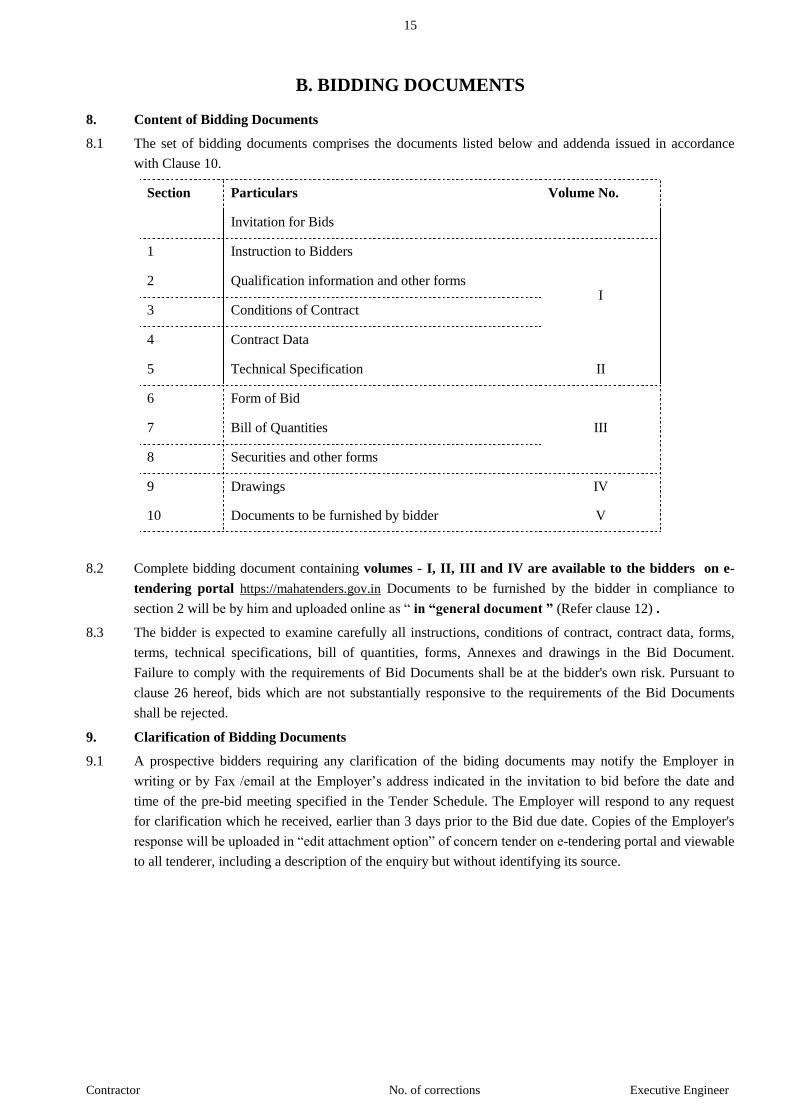
8.1 The set of bidding documents comprises the documents listed below and addenda issued in accordance
with Clause 10.
Section Particulars Volume No.
Invitation for Bids
1 Instruction to Bidders
I 2 Qualification information and other forms
3 Conditions of Contract
4 Contract Data
5 Technical Specification II
6 Form of Bid
III 7 Bill of Quantities
8 Securities and other forms
9 Drawings IV
10 Documents to be furnished by bidder V
8.2 Complete bidding document containing volumes - I, II, III and IV are available to the bidders on e-
tendering portal https://mahatenders.gov.in Documents to be furnished by the bidder in compliance to
section 2 will be by him and uploaded online as “ in “general document ” (Refer clause 12) .
8.3 The bidder is expected to examine carefully all instructions, conditions of contract, contract data, forms,
terms, technical specifications, bill of quantities, forms, Annexes and drawings in the Bid Document.
Failure to comply with the requirements of Bid Documents shall be at the bidder's own risk. Pursuant to
clause 26 hereof, bids which are not substantially responsive to the requirements of the Bid Documents
shall be rejected.
9. Clarification of Bidding Documents
9.1 A prospective bidders requiring any clarification of the biding documents may notify the Employer in
writing or by Fax /email at the Employer’s address indicated in the invitation to bid before the date and
time of the pre-bid meeting specified in the Tender Schedule. The Employer will respond to any request
for clarification which he received, earlier than 3 days prior to the Bid due date. Copies of the Employer's
response will be uploaded in “edit attachment option” of concern tender on e-tendering portal and viewable
to all tenderer, including a description of the enquiry but without identifying its source.
16
Contractor No. of corrections Executive Engineer
9.2 Pre-bid meeting
9.2.1 The bidder or his official representative is invited to attend a pre-bid meeting which will take place at the
address, venue, time and date as indicated in NIT.
9.2.2 The purpose of the meeting will be to clarify issues and to answer questions on any matter that may be
raised at that stage.
9.2.3 The bidder is requested to submit any questions in writing by fax or by e-mail to reach the Employer well
before the date & time of the pre-bid meeting.
9.2.4 Minutes of the meeting, including the text of the questions raised (without identifying the source of
enquiry) and the responses given will be transmitted by uploading on e-tender portal without delay for
information to all intended bidder. Any modifications of the bidding documents listed in sub clause 8.1
which may become necessary as a result of the pre-bid meeting shall be made by the Employer exclusively
through the issue of an Addendum pursuant to clause 10 and not through the minutes of the pre-bid
meeting.
9.2.5 Non-attendance at the pre-bid meeting will not be a cause for disqualification of a bidder.
10. Amendment of Biding Documents
10.1 Before the deadline for submission of bids online, the Employer may modify the bidding documents by
issuing addenda.
10.2 Any addendum thus issued shall be part of the bidding documents and shall be uploaded in “edit
attachment option” of concern tender on e-tendering portal and viewable to all tenderer, including a
description of the enquiry but without identifying its source. The uploading of addendum on e-tendering
portal shall deemed to be acknowledgement of receipt of each addendum to the employer. The Employer
will assume no responsibility for non cognizance by the bidders.
10.3 To give prospective bidders reasonable time in which to take an addendum into account in preparing their
bids, the Employer may, at his discretion, extend as necessary the deadline for submission of bids, in
accordance with Sub-Clause 20.2 below.
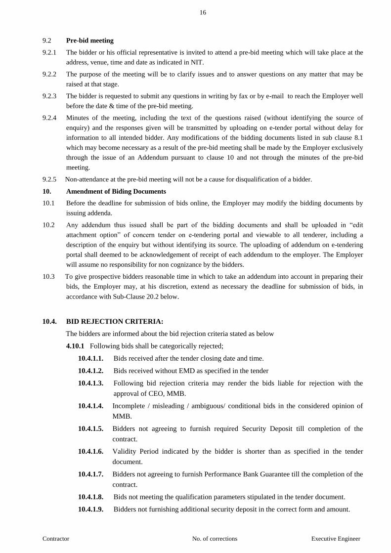
10.4. BID REJECTION CRITERIA:
The bidders are informed about the bid rejection criteria stated as below
4.10.1 Following bids shall be categorically rejected;
10.4.1.1. Bids received after the tender closing date and time.
10.4.1.2. Bids received without EMD as specified in the tender
10.4.1.3. Following bid rejection criteria may render the bids liable for rejection with the
approval of CEO, MMB.
10.4.1.4. Incomplete / misleading / ambiguous/ conditional bids in the considered opinion of
MMB.
10.4.1.5. Bidders not agreeing to furnish required Security Deposit till completion of the
contract.
10.4.1.6. Validity Period indicated by the bidder is shorter than as specified in the tender
document.
10.4.1.7. Bidders not agreeing to furnish Performance Bank Guarantee till the completion of the
contract.
10.4.1.8. Bids not meeting the qualification parameters stipulated in the tender document.
10.4.1.9. Bidders not furnishing additional security deposit in the correct form and amount.
17
Contractor No. of corrections Executive Engineer
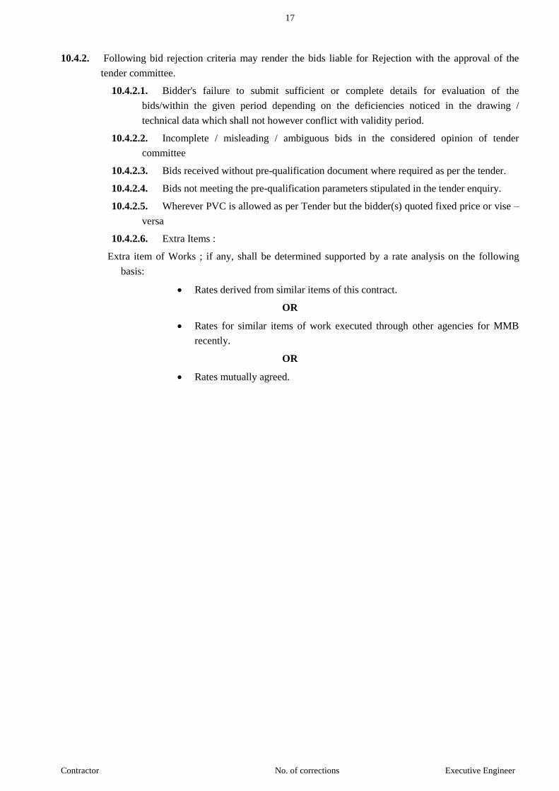
10.4.2. Following bid rejection criteria may render the bids liable for Rejection with the approval of the
tender committee.
10.4.2.1. Bidder's failure to submit sufficient or complete details for evaluation of the
bids/within the given period depending on the deficiencies noticed in the drawing /
technical data which shall not however conflict with validity period.
10.4.2.2. Incomplete / misleading / ambiguous bids in the considered opinion of tender
committee
10.4.2.3. Bids received without pre-qualification document where required as per the tender.
10.4.2.4. Bids not meeting the pre-qualification parameters stipulated in the tender enquiry.
10.4.2.5. Wherever PVC is allowed as per Tender but the bidder(s) quoted fixed price or vise –
versa
10.4.2.6. Extra Items :
Extra item of Works ; if any, shall be determined supported by a rate analysis on the following
basis:
Rates derived from similar items of this contract.
OR
Rates for similar items of work executed through other agencies for MMB
recently.
OR
Rates mutually agreed.
18
Contractor No. of corrections Executive Engineer
C. PREPARATION OF BIDS
11. Language of the Bid
11.1 All documents relating to the bid shall be in the English language.
12. Documents Comprising the Bid
12.1 The bid to be submitted by the bidder as Volume V of the bid document (refer Clause 8.1) shall be in
two separate parts:
Part I shall be named "Technical Bid" and shall comprise
(i) Bid Security in the form specified in section 8
(ii) Qualification Information and supporting documents as specified in Sect. 2.
(iii) Certificates, undertakings, affidavits as specified in Section 2.
(iv) Any other information pursuant to Claus 4.2 of these instructions.
(v) Undertaking that the bid shall remain valid for the period specified in Cl 15.1.
(vi) Acceptance/ non acceptance of Dispute Review Expert proposed in Cl. 36.1.
Part II shall be named "Financial Bid" and shall comprise
(i) Form of Bid a specified in Section 6.
(ii) Priced Bill of Quantities for items specified in Section 7.
12.2 The bidder shall fill and upload the Technical and Financial bid in ‘edit attachment option’ and shall
upload the supporting document in ‘General Document Option’ of e tendering portal and submit the
bid by using his Class III Digital Signature.
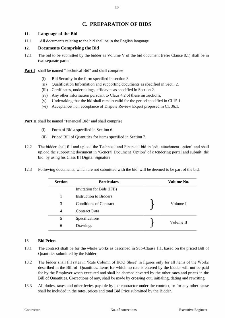
12.3 Following documents, which are not submitted with the bid, will be deemed to be part of the bid.
Section Particulars Volume No.
Invitation for Bids (IFB)
1 Instruction to Bidders
} Volume I 3 Conditions of Contract
4 Contract Data
5 Specifications
} Volume II
6 Drawings
13 Bid Prices.
13.1 The contract shall be for the whole works as described in Sub-Clause 1.1, based on the priced Bill of
Quantities submitted by the Bidder.
13.2 The bidder shall fill rates in ‘Rate Column of BOQ Sheet’ in figures only for all items of the Works
described in the Bill of Quantities. Items for which no rate is entered by the bidder will not be paid
for by the Employer when executed and shall be deemed covered by the other rates and prices in the
Bill of Quantities. Corrections of any, shall be made by crossing out, initialing, dating and rewriting.
13.3 All duties, taxes and other levies payable by the contractor under the contract, or for any other cause
shall be included in the rates, prices and total Bid Price submitted by the Bidder.
19
Contractor No. of corrections Executive Engineer
13.4 The rates and prices quoted by the bidder are subject to adjustment during the performance of the
Contract in accordance with the provisions of Clause 47 of the Conditions of Contract. (For contracts
more than 24 month’s period).
14. Currencies of Bid and Payment.
The unit rates and the prices shall be quoted by the bidder entirely in Indian Rupees. All payments
shall be made in Indian Rupees.
The Rates of Items in schedule "B" / (BOQ) on part II of NIT are including of Taxes, Rates,
Cesses and also inclusive of the livable tax in respect of sale by transfer of property in goods
involved in the execution of works Contract under the provision of rule 58 of the Maharashtra
Value Added Tax Act 2005 for the purpose of levy of
The rates quoted by the Contractor shall be rates excluding sales Tax and all other taxes but
shall include GST that the contractor will have to pay for the performance of this Contract.
GST as per Govt. of Maharashtra Finance Department, Marathi Circular No. GST-2017/ ¯ÖÏ. ÛÎú. 81 / Ûú¸üÖ¬ÖÖ®Ö-1 Mantralaya, Mummbai-32, Dated. 19.08.2017.
Provisional amount of GST @2% i.e.1% C.G.S.T. + 1% S.G.S.T. will be deducted at Source
(TDS) after the enforcement of Sections 51 of Maharashtra Goods and Services Act. 2017.
15. Bid Validity.
15.1 Bids shall remain valid for a period not less than 120 days after the deadline date for bid submission
specified in Clause 20. A bid valid for a shorter period shall be rejected by the Employer as non-
responsive. In case of discrepancy in bid validity period between that given in the undertaking
pursuant to Clause 12.1 (v) and the Form of Bid submitted by the bidder, the latter shall be deemed to
stand corrected in accordance with the former and the bidder has to provide for any additional security
that is required.
15.2 In exceptional circumstances, prior to expiry of the original time limit, the Employer may request that
the bidders may extend the period of validity for a specified additional period. The request and the
bidder's responses shall be made in writing or by cable. A bidder may refuse the request without
forfeiting his bid security. A bidder agreeing to the request will not be required or permitted to modify
his bid except as provided in 15.3 hereinafter, but will be required to extend the validity of his bid
security for a period of the extension, and in compliance with Clause 16 in all respects.
15.3 * In the case of contracts in which the Contract Price is fixed (not subject to price adjustment), in the
event that the Employer requests and the Bidder agrees to an extension of the validity period, the
contract price, if the bidder is selected for award shall be the bid price corrected as follows:
The price shall be increased by the factor of 0.2% for each week or part of a week that has elapsed
from the expiration of the initial bid validity to the date of issue of letter of acceptance to the
successful Bidder.
* DELETED
15.4 Bid evaluation will be based on the bid prices without taking into consideration the above
correction.

20
Contractor No. of corrections Executive Engineer
15.5 Hard copy submitting by contractor.
Tenderer must submit the Hard Copy of online submitted copy of the Concerned Executive
Engineer's Office(as specified below)
a) Documents submitted on time in Envelope No. 1 & 2 are put in separate Envelope as Envelope
No.1 (Technical Bid) and Envelope No.2 (Financial Bid) respectively and sealed properly.
b) The above two sealed Envelopes No.1 and 2 shall be again put together in one common cover
and sealed. The name of work, online Tender Number, Name and full address of Tenderer with
Mobile Number shall be mentioned on the said common cover marked sealed. Common cover
properly covers corner.
c) The above Common Cover containing Envelope No. 1 & 2 must be submit to the Concerned
Executive Engineer, Maharashtra Maritime Board, Mumbai. Within 03 working days start
form next day of after Closing of Bid Submission Date (During Office Hours) Only.
d) No Delay on account of any cause will be entertained for the receipt said Hard Copy.
e) If Tenderer Fails or neglect to Submit Hard Copy His On-Line offer (Tender) will be Not be
considered for further tendering procedure.
16. Bid Security
16.1 Earnest money of minimum Rs. 22,92,000/- shall be paid via online payment gateway mode. After
Tender opening, the EMD of the unsuccessful bidder will be returned to account provided by the
bidder during the bid preparation as given in challan under Beneficiary Account Number.
16.2 Earnest Money in the form of cheques or any other form except above will not be accepted.
16.3 The amount will be refunded to the unsuccessful tenderers on deciding about the acceptance or
otherwise of the tender. In case of successful tenderer, it will be refunded on his paying initial
Security Deposit and completing the tender documents in form B-2.
16.4 Joint Venture Not Allowed .
16.5 The Bid Security of the successful bidder will be discharged when the bidder has signed the
Agreement and furnished the required Performance Security.
16.6 The bid Security may be forfeited.
I/We agree that the offer shall remain open for acceptance for a minimum period of 120 days from
the date fixed for opening of envelope No. 2 (Financial Bid) and thereafter until it is withdrawn by
me/ us by notice in writing duly addressed to the authority opening the tenders and sent by registered
post A.D. or otherwise delivered at the office of such authority. of the sum of Rs. 22,92,000/-
representing the earnest money is herewith forwarded. The amount of earnest money shall not bear
interest and shall be liable to be forfeited to the Government, should I/We fail to (I) abide by the
stipulation to keep the offer open for the period mentioned above or (II) Sign and complete the
contract documents as required by the Engineer and furnish the security deposit as specified in item
(d) of the memorandum contained in paragraph (1) above within the time limit laid down in clause (1)
of the annexed General Conditions of contract. The amount of earnest money may be adjusted towards
the security deposit or refunded to me/us if so, desired by me/ us in writing, unless the same or any
part thereof has been forfeited as aforesaid.
16.7 I/We have secured exemption from payment of earnest money after executing the necessary bond in
favour of the Government, a true copy of which is enclosed herewith. Should any occasion for
forfeiture of earnest money for this work arise due to failure on my/our part to (I) abide by the

21
Contractor No. of corrections Executive Engineer
stipulations to keep the offer open for the period mentioned above or (ii) sign and complete the
contract documents and furnish the security deposit as specified in item (d) of the Memorandum
contained in paragraph (1) above within the time limit laid down in clause (1) of the annexed General
Conditions of Contract, the amount payable by me/us may, at the option of the Engineer, be
recovered out of the amount deposited in lump sum for securing exemption in so far as the same may
extend in terms of the said bond and in the event of the deficiency out of any other payments which
are due or payable to me/us by the Government under any other contract or transaction of any nature
whatsoever or otherwise.
17. Alternative Proposals by Bidders
17.1 Bidders shall submit offers that fully comply with the requirements of the bidding documents,
including the conditions of contract (including mobilization advance or time for completion), basic
technical design as indicated in the drawing and specifications. Conditional offer or alternative
offers will not be considered further in the process of tender evaluation.
18. Format and Signing of Bid
18.1 The bidder shall be required to fill and upload the Technical and Financial Bid by using his Class III
Digital Signature of the person who is authorised to submit the Bid, uploaded
18.2 The documents are required to be uploaded in “Edit Attachment Option” online. The bidder is
required to ensure that the size of each document does not exceed 5 MB.
18.3 In case Bidder would like to provide any Supporting Document(s) as a part of the Bid Response, the
Bidder may upload such Supporting Document(s) under “General Document Option” of tender.
18.4 CASHLESS
Vide GR No. Govt. Of Maharashtra , Public Works Department. Mantralaya Nagpur No. Tender
2016/CN20/shikana/Bldg -2 dated 09/12/2016 Contractor shall submit a certificate to the effect that
all the payments to the labour / staff are made in bank accounts of staff should linked to Unique
Identification Number ( AADHAR Card) . The certification shall be submitted by the contractor
within 60 days from the commencement of the contract. If the time period of contract is less than 60
days than such certificate shall be submitted within 15 days from the date of commencement of
contract.

22
Contractor No. of corrections Executive Engineer
D. SUBMISSION OF BIDS
19. Submission of Bids
19.1 The Bidder shall refer to the "Bidder Manual Kit'' for Preparation and Submission of bid on
'https://mahatender.gov.in' portal.
20. Deadline for Submission of the Bids
20.1 The complete Bids (including Technical and Financial) must be received on e-tendering portal not
later than the date indicated in NIT.
20.2 The Employer may extend the deadline for submission of bids by issuing an amendment in
accordance with Clause 10, in which case all rights and obligations of the Employer and the bidders
previously subject to the original deadline will then be subject to the new deadline.
21. Late Bids
21.1 Any bid submitting the Bid Security and Cost of Tender Fee document in Original after deadline
prescribed in NIT will not be accepted and returned. The bid (including technical and financial) will
not be opened. The complete Bids (including Technical and Financial) must be received by the
Employer online not later than the deadline indicated in the schedule.
22. Modification and Withdrawal of Bids
22.1 The bidder may modify or cancel their bid online only before the deadline prescribed in clause 20
i.e..Bid due date.

23
Contractor No. of corrections Executive Engineer
E. BID OPENING AND EVALUATION
23. Bid Opening
23.1 The Employer will open all the Technical Bids received of those tenderer who has submitted the Bid
Security and Cost of Tender Fee document through online before the deadline prescribed in Tender
Schedule, in the presence of the Bidders or their representatives who choose to attend at time, date
and the place specified in Appendix in the manner specified in Clause 20 and 23.2. In the event of the
specified date of Bid opening being declared a holiday for the Employer, the Bids will be opened at
the appointed time and location on the next working day.
23.2 The Online "Technical Bid" shall be opened first. The Bid Security and Cost of Tender Fee
documents uploaded online shall be verified with Original documents submitted by bidders as
required as per NIT. The amount, form and validity of the bid security furnished with each bid will be
announced. If the bid security furnished does not conform to the amount and validity period as
specified in the Invitation for Bid (ref. Column 5 and paragraph 3), and has not been furnished in the
form specified in Clause 16, the remaining technical bid online will not be opened .
23.3 (i) Subject to confirmation of the bid security by the issuing Bank, the bids accompanied with valid
bid security will be taken up for evaluation with respect to the Qualification Information and
other information furnished in Part I of the bid pursuant to Clause 12.1.
(ii) After receipt of confirmation of the bid security, the bidder will be asked in writing/ online
(usually within 10 days of opening of the Technical Bid) to clarify or modify his technical bid,
if necessary, with respect to any rectifiable defects.
(iii) The bidders will respond in not more than 7 days of issue of the clarification letter/online
communication, which will also indicate the date, time and venue of opening of the financial
Bid. (usually on the 21st day of opening of the Technical Bid)
(iv) Immediately (usually within 3 or 4 days) on receipt of these clarifications the Evaluation
Committee will finalize the list of responsive bidders whose financial bids are eligible for
consideration.
23.4 At the time of Online opening of "Financial Bid", the names of the bidders who were found
responsive in accordance with Clause 23.3 (iv) will be announced. The bids of only these bidders will
be opened. The remaining bids will be rejected online. The e-tendering system shall communicate to
the rejected bidders along with reasons for their rejection. The responsive Bidder's names, the Bid
prices, the total amount of each bid, will be announced by the Employer at the opening.
23.5 In case bids are invited in more than one package, the order for opening of the "Financial Bid" shall
be that in which they appear in the "Invitation For Bid".
23.6 The Employer shall prepare minutes of the Bid opening, including the information disclosed to those
present in accordance with Sub-Clause 23.4. result of financial bids of all the Bidders shall be made
available e-tendering portal in option “ tender free View”
24. Process to be Confidential
24.1 Information relating to the examination, clarification, evaluation and comparison of Bids and
recommendations for the award of a contractor shall not be disclosed to Bidders or any other persons
not officially concerned with such process until the award to the successful Bidder has been
announced. Any effort by a Bidder to influence the Employer's processing of Bids or award decisions
may result in the rejection of his Bid.

24
Contractor No. of corrections Executive Engineer
25. Clarification of Financial Bids
25.1 To assist in the examination, evaluation and comparison of Bids, the Employer may, at his discretion,
ask any Bidder for clarification of his bid, including breakdowns of unit rates. The request for
clarification and the response shall be in writing but no change in the price or substance of the Bid
shall be sought, offered, or permitted except as required to confirm the correction of arithmetic errors
discovered by the Employer in the evaluation of the Bids in accordance with Clause 27
25.2 Subject to sub-clause 25.1, no Bidder shall contact the Employer on any matter relating to his bid
from the time of the bid opening to the time the contract is awarded. If the Bidder wishes to bring
additional information to the notice of the Employer, it should do so in writing/online.
25.3 Any effort by the Bidder to influence the Employer in the Employer's bid evaluation, bid comparison
or contract award decisions may result in the rejection of the Bidder's bid.
26. Examination of Bids and determination of Responsiveness
26.1 During the detailed evaluation of "Technical Bids" the Employer will determine whether each Bid (a)
meets the eligibility criteria defined in clause 3 and 4. (b) has been properly signed, (c) is
accompanied by the required securities and, (d) is substantially responsive to the requirements of the
Bidding documents. During the detailed evaluation of the "Financial Bid", the responsiveness of the
bids will be further determined with respect to the remaining bid conditions, i.e. priced bill of
quantities, technical specifications and drawings.
26.2 A substantially responsive “Financial Bid” is one, which conforms to all the terms, conditions and
specifications of the Bidding documents, without material deviation or reservation. A material
deviation or reservation is one (a) which affects in any substantial way the scope, quality, or
performance of the Works, (b) which limits in any substantial way, inconsistent, with the Bidding
documents, the Employer’s rights or the Bidder’s obligations under the Contract, or (c) whose
rectification would affect unfairly the competitive position of other Bidders presenting substantially
responsive Bids.
26.3 If a “Financial Bid” is not substantially responsive, it will be rejected by the Employer, and may not
subsequently be made responsive by correction or withdrawal of the non-conforming deviation or
reservation.
27. Correction of Errors
27.1 “Financial Bids” determined to be substantially responsive will be checked by the Employer for any
arithmetic errors. Errors will be corrected by the Employer as follows :
(a) where there is a discrepancy between the rates in figures and in words, the rate in
words will govern ; and
(b) where there is a discrepancy between the unit rate and the line item total resulting
from multiplying the unit rate by the quantity, the unit rate as quoted will govern.
27.2 The amount stated in the “Financial Bid” will be corrected by the Employer in accordance with the
above procedure and the bid amount adjusted with the concurrence of the Bidder in the following
manner :
(a) If the Bid price increases as a result of these corrections, the amount as stated in the
bid will be the ‘bid price’ and the increase will be treated as rebate;
(b) If the bid price decreases as a result of the corrections, the decreased amount will be
treated as the ‘bid price’.
Such adjusted bid price shall be considered as binding upon the Bidder. If the Bidder does not accept
the corrected amount the Bid will be rejected and the Bid Security may be forfeited in accordance
with Sub-Clause 16.6(b).
28. Deleted

25
Contractor No. of corrections Executive Engineer
29. Evaluation and Comparison of Financial Bids
29.1 The Employer will evaluate and compare only the Bids determined to be substantially responsive in
accordance with Sub-Clause 26.2.
29.2 In evaluating the Bids, the Employer will determine for each Bid the evaluated Bid Price by adjusting
the Bid Price as follows:
a) Making any correction for errors pursuant to Clause 27; or
(b) Making an appropriate adjustments for any other acceptable variations, deviations; and
(c) Making appropriate adjustments to reflect discounts or other price modifications offered in
accordance with Sub-Clause 23.6.
29.3 The Employer reserves the right to accept or reject any variation or deviation. Variations and
deviations and other factors, which are in excess of the requirements of the Bidding documents or
otherwise result in unsolicited benefits for the Employer shall not be taken into account in Bid
evaluation.
29.4 The estimated effect of the price adjustment conditions under Clause 47 of the Conditions of contract,
during the period of implementation of the Contract, will not be taken into account in Bid evaluation.
29.5 If the Bid of the successful Bidder is seriously unbalanced in relation to the Engineers estimate of the
cost of work to be performed under the contract, the Employer may require the Bidder to produce
detailed price analysis for any or all items of the Bill of Quantities, to demonstrate the internal
consistency of those prices with the construction methods and schedule proposed. After evaluation of
the price analysis, the Employer may require that the amount of the performance security set forth in
Clause 34 be increased at the expense of the successful Bidder to a level sufficient to protect the
Employer against financial loss in the event of default of the successful Bidder under the Contract.
29.6 A bid which contains several items in the Bill of Quantities which are unrealistically priced low and
which cannot be substantiated satisfactorily by the bidder, may be rejected as non-responsive.
30. Deleted.
26
Contractor No. of corrections Executive Engineer
F. AWARD OF CONTRACT
31. Award Criteria
31.1 Subject to Clause 32, the Employer will award the Contract to the Bidder whose Bid has been
determined.
(i) To be substantially responsive to the Bidding documents and who has offered the lowest
evaluated Bid price and
(ii) To be within the available bid capacity adjusted to account for his bid price which is
evaluated the lowest in any of the packages opened earlier than the one under consideration.
In no case the contract shall be awarded to any bidder whose available bid capacity is less than the
evaluated bid price, even if the said bid is the lowest evaluated bid. The contract will in such cases be
awarded to the next lowest bidder at his evaluated bid price.
32. Employers Right to accept any Bid and to reject any or all Bids.
32.1 Notwithstanding Clause 31, the Employer reserves the right to accept or reject any bid, and to cancel
the Bidding process and reject all Bids, at any time prior to the award of contract, without thereby
incurring any liability to the affected Bidder or Bidders or any obligation to inform the affected
Bidder or Bidders of the grounds for the Employer’s action.
33. Notification of Award and Signing of Agreement
33.1 The Bidder whose Bid has been accepted will be notified of the award by the Employer prior to
expiration of the Bid validity period by cable, telex or facsimile confirmed by registered letter. This
letter (hereinafter and in the Conditions of Contract called the “Letter of Acceptance”) will state the
sum that the Employer will pay the Contractor in consideration of the execution, completion and
maintenance of the Works by the Contractor as prescribed by the Contract (hereinafter and in the
Contract called the “Contract Price”)
33.2 The notification of award will constitute the formation of the Contract, subject only to the furnishing
of a performance security in accordance with the provisions of Clause 34.
33.3 The Agreement will incorporate all agreements between the Employer and the successful Bidder. It
will be signed by the Employer and sent to the successful Bidder, within 28 days following the
notification of award along with the Letter of Acceptance. Within 21 days of receipt, the successful
Bidder will sign the Agreement and deliver it to the Employer.
33.4 Upon the furnishing by the successful Bidder of the Performance Security, the Employer will
promptly notify the other Bidders that their Bids have been unsuccessful.
34. Performance Security and Additional Performance Security :
Performance Security/ EMD
(i) If the tenderer has quoted the offer below the estimated cost put to tender, the
tenderer shall have to submit Additional Performance Security in the form of D.D. / F.D.R. /
Bank Guarantee of any Nationalised or Scheduled Bank in favour of the Chief Executive
Officer, Maharashtra Maritime Board, Mumbai, payable at Mumbai.
The scanned copy of the Demand Draft (Additional Performance Security) shall be
uploaded and submitted in envelop no.2 through e-tendering process. It is mandatory to each
tenderer that he shall submit sealed envelope bearing name of agency, name of work and
27
Contractor No. of corrections Executive Engineer
tender notice number which contains the original D.D. / F.D.R. / Bank Guarantee (for which
the photocopy has been submitted online as above) or Slip mentioning “Not Applicable” (If
offer is not below the estimate cost). The envelope shall be submitted to office of the
Executive Engineer within 5 working days from the last date prescribed for the receipt of
tender. Also a self attested affidavit that additional performance security is enclosed in
envelope No.1 (Technical envelope) If the additional performance security is not found
including in Envelope No.2 ( Financial Envelope). The offer shall be treated as non
responsive.
.
(ii)The person/persons whose tender may be accepted (hereinafter called
the Contractor, which expression shall unless excluded by or repugnant to
the context include his heirs, executors, administrators, and assigns ) shall
(A) within 10 days (which may be extended by Superintending Engineer
concerned up to 15 days if Superintending Engineer thinks fit to do so) of
the receipt by him of the notification of the acceptance of his tender
deposit with the Executive Engineer in cash or Government securities
endorsed to the Executive Engineer (if deposited for more than 12 months)
of the sum sufficient which will made up the full security deposit specified
in the tender or (B) (Permit Government at the time of making any
payment to him for work done under the contract to deduct such as will
amount to * FOUR percent of all moneys so payable such deductions to
be held by Government by way of security deposit. ) Provided always that
in the event of the Contractor depositing a lump sum by way of security
deposit as contemplated at above, then and in such case, if the sum so
deposited shall not amount to FOUR percent of the total estimated cost of
the work, it shall be lawful for Government at the time of making any
payment to the Contractor for work done under the contract to make up the
full amount of FOUR percent by deducting sufficient sum from every
such payment as last aforesaid until the full amount of the security deposit
is made up. All compensation or other sums of money payable by the
Contractor to Government under the terms of his contract may be deducted
from or paid by the sale of sufficient part of his security deposit or from
the interest arising there form , or from any sums which may be due or
may become due by Government to the Contractor under any other
contract or transaction of any nature on any account whatsoever and in the
28
Contractor No. of corrections Executive Engineer
event of his security deposit being reduced by reason of any such
deduction or sale as aforesaid, the Contractor shall within ten days
thereafter, make good in cash or Government securities endorsed as
aforesaid any sum or sums which may have been deducted from, or raised
by sale of his security deposit or any part thereof. The security deposit
referred to, when paid in cash may, at the cost of the depositor, be
converted into interest bearing securities provided that the depositor has
expressly desired this in writing.
The security deposit will not be accepted in forms of insurance company
bonds as per Government orders contained in No. CCM/PWD/4250
DATED 27/12/1956.
_______________________________________________
Note: This will be the same percentage as that in the tender
If the amount of the security deposit be paid in a lump sum within
the period specified at (A) above is not paid the tender/contract
already accepted shall be considered as cancelled and legal steps
taken against the Contractor for recovery of the amounts. The
amount of the security deposit lodged by a Contractor shall be
refunded along with the payment of the final bill, if the date up to
which the Contractor has agreed to maintain the work in good order
is over. If such date is not over, only 50% amount of security
deposit shall be refunded along with the payment of the final bill.
The amount of security deposit retained by the Government shall be
released after expiry of period up to which the Contractor has
agreed to maintain the work in good order is over. In the event
of the Contractor failing or neglecting to complete rectification
work within the period up to which the Contractor has agreed to
maintain the work in good order, then the amount of Security
Deposit retained by Government shall be adjusted towards the
excess cost incurred by the Department on rectification work.
Additional Performance Security
If the tenderer has quoted the offer below the estimated cost put to tender, the
tenderer shall have to submit Additional Performance Security in the form of Demand
Draft (DD) of any Nationalised or Scheduled Bank in favour of the Chief Executive
Officer, Maharashtra Maritime Board, payable at Mumbai.
The scanned copy of the Demand Draft (DD) (Additional Performance Security)
shall be uploaded and submitted in envelop no.2 through e-tendering process. (Page
No.148) It is mandatory to each tenderer that he shall submit sealed envelope bearing
name of agency, name of work and tender notice number which contains the original
29
Contractor No. of corrections Executive Engineer
Demand Draft (DD) (for which the photocopy has been submitted online as above) or Slip
mentioning “Not Applicable” (If offer is not below the estimate cost). The envelope shall
be submitted to office of the Chief Executive Officer within 5 working days from the last
date prescribed for the receipt of tender.
The amount of the (Additional Performance Security) Demand Draft (DD) shall be
calculated by the tenderer in accordance with the following manner.
If the Tenderer is below the Scheduled cost more thann1% it is mandatory to upload
online, the Scanned Copy of Original D.D. /B.G. in the name of The Chie Executive Officer,
Maharashtra Maritime Board, drawn on Nationalized /Scheduled Bank. D.D. should be valid
for 3 months from the date of submission of the tender in ENVELOPE NO.2 against the
Additional Performance Security Deposited. The Amount of D.D. /B.G. shall be as per
G.R.No.¤ÉÒb÷ÒVÉÒ2016/|É.úGò.2/<¨ÉÉ- 2,ÊnùxÉÉÆEò12.02.2016 & Govt. Corrigendum No ÃÖß‹™üß /2017 /¯ÖÏ.
08 /‡´ÖÖ.-2, פü. ú 29/06/2017 reproduced on page No. 75-77 & Amendment Dt.17.03.2016. The
Original D.D. /B.G. along with the hard copy of the tender shall be submitted in the office of the
Executive Engineer within 72 Hrs. from time of bid lock of the tender. The details of
performance security deposit for below tender are given in Clause No.1.5 & 1.9.B on page No.
12, 13 & 14 of this D.T.P.
3.4.1 If the tenderer has quoted below the estimated rates, the Additional Performance Security
shall be paid additionally as mentioned below.
If the offer submitted is below schedule
“B” rates by more than 1% but less than
10% of the estimated cost put to tender
1% of the estimated cost put to tender
If below by more than 10% of the
estimated cost put to tender
1% of the estimated cost put to tender plus an
amount equal to the percentage by which the
offer is below 10% of the estimated cost put to
tender. (e.g. if the offer is 15.31% below, the
Performance Security will be 1%+(15.31-10) =
6.31% of the estimated cost put to tender.
3.4.2 The Demand Draft (DD) shall be valid upto 3 months from the date of submission of the
tender.
3.4.3 After opening the envelope no.1, if it is found that the tenderer is not qualified for opening
his envelope no.2, then his Demand Draft (DD) shall be returned within 7 working days.
Also after opening envelope no.2, except the Demand Draft (DD). of 1st and 2
nd lowest
bidders, the Demand Draft (DD). of other bidders shall be returned within 7 working days.
3.4.4 Demand Draft (DD) of the 2nd
lowest bidder shall be returned within 3 working days after
issue of work order to the 1st lowest bidder.

30
Contractor No. of corrections Executive Engineer
3.4.5 In case it is found that the documents/ Demand Draft (DD) submitted by the tenderer are
false or misleading, his earnest money shall be forfeited. Also the registration of the tenderer
shall be suspended for the period of 1 year. Additionally legal action may be initiated
against the tenderer.
3.4.6 The work order shall be given to the concerned tenderer after the clearance of the Demand
Draft (DD) submitted by him.
Refund of Additional Performance Security.
3.4.7 The amount of the Additional performance security shall be refunded as per the G.R.No.
Government of Maharashtra, Public Works Department, Mantralaya, Mumbai No.BDG
2016/C.R.2/Bldg-2, Dated 1/04/2017 (i.e. after Completion of Defect Liability Period).
3.4.8 Non submission of Additional performance security or submission of less amount of the
Additional Performance Security shall be liable to summarily rejection of his tender.
35. Advance Payment and Security
35.1 The Employer will provide an Advance Payment on the Contract Price as stipulated in the Conditions
of Contract, subject to maximum amount, as stated in the Contract Data.
36. Dispute Review Expert
36.1 Except where otherwise specified in the contract and subject to the powers delegated to him
by Government under the code, rules then in the force, the decision of the Superintending
Engineer of the Circle for the time being shall be final, conclusive and binding on all parties
of the contract upon all questions relating to the meaning of the specifications, designs,
drawings and instruction hereinbefore mentioned and as to the quality of workmanship or
materials used on the work, or as to any other question, claim right, matter or things
whatsoever, if any way arising out of, or relating to the contract, designs, drawings,
specifications, estimates , instructions, orders, or other conditions, or otherwise concerning
the works, or the execution, or failure to execute the same, whether arising during the
progress of the work, or after the completion or abandonment thereof.
36.2 The Contractor may within thirty days of receipt by him of any order passed by the
Superintending Engineer of the Circle as aforesaid appeal against it to the Chief Engineer,
concerned with the contract work or project provided that -
(a) The accepted value of the contract exceeds Rs. 10 lakhs
(Rupees Ten lakhs)
(b) Amount of claim is not less than Rs. 1.00 Lakh
(Rupees One Lakh).
36.3 If the Contractor is not satisfied with the order passed by the Chief Engineer as aforesaid,
the Contractor may, within thirty days of receipt by him of any such order appeal against it
to the concerned Secretary, Public Works Department/Irrigation Department who, if
convinced that Prima-facie the Contractors claim rejected by Superintending Engineer/Chief
Engineer is not frivolous and that there is some substance in the claim of the Contractor as
31
Contractor No. of corrections Executive Engineer
would merit a detailed examination and decision by the Standing Committee, shall put up to
the Standing Committee at Government level for suitable decision
(Vide PW Circular No. CAT-1086-CR-110/Bldg.2 Dated 7.5.1986).
37. Corrupt or Fraudulent Practices
37.1 The Employer will reject a proposal for award if it determines that the Bidder recommended for award
has engaged in corrupt or fraudulent practices in competing for the contract in question and will
declare the firm ineligible, either indefinitely or for a stated period of time, to be awarded a contract
with National Highways Authority of India / State PWDNH and any other agencies, if it at any time
determines that the firm has engaged in corrupt or fraudulent practices in competing for the
contractor, or in execution.
37.2 Furthermore, Bidders shall be aware of the provision stated in Sub-Clause 23.2 and Sub-Clause 59.2
of the Conditions of Contract.

32
Contractor No. of corrections Executive Engineer
APPENDIX TO ITB
Clause Reference
With respect to
Section – I.
1. Name of the Employer is Chief Executive Officer, Maharashtra
Maritime Board, Indian Mercantile Chamber, 3rd
floor, Ramjibhai
Kamani Marg, Ballard Estate, Mumbai-400 001
[ Cl. 1.1]
2. The last five years
2017-2018
2016-2017
2015-2016
2014-2015
2013-2014
3. The Average annual financial turnover amount is Rs 60,00,00,000.00
during last three years ( FY 2014-15 , 2015-16, 2016-17) at the
price level of 2017-2018.
[Cl. 4.5.3(a)]
4.
Value of proposed for Satisfactorily completed as a contractor, at
least one similar type of work, Construction of value Rs.
43,22,00,000.00 at the price level of 2017-2018
[Cl. 4.5.3(b)]
5.
Quantity of work are : As per Section 1- Instructions to Bidders,
Clause No. 4.5.3 (b) Page No. 11.
6.
7.
8.
Liquid assets and/or availability of credit facilities is is Rs. ________
(Rupees ________________________________________ only)
Price level of financial year 2017-18
The Pre-bid meeting at Date.26.03.2018 at 15.00 hrs, Maharashtra
Maritime Board, Indian Mercantile Chamber, 3rd
floor, Ramjibhai Kamani Marg, Ballard Estate, Mumbai-400 001.
[Cl.4.5B©]
[Cl. 4.5]
[Cl. 9.2.1]
9. The technical bid will be opened (if Possible) online at the Office
of the Chief Executive Officer, Maharashtra Maritime Board,
Indian Mercantile Chamber, 3rd floor, Ramjibhai Kamani Marg,
Ballard Estate, Mumbai-400 001 on dt 20.04.2018 at 12.00
Hours.
10. Address of the Employer
Chief Executive Officer,
Maharashtra Maritime Board,
Indian Mercantile Chamber, 3rd
floor,
Ramjibhai Kamani Marg,
Ballard Estate,
Mumbai-400 001
[Cl. .l9.2(a)]
11. Identification :
Bid for -
Bid Reference : No. ____________
Do not open before 20.04.2018 up to 12.00 hours
[Cl. .19.2(b)]

33
Contractor No. of corrections Executive Engineer
12. The bid should be submitted latest by 18.04.2018 on or before 17.00
hours.
[Cl. 20.1(a)]
13. The Financial bid will be opened after technical scrutiny at place
Chief Executive Officer, Maharashtra Maritime Board, Indian Mercantile Chamber,
3rd floor, Ramjibhai Kamani Marg, Ballard Estate, Mumbai-400 001.
[Cl.23.1]
14. The Demand Draft (DD) of any Nationalised or Scheduled Bank in
favour of the Chief Executive Officer, Maharashtra Maritime
Board.
[Cl.34.1]
15.
16.
The name of Dispute Review Expert is (to be notified later)
Escalation factors (for the cost of works executed and financial figure to
a common base value for works completed)
Year before Multiply factor
One 1.10
Two 1.21
Three 1.33
Four 1.46
Five 1.61
[Cl.36.1]

34
Contractor No. of corrections Executive Engineer
SECTION – 2
QUALIFICATION INFORMATION
The information to be filled in by the bidder in the following pages will be used for purposes
of post qualification as provided for in clause 4 of the Instructions to bidders. This information will
not be incorporated in the contract
1. For Individual Bidders
1.1 Constitution or legal status of Bidder
(Attach Copy)
Place of registration: ----------------------------------
Principal place of business: ----------------------------------
Power of attorney of signatory of bid
(Attach)
1.2 Total value of civil Engineering
1.3 Construction work performed in the last three years.
2016-2017………………….
2015-2016…………………
2014-2015…………………..
(Rupees in Million)
1.3.1 Work performed as prime contractor, work performed in the past as a nominated sub-
contractor will also be considered provided the Sub-contract involved execution of all main
items of work described in the bid document, provided further that all other qualification
criteria are satisfied (in the same name) on works of a similar nature over the last Three
years.**
Project
Name
Name of
the
Employer
*
Description
of work
Contract
No.
Value of
Contract
(Rs.
Crore)
Date of
Issue of
work
order
Stipulated
period of
completion
Actual date
of
completion
*
Remarks
explaining
reasons for
delay &
work
completed
* Attach certificate(s) from the Engineer(s)-in-charge.
** Immediately preceding the financial year in which bid are received.
β Attach certificate(s) from Chartered Accountant.
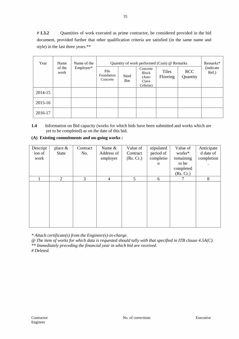
35
Contractor No. of corrections Executive
Engineer
# 1.3.2 Quantities of work executed as prime contractor, be considered provided in the bid
document, provided further that other qualification criteria are satisfied (in the same name and
style) in the last three years.**
Year
Name
of the
work
Name of the
Employer*
Quantity of work performed (Cum) @ Remarks
Remarks*
(indicate
Ref.) Pile
Foundation
Concrete
Steel
Bar
Concrete
Block
(Auto
Clave
Cellular)
Tiles
Flooring
RCC
Quantity
2014-15
2015-16
2016-17
1.4 Information on Bid capacity (works for which bids have been submitted and works which are
yet to be completed) as on the date of this bid.
(A) Existing commitments and on-going works :
Descript
ion of
work
place &
State
Contract
No.
Name &
Address of
employer
Value of
Contract
(Rs. Cr.)
stipulated
period of
completio
n
Value of
works*
remaining
to be
completed
(Rs. Cr.)
Anticipate
d date of
completion
.
1 2 3 4 5 6 7 8
* Attach certificate(s) from the Engineer(s)-in-charge.
@ The item of works for which data is requested should tally with that specified in ITB clause 4.5A(C).
** Immediately preceding the financial year in which bid are received.
# Deleted.
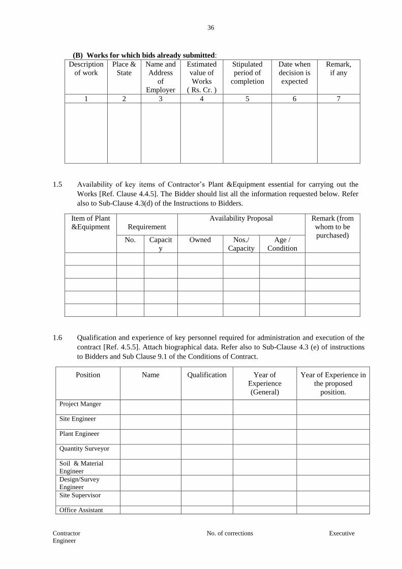
36
Contractor No. of corrections Executive
Engineer
(B) Works for which bids already submitted:
Description
of work
Place &
State
Name and
Address
of
Employer
Estimated
value of
Works
( Rs. Cr. )
Stipulated
period of
completion
Date when
decision is
expected
Remark,
if any
1 2 3 4 5 6 7
1.5 Availability of key items of Contractor’s Plant &Equipment essential for carrying out the
Works [Ref. Clause 4.4.5]. The Bidder should list all the information requested below. Refer
also to Sub-Clause 4.3(d) of the Instructions to Bidders.
Item of Plant
&Equipment
Requirement
Availability Proposal Remark (from
whom to be
purchased) No. Capacit
y
Owned Nos./
Capacity
Age /
Condition
1.6 Qualification and experience of key personnel required for administration and execution of the
contract [Ref. 4.5.5]. Attach biographical data. Refer also to Sub-Clause 4.3 (e) of instructions
to Bidders and Sub Clause 9.1 of the Conditions of Contract.
Position Name Qualification Year of
Experience
(General)
Year of Experience in
the proposed
position.
Project Manger
Site Engineer
Plant Engineer
Quantity Surveyor
Soil & Material
Engineer
Design/Survey
Engineer
Site Supervisor
Office Assistant
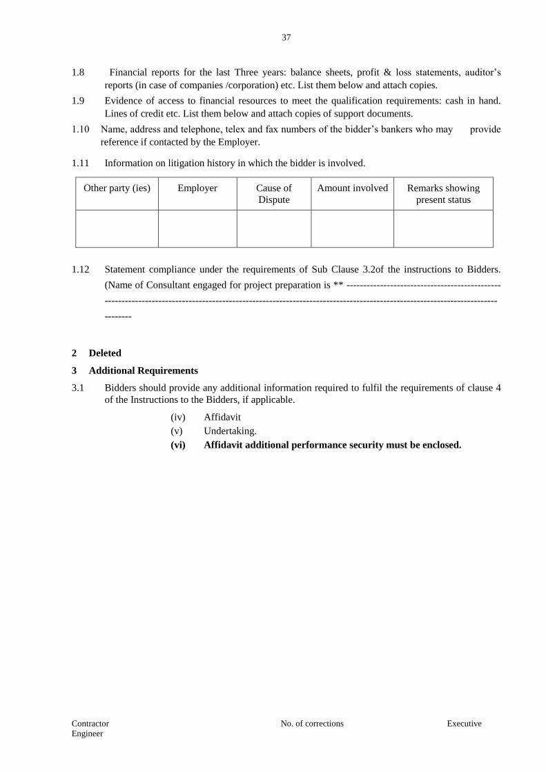
37
Contractor No. of corrections Executive
Engineer
1.8 Financial reports for the last Three years: balance sheets, profit & loss statements, auditor’s
reports (in case of companies /corporation) etc. List them below and attach copies.
1.9 Evidence of access to financial resources to meet the qualification requirements: cash in hand.
Lines of credit etc. List them below and attach copies of support documents.
1.10 Name, address and telephone, telex and fax numbers of the bidder’s bankers who may provide
reference if contacted by the Employer.
1.11 Information on litigation history in which the bidder is involved.
Other party (ies) Employer Cause of
Dispute
Amount involved Remarks showing
present status
1.12 Statement compliance under the requirements of Sub Clause 3.2of the instructions to Bidders.
(Name of Consultant engaged for project preparation is ** ----------------------------------------------
---------------------------------------------------------------------------------------------------------------------
--------
2 Deleted
3 Additional Requirements
3.1 Bidders should provide any additional information required to fulfil the requirements of clause 4
of the Instructions to the Bidders, if applicable.
(iv) Affidavit
(v) Undertaking.
(vi) Affidavit additional performance security must be enclosed.
38
Contractor No. of corrections Executive
Engineer
AFFIDAVIT
1. I, the undersigned, do hereby certify that all the statements made in the required attachments
are true and correct.
2. The undersigned also hereby certifies that neither our firm M/s. ____________
___________________________ have not abandoned any work on Maharashtra Maritime
Board / Public Work Department nor any contract awarded to us for such works have not
been rescinded, during last five years prior to the date of this bid.
3. The undersigned hereby authorise(s) and request(s) any bank, person, firm or corporation to
furnish pertinent information deemed necessary and requested by the Department to verify
this statement or regarding my (our) competence and general reputation.
4. The undersigned understand and agrees that further qualifying information may be requested
and agrees to furnish any such information at the request of the Department / Project
implementing agency.
_________________(Signed by Authorised Officer of the
Firm)
___________________
Name Title of Officer
____________________
Name of Firm
______________
DATE

39
Contractor No. of corrections Executive
Engineer
UNDERTAKING
I, the undersigned, do hereby undertake that our firm M/s.
__________________________________ would invest minimum cash up to 25 % of the value of
work during implementation of the Contract.
__________________
(Signed by Authorised Officer of the Firm)
___________________
Name Title of Officer
____________________
Name of Firm
______________
DATE

40
Contractor No. of corrections Executive
Engineer
SECTION – 3
CONDITIONS OF CONTRACT
41
Contractor No. of corrections Executive
Engineer
CONDITIONS OF CONTRACT
A.GENERAL
1. Definitions
1.1 Terms which are defined in the Contract Data are not also defined in the Conditions of Contract
but keep their defined meanings. Capital initial are used to identify defined terms.
The Adjudicator (Synonymous with Dispute Review Expert) is the person appointed jointly by
the Contractor to resolve disputes in the first instance, as provided for in clauses 24. The name of
the Adjudicator is defined in the Contract Data.
Bill of Quantities means the priced and completed Bill of Quantities forming part of the Bid.
Compensation Events are those defined in Clause 44 hereunder.
The Completion Date is the date of completion of the Works as certified by the Engineer in
accordance with Sub Clause 55.1.
The Contract is the contract between the Employer and the Contractor to execute, complete and
maintain the works. It consists of the documents listed in Clause 2.3 below.
The Contract Data defines the documents and other information which comprise the Contract.
The Contractor is a person or corporate body whose Bid to carry out the Works has been
accepted by the Employer.
The Contractor's Bid is the completed Bidding document submitted by the Contractor to the
Employer and includes Technical and Financial bids.
The Contract Price is the price stated in the Letter of Acceptance and thereafter as adjusted in
accordance with the provisions of the Contract.
Day are calendar days; months are calendar months.
A Defect is any part of the Works not completed in accordance with the Contract.
A Defects Liability Period is the period named in the Contract Data and calculated from the
Completion Date.
The Employer is the party who will employ the Contractor to carry out the Works.
The Engineer is the person named in the Contract Data (or any other competent person appointed
and notified to the contractor to act in replacement of the Engineer) who is responsible for
supervising the Contractor, administering the Contract, certifying payments due to the Contractor,
issuing the valuing Variations to the Contract, awarding extensions of time and valuing the
Compensation Events.
Equipment is the Contractor's machinery and vehicles brought temporarily to the Site to
construct the Works.
The Initial Contract Price is the Contract Price listed in the Employer's Letter of Acceptance.

42
Contractor No. of corrections Executive
Engineer
The Intended Completion Date is the date on which it is intended that the Contractor shall
complete the Works. The Intended Completion Date is specified in the Contract Data. The
intended Completion Date may be revised only by the Engineer by issuing an extension of time.
Materials are all supplies, including consumables, used by the contractor for incorporation in the
Works.
Plant is any integral part of the Works which is to have a mechanical, electrical, electronic or
chemical or biological function.
The Site is the area defined as such in the Contract Data.
Site Investigation Reports are those which were included in the Bidding documents and are
factual interpretative reports about the surface and sub-surface conditions at the site.
Specification means the Specification of the Works included in the Contract and any
modification or addition made or approved by the Engineer.
The Start Date is given in the Contract Data. It is the date when the Contractor shall commence
execution of the Works. It does not necessarily coincide with any of the Site Possession Dates.
A Subcontractor is a person or corporate body who has a Contract with the Contractor to carry
out a part of the work in the Contract which includes work on the Site.
Temporary Works are works designed, constructed, installed and removed by the Contractor
which are needed for construction or installation of the Works.
A variation is an instruction given by the Engineer, which varies the Works.
The Works are what the Contract requires the Contractor to construct, install and turn over to the
Employer, as defined in the Contract Data.
2. Interpretation
2.1 In interpreting these Conditions of Contract, singular also means plural, male also means female
or neuter, and the other way around. Headings have no significance. Words have their normal
meaning under the language of the Contract unless specifically defined. The Engineer will
provide instructions clarifying queries about the Conditions of Contract.
2.2 If sectional completion is specified in the Contract Data, references in the Conditions of Contract
to the Works, the Completion Date, and the Intended Completion Date apply to any Section of
the Works (other than references to the Completion Date and Intended Completion date for the
whole of the Works)
2.3 The documents forming the Contract shall be interpreted in the following order of priority:
(1) Agreement
(2) Letter of Acceptance, notice to proceed with the works.
(3) Contractor's Bid
(4) Contract Data
(5) Conditions of Contract including Special Conditions of Contract
(6) Specifications
(7) Drawings
(8) Bill of Quantities and
(9) Any other document listed in the Contract Data as forming part of Contract.

43
Contractor No. of corrections Executive
Engineer
3. Language and Law
3.1 The language of the Contract and the law governing the Contract are stated in the Contract Data
4. Engineer's Decisions
4.1 Except where otherwise specifically stated, the Engineer will decide contractual matters between
the Employer and the Contractor in the role representing the Employer.
5. Delegation
5.1 The Engineer may delegate any of his duties and responsibilities to other people except to the
Adjudicator after notifying the Contractor and may cancel any delegation after notifying the
Contractor.
6. Communications
6.1 Communications between parties which are referred to in the conditions are effective only when
in writing. A notice shall be effective only when it is delivered (in terms of India Contract Act).
7. Sub-Contracting - DELETED
8. Other Contractors
8.1 The Contractor shall co-operate and share the Site with other contractors, public authorities,
utilities and the Employer between the dates given in the Schedule of other Contractors. The
Contractor shall as referred to in Contract Data; also provide facilities and services for them as
described in the Schedule. The employer may modify the schedule of other contractors and shall
notify the contractor of any such modification.
9. Personnel
9.1 The Contractor shall employ the key personnel named in the Schedule of Key Personnel as
referred to in the Contract Data to carry out the functions stated in the Schedule or other
personnel approved by the Engineer. The Engineer will approve any proposed replacement of key
personnel only if their qualifications, abilities and relevant experience are substantially equal to or
better than those of the personnel listed in the Schedule.
9.2 If the Engineer asks the Contractor to remove a person who is a member of the Contractor's staff
or his work force stating the reasons the Contractor shall ensure that the person leaves the Site
within seven days and has no further connection with the work in the Contract.
10. Employer's and Contractor's Risks
10.1 The Employer carries the risks which this Contract states are Employer's risks, and the Contractor
carries the risks, which this Contract states are Contractor's risks.
11. Employer's Risks
11.1 The Employer is responsible for the excepted risks which are (a) in so far as they directly affect
the execution of the Works in India, the risks of war, hostilities, invasion, act of foreign enemies,
rebellion, revolution, insurrection or military or usurped power, civil war, riot commotion or
disorder (unless restricted to the Contractor's employees), and contamination from any nuclear
44
Contractor No. of corrections Executive
Engineer
fuel or nuclear waste or radioactive toxic explosive, or(b) a cause due solely to the design of the
Works, other than the Contractor's design.
12. Contractor's Risks
12.1 All risks of loss of or damage to physical property and of personal injury and death which arise
during and in consequence of the performance of the Contract other than the excepted risks are
the responsibility of the Contractor.
13. Insurance
13.1 The Contractor shall provide, in the joint names of the Employer and the Contractor, insurance
cover from the Start Date to the end of the Defects Liability Period, in the amounts and
deductibles stated in the Contract Data for the following events which are due to the Contractor's
risks.
(a) Loss of or damage to the Works. Plant and Materials:
(b) Loss of or damage to Equipment:
(c) Loss of or damage of property (except the Works, Plant, Materials and Equipment)
in connection with the Contract; and
(d) Personal injury or death.
13.2 (Contractor shall take out necessary Insurance Policy / Policies (viz. Contractors' All Risks
Insurance Policy, Erection All Risks Insurance Policy etc. as decided by the Directorate of
Insurance) so as to provide adequate insurance cover for execution of the awarded contract work
for total contract value and complete contract period compulsorily from the "Directorate of
Insurance, Maharashtra State, Mumbai" only, Its postal address for correspondence is "264,
MHADA, First floor, Opp. Kalanagar, Bandra (E), Mumbai-400051". (Telephone
Number26590403 / 26590690 and Fax Number 26592461 / 26590403). Similarly all workmen's
appointed to complete the contract work are required to insure under workmen's compensation
Insurance Policy, Insurance Policy / Policies taken out from any Insurance Company, the same
will not be accepted and the amount of premium calculated by the Government Insurance Fund
will be recovered directly from the amount payable to the contractor for the executed contract
work and paid to the Directorate of Insurance Fund, Maharashtra State, Mumbai. The Director
of Insurance reserves the right to distribute the risks of insurance among the other insurers. (As
per revised circulate issued by Dy. Directorate of Insurance Maharashtra State vide letter No.
|ÉÉÊ´ÉÊxÉ-2310/ºÉÉ.¤ÉÉÆ.Ê´É/ʴɨÉÉ.´ÉºÉÖ±ÉÒ/+ʦÉ-3/ dated 8.9.2010 below mentioned percentage for
insurance of contract work shall be added in the recapitulation sheet while framing the estimate
as it is not considered in the D.S.R. while arriving at rates and the amount incurred by
contractors for insurance of work shall be reimbursed on production of documentary evidence
and after checking
a) Work value upto Rs. 25.00 lakhs - 0.50% b) Work value above Rs. 25.00 lakhs =
1.00%.)
13.3 Policies and certificates for insurance shall be delivered by the Contractor to the Engineer for the
Engineer's approval before the Start Date. All such insurance shall provide for compensation to
be payable in the types and proportions of currencies required to rectify the loss or damage
incurred.
13.4 If the Contractor does not provide any of the policies and certificates required, the Employer may
affect the insurance which the Contractor should have provided and recover the premiums the
45
Contractor No. of corrections Executive
Engineer
Employer has paid from payments otherwise due to the Contractor or, if no payment is due, the
payment of the premiums shall be a debt due.
13.5 Alterations to the terms of insurance shall not be made without the approval of the Engineer.
13.6 Both parties shall comply with any conditions of the insurance policies.
13.7 CESS ON BUILDING & CONSTRUCTION LABOUR WELFARE
An amount of equal to one percent on amount of tendered amount shall be deducted from the payment of
contractor as a cess on building & construction labour welfare. The deducted amount shall be remitted in
to account number 00422010000153 in the Bank of India of Chairman, Maharashtra Building & Other
construction labour welfare circle, Mumbai.
14. Site Investigation reports
14.1 The contractor, in preparing the Bid, shall rely on any Site Investigation Reports referred to in the
Contract Data, supplemented by any information available to the Bidder.
15. Queries about the Contract Data
15.1 The Engineer will clarify queries on the Contract Data.
16. Contractor to Construct the Works
16.1 The Contractor shall construct and install the Works in accordance with the Specification and
Drawings.
17. The Works to be completed by the Intended Completion Date
17.1 The Contractor may commence execution of the Works on the Start Date and shall carry out the
Works in accordance with the programme submitted by the contractor, as updated with the
approval of the Engineer, and complete them by the Intended Completion Date.
18. Approval by the Engineer
18.1 The Contractor shall submit Specifications and Drawings showing the proposed Temporary
Works to the Engineer, who is to approve them if they comply with the Specifications and
Drawings.
18.2 The Contractor shall be responsible for design of Temporary Works.
18.3 The Engineer's approval shall not alter the Contractor's responsibility for design of the Temporary
Works.
18.3 The Contractor shall obtain approval of third parties to the design of the Temporary Works where
required.
18.5 All Drawings prepared by the Contractor for the execution of the temporary or permanent Works,
are subject to prior approval by the Engineer before their use.
19. Safety
19.1 The Contractor shall be responsible for the safety of all activities on the Site.
20. Discoveries
46
Contractor No. of corrections Executive
Engineer
20.1 Anything of historical or other interest or of significant value unexpectedly discovered on the Site
is the property of the Employer. The Contractor is to notify the Engineer of such discoveries and
carry out the Engineer's instructions for dealing with them.
21. Possession of the Site
21.1 The Employer shall give possession of all parts of the Site to the Contractor. If possession of a
part is not given by the date stated in the Contract Data the Employer is deemed to have delayed
the start of the relevant activities.
22. Access to the Site
22.1 The Contractor shall allow the Engineer and any person authorized by the Engineer access to the
Site, to any place where work in connection with the Contract is being carried out or is intended
to be carried out and to any place where materials or plant are being
manufactured/fabricated/assembled for the works.
23. Instructions
23.1 The contractor shall carry out all instructions of the Engineer pertaining to works which comply
with the applicable laws where the Site is located.
23.2 The Contractor shall permit the Employer to inspect the Contractor's accounts and records
relating to the performance of the Contractor and to have them audited by auditors appointed by
the Employer, if so required by the Employer.
24. Disputes
DELETED
25. Procedure for Disputes
DELETED
26. Replacement of Dispute Review Expert
DELETED

47
Contractor No. of corrections Executive
Engineer
B. TIME CONTROL
27. Programme
27.1 Within the time stated in the Contract Data the Contractor shall submit to the Engineer for
approval a Programme showing the general methods, arrangements, order and timing for all the
activities in the Works along with monthly cash flow forecast.
27.2 An update of the Programme shall be a Programme showing the actual progress achieved on each
activity and the effect of the progress achieved on the timing of the remaining work including any
changes to the sequence of the activities.
27.3 The contractor shall submit to the Engineer, for approval, an updated Programme at intervals no
longer than the period stated in the Contract Data. If the Contractor does not submit an updated
Programme within this period, the Engineer may withhold the amount stated in the Contract Data
from the next payment certificate and continue to withhold this amount until the next payment
after the date on which the overdue Programme has been submitted.
27.4 The Engineer's approval of the Programme shall not alter the Contractor's obligations. The
Contractor may revise the Programme and submit it to the Engineer again at any time. A revised
Programme is to show the effect of Variations and Compensation Events.
* Dispute Review Expert to be provided for works costing up to Rs. 50 Crores. Dispute Review
Board of three members (One from Employer, One from Contractor and One to be nominated by
IRC Council and agreed by the representative members of Employer and Contractor) for works
costing more than Rs. 50 crores.
28. Extension of the Intended Completion Date
28.1 The Engineer shall extend the Intended Completion Date if a Compensation Event occurs or a
Variation is issued which makes it impossible for Completion to be achieved by the Intended
Completion Date without the Contractor taking steps to accelerate the remaining work and which
would cause the Contractor to incur additional cost.
28.2 The Engineer shall decide whether and by how much to extend the Intended Completion Date
within 35 days of the Contractor asking the Engineer for a decision upon the effect of a
Compensation Event or Variation and submitting full supporting information. If the Contractor
has failed to give early warning of a delay or has failed to co-operate in dealing with a delay, the
delay by this failure shall not be considered in assessing the new Intended Completion Date.
28.3 The Engineer shall within 14 days of receiving full justification from the contractor for extension
of Intended Completion Date refer to the Employer his decision. The Employer shall in not more
than 21 days communicate to the Engineer the acceptance or otherwise of the Engineer's decision.
If the Employer fails to give his acceptance, the Engineer shall not grant the extension and the
contractor may refer the matter to the Dispute Review Expert under Clause 24.1
29. Deleted
30. Delays Ordered by the Engineer
30.1 The Engineer may instruct the Contractor to delay the start or progress of any activity within the
Works.

48
Contractor No. of corrections Executive
Engineer
31. Management Meetings
31.1 Either the Engineer or the Contractor may require the other to attend a management meeting. The
business of a management meeting shall be to review the plans for remaining work and to deal
with matters raised in accordance with the early warning procedure.
31.2 The Engineer shall record the business of management meetings and is to provide copies of his
record to those attending the meeting and to the Employer. The responsibility of the parties for
actions to be taken is to be decided by the Engineer either at the management meeting or after the
management meeting and stated in writing to al who attended the meeting.
32. Early Warning
32.1 The Contractor is to warn the Engineer at the earliest opportunity of specific likely future events
or circumstances that may adversely affect the quality of the work, increase the Contract Price or
delay the execution of works. The Engineer may require the Contractor to provide an estimate of
the expected effect of the future event or circumstance on the Contract Price and Completion
Date. The estimate is to be provided by the Contractor as soon as reasonably possible.
32.2 The Contractor shall co-operate with the Engineer in making and considering proposals for how
the effect of such an event or circumstance can be avoided or reduced by anyone involved in the
work and in carrying out any resulting instruction of the Engineer.

49
Contractor No. of corrections Executive
Engineer
C. QUALITY CONTROL
33. Identifying Defects
33.1 The Engineer shall check the Contractor's work and notify the Contractor of any Defects that are
found. Such checking neither shall not affect the Contractor's responsibilities. The Engineer may
instruct the Contractor to search for a Defect and to uncover and test any work that the Engineer
considers may have a Defect.
34. Tests
34.1 If the Engineer instructs the Contractor to carry out a test not specified in the Specification to
check whether any work has a Defect and the test shows that it does, the Contractor shall pay for
the test and any samples. If there is no Defect the test shall be a Compensation Event.
35. Correction of Defects
35.1 The Engineer shall give notice to the Contractor of any Defects before the end of the Defects
Liability Period, which begins at Completion and is defined in the Contract Data. The Defects
Liability Period shall be extended for as long as Defects remain to be corrected.
35.2 Every time notice of a Defect is given, the Contractor shall correct the notified Defect within the
length of time specified by the Engineer's notice.
36. Uncorrected Defects
36.1 If the Contractor has not corrected a Defect within the time specified in the Engineer's notice, the
Engineer will assess the cost of having the Defect corrected, and the Contractor will pay this
amount.

50
Contractor No. of corrections Executive
Engineer
D. COST CONTROL
37. Bill of Quantities
37.1 The Bill of Quantities shall contain items for the construction, installation, testing and
commissioning work to be done by the Contractor.
37.2 The Bill of Quantities is used to calculate the Contract Price. The Contractor is paid for the
quantity of the work done at the rate in the Bill of Quantities for each item.
38. Changes in the Quantities
38.1 If the final quantity of the work done differs from the quantity in the Bill of Quantities for the
particular item by more than 25 percent provided the change exceeds 1% of initial Contract Price,
the Engineer shall adjust the rate to allow for the change, duly considering.
(a) Justification for rate adjustment as furnished by the contractor.
(b) Economics resulting from increase in quantities by way of reduced plant,
equipment and overhead costs.
(c) Entitlement of the contractor to compensation events where such events are caused by
any additional work.
38.2 The Engineer shall not adjust rates from changes in quantities if thereby the Initial Contract Price
is
exceeded by more than 15 percent, except with the Prior approval of the Employer.
38.3 If requested by the Engineer, the Contractor shall provide the Engineer with a detailed cost
breakdown of any rate in the Bill of Quantities.
39. Variations
39.1 All Variations shall be included in updated Programmers produced by the Contractor.
40. Payments for Variations
40.1 The Contractor shall provide the Engineer with a quotation (with breakdown of unit rates) for
carrying out the Variation when requested to do so by the Engineer. The Engineer shall assess the
quotation, which shall be given within seven days of the request or within any longer period
stated by the Engineer and before the variation is ordered.
40.2 If the work in the Variation corresponds with an item description in the Bill of Quantities and if,
in the opinion of the Engineer, the quantity of work above the limit stated in Sub Clause 38.1 or
the timing of its execution do not cause the cost per unit of quantity to change, the rate in the Bill
of Quantities shall be used to calculate the value of the Variation. If the cost per unit of quantity
changes, or if the nature or timing of the work in the Variation does not correspond with items in
the Bill of Quantities, the quotation by the Contractor shall be in the form of new rates for the
relevant items of work.
40.3 If the Contractor's quotation is unreasonable, the Engineer may order the Variations and make a
change to the Contract Price which shall be based on Engineer's own forecast of the effects of the
Variation on the Contractor's costs.
51
Contractor No. of corrections Executive
Engineer
40.4 If the Engineer decides that the urgency of varying the work would prevent a quotation being
given and considered without delaying the work, no quotation shall be given and the Variation
shall be treated as a Compensation Event.
40.5 The Contractor shall not be entitled to additional payment for costs which could have been
avoided by giving early warning.
41. Cash Flow Forecasts
41.1 When the Programme is updated, the contractor is to provide the Engineer with an updated cash
flow forecast.
42. Payment Certificates
42.1 The Contractor shall submit to the Engineer monthly statements of the estimate value of the work
completed less the cumulative amount certified previously.
42.2 The Engineer shall check the Contractor's monthly statement within 14 days and certify the
amount to be paid to the Contractor after taking into account any credit or debit for the month in
question in respect of materials for the works in the relevant amounts and under conditions set
forth in sub-clause 51(3) of the Contract Data (Secured Advance)
42.3 The value of work executed shall be determined by the Engineer.
42.4 The value of work executed shall comprise the value of the quantities of the items in the Bill of
Quantities completed.
42.5 The value of work executed shall include the valuation of Variations and Compensation Events.
42.6 The Engineer may exclude any item certified in a previous certificate or reduce the proportion of
any item previously certified in any certificate in the light of later information.
43. Payments
43.1 Payments shall be adjusted for deductions for other recoveries in terms of the contract and taxes
at source, as applicable under the law. Contractors the amount certified by Engineer as per
availability of funds and no interest shall be payable in case of any delayed payment.
43.2 If an amount certified is increased in a later certificate as a result of an award by the Adjudicator
or an Arbitrator, the Contractor shall be paid interest upon the delayed payment as set out in this
clause. Interest shall be calculated from the date upon which the increased amount would have
been certified in the absence of dispute.
43.3 Items of the Works for which no rate or price has been entered in will not be paid for by the
Employer and shall be deemed covered by other rates and prices in the Contract.
44. Compensation Events
44.1 The following are Compensation Events unless they are caused by the Contractor.
(a) The Employer does not give access to a part of the Site by the Site Possession Date stated
in the Contract Data.
(b) The Employer modifies the schedule of other contractors in a way which affects the work
of the contractor under the contract.
52
Contractor No. of corrections Executive
Engineer
(c) The Engineer orders a delay or does not issue drawings, specifications or instructions
required for execution of works on time.
(d) The Engineer instructs the Contractor to uncover or to carry out additional tests upon
work which is then found to have no Defects.
(e) The Engineer does not approve of a sub contract to be let, within 15 days.
(f) Ground conditions are substantially more adverse than could reasonably have been
assumed before issuance of Letter of Acceptance from the information issued to Bidders
(including the Site Investigation Reports), from information available publicly and from a
visual inspection of the site.
(g) The Engineer gives an instruction for dealing with an unforeseen condition, cause by the
Employer, or additional work required for safety or other reasons.
(h) Other contractors, public authorities, utilities or the Employer does not work within the
dates and other constraints stated in the Contract, and they cause delay or extra cost to the
Contractor.
(i) The advance payment is delayed, beyond 28 days after receipt of application and bank
guarantee.
(j) The effect on the Contractor of any of the Employer's Risks.
(k) The Engineer unreasonably delays issuing a Certificate of Completion.
(l) Other Compensation Events listed in the Contract Data or mentioned in the Contract.
44.2 If a Compensation Event would cause additional cost or would prevent the work being completed
before the Intended Completion Date, the Contract Price shall be increased and/or the Intended
Completion Date is extended. The Engineer shall decide whether and by how much the Contract
Price shall be increased and whether and by how much the Intended Completion Date shall be
extended.
44.3 As soon as information demonstrating the effect of each Compensation Event upon the
Contractor's forecast cost has been provided by the Contractor, it is to be assessed by the
Engineer and the Contract Price shall be adjusted accordingly. If the contractors forecast deemed
unreasonable, the Engineer shall adjust the Contract Price based on Engineer's own forecast. The
Engineer will assume that the Contractor will react competently and promptly to the event.
44.4 The Contractor shall not be entitled to compensation to the extent that the Employer's interests
are adversely affected by the Contractor not having given early warning or not having co-
operated with the Engineer.
45. Tax
45.1 The rates quoted by the Contractor shall be deemed to be inclusive of the sales and other taxes
that the Contractor will have to pay for performance of this Contract. The Employer will perform
such duties in regard to the deduction of such taxes at source as per applicable law.
46. Currencies
46.1 All payments shall be made in Indian Rupees.
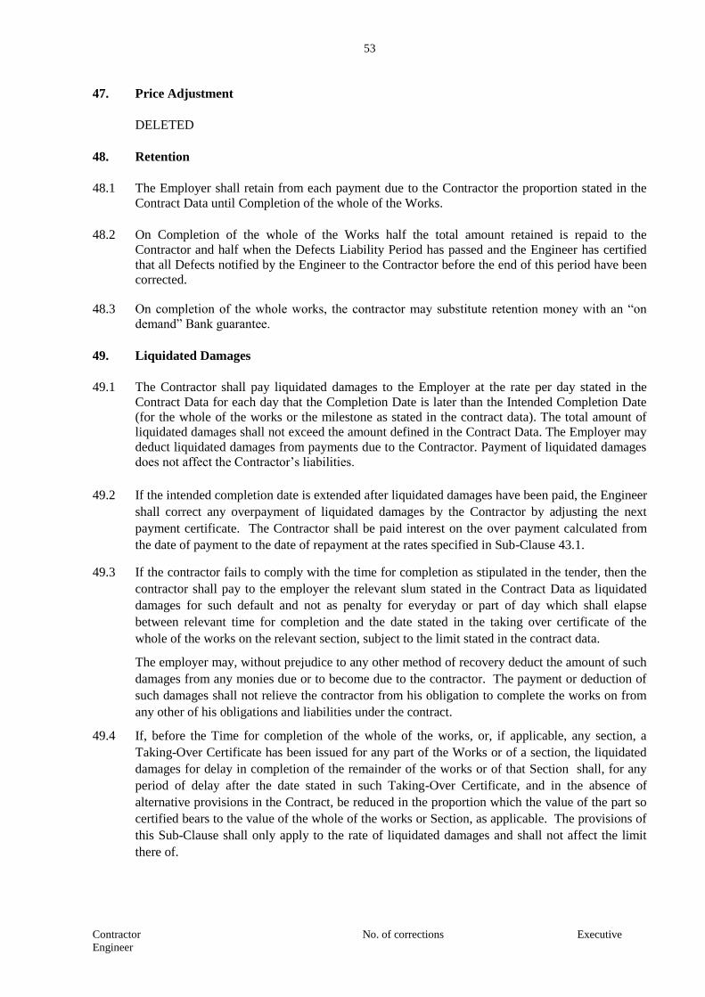
53
Contractor No. of corrections Executive
Engineer
47. Price Adjustment
DELETED
48. Retention
48.1 The Employer shall retain from each payment due to the Contractor the proportion stated in the
Contract Data until Completion of the whole of the Works.
48.2 On Completion of the whole of the Works half the total amount retained is repaid to the
Contractor and half when the Defects Liability Period has passed and the Engineer has certified
that all Defects notified by the Engineer to the Contractor before the end of this period have been
corrected.
48.3 On completion of the whole works, the contractor may substitute retention money with an “on
demand” Bank guarantee.
49. Liquidated Damages
49.1 The Contractor shall pay liquidated damages to the Employer at the rate per day stated in the
Contract Data for each day that the Completion Date is later than the Intended Completion Date
(for the whole of the works or the milestone as stated in the contract data). The total amount of
liquidated damages shall not exceed the amount defined in the Contract Data. The Employer may
deduct liquidated damages from payments due to the Contractor. Payment of liquidated damages
does not affect the Contractor’s liabilities.
49.2 If the intended completion date is extended after liquidated damages have been paid, the Engineer
shall correct any overpayment of liquidated damages by the Contractor by adjusting the next
payment certificate. The Contractor shall be paid interest on the over payment calculated from
the date of payment to the date of repayment at the rates specified in Sub-Clause 43.1.
49.3 If the contractor fails to comply with the time for completion as stipulated in the tender, then the
contractor shall pay to the employer the relevant slum stated in the Contract Data as liquidated
damages for such default and not as penalty for everyday or part of day which shall elapse
between relevant time for completion and the date stated in the taking over certificate of the
whole of the works on the relevant section, subject to the limit stated in the contract data.
The employer may, without prejudice to any other method of recovery deduct the amount of such
damages from any monies due or to become due to the contractor. The payment or deduction of
such damages shall not relieve the contractor from his obligation to complete the works on from
any other of his obligations and liabilities under the contract.
49.4 If, before the Time for completion of the whole of the works, or, if applicable, any section, a
Taking-Over Certificate has been issued for any part of the Works or of a section, the liquidated
damages for delay in completion of the remainder of the works or of that Section shall, for any
period of delay after the date stated in such Taking-Over Certificate, and in the absence of
alternative provisions in the Contract, be reduced in the proportion which the value of the part so
certified bears to the value of the whole of the works or Section, as applicable. The provisions of
this Sub-Clause shall only apply to the rate of liquidated damages and shall not affect the limit
there of.

54
Contractor No. of corrections Executive
Engineer
50. Bonus -
DELETED
51. Advance Payment -
DELETED
52. Securities
52.1 The Performance Security (including additional security for unbalanced bids) shall be provided to
the Employer no later than the date specified in the Letter of Acceptance and shall be issued in an
amount and form and by a bank or surety acceptable to the Employer and denominated in Indian
Rupees. The Performance Security shall be valid until a date 28 days from the date of expiry of
Defects Liability Period and the additional security for unbalanced bids shall be valid until a date
28 days from the date of issue of the certificate of completion.
53. Deleted
54. Cost of Repairs
54.1 Loss or damage to the Works or Materials to be incorporated in the Works between the Start Date
and the end of the Defects Correction periods shall be remedied by the contractor at the
Contractor’s cost if the loss or damage arises from the contractor’s acts or omissions.

55
Contractor No. of corrections Executive
Engineer
E. FINISHING THE CONTRACT
55. Completion
55.1 The Contractor shall request the Engineer to issue a Certificate of Completion of the works and
the Engineer will do so upon deciding that the work is completed.
56. Taking Over
56.1 The Employer shall take over the Site and the Works within seven days of the Engineer issuing a
certificate of Completion.
57. Final Account
57.1 The Contractor shall supply to the Engineer a detailed account of the total amount that the
Contractor considers payable under the Contract before the end of the Defects Liability Period.
The Engineer shall issue a Defect Liability Certificate and certify any final payment that is due to
the Contractor within 56 days of receiving the Contractor’s account if it is correct and complete.
If it is not, the Engineer shall issue within 56 days a schedule that states the scope of the
corrections or additions that are necessary. If the Final Account is still unsatisfactory after it has
been resubmitted, the Engineer shall decide on the amount payable to the Contractor and issue a
payment certificate, within 56 days of receiving the Contractor’s revised account.
58. Operating and Maintenance Manuals
58.1 If ”as built” Drawings and/or operating and maintenance manuals are required, the Contractor
shall supply them by the dates stated in the Contract Data.
58.2 If the Contractor does not supply the Drawings and/or Manuals by the dates stated in the Contract
Data, or they do not receive the Engineer’s approval, the Engineer shall withhold the amount
stated in the Contract Data from payments due to the Contractor.
59. Termination
59.1 The Employer or the Contractor may terminate the Contract if the other party causes a
fundamental breach of the Contract.
59.2 Fundamental breaches of Contract include, but shall not be limited to the following
(a) The contractor stops work for 28 days when no stoppage of work is shown on the current
Programme and the stoppage has not been authorized by the Engineer.
(b) The Engineer instructs the Contractor to delay the progress of the Works and the
instruction is not withdrawn within 28 days.
(c) The Employer or contractor is made bankrupt or goes into liquidation other than for a
reconstruction or amalgamation;
(d) A payment certified by the Engineer is not paid by the Employer to the Contractor within
56 days of the date of the Engineer’s Certificate.
(e) The Engineer gives Notice that failure to correct particular Defect is a fundamental breach
of Contract and the Contractor fails to correct it within a reasonable period of time
determined by the Engineer.

56
Contractor No. of corrections Executive
Engineer
(f) The Contractor does not maintain a security, which is required.
(g) The Contractor has delayed the completion of works by the number of days for which
the maximum amount of liquidated damages can be paid as defined in the Contract Data;
and
(h) If the Contractor in the judgment of the Employer has engaged in corrupt or fraudulent
practices in competing for or in executing the Contract
For the purpose of this paragraph: “corrupt practice” means the offering, giving,
receiving or soliciting of anything of value to influence the action of a public official in the
procurement process or in contract executing. “Fraudulent Practice” means a misrepresentation of
facts in order to influence a procurement process or the execution of a contract to the detriment of
the Borrower, and includes collusive practice among Bidders (Prior to or after bid submission)
designed to establish bid prices at artificial non-competitive levels and to deprive the Borrower of
the benefits of free and open competition”.
59.3 When either party to the Contract gives notice of a breach of contract to the Engineer for a cause
other than those listed under Sub-Clause 59.2 above, the Engineer shall decide whether the
breach is fundamental or not.
59.4 Notwithstanding the above, the Employer may terminate the Contract for convenience.
59.5 If the Contract is terminated the Contractor shall stop work immediately, make the site safe and
secure and leave the site as soon as reasonably possible.
60. Payment upon Termination
60.1 If the Contract is terminated because of a fundamental breach of Contract by the Contractor, the
Engineer shall issue a certificate for the value of the work done less advance payments received
upon the date of the issue of the certificate, less other recoveries due in terms of the contract, less
taxes due to be deducted at source as per applicable law and less the percentage to apply to the
work not completed as indicated in the Contract Data. Additional Liquidated Damages shall not
apply. If the total amount due to the Employer exceeds any payment due to the Contractor the
difference shall be a debt payable to the Employer.
60.2 If the contract is terminated at the Employer’s convenience or because of a fundamental breach of
Contract by the Employer, the Engineer shall issue a Certificate for the value of the work done,
the cost of balance material brought by the contractor and available at site, the reasonable cost of
removal of Equipment, repatriation of the Contractor’s personnel employed solely on the Works,
and the Contractor’s Costs of protecting and securing the Works and less advance payments
received up to the date of the certificate, less other recoveries due in terms of the contract and less
taxes due to be deducted at source as per applicable law.
61. Property
61.1 All materials on the site, Plant, Equipments, Temporary Works and Works are deemed to be the
property of the Employer, if the Contract is terminated because of a Contractor’s default.
62. Releases from Performance
62.1 If the contractor is frustrated by the outbreak of war or by any other event entirely outside the
control of either the Employer or the Contractor the Engineer shall certify that the Contract has

57
Contractor No. of corrections Executive
Engineer
been frustrated. The Contractor shall make the site safe and stop work as quickly as possible
after receiving this certificate and shall be paid for all work carried out before receiving it and for
any work carried out afterwards to which commitment was made.

58
Contractor No. of corrections Executive
Engineer
F. SPECIAL CONDITIONS OF CONTRACT
1. LABOUR
The Contractor shall, unless otherwise provided in the Contract, make his own arrangements for
the engagement of all staff and labour, local or other, and for their payment housing, feeding and
transport. The Contractor shall, if required by the Engineer, deliver to the Engineer a return in
detail, in such form and at such intervals as the Engineer may prescribe, showing the staff and the
numbers of the several classes of labour from time to time employed by the Contractor on the site
and such other information as the Engineer may require.
2. COMPLIANCE WITH LABOUR REGULATIONS
During continuance of the contract, the Contractor and his sub-contractors shall abide at all times
bay all existing labour enactments and rules made there under, regulations, notifications and bye
laws of the state or Central Government or local authority and any other labour law (including
rules), regulations, bye laws that may be passed or notification that may be issued under any
labour law in future either by the State or the Central Government or the local authority. Salient
features of some of the major labour laws that are applicable to construction industry are given
below. The Contractor shall keep the Employer indemnified in case any action is taken against
the Employer by the competent authority on account of contravention of any of the provisions of
any Act or rules made there under, regulations or notifications including amendments. If the
Employer is caused to pay or reimburse,, such amounts as may be necessary to cause or observe
or for non-observance of the provisions stipulated in the notifications/bye
laws/Acts/Rules/Regulations including amendments, if any, on the part of the Contractor, the
Engineer/Employer shall have the right to deduct any money due to the Contractor, including his
amount of performance security. The Employer / Engineer shall also have right to recover from
the Contractor any sum required or estimated to be required for making good the loss or damage
suffered by the Employer.
The employees of the Contractor and the Sub-Contractor in no case shall be treated as the
employees of the Employer at any point of time.
SALIENT FEATURES OF SOME MAJOR LABOUR LAWS APPLICABLE TO
ESTABLISHMENTS ENGAGED IN BUILDING AND OTHER CONSTRUCTION WORK.
a) Workmen Compensation Act 1923: - The Act provides for compensation in case of injury by
accident arising out of and during the course of employment.
b) Payment of Gratuity Act 1972: - Gratuity is payable to an employee under the Act on
satisfaction of certain conditions on separation if an employee has completed 5 years service or
more on death, the rate of 15 days wages for every completed year of service. The Act is
applicable to all establishments employing 10 or more employees.
c) Employees P.F. and Miscellaneous Provision Act 1952 :- The Act provides for monthly
contributions by the employer plus workers @ 10% or 8.33%. The benefits payable under the
Act are :
(i) Pension or family pension on retirement or death, as the case may be.
(ii) Deposit linked insurance on the death in harness of the worker.
(iii) Payment of P.F. accumulation on retirement/death etc.

59
Contractor No. of corrections Executive
Engineer
d) Maternity Benefit Act 1951 :- The Act provides for leave and some other benefits to Women
employees in case of confinement or miscarriage etc.
e) Contract Labour (Regulation & Abolition) Act 1970 :- The Act provides for certain welfare
measures to be provided by the Contractor to contract labour and in case the Contractor fails to
provide ,the same are required to be provided, by the principal Employer by law. The Principal
Employer is required to take Certificate of Registration and the Contractor is required to take
license from the designated Officer. The Act is applicable to the establishments or contractor of
Principal Employer, if they employ 20 or more contract labour.
f) Minimum Wages Act 1948 :- The Employer is supposed to pay not less than the Minimum
Wages fixed by appropriate Government as per provisions of the Act, if the employment is a
scheduled employment. Construction of buildings, Roads, Runways is scheduled employments.
g) Payment of Wages Act 1936 :- It lays down as to by what date the wages are to be paid when it
will be paid and what deductions can be made from the wages of the workers.
h) Equal Remuneration Act 1979: -The Act provides for payment of equal wages for work of
equal nature to male and female workers and for not making discrimination against Female
employees in the matters of transfers, training and promotions etc.
i) Payment of Bonus Act 1965:- The Act is applicable to all establishments employing 20 or more
employees. The Act provides for payments of annual bonus subject to a minimum of 8.33 % of
wages and maximum of 20% of wages to employees drawing Rs. 3500/- per month or less. The
bonus to be paid to employees getting Rs. 2500/- per month or above up to Rs.3500/- per month
shall be worked out by taking wages as Rs. 2500/- per month only. The Act does not apply to
certain establishments. The newly set-up establishments are exempted for five years in certain
circumstances. Some of the State Governments have reduced the employment size from 20 to 10
for the purpose of applicability of this Act.
j) Industrial Disputers Act 1947 :- The Act lays down the machinery and procedure for
resolution of Industrial disputes, in what situations a strike or lock-out becomes illegal and what
are the requirements for laying off or retrenching the employees or closing down the
establishment.
k) Industrial Employment (Standing Orders) Act 1946:- It is applicable to all establishments
employing 100 or more workmen (employment size reduced by some of the States and Central
Government to 50). The Act provides for laying down rules governing the conditions of
employment by the Employer on matters provided in the Act and get the same certified by the
designated Authority.
l) Trade Unions Act 1926 :- The Act lays down the procedure for registration of trade unions of
workmen and employers. The Trade Unions registered under the Act have been given certain
immunities from civil and criminal liabilities.
m) Child Labour :- Prohibition and Regulation) Act 1986 :- The Act prohibits employment of
children below 14 years of age in certain occupations and processes and provides for regulation
of employment of children in all other occupations and processes. Employment of Child Labour
is prohibited in Building and Construction Industry.
n) Inter-State Migrating Workmen’s (Regulation of Employment & Conditions of Service) Act
1979 :- The Act is applicable to an establishment which employees 5 or more Inter-State
migrant workmen through an intermediary (who has recruited workmen in one state for
employment in the establishment situated in another state). The Inter-State migrant workmen, in
an establishment to which this Act becomes applicable, are required to be provided certain
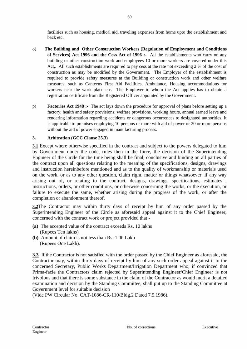
60
Contractor No. of corrections Executive
Engineer
facilities such as housing, medical aid, traveling expenses from home upto the establishment and
back etc.
o) The Building and Other Construction Workers (Regulation of Employment and Conditions
of Services) Act 1996 and the Cess Act of 1996 :- All the establishments who carry on any
building or other construction work and employees 10 or more workers are covered under this
Act,. All such establishments are required to pay cess at the rate not exceeding 2 % of the cost of
construction as may be modified by the Government. The Employer of the establishment is
required to provide safety measures at the Building or construction work and other welfare
measures, such as Canteens First Aid Facilities, Ambulance, Housing accommodations for
workers near the work place etc. The Employer to whom the Act applies has to obtain a
registration certificate from the Registered Officer appointed by the Government.
p) Factories Act 1948 :- The act lays down the procedure for approval of plans before setting up a
factory, health and safety provisions, welfare provisions, working hours, annual earned leave and
rendering information regarding accidents or dangerous occurrences to designated authorities. It
is applicable to premises employing 10 persons or more with aid of power or 20 or more persons
without the aid of power engaged in manufacturing process.
3. Arbitration (GCC Clause 25.3)
3.1 Except where otherwise specified in the contract and subject to the powers delegated to him
by Government under the code, rules then in the force, the decision of the Superintending
Engineer of the Circle for the time being shall be final, conclusive and binding on all parties of
the contract upon all questions relating to the meaning of the specifications, designs, drawings
and instruction hereinbefore mentioned and as to the quality of workmanship or materials used
on the work, or as to any other question, claim right, matter or things whatsoever, if any way
arising out of, or relating to the contract, designs, drawings, specifications, estimates ,
instructions, orders, or other conditions, or otherwise concerning the works, or the execution, or
failure to execute the same, whether arising during the progress of the work, or after the
completion or abandonment thereof.
3.2The Contractor may within thirty days of receipt by him of any order passed by the
Superintending Engineer of the Circle as aforesaid appeal against it to the Chief Engineer,
concerned with the contract work or project provided that -
(a) The accepted value of the contract exceeds Rs. 10 lakhs
(Rupees Ten lakhs)
(b) Amount of claim is not less than Rs. 1.00 Lakh
(Rupees One Lakh).
3.3 If the Contractor is not satisfied with the order passed by the Chief Engineer as aforesaid, the
Contractor may, within thirty days of receipt by him of any such order appeal against it to the
concerned Secretary, Public Works Department/Irrigation Department who, if convinced that
Prima-facie the Contractors claim rejected by Superintending Engineer/Chief Engineer is not
frivolous and that there is some substance in the claim of the Contractor as would merit a detailed
examination and decision by the Standing Committee, shall put up to the Standing Committee at
Government level for suitable decision
(Vide PW Circular No. CAT-1086-CR-110/Bldg.2 Dated 7.5.1986).
61
Contractor No. of corrections Executive
Engineer
SECTION – 4
CONTRACT DATA
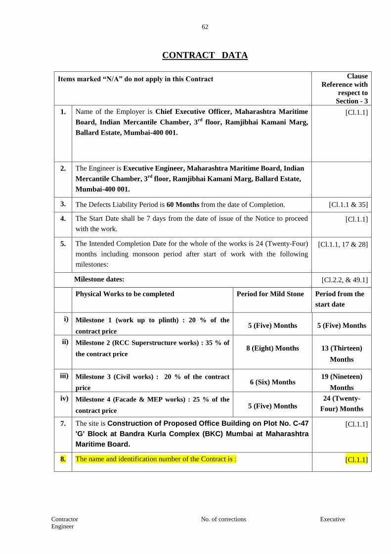
62
Contractor No. of corrections Executive
Engineer
CONTRACT DATA
Items marked “N/A” do not apply in this Contract Clause
Reference with
respect to
Section - 3
1. Name of the Employer is Chief Executive Officer, Maharashtra Maritime
Board, Indian Mercantile Chamber, 3rd
floor, Ramjibhai Kamani Marg,
Ballard Estate, Mumbai-400 001.
[Cl.1.1]
2. The Engineer is Executive Engineer, Maharashtra Maritime Board, Indian
Mercantile Chamber, 3rd
floor, Ramjibhai Kamani Marg, Ballard Estate,
Mumbai-400 001.
3. The Defects Liability Period is 60 Months from the date of Completion. [Cl.1.1 & 35]
4. The Start Date shall be 7 days from the date of issue of the Notice to proceed
with the work.
[Cl.1.1]
5. The Intended Completion Date for the whole of the works is 24 (Twenty-Four)
months including monsoon period after start of work with the following
milestones:
[Cl.1.1, 17 & 28]
Milestone dates: [Cl.2.2, & 49.1]
Physical Works to be completed Period for Mild Stone Period from the
start date
i) Milestone 1 (work up to plinth) : 20 % of the
contract price 5 (Five) Months 5 (Five) Months
ii) Milestone 2 (RCC Superstructure works) : 35 % of
the contract price
8 (Eight) Months
13 (Thirteen)
Months
iii) Milestone 3 (Civil works) : 20 % of the contract
price 6 (Six) Months
19 (Nineteen)
Months
iv) Milestone 4 (Facade & MEP works) : 25 % of the
contract price 5 (Five) Months
24 (Twenty-
Four) Months
7. The site is Construction of Proposed Office Building on Plot No. C-47
'G' Block at Bandra Kurla Complex (BKC) Mumbai at Maharashtra
Maritime Board.
[Cl.1.1]
8. The name and identification number of the Contract is : [Cl.1.1]

63
Contractor No. of corrections Executive
Engineer
9 Construction of Proposed Office Building on Plot No. C-47 'G' Block at Bandra Kurla Complex (BKC) Mumbai at Maharashtra Maritime Board.
[Cl.1.1]
Scope of Work :
1) Foundation - Raft foundation with basement
2) Super Structure - R.C.C. frame structure with column, beam, chajja, Pardi, Staircase in C.C.
Post Tensioning work
3) External wall - 200mm thick AAC block masonry
4) Internal wall - 100mm thick AAC block masonry
5) Flooring - Trimix flooring in Parking area & Pavers in GF Driveway (Finishes works like Flooring, Cladding, Painting, False Ceiling, Doors etc. shall not be part of this Tender package)
6) Plaster - Internal plaster – 13 mm Gypsum plaster
External plaster – Sand face plaster
7) Waterproofing - Basement – Box type Membrane waterproofing
Terrace – Brick bat coba with china mosaic
Toilets / WC – Waterproof Plaster
Water tanks – Food grade Epoxy coating
8) Façade Dry Granite stone cladding
DGU Structural Glazing system
PVDF coated Aluminium Grill
9) Electrical work MV Switchgear, LT cabling, Cable tray / Conduits, Point wiring, Earthing, Lighting protection, Aviation light, Data/Wi-fi, Telephone, TV system, Solar system, DG set
10) Plumbing work Sanitary fittings and fixtures, Plumbing work
11) Firefighting work Firefighting works, Firefighting pump,
12) HVAC / Ventilation system
VRV or VRF system, Fans & Accessories
13) IBMS CCTV, Security system, Access control system, FAS, BMS, GAS Suppression system, High sensitivity smoke detection system, Water leak detection system, Rodent repellent system
14) Elevators Gearless with machine room Elevators
15) Stack Parking system

64
Contractor No. of corrections Executive
Engineer
(B) Bridge Work NIL
(C) Other Items
Any other items as required to fulfil all contractual obligations as per the
Bid documents.
[ Cl. 1.1 ]
10. The following documents also form part of the Contract:
Addendum issued under clause 9.2.4. pursuant to clause 10 if any
[ Cl. 2.3(9) ]
11. The law, which applies to the Contract, is the law of Union of India. [ Cl. 3.1 ]
12. The language of the Contract documents is English [ Cl. 3.1 ]
13. Limit of subcontracting – Not allowed [ Cl. 7.1 ]
14. The Schedule of Other Contractors – NIL- [ Cl. 8 ]
15. The Schedule of Key personnel - As per 4.5.4 to section I [Cl. 9]
16. The minimum insurance cover for physical property, injury and death is
Rs.5 lakhs per occurrence with the number of occurrences limited to four.
After each occurrence, Contractor will pay additional premium necessary to
make insurance valid for four occurrences always.
[Cl. 13]
17. Site investigation report – To be assessed by the contractor [Cl. 14]
18. The site possession Dates shall be within seven days from issue of notice to
proceed with the work.
[Cl. 21]
19. Fees and types of reimbursable expenses to be paid to the Dispute Review
Board (To be inserted later)
[Cl. 25]
20. Appointing Authority for the Dispute Review Board -council, Indian Roads
Congress, New Delhi.
[Cl. 26]
21. The period for submission of the programme for approval of Engineer shall
be 21 days from the issue of letter of Acceptance
[Cl. 27.1]
22. Deleted [Cl. 27.3]
23. Deleted [Cl. 27.3]
24. The following events shall also be Compensation Events: [Cl. 44]
Substantially adverse ground conditions encountered during the course of
execution of work not provided for in the bidding document –
(i) Removal of underground utilities detected subsequently
(ii) Significant change in classification of soil requiring additional
mobilisation by the contractor e.g. ordinary soil to rock excavation
(iii) Removal of unsuitable material like marsh, debris dumps etc. not
caused by the contractor
(iv) Artesian conditions.

65
Contractor No. of corrections Executive
Engineer
(v) Seepage, erosion, landslide
(vi) River training requiring protection of permanent work
(vii) Presence of historical, archaeological or religious structures,
monuments interfering with the works
(viii) Restriction of access to ground imposed by civil. judicial, or
military authority.
25. The currency of the Contract is Indian Rupees [Cl. 46]
26. The formula (e) for adjustment of prices are: [Cl. 47]
R = value of work as defined in Clause 47.1 of conditions of Contract
Adjustment For Labour Component :
(i) Price adjustment for increase or decrease in the cost due to labour shall be
paid in accordance with the following formula;
VL = 0.85 x P1 x R x [ (Li – Lo) / Lo ]
100
VL = Increase or decrease in the cost of work during the month under
consideration due to changes in rates for local labour.
Lo = The consumer price index for industrial workers for the state on 28
days preceding the date of opening of bids as published by Labour
Bureau, Ministry of Labour, Government of India.
Li = The Consumer Price Index for industrial workers for the state for
the month under consideration as published by Labour Bureau,
Ministry of Labour, Government of India.
Pl = Percentage of labour component of work.
Adjustment For Cement Component :
(ii) Price adjustment for increase or decrease in the cost of Cement shall be
paid in accordance with the following formula :
Vc = 0.85 x Pc x R x [ (Ci – Co) /Co]
100
Vc = Increase or decrease in the cost of work during the month under
consideration due to changes in rates for cement
Co = The all India wholesale price index for cement on 28 days
preceding the date of opening of Bids as published by the Ministry
of Industrial Development, Government of India, New Delhi.
Ci = The all India average wholesale price index for cement for the
month under consideration as published by the Ministry of
Industrial Development, Government of India, New Delhi.
Pc = Percentage of cement component of the work.
Adjustment For Steel Component :
(iii) Price adjustment for increase or decrease in the cost of steel shall be paid
in accordance with the following formula :
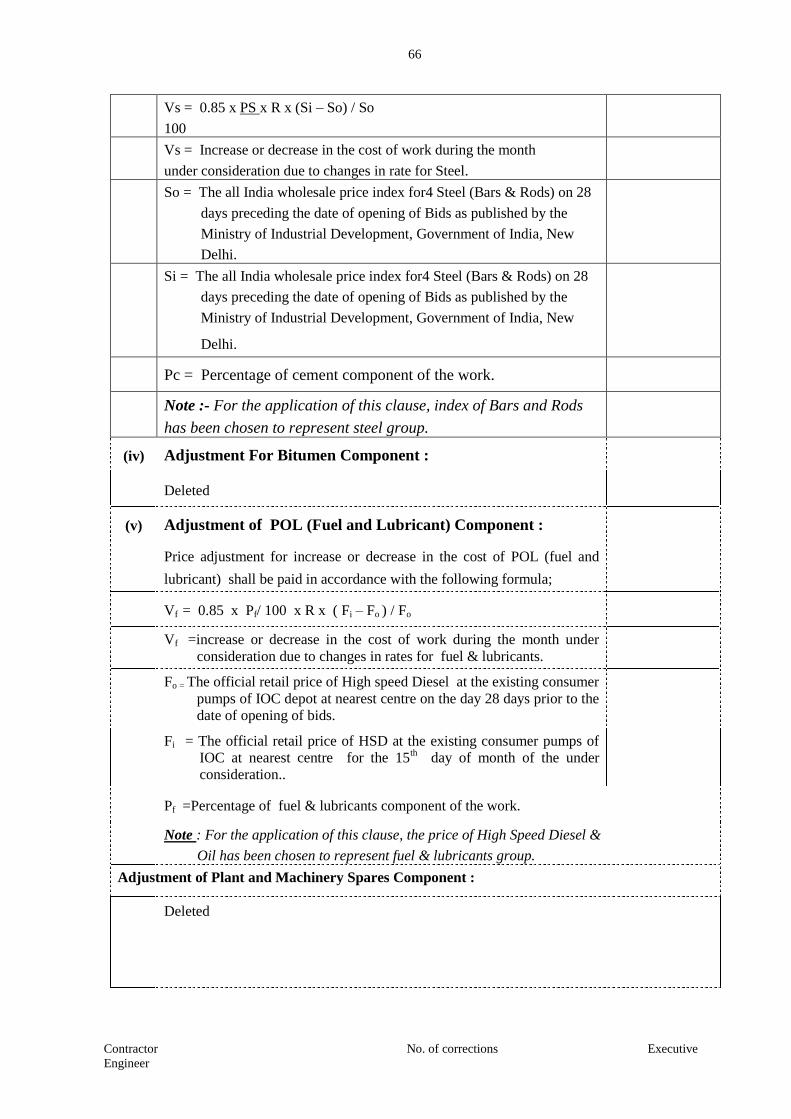
66
Contractor No. of corrections Executive
Engineer
Vs = 0.85 x PS x R x (Si – So) / So
100
Vs = Increase or decrease in the cost of work during the month
under consideration due to changes in rate for Steel.
So = The all India wholesale price index for4 Steel (Bars & Rods) on 28
days preceding the date of opening of Bids as published by the
Ministry of Industrial Development, Government of India, New
Delhi.
Si = The all India wholesale price index for4 Steel (Bars & Rods) on 28
days preceding the date of opening of Bids as published by the
Ministry of Industrial Development, Government of India, New
Delhi.
Pc = Percentage of cement component of the work.
Note :- For the application of this clause, index of Bars and Rods
has been chosen to represent steel group.
(iv) Adjustment For Bitumen Component :
Deleted
(v) Adjustment of POL (Fuel and Lubricant) Component :
Price adjustment for increase or decrease in the cost of POL (fuel and
lubricant) shall be paid in accordance with the following formula;
Vf = 0.85 x Pf/ 100 x R x ( Fi – Fo ) / Fo
Vf =increase or decrease in the cost of work during the month under
consideration due to changes in rates for fuel & lubricants.
Fo = The official retail price of High speed Diesel at the existing consumer
pumps of IOC depot at nearest centre on the day 28 days prior to the
date of opening of bids.
Fi = The official retail price of HSD at the existing consumer pumps of
IOC at nearest centre for the 15th day of month of the under
consideration..
Pf =Percentage of fuel & lubricants component of the work.
Note : For the application of this clause, the price of High Speed Diesel &
Oil has been chosen to represent fuel & lubricants group.
Adjustment of Plant and Machinery Spares Component :
Deleted
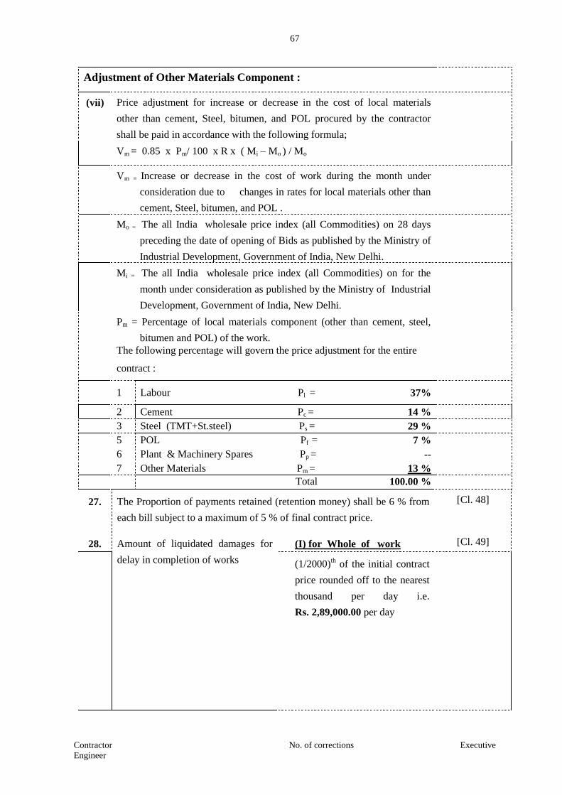
67
Contractor No. of corrections Executive
Engineer
Adjustment of Other Materials Component :
(vii) Price adjustment for increase or decrease in the cost of local materials
other than cement, Steel, bitumen, and POL procured by the contractor
shall be paid in accordance with the following formula;
Vm = 0.85 x Pm/ 100 x R x ( Mi – Mo ) / Mo
Vm = Increase or decrease in the cost of work during the month under
consideration due to changes in rates for local materials other than
cement, Steel, bitumen, and POL .
Mo = The all India wholesale price index (all Commodities) on 28 days
preceding the date of opening of Bids as published by the Ministry of
Industrial Development, Government of India, New Delhi.
Mi = The all India wholesale price index (all Commodities) on for the
month under consideration as published by the Ministry of Industrial
Development, Government of India, New Delhi.
Pm = Percentage of local materials component (other than cement, steel,
bitumen and POL) of the work.
The following percentage will govern the price adjustment for the entire
contract :
1 Labour Pl = 37%
2 Cement Pc = 14 %
3 Steel (TMT+St.steel) Ps = 29 %
5 POL Pf = 7 %
6 Plant & Machinery Spares Pp = --
7 Other Materials Pm = 13 %
Total 100.00 %
27. The Proportion of payments retained (retention money) shall be 6 % from
each bill subject to a maximum of 5 % of final contract price.
[Cl. 48]
28. Amount of liquidated damages for
delay in completion of works
(I) for Whole of work [Cl. 49]
(1/2000)th of the initial contract
price rounded off to the nearest
thousand per day i.e.
Rs. 2,89,000.00 per day

68
Contractor No. of corrections Executive
Engineer
(II) for sectional completion
(Whatever specified in Item 6
of Contract Data) - (1/2000)th of
initial contract price for section
of work under
(i) Milestone I rounded off to
the nearest thousand per day i.e.
Rs. 57,800.00 per day.
(ii) Milestone II rounded off to
the nearest thousand per day i.e.
Rs. 1,01,100.00 per day.
(iii) Milestone III rounded off
to the nearest thousand per day
i.e. Rs. 57,800.00 per day.
(iv) Milestone IV rounded off
to the nearest thousand per day
i.e. Rs. 72,200.00 per day.
29 Maximum limit of liquidated
damages for delay in completion of
work.
10% of the Initial Contract
Price rounded off to the nearest
thousand. i.e.
Rs. 5,77,63,000.00
[Cl. 49]
30. Amount of Bonus for early
completion of whole of the works
DELETED
[Cl. 50]
31. Maximum limit of bonus for early
completion of work
DELETED
[Cl. 50]
32. The amounts of the advance payment
are.
DELETED
[Cl. 51 & 52]
33. The Securities shall be for the following minimum amounts equivalent
as a percentage of the Contract Price:
[Cl. 52]
Performance Security for 2 percent of contract price plus
Rs....................... (to be decided after evaluation of the bid) as additional
security in terms of ITB Clause 29.5

69
Contractor No. of corrections Executive
Engineer
The Standard form of Performance Security acceptable to the Employer
shall be an unconditional Demand Draft (DD) of the type as presented
in Section 8 of the Bidding Documents.
34. The Schedule of Operating and Maintenance Manuals ................N/A [Cl. 58]
70
Contractor No. of corrections Executive
Engineer
SECTION – 5
TECHNICAL SPECIFICATION
71
Contractor No. of corrections Executive
Engineer
TECHNICAL SPECIFICATIONS
1.1 PREAMBLE 1.1 The Technical Specifications contained herein shall be read in conjunction with the other
Bidding Documents as specified in Volume –I, III & IV.
1.2 SITE INFORMATION
1.2.1 The information give hereunder and provided elsewhere in these documents is given in good
faith by the Employer but the Contractor shall satisfy himself regarding all aspects of site
conditions and no claim will be entertained on the plea that the information supplied by the
Employer is erroneous or insufficient.
1.2.2 The area in which the Works are located is plain terrain
1.2.3 General Climatic Conditions
1.2.3.1 The temperature in this region is a under: During summer months, average maximum
temperature is above 40oC.
1.2.3.2 The average annual rainfall in the area is of the order of 500mm
1.2.4 Seismic Zone (Zone III) Exposure condition- Server.
The Works are located in Seismic Zone II as defined in IRC: 6-2000.
2 GENERAL REQUIREMENTS
The Technical Specifications in accordance with which the entire work described hereinafter
shall be constructed and completed by the Contractor shall comprise of the following,
2.1 PART- 1- General Technical Specifications
The General Technical Specifications shall be the “SPECIFICATIONS FOR ROAD AND
BRIDGE WORKS” FIFTH REVISION APRIL 2013, issued by the Ministry of Surface
Transport (Road Wing), Government of India and published by the Indian Roads Congress.
2.2 Maharashtra State Public Works Department Specifications Book.
2.3 PART – II- Supplementary Technical Specifications.
The Supplementary Technical Specifications shall comprise of various Amendments /
Modifications / Additions to the “SPECIFICATION FOR ROAD AND BRIDGE WORKS”
referred to in PART–1 above and Additional Specifications for particular item of Works not
already covered in PART-1.
2.4 A particular clause or a part thereof in “SPECIFICATION FOR ROAD AND BRIDGE
WORKS (FIFTH REVISION, APRIL 2013)’’ referred in PART-I above, where Amended /
Modified / Added upon and incorporated in PART-II, referred to above , such Amended /
Modified / Added upon, and incorporated in PART-II, referred to above, such Amendment /
Modification / Addition supersedes the relevant Clause or part of the Clause.

72
Contractor No. of corrections Executive
Engineer
2.5 The Additional Specifications shall comprises of specifications for particular item of Works not
already covered in PART-I.
2.6 When an Amended / Modified / Added Clause supersedes a Clause or part thereof in the said
Specifications, then any reference to the superseded Clause shall be deemed to refer to the
Amended / Modified /Added Clause or part thereof.
2.7 In so far as Amended / Modified / Added Clause may come in conflict or be inconsistent with
any of the provisions of the said Specifications under reference, the Amended / Modified
/Added Clauses shall always prevail.
2.8 The following Clauses in the “SPECIFICATIONS FOR ROAD AND BRIDGE WORKS
(FIFTH REVISION APRIL 2013)’’ are applicable /Modified for project.
112, 201, 301, 309,401, 404, 408,501, 502, 503,504, 507, 801, 803, 900, 1000, 3000
73
Contractor No. of corrections Executive
Engineer
GENERAL SPECIFICATION FOR WATERPROOFING
(1) The work of waterproofing described in the following items shall be carried out by
the contractor only through a renowned specialist waterproofing agency using
cement waterproofing compounds, as approved in writing by the Engineer-in-
charge.
(2) The Contractor shall give before execution, detailed specifications for each item of
works of waterproofing to be executed according to the specifications of the
specialized agency, he proposes to employ, for approval. The work shall not be
started unless approval in writing is given by the Engineer in charge to the said
specification.
(3) The Contractor shall give a guarantee bond on requisite stamp paper for a minimum
period of 7 years for all the items of waterproofing done. During the guarantee
period the Contractor shall entirely be responsible to rectify any defect at his own
cost to maintain the work in waterproof condition. The waterproofing Contractor
shall also have to make good all the surroundings disturbed by him during the
rectification work at his own cost. The form of written guarantee shall be on a legal
stamped agreement acceptable to the Government. The Guarantee shall be given
within one month from the date of completion of water proofing treatment but any
delay in furnishing the guarantee shall not relieve the contractor from implications
of the clause.
(4) 10% (Ten percent) of the cost of the waterproofing work executed shall be retained
as “Retention Money” for a period of 7 years covering the guarantee, and the same
shall be released only after satisfactory performance of the treatment during
guarantee period of 7 years. This amount may be converted into any approved
interest bearing security (for 7 years after completion of defect liability period), in
the name of Chief Executive Officer, Maharashtra Maritime Board on receipt of
such written request from the contractor.
(5) The waterproofing agency as approved by Engineer-in-charge shall provide and
install at his own cost the following for his own use and remove the same after
completion of the work:

74
Contractor No. of corrections Executive
Engineer
I) Two pumps electrical/ diesel operated for watering and curing of work at any
level in the building. Curing for all items shall be carried out for a minimum period
of 14 days.
II) Temporary Mild Steel Water storage tanks.
III) Temporary galvanized iron pipeings and fittings for water line.
IV) Flexible hose lengths.
V) Cement Godown, site office.
(6) Injections to reinforced cement concrete slab, wherever required, have to be
undertaken by the Contractor free of cost.
(7) Before starting the waterproofing work, the surface receiving the treatment shall be
cleaned properly.
(8) The item of waterproofing as given in the Schedule ‘B’ applies for work in any
position and on any floors and at any heights. The lift of materials shall not form
any criteria for extra payment.
(9) For the reference of contractor, general guideline specifications for waterproofing
are attached herein with the general specification for waterproofing.
General Guidelines for Waterproofing work
For reference of contractor.
(Note : The contractor is required to give detailed specification for each item of waterproofing
work).
1. Roof, Slab and terrace:
Providing. average 112 mm thick cement based Indian waterproofing treatment with
Brick Bat Coba beading by keeping the treatment minimum 75 mm thick at the rain water
pipe point and keeping the gradient not flatter than 1 in 100.
a) Cleaning the surface to the requirements.
b) Giving a coat of wash mixed with cement.
75
Contractor No. of corrections Executive
Engineer
c) Providing 12mm thick cement mortar bed, with admixture of waterproofing compound to
form a bed for brickbats. Special care shall be taken at the junction of parapet and terrace
slab to ensure gaps, if any, are properly sealed.
d) Placing brickbats of varying size (average 80 mm thick) to proper slope and grouting
their joints with chemical process in cement mortar with 2% of waterproofing
compound.
e) Providing all around the terrace large waterproof wattas (rounding’s) up to a height of
30 cm in PCC or as directed above the finished level of waterproof treatment.
f) Finishing: Finishing the top surface with average 20 mm thick layers of cement mortar
1:3 added with jute fibre at one kilogram per bag, including finishing the surface smooth
with cement slurry mixed with approved waterproofing compound, marking finished
surface with false squares of 300mmx300 mm.
g) Curing: Curing shall be done for 14 days. Curing of top surface shall be done by
making base ( wattas ) with lean cement mortar to keep water standing on the surface.
h) Carrying out the test: The test shall be carried out by pounding method. Payment for
the item shall be released only after results of pond test are satisfactory.
2. Toilets:
a) Cleaning the surface to the department’s requirements.
b) Giving a coat of wash mixed with cement.
c) Providing average 15 cm thick waterproofing treatment to the bottom of toilet floors.
d) Providing 20 mm to 25 mm thick cement mortar waterproof treatment to the walls of
toilets up to the height of 0.30 metre above the finished floor level.
e) Providing waterproof wattas all around the toilets.
f) Grouting the mouths of inlets and outlets
g) Filling sunk portion with brickbats including waterproof mortar and the top surface
left rough to form a key fortiles.
3. Overhead tanks :
Work under some items in Schedule 'B' of the tender pertains to constructionoverhead
water tank. After completion of the work, water tank as a whole shall be tested for water
tightness and leakages if any shall be rectified forthwith 'without any extra cost to the
department.
76
Contractor No. of corrections Executive
Engineer
GUARANTEE BOND FOR WATERPROOFING WORK
(On stamp paper worth Rupees 100/-)
Name of work :
Name of Agency :
Agreement No. :
The contractor hereby declares that the water proofing work carried out under this
contract shall be of the best quality and workmanship and shall strictly in accordance
with the specifications and particulars contained/mentioned in the clause hereof and the
contractor hereby guarantee that the said work should continue to conform to the
description and quality aforesaid for a period of Ten years from the date of handing over
the said work to the Department and notwithstanding the fact that the Department may
have inspected and or approved the said work. If during the aforesaid period of Ten
years, the said work be discovered not to conform to the description and quality aforesaid
for a period of Ten years from the date of handling over the said work to the
Department and notwithstanding the fact that Department may have inspected and or
approved the said work. If during the aforesaid period of Ten years, the said work be
discovered not to conform to the description and quality aforesaid or have deteriorated
(and the decision of the Engineer in charge in that behalf will be final and conclusive)
the department will be entitled to reject the said work or such portion thereof as may be
discovered not to conform to the said description and quality. On such rejection, the
work will be at the contractor’s risk and all the provisions herein contained relating to
rejection of work etc. shall apply. The contractor shall, if so called upon, have to make
good the work etc. or such portion thereof, as is rejected by the Engineer in charge,
otherwise the contractor shall pay to the Department, such damages, as may arise by the
reason of the breach of the condition herein contained. Nothing herein contained shall
prejudice any other right of the Department in that behalf under this contract or
otherwise.
Date :
Place : Contractor

77
Contractor No. of corrections Executive
Engineer
hÉÉÇSÉÒ +É´ÉEò +ÉÊhÉ JÉ{É ªÉÉÆSÉÉ Ê½þ¶Éä¤É nùÉJÉÊ´ÉhÉÉ®úÒ
xÉÉånù´É½þÒ Gò¨ÉÉÆEò 1
EòɨÉÉSÉä xÉÉÆ´É :- -----------------------------------------------------------------------------
¨ÉÉMÉÒ±É ºÉ{iÉɽþÉ{ÉɺÉÖxÉ EòɨÉÉSªÉÉ Ê`öEòÉhÉÒ +ºÉ±Éä±ÉÒ Ê¶É±±ÉEò
+É´ÉEò +ÉÊhÉ JÉ{É ªÉÉÆSÉÉ Ê½þ¶Éä¤É
ÊnùxÉÉÆEò MÉÉb÷Ò Gò¨ÉÉÆEò ʨɳýɱÉ䱪ÉÉ {ÉÉäiªÉÉÆSÉÒ
ºÉÆJªÉÉ
´ÉÉ{É®ú±É䱪ÉÉ {ÉÉäiªÉÉÆSÉÒ
ºÉÆJªÉÉ
Ênù´ÉºÉÉSªÉÉ +JÉä®úÒºÉ
EòɨÉÉSªÉÉ Ê`öEòÉhÉÒ
®úÉʽþ±Éä±ÉÒ {ÉÉäiÉÒ
BEÚòhÉ
EÆòjÉÉ]õnùÉ®úÉSÉÒ ºÉ½þÒ +ʦɪÉÆiªÉÉSÉÒ ºÉ½þÒ
xÉÉånù´É½þÒ Gò¨ÉÉÆEò 2
ÊxÉ®úÊxÉ®úɳýªÉÉ ¤ÉɤÉÓ´É®ú +É`ö´Éb÷ªÉÉƨÉvªÉä ={ɪÉÉäMÉÉiÉ +ÉhɱÉä +ɴɶªÉEò +ºÉ±Éä±Éä ʺɨÉå]õ {ÉÊ®ú¨ÉÉhÉ ´É |ÉiªÉIÉÉiÉ ={ɪÉÉäMÉÉiÉ
+ÉhɱÉä±Éä {ÉÊ®ú¨ÉÉhÉ ªÉÉÆSÉÒ iÉÖ±ÉxÉÉ nùÉJÉÊ´ÉhÉÉ®äú EòÉä¹]õEò
+É`ö´Éb÷ªÉɨÉvªÉä Eäò±É䱪ÉÉ EòɨÉÉSÉä BEÚòhÉ +ÆnùÉVÉ {ÉÊ®ú¨ÉÉhÉ
+.Gò ¤ÉÉ¤É BEÚòhÉ +ÆnùÉVÉ {ÉÊ®ú¨ÉÉhÉ
1

78
Contractor No. of corrections Executive
Engineer
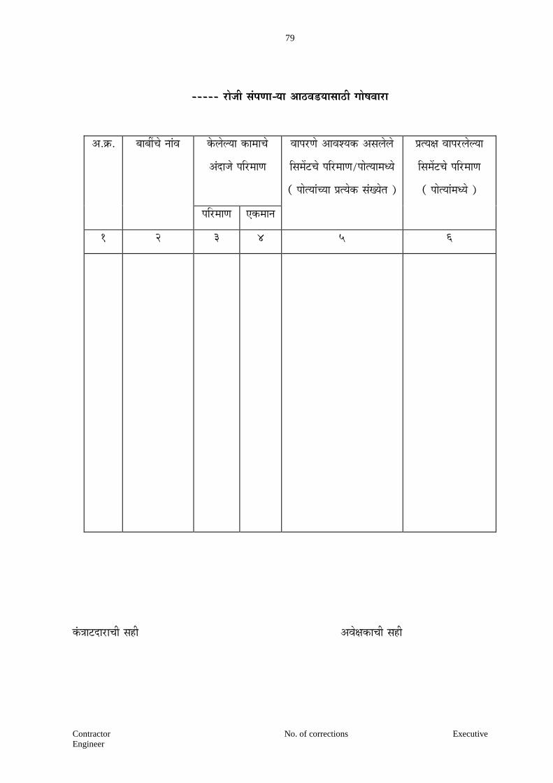
79
Contractor No. of corrections Executive
Engineer
----- ®úÉäVÉÒ ºÉÆ{ÉhÉɪÉÉ +É`ö´Éb÷ªÉɺÉÉ`öÒ MÉÉä¹É´ÉÉ®úÉ
+.Gò. ¤ÉɤÉÓSÉä xÉÉÆ´É Eäò±É䱪ÉÉ EòɨÉÉSÉä
+ÆnùÉVÉä {ÉÊ®ú¨ÉÉhÉ
´ÉÉ{É®úhÉä +ɴɶªÉEò +ºÉ±Éä±Éä
ʺɨÉå]õSÉä {ÉÊ®ú¨ÉÉhÉ/{ÉÉäiªÉɨÉvªÉä
( {ÉÉäiªÉÉÆSªÉÉ |ÉiªÉäEò ºÉÆJªÉäiÉ )
|ÉiªÉIÉ ´ÉÉ{É®ú±É䱪ÉÉ
ʺɨÉå]õSÉä {ÉÊ®ú¨ÉÉhÉ
( {ÉÉäiªÉÉƨÉvªÉä )
{ÉÊ®ú¨ÉÉhÉ BEò¨ÉÉxÉ
1 2 3 4 5 6
EÆòjÉÉ]õnùÉ®úÉSÉÒ ºÉ½þÒ +´ÉäIÉEòÉSÉÒ ºÉ½þÒ

80
Contractor No. of corrections Executive
Engineer
{ÉÉä±ÉÉnùÉSÉÒ +É´ÉEò +ÉÊhÉ JÉ{É ªÉÉÆSÉÉ Ê½þ¶Éä¤É nùÉJÉÊ´ÉhÉÉ®úÒ
xÉÉånù´É½þÒ Gò¨ÉÉÆEò 1
EòɨÉÉSÉä xÉÉÆ´É :- -----------------------------------------------------------------------------
¨ÉÉMÉÒ±É ºÉ{iÉɽþÉ{ÉɺÉÖxÉ EòɨÉÉSªÉÉ Ê`öEòÉhÉÒ +ºÉ±Éä±ÉÒ Ê¶É±±ÉEò
+É´ÉEò +ÉÊhÉ JÉ{É ªÉÉÆSÉÉ Ê½þ¶Éä¤É
ÊnùxÉÉÆEò MÉÉb÷Ò Gò. ʨɳýɱÉ䱪ÉÉ
{ÉÉä±ÉÉnùÉSÉä ´ÉVÉxÉ
´ÉÉ{É®ú±É䱪ÉÉ {ÉÉä±ÉÉnùÉSÉä
´ÉVÉxÉ
Ênù´ÉºÉÉSªÉÉ +JÉä®úÒºÉ
ʶɱ±ÉEò {ÉÉä±ÉÉnùÉSÉä ´ÉVÉxÉ
BEÚòhÉ
EÆòjÉÉ]õnùÉ®úÉSÉÒ ºÉ½þÒ +ʦɪÉÆiªÉÉSÉÒ ºÉ½þÒ
xÉÉånù´É½þÒ Gò¨ÉÉÆEò 2
ÊxÉ®úÊxÉ®úɳýªÉÉ ¤ÉɤÉÓ´É®ú +É`ö´Éb÷ªÉÉƨÉvªÉä ={ɪÉÉäMÉÉiÉ +ÉhɱÉä +ɴɶªÉEò +ºÉ±Éä±Éä {ÉÊ®ú¨ÉÉhÉ ´É |ÉiªÉIÉÉiÉ ={ɪÉÉäMÉÉiÉ
+ÉhɱÉä±Éä {ÉÊ®ú¨ÉÉhÉ ªÉÉÆSÉÒ iÉÖ±ÉxÉÉ nùÉJÉÊ´ÉhÉÉ®äú EòÉä¹]õEò
+É`ö´Éb÷ªÉɨÉvªÉä Eäò±É䱪ÉÉ EòɨÉÉSÉä BEÚòhÉ +ÆnùÉVÉ {ÉÊ®ú¨ÉÉhÉ
+.Gò ¤ÉÉ¤É BEÚòhÉ +ÆnùÉVÉ {ÉÊ®ú¨ÉÉhÉ
1
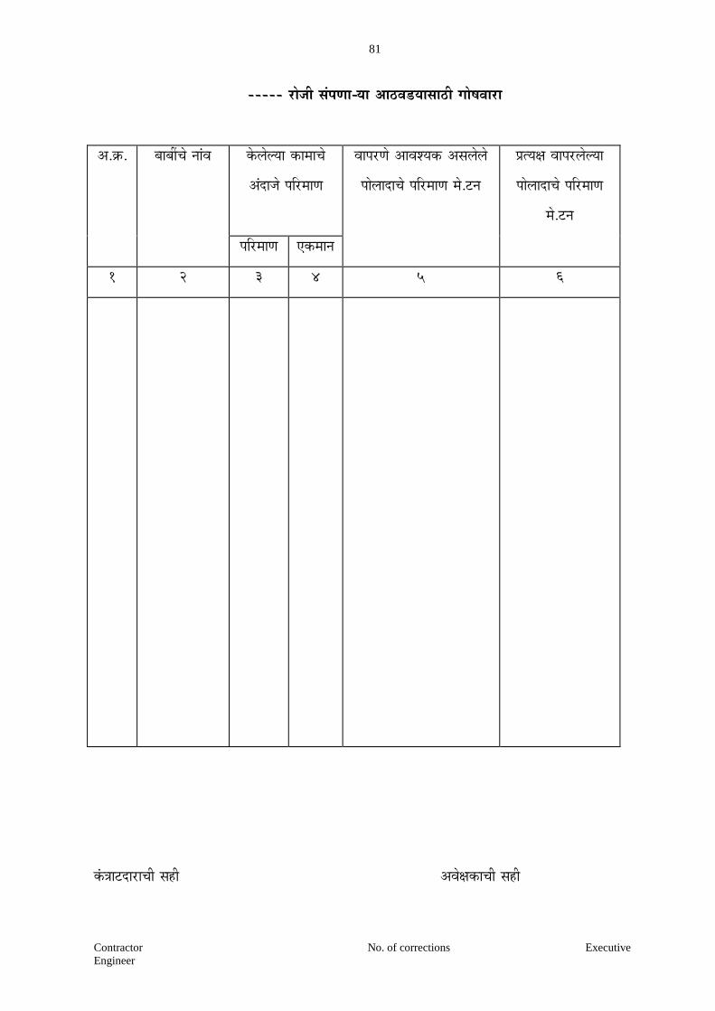
81
Contractor No. of corrections Executive
Engineer
----- ®úÉäVÉÒ ºÉÆ{ÉhÉɪÉÉ +É`ö´Éb÷ªÉɺÉÉ`öÒ MÉÉä¹É´ÉÉ®úÉ
+.Gò. ¤ÉɤÉÓSÉä xÉÉÆ´É Eäò±É䱪ÉÉ EòɨÉÉSÉä
+ÆnùÉVÉä {ÉÊ®ú¨ÉÉhÉ
´ÉÉ{É®úhÉä +ɴɶªÉEò +ºÉ±Éä±Éä
{ÉÉä±ÉÉnùÉSÉä {ÉÊ®ú¨ÉÉhÉ ¨Éä.]õxÉ
|ÉiªÉIÉ ´ÉÉ{É®ú±É䱪ÉÉ
{ÉÉä±ÉÉnùÉSÉä {ÉÊ®ú¨ÉÉhÉ
¨Éä.]õxÉ
{ÉÊ®ú¨ÉÉhÉ BEò¨ÉÉxÉ
1 2 3 4 5 6
EÆòjÉÉ]õnùÉ®úÉSÉÒ ºÉ½þÒ +´ÉäIÉEòÉSÉÒ ºÉ½þÒ
82
Contractor No. of corrections Executive
Engineer
DECLARATION OF THE CONTRACTOR
I/We hereby declare that I/we have made me / us thoroughly conversant with the local
conditions regarding all materials and labour on which I/we have based my/our rates for this
tender. The specifications and lead of materials on this work have been carefully studied and
understood by me/us before submitting this tender. I/we undertake to use only the best materials
approved by the Chief Executive Officer, Maharashtra Maritime Board, Indian Mercantile
Chamber, 3rd
floor, Ramjibhai Kamani Marg, Ballard Estate, Mumbai-400 001 or his duly
authorised representative before starting the work and to abide by his decision.
I/We hereby undertake to pay the labourers engaged on the work as per minimum wages
Act 1948 applicable to the Zone concerned.
Signature of Contractor

83
Contractor No. of corrections Executive Engineer
33. ADDITIONAL TECHNICAL CONDITIONS
33.1 The work shall be carried out in the best workmanship like manner and in strict accordance
with P.W.D. hand book Volume I & II 1960. Edition supplemented by specification attached
and as per Standard Specifications Book of Government of Maharashtra of 1979 and as per
specific order of the Executive Engineer or his representative from time to time.
33.2 The orders issued by the Government in P.W. Department and the Superintending Engineer,
from time to time regarding construction procedure shall be binding on the contractor in
addition to the specification contained in P.W.D. hand book Volume I & II and book of
standard specification of P.W. Department and the specifications enumerated above.
33.3 The contractor shall submit day to day account of the materials issued to him and its use and
also monthly progress and programme of work.
33.4a) The concrete mix design shall be got approved from Engineer in charge and the mix
design shall give preliminary strength of 1.33 times working strength.
b) The maximum size of aggregate permissible would be as per A-7 page-8 of Standard
Specifications Book 1979 Edition.
33.5 The items provided with watering for curing include continuous watering operations
throughout the day including lunch hours and also during holidays. For this purpose
contractor shall have to construct tank of. 5000 liters capacity near each building and provide
necessary Booster Pumps etc. to ensure adequate curing and wetting. Hold fasts coming in
contact with R.C.C. columns shall be of sizes 30 cm x 4 cm to be fitted with two rows, nails
fixed properly in concrete.
33.6 For all sand covering items, use of washed mixer sand (with sand washing machine) is
obligatory. No separate claim in this regard will be entertained.
33.7 Material testing requirement frequency and type of testing is enclosed separately. Material to
be used shall be tested accordingly and cost shall be borne by contractor.
33.8 For R.C.C. centering plywood and M.S. sheet of approved quality shall be used and
adjustable props and fasteners shall be used.
33.9 The execution of any work from external side of the building 'H' frame steel scaffolding shall
be used. No separate payment for claims in this regard shall be entertained.
33.10 The scaffolding shall not be supported on existing external walls of the building by making
holes in it and also the scaffolds shall not rest on any part of the building.
33.11 Quality Assurance Manual: Contractor shall prepare the quality assurance manual booklet in
consultation with the Executive Engineer. Quality assurance manual shall be comprehensive
document covering every aspect of the work. Superintending Engineer shall approve this
document. The quality manual document shall be used only after approval from

84
Contractor No. of corrections Executive Engineer
Superintending Engineer. Provision of the quality manual is binding on the contractor.
Quality manual shall be treated as a legal document as per with this contract document. It
shall be used till the work is completed in full respect.
34. SPECIAL CONDITIONS FOR QUALITY CONTROL TESTS AND FREQUENCY
34.1 Overall quality of the work depends on the quality of ingredient material being used in the work and
exercising adequate control over it. It is therefore prime responsibility of the Contractor to get the
ingredient material and product tested strictly as per the frequencies stipulated in the Annexure.
34.2 The Quality Control test shall be carried out at various stages of work wise selection of material to be
procured for work, acceptance of procured material before its use on the work, in view of its strength,
durability, serviceability etc. and as directed by Engineer-in-charge for any other reason of public
interest.
34.3 The entire charges towards testing such as sampling, carrying samples to Lab testing of samples etc.
will have to be borne by the Contractors.
34.4 The right of acceptance/rejection of material/work done specified above is reserved by Engineer-in-
charge in view of non confirmation to frequency of testing.
34.5 In case of failure to observe the frequency of testing by the contractor the Engineer-in-charge will be
at liberty to recover testing charges fixed by the dep’t. At penal rate. The penal rate will be two times
the prevailing testing charges.
34.6 SAMPLES AND TESTING MATERIALS
(A) All material to be used on civil construction work shall be got approved in advance from the
Engineer-in charge and for furniture work wood, plywood, laminates, veneer etc. from Architect
and Engineer in charge and shall pass the lest and / or analysis required by him which will be :
(i) As specified in the specification for the items concerned and / or
(ii) ISI Specifications (whichever and wherever applicable) or
(iii) Such recognised specifications acceptable to Engineer-in-charge as equivalent there to or in
absence or such authorised specification.
(iv) Such requirement test and / or. analysis as may be specified by the Engineer -in-charge in
order of precedence given above.
(B) The contractor shall at his risk and cost make all arrangements and / or shall provide for all
such facilities as the Engineer-in-charge may require for collecting, preparing required
number of samples for tests or for analysis at such time and to such place or places as may be
directed by the Engineer and bear all charges and cost of testing. Such. samples shall also be
deposited with the Engineer-in-charge.
(C) The contractor shall if and when required, submit at his cost the samples of materials to be
tested or analysed and if, so directed shall not make use of or incorporate in the work any
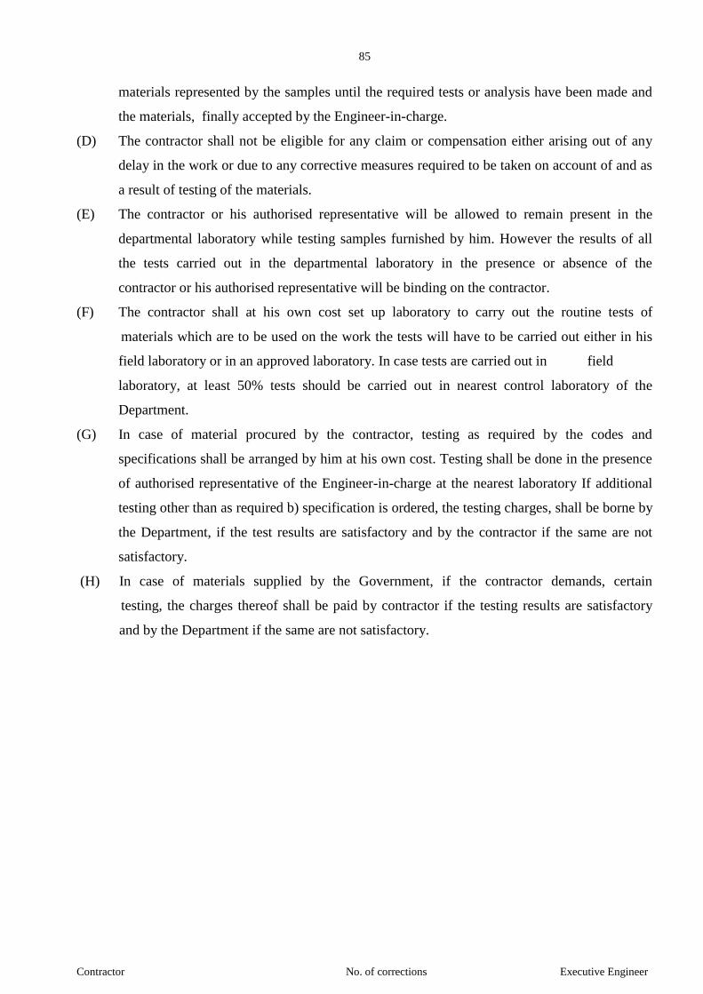
85
Contractor No. of corrections Executive Engineer
materials represented by the samples until the required tests or analysis have been made and
the materials, finally accepted by the Engineer-in-charge.
(D) The contractor shall not be eligible for any claim or compensation either arising out of any
delay in the work or due to any corrective measures required to be taken on account of and as
a result of testing of the materials.
(E) The contractor or his authorised representative will be allowed to remain present in the
departmental laboratory while testing samples furnished by him. However the results of all
the tests carried out in the departmental laboratory in the presence or absence of the
contractor or his authorised representative will be binding on the contractor.
(F) The contractor shall at his own cost set up laboratory to carry out the routine tests of
materials which are to be used on the work the tests will have to be carried out either in his
field laboratory or in an approved laboratory. In case tests are carried out in field
laboratory, at least 50% tests should be carried out in nearest control laboratory of the
Department.
(G) In case of material procured by the contractor, testing as required by the codes and
specifications shall be arranged by him at his own cost. Testing shall be done in the presence
of authorised representative of the Engineer-in-charge at the nearest laboratory If additional
testing other than as required b) specification is ordered, the testing charges, shall be borne by
the Department, if the test results are satisfactory and by the contractor if the same are not
satisfactory.
(H) In case of materials supplied by the Government, if the contractor demands, certain
testing, the charges thereof shall be paid by contractor if the testing results are satisfactory
and by the Department if the same are not satisfactory.
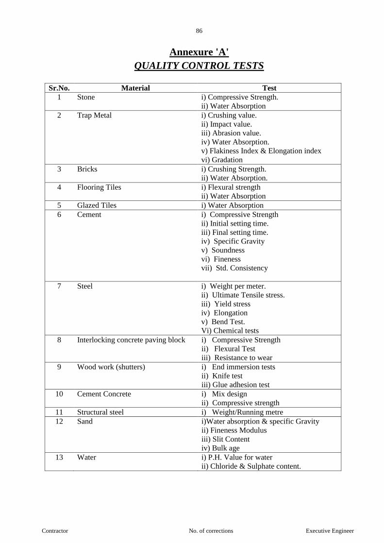
86
Contractor No. of corrections Executive Engineer
Annexure 'A'
QUALITY CONTROL TESTS
Sr.No. Material Test
1 Stone i) Compressive Strength.
ii) Water Absorption
2 Trap Metal i) Crushing value.
ii) Impact value.
iii) Abrasion value.
iv) Water Absorption.
v) Flakiness Index & Elongation index
vi) Gradation
3 Bricks i) Crushing Strength.
ii) Water Absorption.
4 Flooring Tiles i) Flexural strength
ii) Water Absorption
5 Glazed Tiles i) Water Absorption
6 Cement i) Compressive Strength
ii) Initial setting time.
iii) Final setting time.
iv) Specific Gravity
v) Soundness
vi) Fineness
vii) Std. Consistency
7 Steel i) Weight per meter.
ii) Ultimate Tensile stress.
iii) Yield stress
iv) Elongation
v) Bend Test.
Vi) Chemical tests
8 Interlocking concrete paving block i) Compressive Strength
ii) Flexural Test
iii) Resistance to wear
9 Wood work (shutters) i) End immersion tests
ii) Knife test
iii) Glue adhesion test
10 Cement Concrete i) Mix design
ii) Compressive strength
11 Structural steel i) Weight/Running metre
12 Sand i)Water absorption & specific Gravity
ii) Fineness Modulus
iii) Slit Content
iv) Bulk age
13 Water i) P.H. Value for water
ii) Chloride & Sulphate content.
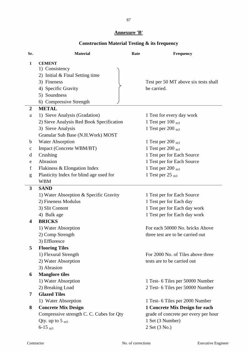
87
Contractor No. of corrections Executive Engineer
Annexure 'B'
Construction Material Testing & its frequency
Sr. Material Rate Frequency
1 CEMENT
1) Consistency
2) Initial & Final Setting time
3) Fineness
4) Specific Gravity
5) Soundness
6) Compressive Strength
Test per 50 MT above six tests shall
be carried.
2 METAL
a 1) Sieve Analysis (Gradation) 1 Test for every day work
2) Sieve Analysis Red Book Specification 1 Test per 100 m3
3) Sieve Analysis
Granular Sub Base (N.H.Work) MOST
1 Test per 200 m3
b Water Absorption 1 Test per 200 m3
c Impact (Concrete WBM/BT) 1 Test per 200 m3
d Crushing 1 Test per for Each Source
e Abrasion 1 Test per for Each Source
f Flakiness & Elongation Index 1 Test per 200 m3
g Plasticity Index for blind age used for
WBM
1 Test per 25 m3
3 SAND
1) Water Absorption & Specific Gravity 1 Test per for Each Source
2) Fineness Modulus 1 Test per for Each day
3) Slit Content 1 Test per for Each day work
4) Bulk age 1 Test per for Each day work
4 BRICKS
1) Water Absorption
2) Comp Strength
3) Effloresce
For each 50000 No. bricks Above
three test are to be carried out
5 Flooring Tiles
1) Flexural Strength
2) Water Absorption
3) Abrasion
For 2000 No. of Tiles above three
tests are to be carried out
6 Manglore tiles
1) Water Absorption
2) Breaking Load
1 Test- 6 Tiles per 50000 Number
2 Test- 6 Tiles per 50000 Number
7 Glazed Tiles
1) Water Absorption 1 Test- 6 Tiles per 2000 Number
8 Concrete Mix Design 1 Concrete Mix Design for each
Compressive strength C. C. Cubes for Qty grade of concrete per every per hour
Qty. up to 5 m3 1 Set (3 Number)
6-15 m3 2 Set (3 No.)

88
Contractor No. of corrections Executive Engineer
16-30 m3 3 Set (3 No.)
31-50 m3 4 Set (3 No.)
Quantity above 51 m3 4+1 additional set per 50 m3
9 MURUM/ SOIL for earth work
1) Optimum Dry Density 2 Test per 3000 m3
2) C.B.R. 1 Test per 3000 m3
3) Liquid & Plastic Limit/Plasticity Index 1 Test per 3000 m3
4) Filed Density 100% P.D. 1 Test per 3000 m3
5) Filed Moisture Content 1 Test per 3000 m3
10 WOOD
1) Moisture Content 1 test per Source
2) Density 1 test per Source
11 WATER
1) P.H. Value for Water and Sand 1 test per Source
2) Chloride & Sulphate content 2 test per Source
12 Steel
1) Wt per meter
2) Ultimate Tensile Stress
3) Yield stress
4) Elongation
One test for every 5.0 MT or part
thereof for each diameter
89
Contractor No. of corrections Executive Engineer
ADDITONAL SPECIFICATIONS
The contractor shall achieve that following requirements in respect of quantity of work and
his contract rate shall provided for the same.
1.1 ADMIXTURES:-
Whenever necessary the admixture should be used to achieved the required workability. The
type of admixture should be got approved from Engineer-in-charge. The rate is inclusive of all
admixtures etc. if found necessary.
1.2 CEMENT CONCRETE IN CONCRETE:
For this purpose the conditions mentioned in additional specifications on Page 115 to
121shall be applicable.
1.3 WATER / CEMENT RATIO:
For high quality concrete of low permeability, the water/cement ratio shall not be more than
0.45 and preferably 0.40 or less subject to the attainment of adequate workability.
1.4 CURING FOR CONCRETE:
Special attention shall be paid to curing of concrete in order to ensure maximum durability
and no minimize cracking. Concrete shall be cured with fresh water whenever it is possible to
ensure that the concrete surface can be kept wet despite wind, etc. care shall be taken on avoid
rapid lowering of concrete temperatures caused by applying cold water to hot concrete surface
(thermal shock) Sea water shall not be used for curing reinforced concrete or prestressed
concrete. Where there is doubt about the ability to keep concrete surface permanently wet for the
whole of the curing period heavy duty membranes curing compound shall be used.
1.5 CONCRETE COVER TO REINFORCEMENT:
(i) The cover concrete must be of the same quality, impermeability and strength as the
rest of the concrete. Special mix design should be carried out for the concrete to be
used for making concrete cover blocks.
(ii) The concrete cover must develop sufficient alkalinity, and protect the steel. The
alkalinity developed shall not be less than 0.04 N and shall not more than 0.08 N.
(iii) The cover must be uniform throughout and it's thickness shall be exclusive of plaster
or other decorative finishes.
(iv) The concrete cover shall be as per the relevant clause of IS codes. In the case of poles
the cover thickness shall be separately decided by the Engineer in charge.
(v)
1.6 DETAILING OF MISCELLANEOUS ITEM :
Binding Wires : All ends of binding wires shall be carefully turned inwards so that they do
not project out of concrete and start rusting action. Plastic coated galvanised wires shall be used.
Wherever possible polythene binding string and polythene bar grips shall be used, after making

90
Contractor No. of corrections Executive Engineer
sure that these do not result in loss of bond or chemical reaction with concrete. The use is subject
to approval of Engineer-in-charge.
1.7 BAR SPACING : As per relevant I.S. codes and as detailed design drawing or as directed by
Engineer-in-charge.
1.8 HOLLOWS IN CONCRETE: After concreting is complete the concrete surface particularly
where there is congestion of reinforcement, shall be tested by light hammering or if possible by
Schmitz hammer. Any portion showing signs of hollowness should be grouted immediately.
SPECIFICATION FOR FORMWORK AND STEEL, CENTERING :-
I) FORMWORK:-
1.1 Formwork: - Formwork shall include all temporary forms of moulds required for forming the
concrete which is cast-in-situ, together with all temporary construction required for their support.
Unless otherwise stated all formwork shall conform to I.S. Specification.
1.2 Design of Formwork: - Formwork including complete false work shall be designed by the
contractor in accordance with I.S.: 2750 (1964), 4041 (1987) and all other relevant I.S. codes
without any extra cost to the Government and these shall be got approved from Engineer
before any formwork is taken up.
1.3 The contractor shall entirely be responsible for the adequacy and safety for false work not-
withstanding any approval or review by the Engineer of his drawing and design. Proprietary
system of formwork if used a detailed information shall be furnished to the Engineer for
approval.
2. QUALITY OF SHUTTERING: The shuttering shall have smooth and even surface and its
joints shall not permit leakage of cement slurry.
2.1 Ply-board shuttering materials to be used shall be steel shuttering/marine plywood well
seasoned free from projecting nails, splits or other defects that may mark on the surface of
concrete. It shall not be so dry as to absorb water from concrete, or so green or wet as to
shrink after erection. Mild steel plates or plywood shall be used for slab and beam bottoms.
2.2 The timber shall be accurately spawned planed on the sides and the surface coming in contact
with concrete.
2.3 So far as practicable, clamps shall be used to hold the forms together. Where use of nails is
unavoidable minimum number of nails shall be used and these shall be left projecting so that
they can be easily with drawn. Use of double headed nails shall be preferred.
3. TOLERANCE:-
3.1 The formwork shall be made so as to produce finished concrete true to shape, lines, levels
plumb and dimensions as shown on the drawings, subject to the following tolerance unless
otherwise specified in these documents or drawings or as directed by the Engineer :
a) Section dimension = 5 mm
91
Contractor No. of corrections Executive Engineer
b) Plumb = 1 in 1000 of height
c) Levels = 3 mm before any deflection takes place.
3.2 Tolerance given above are specified for local aberrations in the finished concrete surface and
should not be taken as tolerance for the entire structure taken as a whole or for the setting and
alignment of formwork which should be as accurate as possible to the entire satisfaction of
the Engineer, Errors if noticed in any lift/ tilt of the structure after stripping of forms, shall be
corrected in the subsequent work to bring back the surface of the structure to its true
alignment.
4. SPECIAL PROVISION: - Whenever the concreting of thinner members in required to be
carried out within shutters of considerable depth, temporary openings in the side of the
shutters shall, if so directed by the Engineer be provided to facilitate the poring and
consolidation of the concrete. Small temporary openings shall be provided as necessary at the
bottom of shutters of walls and deep beams to permit the expulsion of rubbish etc.
5. REMOVAL OF FORMWORK: - The formwork shall be so removed that it shall not cause
damage to concrete. Centring shall be gradually and uniformly lowered in such a manner as
to avoid any shock or vibrations. Supports shall be removed in such a manner as to permit the
concrete to take stresses due to its own weight uniformly and gradually.
The whole of the formwork removal should be planned and definite scheme of operation shall
be worked out. Under no circumstances forms be struck until the concrete reaches a strength
of at least twice the stress to which the concrete may be subjected at the time of striking but
not before the period as mentioned in IS:456-2000 where ordinary Portland cement is used.
II) STEEL CENTERING:-
1. Work include :- Erecting steel centering with contractor's material comprising of standard
steel adjustable props and standard steel trusses / joists / spans, centering place for bottom of
slab and steel plates for bottom of beams etc. of adequate strength properly balanced for
obtaining adequate rigidity to with stand all loads coming on it including permanent and
temporary fixtures and fastenings etc. complete for R.C.C. member like beams slabs and
canopy including its removal after the specified period, stacking making good the damaged
parts / its replacement before its next use with all leads and lift (all centering material shall be
contractor.)
2. For R.C.C. works formwork shall be of marine plywood of adequate thickness and grade
only. The centering and supporting arrangement such as standard steel trusses/ joists/ spans
standards adjustable/ fixed props. H type frames etc. shall be designed by the Contractor and
approved from the Engineer before commencement of its erection. The Contractor with the
prior approval of the Engineer shall use standard steel centering arrangement which may be
manufactured by the reputed firm.

92
Contractor No. of corrections Executive Engineer
3. The supporting arrangement designed by the contractor shall conform to the relevant I.S.
code and Standard practice adopted in this type of work. The centering arrangement shall be
adequately braced and properly secured by using appropriate type of fastenings and fixtures
to ensure stability and rigidity of the centering to withstand all loads coming on it. The entire
responsibility for design, erection, maintenance and safety etc. will exclusively rest with the
contractor. The Engineer reserves right to call detailed design calculations of the entire
centering or part thereof to verify its stability and also reserve tight to reject entire centering
arrangement or part thereof and any material used for the centering in the event of which the
contractor shall have to arrange for its replacement at his own cost.
SPECIFICATIONS FOR CONCRETE WORKS:-
1 DESIGN OF CEMENT CONCRETE MIXES:
a) All the cement concrete of grade M-15 and higher strength shall be done with proper mix
design as per IS: 10262 - 1982 and shall confirm to the durability and other requirements of
IS 456 2000. The mix design shall be got approved from the Executive Engineer from time to
time whenever there is change in the source and type of cement and aggregates and change in
the gradation of aggregates.
b) The design of concrete mixes for various concrete items in the work shall be obtained by the
contractor at his cost from and approved laboratory. The contractor shall submit in advance
details of such design to the Engineer-in-charge for his prior approval.
c) For concrete of Grade M-25/ M-30/M-35.
Preliminary mix design must be carried out from an approved laboratory, for subsequent
changes field mix design shall be acceptable. However in case the Executive Engineer has
got difficulty in acceptance of the field mix design, laboratory mix design shall be got done
by the contractor from approved laboratory at his own cost. Cement, find aggregate and
coarse aggregate must be used by weight only according to the requirement of the approved
mix design.
d) The concrete mix design shall give target strength of 1.33 times the working strength.
e) The minimum size of aggregate permissible shall be as per Para A-7 of Page - 8 f of standard
specification book of 1979 Edition Vol. 1.
f) The provision of the specification No. B-7 at page - 38 to 40 of Vol. 1 1979 Edition of
standard specification book for controlled concrete shall be applicable for all the structural
concrete items. The maximum water cement ratio shall be 0.45. The mix design shall be done
accordingly.
g) All the expenses of preliminary mix design, subsequent field/ laboratory mix design, work
tests, shall be borne by the contractor.

93
Contractor No. of corrections Executive Engineer
2. FROMWORK FOR CONCRETE WORK: - The forms of concrete shall be of the
materials as directly by the Executive Engineer-in-charge and shall preferably be of steel or
plywood, Forms shall be of the required shape, profile and lines. Suitable devices shall be
used to hold corners, adjacent ends, edges of panel or other forms together in accurate
alignment. The forms and joints shall tight enough. Forms used for circular curved or
structures of unusual shape, petal dome etc. shall be of such a character that will result in
smooth concrete surface and exact shape. They shall be prepared such that they will not warp
or distort during erection or while placing concrete. Their design and layout shall be got
approved form the Executive Engineer-in-charge in advance.
3. ERECTION AND REMOVAL OF FORM WORK: - The centering and strutting shall be
of steel or plywood board exclusively for concreting. The design and drawing should be got
approved in advance from the Department. For minor members the Engineer-in-charge may,
at his discretion, permit use of wooden shuttering. The centering and shuttering shall be close
and tight to prevent leakage of cement slurry. The centering shall have the necessary props,
bracing and edges sufficiently strong and stable which shall not yield or displace while or
after lying of concrete. They shall be made in such way that they can be slackened and
removed gradually and slowly without distributing the concrete. Centering and shuttering
shall not be removed before the design strength is achieved.
4. MIXTURE OF CONCRETE: - Design mix concrete as well as nominal mix concrete shall
be mixed by following the provision in Standard specification at B. 6.4 unless otherwise
directed by the Engineer.
Unless otherwise agreed by the Engineer concrete shall be mixed in a batch type mixer of
such other type of mixer as the Engineer my approve.
During hot weather the Contractor shall ensure that the constituent materials are sufficiently
cool to prevent the concrete from stiffening in the intervals between its discharge from the
mixer and its final position.
5. TRANSPORTATION, PLACING AND COMPACTION OF CONCRETE: - The
method of transportation placing and compaction of concrete shall be followed as per section
B.6.6, 6.7 and 6.8 of Standard Specification unless otherwise directed by the Engineer. The
compaction shall be done with surface float vibrators for slabs and with pin vibrators for
columns and beams. Vibrators of adequate vibrating capacity shall be employed for all types
of works.
6. CURING: - Curing shall be done by following provision of Section B.6.9 of Standard
Specification and as directed by the Engineer.
94
Contractor No. of corrections Executive Engineer
7. WORKING IN EXTREME WEATHER: During windy weather sufficient protection shall
be provided to prevent the cement from being blown away during the process of
proportioning and mixing. During wet weather, the concrete shall be adequately protected as
soon as it is placed in position.
No concreting shall be carried out during period of continuous heavy rains unless, it is
completely covered during mixing, transporting and placing, In extreme hot weather, concreting
shall be restricted to morning and evenings The time between mixing and placing of concrete
shall be kept to the minimum and formwork shall be cooled by sprinkling with water.
8. FINISHING: Finishing work shall comply with requirement of section B.6.10 of Standard
Specification unless otherwise specified herein below :
Immediately on removal of forms, the R.C.C. work shall be examined by the Engineer before
any defects are made good.
a) The work that has sagged or contains honey combing to an extent detrimental to
structural safety or architectural concept shall be rejected.
b) Surface defects of a minor nature shall be rectified generally as indicated below by the
contractor.
i) Surface defects which require rectification when forms are removed usually consist of
bulges due to movement of forms, ridges at form joints, honeycombed areas, damage
resulting from the stripping of forms and bolt hole. Bulges and ridges shall be
removed by careful chipping or tooling and the surface is then rubbed with a grinding
stone. Honey combed and other areas shall be chipped out, the edges being cut as
straight as possible and perpendicular to the surface, or preferably slightly under cut
to provide a key at the edge, of the patch. Bolt holes shall be closed by cement mortar
to ensure thorough filling.
ii) Shallow patches shall be treated with a coat of thin grout composed of one part of
cement and one part of sand and then filled with mortar similar to that used in
concrete. The mortar is placed in layers not more than 10 mm thick and each layer
shall be given a scratch finish to secure bond with the succeeding layer. The last layer
shall be finished to match the surrounding concrete by floating, rubbing or tooling on
formed surfaces by pressing the form material against the patch while the mortar is
still plastic.
iii) Large and deep patches requires filling up with concrete held in place by forms. Such
patches shall be reinforced and carefully dowelled to the hardened concrete.
iv) The same amount of care to cure the material in the patches shall be taken for the
whole structure. Curing shall be started, as soon as possible after the patch is finished
95
Contractor No. of corrections Executive Engineer
to prevent early drying. Damp Hessian cloth may be used. But in some locations it
may be difficult to hold it in place, a membrane curing compound in these cases will
be most convenient.
9. CONSTRUCTIONS JOINTS: Construction joints shall be provided and treated following
the provisions of Specification and as directed by the Engineer-in-charge.
10. DURABILITY: - Minimum cement contents for different exposures and sulphate attack are
given in Tables 4 and 5 o I.S. 456, 2000 shall be followed for design mix.
11. TESTS AND STANDARD OF ACCEPTANCE:-
11.1 Tests and Standard of acceptance criteria of design mix concrete and nominal mix concrete
shall be as follows:
Sampling and testing of Concrete shall be done as per provision of section B.6.12 of Standard
Specifications. Acceptance criteria for strength of concrete shall be as per IS 456-2000.
Case falling outside the above limit shall be examined by the Engineer on Merits in each
case.
11.2 DEFECTIVE CONCRETE : Any concrete which gives substandard results, or is severely
damaged due to cracking or shows excessive honey combing and exposure of reinforcement,
if exhibits any fault which in the opinion of the Engineer, seriously impairs its function, may
be declared as defective concrete. Such non acceptable concrete shall be removed from the
site and replaced by fresh concrete of the specified quality by the contractor at his own
expenses. Alternatively in case of acceptable concrete, the Contractor shall carry out
whatever other remedy the Engineer may reasonably suggest "Small rendering shall be done
by the Contractor without extra cost."
12 KEEPING RECORDS: The record of mix design, mixing, slum, testing of C.C. cubes etc.
shall be maintained in accordance with Section B-6.13 of the Standard Specification.
96
Contractor No. of corrections Executive Engineer
QUALITY ASSURANCE AND MAINTENANCE
To ensure the specified quality of work which shall also include necessary surveys,
temporary works etc., and the contractor shall prepare a quality assurance plan and get the same
approved from the Engineer in charge within eight days from the date of work order. For this,
contractor shall submit an organization chart of his technical personnel to be deployed on the work
along with their qualification, job descriptions defining the functions of reporting, supervising
inspecting and approving. The contractor shall also submit a list of tools, equipment’s and the
machinery and instrumentation which he proposes to use for the construction and for testing in the
field and/or in the laboratory and monitoring. The contractor shall modify/supplement the
organization chart and the list of machinery, equipment etc. as per the direction of the
Superintending Engineer and shall deploy the personnel and equipment on the field as per the
approved chart and list respectively. The contractor shall submit written method statements detailing
his exact proposals of execution of the work in accordance with the specifications. He shall get these
approved from the Engineer in charge. The quality of the work shall be properly documented
through certificates, records, check-lists and logbooks of results etc. Such records shall be compiled
from the beginning of the work and be continuously updated and supplemented and this shall be the
responsibility of the contractor. The forms should be got approved from the Executive Engineer-in-
charge.
The contractor shall prepare detailed completion drawings after completion of the work. He
shall also prepare and submit a maintenance manual giving procedure for maintenance, with the
period of maintenance works including inspections, tools and equipment to be used, means of
accessibility for all parts of the structure. He shall also include in the manual, the specifications for
maintenance work that would be appropriate for his design and technique of construction. This
manual shall be submitted within the contract period.

97
Contractor No. of corrections Executive Engineer
3 Agenda and work order book
3.1 The Contractor shall himself manage the work or engage an authorized all time agent on the
work capable of managing supervising and guiding the work and understanding the
specifications and contract conditions. A qualified and experienced engineer be provided by
the Contractor as his agent for technical matters in case the Engineer-in-charge considers this
as essential for the work and so directs the Contractor. Agent will take orders as will be given
by the Engineer-in-charge or his representative and shall be responsible for carrying them out.
The agent and/or site engineer shall not be changed without prior intimation to the Engineer-
in-charge or his representative on the wok site The Engineer-in-charge has the unquestionable
right to ask for changes in the quality and strength of Contractors supervisory staff and to order
removal from work of any of such staff. The Contractor shall comply with such order and
effect replacements to be satisfaction of the Engineer-in-charge.
3.2
A work order book shall be maintained on site and it shall be the property of Government and
the Contractor shall promptly acknowledge the order given therein by the Engineer-in-charge
or his authorized representative or his superior officer and comply with them. The compliance
shall be reported by Contractor to the Engineer-in-charge within 15 days from the date of
issued of instructions. The blank work order book with machine numbered pages in
quadruplicate with perforated sheets (for three copies to be detached) will be provided by the
Departments for this purpose. The Contractor will be allowed to copy out the instructions
therein from time to time.
4 Land for temporary use
Land for temporary site office, site laboratory, parking yard, store yard, labour camp,
Workshop etc. shall have to be arranged by the Contractor at his own cost. The department
will extend help by providing recommendation letter etc. if necessary and so desire by the
Contractor.
5 Assistance in procuring priorities permits etc.
5.1
The Engineer-in-charge on written request by the Contractor, will if in his opinion the request
is reasonable and in the interest of work and its progress assist the Contractor in securing the
police protection and the priorities for deliveries, transport permits for controlled materials,
permits for quarries and other similar permits including labour license etc. where such are
needed. All cost in this behalf shall be borne by the Contractor. The department will not
however be responsible for the non-availability of such facilities or delays in this behalf and no
claims on account of such failure or the Department shall allow delays.
The Contractor has to make his own arrangement for machinery required for the work.
However if such machinery is conveniently available with the department it may be spared on
hire as per department’s rules in force, if requested by the Contractor in writing. The supply or
non-supply of machinery shall not form a ground for any claim or extension of time limit for
this work.
5.2 Water supply
i) Availability of adequate water for work and sources thereof shall be confirmed by the
Contractor before submitting the tender.

98
Contractor No. of corrections Executive Engineer
ii) Water for construction, curing or any other purpose shall be brought by the Contractor at his
own cost.
5.3 Electricity
The Contractor will have to make his own arrangement at his own cost for obtaining or
providing electric supply at Work site. Electrical supply for the department’s use at work site
shall be provided by the Contractor. No charges would be payable by the Department.
5.4 Telephone Facilities
Contractor will have to make his own arrangement at his own cost of telephone facilities at
work site, if required
6 Quarries
The Contractor will have to make his own arrangement of acquiring land for quarries. The
Contractor shall carry out all quarrying operations without endangering the environment and
natural beauty of surrounding. All excess and un useful excavated materials shall be stacked at
dumping places if available identified by the Department as directed by the Engineer-in-charge
otherwise the Contractor has to make his own arrangement for the same.
Supervisory staff
The Contractor shall at his own expenses maintain sufficient experienced supervisory staff etc.
required for the work and shall make his own arrangement for housing such staff.
8 Co-ordination|
When several agencies for different sub Works of the project are to work simultaneously on the
project site, the Contractor shall render full co-ordination for achieving proper co-ordination
between different Contractor to ensure timely completion specified in each contract shall therefore
be strictly adhered to each Contractor may make his independent arrangements for water power,
housing etc. but he will be at liberty to come to mutual agreement with the approval of the
Engineer-in-charge. The Contractor shall not take or cause to be taken any steps of action that may
cause disruption, discontent or disturbance to work, labour or other arrangements etc. of other
Contractors in the project localities. Any action by the Contractors which the Engineer-in-charge in
his unquestioned discretion may consider as infringement of the above code would be considered
as a breach of the contract conditions and shall be dealt with accordingly. In case of any dispute or
disagreement between the various Contractors, the Engineer-in-charge’s decisions regarding the
coordination, co-operation and facilities to be provided by any of the Contractor shall be final and
binding on the Contractor concerned and such a decision or decision shall not violate any contract
nor absolve the Contractor of his obligations under the contract, nor form the ground for any claim
or compensation.
99
Contractor No. of corrections Executive Engineer
9 Relation with public authorities
The Contractor shall comply with all rules, regulations, by laws and directions given from time
to time by any local or public authority or body in connection with this work and shall him self
pay fees or charges which are livable on him without any extra cost to Government.
10 Work preliminaries
The Contractor shall supply, fix and maintain at his own cost, during the execution of Works,
all the necessary centering and scaffoldings, staging, planking, timbering strutting, shoring,
plumbing, fencing hoardings, watering, lightening by night as well as the necessary equipment
for protection of public and safety at any place adjacent to road and railway line. The
Contractor shall remove any/or all such centering, scaffolding, staging planking and equipment
when ordered to do so by the Engineer-in-charge and make good all matters and things
disturbed during the execution of work to the satisfaction of the Engineer-in-charge.
11 Environmental Safeguards
11.1 NOC for pollution control
It is obligatory on the part of agencies to obtain the N.O.C. regarding Water (Prevention and
control of pollution) Act 1974 and Air (Prevention and Control of Pollution) Act 1981 from
the Maharashtra Pollution Control Board before starting Crusher/Hot Mix Plant for the work.
11.2 Environmental Safety
The Contractor shall, throughout the part of agencies to obtain the N.O.C. regarding Water
(Prevention and control of pollution) Act 1974 and Air (Prevention and Control of Pollution)
Act 1981 from the Maharashtra Pollution Control Board before starting Crusher/Hot Mix Plant
for the work.
12.0 Arrangement for traffic during construction
The Contractor shall at all time carryout work on the highway in a manner creating least
interference to the flow of traffic while consistent with the satisfactory execution of the same.
For all the Works involving improvements to the existing highway, the Contractor shall in
accordance with the directives of the Engineer, provide and maintain, during execution of the
work, a passage for traffic either along a part of the existing carriageway under improvement.
The Contractor shall take prior approval of the Engineer regarding traffic arrangements during
construction in reference with drawing No. 2 & 3 on page 51 & 52 of Vol-II of Standard
Contract Document.
A. Execution of Work
13 Authorities
13.1 Authorities of Engineer-in-charge
13.1 .1 Save in so far as it is legally or physically impossible the Contractor shall execute complete
and maintain the Works in strict accordance with the contract under the directions and to the
entire satisfaction of the Engineer-in-charge and shall comply with and adhere strictly to the
Engineer-in-charge’s instructions and directions on any matter (whether mentioned in the
Contract or not) pertaining to this Work.
100
Contractor No. of corrections Executive Engineer
13.1.2 The Engineer-in-charge shall decide all questions which may arise as to quality and
acceptability of materials furnished and work executed, manner of execution rate of progress
of the work, interpretation of the plans and specifications and acceptability of fulfillment of
contract to on the part of Contractor. He shall determine the amount and quantities of work
performed and materials furnished and his decision and measurements shall be final. In all
such matters and in any technical questions, which may arise touching the contract, his
decision shall be binding on the Contractor.
13.1.3. The Engineer-in-charge shall have the power to enforce such decisions and orders if the
Contractor fails to carry them out promptly. If the Contractor fails to execute the work ordered
by the Engineer-in-charge, the Engineer-in-charge may give notice to the Contractor
specifying a reasonable period therein and on the expiry of that period proceed to execute such
work as may be deemed necessary and recover the cost thereof from the Contractor.
13.2 Authorities of the Engineer-in-charge’s Representative
13.2.1 The duties of the representative of the Engineer-in-charge are to watch and supervise the work
and to test and examine the materials to be used for workmanship employed in connection
with the work.
13.2.2 The Engineer-in-charge may from time to time in writing delegate to his representative any of
the powers and authorities vested in the Engineer-in-charge and shall furnish to the Contractor
a copy of all such delegations of powers and authorities.
13.2.3 Any written instruction of approval given by the representative of the Engineer-in-charge to
the Contractor within the terms of such delegations (but not otherwise) shall bind the
Contractor and the department as though, it had been given by the Engineer-in-charge,
provided always as follows:
a) Failure of the representative of the Engineer-in-charge to disapprove any work or materials
shall not prejudice the power of the Engineer-in-charge thereafter to disapprove such work or
materials and to order its putting down, removal or breaking up thereof.
b) If the Contractor is dissatisfied with any decision of the representative of the Engineer-in-
charge, he shall be entitled to refer the matter to the Engineer-in-charge who shall there upon
confirm, reverse or vary such decision.
14 Work Preliminaries
14.1 Display of Work Information
The two information sign boards in rectangular shape of size 2.45 x 1.2 0m made out of 3mm
thick Aluminum sheet painted with one coat of zinc chromate staving primer and two coats of
yellow stove enamel paint on front side and gray stove enamel paint on back side and
border/messages/symbols etc. with cutout of while retro reflective sheeting of Engineering
Grade including M.S .angle iron frame of 35 x 35 x 3mm and two M.S. angle iron post of size
65 x 65 x 6mm properly cross braced with angle iron of 50 x 50 x 5mm etc. duly painted with
alternative black and white bands of 25cm in width including G.I. fixtures etc. and fixing the
board in 1:4:8 concrete block of size 60 x 60 x 75 cm shall be fixed etc. and fixing the boards
in 1.4.8 concrete block of size 60 x 60 x 75 cm shall be fixed on the site (each on one side). It
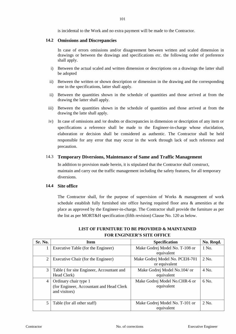
101
Contractor No. of corrections Executive Engineer
is incidental to the Work and no extra payment will be made to the Contractor.
14.2 Omissions and Discrepancies
In case of errors omissions and/or disagreement between written and scaled dimension in
drawings or between the drawings and specifications etc. the following order of preference
shall apply.
i) Between the actual scaled and written dimension or descriptions on a drawings the latter shall
be adopted
ii) Between the written or shown description or dimension in the drawing and the corresponding
one in the specifications, latter shall apply.
ii) Between the quantities shown in the schedule of quantities and those arrived at from the
drawing the latter shall apply.
iii) Between the quantities shown in the schedule of quantities and those arrived at from the
drawing the latte shall apply.
iv) In case of omissions and /or doubts or discrepancies in dimension or description of any item or
specifications a reference shall be made to the Engineer-in-charge whose elucidation,
elaboration or decision shall be considered as authentic. The Contractor shall be held
responsible for any error that may occur in the work through lack of such reference and
precaution.
14.3 Temporary Diversions, Maintenance of Same and Traffic Management
In addition to provision made herein, it is stipulated that the Contractor shall construct,
maintain and carry out the traffic management including the safety features, for all temporary
diversions.
14.4 Site office
The Contractor shall, for the purpose of supervision of Works & management of work
schedule establish fully furnished site office having required floor area & amenities at the
place as approved by the Engineer-in-charge. The Contractor shall provide the furniture as per
the list as per MORT&H specification (fifth revision) Clause No. 120 as below.
LIST OF FURNITURE TO BE PROVIDED & MAINTAINED
FOR ENGINEER’S SITE OFFICE
Sr. No. Item Specification No. Reqd.
1 Executive Table (for the Engineer) Make Godrej Model No. T-108 or
equivalent 1 No.
2 Executive Chair (for the Engineer) Make Godrej Model No. PCEH-701
or equivalent
2 No.
3 Table ( for site Engineer, Accountant and
Head Clerk)
Make Godrej Model No.104/ or
equivalent
4 No.
4 Ordinary chair type 1
(for Engineer, Accountant and Head Clerk
and visitors)
Make Godrej Model No.CHR-6 or
equivalent 6 No.
5 Table (for all other staff) Make Godrej Model No. T-101 or
equivalent 2 No.

102
Contractor No. of corrections Executive Engineer
6 Ordinary chair Type II
(for all other staff and visitors)
Make Godrej Model No.CHR-6 or
equivalent
2 No
7 Steel Cupboard
1980 mm x 915 mm x 485mm
Make Godrej Model No.1 Store wel
plain or equivalent
4 No.
8 Steel Cupboard
1270 mm x 765mm x 440mm
Make Godrej Model Minor plain or
equivalent
4 No.
9 Racks – 5 Tier
1800 mm x 900 mm x 375 mm
Made of slotted angles and M.S.
sheets of Godrej make
4 No.
10 Water Cooler Standard Make 1 No.
11 Air Cooler Standard Make 4 No.
12 Ceiling Fans 1400 mm size Ceiling fan shall be of approved 6 No.
13 Computer with Laser Printer Dual Core -2 with all latest Hard
ware
2 No.
14.4 (A) FACILITIES.
14) Contractor should provide at his own cost, temporary site office in the form of A.C.Porta
cabin with all required furniture cupboards etc including two computer, with internet facility
colour printer, scanner for Govt. Engineers which will belong to contractor , after completion
of project contractor may take out his property at his own.
15) During construction necessary precaution should be taken by contractor for security of the plot
from enchorment dumping of debris etc..
16) Contractor should provide at his own cost, CCTV Camera system with 24 hour recording and
internet facility.. All required access and password should provided to MMB officials for
monitoring project activities.
For road and bridge works the site office will have to be established on Work Site only.
14.5 Laboratory for Testing
The Contractor shall for the purpose of testing the materials establish a field laboratory
of adequate floor area as approved by Engineer-in-charge. The Contractor shall
provide all equipments and amenities as per the details mentioned in MORT& H
specification clause No. 121.3.1
Note: The field laboratory shall either be established at plant Site or as directed by
Engineer-in-Charge.
14.6 The Contractor will make arrangements to carry out various tests in the field
laboratory established for this purpose. The 70% sample could be tested at the field
laboratory and 30% samples shall be got tested in the Government laboratory or
laboratory approved by the Engineer- in-charge. The charges of testing the material in
Government or Government approved laboratory or recognized laboratory approved
by Engineer- in-charge shall be borne by the Contractor only.
14.7 The material for which test can not be carried out at the field laboratory shall be tested
at the Government laboratory approved by the Engineer- in-charge. The material
which can not be tested at Government laboratory shall be tested at the recognized
laboratory approved by the Engineer- in-charge in presence of the Engineer- in-charge
or his authorized representative.
15. Materials for use on Work
15.1 General
15.1.1 The Contractor shall make his own independent investigations into the availability as
well as suitability of the various materials required for construction.
15.1.2 The Contractor will have to make his own arrangement for procuring quarries or
quarry permits. Necessary assistance for this will be extending by the Department if

103
Contractor No. of corrections Executive Engineer
desired.
15.1.3 All the material required for construction of work shall be brought by the Contractor at
his own cost. The samples of material to be procured shall be got approved from the
Engineer- in-charge. The material as per approved samples shall only be procured.
The Contractor shall submit periodically as well as on completion of work, an account
of all materials brought by the Engineer- in-charge. The Contractor shall also furnish
monthly account of materials. A separate register shall be maintained on Site for
recording daily item wise receipt and consumption of cement, steel and bitumen used
by him and item wise consumption of other materials used. This register shall be
signed daily by the Contractor or his representative and representative of Engineer- in-
charge.
15.1.5 The Contractor shall not transfer any material once brought at Work site without prior
written permission from Engineer- in-charge and for bonafied reasons only.
15.1.6 Testing of all construction material shall be carried out as per required frequency and
MORT& H specification clause No.903.3.1, 1000, 1600, 1700, 1900, 2200, 2700.
15.1.7 In case the materials brought by the Contractor become surplus owing to the change in
the design for the work the materials should be taken back by the Contractor at his
own cost after prior permission of the Engineer- in-charge.
15.1.8 The charges for conveyance of materials from the place of delivery to the site of work
and the actual spot on work site shall be entirely borne by the Contractor. No claim on
this account shall be entertained.
15.2 Cement
15.2.1 The Contractor shall make his own arrangement for procurement of Cement required
for the Work. The Cement shall be OPC Grade-43 conforming to IS 8222. The supply
of cement shall be of brand approved by Engineer-in-Charge. The testing of cement so
procured shall be carried out as per the frequency as mentioned in MORT & H
specification clause No.1000. The testing charges will have to be borne by the
Contractor.
15.2.2 Cement to be used on Works shall be as fresh as possible and shall be used as per I.S.
Code from the date of manufacture.
15.3 Bitumen - Deleted
15.4 Bitumen’s Mixes - Deleted
15.5 Cement Concrete
15.5.1 The Contractor shall carry out all preliminary tests to work out grading and
proportioning of aggregates in order to obtain and maintain uniform quality of work.
The Contractor shall supply all materials, labour for preparing and testing samples as
required by the Engineer-in-charge Unless otherwise specified in the detailed item
wise specifications. The concrete cube shall be tested as per CI. 1716.2.4 The
contractor shall also make field arrangements for slump test and bulkage of sand. The
frequency of test as per Ministry’s specification. The cubes shall be got tested as
approved laboratory and the test results shall conform to the M.O.R.R.T. & H
specifications (4th Revision) Clause No.1716.2.6 or as laid down in the specifications.
15.2.2 a) All concrete shall be machine mixed, either in a concrete mixer or in a batching and
mixing plant as per specifications. No. hand mixing will be permitted. The mixer or
the plant shall be at an approved location considering the proportions of the mixes and
transportation means available with the Contractor.
b) Fro Controlled or High grade concrete, the grading of aggregate shall be got

104
Contractor No. of corrections Executive Engineer
approved from the Engineer-in-Charge. The correct proportions and the total quantity
of water for the mix will be determined b means of preliminary test and shall be got
approved from the Executive –in – Charge. However, such approval does not relive the
Contractor from his responsibility regarding the minimum strength requirements for
Work. Test shall be taken in accordance with relevant codes and specifications
15.5.3 Concrete shall meet with any other requirements as specified on the drawings or as
directed be Engineer-in-charge. Additional requirements as regards overall limits of
deleterious substances in concrete shall be as per M.O.R.T. & H specifications (Fifth
Revision) Clause No.1704.4
15.5.4 The Concrete shall be mechanically vibrated for proper water from 28 days after the
time of its placement or as may be directed by the Engineer-in-charge. Alternate
method of curing viz. steam curing, use of curing compound shall be got approved
from Engineer-in-charge in writing before its application.
15.3 Cement- for B.C.
Cement to be used for the work shall comply of the following with the prior approval
of Engineer- in-charge. Ordinary Portland Cement 43 grade only confirming to IS:
8112 shall be used in the item of B.C. as a filler and shall be from the same factory.
Independent testing of cement used shall be done by the Contractor at site and in the
laboratory approved by the Engineer- in-charge before use. Any cement with lower
quality than those shown in manufacture’s certificate shall be debarred from use.
16 Patented devices
Whether the Contractor desired to use any designed device, material or process
covered by letter of patent or copy right, the right for such use shall be secured by
suitable legal arrangement and arrangement with patent owner and the copy of their
agreement shall be field with the Engineer- in-charge if so desired by the latter.
17. Rejection of Material
17.1 Any stock or batch of material (s) of which sample(s) does not conform to the
prescribed test and quality shall be rejected by the Engineer- in-charge or his
representative and such material(s) shall be removed from the site by the Contractor at
his own cost. Such rejected material shall not be made acceptable by any
modifications.
17.2 Material not corresponding in character and quality with approved samples will be
rejected by the Engineer- in-charge or his representative and shall be removed form
site by the Contractor at his own cost.
18. Stacking, Storage & Guarding of Materials
18.1.1 The stacking and storage of materials at site at shall be in such a manner as to prevent
deterioration or intrusion of foreign matter and to ensure the preservation of their
quality, properties and fitness for the work. Suitable precautions shall be taken by the
Contractor to protect against atmospheric actions, fire and other hazard.
18.1.2 The materials likely to be carried away by wind shall be stored in suitable stores or
with suitable barricades and where there is likelihood of subsidence of soil; heavy
materials shall be stored on paved platforms. Suitable separating barricades and
enclosures as directed by Engineer- in-charge shall be provided to separate various
materials brought by Contractor.
18.2 The Contractor shall at his own expenses, engage watchmen for guarding the
materials, plant, machinery and the work during day and night against any pilferage or
damage and also for prohibiting trespassers.
18.3 No materials brought to the site shall be removed from the site without the prior
approval of the Engineer- in-charge.

105
Contractor No. of corrections Executive Engineer
18.4 All constructional plant, provided by the Contractor shall, when brought on the site, be
deemed to be exclusively intended for the construction and the Contractor shall not
remove the same or any part thereof (save for purpose of moving it from on part of the
site to another) without the consent in writing of the Engineer- in-charge who shall
record the reasons for withholding the consent.
18.5 The materials shall not be stacked in place where it is liable to be damaged or lost due
to traffic passing over or to be washed away by rain or floods, to be buried under the
land slide etc. or ship down on embankment or hill side etc. No claims for any loss
due to these and similar causes will be entertained.
18.6 Before stacking, the materials shall be free from all earth, rubbish, vegetable matter
and other extraneous substance and in the case of metal, screened to gauge, if so
directed when ready. Ir shall be collected/ stacked entirely clear of the roadway, on
ground, which has been cleaned of vegetation and leveled. On high banks, ghat roads
etc. where it may not be practicable to stack it entirely clear of the road way, it may be
stacked with permission of the Engineer- in-charge, on berms in such a way as to
cause minimum danger and obstruction to the traffic or as may be directed by him.
18.7 The material brought by the Contractor and dismantled material if any shall be so
stacked as to allow the traffic on National Highway in smooth and undisturbed manner
without any hindrances and as directed by Engineer- in-charge that the material
stacked along the road side is causing hindrances to the through traffic or blocking the
required working area then the such material will be ordered to be removed or shifted
at the place directed by the Engineer- in-charge at the cost of the Contractor.
19 Supervision and Inspection of Work
19.1 Supervision
19.1.1 The Contractor shall either himself supervise the execution of the Works or shall
appoint the competent agent approved by the Engineer- in-charge to act on his behalf.
The intimation of appointment of such agent shall be communicated in writing to the
Engineer- in-charge within 10 days of the date of issue of notice to proceed with the
work.
19.1.2. Orders given to the Contractor’s agent shall be considered to have the same force as if
these had been given to the Contractor himself. If the Contractor fails to appoint
suitable agent as directed by the Engineer- in-charge the Engineer- in-charge shall
have full power to suspend the execution of the work until such date a suitable agent is
appointed and the Contractor shall be responsible for the delay so cause to the Works
and Contractor shall not be entitled for any compensation on this behalf.
19.2 Inspection
19.2.1 The Engineer- in-charge and or any person authorized by him shall at all times have
access to the Works or part thereof and to all Workshops and places (including
required documents) where work is being prepared or from where materials,
manufactured articles or machinery are being obtained for the Works and the
Contractor shall offer every facility for and every assistance in or in obtaining the right
to such access.
19.2.2 The Contractor shall inform the Engineer- in-charge in writing when any portion of
the work is ready for inspection giving him sufficient notice to enable him to inspect
the same without affecting the further progress of the work.
19.2.3. The Contractor shall provide at his own cost necessary ladders and such arrangements
as are considered safe by the Engineer- in-charge for proper inspection of all parts of
the work.

106
Contractor No. of corrections Executive Engineer
19.2.4 The Contractor shall extend his full co-operation and make all necessary arrangement
when needed for carrying out inspection of the work or any part of the work by the
local representatives, M.L.A., M.P. and officers etc. No compensation shall be paid to
the Contractor on this account.
20 Measurement of Works
20.1 Initial Measurement for Record.
20.1.1 Where for proper measurement of the work, it is necessary to have an initial set of
levels or other measurement taken, the same as recorded in the authorized field book
or Measurement book of Government by the Engineer- in-charge or his authorized
representative will be signed by the Contractor who will be entitled to have a true
copy of same made at his cost.
20.1.2 Any failure on the part of the Contractor to get such level etc. recorded before starting
the work will render him liable to accept the decision of the Engineer- in-charge as to
the basis of taking measurements.
20.1.3. The Contractor will not cover any work which will render its subsequent measurement
difficult or impossible without first getting the same jointly measured by himself and
the authorized representative of the Engineer- in-charge. The record on the
Government side of such measurement will be signed by the Contractor and he will be
entitled to have a true copy of the same made at his cost.
20.2 Intermediate and Final Measurements
The General rules for intermediate & final measurement for payment shall conform to
the provision mentioned in clause 113 of MORT&H specifications 5th Revision
21 Completion of Work
21.1 The Contractor after completion of work shall clean the site of all debris and remove
all unused materials other than those supplied by the department and all plant and
machinery, equipment, tools etc. belonging to him within one month from the date of
completion of the work, or otherwise the same will be removed by the department at
his cost o disposed of as per departmental procedure. In case the material is disposed
off by department, the sale proceeds will be credited to the Contractors account after
deducting he cost of sale incurred. However no claim of Contractor regarding the price
of amount credited will be entertained afterwards.
21.2 The work shall not be considered to have been completed in accordance with the terms
of the contract until the Engineer- in-charge shall have certified in writing to that
effect. No approval of material or workmanship or approval of part of work during the
progress of execution shall blind the Engineer- in-charge or in any way prevent him
from even rejecting the work which is claimed to be completed and to suspend the
issue of his certificate of completion until such alteration and modification or
reconstruction have been effected at the cost of the Contractor as shall enable him to
certify that the work has been completed to his satisfaction.
21.3 After the work is completed the Contractor shall give notice of such completion to the
Engineer- in-charge and within 30 days of receipt of such a notice the Engineer- in-
charge shall inspect the work and if there is no defect in the work, shall furnish the
Contractor with certificate indicating the date of completion. However, if there are any
defects which in the opinion of the Engineer- in-charge are rectifiable he shall inform
the Contractor the defects noticed. The Contractor after rectification of such defects
shall then inform the Engineer- in-charge and Engineer- in-charge on his part shall
inspect the work and issue the necessary completion certificate within 30 days if the
defects are rectified to his satisfaction and if not he shall inform the Contractor
indicating defects yet to be rectified. The time cycle as above, shall continue.
21.4 In case defects noticed by the Engineer- in-charge which in his opinion are not
rectifiable but otherwise work is acceptable at reduced payment, work shall be treated
as completed. In such cases completion certificate shall be issued by the Engineer- in-
107
Contractor No. of corrections Executive Engineer
charge within 30 days indicating the unrectifiable defects for which specified
reduction in payment is being made by him.
21.5 The completion certificate shall not be issued until the site is thoroughly cleaned and
cleared off all unwanted material
21.6 On completion of work in all respects necessary certificate will be issued by the
Engineer- in-charge and defect liability period will be counted from the date of issue
of such certificate.
21.7 Completion drawing
The Contractor shall submit to the Engineer- in-charge within 2 (two) months of
actual completion “Completion Drawing” as specified below and operation and
maintenance instruction for the whole of the work.
These drawings shall be accurate and correct in all respect and shall be shown to and
approved by the Engineer- in-charge. For “Completion” drawing 2 (Two) prints and
one polyester film of quality approved by the Engineer- in-charge or his representative
shall be supplied.
21.8 Supply of Color Record Photographs and Albums
21.8.1 The Contractor shall arrange to take colour photograph at various stages / faces of the
Works including interesting and novel features of the work as desired by the Engineer-
in-charge needed for authentic documentation as desired. The photographs shall be of
acceptable quality and they shall be taken by professionally competent photographer
with camera having the facility to record the date of photographs taken in the prints
and negative /C.D. The Contractor shall supply two color prints of each of the
photographs taken to the standard 4’’ x 6’’ size mounted in albums of acceptable
quality along with C.D. Also the negative in 35mm. size for each photograph or in
C.D. shall be supplied. Each photograph in the album shall be suitably captioned. It
shall be considered as incidental to the work and no additional payment whatsoever
will be made for the same.
21.8.2. Videography
Contractor shall supply video films/video C.D./Digital Photograph before stating of
work, during execution and completed work of important activities of the work as
directed by Engineer- in-charge during currency of the project and editing them to a
video film / CD of playing time not less than 90 minutes and up to 180 minutes as
directed by Engineer- in-charge. Such as film shall be suitably narrative and titled
indicating chainage, activities. The video cassette / CD shall be of acceptable quality
and shall be capable of producing colored pictures. This is incidental to work and no
payments shall be made for the same.
22 Handing over of Work
22.1 All the work and material before finally taken over by Government will be the entire
liability of the Contractor for guarding, maintaining and making good any damaged of
any magnitude. Interim payments made for such work will not alter this position.
22.2 The handing over by the Contractor and taking over by the Engineer- in-charge or his
authorized representative will always are writing of which copies will go to the Engineer-
in-charge and the Contractor. It is however understood that before taking over such Works
Government will not put it into regular use as distinct from casual or incidental one,

108
Contractor No. of corrections Executive Engineer
except as specifically mentioned elsewhere in this contract, or as mutually agreed to.
22.3 Indemnity
The Contractor shall indemnify the Government against all action, suits, claims and
demands brought or made against it in against of anything done or committed to be
done by the Contractor in execution of or in connection with the work of this contract
and against any loss or damages to the Government in consequences to any action or
suit being brought against the Contractor for anything done or committed to be done
in the execution of the work of this contract. The Government may, at its discretion
and entirely at the cost of Contractor, defend such sit either jointly with the Contractor
or single, in case the latter chooses not to defend the case.
23 Amenities to Department - Deleted
24 Maintenance During Contract Period
24.1.1 The section of road in which the work lies shall be deemed to be handed over on Date
of Work Order (in respect of repairs to pot holes formed during agreement period).
Notwithstanding whether the agency has tackled some length or otherwise the
responsibility of maintaining the complete length covered under the scope of work
will be with the agency only. The agency shall get the potholes filled as per the
directions of the Engineer- in-charge and ensure that the road remaining traffic
worthy. The Contractor shall maintain the finished surface of the road for a period up
to Defect Liability Period without any extra cost to the Government irrespective of the
designs standards and specifications and actual traffic etc.
24.1.2 All damages during execution shall be made good by the Contractor at his own cost.
He will be responsible for any damages to the road surface including B.T. surface in
rainy seasons and during construction and guaranteed maintenance period and no
separate payment will be made for restoring such damages.
24.1.3. Defective work is liable to rejected at any stage. The Contractor on no account shall
refuse to rectify the defects merely on reasons that further work has been carried out.
No extra payment shall be made for such rectification.
24.2 During Defect Liability Period
24.2.1 Defect Liability shall mean the obligation of Contractor to undertake the following
Works as per the specifications, to the satisfaction of Engineer- in-charge.
a. To complete any work which is outstanding in date stated in Taking Over
Certificate within a stipulate d time as directed by Engineer- in-charge and
b. To execute all work required to remedy defects or damage as may be as notified
by Engineer- in-charge on or before the expiry date of the defects notified by the
Engineer- in-charge for the Works or sections as the case may be. If a defect appears
or damage occurs the Contractor shall be notified accordingly by the Engineer- in-
charge or his authorized representative on his behalf. The Contractor shall remedy the
defects/ damages notified to him within a time period as stipulated by Engineer- in-
charge. If the Contractor fails to remedy/ rectify the defects or damages by this
notified date, it shall be executed at the risk and cost of Contractor.
24.2.2 The Contractor has to commence the remedying work as soon as possible and in any
case not later the 3 days of its communication by the Engineer- in-charge and
complete the same within 7 days maximum or in a time period as directed by
Engineer- in-charge. In case the Contractor fails to start the remedying work within
above specified period, the department will take necessary action to carry out such
Works at the risk and cost of the Contractor and the amount so incurred will be
recovered from the Contractor from any such amount payable to the Contractor by the
Government or though the deposit available with the department and even as recovery

109
Contractor No. of corrections Executive Engineer
of land revenues if necessary.
24.3 The agency will have to make all necessary arrangements for smooth flow of traffic
till the time the remedying rectification work is completed or also this will be done by
the department at the risk and cost of Contractor. The Contractor’s liability of
maintaining the road to the required specifications will commence right from the date
of issue of notice to proceed with the work till the expiry of defect liability period. The
extends to the untracked portion of work also.
110
Contractor No. of corrections Executive Engineer
24.4 Visit of Contractor During Defect Liability Period
Contractor shall carry out one inspection in every 3 months during the first year after
completion of the work and carry minimum 2 inspections per year for the remaining 2
years of Defect Liability Period. However during rainy season the Contractor shall
undertake such an inspection every month till the monsoon is over. The inspection
shall be in the company of the representative of Engineer- in-charge. The defects
noticed during the inspections shall be recorded and signed by the Contractor and
representative of Engineer- in-charge. The Contractor shall rectify the defects if any,
within 7 days or such period as may be notified by the Engineer- in-charge.
25. Quality Control Tests: -The contractor shall at his own cost set up Laboratory
at site of work to carry out the testing of materials which are to be used for the
work. This laboratory shall be approved by the Engineer-in-charge. The testing
shall be done as per frequencies mentioned in the specification/additional
specification of each item of Schedule 'B'. The 30% of the test included in
Annexure 'A' (On Page No. 107) shall be carried out in Vigilance and Quality
Control Laboratory at the cost of contractor and balance 70% in the site
laboratory. The test which are not included in Annexure 'A' 50% test shall be
carried out each in Vigilance and Quality Control laboratory and site
laboratory. The frequency of testing of construction materials is mentioned in
Annexure-Bon Page No. 108 to 109

111
Contractor No. of corrections Executive Engineer
SECTION – 6
FORM OF BID

112
Contractor No. of corrections Executive Engineer
FORM OF BID #
Description of the Work :-Construction of Proposed Office Building on Plot No. C-47 'G'
Block at Bandra Kurla Complex (BKC) Mumbai at Maharashtra Maritime Board.
Chief Executive Officer, Maharashtra Maritime Board, Indian Mercantile Chamber, 3rd floor, Ramjibhai Kamani Marg, Ballard Estate, Mumbai-400 001.
1. We offer to execute the works described above and remedy any defects therein in conformity with the
conditions of contract, specification, drawings, Bill of Quantities and Addenda for the sum(s)
of .....................................................................................................
2. We undertake, if our Bid is accepted, to commence the Works as soon as is reasonably possible after
the receipt of the Engineer’s notice to commence and to complete the whole of the Works comprised
in the Contract within the time stated in the document.
3. We agree to abide by this Bid for the period of 90 days from the date fixed for receiving the same and
it shall remain binding upon us and may be accepted at any time before the expiration of that period.
4. Unless and until a format Agreement is prepare and executed this Bid, together with your written
acceptance thereof, shall constitute a binding contract between us.
5. We understand that you are not bound to accept the lowest or any tender you may receive.
6. We accept the appointment of Shri. ........................................................ as the Dispute Review Expert.
(OR)
We do not accept the appointment of Shri. .......................... as the Dispute Review Expert and propose
instead that Shri. ........................ be appointed as Dispute Review Expert, whose BIO-DATA is
attached.
Dated this ....................... day of ......................... 20.................
Signature _______________________ in the capacity of _________duly authorised sign bids for and
on behalf of ...................................................................................................... (in block capitals or
typed)
Address
..........................................................................................................................................................
Witness
..........................................................................................................................................................
Address
........................................................................................................................................................
Occupation
...................................................................................................................................................
# Note-The bidder will submit this form online without his financial offer. The bidder shall fill the rates online
in the BOQ sheet provided in the e-tender portal only.
113
Contractor No. of corrections Executive Engineer
SECTION – 7
BILL OF QUANTITIES
Refer Part-II

114
Contractor No. of corrections Executive Engineer
SECTION – 8
SECURITIES AND OTHER FORMS
115
Contractor No. of corrections Executive Engineer
SECTION – 9
DRAWINGS
Refer Part II
116
Contractor No. of corrections Executive Engineer
DOCUMENTS TO BE FURNISHED BY THE BIDDER
(Attached)
- 1 -
Contractor No. of corrections Executive Engineer
STANDARD BIDDING DOCUMENT
PROCUREMENT OF CIVIL WORKS
PART-II
COMPLETE BIDDING DOCUMENT
NAME OF
WORK :
Construction of Proposed Office
Building on Plot No. C-47 'G' Block
at Bandra Kurla Complex (BKC)
Mumbai for Maharashtra Maritime
Board
E-TENDER
B-II TENDER FORM

- 2 -
Contractor No. of corrections Executive Engineer
GOVERNMENT OF MAHARASHTRA
AGREEMENT NO---------------
NATIONAL COMPETITIVE BIDDING
(CIVIL WORKS)
Name of work : Construction of Proposed Office Building on Plot No. C-47 'G' Block at Bandra Kurla Complex (BKC) Mumbai at Maharahstra Maritime Board
Tender Issue Date : Date. 05.03.2018 at 10.00 hrs
Time and date of pre-bid
conference
: Date. 26.03.2018 at 15.00 hrs, Maharashtra Maritime
Board, Indian Mercantile Chamber, 3rd
floor, Ramjibhai Kamani Marg, Ballard Estate, Mumbai-400 001.
Opening Date
(If possible)
: Date. 20.04.2018 at 12.00 hrs Maharashtra Maritime
Board, Indian Mercantile Chamber, 3rd
floor, Ramjibhai Kamani Marg, Ballard Estate, Mumbai-400 001
Officer inviting bids Chief Executive Officer, Maharashtra Maritime Board, Indian Mercantile Chamber, 3rd floor, Ramjibhai Kamani Marg, Ballard Estate, Mumbai-400 001
- 3 -
Contractor No. of corrections Executive Engineer
SECTION 1 – INSTRUCTIONS TO BIDDERS (ITB)
Refer SECTION 1
Of
PART I
COMPLETE BIDDING DOCUMENT
- 4 -
Contractor No. of corrections Executive Engineer
SECTION – 3
CONDITIONS OF CONTRACT
Refer SECTION - 3
Of
PART I
COMPLETE BIDDING DOCUMENT
- 5 -
Contractor No. of corrections Executive Engineer
SECTION – 4
CONTRACT DATA
Refer SECTION - 4
Of
PART I
COMPLETE BIDDING DOCUMENT

- 6 -
Contractor No. of corrections Executive Engineer
SECTION – 5
TECHNICAL SPECIFICATION
Refer SECTION - 5
Of
PART I
COMPLETE BIDDING DOCUMENT
- 7 -
Contractor No. of corrections Executive Engineer
SECTION – 6
FORM OF BID

- 8 -
Contractor No. of corrections Executive Engineer
FORM OF BID
Description of the Work :- Construction of Proposed Office Building on Plot No. C-47 'G' Block at
Bandra Kurla Complex (BKC) Mumbai at Maharahstra Maritime Board
Executive Engineer, Maharashtra Maritime Board,
Mumbai
1. We offer to execute the works described above and remedy any defects therein in conformity with the
conditions of contract, specification, drawings, Bill of Quantities and Addenda for the sum(s)
of .....................................................................................................
2. We undertake, if our Bid is accepted, to commence the Works as soon as is reasonably possible after
the receipt of the Engineer’s notice to commence and to complete the whole of the Works comprised
in the Contract within the time stated in the document.
3. We agree to abide by this Bid for the period of 120 days from the date fixed for receiving the same
and it shall remain binding upon us and may be accepted at any time before the expiration of that
period.
4. Unless and until a format Agreement is prepare and executed this Bid, together with your written
acceptance thereof, shall constitute a binding contract between us.
5. We understand that you are not bound to accept the lowest or any tender you may receive.
6. We accept the appointment of Shri. ........................................................ as the Dispute Review Expert.
(OR)
- 9 -
Contractor No. of corrections Executive Engineer
We do not accept the appointment of Shri. .......................... as the Dispute Review Expert and propose
instead that Shri. ........................ be appointed as Dispute Review Expert, whose BIO-DATA is
attached.
Dated this ....................... day of ......................... 20.................
Signature _______________________ in the capacity of _________duly authorised sign bids for and
on behalf of ...................................................................................................... (in block capitals or
typed)
Address
..........................................................................................................................................................
Witness
..........................................................................................................................................................
Address
........................................................................................................................................................
Occupation
...................................................................................................................................................
# Note-The bidder will submit this form online without his financial offer. The bidder shall fill the rates online
in the BOQ sheet provided in the e-tender portal only.

- 10 -
Contractor No. of corrections Executive Engineer
SECTION – 7
BILL OF QUANTITIES

- 11 -
Contractor No. of corrections Executive Engineer
BILL OF QUANTITIES
Preamble
1. The Bill of Quantities shall be read in conjunction with the Instructions to Bidders, Conditions of
Contract, Technical Specifications and Drawings.
2. The quantities given in the Bill of Quantities are estimated and provisional, and are given to provide a
common basis for bidding. The basis of payment will be the actual quantities of work ordered and
carried out, as measured by the Contractor and verified by the Engineer and valued at the rates and
prices tendered in the priced Bill of Quantities, where applicable and otherwise at such rates and
prices as the Engineer may fix within the terms of the Contract.
3. The rates and prices tendered in the priced Bill of Quantities shall, except in so far as it is otherwise
provided under the Contract, include all constructional plant, labour, supervision, materials, erection,
maintenance, insurance, profit, taxes and duties, together with all general risks, liabilities and
obligations set out or implied in the Contract.
4. The rates and prices shall be quoted entirely in Indian Currency.
5. A rate or price shall be entered against each item in the Bill of Quantities, whether quantities are
stated or not. The cost of items against which the Contractor has failed to enter a rate or price shall
deemed to be covered by other rates and prices entered in the Bill of Quantities.
6. The whole cost of complying with the provisions of the Contract shall be included in the terms
provided in the priced Bill of Quantities and where no items are provided the cost shall be deemed to
be distributed among the rates and prices entered for the related Items of Work.
7. General directions and descriptions of work and materials are not necessarily repeated or summarized
in the Bill of Quantities. References to the relevant sections of the contract documentation shall be
made before entering rates or prices against each item in the Bill of Quantities.
8. The method of measurement of completed items of work for payment shall be in accordance with the
specification for Road and Bridge Works published by the Ministry of Road Transport & Highways,
(Vth
Revision) April 2013.
9. Errors will be corrected by the Employer for any arithmetic errors pursuant to Clause 29 of the
Instructions to Bidders.
10. Rock is defined as all materials which, in the opinion of the Engineer, require blasting or the use of
metal wedges and sledge hammers or the use of compressed air drilling for its removal and which
cannot be extracted by ripping with a tractor of at least 150 kw with a single rear mounted heavy duty
ripper.
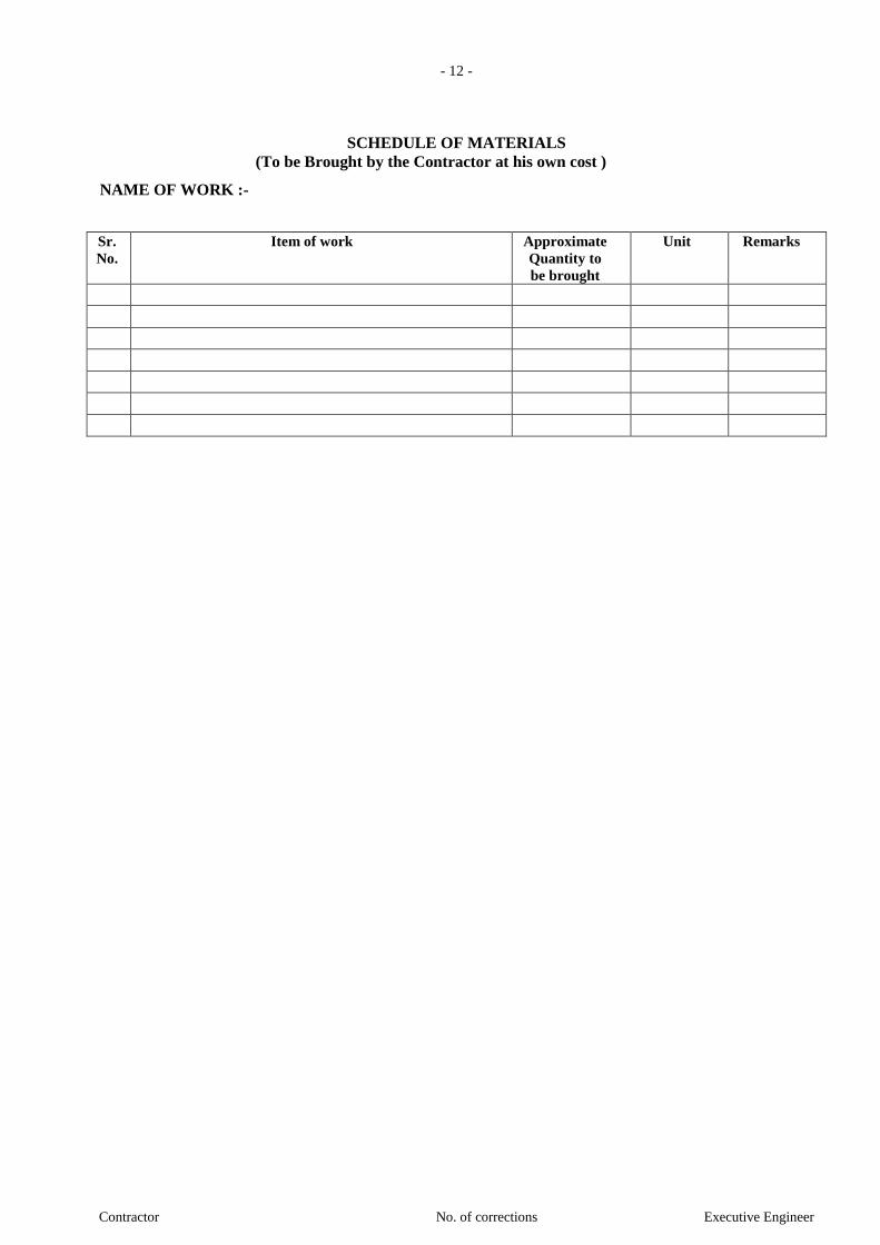
- 12 -
Contractor No. of corrections Executive Engineer
SCHEDULE OF MATERIALS
(To be Brought by the Contractor at his own cost )
NAME OF WORK :-
Sr.
No.
Item of work Approximate
Quantity to
be brought
Unit Remarks
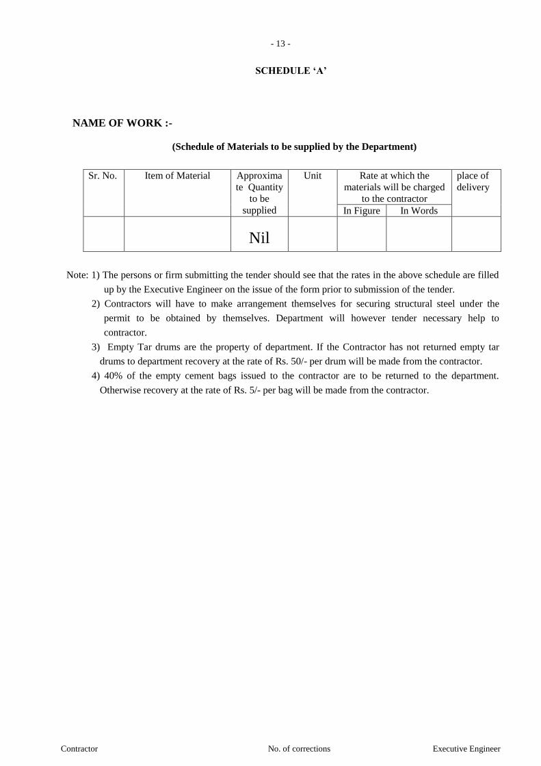
- 13 -
Contractor No. of corrections Executive Engineer
SCHEDULE ‘A’
NAME OF WORK :-
(Schedule of Materials to be supplied by the Department)
Sr. No. Item of Material Approxima
te Quantity
to be
supplied
Unit Rate at which the
materials will be charged
to the contractor
place of
delivery
In Figure In Words
Nil
Note: 1) The persons or firm submitting the tender should see that the rates in the above schedule are filled
up by the Executive Engineer on the issue of the form prior to submission of the tender.
2) Contractors will have to make arrangement themselves for securing structural steel under the
permit to be obtained by themselves. Department will however tender necessary help to
contractor.
3) Empty Tar drums are the property of department. If the Contractor has not returned empty tar
drums to department recovery at the rate of Rs. 50/- per drum will be made from the contractor.
4) 40% of the empty cement bags issued to the contractor are to be returned to the department.
Otherwise recovery at the rate of Rs. 5/- per bag will be made from the contractor.

- 14 -
Contractor No. of corrections Executive Engineer
BILL OF QUANTITIES
Schedule “B”
Sl. No.
Description of Item Quantity may be more or
less
Unit Rate Amount
In Figure In Words 1 2 3 4 5 6 7
1.1.1 Item No.1: Excavation for foundation in earth, soil of all types, sand, gravel and soft murum, including removing the excavated material up to a distance of 50 m. beyond the building area and stacking and spreading as directed, dewatering, preparing the bed for the foundation and necessary back filling, ramming, watering including shoring and strutting etc. complete. (Lift upto 1.5 m.)
5478.78 Cum
1.1.2 Excavation for foundation in earth, soils of all types, sand, gravel and soft murum, including removing the excavated material upto a distance of 50 metres beyond the building area and stacking and spreading as directed, dewatering, preparing the bed for the foundation and necessary back filling, ramming, watering including shoring and strutting etc. complete. (Lift from 1.5m to 3.0m)
5308.91 Cum
1.1.3 Same as item No. 1.1.2 - Lift from 3.00m to 4.50m
5265.22 Cum
1.1.4 Same as item No. 1.1.2 - Lift from 4.50m to 6.00m
5265.22 Cum
1.1.5 Same as item No. 1.1.2 - Lift from 6.00m to 7.50m
2632.61 Cum
1.1.6 Same as item No. 1.1.2 - Lift from 7.50m to 9.00m
1842.83 Cum
1.1.7 Same as item No. 1.1.2 - Lift from 9.00m to 10.50m
1316.30 Cum
1.1.8 Same as item No. 1.1.2 - Lift from 10.50m to 12.00m
50.00 Cum
1.1.9 Same as item No. 1.1.2 - Lift from 12.00m to 13.50m
50.00 Cum
1.2.1 Excavation for foundation in Soft rock and old cement or lime masonry foundations including removing the excavated material upto a distance of 50 metres beyond the building area and stacking as directed, including dewatering, preparing the bed for the foundation and necessary back filling with available earth /murum, ramming, watering including shoring and strutting etc. complete (lift upto 1.5m)
50.00 Cum
1.2.2 Excavation for foundation in Soft rock and old cement or lime masonry foundations including removing the excavated material upto a distance of 50 metres beyond the building area and stacking as directed, including dewatering, preparing the bed for the foundation and necessary back filling with available earth/murum, ramming ,watering including shoring and strutting etc. complete. (Lift from 1.5m To 3.0 m.)
50.00 Cum
1.2.3 Same as item No. 1.1.2 - Lift from 3.00m to 4.50m
50.00 Cum
1.2.4 Same as item No. 1.1.2 - Lift from 4.50m to 50.00 Cum

- 15 -
Contractor No. of corrections Executive Engineer
Sl. No.
Description of Item Quantity may be more or
less
Unit Rate Amount
In Figure In Words 1 2 3 4 5 6 7
6.00m
1.2.5
Same as item No. 1.1.2 - Lift from 6.00m to 7.50m
789.78 Cum
1.2.6 Same as item No. 1.1.2 - Lift from 7.50m to 9.00m
526.52 Cum
1.2.7 Same as item No. 1.1.2 - Lift from 9.00m to 10.50m
526.52 Cum
1.2.8 Same as item No. 1.1.2 - Lift from 10.50m to 12.00m
25.00 Cum
1.2.9 Same as item No. 1.1.2 - Lift from 12.00m to 13.50m
25.00 Cum
1.3.1 Excavation for foundation in Hard rock by chiselling, wedging, line drilling, etc. including trimming and levelling the bed, removing the excavated material upto a distance of 50 metres beyond the building area stacking as directed, dewatering and back filling with available earth/ murum watering, ramming etc. complete. (Lift upto 1.5 m).
50.00 Cum
1.3.2 Same as item No. 1.3.1 - Lift from 1.50m to 3.00m
50.00 Cum
1.3.3 Same as item No. 1.3.1 - Lift from 3.00m to 4.50m
50.00 Cum
1.3.4 Same as item No. 1.3.1 - Lift from 4.50m to 6.00m
50.00 Cum
1.3.5 Same as item No. 1.3.1 - Lift from 6.00m to 7.50m
1842.83 Cum
1.3.6 Same as item No. 1.3.1 - Lift from 7.50m to 9.00m
2895.87 Cum
1.3.7 Same as item No. 1.3.1 - Lift from 9.00m to 10.50m
3422.39 Cum
1.3.8 Same as item No. 1.3.1 - Lift from 10.50m to 12.00m
2983.85 Cum
1.3.9 Same as item No. 1.3.1 - Lift from 12.00m to 13.50m
536.76 Cum
1.4 Providing preconstructional antitermite treatment as per I.S. 6313 (Part-I) to the soil along the external face of building by punching holes of 1.2 of 1.5 C.M. diametre about 30 -60 cm deep at 15 cm c/c as close to the wall as possible and to inject 0.5 percent of aldrin or clorophyrifos at the rate of 7.5 litres per hole and sealing the same with proper filling and covering 10 years guarantee on bond paper.
425.33 Sqm
1.5 Filling in plinth and floors with contractors material/brought from outside and approved by Engineer incharge in layers of 15 cm to 20 cm including watering and compaction etc. complete.(Murum filling at Basement 3 level)
2539.8 Cum
1.6 Providing dry/ trap/ granite/ quartzite/ gneiss rubble stone soling 15 cm to 20 cm thick including hand packing and compacting etc. complete.
364.17 Cum
1.7 Providing and fixing pressure relief pipes of 100 mm diametre of AC / PVC as per drawing for R.C.C Raft, galaries returns, abutments, wing wall etc complete.
655 Rmt
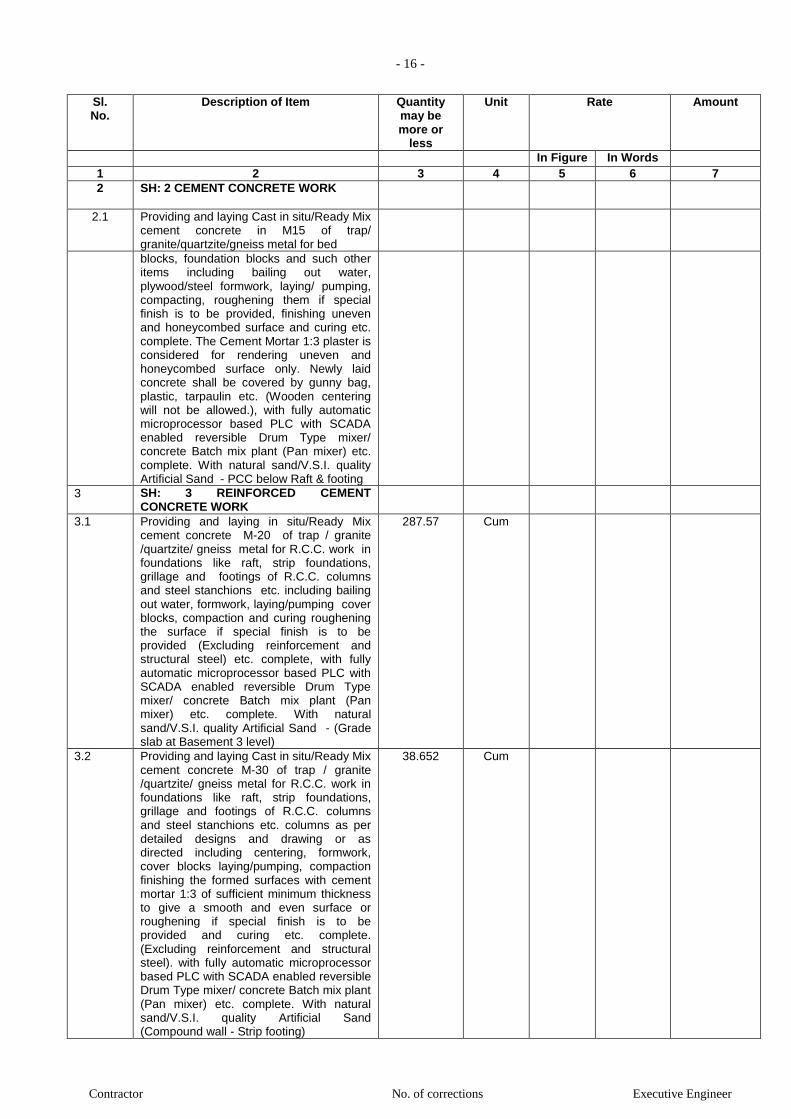
- 16 -
Contractor No. of corrections Executive Engineer
Sl. No.
Description of Item Quantity may be more or
less
Unit Rate Amount
In Figure In Words 1 2 3 4 5 6 7
2 SH: 2 CEMENT CONCRETE WORK
2.1 Providing and laying Cast in situ/Ready Mix cement concrete in M15 of trap/ granite/quartzite/gneiss metal for bed
blocks, foundation blocks and such other items including bailing out water, plywood/steel formwork, laying/ pumping, compacting, roughening them if special finish is to be provided, finishing uneven and honeycombed surface and curing etc. complete. The Cement Mortar 1:3 plaster is considered for rendering uneven and honeycombed surface only. Newly laid concrete shall be covered by gunny bag, plastic, tarpaulin etc. (Wooden centering will not be allowed.), with fully automatic microprocessor based PLC with SCADA enabled reversible Drum Type mixer/ concrete Batch mix plant (Pan mixer) etc. complete. With natural sand/V.S.I. quality Artificial Sand - PCC below Raft & footing
3 SH: 3 REINFORCED CEMENT CONCRETE WORK
3.1 Providing and laying in situ/Ready Mix cement concrete M-20 of trap / granite /quartzite/ gneiss metal for R.C.C. work in foundations like raft, strip foundations, grillage and footings of R.C.C. columns and steel stanchions etc. including bailing out water, formwork, laying/pumping cover blocks, compaction and curing roughening the surface if special finish is to be provided (Excluding reinforcement and structural steel) etc. complete, with fully automatic microprocessor based PLC with SCADA enabled reversible Drum Type mixer/ concrete Batch mix plant (Pan mixer) etc. complete. With natural sand/V.S.I. quality Artificial Sand - (Grade slab at Basement 3 level)
287.57 Cum
3.2 Providing and laying Cast in situ/Ready Mix cement concrete M-30 of trap / granite /quartzite/ gneiss metal for R.C.C. work in foundations like raft, strip foundations, grillage and footings of R.C.C. columns and steel stanchions etc. columns as per detailed designs and drawing or as directed including centering, formwork, cover blocks laying/pumping, compaction finishing the formed surfaces with cement mortar 1:3 of sufficient minimum thickness to give a smooth and even surface or roughening if special finish is to be provided and curing etc. complete. (Excluding reinforcement and structural steel). with fully automatic microprocessor based PLC with SCADA enabled reversible Drum Type mixer/ concrete Batch mix plant (Pan mixer) etc. complete. With natural sand/V.S.I. quality Artificial Sand (Compound wall - Strip footing)
38.652 Cum

- 17 -
Contractor No. of corrections Executive Engineer
Sl. No.
Description of Item Quantity may be more or
less
Unit Rate Amount
In Figure In Words 1 2 3 4 5 6 7
3.3 Providing and laying Cast in situ/Ready Mix cement concrete M-40 of trap / granite /quartzite/ gneiss metal for R.C.C. work in
Cum 1272.4
foundations like raft, strip foundations,
grillage and footings of R.C.C. columns and steel stanchions etc. columns as per detailed designs and drawing or as directed including centering, formwork, cover blocks, laying/pumping, compaction finishing the formed surfaces with cement mortar 1:3 of sufficient minimum thickness to give a smooth and even surface or roughening if special finish is to be provided and curing etc. complete. (Excluding reinforcement and structural steel).with fully automatic microprocessor based PLC with SCADA enabled reversible Drum Type mixer/ concrete Batch mix plant (Pan mixer) etc. complete. With natural sand/V.S.I. quality Artificial Sand
3.4 Providing and laying Cast in situ/Ready Mix cement concrete M-30 of trap / granite /quartzite/ gneiss metal for R.C.C. columns as per detailed designs and drawing or as directed including centering, formwork, cover blocks, laying/pumping, compaction finishing the formed surfaces with cement mortar 1:3 of sufficient minimum thickness to give a smooth and even surface or roughening if special finish is to be provided and curing etc. complete,(Excluding reinforcement and structural steel). with fully automatic microprocessor based PLC with SCADA enabled reversible Drum Type mixer/ concrete Batch mix plant (Pan mixer) etc. complete. With natural sand/V.S.I. quality Artificial Sand
Cum 36.203
3.5 Providing and laying Cast in situ/Ready Mix cement concrete M-40 of trap / granite /quartzite/ gneiss metal for R.C.C. columns as per detailed designs and drawing or as directed including centering, formwork, cover blocks, laying/pumping, compaction finishing the formed surfaces with cement mortar 1:3 of sufficient minimum thickness to give a smooth and even surface or roughening if special finish is to be provided and curing etc. complete,(Excluding reinforcement and structural steel).with fully automatic microprocessor based PLC with SCADA enabled reversible Drum Type mixer/ concrete Batch mix plant (Pan mixer) etc. complete. With natural sand/V.S.I. quality Artificial Sand
3.5.1 9th floor 191.93 Cum
3.5.2 10th floor 191.93 Cum
3.5.3 11th floor 191.93 Cum
3.5.4 12th floor & above 328.77 Cum
3.6 Providing and laying Cast in situ/Ready Mix cement concrete M-50 of trap / granite
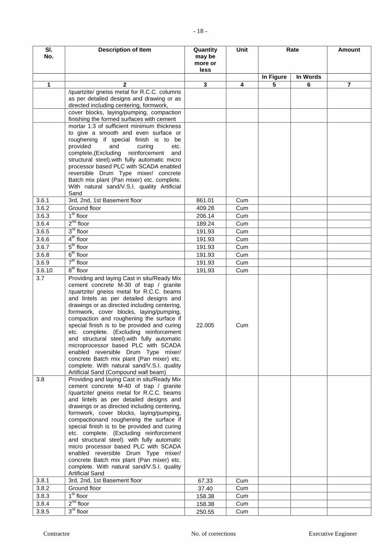
- 18 -
Contractor No. of corrections Executive Engineer
Sl. No.
Description of Item Quantity may be more or
less
Unit Rate Amount
In Figure In Words 1 2 3 4 5 6 7
/quartzite/ gneiss metal for R.C.C. columns as per detailed designs and drawing or as directed including centering, formwork,
cover blocks, laying/pumping, compaction finishing the formed surfaces with cement
mortar 1:3 of sufficient minimum thickness to give a smooth and even surface or roughening if special finish is to be provided and curing etc. complete,(Excluding reinforcement and structural steel).with fully automatic micro processor based PLC with SCADA enabled reversible Drum Type mixer/ concrete Batch mix plant (Pan mixer) etc. complete. With natural sand/V.S.I. quality Artificial Sand
3.6.1 3rd, 2nd, 1st Basement floor 861.01 Cum
3.6.2 Ground floor 409.28 Cum
3.6.3 1st floor 206.14 Cum
3.6.4 2nd
floor 189.24 Cum
3.6.5 3rd
floor 191.93 Cum
3.6.6 4th
floor 191.93 Cum
3.6.7 5th
floor 191.93 Cum
3.6.8 6th
floor 191.93 Cum
3.6.9 7th
floor 191.93 Cum
3.6.10 8th
floor 191.93 Cum
3.7 Providing and laying Cast in situ/Ready Mix cement concrete M-30 of trap / granite /quartzite/ gneiss metal for R.C.C. beams and lintels as per detailed designs and drawings or as directed including centering, formwork, cover blocks, laying/pumping, compaction and roughening the surface if special finish is to be provided and curing etc. complete. (Excluding reinforcement and structural steel).with fully automatic microprocessor based PLC with SCADA enabled reversible Drum Type mixer/ concrete Batch mix plant (Pan mixer) etc. complete. With natural sand/V.S.I. quality Artificial Sand (Compound wall beam)
22.005 Cum
3.8 Providing and laying Cast in situ/Ready Mix cement concrete M-40 of trap / granite /quartzite/ gneiss metal for R.C.C. beams and lintels as per detailed designs and drawings or as directed including centering, formwork, cover blocks, laying/pumping, compactionand roughening the surface if special finish is to be provided and curing etc. complete. (Excluding reinforcement and structural steel). with fully automatic micro processor based PLC with SCADA enabled reversible Drum Type mixer/ concrete Batch mix plant (Pan mixer) etc. complete. With natural sand/V.S.I. quality Artificial Sand
3.8.1 3rd, 2nd, 1st Basement floor 67.33 Cum
3.8.2 Ground floor 37.40 Cum
3.8.3 1st floor 158.38 Cum
3.8.4 2nd
floor 158.38 Cum
3.8.5 3rd
floor 250.55 Cum

- 19 -
Contractor No. of corrections Executive Engineer
Sl. No.
Description of Item Quantity may be more or
less
Unit Rate Amount
In Figure In Words 1 2 3 4 5 6 7
3.8.6 4th
floor 250.55 Cum
3.8.7 5th
floor 250.55 Cum
3.8.8 6th
floor 250.55 Cum
3.8.9 7th
floor 250.55 Cum
3.8.10 8th
floor 250.55 Cum
3.8.11 9th
floor 250.55 Cum
3.8.12 10th
floor 250.55 Cum
3.8.13 11th
floor 250.55 Cum
3.8.14 12th
floor & above 272.38 Cum 3.9 Providing and laying Cast in situ/Ready Mix
cement concrete M-30 of trap/ granite / quartzite/ gneiss metal for R.C.C. slabs and landings as per detailed designs and drawings including centering, formwork, cover blocks, laying/pumping, compaction finishing the formed surfaces with cement mortar 1:3 of sufficient minimum thickness to give a smooth and even surface or roughening if special finish is to be provided and curing etc. complete,(Excluding reinforcement and structural steel).with fully automatic microprocessor based PLC with SCADA enabled reversible Drum Type mixer/ concrete Batch mix plant (Pan mixer) etc. complete. With natural sand/V.S.I. quality Artificial Sand (OHT - Top/bottom slab)
28.37 Cum
3.10 Providing and laying Cast in situ/Ready Mix cement concrete M-40 of trap/ granite / quartzite/ gneiss metal for R.C.C. slabs and landings as per detailed designs and drawings including centering, formwork, cover blocks, laying/pumping, compactionfinishing the formed surfaces with cement mortar 1:3 of sufficient minimum thickness to give a smooth and even surface or roughening if special finish is to be provided and curing etc. complete,(Excluding reinforcement and structural steel).with fully automatic micro processor based PLC with SCADA enabled reversible Drum Type mixer/ concrete Batch mix plant (Pan mixer) etc. complete. With natural sand/V.S.I. quality Artificial Sand (Raft slab, floor slab & UGT/STP top/bot slab)
3.10.1 3rd, 2nd, 1st Basement floor 1498.99 Cum
3.10.2 Ground floor 558.76 Cum
3.10.3 1st floor 151.44 Cum
3.10.4 2nd
floor 151.44 Cum
3.10.5 3rd
floor 261.14 Cum
3.10.6 4th
floor 260.54 Cum
3.10.7 5th
floor 260.54 Cum
3.10.8 6th
floor 260.54 Cum
3.10.9 7th
floor 260.54 Cum
3.10.10 8th
floor 260.54 Cum
3.10.11 9th
floor 260.54 Cum
3.10.12 10th
floor 260.54 Cum
3.10.13 11th
floor 260.54 Cum
3.10.14 12th
floor & above 128.87 Cum

- 20 -
Contractor No. of corrections Executive Engineer
Sl. No.
Description of Item Quantity may be more or
less
Unit Rate Amount
In Figure In Words 1 2 3 4 5 6 7
3.11 Providing and laying Cast in situ/Ready Mix cement concrete in M-30 of trap/ granite/ quartzite/ gneiss metal for R.C.C. pardi of required thickness including centering,
31.152 Cum
formwork, cover blocks, laying/pumping, compacting and roughening them if special finish is to be provided and curing complete.(Excluding reinforcement and structural steel).with fully automatic micro processor based PLC with SCADA enabled reversible Drum Type mixer/ concrete Batch mix plant (Pan mixer) etc. complete. With natural sand/V.S.I. quality Artificial Sand (For OHT Wall)
3.12 Providing and laying Cast in situ/Ready Mix cement concrete in M-40 of trap/ granite/ quartzite/ gneiss metal for R.C.C. pardi of required thickness including centering, formwork, cover blocks, laying/pumping, compacting and roughening them if special finish is to be provided and curing complete.(Excluding reinforcement and structural steel).with fully automatic micro processor based PLC with SCADA enabled reversible Drum Type mixer/ concrete Batch mix plant (Pan mixer) etc. complete. With natural sand/V.S.I. quality Artificial Sand (For Retaining Wall & UGT/STP Wall)
1039.8 Cum
3.13 Providing and laying Cast in situ/Ready Mix cement concrete in M-50 of trap/ granite/ quartzite/ gneiss metal for R.C.C. pardi of required thickness including centering, formwork, cover blocks, laying/pumping, compacting and roughening them if special finish is to be provided and curing complete.(Excluding reinforcement and structural steel).with fully automatic micro processor based PLC with SCADA enabled reversible Drum Type mixer/ concrete Batch mix plant (Pan mixer) etc. complete. With natural sand/V.S.I. quality Artificial Sand (For Car Lift)
100.83 Cum
3.14 Providing and laying Cast in situ/Ready Mix cement concrete in M-40 of trap / quartzite /granite /gneiss metal for R.C.C. Waist slab, and steps of staircases as per detailed design and drawings or as directed including steel centering, plywood/ steel formwork, steel props, laying/pumping, compaction, finishing uneven and honeycombed surface with C.M. 1:3 of sufficient minimum thickness to give a smooth and even surface or roughening the surface if special finish is to be provided and curing etc. complete. (Excluding reinforcement, including cover block).(Newly laid concrete shall be covered by gunny bag, plastic, tarpaulin etc.) with fully automatic micro processor based PLC with SCADA enabled reversible Drum Type mixer/ concrete Batch mix plant (Pan mixer) etc. complete. With natural
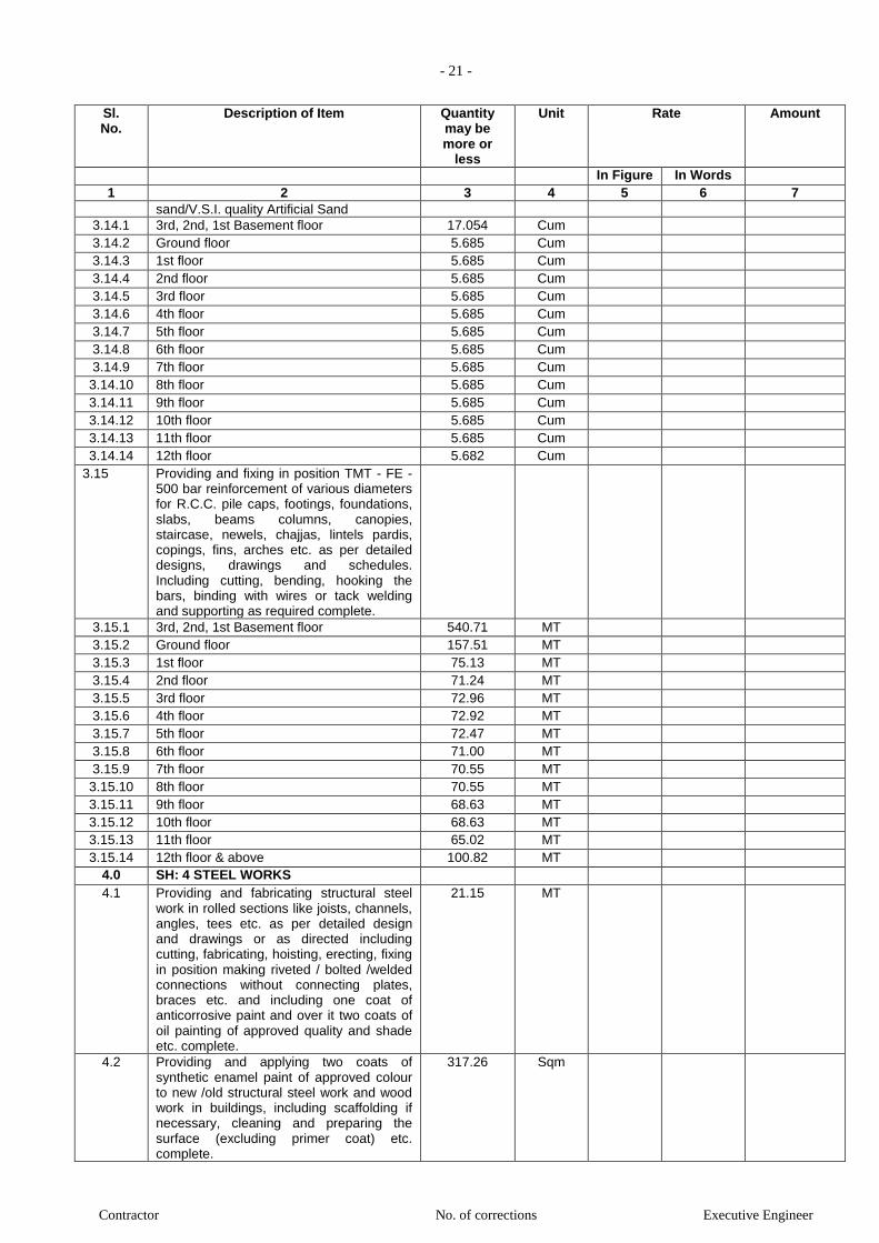
- 21 -
Contractor No. of corrections Executive Engineer
Sl. No.
Description of Item Quantity may be more or
less
Unit Rate Amount
In Figure In Words 1 2 3 4 5 6 7
sand/V.S.I. quality Artificial Sand
3.14.1 3rd, 2nd, 1st Basement floor 17.054 Cum
3.14.2 Ground floor 5.685 Cum
3.14.3 1st floor 5.685 Cum
3.14.4 2nd floor 5.685 Cum
3.14.5 3rd floor 5.685 Cum
3.14.6 4th floor 5.685 Cum
3.14.7 5th floor 5.685 Cum
3.14.8 6th floor 5.685 Cum
3.14.9 7th floor 5.685 Cum
3.14.10 8th floor 5.685 Cum
3.14.11 9th floor 5.685 Cum
3.14.12 10th floor 5.685 Cum
3.14.13 11th floor 5.685 Cum
3.14.14 12th floor 5.682 Cum
3.15 Providing and fixing in position TMT - FE - 500 bar reinforcement of various diameters for R.C.C. pile caps, footings, foundations, slabs, beams columns, canopies, staircase, newels, chajjas, lintels pardis, copings, fins, arches etc. as per detailed designs, drawings and schedules. Including cutting, bending, hooking the bars, binding with wires or tack welding and supporting as required complete.
3.15.1 3rd, 2nd, 1st Basement floor 540.71 MT
3.15.2 Ground floor 157.51 MT
3.15.3 1st floor 75.13 MT
3.15.4 2nd floor 71.24 MT
3.15.5 3rd floor 72.96 MT
3.15.6 4th floor 72.92 MT
3.15.7 5th floor 72.47 MT
3.15.8 6th floor 71.00 MT
3.15.9 7th floor 70.55 MT
3.15.10 8th floor 70.55 MT
3.15.11 9th floor 68.63 MT
3.15.12 10th floor 68.63 MT 3.15.13 11th floor 65.02 MT
3.15.14 12th floor & above 100.82 MT 4.0 SH: 4 STEEL WORKS
4.1 Providing and fabricating structural steel work in rolled sections like joists, channels, angles, tees etc. as per detailed design and drawings or as directed including cutting, fabricating, hoisting, erecting, fixing in position making riveted / bolted /welded connections without connecting plates, braces etc. and including one coat of anticorrosive paint and over it two coats of oil painting of approved quality and shade etc. complete.
21.15 MT
4.2 Providing and applying two coats of synthetic enamel paint of approved colour to new /old structural steel work and wood work in buildings, including scaffolding if necessary, cleaning and preparing the surface (excluding primer coat) etc. complete.
317.26 Sqm

- 22 -
Contractor No. of corrections Executive Engineer
Sl. No.
Description of Item Quantity may be more or
less
Unit Rate Amount
In Figure In Words 1 2 3 4 5 6 7
5.0 SH: 5 POST TENSIONING WORKS
5.1 Designing, Providing and installing Post tensioning tendon & anchorage system as per IS 1343-1980 for slabs and Beams using Galvanized steel strip ducting
146.36 MT
including (a) preparation of post- tensioning shop drawings and getting the same approved by the structural consultant and proof consultant as decided by Engineer-in charge (b) supplying, fabricating and fixing of steel bar chairs and ant bursting and anti spalling reinforcement (c) stressing of tendons with jacks equipped with hydraulic seating system for permanent wedges (d) grouting the same using cementetious Grout with necessary admixture having 28 day compressive strength of 32 N/mm2 with maximum water cement ratio as 0.45 (e) patching/concreting of anchorage system left out after stressing ends all complete as per the design requirements supplied and as per direction of Engineer-in Charge.
(For the purpose of payment length of strands shall be measured only from outer face of concrete member at one end to outer face of concrete member at another end. Extra length of strands provided on both the ends shall not be measured and paid. Steel bar chairs, anti-bursting and anti spalling reinforcement and other reinforcement bars shall be measured and paid under relevant item of reinforcement bars. Concrete for patching of anchorage system left out after stressing shall be paid under relevant item of concrete. )
Using 12.7mm dia 7-ply class II Uncoated Stress relieved strands conforming to IS: 14268-1995 and approved post tensioning anchorage system.
6.0 SH: 6 WATERPROOFING WORKS
Basement Membrane Waterproofing Providing and applying waterproofing
treatment with Fully Bonded HDPE Membrane Waterproofing on PCC below raft slab & SBS membrane on retaining wall (approved system : as per manufacturer's specification)
Important Note - Membrane should be supplied with original
manufacturer's Material Test Certificate (MTC) & membrane should be installed in strict accordance with original manufacturer's instructions (private label supplier are not allowed) and contractor should produce method statement from original product manufacturer.
6.1 Waterproofing for Raft & Retaining Wall
Specifications - Supplying & Installing waterproofing treatment by using 1.2 mm thick Nuraprufe 415 manufactured by M/s.

- 23 -
Contractor No. of corrections Executive Engineer
Sl. No.
Description of Item Quantity may be more or
less
Unit Rate Amount
In Figure In Words 1 2 3 4 5 6 7
Hitchins before casting of the base RCC slab. The pre-applied membrane gets bonded to the underneath of the poured concrete used as base slab. The membrane shall consist of a thick HDPE
film, a highly aggressive pressure sensitive adhesive and weather resisting coating which bonds integrally to poured concrete of base slab. The membrane shall conforms to basement waterproofing protection to grades 2, 3 & 4 as defined in BS 8102:2009. The waterproofing membrane shall have following minimum properties :
a) Resist hydrostatic pressure of up to 70 m head of water as per ASTM D5385;
b) Puncture Resistance of 990 N (as per ASTM E154)
c) Elongation of 300 % (as per ASTM D412)
d)Tensile strength of 27.6 Mpa (as per ASTM D412)
The membrane shall be installed with standard 75 mm selvedge laps and 75mm end laps taped with Nuraprufe Tape, a double side coated adhesive tape over the entire area and turned up on to a vertical timber formwork, as per recommendations / drawings. The membrane shall be laid over the concrete blinding having smooth dried surface including necessary removal of release liner while applying, necessary overlaps between the membranes and fixing overlaps by Nuraprufe tape, firm rolling onto the surface to get a tight seal, etc. complete all as per manufacturer’s recommendations, etc. complete with all lead and lift for all materials and labour and as directed, at all heights and all locations viz. below the slab. The scope of work shall include treatment of Pressure Release Pipes in accordance to the method statement as per manufacturer specifications viz. wrapping the Pressure release pipe with waterproofing membrane sheet up to 300 mm height and treating the same with Liquid Membrane around the periphery of the pipe.
6.1.1 Below raft slab 2563.1 Sqm
6.1.2 For retaining wall 1973.6 Sqm Sealing of Dowel Anchor penetration : -The
32mm dia. Dowel anchor penetration will be sealed all around on the membrane with 2 component liquid membrane. All system to be installed as per manufacturer's recommendations, etc. complete with all lead and lift for all materials and labour and as directed by Engineer in-charge.
1140 No.
6.1.1 Below raft slab 2563.1 Sqm
6.1.2 For retaining wall 1973.6 Sqm Sealing of Dowel Anchor penetration : -The
32mm dia. Dowel anchor penetration will 1140 No.
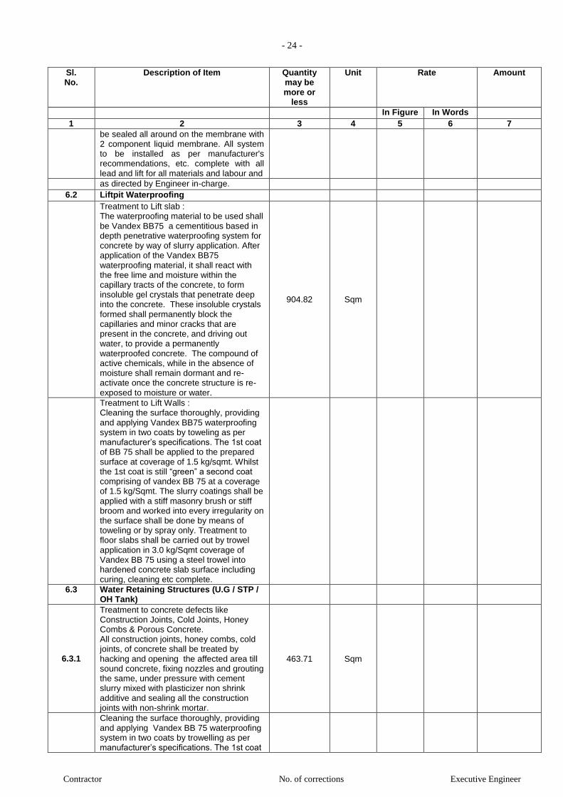
- 24 -
Contractor No. of corrections Executive Engineer
Sl. No.
Description of Item Quantity may be more or
less
Unit Rate Amount
In Figure In Words 1 2 3 4 5 6 7
be sealed all around on the membrane with 2 component liquid membrane. All system to be installed as per manufacturer's recommendations, etc. complete with all lead and lift for all materials and labour and
as directed by Engineer in-charge. 6.2 Liftpit Waterproofing
Treatment to Lift slab : The waterproofing material to be used shall be Vandex BB75 a cementitious based in depth penetrative waterproofing system for concrete by way of slurry application. After application of the Vandex BB75 waterproofing material, it shall react with the free lime and moisture within the capillary tracts of the concrete, to form insoluble gel crystals that penetrate deep into the concrete. These insoluble crystals formed shall permanently block the capillaries and minor cracks that are present in the concrete, and driving out water, to provide a permanently waterproofed concrete. The compound of active chemicals, while in the absence of moisture shall remain dormant and re-activate once the concrete structure is re-exposed to moisture or water.
904.82
Sqm
Treatment to Lift Walls : Cleaning the surface thoroughly, providing and applying Vandex BB75 waterproofing system in two coats by toweling as per manufacturer’s specifications. The 1st coat of BB 75 shall be applied to the prepared surface at coverage of 1.5 kg/sqmt. Whilst the 1st coat is still “green” a second coat comprising of vandex BB 75 at a coverage of 1.5 kg/Sqmt. The slurry coatings shall be applied with a stiff masonry brush or stiff broom and worked into every irregularity on the surface shall be done by means of toweling or by spray only. Treatment to floor slabs shall be carried out by trowel application in 3.0 kg/Sqmt coverage of Vandex BB 75 using a steel trowel into hardened concrete slab surface including curing, cleaning etc complete.
6.3 Water Retaining Structures (U.G / STP / OH Tank)
6.3.1
Treatment to concrete defects like Construction Joints, Cold Joints, Honey Combs & Porous Concrete. All construction joints, honey combs, cold joints, of concrete shall be treated by hacking and opening the affected area till sound concrete, fixing nozzles and grouting the same, under pressure with cement slurry mixed with plasticizer non shrink additive and sealing all the construction joints with non-shrink mortar.
463.71 Sqm
Cleaning the surface thoroughly, providing and applying Vandex BB 75 waterproofing system in two coats by trowelling as per manufacturer’s specifications. The 1st coat
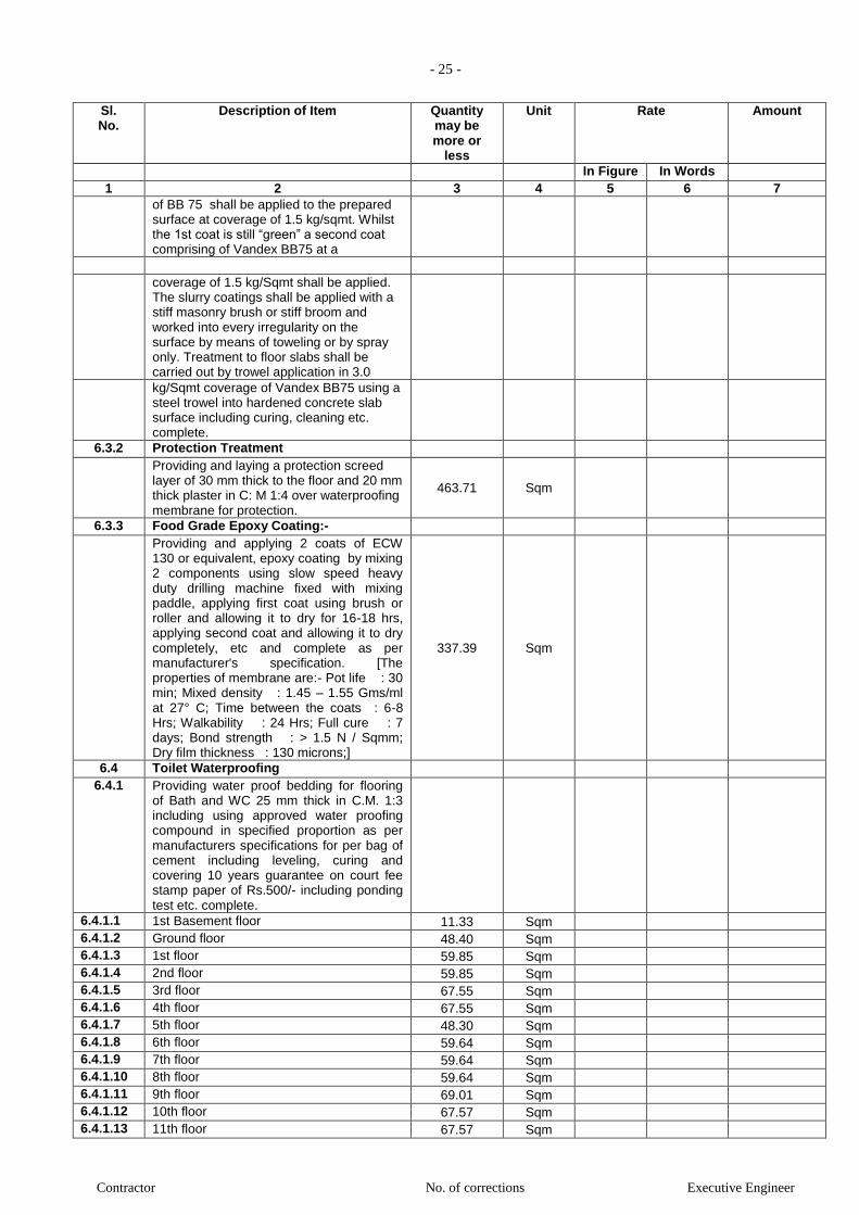
- 25 -
Contractor No. of corrections Executive Engineer
Sl. No.
Description of Item Quantity may be more or
less
Unit Rate Amount
In Figure In Words 1 2 3 4 5 6 7
of BB 75 shall be applied to the prepared surface at coverage of 1.5 kg/sqmt. Whilst the 1st coat is still “green” a second coat comprising of Vandex BB75 at a
coverage of 1.5 kg/Sqmt shall be applied. The slurry coatings shall be applied with a stiff masonry brush or stiff broom and worked into every irregularity on the surface by means of toweling or by spray only. Treatment to floor slabs shall be carried out by trowel application in 3.0
kg/Sqmt coverage of Vandex BB75 using a steel trowel into hardened concrete slab surface including curing, cleaning etc. complete.
6.3.2 Protection Treatment Providing and laying a protection screed
layer of 30 mm thick to the floor and 20 mm thick plaster in C: M 1:4 over waterproofing membrane for protection.
463.71 Sqm
6.3.3 Food Grade Epoxy Coating:- Providing and applying 2 coats of ECW
130 or equivalent, epoxy coating by mixing 2 components using slow speed heavy duty drilling machine fixed with mixing paddle, applying first coat using brush or roller and allowing it to dry for 16-18 hrs, applying second coat and allowing it to dry completely, etc and complete as per manufacturer's specification. [The properties of membrane are:- Pot life : 30 min; Mixed density : 1.45 – 1.55 Gms/ml at 27° C; Time between the coats : 6-8 Hrs; Walkability : 24 Hrs; Full cure : 7 days; Bond strength : > 1.5 N / Sqmm; Dry film thickness : 130 microns;]
337.39 Sqm
6.4 Toilet Waterproofing 6.4.1 Providing water proof bedding for flooring
of Bath and WC 25 mm thick in C.M. 1:3 including using approved water proofing compound in specified proportion as per manufacturers specifications for per bag of cement including leveling, curing and covering 10 years guarantee on court fee stamp paper of Rs.500/- including ponding test etc. complete.
6.4.1.1 1st Basement floor 11.33 Sqm 6.4.1.2 Ground floor 48.40 Sqm 6.4.1.3 1st floor 59.85 Sqm 6.4.1.4 2nd floor 59.85 Sqm 6.4.1.5 3rd floor 67.55 Sqm 6.4.1.6 4th floor 67.55 Sqm 6.4.1.7 5th floor 48.30 Sqm 6.4.1.8 6th floor 59.64 Sqm 6.4.1.9 7th floor 59.64 Sqm 6.4.1.10 8th floor 59.64 Sqm 6.4.1.11 9th floor 69.01 Sqm 6.4.1.12 10th floor 67.57 Sqm 6.4.1.13 11th floor 67.57 Sqm
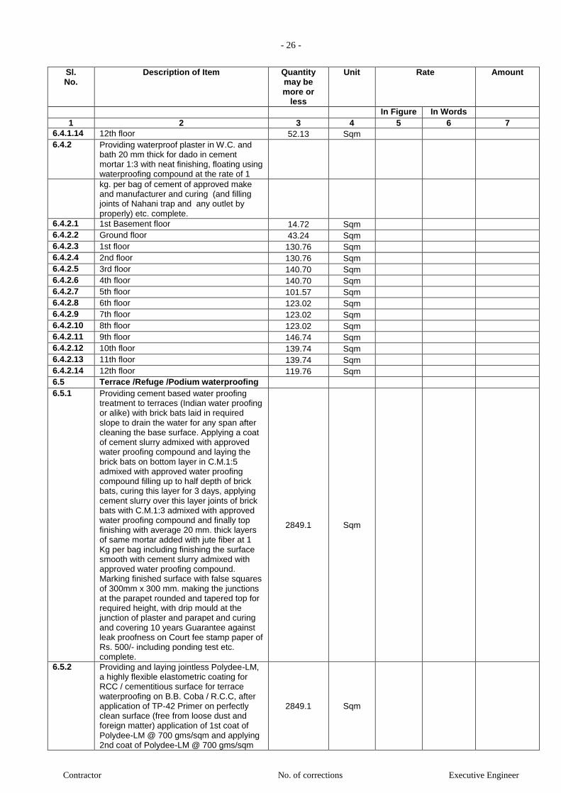
- 26 -
Contractor No. of corrections Executive Engineer
Sl. No.
Description of Item Quantity may be more or
less
Unit Rate Amount
In Figure In Words 1 2 3 4 5 6 7
6.4.1.14 12th floor 52.13 Sqm 6.4.2 Providing waterproof plaster in W.C. and
bath 20 mm thick for dado in cement mortar 1:3 with neat finishing, floating using waterproofing compound at the rate of 1
kg. per bag of cement of approved make and manufacturer and curing (and filling joints of Nahani trap and any outlet by properly) etc. complete.
6.4.2.1 1st Basement floor 14.72 Sqm 6.4.2.2 Ground floor 43.24 Sqm 6.4.2.3 1st floor 130.76 Sqm 6.4.2.4 2nd floor 130.76 Sqm 6.4.2.5 3rd floor 140.70 Sqm 6.4.2.6 4th floor 140.70 Sqm 6.4.2.7 5th floor 101.57 Sqm 6.4.2.8 6th floor 123.02 Sqm 6.4.2.9 7th floor 123.02 Sqm 6.4.2.10 8th floor 123.02 Sqm 6.4.2.11 9th floor 146.74 Sqm 6.4.2.12 10th floor 139.74 Sqm 6.4.2.13 11th floor 139.74 Sqm 6.4.2.14 12th floor 119.76 Sqm 6.5 Terrace /Refuge /Podium waterproofing 6.5.1 Providing cement based water proofing
treatment to terraces (Indian water proofing or alike) with brick bats laid in required slope to drain the water for any span after cleaning the base surface. Applying a coat of cement slurry admixed with approved water proofing compound and laying the brick bats on bottom layer in C.M.1:5 admixed with approved water proofing compound filling up to half depth of brick bats, curing this layer for 3 days, applying cement slurry over this layer joints of brick bats with C.M.1:3 admixed with approved water proofing compound and finally top finishing with average 20 mm. thick layers of same mortar added with jute fiber at 1 Kg per bag including finishing the surface smooth with cement slurry admixed with approved water proofing compound. Marking finished surface with false squares of 300mm x 300 mm. making the junctions at the parapet rounded and tapered top for required height, with drip mould at the junction of plaster and parapet and curing and covering 10 years Guarantee against leak proofness on Court fee stamp paper of Rs. 500/- including ponding test etc. complete.
2849.1 Sqm
6.5.2 Providing and laying jointless Polydee-LM, a highly flexible elastometric coating for RCC / cementitious surface for terrace waterproofing on B.B. Coba / R.C.C, after application of TP-42 Primer on perfectly clean surface (free from loose dust and foreign matter) application of 1st coat of Polydee-LM @ 700 gms/sqm and applying 2nd coat of Polydee-LM @ 700 gms/sqm
2849.1 Sqm
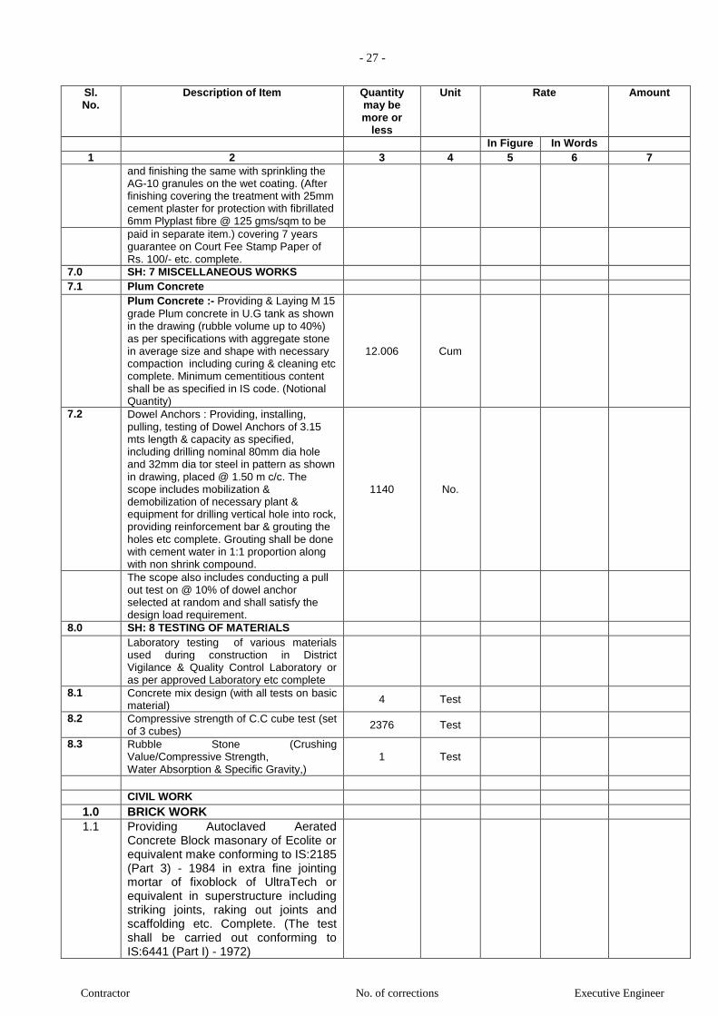
- 27 -
Contractor No. of corrections Executive Engineer
Sl. No.
Description of Item Quantity may be more or
less
Unit Rate Amount
In Figure In Words 1 2 3 4 5 6 7
and finishing the same with sprinkling the AG-10 granules on the wet coating. (After finishing covering the treatment with 25mm cement plaster for protection with fibrillated 6mm Plyplast fibre @ 125 gms/sqm to be
paid in separate item.) covering 7 years guarantee on Court Fee Stamp Paper of Rs. 100/- etc. complete.
7.0 SH: 7 MISCELLANEOUS WORKS 7.1 Plum Concrete Plum Concrete :- Providing & Laying M 15
grade Plum concrete in U.G tank as shown in the drawing (rubble volume up to 40%) as per specifications with aggregate stone in average size and shape with necessary compaction including curing & cleaning etc complete. Minimum cementitious content shall be as specified in IS code. (Notional Quantity)
12.006 Cum
7.2 Dowel Anchors : Providing, installing, pulling, testing of Dowel Anchors of 3.15 mts length & capacity as specified, including drilling nominal 80mm dia hole and 32mm dia tor steel in pattern as shown in drawing, placed @ 1.50 m c/c. The scope includes mobilization & demobilization of necessary plant & equipment for drilling vertical hole into rock, providing reinforcement bar & grouting the holes etc complete. Grouting shall be done with cement water in 1:1 proportion along with non shrink compound.
1140 No.
The scope also includes conducting a pull out test on @ 10% of dowel anchor selected at random and shall satisfy the design load requirement.
8.0 SH: 8 TESTING OF MATERIALS Laboratory testing of various materials
used during construction in District Vigilance & Quality Control Laboratory or as per approved Laboratory etc complete
8.1 Concrete mix design (with all tests on basic material)
4 Test
8.2 Compressive strength of C.C cube test (set of 3 cubes)
2376 Test
8.3 Rubble Stone (Crushing Value/Compressive Strength, Water Absorption & Specific Gravity,)
1 Test
CIVIL WORK
1.0 BRICK WORK
1.1 Providing Autoclaved Aerated Concrete Block masonary of Ecolite or equivalent make conforming to IS:2185 (Part 3) - 1984 in extra fine jointing mortar of fixoblock of UltraTech or equivalent in superstructure including striking joints, raking out joints and scaffolding etc. Complete. (The test shall be carried out conforming to IS:6441 (Part I) - 1972)
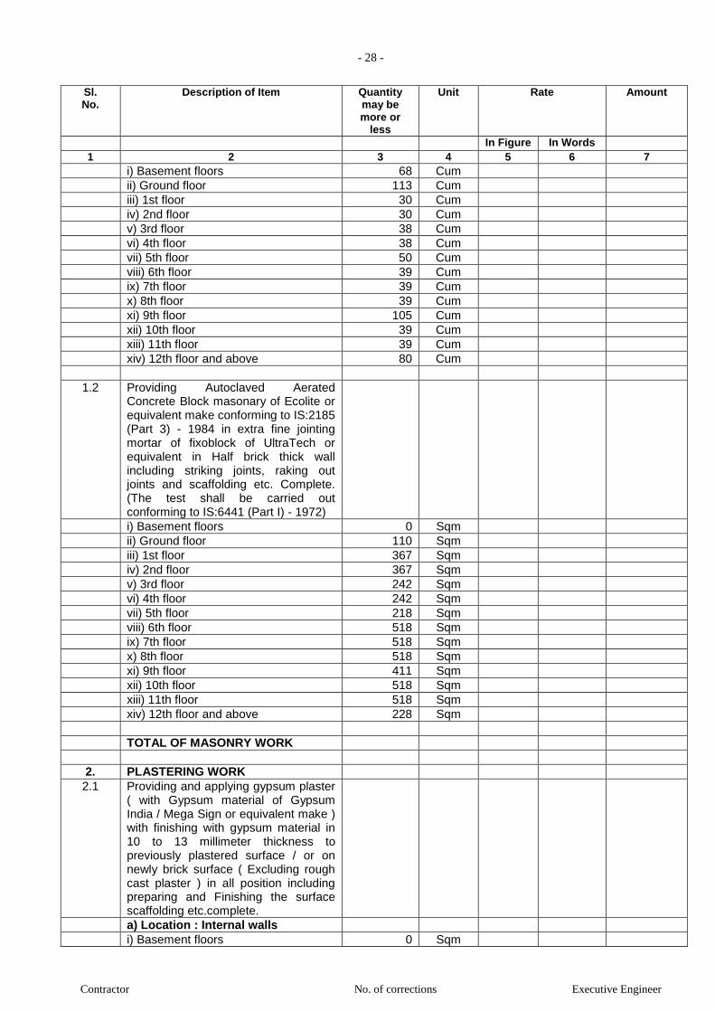
- 28 -
Contractor No. of corrections Executive Engineer
Sl. No.
Description of Item Quantity may be more or
less
Unit Rate Amount
In Figure In Words 1 2 3 4 5 6 7
i) Basement floors 68 Cum
ii) Ground floor 113 Cum
iii) 1st floor 30 Cum
iv) 2nd floor 30 Cum
v) 3rd floor 38 Cum
vi) 4th floor 38 Cum
vii) 5th floor 50 Cum
viii) 6th floor 39 Cum
ix) 7th floor 39 Cum
x) 8th floor 39 Cum
xi) 9th floor 105 Cum
xii) 10th floor 39 Cum
xiii) 11th floor 39 Cum
xiv) 12th floor and above 80 Cum
1.2 Providing Autoclaved Aerated Concrete Block masonary of Ecolite or equivalent make conforming to IS:2185 (Part 3) - 1984 in extra fine jointing mortar of fixoblock of UltraTech or equivalent in Half brick thick wall including striking joints, raking out joints and scaffolding etc. Complete. (The test shall be carried out conforming to IS:6441 (Part I) - 1972)
i) Basement floors 0 Sqm
ii) Ground floor 110 Sqm
iii) 1st floor 367 Sqm
iv) 2nd floor 367 Sqm
v) 3rd floor 242 Sqm
vi) 4th floor 242 Sqm
vii) 5th floor 218 Sqm
viii) 6th floor 518 Sqm
ix) 7th floor 518 Sqm
x) 8th floor 518 Sqm
xi) 9th floor 411 Sqm
xii) 10th floor 518 Sqm
xiii) 11th floor 518 Sqm
xiv) 12th floor and above 228 Sqm
TOTAL OF MASONRY WORK
2. PLASTERING WORK
2.1 Providing and applying gypsum plaster ( with Gypsum material of Gypsum India / Mega Sign or equivalent make ) with finishing with gypsum material in 10 to 13 millimeter thickness to previously plastered surface / or on newly brick surface ( Excluding rough cast plaster ) in all position including preparing and Finishing the surface scaffolding etc.complete.
a) Location : Internal walls
i) Basement floors 0 Sqm

- 29 -
Contractor No. of corrections Executive Engineer
Sl. No.
Description of Item Quantity may be more or
less
Unit Rate Amount
In Figure In Words 1 2 3 4 5 6 7
ii) Ground floor 1,684 Sqm
iii) 1st floor 1,048 Sqm
iv) 2nd floor 1,048 Sqm
v) 3rd floor 1,450 Sqm
vi) 4th floor 1,450 Sqm
vii) 5th floor 1,402 Sqm
viii) 6th floor 1,450 Sqm
ix) 7th floor 1,450 Sqm
x) 8th floor 1,450 Sqm
xi) 9th floor 1,672 Sqm
xii) 10th floor 1,450 Sqm
xiii) 11th floor 1,450 Sqm
xiv) 12th floor and above 1,812 Sqm
2.2 Providing internal cement plaster 12mm thick in single coat in cement mortar 1:5 without neeru finish to concrete or brick surfaces, in all positions including scaffolding and curing etc. complete.
i) Basement floors 4,573 Sqm
ii) Ground floor 0 Sqm
iii) 1st floor 0 Sqm
iv) 2nd floor 0 Sqm
v) 3rd floor 0 Sqm
vi) 4th floor 0 Sqm
vii) 5th floor 0 Sqm
viii) 6th floor 0 Sqm
ix) 7th floor 0 Sqm
x) 8th floor 0 Sqm
xi) 9th floor 0 Sqm
xii) 10th floor 0 Sqm
xiii) 11th floor 0 Sqm
xiv) 12th floor and above 0 Sqm
a) Location : Internal ceilings
i) Basement floors 0 Sqm
ii) Ground floor 0 Sqm
iii) 1st floor 0 Sqm
iv) 2nd floor 0 Sqm
v) 3rd floor 0 Sqm
vii) 5th floor 0 Sqm
viii) 6th floor 0 Sqm
ix) 7th floor 0 Sqm
x) 8th floor 0 Sqm
xi) 9th floor 0 Sqm xii) 10th floor 0 Sqm
xiii) 11th floor 0 Sqm
xiv) 12th floor and above 0 Sqm
2.3 Providing sand faced plaster externally in cement mortar using approved screened sand, in all positions including base coat of 15 mm thick in cement mortar 1:4 using waterproofing compound at 1 kg per cement bag
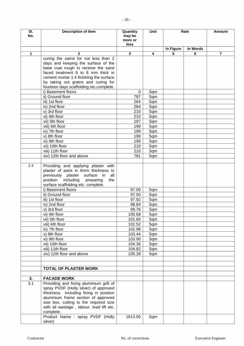
- 30 -
Contractor No. of corrections Executive Engineer
Sl. No.
Description of Item Quantity may be more or
less
Unit Rate Amount
In Figure In Words 1 2 3 4 5 6 7
curing the same for not less than 2 days and keeping the surface of the base coat rough to receive the sand faced treatment 6 to 8 mm thick in cement mortar 1:4 finishing the surface by taking out grains and curing for fourteen days scaffolding etc.complete.
i) Basement floors 0 Sqm
ii) Ground floor 787 Sqm
iii) 1st floor 264 Sqm
iv) 2nd floor 264 Sqm
v) 3rd floor 210 Sqm
vi) 4th floor 210 Sqm
vii) 5th floor 197 Sqm
viii) 6th floor 199 Sqm
ix) 7th floor 199 Sqm
x) 8th floor 199 Sqm
xi) 9th floor 199 Sqm
xii) 10th floor 210 Sqm
xiii) 11th floor 210 Sqm
xiv) 12th floor and above 781 Sqm
2.4 Providing and applying plaster with plaster of paris in 6mm thickness to previously plaster surface in all position including preparing the surface scaffolding etc. complete.
i) Basement floors 97.00 Sqm
ii) Ground floor 97.00 Sqm
iii) 1st floor 97.92 Sqm
iv) 2nd floor 98.84 Sqm
v) 3rd floor 99.76 Sqm
vi) 4th floor 100.68 Sqm
vii) 5th floor 101.60 Sqm
viii) 6th floor 102.52 Sqm
ix) 7th floor 102.98 Sqm
x) 8th floor 103.44 Sqm
xi) 9th floor 103.90 Sqm
xii) 10th floor 104.36 Sqm
xiii) 11th floor 104.82 Sqm
xiv) 12th floor and above 105.28 Sqm
TOTAL OF PLASTER WORK
3. FACADE WORK
3.1 Providing and fixing aluminium grill of spray PVDF (Holly silver) of approved thickness including fixing in position aluminium frame section of approved size box, cutting to the required size with all wastage , labour, lead lift etc. complete.
Product Name : spray PVDF (Holly silver)
1613.00
Sqm
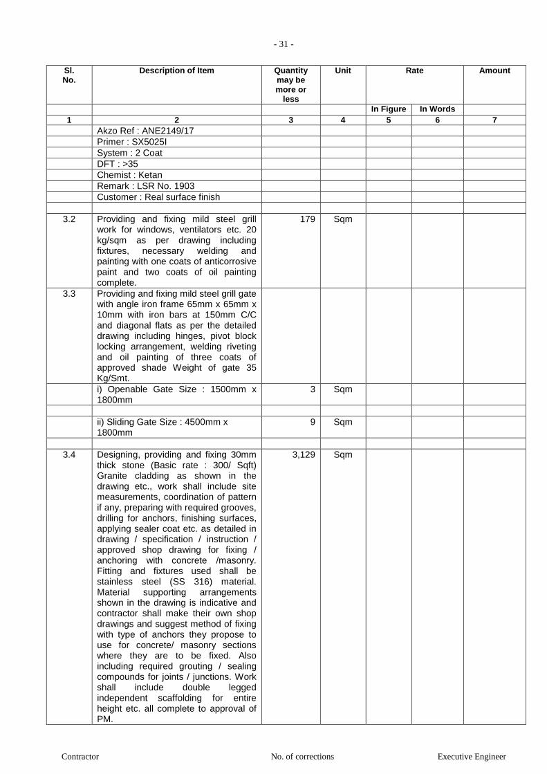
- 31 -
Contractor No. of corrections Executive Engineer
Sl. No.
Description of Item Quantity may be more or
less
Unit Rate Amount
In Figure In Words 1 2 3 4 5 6 7
Akzo Ref : ANE2149/17
Primer : SX5025I
System : 2 Coat
DFT : >35
Chemist : Ketan
Remark : LSR No. 1903
Customer : Real surface finish
3.2 Providing and fixing mild steel grill work for windows, ventilators etc. 20 kg/sqm as per drawing including fixtures, necessary welding and painting with one coats of anticorrosive paint and two coats of oil painting complete.
179 Sqm
3.3 Providing and fixing mild steel grill gate with angle iron frame 65mm x 65mm x 10mm with iron bars at 150mm C/C and diagonal flats as per the detailed drawing including hinges, pivot block locking arrangement, welding riveting and oil painting of three coats of approved shade Weight of gate 35 Kg/Smt.
i) Openable Gate Size : 1500mm x 1800mm
3 Sqm
ii) Sliding Gate Size : 4500mm x 1800mm
9 Sqm
3.4 Designing, providing and fixing 30mm thick stone (Basic rate : 300/ Sqft) Granite cladding as shown in the drawing etc., work shall include site measurements, coordination of pattern if any, preparing with required grooves, drilling for anchors, finishing surfaces, applying sealer coat etc. as detailed in drawing / specification / instruction / approved shop drawing for fixing / anchoring with concrete /masonry. Fitting and fixtures used shall be stainless steel (SS 316) material. Material supporting arrangements shown in the drawing is indicative and contractor shall make their own shop drawings and suggest method of fixing with type of anchors they propose to use for concrete/ masonry sections where they are to be fixed. Also including required grouting / sealing compounds for joints / junctions. Work shall include double legged independent scaffolding for entire height etc. all complete to approval of PM.
3,129 Sqm
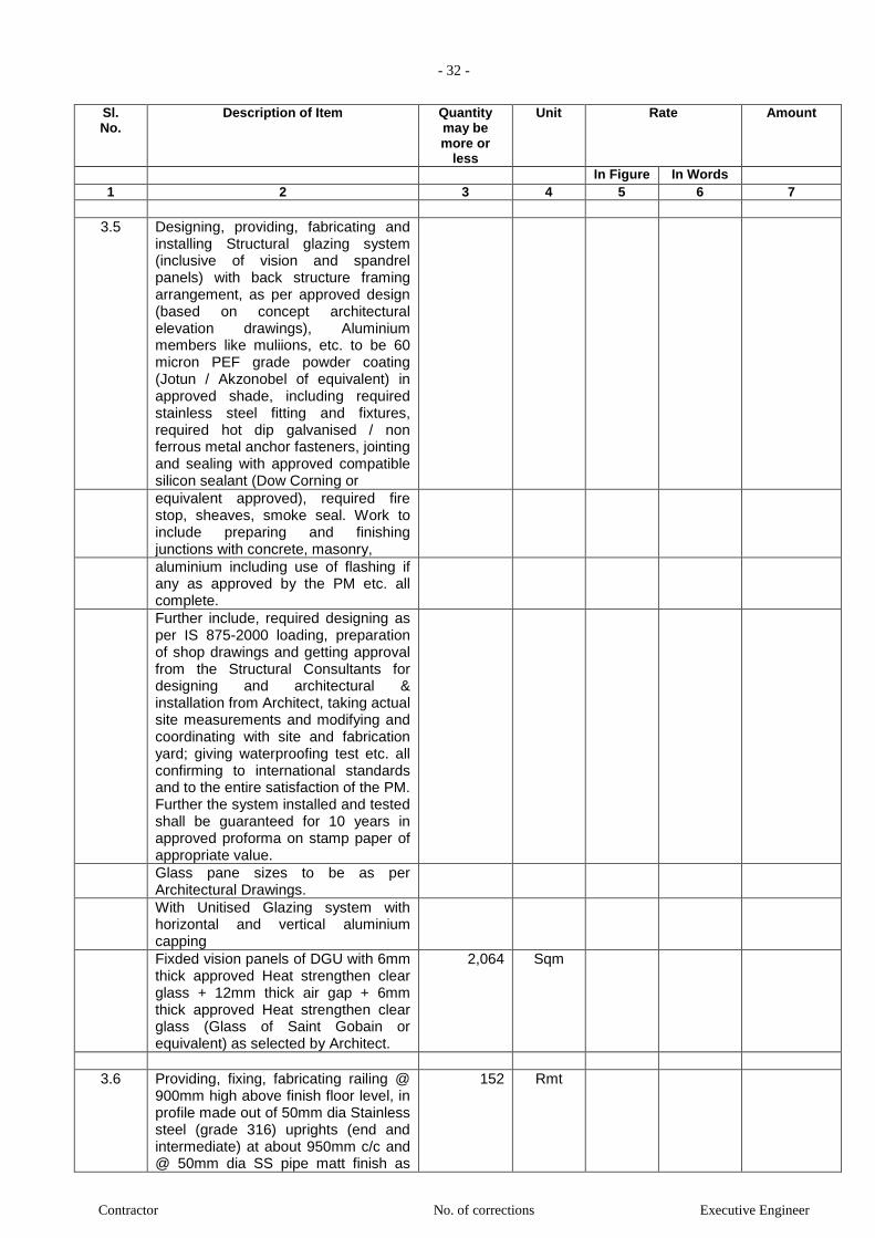
- 32 -
Contractor No. of corrections Executive Engineer
Sl. No.
Description of Item Quantity may be more or
less
Unit Rate Amount
In Figure In Words 1 2 3 4 5 6 7
3.5 Designing, providing, fabricating and installing Structural glazing system (inclusive of vision and spandrel panels) with back structure framing arrangement, as per approved design (based on concept architectural elevation drawings), Aluminium members like muliions, etc. to be 60 micron PEF grade powder coating (Jotun / Akzonobel of equivalent) in approved shade, including required stainless steel fitting and fixtures, required hot dip galvanised / non ferrous metal anchor fasteners, jointing and sealing with approved compatible silicon sealant (Dow Corning or
equivalent approved), required fire stop, sheaves, smoke seal. Work to include preparing and finishing junctions with concrete, masonry,
aluminium including use of flashing if any as approved by the PM etc. all complete.
Further include, required designing as per IS 875-2000 loading, preparation of shop drawings and getting approval from the Structural Consultants for designing and architectural & installation from Architect, taking actual site measurements and modifying and coordinating with site and fabrication yard; giving waterproofing test etc. all confirming to international standards and to the entire satisfaction of the PM. Further the system installed and tested shall be guaranteed for 10 years in approved proforma on stamp paper of appropriate value.
Glass pane sizes to be as per Architectural Drawings.
With Unitised Glazing system with horizontal and vertical aluminium capping
Fixded vision panels of DGU with 6mm thick approved Heat strengthen clear glass + 12mm thick air gap + 6mm thick approved Heat strengthen clear glass (Glass of Saint Gobain or equivalent) as selected by Architect.
2,064 Sqm
3.6 Providing, fixing, fabricating railing @ 900mm high above finish floor level, in profile made out of 50mm dia Stainless steel (grade 316) uprights (end and intermediate) at about 950mm c/c and @ 50mm dia SS pipe matt finish as
152 Rmt

- 33 -
Contractor No. of corrections Executive Engineer
Sl. No.
Description of Item Quantity may be more or
less
Unit Rate Amount
In Figure In Words 1 2 3 4 5 6 7
hand rail including 10mm thick clear toughened glass for railing, SS. rosette cover fixed with SS pins, dowels, clamps, rubber, screws, gaskets etc. including required jointing and sealing with approved quality silicon sealant etc. all complete as per detail drawing, specification to entire satisfaction of PM. Work includes preparing shop drawings to scale with joinery and fixing details and further includes providing samples and preparing full scale mockup samples for approval.
3.7 Designing, providing, fabricating and fixing in position Glass canopy with 13.52mm thick laminated glass (6mm thick inner clear toughened glass + 1.52mm thick PVB of approved colour and make + 6mm thick outer clear toughened glass of Saint Gobain or
equivalent approved, supported on MS structural steel framing (as per design of Structural Consultant and paid separately), as detailed in structural and architectural concept drawings and approved in shop drawing; including required fixtures and fittings of stainless steel (SS 304), anchor fasteners / hooks, required flashings / trims, jointing and sealing with approved silicon sealant, and finishing junctions with steel, concrete, stone, timber, aluminium, glass, etc. all complete. to the entire satisfaction of PM. Further include required preparation of shop drawings and getting approval from the Architect and structural consultants, providing samples, mockups, taking actual site measurements and modifying and coordinating with site and fabrication yard, all conforming to international standards etc. complete to the approval of PM.
3.8 Providing and fixing 300mm high x
6mm thick SS (314) strips. SS strips to be inserted properly in the surface behind and to be in brush finish as per detail drawing. Surface to be flushed with adjoining surface.
3,413 Rmt
TOTAL OF FACADE WORK
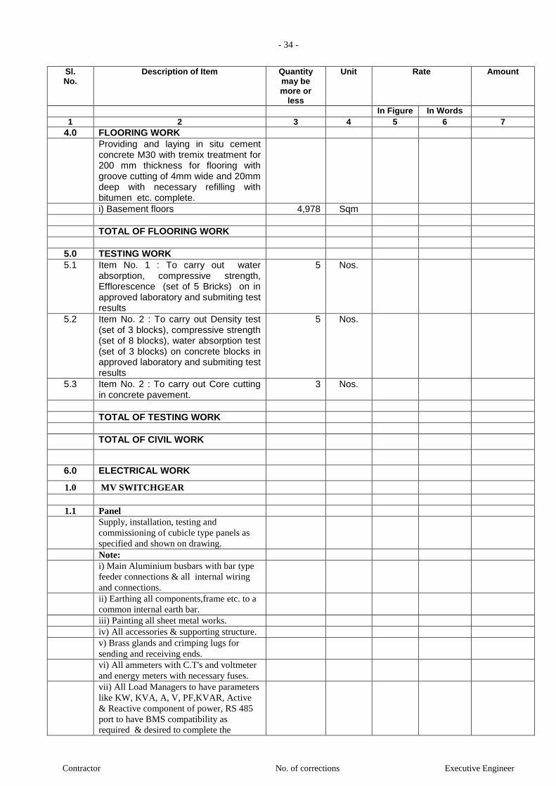
- 34 -
Contractor No. of corrections Executive Engineer
Sl. No.
Description of Item Quantity may be more or
less
Unit Rate Amount
In Figure In Words 1 2 3 4 5 6 7
4.0 FLOORING WORK
Providing and laying in situ cement concrete M30 with tremix treatment for 200 mm thickness for flooring with groove cutting of 4mm wide and 20mm deep with necessary refilling with bitumen etc. complete.
i) Basement floors 4,978 Sqm
TOTAL OF FLOORING WORK
5.0 TESTING WORK
5.1 Item No. 1 : To carry out water absorption, compressive strength, Efflorescence (set of 5 Bricks) on in approved laboratory and submiting test results
5 Nos.
5.2 Item No. 2 : To carry out Density test (set of 3 blocks), compressive strength (set of 8 blocks), water absorption test (set of 3 blocks) on concrete blocks in approved laboratory and submiting test results
5 Nos.
5.3 Item No. 2 : To carry out Core cutting in concrete pavement.
3 Nos.
TOTAL OF TESTING WORK
TOTAL OF CIVIL WORK
6.0 ELECTRICAL WORK
1.0 MV SWITCHGEAR
1.1 Panel
Supply, installation, testing and
commissioning of cubicle type panels as
specified and shown on drawing.
Note:
i) Main Aluminium busbars with bar type
feeder connections & all internal wiring
and connections.
ii) Earthing all components,frame etc. to a
common internal earth bar.
iii) Painting all sheet metal works.
iv) All accessories & supporting structure.
v) Brass glands and crimping lugs for
sending and receiving ends.
vi) All ammeters with C.T's and voltmeter
and energy meters with necessary fuses.
vii) All Load Managers to have parameters
like KW, KVA, A, V, PF,KVAR, Active
& Reactive component of power, RS 485
port to have BMS compatibility as
required & desired to complete the

- 35 -
Contractor No. of corrections Executive Engineer
Sl. No.
Description of Item Quantity may be more or
less
Unit Rate Amount
In Figure In Words 1 2 3 4 5 6 7
system. vii) Panel components as specified.
viii) MS base frame.
ix) All switch gear to have short circuit
levels as specified.
a Main Distribution Panel + APFCR
Panel
1 Nos.
b Fire Fighting Panel
1 Nos.
c Basement Ventilation Panel
1 Nos.
1.2 DB ( Distribution Boards)
General Specifications
Supply, installation, testing &
commissioning of 500V Distribution
Boards as specified & shown on drawing
with necessary blankplates(if require),
interconnection and accessories
Note:
i) Copper busbars together with tapped
neutral bar for individual phases.
ii) Copper earth strip with tapping for EEC
iii) Busbar mounting mcb's individually
lockable in off position.
iv) Interconnections and earthing.
v) Sheet steel enclosure suitable for
recessed or surface mounting with hinged
lockable doors interlocked with the
incomer switch.
vi) Phase to phase barriers in case of 3Ph
boards.
vii) Necessary support frame & painting,
labelling, phase indicating lamps with
fuses etc. complete.
viii) DOUBLE DOOR
ix) Prefarably standard DB's of specified
makes as per list of materials shall be used
CSR Base Specifications
a ETPN DB - (12 WAY) 2 Nos.
Supplying & erecting triple pole and
neutral distribution board (TPNDB) with
door surface/ flush mounted SPMCB of 12
ways/phase (36 Poles) on iron/ G.I.
frame/wooden board. (Horizontal Busbar
type)
as per specification no. SW-
SWR/MCBDB
IP Protection: IP 20 / IP 43 / IP 54
Incommer:
b upplying, erecting & marking TPMCB 6 A
to 7 Nos.
32A in provided distribution board as per

- 36 -
Contractor No. of corrections Executive Engineer
Sl. No.
Description of Item Quantity may be more or
less
Unit Rate Amount
In Figure In Words 1 2 3 4 5 6 7
specification No. SW-SWR/MCB
c Providing, erecting & commissioning
RCCB 22 Nos.
only of electro magnetic type with
30/100/300
mA sensitivity and having capacity of 16/
25A.
2 pole complete as per specification No.
SWRCCB/RCCB
Outgoing:
d Supplying, erecting & marking SPMCB
6A to 163 Nos.
32A, C-series (for motor/power) in
provided
distribution board as per specification No.
SWSWR/MCB
e ETPN DB - (8 WAY) 5 Nos.
Supplying & erecting triple pole and
neutral
distribution board (TPNDB) with door
surface/ flush mounted SPMCB of 24
ways, on
iron/ G.I. frame/wooden board.(Horizontal
type)
as per specification No. SW-
SWR/MCBDB
IP Protection: IP 20 / IP 43 / IP 54
f VTPN DB - (8 WAY) 2 Nos.
Supplying & erecting triple pole and
neutral
distribution board (TPNDB) with door
surface/
flush mounted suitable for 3 Pole MCCB
as
Incommer & outgoing SP MCB (24 Poles)
or
TP MCB of 8 ways (24 Poles) , on iron/
G.I.
frame. (Vertical Busbar type) as per
specification No. SW-SWR/MCBDB1
IP Protection: IP 20 / IP 43 / IP 54
Incommer:
g Supplying, erecting & marking TPMCB
40A to 2 Nos.
63A in provided distribution board as per
specification No. SW-SWR/MCB
Outgoing:
TOTAL OF MV SWITCHGEAR /
POWER PANEL / DB
2.0 LT CABLING

- 37 -
Contractor No. of corrections Executive Engineer
Sl. No.
Description of Item Quantity may be more or
less
Unit Rate Amount
In Figure In Words 1 2 3 4 5 6 7
2.1 LT Cable (Power Cabling )
General Specifications
Supply and laying of 1.1kV Voltage
grade, aluminium / copper conductor,
XLPE insulated, steel armoured, power /
control cables. The cables shall be laid in
tray / hume pipe / in ready made trenches,
with nylon cable ties / MS Clamps @
600mm interval etc., as required.
CSR Base Specifications
2.1.1 7.2 LT Cables (Copper) (CB-LT/CU)
a Supplying, erecting & terminating PVC 200 Mtrs.
armoured cable 3 core 2.5 sq mm copper
conductor continuous 5.48 sq mm (12
SWG)
G.I. earth wire complete erected with
glands &
lugs, on wall/ trusses/pole or laid in
provided
trench/ pipe as per specification no. CB-
LT/CU
b Supplying, erecting & terminating PVC 150 Mtrs.
armoured cable 3 core 4 sq mm copper
conductor continuous 5.48 sq mm (12
SWG)
G.I. earth wire complete erected with
glands &
lugs, on wall/ trusses/pole or laid in
provided
trench/ pipe as per specification no. CB-
LT/CU
c Supplying, erecting & terminating PVC 175 Mtrs.
armoured cable 3 core 6 sq mm copper
conductor continuous 5.48 sq mm (12
SWG)
G.I. earth wire complete erected with
glands &
lugs, on wall/ trusses/pole or laid in
provided
trench/ pipe as per specification no. CB-
LT/CU
c Supplying, erecting & terminating PVC 200 Mtrs.
armoured cable 3 core 10 sq mm copper
conductor continuous 5.48 sq mm (12
SWG)
G.I. earth wire complete erected with
glands &
lugs, on wall/ trusses/pole or laid in
provided
trench/ pipe as per specification no. CB-
LT/CU
e upplying, erecting & terminating PVC 500 Mtrs.
armoured cable 4 core 4 sq mm copper
conductor
continuous 5.48 sq mm (12 SWG)
G.I. earth wire complete erected with
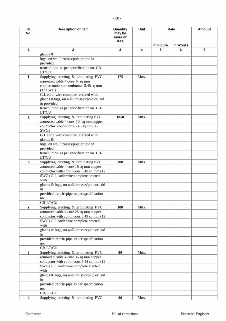
- 38 -
Contractor No. of corrections Executive Engineer
Sl. No.
Description of Item Quantity may be more or
less
Unit Rate Amount
In Figure In Words 1 2 3 4 5 6 7
glands &
lugs, on wall/ trusses/pole or laid in
provided
trench/ pipe as per specification no. CB-
LT/CU
f Supplying, erecting & terminating PVC 175 Mtrs.
armoured cable 4 core 6 sq mm
copperconductor continuous 5.48 sq mm
(12 SWG)
G.I. earth wire complete erected with
glands &lugs, on wall/ trusses/pole or laid
in provided
trench/ pipe as per specification no. CB-
LT/CU
g Supplying, erecting & terminating PVC 1850 Mtrs.
armoured cable 4 core 10 sq mm copper
conductor continuous 5.48 sq mm (12
SWG)
G.I. earth wire complete erected with
glands &
lugs, on wall/ trusses/pole or laid in
provided
trench/ pipe as per specification no. CB-
LT/CU
h Supplying, erecting & terminating PVC 300 Mtrs.
armoured cable 4 core 16 sq mm copper
conductor with continuous 5.48 sq mm (12
SWG) G.I. earth wire complete erected
with
glands & lugs, on wall/ trusses/pole or laid
in
provided trench/ pipe as per specification
no.
CB-LT/CU
i Supplying, erecting & terminating PVC 100 Mtrs.
armoured cable 4 core 25 sq mm copper
conductor with continuous 5.48 sq mm (12
SWG) G.I. earth wire complete erected
with
glands & lugs, on wall/ trusses/pole or laid
in
provided trench/ pipe as per specification
no.
CB-LT/CU
j Supplying, erecting & terminating PVC 90 Mtrs.
armoured cable 4 core 35 sq mm copper
conductor with continuous 5.48 sq mm (12
SWG) G.I. earth wire complete erected
with
glands & lugs, on wall/ trusses/pole or laid
in
provided trench/ pipe as per specification
no.
CB-LT/CU
k Supplying, erecting & terminating PVC 80 Mtrs.
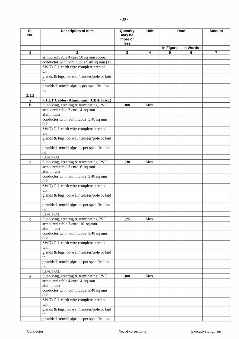
- 39 -
Contractor No. of corrections Executive Engineer
Sl. No.
Description of Item Quantity may be more or
less
Unit Rate Amount
In Figure In Words 1 2 3 4 5 6 7
armoured cable 4 core 50 sq mm copper
conductor with continuous 5.48 sq mm (12
SWG) G.I. earth wire complete erected
with
glands & lugs, on wall/ trusses/pole or laid
in
provided trench/ pipe as per specification
no.
2.1.2
a 7.1 LT Cables (Aluminum) (CB-LT/AL)
b Supplying, erecting & terminating PVC 300 Mtrs.
armoured cable 3 core 4 sq mm
aluminium
conductor with continuous 5.48 sq mm
(12
SWG) G.I. earth wire complete erected
with
glands & lugs, on wall/ trusses/pole or laid
in
provided trench/ pipe as per specification
no.
CB-LT/AL
c Supplying, erecting & terminating PVC 130 Mtrs.
armoured cable 3 core 6 sq mm
aluminium
conductor with continuous 5.48 sq mm
(12
SWG) G.I. earth wire complete erected
with
glands & lugs, on wall/ trusses/pole or laid
in
provided trench/ pipe as per specification
no.
CB-LT/AL
c Supplying, erecting & terminating PVC 125 Mtrs.
armoured cable 3 core 10 sq mm
aluminium
conductor with continuous 5.48 sq mm
(12
SWG) G.I. earth wire complete erected
with
glands & lugs, on wall/ trusses/pole or laid
in
provided trench/ pipe as per specification
no.
CB-LT/AL
e Supplying, erecting & terminating PVC 300 Mtrs.
armoured cable 4 core 4 sq mm
aluminium
conductor with continuous 5.48 sq mm
(12
SWG) G.I. earth wire complete erected
with
glands & lugs, on wall/ trusses/pole or laid
in
provided trench/ pipe as per specification

- 40 -
Contractor No. of corrections Executive Engineer
Sl. No.
Description of Item Quantity may be more or
less
Unit Rate Amount
In Figure In Words 1 2 3 4 5 6 7
no. CB-LT/AL
f Supplying, erecting & terminating PVC 125 Mtrs.
armoured cable 4 core 6 sq mm
aluminium
conductor with continuous 5.48 sq mm
(12
SWG) G.I. earth wire complete erected
with
glands & lugs, on wall/ trusses/pole or laid
in
provided trench/ pipe as per specification
no.
CB-LT/AL
g Supplying, erecting & terminating PVC 200 Mtrs.
armoured cable 4 core 10 sq mm
aluminium
conductor with continuous 5.48 sq mm
(12
SWG) G.I. earth wire complete erected
with
glands & lugs, on wall/ trusses/pole or laid
in
provided trench/ pipe as per specification
no.
CB-LT/AL
h Supplying, erecting & terminating PVC 250 Mtrs.
armoured cable 4 core 16 sq mm
aluminium
conductor with continuous 5.48 sq mm
(12
SWG) G.I. earth wire complete erected
with
glands & lugs, on wall/ trusses/pole or laid
in
provided trench/ pipe as per specification
no.
CB-LT/AL
i Supplying, erecting & terminating PVC 90 Mtrs.
armoured cable 3½ core 25 sq mm
aluminium conductor with continuous
5.48 sq
mm (12 SWG) G.I. earth wire complete
erected
with glands & lugs, on wall/ trusses/pole
or laid
in provided trench/ pipe as per
specification no.
CB-LT/AL
j Supplying, erecting & terminating PVC 80 Mtrs.
armoured cable 3½ core 35 sq mm
aluminium conductor with continuous
5.48 sq
mm (12 SWG) G.I. earth wire complete
erected

- 41 -
Contractor No. of corrections Executive Engineer
Sl. No.
Description of Item Quantity may be more or
less
Unit Rate Amount
In Figure In Words 1 2 3 4 5 6 7
with glands & lugs, on wall/ trusses/pole
or laid
in provided trench/ pipe as per
specification no.
CB-LT/AL
k Supplying, erecting & terminating PVC 75 Mtrs.
armoured cable 3½ core 50 sq mm
aluminium conductor with continuous
5.48 sq
mm (12 SWG) G.I. earth wire complete
erected
with glands & lugs, on wall/ trusses/pole
or laid
in provided trench/ pipe as per
specification no.
CB-LT/AL
l Supplying, erecting & terminating PVC 85 Mtrs.
armoured cable 3½ core 70 sq mm
aluminium conductor with continuous
8.35 sq
mm (10 SWG) G.I. earth wire complete
erected
with glands & lugs, on wall/ trusses/pole
or laid
in provided trench/ pipe as per
specification no.
CB-LT/AL
m upplying, erecting & terminating PVC 90 Mtrs.
armoured cable 3½ core 95 sq mm
aluminium conductor with continuous
8.35 sq
mm (10 SWG) G.I. earth wire complete
erected
with glands & lugs, on wall/ trusses/pole
or laid
in provided trench/ pipe as per
specification no.
CB-LT/AL
n Supplying, erecting & terminating PVC 90 Mtrs.
armoured cable 3½ core 120 sq mm
aluminium conductor with continuous
12.97
sq mm (8 SWG) G.I. earth wire complete
erected with glands & lugs, on wall/
trusses/pole
or laid in provided trench/ pipe as per
specification no. CB-LT/AL
o Supplying, erecting & terminating PVC 110 Mtrs.
armoured cable 3½ core 150 sq mm
aluminium conductor with continuous
12.97 sq
mm (8 SWG) G.I. earth wire complete
erected
with glands & lugs, on wall/ trusses/pole
or laid

- 42 -
Contractor No. of corrections Executive Engineer
Sl. No.
Description of Item Quantity may be more or
less
Unit Rate Amount
In Figure In Words 1 2 3 4 5 6 7
in provided trench/ pipe as per
specification no.
CB-LT/AL
p Supplying, erecting & terminating PVC 100 Mtrs.
armoured cable 1100 V. 3½ core 185 sq
mm
aluminium conductor with continuous
12.97
sq mm (8 SWG) G.I. earth wire complete
erected with glands & lugs, on wall/
trusses/pole
or laid in provided trench/ pipe as per
specification no. CB-LT/AL
q Supplying, erecting & terminating PVC 100 Mtrs.
armoured cable 3½core 240 sq mm
aluminium conductor with continuous
12.97 sq
mm (8 SWG) G.I. earth wire complete
erected
with glands & lugs, on wall/ trusses/pole
or laid
in provided trench/ pipe as per
specification no.
CB-LT/AL
r Supplying, erecting & terminating PVC 400 Mtrs.
armoured cable 3½ core 300 sq mm
aluminium conductor with continuous
12.97
sq mm (8 SWG) G.I. earth wire complete
erected with glands & lugs, on wall/
trusses/pole
or laid in provided trench/ pipe as per
specification no. CB-LT/AL
2.3 Electrical Work From Meter Room to
Office
2.3.1 Electrical Meter
Supply & installations of Meter
(Not in Electrical Contractor Scope)
2.3.2 Breakers / Isolators after Meter
General Specifications
Supply, installation, testing &
comissioning of MCB's / Isolators in
Metal boards in IP42 enclosure, as
follows:
3 Phase
CSR Base Specifications
a Supplying, erecting & marking TPMCB
40A to 55 Nos
63A in provided distribution board as per
specification No. SW-SWR/MCB
b Providing & erecting 3 Pole MCCB of 4 Nos
200A,415V capacity with S.C. rating 25
kA
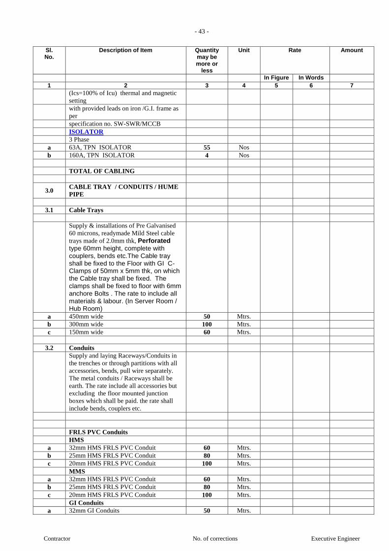
- 43 -
Contractor No. of corrections Executive Engineer
Sl. No.
Description of Item Quantity may be more or
less
Unit Rate Amount
In Figure In Words 1 2 3 4 5 6 7
(Ics=100% of Icu) thermal and magnetic
setting
with provided leads on iron /G.I. frame as
per
specification no. SW-SWR/MCCB
ISOLATOR
3 Phase
a 63A, TPN ISOLATOR 55 Nos
b 160A, TPN ISOLATOR 4 Nos
TOTAL OF CABLING
3.0 CABLE TRAY / CONDUITS / HUME
PIPE
3.1 Cable Trays
Supply & installations of Pre Galvanised
60 microns, readymade Mild Steel cable
trays made of 2.0mm thk, Perforated type 60mm height, complete with couplers, bends etc.The Cable tray shall be fixed to the Floor with GI C- Clamps of 50mm x 5mm thk, on which the Cable tray shall be fixed. The clamps shall be fixed to floor with 6mm anchore Bolts . The rate to include all materials & labour. (In Server Room / Hub Room)
a 450mm wide 50 Mtrs.
b 300mm wide 100 Mtrs.
c 150mm wide 60 Mtrs.
3.2 Conduits
Supply and laying Raceways/Conduits in
the trenches or through partitions with all
accessories, bends, pull wire separately.
The metal conduits / Raceways shall be
earth. The rate include all accessories but
excluding the floor mounted junction
boxes which shall be paid. the rate shall
include bends, couplers etc.
FRLS PVC Conduits
HMS
a 32mm HMS FRLS PVC Conduit 60 Mtrs.
b 25mm HMS FRLS PVC Conduit 80 Mtrs.
c 20mm HMS FRLS PVC Conduit 100 Mtrs.
MMS
a 32mm HMS FRLS PVC Conduit 60 Mtrs.
b 25mm HMS FRLS PVC Conduit 80 Mtrs.
c 20mm HMS FRLS PVC Conduit 100 Mtrs.
GI Conduits
a 32mm GI Conduits 50 Mtrs.
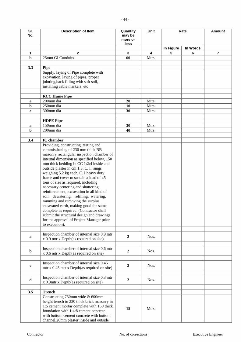
- 44 -
Contractor No. of corrections Executive Engineer
Sl. No.
Description of Item Quantity may be more or
less
Unit Rate Amount
In Figure In Words 1 2 3 4 5 6 7
b 25mm GI Conduits 60 Mtrs.
3.3 Pipe
Supply, laying of Pipe complete with
excavation, laying of pipes, proper
jointing,back filling with soft soil,
installing cable markers, etc
RCC Hume Pipe
a 200mm dia 20 Mtrs.
b 250mm dia 10 Mtrs.
c 300mm dia 30 Mtrs.
HDPE Pipe
a 150mm dia 30 Mtrs.
b 200mm dia 40 Mtrs.
3.4 IC chamber
Providing, constructing, testing and
commissioning of 230 mm thick BB
masonry rectangular inspection chamber of
internal dimension as specified below, 150
mm thick bedding in CC 1:2:4 inside and
outside plaster in cm 1:3, C. I. rungs
weighing 5.2 kg each, C. I heavy duty
frame and cover to sustain a load of 45
tons of size as required, including
necessary centering and shuttering,
reinforcement, excavation in all kind of
soil, dewatering, refilling, watering,
ramming and removing the surplus
excavated earth, making good the same
complete as required. (Contractor shall
submit the structural design and drawings
for the approval of Project Manager prior
to execution).
a Inspection chamber of internal size 0.9 mtr
x 0.9 mtr x Depth(as required on site) 2 Nos.
b Inspection chamber of internal size 0.6 mtr
x 0.6 mtr x Depth(as required on site) 2 Nos.
c Inspection chamber of internal size 0.45
mtr x 0.45 mtr x Depth(as required on site) 2 Nos.
d Inspection chamber of internal size 0.3 mtr
x 0.3mtr x Depth(as required on site) 2 Nos.
3.5 Trench
Constructing 750mm wide & 600mm
height trench in 230 thick brick masonry in
1:5 cement mortar complete with:150 thick
foundation with 1:4:8 cement concrete
with bottom cement concrete with bottom
channel.20mm plaster inside and outside
15 Mtrs.

- 45 -
Contractor No. of corrections Executive Engineer
Sl. No.
Description of Item Quantity may be more or
less
Unit Rate Amount
In Figure In Words 1 2 3 4 5 6 7
with 1:3 cement mortar.Running grating of
40 x 5 flat 25mm cc welded vertically in a
40 x 40 x 5 around frame, 50 x 50 x 6
angle runners on either side embedded in
masonry with holdfasts.generally meeting
the intents of the specifications and drgs.
RCC covers of Suitable size to be
provided on top in series for maintenance
purpose
TOTAL OF CABLE TRAY /
CONDUITS / HUME PIPE
4.0 POINT WIRING
Notes :
1) Rates for point wiring shall include
A) Supply & installation of conduits,
wires, junction boxes & accessories.
B) Supply & installation of Switches &
sockets .
C) Rate shall include cost of GI switch
Box, Modular Front Plate, Modular
Switches, ceiling rose & holder,
connectors etc.
D) The rate shall include cost of 10mm
MS hook mounted in ceiling slab. Rate to
include cost of dimmer & switch for
Chandelier point and Ceiling Fan point
E) Circuit wiring from MCB DBs to the
first switch boards OR looping to other
switch boxes shall be included as part of
primary, points for the `Rate'.
2) Rates for point wiring shall not
included
A) Payments for light fixtures will be
made separately as per the items given in
'Light Fixtures & Accessories'.
Cost of MCB for DB not to be included.
3) General note:
A) Unless otherwise specified, all wires in
point wiring shall be 2.5 Sq. mm Stranded
copper conductor 1.1 KV grade, I.S.I.
marked (P+N+E), Fire Retardant Low
Smoke (FRLs) insulated.
B)The Contractor can take more than one
circuit in the same conduit provided they
are of the same phase.
C) The size of conduit shall be decided
according to the number of wires in it as
per ISI & as specified. (Conduits size not
less than 20 mm dia)
D) Wires shall be colour coded (Red,
Yellow and Blue for Phases, Black for
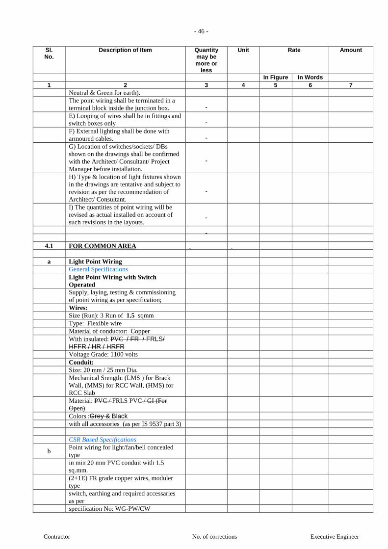
- 46 -
Contractor No. of corrections Executive Engineer
Sl. No.
Description of Item Quantity may be more or
less
Unit Rate Amount
In Figure In Words 1 2 3 4 5 6 7
Neutral & Green for earth).
The point wiring shall be terminated in a
terminal block inside the junction box.
E) Looping of wires shall be in fittings and
switch boxes only
F) External lighting shall be done with
armoured cables.
G) Location of switches/sockets/ DBs
shown on the drawings shall be confirmed
with the Architect/ Consultant/ Project
Manager before installation.
H) Type & location of light fixtures shown
in the drawings are tentative and subject to
revision as per the recommendation of
Architect/ Consultant.
I) The quantities of point wiring will be
revised as actual installed on account of
such revisions in the layouts.
4.1 FOR COMMON AREA
a Light Point Wiring
General Specifications
Light Point Wiring with Switch
Operated
Supply, laying, testing & commissioning
of point wiring as per specification;
Wires:
Size (Run): 3 Run of 1.5 sqmm
Type: Flexible wire
Material of conductor: Copper
With insulated: PVC / FR / FRLS/ HFFR / HR / HRFR
Voltage Grade: 1100 volts
Conduit:
Size: 20 mm / 25 mm Dia.
Mechanical Srength: (LMS ) for Brack
Wall, (MMS) for RCC Wall, (HMS) for
RCC Slab
Material: PVC / FRLS PVC / GI (For
Open)
Colors :Grey & Black
with all accessories (as per IS 9537 part 3)
CSR Based Specifications
b Point wiring for light/fan/bell concealed
type
in min 20 mm PVC conduit with 1.5
sq.mm.
(2+1E) FR grade copper wires, moduler
type
switch, earthing and required accessaries
as per
specification No: WG-PW/CW
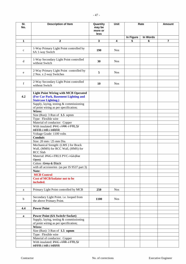
- 47 -
Contractor No. of corrections Executive Engineer
Sl. No.
Description of Item Quantity may be more or
less
Unit Rate Amount
In Figure In Words 1 2 3 4 5 6 7
c 1-Way Primary Light Point controlled by
6A 1-way Switch 190 Nos
d 1-Way Secondary Light Point controlled
without Switch 30 Nos
e 2-Way Primary Light Point controlled by
2 Nos. x 2-way Switches 5 Nos
f 2-Way Secondary Light Point controlled
without Switch 10 Nos
4.2 Light Point Wiring with MCB Operated
(For Car Park, Basement Lighting and
Staircase Lighting.)
Supply, laying, testing & commissioning
of point wiring as per specification;
Wires:
Size (Run): 3 Run of 1.5 sqmm
Type: Flexible wire
Material of conductor: Copper
With insulated: PVC / FR / FRLS/
HFFR / HR / HRFR
Voltage Grade: 1100 volts
Conduit:
Size: 20 mm / 25 mm Dia.
Mechanical Srength: (LMS ) for Brack
Wall, (MMS) for RCC Wall, (HMS) for
RCC Slab
Material: PVC / FRLS PVC / GI (For
Open)
Colors :Grey & Black
with all accessories (as per IS 9537 part 3)
Note:
MCB Control
Cost of MCB/Isolator not to be
included.
a Primary Light Point controlled by MCB 250 Nos
b Secondary Light Point. i.e. looped from
the above Primary Point. 1100 Nos
4.4 Power Point
a Power Point (6A Switch+Socket)
Supply, laying, testing & commissioning
of point wiring as per specification;
Wires:
Size (Run): 3 Run of 1.5 sqmm
Type: Flexible wire
Material of conductor: Copper
With insulated: PVC / FR / FRLS/ HFFR / HR / HRFR

- 48 -
Contractor No. of corrections Executive Engineer
Sl. No.
Description of Item Quantity may be more or
less
Unit Rate Amount
In Figure In Words 1 2 3 4 5 6 7
Voltage Grade: 1100 volts
Conduit:
Size: 20 mm / 25 mm Dia.
Mechanical Srength: (LMS ) for Brack
Wall, (MMS) for RCC Wall, (HMS) for
RCC Slab
Material: PVC / FRLS PVC / GI (For Open)
Colors :Grey & Black
with all accessories (as per IS 9537 part 3)
Switch+Socket:
Switch- 6 Amp.
Socket - 6 Amp. 2/3 pin
Switch+socket flush mounted in 1.6 mm
thick GI box 50 Nos
b Power Point (6 / 16 A Switch+ 16 Socket
)
Supply, laying, testing & commissioning
of point wiring as per specification;
Wires:
Size (Run): 3 Run of 2.5 sqmm
Type: Flexible wire
Material of conductor: Copper
With insulated: PVC / FR / FRLS/ HFFR / HR / HRFR
Voltage Grade: 1100 volts
Conduit:
Size: 20 mm / 25 mm Dia.
Mechanical Srength: (LMS ) for Brack
Wall, (MMS) for RCC Wall, (HMS) for
RCC Slab
Material: PVC / FRLS PVC / GI (For Open)
Colors :Grey & Black
with all accessories (as per IS 9537 part 3)
Switch+Socket:
Switch- 16 Amp.
Socket - 6 / 16 Amp. 3 pin
Switch+socket flush mounted in 1.6 mm
thick GI box 30 Nos
c Exhaust Fan
Supply, laying, testing & commissioning
of point wiring as per specification;
Wires:
Size (Run): 3 Run of 2.5 sqmm
Type: Flexible wire
Material of conductor: Copper
With insulated: PVC / FR / FRLS/ HFFR / HR / HRFR
Voltage Grade: 1100 volts
Conduit:
Size: 25 mm Dia.
Mechanical Srength: (LMS ) for Brack
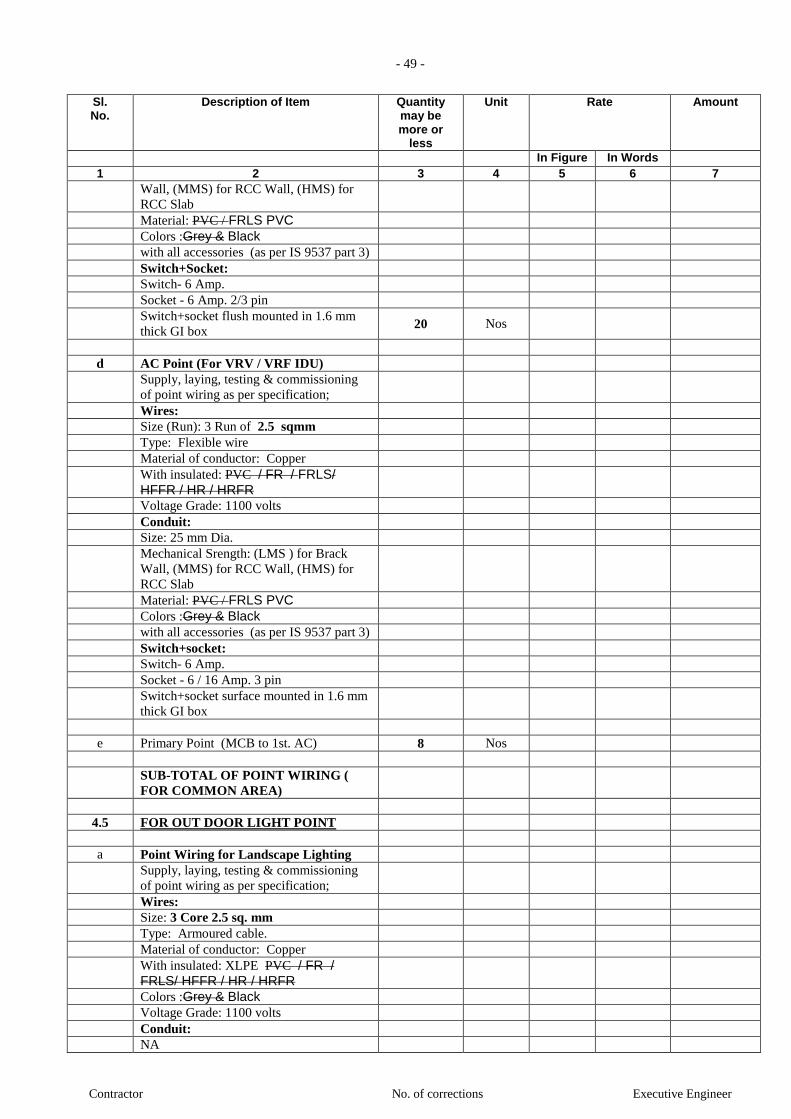
- 49 -
Contractor No. of corrections Executive Engineer
Sl. No.
Description of Item Quantity may be more or
less
Unit Rate Amount
In Figure In Words 1 2 3 4 5 6 7
Wall, (MMS) for RCC Wall, (HMS) for
RCC Slab Material: PVC / FRLS PVC
Colors :Grey & Black
with all accessories (as per IS 9537 part 3)
Switch+Socket:
Switch- 6 Amp.
Socket - 6 Amp. 2/3 pin
Switch+socket flush mounted in 1.6 mm
thick GI box 20 Nos
d AC Point (For VRV / VRF IDU)
Supply, laying, testing & commissioning
of point wiring as per specification;
Wires:
Size (Run): 3 Run of 2.5 sqmm
Type: Flexible wire
Material of conductor: Copper
With insulated: PVC / FR / FRLS/ HFFR / HR / HRFR
Voltage Grade: 1100 volts
Conduit:
Size: 25 mm Dia.
Mechanical Srength: (LMS ) for Brack
Wall, (MMS) for RCC Wall, (HMS) for
RCC Slab
Material: PVC / FRLS PVC
Colors :Grey & Black
with all accessories (as per IS 9537 part 3)
Switch+socket:
Switch- 6 Amp.
Socket - 6 / 16 Amp. 3 pin
Switch+socket surface mounted in 1.6 mm
thick GI box
e Primary Point (MCB to 1st. AC) 8 Nos
SUB-TOTAL OF POINT WIRING (
FOR COMMON AREA)
4.5 FOR OUT DOOR LIGHT POINT
a Point Wiring for Landscape Lighting
Supply, laying, testing & commissioning
of point wiring as per specification;
Wires:
Size: 3 Core 2.5 sq. mm
Type: Armoured cable.
Material of conductor: Copper
With insulated: XLPE PVC / FR / FRLS/ HFFR / HR / HRFR
Colors :Grey & Black
Voltage Grade: 1100 volts
Conduit:
NA
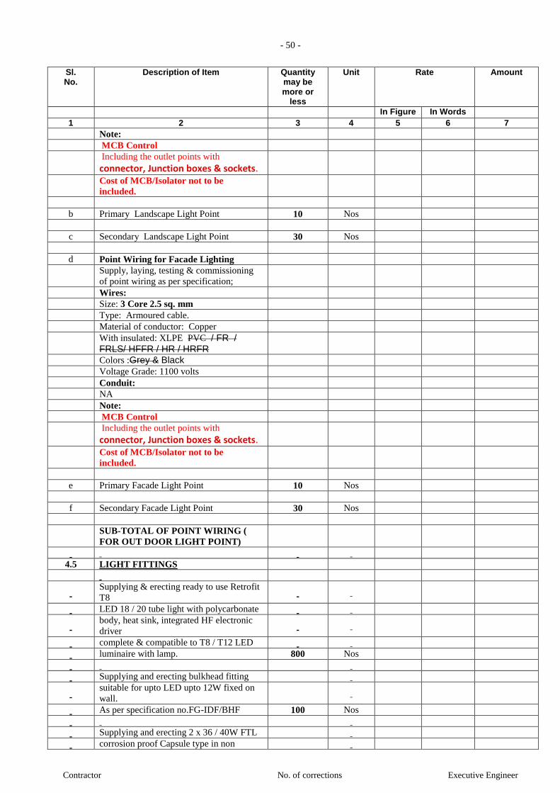
- 50 -
Contractor No. of corrections Executive Engineer
Sl. No.
Description of Item Quantity may be more or
less
Unit Rate Amount
In Figure In Words 1 2 3 4 5 6 7
Note:
MCB Control
Including the outlet points with
connector, Junction boxes & sockets.
Cost of MCB/Isolator not to be
included.
b Primary Landscape Light Point 10 Nos
c Secondary Landscape Light Point 30 Nos
d Point Wiring for Facade Lighting
Supply, laying, testing & commissioning
of point wiring as per specification;
Wires:
Size: 3 Core 2.5 sq. mm
Type: Armoured cable.
Material of conductor: Copper
With insulated: XLPE PVC / FR / FRLS/ HFFR / HR / HRFR
Colors :Grey & Black
Voltage Grade: 1100 volts
Conduit:
NA
Note:
MCB Control
Including the outlet points with
connector, Junction boxes & sockets.
Cost of MCB/Isolator not to be
included.
e Primary Facade Light Point 10 Nos
f Secondary Facade Light Point 30 Nos
SUB-TOTAL OF POINT WIRING (
FOR OUT DOOR LIGHT POINT)
4.5 LIGHT FITTINGS
Supplying & erecting ready to use Retrofit
T8
LED 18 / 20 tube light with polycarbonate
body, heat sink, integrated HF electronic
driver
complete & compatible to T8 / T12 LED
luminaire with lamp. 800 Nos
Supplying and erecting bulkhead fitting
suitable for upto LED upto 12W fixed on
wall.
As per specification no.FG-IDF/BHF 100 Nos
Supplying and erecting 2 x 36 / 40W FTL
corrosion proof Capsule type in non
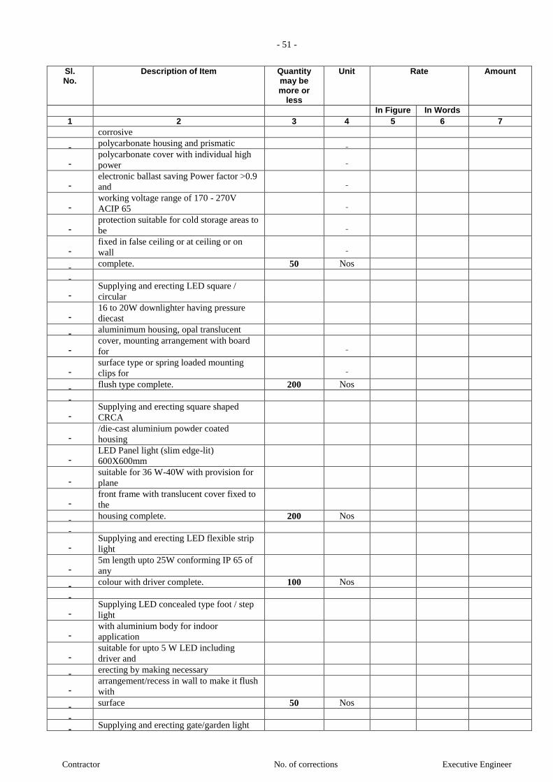
- 51 -
Contractor No. of corrections Executive Engineer
Sl. No.
Description of Item Quantity may be more or
less
Unit Rate Amount
In Figure In Words 1 2 3 4 5 6 7
corrosive polycarbonate housing and prismatic
polycarbonate cover with individual high
power
electronic ballast saving Power factor >0.9
and
working voltage range of 170 - 270V
ACIP 65
protection suitable for cold storage areas to
be
fixed in false ceiling or at ceiling or on
wall
complete. 50 Nos
Supplying and erecting LED square /
circular
16 to 20W downlighter having pressure
diecast
aluminimum housing, opal translucent
cover, mounting arrangement with board
for
surface type or spring loaded mounting
clips for
flush type complete. 200 Nos
Supplying and erecting square shaped
CRCA
/die-cast aluminium powder coated
housing
LED Panel light (slim edge-lit)
600X600mm
suitable for 36 W-40W with provision for
plane
front frame with translucent cover fixed to
the
housing complete. 200 Nos
Supplying and erecting LED flexible strip
light
5m length upto 25W conforming IP 65 of
any
colour with driver complete. 100 Nos
Supplying LED concealed type foot / step
light
with aluminium body for indoor
application
suitable for upto 5 W LED including
driver and
erecting by making necessary
arrangement/recess in wall to make it flush
with
surface 50 Nos
Supplying and erecting gate/garden light
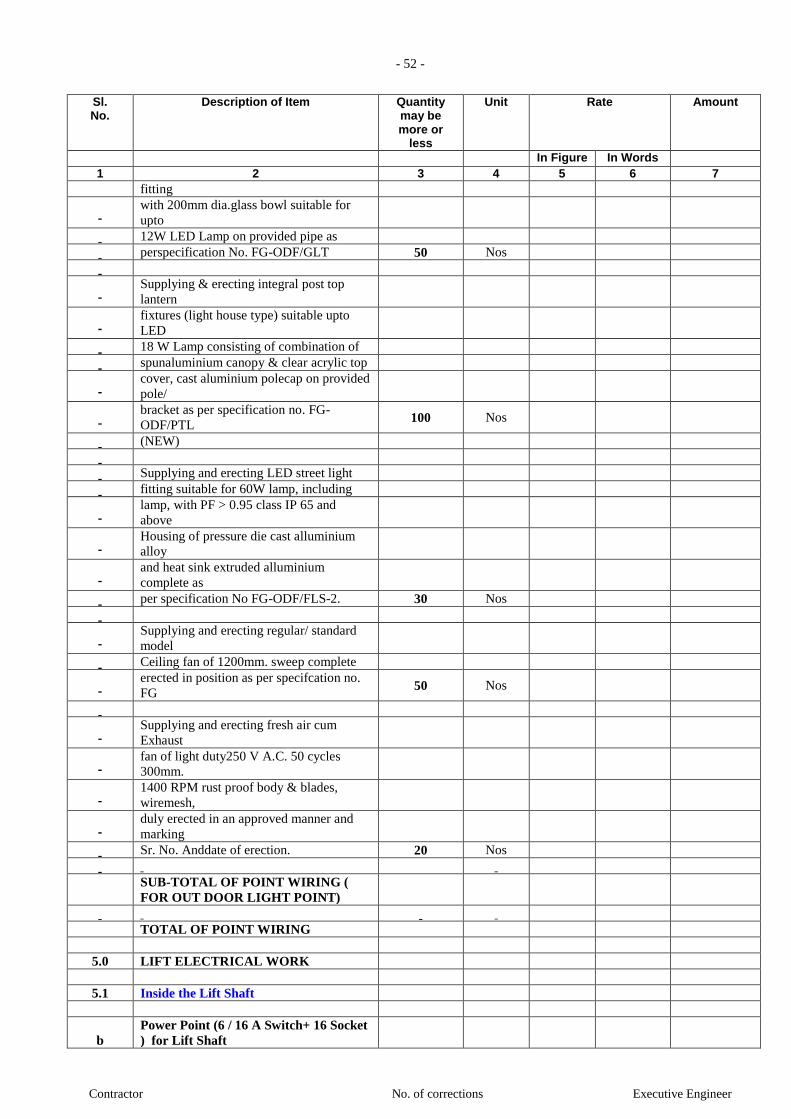
- 52 -
Contractor No. of corrections Executive Engineer
Sl. No.
Description of Item Quantity may be more or
less
Unit Rate Amount
In Figure In Words 1 2 3 4 5 6 7
fitting
with 200mm dia.glass bowl suitable for
upto
12W LED Lamp on provided pipe as
perspecification No. FG-ODF/GLT 50 Nos
Supplying & erecting integral post top
lantern
fixtures (light house type) suitable upto
LED
18 W Lamp consisting of combination of
spunaluminium canopy & clear acrylic top
cover, cast aluminium polecap on provided
pole/
bracket as per specification no. FG-
ODF/PTL 100 Nos
(NEW)
Supplying and erecting LED street light
fitting suitable for 60W lamp, including
lamp, with PF > 0.95 class IP 65 and
above
Housing of pressure die cast alluminium
alloy
and heat sink extruded alluminium
complete as
per specification No FG-ODF/FLS-2. 30 Nos
Supplying and erecting regular/ standard
model
Ceiling fan of 1200mm. sweep complete
erected in position as per specifcation no.
FG 50 Nos
Supplying and erecting fresh air cum
Exhaust
fan of light duty250 V A.C. 50 cycles
300mm.
1400 RPM rust proof body & blades,
wiremesh,
duly erected in an approved manner and
marking
Sr. No. Anddate of erection. 20 Nos
SUB-TOTAL OF POINT WIRING (
FOR OUT DOOR LIGHT POINT)
TOTAL OF POINT WIRING
5.0 LIFT ELECTRICAL WORK
5.1 Inside the Lift Shaft
b Power Point (6 / 16 A Switch+ 16 Socket
) for Lift Shaft
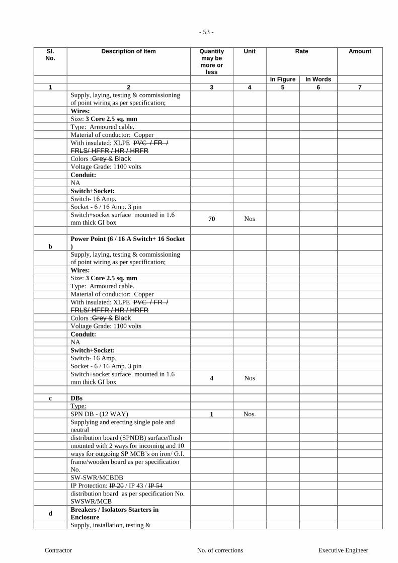
- 53 -
Contractor No. of corrections Executive Engineer
Sl. No.
Description of Item Quantity may be more or
less
Unit Rate Amount
In Figure In Words 1 2 3 4 5 6 7
Supply, laying, testing & commissioning
of point wiring as per specification;
Wires:
Size: 3 Core 2.5 sq. mm
Type: Armoured cable.
Material of conductor: Copper
With insulated: XLPE PVC / FR /
FRLS/ HFFR / HR / HRFR
Colors :Grey & Black
Voltage Grade: 1100 volts
Conduit:
NA
Switch+Socket:
Switch- 16 Amp.
Socket - 6 / 16 Amp. 3 pin
Switch+socket surface mounted in 1.6
mm thick GI box 70 Nos
b Power Point (6 / 16 A Switch+ 16 Socket
)
Supply, laying, testing & commissioning
of point wiring as per specification;
Wires:
Size: 3 Core 2.5 sq. mm
Type: Armoured cable.
Material of conductor: Copper
With insulated: XLPE PVC / FR /
FRLS/ HFFR / HR / HRFR
Colors :Grey & Black
Voltage Grade: 1100 volts
Conduit:
NA
Switch+Socket:
Switch- 16 Amp.
Socket - 6 / 16 Amp. 3 pin
Switch+socket surface mounted in 1.6
mm thick GI box 4 Nos
c DBs
Type:
SPN DB - (12 WAY) 1 Nos.
Supplying and erecting single pole and
neutral
distribution board (SPNDB) surface/flush
mounted with 2 ways for incoming and 10
ways for outgoing SP MCB’s on iron/ G.I.
frame/wooden board as per specification
No.
SW-SWR/MCBDB
IP Protection: IP 20 / IP 43 / IP 54
distribution board as per specification No.
SWSWR/MCB
d Breakers / Isolators Starters in
Enclosure
Supply, installation, testing &

- 54 -
Contractor No. of corrections Executive Engineer
Sl. No.
Description of Item Quantity may be more or
less
Unit Rate Amount
In Figure In Words 1 2 3 4 5 6 7
comissioning of MCB's / ELCB in Metal
boards, as follows: IP Protection: IP 20 / IP 43 / IP 54
Inside application:
63A MCB in Metal boards in IP42
enclosure 4 Nos
TOTAL OF LIFT ELECTRICAL
WORK
6.0 EARTHING SYSTEM
6.1 Earth Pit
a Maintenance free earthing electrode /
Chemical earthing
Supply, Installation, Testing and
commissioning of UL Certified / CPRI
Tested Maintenance Free Earthing
comprising of Electrode of 17.2 mm
diameter Low Carbon Steel with 250
micron Molecular Copper Bonded
Earthing Rod of Length 3m along with 25
kg Carbon Based environment friendly
back fill Ground Enhancing compound
required to fill up the
excavated earth with required quantity as
per specification no EA-MOBI
26 Sets
6.2 Earthing conductor
6.2.1 Earthing Strip
Providing and laying earthing conductors
of GI/Cu. strip including necessary
accessories, clamping to walls, cables etc.
as required and interconnection between
lengths as per specifications and as per
good installation practice. The rate shall
include all supports, accessories and
hardware necessary for proper installation.
Note:
Joints shall be lap welded/souldered &
coated with bitumen.
G.I. Strip
a 25 mm x 6 mm G.I. Strip 120 Mtrs.
b 40 mm x 6 mm G.I. Strip 50 Mtrs.
c 50 mm x 6 mm G.I. Strip 60 Mtrs.
CU. Strip
a 25 mm x 3 mm Cu. Strip 50 Mtrs.
b 50 mm x 3 mm Cu. Strip 40 Mtrs.
c 25 mm x 6 mm Cu. Strip 50 Mtrs.
d 50 mm x 6 mm Cu. Strip 30 Mtrs.
6.2.2 Earthing Wires
Supply & laying of Al / Copper conductor

- 55 -
Contractor No. of corrections Executive Engineer
Sl. No.
Description of Item Quantity may be more or
less
Unit Rate Amount
In Figure In Words 1 2 3 4 5 6 7
through PVC conduits of suitable sizes
thro' ducts,trays etc. The rates shall include
cost of all materials & accessories
including termination. AL. wires
a 8 SWG 50 Mtrs.
b 10 SWG 100 Mtrs.
CU wires
a 8 SWG 100 Mtrs.
b 10 SWG 40 Mtrs.
6.2.2 Earthing Cable
Supply & laying of single core flexible
PVC insulated Copper conductor through
PVC conduits of suitable sizes thro'
ducts,trays etc. The rates shall include cost
of all materials & accessories including
termination.
CU Cable
a Single Core 2.5 Sqmm Copper Flexible
cable without Conduit 150 Mtrs.
b Single Core 4 Sqmm Copper Flexible
cable without Conduit 250 Mtrs.
TOTAL OF EARTHING SYSTEM
7.0 LIGHTNING PROTECTION
7.1 Air Termination (As per Type of
Lightning Protection System)
A EARLY STREAMER SYSTEM
Lightning arrester type Controlled Early
Streamer Emission system. NFC17-102
Compliant. The unit should be equipped
with a central pick up rod made of tin
plated copper ensuring full electrical
continuity between the tip and the earth
point. The unit shall be fully autonomous,
collect energy from ambient electric field
with a lower series of electrodes, detect
lightning strikes and emit a steamer at the
right time (controlled emission). A tester
or remote testing facility should be
available for maintenance purpose.
Performances of the unit should have been
tested in High Voltage Laboratory (CPRI)
as well as in Real Lightning Conditions.
1 Nos.
7.2 Elevation Pole
Elevation pole made of GI with a dia. Of
35mm to 50mm with a thread at the top to
fix the unit. Base plate, mounting bracket,
clamps and all required fixing accessories
should also be supplied.
1 Nos.
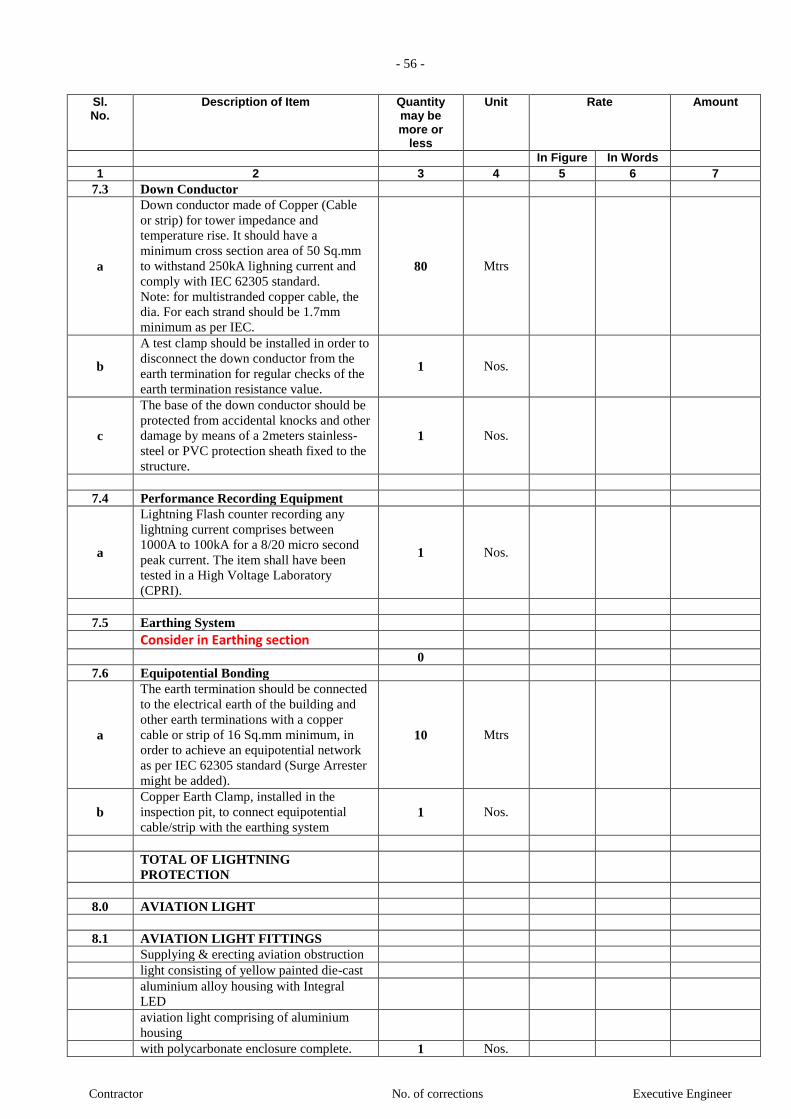
- 56 -
Contractor No. of corrections Executive Engineer
Sl. No.
Description of Item Quantity may be more or
less
Unit Rate Amount
In Figure In Words 1 2 3 4 5 6 7
7.3 Down Conductor
a
Down conductor made of Copper (Cable
or strip) for tower impedance and
temperature rise. It should have a
minimum cross section area of 50 Sq.mm
to withstand 250kA lighning current and
comply with IEC 62305 standard.
Note: for multistranded copper cable, the
dia. For each strand should be 1.7mm
minimum as per IEC.
80 Mtrs
b
A test clamp should be installed in order to
disconnect the down conductor from the
earth termination for regular checks of the
earth termination resistance value.
1 Nos.
c
The base of the down conductor should be
protected from accidental knocks and other
damage by means of a 2meters stainless-
steel or PVC protection sheath fixed to the
structure.
1 Nos.
7.4 Performance Recording Equipment
a
Lightning Flash counter recording any
lightning current comprises between
1000A to 100kA for a 8/20 micro second
peak current. The item shall have been
tested in a High Voltage Laboratory
(CPRI).
1 Nos.
7.5 Earthing System
Consider in Earthing section
0
7.6 Equipotential Bonding
a
The earth termination should be connected
to the electrical earth of the building and
other earth terminations with a copper
cable or strip of 16 Sq.mm minimum, in
order to achieve an equipotential network
as per IEC 62305 standard (Surge Arrester
might be added).
10 Mtrs
b Copper Earth Clamp, installed in the
inspection pit, to connect equipotential
cable/strip with the earthing system 1 Nos.
TOTAL OF LIGHTNING
PROTECTION
8.0 AVIATION LIGHT
8.1 AVIATION LIGHT FITTINGS
Supplying & erecting aviation obstruction
light consisting of yellow painted die-cast
aluminium alloy housing with Integral
LED
aviation light comprising of aluminium
housing
with polycarbonate enclosure complete. 1 Nos.
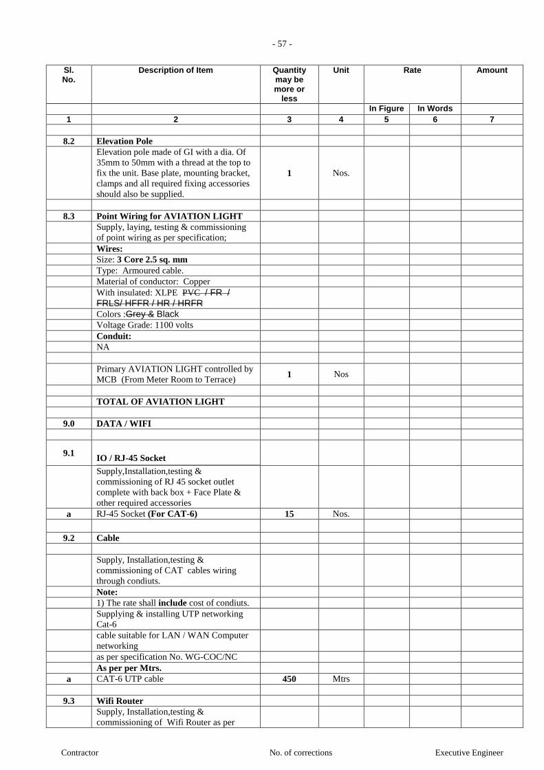
- 57 -
Contractor No. of corrections Executive Engineer
Sl. No.
Description of Item Quantity may be more or
less
Unit Rate Amount
In Figure In Words 1 2 3 4 5 6 7
8.2 Elevation Pole
Elevation pole made of GI with a dia. Of
35mm to 50mm with a thread at the top to
fix the unit. Base plate, mounting bracket,
clamps and all required fixing accessories
should also be supplied.
1 Nos.
8.3 Point Wiring for AVIATION LIGHT
Supply, laying, testing & commissioning
of point wiring as per specification;
Wires:
Size: 3 Core 2.5 sq. mm
Type: Armoured cable.
Material of conductor: Copper
With insulated: XLPE PVC / FR / FRLS/ HFFR / HR / HRFR
Colors :Grey & Black
Voltage Grade: 1100 volts
Conduit:
NA
Primary AVIATION LIGHT controlled by
MCB (From Meter Room to Terrace) 1 Nos
TOTAL OF AVIATION LIGHT
9.0 DATA / WIFI
9.1
IO / RJ-45 Socket
Supply,Installation,testing &
commissioning of RJ 45 socket outlet
complete with back box + Face Plate &
other required accessories
a RJ-45 Socket (For CAT-6) 15 Nos.
9.2 Cable
Supply, Installation,testing &
commissioning of CAT cables wiring
through condiuts.
Note:
1) The rate shall include cost of condiuts.
Supplying & installing UTP networking
Cat-6
cable suitable for LAN / WAN Computer
networking
as per specification No. WG-COC/NC
As per per Mtrs.
a CAT-6 UTP cable 450 Mtrs
9.3 Wifi Router
Supply, Installation,testing &
commissioning of Wifi Router as per

- 58 -
Contractor No. of corrections Executive Engineer
Sl. No.
Description of Item Quantity may be more or
less
Unit Rate Amount
In Figure In Words 1 2 3 4 5 6 7
specification
In Port:
Data
TELEPHONE
Out Port:
4 User 15 Nos.
9.4
Network Switch
Supplying, fixing, and configuring Web
Smart
Power over Ethernet Switch of 24 Ports on
provided rack or as directed as per
specification
No. WG-NWC/ENS 2 Nos.
TOTAL OF DATA / WIFI
10.0 TELEPHONE
10.1 Telephone / Intercom Point Wiring
Supply, laying, testing & commissioning
of point wiring as per specification;
Wires:
Size (Run): 1-Pair of 0.5 sqmm
Type: Telephone wire
Material of conductor: Copper
With insulated: PVC / FR / FRLS/ HFFR / HR / HRFR
Conduit:
Size: 20 mm / 25 mm Dia.
Mechanical Srength: (LMS ) for Brack
Wall, (MMS) for RCC Wall, (HMS) for
RCC Slab
Material: PVC / FRLS PVC / GI (For
Open)
Colors :Grey & Black
with all accessories (as per IS 9537 part 3)
RJ-11 Socket
RJ-11 the channel socket outlet point.
Switch Box
RJ 11 mounted in 1.6 mm thick GI box &
Modular Front Plate.
a Telephone Point Wiring 1 Nos
b Intercom Point Wiring 60 Nos
10.2
Telephone Cable
Supply, Installation,testing &

- 59 -
Contractor No. of corrections Executive Engineer
Sl. No.
Description of Item Quantity may be more or
less
Unit Rate Amount
In Figure In Words 1 2 3 4 5 6 7
commissioning of cables for telephone /
hook-up wire through PVC conduit with
pull box/ junction box & all accessories . Inside the Shaft
Cable
a
Supplying & erecting Jelly filled armoured
telephone cable 20 pair with 0.5 mm dia.
laid
in provided trench as per specification No.
WGTW 200 Mtrs
Conduit
b 20mm.dia. (MMS) FRLS PVC Conduit 200 Mtrs
From Shaft to LV DB
Cable
b Supplying & erecting telephone cable 2
pair 1500 Mtrs
with 0.5 mm dia. laid in provided PVC
casing /
conduit asper specification No. WG-TW
Conduit
d 20mm.dia. (MMS) PVC 300 Mtrs
10.3 MDF (Main Distribution Frames)
Supply, Installation,testing &
commissioning of MDF as per following
specification
a
10 Pair 15 Nos.
b
Supplying, erecting & commissioning
MDF
Box 60 x 60 pairs as per specification No.
WGTW 2 Nos.
10.4 EPABX
Supply, Installation,testing &
commissioning of EPABX as per
following specification
a
Supplying and installing, testing &
commissioning of Digital (Hybrid) type
EPABX of 8 x 20 (4 Digital+ 16 analog)
extensions suitable upto 120 extentions
48 - Hybrids / Analog Extensions
Expandable up to 48 Trunk & 128
Extensions by adding cabinets 2 Nos.
10.5 Extension Card
a Supply, Installation,testing &
commissioning of Extension Card as per
following specification
4 - CO/ Trunk
16 - Hybrids / Analog Extensions 2 Nos.

- 60 -
Contractor No. of corrections Executive Engineer
Sl. No.
Description of Item Quantity may be more or
less
Unit Rate Amount
In Figure In Words 1 2 3 4 5 6 7
TOTAL OF DATA & VOICE
11.0 TV SYSTEM
11.1 TV Point Wiring
Supply, laying, testing & commissioning
of point wiring as per specification;
Wires:
Size : RG-6 coaxial cable
Type: TV wire
Material of conductor: Copper
With insulated: PVC / FR / FRLS/ HFFR / HR / HRFR
Conduit:
Size: 20 mm / 25 mm Dia.
Mechanical Srength: (LMS ) for Brack
Wall, (MMS) for RCC Wall, (HMS) for
RCC Slab
Material: PVC / FRLS PVC / GI (For
Open)
Colors :Grey & Black
with all accessories (as per IS 9537 part 3)
RTV Socket
TV the channel socket outlet point.
Switch Box
TV Socket mounted in 1.6 mm thick GI
box & Modular Front Plate.
a TV Point Wiring 5 Nos
11.2 Cable
Supply and laying of RG 6 / 11 U tinned
copper co-axial cable with polythene
insulation with PVC Conduits 25mm/32
mm fixed to walls/Ceiling with Spacers &
saddles.
Inside the Shaft
a RG-11 coaxial cable 50 Mtrs
From Shaft to LV DB
b RG-6 coaxial cable 150 Mtrs
11.3 Splitters
Supply and installation of splitters in die
cast Aluminium casing.
Inside the Shaft
a 3-way splitters 2 Nos.
11.4 Antenna (TATA SKY or Other )
Supply and installation of Antenna.
Antenna 5 Nos.
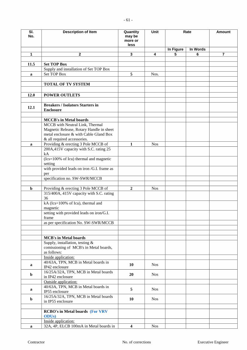
- 61 -
Contractor No. of corrections Executive Engineer
Sl. No.
Description of Item Quantity may be more or
less
Unit Rate Amount
In Figure In Words 1 2 3 4 5 6 7
11.5 Set TOP Box
Supply and installation of Set TOP Box
a Set TOP Box 5 Nos.
TOTAL OF TV SYSTEM
12.0 POWER OUTLETS
12.1 Breakers / Isolators Starters in
Enclosure
MCCB's in Metal boards
MCCB with Neutral Link, Thermal
Magnetic Release, Rotary Handle in sheet
metal enclosure & with Cable Gland Box
& all required accessories.
a Providing & erecting 3 Pole MCCB of 1 Nos
200A,415V capacity with S.C. rating 25
kA
(Ics=100% of Icu) thermal and magnetic
setting
with provided leads on iron /G.I. frame as
per
specification no. SW-SWR/MCCB
b Providing & erecting 3 Pole MCCB of 2 Nos
315/400A, 415V capacity with S.C. rating
36
kA (Ics=100% of Icu), thermal and
magnetic
setting with provided leads on iron/G.I.
frame
as per specification No. SW-SWR/MCCB
MCB's in Metal boards
Supply, installation, testing &
comissioning of MCB's in Metal boards,
as follows:
Inside application:
a 40/63A, TPN, MCB in Metal boards in
IP42 enclosure 10 Nos
b 16/25A/32A, TPN, MCB in Metal boards
in IP42 enclosure 20 Nos
Outside application:
a 40/63A, TPN, MCB in Metal boards in
IP55 enclosure 5 Nos
b 16/25A/32A, TPN, MCB in Metal boards
in IP55 enclosure 10 Nos
RCBO's in Metal boards (For VRV
ODUs)
Inside application:
a 32A, 4P, ELCB 100mA in Metal boards in 4 Nos
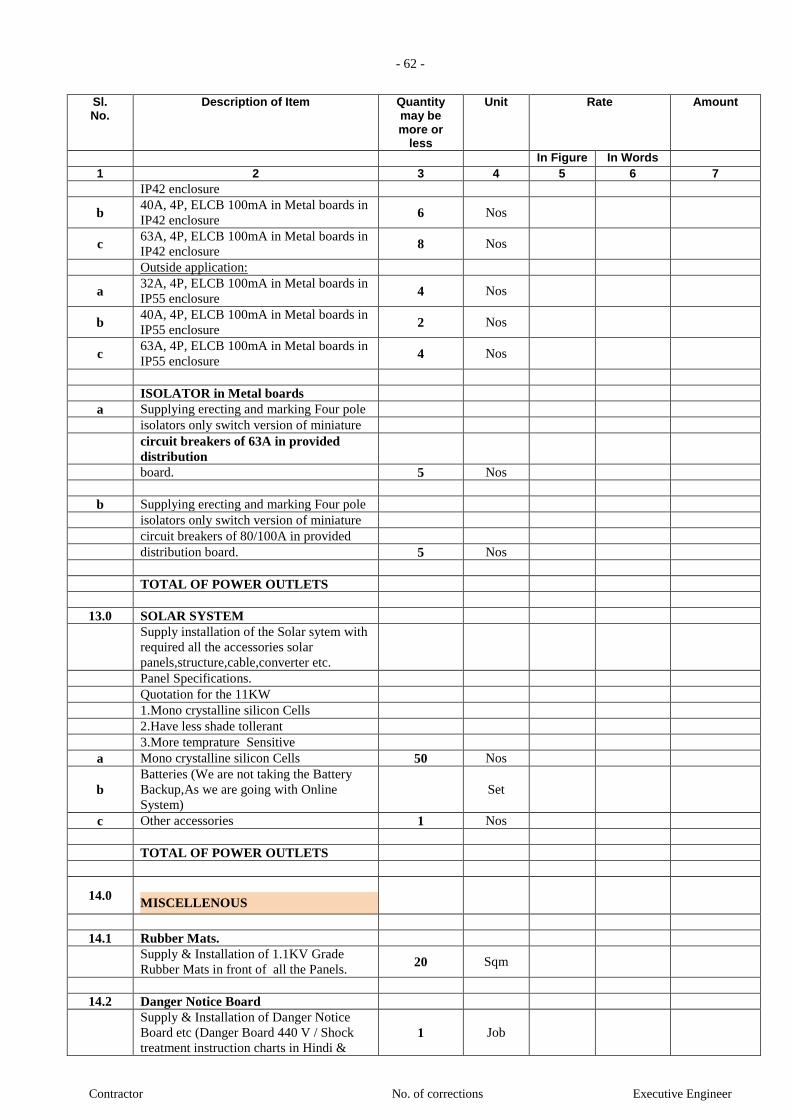
- 62 -
Contractor No. of corrections Executive Engineer
Sl. No.
Description of Item Quantity may be more or
less
Unit Rate Amount
In Figure In Words 1 2 3 4 5 6 7
IP42 enclosure
b 40A, 4P, ELCB 100mA in Metal boards in
IP42 enclosure 6 Nos
c 63A, 4P, ELCB 100mA in Metal boards in
IP42 enclosure 8 Nos
Outside application:
a 32A, 4P, ELCB 100mA in Metal boards in
IP55 enclosure 4 Nos
b 40A, 4P, ELCB 100mA in Metal boards in
IP55 enclosure 2 Nos
c 63A, 4P, ELCB 100mA in Metal boards in
IP55 enclosure 4 Nos
ISOLATOR in Metal boards
a Supplying erecting and marking Four pole
isolators only switch version of miniature
circuit breakers of 63A in provided
distribution
board. 5 Nos
b Supplying erecting and marking Four pole
isolators only switch version of miniature
circuit breakers of 80/100A in provided
distribution board. 5 Nos
TOTAL OF POWER OUTLETS
13.0 SOLAR SYSTEM
Supply installation of the Solar sytem with
required all the accessories solar
panels,structure,cable,converter etc.
Panel Specifications.
Quotation for the 11KW
1.Mono crystalline silicon Cells
2.Have less shade tollerant
3.More temprature Sensitive
a Mono crystalline silicon Cells 50 Nos
b Batteries (We are not taking the Battery
Backup,As we are going with Online
System) Set
c Other accessories 1 Nos
TOTAL OF POWER OUTLETS
14.0
MISCELLENOUS
14.1 Rubber Mats.
Supply & Installation of 1.1KV Grade
Rubber Mats in front of all the Panels. 20 Sqm
14.2 Danger Notice Board
Supply & Installation of Danger Notice
Board etc (Danger Board 440 V / Shock
treatment instruction charts in Hindi & 1 Job
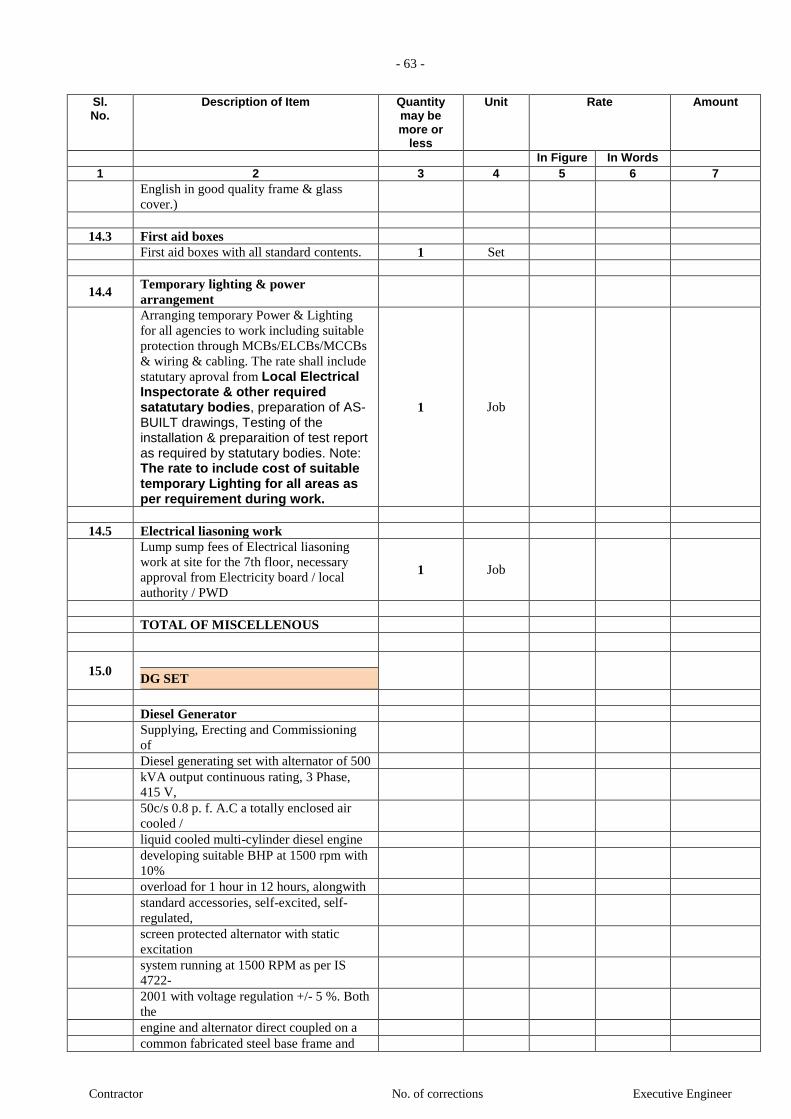
- 63 -
Contractor No. of corrections Executive Engineer
Sl. No.
Description of Item Quantity may be more or
less
Unit Rate Amount
In Figure In Words 1 2 3 4 5 6 7
English in good quality frame & glass
cover.)
14.3 First aid boxes
First aid boxes with all standard contents. 1 Set
14.4 Temporary lighting & power
arrangement
Arranging temporary Power & Lighting
for all agencies to work including suitable
protection through MCBs/ELCBs/MCCBs
& wiring & cabling. The rate shall include
statutary aproval from Local Electrical Inspectorate & other required satatutary bodies, preparation of AS-BUILT drawings, Testing of the installation & preparaition of test report as required by statutary bodies. Note: The rate to include cost of suitable temporary Lighting for all areas as per requirement during work.
1 Job
14.5 Electrical liasoning work
Lump sump fees of Electrical liasoning
work at site for the 7th floor, necessary
approval from Electricity board / local
authority / PWD
1 Job
TOTAL OF MISCELLENOUS
15.0
DG SET
Diesel Generator
Supplying, Erecting and Commissioning
of
Diesel generating set with alternator of 500
kVA output continuous rating, 3 Phase,
415 V,
50c/s 0.8 p. f. A.C a totally enclosed air
cooled /
liquid cooled multi-cylinder diesel engine
developing suitable BHP at 1500 rpm with
10%
overload for 1 hour in 12 hours, alongwith
standard accessories, self-excited, self-
regulated,
screen protected alternator with static
excitation
system running at 1500 RPM as per IS
4722-
2001 with voltage regulation +/- 5 %. Both
the
engine and alternator direct coupled on a
common fabricated steel base frame and

- 64 -
Contractor No. of corrections Executive Engineer
Sl. No.
Description of Item Quantity may be more or
less
Unit Rate Amount
In Figure In Words 1 2 3 4 5 6 7
mounted on anti-vibrating pads with
standard
control panel comprising of meters,
switchgears,
indicators connected with suitable
wires/cables,
the complete set enclosed in composite
Acoustic
enclosure as fully assembled integral unit
made
of 16 SWG CRCA Sheet, sound absorbing
material to restrict sound level upto 75 dB
at 1.0
m, provided with first filling of oil, diesel
etc.
and obtaining necessary approval from
Electrical Inspector as per specification no.
GEN-DG
Each 3405391 16017 3421408
Note:- 1) DG Set rating for altitudes more
than 150
m above
mean sea level shall be de-rated at 3.5 %
for
every 300 m above 150 m mean sea level.
2) In case of new DG set, if AMF/SYNC
panel
is to be used in lieu of standard panel,
reduce
rate by 10% of the cost of material of new
AMF panel/SYNC panel.
3) For all the Engines, the emission
standards/norms shall meet applicable
polution control board norms as amended
by
Government. 2 Nos
AMF panel
Supplying, erecting, testing and
commissioning
of Microprocessor based AMF panel
suitable
for Diesel Generating Set of upto 500 kVA
capacity Single/Three phase, 230/415
Volts,
50Hz A.C. with all standard features,
safeties etc
as per specification no. GEN-AMF. 2 Nos
Sychronizing Panel
Supplying, erecting, testing and
commissioning
of Microprocessor based Generator
Control
Unit (Synchronization panel) panel
suitable for
Diesel Generating Set of 500 kVA

- 65 -
Contractor No. of corrections Executive Engineer
Sl. No.
Description of Item Quantity may be more or
less
Unit Rate Amount
In Figure In Words 1 2 3 4 5 6 7
capacity
Three phase, 415 Volts, 50Hz A.C. with
all
standard features and safeties etc as per
specification no. GEN-SYNC. 1 Nos
TOTAL OF DG SET
8.0 PLUMBING WORK
A INTERNAL WATER SUPPLY SYSTEM:
1 Work within Toilet/Pantry/Kitchen area Concealed piping (Water Supply Domestic)
CPVC Pipe (Chlorinated Polyvinyl Chloride)
SDR 11: Pipes to be used from 1/2 Inch to 2 Inch (7 Bar @ 82 Deg C and 28 Bar @ 23 Deg C)
Schedule 80: Pipe to be used from 2-1/2 Inch to 6 Inch.
Providing and fixing CPVC (Chlorinated
Poly Vinyl Chloride) water supply pipes .
Pipes shall be joined using solvent welded
CPVC fittings i.e. Tees, Elbows, Couplers,
Unions, Reducers, brushings etc. including
transition fittings (connection between
CPVC & metal pipe/GI) i.e. Brass
Adaptors (both Male & Female threaded)
conforming to ASTM D-2846. ASTM
F441 with only CPVC solvent cement
conforming to ASTM F-493. All
termination points for installation of
faucets shall have brass termination
fittings. Installation shall be to as per
Technical Manual of manufacturer of
pipes & fittings. Cost shall be inclusive of
insulation for hot water pipe. and also Cost
shall be inclusive of pipe length whether
Geyser installed in Shower area or in
plumbing shaft.
Cost shall be inclusive of Making maximum of 7.5 x 7.5 cm chase in wall
and floors for the pipe, making good the
same by using 1:2 cement mortar over the
wire mesh and providing protection to
embedded pipes and fittings (in wall
chase) by wrapping two layers of 400
micron polythene sheet including proper
overlaps on joints complete as required.
a 25 mm dia 260 Rmt
b 20 mm dia 1255 Rmt
c 15 mm dia 790 Rmt
2 Work within Toilet/Pantry/Kitchen area Concealed piping (Water Supply Flushing)
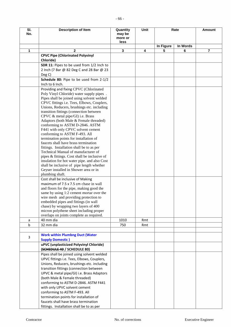
- 66 -
Contractor No. of corrections Executive Engineer
Sl. No.
Description of Item Quantity may be more or
less
Unit Rate Amount
In Figure In Words 1 2 3 4 5 6 7
CPVC Pipe (Chlorinated Polyvinyl Chloride)
SDR 11: Pipes to be used from 1/2 Inch to 2 Inch (7 Bar @ 82 Deg C and 28 Bar @ 23 Deg C)
Schedule 80: Pipe to be used from 2-1/2 Inch to 6 Inch.
Providing and fixing CPVC (Chlorinated
Poly Vinyl Chloride) water supply pipes .
Pipes shall be joined using solvent welded
CPVC fittings i.e. Tees, Elbows, Couplers,
Unions, Reducers, brushings etc. including
transition fittings (connection between
CPVC & metal pipe/GI) i.e. Brass
Adaptors (both Male & Female threaded)
conforming to ASTM D-2846. ASTM
F441 with only CPVC solvent cement
conforming to ASTM F-493. All
termination points for installation of
faucets shall have brass termination
fittings. Installation shall be to as per
Technical Manual of manufacturer of
pipes & fittings. Cost shall be inclusive of
insulation for hot water pipe. and also Cost
shall be inclusive of pipe length whether
Geyser installed in Shower area or in
plumbing shaft.
Cost shall be inclusive of Making maximum of 7.5 x 7.5 cm chase in wall
and floors for the pipe, making good the
same by using 1:2 cement mortar over the
wire mesh and providing protection to
embedded pipes and fittings (in wall
chase) by wrapping two layers of 400
micron polythene sheet including proper
overlaps on joints complete as required.
a 40 mm dia 1010 Rmt
b 32 mm dia 750 Rmt
3 Work within Plumbng Duct (Water Supply Domestic )
uPVC (unplasticized Polyvinyl Chloride) (SCHEDULE 40 / SCHEDULE 80)
Pipes shall be joined using solvent welded UPVC fittings i.e. Tees, Elbows, Couplers, Unions, Reducers, brushings etc. including transition fittings (connection between UPVC & metal pipe/GI) i.e. Brass Adaptors (both Male & Female threaded) conforming to ASTM D-2846. ASTM F441 with only UPVC solvent cement conforming to ASTM F-493. All termination points for installation of faucets shall have brass termination fittings. Installation shall be to as per

- 67 -
Contractor No. of corrections Executive Engineer
Sl. No.
Description of Item Quantity may be more or
less
Unit Rate Amount
In Figure In Words 1 2 3 4 5 6 7
Technical Manual of manufacturer of pipes & fittings. Including ball valve, Butterfly valve, PRV,with all fittings i.e. Tee, Elbow, flanges / union, rubber gasket, nuts, bolts, jointing material, washers & painting complete as required.
Cost shall be inclusive of Fixing/supporting the pipes (& fittings) at wall/ceiling level supported by galvanized clamps, hangers etc, as per specification. Exposed pipes to be painted of legends with direction arrow. GI pipe sleeves suitable higher size shall be provided wherever the pipes are crossing the fire rated walls / floors slab and sealing the sleeves with glass wool in between and fire sealant compound at either end all as per Project Manager's / Consultant requirement. All termination points for installation of faucets shall have brass termination fittings. Installation shall be to as per Technical Manual of manufacturer of pipes & fittings.
a 50 mm dia 48 Rmt
b 40 mm dia 96 Rmt
c 32 mm dia 102 Rmt
d 25 mm dia 376 Rmt
4 Work within Plumbng Duct (Water Supply Flushing)
uPVC (unplasticized Polyvinyl Chloride) (SCHEDULE 40 / SCHEDULE 80)
Pipes shall be joined using solvent welded UPVC fittings i.e. Tees, Elbows, Couplers, Unions, Reducers, brushings etc. including transition fittings (connection between UPVC & metal pipe/GI) i.e. Brass Adaptors (both Male & Female threaded) conforming to ASTM D-2846. ASTM F441 with only UPVC solvent cement conforming to ASTM F-493. All termination points for installation of faucets shall have brass termination fittings. Installation shall be to as per Technical Manual of manufacturer of pipes & fittings. Including ball valve, Butterfly valve, PRV,with all fittings i.e. Tee, Elbow, flanges / union, rubber gasket, nuts, bolts, jointing material, washers & painting complete as required.
Cost shall be inclusive of Fixing/supporting the pipes (& fittings) at wall/ceiling level supported by galvanized clamps, hangers etc, as per specification. Exposed pipes to

- 68 -
Contractor No. of corrections Executive Engineer
Sl. No.
Description of Item Quantity may be more or
less
Unit Rate Amount
In Figure In Words 1 2 3 4 5 6 7
be painted of legends with direction arrow. GI pipe sleeves suitable higher size shall be provided wherever the pipes are crossing the fire rated walls / floors slab and sealing the sleeves with glass wool in between and fire sealant compound at either end all as per Project Manager's / Consultant requirement. All termination points for installation of faucets shall have brass termination fittings. Installation shall be to as per Technical Manual of manufacturer of pipes & fittings.
a 65 mm dia 96 Rmt
b 50 mm dia 96 Rmt
c 40 mm dia 378 Rmt
d 32 mm dia 3 Rmt
5 Work within Terrace Loop (Water Supply Domestic )
uPVC (unplasticized Polyvinyl Chloride) (SCHEDULE 40 / SCHEDULE 80)
Pipes shall be joined using solvent welded UPVC fittings i.e. Tees, Elbows, Couplers, Unions, Reducers, brushings etc. including transition fittings (connection between UPVC & metal pipe/GI) i.e. Brass Adaptors (both Male & Female threaded) conforming to ASTM D-2846. ASTM F441 with only UPVC solvent cement conforming to ASTM F-493. All termination points for installation of faucets shall have brass termination fittings. Installation shall be to as per Technical Manual of manufacturer of pipes & fittings. Including ball valve, Butterfly valve, PRV,with all fittings i.e. Tee, Elbow, flanges / union, rubber gasket, nuts, bolts, jointing material, washers & painting complete as required.
Cost shall be inclusive of Fixing/supporting the pipes (& fittings) at wall/ceiling level supported by galvanized clamps, hangers etc, as per specification. Exposed pipes to be painted of legends with direction arrow. GI pipe sleeves suitable higher size shall be provided wherever the pipes are crossing the fire rated walls / floors slab and sealing the sleeves with glass wool in between and fire sealant compound at either end all as per Project Manager's / Consultant requirement. All termination points for installation of faucets shall have brass termination fittings. Installation

- 69 -
Contractor No. of corrections Executive Engineer
Sl. No.
Description of Item Quantity may be more or
less
Unit Rate Amount
In Figure In Words 1 2 3 4 5 6 7
shall be to as per Technical Manual of manufacturer of pipes & fittings.
a 80 mm dia 125 Rmt
6 Work within Terrace Loop (Water Supply Flushing)
uPVC (unplasticized Polyvinyl Chloride) (SCHEDULE 40 / SCHEDULE 80)
Pipes shall be joined using solvent welded UPVC fittings i.e. Tees, Elbows, Couplers, Unions, Reducers, brushings etc. including transition fittings (connection between UPVC & metal pipe/GI) i.e. Brass Adaptors (both Male & Female threaded) conforming to ASTM D-2846. ASTM F441 with only UPVC solvent cement conforming to ASTM F-493. All termination points for installation of faucets shall have brass termination fittings. Installation shall be to as per Technical Manual of manufacturer of pipes & fittings. Including ball valve, Butterfly valve, PRV,with all fittings i.e. Tee, Elbow, flanges / union, rubber gasket, nuts, bolts, jointing material, washers & painting complete as required.
Cost shall be inclusive of Fixing/supporting the pipes (& fittings) at wall/ceiling level supported by galvanized clamps, hangers etc, as per specification. Exposed pipes to be painted of legends with direction arrow. GI pipe sleeves suitable higher size shall be provided wherever the pipes are crossing the fire rated walls / floors slab and sealing the sleeves with glass wool in between and fire sealant compound at either end all as per Project Manager's / Consultant requirement. All termination points for installation of faucets shall have brass termination fittings. Installation shall be to as per Technical Manual of manufacturer of pipes & fittings.
a 80 mm dia 125 Rmt
7 VALVES in Terrace & Plumbing Duct (For Domestic and Flushing)
7.1 Ball Valve
Providing and fixing ball valve including
flanges / union, etc. complete as required.
Tested pressure = 15 Kg / Sqcm
Material : Brass
a 20 mm n.b 4 NOS.
b 25 mm n.b 45 NOS.

- 70 -
Contractor No. of corrections Executive Engineer
Sl. No.
Description of Item Quantity may be more or
less
Unit Rate Amount
In Figure In Words 1 2 3 4 5 6 7
c 32 mm n.b 4 NOS.
d 40 mm n.b 45 NOS.
e 50 mm n.b 4 NOS.
7.2 Butterfly Valve (Terrace Floor)
Providing & fixing butterfly valve (Body : Grey Cast Iron, Shaft : SS, Disc : SG Iron (Rilson coated), Liner : HT - EPDM) (upto 150mm dia with hand lever operation & above with gear box operation). Including rubber gasket, flanges, nuts, bolts, washers & painting complete as required.
Tested pressure = 15 Kg / Sqcm
Material : Cast Iron
a 65 mm n.b 4 NOS.
7.3 Air Vent valve (Terrace Floor PIPE LOOP)
Providing & fixing Auto Air vent for cold
water supply risers.
Tested pressure = 15 Kg / Sqcm
Material : Cast Iron
a 15 mm n.b 8 NOS.
7.4 P.R.V.
Providing and fixing Pressure Reducing valves complete as directed by engineer-in-charge. Contractor to set pressure as per instructions from consultant during execution.
Note: Set of P.R.V. of including 5 nos. x Ball / Butterfly Valve + 2 nos. x P.R.V.
Tested pressure = 25 Kg / Sqcm
Material : Forged Brass / Bronze
a 40 mm n.b 5 NOS.
b 50 mm n.b 3 NOS.
c 65 mm n.b 6 NOS.
SUB-TOTAL (Internal Water Supply System)
B INTERNAL SEWAGE DRAINAGE SYSTEM:
Work with in TOILET / Kitchen
1 UPVC Floor traps (plain / multi)
Supply, Installation, Testing and Commissioning
of upvc Floor traps (plain / multi) of self cleansing design
with water seal not less than 25mm
with or without vent, including setting the trap
in cement concrete M-15 as per

- 71 -
Contractor No. of corrections Executive Engineer
Sl. No.
Description of Item Quantity may be more or
less
Unit Rate Amount
In Figure In Words 1 2 3 4 5 6 7
specifications etc. complete.
Rate to include making of opening in floor, marble / tiles, for fixing
1.1 Floor traps (for Toilet / Kitchen)
a Trap with 110mm inlet & 75mm outlet. 150 NOS.
1.2 Multifloor traps (for Toilet / Kitchen)
a Trap with 110mm inlet & 75mm outlet. 200 NOS.
2 SWR PVC pipes (Type-B) (For Pipes in Toilets /Kitchen Area)
Supply, Installation, Testing and Commissioning of UPVC- SWR pipes confirming
to IS : 13592, and confirming to IS : 4985 (Pipe Class III - 6 kg / sq.cm)
and all necessary fittings such as 45 or 90 deg. bends, Tee's, Y's, including
solvent cement jointing and testing with setting
the pipes in cement concrete M-15 as per specifications
a 50 dia (Type B) 750 Rmt
b 75 dia (Type B) 1000 Rmt
c 100 dia (Type B) 750 Rmt
Work with in plumbing duct
3 SWR PVC pipes (Typ-B) (For Pipes In Shafts, Soil, Waste, Vent, etc.)
Supply Installation Testing and Commissioning
SWR- UPVC pipes and all necessary fittings such
as 45 or 90 deg. bends, Tee's, Y's, Cowls including fixing
of pipe support with PVC coated GI clamps on
GI brackets and ring jointing with testing of pipes and
making the joints leak proof and as directed by
Engineer in charge etc, complete
a 75 dia (Type B) 336 Rmt
b 100 dia (Type B) 336 Rmt
c 150 dia (Type B) 336 Rmt
Work for Diverted Pipe
4 Work within Basement Toilets & Ground Toilet to STP (BY PUMP)
uPVC (unplasticized Polyvinyl Chloride) (SCHEDULE 40 / SCHEDULE 80)
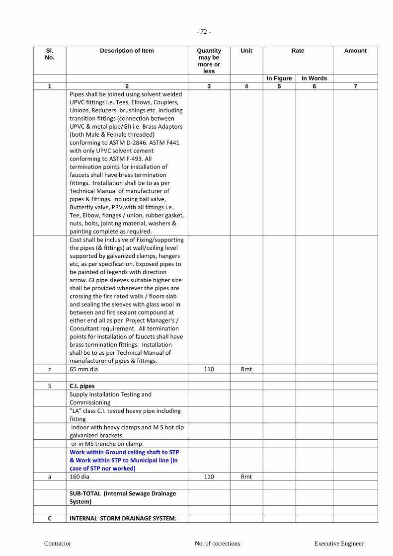
- 72 -
Contractor No. of corrections Executive Engineer
Sl. No.
Description of Item Quantity may be more or
less
Unit Rate Amount
In Figure In Words 1 2 3 4 5 6 7
Pipes shall be joined using solvent welded UPVC fittings i.e. Tees, Elbows, Couplers, Unions, Reducers, brushings etc. including transition fittings (connection between UPVC & metal pipe/GI) i.e. Brass Adaptors (both Male & Female threaded) conforming to ASTM D-2846. ASTM F441 with only UPVC solvent cement conforming to ASTM F-493. All termination points for installation of faucets shall have brass termination fittings. Installation shall be to as per Technical Manual of manufacturer of pipes & fittings. Including ball valve, Butterfly valve, PRV,with all fittings i.e. Tee, Elbow, flanges / union, rubber gasket, nuts, bolts, jointing material, washers & painting complete as required.
Cost shall be inclusive of Fixing/supporting the pipes (& fittings) at wall/ceiling level supported by galvanized clamps, hangers etc, as per specification. Exposed pipes to be painted of legends with direction arrow. GI pipe sleeves suitable higher size shall be provided wherever the pipes are crossing the fire rated walls / floors slab and sealing the sleeves with glass wool in between and fire sealant compound at either end all as per Project Manager's / Consultant requirement. All termination points for installation of faucets shall have brass termination fittings. Installation shall be to as per Technical Manual of manufacturer of pipes & fittings.
c 65 mm dia 110 Rmt
5 C.I. pipes
Supply Installation Testing and Commissioning
"LA" class C.I. tested heavy pipe including fitting
indoor with heavy clamps and M S hot dip galvanized brackets
or in MS trenche on clamp.
Work within Ground ceiling shaft to STP & Work within STP to Municipal line (in case of STP nor worked)
a 160 dia 110 Rmt
SUB-TOTAL (Internal Sewage Drainage System)
C INTERNAL STORM DRAINAGE SYSTEM:
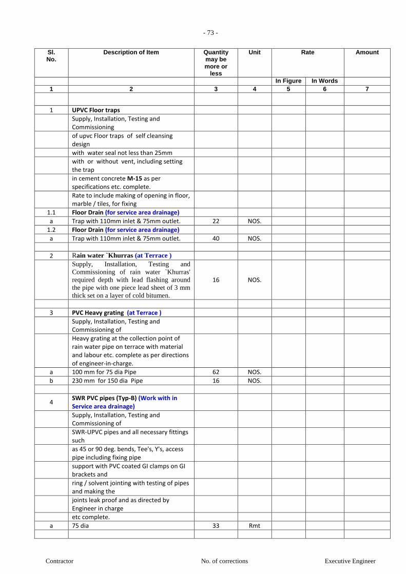
- 73 -
Contractor No. of corrections Executive Engineer
Sl. No.
Description of Item Quantity may be more or
less
Unit Rate Amount
In Figure In Words 1 2 3 4 5 6 7
1 UPVC Floor traps
Supply, Installation, Testing and Commissioning
of upvc Floor traps of self cleansing design
with water seal not less than 25mm
with or without vent, including setting the trap
in cement concrete M-15 as per specifications etc. complete.
Rate to include making of opening in floor, marble / tiles, for fixing
1.1 Floor Drain (for service area drainage)
a Trap with 110mm inlet & 75mm outlet. 22 NOS.
1.2 Floor Drain (for service area drainage)
a Trap with 110mm inlet & 75mm outlet. 40 NOS.
2 Rain water `Khurras (at Terrace )
Supply, Installation, Testing and
Commissioning of rain water `Khurras'
required depth with lead flashing around
the pipe with one piece lead sheet of 3 mm
thick set on a layer of cold bitumen.
16 NOS.
3 PVC Heavy grating (at Terrace )
Supply, Installation, Testing and Commissioning of
Heavy grating at the collection point of rain water pipe on terrace with material and labour etc. complete as per directions of engineer-in-charge.
a 100 mm for 75 dia Pipe 62 NOS.
b 230 mm for 150 dia Pipe 16 NOS.
4 SWR PVC pipes (Typ-B) (Work with in Service area drainage)
Supply, Installation, Testing and Commissioning of
SWR-UPVC pipes and all necessary fittings such
as 45 or 90 deg. bends, Tee's, Y's, access pipe including fixing pipe
support with PVC coated GI clamps on GI brackets and
ring / solvent jointing with testing of pipes and making the
joints leak proof and as directed by Engineer in charge
etc complete.
a 75 dia 33 Rmt

- 74 -
Contractor No. of corrections Executive Engineer
Sl. No.
Description of Item Quantity may be more or
less
Unit Rate Amount
In Figure In Words 1 2 3 4 5 6 7
5 SWR PVC pipes (Typ-B) (Work with in plumbing duct)
Supply, Installation, Testing and Commissioning of
SWR-UPVC pipes and all necessary fittings such
as 45 or 90 deg. bends, Tee's, Y's, access pipe including fixing pipe
support with PVC coated GI clamps on GI brackets and
ring / solvent jointing with testing of pipes and making the
joints leak proof and as directed by Engineer in charge
etc complete.
a 150 dia 1392 Rmt
6 SWR PVC pipes (Typ-B) (Work with in Basement Floor drainage)
Supply, Installation, Testing and Commissioning of
SWR-UPVC pipes and all necessary fittings such
as 45 or 90 deg. bends, Tee's, Y's, access pipe including fixing pipe
support with PVC coated GI clamps on GI brackets and
ring / solvent jointing with testing of pipes and making the
joints leak proof and as directed by Engineer in charge
etc complete.
a 75 dia 260 Rmt
Work for Diverted Pipe
7 C.I. pipes (Work within Basement Ceiling To Ground Chamber)
Supply Installation Testing and Commissioning
"LA" class C.I. tested heavy pipe including fitting
indoor with heavy clamps and M S hot dip galvanized brackets
or in MS trenche on clamp.
a 210 dia 300 Rmt
8 Work within 3rd Basement to ground for Car Pit, Sump & Plumbing shaft drainage (BY PUMP)
uPVC (unplasticized Polyvinyl Chloride) (SCHEDULE 40 / SCHEDULE 80)
Pipes shall be joined using solvent welded

- 75 -
Contractor No. of corrections Executive Engineer
Sl. No.
Description of Item Quantity may be more or
less
Unit Rate Amount
In Figure In Words 1 2 3 4 5 6 7
UPVC fittings i.e. Tees, Elbows, Couplers, Unions, Reducers, brushings etc. including transition fittings (connection between UPVC & metal pipe/GI) i.e. Brass Adaptors (both Male & Female threaded) conforming to ASTM D-2846. ASTM F441 with only UPVC solvent cement conforming to ASTM F-493. All termination points for installation of faucets shall have brass termination fittings. Installation shall be to as per Technical Manual of manufacturer of pipes & fittings. Including ball valve, Butterfly valve, PRV,with all fittings i.e. Tee, Elbow, flanges / union, rubber gasket, nuts, bolts, jointing material, washers & painting complete as required.
Cost shall be inclusive of Fixing/supporting the pipes (& fittings) at wall/ceiling level supported by galvanized clamps, hangers etc, as per specification. Exposed pipes to be painted of legends with direction arrow. GI pipe sleeves suitable higher size shall be provided wherever the pipes are crossing the fire rated walls / floors slab and sealing the sleeves with glass wool in between and fire sealant compound at either end all as per Project Manager's / Consultant requirement. All termination points for installation of faucets shall have brass termination fittings. Installation shall be to as per Technical Manual of manufacturer of pipes & fittings.
a 50 mm dia 520 Rmt
SUB-TOTAL (Internal Storm Drainage System)
D External Water Supply:
1 G.I. pipe
1.1 Work within Muncipal Main Line to UG Tank
Providing and laying in trenches 80 mm dia. heavy grade having embossed as ISI Mark galvanised iron pipes of 10.15 kg/metre necessary fitting remaking good the demolished portion with filling trenches and with primer of anti-corrosive oil paint , 2 coats complete. Including removing existing pipe line if necessary and conveying and stacking the same in PWD chowky or as directed etc. complete.
90 Rmt

- 76 -
Contractor No. of corrections Executive Engineer
Sl. No.
Description of Item Quantity may be more or
less
Unit Rate Amount
In Figure In Words 1 2 3 4 5 6 7
1.2 Work within UG Tank to OH Tank (Domestic & Flushing)
Providing and laying in trenches 50 mm dia. heavy grade having embossed as ISI Mark galvanised iron pipes of 6.33 kg/metre necessary fitting remaking good the demolished portion with filling trenches and with primer of anti-corrosive oil paint , 2 coats complete. Including removing existing pipe line if necessary and conveying and stacking the same in PWD chowky or as directed etc. complete.
a 2nd Basement 100 Rmt
b 1st Basement 12 Rmt
c Ground Floor 12 Rmt
d 1st Floor (1% charges) 12 Rmt
e 2nd Floor (2% charges) 12 Rmt
f 3rd Floor (3% charges) 12 Rmt
g 4th Floor (4% charges) 12 Rmt
h 5th Floor (5% charges) 12 Rmt
i 6th Floor (6% charges) 12 Rmt
j 7th Floor (6.5% charges) 12 Rmt
k 8th Floor (7% charges) 12 Rmt
l 9th Floor (7.5% charges) 12 Rmt
m 10th Floor (8% charges) 12 Rmt
n 11th Floor (8.5% charges) 12 Rmt
o 12th Floor (9% charges) 12 Rmt
p Terrace Floor (9.5%Charges) 40 Rmt
2 Water Meter
a
Providing and fixing 80mm diameter water meter with non-return valve including strainer, sockets/ union nut and including water meter box making locking arrangement and lock. [Without chamber].
1 NOS.
3 Water Meter chamber
a
Brick masonry chamber with 230 thick walls in C.M. 1:5, resting on 150 thick C.C. M 15 bed, 12 thick cement plaster inside and outside in C.M. 1:3. Cost shall be inclusive of excavation in all kind of soil, dewatering, backfilling, ramming & removing the surplus excavated material and making good the same complete as required and satisfaction of the Project Manager.
1 NOS.
4 Frame and cover for Water Meter chamber
Frame and cover with locking
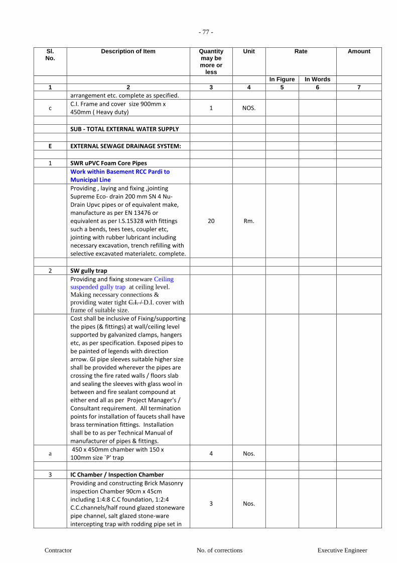
- 77 -
Contractor No. of corrections Executive Engineer
Sl. No.
Description of Item Quantity may be more or
less
Unit Rate Amount
In Figure In Words 1 2 3 4 5 6 7
arrangement etc. complete as specified.
c C.I. Frame and cover size 900mm x 450mm ( Heavy duty)
1 NOS.
SUB - TOTAL EXTERNAL WATER SUPPLY
E EXTERNAL SEWAGE DRAINAGE SYSTEM:
1 SWR uPVC Foam Core Pipes
Work within Basement RCC Pardi to Municipal Line
Providing , laying and fixing ,jointing Supreme Eco- drain 200 mm SN 4 Nu- Drain Upvc pipes or of equivalent make, manufacture as per EN 13476 or equivalent as per I.S.15328 with fittings such a bends, tees tees, coupler etc, jointing with rubber lubricant including necessary excavation, trench refilling with selective excavated materialetc. complete.
20 Rm.
2 SW gully trap
Providing and fixing stoneware Ceiling
suspended gully trap at ceiling level.
Making necessary connections &
providing water tight C.I. / D.I. cover with
frame of suitable size.
Cost shall be inclusive of Fixing/supporting the pipes (& fittings) at wall/ceiling level supported by galvanized clamps, hangers etc, as per specification. Exposed pipes to be painted of legends with direction arrow. GI pipe sleeves suitable higher size shall be provided wherever the pipes are crossing the fire rated walls / floors slab and sealing the sleeves with glass wool in between and fire sealant compound at either end all as per Project Manager's / Consultant requirement. All termination points for installation of faucets shall have brass termination fittings. Installation shall be to as per Technical Manual of manufacturer of pipes & fittings.
a 450 x 450mm chamber with 150 x 100mm size `P' trap
4 Nos.
3 IC Chamber / Inspection Chamber
Providing and constructing Brick Masonry inspection Chamber 90cm x 45cm including 1:4:8 C.C foundation, 1:2:4 C.C.channels/half round glazed stoneware pipe channel, salt glazed stone-ware intercepting trap with rodding pipe set in
3 Nos.

- 78 -
Contractor No. of corrections Executive Engineer
Sl. No.
Description of Item Quantity may be more or
less
Unit Rate Amount
In Figure In Words 1 2 3 4 5 6 7
1:4:8 cement concrete block, brick masonry plastering inside and Outside, with C.I. lead cover of 75 kg with frame fixed in cement concrete.
Contractor shall submit the structural design and drawings for the approval of Project Manager prior to execution.
4 Sewer Trap
Providing, laying, testing and commissioning of Sewer Trap in CC 1:2:4 as diverted and as specified.
a Sewer Trap (150 x 230mm ) 1 Nos.
SUB-TOTAL (EXTERNAL SEWAGE DRAINAGE SYSTEM)
F EXTERNAL STORM DRAINAGE SYSTEM:
1 SWR uPVC Foam Core Pipes
1.1 Work within Ground Floor all round drainage
Providing , laying and fixing ,jointing Supreme Eco- drain 160 mm SN 4 Nu- Drain Upvc pipes or of equivalent make, manufacture as per EN 13476 or equivalent as per I.S.15328 with fittings such a bends, tees , coupler, etc, jointing with rubber lubricant including necessary excavation, trench refilling with selective excavated materialetc. complete.
250 Rm.
1.2 Work within Basement RCC Pardi to Harvesting Tank
Providing , laying and fixing ,jointing Supreme Eco- drain 200 mm SN 4 Nu- Drain Upvc pipes or of equivalent make, manufacture as per EN 13476 or equivalent as per I.S.15328 with fittings such a bends, tees tees, coupler etc, jointing with rubber lubricant including necessary excavation, trench refilling with selective excavated materialetc. complete.
100 Rm.
2 Rain Water Chamber
Designing and constructing brick masonry inspection chamber of the following sizes
in brick work of class 75 in cement mortar
1:5 (1 cement:5 fine sand), R.C.C. at top
level with 1:2:4 mix (1 cement : 2 coarse
sand : 4 graded stone aggregate 20mm.
nominal size) embeded with frame for
manhole, RCC foundation slab. 1:2:4 mix
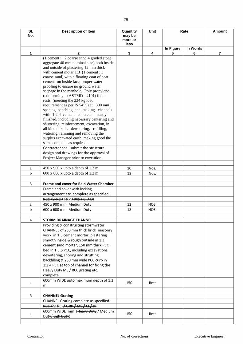
- 79 -
Contractor No. of corrections Executive Engineer
Sl. No.
Description of Item Quantity may be more or
less
Unit Rate Amount
In Figure In Words 1 2 3 4 5 6 7
(1 cement : 2 coarse sand:4 graded stone
aggregate 40 mm nominal size) both inside
and outside of plastering 12 mm thick
with cement motar 1:3 (1 cement : 3
coarse sand) with a floating coat of neat
cement on inside face, proper water
proofing to ensure no ground water
seepage in the manhole, Poly propylene
(conforming to ASTMD - 4101) foot
rests (meeting the 224 kg load
requirement as per IS 5455) at 300 mm
spacing, benching and making channels
with 1:2:4 cement concrete neatly
finished, including necessary centering and
shuttering, reinforcement, excavation, in
all kind of soil, dewatering, refilling,
watering, ramming and removing the
surplus excavated earth, making good the
same complete as required.
Contractor shall submit the structural design and drawings for the approval of Project Manager prior to execution.
a 450 x 900 x upto a depth of 1.2 m 10 Nos.
b 600 x 600 x upto a depth of 1.2 m 18 Nos.
3 Frame and cover for Rain Water Chamber
Frame and cover with locking arrangement etc. complete as specified.
RCC /SFRC / FRP / MS / CI / DI
a 450 x 900 mm, Medium Duty 12 NOS.
b 600 x 600 mm, Medium Duty 18 NOS.
4 STORM DRAINAGE CHANNEL
Providing & constructing stormwater CHANNEL of 230 mm thick brick masonry work in 1:5 cement mortar, plastering smooth inside & rough outside in 1:3 cement sand mortar, 150 mm thick PCC bed in 1:3:6 PCC, including excavations, dewatering, shoring and strutting, backfilling & 230 mm wide PCC curb in 1:2:4 PCC at top of channel for fixing the Heavy Duty MS / RCC grating etc. complete.
a 600mm WIDE upto maximum depth of 1.2 m.
150 Rmt
5 CHANNEL Grating
CHANNEL Grating complete as specified.
RCC / SFRC / GRP / MS / CI / DI
a 600mm WIDE mm (Heavy Duty / Medium Duty/ Ligh Duty)
150 Rmt
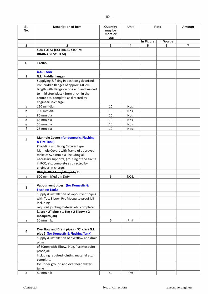
- 80 -
Contractor No. of corrections Executive Engineer
Sl. No.
Description of Item Quantity may be more or
less
Unit Rate Amount
In Figure In Words 1 2 3 4 5 6 7
SUB-TOTAL (EXTERNAL STORM DRAINAGE SYSTEM)
G TANKS
U.G. TANK
1 G.I. Puddle flanges
Supplying & fixing in position galvanised iron puddle flanges of approx. 60 cm length with flange on one end and welded to mild steel plate (8mm thick) in the centre etc. complete as directed by engineer-in-charge
a 150 mm dia 10 Nos.
b 100 mm dia 10 Nos.
c 80 mm dia 10 Nos.
d 65 mm dia 10 Nos.
e 50 mm dia 10 Nos.
f 25 mm dia 10 Nos.
2 Manhole Covers (for domestic, Flushing & Fire Tank)
Providing and fixing Circular type Manhole Covers with frame of approved make of 525 mm dia including all necessary supports, grouting of the frame in RCC, etc. complete as directed by engineer-in-charge.
RCC /SFRC / FRP / MS / CI / DI
a 600 mm, Medium Duty 6 NOS.
3 Vapour vent pipes (for Domestic & Flushing Tank)
Supply & installation of vapour vent pipes
with Tee, Elbow, Pvc Mosquito proof jali including
required jointing material etc. complete.
(1 set = 2'' pipe + 1 Tee + 2 Elbow + 2 mosquito jali)
a 50 mm n.b. 6 Rmt
4 Overflow and Drain pipes ("C" class G.I. pipe ) (for Domestic & Flushing Tank)
Supply & installation of overflow and drain pipes
of 50mm with Elbow, Plug, Pvc Mosquito proof jali
including required jointing material etc. complete.
for under ground and over head water tanks
a 80 mm n.b 50 Rmt

- 81 -
Contractor No. of corrections Executive Engineer
Sl. No.
Description of Item Quantity may be more or
less
Unit Rate Amount
In Figure In Words 1 2 3 4 5 6 7
5 Float Valve (for Domestic & Flushing Tank)
Providing and fixing in position of approved quality high pressure rated Gun Metal Float Valve with copper ball
float and brass rods of required length of
the following sizes:
Tested pressure = 15 Kg / Sqcm
Material : Gun Metal
c 80 mm n.b 2 NOS.
O.H. TANK
6 G.I. Puddle flanges
Supplying & fixing in position galvanised iron puddle flanges of approx. 60 cm length with flange on one end and welded to mild steel plate (8mm thick) in the centre etc. complete as directed by engineer-in-charge
a 150 mm dia 10 Nos.
b 100 mm dia 10 Nos.
c 80 mm dia 10 Nos.
d 65 mm dia 10 Nos.
e 50 mm dia 10 Nos.
f 25 mm dia 10 Nos.
7 Manhole Covers (for domestic, Flushing & Fire Tank)
Providing and fixing Circular type Manhole Covers with frame of approved make of 525 mm dia including all necessary supports, grouting of the frame in RCC, etc. complete as directed by engineer-in-charge.
RCC /SFRC / FRP / MS / CI / DI
b 600 mm, Medium Duty 6 NOS.
8 Vapour vent pipes (for Domestic, Flushing & Fire Tank)
Supply & installation of vapour vent pipes
with Tee, Elbow, Pvc Mosquito proof jali including
required jointing material etc. complete.
(1 set = 2'' pipe + 1 Tee + 2 Elbow + 2 mosquito jali)
a 50 mm n.b. 6 Rmt
9 Overflow and Drain pipes ("C" class G.I. pipe ) (for Domestic & Flushing Tank)
Supply & installation of overflow and drain pipes
of 50mm with Elbow, Plug, Pvc Mosquito

- 82 -
Contractor No. of corrections Executive Engineer
Sl. No.
Description of Item Quantity may be more or
less
Unit Rate Amount
In Figure In Words 1 2 3 4 5 6 7
proof jali
including required jointing material etc. complete.
for under ground and over head water tanks
a 80 mm n.b 20 Rmt
10 Butterfly Valve (OH Tank outlet & Drain)
Providing & fixing butterfly valve (Body : Grey Cast Iron, Shaft : SS, Disc : SG Iron (Rilson coated), Liner : HT - EPDM) (upto 150mm dia with hand lever operation & above with gear box operation). Including rubber gasket, flanges, nuts, bolts, washers & painting complete as required.
Tested pressure = 15 Kg / Sqcm
Material : Cast Iron
a 65 mm n.b 2 NOS.
b 80 mm n.b 2 NOS.
11 Y-Strainer (For OH Tank outlet)
Providing & fixing Y-Strainer complete as
required.
Tested pressure = 15 Kg / Sqcm
Material : Cast Iron
a 65 mm n.b 1 NOS.
b 80 mm n.b 1 NOS.
c 100 mm n.b NOS.
12 G. M. S. Ladder (From Terrace to O.H. Tank)
Providing and laying factory fabricated G. M. S. Ladder with 3 coats of zinc rich epoxy paint over a coat primer etc complete as directed.
a 4 m long x 450 mm wide 2 Nos.
SUB - TOTAL (TANKS)
H PUMPS AND EQUIPMENT
1 Water Transfer Pump for Single O.H. Tank
PUMPS: Providing, installation, testing and commissioning of totally Stainless Steel pumps having 304 SS casing, Bronze impellers, SS shaft and driven by suitable HP , 415 Volts, 50 cycles, AC 3 phase motor. Each pump should be capable of delivering as req demand, complete with all accessories, suction/discharge butterfly or gate valves, suction strainers, discharge non-return valves, pressure gauges, etc.

- 83 -
Contractor No. of corrections Executive Engineer
Sl. No.
Description of Item Quantity may be more or
less
Unit Rate Amount
In Figure In Words 1 2 3 4 5 6 7
complete and as directed.
PANELS: Providing, installation, testing and commissioning of sheet steel clad wall mounting control panel having suitably rated incoming isolating switch incoming voltmeter with selector switch and fuses. DOL starter with hand reset overload cum single-phase preventor type relay, ammeter to read current in any one phase. OFF/AUTO/MANUAL selector switch, pump changeover facility, dry run presenter switch and NHT Italian make and equivalent level switch for automatic control of pump and electronic toggle relay for automatic alternating of pumps.
Providing, installation, testing and commissioning of PVC armoured/ sheathed/insulated copper cables of the required ratings (as approved) with terminations, installation, accessories, cable trays, saddles, clamps, complete in all respects to all Plumbing Equipment from the above Power Panel located in the Pump room. Cost shall be inclusive of Supporting angle for Submersible pump.
a Domestic Water Transfer Pump
1 Set = 2 Nos. Pump (1 Working + 1 Standby)
TYPE OF PUMP = Centrifugal / or Submersible pump
Pump Capacity / Discharge = 170 lpm
outlet Head = 100 mwc 1 Sets.
b Flushing Water Transfer Pump
1 Set = 2 Nos. Pump (1 Working + 1 Standby)
TYPE OF PUMP = Centrifugal / or Submersible pump
Pump Capacity / Discharge = 250 lpm
outlet Head = 100 mwc 1 Sets.
c STP Treated Water Transfer Pump
1 Set = 2 Nos. Pump (1 Working + 1 Standby)
TYPE OF PUMP = Centrifugal / or Submersible pump
Pump Capacity / Discharge = 100 lpm
outlet Head = 100 mwc 1 Sets.
d Rain Water Transfer Pump (For Rain Water Harvesting Tank)
1 Set = 2 Nos. Pump (1 Working + 1

- 84 -
Contractor No. of corrections Executive Engineer
Sl. No.
Description of Item Quantity may be more or
less
Unit Rate Amount
In Figure In Words 1 2 3 4 5 6 7
Standby)
TYPE OF PUMP = Centrifugal / or Submersible pump
Pump Capacity / Discharge = 100 lpm
outlet Head = 100 mwc 1 Sets.
2 Sump Pump ( For BASEMENT STORM DRAINAGE SYSTEM / BASEMENT TOILET SEWAGE DRAINAGE SYSTEM )
PUMPS: Providing, installation, testing and commissioning of dewatering sewage sump pump with motor etc complete and as directed with necessary accessories and equipment (valves etc ) including the pump panel as required. complete with all accessories, suction/discharge butterfly or gate valves, suction strainers, discharge non-return valves, pressure gauges, etc. complete and as directed.
PANELS: Providing, installation, testing and commissioning of sheet steel clad wall mounting control panel having suitably rated incoming isolating switch incoming voltmeter with selector switch and fuses. DOL starter with hand reset overload cum single-phase preventor type relay, ammeter to read current in any one phase. OFF/AUTO/MANUAL selector switch, pump changeover facility, dry run presenter switch and NHT Italian make and equivalent level switch for automatic control of pump and electronic toggle relay for automatic alternating of pumps.
Providing, installation, testing and commissioning of PVC armoured/ sheathed/insulated copper cables of the required ratings (as approved) with terminations, installation, accessories, cable trays, saddles, clamps, complete in all respects to all Plumbing Equipment from the above Power Panel located in the Pump room. Cost shall be inclusive of Supporting angle for Submersible pump.
a Sump Pump ( For Car pit Drainage + 4 Plumbing Duct drainage)
(1 working + 1standby)
Pump Capacity / Discharge =50 lpm
outlet Head = 30 mwc 11 Sets.
b Sump Pump ( For Storm Water Drainage )
(1 working + 1standby)

- 85 -
Contractor No. of corrections Executive Engineer
Sl. No.
Description of Item Quantity may be more or
less
Unit Rate Amount
In Figure In Words 1 2 3 4 5 6 7
Pump Capacity / Discharge =50 lpm
outlet Head = 20 mwc 2 Sets.
c Sump Pump ( For Toilet Sewage Drainage ) Ground Floor & Basement 1
(1 working + 1standby)
Pump Capacity / Discharge =15 lpm
outlet Head = 12 mwc 3 Sets.
(NOTE: Incoming cable to the panel will be in the scope of the Electrical Contractor, but the termination of it in the panel will be in the scope of the Plumbing Contractor)
SUB-TOTAL ( PUMPS AND EQUIPMENT)
I Sewage Treatment Plant (STP)
Supply, Installation, Testing and Commissioning of Sewage Treatment Plant (STP) and complete as directed with all accessories.
a 100 KLD 1 Sets.
J Organic Waste Composer
Supply, Installation, Testing and Commissioning of Organic Waste Composer (OWC) and complete as directed with all accessories.
a 500 KG 1 Sets.
K Approval of Plumbing System From Local Authority
a
Liasoning work with Approval of Plumbing system from local authority and any other relevant statutory authority at initial & various other stages of works, including preparation of report / drawings as per fire authority. Contractor shall include cost of all liaison works which are not explicitly mentioned above but are mandatory to have local authority approval (any statutory charges will be paid exta)
1 Lumpsu
m
Official / Statutory charges
b Any Official / statutory charges will be
paid extra (Scope of M/s. Client) 1
Lumpsum
SUB - TOTAL (APPROVAL OF PLUMBING SYSTEM FROM LOCAL AUTHORITY)
A INTERNAL WATER SUPPLY SYSTEM:

- 86 -
Contractor No. of corrections Executive Engineer
Sl. No.
Description of Item Quantity may be more or
less
Unit Rate Amount
In Figure In Words 1 2 3 4 5 6 7
1 Work within Toilet/Pantry/Kitchen area Concealed piping (Water Supply Domestic)
CPVC Pipe (Chlorinated Polyvinyl Chloride)
SDR 11: Pipes to be used from 1/2 Inch to 2 Inch (7 Bar @ 82 Deg C and 28 Bar @ 23 Deg C)
Schedule 80: Pipe to be used from 2-1/2 Inch to 6 Inch.
Providing and fixing CPVC (Chlorinated
Poly Vinyl Chloride) water supply pipes .
Pipes shall be joined using solvent welded
CPVC fittings i.e. Tees, Elbows, Couplers,
Unions, Reducers, brushings etc. including
transition fittings (connection between
CPVC & metal pipe/GI) i.e. Brass
Adaptors (both Male & Female threaded)
conforming to ASTM D-2846. ASTM
F441 with only CPVC solvent cement
conforming to ASTM F-493. All
termination points for installation of
faucets shall have brass termination
fittings. Installation shall be to as per
Technical Manual of manufacturer of
pipes & fittings. Cost shall be inclusive of
insulation for hot water pipe. and also Cost
shall be inclusive of pipe length whether
Geyser installed in Shower area or in
plumbing shaft.
Cost shall be inclusive of Making maximum of 7.5 x 7.5 cm chase in wall
and floors for the pipe, making good the
same by using 1:2 cement mortar over the
wire mesh and providing protection to
embedded pipes and fittings (in wall
chase) by wrapping two layers of 400
micron polythene sheet including proper
overlaps on joints complete as required.
a 25 mm dia 260 Rmt
b 20 mm dia 1255 Rmt
c 15 mm dia 790 Rmt
2 Work within Toilet/Pantry/Kitchen area Concealed piping (Water Supply Flushing)
CPVC Pipe (Chlorinated Polyvinyl Chloride)
SDR 11: Pipes to be used from 1/2 Inch to 2 Inch (7 Bar @ 82 Deg C and 28 Bar @ 23 Deg C)
Schedule 80: Pipe to be used from 2-1/2 Inch to 6 Inch.
Providing and fixing CPVC (Chlorinated
Poly Vinyl Chloride) water supply pipes .
Pipes shall be joined using solvent welded

- 87 -
Contractor No. of corrections Executive Engineer
Sl. No.
Description of Item Quantity may be more or
less
Unit Rate Amount
In Figure In Words 1 2 3 4 5 6 7
CPVC fittings i.e. Tees, Elbows, Couplers,
Unions, Reducers, brushings etc. including
transition fittings (connection between
CPVC & metal pipe/GI) i.e. Brass
Adaptors (both Male & Female threaded)
conforming to ASTM D-2846. ASTM
F441 with only CPVC solvent cement
conforming to ASTM F-493. All
termination points for installation of
faucets shall have brass termination
fittings. Installation shall be to as per
Technical Manual of manufacturer of
pipes & fittings. Cost shall be inclusive of
insulation for hot water pipe. and also Cost
shall be inclusive of pipe length whether
Geyser installed in Shower area or in
plumbing shaft.
Cost shall be inclusive of Making maximum of 7.5 x 7.5 cm chase in wall
and floors for the pipe, making good the
same by using 1:2 cement mortar over the
wire mesh and providing protection to
embedded pipes and fittings (in wall
chase) by wrapping two layers of 400
micron polythene sheet including proper
overlaps on joints complete as required.
a 40 mm dia 1010 Rmt
b 32 mm dia 750 Rmt
3 Work within Plumbng Duct (Water Supply Domestic )
uPVC (unplasticized Polyvinyl Chloride) (SCHEDULE 40 / SCHEDULE 80)
Pipes shall be joined using solvent welded UPVC fittings i.e. Tees, Elbows, Couplers, Unions, Reducers, brushings etc. including transition fittings (connection between UPVC & metal pipe/GI) i.e. Brass Adaptors (both Male & Female threaded) conforming to ASTM D-2846. ASTM F441 with only UPVC solvent cement conforming to ASTM F-493. All termination points for installation of faucets shall have brass termination fittings. Installation shall be to as per Technical Manual of manufacturer of pipes & fittings. Including ball valve, Butterfly valve, PRV,with all fittings i.e. Tee, Elbow, flanges / union, rubber gasket, nuts, bolts, jointing material, washers & painting complete as required.
Cost shall be inclusive of Fixing/supporting the pipes (& fittings) at wall/ceiling level supported by galvanized clamps, hangers etc, as per specification. Exposed pipes to

- 88 -
Contractor No. of corrections Executive Engineer
Sl. No.
Description of Item Quantity may be more or
less
Unit Rate Amount
In Figure In Words 1 2 3 4 5 6 7
be painted of legends with direction arrow. GI pipe sleeves suitable higher size shall be provided wherever the pipes are crossing the fire rated walls / floors slab and sealing the sleeves with glass wool in between and fire sealant compound at either end all as per Project Manager's / Consultant requirement. All termination points for installation of faucets shall have brass termination fittings. Installation shall be to as per Technical Manual of manufacturer of pipes & fittings.
a 50 mm dia 48 Rmt
b 40 mm dia 96 Rmt
c 32 mm dia 102 Rmt
d 25 mm dia 376 Rmt
4 Work within Plumbng Duct (Water Supply Flushing)
uPVC (unplasticized Polyvinyl Chloride) (SCHEDULE 40 / SCHEDULE 80)
Pipes shall be joined using solvent welded UPVC fittings i.e. Tees, Elbows, Couplers, Unions, Reducers, brushings etc. including transition fittings (connection between UPVC & metal pipe/GI) i.e. Brass Adaptors (both Male & Female threaded) conforming to ASTM D-2846. ASTM F441 with only UPVC solvent cement conforming to ASTM F-493. All termination points for installation of faucets shall have brass termination fittings. Installation shall be to as per Technical Manual of manufacturer of pipes & fittings. Including ball valve, Butterfly valve, PRV,with all fittings i.e. Tee, Elbow, flanges / union, rubber gasket, nuts, bolts, jointing material, washers & painting complete as required.
Cost shall be inclusive of Fixing/supporting the pipes (& fittings) at wall/ceiling level supported by galvanized clamps, hangers etc, as per specification. Exposed pipes to be painted of legends with direction arrow. GI pipe sleeves suitable higher size shall be provided wherever the pipes are crossing the fire rated walls / floors slab and sealing the sleeves with glass wool in between and fire sealant compound at either end all as per Project Manager's / Consultant requirement. All termination points for installation of faucets shall have brass termination fittings. Installation
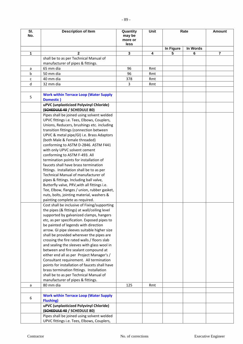
- 89 -
Contractor No. of corrections Executive Engineer
Sl. No.
Description of Item Quantity may be more or
less
Unit Rate Amount
In Figure In Words 1 2 3 4 5 6 7
shall be to as per Technical Manual of manufacturer of pipes & fittings.
a 65 mm dia 96 Rmt
b 50 mm dia 96 Rmt
c 40 mm dia 378 Rmt
d 32 mm dia 3 Rmt
5 Work within Terrace Loop (Water Supply Domestic )
uPVC (unplasticized Polyvinyl Chloride) (SCHEDULE 40 / SCHEDULE 80)
Pipes shall be joined using solvent welded UPVC fittings i.e. Tees, Elbows, Couplers, Unions, Reducers, brushings etc. including transition fittings (connection between UPVC & metal pipe/GI) i.e. Brass Adaptors (both Male & Female threaded) conforming to ASTM D-2846. ASTM F441 with only UPVC solvent cement conforming to ASTM F-493. All termination points for installation of faucets shall have brass termination fittings. Installation shall be to as per Technical Manual of manufacturer of pipes & fittings. Including ball valve, Butterfly valve, PRV,with all fittings i.e. Tee, Elbow, flanges / union, rubber gasket, nuts, bolts, jointing material, washers & painting complete as required.
Cost shall be inclusive of Fixing/supporting the pipes (& fittings) at wall/ceiling level supported by galvanized clamps, hangers etc, as per specification. Exposed pipes to be painted of legends with direction arrow. GI pipe sleeves suitable higher size shall be provided wherever the pipes are crossing the fire rated walls / floors slab and sealing the sleeves with glass wool in between and fire sealant compound at either end all as per Project Manager's / Consultant requirement. All termination points for installation of faucets shall have brass termination fittings. Installation shall be to as per Technical Manual of manufacturer of pipes & fittings.
a 80 mm dia 125 Rmt
6 Work within Terrace Loop (Water Supply Flushing)
uPVC (unplasticized Polyvinyl Chloride) (SCHEDULE 40 / SCHEDULE 80)
Pipes shall be joined using solvent welded UPVC fittings i.e. Tees, Elbows, Couplers,

- 90 -
Contractor No. of corrections Executive Engineer
Sl. No.
Description of Item Quantity may be more or
less
Unit Rate Amount
In Figure In Words 1 2 3 4 5 6 7
Unions, Reducers, brushings etc. including transition fittings (connection between UPVC & metal pipe/GI) i.e. Brass Adaptors (both Male & Female threaded) conforming to ASTM D-2846. ASTM F441 with only UPVC solvent cement conforming to ASTM F-493. All termination points for installation of faucets shall have brass termination fittings. Installation shall be to as per Technical Manual of manufacturer of pipes & fittings. Including ball valve, Butterfly valve, PRV,with all fittings i.e. Tee, Elbow, flanges / union, rubber gasket, nuts, bolts, jointing material, washers & painting complete as required.
Cost shall be inclusive of Fixing/supporting the pipes (& fittings) at wall/ceiling level supported by galvanized clamps, hangers etc, as per specification. Exposed pipes to be painted of legends with direction arrow. GI pipe sleeves suitable higher size shall be provided wherever the pipes are crossing the fire rated walls / floors slab and sealing the sleeves with glass wool in between and fire sealant compound at either end all as per Project Manager's / Consultant requirement. All termination points for installation of faucets shall have brass termination fittings. Installation shall be to as per Technical Manual of manufacturer of pipes & fittings.
a 80 mm dia 125 Rmt
7 VALVES in Terrace & Plumbing Duct (For Domestic and Flushing)
7.1 Ball Valve
Providing and fixing ball valve including
flanges / union, etc. complete as required.
Tested pressure = 15 Kg / Sqcm
Material : Brass
a 20 mm n.b 4 NOS.
b 25 mm n.b 45 NOS.
c 32 mm n.b 4 NOS.
d 40 mm n.b 45 NOS.
e 50 mm n.b 4 NOS.
7.2 Butterfly Valve (Terrace Floor)
Providing & fixing butterfly valve (Body : Grey Cast Iron, Shaft : SS, Disc : SG Iron (Rilson coated), Liner : HT - EPDM) (upto 150mm dia with hand lever operation & above with gear box operation). Including

- 91 -
Contractor No. of corrections Executive Engineer
Sl. No.
Description of Item Quantity may be more or
less
Unit Rate Amount
In Figure In Words 1 2 3 4 5 6 7
rubber gasket, flanges, nuts, bolts, washers & painting complete as required.
Tested pressure = 15 Kg / Sqcm
Material : Cast Iron
a 65 mm n.b 4 NOS.
7.3 Air Vent valve (Terrace Floor PIPE LOOP)
Providing & fixing Auto Air vent for cold
water supply risers.
Tested pressure = 15 Kg / Sqcm
Material : Cast Iron
a 15 mm n.b 8 NOS.
7.4 P.R.V.
Providing and fixing Pressure Reducing valves complete as directed by engineer-in-charge. Contractor to set pressure as per instructions from consultant during execution.
Note: Set of P.R.V. of including 5 nos. x Ball / Butterfly Valve + 2 nos. x P.R.V.
Tested pressure = 25 Kg / Sqcm
Material : Forged Brass / Bronze
a 40 mm n.b 5 NOS.
b 50 mm n.b 3 NOS.
c 65 mm n.b 6 NOS.
SUB-TOTAL (Internal Water Supply System)
B INTERNAL SEWAGE DRAINAGE SYSTEM:
Work with in TOILET / Kitchen
1 UPVC Floor traps (plain / multi)
Supply, Installation, Testing and Commissioning
of upvc Floor traps (plain / multi) of self cleansing design
with water seal not less than 25mm
with or without vent, including setting the trap
in cement concrete M-15 as per specifications etc. complete.
Rate to include making of opening in floor, marble / tiles, for fixing
1.1 Floor traps (for Toilet / Kitchen)
a Trap with 110mm inlet & 75mm outlet. 150 NOS.
1.2 Multifloor traps (for Toilet / Kitchen)
a Trap with 110mm inlet & 75mm outlet. 200 NOS.
2 SWR PVC pipes (Type-B) (For Pipes in
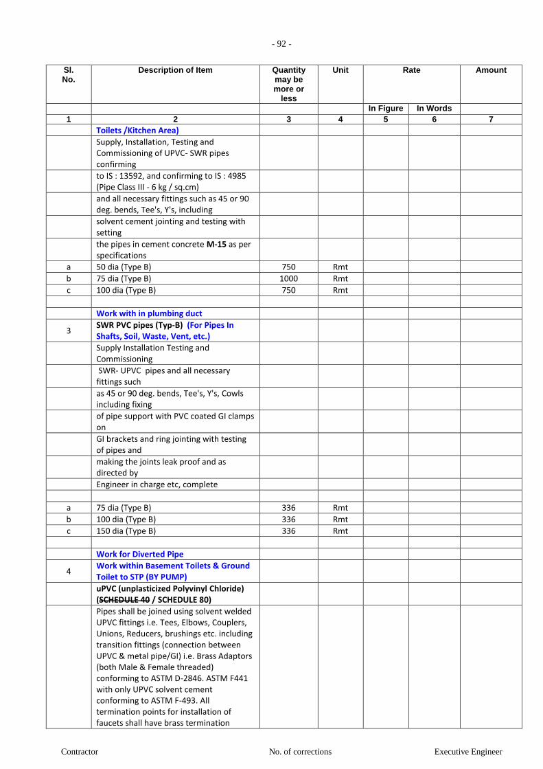
- 92 -
Contractor No. of corrections Executive Engineer
Sl. No.
Description of Item Quantity may be more or
less
Unit Rate Amount
In Figure In Words 1 2 3 4 5 6 7
Toilets /Kitchen Area)
Supply, Installation, Testing and Commissioning of UPVC- SWR pipes confirming
to IS : 13592, and confirming to IS : 4985 (Pipe Class III - 6 kg / sq.cm)
and all necessary fittings such as 45 or 90 deg. bends, Tee's, Y's, including
solvent cement jointing and testing with setting
the pipes in cement concrete M-15 as per specifications
a 50 dia (Type B) 750 Rmt
b 75 dia (Type B) 1000 Rmt
c 100 dia (Type B) 750 Rmt
Work with in plumbing duct
3 SWR PVC pipes (Typ-B) (For Pipes In Shafts, Soil, Waste, Vent, etc.)
Supply Installation Testing and Commissioning
SWR- UPVC pipes and all necessary fittings such
as 45 or 90 deg. bends, Tee's, Y's, Cowls including fixing
of pipe support with PVC coated GI clamps on
GI brackets and ring jointing with testing of pipes and
making the joints leak proof and as directed by
Engineer in charge etc, complete
a 75 dia (Type B) 336 Rmt
b 100 dia (Type B) 336 Rmt
c 150 dia (Type B) 336 Rmt
Work for Diverted Pipe
4 Work within Basement Toilets & Ground Toilet to STP (BY PUMP)
uPVC (unplasticized Polyvinyl Chloride) (SCHEDULE 40 / SCHEDULE 80)
Pipes shall be joined using solvent welded UPVC fittings i.e. Tees, Elbows, Couplers, Unions, Reducers, brushings etc. including transition fittings (connection between UPVC & metal pipe/GI) i.e. Brass Adaptors (both Male & Female threaded) conforming to ASTM D-2846. ASTM F441 with only UPVC solvent cement conforming to ASTM F-493. All termination points for installation of faucets shall have brass termination

- 93 -
Contractor No. of corrections Executive Engineer
Sl. No.
Description of Item Quantity may be more or
less
Unit Rate Amount
In Figure In Words 1 2 3 4 5 6 7
fittings. Installation shall be to as per Technical Manual of manufacturer of pipes & fittings. Including ball valve, Butterfly valve, PRV,with all fittings i.e. Tee, Elbow, flanges / union, rubber gasket, nuts, bolts, jointing material, washers & painting complete as required.
Cost shall be inclusive of Fixing/supporting the pipes (& fittings) at wall/ceiling level supported by galvanized clamps, hangers etc, as per specification. Exposed pipes to be painted of legends with direction arrow. GI pipe sleeves suitable higher size shall be provided wherever the pipes are crossing the fire rated walls / floors slab and sealing the sleeves with glass wool in between and fire sealant compound at either end all as per Project Manager's / Consultant requirement. All termination points for installation of faucets shall have brass termination fittings. Installation shall be to as per Technical Manual of manufacturer of pipes & fittings.
c 65 mm dia 110 Rmt
5 C.I. pipes
Supply Installation Testing and Commissioning
"LA" class C.I. tested heavy pipe including fitting
indoor with heavy clamps and M S hot dip galvanized brackets
or in MS trenche on clamp.
Work within Ground ceiling shaft to STP & Work within STP to Municipal line (in case of STP nor worked)
a 160 dia 110 Rmt
SUB-TOTAL (Internal Sewage Drainage System)
C INTERNAL STORM DRAINAGE SYSTEM:
1 UPVC Floor traps
Supply, Installation, Testing and Commissioning
of upvc Floor traps of self cleansing design
with water seal not less than 25mm
with or without vent, including setting the trap
in cement concrete M-15 as per
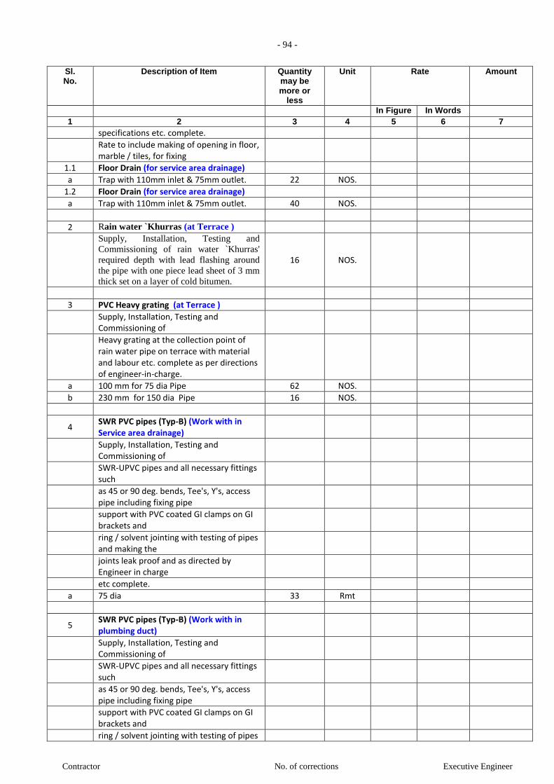
- 94 -
Contractor No. of corrections Executive Engineer
Sl. No.
Description of Item Quantity may be more or
less
Unit Rate Amount
In Figure In Words 1 2 3 4 5 6 7
specifications etc. complete.
Rate to include making of opening in floor, marble / tiles, for fixing
1.1 Floor Drain (for service area drainage)
a Trap with 110mm inlet & 75mm outlet. 22 NOS.
1.2 Floor Drain (for service area drainage)
a Trap with 110mm inlet & 75mm outlet. 40 NOS.
2 Rain water `Khurras (at Terrace )
Supply, Installation, Testing and
Commissioning of rain water `Khurras'
required depth with lead flashing around
the pipe with one piece lead sheet of 3 mm
thick set on a layer of cold bitumen.
16 NOS.
3 PVC Heavy grating (at Terrace )
Supply, Installation, Testing and Commissioning of
Heavy grating at the collection point of rain water pipe on terrace with material and labour etc. complete as per directions of engineer-in-charge.
a 100 mm for 75 dia Pipe 62 NOS.
b 230 mm for 150 dia Pipe 16 NOS.
4 SWR PVC pipes (Typ-B) (Work with in Service area drainage)
Supply, Installation, Testing and Commissioning of
SWR-UPVC pipes and all necessary fittings such
as 45 or 90 deg. bends, Tee's, Y's, access pipe including fixing pipe
support with PVC coated GI clamps on GI brackets and
ring / solvent jointing with testing of pipes and making the
joints leak proof and as directed by Engineer in charge
etc complete.
a 75 dia 33 Rmt
5 SWR PVC pipes (Typ-B) (Work with in plumbing duct)
Supply, Installation, Testing and Commissioning of
SWR-UPVC pipes and all necessary fittings such
as 45 or 90 deg. bends, Tee's, Y's, access pipe including fixing pipe
support with PVC coated GI clamps on GI brackets and
ring / solvent jointing with testing of pipes
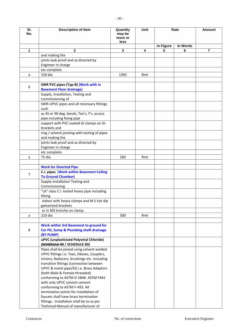
- 95 -
Contractor No. of corrections Executive Engineer
Sl. No.
Description of Item Quantity may be more or
less
Unit Rate Amount
In Figure In Words 1 2 3 4 5 6 7
and making the
joints leak proof and as directed by Engineer in charge
etc complete.
a 150 dia 1392 Rmt
6 SWR PVC pipes (Typ-B) (Work with in Basement Floor drainage)
Supply, Installation, Testing and Commissioning of
SWR-UPVC pipes and all necessary fittings such
as 45 or 90 deg. bends, Tee's, Y's, access pipe including fixing pipe
support with PVC coated GI clamps on GI brackets and
ring / solvent jointing with testing of pipes and making the
joints leak proof and as directed by Engineer in charge
etc complete.
a 75 dia 260 Rmt
Work for Diverted Pipe
7 C.I. pipes (Work within Basement Ceiling To Ground Chamber)
Supply Installation Testing and Commissioning
"LA" class C.I. tested heavy pipe including fitting
indoor with heavy clamps and M S hot dip galvanized brackets
or in MS trenche on clamp.
a 210 dia 300 Rmt
8 Work within 3rd Basement to ground for Car Pit, Sump & Plumbing shaft drainage (BY PUMP)
uPVC (unplasticized Polyvinyl Chloride) (SCHEDULE 40 / SCHEDULE 80)
Pipes shall be joined using solvent welded UPVC fittings i.e. Tees, Elbows, Couplers, Unions, Reducers, brushings etc. including transition fittings (connection between UPVC & metal pipe/GI) i.e. Brass Adaptors (both Male & Female threaded) conforming to ASTM D-2846. ASTM F441 with only UPVC solvent cement conforming to ASTM F-493. All termination points for installation of faucets shall have brass termination fittings. Installation shall be to as per Technical Manual of manufacturer of
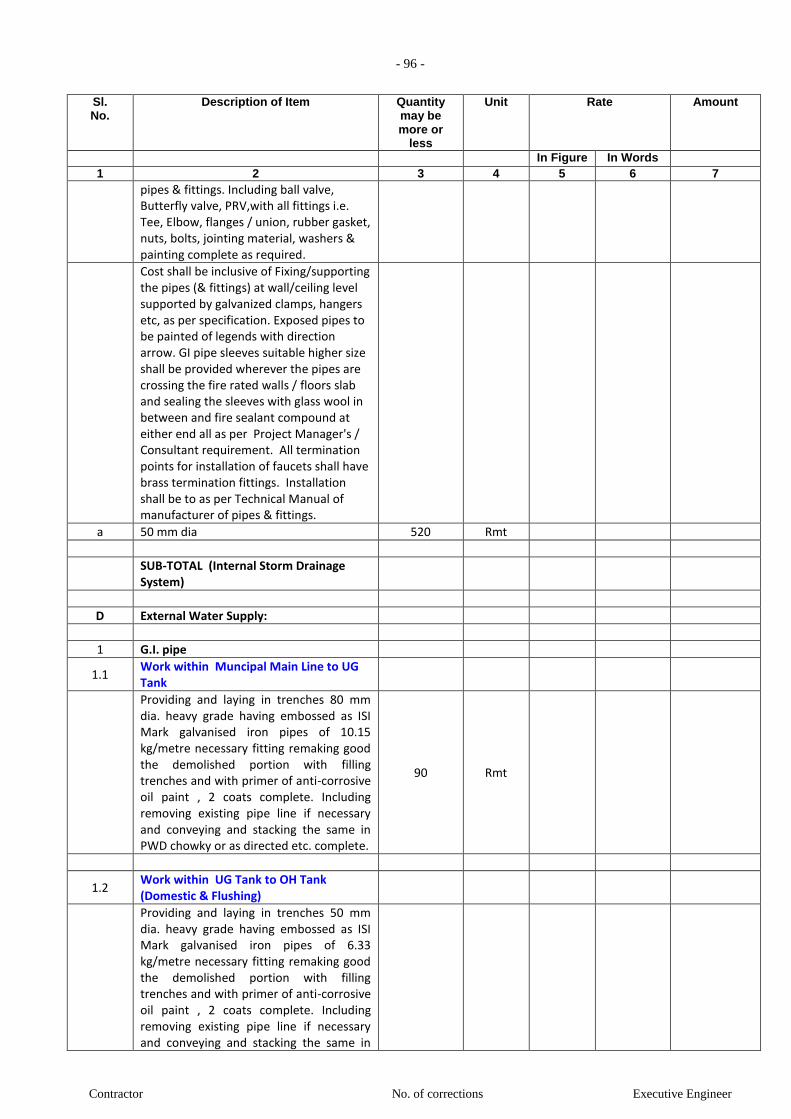
- 96 -
Contractor No. of corrections Executive Engineer
Sl. No.
Description of Item Quantity may be more or
less
Unit Rate Amount
In Figure In Words 1 2 3 4 5 6 7
pipes & fittings. Including ball valve, Butterfly valve, PRV,with all fittings i.e. Tee, Elbow, flanges / union, rubber gasket, nuts, bolts, jointing material, washers & painting complete as required.
Cost shall be inclusive of Fixing/supporting the pipes (& fittings) at wall/ceiling level supported by galvanized clamps, hangers etc, as per specification. Exposed pipes to be painted of legends with direction arrow. GI pipe sleeves suitable higher size shall be provided wherever the pipes are crossing the fire rated walls / floors slab and sealing the sleeves with glass wool in between and fire sealant compound at either end all as per Project Manager's / Consultant requirement. All termination points for installation of faucets shall have brass termination fittings. Installation shall be to as per Technical Manual of manufacturer of pipes & fittings.
a 50 mm dia 520 Rmt
SUB-TOTAL (Internal Storm Drainage System)
D External Water Supply:
1 G.I. pipe
1.1 Work within Muncipal Main Line to UG Tank
Providing and laying in trenches 80 mm dia. heavy grade having embossed as ISI Mark galvanised iron pipes of 10.15 kg/metre necessary fitting remaking good the demolished portion with filling trenches and with primer of anti-corrosive oil paint , 2 coats complete. Including removing existing pipe line if necessary and conveying and stacking the same in PWD chowky or as directed etc. complete.
90 Rmt
1.2 Work within UG Tank to OH Tank (Domestic & Flushing)
Providing and laying in trenches 50 mm dia. heavy grade having embossed as ISI Mark galvanised iron pipes of 6.33 kg/metre necessary fitting remaking good the demolished portion with filling trenches and with primer of anti-corrosive oil paint , 2 coats complete. Including removing existing pipe line if necessary and conveying and stacking the same in

- 97 -
Contractor No. of corrections Executive Engineer
Sl. No.
Description of Item Quantity may be more or
less
Unit Rate Amount
In Figure In Words 1 2 3 4 5 6 7
PWD chowky or as directed etc. complete.
a 2nd Basement 100 Rmt
b 1st Basement 12 Rmt
c Ground Floor 12 Rmt
d 1st Floor (1% charges) 12 Rmt
e 2nd Floor (2% charges) 12 Rmt
f 3rd Floor (3% charges) 12 Rmt
g 4th Floor (4% charges) 12 Rmt
h 5th Floor (5% charges) 12 Rmt
i 6th Floor (6% charges) 12 Rmt
j 7th Floor (6.5% charges) 12 Rmt
k 8th Floor (7% charges) 12 Rmt
l 9th Floor (7.5% charges) 12 Rmt
m 10th Floor (8% charges) 12 Rmt
n 11th Floor (8.5% charges) 12 Rmt
o 12th Floor (9% charges) 12 Rmt
p Terrace Floor (9.5%Charges) 40 Rmt
2 Water Meter
a
Providing and fixing 80mm diameter water meter with non-return valve including strainer, sockets/ union nut and including water meter box making locking arrangement and lock. [Without chamber].
1 NOS.
3 Water Meter chamber
a
Brick masonry chamber with 230 thick walls in C.M. 1:5, resting on 150 thick C.C. M 15 bed, 12 thick cement plaster inside and outside in C.M. 1:3. Cost shall be inclusive of excavation in all kind of soil, dewatering, backfilling, ramming & removing the surplus excavated material and making good the same complete as required and satisfaction of the Project Manager.
1 NOS.
4 Frame and cover for Water Meter chamber
Frame and cover with locking arrangement etc. complete as specified.
c C.I. Frame and cover size 900mm x 450mm ( Heavy duty)
1 NOS.
SUB - TOTAL EXTERNAL WATER SUPPLY
E EXTERNAL SEWAGE DRAINAGE SYSTEM:
1 SWR uPVC Foam Core Pipes
Work within Basement RCC Pardi to Municipal Line

- 98 -
Contractor No. of corrections Executive Engineer
Sl. No.
Description of Item Quantity may be more or
less
Unit Rate Amount
In Figure In Words 1 2 3 4 5 6 7
Providing , laying and fixing ,jointing Supreme Eco- drain 200 mm SN 4 Nu- Drain Upvc pipes or of equivalent make, manufacture as per EN 13476 or equivalent as per I.S.15328 with fittings such a bends, tees tees, coupler etc, jointing with rubber lubricant including necessary excavation, trench refilling with selective excavated materialetc. complete.
20 Rm.
2 SW gully trap
Providing and fixing stoneware Ceiling
suspended gully trap at ceiling level.
Making necessary connections &
providing water tight C.I. / D.I. cover with
frame of suitable size.
Cost shall be inclusive of Fixing/supporting the pipes (& fittings) at wall/ceiling level supported by galvanized clamps, hangers etc, as per specification. Exposed pipes to be painted of legends with direction arrow. GI pipe sleeves suitable higher size shall be provided wherever the pipes are crossing the fire rated walls / floors slab and sealing the sleeves with glass wool in between and fire sealant compound at either end all as per Project Manager's / Consultant requirement. All termination points for installation of faucets shall have brass termination fittings. Installation shall be to as per Technical Manual of manufacturer of pipes & fittings.
a 450 x 450mm chamber with 150 x 100mm size `P' trap
4 Nos.
3 IC Chamber / Inspection Chamber
Providing and constructing Brick Masonry inspection Chamber 90cm x 45cm including 1:4:8 C.C foundation, 1:2:4 C.C.channels/half round glazed stoneware pipe channel, salt glazed stone-ware intercepting trap with rodding pipe set in 1:4:8 cement concrete block, brick masonry plastering inside and Outside, with C.I. lead cover of 75 kg with frame fixed in cement concrete.
3 Nos.
Contractor shall submit the structural design and drawings for the approval of Project Manager prior to execution.
4 Sewer Trap
Providing, laying, testing and commissioning of Sewer Trap in CC 1:2:4
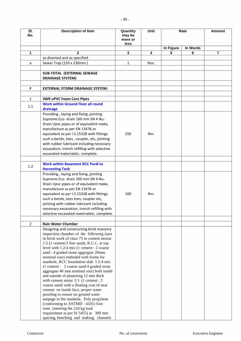
- 99 -
Contractor No. of corrections Executive Engineer
Sl. No.
Description of Item Quantity may be more or
less
Unit Rate Amount
In Figure In Words 1 2 3 4 5 6 7
as diverted and as specified.
a Sewer Trap (150 x 230mm ) 1 Nos.
SUB-TOTAL (EXTERNAL SEWAGE DRAINAGE SYSTEM)
F EXTERNAL STORM DRAINAGE SYSTEM:
1 SWR uPVC Foam Core Pipes
1.1 Work within Ground Floor all round drainage
Providing , laying and fixing ,jointing Supreme Eco- drain 160 mm SN 4 Nu- Drain Upvc pipes or of equivalent make, manufacture as per EN 13476 or equivalent as per I.S.15328 with fittings such a bends, tees , coupler, etc, jointing with rubber lubricant including necessary excavation, trench refilling with selective excavated materialetc. complete.
250 Rm.
1.2 Work within Basement RCC Pardi to Harvesting Tank
Providing , laying and fixing ,jointing Supreme Eco- drain 200 mm SN 4 Nu- Drain Upvc pipes or of equivalent make, manufacture as per EN 13476 or equivalent as per I.S.15328 with fittings such a bends, tees tees, coupler etc, jointing with rubber lubricant including necessary excavation, trench refilling with selective excavated materialetc. complete.
100 Rm.
2 Rain Water Chamber
Designing and constructing brick masonry inspection chamber of the following sizes
in brick work of class 75 in cement mortar
1:5 (1 cement:5 fine sand), R.C.C. at top
level with 1:2:4 mix (1 cement : 2 coarse
sand : 4 graded stone aggregate 20mm.
nominal size) embeded with frame for
manhole, RCC foundation slab. 1:2:4 mix
(1 cement : 2 coarse sand:4 graded stone
aggregate 40 mm nominal size) both inside
and outside of plastering 12 mm thick
with cement motar 1:3 (1 cement : 3
coarse sand) with a floating coat of neat
cement on inside face, proper water
proofing to ensure no ground water
seepage in the manhole, Poly propylene
(conforming to ASTMD - 4101) foot
rests (meeting the 224 kg load
requirement as per IS 5455) at 300 mm
spacing, benching and making channels

- 100 -
Contractor No. of corrections Executive Engineer
Sl. No.
Description of Item Quantity may be more or
less
Unit Rate Amount
In Figure In Words 1 2 3 4 5 6 7
with 1:2:4 cement concrete neatly
finished, including necessary centering and
shuttering, reinforcement, excavation, in
all kind of soil, dewatering, refilling,
watering, ramming and removing the
surplus excavated earth, making good the
same complete as required.
Contractor shall submit the structural design and drawings for the approval of Project Manager prior to execution.
a 450 x 900 x upto a depth of 1.2 m 10 Nos.
b 600 x 600 x upto a depth of 1.2 m 18 Nos.
3 Frame and cover for Rain Water Chamber
Frame and cover with locking arrangement etc. complete as specified.
RCC /SFRC / FRP / MS / CI / DI
a 450 x 900 mm, Medium Duty 12 NOS.
b 600 x 600 mm, Medium Duty 18 NOS.
4 STORM DRAINAGE CHANNEL
Providing & constructing stormwater CHANNEL of 230 mm thick brick masonry work in 1:5 cement mortar, plastering smooth inside & rough outside in 1:3 cement sand mortar, 150 mm thick PCC bed in 1:3:6 PCC, including excavations, dewatering, shoring and strutting, backfilling & 230 mm wide PCC curb in 1:2:4 PCC at top of channel for fixing the Heavy Duty MS / RCC grating etc. complete.
a 600mm WIDE upto maximum depth of 1.2 m.
150 Rmt
5 CHANNEL Grating
CHANNEL Grating complete as specified.
RCC / SFRC / GRP / MS / CI / DI
a 600mm WIDE mm (Heavy Duty / Medium Duty/ Ligh Duty)
150 Rmt
SUB-TOTAL (EXTERNAL STORM DRAINAGE SYSTEM)
G TANKS
U.G. TANK
1 G.I. Puddle flanges
Supplying & fixing in position galvanised iron puddle flanges of approx. 60 cm length with flange on one end and welded to mild steel plate (8mm thick) in the
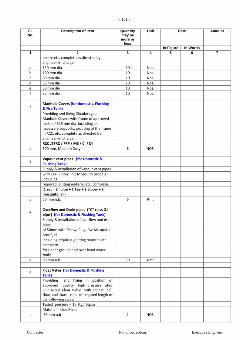
- 101 -
Contractor No. of corrections Executive Engineer
Sl. No.
Description of Item Quantity may be more or
less
Unit Rate Amount
In Figure In Words 1 2 3 4 5 6 7
centre etc. complete as directed by engineer-in-charge
a 150 mm dia 10 Nos.
b 100 mm dia 10 Nos.
c 80 mm dia 10 Nos.
d 65 mm dia 10 Nos.
e 50 mm dia 10 Nos.
f 25 mm dia 10 Nos.
2 Manhole Covers (for domestic, Flushing & Fire Tank)
Providing and fixing Circular type Manhole Covers with frame of approved make of 525 mm dia including all necessary supports, grouting of the frame in RCC, etc. complete as directed by engineer-in-charge.
RCC /SFRC / FRP / MS / CI / DI
a 600 mm, Medium Duty 6 NOS.
3 Vapour vent pipes (for Domestic & Flushing Tank)
Supply & installation of vapour vent pipes
with Tee, Elbow, Pvc Mosquito proof jali including
required jointing material etc. complete.
(1 set = 2'' pipe + 1 Tee + 2 Elbow + 2 mosquito jali)
a 50 mm n.b. 6 Rmt
4 Overflow and Drain pipes ("C" class G.I. pipe ) (for Domestic & Flushing Tank)
Supply & installation of overflow and drain pipes
of 50mm with Elbow, Plug, Pvc Mosquito proof jali
including required jointing material etc. complete.
for under ground and over head water tanks
a 80 mm n.b 50 Rmt
5 Float Valve (for Domestic & Flushing Tank)
Providing and fixing in position of approved quality high pressure rated Gun Metal Float Valve with copper ball
float and brass rods of required length of
the following sizes:
Tested pressure = 15 Kg / Sqcm
Material : Gun Metal
c 80 mm n.b 2 NOS.

- 102 -
Contractor No. of corrections Executive Engineer
Sl. No.
Description of Item Quantity may be more or
less
Unit Rate Amount
In Figure In Words 1 2 3 4 5 6 7
O.H. TANK
6 G.I. Puddle flanges
Supplying & fixing in position galvanised iron puddle flanges of approx. 60 cm length with flange on one end and welded to mild steel plate (8mm thick) in the centre etc. complete as directed by engineer-in-charge
a 150 mm dia 10 Nos.
b 100 mm dia 10 Nos.
c 80 mm dia 10 Nos.
d 65 mm dia 10 Nos.
e 50 mm dia 10 Nos.
f 25 mm dia 10 Nos.
7 Manhole Covers (for domestic, Flushing & Fire Tank)
Providing and fixing Circular type Manhole Covers with frame of approved make of 525 mm dia including all necessary supports, grouting of the frame in RCC, etc. complete as directed by engineer-in-charge.
RCC /SFRC / FRP / MS / CI / DI
b 600 mm, Medium Duty 6 NOS.
8 Vapour vent pipes (for Domestic, Flushing & Fire Tank)
Supply & installation of vapour vent pipes
with Tee, Elbow, Pvc Mosquito proof jali including
required jointing material etc. complete.
(1 set = 2'' pipe + 1 Tee + 2 Elbow + 2 mosquito jali)
a 50 mm n.b. 6 Rmt
9 Overflow and Drain pipes ("C" class G.I. pipe ) (for Domestic & Flushing Tank)
Supply & installation of overflow and drain pipes
of 50mm with Elbow, Plug, Pvc Mosquito proof jali
including required jointing material etc. complete.
for under ground and over head water tanks
a 80 mm n.b 20 Rmt
10 Butterfly Valve (OH Tank outlet & Drain)
Providing & fixing butterfly valve (Body : Grey Cast Iron, Shaft : SS, Disc : SG Iron (Rilson coated), Liner : HT - EPDM) (upto
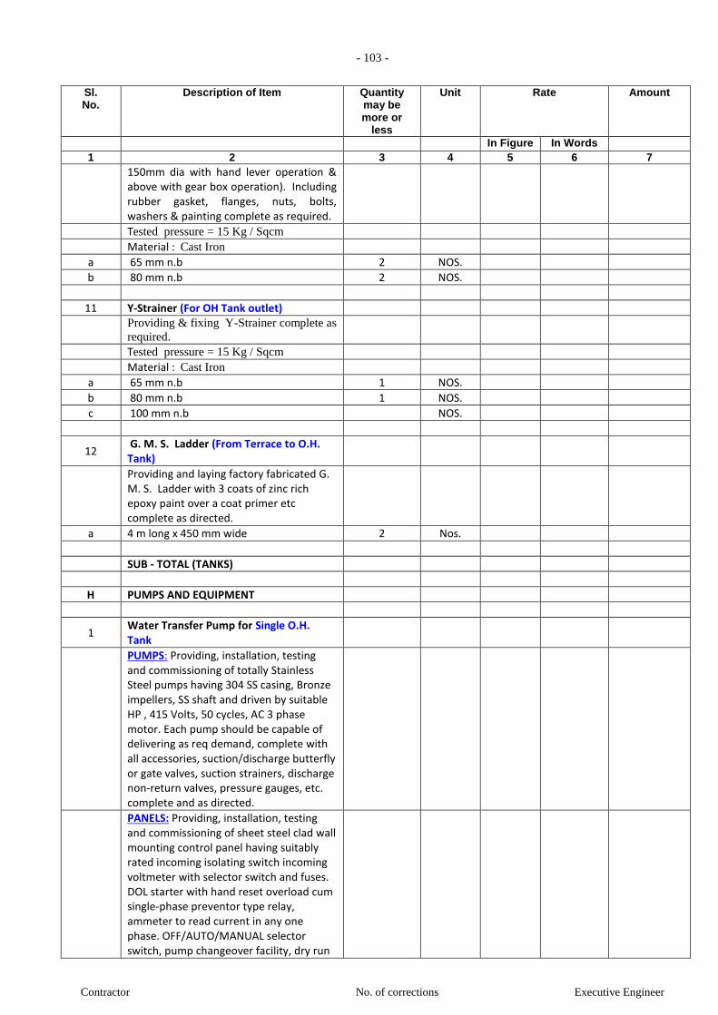
- 103 -
Contractor No. of corrections Executive Engineer
Sl. No.
Description of Item Quantity may be more or
less
Unit Rate Amount
In Figure In Words 1 2 3 4 5 6 7
150mm dia with hand lever operation & above with gear box operation). Including rubber gasket, flanges, nuts, bolts, washers & painting complete as required.
Tested pressure = 15 Kg / Sqcm
Material : Cast Iron
a 65 mm n.b 2 NOS.
b 80 mm n.b 2 NOS.
11 Y-Strainer (For OH Tank outlet)
Providing & fixing Y-Strainer complete as
required.
Tested pressure = 15 Kg / Sqcm
Material : Cast Iron
a 65 mm n.b 1 NOS.
b 80 mm n.b 1 NOS.
c 100 mm n.b NOS.
12 G. M. S. Ladder (From Terrace to O.H. Tank)
Providing and laying factory fabricated G. M. S. Ladder with 3 coats of zinc rich epoxy paint over a coat primer etc complete as directed.
a 4 m long x 450 mm wide 2 Nos.
SUB - TOTAL (TANKS)
H PUMPS AND EQUIPMENT
1 Water Transfer Pump for Single O.H. Tank
PUMPS: Providing, installation, testing and commissioning of totally Stainless Steel pumps having 304 SS casing, Bronze impellers, SS shaft and driven by suitable HP , 415 Volts, 50 cycles, AC 3 phase motor. Each pump should be capable of delivering as req demand, complete with all accessories, suction/discharge butterfly or gate valves, suction strainers, discharge non-return valves, pressure gauges, etc. complete and as directed.
PANELS: Providing, installation, testing and commissioning of sheet steel clad wall mounting control panel having suitably rated incoming isolating switch incoming voltmeter with selector switch and fuses. DOL starter with hand reset overload cum single-phase preventor type relay, ammeter to read current in any one phase. OFF/AUTO/MANUAL selector switch, pump changeover facility, dry run
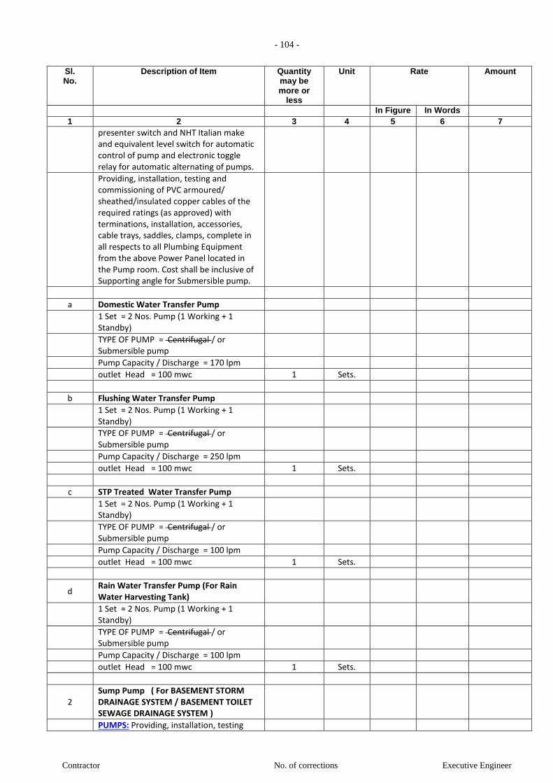
- 104 -
Contractor No. of corrections Executive Engineer
Sl. No.
Description of Item Quantity may be more or
less
Unit Rate Amount
In Figure In Words 1 2 3 4 5 6 7
presenter switch and NHT Italian make and equivalent level switch for automatic control of pump and electronic toggle relay for automatic alternating of pumps.
Providing, installation, testing and commissioning of PVC armoured/ sheathed/insulated copper cables of the required ratings (as approved) with terminations, installation, accessories, cable trays, saddles, clamps, complete in all respects to all Plumbing Equipment from the above Power Panel located in the Pump room. Cost shall be inclusive of Supporting angle for Submersible pump.
a Domestic Water Transfer Pump
1 Set = 2 Nos. Pump (1 Working + 1 Standby)
TYPE OF PUMP = Centrifugal / or Submersible pump
Pump Capacity / Discharge = 170 lpm
outlet Head = 100 mwc 1 Sets.
b Flushing Water Transfer Pump
1 Set = 2 Nos. Pump (1 Working + 1 Standby)
TYPE OF PUMP = Centrifugal / or Submersible pump
Pump Capacity / Discharge = 250 lpm
outlet Head = 100 mwc 1 Sets.
c STP Treated Water Transfer Pump
1 Set = 2 Nos. Pump (1 Working + 1 Standby)
TYPE OF PUMP = Centrifugal / or Submersible pump
Pump Capacity / Discharge = 100 lpm
outlet Head = 100 mwc 1 Sets.
d Rain Water Transfer Pump (For Rain Water Harvesting Tank)
1 Set = 2 Nos. Pump (1 Working + 1 Standby)
TYPE OF PUMP = Centrifugal / or Submersible pump
Pump Capacity / Discharge = 100 lpm
outlet Head = 100 mwc 1 Sets.
2 Sump Pump ( For BASEMENT STORM DRAINAGE SYSTEM / BASEMENT TOILET SEWAGE DRAINAGE SYSTEM )
PUMPS: Providing, installation, testing

- 105 -
Contractor No. of corrections Executive Engineer
Sl. No.
Description of Item Quantity may be more or
less
Unit Rate Amount
In Figure In Words 1 2 3 4 5 6 7
and commissioning of dewatering sewage sump pump with motor etc complete and as directed with necessary accessories and equipment (valves etc ) including the pump panel as required. complete with all accessories, suction/discharge butterfly or gate valves, suction strainers, discharge non-return valves, pressure gauges, etc. complete and as directed.
PANELS: Providing, installation, testing and commissioning of sheet steel clad wall mounting control panel having suitably rated incoming isolating switch incoming voltmeter with selector switch and fuses. DOL starter with hand reset overload cum single-phase preventor type relay, ammeter to read current in any one phase. OFF/AUTO/MANUAL selector switch, pump changeover facility, dry run presenter switch and NHT Italian make and equivalent level switch for automatic control of pump and electronic toggle relay for automatic alternating of pumps.
Providing, installation, testing and commissioning of PVC armoured/ sheathed/insulated copper cables of the required ratings (as approved) with terminations, installation, accessories, cable trays, saddles, clamps, complete in all respects to all Plumbing Equipment from the above Power Panel located in the Pump room. Cost shall be inclusive of Supporting angle for Submersible pump.
a Sump Pump ( For Car pit Drainage + 4 Plumbing Duct drainage)
(1 working + 1standby)
Pump Capacity / Discharge =50 lpm
outlet Head = 30 mwc 11 Sets.
b Sump Pump ( For Storm Water Drainage )
(1 working + 1standby)
Pump Capacity / Discharge =50 lpm
outlet Head = 20 mwc 2 Sets.
c Sump Pump ( For Toilet Sewage Drainage ) Ground Floor & Basement 1
(1 working + 1standby)
Pump Capacity / Discharge =15 lpm
outlet Head = 12 mwc 3 Sets.
(NOTE: Incoming cable to the panel will be
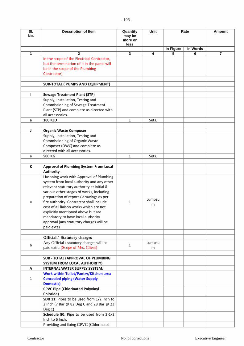
- 106 -
Contractor No. of corrections Executive Engineer
Sl. No.
Description of Item Quantity may be more or
less
Unit Rate Amount
In Figure In Words 1 2 3 4 5 6 7
in the scope of the Electrical Contractor, but the termination of it in the panel will be in the scope of the Plumbing Contractor)
SUB-TOTAL ( PUMPS AND EQUIPMENT)
I Sewage Treatment Plant (STP)
Supply, Installation, Testing and Commissioning of Sewage Treatment Plant (STP) and complete as directed with all accessories.
a 100 KLD 1 Sets.
J Organic Waste Composer
Supply, Installation, Testing and Commissioning of Organic Waste Composer (OWC) and complete as directed with all accessories.
a 500 KG 1 Sets.
K Approval of Plumbing System From Local Authority
a
Liasoning work with Approval of Plumbing system from local authority and any other relevant statutory authority at initial & various other stages of works, including preparation of report / drawings as per fire authority. Contractor shall include cost of all liaison works which are not explicitly mentioned above but are mandatory to have local authority approval (any statutory charges will be paid exta)
1 Lumpsu
m
Official / Statutory charges
b Any Official / statutory charges will be
paid extra (Scope of M/s. Client) 1
Lumpsum
SUB - TOTAL (APPROVAL OF PLUMBING SYSTEM FROM LOCAL AUTHORITY)
A INTERNAL WATER SUPPLY SYSTEM:
1 Work within Toilet/Pantry/Kitchen area Concealed piping (Water Supply Domestic)
CPVC Pipe (Chlorinated Polyvinyl Chloride)
SDR 11: Pipes to be used from 1/2 Inch to 2 Inch (7 Bar @ 82 Deg C and 28 Bar @ 23 Deg C)
Schedule 80: Pipe to be used from 2-1/2 Inch to 6 Inch.
Providing and fixing CPVC (Chlorinated
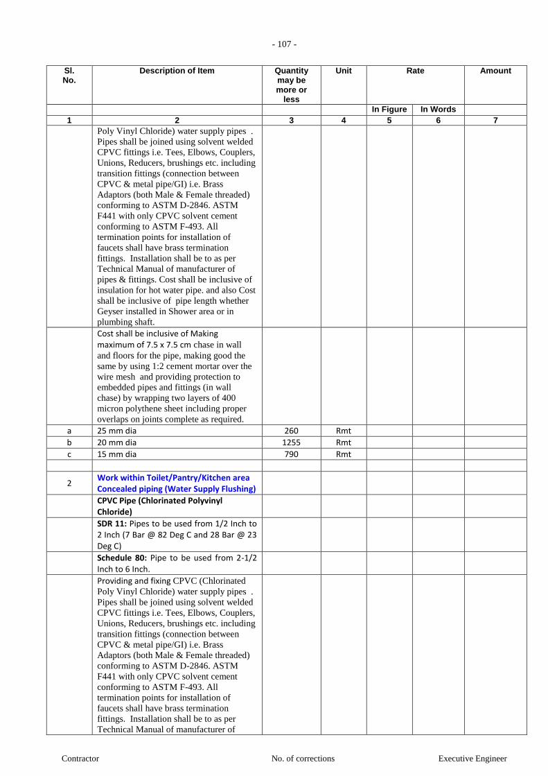
- 107 -
Contractor No. of corrections Executive Engineer
Sl. No.
Description of Item Quantity may be more or
less
Unit Rate Amount
In Figure In Words 1 2 3 4 5 6 7
Poly Vinyl Chloride) water supply pipes .
Pipes shall be joined using solvent welded
CPVC fittings i.e. Tees, Elbows, Couplers,
Unions, Reducers, brushings etc. including
transition fittings (connection between
CPVC & metal pipe/GI) i.e. Brass
Adaptors (both Male & Female threaded)
conforming to ASTM D-2846. ASTM
F441 with only CPVC solvent cement
conforming to ASTM F-493. All
termination points for installation of
faucets shall have brass termination
fittings. Installation shall be to as per
Technical Manual of manufacturer of
pipes & fittings. Cost shall be inclusive of
insulation for hot water pipe. and also Cost
shall be inclusive of pipe length whether
Geyser installed in Shower area or in
plumbing shaft.
Cost shall be inclusive of Making maximum of 7.5 x 7.5 cm chase in wall
and floors for the pipe, making good the
same by using 1:2 cement mortar over the
wire mesh and providing protection to
embedded pipes and fittings (in wall
chase) by wrapping two layers of 400
micron polythene sheet including proper
overlaps on joints complete as required.
a 25 mm dia 260 Rmt
b 20 mm dia 1255 Rmt
c 15 mm dia 790 Rmt
2 Work within Toilet/Pantry/Kitchen area Concealed piping (Water Supply Flushing)
CPVC Pipe (Chlorinated Polyvinyl Chloride)
SDR 11: Pipes to be used from 1/2 Inch to 2 Inch (7 Bar @ 82 Deg C and 28 Bar @ 23 Deg C)
Schedule 80: Pipe to be used from 2-1/2 Inch to 6 Inch.
Providing and fixing CPVC (Chlorinated
Poly Vinyl Chloride) water supply pipes .
Pipes shall be joined using solvent welded
CPVC fittings i.e. Tees, Elbows, Couplers,
Unions, Reducers, brushings etc. including
transition fittings (connection between
CPVC & metal pipe/GI) i.e. Brass
Adaptors (both Male & Female threaded)
conforming to ASTM D-2846. ASTM
F441 with only CPVC solvent cement
conforming to ASTM F-493. All
termination points for installation of
faucets shall have brass termination
fittings. Installation shall be to as per
Technical Manual of manufacturer of

- 108 -
Contractor No. of corrections Executive Engineer
Sl. No.
Description of Item Quantity may be more or
less
Unit Rate Amount
In Figure In Words 1 2 3 4 5 6 7
pipes & fittings. Cost shall be inclusive of
insulation for hot water pipe. and also Cost
shall be inclusive of pipe length whether
Geyser installed in Shower area or in
plumbing shaft.
Cost shall be inclusive of Making maximum of 7.5 x 7.5 cm chase in wall
and floors for the pipe, making good the
same by using 1:2 cement mortar over the
wire mesh and providing protection to
embedded pipes and fittings (in wall
chase) by wrapping two layers of 400
micron polythene sheet including proper
overlaps on joints complete as required.
a 40 mm dia 1010 Rmt
b 32 mm dia 750 Rmt
3 Work within Plumbng Duct (Water Supply Domestic )
uPVC (unplasticized Polyvinyl Chloride) (SCHEDULE 40 / SCHEDULE 80)
Pipes shall be joined using solvent welded UPVC fittings i.e. Tees, Elbows, Couplers, Unions, Reducers, brushings etc. including transition fittings (connection between UPVC & metal pipe/GI) i.e. Brass Adaptors (both Male & Female threaded) conforming to ASTM D-2846. ASTM F441 with only UPVC solvent cement conforming to ASTM F-493. All termination points for installation of faucets shall have brass termination fittings. Installation shall be to as per Technical Manual of manufacturer of pipes & fittings. Including ball valve, Butterfly valve, PRV,with all fittings i.e. Tee, Elbow, flanges / union, rubber gasket, nuts, bolts, jointing material, washers & painting complete as required.
Cost shall be inclusive of Fixing/supporting the pipes (& fittings) at wall/ceiling level supported by galvanized clamps, hangers etc, as per specification. Exposed pipes to be painted of legends with direction arrow. GI pipe sleeves suitable higher size shall be provided wherever the pipes are crossing the fire rated walls / floors slab and sealing the sleeves with glass wool in between and fire sealant compound at either end all as per Project Manager's / Consultant requirement. All termination points for installation of faucets shall have brass termination fittings. Installation shall be to as per Technical Manual of
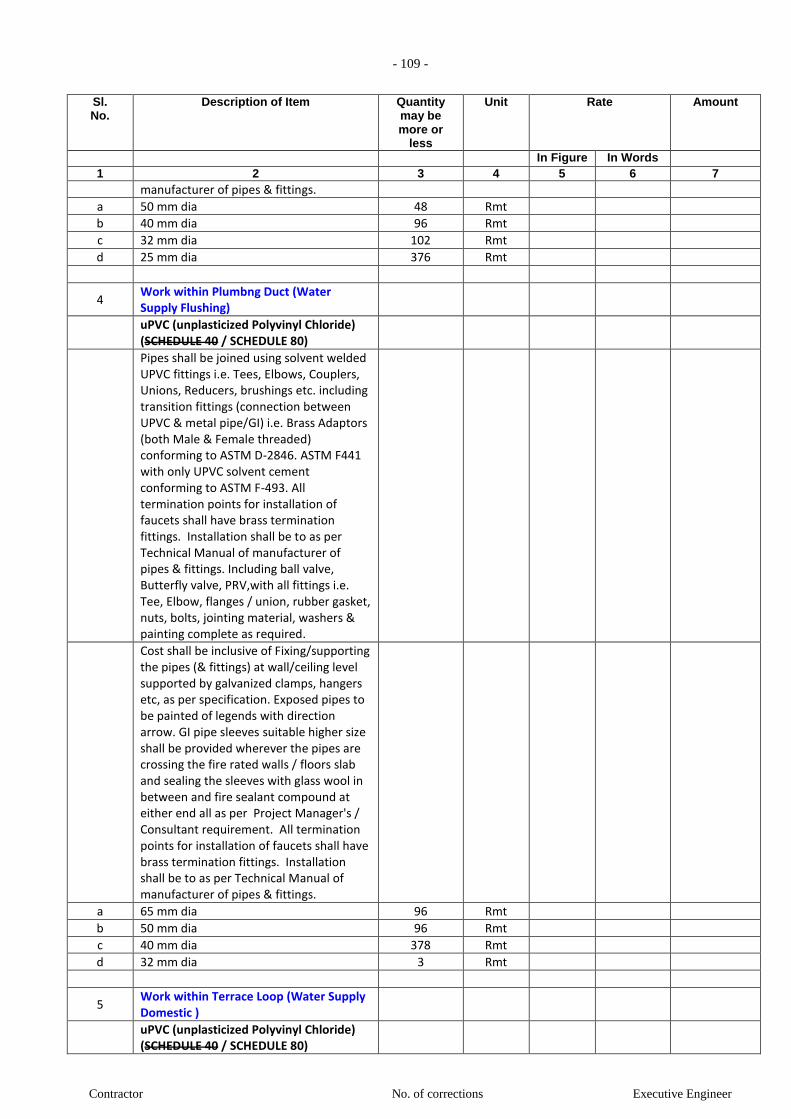
- 109 -
Contractor No. of corrections Executive Engineer
Sl. No.
Description of Item Quantity may be more or
less
Unit Rate Amount
In Figure In Words 1 2 3 4 5 6 7
manufacturer of pipes & fittings.
a 50 mm dia 48 Rmt
b 40 mm dia 96 Rmt
c 32 mm dia 102 Rmt
d 25 mm dia 376 Rmt
4 Work within Plumbng Duct (Water Supply Flushing)
uPVC (unplasticized Polyvinyl Chloride) (SCHEDULE 40 / SCHEDULE 80)
Pipes shall be joined using solvent welded UPVC fittings i.e. Tees, Elbows, Couplers, Unions, Reducers, brushings etc. including transition fittings (connection between UPVC & metal pipe/GI) i.e. Brass Adaptors (both Male & Female threaded) conforming to ASTM D-2846. ASTM F441 with only UPVC solvent cement conforming to ASTM F-493. All termination points for installation of faucets shall have brass termination fittings. Installation shall be to as per Technical Manual of manufacturer of pipes & fittings. Including ball valve, Butterfly valve, PRV,with all fittings i.e. Tee, Elbow, flanges / union, rubber gasket, nuts, bolts, jointing material, washers & painting complete as required.
Cost shall be inclusive of Fixing/supporting the pipes (& fittings) at wall/ceiling level supported by galvanized clamps, hangers etc, as per specification. Exposed pipes to be painted of legends with direction arrow. GI pipe sleeves suitable higher size shall be provided wherever the pipes are crossing the fire rated walls / floors slab and sealing the sleeves with glass wool in between and fire sealant compound at either end all as per Project Manager's / Consultant requirement. All termination points for installation of faucets shall have brass termination fittings. Installation shall be to as per Technical Manual of manufacturer of pipes & fittings.
a 65 mm dia 96 Rmt
b 50 mm dia 96 Rmt
c 40 mm dia 378 Rmt
d 32 mm dia 3 Rmt
5 Work within Terrace Loop (Water Supply Domestic )
uPVC (unplasticized Polyvinyl Chloride) (SCHEDULE 40 / SCHEDULE 80)

- 110 -
Contractor No. of corrections Executive Engineer
Sl. No.
Description of Item Quantity may be more or
less
Unit Rate Amount
In Figure In Words 1 2 3 4 5 6 7
Pipes shall be joined using solvent welded UPVC fittings i.e. Tees, Elbows, Couplers, Unions, Reducers, brushings etc. including transition fittings (connection between UPVC & metal pipe/GI) i.e. Brass Adaptors (both Male & Female threaded) conforming to ASTM D-2846. ASTM F441 with only UPVC solvent cement conforming to ASTM F-493. All termination points for installation of faucets shall have brass termination fittings. Installation shall be to as per Technical Manual of manufacturer of pipes & fittings. Including ball valve, Butterfly valve, PRV,with all fittings i.e. Tee, Elbow, flanges / union, rubber gasket, nuts, bolts, jointing material, washers & painting complete as required.
Cost shall be inclusive of Fixing/supporting the pipes (& fittings) at wall/ceiling level supported by galvanized clamps, hangers etc, as per specification. Exposed pipes to be painted of legends with direction arrow. GI pipe sleeves suitable higher size shall be provided wherever the pipes are crossing the fire rated walls / floors slab and sealing the sleeves with glass wool in between and fire sealant compound at either end all as per Project Manager's / Consultant requirement. All termination points for installation of faucets shall have brass termination fittings. Installation shall be to as per Technical Manual of manufacturer of pipes & fittings.
a 80 mm dia 125 Rmt
6 Work within Terrace Loop (Water Supply Flushing)
uPVC (unplasticized Polyvinyl Chloride) (SCHEDULE 40 / SCHEDULE 80)
Pipes shall be joined using solvent welded UPVC fittings i.e. Tees, Elbows, Couplers, Unions, Reducers, brushings etc. including transition fittings (connection between UPVC & metal pipe/GI) i.e. Brass Adaptors (both Male & Female threaded) conforming to ASTM D-2846. ASTM F441 with only UPVC solvent cement conforming to ASTM F-493. All termination points for installation of faucets shall have brass termination fittings. Installation shall be to as per Technical Manual of manufacturer of

- 111 -
Contractor No. of corrections Executive Engineer
Sl. No.
Description of Item Quantity may be more or
less
Unit Rate Amount
In Figure In Words 1 2 3 4 5 6 7
pipes & fittings. Including ball valve, Butterfly valve, PRV,with all fittings i.e. Tee, Elbow, flanges / union, rubber gasket, nuts, bolts, jointing material, washers & painting complete as required.
Cost shall be inclusive of Fixing/supporting the pipes (& fittings) at wall/ceiling level supported by galvanized clamps, hangers etc, as per specification. Exposed pipes to be painted of legends with direction arrow. GI pipe sleeves suitable higher size shall be provided wherever the pipes are crossing the fire rated walls / floors slab and sealing the sleeves with glass wool in between and fire sealant compound at either end all as per Project Manager's / Consultant requirement. All termination points for installation of faucets shall have brass termination fittings. Installation shall be to as per Technical Manual of manufacturer of pipes & fittings.
a 80 mm dia 125 Rmt
7 VALVES in Terrace & Plumbing Duct (For Domestic and Flushing)
7.1 Ball Valve
Providing and fixing ball valve including
flanges / union, etc. complete as required.
Tested pressure = 15 Kg / Sqcm
Material : Brass
a 20 mm n.b 4 NOS.
b 25 mm n.b 45 NOS.
c 32 mm n.b 4 NOS.
d 40 mm n.b 45 NOS.
e 50 mm n.b 4 NOS.
7.2 Butterfly Valve (Terrace Floor)
Providing & fixing butterfly valve (Body : Grey Cast Iron, Shaft : SS, Disc : SG Iron (Rilson coated), Liner : HT - EPDM) (upto 150mm dia with hand lever operation & above with gear box operation). Including rubber gasket, flanges, nuts, bolts, washers & painting complete as required.
Tested pressure = 15 Kg / Sqcm
Material : Cast Iron
a 65 mm n.b 4 NOS.
7.3 Air Vent valve (Terrace Floor PIPE LOOP)
Providing & fixing Auto Air vent for cold
water supply risers.
Tested pressure = 15 Kg / Sqcm
Material : Cast Iron
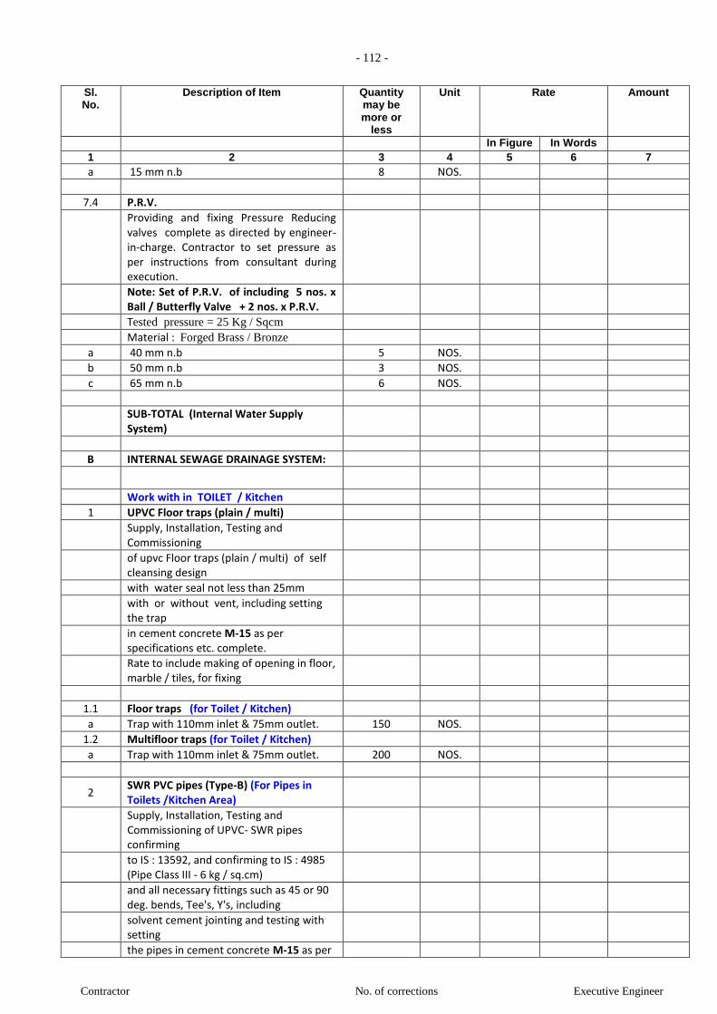
- 112 -
Contractor No. of corrections Executive Engineer
Sl. No.
Description of Item Quantity may be more or
less
Unit Rate Amount
In Figure In Words 1 2 3 4 5 6 7
a 15 mm n.b 8 NOS.
7.4 P.R.V.
Providing and fixing Pressure Reducing valves complete as directed by engineer-in-charge. Contractor to set pressure as per instructions from consultant during execution.
Note: Set of P.R.V. of including 5 nos. x Ball / Butterfly Valve + 2 nos. x P.R.V.
Tested pressure = 25 Kg / Sqcm
Material : Forged Brass / Bronze
a 40 mm n.b 5 NOS.
b 50 mm n.b 3 NOS.
c 65 mm n.b 6 NOS.
SUB-TOTAL (Internal Water Supply System)
B INTERNAL SEWAGE DRAINAGE SYSTEM:
Work with in TOILET / Kitchen
1 UPVC Floor traps (plain / multi)
Supply, Installation, Testing and Commissioning
of upvc Floor traps (plain / multi) of self cleansing design
with water seal not less than 25mm
with or without vent, including setting the trap
in cement concrete M-15 as per specifications etc. complete.
Rate to include making of opening in floor, marble / tiles, for fixing
1.1 Floor traps (for Toilet / Kitchen)
a Trap with 110mm inlet & 75mm outlet. 150 NOS.
1.2 Multifloor traps (for Toilet / Kitchen)
a Trap with 110mm inlet & 75mm outlet. 200 NOS.
2 SWR PVC pipes (Type-B) (For Pipes in Toilets /Kitchen Area)
Supply, Installation, Testing and Commissioning of UPVC- SWR pipes confirming
to IS : 13592, and confirming to IS : 4985 (Pipe Class III - 6 kg / sq.cm)
and all necessary fittings such as 45 or 90 deg. bends, Tee's, Y's, including
solvent cement jointing and testing with setting
the pipes in cement concrete M-15 as per
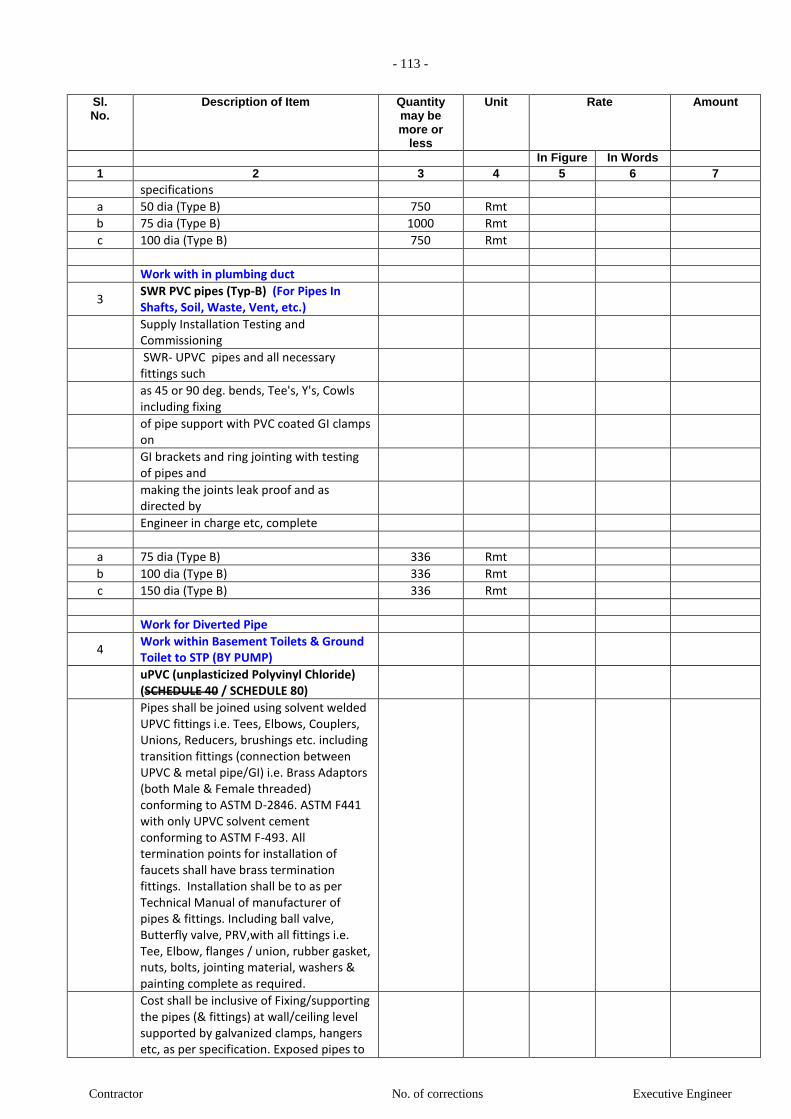
- 113 -
Contractor No. of corrections Executive Engineer
Sl. No.
Description of Item Quantity may be more or
less
Unit Rate Amount
In Figure In Words 1 2 3 4 5 6 7
specifications
a 50 dia (Type B) 750 Rmt
b 75 dia (Type B) 1000 Rmt
c 100 dia (Type B) 750 Rmt
Work with in plumbing duct
3 SWR PVC pipes (Typ-B) (For Pipes In Shafts, Soil, Waste, Vent, etc.)
Supply Installation Testing and Commissioning
SWR- UPVC pipes and all necessary fittings such
as 45 or 90 deg. bends, Tee's, Y's, Cowls including fixing
of pipe support with PVC coated GI clamps on
GI brackets and ring jointing with testing of pipes and
making the joints leak proof and as directed by
Engineer in charge etc, complete
a 75 dia (Type B) 336 Rmt
b 100 dia (Type B) 336 Rmt
c 150 dia (Type B) 336 Rmt
Work for Diverted Pipe
4 Work within Basement Toilets & Ground Toilet to STP (BY PUMP)
uPVC (unplasticized Polyvinyl Chloride) (SCHEDULE 40 / SCHEDULE 80)
Pipes shall be joined using solvent welded UPVC fittings i.e. Tees, Elbows, Couplers, Unions, Reducers, brushings etc. including transition fittings (connection between UPVC & metal pipe/GI) i.e. Brass Adaptors (both Male & Female threaded) conforming to ASTM D-2846. ASTM F441 with only UPVC solvent cement conforming to ASTM F-493. All termination points for installation of faucets shall have brass termination fittings. Installation shall be to as per Technical Manual of manufacturer of pipes & fittings. Including ball valve, Butterfly valve, PRV,with all fittings i.e. Tee, Elbow, flanges / union, rubber gasket, nuts, bolts, jointing material, washers & painting complete as required.
Cost shall be inclusive of Fixing/supporting the pipes (& fittings) at wall/ceiling level supported by galvanized clamps, hangers etc, as per specification. Exposed pipes to
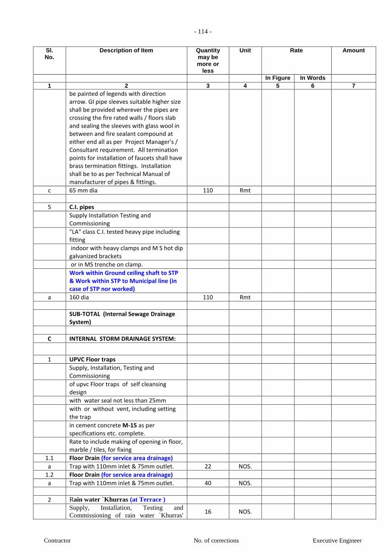
- 114 -
Contractor No. of corrections Executive Engineer
Sl. No.
Description of Item Quantity may be more or
less
Unit Rate Amount
In Figure In Words 1 2 3 4 5 6 7
be painted of legends with direction arrow. GI pipe sleeves suitable higher size shall be provided wherever the pipes are crossing the fire rated walls / floors slab and sealing the sleeves with glass wool in between and fire sealant compound at either end all as per Project Manager's / Consultant requirement. All termination points for installation of faucets shall have brass termination fittings. Installation shall be to as per Technical Manual of manufacturer of pipes & fittings.
c 65 mm dia 110 Rmt
5 C.I. pipes
Supply Installation Testing and Commissioning
"LA" class C.I. tested heavy pipe including fitting
indoor with heavy clamps and M S hot dip galvanized brackets
or in MS trenche on clamp.
Work within Ground ceiling shaft to STP & Work within STP to Municipal line (in case of STP nor worked)
a 160 dia 110 Rmt
SUB-TOTAL (Internal Sewage Drainage System)
C INTERNAL STORM DRAINAGE SYSTEM:
1 UPVC Floor traps
Supply, Installation, Testing and Commissioning
of upvc Floor traps of self cleansing design
with water seal not less than 25mm
with or without vent, including setting the trap
in cement concrete M-15 as per specifications etc. complete.
Rate to include making of opening in floor, marble / tiles, for fixing
1.1 Floor Drain (for service area drainage)
a Trap with 110mm inlet & 75mm outlet. 22 NOS.
1.2 Floor Drain (for service area drainage)
a Trap with 110mm inlet & 75mm outlet. 40 NOS.
2 Rain water `Khurras (at Terrace )
Supply, Installation, Testing and
Commissioning of rain water `Khurras' 16 NOS.

- 115 -
Contractor No. of corrections Executive Engineer
Sl. No.
Description of Item Quantity may be more or
less
Unit Rate Amount
In Figure In Words 1 2 3 4 5 6 7
required depth with lead flashing around
the pipe with one piece lead sheet of 3 mm
thick set on a layer of cold bitumen.
3 PVC Heavy grating (at Terrace )
Supply, Installation, Testing and Commissioning of
Heavy grating at the collection point of rain water pipe on terrace with material and labour etc. complete as per directions of engineer-in-charge.
a 100 mm for 75 dia Pipe 62 NOS.
b 230 mm for 150 dia Pipe 16 NOS.
4 SWR PVC pipes (Typ-B) (Work with in Service area drainage)
Supply, Installation, Testing and Commissioning of
SWR-UPVC pipes and all necessary fittings such
as 45 or 90 deg. bends, Tee's, Y's, access pipe including fixing pipe
support with PVC coated GI clamps on GI brackets and
ring / solvent jointing with testing of pipes and making the
joints leak proof and as directed by Engineer in charge
etc complete.
a 75 dia 33 Rmt
5 SWR PVC pipes (Typ-B) (Work with in plumbing duct)
Supply, Installation, Testing and Commissioning of
SWR-UPVC pipes and all necessary fittings such
as 45 or 90 deg. bends, Tee's, Y's, access pipe including fixing pipe
support with PVC coated GI clamps on GI brackets and
ring / solvent jointing with testing of pipes and making the
joints leak proof and as directed by Engineer in charge
etc complete.
a 150 dia 1392 Rmt
6 SWR PVC pipes (Typ-B) (Work with in Basement Floor drainage)
Supply, Installation, Testing and Commissioning of
SWR-UPVC pipes and all necessary fittings

- 116 -
Contractor No. of corrections Executive Engineer
Sl. No.
Description of Item Quantity may be more or
less
Unit Rate Amount
In Figure In Words 1 2 3 4 5 6 7
such
as 45 or 90 deg. bends, Tee's, Y's, access pipe including fixing pipe
support with PVC coated GI clamps on GI brackets and
ring / solvent jointing with testing of pipes and making the
joints leak proof and as directed by Engineer in charge
etc complete.
a 75 dia 260 Rmt
Work for Diverted Pipe
7 C.I. pipes (Work within Basement Ceiling To Ground Chamber)
Supply Installation Testing and Commissioning
"LA" class C.I. tested heavy pipe including fitting
indoor with heavy clamps and M S hot dip galvanized brackets
or in MS trenche on clamp.
a 210 dia 300 Rmt
8 Work within 3rd Basement to ground for Car Pit, Sump & Plumbing shaft drainage (BY PUMP)
uPVC (unplasticized Polyvinyl Chloride) (SCHEDULE 40 / SCHEDULE 80)
Pipes shall be joined using solvent welded UPVC fittings i.e. Tees, Elbows, Couplers, Unions, Reducers, brushings etc. including transition fittings (connection between UPVC & metal pipe/GI) i.e. Brass Adaptors (both Male & Female threaded) conforming to ASTM D-2846. ASTM F441 with only UPVC solvent cement conforming to ASTM F-493. All termination points for installation of faucets shall have brass termination fittings. Installation shall be to as per Technical Manual of manufacturer of pipes & fittings. Including ball valve, Butterfly valve, PRV,with all fittings i.e. Tee, Elbow, flanges / union, rubber gasket, nuts, bolts, jointing material, washers & painting complete as required.
Cost shall be inclusive of Fixing/supporting the pipes (& fittings) at wall/ceiling level supported by galvanized clamps, hangers etc, as per specification. Exposed pipes to be painted of legends with direction arrow. GI pipe sleeves suitable higher size
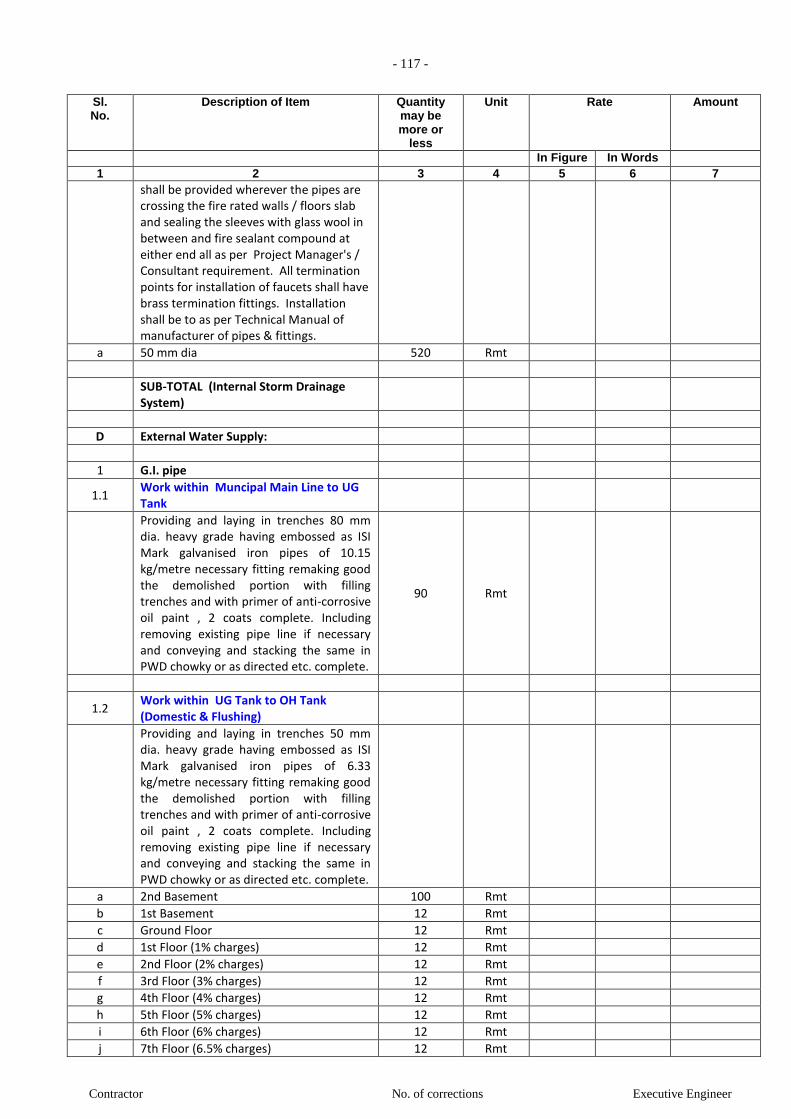
- 117 -
Contractor No. of corrections Executive Engineer
Sl. No.
Description of Item Quantity may be more or
less
Unit Rate Amount
In Figure In Words 1 2 3 4 5 6 7
shall be provided wherever the pipes are crossing the fire rated walls / floors slab and sealing the sleeves with glass wool in between and fire sealant compound at either end all as per Project Manager's / Consultant requirement. All termination points for installation of faucets shall have brass termination fittings. Installation shall be to as per Technical Manual of manufacturer of pipes & fittings.
a 50 mm dia 520 Rmt
SUB-TOTAL (Internal Storm Drainage System)
D External Water Supply:
1 G.I. pipe
1.1 Work within Muncipal Main Line to UG Tank
Providing and laying in trenches 80 mm dia. heavy grade having embossed as ISI Mark galvanised iron pipes of 10.15 kg/metre necessary fitting remaking good the demolished portion with filling trenches and with primer of anti-corrosive oil paint , 2 coats complete. Including removing existing pipe line if necessary and conveying and stacking the same in PWD chowky or as directed etc. complete.
90 Rmt
1.2 Work within UG Tank to OH Tank (Domestic & Flushing)
Providing and laying in trenches 50 mm dia. heavy grade having embossed as ISI Mark galvanised iron pipes of 6.33 kg/metre necessary fitting remaking good the demolished portion with filling trenches and with primer of anti-corrosive oil paint , 2 coats complete. Including removing existing pipe line if necessary and conveying and stacking the same in PWD chowky or as directed etc. complete.
a 2nd Basement 100 Rmt
b 1st Basement 12 Rmt
c Ground Floor 12 Rmt
d 1st Floor (1% charges) 12 Rmt
e 2nd Floor (2% charges) 12 Rmt
f 3rd Floor (3% charges) 12 Rmt
g 4th Floor (4% charges) 12 Rmt
h 5th Floor (5% charges) 12 Rmt
i 6th Floor (6% charges) 12 Rmt
j 7th Floor (6.5% charges) 12 Rmt
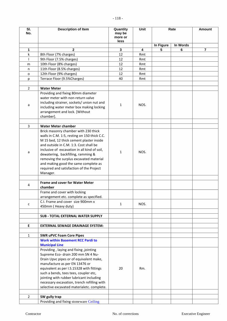
- 118 -
Contractor No. of corrections Executive Engineer
Sl. No.
Description of Item Quantity may be more or
less
Unit Rate Amount
In Figure In Words 1 2 3 4 5 6 7
k 8th Floor (7% charges) 12 Rmt
l 9th Floor (7.5% charges) 12 Rmt
m 10th Floor (8% charges) 12 Rmt
n 11th Floor (8.5% charges) 12 Rmt
o 12th Floor (9% charges) 12 Rmt
p Terrace Floor (9.5%Charges) 40 Rmt
2 Water Meter
a
Providing and fixing 80mm diameter water meter with non-return valve including strainer, sockets/ union nut and including water meter box making locking arrangement and lock. [Without chamber].
1 NOS.
3 Water Meter chamber
a
Brick masonry chamber with 230 thick walls in C.M. 1:5, resting on 150 thick C.C. M 15 bed, 12 thick cement plaster inside and outside in C.M. 1:3. Cost shall be inclusive of excavation in all kind of soil, dewatering, backfilling, ramming & removing the surplus excavated material and making good the same complete as required and satisfaction of the Project Manager.
1 NOS.
4 Frame and cover for Water Meter chamber
Frame and cover with locking arrangement etc. complete as specified.
c C.I. Frame and cover size 900mm x 450mm ( Heavy duty)
1 NOS.
SUB - TOTAL EXTERNAL WATER SUPPLY
E EXTERNAL SEWAGE DRAINAGE SYSTEM:
1 SWR uPVC Foam Core Pipes
Work within Basement RCC Pardi to Municipal Line
Providing , laying and fixing ,jointing Supreme Eco- drain 200 mm SN 4 Nu- Drain Upvc pipes or of equivalent make, manufacture as per EN 13476 or equivalent as per I.S.15328 with fittings such a bends, tees tees, coupler etc, jointing with rubber lubricant including necessary excavation, trench refilling with selective excavated materialetc. complete.
20 Rm.
2 SW gully trap
Providing and fixing stoneware Ceiling

- 119 -
Contractor No. of corrections Executive Engineer
Sl. No.
Description of Item Quantity may be more or
less
Unit Rate Amount
In Figure In Words 1 2 3 4 5 6 7
suspended gully trap at ceiling level.
Making necessary connections &
providing water tight C.I. / D.I. cover with
frame of suitable size.
Cost shall be inclusive of Fixing/supporting the pipes (& fittings) at wall/ceiling level supported by galvanized clamps, hangers etc, as per specification. Exposed pipes to be painted of legends with direction arrow. GI pipe sleeves suitable higher size shall be provided wherever the pipes are crossing the fire rated walls / floors slab and sealing the sleeves with glass wool in between and fire sealant compound at either end all as per Project Manager's / Consultant requirement. All termination points for installation of faucets shall have brass termination fittings. Installation shall be to as per Technical Manual of manufacturer of pipes & fittings.
a 450 x 450mm chamber with 150 x 100mm size `P' trap
4 Nos.
3 IC Chamber / Inspection Chamber
Providing and constructing Brick Masonry inspection Chamber 90cm x 45cm including 1:4:8 C.C foundation, 1:2:4 C.C.channels/half round glazed stoneware pipe channel, salt glazed stone-ware intercepting trap with rodding pipe set in 1:4:8 cement concrete block, brick masonry plastering inside and Outside, with C.I. lead cover of 75 kg with frame fixed in cement concrete.
3 Nos.
Contractor shall submit the structural design and drawings for the approval of Project Manager prior to execution.
4 Sewer Trap
Providing, laying, testing and commissioning of Sewer Trap in CC 1:2:4 as diverted and as specified.
a Sewer Trap (150 x 230mm ) 1 Nos.
SUB-TOTAL (EXTERNAL SEWAGE DRAINAGE SYSTEM)
F EXTERNAL STORM DRAINAGE SYSTEM:
1 SWR uPVC Foam Core Pipes
1.1 Work within Ground Floor all round drainage
Providing , laying and fixing ,jointing 250 Rm.
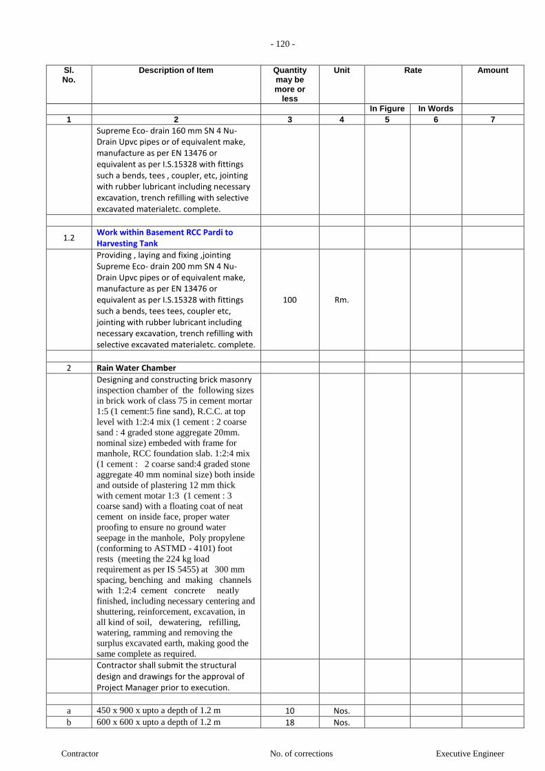
- 120 -
Contractor No. of corrections Executive Engineer
Sl. No.
Description of Item Quantity may be more or
less
Unit Rate Amount
In Figure In Words 1 2 3 4 5 6 7
Supreme Eco- drain 160 mm SN 4 Nu- Drain Upvc pipes or of equivalent make, manufacture as per EN 13476 or equivalent as per I.S.15328 with fittings such a bends, tees , coupler, etc, jointing with rubber lubricant including necessary excavation, trench refilling with selective excavated materialetc. complete.
1.2 Work within Basement RCC Pardi to Harvesting Tank
Providing , laying and fixing ,jointing Supreme Eco- drain 200 mm SN 4 Nu- Drain Upvc pipes or of equivalent make, manufacture as per EN 13476 or equivalent as per I.S.15328 with fittings such a bends, tees tees, coupler etc, jointing with rubber lubricant including necessary excavation, trench refilling with selective excavated materialetc. complete.
100 Rm.
2 Rain Water Chamber
Designing and constructing brick masonry inspection chamber of the following sizes
in brick work of class 75 in cement mortar
1:5 (1 cement:5 fine sand), R.C.C. at top
level with 1:2:4 mix (1 cement : 2 coarse
sand : 4 graded stone aggregate 20mm.
nominal size) embeded with frame for
manhole, RCC foundation slab. 1:2:4 mix
(1 cement : 2 coarse sand:4 graded stone
aggregate 40 mm nominal size) both inside
and outside of plastering 12 mm thick
with cement motar 1:3 (1 cement : 3
coarse sand) with a floating coat of neat
cement on inside face, proper water
proofing to ensure no ground water
seepage in the manhole, Poly propylene
(conforming to ASTMD - 4101) foot
rests (meeting the 224 kg load
requirement as per IS 5455) at 300 mm
spacing, benching and making channels
with 1:2:4 cement concrete neatly
finished, including necessary centering and
shuttering, reinforcement, excavation, in
all kind of soil, dewatering, refilling,
watering, ramming and removing the
surplus excavated earth, making good the
same complete as required.
Contractor shall submit the structural design and drawings for the approval of Project Manager prior to execution.
a 450 x 900 x upto a depth of 1.2 m 10 Nos.
b 600 x 600 x upto a depth of 1.2 m 18 Nos.
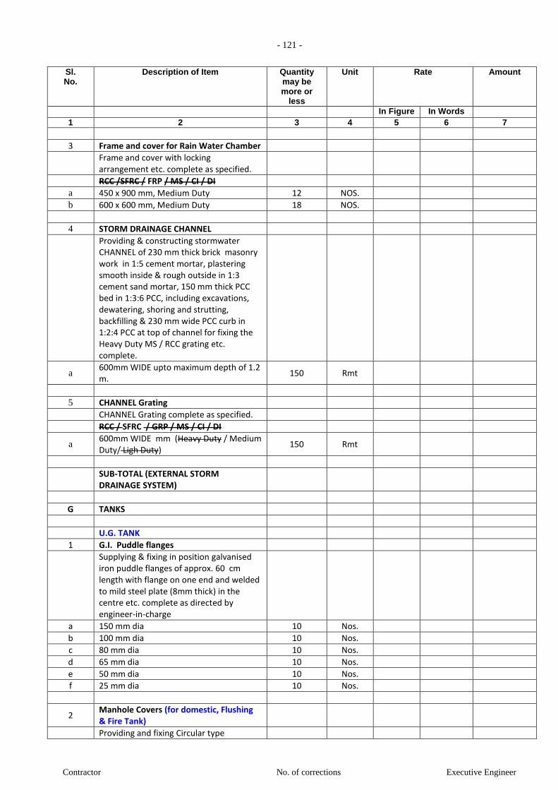
- 121 -
Contractor No. of corrections Executive Engineer
Sl. No.
Description of Item Quantity may be more or
less
Unit Rate Amount
In Figure In Words 1 2 3 4 5 6 7
3 Frame and cover for Rain Water Chamber
Frame and cover with locking arrangement etc. complete as specified.
RCC /SFRC / FRP / MS / CI / DI
a 450 x 900 mm, Medium Duty 12 NOS.
b 600 x 600 mm, Medium Duty 18 NOS.
4 STORM DRAINAGE CHANNEL
Providing & constructing stormwater CHANNEL of 230 mm thick brick masonry work in 1:5 cement mortar, plastering smooth inside & rough outside in 1:3 cement sand mortar, 150 mm thick PCC bed in 1:3:6 PCC, including excavations, dewatering, shoring and strutting, backfilling & 230 mm wide PCC curb in 1:2:4 PCC at top of channel for fixing the Heavy Duty MS / RCC grating etc. complete.
a 600mm WIDE upto maximum depth of 1.2 m.
150 Rmt
5 CHANNEL Grating
CHANNEL Grating complete as specified.
RCC / SFRC / GRP / MS / CI / DI
a 600mm WIDE mm (Heavy Duty / Medium Duty/ Ligh Duty)
150 Rmt
SUB-TOTAL (EXTERNAL STORM DRAINAGE SYSTEM)
G TANKS
U.G. TANK
1 G.I. Puddle flanges
Supplying & fixing in position galvanised iron puddle flanges of approx. 60 cm length with flange on one end and welded to mild steel plate (8mm thick) in the centre etc. complete as directed by engineer-in-charge
a 150 mm dia 10 Nos.
b 100 mm dia 10 Nos.
c 80 mm dia 10 Nos.
d 65 mm dia 10 Nos.
e 50 mm dia 10 Nos.
f 25 mm dia 10 Nos.
2 Manhole Covers (for domestic, Flushing & Fire Tank)
Providing and fixing Circular type

- 122 -
Contractor No. of corrections Executive Engineer
Sl. No.
Description of Item Quantity may be more or
less
Unit Rate Amount
In Figure In Words 1 2 3 4 5 6 7
Manhole Covers with frame of approved make of 525 mm dia including all necessary supports, grouting of the frame in RCC, etc. complete as directed by engineer-in-charge.
RCC /SFRC / FRP / MS / CI / DI
a 600 mm, Medium Duty 6 NOS.
3 Vapour vent pipes (for Domestic & Flushing Tank)
Supply & installation of vapour vent pipes
with Tee, Elbow, Pvc Mosquito proof jali including
required jointing material etc. complete.
(1 set = 2'' pipe + 1 Tee + 2 Elbow + 2 mosquito jali)
a 50 mm n.b. 6 Rmt
4 Overflow and Drain pipes ("C" class G.I. pipe ) (for Domestic & Flushing Tank)
Supply & installation of overflow and drain pipes
of 50mm with Elbow, Plug, Pvc Mosquito proof jali
including required jointing material etc. complete.
for under ground and over head water
tanks
a 80 mm n.b 20 Rmt
10 Butterfly Valve (OH Tank outlet & Drain)
Providing & fixing butterfly valve (Body :
Grey Cast Iron, Shaft : SS, Disc : SG Iron
(Rilson coated), Liner : HT - EPDM) (upto
150mm dia with hand lever operation &
above with gear box operation). Including
rubber gasket, flanges, nuts, bolts, washers
& painting complete as required.
Tested pressure = 15 Kg / Sqcm
Material : Cast Iron
a 65 mm n.b 2 NOS.
b 80 mm n.b 2 NOS.
11 Y-Strainer (For OH Tank outlet)
Providing & fixing Y-Strainer complete as
required.
Tested pressure = 15 Kg / Sqcm
Material : Cast Iron
a 65 mm n.b 1 NOS.
b 80 mm n.b 1 NOS.
c 100 mm n.b NOS.
12 G. M. S. Ladder (From Terrace to O.H.
Tank)
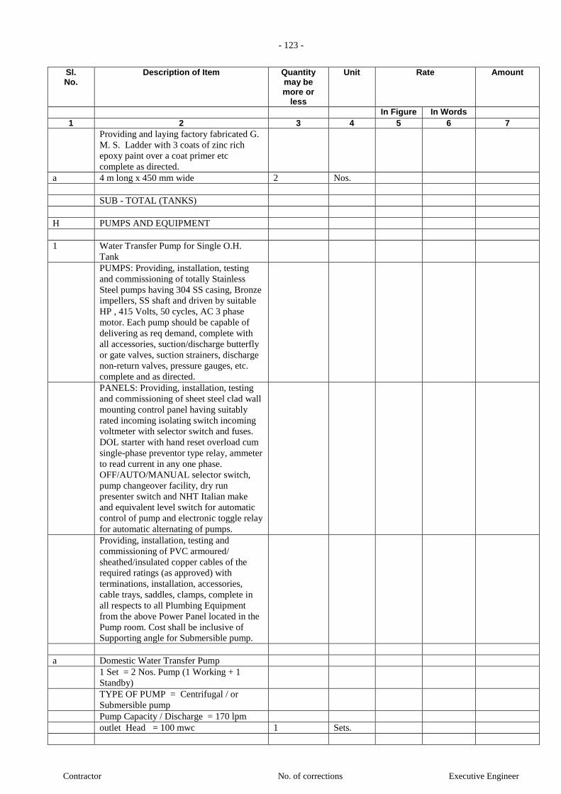
- 123 -
Contractor No. of corrections Executive Engineer
Sl. No.
Description of Item Quantity may be more or
less
Unit Rate Amount
In Figure In Words 1 2 3 4 5 6 7
Providing and laying factory fabricated G.
M. S. Ladder with 3 coats of zinc rich
epoxy paint over a coat primer etc
complete as directed.
a 4 m long x 450 mm wide 2 Nos.
SUB - TOTAL (TANKS)
H PUMPS AND EQUIPMENT
1 Water Transfer Pump for Single O.H.
Tank
PUMPS: Providing, installation, testing
and commissioning of totally Stainless
Steel pumps having 304 SS casing, Bronze
impellers, SS shaft and driven by suitable
HP , 415 Volts, 50 cycles, AC 3 phase
motor. Each pump should be capable of
delivering as req demand, complete with
all accessories, suction/discharge butterfly
or gate valves, suction strainers, discharge
non-return valves, pressure gauges, etc.
complete and as directed.
PANELS: Providing, installation, testing
and commissioning of sheet steel clad wall
mounting control panel having suitably
rated incoming isolating switch incoming
voltmeter with selector switch and fuses.
DOL starter with hand reset overload cum
single-phase preventor type relay, ammeter
to read current in any one phase.
OFF/AUTO/MANUAL selector switch,
pump changeover facility, dry run
presenter switch and NHT Italian make
and equivalent level switch for automatic
control of pump and electronic toggle relay
for automatic alternating of pumps.
Providing, installation, testing and
commissioning of PVC armoured/
sheathed/insulated copper cables of the
required ratings (as approved) with
terminations, installation, accessories,
cable trays, saddles, clamps, complete in
all respects to all Plumbing Equipment
from the above Power Panel located in the
Pump room. Cost shall be inclusive of
Supporting angle for Submersible pump.
a Domestic Water Transfer Pump
1 Set = 2 Nos. Pump (1 Working + 1
Standby)
TYPE OF PUMP = Centrifugal / or
Submersible pump
Pump Capacity / Discharge = 170 lpm
outlet Head = 100 mwc 1 Sets.

- 124 -
Contractor No. of corrections Executive Engineer
Sl. No.
Description of Item Quantity may be more or
less
Unit Rate Amount
In Figure In Words 1 2 3 4 5 6 7
b Flushing Water Transfer Pump
1 Set = 2 Nos. Pump (1 Working + 1
Standby)
TYPE OF PUMP = Centrifugal / or
Submersible pump
Pump Capacity / Discharge = 250 lpm
outlet Head = 100 mwc 1 Sets.
c STP Treated Water Transfer Pump
1 Set = 2 Nos. Pump (1 Working + 1
Standby)
TYPE OF PUMP = Centrifugal / or
Submersible pump
Pump Capacity / Discharge = 100 lpm
outlet Head = 100 mwc 1 Sets.
d Rain Water Transfer Pump (For Rain
Water Harvesting Tank)
1 Set = 2 Nos. Pump (1 Working + 1
Standby)
TYPE OF PUMP = Centrifugal / or
Submersible pump
Pump Capacity / Discharge = 100 lpm
outlet Head = 100 mwc 1 Sets.
2 Sump Pump ( For BASEMENT STORM
DRAINAGE SYSTEM / BASEMENT
TOILET SEWAGE DRAINAGE
SYSTEM )
PUMPS: Providing, installation, testing
and commissioning of dewatering sewage
sump pump with motor etc complete and
as directed with necessary accessories and
equipment (valves etc ) including the
pump panel as required. complete with all
accessories, suction/discharge butterfly or
gate valves, suction strainers, discharge
non-return valves, pressure gauges, etc.
complete and as directed.
PANELS: Providing, installation, testing
and commissioning of sheet steel clad wall
mounting control panel having suitably
rated incoming isolating switch incoming
voltmeter with selector switch and fuses.
DOL starter with hand reset overload cum
single-phase preventor type relay, ammeter
to read current in any one phase.
OFF/AUTO/MANUAL selector switch,
pump changeover facility, dry run
presenter switch and NHT Italian make
and equivalent level switch for automatic
control of pump and electronic toggle relay
for automatic alternating of pumps.
Providing, installation, testing and
commissioning of PVC armoured/
sheathed/insulated copper cables of the

- 125 -
Contractor No. of corrections Executive Engineer
Sl. No.
Description of Item Quantity may be more or
less
Unit Rate Amount
In Figure In Words 1 2 3 4 5 6 7
required ratings (as approved) with
terminations, installation, accessories,
cable trays, saddles, clamps, complete in
all respects to all Plumbing Equipment
from the above Power Panel located in the
Pump room. Cost shall be inclusive of
Supporting angle for Submersible pump.
a Sump Pump ( For Car pit Drainage + 4
Plumbing Duct drainage)
(1 working + 1standby)
Pump Capacity / Discharge =50 lpm
outlet Head = 30 mwc 11 Sets.
b Sump Pump ( For Storm Water Drainage
)
(1 working + 1standby)
Pump Capacity / Discharge =50 lpm
outlet Head = 20 mwc 2 Sets.
c Sump Pump ( For Toilet Sewage
Drainage ) Ground Floor & Basement 1
(1 working + 1standby)
Pump Capacity / Discharge =15 lpm
outlet Head = 12 mwc 3 Sets.
(NOTE: Incoming cable to the panel will
be in the scope of the Electrical
Contractor, but the termination of it in the
panel will be in the scope of the Plumbing
Contractor)
SUB-TOTAL ( PUMPS AND
EQUIPMENT)
I Sewage Treatment Plant (STP)
Supply, Installation, Testing and
Commissioning of Sewage Treatment
Plant (STP) and complete as directed with
all accessories.
a 100 KLD 1 Sets.
J Organic Waste Composer
Supply, Installation, Testing and
Commissioning of Organic Waste
Composer (OWC) and complete as
directed with all accessories.
a 500 KG 1 Sets.
K Approval of Plumbing System From Local
Authority
a Liasoning work with Approval of
Plumbing system from local authority and
any other relevant statutory authority at
initial & various other stages of works,
including preparation of report / drawings
1 Lumpsu
m
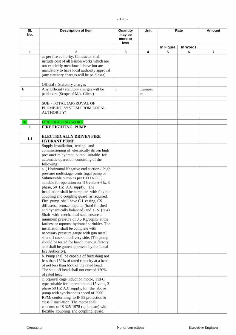
- 126 -
Contractor No. of corrections Executive Engineer
Sl. No.
Description of Item Quantity may be more or
less
Unit Rate Amount
In Figure In Words 1 2 3 4 5 6 7
as per fire authority. Contractor shall
include cost of all liaison works which are
not explicitly mentioned above but are
mandatory to have local authority approval
(any statutory charges will be paid exta)
Official / Statutory charges
b Any Official / statutory charges will be
paid extra (Scope of M/s. Client)
1 Lumpsu
m
SUB - TOTAL (APPROVAL OF
PLUMBING SYSTEM FROM LOCAL
AUTHORITY)
10. FIRE FIGHTING WORK
1 FIRE FIGHTING PUMP
1.1 ELECTRICALLY DRIVEN FIRE
HYDRANT PUMP
Supply Installation, testing and
commissioning of electrically driven high
pressurefire hydrant pump, suitable for
automatic operation consisting of the
following:
a. ( Horizontal Negative end suction / high
pressure multistage, centrifugal pump or
Submersible pump as per CFO NOC ) ,
suitable for operation on 415 volts ± 6%, 3
phase, 50 HZ A.C supply. The
installation shall be complete with flexible
coupling and coupling guard as required.
Fire pump shall have C.I. casing, CS
diffusers, bronze impeller (hard finished
and dynamically balanced) and C.S. (304)
Shaft with mechanical seal, ensure a
minimum pressure of 3.5 Kg/Sqcm at the
farthest or topmost hydrant / sprinkler. The
installation shall be complete with
necessary pressure gauge with gun metal
shut off cock on delivery side. (The pump
should be tested for bench mark at factory
and shall be gotten approved by the Local
fire Authority).
b. Pump shall be capable of furnishing not
less than 150% of rated capacity at a head
of not less than 65% of the rated head.
The shut off head shall not exceed 120%
of rated head.
c. Squirrel cage induction motor, TEFC
type suitable for operation on 415 volts, 3
phase 50 HZ A.C supply, for the above
pump with synchronous speed of 2900
RPM, conforming to IP 55 protection &
class F insulation. The motor shall
conform to IS 325-1978 (up to date) with
flexible coupling and coupling guard,

- 127 -
Contractor No. of corrections Executive Engineer
Sl. No.
Description of Item Quantity may be more or
less
Unit Rate Amount
In Figure In Words 1 2 3 4 5 6 7
complete as required.
d. Common base plate for (a) and (b)
from M.S. Channel for required size.
e. Suitable cement concrete foundation
with cement concrete plaster (design and
drawing to be provided by the Contractor
while the foundation will be done by
others) complete with anti-vibration
arrangement of cushy foot mountings.
a TYPE OF PUMP = Centrifugal / or
Submersible pump
Pump Capacity / Discharge = 2400 lpm
outlet Head = 130 mwc 2 Nos.
1.2 ELECTRICALLY DRIVEN FIRE
SPRINKLER PUMP
Supply Installation, testing and
commissioning of electrically driven high
pressurefire sprinkler pump, suitable for
automatic operation consisting of the
following:
a. ( Horizontal Negative end suction / high
pressure multistage, centrifugal pump or
Submersible pump as per CFO NOC ) ,
suitable for operation on 415 volts ± 6%, 3
phase, 50 HZ A.C supply. The
installation shall be complete with flexible
coupling and coupling guard as required.
Fire pump shall have C.I. casing, CS
diffusers, bronze impeller (hard finished
and dynamically balanced) and C.S. (304)
Shaft with mechanical seal, ensure a
minimum pressure of 3.5 Kg/Sqcm at the
farthest or topmost hydrant / sprinkler. The
installation shall be complete with
necessary pressure gauge with gun metal
shut off cock on delivery side. (The pump
should be tested for bench mark at factory
and shall be gotten approved by the Local
fire Authority).
b. Pump shall be capable of furnishing not
less than 150% of rated capacity at a head
of not less than 65% of the rated head.
The shut off head shall not exceed 120%
of rated head.
c. Squirrel cage induction motor, TEFC
type suitable for operation on 415 volts, 3
phase 50 HZ A.C supply, for the above
pump with synchronous speed of 2900
RPM, conforming to IP 55 protection &
class F insulation. The motor shall
conform to IS 325-1978 (up to date) with
flexible coupling and coupling guard,
complete as required.
d. Common base plate for (a) and (b)
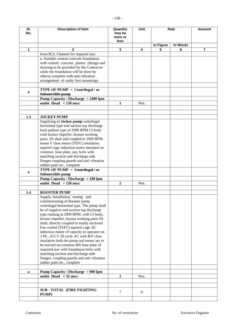
- 128 -
Contractor No. of corrections Executive Engineer
Sl. No.
Description of Item Quantity may be more or
less
Unit Rate Amount
In Figure In Words 1 2 3 4 5 6 7
from M.S. Channel for required size.
e. Suitable cement concrete foundation
with cement concrete plaster (design and
drawing to be provided by the Contractor
while the foundation will be done by
others) complete with anti-vibration
arrangement of cushy foot mountings.
a TYPE OF PUMP = Centrifugal / or
Submersible pump
Pump Capacity / Discharge = 2400 lpm
outlet Head = 130 mwc 1 Nos.
1.3 JOCKEY PUMP
Supplying of Jockey pump centrifugal
horizontal type end suction top discharge
back pullout type of 2900 RPM CI body
with bronze impeller, bronze working
parts, SS shaft and coupled to 2900 RPM
motor F class motor (TEFC) insulation
squirrel cage induction motor mounted on
common base plate, nut, bolts with
matching suction and discharge side
flanges coupling guards and anti vibration
rubber pads etc., complete
a TYPE OF PUMP = Centrifugal / or
Submersible pump
Pump Capacity / Discharge = 180 lpm
outlet Head = 130 mwc 2 Nos.
1.4 BOOSTER PUMP
Supply, Installation, testing and
commissioning of Booster pump
centrifugal horizontal type. The pump shall
be of negative end suction top discharge
type running at 2900 RPM, with CI body,
bronze impeller, bronze working parts SS
shaft, directly coupled to totally enclosed
Fan cooled (TEFC) squirrel cage AC
induction motor of capacity to operator on
3 Ph , 415 V 50 cycle AC with B/F class
insulation both the pump and motor are to
be erected on common MS base plate of
required size with foundation bolts with
matching suction and discharge side
flanges, coupling guards and anti vibration
rubber pads etc., complete
a Pump Capacity / Discharge = 900 lpm
outlet Head = 32 mwc 2 Nos.
SUB - TOTAL (FIRE FIGHTING
PUMP) 7 0

- 129 -
Contractor No. of corrections Executive Engineer
Sl. No.
Description of Item Quantity may be more or
less
Unit Rate Amount
In Figure In Words 1 2 3 4 5 6 7
2 FIRE PUMPS PANEL &
ELECTRICAL WORK
2.1 Fire Pumps Panel
2.1.1 Fire Main Pumps Panel
Supply Installation, testing and
commissioning of automatic Starter panel
switchgear unit for the above Main pump
& jockey and sprinkler pumps , booster
pumps to suit the motor H.P.for the rated
capacity & desired head of the
pumps,comprising of automatic switch
unit, isolator, pressure switches to set
operating pressures, switches rated to 440-
V, 50 HZ supply to continuous maximum
lead & electric supply companies /
IEregulations, contacts of suitable size /
rating terminal boxes for A-AL cables
suitably screwed, standard 250-V,15watt
bayonetcap indicator lamps for the pump
behind ruby domes suitably protected
against damage interlocking arrangements
as per LPA rules and requirements,
auxillary switch / switches to provideaudio
& visual alarm both at pump room & MCP
(Mainfireconsole) with acknowledge
switches & reset switches.Auxilliary
switches to be rated at 5 Amps,250 volts,
50 Hz complete with CT connected
ammeters, voltmeters & 3-ph selector
switches with ON/OFF for reading
currents & voltages to be provided on the
panel. All installation shall comply with
IE rules, TAC/LPA guidelines BSES rules
& NEC etc. complete.
Note:
1) All the components shall be housed in a
common cubicle made of 16 swg. M.S.
sheet with required stiffners ( if required).
Panels shall be powder coated of approved
colour both inside & out side. Panels shall
have both bottom & top cable entry
provisions and panel shall be mounted on
Pedastal of 300 mm height.
2) Panels shall have sufficient (min. 50
Nos) NO/NC contacts for extending the
status( annunciation) of fire pumps to the
Fire alarm panel.
INCOMING
Capacity: xxxA, TPN ACB / MCCB
1 Set of 2000 Amps. TPN Al. Bus bars
with colour coded heat shrinkable PVC
sleeves.
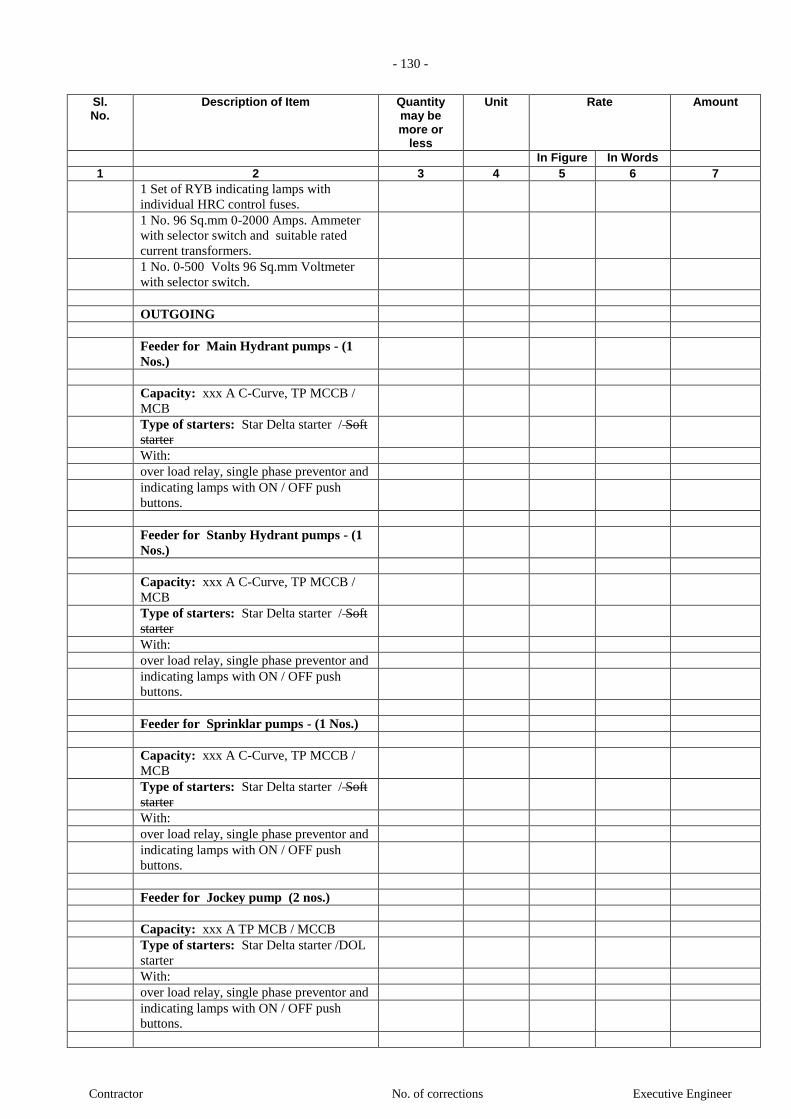
- 130 -
Contractor No. of corrections Executive Engineer
Sl. No.
Description of Item Quantity may be more or
less
Unit Rate Amount
In Figure In Words 1 2 3 4 5 6 7
1 Set of RYB indicating lamps with
individual HRC control fuses.
1 No. 96 Sq.mm 0-2000 Amps. Ammeter
with selector switch and suitable rated
current transformers.
1 No. 0-500 Volts 96 Sq.mm Voltmeter
with selector switch.
OUTGOING
Feeder for Main Hydrant pumps - (1
Nos.)
Capacity: xxx A C-Curve, TP MCCB /
MCB
Type of starters: Star Delta starter / Soft
starter
With:
over load relay, single phase preventor and
indicating lamps with ON / OFF push
buttons.
Feeder for Stanby Hydrant pumps - (1
Nos.)
Capacity: xxx A C-Curve, TP MCCB /
MCB
Type of starters: Star Delta starter / Soft
starter
With:
over load relay, single phase preventor and
indicating lamps with ON / OFF push
buttons.
Feeder for Sprinklar pumps - (1 Nos.)
Capacity: xxx A C-Curve, TP MCCB /
MCB
Type of starters: Star Delta starter / Soft
starter
With:
over load relay, single phase preventor and
indicating lamps with ON / OFF push
buttons.
Feeder for Jockey pump (2 nos.)
Capacity: xxx A TP MCB / MCCB
Type of starters: Star Delta starter /DOL
starter
With:
over load relay, single phase preventor and
indicating lamps with ON / OFF push
buttons.

- 131 -
Contractor No. of corrections Executive Engineer
Sl. No.
Description of Item Quantity may be more or
less
Unit Rate Amount
In Figure In Words 1 2 3 4 5 6 7
Feeder for Booster pumps (1 nos.)
Capacity: xxx A C-Curve, TP MCB
Type of starters: Star Delta starter /DOL
starter
With:
over load relay, single phase preventor and
indicating lamps with ON / OFF push
buttons.
Feeder for for Diesel Engine Pump (0
nos.)
Feeder for Diesel Engine Pump 2 Nos 20
A DPMCC
All above works 1 Nos.
2.1.2 Start / Stop Push Button for Booster
pump
Supply Installation, testing and
commissioning of Emergency Start / Stop
Push Button station weather proof type for
Booster pump at all Floor and terrace
level. 34 Set.
2.2 Cables & Accessories
2.2.1 LT Cable (Power Cabling )
Supply and laying of 1.1kV Voltage
grade, aluminium / copper conductor,
XLPE insulated, steel armoured, power /
control cables. The cables shall be laid in
tray / hume pipe / in ready made trenches,
with nylon cable ties / MS Clamps @
600mm interval etc., as required.
Note:
Two Runs of Cable Due to Star delta
Starter
i Qty. from Fire Pumps Panel to Pump
Aluminium
a 3 Core 70 sq. mm Armoured Aluminium
cable. (100 HP) Mtrs
b 3 Core 50 sq. mm Armoured Aluminium
cable. (75 HP) Mtrs
c 3 Core 35 sq. mm Armoured Aluminium
cable. (60 HP) (Hydrant Pump =1 no +
Sprinklar Pump=1no ) Mtrs
Copper
a 3 Core 50 sq. mm Armoured Copper cable.
(100 HP) Mtrs
b 3 Core 35 sq. mm Armoured Copper cable.
(75 HP) Mtrs
c 3 Core 25 sq. mm Armoured Copper cable.
(60 HP) Mtrs
d 3 Core 16 sq. mm Armoured Copper cable. Mtrs

- 132 -
Contractor No. of corrections Executive Engineer
Sl. No.
Description of Item Quantity may be more or
less
Unit Rate Amount
In Figure In Words 1 2 3 4 5 6 7
(45 HP to 50 HP)
e 3 Core 10 sq. mm Armoured Copper cable.
(35 HP to 40 HP) Mtrs
f 3 Core 6 sq. mm Armoured Copper cable.
(20 HP to 30 HP) Mtrs
g 3 Core 4 sq. mm Armoured Copper cable.
(12.5 HP to 15HP) Mtrs
h
3 Core 2.5 sq. mm Armoured Copper
cable. (Upto 10 HP)
( Booster Pumps = 1no) (Jockey Pumps
= 2nos)
Mtrs
ii Qty. For Control Panel of Diesel Engine
Pump
a 2C x 2.5 Sqmm. Armoured Copper cable
for Diesel engines Mtrs
b 2C x 2.5 Sqmm Armoured Copper cable.
.for Instrumentation Mtrs
iii Qty. For Start / Stop Push Button for
Booster pump
a 3C x 2.5 Sqmm. Armoured Copper cable. Mtrs
iv Qty. For Control Cable of Pressures
switches
2C x 1.5 Sqmm Armoured Copper cable. Mtrs
v All Cables works as per above i to iv 1 Lot
2.2.2 Cable Terminations
Termination of the above cables with
Heavy duty double compression Brass
cable glands & copper heavy duty lugs
with bi metallic rings. (4c/3.5c/3c)
i Qty. from Fire Pumps Panel to Pump
Aluminium
a 3 Core 70 sq. mm Armoured Aluminium
cable. (100 HP) Mtrs
b 3 Core 50 sq. mm Armoured Aluminium
cable. (75 HP) Mtrs
c 3 Core 35 sq. mm Armoured Aluminium
cable. (60 HP) (Hydrant Pump =1 no +
Sprinklar Pump=1no ) Mtrs
Copper
a 3 Core 50 sq. mm Armoured Copper cable.
(100 HP) Nos.
b 3 Core 35 sq. mm Armoured Copper cable.
(75 HP) Nos.
c 3 Core 25 sq. mm Armoured Copper cable.
(60 HP) Nos.
d 3 Core 16 sq. mm Armoured Copper cable.
(45 HP to 50 HP) Nos.
e 3 Core 10 sq. mm Armoured Copper cable.
(35 HP to 40 HP) Nos.
f 3 Core 6 sq. mm Armoured Copper cable. Nos.

- 133 -
Contractor No. of corrections Executive Engineer
Sl. No.
Description of Item Quantity may be more or
less
Unit Rate Amount
In Figure In Words 1 2 3 4 5 6 7
(20 HP to 30 HP)
g 3 Core 4 sq. mm Armoured Copper cable.
(12.5 HP to 15HP) Nos.
h 3 Core 2.5 sq. mm Armoured Copper
cable. (Upto 10 HP) ( Booster
Pumps = 1no) (Jockey Pumps = 2nos) Nos.
ii Qty. For Control Panel of Diesel Engine
Pump
a 2C x 2.5 Sqmm. Armoured Copper cable
for Diesel engines Nos.
b 2C x 2.5 Sqmm Armoured Copper cable.
.for Instrumentation Nos.
iii Qty. For Start / Stop Push Button for
Booster pump
a 3C x 2.5 Sqmm. Armoured Copper cable. Nos.
iv Qty. For Control Cable of Pressures
switches
2C x 1.5 Sqmm Armoured Copper cable. Nos.
v All Cables Terminations works as per
above i to iv 1 Lot
2.2.3 Cable Trays ( Perforated Type)
Supply & installations of Pre Galvanised
60 microns, 2.mm Thick, 50mm height,
readymade Perforated Type cable trays
complete with couplers, bends etc. The
rate to include supports of 25x25mmx3mm
of angle with 10mm verticle rods fixed
with 6mm Anchor fasteners. The vertical
support shall be placed at interval of not
more than 1.5 Metrs & at all bends.
a 200mm wide x 50mm height Mtrs
b 150mm wide x 50mm height Mtrs
c All Cable Trays works as per above i to
iii 1 Lot
2.2.4 Earthing
G.I. Earthing strips of 50mm x 6mm thick,
strip shall run on floor /
ceiling / walls, from the equipment to the
nearest Earth pit with
neccessory accessories as required. 1 Lot
(Scope of M/s. Elect Vendor Scope)
NOTE:
Incoming cable to the panel will be in the
scope of the Electrical Contractor, but the
termination of it in the panel will be in the
scope of the Fire Contractor
SUB - TOTAL (FIRE PUMPS PANEL
& ELECTRICAL WORK) 39
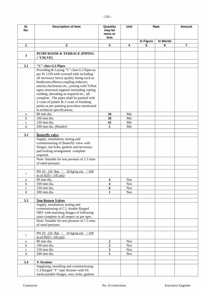
- 134 -
Contractor No. of corrections Executive Engineer
Sl. No.
Description of Item Quantity may be more or
less
Unit Rate Amount
In Figure In Words 1 2 3 4 5 6 7
3 PUMP ROOM & TERRACE (PIPING
+ VALVE)
3.1 "C" class G.I Pipes
Providing & Laying "C" class G.I Pipes as
per IS 1239 with screwed ends including '
all necessary heavy quality fitting such as
bends,tees,elbows,coupling reducers,
unions,checkneuts etc., joining with Teflon
tapes structural supports incluiding cutting
welding ,threading as required etc., all
complete. The pipes shall be painted with
2 coats of primer & 2 coats of finishing
paints as per painting procedure mentioned
in technical specifications.
a 80 mm dia. 30 Mtr
b 100 mm dia. 30 Mtr
c 150 mm dia. 45 Mtr
d 200 mm dia. (Header) 5 Mtr
3.2 Butterfly valve
Supply, installation, testing and
commissioning of Butterfly valve with
flanges, nut bolts, gaskets and necessary
pad locking arrangement complete
required.
Note: Suitable for test pressure of 1.5 time
of rated pressure.
i PN 10 (10 Bar / 10 kg/sq.cm / 100
m of H2O / 145 psi)
a 80 mm dia. 4 Nos
b 100 mm dia. 4 Nos
c 150 mm dia. 6 Nos
d 200 mm dia. 1 Nos
3.3 Non Return Valves
Supply, installation, testing and
commissioning of C.I. double flanged
NRV with matching flanges of following
sizes complete in all respect as per spec.
Note: Suitable for test pressure of 1.5 time
of rated pressure.
i PN 10 (10 Bar / 10 kg/sq.cm / 100
m of H2O / 145 psi)
a 80 mm dia. 2 Nos
b 100 mm dia. 2 Nos
c 150 mm dia. 3 Nos
d 200 mm dia. 1 Nos
3.4 Y-Strainer
Supplying, installing and commissioning
C.I.flanged "Y" type Strainer with SS
mesh,suitable flanges, nuts, bolts, gaskets
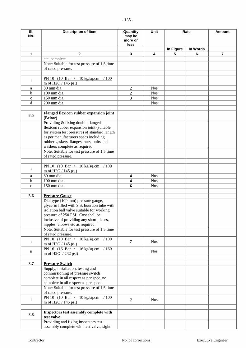
- 135 -
Contractor No. of corrections Executive Engineer
Sl. No.
Description of Item Quantity may be more or
less
Unit Rate Amount
In Figure In Words 1 2 3 4 5 6 7
etc. complete.
Note: Suitable for test pressure of 1.5 time
of rated pressure.
i PN 10 (10 Bar / 10 kg/sq.cm / 100
m of H2O / 145 psi)
a 80 mm dia. 2 Nos
b 100 mm dia. 2 Nos
c 150 mm dia. 3 Nos
d 200 mm dia. Nos
3.5 Flanged flexicon rubber expansion joint
(Below)
Providing & fixing double flanged
flexicon rubber expansion joint (suitable
for system test pressure) of standard length
as per manufacturers specs including
rubber gaskets, flanges, nuts, bolts and
washers complete as required.
Note: Suitable for test pressure of 1.5 time
of rated pressure.
i PN 10 (10 Bar / 10 kg/sq.cm / 100
m of H2O / 145 psi)
a 80 mm dia. 4 Nos
b 100 mm dia. 4 Nos
c 150 mm dia. 6 Nos
3.6 Pressure Gauge
Dial type (100 mm) pressure gauge,
glycerin filled with S.S. bourdon tube with
isolation ball valve suitable for working
pressure of 250 PSI. Cost shall be
inclusive of providing any short pieces,
nipples, elbows etc as required.
Note: Suitable for test pressure of 1.5 time
of rated pressure.
i PN 10 (10 Bar / 10 kg/sq.cm / 100
m of H2O / 145 psi) 7 Nos
ii PN 16 (16 Bar / 16 kg/sq.cm / 160
m of H2O / 232 psi) Nos
3.7 Pressure Switch
Supply, installation, testing and
commissioning of pressure switch
complete in all respect as per spec. no.
complete in all respect as per spec. .
Note: Suitable for test pressure of 1.5 time
of rated pressure.
i PN 10 (10 Bar / 10 kg/sq.cm / 100
m of H2O / 145 psi) 7 Nos
3.8 Inspectors test assembly complete with
test valve
Providing and fixing inspectors test
assembly complete with test valve, sight

- 136 -
Contractor No. of corrections Executive Engineer
Sl. No.
Description of Item Quantity may be more or
less
Unit Rate Amount
In Figure In Words 1 2 3 4 5 6 7
glass sectional drain valve, union with
corrosion resistant orifice all complete
strictly as per drawing. (1 no. for hydrant +
1 no. for sprinkler)
Note: Suitable for test pressure of 1.5 time
of rated pressure.
i PN 10 (10 Bar / 10 kg/sq.cm / 100
m of H2O / 145 psi) 2 Nos
3.9 Control Valve with turbine type
automatic Alarm Gong (for Sprinklers
system)
Providing & Fixing of Installation Control
Valve with turbine type automatic Alarm
Gong to be connected with control valve,
drain & test valve and all other necessary
components as per manufacturer's
specifications complete as required.
a 150 mm dia 1 No.
3.10 Precharged air Vessel (Air Vessle) at
Terrace Level
Providing, fixing, testing and
commissioning of precharged air vessel
(size 450 mm dia & 2000 mm height) for
pressurization of hydrant / sprinkler
system complete with adequate pressure
switches (as per design / requirement) with
valves to operate as per operating
sequences including 25 mm dia drain
valve, air release valve with stop cock on
the top, 25 mm dia inlet with isolating
valve duly painted from inside and outside
complete as required.
1 Set
3.11 Priming Tank (For -ve section)
Providing, fixing, testing &
commissioning of One piece HDP /
Fibrewater Tank for -ve section only
having capcity 1000 lts. Fitted with
necessary accessories.
1 Set
3.12 Float Level Switches
Providing / Fixing Providing, fixing,
jointing and testing in position the
following Top Mounted Guided Float
Level Switches and Electronic Control
Switches including all necessary fittings
required for installation etc.( Make :
Mahalaxmi Instruments) e Project
Manager complete with probes & all
control wiring etc.
Note : Contractor shall include in his rates
for providing level controllers, pressure
switches, wiring, cabling from level
controller / pressure switch to panel etc.
1 Nos

- 137 -
Contractor No. of corrections Executive Engineer
Sl. No.
Description of Item Quantity may be more or
less
Unit Rate Amount
In Figure In Words 1 2 3 4 5 6 7
complete as required to operate the system
automatic/manual. Pump shall be protected
against running dry.
SUB - TOTAL (PUMP ROOM PIPING
AND VALVE)
4 HYDRANT, PIPING &
ACCESSORIES
4.1 GI `C' Heavy class pipe (Non Trenches
)
Providing, laying, jointing, testing and
commissioning of following sizes of GI `C'
Heavy class pipe conforming to IS-1239
with all accessories like all fittings
including tees, elbows, reducers, union,
flanges, rubber gaskets, GI nuts bolts,
washer including supporting/fixing the
pipe on floor / wall /ceiling with clamps,
hangers (using anchor fastners) as per
specification. G.I. pipe sleeve of suitable
higher size shall be provided wherever the
pipes are crossing the walls/floors and
sealing the sleeves with glass wool in
between & fire sealent compound at either
end all as per Project Manager’s /
Consultants requirements including
cutting holes and chases in brick, R.C.C
work and making good the same to
original conditions complete in all
respects. All hangers, clamps, brackets etc.
shall be of galvanized iron unless specified
otherwire and then supply of the same
shall also be included for rates under this
head.. Welding of any kind on the
galvanized support / hanger shall not be
permitted.
Providing two coats of synthetic enamel
paint of approved shade over a coat of
primer. Prior to application of primer the
surface should be cleaned for any dirt,
rusts, rough substance etc. Including
painting of legends both direction arrow
as per the approval of the Project Manager
For wet riser System - GI `C' Heavy class
pipe
a 80 mm dia 350.7 RM
c 150 mm dia 1176 RM
d 200 mm dia RM
4.2 GI `C' Heavy class pipe (In Trenches )
Providing, laying, jointing and testing in
trenches the following sizes of GI class `C'
(heavy class) pipes conforming to IS:1239
with accessories like fittings including

- 138 -
Contractor No. of corrections Executive Engineer
Sl. No.
Description of Item Quantity may be more or
less
Unit Rate Amount
In Figure In Words 1 2 3 4 5 6 7
tees, elbows, reducers, flanges, rubber
gaskets, G.I. nuts, bolts and washers
including excavation in all kind of soil,
refilling, ramming, shoring, removing the
excavated surplus material, providing
adequate support to the pipe and making
good the same complete as required. Rate
shall include for dewatering necessary to
execute the work. The pipe shall not be
less than 1.0 m below ground level at any
point.
Providing protection to embedded GI pipes
and fittings by applying protective primer
(@ 100 gm/sqm) thereafter wrapping 4
mm thick protection coating by thermo
fusion process. Overlap shall be
maintained at 15 mm. The application
process shall be strictly according to
manufacturer’s specification.
c 150 mm dia 42 RM
4.3 Brass Ball Valve
Providing and fixing forged brass ball
valve with forged brass ball
(Cost shall be inclusive of providing
necessary union / flange connection).
Note: Suitable for test pressure of 1.5 time
of rated pressure.
i PN 10 (10 Bar / 10 kg/sq.cm / 100
m of H2O / 145 psi)
a 25 mm dia No.
b 32 mm dia No.
c 40 mm dia No.
d 50 mm dia No.
Ii PN 16 (16 Bar / 16 kg/sq.cm / 160
m of H2O / 232 psi)
a 25 mm dia No.
b 32 mm dia No.
c 40 mm dia No.
d 50 mm dia No.
4.4 Butterfly Valve
Providing & fixing of butterfly valve with
flanges, nut bolts, gaskets and necessary
pad locking arrangement complete
required.
Note: Suitable for test pressure of 1.5 time
of rated pressure.
i PN 10 (10 Bar / 10 kg/sq.cm / 100
m of H2O / 145 psi)
a 80 mm dia 38 No.
4.5 Orifice plate / Pressure reducing disc
SS orifice plate of thickness 5 mm

- 139 -
Contractor No. of corrections Executive Engineer
Sl. No.
Description of Item Quantity may be more or
less
Unit Rate Amount
In Figure In Words 1 2 3 4 5 6 7
complete with identification tag, rubber
insertions, G.I. nuts, G.I. bolts, G.I.
washers etc suitable for following pipe
sizes: a 80 mm dia NB 34 Nos
4.6 External fire hydrant 6
4.6.i Fire hydrant landing valve
Providing & fixing gun metal / SS fire
hydrant single / Double landing valve
with 80 mm N.B. flanged inlet, brass
spindle controlled 63 mm dia female
instantaneous outlet type. G.M. / SS
coupling, blank cap, chain, twist release
type lug & all accessories Conforming to
IS:5290.
Single landing Valve
b SS Material 6 Nos.
4.6.ii "FIRE HOSE" cabinet with Assemble
1 FIRE HOSE cabinet
Providing and fixing weather proof
lockable cabinet of size not less than 0.75
x 0.60 x 0.25 mtr made out of MS sheet of
16 gauge thickness having central opening
and 4 mm thick glazed glass doors two
nos.( 4mm thick glass with rubber
beeding) suitably marked on the outside
with the letters "FIRE HOSE" including
necessary locking arrangement and shall
be painted with one coat of primer and two
coats of synthetic enamel paint of
approved shade. The cabinet shall be
suitable to accommodate 2 nos. or 4 nos
15 mtr long Hose pipe & 1 nos or 2 nos
branch pipe nozzle. It shall be mounted on
raised Brick platform complete as
required. (Cost shall be inclusive of
providing break glass box containing key
for the cabinet along with hammer).
Double Door
a 750 x 600 x 250 (L X W X D) 6 No.
Single Door
b 450 x 450 x 250 (L X W X D) No.
2 Fire Canvas hose pipe
Providing & fixing controlled percolation
fire hose pipe (as per IS:8423) of 63 mm
dia and 15 meter length rated for brust
pressure of 35.7 Kg/sqcm. The hose shall
be tested for flame resistance test in
accordance to IS:8423.
a 63 mm dia and 15 meter lengthx 2 nos. 6 Set
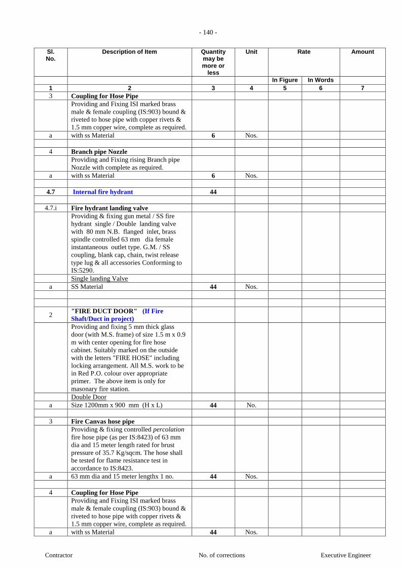
- 140 -
Contractor No. of corrections Executive Engineer
Sl. No.
Description of Item Quantity may be more or
less
Unit Rate Amount
In Figure In Words 1 2 3 4 5 6 7
3 Coupling for Hose Pipe
Providing and Fixing ISI marked brass
male & female coupling (IS:903) bound &
riveted to hose pipe with copper rivets &
1.5 mm copper wire, complete as required.
a with ss Material 6 Nos.
4 Branch pipe Nozzle
Providing and Fixing rising Branch pipe
Nozzle with complete as required.
a with ss Material 6 Nos.
4.7 Internal fire hydrant 44
4.7.i Fire hydrant landing valve
Providing & fixing gun metal / SS fire
hydrant single / Double landing valve
with 80 mm N.B. flanged inlet, brass
spindle controlled 63 mm dia female
instantaneous outlet type. G.M. / SS
coupling, blank cap, chain, twist release
type lug & all accessories Conforming to
IS:5290.
Single landing Valve
a SS Material 44 Nos.
2 "FIRE DUCT DOOR" (If Fire
Shaft/Duct in project)
Providing and fixing 5 mm thick glass
door (with M.S. frame) of size 1.5 m x 0.9
m with center opening for fire hose
cabinet. Suitably marked on the outside
with the letters "FIRE HOSE" including
locking arrangement. All M.S. work to be
in Red P.O. colour over appropriate
primer. The above item is only for
masonary fire station.
Double Door
a Size 1200mm x 900 mm (H x L) 44 No.
3 Fire Canvas hose pipe
Providing & fixing controlled percolation
fire hose pipe (as per IS:8423) of 63 mm
dia and 15 meter length rated for brust
pressure of 35.7 Kg/sqcm. The hose shall
be tested for flame resistance test in
accordance to IS:8423.
a 63 mm dia and 15 meter lengthx 1 no. 44 Nos.
4 Coupling for Hose Pipe
Providing and Fixing ISI marked brass
male & female coupling (IS:903) bound &
riveted to hose pipe with copper rivets &
1.5 mm copper wire, complete as required.
a with ss Material 44 Nos.

- 141 -
Contractor No. of corrections Executive Engineer
Sl. No.
Description of Item Quantity may be more or
less
Unit Rate Amount
In Figure In Words 1 2 3 4 5 6 7
5 Branch pipe Nozzle
Providing and Fixing rising Branch pipe
Nozzle with complete as required.
a with ss Material 44 Nos.
6 Swinging type First hose reel Drum with
Assemble
Providing & fixing swinging type First Aid
hose reel in red colour drum with 30 mts
long and 20 mm dia heavy duty rubber
water hose, 20 mm dia globe valve stop
cock, terminating with G.M. coupling &
nozzle of 6mm outlet with shut off valve
confirming to IS 8090 - 1976 complete
with MS socket for tap-off, drum and
brackets (including painting) for fixing on
wall with anchor fastner, bolts & nuts
conforming to IS:884-1969 complete
as required.
a with ss coupling & nozzle 44 Nos.
4.8 4-way fire brigade connection
Providing & fixing gun-metal fire brigade
connection (suction collecting head)
consisting of 4 Nos. 63 mm dia
instantaneous type male couplings with
built-in check valves, 1 No. 150 mm dia
Butterfly valve, 1 No. 150 mm dia non-
return valve and 150 mm dia flanged
outlet complete with bolts, nuts and rubber
insertions as required and as per IS:904-
1963.
a with Stainless Steel 1 Set
4.9 2-WAY Fire brigade suction hose
Providing & fixing gun-metal fire brigade
suction hose coupling (draw-out
connection) with nut for female coupling
as per IS: 902-1974 complete with 100
mm dia GI suction pipe and 100 mm dia
foot valve (to be connected to static tank).
Provision of GI drop pipe and foot valve
shall be made in all the fire water static
storage tanks (4 Nos) (GI pipe to be paid
separately through appropriate item while
cost of foot valve to be included).
a with Stainless Steel 1 Set
SUB - TOTAL (HYDRANT, PIPING
& ACCESSORIES)
5 SPRINKLER, PIPING &
ACCESSORIES
5.1 GI `C' Heavy class pipe (Non

- 142 -
Contractor No. of corrections Executive Engineer
Sl. No.
Description of Item Quantity may be more or
less
Unit Rate Amount
In Figure In Words 1 2 3 4 5 6 7
Trenches )
Providing, laying, jointing and testing of
following sizes of GI `C' Heavy class
pipe conforming to IS-1239 with all
accessories like all fittings ( all pipes &
fittings shall be forged steel with welded
joint shall be used) including tees, elbows,
reducers, union, flanges, rubber gaskets,
GI nuts bolts, washer including
supporting/fixing the pipe on floor / wall
/ceiling with clamps, hangers (using
anchor fastners) as per specification. G.I.
pipe sleeve of suitable higher size shall be
provided wherever the pipes are crossing
the walls/floors and sealing the sleeves
with glass wool in between & fire sealent
compound at either end all as per Project
Manager’s requirements including cutting
holes and chases in brick, R.C.C work and
making good the same to original
conditions complete in all respects. All
hangers, clamps, brackets etc. shall be of
galvanized iron unless specified otherwise
and the supply of the same shall also be
included in rates under this head. Welding
of any kind on the galvanized support /
hanger shall not be permitted.
Providing two coats of synthetic enamel
paint of approved shade over a coat of
primer. Prior to application of primer the
surface should be cleaned for any dirt,
rusts, rough substance etc. Including
painting of legends both direction arrow
as per the approval of the Project Manager
a 25 mm dia 1585.5 RM
b 32 mm dia 709.8 RM
c 40 mm dia 346.5 RM
d 50 mm dia 346.5 RM
e 65 mm dia 346.5 RM
f 80 mm dia 960.75 RM
g 100 mm dia 441 RM
h 150 mm dia 231 RM
5.2 GI `C' Heavy class pipe (for drainage
purpose )
Providing, fixing, jointing and testing in
position the for drainage purpose
following heavy class (Class C) G.I. pipes
conforming to IS:1239 cut to required
lengths including all necessary fittings
(All fittings shall confirm to IS:1879 (part
1 to 10) and specials such as bends, tees,
unions, Reducers, flanges & plugs etc.
fixing at wall / ceiling level supported by
clamps, hangers (using anchor fastners)

- 143 -
Contractor No. of corrections Executive Engineer
Sl. No.
Description of Item Quantity may be more or
less
Unit Rate Amount
In Figure In Words 1 2 3 4 5 6 7
etc, as per specification. Threading,
jointing, and making proper connections,
cutting hole in wall / floor / slab and
making good the same. GI pipe sleeves
suitable higher size shall be provided
wherever the pipes are crossing the fire
rated walls / floors slab and sealing the
sleeves with glass wool in between and
fire sealent compound at either end all as
per Project Manager's / Consultant
requirement. All hangers, clamps, brackets
etc. shall be of galvanized iron unless
specified otherwise and the supply of the
same shall also be included in rates under
this head. (Fire sealent shall be provided to
the contractor free of cost). Welding of
any kind on the galvanized support /
hanger shall not be permitted.
Providing two coats of synthetic enamel
paint of approved shade over a coat of
primer. Prior to application of primer the
surface should be cleaned for any dirt,
rusts, rough substance etc. Including
painting of legends both direction arrow
as per the approval of the Project Manager
a 25 mm dia 33.6 RM
b 80 mm dia 157.5 RM
5.3 Brass ball valve (for Sprinkler &
drainage)
Providing and fixing forged brass ball
valve with forged brass ball of the
following size including providing
necessary union / flange.
Note: Suitable for test pressure of 1.5 time
of rated pressure.
i PN 10 (10 Bar / 10 kg/sq.cm / 100
m of H2O / 145 psi)
a 25 mm dia 32 No.
5.4 Butterfly valve (for Sprinkler &
drainage)
Providing & fixing of butterfly valve with
flanges, nut bolts & gaskets complete
required. Butterfly valve shall be with pad
locking arrangement.
Note: Suitable for test pressure of 1.5 time
of rated pressure.
i PN 10 (10 Bar / 10 kg/sq.cm / 100
m of H2O / 145 psi)
a 65 mm dia 1 No.
b 80 mm dia 50 No.
c 100 mm dia 29 No.
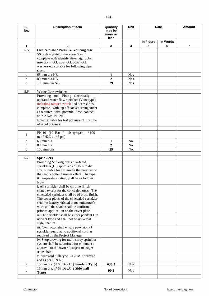
- 144 -
Contractor No. of corrections Executive Engineer
Sl. No.
Description of Item Quantity may be more or
less
Unit Rate Amount
In Figure In Words 1 2 3 4 5 6 7
5.5 Orifice plate / Pressure reducing disc
SS orifice plate of thickness 5 mm
complete with identification tag, rubber
insertions, G.I. nuts, G.I. bolts, G.I.
washers etc suitable for following pipe
sizes:
a 65 mm dia NB 1 Nos
b 80 mm dia NB 2 Nos
c 100 mm dia NB 29 Nos
5.6 Water flow switches
Providing and Fixing electrically
operated water flow switches (Vane type)
including tamper switch and accessories,
complete with tap off socket arrangement
as required, with potential free contact
with 2 Nos. NONC.
Note: Suitable for test pressure of 1.5 time
of rated pressure.
i PN 10 (10 Bar / 10 kg/sq.cm / 100
m of H2O / 145 psi)
a 63 mm dia 1 No.
b 80 mm dia 2 No.
c 100 mm dia 29 No.
5.7 Sprinklers
Providing & fixing brass quartzoid
sprinklers (UL approved) of 15 mm dia
size, suitable for sustaining the pressure on
the seat & water hammer effect. The type
& temperature rating shall be as follows :
Note
i. All sprinkler shall be chrome finish
coated except for the concealed ones. The
concealed sprinkler shall be of brass finish.
The cover plates of the concealed sprinkler
shall be factory painted at manufacturer’s
work and the shade shall be confirmed
prior to application on the cover plate.
ii. The sprinkler shall be either pendent OR
upright type and shall not be universal
style / nature.
iii. Contractor shall ensure provision of
sprinkler guard at no additional cost, as
required by the Project Manager.
iv. Shop drawing for multi spray sprinkler
system shall be submitted for comment /
approval to the owner / project manager
/consultant.
v. quartzoid bulb type UL/FM Approved
and as per IS 9972
a 15 mm dia. @ 68 Deg.C ( Pendent Type) 636.3 Nos
b 15 mm dia. @ 68 Deg.C ( Side wall
Type) 90.3 Nos
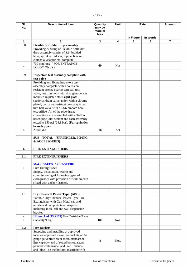
- 145 -
Contractor No. of corrections Executive Engineer
Sl. No.
Description of Item Quantity may be more or
less
Unit Rate Amount
In Figure In Words 1 2 3 4 5 6 7
5.8 Flexible Sprinkler drop assembly
Providing & fixing of Flexible Sprinkler
drop assembly consist of S.S. braided
hose, sprinkler reducer, nipple, bracket,
clamps & adaptor etc. complete.
a 700 mm long ( FOR ENTRANCE
LOBBY ONLY) 60 Nos
5.9 Inspectors test assembly complete with
test valve
Providing and fixing inspectors test
assembly complete with a corrosion
resistant bronze quarter turn ball test
valve,cast iron body with dual glass lenses
mounted in plated steel sight glass
sectional drain valve, union with a chrome
plated, corrosion resistant bronze quarter
turn ball valve with a 5.6K smooth bore
test orifice. All of the pipe thread
connections are assembled with a Teflon
based pipe joint sealant and each assembly
tested to 350 psi (24,1 bar). (For sprinkler
branch pipe)
a. 25mm dia 16 Set
SUB - TOTAL (SPRINKLER, PIPING
& ACCESSORIES)
6 FIRE EXTINGUISHERS
6.1 FIRE EXTINGUISHERS
Make: SAFEX / CEASEFIRE
1 Fire Extinguisher
Supply, installation, testing and
commissioning of following types of
extinguisher with provision of wall bracket
(fixed with anchor fastner).
1.1 Dry Chemical Power Type (ABC)
Portable Dry Chemical Power Type Fire
Extinguisher with Gun Metal cap and
nozzle and complete in all respects
including initial fill and wall suspension
bracket
a ISI marked (IS:2171) Gas Cartridge Type
i Capacity 9 Kg 108 Nos.
6.2 Fire Buckets
Supplying and installing at approved
location approved make fire buckets of 24
gauge galvanized steel sheet, standard 9
litre capacity and of round bottom shape,
painted white inside and red outside
and black on the bottom, inscribed with
4 Nos.
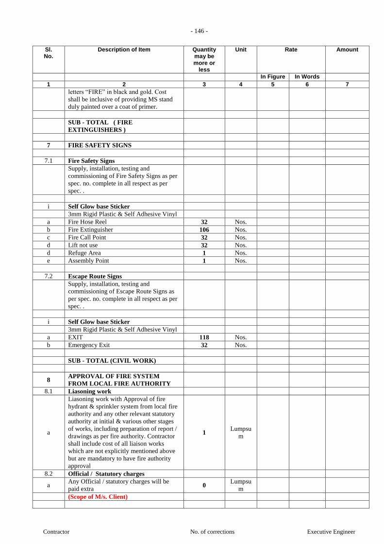
- 146 -
Contractor No. of corrections Executive Engineer
Sl. No.
Description of Item Quantity may be more or
less
Unit Rate Amount
In Figure In Words 1 2 3 4 5 6 7
letters “FIRE” in black and gold. Cost
shall be inclusive of providing MS stand
duly painted over a coat of primer.
SUB - TOTAL ( FIRE
EXTINGUISHERS )
7 FIRE SAFETY SIGNS
7.1 Fire Safety Signs
Supply, installation, testing and
commissioning of Fire Safety Signs as per
spec. no. complete in all respect as per
spec. .
i Self Glow base Sticker
3mm Rigid Plastic & Self Adhesive Vinyl
a Fire Hose Reel 32 Nos.
b Fire Extinguisher 106 Nos.
c Fire Call Point 32 Nos.
d Lift not use 32 Nos.
d Refuge Area 1 Nos.
e Assembly Point 1 Nos.
7.2 Escape Route Signs
Supply, installation, testing and
commissioning of Escape Route Signs as
per spec. no. complete in all respect as per
spec. .
i Self Glow base Sticker
3mm Rigid Plastic & Self Adhesive Vinyl
a EXIT 118 Nos.
b Emergency Exit 32 Nos.
SUB - TOTAL (CIVIL WORK)
8 APPROVAL OF FIRE SYSTEM
FROM LOCAL FIRE AUTHORITY
8.1 Liasoning work
a
Liasoning work with Approval of fire
hydrant & sprinkler system from local fire
authority and any other relevant statutory
authority at initial & various other stages
of works, including preparation of report /
drawings as per fire authority. Contractor
shall include cost of all liaison works
which are not explicitly mentioned above
but are mandatory to have fire authority
approval
1 Lumpsu
m
8.2 Official / Statutory charges
a Any Official / statutory charges will be
paid extra 0
Lumpsu
m
(Scope of M/s. Client)

- 147 -
Contractor No. of corrections Executive Engineer
Sl. No.
Description of Item Quantity may be more or
less
Unit Rate Amount
In Figure In Words 1 2 3 4 5 6 7
SUB - TOTAL (APPROVAL OF FIRE
SYSTEM FROM LOCAL FIRE
AUTHORITY)
H V A C
HIGH SIDE
1.0 Supply & Installation of VRV or VRF
OODU / IDU and Other Accessories
Note: Anti corrosive resistance pant on all
Out Door Unit and In Door Unit with also
100% on Copper pipe.
1.1 VRV or VRF Out-Door Units
Supply & Installtionof VRV or VRF Out-
door units System with R410A Refrigerant
Note: ( The Prices of ODU is including
with REFNET Joints for Out door Units )
a 10 HP No. 3
1.2 VRV or VRF of In-Door Units
Supply & Installation VRV or VRF In-
Door Units System with R410A
Refrigerant
1.3 Ductables Ceiling concealed type
a 10.0 HP No. 3
1.4 Remote control
Supply & Installation of Remote control
a Corded Remote control for
(Ductable/FCU)
No. 3
1.5 REFNET Joints
a Supply & Installtion of All REFNET
Joints for IDU only
No. 2
1.6 Centralised Remote Controller system
(CRC)
Supply & Installtion of Centralised
Remote Controller system of VRV system
for all the indoor & outdoor units.
a Only ON/OFF Type Centralised Remote
Controller system
No. 1
SUB - TOTAL (HIGH SIDE)
LOW SIDE
2.0 REFRIGERANT PIPING
Supply, Installation,Testing and
Commissioning of All refrigerant piping
between indoor & outdoor units duly
insulated and covered with Aluminium foil
as per specifications. All piping inside the
room shall be properly supported with
hanger and exposed pi

- 148 -
Contractor No. of corrections Executive Engineer
Sl. No.
Description of Item Quantity may be more or
less
Unit Rate Amount
In Figure In Words 1 2 3 4 5 6 7
b 10 HP No. 3
2.1 Refrigerant Charging
Supply, Installation,Testing and
Commissioning charges along with
Topping-up of Refrigerant
Lot 1
2.2 Trey for Refrigerant Piping Lot 1
Size as per applicable
SUB - TOTAL (REFRIGERANT PIPING)
3.0 FRAME WORK
Supply, fabrication and installation,
Testing and Commissioning of MS base
frame for outdoor units complete with
epoxy painting, vibration isolation pads,
supports, hangers, railing, brackets etc.
Note: For constructions approved by
Architect/ Consultant. Apply 2 coats of
epoxy primer and 2 coats of finish painting
(black paint) as approved by Architect.
Stand to be made as per site conditions.
b 10 HP No. 3
SUB - TOTAL (FRAME WORK)
4.0 DRAIN PIPING
4.1 PVC Drain
Condensate Drain Water piping
constructed out of PVC / HDPE hard
pipes, fitting, accessories, bends, elbows,
tees, flanges, tappings, wall sleeves,
hangers, supports, anchors. The pipes to be
duly insulated with 10 mm Nitrile rubber
insulation .
a 32 mm Dia RMT 50
b 25 mm Dia RMT 10
SUB - TOTAL (DRAIN PIPING )
5.0 SHEET METAL WORK
5.1 GI Duct
Fabrication, supply, installation, testing &
commissioning of Galvanised Iron ( GI
)shall conform IS: 227 – 1977 Sheet
ducting complete with splitter dampers,
turning vanes, access doors, supports etc.
as per drawings and specifications.
Supports for duct
Note : All exposed ventilation duct work
should be painted with 2 coats of epoxy
primer and 2 coats of epoxy paint.All the
supports of the duct will be painted to

- 149 -
Contractor No. of corrections Executive Engineer
Sl. No.
Description of Item Quantity may be more or
less
Unit Rate Amount
In Figure In Words 1 2 3 4 5 6 7
match the ducting. Please note that the
supports for ducting have to be taken from
the ceili
Prefered makes : (Tata, Jindal).
As per Fabrication & Factory L shape
a 20 G Ducting (upto 1500mm upto
2250mm any side)
Sq.Ft. 200
b 22 G Ducting (above 750mm upto
1500mm anyside)
Sq.Ft. 400
c 24 G Ducting (upto 750mm any side) Sq.Ft. 1400
5.2 Continous Linear Grilles
Supply, installation,testing and
commissioning of following sizes of
Aluminium extruded powder coated
continous grilles with 4 side flanges
Note : If required Contractor should blank
off the extra portion of grille without
additional cost and provide deflection of 0
deg to 45 deg without extra cost
a 200mm wide SQFT 1
b 150mm wide SQFT 70
5.3 Fire Dampers
Supply, installation of fire dampers with
control cabling at the unit outlet.
a Fire dampers in supply air duct SQFT 10
5.4 Volume Control Dampers for Duct
Supply, installation, testing and
commissioning of volume control dampers
at Machine outlet and in Branch duct.
(Gear Operated and Low Leakage)
SQFT 10
5.5 Volume Control Dampers for S.A Collar
Supply and Installation of Black MS Box-
Type Volume Control Dampers for
Coller.
SQFT 10
5.6 Canvass Connections
Supply, installation, testing and
commissioning of Flexible double Canvass
Connections for DUCTABLE, FCU &
FAN.
NOS 3
5.7 Sound attenuators
Supply, installation, testing and
commissioning of Sound attenuators
as per the supply air duct sizes shown in
the drawings.
SQFT 10
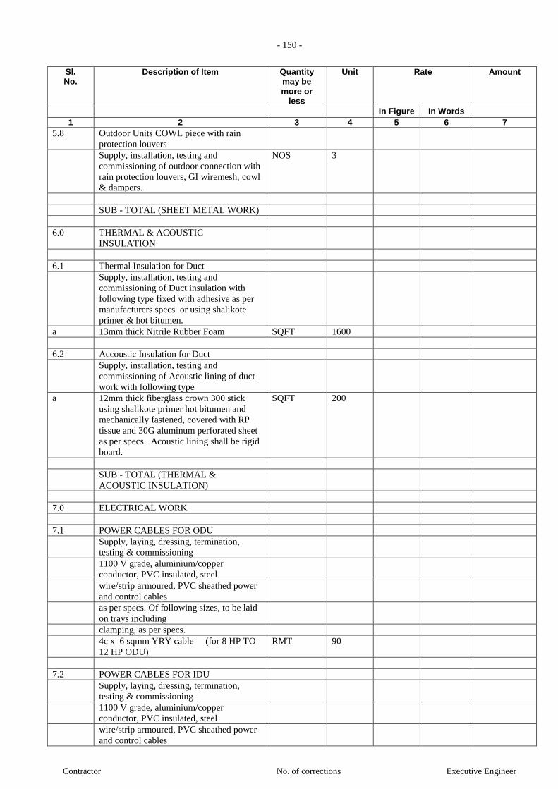
- 150 -
Contractor No. of corrections Executive Engineer
Sl. No.
Description of Item Quantity may be more or
less
Unit Rate Amount
In Figure In Words 1 2 3 4 5 6 7
5.8 Outdoor Units COWL piece with rain
protection louvers
Supply, installation, testing and
commissioning of outdoor connection with
rain protection louvers, GI wiremesh, cowl
& dampers.
NOS 3
SUB - TOTAL (SHEET METAL WORK)
6.0 THERMAL & ACOUSTIC
INSULATION
6.1 Thermal Insulation for Duct
Supply, installation, testing and
commissioning of Duct insulation with
following type fixed with adhesive as per
manufacturers specs or using shalikote
primer & hot bitumen.
a 13mm thick Nitrile Rubber Foam SQFT 1600
6.2 Accoustic Insulation for Duct
Supply, installation, testing and
commissioning of Acoustic lining of duct
work with following type
a 12mm thick fiberglass crown 300 stick
using shalikote primer hot bitumen and
mechanically fastened, covered with RP
tissue and 30G aluminum perforated sheet
as per specs. Acoustic lining shall be rigid
board.
SQFT 200
SUB - TOTAL (THERMAL &
ACOUSTIC INSULATION)
7.0 ELECTRICAL WORK
7.1 POWER CABLES FOR ODU
Supply, laying, dressing, termination,
testing & commissioning
1100 V grade, aluminium/copper
conductor, PVC insulated, steel
wire/strip armoured, PVC sheathed power
and control cables
as per specs. Of following sizes, to be laid
on trays including
clamping, as per specs.
4c x 6 sqmm YRY cable (for 8 HP TO
12 HP ODU)
RMT 90
7.2 POWER CABLES FOR IDU
Supply, laying, dressing, termination,
testing & commissioning
1100 V grade, aluminium/copper
conductor, PVC insulated, steel
wire/strip armoured, PVC sheathed power
and control cables

- 151 -
Contractor No. of corrections Executive Engineer
Sl. No.
Description of Item Quantity may be more or
less
Unit Rate Amount
In Figure In Words 1 2 3 4 5 6 7
as per specs. Of following sizes, to be laid
on trays including
clamping, as per specs.
4c x 1.5 sqmm YRY cable (for 1 HP
TO 10 HP IDU)
RMT 120
7.3 CONTROL CABLES FOR BETWEEN
ODU AND IDU
Supply & Installation of All control cables
between indoor and outdoor unit and
between ODU & ODU laid in PVC pipe
and clamped .
2c x 1.5 sqmm YRY cable LOT 1
7.4 CONTROL CABLES FOR BETWEEN
IDU AND THEIR REMOTE
Supply & Installation of All control cables
between indoor and their Remote laid in
PVC pipe and clamped .
2c x 1.5 sqmm YRY cable LOT 1
SUB - TOTAL (ELECTRICAL WORK)
VENTILATION SYSTEM
1.0 EXHAUST FANS
1.1 Axial Exhaust Fan: (AS SMOKE
EXTRACTION FAN)
Supply, installation,testing and
commissioning of axial exhaust air
fan are
required to be in compliance with the
requirements of Class B
performance, as defined in clause 9
of BS 7346:Part 2:1990. This
requires the fan to be subjected to
a rated temperature of 250C for a
rated duration of 120 minutes.
with M.S floating foundations,
motors, and all other accessories
whether specifically mentioned or
not.
Note: Fan motor rpm not to exceed
600.
Preferred Makes :
Kruger/Flaktwood/Airovent
a Air Qty : 10000 CFM
(For BASEMENT 2&3)

- 152 -
Contractor No. of corrections Executive Engineer
Sl. No.
Description of Item Quantity may be more or
less
Unit Rate Amount
In Figure In Words 1 2 3 4 5 6 7
Static Pressure : 20 mm Wg
Motor : 10 kW
Mounting : Ceiling
Suspended NOS
8
b Air Qty : 11000 CFM
(For BASEMENT 1)
Static Pressure : 20 mm Wg
Motor : 10 kW
Mounting : Ceiling
Suspended NOS
4
c Air Qty : 8500 CFM
(For PUMP ROOM)
Static Pressure : 15 mm Wg
Motor : 4 kW
Mounting : Ceiling
Suspended NOS
1
d Air Qty : 13500 CFM
(For common Toilet)
Static Pressure : 15 mm Wg
Motor : 6 kW
Mounting : Ceiling
Suspended NOS
4
1.2 Propeller Fan:
The propeller fans for exhaust and
fresh air shall be complete with
speed control, louver shutter, rain
protection louver, bird screen. Fans
to be ring mountedon suitable frame
provided by AC Contractor. Power
will be provided 5 ft away from fan
and necessary wiring with plug will be
provided by AC contractor.
a 12" dia
NOS
2
1.3 In line exhaust fan
The inline fans shall be complete
with Centrifugal fan, unit casing
access door, electrical connections
canopy fan shall be suitable for
outdoor installation A/C contractor
to include all accessories for
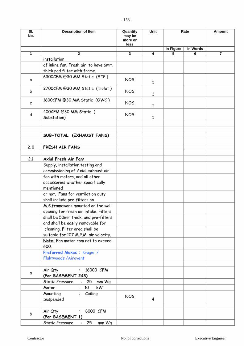
- 153 -
Contractor No. of corrections Executive Engineer
Sl. No.
Description of Item Quantity may be more or
less
Unit Rate Amount
In Figure In Words 1 2 3 4 5 6 7
installation
of inline fan. Fresh air to have 6mm
thick pad filter with frame.
a 6300CFM @30 MM Static (STP )
NOS
1
b 2700CFM @30 MM Static (Tiolet )
NOS
1
c 1600CFM @30 MM Static (OWC )
NOS
1
d 400CFM @30 MM Static (
Substation) NOS
1
SUB-TOTAL (EXHAUST FANS)
2.0 FRESH AIR FANS
2.1 Axial Fresh Air Fan:
Supply, installation,testing and
commissioning of Axial exhaust air
fan with motors, and all other
accessories whether specifically
mentioned
or not. Fans for ventilation duty
shall include pre-filters on
M.S.framework mounted on the wall
opening for fresh air intake. Filters
shall be 50mm thick, and pre-filters
and shall be easily removable for
cleaning. Filter area shall be
suitable for 107 M.P.M. air velocity.
Note: Fan motor rpm not to exceed
600.
Preferred Makes : Kruger /
Flaktwoods /Airovent
a Air Qty : 16000 CFM
(For BASEMENT 2&3)
Static Pressure : 25 mm Wg
Motor : 10 kW
Mounting : Ceiling
Suspended NOS
4
b Air Qty : 8000 CFM
(For BASEMENT 1)
Static Pressure : 25 mm Wg
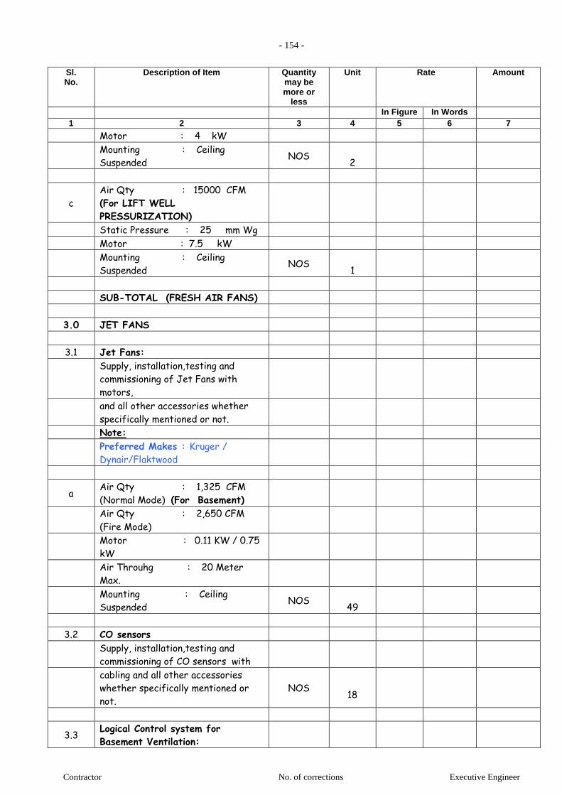
- 154 -
Contractor No. of corrections Executive Engineer
Sl. No.
Description of Item Quantity may be more or
less
Unit Rate Amount
In Figure In Words 1 2 3 4 5 6 7
Motor : 4 kW
Mounting : Ceiling
Suspended NOS
2
c Air Qty : 15000 CFM
(For LIFT WELL
PRESSURIZATION)
Static Pressure : 25 mm Wg
Motor : 7.5 kW
Mounting : Ceiling
Suspended NOS
1
SUB-TOTAL (FRESH AIR FANS)
3.0 JET FANS
3.1 Jet Fans:
Supply, installation,testing and
commissioning of Jet Fans with
motors,
and all other accessories whether
specifically mentioned or not.
Note:
Preferred Makes : Kruger /
Dynair/Flaktwood
a Air Qty : 1,325 CFM
(Normal Mode) (For Basement)
Air Qty : 2,650 CFM
(Fire Mode)
Motor : 0.11 KW / 0.75
kW
Air Throuhg : 20 Meter
Max.
Mounting : Ceiling
Suspended NOS
49
3.2 CO sensors
Supply, installation,testing and
commissioning of CO sensors with
cabling and all other accessories
whether specifically mentioned or
not. NOS
18
3.3 Logical Control system for
Basement Ventilation:
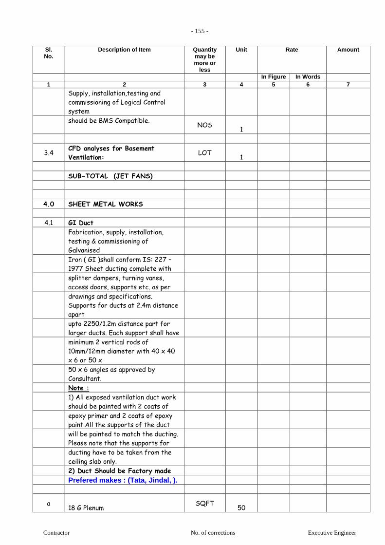
- 155 -
Contractor No. of corrections Executive Engineer
Sl. No.
Description of Item Quantity may be more or
less
Unit Rate Amount
In Figure In Words 1 2 3 4 5 6 7
Supply, installation,testing and
commissioning of Logical Control
system
should be BMS Compatible.
NOS
1
3.4 CFD analyses for Basement
Ventilation: LOT
1
SUB-TOTAL (JET FANS)
4.0 SHEET METAL WORKS
4.1 GI Duct
Fabrication, supply, installation,
testing & commissioning of
Galvanised
Iron ( GI )shall conform IS: 227 –
1977 Sheet ducting complete with
splitter dampers, turning vanes,
access doors, supports etc. as per
drawings and specifications.
Supports for ducts at 2.4m distance
apart
upto 2250/1.2m distance part for
larger ducts. Each support shall have
minimum 2 vertical rods of
10mm/12mm diameter with 40 x 40
x 6 or 50 x
50 x 6 angles as approved by
Consultant.
Note :
1) All exposed ventilation duct work
should be painted with 2 coats of
epoxy primer and 2 coats of epoxy
paint.All the supports of the duct
will be painted to match the ducting.
Please note that the supports for
ducting have to be taken from the
ceiling slab only.
2) Duct Should be Factory made
Prefered makes : (Tata, Jindal, ).
a 18 G Plenum
SQFT
50
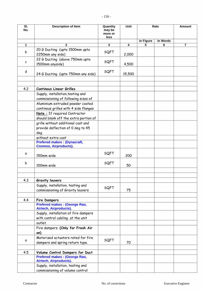
- 156 -
Contractor No. of corrections Executive Engineer
Sl. No.
Description of Item Quantity may be more or
less
Unit Rate Amount
In Figure In Words 1 2 3 4 5 6 7
b 20 G Ducting (upto 1500mm upto
2250mm any side) SQFT
2,000
c 22 G Ducting (above 750mm upto
1500mm anyside) SQFT
4,500
d 24 G Ducting (upto 750mm any side)
SQFT
15,500
4.2 Continous Linear Grilles
Supply, installation,testing and
commissioning of following sizes of
Aluminium extruded powder coated
continous grilles with 4 side flanges
Note : If required Contractor
should blank off the extra portion of
grille without additional cost and
provide deflection of 0 deg to 45
deg
without extra cost
Prefered makes : (Dynacraft, Cosmos, Airproducts).
a 150mm wide
SQFT
200
b 100mm wide
SQFT
50
4.3 Gravity louvers
Supply, installation, testing and
commissioning of Gravity louvers SQFT
75
4.4 Fire Dampers
Prefered makes : (George Rao, Airtech, Airproducts).
Supply, installation of fire dampers
with control cabling at the unit
outlet.
Fire dampers (Only for Fresh Air
an)
a Motorized actuators rated for fire
dampers and spring return type. SQFT
70
4.5 Volume Control Dampers for Duct
Prefered makes : (George Rao, Airtech, Airproducts).
Supply, installation, testing and
commissioning of volume control
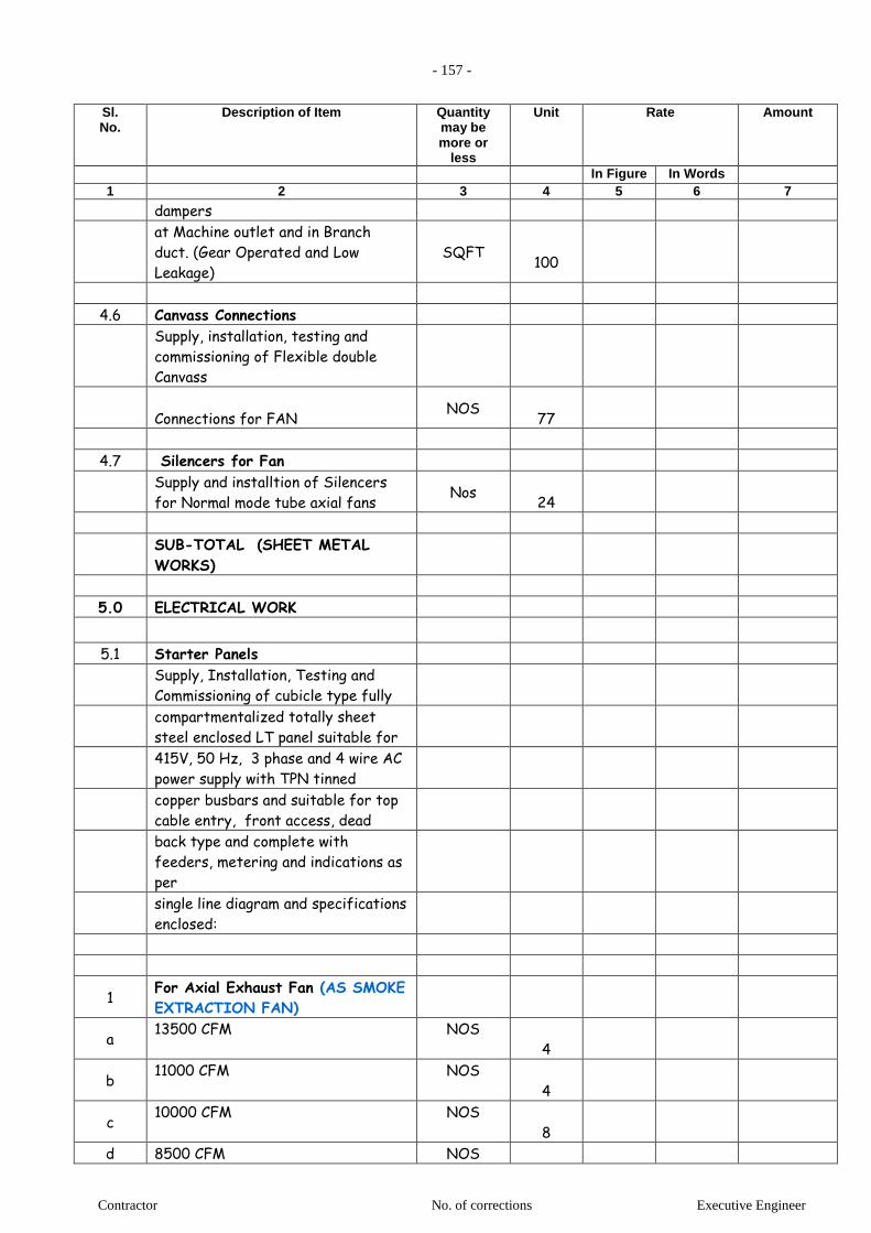
- 157 -
Contractor No. of corrections Executive Engineer
Sl. No.
Description of Item Quantity may be more or
less
Unit Rate Amount
In Figure In Words 1 2 3 4 5 6 7
dampers
at Machine outlet and in Branch
duct. (Gear Operated and Low
Leakage) SQFT
100
4.6 Canvass Connections
Supply, installation, testing and
commissioning of Flexible double
Canvass
Connections for FAN
NOS
77
4.7 Silencers for Fan
Supply and installtion of Silencers
for Normal mode tube axial fans Nos
24
SUB-TOTAL (SHEET METAL
WORKS)
5.0 ELECTRICAL WORK
5.1 Starter Panels
Supply, Installation, Testing and
Commissioning of cubicle type fully
compartmentalized totally sheet
steel enclosed LT panel suitable for
415V, 50 Hz, 3 phase and 4 wire AC
power supply with TPN tinned
copper busbars and suitable for top
cable entry, front access, dead
back type and complete with
feeders, metering and indications as
per
single line diagram and specifications
enclosed:
1 For Axial Exhaust Fan (AS SMOKE
EXTRACTION FAN)
a 13500 CFM NOS
4
b 11000 CFM NOS
4
c 10000 CFM NOS
8
d 8500 CFM NOS
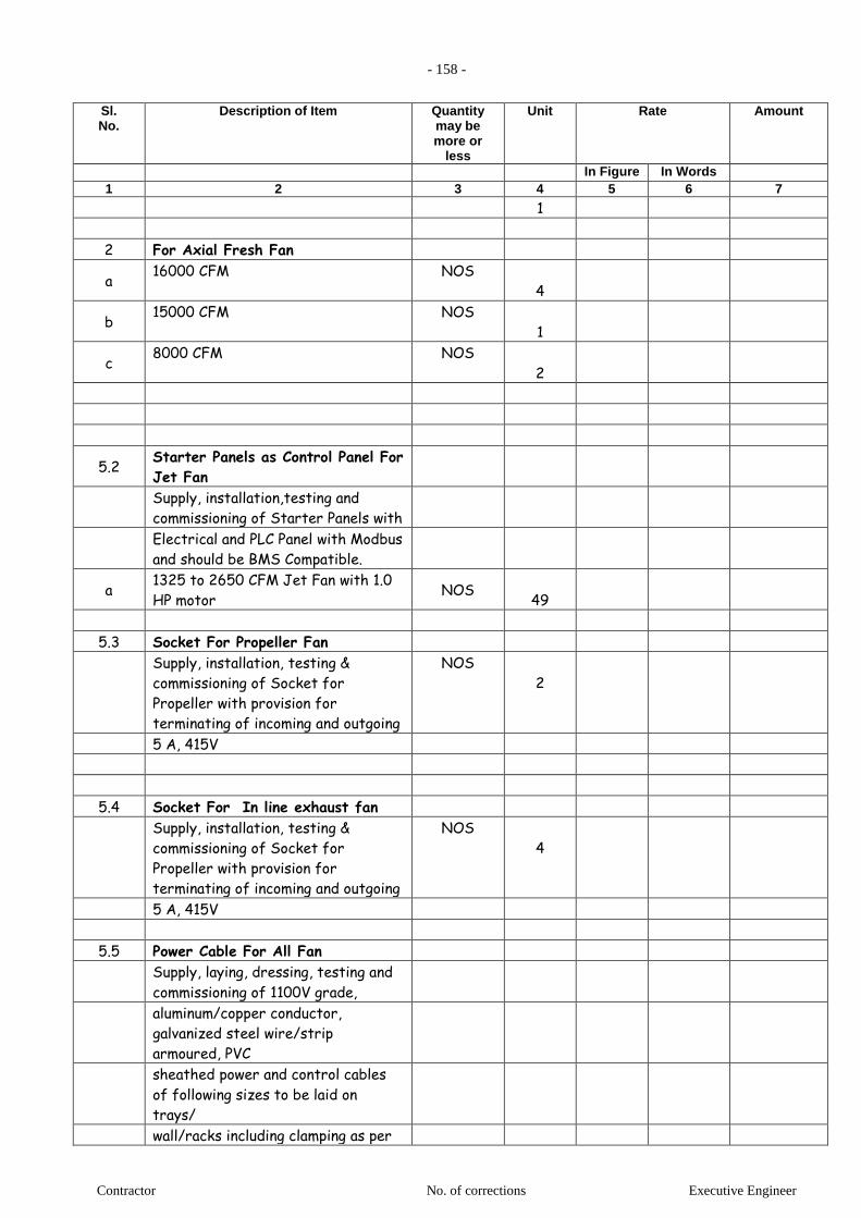
- 158 -
Contractor No. of corrections Executive Engineer
Sl. No.
Description of Item Quantity may be more or
less
Unit Rate Amount
In Figure In Words 1 2 3 4 5 6 7
1
2 For Axial Fresh Fan
a 16000 CFM NOS
4
b 15000 CFM NOS
1
c 8000 CFM NOS
2
5.2 Starter Panels as Control Panel For
Jet Fan
Supply, installation,testing and
commissioning of Starter Panels with
Electrical and PLC Panel with Modbus
and should be BMS Compatible.
a 1325 to 2650 CFM Jet Fan with 1.0
HP motor NOS
49
5.3 Socket For Propeller Fan
Supply, installation, testing &
commissioning of Socket for
Propeller with provision for
terminating of incoming and outgoing
NOS
2
5 A, 415V
5.4 Socket For In line exhaust fan
Supply, installation, testing &
commissioning of Socket for
Propeller with provision for
terminating of incoming and outgoing
NOS
4
5 A, 415V
5.5 Power Cable For All Fan
Supply, laying, dressing, testing and
commissioning of 1100V grade,
aluminum/copper conductor,
galvanized steel wire/strip
armoured, PVC
sheathed power and control cables
of following sizes to be laid on
trays/
wall/racks including clamping as per
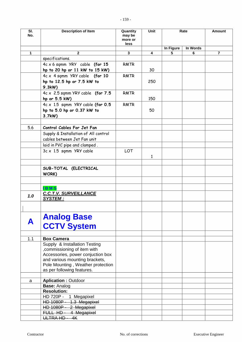
- 159 -
Contractor No. of corrections Executive Engineer
Sl. No.
Description of Item Quantity may be more or
less
Unit Rate Amount
In Figure In Words 1 2 3 4 5 6 7
specifications.
4c x 6 sqmm YRY cable (for 15
hp to 20 hp or 11 kW to 15 kW) RMTR
30
4c x 4 sqmm YRY cable (for 10
hp to 12.5 hp or 7.5 kW to
9.3kW)
RMTR
250
4c x 2.5 sqmm YRY cable (for 7.5
hp or 5.5 kW) RMTR
150
4c x 1.5 sqmm YRY cable (for 0.5
hp to 5.0 hp or 0.37 kW to
3.7kW)
RMTR
50
5.6 Control Cables For Jet Fan
Supply & Installation of All control
cables between Jet Fan unit
laid in PVC pipe and clamped .
3c x 1.5 sqmm YRY cable LOT
1
SUB-TOTAL (ELECTRICAL
WORK)
I B M S
1.0 C.C.T.V. SURVEILLANCE SYSTEM :
A Analog Base CCTV System
1.1 Box Camera
Supply & Installation Testing ,commissioning of item with Accessories, power conjuction box and various mounting brackets, Pole Mounting , Weather protection as per following features.
a Aplication : Outdoor
Base: Analog
Resolution:
HD 720P - 1 Megapixel
HD 1080P - 1.3 Megapixel
HD 1080P - 2 Megapixel
FULL HD - 4 Megapixel
ULTRA HD - 4K

- 160 -
Contractor No. of corrections Executive Engineer
Sl. No.
Description of Item Quantity may be more or
less
Unit Rate Amount
In Figure In Words 1 2 3 4 5 6 7
Lens : Varifocal / Fixed
With: POE (for no need of power cable)
With: Infrared IR (Day/ Night Camera)
With: Analytical software control for intrusion alarm
With: Color 30 Nos
1.2 Dome Cameras
Supply & Installation Testing ,commissioning of item with Accessories, power conjuction box and various mounting brackets, Pole Mounting , Weather protection as per following features.
b Aplication : Indoor
Base: Analog
Resolution:
HD 720P - 1 Megapixel
HD 1080P - 1.3 Megapixel
HD 1080P - 2 Megapixel
FULL HD - 4 Megapixel
ULTRA HD - 4K
Lens : Varifocal / Fixed
With: POE (for no need of power cable)
With: Infrared IR (Day/ Night Camera)
With: Analytical software control for intrusion alarm
With: Color 80 Nos
1.3 DVR (Digital Video Recorder )
Supply & Installation Testing ,commissioning of item with Accessories, as per following features.
Recoding: CIF, 2CIF, 4CIF, Up to 5 Megapixels
1 Sata port support upto 1 TB HDD,
lanport for LAN/WAN connectivty.
Mobile device suppor: No
Remote alarm notification: No
Remote alarm notification: No
Network function for remote viewing: No
Analog video Input:

- 161 -
Contractor No. of corrections Executive Engineer
Sl. No.
Description of Item Quantity may be more or
less
Unit Rate Amount
In Figure In Words 1 2 3 4 5 6 7
8- Ch 0 Nos
16- Ch 0 Nos
32- Ch 4 Nos
1.4 Hard Disk
Supply & Installation Testing ,commissioning of item with Accessories, as per following features.
Hard Disk: (For 45 Days) 2 Nos
1.5 C.C.T.V. System Softwares. 0 Set
3.8 Monitors
a 21" LCD 0 Set
b 32" LCD 8 Set
1.6 PC 0 Set
1.7 Equipment Rack (In Client Scope)
Equipment Rack with with proper ventilated and openable doors from all sides, with casters and with cooling fans as above complete with necessary mounting hardware & accesories.
4 U 0 Nos
6 U 0 Nos
8 U 0 Nos
12 U 0 Nos
16 U 2 Nos
32 U 0 Nos
1.8 Cables
Option-1
a Video Transfer Cable
RG 6
i RG 6 Coax Cable 0 RMT
ii RG 6 Coax Cable 0 Lot
b Power Cable
SITC Stranded Copper conductor,Type A ST1 PVC insulated,Armoured FRLS Cable 650 V as per IS 1554, with GI saddle spacers every 0.3 mtr with Single compression Cable

- 162 -
Contractor No. of corrections Executive Engineer
Sl. No.
Description of Item Quantity may be more or
less
Unit Rate Amount
In Figure In Words 1 2 3 4 5 6 7
Glands,ABS Junction Boxes (wherever required ), terminals,Ferruling complete.
with 19mm FRLS PVC Conduit
a 2c x1.0 mm2 1500 RMT
b 2c x1.0 mm2 0 Lot
0 Lot
Option-2
a Video Transfer Cable + Power Cable
Cat 6
i Cat - 6 /4 Pair cables (UTP). 1,500 RMT
ii Cat - 6 /4 Pair cables (UTP). 0 Lot
0
1.9 Miscellaneous components, accessories,
connectors, jacks etc. not indicated here.
but required for a complete CCTV Surveillance,
Video Recording and Remote Monitoring Systems.
0 Lumpsum
(Tenderer shall list out such items with quantities)
1.0 Total - C.C.T.V. SURVEILLANCE -
1.0 SECURITY SYSTEM:
1.1 Vehicle Access Control:
a AUTO SLIDING GATES
Supply & Installation Testing ,commissioning of item with Accessories as per following features.
i) Type of Gate: Motorised Telescopic Sliding Gates
Gates Opening; 8 m
Gates weighing; 1200 kg
With Features:
Manual operation in case of power failure
Incomplete gate closing operation warning light
Obstacle detection causes the gate movement to stop if an obstacle is

- 163 -
Contractor No. of corrections Executive Engineer
Sl. No.
Description of Item Quantity may be more or
less
Unit Rate Amount
In Figure In Words 1 2 3 4 5 6 7
detected
with Remote Controls 2 Nos
Note; Door Design by Architect, Door construct not in SECURITY SYSTEM Vendor scope.
b AUTO SWING GATES
Supply & Installation Testing ,commissioning of item with Accessories as per following features.
Type of Gate: Motorised Actuators
Gates Opening; 8 m
Gates weighing; 1500 kg
With Features:
Manual operation in case of power failure
Incomplete gate closing operation warning light
Obstacle detection causes the gate movement to stop if an obstacle is detected
with Remote Controls 2 Nos
Note; Door Design by Architect, Door construct not in SECURITY SYSTEM Vendor scope.
c
BOOM BARRIERS
Supply & Installation Testing ,commissioning of item with Accessories as per following features.
Boom length : 2 up to 8.4 m
Opening / Closing times max. : 4.0 sec
Hydraulic System / Electro : Mechanical
Protection Class : IP54
Manual override in case of power failure
Adjustable: opening /closing times
Without: Boom skirt (For additional barrage below the barrier boom when the barrier is closed)
Without: Articulated Boom (For low height)
With: LED lighting (For visibility of the barrier boom)
With: Obstacle detection causes theBoom movement to stop if an
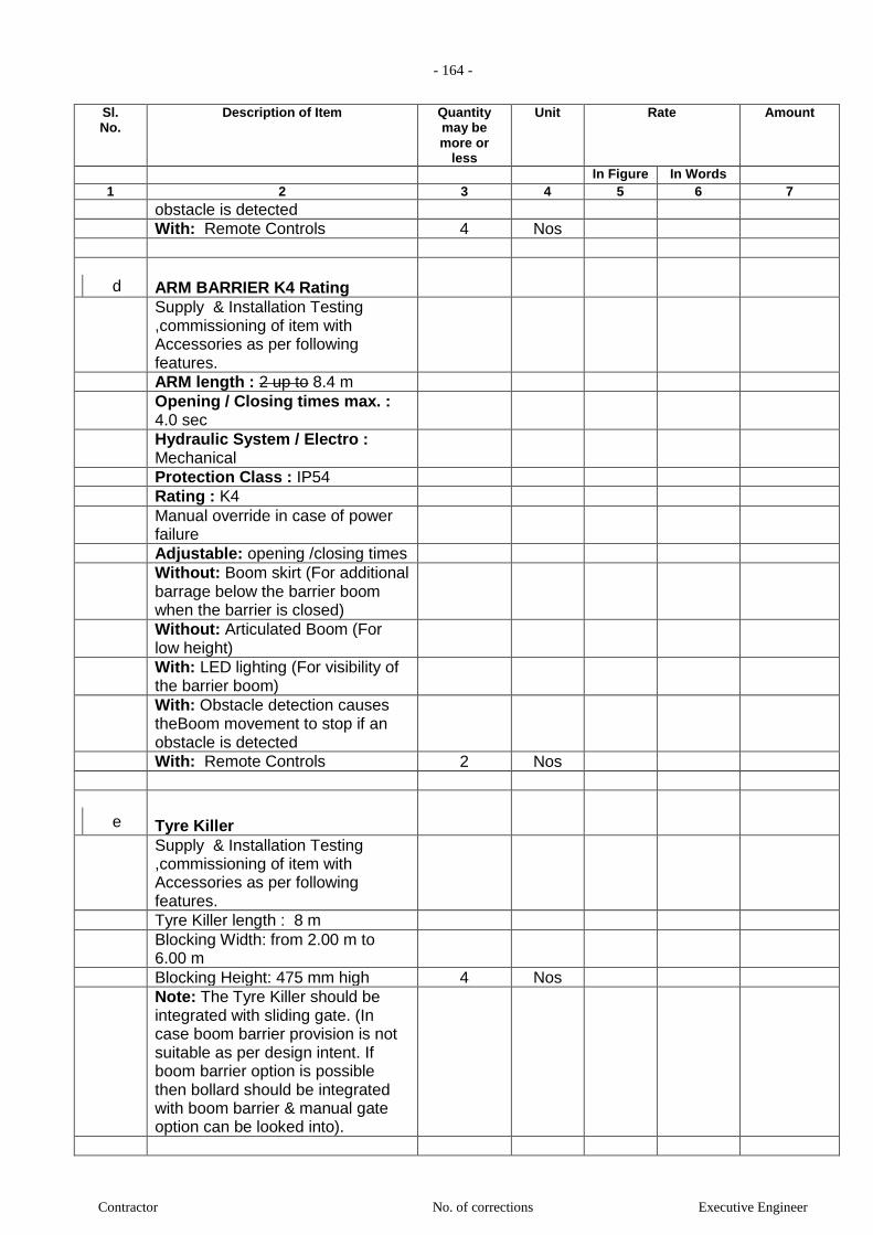
- 164 -
Contractor No. of corrections Executive Engineer
Sl. No.
Description of Item Quantity may be more or
less
Unit Rate Amount
In Figure In Words 1 2 3 4 5 6 7
obstacle is detected
With: Remote Controls 4 Nos
d
ARM BARRIER K4 Rating
Supply & Installation Testing ,commissioning of item with Accessories as per following features.
ARM length : 2 up to 8.4 m
Opening / Closing times max. : 4.0 sec
Hydraulic System / Electro : Mechanical
Protection Class : IP54
Rating : K4
Manual override in case of power failure
Adjustable: opening /closing times
Without: Boom skirt (For additional barrage below the barrier boom when the barrier is closed)
Without: Articulated Boom (For low height)
With: LED lighting (For visibility of the barrier boom)
With: Obstacle detection causes theBoom movement to stop if an obstacle is detected
With: Remote Controls 2 Nos
e
Tyre Killer
Supply & Installation Testing ,commissioning of item with Accessories as per following features.
Tyre Killer length : 8 m
Blocking Width: from 2.00 m to 6.00 m
Blocking Height: 475 mm high 4 Nos
Note: The Tyre Killer should be integrated with sliding gate. (In case boom barrier provision is not suitable as per design intent. If boom barrier option is possible then bollard should be integrated with boom barrier & manual gate option can be looked into).
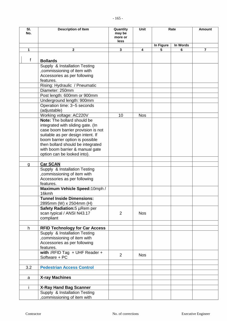
- 165 -
Contractor No. of corrections Executive Engineer
Sl. No.
Description of Item Quantity may be more or
less
Unit Rate Amount
In Figure In Words 1 2 3 4 5 6 7
f
Bollards
Supply & Installation Testing ,commissioning of item with Accessories as per following features.
Rising: Hydraulic / Pneumatic
Diameter: 250mm
Post length: 600mm or 900mm
Underground length: 900mm
Operation time: 3~5 seconds (adjustable)
Working voltage: AC220V 10 Nos
Note: The bollard should be integrated with sliding gate. (In case boom barrier provision is not suitable as per design intent. If boom barrier option is possible then bollard should be integrated with boom barrier & manual gate option can be looked into).
g Car SCAN
Supply & Installation Testing ,commissioning of item with Accessories as per following features.
Maximum Vehicle Speed:10mph / 16kmh
Tunnel Inside Dimensions: 2895mm (W) x 2504mm (H)
Safety Radiation:5 µRem per scan typical / ANSI N43.17 compliant
2 Nos
h RFID Technology for Car Access
Supply & Installation Testing ,commissioning of item with Accessories as per following features.
with :RFID Tag + UHF Reader + Software + PC
2 Nos
3.2 Pedestrian Access Control
a X-ray Machines
i X-Ray Hand Bag Scanner
Supply & Installation Testing ,commissioning of item with
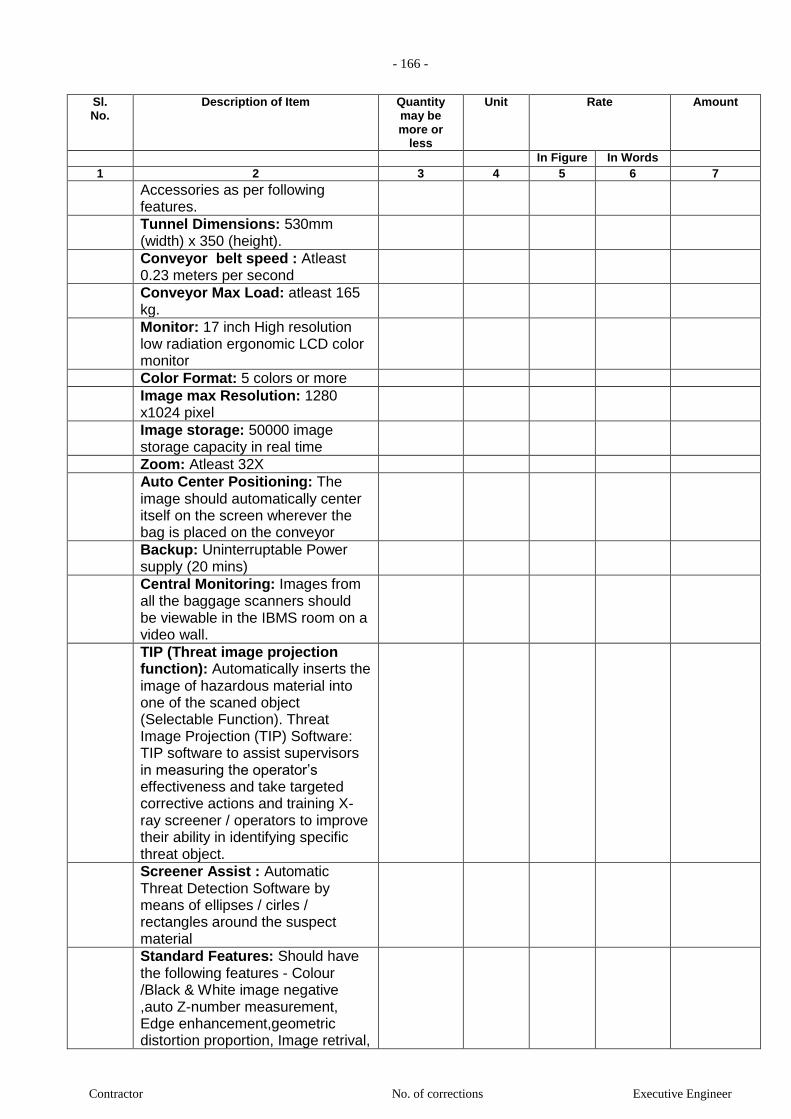
- 166 -
Contractor No. of corrections Executive Engineer
Sl. No.
Description of Item Quantity may be more or
less
Unit Rate Amount
In Figure In Words 1 2 3 4 5 6 7
Accessories as per following features.
Tunnel Dimensions: 530mm (width) x 350 (height).
Conveyor belt speed : Atleast 0.23 meters per second
Conveyor Max Load: atleast 165 kg.
Monitor: 17 inch High resolution low radiation ergonomic LCD color monitor
Color Format: 5 colors or more
Image max Resolution: 1280 x1024 pixel
Image storage: 50000 image storage capacity in real time
Zoom: Atleast 32X
Auto Center Positioning: The image should automatically center itself on the screen wherever the bag is placed on the conveyor
Backup: Uninterruptable Power supply (20 mins)
Central Monitoring: Images from all the baggage scanners should be viewable in the IBMS room on a video wall.
TIP (Threat image projection function): Automatically inserts the image of hazardous material into one of the scaned object (Selectable Function). Threat Image Projection (TIP) Software: TIP software to assist supervisors in measuring the operator’s effectiveness and take targeted corrective actions and training X-ray screener / operators to improve their ability in identifying specific threat object.
Screener Assist : Automatic Threat Detection Software by means of ellipses / cirles / rectangles around the suspect material
Standard Features: Should have the following features - Colour /Black & White image negative ,auto Z-number measurement, Edge enhancement,geometric distortion proportion, Image retrival,

- 167 -
Contractor No. of corrections Executive Engineer
Sl. No.
Description of Item Quantity may be more or
less
Unit Rate Amount
In Figure In Words 1 2 3 4 5 6 7
image review, pseudo color, reverse monochrome, organic and inorganic imaging
Certification: AERB 1 Nos
ii X-Ray Baggage Scanner
Supply & Installation Testing ,commissioning of item with Accessories as per following features.
Tunnel Dimensions: 1010mm (width) x 1010 (height).
Conveyor belt speed : Atleast 0.23 meters per second
Conveyor Max Load: atleast 200 kg.
Monitor: 17 inch High resolution low radiation ergonomic LCD color monitor
Color Format: 5 colors or more
Image max Resolution: 1280 x1024 pixel
Image storage: 50000 image storage capacity in real time
Zoom: Atleast 32X
Auto Center Positioning: The image should automatically center itself on the screen wherever the bag is placed on the conveyor
Backup: Uninterruptable Power supply (20 mins)
Central Monitoring: Images from all the baggage scanners should be viewable in the IBMS room on a video wall.
TIP (Threat image projection function): Automatically inserts the image of hazardous material into one of the scaned object (Selectable Function). Threat Image Projection (TIP) Software: TIP software to assist supervisors in measuring the operator’s effectiveness and take targeted corrective actions and training X-ray screener / operators to improve their ability in identifying specific threat object.
Screener Assist : Automatic Threat Detection Software by means of ellipses / cirles /
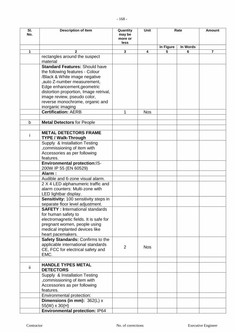
- 168 -
Contractor No. of corrections Executive Engineer
Sl. No.
Description of Item Quantity may be more or
less
Unit Rate Amount
In Figure In Words 1 2 3 4 5 6 7
rectangles around the suspect material
Standard Features: Should have the following features - Colour /Black & White image negative ,auto Z-number measurement, Edge enhancement,geometric distortion proportion, Image retrival, image review, pseudo color, reverse monochrome, organic and inorganic imaging
Certification: AERB 1 Nos
b Metal Detectors for People
i METAL DETECTORS FRAME TYPE / Walk-Through
Supply & Installation Testing ,commissioning of item with Accessories as per following features.
Environmental protection:IS-200W IP 55 (EN 60529)
Alarm :
Audible and 6-zone visual alarm.
2 X 4 LED alphanumeric traffic and alarm counters: Multi-zone with LED lightbar display.
Sensitivity: 100 sensitivity steps in separate floor level adjustment.
SAFETY : International standards for human safety to electromagnetic fields. It is safe for pregnant women, people using medical implanted devices like heart pacemakers.
Safety Standards: Confirms to the applicable international standards CE, FCC for electrical safety and EMC.
2 Nos
ii HANDLE TYPES METAL DETECTORS
Supply & Installation Testing ,commissioning of item with Accessories as per following features.
Environmental protection:
Dimensions (in mm): 362(L) x 55(W) x 30(H)
Environmental protection: IP64

- 169 -
Contractor No. of corrections Executive Engineer
Sl. No.
Description of Item Quantity may be more or
less
Unit Rate Amount
In Figure In Words 1 2 3 4 5 6 7
No risk to persons with pacemakers: Yes
Non-interference to magnetic media: Yes
Battery: 9 volt block battery can be either replaceable 9 Volt 550mA hours or optional rechargeable NiCad 180mA hours.
Tests & approvals: EEC EN5008-1 Table 1:1:1.
4 Nos
3.0 Total -
2.0 Access Control System:
Make : HID / Siemens / VIRDI / Honeywell , Lenel , Cardax, DDS, ZICOM, G4S
2.1 Readers
a Card readers
Supply, installation, testing & commissioning of card readers as per specification suitable for mounting on metal surface/metal frames or wooden frames wall or as required based on site conditions including all accessories
External control: audio/visual indication and internal LED and buzzer
Type: HID Proximity / HID Smart card (Mifare) / HID i-Class
Readers Read Range: 3" 0 Nos
b Card + Pin readers
Supply, installation, testing & commissioning of card readers as per specification suitable for mounting on metal surface/metal frames or wooden frames wall or as required based on site conditions including all accessories
External control: audio/visual indication and internal LED and buzzer
Type: HID Proximity / HID Smart card (Mifare) / HID i-Class
Readers Read Range: 3" 0 Nos
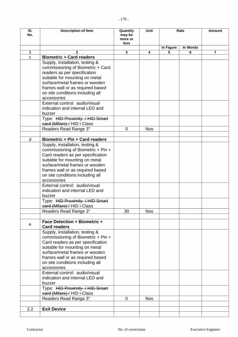
- 170 -
Contractor No. of corrections Executive Engineer
Sl. No.
Description of Item Quantity may be more or
less
Unit Rate Amount
In Figure In Words 1 2 3 4 5 6 7
c Biometric + Card readers
Supply, installation, testing & commissioning of Biometric + Card readers as per specification suitable for mounting on metal surface/metal frames or wooden frames wall or as required based on site conditions including all accessories
External control: audio/visual indication and internal LED and buzzer
Type: HID Proximity / HID Smart card (Mifare) / HID i-Class
Readers Read Range 3" 0 Nos
d Biometric + Pin + Card readers
Supply, installation, testing & commissioning of Biometric + Pin + Card readers as per specification suitable for mounting on metal surface/metal frames or wooden frames wall or as required based on site conditions including all accessories
External control: audio/visual indication and internal LED and buzzer
Type: HID Proximity / HID Smart card (Mifare) / HID i-Class
Readers Read Range 3" 30 Nos
e Face Detection + Biometric + Card readers
Supply, installation, testing & commissioning of Biometric + Pin + Card readers as per specification suitable for mounting on metal surface/metal frames or wooden frames wall or as required based on site conditions including all accessories
External control: audio/visual indication and internal LED and buzzer
Type: HID Proximity / HID Smart card (Mifare) / HID i-Class
Readers Read Range 3" 0 Nos
2.2 Exit Device

- 171 -
Contractor No. of corrections Executive Engineer
Sl. No.
Description of Item Quantity may be more or
less
Unit Rate Amount
In Figure In Words 1 2 3 4 5 6 7
a.i) Panic Bar
Supply installation, testing, commissioning of Panic Bar for fire Escape Door with local alarm
0 Nos
b.ii) Door Ajar Sensor /Buzzer.
Supply installation, testing, commissioning of Door Ajar Buzzer.
0 Nos
c SS Push Button for Exit.
Supply , installation, testing and commissioning of SS Push Button for Exit.
30 Nos
d Emergency Break Glass Units.
Supply installation, testing, commissioning of Green ABS plastic Emergency Break Glass Units.
30 Nos
2.3 Door Lock
i Electromagnetic Lock
Supply, installation, testing and commissioning of electromagnetic Lock (fail safe type) of 600lb holding force for the following type doors :
a Double leaf Door 30 Nos
b Single leaf Door Nos
ii Electromagnetic Lock / Door Strike
Supply installation, testing, commissioning of Magnetic Contact
60 Nos
2.4 Smart Cards
5
Supply of ISO Thickness, Mifare 2K Smart Cards with the possibility of printing the company details on its facia using sublimation method.
Type: HID Proximity / HID Smart card (Mifare) / HID i-Class
2000 Nos
2.5 Controller

- 172 -
Contractor No. of corrections Executive Engineer
Sl. No.
Description of Item Quantity may be more or
less
Unit Rate Amount
In Figure In Words 1 2 3 4 5 6 7
i Reader / Door Controller
Supply installation, Testing & Commissioning of 2/4 Reader Microprocessor based intelligent Access door controller with TCP/IP connectivity and required accessories, power supply unit with Battery Charger & battery back up.
a 4 Reader 2 Nos
b 8 Reader 0 Nos
ii Master controller controller (not rq. In IP)
Master controller suitable for minimum 64 Card Readers having capability of upto 128 readers linked to four Reader controller on 1 Bus, with battery backed RTC with Dual communication capability over Network
0 Nos
2.6 Access & Time Attendance Reader, Controller and Software
with Features:
Standard Version Single User supports Basic Time & Attendance: NO
Digital Video Management System : NO
Anti passback : NO
All standard access control, audit trails: Yes
Time & attendance: NO
Alarm reports: Yes
User handing capacity: 2000 1 Nos
2.6 Visitor Management System
Supply installation, testing, commissioning of Visitor Management System with including all accessories
with Features:
Registration
Process most visitors in 20 seconds or less Capture visitor’s photo and/or signature Scan arriving visitor’s photo ID or business card
Send invites and notifications
Video badging : Yes
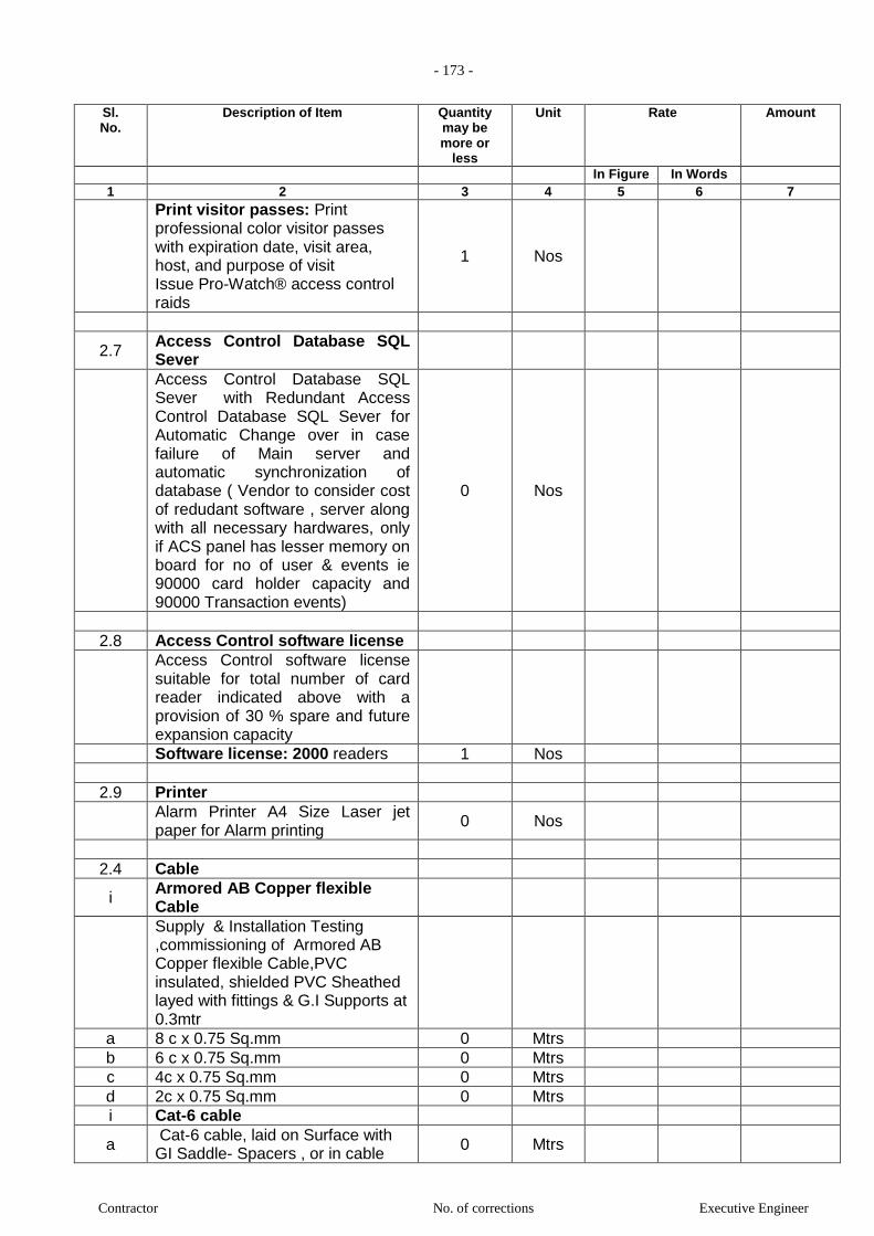
- 173 -
Contractor No. of corrections Executive Engineer
Sl. No.
Description of Item Quantity may be more or
less
Unit Rate Amount
In Figure In Words 1 2 3 4 5 6 7
Print visitor passes: Print professional color visitor passes with expiration date, visit area, host, and purpose of visit Issue Pro-Watch® access control raids
1 Nos
2.7 Access Control Database SQL Sever
Access Control Database SQL Sever with Redundant Access Control Database SQL Sever for Automatic Change over in case failure of Main server and automatic synchronization of database ( Vendor to consider cost of redudant software , server along with all necessary hardwares, only if ACS panel has lesser memory on board for no of user & events ie 90000 card holder capacity and 90000 Transaction events)
0 Nos
2.8 Access Control software license
Access Control software license suitable for total number of card reader indicated above with a provision of 30 % spare and future expansion capacity
Software license: 2000 readers 1 Nos
2.9 Printer
Alarm Printer A4 Size Laser jet paper for Alarm printing
0 Nos
2.4 Cable
i Armored AB Copper flexible Cable
Supply & Installation Testing ,commissioning of Armored AB Copper flexible Cable,PVC insulated, shielded PVC Sheathed layed with fittings & G.I Supports at 0.3mtr
a 8 c x 0.75 Sq.mm 0 Mtrs
b 6 c x 0.75 Sq.mm 0 Mtrs
c 4c x 0.75 Sq.mm 0 Mtrs
d 2c x 0.75 Sq.mm 0 Mtrs
i Cat-6 cable
a Cat-6 cable, laid on Surface with GI Saddle- Spacers , or in cable
0 Mtrs
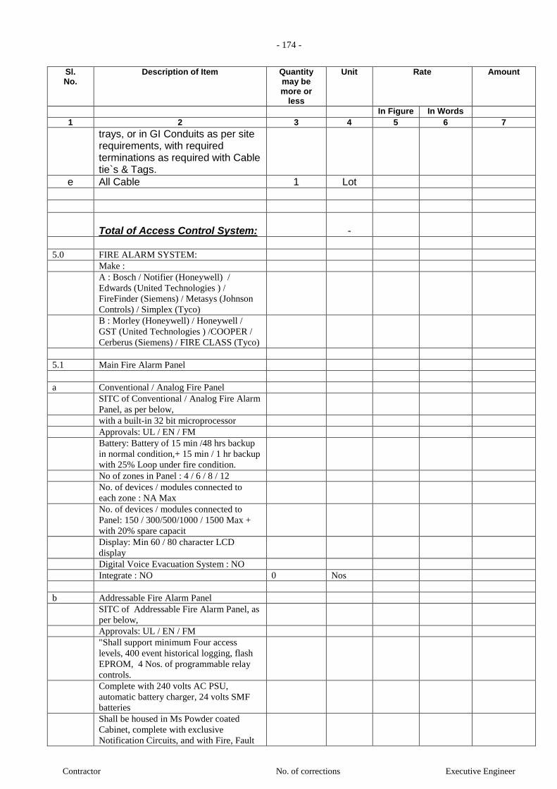
- 174 -
Contractor No. of corrections Executive Engineer
Sl. No.
Description of Item Quantity may be more or
less
Unit Rate Amount
In Figure In Words 1 2 3 4 5 6 7
trays, or in GI Conduits as per site requirements, with required terminations as required with Cable tie`s & Tags.
e All Cable 1 Lot
Total of Access Control System:
-
5.0 FIRE ALARM SYSTEM:
Make :
A : Bosch / Notifier (Honeywell) /
Edwards (United Technologies ) /
FireFinder (Siemens) / Metasys (Johnson
Controls) / Simplex (Tyco)
B : Morley (Honeywell) / Honeywell /
GST (United Technologies ) /COOPER /
Cerberus (Siemens) / FIRE CLASS (Tyco)
5.1 Main Fire Alarm Panel
a Conventional / Analog Fire Panel
SITC of Conventional / Analog Fire Alarm
Panel, as per below,
with a built-in 32 bit microprocessor
Approvals: UL / EN / FM
Battery: Battery of 15 min /48 hrs backup
in normal condition,+ 15 min / 1 hr backup
with 25% Loop under fire condition.
No of zones in Panel : 4 / 6 / 8 / 12
No. of devices / modules connected to
each zone : NA Max
No. of devices / modules connected to
Panel: 150 / 300/500/1000 / 1500 Max +
with 20% spare capacit
Display: Min 60 / 80 character LCD
display
Digital Voice Evacuation System : NO
Integrate : NO 0 Nos
b Addressable Fire Alarm Panel
SITC of Addressable Fire Alarm Panel, as
per below,
Approvals: UL / EN / FM
"Shall support minimum Four access
levels, 400 event historical logging, flash
EPROM, 4 Nos. of programmable relay
controls.
Complete with 240 volts AC PSU,
automatic battery charger, 24 volts SMF
batteries
Shall be housed in Ms Powder coated
Cabinet, complete with exclusive
Notification Circuits, and with Fire, Fault
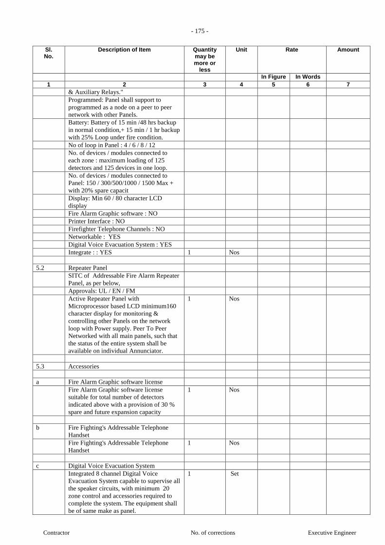
- 175 -
Contractor No. of corrections Executive Engineer
Sl. No.
Description of Item Quantity may be more or
less
Unit Rate Amount
In Figure In Words 1 2 3 4 5 6 7
& Auxiliary Relays."
Programmed: Panel shall support to
programmed as a node on a peer to peer
network with other Panels.
Battery: Battery of 15 min /48 hrs backup
in normal condition,+ 15 min / 1 hr backup
with 25% Loop under fire condition.
No of loop in Panel : 4 / 6 / 8 / 12
No. of devices / modules connected to
each zone : maximum loading of 125
detectors and 125 devices in one loop.
No. of devices / modules connected to
Panel: 150 / 300/500/1000 / 1500 Max +
with 20% spare capacit
Display: Min 60 / 80 character LCD
display
Fire Alarm Graphic software : NO
Printer Interface : NO
Firefighter Telephone Channels : NO
Networkable : YES
Digital Voice Evacuation System : YES
Integrate : : YES 1 Nos
5.2 Repeater Panel
SITC of Addressable Fire Alarm Repeater
Panel, as per below,
Approvals: UL / EN / FM
Active Repeater Panel with
Microprocessor based LCD minimum160
character display for monitoring &
controlling other Panels on the network
loop with Power supply. Peer To Peer
Networked with all main panels, such that
the status of the entire system shall be
available on individual Annunciator.
1 Nos
5.3 Accessories
a Fire Alarm Graphic software license
Fire Alarm Graphic software license
suitable for total number of detectors
indicated above with a provision of 30 %
spare and future expansion capacity
1 Nos
b Fire Fighting's Addressable Telephone
Handset
Fire Fighting's Addressable Telephone
Handset
1 Nos
c Digital Voice Evacuation System
Integrated 8 channel Digital Voice
Evacuation System capable to supervise all
the speaker circuits, with minimum 20
zone control and accessories required to
complete the system. The equipment shall
be of same make as panel.
1 Set

- 176 -
Contractor No. of corrections Executive Engineer
Sl. No.
Description of Item Quantity may be more or
less
Unit Rate Amount
In Figure In Words 1 2 3 4 5 6 7
d PC
Fire Alarm Graphic PC as per Technical
Specifications for monitoring fire detection
systems
0 Nos
e Printer
Alarm Printer A4 Size lasejet paper for
Alarm printing
0 Nos
f Operator Terminals
Operator Terminals for viewing the
Graphics at remote location
0 Lot
5.4 Detector
a Smoke Detector
SITC of Analogue Addressable
Photoelectric type Smoke Detector,
sensitivity range of 0.5% to 2.35% /ft with
Detector base, complete with MS Powder
coated Junction Box for
Approvals: UL / EN / FM
a.i Mounting on Surface / Below False
Ceiling
36 Nos
a.ii Mounting on Below False Floor. 2 Nos
a.iii Mounting on on above False Ceiling 11 Nos
with Response Indicator
SITC of Response Indicator having twin
LED flush mounted on false ceiling/wall
48 Nos
b Photoelectric + thermal Multi-sensor
Detector
Approvals: UL / EN / FM
SITC of Analogue Addressable
Photoelectric + thermal Multi-sensor
Detector with Detector base, complete
with MS Powder coated Junction Box for
mounting on Surface / on False Ceiling /
Below False Floor.
2 Nos
c Heat detector
Approvals: UL / EN / FM
SITC of Analogue Addressable Heat
detector, Rate of Rise Cum Fixed
temperature detector , complete with MS
Powder coated Junction Box for mouting
on Surface / on False Ceiling / Below
False Floor.
200 Nos
d Reflective Type Beam detector
Approvals: UL / EN / FM
SITC of Reflective Type Beam
detector,black powder coated 70mtrx5mtr
0 Nos
5.5 Manual Call Point

- 177 -
Contractor No. of corrections Executive Engineer
Sl. No.
Description of Item Quantity may be more or
less
Unit Rate Amount
In Figure In Words 1 2 3 4 5 6 7
Approvals: UL / EN / FM
SITC of Conventional Manual Call Point
In ABS Enclosure.
16 Nos
5.6 Dual Action Manual Pull Station
Approvals: UL / EN / FM
SITC of Addressable Dual Action Manual
Pull Station with Reset Lock & Key
arrangement with mounting Accessories.
0 Nos
5.7 Monitor Modules
Approvals: UL / EN / FM
SITC of Addressable Monitor Modules
with MS Powder coated Housing and
mounting accessories.
4 Nos
5.8 Flow Switch
Addressable monitor module required to
monitor status like flow Switch in Fire
fighting and other applications
4 No
5.9 Control Modules
Approvals: UL / EN / FM
SITC of Addressable Control Modules
with MS Powder coated Housing and
mounting accessories. Wherever Control
Modules shall be used for Tripping of
Third Party systems (AHUs / Electrical
Breakers etc.), Pilot Relays shall be
provided by the FAS vendor to route up to
240 V / 15 A current through the Pilot
Relay.
4 Nos
5.10 Hooter
Approvals: UL / EN / FM
Supply installation Testing &
commissioning of Ceiling / Wall mounted
Hooter cum Strobes. The Hooter cum
Strobes shall be made of ABS plastic and
have the Db level of 90dbs at 10ft and a
multi tone facility, Strobes intensity should
be 15 to 120 Candela.
a Ceiling mounted Hooter 16 Nos
b Wall mounted Hooter 4 Nos
c Ceiling mounted Hooter cum Strobes. 4 Nos
d Wall mounted Hooter cum Strobes. 4 Nos
5.11 Fault Isolator Modules
Approvals: UL / EN / FM
SITC of Fault Isolator Modules with MS
Powder coated Housing and mounting
accessories.
15 Nos
5.12 Panic Bar
Approvals: UL / EN / FM

- 178 -
Contractor No. of corrections Executive Engineer
Sl. No.
Description of Item Quantity may be more or
less
Unit Rate Amount
In Figure In Words 1 2 3 4 5 6 7
Supply installation Testing &
commissioning of Panic Bar, push to open
type with auxiliary PF contact, PF contact
shall be connected to Annunciater panel &
Local Hooter at Door.
10 Nos
5.13 Cable
Make : Polycab / Finolex / Vinay
"Supply installation of 2 Core x 1.5 mm2,
Twisted Pair , Multistranded AT Copper,
FRLS Armoured cable, RED in Colour.
The cable shall be laid on surface with GI
saddle-spacers every 0.3 meters. Complete
with GI Junction Box, lugs, cable
compression glands, cable tags and
Ferruling."
a 2 Core x 1.5 mm2, Multistranded 1 LOT
b 2 Core x 1.5 mm2, Multistranded 0 Mtrs
c 2 Core x 1.5 mm2, Twisted Pair 0 LOT
d 2 Core x 1.5 mm2, Twisted Pair 0 Mtrs
3.0 Total -
5.0 FIRE ALARM SYSTEM:
Make :
A : Bosch / Notifier (Honeywell) /
Edwards (United Technologies ) /
FireFinder (Siemens) / Metasys (Johnson
Controls) / Simplex (Tyco)
B : Morley (Honeywell) / Honeywell /
GST (United Technologies ) /COOPER /
Cerberus (Siemens) / FIRE CLASS (Tyco)
5.1 Main Fire Alarm Panel
a Conventional / Analog Fire Panel
SITC of Conventional / Analog Fire Alarm
Panel, as per below,
with a built-in 32 bit microprocessor
Approvals: UL / EN / FM
Battery: Battery of 15 min /48 hrs backup
in normal condition,+ 15 min / 1 hr backup
with 25% Loop under fire condition.
No of zones in Panel : 4 / 6 / 8 / 12
No. of devices / modules connected to
each zone : NA Max
No. of devices / modules connected to
Panel: 150 / 300/500/1000 / 1500 Max +
with 20% spare capacit
Display: Min 60 / 80 character LCD
display
Digital Voice Evacuation System : NO
Integrate : NO 0 Nos
b Addressable Fire Alarm Panel
SITC of Addressable Fire Alarm Panel, as

- 179 -
Contractor No. of corrections Executive Engineer
Sl. No.
Description of Item Quantity may be more or
less
Unit Rate Amount
In Figure In Words 1 2 3 4 5 6 7
per below,
Approvals: UL / EN / FM
"Shall support minimum Four access
levels, 400 event historical logging, flash
EPROM, 4 Nos. of programmable relay
controls.
Complete with 240 volts AC PSU,
automatic battery charger, 24 volts SMF
batteries
Shall be housed in Ms Powder coated
Cabinet, complete with exclusive
Notification Circuits, and with Fire, Fault
& Auxiliary Relays."
Programmed: Panel shall support to
programmed as a node on a peer to peer
network with other Panels.
Battery: Battery of 15 min /48 hrs backup
in normal condition,+ 15 min / 1 hr backup
with 25% Loop under fire condition.
No of loop in Panel : 4 / 6 / 8 / 12
No. of devices / modules connected to
each zone : maximum loading of 125
detectors and 125 devices in one loop.
No. of devices / modules connected to
Panel: 150 / 300/500/1000 / 1500 Max +
with 20% spare capacit
Display: Min 60 / 80 character LCD
display
Fire Alarm Graphic software : NO
Printer Interface : NO
Firefighter Telephone Channels : NO
Networkable : YES
Digital Voice Evacuation System : YES
Integrate : : YES 1 Nos
5.2 Repeater Panel
SITC of Addressable Fire Alarm Repeater Panel, as per below,
Approvals: UL / EN / FM
Active Repeater Panel with Microprocessor based LCD minimum160 character display for monitoring & controlling other Panels on the network loop with Power supply. Peer To Peer Networked with all main panels, such that the status of the entire system shall be available on individual Annunciator.
1 Nos
5.3 Accessories
a Fire Alarm Graphic software license
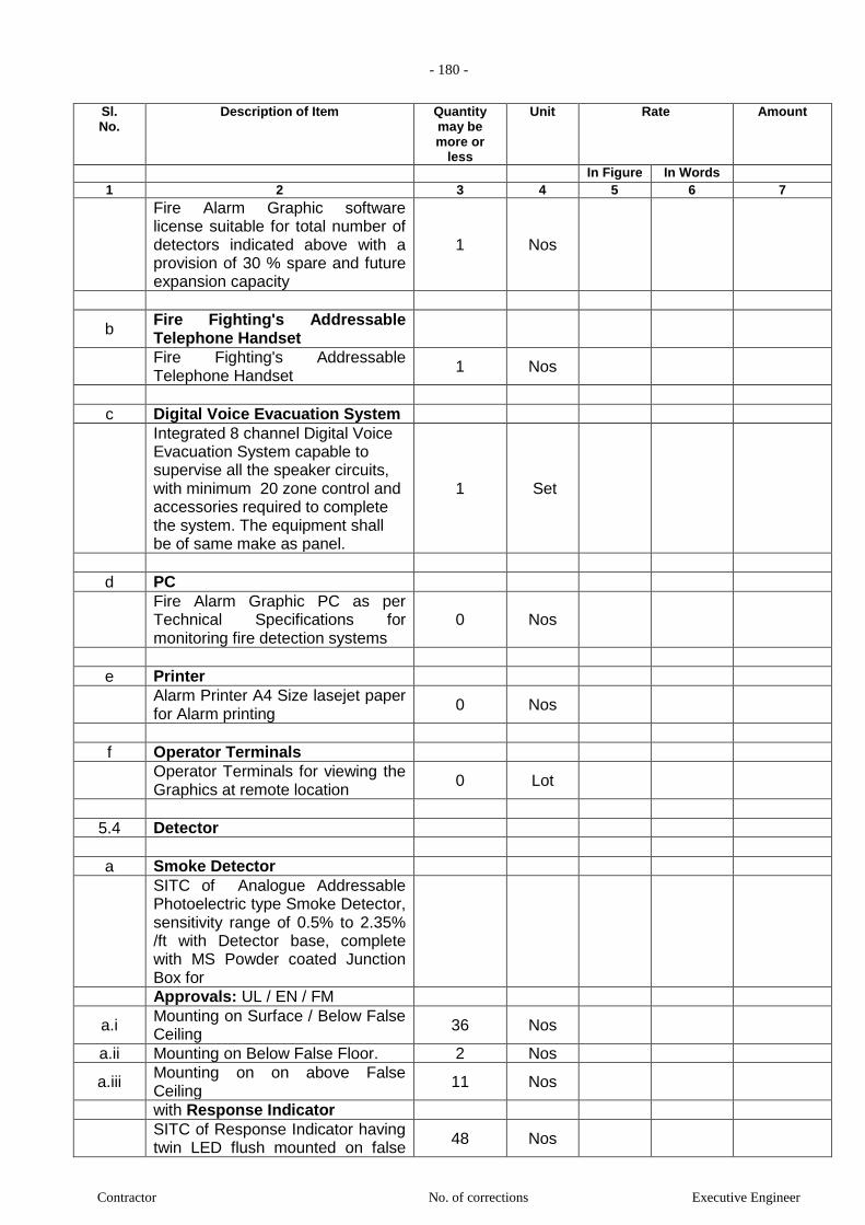
- 180 -
Contractor No. of corrections Executive Engineer
Sl. No.
Description of Item Quantity may be more or
less
Unit Rate Amount
In Figure In Words 1 2 3 4 5 6 7
Fire Alarm Graphic software license suitable for total number of detectors indicated above with a provision of 30 % spare and future expansion capacity
1 Nos
b Fire Fighting's Addressable Telephone Handset
Fire Fighting's Addressable Telephone Handset
1 Nos
c Digital Voice Evacuation System
Integrated 8 channel Digital Voice Evacuation System capable to supervise all the speaker circuits, with minimum 20 zone control and accessories required to complete the system. The equipment shall be of same make as panel.
1 Set
d PC
Fire Alarm Graphic PC as per Technical Specifications for monitoring fire detection systems
0 Nos
e Printer
Alarm Printer A4 Size lasejet paper for Alarm printing
0 Nos
f Operator Terminals
Operator Terminals for viewing the Graphics at remote location
0 Lot
5.4 Detector
a Smoke Detector
SITC of Analogue Addressable Photoelectric type Smoke Detector, sensitivity range of 0.5% to 2.35% /ft with Detector base, complete with MS Powder coated Junction Box for
Approvals: UL / EN / FM
a.i Mounting on Surface / Below False Ceiling
36 Nos
a.ii Mounting on Below False Floor. 2 Nos
a.iii Mounting on on above False Ceiling
11 Nos
with Response Indicator
SITC of Response Indicator having twin LED flush mounted on false
48 Nos

- 181 -
Contractor No. of corrections Executive Engineer
Sl. No.
Description of Item Quantity may be more or
less
Unit Rate Amount
In Figure In Words 1 2 3 4 5 6 7
ceiling/wall
b Photoelectric + thermal Multi-sensor Detector
Approvals: UL / EN / FM
SITC of Analogue Addressable Photoelectric + thermal Multi-sensor Detector with Detector base, complete with MS Powder coated Junction Box for mounting on Surface / on False Ceiling / Below False Floor.
2 Nos
c Heat detector
Approvals: UL / EN / FM
SITC of Analogue Addressable Heat detector, Rate of Rise Cum Fixed temperature detector , complete with MS Powder coated Junction Box for mouting on Surface / on False Ceiling / Below False Floor.
200 Nos
d Reflective Type Beam detector
Approvals: UL / EN / FM
SITC of Reflective Type Beam detector,black powder coated 70mtrx5mtr
0 Nos
5.5 Manual Call Point
Approvals: UL / EN / FM
SITC of Conventional Manual Call Point In ABS Enclosure.
16 Nos
5.6 Dual Action Manual Pull Station
Approvals: UL / EN / FM
SITC of Addressable Dual Action Manual Pull Station with Reset Lock & Key arrangement with mounting Accessories.
0 Nos
5.7 Monitor Modules
Approvals: UL / EN / FM
SITC of Addressable Monitor Modules with MS Powder coated Housing and mounting accessories.
4 Nos
5.8 Flow Switch
Addressable monitor module required to monitor status like flow
4 No
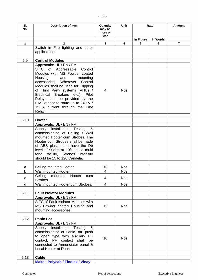
- 182 -
Contractor No. of corrections Executive Engineer
Sl. No.
Description of Item Quantity may be more or
less
Unit Rate Amount
In Figure In Words 1 2 3 4 5 6 7
Switch in Fire fighting and other applications
5.9 Control Modules
Approvals: UL / EN / FM
SITC of Addressable Control Modules with MS Powder coated Housing and mounting accessories. Wherever Control Modules shall be used for Tripping of Third Party systems (AHUs / Electrical Breakers etc.), Pilot Relays shall be provided by the FAS vendor to route up to 240 V / 15 A current through the Pilot Relay.
4 Nos
5.10 Hooter
Approvals: UL / EN / FM
Supply installation Testing & commissioning of Ceiling / Wall mounted Hooter cum Strobes. The Hooter cum Strobes shall be made of ABS plastic and have the Db level of 90dbs at 10ft and a multi tone facility, Strobes intensity should be 15 to 120 Candela.
a Ceiling mounted Hooter 16 Nos
b Wall mounted Hooter 4 Nos
c Ceiling mounted Hooter cum Strobes.
4 Nos
d Wall mounted Hooter cum Strobes. 4 Nos
5.11 Fault Isolator Modules
Approvals: UL / EN / FM
SITC of Fault Isolator Modules with MS Powder coated Housing and mounting accessories.
15 Nos
5.12 Panic Bar
Approvals: UL / EN / FM
Supply installation Testing & commissioning of Panic Bar, push to open type with auxiliary PF contact, PF contact shall be connected to Annunciater panel & Local Hooter at Door.
10 Nos
5.13 Cable
Make : Polycab / Finolex / Vinay
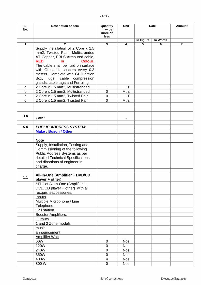
- 183 -
Contractor No. of corrections Executive Engineer
Sl. No.
Description of Item Quantity may be more or
less
Unit Rate Amount
In Figure In Words 1 2 3 4 5 6 7
Supply installation of 2 Core x 1.5 mm2, Twisted Pair , Multistranded AT Copper, FRLS Armoured cable, RED in Colour. The cable shall be laid on surface with GI saddle-spacers every 0.3 meters. Complete with GI Junction Box, lugs, cable compression glands, cable tags and Ferruling.
a 2 Core x 1.5 mm2, Multistranded 1 LOT
b 2 Core x 1.5 mm2, Multistranded 0 Mtrs
c 2 Core x 1.5 mm2, Twisted Pair 0 LOT
d 2 Core x 1.5 mm2, Twisted Pair 0 Mtrs
3.0 Total
-
6.0 PUBLIC ADDRESS SYSTEM:
Make : Bosch / Other
Note
Supply, Installation, Testing and Commissioning of the following Public Address Systems as per detailed Technical Specifications and directions of engineer in charge.
1.1 All-In-One (Amplifier + DVD/CD player + other)
SITC of All-In-One (Amplifier + DVD/CD player + other) with all recquisiteaccessories.
Inputs
Multiple Microphone / Line Telephone
Call station
Booster Amplifiers.
Outputs
1 and 2 Zone models
music
announcement
Amplifier Watt
60W 0 Nos
120W 0 Nos
240W 0 Nos
350W 0 Nos
400W 4 Nos
800 W 0 Nos
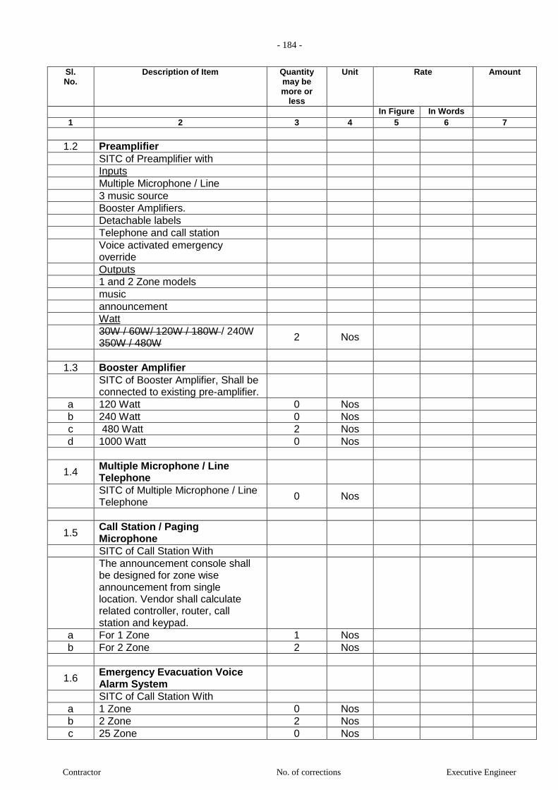
- 184 -
Contractor No. of corrections Executive Engineer
Sl. No.
Description of Item Quantity may be more or
less
Unit Rate Amount
In Figure In Words 1 2 3 4 5 6 7
1.2 Preamplifier
SITC of Preamplifier with
Inputs
Multiple Microphone / Line
3 music source
Booster Amplifiers.
Detachable labels
Telephone and call station
Voice activated emergency override
Outputs
1 and 2 Zone models
music
announcement
Watt
30W / 60W/ 120W / 180W / 240W 350W / 480W
2 Nos
1.3 Booster Amplifier
SITC of Booster Amplifier, Shall be connected to existing pre-amplifier.
a 120 Watt 0 Nos
b 240 Watt 0 Nos
c 480 Watt 2 Nos
d 1000 Watt 0 Nos
1.4 Multiple Microphone / Line Telephone
SITC of Multiple Microphone / Line Telephone
0 Nos
1.5 Call Station / Paging Microphone
SITC of Call Station With
The announcement console shall be designed for zone wise announcement from single location. Vendor shall calculate related controller, router, call station and keypad.
a For 1 Zone 1 Nos
b For 2 Zone 2 Nos
1.6 Emergency Evacuation Voice Alarm System
SITC of Call Station With
a 1 Zone 0 Nos
b 2 Zone 2 Nos
c 25 Zone 0 Nos
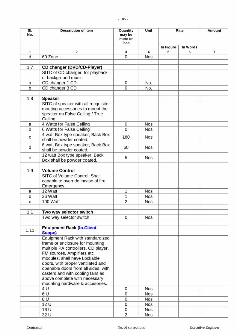
- 185 -
Contractor No. of corrections Executive Engineer
Sl. No.
Description of Item Quantity may be more or
less
Unit Rate Amount
In Figure In Words 1 2 3 4 5 6 7
d 60 Zone 0 Nos
1.7 CD changer (DVD/CD-Player)
SITC of CD changer for playback of background music
a CD changer 1 CD 0 No.
b CD changer 3 CD 0 No.
1.8 Speaker
SITC of speaker with all recquisite mouting accessories to mount the speaker on False Ceiling / True Ceiling.
a 4 Watts for False Ceiling 0 Nos
b 6 Watts for False Ceiling 0 Nos
c 4 watt Box type speaker, Back Box shall be powder coated.
180 Nos
d 6 watt Box type speaker, Back Box shall be powder coated.
60 Nos
e 12 watt Box type speaker, Back Box shall be powder coated.
5 Nos
1.9 Volume Control
SITC of Volume Control, Shall capable to override incase of fire Emergency.
a 12 Watt 1 Nos
b 36 Watt 1 Nos
c 100 Watt 2 Nos
1.1 Two way selector switch
Two way selector switch 0 Nos
1.11 Equipment Rack (In Client Scope)
Equipment Rack with standardized frame or enclosure for mounting multiple PA controllers, CD player, FM sources, Amplifiers etc modules, shall have Lockable doors, with proper ventilated and openable doors from all sides, with casters and with cooling fans as above complete with necessary mounting hardware & accesories.
4 U 0 Nos
6 U 0 Nos
8 U 0 Nos
12 U 0 Nos
16 U 0 Nos
32 U 2 Nos
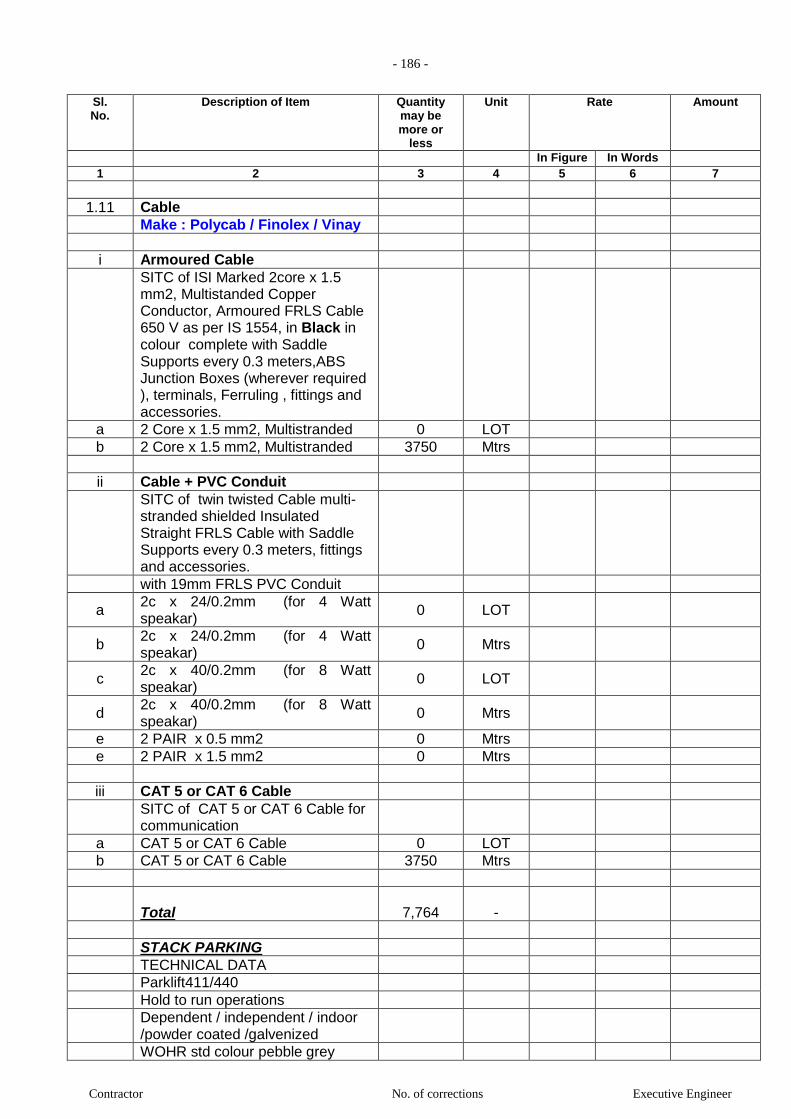
- 186 -
Contractor No. of corrections Executive Engineer
Sl. No.
Description of Item Quantity may be more or
less
Unit Rate Amount
In Figure In Words 1 2 3 4 5 6 7
1.11 Cable
Make : Polycab / Finolex / Vinay
i Armoured Cable
SITC of ISI Marked 2core x 1.5 mm2, Multistanded Copper Conductor, Armoured FRLS Cable 650 V as per IS 1554, in Black in colour complete with Saddle Supports every 0.3 meters,ABS Junction Boxes (wherever required ), terminals, Ferruling , fittings and accessories.
a 2 Core x 1.5 mm2, Multistranded 0 LOT
b 2 Core x 1.5 mm2, Multistranded 3750 Mtrs
ii Cable + PVC Conduit
SITC of twin twisted Cable multi-stranded shielded Insulated Straight FRLS Cable with Saddle Supports every 0.3 meters, fittings and accessories.
with 19mm FRLS PVC Conduit
a 2c x 24/0.2mm (for 4 Watt speakar)
0 LOT
b 2c x 24/0.2mm (for 4 Watt speakar)
0 Mtrs
c 2c x 40/0.2mm (for 8 Watt speakar)
0 LOT
d 2c x 40/0.2mm (for 8 Watt speakar)
0 Mtrs
e 2 PAIR x 0.5 mm2 0 Mtrs
e 2 PAIR x 1.5 mm2 0 Mtrs
iii CAT 5 or CAT 6 Cable
SITC of CAT 5 or CAT 6 Cable for communication
a CAT 5 or CAT 6 Cable 0 LOT
b CAT 5 or CAT 6 Cable 3750 Mtrs
Total
7,764
-
STACK PARKING
TECHNICAL DATA
Parklift411/440
Hold to run operations
Dependent / independent / indoor /powder coated /galvenized
WOHR std colour pebble grey

- 187 -
Contractor No. of corrections Executive Engineer
Sl. No.
Description of Item Quantity may be more or
less
Unit Rate Amount
In Figure In Words 1 2 3 4 5 6 7
2.0 ton
Electromagentic locks lockers from top to bottom at every 1000mm to ensure maximum safety
Emergency stop switch & hydraulic non return valve
WOHR standard corrugated design in galvenised
Wohr parlift 411 Ground level Galvenized
18 Nos.
Wohr parlift 440 Basement 3 level Powder coated
20 Nos.
TOTAL OF STACK PARKING
ELEVATORS
Gearless with machine room 16 stops 1.75 m/s power door
4 Nos.
TOTAL OF ELEVATORS
1. Item for which no rate or price has been entered in will not be paid for by the Employer when
executed and shall be deemed covered by the other rates and prices in the bill of quantities (Refer:
ITB Clause 13.2 and GCC Clause 43.3)
2. Unit rates and prices shall be quoted by the bidder in Indian rupee [ITB Clause 14.1]
3. Where there is a discrepancy between the rate in figure and words, the rates in word will govern [ITB
Clause 27.1(a)]
4. Where there is a discrepancy between the unit rate and the line item total resulting from multiplying
the unit rate by quantity, the unit rate quoted shall govern [ITB Clause 27.1(b)]
SPECIFICATIONS
Item
No.
Description Ref. to Std.
Spn. Book
Item No and
Page
Additional Specification
if any
1 Item No.1: Providing and casting Ready Mix M-30 grade
cement concrete for reinforced cement concrete work of cast in
situ bored piles 475 mm diameter using cement content as per
approved design mix, including pumping of concrete to site of
laying and the cost of centering, shuttering, finishing and
excluding reinforcement, including admixtures in recommended
proportions as per IS:9103 to accelerate, retard setting of
concrete. Improve workability without impairing strength and
durability as per direction of Engineer – in – charge. The mix
design as per particular specification shall be got approved by
Engineer – in – charge before execution of item. The rate shall
include cost of all specified materials and operation at all levels
and heights, including the cost of centering, steel/waterproof
plywood shuttering and excluding reinforcement which shall be
paid under relevant item.( Note:- minimum Cement content
( Note:- minimum Cement
content considered in this
item is @ 400 kg/cum as
per IS 455 table showing
minimum cement content.
No extra charges will be
paid on account of
variation of cement in mix
design as per specifications
for controlled concrete i.e.
beyond 400kg/cum)
As per rotary
method

- 188 -
Contractor No. of corrections Executive Engineer
Item
No.
Description Ref. to Std.
Spn. Book
Item No and
Page
Additional Specification
if any
considered in this item is @ 400 kg/cum as per IS 455 table
showing minimum cement content. No extra charges will be
paid on account of variation of cement in mix design as per
specifications for controlled concrete i.e.beyond 400kg/cum) (As
per rotary Method)
2 Item No.2: Providing and casting Ready Mix M-30 grade
cement concrete for reinforced cement concrete work,of cast in
situ bored piles 600 mm diameter using cement content as per
approved design mix, including pumping of concrete to site of
laying and the cost of centering, shuttering, finishing and
excluding reinforcement, including admixtures in recommended
proportions as per IS:9103 to accelerate, retard setting of
concrete. Improve workability without impairing strength and
durability as per direction of Engineer – in – charge. The mix
design as per particular specification shall be got approved by
Engineer – in – charge before execution of item. The rate shall
include cost of all specified materials and operation at all levels
and heights, including the cost of centering, steel/waterproof
plywood shuttering and excluding reinforcement which shall be
paid under relevant item.( Note:- minimum Cement content
considered in this item is @ 400 kg/cum as per IS 455 table
showing minimum cement content. No extra charges will be
paid on account of variation of cement in mix design as per
specifications for controlled concrete i.e. beyond 400kg/cum)
(As per rotary Method)
As per rotary
method
( Note:- minimum Cement
content considered in this
item is @ 400 kg/cum as
per IS 455 table showing
minimum cement content.
No extra charges will be
paid on account of
variation of cement in mix
design as per specifications
for controlled concrete i.e.
beyond 400kg/cum)
3 Item No.3: Providing and casting Ready Mix M-30 grade cement
concrete for reinforced cement concrete work of cast in situ
bored piles 750 mm diameter using cement content as per
approved design mix, including pumping of concrete to site of
laying and the cost of centering, shuttering, finishing and
excluding reinforcement, including admixtures in recommended
proportions as per IS:9103 to accelerate, retard setting of
concrete. Improve workability without impairing strength and
durability as per direction of Engineer – in – charge. The mix
design as per particular specification shall be got approved by
Engineer – in – charge before execution of item. The rate shall
include cost of all specified materials and operation at all levels
and heights, including the cost of centering, steel/waterproof
plywood shuttering and excluding reinforcement which shall be
paid under relevant item.( Note:- minimum Cement content
considered in this item is @ 400 kg/cum as per IS 455 table
showing minimum cement content. No extra charges will be
paid on account of variation of cement in mix design as per
specifications for controlled concrete i.e. beyond 400kg/cum)
(As per rotary Method)
As per rotary
method
( Note:- minimum Cement
content considered in this
item is @ 400 kg/cum as
per IS 455 table showing
minimum cement content.
No extra charges will be
paid on account of
variation of cement in mix
design as per specifications
for controlled concrete i.e.
beyond 400kg/cum)
4 Item No.4:- Providing placing and Driving in position mild steel
liner for R.C.C. Piles 6 millimeter thick permanent mild steel
The work shall be carried
out as per the wording of
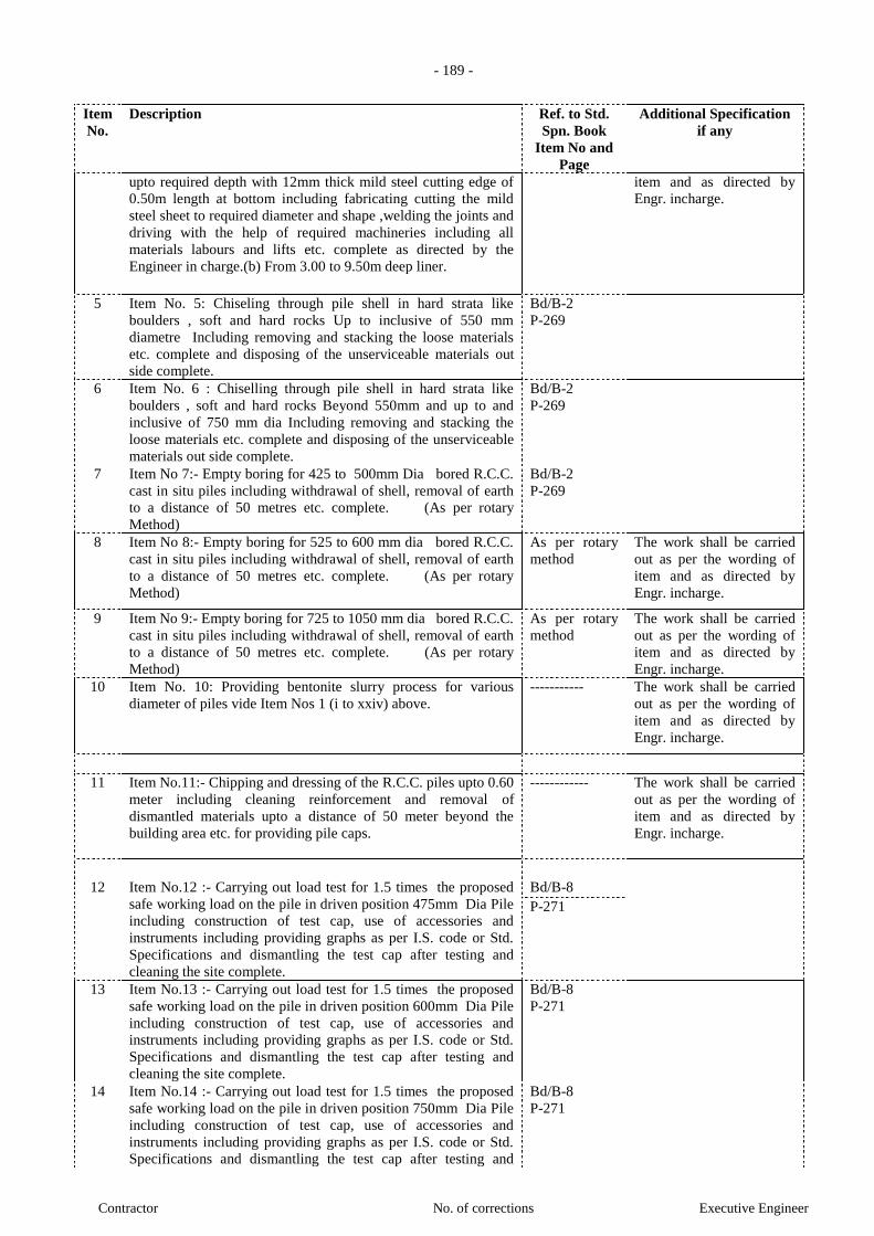
- 189 -
Contractor No. of corrections Executive Engineer
Item
No.
Description Ref. to Std.
Spn. Book
Item No and
Page
Additional Specification
if any
upto required depth with 12mm thick mild steel cutting edge of
0.50m length at bottom including fabricating cutting the mild
steel sheet to required diameter and shape ,welding the joints and
driving with the help of required machineries including all
materials labours and lifts etc. complete as directed by the
Engineer in charge.(b) From 3.00 to 9.50m deep liner.
item and as directed by
Engr. incharge.
5 Item No. 5: Chiseling through pile shell in hard strata like
boulders , soft and hard rocks Up to inclusive of 550 mm
diametre Including removing and stacking the loose materials
etc. complete and disposing of the unserviceable materials out
side complete.
Bd/B-2
P-269
6 Item No. 6 : Chiselling through pile shell in hard strata like
boulders , soft and hard rocks Beyond 550mm and up to and
inclusive of 750 mm dia Including removing and stacking the
loose materials etc. complete and disposing of the unserviceable
materials out side complete.
Bd/B-2
P-269
7 Item No 7:- Empty boring for 425 to 500mm Dia bored R.C.C.
cast in situ piles including withdrawal of shell, removal of earth
to a distance of 50 metres etc. complete. (As per rotary
Method)
Bd/B-2
P-269
8 Item No 8:- Empty boring for 525 to 600 mm dia bored R.C.C.
cast in situ piles including withdrawal of shell, removal of earth
to a distance of 50 metres etc. complete. (As per rotary
Method)
As per rotary
method
The work shall be carried
out as per the wording of
item and as directed by
Engr. incharge.
9 Item No 9:- Empty boring for 725 to 1050 mm dia bored R.C.C.
cast in situ piles including withdrawal of shell, removal of earth
to a distance of 50 metres etc. complete. (As per rotary
Method)
As per rotary
method
The work shall be carried
out as per the wording of
item and as directed by
Engr. incharge.
10 Item No. 10: Providing bentonite slurry process for various
diameter of piles vide Item Nos 1 (i to xxiv) above.
----------- The work shall be carried
out as per the wording of
item and as directed by
Engr. incharge.
11 Item No.11:- Chipping and dressing of the R.C.C. piles upto 0.60
meter including cleaning reinforcement and removal of
dismantled materials upto a distance of 50 meter beyond the
building area etc. for providing pile caps.
------------ The work shall be carried
out as per the wording of
item and as directed by
Engr. incharge.
12 Item No.12 :- Carrying out load test for 1.5 times the proposed
safe working load on the pile in driven position 475mm Dia Pile
including construction of test cap, use of accessories and
instruments including providing graphs as per I.S. code or Std.
Specifications and dismantling the test cap after testing and
cleaning the site complete.
Bd/B-8
P-271
13 Item No.13 :- Carrying out load test for 1.5 times the proposed
safe working load on the pile in driven position 600mm Dia Pile
including construction of test cap, use of accessories and
instruments including providing graphs as per I.S. code or Std.
Specifications and dismantling the test cap after testing and
cleaning the site complete.
Bd/B-8
P-271
14 Item No.14 :- Carrying out load test for 1.5 times the proposed
safe working load on the pile in driven position 750mm Dia Pile
including construction of test cap, use of accessories and
instruments including providing graphs as per I.S. code or Std.
Specifications and dismantling the test cap after testing and
Bd/B-8
P-271

- 190 -
Contractor No. of corrections Executive Engineer
Item
No.
Description Ref. to Std.
Spn. Book
Item No and
Page
Additional Specification
if any
cleaning the site complete.
15 Item No.15 :- Pile integrated test Conducting pile integrity test
as per IS 14893 and submitting reports and graphs including all
necessary preparation fot the test etc. complete (475mm Dia
Pile)
------------ The work shall be carried
out as per the wording of
item and as directed by
Engr. incharge.
16 Item No.16 :- Pile integrated test Conducting pile integrity test
as per IS 14893 and submitting reports and graphs including all
necessary preparation fot the test etc. complete (600mm Dia
Pile)
------------ The work shall be carried
out as per the wording of
item and as directed by
Engr. incharge.
17 Item No.17 :- Pile integrated test Conducting pile integraty test
as per IS 14893 and submitting reports and graphs including all
necessary preparation fot the test etc. complete (750mm Dia Pile
)
------------ The work shall be carried
out as per the wording of
item and as directed by
Engr. incharge.
18 Item No.18 :- Excavation for foundation in earth, soil of all
types, sand, gravel and soft murum. including removing the
excavated materials up to a distance of 50 metres beyond the
building area and lift upto 1.50 metres, stacking and spreading as
directed including dewatering unless provided elsewhere,
preparing the bed for the foundation and necessary backfilling,
ramming, watering complete excluding shoring and strutting.
Bd/A-1
P-259
19 Item No.19 :-Excavation for foundation in earth, soil of all types,
sand, gravel and soft murum. including removing the excavated
materials up to a distance of 50 metres beyond the building area,
stacking and spreading as directed including dewatering
manually, preparing the bed for the foundation and necessary
backfilling, ramming, watering complete excluding shoring and
strutting. (Add for every additional vertical lift of 1.50 metres)
For lift above 1.5m to 3.00m
Bd/A-1
P-259
20 Item No.20 :-Excavation for foundation in earth, soil of all types,
sand, gravel and soft murum. including removing the excavated
materials up to a distance of 50 metres beyond the building area,
stacking and spreading as directed including dewatering
manually, preparing the bed for the foundation and necessary
backfilling, ramming, watering complete excluding shoring and
strutting. (Add for every additional vertical lift of 1.50 metres)
For lift above 3.0m to 4.5m
Bd/A-1
P-259
21 Item No.21 :-Excavation for foundation in earth, soil of all
types, sand, gravel and soft murum. including removing the
excavated materials up to a distance of 50 metres beyond the
building area, stacking and spreading as directed including
dewatering manually, preparing the bed for the foundation and
necessary backfilling, ramming, watering complete excluding
shoring and strutting. (Add for every additional vertical lift of
1.50 metres) For lift above 4.5m to 6m
Bd/A-1
P-259
22 Item No.22 :-Excavation for foundation in earth, soil of all types,
sand, gravel and soft murum. including removing the excavated
materials up to a distance of 50 metres beyond the building area,
stacking and spreading as directed including dewatering
manually, preparing the bed for the foundation and necessary
backfilling, ramming, watering complete excluding shoring and
strutting. (Add for every additional vertical lift of 1.50 metres)
For lift above 6.00m to 7.5m
Bd/A-1
P-259
23 Item No.23 :-Excavation for foundation in earth, soil of all
types, sand, gravel and soft murum. including removing the
excavated materials up to a distance of 50 metres beyond the
Bd/A-1
P-259
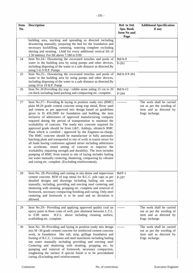
- 191 -
Contractor No. of corrections Executive Engineer
Item
No.
Description Ref. to Std.
Spn. Book
Item No and
Page
Additional Specification
if any
building area, stacking and spreading as directed including
dewatering manually, preparing the bed for the foundation and
necessary backfilling, ramming, watering complete excluding
shoring and strutting. (Add for every additional vertical lift of
1.50 metres) For lift above 7.5M to 9.00
24 Item No.24:- Dewatering the excavated trenches and pools of
water in the building area by using pumps and other devices,
including disposing of the water to a safe distance as directed.By
using 5 to 9 H.P. Pumps
Bd/A-9
P-261
25 Item No.25:- Dewatering the excavated trenches and pools of
water in the building area by using pumps and other devices,
including disposing of the water to a safe distance as directed.By
using 10 to 19 H.P. Pump
Bd/A-9 P-261
26 Item No 26:Providing dry trap / rubble stone soling 15 cm to 20
cm thick including hand packing and compacting etc. complete.
Bd/A-12
P-264
27 Item No.27:- Providing & laying in position ready mix (RMC)
plain M-20 grade cement concrete using trap metal, River sand
and cement as per approved mix design based on guidelines
given in IS 456:2000 for foundation and bedding, the item
inclusive of admixtures of approved manufacturing company
required during the period of transportation to maintain the
workability of concrete. The ready mix concrete required for
approved grade should be from L&T, Ambuja, ultratech RMC
Plant which is certified / approved by the Engineer-in-charge.
The RMC concrete should be manufacture in fully automatic
batching plant and transported to site of work in transit mixer for
all leads having continuous agitated mixer including admixtures
to accelerate, retard setting of concrete to improve the
workability impairing strength and durability. The item includes
pumping of RMC from transit to site of laying includes bailing
out water manually centering, shuttering, compacting by vibrator
and curing etc. complete. (Excluding reinforcement).
--------- The work shall be carried
out as per the wording of
item and as directed by
Engr. incharge.
28 Item No. 28:-Providing and casting in situ dense and impervious
cement concrete. M30 of trap metal for R.C.C. pile caps as per
detailed designs and drawings including bailing out water
manually, including, providing and erecting steel centering and
shuttering with strutting, propping etc. complete and removal of
formwork, necessary compacting finishing and curing. Only steel
centering and formwork is to be used and no deviation is
allowed.
Bd/F-1
P-297
29 Item No.29:- Providing and applying approved quality coal tar
epoxy paint in three coats of well, pier abutment between L.T.L.
to 0.90 metre H.F.L. above including cleaning surface,
scaffolding etc. complate.
------- The work shall be carried
out as per the wording of
item and as directed by
Engr. incharge.
30 Item No. 30:-Providing and laying in position ready mix design
mix M -30 grade cement concrete for reinforced cement concrete
work, in foundation like raft, strip, grillage foundation and
footing of R.C.C. Columns and steel stanchions including bailing
out water manually including providing and erecting steel
Centering and shuttering with strutting, propping etc, by
pumping and removal of formwork, necessary compaction,
roughening the surface if special finish is to be providedand
curing. (Excluding steel reinforcement)
------- The work shall be carried
out as per the wording of
item and as directed by
Engr. incharge.
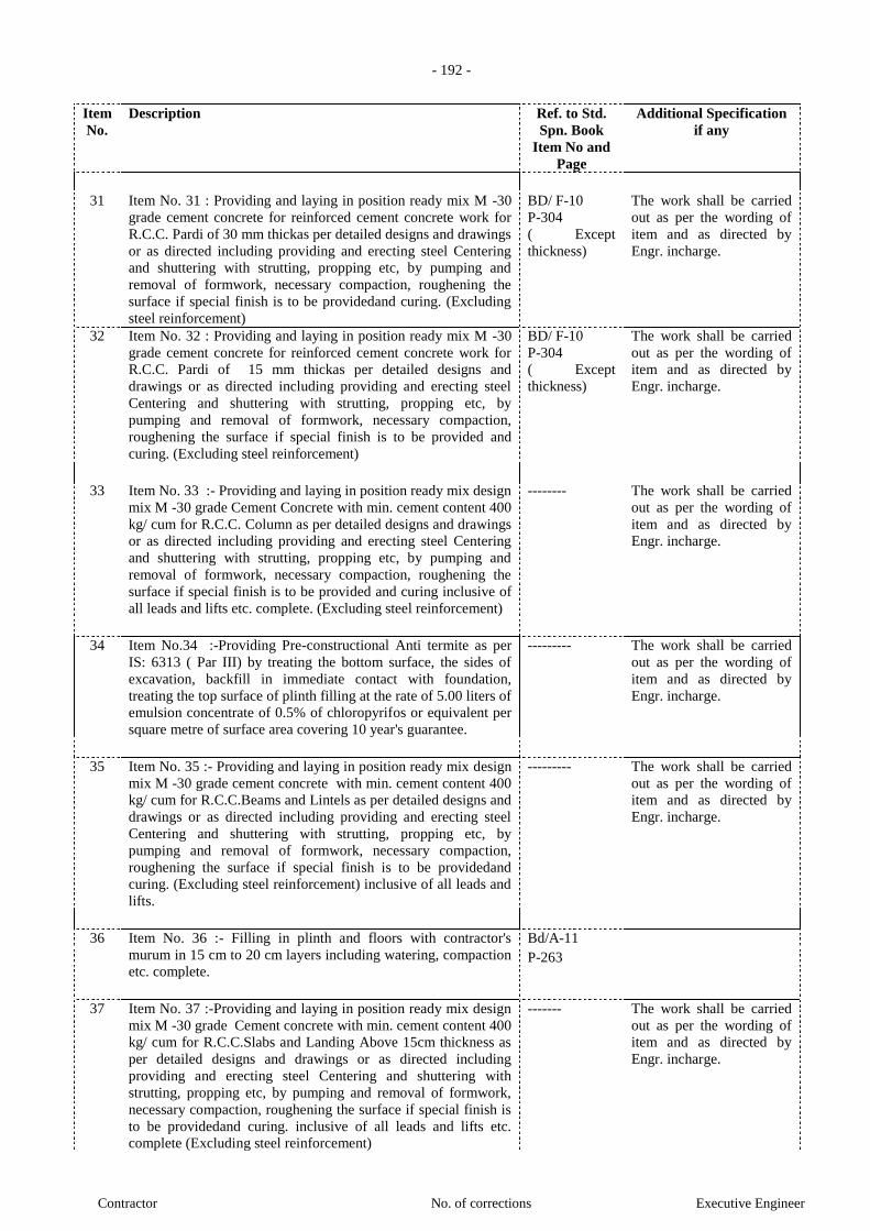
- 192 -
Contractor No. of corrections Executive Engineer
Item
No.
Description Ref. to Std.
Spn. Book
Item No and
Page
Additional Specification
if any
31 Item No. 31 : Providing and laying in position ready mix M -30
grade cement concrete for reinforced cement concrete work for
R.C.C. Pardi of 30 mm thickas per detailed designs and drawings
or as directed including providing and erecting steel Centering
and shuttering with strutting, propping etc, by pumping and
removal of formwork, necessary compaction, roughening the
surface if special finish is to be providedand curing. (Excluding
steel reinforcement)
BD/ F-10
P-304
( Except
thickness)
The work shall be carried
out as per the wording of
item and as directed by
Engr. incharge.
32 Item No. 32 : Providing and laying in position ready mix M -30
grade cement concrete for reinforced cement concrete work for
R.C.C. Pardi of 15 mm thickas per detailed designs and
drawings or as directed including providing and erecting steel
Centering and shuttering with strutting, propping etc, by
pumping and removal of formwork, necessary compaction,
roughening the surface if special finish is to be provided and
curing. (Excluding steel reinforcement)
BD/ F-10
P-304
( Except
thickness)
The work shall be carried
out as per the wording of
item and as directed by
Engr. incharge.
33 Item No. 33 :- Providing and laying in position ready mix design
mix M -30 grade Cement Concrete with min. cement content 400
kg/ cum for R.C.C. Column as per detailed designs and drawings
or as directed including providing and erecting steel Centering
and shuttering with strutting, propping etc, by pumping and
removal of formwork, necessary compaction, roughening the
surface if special finish is to be provided and curing inclusive of
all leads and lifts etc. complete. (Excluding steel reinforcement)
-------- The work shall be carried
out as per the wording of
item and as directed by
Engr. incharge.
34 Item No.34 :-Providing Pre-constructional Anti termite as per
IS: 6313 ( Par III) by treating the bottom surface, the sides of
excavation, backfill in immediate contact with foundation,
treating the top surface of plinth filling at the rate of 5.00 liters of
emulsion concentrate of 0.5% of chloropyrifos or equivalent per
square metre of surface area covering 10 year's guarantee.
--------- The work shall be carried
out as per the wording of
item and as directed by
Engr. incharge.
35 Item No. 35 :- Providing and laying in position ready mix design
mix M -30 grade cement concrete with min. cement content 400
kg/ cum for R.C.C.Beams and Lintels as per detailed designs and
drawings or as directed including providing and erecting steel
Centering and shuttering with strutting, propping etc, by
pumping and removal of formwork, necessary compaction,
roughening the surface if special finish is to be providedand
curing. (Excluding steel reinforcement) inclusive of all leads and
lifts.
--------- The work shall be carried
out as per the wording of
item and as directed by
Engr. incharge.
36 Item No. 36 :- Filling in plinth and floors with contractor's
murum in 15 cm to 20 cm layers including watering, compaction
etc. complete.
Bd/A-11
P-263
37 Item No. 37 :-Providing and laying in position ready mix design
mix M -30 grade Cement concrete with min. cement content 400
kg/ cum for R.C.C.Slabs and Landing Above 15cm thickness as
per detailed designs and drawings or as directed including
providing and erecting steel Centering and shuttering with
strutting, propping etc, by pumping and removal of formwork,
necessary compaction, roughening the surface if special finish is
to be providedand curing. inclusive of all leads and lifts etc.
complete (Excluding steel reinforcement)
------- The work shall be carried
out as per the wording of
item and as directed by
Engr. incharge.
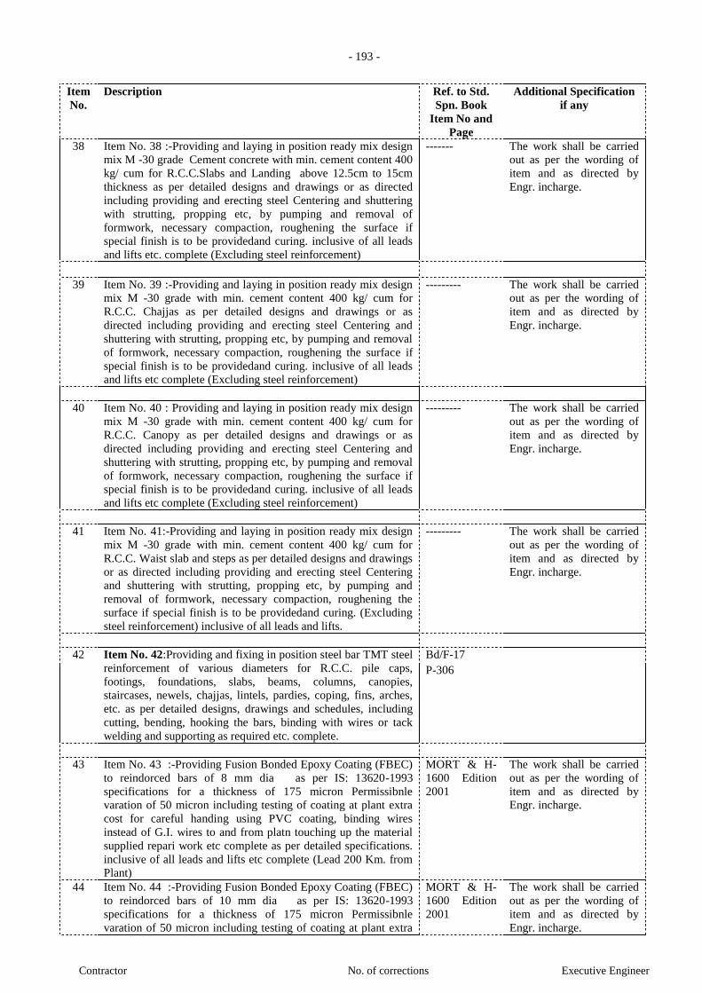
- 193 -
Contractor No. of corrections Executive Engineer
Item
No.
Description Ref. to Std.
Spn. Book
Item No and
Page
Additional Specification
if any
38 Item No. 38 :-Providing and laying in position ready mix design
mix M -30 grade Cement concrete with min. cement content 400
kg/ cum for R.C.C.Slabs and Landing above 12.5cm to 15cm
thickness as per detailed designs and drawings or as directed
including providing and erecting steel Centering and shuttering
with strutting, propping etc, by pumping and removal of
formwork, necessary compaction, roughening the surface if
special finish is to be providedand curing. inclusive of all leads
and lifts etc. complete (Excluding steel reinforcement)
------- The work shall be carried
out as per the wording of
item and as directed by
Engr. incharge.
39 Item No. 39 :-Providing and laying in position ready mix design
mix M -30 grade with min. cement content 400 kg/ cum for
R.C.C. Chajjas as per detailed designs and drawings or as
directed including providing and erecting steel Centering and
shuttering with strutting, propping etc, by pumping and removal
of formwork, necessary compaction, roughening the surface if
special finish is to be providedand curing. inclusive of all leads
and lifts etc complete (Excluding steel reinforcement)
--------- The work shall be carried
out as per the wording of
item and as directed by
Engr. incharge.
40 Item No. 40 : Providing and laying in position ready mix design
mix M -30 grade with min. cement content 400 kg/ cum for
R.C.C. Canopy as per detailed designs and drawings or as
directed including providing and erecting steel Centering and
shuttering with strutting, propping etc, by pumping and removal
of formwork, necessary compaction, roughening the surface if
special finish is to be providedand curing. inclusive of all leads
and lifts etc complete (Excluding steel reinforcement)
--------- The work shall be carried
out as per the wording of
item and as directed by
Engr. incharge.
41 Item No. 41:-Providing and laying in position ready mix design
mix M -30 grade with min. cement content 400 kg/ cum for
R.C.C. Waist slab and steps as per detailed designs and drawings
or as directed including providing and erecting steel Centering
and shuttering with strutting, propping etc, by pumping and
removal of formwork, necessary compaction, roughening the
surface if special finish is to be providedand curing. (Excluding
steel reinforcement) inclusive of all leads and lifts.
--------- The work shall be carried
out as per the wording of
item and as directed by
Engr. incharge.
42 Item No. 42:Providing and fixing in position steel bar TMT steel
reinforcement of various diameters for R.C.C. pile caps,
footings, foundations, slabs, beams, columns, canopies,
staircases, newels, chajjas, lintels, pardies, coping, fins, arches,
etc. as per detailed designs, drawings and schedules, including
cutting, bending, hooking the bars, binding with wires or tack
welding and supporting as required etc. complete.
Bd/F-17
P-306
43 Item No. 43 :-Providing Fusion Bonded Epoxy Coating (FBEC)
to reindorced bars of 8 mm dia as per IS: 13620-1993
specifications for a thickness of 175 micron Permissibnle
varation of 50 micron including testing of coating at plant extra
cost for careful handing using PVC coating, binding wires
instead of G.I. wires to and from platn touching up the material
supplied repari work etc complete as per detailed specifications.
inclusive of all leads and lifts etc complete (Lead 200 Km. from
Plant)
MORT & H-
1600 Edition
2001
The work shall be carried
out as per the wording of
item and as directed by
Engr. incharge.
44 Item No. 44 :-Providing Fusion Bonded Epoxy Coating (FBEC)
to reindorced bars of 10 mm dia as per IS: 13620-1993
specifications for a thickness of 175 micron Permissibnle
varation of 50 micron including testing of coating at plant extra
MORT & H-
1600 Edition
2001
The work shall be carried
out as per the wording of
item and as directed by
Engr. incharge.
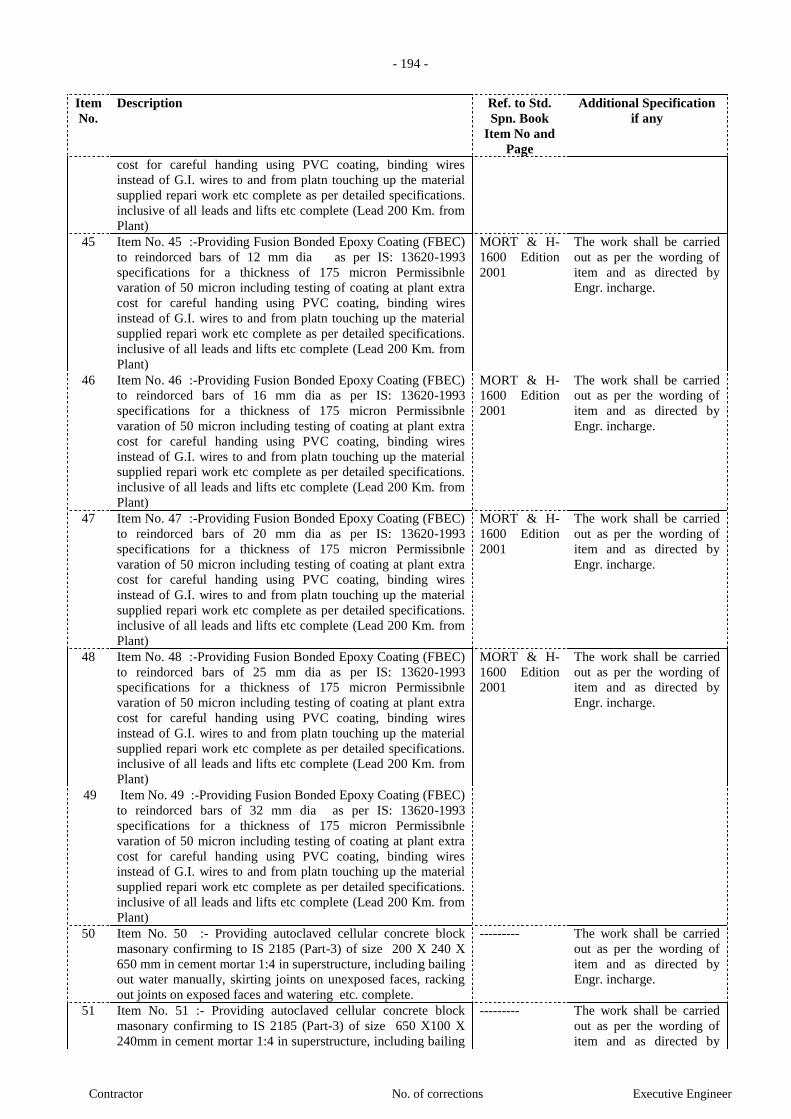
- 194 -
Contractor No. of corrections Executive Engineer
Item
No.
Description Ref. to Std.
Spn. Book
Item No and
Page
Additional Specification
if any
cost for careful handing using PVC coating, binding wires
instead of G.I. wires to and from platn touching up the material
supplied repari work etc complete as per detailed specifications.
inclusive of all leads and lifts etc complete (Lead 200 Km. from
Plant)
45 Item No. 45 :-Providing Fusion Bonded Epoxy Coating (FBEC)
to reindorced bars of 12 mm dia as per IS: 13620-1993
specifications for a thickness of 175 micron Permissibnle
varation of 50 micron including testing of coating at plant extra
cost for careful handing using PVC coating, binding wires
instead of G.I. wires to and from platn touching up the material
supplied repari work etc complete as per detailed specifications.
inclusive of all leads and lifts etc complete (Lead 200 Km. from
Plant)
MORT & H-
1600 Edition
2001
The work shall be carried
out as per the wording of
item and as directed by
Engr. incharge.
46 Item No. 46 :-Providing Fusion Bonded Epoxy Coating (FBEC)
to reindorced bars of 16 mm dia as per IS: 13620-1993
specifications for a thickness of 175 micron Permissibnle
varation of 50 micron including testing of coating at plant extra
cost for careful handing using PVC coating, binding wires
instead of G.I. wires to and from platn touching up the material
supplied repari work etc complete as per detailed specifications.
inclusive of all leads and lifts etc complete (Lead 200 Km. from
Plant)
MORT & H-
1600 Edition
2001
The work shall be carried
out as per the wording of
item and as directed by
Engr. incharge.
47 Item No. 47 :-Providing Fusion Bonded Epoxy Coating (FBEC)
to reindorced bars of 20 mm dia as per IS: 13620-1993
specifications for a thickness of 175 micron Permissibnle
varation of 50 micron including testing of coating at plant extra
cost for careful handing using PVC coating, binding wires
instead of G.I. wires to and from platn touching up the material
supplied repari work etc complete as per detailed specifications.
inclusive of all leads and lifts etc complete (Lead 200 Km. from
Plant)
MORT & H-
1600 Edition
2001
The work shall be carried
out as per the wording of
item and as directed by
Engr. incharge.
48 Item No. 48 :-Providing Fusion Bonded Epoxy Coating (FBEC)
to reindorced bars of 25 mm dia as per IS: 13620-1993
specifications for a thickness of 175 micron Permissibnle
varation of 50 micron including testing of coating at plant extra
cost for careful handing using PVC coating, binding wires
instead of G.I. wires to and from platn touching up the material
supplied repari work etc complete as per detailed specifications.
inclusive of all leads and lifts etc complete (Lead 200 Km. from
Plant)
MORT & H-
1600 Edition
2001
The work shall be carried
out as per the wording of
item and as directed by
Engr. incharge.
49 Item No. 49 :-Providing Fusion Bonded Epoxy Coating (FBEC)
to reindorced bars of 32 mm dia as per IS: 13620-1993
specifications for a thickness of 175 micron Permissibnle
varation of 50 micron including testing of coating at plant extra
cost for careful handing using PVC coating, binding wires
instead of G.I. wires to and from platn touching up the material
supplied repari work etc complete as per detailed specifications.
inclusive of all leads and lifts etc complete (Lead 200 Km. from
Plant)
50 Item No. 50 :- Providing autoclaved cellular concrete block
masonary confirming to IS 2185 (Part-3) of size 200 X 240 X
650 mm in cement mortar 1:4 in superstructure, including bailing
out water manually, skirting joints on unexposed faces, racking
out joints on exposed faces and watering etc. complete.
--------- The work shall be carried
out as per the wording of
item and as directed by
Engr. incharge.
51 Item No. 51 :- Providing autoclaved cellular concrete block
masonary confirming to IS 2185 (Part-3) of size 650 X100 X
240mm in cement mortar 1:4 in superstructure, including bailing
--------- The work shall be carried
out as per the wording of
item and as directed by

- 195 -
Contractor No. of corrections Executive Engineer
Item
No.
Description Ref. to Std.
Spn. Book
Item No and
Page
Additional Specification
if any
out water manually, skirting joints on unexposed faces, racking
out joints on exposed faces and watering etc. complete.
Engr. incharge.
52 Item No. 52 :-Providing and fixing country cut teak wood. door
frame as per drawing for second class doors without ventilators,
windows, fanlights etc., including all mouldings, rebating,
holdfast and finishing with one coat of primer etc. complete.
Bd/T-2
P-478
53 Item No. 53: .Providing 6 mm thick P.O.P. finish in single coat
to concrete or brick surfaces in all positions including
scaffolding etc. complete.
--------- The work shall be carried
out as per the wording of
item and as directed by
Engr. incharge.
54 Item No. 54: .Providing GBP Eco Render Plus (Eco Friendly,
Pre Polymerised, self curing, Ready to use wet mix plaster upto
5mm thickness covering area per bag. 35-40 sq.ft. (On ACC
Block Surface/Single Coat for Plaster Surface) including
providing Eco friendly, Pre-polymerised, wet mix plastering
material that is suitable for all kinds of building facades, RCC
Facades, Masonry Facades etc complete, including 35 years
guarantee of the product on Rs. 100/- stamp paper.
--------- The work shall be carried
out as per the wording of
item and as directed by
Engr. incharge.
55 Item No. 55: .Providing & applying 13mm thick internal
plaster in gupsum (stucco plaster) of approved make with neat
smooth finish at all height and location for masonry except stone
masonry including scaffolding hacking of concrete surface
finishing etc complete.as per manufactures specifications and as
directed by Engineer in charge
--------- The work shall be carried
out as per the wording of
item and as directed by
Engr. incharge.
56 Item No. 56 : Providing sand face plaster externally in two coats
using approved screened sand in all positions, including
providing base coat of 15 mm thick in cement mortar 1:4 mixing
approved water proofing compound at the rate of 1 kilogramme /
50 kg of cement and curing the same for not less than two days
and keeping the surface of base coat rough to receive the sand
faced treatment 8 mm thick in cement mortar 1:4 and finishing
the surface by taking out grains and curing for 14 days including
preparing the surface, watering and scaffolding etc. complete.
--------- The work shall be carried
out as per the wording of
item and as directed by
Engr. incharge.
57 Item No. 57 : Providing waterproof plaster in W.C. and bath 20
mm thick for dado in cement mortar 1:3 with neat finishing,
floating using waterproofing compound at the rate of 1 kg. per
bag of cement of approved make and manufacturer and curing
(and filling joints of Nahani trap & any outlet by properly) etc .
Complete.
--------- The work shall be carried
out as per the wording of
item and as directed by
Engr. incharge.
58 Item No.58:-Providing waterproof bedding 25 mm thick for
flooring of bath and W.C. in cement mortar 1:3 using 1 kg of
waterproofing compound of approved make and manufacturer
per bag of cement including leveling, curing etc. complete.
--------- The work shall be carried
out as per the wording of
item and as directed by
Engr. incharge.
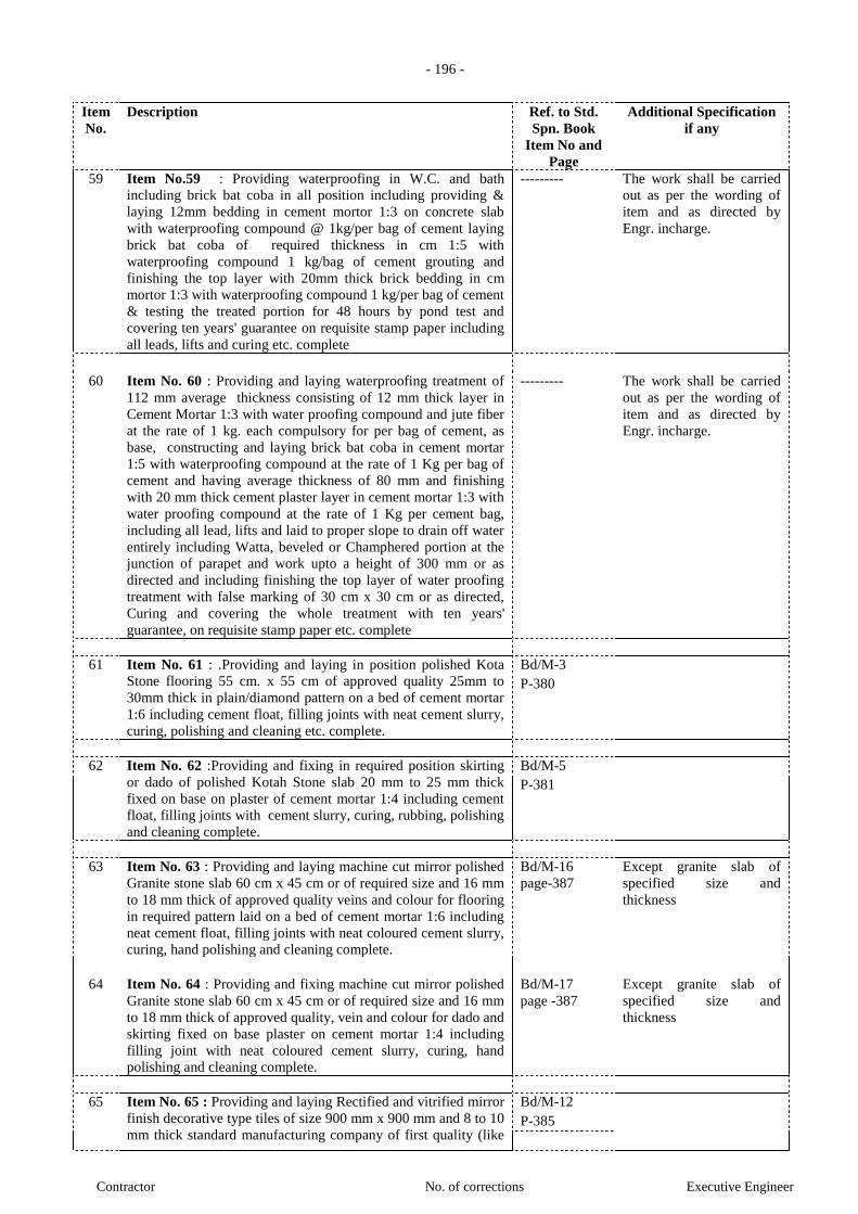
- 196 -
Contractor No. of corrections Executive Engineer
Item
No.
Description Ref. to Std.
Spn. Book
Item No and
Page
Additional Specification
if any
59 Item No.59 : Providing waterproofing in W.C. and bath
including brick bat coba in all position including providing &
laying 12mm bedding in cement mortor 1:3 on concrete slab
with waterproofing compound @ 1kg/per bag of cement laying
brick bat coba of required thickness in cm 1:5 with
waterproofing compound 1 kg/bag of cement grouting and
finishing the top layer with 20mm thick brick bedding in cm
mortor 1:3 with waterproofing compound 1 kg/per bag of cement
& testing the treated portion for 48 hours by pond test and
covering ten years' guarantee on requisite stamp paper including
all leads, lifts and curing etc. complete
--------- The work shall be carried
out as per the wording of
item and as directed by
Engr. incharge.
60 Item No. 60 : Providing and laying waterproofing treatment of
112 mm average thickness consisting of 12 mm thick layer in
Cement Mortar 1:3 with water proofing compound and jute fiber
at the rate of 1 kg. each compulsory for per bag of cement, as
base, constructing and laying brick bat coba in cement mortar
1:5 with waterproofing compound at the rate of 1 Kg per bag of
cement and having average thickness of 80 mm and finishing
with 20 mm thick cement plaster layer in cement mortar 1:3 with
water proofing compound at the rate of 1 Kg per cement bag,
including all lead, lifts and laid to proper slope to drain off water
entirely including Watta, beveled or Champhered portion at the
junction of parapet and work upto a height of 300 mm or as
directed and including finishing the top layer of water proofing
treatment with false marking of 30 cm x 30 cm or as directed,
Curing and covering the whole treatment with ten years'
guarantee, on requisite stamp paper etc. complete
--------- The work shall be carried
out as per the wording of
item and as directed by
Engr. incharge.
61 Item No. 61 : .Providing and laying in position polished Kota
Stone flooring 55 cm. x 55 cm of approved quality 25mm to
30mm thick in plain/diamond pattern on a bed of cement mortar
1:6 including cement float, filling joints with neat cement slurry,
curing, polishing and cleaning etc. complete.
Bd/M-3
P-380
62 Item No. 62 :Providing and fixing in required position skirting
or dado of polished Kotah Stone slab 20 mm to 25 mm thick
fixed on base on plaster of cement mortar 1:4 including cement
float, filling joints with cement slurry, curing, rubbing, polishing
and cleaning complete.
Bd/M-5
P-381
63 Item No. 63 : Providing and laying machine cut mirror polished
Granite stone slab 60 cm x 45 cm or of required size and 16 mm
to 18 mm thick of approved quality veins and colour for flooring
in required pattern laid on a bed of cement mortar 1:6 including
neat cement float, filling joints with neat coloured cement slurry,
curing, hand polishing and cleaning complete.
Bd/M-16
page-387
Except granite slab of
specified size and
thickness
64 Item No. 64 : Providing and fixing machine cut mirror polished
Granite stone slab 60 cm x 45 cm or of required size and 16 mm
to 18 mm thick of approved quality, vein and colour for dado and
skirting fixed on base plaster on cement mortar 1:4 including
filling joint with neat coloured cement slurry, curing, hand
polishing and cleaning complete.
Bd/M-17
page -387
Except granite slab of
specified size and
thickness
65 Item No. 65 : Providing and laying Rectified and vitrified mirror
finish decorative type tiles of size 900 mm x 900 mm and 8 to 10
mm thick standard manufacturing company of first quality (like
Bd/M-12
P-385

- 197 -
Contractor No. of corrections Executive Engineer
Item
No.
Description Ref. to Std.
Spn. Book
Item No and
Page
Additional Specification
if any
Marbonite/Porcelain) of approved make, shade and pattern for
flooring in required position laid on a bed of 1:4 cement mortar,
cement paste, filling joints with neat cement slurry, curing and
cleaning etc. complete.
66 Item No. 66 : Providing and fixing Rectified and vitrified mirror
finish decorative type tiles of size 600 mm x 600 mm and 8 to10
mm thick of approved make, shade and pattern and having water
absorption between 0.08% to 2.5% for flooring in required
position laid on plaster of 1:4 cement mortar, cement paste,
filling joints with neat cement slurry, curing and cleaning etc.
complete.
Bd/M-12
P-385
67 Item No. 67 : Providing and fixing Rectified and vitrified mirror
finish decorative type tiles of size 600 mm x 600 mm and 8 to10
mm thick of approved make, shade and pattern and having water
absorption between 0.08% to 2.5% for dado & skirting in
required position laid on plaster of 1:4 cement mortar, cement
paste, filling joints with neat cement slurry, curing and cleaning
etc. complete.
Bd/M-13
P-386
68 Item No. 68 : Providing and laying decorative ceramic tiles of
size300 mm x 300 mm and above 6 to 8 mm thick for flooring in
required position laid on bed of cement mortar 1:4 including neat
cement float, filling joints with neat cement slurry, curing and
cleaning complete.
Bd/M-12
P-385
69 Item No.69 : Providing and fixing Rectified and vitrified mirror
finish decorative type tiles of size 600 mm x 300 mm and 8 to 10
mm thick standard manufacturing company of first quality (like
Marbonite/Porcelain) of approved make, shade and pattern for
dado in required position laid on plaster of 1:4 cement mortar,
cement paste, filling joints with neat cement slurry, curing and
cleaning etc. complete.
Bd/M-13
P-386
70 Item No. 70 : .Providing and laying polished Kota stone slabs 25
to 30 mm thick for treads and risers for steps and staircase in one
piece with rounded nosing & engraving three lines for treads on
bed of 1:4 cement mortar including neat cement float, filling
joints with cement slurry, curing, polishing and cleaning etc.
complete.
Bd/M-22
P-390
71 Item No.71: .Providing and laying Granite slabs 20 mm thick of
approved quality, colour and veins, for treads and risers of steps
and staircases in one piece with round nosing & engraving three
lines for treads on bed of 1:4 cement mortar including neat
cement float, filling joints with cement slurry to match colour of
the slabs, curing, polishing and cleaning etc. complete.
Bd/M-26
P-391
72 Item No.72 : Providing sills, jambs and frames of
white/approved colour marble slabs 20 mm thick of approved
quality, vein and colour with machine polished surface on a bed
of cement mortar 1:4 including neat cement float, filling joints
with cement slurry to match the colour of the slabs, curing
polishing and rounding edges, cleaning etc. complete.
-------- The work shall be carried
out as per the wording of
item and as directed by
Engr. incharge.
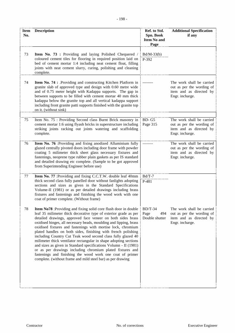
- 198 -
Contractor No. of corrections Executive Engineer
Item
No.
Description Ref. to Std.
Spn. Book
Item No and
Page
Additional Specification
if any
73 Item No. 73 : Providing and laying Polished Chequered /
coloured cement tiles for flooring in required position laid on
bed of cement mortar 1:4 including neat cement float, filling
joints with neat cement slurry, curing, polishing and cleaning
complete.
Bd/M-33(b)
P-392
74 Item No. 74 : .Providing and constructing Kitchen Platform in
granite slab of approved type and design with 0.60 metre wide
and of 0.75 meter height with Kadappa supports. The gap in
between supports to be filled with cement mortar 40 mm thick
kadappa below the granite top and all vertical kadappa support
including front granite patti supports finished with the granite top
on it. (without sink)
-------- The work shall be carried
out as per the wording of
item and as directed by
Engr. incharge.
75 Item No. 75 : Providing Second class Burnt Brick masonry in
cement mortar 1:6 using flyash bricks in superstructure including
striking joints racking out joints watering and scaffolding
complete.
BD- G5
Page 315
The work shall be carried
out as per the wording of
item and as directed by
Engr. incharge.
76 Item No. 76 :Providing and fixing anodized Alluminium fully
glazed centrally pivoted doors including door frame with powder
coating 5 milimeter thick sheet glass necessary fixtures and
fastenings, neoprene type rubber plain gaskets as per IS standard
and detailed drawing etc complete. (Sample to be got approved
from Superintending Engineer before use)
-------- The work shall be carried
out as per the wording of
item and as directed by
Engr. incharge.
77 Item No. 77 :Providing and fixing C.C.T.W. double leaf 40mm
thick second class fully panelled door without fanlights adopting
sections and sizes as given in the Standard Specifications
Volume-II (1981) or as per detailed drawings including brass
fixtures and fastenings and finishing the wood work with one
coat of primer complete. (Without frame)
Bd/T-7
P-481
78 Item No78 :Providing and fixing solid core flush door in double
leaf 35 milimeter thick decorative type of exterior grade as per
detailed drawings, approved face veneer on both sides brass
oxidised hinges, all necessary beads, moulding and lipping, brass
oxidised fixtures and fastenings with mortise lock, chromium
plated handles on both sides, finishing with french polishing
including Country Cut Teak wood second class fully glazed 40
milimeter thick ventilator rectangular in shape adopting sections
and sizes as given in Standard specifications Volumn - II (1981)
or as per drawings including chromium plated fixtures and
fastenings and finishing the wood work one coat of primer
complete. (without frame and mild steel bar) as per drawing
BD/T-34
Page 494
Double shutter
The work shall be carried
out as per the wording of
item and as directed by
Engr. incharge.

- 199 -
Contractor No. of corrections Executive Engineer
Item
No.
Description Ref. to Std.
Spn. Book
Item No and
Page
Additional Specification
if any
79 Item No. 79 :Providing and fixing solid core flush door in Single
leaf 35 milimeter thick decorative type of exterior grade as per
detailed drawings, approved face veneer on both sides brass
oxidised hinges, all necessary beads, moulding and lipping, brass
oxidised fixtures and fastenings with mortise lock, chromium
plated handles on both sides, finishing with french polishing
including Country Cut Teak wood second class fully glazed 40
milimeter thick ventilator rectangular in shape adopting sections
and sizes as given in Standard specifications Volumn - II (1981)
or as per drawings including chromium plated fixtures and
fastenings and finishing the wood work one coat of primer
complete. (without frame and mild steel bar) as per drawing
Bd/T-34
page 499
80 Item No. 80 : Providing and fixing fibre glass reinforced
polyester door shutter 30 mm thick as per IS : 14856 (2000)
(Reaffirmed 2006) without ventilator including chromium plated
fixtures and fastening with chromium plated handles on both
sides etc. complete.
-------- The work shall be carried
out as per the wording of
item and as directed by
Engr. incharge.
81 Item No. 81 :Providing and fixing false ceiling with eco-friendly
light weight calcium silicate tiles of Spintone
surface textured “Aerolite” make or equivalent of size 595 x 595
mm having 15 mm thick densified micro look edge and 100 %
humidity resistance, incombustible as per BS 476 Part IV and
thermal conductivity 0.043 w/m 0 KC and NRC 0.50 placed in
true horizontal level suspended grid of size 600x600 mm made
from hot dipped GI steel sections on Sillhouette profile, rotary
stitched double webbed white with 6mm reveal profile
(white/black), where in main “T” runner of size 42mm x 14mm
and between main tee at 600 mm centre to centre and secondary
cross “T” of Size 33x14 mm x 0.40 thick of length 600 mm long
spaced inter locked at middle of the first cross “T” in each
pannel to form grids of 1200mm x 600mm and resting on
periphery wall profile wall section 19mm (7+7) x 19mm x 0.40
thickness and laying false ceiling for services like diffusers
grills including cutting, making opening for light fitting, fixtures,
smoke detectors etc. whatever required, main tee runner to be
suspended form ceiling using G.I. soffit cleats of size 25x35x1.6
mm of required length fixed to the ceiling with 6mm dia. and
50mm long dash fastener, 4mm, dia. G.I. adjustable rods with
powder coated/good quality G.I. level adjustment clips of
35x30x08 mm spaced at 1200 ,, center to center along main tee
all complete at all heights as per specifications, drawings and as
per direction of Engineer in charge
-------- The work shall be carried
out as per the wording of
item and as directed by
Engr. incharge.
82 Item No.82:- Providing and fixing mild steel grill gate with
angle iron frame 65 x 65 x 10 mm with iron bars at 150 mm etc.
centre to centre and diagonal flats as per the detailed drawing,
including hinges, pivot blocks, locking arrangement, welding,
reveting with oil painting in three coats of approved colour shade
etc. complete. (Weight of gate 35 kg /sq.m.)
-------- The work shall be carried
out as per the wording of
item and as directed by
Engr. incharge.
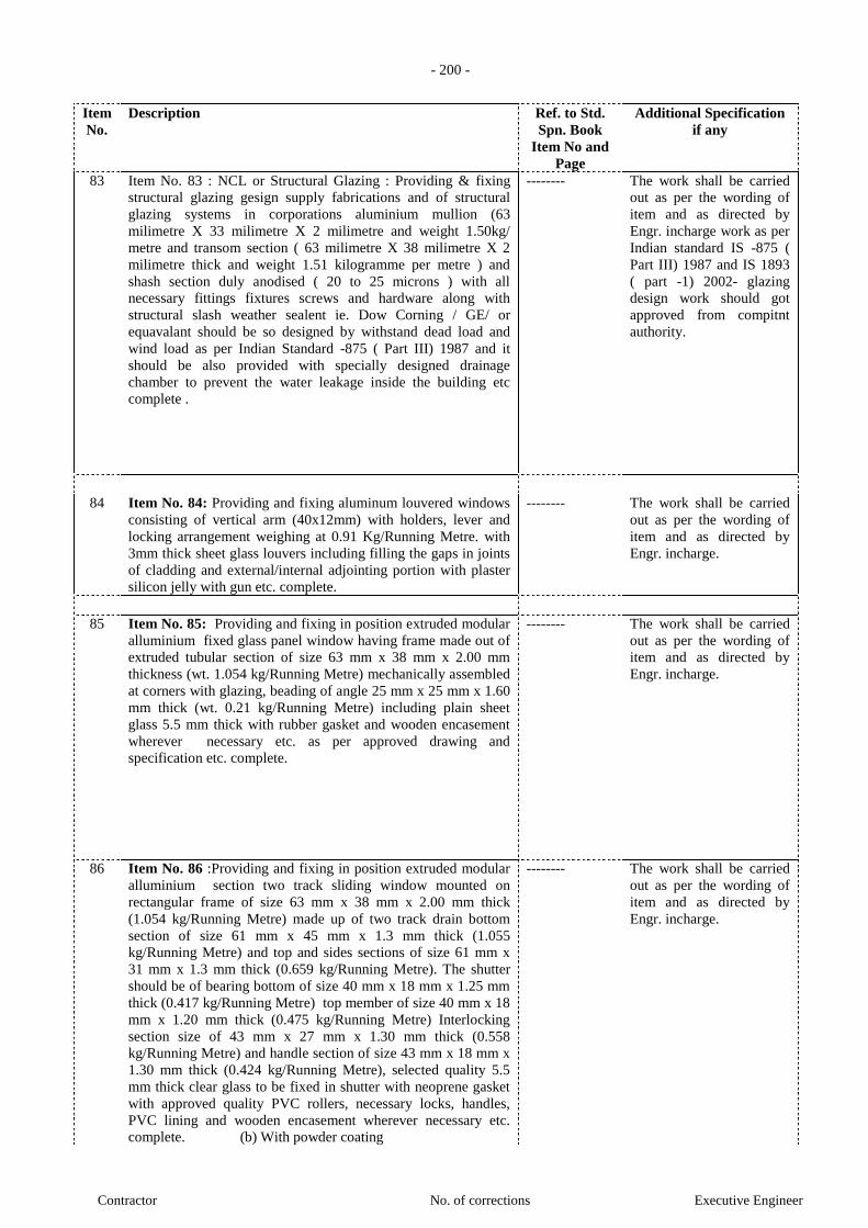
- 200 -
Contractor No. of corrections Executive Engineer
Item
No.
Description Ref. to Std.
Spn. Book
Item No and
Page
Additional Specification
if any
83 Item No. 83 : NCL or Structural Glazing : Providing & fixing
structural glazing gesign supply fabrications and of structural
glazing systems in corporations aluminium mullion (63
milimetre X 33 milimetre X 2 milimetre and weight 1.50kg/
metre and transom section ( 63 milimetre X 38 milimetre X 2
milimetre thick and weight 1.51 kilogramme per metre ) and
shash section duly anodised ( 20 to 25 microns ) with all
necessary fittings fixtures screws and hardware along with
structural slash weather sealent ie. Dow Corning / GE/ or
equavalant should be so designed by withstand dead load and
wind load as per Indian Standard -875 ( Part III) 1987 and it
should be also provided with specially designed drainage
chamber to prevent the water leakage inside the building etc
complete .
-------- The work shall be carried
out as per the wording of
item and as directed by
Engr. incharge work as per
Indian standard IS -875 (
Part III) 1987 and IS 1893
( part -1) 2002- glazing
design work should got
approved from compitnt
authority.
84 Item No. 84: Providing and fixing aluminum louvered windows
consisting of vertical arm (40x12mm) with holders, lever and
locking arrangement weighing at 0.91 Kg/Running Metre. with
3mm thick sheet glass louvers including filling the gaps in joints
of cladding and external/internal adjointing portion with plaster
silicon jelly with gun etc. complete.
-------- The work shall be carried
out as per the wording of
item and as directed by
Engr. incharge.
85 Item No. 85: Providing and fixing in position extruded modular
alluminium fixed glass panel window having frame made out of
extruded tubular section of size 63 mm x 38 mm x 2.00 mm
thickness (wt. 1.054 kg/Running Metre) mechanically assembled
at corners with glazing, beading of angle 25 mm x 25 mm x 1.60
mm thick (wt. 0.21 kg/Running Metre) including plain sheet
glass 5.5 mm thick with rubber gasket and wooden encasement
wherever necessary etc. as per approved drawing and
specification etc. complete.
-------- The work shall be carried
out as per the wording of
item and as directed by
Engr. incharge.
86 Item No. 86 :Providing and fixing in position extruded modular
alluminium section two track sliding window mounted on
rectangular frame of size 63 mm x 38 mm x 2.00 mm thick
(1.054 kg/Running Metre) made up of two track drain bottom
section of size 61 mm x 45 mm x 1.3 mm thick (1.055
kg/Running Metre) and top and sides sections of size 61 mm x
31 mm x 1.3 mm thick (0.659 kg/Running Metre). The shutter
should be of bearing bottom of size 40 mm x 18 mm x 1.25 mm
thick (0.417 kg/Running Metre) top member of size 40 mm x 18
mm x 1.20 mm thick (0.475 kg/Running Metre) Interlocking
section size of 43 mm x 27 mm x 1.30 mm thick (0.558
kg/Running Metre) and handle section of size 43 mm x 18 mm x
1.30 mm thick (0.424 kg/Running Metre), selected quality 5.5
mm thick clear glass to be fixed in shutter with neoprene gasket
with approved quality PVC rollers, necessary locks, handles,
PVC lining and wooden encasement wherever necessary etc.
complete. (b) With powder coating
-------- The work shall be carried
out as per the wording of
item and as directed by
Engr. incharge.
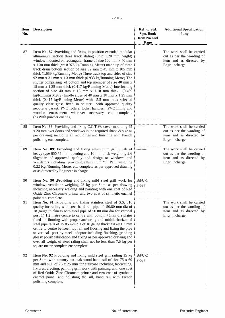
- 201 -
Contractor No. of corrections Executive Engineer
Item
No.
Description Ref. to Std.
Spn. Book
Item No and
Page
Additional Specification
if any
87 Item No. 87 :Providing and fixing in position extruded modular
alluminium section three track sliding (upto 1.20 mtr. height)
window mounted on rectangular frame of size 100 mm x 40 mm
x 1.30 mm thick (wt 0.976 kg/Running Metre) made up of three
track drain bottom section of size 92 mm x 45 mm x 105 mm
thick (1.659 kg/Running Metre) Three track top and sides of size
92 mm x 31 mm x 1.3 mm thick (0.933 kg/Running Metre) The
shutter comprising of bottom and top member of size 40 mm x
18 mm x 1.25 mm thick (0.417 kg/Running Metre) Interlocking
section of size 40 mm x 18 mm x 1.10 mm thick (0.469
kg/Running Metre) handle sides of 40 mm x 18 mm x 1.25 mm
thick (0.417 kg/Running Metre) with 5.5 mm thick selected
quality clear glass fixed in shutter with approved quality
neoprene gasket, PVC rollers, locks, handles, PVC lining and
wooden encasement wherever necessary etc. complete.
(b) With powder coating
-------- The work shall be carried
out as per the wording of
item and as directed by
Engr. incharge.
88 Item No. 88 :Providing and fixing C.C.T.W. cover moulding 45
x 20 mm over doors and windows in the required shape & size as
per drawing, including all mouldings and finishing with French
polishing etc. complete.
-------- The work shall be carried
out as per the wording of
item and as directed by
Engr. incharge.
89 Item No. 89: Providing and fixing alluminium grill / jali of
heavy type 65X75 mm opening and 10 mm thick weighting 2.6
0kg/sq.m of approved quality and design to windows and
ventilators including providing alluminium “F” Patti weighing
0.22 Kg./Running Metre. etc. complete as per approved drawing
or as directed by Engineer in charge.
-------- The work shall be carried
out as per the wording of
item and as directed by
Engr. incharge.
90 Item No. 90 :Providing and fixing mild steel grill work for
window, ventilator weighing 25 kg per Sqm. as per drawing
including necessary welding and painting with one coat of Red
Oxide Zinc Chromate primer and two coat of synthetic enamel
paint etc. complete.
Bd/U-1
P-537
91 Item No. 91 :Providing and fixing stainless steel of S.S. 316
quality for railing with steel hand rail pipe of 50,80 mm dia of
18 gauge thickness with steel pipe of 50.80 mm dia for vertical
post @ 1.2 metre centre to centre with bottom 75mm dia plates
fixed on flooring with proper anchoring and middle horizontal
steel pipe rails of 15.85 mm dia of 18 gauge thickness @ 150mm
centre to centre between top rail and flooring and fixing the pipe
to vertical post by steel adoptor including finishing, grinding
glossy polish fabrication and fixing as per approved drawing and
over all weight of steel raling shall not be less than 7.5 kg per
square meter complete.etc complete
The work shall be carried
out as per the wording of
item and as directed by
Engr. incharge.
92 Item No. 92 Providing and fixing mild steel grill railing 15 kg
per Sqm. with country cut teak wood hand rail of size 75 x 60
mm and sill of 75 x 25 mm for staircase including fabricating,
fixtures, erecting, painting grill work with painting with one coat
of Red Oxide Zinc Chromate primer and two coat of synthetic
enamel paint and polishing the sill, hand rail with French
polishing complete.
Bd/U-2
P-537
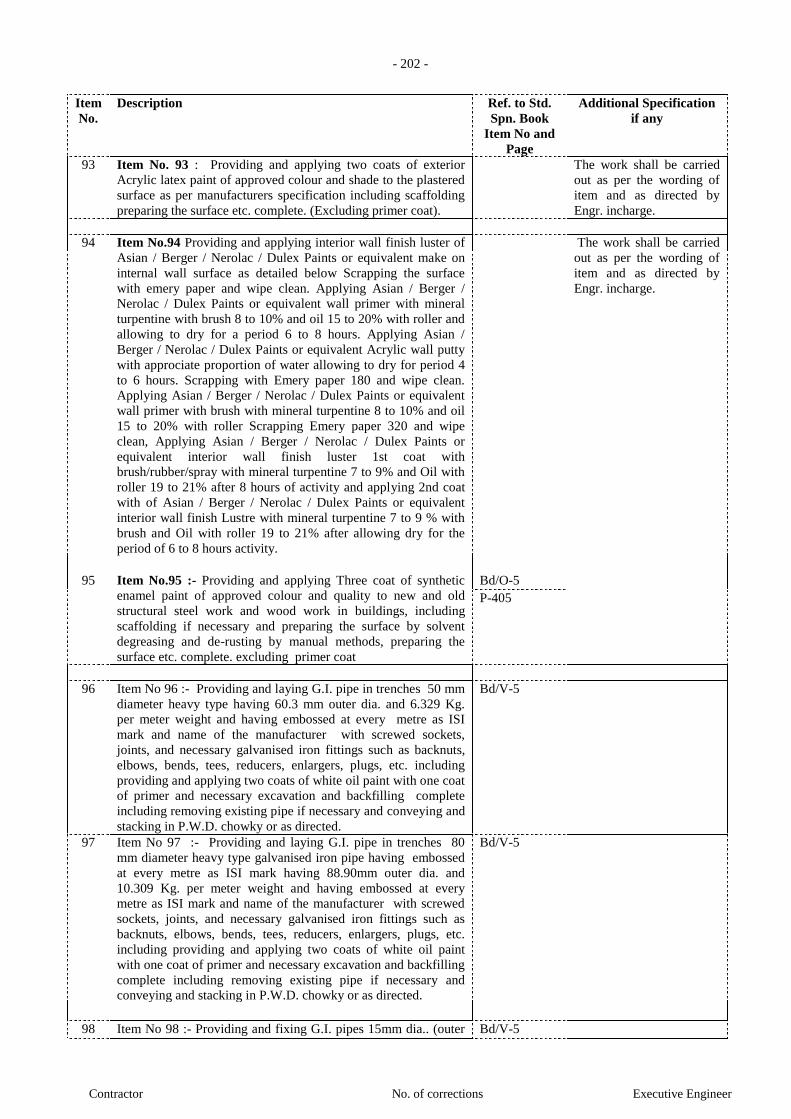
- 202 -
Contractor No. of corrections Executive Engineer
Item
No.
Description Ref. to Std.
Spn. Book
Item No and
Page
Additional Specification
if any
93 Item No. 93 : Providing and applying two coats of exterior
Acrylic latex paint of approved colour and shade to the plastered
surface as per manufacturers specification including scaffolding
preparing the surface etc. complete. (Excluding primer coat).
The work shall be carried
out as per the wording of
item and as directed by
Engr. incharge.
94 Item No.94 Providing and applying interior wall finish luster of
Asian / Berger / Nerolac / Dulex Paints or equivalent make on
internal wall surface as detailed below Scrapping the surface
with emery paper and wipe clean. Applying Asian / Berger /
Nerolac / Dulex Paints or equivalent wall primer with mineral
turpentine with brush 8 to 10% and oil 15 to 20% with roller and
allowing to dry for a period 6 to 8 hours. Applying Asian /
Berger / Nerolac / Dulex Paints or equivalent Acrylic wall putty
with approciate proportion of water allowing to dry for period 4
to 6 hours. Scrapping with Emery paper 180 and wipe clean.
Applying Asian / Berger / Nerolac / Dulex Paints or equivalent
wall primer with brush with mineral turpentine 8 to 10% and oil
15 to 20% with roller Scrapping Emery paper 320 and wipe
clean, Applying Asian / Berger / Nerolac / Dulex Paints or
equivalent interior wall finish luster 1st coat with
brush/rubber/spray with mineral turpentine 7 to 9% and Oil with
roller 19 to 21% after 8 hours of activity and applying 2nd coat
with of Asian / Berger / Nerolac / Dulex Paints or equivalent
interior wall finish Lustre with mineral turpentine 7 to 9 % with
brush and Oil with roller 19 to 21% after allowing dry for the
period of 6 to 8 hours activity.
The work shall be carried
out as per the wording of
item and as directed by
Engr. incharge.
95 Item No.95 :- Providing and applying Three coat of synthetic
enamel paint of approved colour and quality to new and old
structural steel work and wood work in buildings, including
scaffolding if necessary and preparing the surface by solvent
degreasing and de-rusting by manual methods, preparing the
surface etc. complete. excluding primer coat
Bd/O-5
P-405
96 Item No 96 :- Providing and laying G.I. pipe in trenches 50 mm
diameter heavy type having 60.3 mm outer dia. and 6.329 Kg.
per meter weight and having embossed at every metre as ISI
mark and name of the manufacturer with screwed sockets,
joints, and necessary galvanised iron fittings such as backnuts,
elbows, bends, tees, reducers, enlargers, plugs, etc. including
providing and applying two coats of white oil paint with one coat
of primer and necessary excavation and backfilling complete
including removing existing pipe if necessary and conveying and
stacking in P.W.D. chowky or as directed.
Bd/V-5
97 Item No 97 :- Providing and laying G.I. pipe in trenches 80
mm diameter heavy type galvanised iron pipe having embossed
at every metre as ISI mark having 88.90mm outer dia. and
10.309 Kg. per meter weight and having embossed at every
metre as ISI mark and name of the manufacturer with screwed
sockets, joints, and necessary galvanised iron fittings such as
backnuts, elbows, bends, tees, reducers, enlargers, plugs, etc.
including providing and applying two coats of white oil paint
with one coat of primer and necessary excavation and backfilling
complete including removing existing pipe if necessary and
conveying and stacking in P.W.D. chowky or as directed.
Bd/V-5
98 Item No 98 :- Providing and fixing G.I. pipes 15mm dia.. (outer Bd/V-5
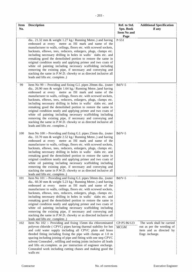
- 203 -
Contractor No. of corrections Executive Engineer
Item
No.
Description Ref. to Std.
Spn. Book
Item No and
Page
Additional Specification
if any
dia.. 21.32 mm & weight 1.27 kg./ Running Metre..) and having
embossed at every metre as ISI mark and name of the
manufacturer to walls, ceilings, floors etc. with screwed sockets,
backnuts, elbows, tees, reducers, enlargers, plugs, clamps etc.
including necessary drilling in holes in walls/ slabs etc. and
remaking good the demolished portion to restore the same in
original condition neatly and applying primer and two coats of
white oil painting including necessary scaffolding including
removing the existing pipe, if necessary and conveying and
stacking the same in P.W.D. chowky or as directed inclusive all
leads and lifts etc. complete..)
P-551
99 Item No 99 :- Providing and fixing G.I. pipes 20mm dia.. (outer
dia.. 26.90 mm & weight 1.64 kg./ Running Metre..)and having
embossed at every metre as ISI mark and name of the
manufacturer to walls, ceilings, floors etc. with screwed sockets,
backnuts, elbows, tees, reducers, enlargers, plugs, clamps etc.
including necessary drilling in holes in walls/ slabs etc. and
remaking good the demolished portion to restore the same in
original condition neatly and applying primer and two coats of
white oil painting including necessary scaffolding including
removing the existing pipe, if necessary and conveying and
stacking the same in P.W.D. chowky or as directed inclusive all
leads and lifts etc. complete..)
Bd/V-5
100 Item No 100 :- Providing and fixing G.I. pipes 25mm dia.. (outer
dia.. 33.70 mm & weight 2.52 kg./ Running Metre..) and having
embossed at every metre as ISI mark and name of the
manufacturer to walls, ceilings, floors etc. with screwed sockets,
backnuts, elbows, tees, reducers, enlargers, plugs, clamps etc.
including necessary drilling in holes in walls/ slabs etc. and
remaking good the demolished portion to restore the same in
original condition neatly and applying primer and two coats of
white oil painting including necessary scaffolding including
removing the existing pipe, if necessary and conveying and
stacking the same in P.W.D. chowky or as directed inclusive all
leads and lifts etc. complete..)
Bd/V-5
101 Item No 101 :- Providing and fixing G.I. pipes 50mm dia.. (outer
dia.. 60.30 mm & weight 5.23 kg./ Running Metre..) and having
embossed at every metre as ISI mark and name of the
manufacturer to walls, ceilings, floors etc. with screwed sockets,
backnuts, elbows, tees, reducers, enlargers, plugs, clamps etc.
including necessary drilling in holes in walls/ slabs etc. and
remaking good the demolished portion to restore the same in
original condition neatly and applying primer and two coats of
white oil painting including necessary scaffolding including
removing the existing pipe, if necessary and conveying and
stacking the same in P.W.D. chowky or as directed inclusive all
leads and lifts etc. complete..)
Bd/V-5
102 Item No 102 :- Providing and fixing 15mm dia chlorominated
polyvon chloride ( CPVC) pipes having tharmal stability for hot
and cold water supply including all CPVC plain and brass
threded fitting including fixing the pipe with clamps at 1.0 m
spacing including joining of pipe and fitting with one step CPVC
solvent Consealed , refilling and testing joints inclusive all leads
and lifts etc.complete. as per instruction of engineer encharge.
Consealed work including cutting chases and making good the
walls etc
CP-P5 86/123 The work shall be carried
out as per the wording of
item and as directed by
Engr. incharge.
MCGM
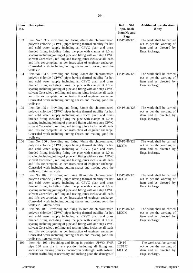
- 204 -
Contractor No. of corrections Executive Engineer
Item
No.
Description Ref. to Std.
Spn. Book
Item No and
Page
Additional Specification
if any
103 Item No 103 :- Providing and fixing 20mm dia chlorominated
polyvon chloride ( CPVC) pipes having tharmal stability for hot
and cold water supply including all CPVC plain and brass
threded fitting including fixing the pipe with clamps at 1.0 m
spacing including joining of pipe and fitting with one step CPVC
solvent Consealed , refilling and testing joints inclusive all leads
and lifts etc.complete. as per instruction of engineer encharge.
Consealed work including cutting chases and making good the
walls etc
CP-P5 86/123 The work shall be carried
out as per the wording of
item and as directed by
Engr. incharge.
104 Item No 104 :- Providing and fixing 25mm dia chlorominated
polyvon chloride ( CPVC) pipes having tharmal stability for hot
and cold water supply including all CPVC plain and brass
threded fitting including fixing the pipe with clamps at 1.0 m
spacing including joining of pipe and fitting with one step CPVC
solvent Consealed , refilling and testing joints inclusive all leads
and lifts etc.complete. as per instruction of engineer encharge.
Consealed work including cutting chases and making good the
walls etc
CP-P5 86/123 The work shall be carried
out as per the wording of
item and as directed by
Engr. incharge.
105 Item No 105 :- Providing and fixing 32mm dia chlorominated
polyvon chloride ( CPVC) pipes having tharmal stability for hot
and cold water supply including all CPVC plain and brass
threded fitting including fixing the pipe with clamps at 1.0 m
spacing including joining of pipe and fitting with one step CPVC
solvent Consealed , refilling and testing joints inclusive all leads
and lifts etc.complete. as per instruction of engineer encharge.
Consealed work including cutting chases and making good the
walls etc
CP-P5 86/123 The work shall be carried
out as per the wording of
item and as directed by
Engr. incharge.
106 Item No. 106 : Providing and fixing 40mm dia chlorominated
polyvon chloride ( CPVC) pipes having tharmal stability for hot
and cold water supply including all CPVC plain and brass
threded fitting including fixing the pipe with clamps at 1.0 m
spacing including joining of pipe and fitting with one step CPVC
solvent Consealed , refilling and testing joints inclusive all leads
and lifts etc.complete. as per instruction of engineer encharge.
Consealed work including cutting chases and making good the
walls etc. External work
CP-P5 86/123 The work shall be carried
out as per the wording of
item and as directed by
Engr. incharge.
MCGM
107 Item No. 107 : Providing and fixing 100mm dia chlorominated
polyvon chloride ( CPVC) pipes having tharmal stability for hot
and cold water supply including all CPVC plain and brass
threded fitting including fixing the pipe with clamps at 1.0 m
spacing including joining of pipe and fitting with one step CPVC
solvent Consealed , refilling and testing joints inclusive all leads
and lifts etc.complete. as per instruction of engineer encharge.
Consealed work including cutting chases and making good the
walls etc. External work
CP-P5 86/123
MCGM
The work shall be carried
out as per the wording of
item and as directed by
Engr. incharge.
108 Item No. 108 : Providing and fixing 150mm dia chlorominated
polyvon chloride ( CPVC) pipes having tharmal stability for hot
and cold water supply including all CPVC plain and brass
threded fitting including fixing the pipe with clamps at 1.0 m
spacing including joining of pipe and fitting with one step CPVC
solvent Consealed , refilling and testing joints inclusive all leads
and lifts etc.complete. as per instruction of engineer encharge.
Consealed work including cutting chases and making good the
walls etc. External work .
CP-P5 86/123
MCGM
The work shall be carried
out as per the wording of
item and as directed by
Engr. incharge.
109 Item No. 109 : Providing and fixing in position UPVC/ SWR
pipe 160 mm dia in any position including all fitting and
accessories making joints / connection watertight with solvent
cement scaffolding if necessary and making good the damages if
CP-P5
202/152
MCGM
The work shall be carried
out as per the wording of
item and as directed by
Engr. incharge.

- 205 -
Contractor No. of corrections Executive Engineer
Item
No.
Description Ref. to Std.
Spn. Book
Item No and
Page
Additional Specification
if any
necessary ( Excluding excavation and refilling treanches)
etc.complete as specified and directed ( no separate payment
shall be mede for fittings and accessaries .
110 Item No. 110 :Providing and laying 225mm Dia. Salt Glazed
Stoneware pipe including fittings such as bends, tees, single
junctions, double junctions, laying, jointing (excluding
excavation and refilling the trenches) etc. complete as directed.
Bd/V-39
P-573
111 Item No. 111 :Providing and fixing P.V.C. Rain Water Pipes
110mm dia and having wall thickness of 2.2 to 2.7 mm
conforming to I.S. 13592-1992 including proper rain water
receiving recess with P.V.C. plug bend, necessary fittings such
as offsets, shoes including fixing the pipe on wall using approved
wooden cleats projecting 25 mm to 40 mm from face of wall &
fixing with clips of approved quality & number, filling the joints
using rubber gasket with solvent cement and properly resting the
shoe of pipes on C.C. or masonry blocks, including necessary
scaffolding, and maintenance for 3 years for any leakages or
dislocation of pipes. All the PVC fittings and additional two
piece socket clips shall be got approved from Engineer in charge
etc. complete. (The contractors shall give 3 years guarantee bond
for payment)
Bd/V-33
P-575
112 Item No.112:Providing and fixing P.V.C. Soil/Waste water Pipes
110mm dia and having wall thickness of 3.2 to 3.8 mm
conforming to I.S. 13592-1992 including P.V.C. plug bend,
necessary fittings such as bend, tees, single junction, double
junction, slotted vent offsets on walls or in the ground including
fixing the pipe on wall using approved wooden cleats projecting
25 mm to 40 mm from face of wall and fixing with clips of
approved quality and number, filling the joints using rubber
gasket with solvent cement including necessary scaffolding, and
maintenance for 3 years for any leakages or dislocation of pipes.
All the PVC fittings and additional two piece socket clips shall
be got approved from Engineer in charge etc. complete. (The
contractors shall give 3 years guarantee bond for payment)
Bd/V-35
P-570
113 Item No. 113:Providing & fixing in position UPVC, Ultra Voilet
stabilised 90 mm outer diameter cowl dome confirming I.S. 4985
including making joints with solvent / cement etc. complete.
The work shall be carried
out as per the wording of
item and as directed by
Engr. incharge.
114 Item No. 114:Providing and fixing heavy type 12mm. Diameter
screw down bib/stop tap of brass of approved quality and make,
including necessary sockets, union nut, testing etc. complete.
Bd/V-8
P-554
115 Item No. 115:Providing and fixing stealth faucet bib cock with
flange of approved jaguar or equivalent make including
necessary socket / union nut etc complete.
The work shall be carried
out as per the wording of
item and as directed by
Engr. incharge.
116 Item No. 116: Providing and fixing soap dispenser with glass
bottle of approved jaguar or equivalent make etc complete.
The work shall be carried
out as per the wording of
item and as directed by
Engr. incharge.

- 206 -
Contractor No. of corrections Executive Engineer
Item
No.
Description Ref. to Std.
Spn. Book
Item No and
Page
Additional Specification
if any
117 Item No. 117:Providing and fixing Towel ring round flange of
approved jaguar or equivalent make etc complete.
The work shall be carried
out as per the wording of
item and as directed by
Engr. incharge.
118 Item No. 118:Providing and fixing steath faucet Toilet roll
Holder with flab of approved jaguar or equivalent make etc
complete.
The work shall be carried
out as per the wording of
item and as directed by
Engr. incharge.
119 Item No. 119 :Providing and fixing 25 mm.dia screw down
wheeled stop tap of steel with chromium plating of approved
quality and make bearing I.S.I. mark, including sockets, union
nut complete.
Bd/V-9
P-555
120 Item No. 120 :Providing and fixing 50mm.dia screw down
wheeled stop tap of steel with chromium plating of approved
quality and make bearing I.S.I. mark, including sockets, union
nut complete.
Bd/V-9
P-555
121 Item No. 121 :Providing and fixing 80mm.dia screw down
wheeled stop tap of steel with chromium plating of approved
quality and make bearing I.S.I. mark, including sockets, union
nut complete.
Bd/V-9
P-555
122 Item No. 122:Providing and fixing fittings and accessories such
as ball cock, overflow pipe with mosquito proof coupling, scour,
pipe with plug, manhole with cover and locking arrangement,
connecting pipes and embedding intake and outflow pipes into
the R.C.C water reservior etc. complete.
The work shall be carried
out as per the wording of
item and as directed by
Engr. incharge.
123 Item No.123:Providing and fixing Orrisa type white glazed
earthenware 580 mm x 450 mm water closet pan including trap,
cast iron soil and vent pipes upto the outside face of the wall
including 100 mm. diameter cast iron plug bend, cement
concrete bedding, 10 litres capacity H.D.P.E. flushing cistern
with fittings, inlet pipe with stop tap, brackets, 32 mm. diameter
galvanised iron heavy type flush pipe with fittings and clamps,
painting to exposed pipes and cutting and making good the walls
and floors etc. complete. (Excluding water proofing with brick
bat coba)
Bd/V-20
P-559
124 Item No. 124 :Providing and fixing European type coloured
glazed earthenware 580mm coupled closet syphonic trap with
syphonic low level white glazed 10 litres cistern with black
bakelite seat and lid with chromium plated brass hinges
including cast iron soil and vent pipes upto the outside face of
the wall including 100 mm diameter cast iron plug bend, inlet
pipe, stop tap etc. all fittings, cutting and making good walls and
floors complete.
Bd/V-22
P-562
125 Item No. 125: Providing and fixing White glazed earthenware
........ type urinal with white H.D.P.E. flushing cistern of 5 litres
capacity with fittings, inlet pipe and stop tap, brackets for fixing
the cistern, 32 mm diameter galvanised iron heavy type flush
pipe with fittings and spreader arrangement etc. complete.
Bd/V-25 The work shall be carried
out as per the wording of
item and as directed by
Engr. incharge.
P-563
126 Item No.126 Providing and fixing white glazed earthenware Bd/HES-21 The work shall be carried
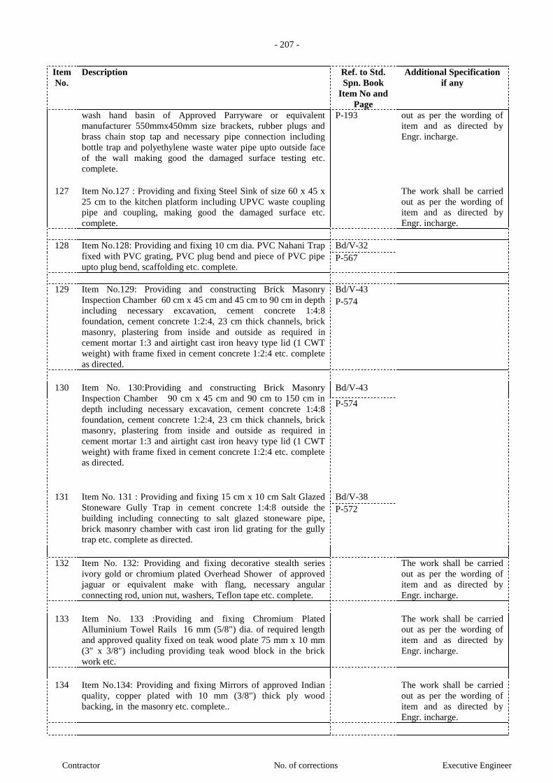
- 207 -
Contractor No. of corrections Executive Engineer
Item
No.
Description Ref. to Std.
Spn. Book
Item No and
Page
Additional Specification
if any
wash hand basin of Approved Parryware or equivalent
manufacturer 550mmx450mm size brackets, rubber plugs and
brass chain stop tap and necessary pipe connection including
bottle trap and polyethylene waste water pipe upto outside face
of the wall making good the damaged surface testing etc.
complete.
P-193 out as per the wording of
item and as directed by
Engr. incharge.
127 Item No.127 : Providing and fixing Steel Sink of size 60 x 45 x
25 cm to the kitchen platform including UPVC waste coupling
pipe and coupling, making good the damaged surface etc.
complete.
The work shall be carried
out as per the wording of
item and as directed by
Engr. incharge.
128 Item No.128: Providing and fixing 10 cm dia. PVC Nahani Trap
fixed with PVC grating, PVC plug bend and piece of PVC pipe
upto plug bend, scaffolding etc. complete.
Bd/V-32
P-567
129 Item No.129: Providing and constructing Brick Masonry
Inspection Chamber 60 cm x 45 cm and 45 cm to 90 cm in depth
including necessary excavation, cement concrete 1:4:8
foundation, cement concrete 1:2:4, 23 cm thick channels, brick
masonry, plastering from inside and outside as required in
cement mortar 1:3 and airtight cast iron heavy type lid (1 CWT
weight) with frame fixed in cement concrete 1:2:4 etc. complete
as directed.
Bd/V-43
P-574
130 Item No. 130:Providing and constructing Brick Masonry
Inspection Chamber 90 cm x 45 cm and 90 cm to 150 cm in
depth including necessary excavation, cement concrete 1:4:8
foundation, cement concrete 1:2:4, 23 cm thick channels, brick
masonry, plastering from inside and outside as required in
cement mortar 1:3 and airtight cast iron heavy type lid (1 CWT
weight) with frame fixed in cement concrete 1:2:4 etc. complete
as directed.
Bd/V-43
P-574
131 Item No. 131 : Providing and fixing 15 cm x 10 cm Salt Glazed
Stoneware Gully Trap in cement concrete 1:4:8 outside the
building including connecting to salt glazed stoneware pipe,
brick masonry chamber with cast iron lid grating for the gully
trap etc. complete as directed.
Bd/V-38
P-572
132 Item No. 132: Providing and fixing decorative stealth series
ivory gold or chromium plated Overhead Shower of approved
jaguar or equivalent make with flang, necessary angular
connecting rod, union nut, washers, Teflon tape etc. complete.
The work shall be carried
out as per the wording of
item and as directed by
Engr. incharge.
133 Item No. 133 :Providing and fixing Chromium Plated
Alluminium Towel Rails 16 mm (5/8") dia. of required length
and approved quality fixed on teak wood plate 75 mm x 10 mm
(3" x 3/8") including providing teak wood block in the brick
work etc.
The work shall be carried
out as per the wording of
item and as directed by
Engr. incharge.
134 Item No.134: Providing and fixing Mirrors of approved Indian
quality, copper plated with 10 mm (3/8") thick ply wood
backing, in the masonry etc. complete..
The work shall be carried
out as per the wording of
item and as directed by
Engr. incharge.
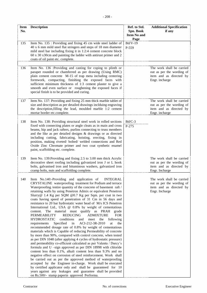
- 208 -
Contractor No. of corrections Executive Engineer
Item
No.
Description Ref. to Std.
Spn. Book
Item No and
Page
Additional Specification
if any
135 Item No. 135 : Providing and fixing 45 cm wide steel ladder of
40 x 6 mm mild steel flat stringers and steps of 18 mm diameter
mild steel bar including fixing it in 1:2:4 cement concrete block
60 x 30 x30cm and painting the ladder with antirust primer and 2
coats of oil paint etc. complete.
Bd/V-19
P-559
136 Item No. 136 :Providing and casting for coping to plinth or
parapet rounded or chamferred as per drawing (Using RMC)
plain cement concrete M-15 of trap meta including centering
formwork, compacting, finishing the exposed faces with
sufficient minimum thickness of 1:3 cement plaster to give a
smooth and even surface or roughening the exposed faces if
special finish is to be provided and curing.
The work shall be carried
out as per the wording of
item and as directed by
Engr. incharge
137 Item No. 137: Providing and fixing 25 mm thick marble tablet of
size and description as per detailed drawings inclduing engraving
the description,filling the lead, moulded marble 1:2 cement
mortar border etc.complete.
The work shall be carried
out as per the wording of
item and as directed by
Engr. incharge
138 Item No. 138: Providing structural steel work in rolled sections
fixed with connecting plates or angle cleats as in main and cross
beams, hip and jack rafters, purlins connecting to truss members
and the like as per detailed designs & drawings or as directed
including cutting, fabricating, hoisting, erecting, fixing in
position, making riveted/ bolted/ welded connections and Red
Oxide Zinc Chromate primer and two coat synthetic enamel
paint, scaffolding etc. complete.
Bd/C-3
P-275
139 Item No. 139:Providing and fixing 2.5 to 3.00 mm thick Acrylic
decorative sheet roofing including galvanized iron J or L hook
bolts, galvanised iron and bituminous washers, galvanized iron
cramp bolts, nuts and scaffolding complete.
The work shall be carried
out as per the wording of
item and as directed by
Engr. Incharge
140 Item No.140:-Providing and application of INTEGRAL
CRYSTALINE waterproofing treatment for Podium and terrace
Waterproofing /entire quantity of the concrete of basement raft /
retaining walls by using Penetron Admix or equivalent Penetron
Slurry@ 1.4 Kg per SQM @0.7 Kg per Sqm. per coat in two
coats having speed of penetration of 31 Cm in 56 days and
resistance to 20 bar hydrostatic water head of M/s ICS Penetron
International Ltd., USA @ 0.8% by weight of cementatious
content. The material must qualify as PRAH grade
PERMEABILITY REDUCING ADMIXTURE FOR
HYDROSTATIC conditions and meet the following
requirements Specified in ACI-212-3R-2010 at the
recommended dosage rate of 0.8% by weight of cementatious
materials which is Capable of reducing Permeability of concrete
by more than 90%, compared with control concrete, when tested
as per DIN 1048 (after applying 4 cycles of hydrostatic pressure)
and permeability co-efficient calculated as per Valenta / Darcy’s
formula and U –sign approved as per DIN 18998 with chloride
content less than 0.1%, alkali content less than 9.3% and no
negative effect on corrosion of steel reinforcement. Work shall
be carried out as per the approved method of waterproofing
accepted by the Engineer in-charge. Work shall be executed
by certified applicator only and shall be guaranteed for 10
years against any leakages and guarantee shall be provided
on Rs.500/- stamp paperin approved Performa.
The work shall be carried
out as per the wording of
item and as directed by
Engr. Incharge

- 209 -
Contractor No. of corrections Executive Engineer
Item
No.
Description Ref. to Std.
Spn. Book
Item No and
Page
Additional Specification
if any
141 Item No.141:- Providing and application of waterproofing from
outside basement lift pits and other underground structures
....Work shall be executed by certified applicator only and shall
be guaranteed for 10 years against any leakages and
guarantee shall be provided on Rs.500/- stamp paper in
approved Performa.
CS-WP/
33/40 MCGM
The work shall be carried
out as per the wording of
item and as directed by
Engr. Incharge
142 Item No.142:- Removing any kind of debris including loading in
truck and conveying to dumping point approved by BMC,
unloading, spreading etc. complete. With all leads and lifts.
Rates should beused only when transportation upto 40 km only
Necessary
permission
from MCGM
should be
taken by
contractor
The work shall be carried
out as per the wording of
item and as directed by
Engr. Incharge
143 Item No.143:- Providing and fixing chicken wire mesh
(Reference IS : 3150 - 1982) of 19 size of aperture at the
junction of R.C.C. members and brick work of approved quality
including fixing mesh in position by necessary nailing in
concrete or / B.B. masonry and or tying by binding wire etc.
complete
The work shall be carried
out as per the wording of
item and as directed by
Engr. Incharge
144 Item No.144:- Providing and fixing hydraulic door closer of
approved quality and make to door shutter including making
proper adjustment for smooth operation etc. complete.
The work shall be carried
out as per the wording of
item and as directed by
Engr. Incharge
145 Item No.145:- Providing rain water harvesting by constructing
brickmasonry collection chamber 60 X 60 Cm size and 90 Cm
depth and plastering on side of walls, Cc copong 10mm thickand
RCC cover with frame of size 90 X45 Cm 2Nos including
providing 120 X 120 Cm size filter media of 30Cm thick 6mm
grit layer, 30 m thick 12 mm crush metal layer, 30 Cm 20 mm
crushed metal layerand 30 Cm thick 40 mm crushed metal layer
and necessary excavation and refilling etc complete.
The work shall be carried
out as per the wording of
item and as directed by
Engr. Incharge
146 Item No. 146 : Providing and erecting two legged mild steel
tubular scaffolding, of width 1200 to 1500 mm largely free
standing, using H frames or mild steel tubular pipes of minimum
40 mm diameter, with base plates, fixed or adjustable with
necessary clamps, couplers, brackets for projections, joints pins,
pullies and other accessories, including steel angle or tubular
pipe bracings at adequate intervals, access platforms of metal or
timber planks of span not exceeding 2.5 meters, including access
ladders with intermediate platforms. The scaffolding is to be
suitably braced and anchored to the building using support
systems created temporarily at the openings in the walls using
vertical and horizontal details on the entire building face,
required, and safety platforms at ground level covering the
entrances to the building. Item includes Providing and erecting
Nylon Net covering fixed to the exterior face of scaffolding
The work shall be carried
out as per the wording of
item and as directed by
Engr. Incharge
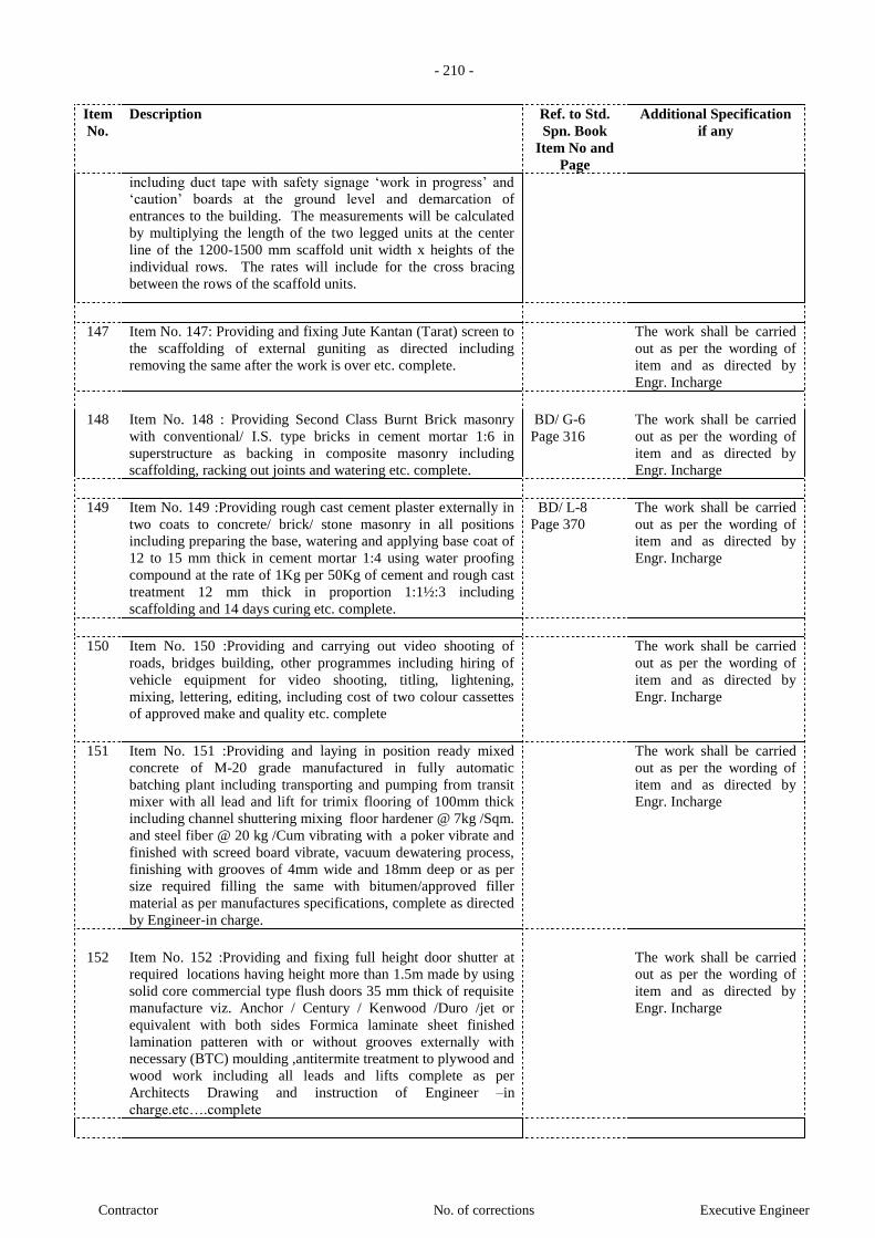
- 210 -
Contractor No. of corrections Executive Engineer
Item
No.
Description Ref. to Std.
Spn. Book
Item No and
Page
Additional Specification
if any
including duct tape with safety signage ‘work in progress’ and
‘caution’ boards at the ground level and demarcation of
entrances to the building. The measurements will be calculated
by multiplying the length of the two legged units at the center
line of the 1200-1500 mm scaffold unit width x heights of the
individual rows. The rates will include for the cross bracing
between the rows of the scaffold units.
147 Item No. 147: Providing and fixing Jute Kantan (Tarat) screen to
the scaffolding of external guniting as directed including
removing the same after the work is over etc. complete.
The work shall be carried
out as per the wording of
item and as directed by
Engr. Incharge
148 Item No. 148 : Providing Second Class Burnt Brick masonry
with conventional/ I.S. type bricks in cement mortar 1:6 in
superstructure as backing in composite masonry including
scaffolding, racking out joints and watering etc. complete.
BD/ G-6
Page 316
The work shall be carried
out as per the wording of
item and as directed by
Engr. Incharge
149 Item No. 149 :Providing rough cast cement plaster externally in
two coats to concrete/ brick/ stone masonry in all positions
including preparing the base, watering and applying base coat of
12 to 15 mm thick in cement mortar 1:4 using water proofing
compound at the rate of 1Kg per 50Kg of cement and rough cast
treatment 12 mm thick in proportion 1:1½:3 including
scaffolding and 14 days curing etc. complete.
BD/ L-8
Page 370
The work shall be carried
out as per the wording of
item and as directed by
Engr. Incharge
150 Item No. 150 :Providing and carrying out video shooting of
roads, bridges building, other programmes including hiring of
vehicle equipment for video shooting, titling, lightening,
mixing, lettering, editing, including cost of two colour cassettes
of approved make and quality etc. complete
The work shall be carried
out as per the wording of
item and as directed by
Engr. Incharge
151 Item No. 151 :Providing and laying in position ready mixed
concrete of M-20 grade manufactured in fully automatic
batching plant including transporting and pumping from transit
mixer with all lead and lift for trimix flooring of 100mm thick
including channel shuttering mixing floor hardener @ 7kg /Sqm.
and steel fiber @ 20 kg /Cum vibrating with a poker vibrate and
finished with screed board vibrate, vacuum dewatering process,
finishing with grooves of 4mm wide and 18mm deep or as per
size required filling the same with bitumen/approved filler
material as per manufactures specifications, complete as directed
by Engineer-in charge.
The work shall be carried
out as per the wording of
item and as directed by
Engr. Incharge
152 Item No. 152 :Providing and fixing full height door shutter at
required locations having height more than 1.5m made by using
solid core commercial type flush doors 35 mm thick of requisite
manufacture viz. Anchor / Century / Kenwood /Duro /jet or
equivalent with both sides Formica laminate sheet finished
lamination patteren with or without grooves externally with
necessary (BTC) moulding ,antitermite treatment to plywood and
wood work including all leads and lifts complete as per
Architects Drawing and instruction of Engineer –in
charge.etc….complete
The work shall be carried
out as per the wording of
item and as directed by
Engr. Incharge
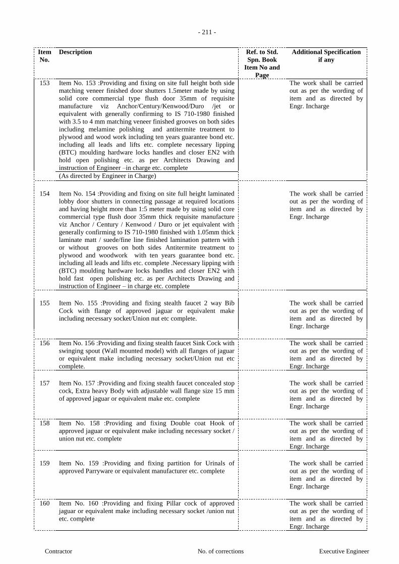
- 211 -
Contractor No. of corrections Executive Engineer
Item
No.
Description Ref. to Std.
Spn. Book
Item No and
Page
Additional Specification
if any
153 Item No. 153 :Providing and fixing on site full height both side
matching veneer finished door shutters 1.5meter made by using
solid core commercial type flush door 35mm of requisite
manufacture viz Anchor/Century/Kenwood/Duro /jet or
equivalent with generally confirming to IS 710-1980 finished
with 3.5 to 4 mm matching veneer finished grooves on both sides
including melamine polishing and antitermite treatment to
plywood and wood work including ten years guarantee bond etc.
including all leads and lifts etc. complete necessary lipping
(BTC) moulding hardware locks handles and closer EN2 with
hold open polishing etc. as per Architects Drawing and
instruction of Engineer –in charge etc. complete
The work shall be carried
out as per the wording of
item and as directed by
Engr. Incharge
(As directed by Engineer in Charge)
154 Item No. 154 :Providing and fixing on site full height laminated
lobby door shutters in connecting passage at required locations
and having height more than 1:5 meter made by using solid core
commercial type flush door 35mm thick requisite manufacture
viz Anchor / Century / Kenwood / Duro or jet equivalent with
generally confirming to IS 710-1980 finished with 1.05mm thick
laminate matt / suede/fine line finished lamination pattern with
or without grooves on both sides Antitermite treatment to
plywood and woodwork with ten years guarantee bond etc.
including all leads and lifts etc. complete .Necessary lipping with
(BTC) moulding hardware locks handles and closer EN2 with
hold fast open polishing etc. as per Architects Drawing and
instruction of Engineer – in charge etc. complete
The work shall be carried
out as per the wording of
item and as directed by
Engr. Incharge
155 Item No. 155 :Providing and fixing stealth faucet 2 way Bib
Cock with flange of approved jaguar or equivalent make
including necessary socket/Union nut etc complete.
The work shall be carried
out as per the wording of
item and as directed by
Engr. Incharge
156 Item No. 156 :Providing and fixing stealth faucet Sink Cock with
swinging spout (Wall mounted model) with all flanges of jaguar
or equivalent make including necessary socket/Union nut etc
complete.
The work shall be carried
out as per the wording of
item and as directed by
Engr. Incharge
157 Item No. 157 :Providing and fixing stealth faucet concealed stop
cock, Extra heavy Body with adjustable wall flange size 15 mm
of approved jaguar or equivalent make etc. complete
The work shall be carried
out as per the wording of
item and as directed by
Engr. Incharge
158 Item No. 158 :Providing and fixing Double coat Hook of
approved jaguar or equivalent make including necessary socket /
union nut etc. complete
The work shall be carried
out as per the wording of
item and as directed by
Engr. Incharge
159 Item No. 159 :Providing and fixing partition for Urinals of
approved Parryware or equivalent manufacturer etc. complete
The work shall be carried
out as per the wording of
item and as directed by
Engr. Incharge
160 Item No. 160 :Providing and fixing Pillar cock of approved
jaguar or equivalent make including necessary socket /union nut
etc. complete
The work shall be carried
out as per the wording of
item and as directed by
Engr. Incharge
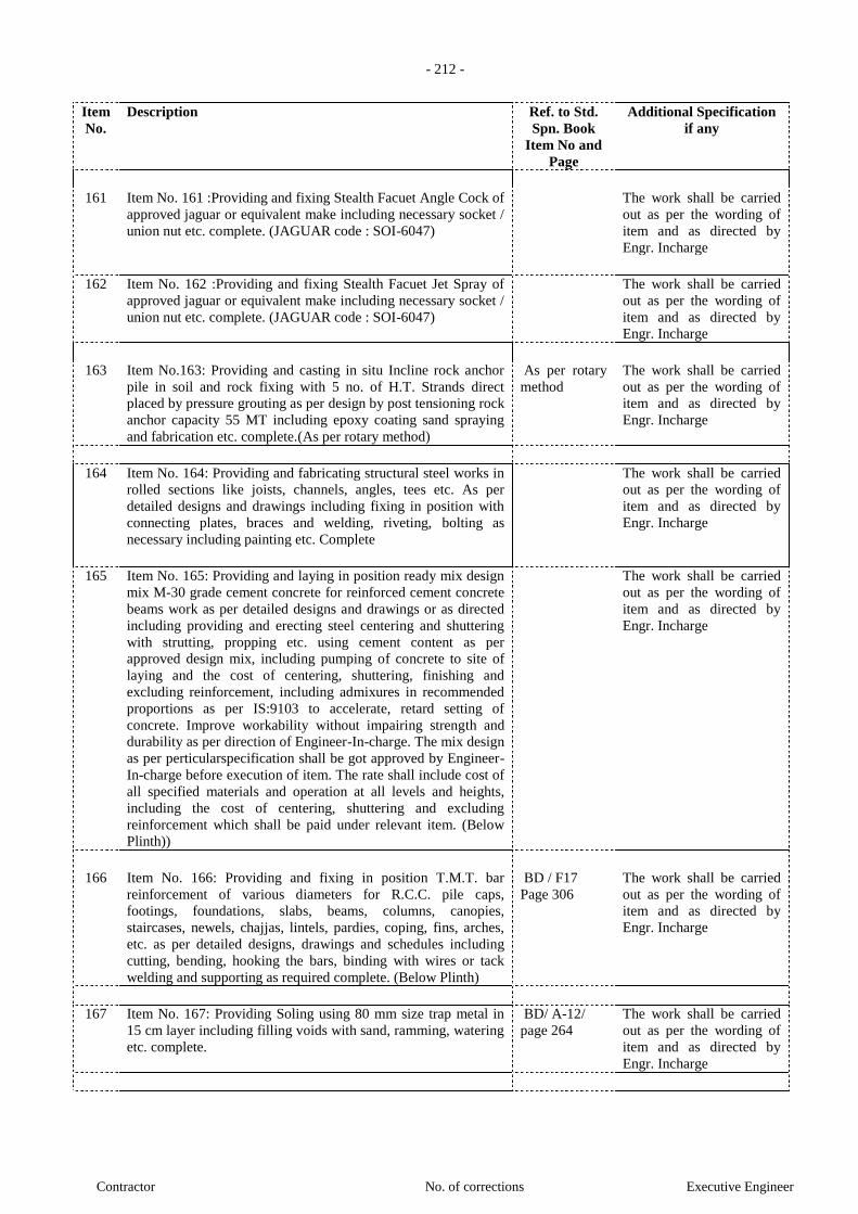
- 212 -
Contractor No. of corrections Executive Engineer
Item
No.
Description Ref. to Std.
Spn. Book
Item No and
Page
Additional Specification
if any
161 Item No. 161 :Providing and fixing Stealth Facuet Angle Cock of
approved jaguar or equivalent make including necessary socket /
union nut etc. complete. (JAGUAR code : SOI-6047)
The work shall be carried
out as per the wording of
item and as directed by
Engr. Incharge
162 Item No. 162 :Providing and fixing Stealth Facuet Jet Spray of
approved jaguar or equivalent make including necessary socket /
union nut etc. complete. (JAGUAR code : SOI-6047)
The work shall be carried
out as per the wording of
item and as directed by
Engr. Incharge
163 Item No.163: Providing and casting in situ Incline rock anchor
pile in soil and rock fixing with 5 no. of H.T. Strands direct
placed by pressure grouting as per design by post tensioning rock
anchor capacity 55 MT including epoxy coating sand spraying
and fabrication etc. complete.(As per rotary method)
As per rotary
method
The work shall be carried
out as per the wording of
item and as directed by
Engr. Incharge
164 Item No. 164: Providing and fabricating structural steel works in
rolled sections like joists, channels, angles, tees etc. As per
detailed designs and drawings including fixing in position with
connecting plates, braces and welding, riveting, bolting as
necessary including painting etc. Complete
The work shall be carried
out as per the wording of
item and as directed by
Engr. Incharge
165 Item No. 165: Providing and laying in position ready mix design
mix M-30 grade cement concrete for reinforced cement concrete
beams work as per detailed designs and drawings or as directed
including providing and erecting steel centering and shuttering
with strutting, propping etc. using cement content as per
approved design mix, including pumping of concrete to site of
laying and the cost of centering, shuttering, finishing and
excluding reinforcement, including admixures in recommended
proportions as per IS:9103 to accelerate, retard setting of
concrete. Improve workability without impairing strength and
durability as per direction of Engineer-In-charge. The mix design
as per perticularspecification shall be got approved by Engineer-
In-charge before execution of item. The rate shall include cost of
all specified materials and operation at all levels and heights,
including the cost of centering, shuttering and excluding
reinforcement which shall be paid under relevant item. (Below
Plinth))
The work shall be carried
out as per the wording of
item and as directed by
Engr. Incharge
166 Item No. 166: Providing and fixing in position T.M.T. bar
reinforcement of various diameters for R.C.C. pile caps,
footings, foundations, slabs, beams, columns, canopies,
staircases, newels, chajjas, lintels, pardies, coping, fins, arches,
etc. as per detailed designs, drawings and schedules including
cutting, bending, hooking the bars, binding with wires or tack
welding and supporting as required complete. (Below Plinth)
BD / F17
Page 306
The work shall be carried
out as per the wording of
item and as directed by
Engr. Incharge
167 Item No. 167: Providing Soling using 80 mm size trap metal in
15 cm layer including filling voids with sand, ramming, watering
etc. complete.
BD/ A-12/
page 264
The work shall be carried
out as per the wording of
item and as directed by
Engr. Incharge
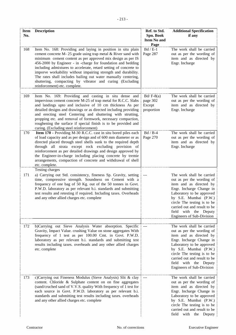
- 213 -
Contractor No. of corrections Executive Engineer
Item
No.
Description Ref. to Std.
Spn. Book
Item No and
Page
Additional Specification
if any
168 Item No. 168: Providing and laying in position in situ plain
cement concrete M- 25 grade using trap metal & River sand with
minimum cement content as per approved mix design as per IS
456-2000 by Engineer - in -charge for foundation and bedding
including admixtures to accelerate, retard setting of concrete to
imporve workability without impairing strength and durability.
The rates shall includes bailing out water manually centering,
shuttering, compacting by vibrator and curing (Excluding
reinforcement) etc. complete.
Bd / E-1
Page 287
The work shall be carried
out as per the wording of
item and as directed by
Engr. Incharge
169 Item No. 169: Providing and casting in situ dense and
impervious cement concrete M-25 of trap metal for R.C.C. Slabs
and landings upto and inclusive of 10 cm thickness As per
detailed designs and drawings or as directed including providing
and erecting steel Centering and shuttering with strutting,
propping etc. and removal of formwork, necessary compaction,
roughening the surface if special finish is to be provided and
curing. (Excluding steel reinforcement)
Bd/ F-8(a)
page 302
Except
proportion
The work shall be carried
out as per the wording of
item and as directed by
Engr. Incharge
170 Item 170 - Providing M-30 R.C.C. cast in situ bored piles each
of load capacity and as per design and of 600 mm diameter or as
directed placed through steel shells sunk to the required depth
through all strata except rock excluding provision of
reinforcement as per detailed drawings and design approved by
the Engineer-in-charge including placing concrete by tremie
arrangements, compaction of concrete and withdrawal of shell
etc. complete.
Bd / B-4
Page 270
The work shall be carried
out as per the wording of
item and as directed by
Engr. Incharge
Testing charges
171 a) Carrying out Std. consistency, fineness Sp. Gravity, setting
time, compressive strength. Soundness on Cement with a
frequency of one bag of 50 Kg. out of the 50 tonnes in Govt.
P.W.D. laboratory as per relevant b.i. standards and submitting
test results and retesting if required. Including taxes. Overheads
and any other allied charges etc. complete
--- The work shall be carried
out as per the wording of
item and as directed by
Engr. Incharge Change in
Laboratory to be approved
by S.E. Mumbai (P.W.)
circle The testing is to be
carried out and result to be
field with the Deputy
Engineers of Sub-Division
172 b)Carrying out Sieve Analysis Water absorption. Specific
Gravity, Impact Value. crushing Value on stone aggregates With
frequency of 1 test as per 100.00 Cmt. in Govt. P.W.D.
laboratory as per relevant b.i. standards and submitting test
results including taxes. overheads and any other allied charges
etc. complete
--- The work shall be carried
out as per the wording of
item and as directed by
Engr. Incharge Change in
Laboratory to be approved
by S.E. Mumbai (P.W.)
circle The testing is to be
carried out and result to be
field with the Deputy
Engineers of Sub-Division
173 c)Carrying out Fineness Modulus (Sieve Analysis) Slit & clay
content. Chloride & Sulphate content on on fine aggregates
(sand/cruched sand of V.V.S. quality With frequency of 1 test for
each source in Govt. P.W.D. laboratory as per relevant b.i.
standards and submitting test results including taxes. overheads
and any other allied charges etc. complete
--- The work shall be carried
out as per the wording of
item and as directed by
Engr. Incharge Change in
Laboratory to be approved
by S.E. Mumbai (P.W.)
circle The testing is to be
carried out and result to be
field with the Deputy

- 214 -
Contractor No. of corrections Executive Engineer
Item
No.
Description Ref. to Std.
Spn. Book
Item No and
Page
Additional Specification
if any
Engineers of Sub-Division
174 d) Carrying out Water absorption. Compressive Strength,
Efflorescence test on Brick With frequency of 1 test (set of 5
bricks) for quality of 50,000 Brick in Govt. P.W.D. laboratory as
per relevant b.i. standards and submitting test results including
taxes. overheads and any other allied charges etc. complete
--- The work shall be carried
out as per the wording of
item and as directed by
Engr. Incharge Change in
Laboratory to be approved
by S.E. Mumbai (P.W.)
circle The testing is to be
carried out and result to be
field with the Deputy
Engineers of Sub-Division
175 e) Carrying out Water absorption. Modulus of Rapture.
Determination of Chemical Resistance on ceramic / Vitrified
tiles With frequency of 1 test for 2000 tiles in Govt. P.W.D.
laboratory as per relevant b.i. standards and submitting test
results including taxes. overheads and any other allied charges
etc. complete
--- The work shall be carried
out as per the wording of
item and as directed by
Engr. Incharge Change in
Laboratory to be approved
by S.E. Mumbai (P.W.)
circle The testing is to be
carried out and result to be
field with the Deputy
Engineers of Sub-Division
176 f)Carrying out Compressive Strength of cement /mortor/micro
concrete cubes as per frequency mentioned in I.S.456-2000 in
Govt. P.W.D. laboratory as per relevant b.i. standards and
submitting test results including taxes. overheads and any other
allied charges etc. complete
--- The work shall be carried
out as per the wording of
item and as directed by
Engr. Incharge Change in
Laboratory to be approved
by S.E. Mumbai (P.W.)
circle The testing is to be
carried out and result to be
field with the Deputy
Engineers of Sub-Division
177 g) Carrying out Moisture content. Density and Compressive
Strength of Teak wood with frequency of 1 test per each source
in Govt. P.W.D. laboratory as per relevant b.i. standards and
submitting test results including taxes. overheads and any other
allied charges etc. complete
--- The work shall be carried
out as per the wording of
item and as directed by
Engr. Incharge Change in
Laboratory to be approved
by S.E. Mumbai (P.W.)
circle The testing is to be
carried out and result to be
field with the Deputy
Engineers of Sub-Division
178 h) Carrying out PH Value. Chloride/ Sulphate Content on Water
with frequency of 1 test per each source in Govt. P.W.D.
laboratory as per relevant b.i. standards and submitting test
results including taxes. overheads and any other allied charges
etc. complete
--- The work shall be carried
out as per the wording of
item and as directed by
Engr. Incharge Change in
Laboratory to be approved
by S.E. Mumbai (P.W.)
circle The testing is to be
carried out and result to be
field with the Deputy
Engineers of Sub-Division
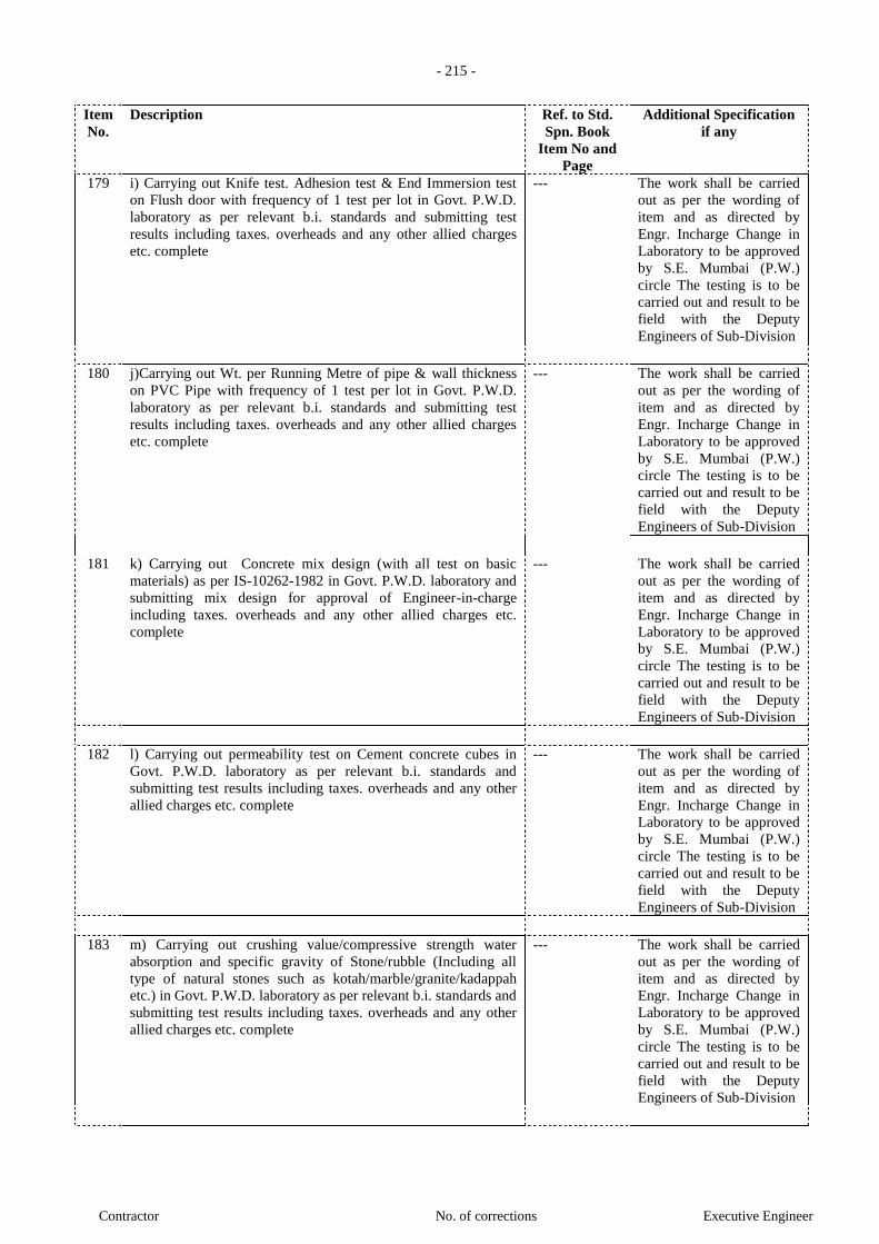
- 215 -
Contractor No. of corrections Executive Engineer
Item
No.
Description Ref. to Std.
Spn. Book
Item No and
Page
Additional Specification
if any
179 i) Carrying out Knife test. Adhesion test & End Immersion test
on Flush door with frequency of 1 test per lot in Govt. P.W.D.
laboratory as per relevant b.i. standards and submitting test
results including taxes. overheads and any other allied charges
etc. complete
--- The work shall be carried
out as per the wording of
item and as directed by
Engr. Incharge Change in
Laboratory to be approved
by S.E. Mumbai (P.W.)
circle The testing is to be
carried out and result to be
field with the Deputy
Engineers of Sub-Division
180 j)Carrying out Wt. per Running Metre of pipe & wall thickness
on PVC Pipe with frequency of 1 test per lot in Govt. P.W.D.
laboratory as per relevant b.i. standards and submitting test
results including taxes. overheads and any other allied charges
etc. complete
--- The work shall be carried
out as per the wording of
item and as directed by
Engr. Incharge Change in
Laboratory to be approved
by S.E. Mumbai (P.W.)
circle The testing is to be
carried out and result to be
field with the Deputy
Engineers of Sub-Division
181 k) Carrying out Concrete mix design (with all test on basic
materials) as per IS-10262-1982 in Govt. P.W.D. laboratory and
submitting mix design for approval of Engineer-in-charge
including taxes. overheads and any other allied charges etc.
complete
--- The work shall be carried
out as per the wording of
item and as directed by
Engr. Incharge Change in
Laboratory to be approved
by S.E. Mumbai (P.W.)
circle The testing is to be
carried out and result to be
field with the Deputy
Engineers of Sub-Division
182 l) Carrying out permeability test on Cement concrete cubes in
Govt. P.W.D. laboratory as per relevant b.i. standards and
submitting test results including taxes. overheads and any other
allied charges etc. complete
--- The work shall be carried
out as per the wording of
item and as directed by
Engr. Incharge Change in
Laboratory to be approved
by S.E. Mumbai (P.W.)
circle The testing is to be
carried out and result to be
field with the Deputy
Engineers of Sub-Division
183 m) Carrying out crushing value/compressive strength water
absorption and specific gravity of Stone/rubble (Including all
type of natural stones such as kotah/marble/granite/kadappah
etc.) in Govt. P.W.D. laboratory as per relevant b.i. standards and
submitting test results including taxes. overheads and any other
allied charges etc. complete
--- The work shall be carried
out as per the wording of
item and as directed by
Engr. Incharge Change in
Laboratory to be approved
by S.E. Mumbai (P.W.)
circle The testing is to be
carried out and result to be
field with the Deputy
Engineers of Sub-Division

- 216 -
Contractor No. of corrections Executive Engineer
Item
No.
Description Ref. to Std.
Spn. Book
Item No and
Page
Additional Specification
if any
184 n) Carrying out weight per running meter diameter of pipe
weight of zinc coating per square meter and wall thickness of
pipe on Galvanized iron pipe in Govt. P.W.D. laboratory as per
relevant b.i. standards and submitting test results including taxes.
overheads and any other allied charges etc. complete
--- The work shall be carried
out as per the wording of
item and as directed by
Engr. Incharge Change in
Laboratory to be approved
by S.E. Mumbai (P.W.)
circle The testing is to be
carried out and result to be
field with the Deputy
Engineers of Sub-Division
185 o) Carrying out thickness mass per running meter and powder
coating test on Aluminum section in Govt. P.W.D. laboratory as
per relevant b.i. standards and submitting test results including
taxes. overheads and any other allied charges etc. complete
--- The work shall be carried
out as per the wording of
item and as directed by
Engr. Incharge Change in
Laboratory to be approved
by S.E. Mumbai (P.W.)
circle The testing is to be
carried out and result to be
field with the Deputy
Engineers of Sub-Division
186 p) Carrying out Tensile strength percentage Elongation. yield
Stres. Weight-per Meter. Bend / Rebend. proof stress and nitrol
solution Test on Steel bar upto 16mm (set of 3 bars) in Govt.
P.W.D. laboratory as per relevant b.i. standards and submitting
test results including taxes. overheads and any other allied
charges etc. complete
--- The work shall be carried
out as per the wording of
item and as directed by
Engr. Incharge Change in
Laboratory to be approved
by S.E. Mumbai (P.W.)
circle The testing is to be
carried out and result to be
field with the Deputy
Engineers of Sub-Division
187 q) Carrying out Tensile strength percentage Elongation. yield
Stres. Weight-per Meter. Bend / Rebend. proof stress and nitrol
solution Test on Steel bar above 16mm (set of 3 bars) in Govt.
P.W.D. laboratory as per relevant b.i. standards and submitting
test results including taxes. overheads and any other allied
charges etc. complete
--- The work shall be carried
out as per the wording of
item and as directed by
Engr. Incharge Change in
Laboratory to be approved
by S.E. Mumbai (P.W.)
circle The testing is to be
carried out and result to be
field with the Deputy
Engineers of Sub-Division
188 r) Carrying out resistance to applied Voltage (1Hr. Test) (set of 2
Bars), resistance to applied voltage (30 days test) (set of 2 bars),
thickness of coating (set of 2 bars). Chemical Resistance test (set
of 8 bars) Hardness of Coating and Salt Spray test (4 cycles) (set
of 2 bars) on steel bars in Govt. P.W.D. laboratory as per
relevant b.i. standards and submitting test results including taxes.
overheads and any other allied charges etc. complete
--- The work shall be carried
out as per the wording of
item and as directed by
Engr. Incharge Change in
Laboratory to be approved
by S.E. Mumbai (P.W.)
circle The testing is to be
carried out and result to be
field with the Deputy
Engineers of Sub-Division
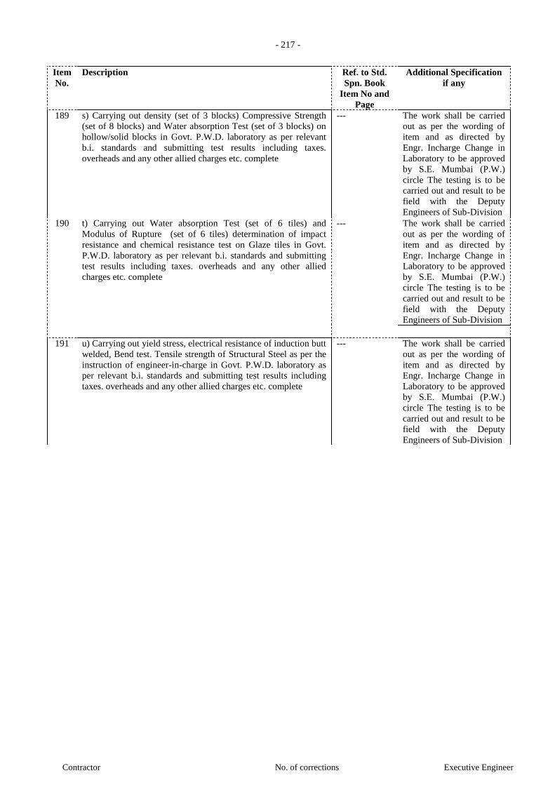
- 217 -
Contractor No. of corrections Executive Engineer
Item
No.
Description Ref. to Std.
Spn. Book
Item No and
Page
Additional Specification
if any
189 s) Carrying out density (set of 3 blocks) Compressive Strength
(set of 8 blocks) and Water absorption Test (set of 3 blocks) on
hollow/solid blocks in Govt. P.W.D. laboratory as per relevant
b.i. standards and submitting test results including taxes.
overheads and any other allied charges etc. complete
--- The work shall be carried
out as per the wording of
item and as directed by
Engr. Incharge Change in
Laboratory to be approved
by S.E. Mumbai (P.W.)
circle The testing is to be
carried out and result to be
field with the Deputy
Engineers of Sub-Division
190 t) Carrying out Water absorption Test (set of 6 tiles) and
Modulus of Rupture (set of 6 tiles) determination of impact
resistance and chemical resistance test on Glaze tiles in Govt.
P.W.D. laboratory as per relevant b.i. standards and submitting
test results including taxes. overheads and any other allied
charges etc. complete
--- The work shall be carried
out as per the wording of
item and as directed by
Engr. Incharge Change in
Laboratory to be approved
by S.E. Mumbai (P.W.)
circle The testing is to be
carried out and result to be
field with the Deputy
Engineers of Sub-Division
191 u) Carrying out yield stress, electrical resistance of induction butt
welded, Bend test. Tensile strength of Structural Steel as per the
instruction of engineer-in-charge in Govt. P.W.D. laboratory as
per relevant b.i. standards and submitting test results including
taxes. overheads and any other allied charges etc. complete
--- The work shall be carried
out as per the wording of
item and as directed by
Engr. Incharge Change in
Laboratory to be approved
by S.E. Mumbai (P.W.)
circle The testing is to be
carried out and result to be
field with the Deputy
Engineers of Sub-Division
- 218 -
Contractor No. of corrections Executive Engineer
SECTION – 8
SECURITIES AND OTHER FORMS

- 219 -
Contractor No. of corrections Executive Engineer
Letter of Acceptance
(Letterhead paper of the Employer)
To,
________________________ [name and address of the Contractor]
Dear Sirs,
This is to notify you that your online bid dated ____________ for execution of the
______________________________________ (name of he contract and identification number, as given in
the Instructions to Bidders) for the Contract Price of Rupees ___________________________
(______________) (amount in words and figures), as corrected and modified in accordance with the
Instructions to Bidders1 is hereby accepted by our agency.
We accept / do not accept that _____________________ be appointed as the Adjudicator2.
You are hereby requested to furnish Performance Security, in the form detailed in Para 34.1 of ITB for an
amount equivalent to Rs. _____________ within 07 days of the receipt of the letter of acceptance valid up to
28 days from the date of expiry of defects Liability Period i.e. up to _______________and sign the contract,
failing which action as stated in Para 34.2 of ITB will be taken.
Yours faithfully,
Authorised Signature
Name and title of Signatory
Name of Agency
1 Delete “Corrected and” or “and modified” if only one of these actions applies. Delete as corrected and
modified in accordance with the Instructions to Bidders, if corrections or modifications have not been
affected.
2 To be used only if the contractor disagrees in his Bid with the Adjudicator proposed by the Employer in the “
Instructions to Bidders”.

- 220 -
Contractor No. of corrections Executive Engineer
Issue of Notice to proceed with the work
(Letter head paper of the Employer)
__________________(Date)
To,
________________________ [name and address of the Contractor]
Dear Sirs,
Pursuant to your furnishing the requisite security as stipulated in ITB Clause 34.1 and signing of the
Contract for the
Bid Price of Rs.____________ .
You are hereby instructed to proceed with the execution of the said works in accordance with
the documents.
Yours faithfully,
(Signature, name and title of Signatory
Authorised to sign on behalf of Employer)
- 221 -
Contractor No. of corrections Executive Engineer
AGREEMENT FORM
Agreement
This agreement, made the ___________ day of _____________between __________(name and
address of the Employer) [hereinafter called “the Employer] and ______________________ (name and
address of contractor) hereinafter called “the Contractor” of the other part.
Whereas the employer is desirous that the Contractor execute _______________________(name and
identification number of Contractor) (hereinafter called “the Works”) and the Employer has accepted the Bid
by the Contractor for the execution and completion of such Works and the remedying of any defects therein,
at a
cost of Rs____________
NOW THIS AGREEMENT WITNESSTH as follows :
(1) In this Agreement, words and expression shall have the same meanings as are respectively assigned to
them in the conditions of contract hereinafter referred to and they shall be deemed to form and be read
and construed as part of this Agreement.
(2) In consideration of the payments to be made by the Employer to the Contractor as hereinafter
mentioned, the Contractor hereby covenants with the Employer to all aspects with the provisions of
the contract.
(3) The Employer hereby covenants to pay the Contractor in consideration of the execution and
completion of the Works and the remedying the defects wherein Contract Price or such other sum as
may become payable under the provisions of the Contract at the times and in the manner prescribed
by the Contract.
(4) The following documents shall be deemed to form and be ready construed as part of this agreement
viz.
i) Letter of Acceptance
ii) Notice to proceed with the works
iii) Contractor’s Bid
iv) Condition of contract : General and Special
v) Contract Date
vi) Additional condition
vii) Drawings
viii) Bill of Quantities and
ix) Any other documents listed in the Contract Data as forming part of the Contract.
In witnessed whereof the parties there to have caused this Agreement to be executed the day and year
first before written.
The Common Seal of __________ was hereunto affixed in the presence of :
Signed, Sealed and Delivered by the said ___________________________
in the presence of :
Binding Signature of Employer _______________________________________________
Binding Signature of Contractor ______________________________________________
- 222 -
Contractor No. of corrections Executive Engineer
UNDERTAKING
[Bid Validity Form]
I, the undersigned do hereby undertake that our firm M/s. _________________
________________________________ agree to abide by this bid for a period _______ days for the date fixed
for receiving the same and it shall be binding on us and may be accepted at any time before the expiration of
that period.
(Signed by an Authorized Officer of the Firm)
Title of Officer
Name of Firm
DATE
- 223 -
Contractor No. of corrections Executive Engineer
SECTION – 9
DRAWINGS

- 224 -
Contractor No. of corrections Executive Engineer
DOCUMENTS TO BE FURNISHED BY THE BIDDER
(Attached)
- 225 -
Contractor No. of corrections Executive Engineer
SECTION – 10
BAR CHART

- 226 -
Contractor No. of corrections Executive Engineer
DOCUMENTS TO BE FURNISHED BY THE BIDDER
(Attached)

- 227 -
Contractor No. of corrections Executive Engineer
* END OF THE TENDER DOCUMNET *