part d81 design railway tracks contents...effective date: july 2018 specification: part d81 design...
TRANSCRIPT

Effective Date: July 2018 Specification: Part D81 Design – Railway Tracks
DPTI Page 1
PART D81
DESIGN – RAILWAY TRACKS
CONTENTS
1. GENERAL 2. REFERENCES 3. CONFIGURATION 1 (INTERIM) TRACK ALIGNMENT – BROAD GAUGE (1600mm) 4. DESIGN STAGES
1. GENERAL
.1 This Part specifies the requirements for the design of the DPTI railway track geometry.
2. REFERENCES
.1 Unless otherwise specified, all design for the DPTI railway track; as a minimum; must be undertaken in accordance with the following:
DPTI Engineering Standards:
PTS-MS-10-SG-STD-00000094 (Pit and Conduit Standard for Signalling and Communication Cables);
PTS-MS-10-SG-STD-00000033 (Signal Sighting Standard);
PTS-MS-10-TR-STD-00000047 (Structural Clearances);
PTS-AR-10-SG-STD-00000068 (Signalling Principles and Practices);
TC4-DOC-000357 (Non-Rail Service Installations within the Rail Corridor);
TC1-DOC-000386 (Engineering Decision - Change to: Track and Civil Infrastructure COP Vol 2 - Train System - To Support Higher Track Speeds);
AR-EL-STD-0102 (Guidelines for the Protective Provisions Related to Electrical Earthing and Bonding For the Adelaide Metro Electrified Rail Network);
DPTI Rail Engineering Management Documents:
PR-AM-GE-807 (Development and Approval of Engineering Waivers);
PTS-MS-05-AM-PRS-00000091 (Asset Management Technical Data Requirements for Projects);
AM4-DOC-000364 (Drafting Standard for AutoCAD Drawings);
PTS-AR-10-EG-PRC-00203000 (Obtaining Type Approval for Safety Critical Rail Assets Procedure);
DPTI Code of Practice (COP) Documents:
Volume 1 – Risk Management:
CP-TS-922 (Risk Assessment – Train);
CP-TS-923 (Risk Assessment – Tram);
Volume 2 – Train System:
CP-TS-952 (Structure and Application);
CP-TS-954 (Operational Signage);
CP-TS-956 (Track Geometry);
CP-TS-957 (Structures);
CP-TS-958 (Drainage);
CP-TS-959 (Formation and Drainage);
CP-TS-960 (Track Support Systems);
CP-TS-961 (Rail and Rail Joints);
CP-TS-962 (Guard/Check Rails, Buffer Stops and Derails);
CP-TS-963 (Points and Crossings);
CP-TS-964 (Rail Stress Control);
CP-TS-965 (Access Control and Protection);
Effective Date: July 2018 Specification: Part D81 Design – Railway Tracks
DPTI Page 2
CP-TS-966 (Fire Prevention and Control);
Volume 3 – Tram System:
CP-TS-972 (Structure and Application);
CP-TS-974 (Operational Signage);
CP-TS-975 (Structural Clearances);
CP-TS-976 (Track Geometry);
CP-TS-977 (Structures);
CP-TS-978 (Stormwater Drainage);
CP-TS-979 (Earthworks);
CP-TS-980 (Track Support Systems);
CP-TS-981 (Rails and Rail Joints);
CP-TS-982 (Guard/Check Rails, Buffer Stops and Derails);
CP-TS-983 (Points and Crossings);
CP-TS-984 (Rail Stress Control);
CP-TS-985 (Access Control and Protection);
CP-TS-986 (Fire Prevention and Control);
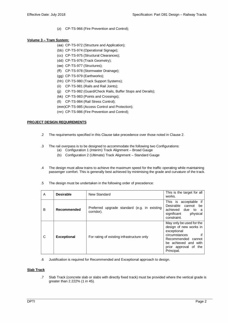
PROJECT DESIGN REQUIREMENTS
.2 The requirements specified in this Clause take precedence over those noted in Clause 2.
.3 The rail overpass is to be designed to accommodate the following two Configurations: Configuration 1 (Interim) Track Alignment – Broad Gauge
Configuration 2 (Ultimate) Track Alignment – Standard Gauge
.4 The design must allow trains to achieve the maximum speed for the traffic operating while maintaining passenger comfort. This is generally best achieved by minimising the grade and curvature of the track.
.5 The design must be undertaken in the following order of precedence:
A Desirable New Standard This is the target for all works.
B Recommended Preferred upgrade standard (e.g. in existing corridor).
This is acceptable if Desirable cannot be achieved due to a significant physical constraint.
C Exceptional For rating of existing infrastructure only
May only be used for the design of new works in exceptional circumstances if Recommended cannot be achieved and with prior approval of the Principal.
.6 Justification is required for Recommended and Exceptional approach to design.
Slab Track
.7 Slab Track (concrete slab or slabs with directly fixed track) must be provided where the vertical grade is greater than 2.222% (1 in 45).

Effective Date: July 2018 Specification: Part D81 Design – Railway Tracks
DPTI Page 3
.8 The Principal’s preference is for slab track to be provided throughout the project area with no change to track structure along the rising/falling gradients.
.9 The Contractor are to define slab track construction methodology.
.10 Embedded rail systems are not to be used.
Ballasted Track
.11 As a minimum, ballasted track is to be provided in locations where the vertical grade is equal to or less than 2.222% (1 in 45).
Slab Track to Ballasted Track Transition
.12 The Contractor must design a track support transition between the slab track and the ballasted track to: provide a progressive change in track stiffness;
provide an easily maintained trackform transition, which will not be prone to differential settlement;
provide accurate matching of track alignment under all load conditions, in order to avoid stress concentrations in components or uneven ride characteristics;
achieve the nominated levels of vibration and regenerated noise attenuation; and
minimise the number of transition sections.
Noise
.13 The Contractor must mitigate against rail noise (Refer Part D20 Design Road Infrastructure).
Vibration
.14 The Contractor must mitigate against rail vibration (Refer Part D20 Design Road Infrastructure).
Track Geometry
.15 The Configuration 1 (Broad Gauge – Train System) track geometry design must allow for Configuration 2 (Standard Gauge – Tram System) DPTI track geometry requirements.
Design Speed
Parameter Unit Desirable Recommended Exceptional
Track Design Speed (V)
km/hr 90 - -
.16 Operational speeds will be advised by DPTI.
Horizontal Alignment
.17 An overpass must only have tangent track alignment; unless required at the tie-in to existing track alignments.
.18 The number of horizontal curves is to be minimised.
Horizontal Geometry
.19 Horizontal geometry parameters:
Parameter Unit Desirable Recommended Exceptional
Min. Track Centres - Tangent Track (Slab Track)
m 4.000 3.900 -
Min. Track Centres - Tangent Track (Ballasted Track)
m 4.000 - -
Bogie Centres (bc) m 17.500 - -

Effective Date: July 2018 Specification: Part D81 Design – Railway Tracks
DPTI Page 4
.20 Note the following: Other relevant DPTI COP standards, noted in Clause 2 “References” are to be adhered to.
Minimum track centres must be 3.900m along the Slab Track section of the new rail alignment subject to an Engineering Waiver, which is to be prepared by the Contractor for review/approval by DPTI. This may be reduced at the adjacent level crossings.
Minimum track centres must be 4.000m along the Ballasted Track section of the new rail alignment.
Track centres must be increased for curvature.
Transitions to be Clothoid.
The Min. Track Centres on Tangent Track (Ballasted Track) is the minimum desirable spacing to be achieved. Where not achievable e.g. adjacent to existing track with centres less than 4m, if the minimum desirable spacing must be achieved at a point nearest feasible to existing sub-4m centre track, such that coincident vertical and horizontal curves are avoided this will be acceptable in principle, however requires supplementary detailed assessments during design development by DPTI.
Vertical Geometry
.21 Vertical geometry parameters:
Parameter Unit Desirable Recommended Exceptional
Max. Grade - Ballasted Track
% (1:x) 1.0% (1:100) 2.222% (1:45) -
Max. Grade - Slab Track
% (1:x) 3.0% (1:33) - -
.22 Note the following: Other relevant DPTI COP standards, noted in Clause 2 “References”, to be adhered to.
Vertical curves are required between grades if the difference in grades is greater than 0.2%.
Vertical curves are to be rounded up to the next multiple of 20m.
The maximum gradients noted above are actual gradients.
Vertical grades to be compensated for horizontal curvature.
Vertical curves must not be located on horizontal transitions or curves, unless agreed by the Contractor.
Vertical curves are not to adversely affect signal sighting requirements.
Rail Operational Signage
.23 Existing DPTI operational signs must be salvaged, stored and reinstalled in their existing location by the Contractor unless agreed with the Principal (i.e. existing temporary speed restrictions due to track condition to be removed).
.24 New DPTI signs must be designed in accordance with standard DPTI drawings. Rail operational signage must include:
Track Design Speed (V)
Minimum K Value
110 75
100 60
90 50
80 40
70 30
60 20
50 15
40 10
35 10

Effective Date: July 2018 Specification: Part D81 Design – Railway Tracks
DPTI Page 5
track markers, required at fouling points; and
speed signs
.25 Rail operational signage must not affect required sighting distances.
Track Monuments and Kilometre Posts
.26 Track monuments and kilometre posts are to be installed as per DPTI COP requirements.
Structural Clearances
.27 Structural Clearances must be in accordance with DPTI standards: PTS-MS-10-TR-STD-00000047 (Structural Clearances –Train System);
200-A3-82-1658 (Maximum Outline for Metropolitan Railway Rolling Stock & Equipment, 1600mm Gauge);
301-A2-86-2239 (S.T.A. Allowable Infringements, Minimum Structures – 1600mm Gauge);
301-A2-86-2240 (Minimum Structures – 1600mm Gauge).
.28 The above design guidelines are to be reviewed against the requirements of the following design guidelines, and the more conservative standard or specification must be adopted. Any conflicting requirements identified must be referred to DPTI for resolution:
CP-TS-975 (Structural Clearances – Tram System); and
301-A2-81-118 (Tram System – Minimum Structures – Tram Line).
.29 Note: the following drawings noted in CP-TS-975 (Structural Clearances – Tram System) are not to be used:
200-A2-2003-104 ( Tram System – Maximum Static Rolling Stock Outline; and
301-A2-2003-102 (Tram System – Minimum Structure Outline);
.30 Any proposed reduction in the structural clearances require Engineering Waivers, which are to be prepared by the Contractor for review/approval by DPTI.
.31 The Configuration 1 (Broad Gauge – Train System) structural clearance design must allow for Configuration 2 (Standard Gauge – Tram System) and associated electrical clearances (vertical and horizontal).
Structures
.32 Design of track structures must be in accordance with DPTI Standards: CP-TS-957 (Structures – Train System)
.33 The above design guideline is to be reviewed against the requirements of the following design guideline, and the more conservative standard or specification must be adopted. Any conflicting requirements identified must be referred to DPTI for resolution:
CP-TS-977 (Structures – Tram System)
Stormwater and Drainage
.34 Design of track drainage must be in accordance with DPTI Standard: CP-TS-958 (Drainage – Train System)
.35 The above design guideline is to be reviewed against the requirements of the following design guideline, and the more conservative standard or specification must be adopted. Any conflicting requirements identified must be referred to DPTI for resolution:
CP-TS-978 (Storm Water Drainage – Tram System)
Formation and Earthworks
.36 Design of the Formation and Earthworks must be in accordance with DPTI Standard: CP-TS-959 (Formation and Earthworks – Train System)

Effective Date: July 2018 Specification: Part D81 Design – Railway Tracks
DPTI Page 6
.37 The above design guideline is to be reviewed against the requirements of the following design guideline, and the more conservative standard or specification must be adopted. Any conflicting requirements identified must be referred to DPTI for resolution:
CP-TS-979 (Earthworks – Tram System)
Track Support System
Design Loading
.38 The Design Axle Loading is:
Parameter Maximum Axle Load Maximum Operating Speed
Passenger Diesel & Trams 21 tonne 90 km/hr
Rail
.39 As a minimum, new AS 50kg non head hardened rail is to be used throughout the Slab Track and a minimum of 10m prior to the track support transition (i.e. on ballasted track on the approach to the track support transition).
Rail Fastening System
.40 The Contractor is to propose any Rail Fastening System to be approved by DPTI.
.41 The Rail Fastening System is to attenuate noise and vibration.
.42 The Contractor must describe within the Design Basis Report how the transition for the Configuration 1 to Configuration 2 rail fastening requirements will be met.
Sleepers
.43 Sleepers for the ballasted track structure must be ‘Gauge Convertible Precast Concrete Sleepers’. These sleepers will be free issued by the Principal.
.44 Sleeper spacing must be in accordance with CP-TS-960 (Track Support Systems – Trains).
.45 Sleepers must be installed such that the gauge convertible end of the sleeper is orientated on the six-foot side allowing for increased clearance to the adjacent track when gauge conversion occurs.
Attachment to Sleepers
.46 The ‘Gauge Convertible Precast Concrete Sleepers’ have provision for the coring of holes for the installation of a ferrule allowing for the attachment of (if required) check rails, guard rails, Automatic Warning System (AWS), etc.
.47 If required, the Contractor must design and install the ferrule appropriate for the requirements of the item to be installed. The Contractor must modify the associated concrete sleepers to provide for ferrules.
Additional Requirements for Inaccessible Sleepers
.48 In locations where sleepers are covered or where fasteners are inaccessible for future inspection, the Contractor must provide galvanised fastenings.
Ballast
.49 Ballast must be new Class N60 nominal size.
Rail Joints
.50 The Contractor must design for Continuously Welded Track.
.51 Welds must be ‘Flash Butt’ unless approved by the Principal.
.52 Aluminothermic welds may be used: Where temporary track alignment is required; and

Effective Date: July 2018 Specification: Part D81 Design – Railway Tracks
DPTI Page 7
at the tie-in to existing rails; a minimum of 10m prior to the track support transitions.
.53 Mechanical rail joints must not be used.
Guard Rails
Guard rails are defined as: Rails (inside or outside the running rails) used to restrain lateral movement of a derailed wheelset and used to protect structures or control the lateral movement of the wheelset on bridges or in other higher risk situations.
Guard rails must not induce thermal stress into the track structure. Joints at appropriate locations and zero toe load fastenings may be utilised to assist in achieving this requirement.
Contractor; based on COP requirements and risk/construction workshops; are to define Guard Rail requirements, and if contrary to COP requirements then Engineering Waivers are to be prepared by the Contractor for review/approval by DPTI.
Check Rails
.54 Check rails are defined as a rail placed inside the running rail which comes into contact with the back of the wheel flange and must be used:
to prevent a vehicle from derailing or to re-rail a derailed vehicle where it would be in danger of striking a structure with consequential personal injury or property damage; or
to prevent a vehicle from derailing or to re-rail a derailed vehicle where it was in danger of toppling over the side of an overbridge.
.55 Rerailers are to be provided should Check Rails be required.
.56 Contractor; based on COP requirements and risk/construction workshops; are to define Check Rail requirements, and if contrary to COP requirements then Engineering Waivers are to be prepared by the Contractor for review/approval by DPTI.
Rail Stress Control
.57 The Contractor must provide a rail stress management plan which will detail the methodology and order of stressing of the rail to achieve the target stress free temperature as specified in:
CP-TS-964 (Rail Stress Control – Train System)
.58 The above design guideline is to be reviewed against the requirements of the following design guideline, and the more conservative standard or specification must be adopted. Any conflicting requirements identified must be referred to DPTI for resolution:
CP-TS-9984 (Rail Stress Control –Tram System)
Access Control and Protection
.59 Design of the Access Control and Protection must be in accordance with DPTI Standard:
CP-TS-965 (Access Control and Protection – Train System)
.60 The above design guideline is to be reviewed against the requirements of the following design guideline, and the more conservative standard or specification must be adopted. Any conflicting requirements identified must be referred to DPTI for resolution:
CP-TS-985 (Access Control and Protection – Tram System)
Clearance Register
.61 Following completion of the works; including verification; the Contractor must complete and submit a clearance register for the project area.
Signalling
.62 Design of signalling must be in accordance with Part D82 Design Signalling.
Pedestrian Crossings
.63 If part of the works, pedestrian crossing design must be undertaken in accordance with the standards prescribed in Clause 2 and project specific information provided by the Principal.

Effective Date: July 2018 Specification: Part D81 Design – Railway Tracks
DPTI Page 8
Level Crossings
.64 If part of the works, level crossing design must be undertaken in accordance with the standards prescribed in Clause 2 and project specific information provided by the Principal.
As Constructed Drawings
.65 Following completion of the works; including verification; the Contractor must complete and submit ‘As Constructed’ drawings for the project area.
.66 As a minimum, drawings and documentation is to adhere to the following DPTI standard: PTS-MS-05-AM-PRS-00000091 (Asset Management Technical Data Requirements for Projects)
Emergency Egress
.67 The Contractor must undertake a risk assessment, to determine the requirement(s) for emergency provisions within the overpass to enable passengers and/or train crews to detrain to the overpass and for safe egress from the overpass.
.68 Submission and acceptance of the risk assessment to determine and specify the requirements for emergency egress shall constitute a HOLD POINT.
.69 If required; following the risk assessment; an emergency walkway shall be provided within the overpass and must meet the following performance criteria:
provide a safe, uniform, smooth, slip resistant walking surface and meet the reasonable requirements of Emergency Services personnel;
allow for safe and efficient egress from a train in the event of an emergency;
provision of the walkways must take account of rolling stock types and associated detrainment facilities;
the width of the walkways must be agreed with the Principal, but as a minimum shall be 850mm wide. The walkway envelope must extend 2100mm above the walkway level;
walkways in the vicinity of pedestrian crossings are to be designed to prevent unauthorised access; and
the walkway level must be agreed with the principal stakeholders.
.70 If elevated walkways are to be provided, the following criteria; in addition to those above; shall also apply: elevated walkways must have a handrail on the overpass wall side of the walkway that must not
obstruct the safe and efficient egress from a train in the event of an emergency;
elevated walkways must have DDR compliant access ramps from track level.;
elevated walkways must be installed 100mm clear of horizontal platform dimensions; and
elevated walkways must not obstruct signal sighting or signal equipment.
.71 The design of the emergency egress walkways is to take into account Configuration 2 electrification requirements.
Emergency Egress Lighting
.72 The Contractor must undertake a risk assessment, to determine the requirement(s) for emergency lighting provisions within the overpass to enable passengers and/or train crews to detrain to the overpass and for safe egress.
.73 Submission and acceptance of the risk assessment to determine and specify the requirements for emergency egress lighting shall constitute a HOLD POINT.
Overpass Lighting
.74 The rail overpass does not require lighting, other than the requirements determined for emergency egress requirements.
Safety Refuges
.75 The Contractor must undertake a risk assessment, to determine the requirement(s) for Safety Refuges within the overpass.
.76 Submission and acceptance of the risk assessment to determine and specify the requirements for Safety Refuges shall constitute a HOLD POINT.

Effective Date: July 2018 Specification: Part D81 Design – Railway Tracks
DPTI Page 9
Earthing and Bonding
.77 The track must be constructed to accommodate earthing and bonding requirements for Configuration 2.
Stray Current
.78 The track must be constructed to accommodate stray current requirements for Configuration 2.
Overhead
.79 The track must be constructed to accommodate overhead electrical 600 V DC supply requirements for Configuration 2.
Extent of Rail Works
.80 The track geometry must be designed to tie in to the existing track geometry through level crossings. The Contractor must advise on any economic benefits that can be achieved by designing through the level crossings.
Type Approvals
.81 Proposed items must be type approved by DPTI.
Geometric Design Documentation
.82 Rail drawings must be in accordance with DPTI Standard: DP 001 – General Requirements (Design Presentation – Construction Drawings) and any other relevant DPTI rail standard.
.83 As a minimum, the following design details must be included in the design documentation: survey co-ordinates and datums;
location details (bench marks, tangent spiral, spiral curve, vertical curves, changes in grades);
curvature;
length of curves;
gradient;
cant;
cant deficiency;
maximum allowable speed;
transition length;
cant gradient;
horizontal alignment tie in details; and
Vertical alignment tie in details.
Risk Assessment
.84 The Contractor must undertake risk assessment of the design for the Railway Related Works in accordance with the requirements of AS 4292.
3. CONFIGURATION 1 (INTERIM) TRACK ALIGNMENT – BROAD GAUGE (1600mm)
.1 The track design, clearances and associated infrastructure must incorporate the requirements for Configuration 2.
.2 Configuration 1 must consider adjustment of both broad gauge rail lines to maintain minimum track centres.
.3 The Contractor must detail and document in the design of the Slab Track the future works the procedures or methodologies to modify and remediate the Slab Track to enable for Configuration 2.
.4 The requirements specified in this Clause take precedence over those noted in Clause 2.
Temporary Track Alignment
.5 Design Speed requirements are as below:
Parameter Unit Desirable Recommended Exceptional
Track Design Speed (V)
km/hr 35 - -
Effective Date: July 2018 Specification: Part D81 Design – Railway Tracks
DPTI Page 10
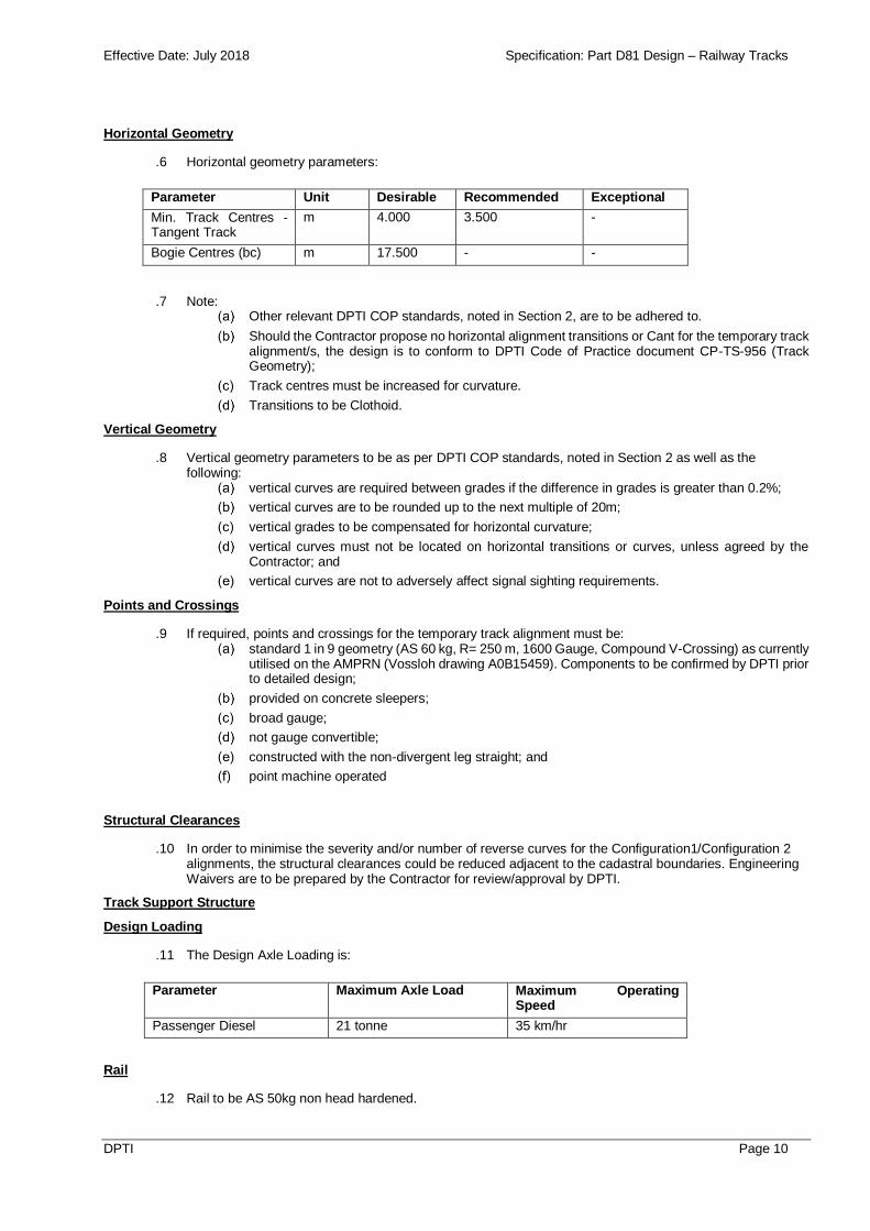
Horizontal Geometry
.6 Horizontal geometry parameters:
Parameter Unit Desirable Recommended Exceptional
Min. Track Centres - Tangent Track
m 4.000 3.500 -
Bogie Centres (bc) m 17.500 - -
.7 Note: Other relevant DPTI COP standards, noted in Section 2, are to be adhered to.
Should the Contractor propose no horizontal alignment transitions or Cant for the temporary track alignment/s, the design is to conform to DPTI Code of Practice document CP-TS-956 (Track Geometry);
Track centres must be increased for curvature.
Transitions to be Clothoid.
Vertical Geometry
.8 Vertical geometry parameters to be as per DPTI COP standards, noted in Section 2 as well as the following:
vertical curves are required between grades if the difference in grades is greater than 0.2%;
vertical curves are to be rounded up to the next multiple of 20m;
vertical grades to be compensated for horizontal curvature;
vertical curves must not be located on horizontal transitions or curves, unless agreed by the Contractor; and
vertical curves are not to adversely affect signal sighting requirements.
Points and Crossings
.9 If required, points and crossings for the temporary track alignment must be: standard 1 in 9 geometry (AS 60 kg, R= 250 m, 1600 Gauge, Compound V-Crossing) as currently
utilised on the AMPRN (Vossloh drawing A0B15459). Components to be confirmed by DPTI prior to detailed design;
provided on concrete sleepers;
broad gauge;
not gauge convertible;
constructed with the non-divergent leg straight; and
point machine operated
Structural Clearances
.10 In order to minimise the severity and/or number of reverse curves for the Configuration1/Configuration 2 alignments, the structural clearances could be reduced adjacent to the cadastral boundaries. Engineering Waivers are to be prepared by the Contractor for review/approval by DPTI.
Track Support Structure
Design Loading
.11 The Design Axle Loading is:
Parameter Maximum Axle Load Maximum Operating Speed
Passenger Diesel 21 tonne 35 km/hr
Rail
.12 Rail to be AS 50kg non head hardened.

Effective Date: July 2018 Specification: Part D81 Design – Railway Tracks
DPTI Page 11
Rail Fastening System
.13 Contractor to propose and to be approved by DPTI.
Sleepers
.14 Concrete sleepers; approved by DPTI; to be used.
Ballast
.15 Ballast must be Class N60 nominal size.
Rail Joints
.16 As per COP requirements. The Contractor must design for Continuously Welded Track.
Guard Rails
.17 As per COP requirements.
Check Rails
.18 As per COP requirements.
Rail Stress Control
.19 The Contractor must provide a rail stress management plan which will detail the methodology and order of stressing of the rail to achieve the target stress free temperature as specified in:
CP-TS-964 (Rail Stress Control – Train System)
Access Control and Protection
.20 As per COP requirements.
Clearance Register
.21 Following completion of the works; including verification; the Contractor must complete and submit a clearance register for the project area.
Signalling
.22 Design of signalling must be in accordance with standards noted in Part D082.
Pedestrian crossings
.23 Pedestrian crossing design is not included in the project.
Level Crossings
.24 Level crossing design is not included in the project.
Geometric Design Documentation
.25 As per Clauses 3.82-3.83
CONFIGURATION 2 (ULTIMATE) TRACK ALIGNMENT – STANDARD GAUGE (1435mm)
.26 The Configuration 2 track alignment is to cater for rolling stock authorised along the Adelaide Convention Centre to Glenelg Tram line.
.27 Any Configuration 2 required track, civil, electrical, signalling, communications, etc. equipment is not to be designed and/or constructed (unless agreed to by the Contractor) at Configuration 1; however the Configuration 1 design is to accommodate requirements for Configuration 2.
.28 The Ultimate Track Alignment must have a minimum of 4.000m track centres.
.29 Parts of the SKM document “Tramline Overhead Wiring and Substation Upgrade – Draft Traction System Bonding Philosophy – 28 May 2009” have been incorporated into AR-EL-STD-0102. Tram requirements noted in the SKM document, but not covered in AR-EL-STD-0102 must also be complied with.

Effective Date: July 2018 Specification: Part D81 Design – Railway Tracks
DPTI Page 12
4. DESIGN STAGES
Concept Design (notionally 15% design)
.1 At a minimum, the Design Report provided at the Notionally 15% Complete Stage must include: Concept Track General Arrangement Plans
Research and determine appropriate k value for vertical curves
Design Basis Report
Preliminary Design (notionally 30% design)
.2 At a minimum, the Design Report provided at the Notionally 30% Complete Stage must include: Preliminary Track General Arrangement Plans
Preliminary Vertical Alignment Drawings
Preliminary Turnout Crossing Geometry
Preliminary Geometry Tables
Preliminary Track Speed and Gauge Schematic
Preliminary Drainage Scheme
Preliminary Clearance Diagrams
Design Development Report (inc. A summary of any Engineering Waivers required for development of the Detailed Design stage)
Asset List skeleton
Detailed Design (notionally 70% complete)
.3 At a minimum, the Design Report provided at the Notionally 70% Complete Stage must include: Detailed Track General Arrangement Plans
Detailed Vertical Alignment Drawings
Detailed Turnout Crossing Geometry
Detailed Geometry Tables
Detailed Track Speed and Gauge Schematic
Detailed Clearance Diagrams
Detailed drainage design
Detailed Design Report (inc. Completed Engineering Waivers of issues identified in the Preliminary Design stage, A summary of any additional Engineering Waivers sought due to development of the Detailed Design)
Preliminary Asset List in accordance with PTS91.
Final Design (notionally 100% complete)
.4 At a minimum, the Design Report provided at the Notionally 100% Complete Stage must include: Final Track General Arrangement Plans
Final Vertical Alignment Drawings
Final Turnout Crossing Geometry
Final Geometry Tables
Final Track Speed and Gauge Schematic
Final Clearance Diagrams
Final drainage design
Final Design Report (inc. All Engineering Waivers completed).
Final Asset List in accordance with PTS91.
____________