part cc05 steel reinforcement contents - dpti · part cc05 steel reinforcement contents 1. general...
TRANSCRIPT

Edition: June 2012 Specification: Part CC05 Steel Reinforcement
DPTI
PART CC05
STEEL REINFORCEMENT
CONTENTS
1. GENERAL 2. QUALITY REQUIREMENTS 3. SUPPLY AND PLACEMENT OF REINFORCING 4. MEASUREMENT 5. HOLD POINTS 6. VERIFICATION REQUIREMENTS AND RECORDS
1. GENERAL
.1 This Part specifies the requirements for the supply and placement of reinforcing steel used for the reinforcement of concrete structures. Refer to Part S24 “Pre-tensioned Concrete” and Part S25 “Post –tensioned Concrete” for requirements for steel prestressing materials.
.2 Documents referenced in this Part are listed below:
AS 1554.3: Structural Steel Welding - Welding of Reinforcing Steel
AS4671: Steel Reinforcing Materials
AS 3600: Concrete Structures
AS 5100: Bridge Design
2. QUALITY REQUIREMENTS
.1 The Contractor must prepare and implement a Quality Plan that includes detailed procedures for:
(a) verifying that the reinforcing has been fabricated and placed within the specified tolerances and providing documentary evidence of conformance.
.2 If not provided beforehand, the procedures must be submitted at least 28 days prior to the commencement of site work. Provision of the procedures listed in this Clause shall constitute a HOLD POINT.
3. SUPPLY AND PLACEMENT OF REINFORCING
General
.1 The reinforcing must comply with AS 4671 and must be fabricated and installed in accordance with AS5100.1 (highway related structures) or AS 3600 (all other structures) as appropriate. The Contractor must provide certification that the reinforcing complies with AS 4671.
.2 Manufacturers and processors of steel reinforcement must hold a valid certificate of approval issued by the Australasian Certification Authority for Reinforcing and Structural Steels (ACRS). Refer to http://www.acrs.net.au. Provision of this certification shall constitute a HOLD POINT.
.3 If Bar Bending Schedules are not supplied by the Principal, the Contractor must supply copies of the Bending Schedules at least 2 working days prior to delivery of bars to the site. Provision of the Contractor’s Bending Schedules shall constitute a HOLD POINT.
Fabrication and Bending
.4 Reinforcement which requires fabrication or bending to shape must be supplied in the full length shown on the drawings. Reinforcement must be cold bent to the specified shape. Bars must not be bent after fabrication unless shown on the drawings.
Laps
.5 Straight bars must be supplied to the full lengths shown on the drawings. Where lapping of straight bars is unavoidable, such laps must be staggered and a minimum of two wire ties placed at each lap.
Welding of Bars
.6 Welding of reinforcement must not be used unless prior approval has been obtained. If approved, the welding must be in accordance with AS1554.3. Any permitted tack welding must be performed such

Edition: June 2012 Specification: Part CC05 Steel Reinforcement
DPTI
that no loss of section of bars occurs. High strength bolts or rods cast into concrete must not be welded.
.7 Submission of a proposal for any welding of reinforcement shall constitute a HOLD POINT. Where
appropriate, the proposal must be supported by evidence that the welding will not be detrimental to the performance of the structure.
Placing and Fastening
.8 Steel spacers (including plastic coated or tipped) must not be used to maintain cover. Parallel layers of reinforcement must be held in their correct relative positions by steel spacers only. If mortar block spacers are used to maintain cover, the blocks must have properties at least equal to that of the surrounding concrete as specified and their colour and cement type must be the same as that of the surrounding concrete.
.9 Provision of evidence that mortar block spacers comply with this Clause shall constitute a HOLD POINT.
Cover and Tolerances
.10 The cover (or "clear cover") as stated on the drawings, must be the clear distance from the face of any reinforcement, wire ties for fixing reinforcement, formwork fixings or similar metal work to the nearest concrete surface. Tolerances on the position of reinforcement controlled by cover in bridge deck slabs must be 5 mm. The Contractor’s Quality system must provide documented evidence that the reinforcement has been placed within the specified cover and tolerances.
4. MEASUREMENT
.1 If the reinforcement mass has been provided by the Principal in the Schedule of Rates or Bill of Quantities, it has been calculated from the net lengths shown on the drawings excluding laps, hooks, bends, cogs and wastage and from the nominal bar diameters.
5. HOLD POINTS
.1 The following is a summary of Hold Points referenced in this Part:
CLAUSE REF.
HOLD POINT RESPONSE
TIME
2.2 Submission of Procedures 7 days
3.2 Certification of compliance with AS4671 and ACRS 1 day
3.3 Provision of the Contractor’s Bending Schedules 1 day
3.7 Proposal to weld reinforcing bars 3 days
3.9 Evidence of compliance of mortar block spacers 1 day
6. VERIFICATION REQUIREMENTS AND RECORDS
.1 The Contractor must supply the following records:
CLAUSE REF.
SUBJECT RECORD TO BE PROVIDED
3.1 Compliance with AS 4671 and ACRS
Certificate of conformance to AS 4671 and ACRS
3.10 Cover and tolerances Evidence of conformance
____________

Edition: April 2011 Specification: Part CC10 Formwork
DPTI
PART CC10
FORMWORK
CONTENTS
1. GENERAL 2. QUALITY REQUIREMENTS 3. CONSTRUCTION REQUIREMENTS 4. HOLD POINTS
1. GENERAL
.1 This Part specifies the requirements for the design, erection and stripping of formwork.
.2 Documents referenced in this Part are listed below:
AS 3610 Formwork for Concrete
AS 3972 Portland and Blended Cements
.3 Unless specified otherwise, formwork must comply with AS 3610 and the definitions in AS 3610 shall apply to this Part (Note that the definition of “formwork” is inclusive of “falsework”).
2. QUALITY REQUIREMENTS
General
.1 The Contractor must prepare and implement a Quality Plan that includes detailed procedures and documentation for:
(a) formwork - design and materials; and
(b) formwork documentation (refer AS 3610, Section 4).
.2 If not provided beforehand, the procedures and documentation must be submitted at least 14 days prior to the commencement of site work. The Contractor must ensure that the formwork documentation (refer AS 3610, Section 4) is completed and available on site at all times during formwork construction, use and dismantling.
.3 Provision of the procedures and documentation listed in this Clause shall constitute a HOLD POINT.
Formwork Design
.4 This sub-clause applies to any formwork where there would be serious consequences (such as a risk to the safety of any person, a delay to work on the critical path or a compromise to the quality of the Works) in the event of the failure of the formwork to perform as intended.
.5 The formwork design must be certified by a design engineer that the design complies with the requirements of this Contract. The design engineer must be a Chartered Professional Engineer with qualifications admitting to Corporate Membership of the Institution of Engineers and be experienced in the design of structures / formwork.
.6 Provision of the formwork design shall constitute a HOLD POINT.
3. CONSTRUCTION REQUIREMENTS
General
.1 The Contractor must ensure that the formwork will achieve the requirements of Clause CC25.7 Surface Finish” and Clause CC25.8 “Tolerances”.

Edition: April 2011 Specification: Part CC10 Formwork
DPTI
Stripping Times
.2 Minimum formwork stripping times for vertical faces must be in accordance with AS 3610, Table 5.4.1. Table 5.4.1 may also be used for stripping times in the case of beam or slab soffits provided that there is compliance with the following conditions:
(a) The ratio of span between supports (permanent and/or retained temporary) to the overall depth of the member is less than:
100
280
D
where D is the overall depth of the section in millimetres;
(b) the concrete conforms with Part CC20 "Supply of Concrete"; and
(c) the concrete has a cementitious component limited to cement type GP or SR complying with AS 3972, without mineral additions to the concrete mix.
.3 Where cement types GB, HE or LH are a component of the concrete or where a percentage of type GP cement has been replaced by flyash in accordance with Clause CC20.1.3.1 "Cement", the stripping times given above must be doubled.
.4 For steam cured and hot water cured precast units, stripping times may be reduced in accordance with Part CC35 "Low Pressure Steam Curing of Precast Units" or Part CC36 "Heat Accelerated Curing” as appropriate. In these cases, forms may be removed at the completion of steam curing or hot water curing.
Superimposed Loads
.5 Superimposed loads must not be placed on concrete slabs cast on top of precast planks or spanning between steel or precast concrete girders until 0.75 x the characteristic compressive strength of the cast-in-place concrete at 28 days is achieved. Superimposed loads must be limited to 2.0 kN/m2 or a point load of 2.0 kN until the characteristic compressive strength of the cast-in-place concrete at 28 days is achieved and until the concrete is at least 14 days old. Unless shown otherwise on the drawings, bridge decks must be poured in one continuous operation without construction joints.
Composite Construction
.6 All deck formwork for composite construction must be completely supported from the superstructure girders except at bearing locations where it may be supported from the sill.
4. HOLD POINTS
.1 The following is a summary of Hold Points referenced in this Part:
CLAUSE REF
HOLD POINT RESPONSE TIME
2.3 Submission of procedures and formwork documentation 5 working days
2.6 Certification of formwork design by Chartered Professional Engineer 5 working days
____________

Edition: January 2014 Specification: Part CC20 Supply of Concrete
DPTI
PART CC20
SUPPLY OF CONCRETE
CONTENTS
1. GENERAL 2. QUALITY REQUIREMENTS 3. CONCRETE MATERIALS 4. CONCRETE PROPERTIES 5. SAMPLING AND TESTING 6. HIGH DURABILITY CONCRETE 7. TEST PROCEDURES 8. HOLD POINTS 9. VERIFICATION REQUIREMENTS AND RECORDS
1. GENERAL
.1 This Part specifies the requirements for the design, supply, sampling and testing of special class concrete and normal class in excess of 32MPa. Refer to Part CC26 “Normal Class Concrete” for the supply of N20, N25 and N32 normal class concrete.
.2 Concrete and its constituent materials must be supplied and tested in accordance with the following:
AS 1012 Methods of testing concrete
AS 1141 Methods of sampling and testing aggregates
AS 1379 Specification and supply of concrete
AS 1478 Chemical admixtures for concrete
AS 2758.1 Aggregates and rock for engineering purposes - Concrete aggregates
AS 3582 Supplementary cementations materials for use with portland and blended cement
AS 3972 Portland and blended cements
.3 Unless specified otherwise, the definitions in AS 1379 apply to this Part.
2. QUALITY REQUIREMENTS
.1 At a minimum, the Contractor’s Quality Plan must include the following documents, procedures and instructions:
(a) the concrete mix design, including:
i) the source, type and proportions of the constituent materials;
ii) aggregate gradings and saturated surface-dry densities;
iii) chemical admixtures details and manufacturer's recommended method of use;
iv) the nominated slump and where a superplasticizer is used the final slump;
v) if self compacting concrete is proposed, details of the mix, T500 (measure of viscosity) and passing ability;
vi) the maximum water content and maximum water/cementitious material ratio;
vii) level of control, accuracy and method of determination of both the coarse and fine aggregate moisture content; and
viii) documentary evidence that the mix will comply with the specified requirements this Contract from either previous production of the mix (the test results must not be more than 12 months old) or full details of a trial mix undertaken in accordance with AS 1012.2.
(b) detailed procedures for concrete production, delivery, material testing and concrete testing.
.2 If not provided beforehand, the documentation must be submitted at least 28 days prior to the commencement of site work.
.3 Provision of the procedures and documentation listed in this Clause shall constitute a HOLD POINT.

Edition: January 2014 Specification: Part CC20 Supply of Concrete
DPTI
.4 The Contractor is responsible for ensuring that the concrete mix design will achieve all of the requirements for plastic and hardened concrete that are specified in this Contract. In the event of any change to the mix design, the above documentation must be resubmitted prior to manufacture of the changed mix.
3. CONCRETE MATERIALS
Cement
.1 Cement must comply with AS 3972. Cement for each batch of concrete must be from one manufacturer and of one brand and type. Cement more than 3 months old must not be used in the Works unless it is re-tested to demonstrate compliance with the requirements of AS 3972.
Admixtures
.2 Admixtures must:
(a) comply with AS 1478.1;
(b) be dispensed using equipment complying with Clause 3.4 “Liquid Dispensing Equipment” of AS 1379;
(c) not contain calcium chloride; and
(d) not contain any chemical in a concentration which could have a detrimental effect on the concrete durability or any other concrete property.
Aggregate
.3 Fine and coarse aggregate for concrete must comply with the requirements of AS 2758.1 unless otherwise specified. The maximum sizes of coarse aggregates used must not exceed the values shown in Table 3.3.
TABLE 3.3 MAXIMUM AGGREGATE SIZE
Type of Concrete Location Maximum Size of Coarse Aggregate
Permissible
All cases Clear cover 0.75 x clear cover
Prestressed Concrete All cases 20 mm
Reinforced Concrete All sections whose least dimension is up to 300 mm
20 mm
All sections whose least dimension is greater than 300 mm
40 mm
Piles and closely reinforced sections 20 mm or 0.66 x the minimum clear distance between parallel reinforcing bars whichever is the lesser
Unreinforced Concrete All cases 55 mm
.4 Particle shape must comply with Clause 9 “Verification Requirements and Records”.
.5 The aggregate, when used in the proposed mix design, must not be susceptible to alkali aggregate reactivity and the Contractor must provide evidence to verify this. Refer Vicroads Technical Note 30: Alkali Silica Reaction in Concrete, available from: http://www.bookshop.vicroads.vic.gov.au/redirectpdf/pdfs/tn030.pdf.
Soluble Salts
.6 The acid-soluble chloride-ion content of concrete as placed (expressed as the percentage of the total mass of cementitious material in the concrete mix) must not be greater than:
(a) 0.1% for prestressed concrete
(b) 0.15% for reinforced concrete
(c) 0.03% for post-tensioning grout.
.7 The sulphate content of concrete as placed (expressed as the percentage by mass of acid-soluble SO3 to the total cementitious material in the concrete mix) must not be greater than 5%. Sulphate and chloride-ion content must be determined by testing of hardened concrete in accordance with AS 1012.20.

Edition: January 2014 Specification: Part CC20 Supply of Concrete
DPTI
Self Compacting Concrete
.8 Self Compacting Concrete (SCC) (also called self-consolidating concrete or super-workable concrete) is concrete that is able to flow and consolidate under its own weight, completely fill the formwork or bore hole even in the presence of dense reinforcement, whilst maintaining homogeneity and without the need for additional compaction. For further information, refer to Vicroads Technical Note 73: Self Compacting Concrete, available from: http://www.bookshop.vicroads.vic.gov.au/redirectpdf/pdfs/tn073.pdf,
.9 SCC must incorporate the various cementitious materials, coarse and fine aggregate and any additional fine materials, water and chemical admixtures in such proportions as required, to achieve the rheological characteristics of flow and self-compaction and an absence of segregation. SCC must be produced using high range polycarboxylate type water reducers or conventional superplasticizers with a viscosity modifying admixture which include a viscosity modifying capability.
4. CONCRETE PROPERTIES
Concrete Class
.1 Unless specified otherwise, all concrete supplied in accordance with this Contract is Special-Class Concrete. The minimum cementitious content and the maximum water-cement ratio for each particular grade of concrete must be accordance with Table 4.1.
TABLE 4.1 CEMENT AND WATER CONTENT
CLASS OF CONCRETE
MINIMUM CEMENTITIOUS CONTENT (Kg) PER CUBIC METRE
OF CONCRETE
MAXIMUM WATER-CEMENT RATIO BY MASS (SSD BASIS)
32 320 .58
40 380 .50
50 460 .40
.2 The exposure classification must be as shown on the drawings or in THE CONTRACT SPECIFIC REQUIREMENTS.
Self Compacting Concrete
.3 SCC must be homogeneous and free of balls of unmixed material. SCC must only be used for the manufacture of precast concrete members and / or the construction of cast in-situ piles. The properties of fresh SCC must comply with either:
(a) the requirements specified in Clause 9. “Verification Requirements and Records”; or
(b) Annexure B80/G – Self-Compacting Concrete of NSW Roads and Maritime Services QA Specification B80 “Concrete Work for Bridges”, available from http://www.rta.nsw.gov.au/doingbusinesswithus/specifications/index.html.
5. SAMPLING AND TESTING
.1 All concrete must be subject to assessment to Project Assessment unless specified otherwise on the drawings or in THE CONTRACT SPECIFIC REQUIREMENTS.
.2 For Project Assessment, the following sampling and testing must be undertaken in addition to that specified in AS1379:
(a) A slump test (or Slump Flow if self compacting concrete is used) on each truck load of concrete delivered to site; and
.3 sampling in accordance with Table 5.1
TABLE 5.1 SAMPLING FREQUENCY (per day)
No. of batches (trucks) supplied to the Project
No. of samples to be taken
1 1
2 to 5 2

Edition: January 2014 Specification: Part CC20 Supply of Concrete
DPTI
Greater than 5 For each additional 5 batches: One additional sample
.4 Samples must be selected randomly.
.5 Three cylinder specimens must be obtained from each sample, to be tested as follows:
(a) one tested at 7 days (to give an indication of the likely 28 strength only); and
(b) the remaining 2 cylinder specimens tested at 28 days (conformance testing).
.6 If the Contractor proposes to conduct in-house testing for determination of concrete strength for lifting or transfer, evidence must be provided showing that:
(a) the testing equipment is adequately calibrated and maintained;
(b) the testing processes are appropriate; and
(c) the testing personnel are adequately trained.
6. HIGH DURABILITY CONCRETE
.1 This clause only applies where high durability concrete has been specified on the drawings or in THE CONTRACT SPECIFIC REQUIREMENTS. High durability concrete must have a chloride permeability
of less than 1 500 coulombs as measured by TP541 Rapid Determination of the Chloride Permeability of Concrete (refers AASHTO T277 and ASTM C1202).
.2 The test acceptance of a concrete mix design must be carried out on test specimens taken from a concrete sample of age 28 days, which has undergone standard moist curing. The sample must consist of 2 cylinders and one test specimen must be taken from the upper section of each cylinder. The value of chloride permeability must be taken as the average of the results of the two tests. Frequency of sampling and testing must be as follows:
TABLE 6.1 HIGH DURABILITY SAMPLING FREQUENCY
COMPONENT NO. OF SAMPLES TO BE TAKEN
Initial mix design 1 per mix design
Piles 1 from first concrete pour 1 in each subsequent 30 piles
Pile caps 1 from first concrete pour 1 from fourth pile cap pour
Skirts and fender beams 1 from first concrete pour for each element
Piers 1 from first concrete pour 1 from fourth pier pour
Abutments 1 from each abutment pour
.3 The Contractor may propose an alternative testing regime using acceptance criteria of a standard not less than RTA QA Specification B80 “Concrete Work for Bridges”, Clause 3.2.1 “Durability Provisions A (performance)” or Vicroads Standard Specification 610 “Structural Concrete” Clause 610.06. Any such testing regime is subject to prior approval in accordance with Special Conditions of Contract Clause 21 “Alternatives Proposed by the Contractor”.
7. TEST PROCEDURES
.1 The Contractor must use the following test procedures (refer http://www.dpti.sa.gov.au/contractor_documents) to verify conformance with the Specification:
TEST TEST PROCEDURE
Rapid determination of the chloride permeability of concrete TP541 (refers AASHTO T277 and
ASTM C1202)
Slump test AS 1012.3
Compressive strength of concrete specimens AS 1012.9

Edition: January 2014 Specification: Part CC20 Supply of Concrete
DPTI
Self Compacting Concrete - Slump flow, T500 time (measure of viscosity) and passing ability
Vicroads Test Method 252.01 *
Standard Test Method for Passing Ability of Self-consolidating Concrete J-Ring
ASTM C1621/C1621M-09b
* Included in the Vicroads Code of Practice RC500.16, available from: http://www.vicroads.vic.gov.au.
8. HOLD POINTS
.1 The following is a summary of Hold Points referenced in this Part:
CLAUSE REF.
HOLD POINT RESPONSE TIME
2.3 Submission of mix designs and procedures 2 working days
9. VERIFICATION REQUIREMENTS AND RECORDS
Test Records
.1 The Contractor must undertake the testing specified in this Clause and supply written evidence of compliance with the lot package.
CLAUSE REF.
SUBJECT PROPERTY PROCEDURE FREQUENCY ACCEPTANCE LIMITS
3.3-3.5 Aggregate Properties
(Project Assessment
only)
Particle Shape As specified in AS 2758.1, Clause 8.3
At least once for each aggregate type
As specified in AS 2758.1, Clause 8.3
Water absorption As specified in AS 2758.1, Clause 7.3
At least once for each aggregate type
< 2.5%
3.8-3.9 Self Compacting Concrete (if not using RMS B80 Specification)
slump flow Vicroads RC 252.01
Refer Clause 5. 550-750mm spread. Aggregate must be evenly distributed throughout the concrete paste & must not exhibit signs of segregation.
T500 time (measure of viscosity)
Vicroads RC 252.01
Refer Clause 5. A spread of 500 mm within 2 – 5 seconds. The final spread must not exceed 750 mm diameter
Passing Ability Vicroads RC 252.01
Refer Clause 5. The concrete must not exhibit signs of segregation.
4 & 5 Concrete Properties
Cement and Water Content
Determined from identification certificate (refer AS1379 Clause 1.7.3)
Each truck load Table 4.1
Slump Refer AS1379 Each truck load Refer AS1379 Clause 5.2
Compressive Strength– Production Assessment
Refer AS1379 Refer AS1379 Refer AS1379
7 day Compressive Strength– Project Assessment
Refer AS1379 Refer Table 5.1 and Clause 5
Report Only

Edition: January 2014 Specification: Part CC20 Supply of Concrete
DPTI
CLAUSE REF.
SUBJECT PROPERTY PROCEDURE FREQUENCY ACCEPTANCE LIMITS
28 day Compressive Strength– Project Assessment
Refer AS1379 Refer Table 5.1 and Clause 5
Refer AS1379
6 High Durability Concrete
Permeability Limit
TP541 Refer Table 6.1 < 1500 coulombs
Other Records
.2 The Contractor must supply the following records:
CLAUSE REF.
SUBJECT RECORD TO BE PROVIDED
5 In-house testing of concrete properties
Evidence of satisfactory equipment and processes and trained personnel
5 Concrete Delivery Information
Identification certificates in accordance with AS 1379: Clause 1.7. 3 “Identification Certificate”
5 7 day compressive strength
If the result is < 65% of the specified 28 day compressive strength, a report outlining the Contractor’s proposed disposition is to be provided within 2 days of completion of the test.
____________

Edition: April 2011 Specification: Part CC25 Placement of Concrete
DPTI
PART CC25
PLACEMENT OF CONCRETE
CONTENTS
1. GENERAL 2. QUALITY REQUIREMENTS 3. CONCRETE PLACEMENT 4. FINISHING OF UNFORMED CONCRETE SURFACES 5. CURING 6. CRACKING OF CONCRETE 7. SURFACE FINISH 8. TOLERANCES 9. HOLD POINTS
FIGURE 1 EVAPORATION RATE FROM FRESHLY PLACED CONCRETE
1. GENERAL
.1 This Part specifies the requirements for the placement, curing and stripping of concrete and the properties of the finished product.
.2 Documents referenced in this Part are listed below:
AS 1379 The Specification and Manufacture of Concrete
AS 1478.1 Admixtures for Concrete
AS 2758.1 Concrete Aggregates
AS 3610 Formwork for Concrete
AS 3600 Concrete Structures
AS 3799 Liquid Membrane - Forming Curing Compounds for Concrete
AS 3972 Portland and Blended Cements
HB64 Guide to Concrete Construction (joint publication of the Cement and Concrete Association of Australia and Standards Australia
Vicroads Standard Specification 687 “Repair of Concrete Cracks” and 689 “Cementitious Patch Repair of Concrete, available from http://webapps.vicroads.vic.gov.au/VRNE/csdspeci.nsf/
2. QUALITY REQUIREMENTS
.1 At a minimum, the Contractor’s Quality Plan must include the following documents, procedures and instructions:
(a) procedures describing the proposed method of placing, compacting, finishing and curing the concrete, including the rate of placement, the number of personnel required and their responsibilities and required competencies, and the plant and equipment to be used, including required standby equipment;
(b) procedures for set out and level control for bridge deck pours (where applicable);
(c) procedures describing the measures that will be taken to protect freshly placed concrete and prevent evaporative moisture loss during finishing operations of concrete slabs;
(d) details of the materials and measures to ensure compliance with the specified curing requirements;
(e) the type of curing compound; and
(f) procedures for precast abutment panel construction and installation (where applicable).
.2 If not provided beforehand, the documentation must be submitted at least 28 days prior to the commencement of site work.
.3 Provision of the procedures and documentation listed in this Clause shall constitute a HOLD POINT.

Edition: April 2011 Specification: Part CC25 Placement of Concrete
DPTI
3. CONCRETE PLACEMENT
General
.1 Prior to placing concrete, a HOLD POINT shall apply. At least 24 hours notice must be provided prior to
placing concrete. If not previously provided, the Contractor must submit evidence verifying that the reinforcement has been placed within the specified cover and tolerances (refer Clause CC05.3.6 “Cover and Tolerance”).
.2 Except where amended or added to by this Contract, concrete must be transported, handled, placed, compacted, finished and cured in accordance with AS 3600, using the recommended processes described in HB64. Hand mixing is not permitted.
Stand-By Mixing Plant
.3 The Contractor must ensure that alternative supplies of concrete from stand-by mixing plant(s) can be made available immediately in the event of breakdown.
Traceability of Concrete
.4 All concrete batches (truckloads) used in the works must be traceable from the batch plant to its general location in the structure by a unique identification number.
Temperature at Time of Delivery
.5 Concrete when delivered at the acceptance point must have a temperature not less than 5°C nor greater than 35°C (refer AS 1379, Clause 4.4.2).
Construction Joints
.6 All mandatory joints are shown on the drawings. Any proposal for additional planned joints shall constitute a HOLD POINT. All construction joints, including those with keys or dowels, must be roughened to expose
aggregate to provide a bond between the new and old concrete.
Environmental Conditions for Placing Concrete
Requirements for Temperature and Other Adverse Conditions
.7 Concrete must not be placed if the air temperature at the site is below 5°C or the shade temperature at the site is over 35°C. Concreting in the open must not be carried out during adverse conditions, such as rain, wind, dust or bushfires.
Additional Requirements for Elements with high Area to Volume Ratios
.8 Concrete must not be placed in decks, approach slabs and like elements with an area to volume ratio greater than or equal to 5 unless the rate of evaporation determined in accordance with Figure 1 at the end of this Part is less than 1 kg/square metre/hour. In addition, concrete must not be placed when the rate of evaporation is between 0.5 kg/square metre/hour and 1 kg/square metre/hour unless precautionary measures are taken to ensure the concrete can be placed and finished without defects.
Self Compacting Concrete
.9 SCC must not be vibrated. The concrete must not be subjected to any physical disturbance after deposition.
4. FINISHING OF UNFORMED CONCRETE SURFACES
General
.1 Finish on unformed concrete surfaces are classified as follows:
.2 Finish U1 - Screeded Finish
.3 Finish U2 - Wood Floated Finish
.4 Finish U3 - Steel Floated Finish.
Finish U1 - Screeded Finish
.5 A screeded finish will be applied to bridge decks and other surfaces that will be later covered with a bituminous wearing surface or to walkways and other surfaces required to take pedestrian traffic. The surface will be screeded, wood floated and then roughened by broom when the concrete has set sufficiently, to produce regular marks approximately 3 mm deep.

Edition: April 2011 Specification: Part CC25 Placement of Concrete
DPTI
Finish U2 - Wood Floated Finish
.6 A wood floated finish must be applied to all surfaces that are not required to have either a U1 or U3 finish.
Finish U3 - Steel Floated Finish
.7 Unless otherwise specified, a steel floated finish must be applied to prominently exposed surfaces such as tops of wing walls, parapets, end walls, kerbs and the like. The steel floated finish must provide a smooth uniform surface, true to line and level and free of marks.
5. CURING
.1 All curing compounds must comply with AS 3799. Concrete must be cured for 7 days when the concrete contains cement Types GP or SR complying with AS 3972 without mineral additions to the concrete mix, except that decks, footways, approach slabs and like elements with an area to volume ratio greater than or equal to 5 must be cured for 14 days. Unless otherwise specified all elements must have an exposure classification of B1 (refer AS 3600, Clause 4.5).
.2 Where cement Types GB or LH are a component of the concrete the curing times given above must be doubled. Curing compounds must not be applied to the upper surface of bridge decks unless approved otherwise.
.3 For steam cured and hot water cured precast units, curing times may be reduced in accordance with Part CC35 "Low Pressure Steam Curing of Precast Units" or Part CC36 "Heat Accelerated Curing” as appropriate. In these cases, curing may be considered complete at the end of the curing cycle.
6. CRACKING OF CONCRETE
.1 At all times after placement of the concrete, the width of any crack measured at the concrete surface must not exceed:
(a) pre-cast pre-stressed concrete: 0.10 mm;
(b) all other concrete: the relevant value specified in Table 6. 1
TABLE 6.1
Exposure Classification
Maximum Acceptable Crack Widths (mm)
A 0.20
B1 0.20
B2 0.15
C, U 0.10
.2 In the event that crack(s) exceed the values specified above, the Contractor must:
(a) undertake an assessment of the cracked concrete structure (prepared by a technical specialist with a minimum of 5 years practical experience in the diagnostic assessment and investigation of concrete structures) to evaluate the influence of cracks on the load bearing capacity, serviceability and durability;
(b) establish the cause(s) of the cracks, crack width, the moisture condition of the crack and whether a crack is active or inactive;
(c) prepare crack repair procedure / plan; and
(d) repair the cracks to a standard not less than that specified in Vicroads Standard Specification 687 “Repair of Concrete Cracks” or 689 “Cementitious Patch Repair of Concrete” (as appropriate).
.3 Submission of the crack repair procedure / plan shall constitute a HOLD POINT.
7. SURFACE FINISH
Class
.1 The class of finish (as defined in AS3610) on formed concrete surfaces must comply with the following:
(a) Totally concealed areas such as footings and foundation beams – Class 4.
Edition: April 2011 Specification: Part CC25 Placement of Concrete
DPTI
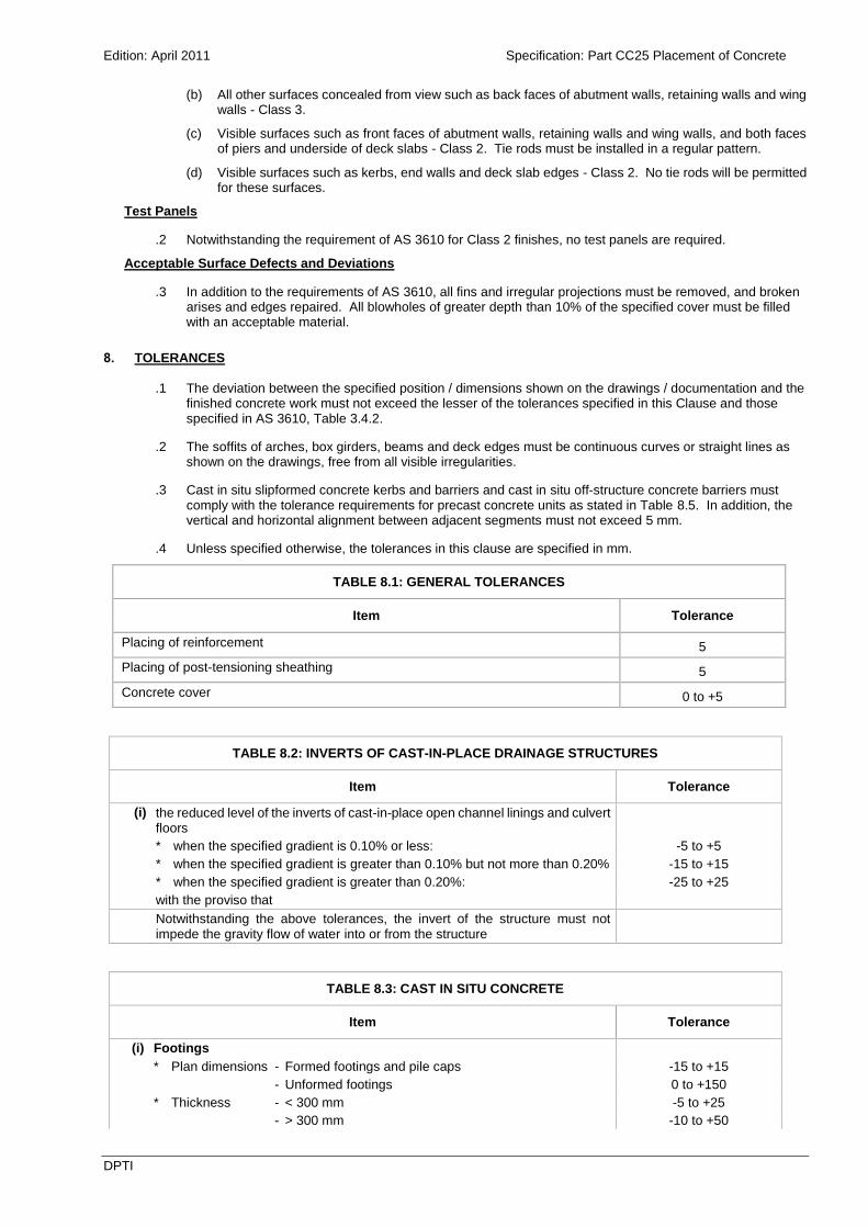
(b) All other surfaces concealed from view such as back faces of abutment walls, retaining walls and wing walls - Class 3.
(c) Visible surfaces such as front faces of abutment walls, retaining walls and wing walls, and both faces of piers and underside of deck slabs - Class 2. Tie rods must be installed in a regular pattern.
(d) Visible surfaces such as kerbs, end walls and deck slab edges - Class 2. No tie rods will be permitted for these surfaces.
Test Panels
.2 Notwithstanding the requirement of AS 3610 for Class 2 finishes, no test panels are required.
Acceptable Surface Defects and Deviations
.3 In addition to the requirements of AS 3610, all fins and irregular projections must be removed, and broken arises and edges repaired. All blowholes of greater depth than 10% of the specified cover must be filled with an acceptable material.
8. TOLERANCES
.1 The deviation between the specified position / dimensions shown on the drawings / documentation and the finished concrete work must not exceed the lesser of the tolerances specified in this Clause and those specified in AS 3610, Table 3.4.2.
.2 The soffits of arches, box girders, beams and deck edges must be continuous curves or straight lines as shown on the drawings, free from all visible irregularities.
.3 Cast in situ slipformed concrete kerbs and barriers and cast in situ off-structure concrete barriers must comply with the tolerance requirements for precast concrete units as stated in Table 8.5. In addition, the vertical and horizontal alignment between adjacent segments must not exceed 5 mm.
.4 Unless specified otherwise, the tolerances in this clause are specified in mm.
TABLE 8.1: GENERAL TOLERANCES
Item Tolerance
Placing of reinforcement 5
Placing of post-tensioning sheathing 5
Concrete cover 0 to +5
TABLE 8.2: INVERTS OF CAST-IN-PLACE DRAINAGE STRUCTURES
Item Tolerance
(i) the reduced level of the inverts of cast-in-place open channel linings and culvert floors
* when the specified gradient is 0.10% or less: -5 to +5
* when the specified gradient is greater than 0.10% but not more than 0.20% -15 to +15
* when the specified gradient is greater than 0.20%: -25 to +25
with the proviso that
Notwithstanding the above tolerances, the invert of the structure must not impede the gravity flow of water into or from the structure
TABLE 8.3: CAST IN SITU CONCRETE
Item Tolerance
(i) Footings
* Plan dimensions - Formed footings and pile caps -15 to +15
- Unformed footings 0 to +150
* Thickness - < 300 mm -5 to +25
- > 300 mm -10 to +50

Edition: April 2011 Specification: Part CC25 Placement of Concrete
DPTI
TABLE 8.3: CAST IN SITU CONCRETE
Item Tolerance
* Top of footing or pile cap reduced level -25 to +25
* Departure from the plan position in any direction 50
(ii) Cylinders
* Variation from the vertical 25 mm in 3 m
* Departure from the plan position in any direction 75
(iii) Variation in Cross Section of Columns, Piers, Pier and Abutment Crossheads, Slabs, Walls, Beams and Similar Parts (excluding deck slabs
and end posts)
* < 3 m -5 to +15
* > 3 m -10 to +25
(iv) Variation of Cross Section of End Posts -5 to +5
(v) Deck
Thickness of Deck Slabs (excluding allowance for correction of camber or hog) 0 to +10
Deck surface reduced level -10 to +10
(vi) Deck Joints
* Width of slot -3 to +3
(vii) Variation from Vertical or Specified Batter of Columns, Piers, Walls, Handrail Posts and Arrises
* Unexposed concrete 10 mm in 2.5 m (1/250)
* Exposed concrete 5 mm in 2.5 m (1/500)
(viii) Variation from Grades Indicated on Drawings for Railings, Kerbs and Arrises
2.5 mm in 2.5 m (1/1000)
(ix) Reduced Level of Tops of Pier and Abutment Crossheads and Piers
* With pedestals -10 to +10
* Without pedestals -5 to +5
* Difference in Level across width of crosshead 5
(x) Bearing Pedestals
* Reduced level -2.0 to +2.0
* Variation from grade across the width of individual pedestals must not exceed
1 in 200
* Deviation from flat surface +1.0 to -1.0
(xi) Departure from Plan Position at any level
* Columns, Piers, Walls, Pier and Abutment Crossheads, Beams, Slabs, Kerbs, Railing and other similar parts
25
* Relative displacement of adjoining components must not exceed 10
(xii) Departure from Alignment
* Rows of columns, faces of piers or walls 10
* Handrails, Faces of hand rail posts, Kerbs 5
(xiii) Maximum Allowance for Irregularities in Exposed Concrete Surfaces
* Sections less than 1 m in dimension when measured with a straightedge across the dimension of the section
2.5
* Sections greater than 1 m in dimension when measured with a straightedge across the dimension of the section, except that when sections are greater than 2.5 m in dimension, a 2.5 m straightedge must be used
5
(xiv) Irregularities in Railings 2.5 mm in 2.5 m
(xv) Slab Surface Finish 5 mm in 2.5 m
TABLE 8.4: PRE-TENSIONED CONCRETE
Item Tolerance
(i) Cross Section
* Dimension - < 2 m -3 to +3
- > 2 m -6 to +6

Edition: April 2011 Specification: Part CC25 Placement of Concrete
DPTI
TABLE 8.4: PRE-TENSIONED CONCRETE
Item Tolerance
* Out of square - > 2 m 0.5 in 250, or Desirable 3, Maximum 5
(ii) Strand and Reinforcement
* Placing of reinforcement 5
* Placing of prestressing strand 3
* Concrete cover 0 to +5
(iii) Squareness of Ends Deviation from a plane perpendicular to the longitudinal axis of a member, or from the specified end plane:
* Dimension - < 500 mm 3
* - > 500 mm 6 mm per metre (10 mm maximum)
(iv) Length
* Diagonal length for precast unit 5
* Overall length or length centre to centre of bearings (for beams and slabs)
0.06% x specified length (max 20)
* Centre to centre spacing of holes for transverse rods or both
5
(v) Profile in a Vertical Plane (Hog) The deviation in hog of any unit from the mean hog of all units must not vary by more than 0.07% of the length of the units. The absolute value for hog for any unit must not be less than zero. Hog measurements must be made at transfer of prestress.
(vi) Profile in a Horizontal Plane (Bow) The deviation of a unit from the required profile must not exceed 0.06% of the length of the unit or a maximum of 15 mm.
(vii) Twist The angular rotation of any cross section relative to an end cross section must not exceed 1 in 200.
(viii) Sole Plates The plane of the sole plate or bearing surface must not vary from that shown on the drawings by more than 1 in 200 in any direction.
(ix) Deviation
* The distance of any point from a flat plane held against that surface.
3 mm in 2 m
TABLE 8.5: PRECAST CONCRETE UNITS
Item Tolerance
(i) General
* Placing of reinforcement 5
* Placing of sheathings for post-tensioned segmental components
5
* Concrete cover 0 to +5
(ii) Cross Section
* Dimension - < 2 m 0 to +3
- > 2 m 0 to +6
* Out of square Maximum 5
(iii) Squareness of Ends Deviation from a plane perpendicular to the longitudinal axis of a member, or from the specified end plane:
* Dimension - < 500 mm 3 mm
* - > 500 mm 6 mm per metre (10 mm maximum)
For parapet units and new jersey barriers, the deviation from a place perpendicular to the longitudinal axis must not exceed 3 mm.
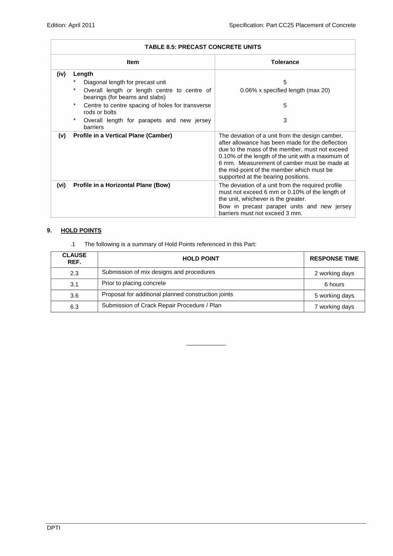
Edition: April 2011 Specification: Part CC25 Placement of Concrete
DPTI
TABLE 8.5: PRECAST CONCRETE UNITS
Item Tolerance
(iv) Length
* Diagonal length for precast unit 5
* Overall length or length centre to centre of bearings (for beams and slabs)
0.06% x specified length (max 20)
* Centre to centre spacing of holes for transverse rods or bolts
5
* Overall length for parapets and new jersey barriers
3
(v) Profile in a Vertical Plane (Camber) The deviation of a unit from the design camber, after allowance has been made for the deflection due to the mass of the member, must not exceed 0.10% of the length of the unit with a maximum of 6 mm. Measurement of camber must be made at the mid-point of the member which must be supported at the bearing positions.
(vi) Profile in a Horizontal Plane (Bow) The deviation of a unit from the required profile must not exceed 6 mm or 0.10% of the length of the unit, whichever is the greater.
Bow in precast parapet units and new jersey barriers must not exceed 3 mm.
9. HOLD POINTS
.1 The following is a summary of Hold Points referenced in this Part:
CLAUSE REF.
HOLD POINT RESPONSE TIME
2.3 Submission of mix designs and procedures 2 working days
3.1 Prior to placing concrete 6 hours
3.6 Proposal for additional planned construction joints 5 working days
6.3 Submission of Crack Repair Procedure / Plan 7 working days
____________

Edition: April 2011 Specification: Part CC25 Placement of Concrete
DPTI
FIGURE 1
EVAPORATION RATE FROM FRESHLY PLACED CONCRETE