part 193—liquefied natural gas facilities: federal … · 193.2629 external corrosion control:...
TRANSCRIPT

91
Research and Special Programs Administration, DOT Pt. 193
B. Other standard reference half cells maybe substituted for the saturated cooper-cop-per sulfate half cell. Two commonly used ref-erence half cells are listed below along withtheir voltage equivalent to ¥0.85 volt as re-ferred to a saturated copper-copper sulfatehalf cell:
(1) Saturated KCl calomel half cell: ¥0.78volt.
(2) Silver-silver chloride half cell used insea water: ¥0.80 volt.
C. In addition to the standard referencehalf cells, an alternate metallic material orstructure may be used in place of the satu-rated copper-copper sulfate half cell if its po-tential stability is assured and if its voltageequivalent referred to a saturated copper-copper sulfate half cell is established.
[Amdt. 192–4, 36 FR 12305, June 30, 1971]
PART 193—LIQUEFIED NATURALGAS FACILITIES: FEDERAL SAFETYSTANDARDS
Subpart A—General
Sec.193.2001 Scope of part.193.2003 Semisolid facilities.193.2005 Applicability.193.2007 Definitions.193.2009 Rules of regulatory construction.193.2011 Reporting.193.2013 Incorporation by reference.193.2015 [Reserved]193.2017 Plans and procedures.193.2019 Mobile and temporary LNG facili-
ties.
Subpart B—Siting Requirements
193.2051 Scope.193.2055 General.193.2057 Thermal radiation protection.193.2059 Flammable vapor-gas dispersion
protection.193.2061 Seismic investigation and design
forces.193.2063 Flooding.193.2065 Soil characteristics.193.2067 Wind forces.193.2069 Other severe weather and natural
conditions.193.2071 Adjacent activities.193.2073 Separation of facilities.
Subpart C—Design
193.2101 Scope.
MATERIALS
193.2103 General.193.2105 Extreme temperatures; normal op-
erations.193.2107 Extreme temperatures: emergency
conditions.
193.2109 Insulation.193.2111 Cold boxes.193.2113 Piping.193.2115 Concrete subject to cryogenic tem-
peratures.193.2117 Combustible materials.193.2119 Records.
DESIGN OF COMPONENTS AND BUILDINGS
193.2121 General.193.2123 Valves.193.2125 Automatic shutoff valves.193.2127 Piping.193.2129 Piping attachments and supports.193.2131 Building design.193.2133 Buildings: ventilation.193.2135 Expansion or contraction.193.2137 Frost heave.193.2139 Ice and snow.193.2141 Electrical systems.193.2143 Lightning.193.2145 Boilers and pressure vessels.193.2147 Combustion engines and turbines.
IMPOUNDMENT DESIGN AND CAPACITY
193.2149 Impoundment required.193.2151 General design characteristics.193.2153 Classes of impounding systems.193.2155 Structural requirements.193.2157 Coatings and coverings.193.2159 Floors.193.2161 Dikes, general.193.2163 Vapor barriers.193.2165 Dike dimensions.193.2167 Covered systems.193.2169 Gas leak detection.193.2171 Sump basins.193.2173 Water removal.193.2175 Shared impoundment.193.2179 Impoundment capacity: general.193.2181 Impoundment capacity: LNG stor-
age tanks.193.2183 Impoundment capacity: equipment
and transfer systems.193.2185 Impoundment capacity: parking
areas, portable containers.
LNG STORAGE TANKS
193.2187 General.193.2189 Loading forces.193.2191 Stratification.193.2193 Movement and stress.193.2195 Penetrations.193.2197 Internal design pressure.193.2199 External design pressure.193.2201 Internal temperature.193.2203 Foundation.193.2205 Frost heave.193.2207 Insulation.193.2209 Instrumentation for LNG storage
tanks.193.2211 Metal storage tanks.193.2213 Concrete storage tanks.193.2215 Thermal barriers.193.2217 Support system.193.2219 Internal piping.
VerDate 29<OCT>99 09:55 Nov 11, 1999 Jkt 183198 PO 00000 Frm 00091 Fmt 8010 Sfmt 8010 Y:\SGML\183198T.XXX pfrm02 PsN: 183198T

92
49 CFR Ch. I (10–1–99 Edition)Pt. 193
193.2221 Marking.
DESIGN OF TRANSFER SYSTEMS
193.2223 General.193.2227 Backflow.193.2229 Cargo transfer systems.193.2231 Cargo transfer area.193.2233 Shutoff valves.
Subpart D—Construction
193.2301 Scope.193.2303 Construction acceptance.193.2304 Corrosion control overview.193.2305 Procedures.193.2307 Inspection.193.2309 Inspection and testing methods.193.2311 Cleanup.193.2313 Pipe welding.193.2315 Piping connections.193.2317 Retesting.193.2319 Strength tests.193.2321 Nondestructive tests.193.2323 Leak tests.193.2325 Testing control systems.193.2327 Storage tank tests.193.2329 Construction records.
Subpart E—Equipment
193.2401 Scope.
VAPORIZATION EQUIPMENT
193.2403 General.193.2405 Vaporizer design.193.2407 Operational control.193.2409 Shutoff valves.193.2411 Relief devices.193.2413 Combustion air intakes.
LIQUEFACTION EQUIPMENT
193.2415 General.193.2417 Control of incoming gas.193.2419 Backflow.193.2421 Cold boxes.193.2423 Air in gas.
CONTROL SYSTEMS
193.2427 General.193.2429 Relief devices.193.2431 Vents.193.2433 Sensing devices.193.2435 Warning devices.193.2437 Pump and compressor control.193.2439 Emergency shutdown control sys-
tems.193.2441 Control center.193.2443 Fail-safe control.193.2445 Sources of power.
Subpart F—Operations
193.2501 Scope.193.2503 Operating procedures.193.2505 Cooldown.193.2507 Monitoring operations.193.2509 Emergency procedures.
193.2511 Personnel safety.193.2513 Transfer procedures.193.2515 Investigations of failures.193.2517 Purging.193.2519 Communication systems.193.2521 Operating records.
Subpart G—Maintenance
193.2601 Scope.193.2603 General.193.2605 Maintenance procedures.193.2607 Foreign material.193.2609 Support systems.193.2611 Fire protection.193.2613 Auxiliary power sources.193.2615 Isolating and purging.193.2617 Repairs.193.2619 Control systems.193.2621 Testing transfer hoses.193.2623 Inspecting LNG storage tanks.193.2625 Corrosion protection.193.2627 Atmospheric corrosion control.193.2629 External corrosion control: buried
or submerged components.193.2631 Internal corrosion control.193.2633 Interference currents.193.2635 Monitoring corrosion control.193.2637 Remedial measures.193.2639 Maintenance records.
Subpart H—Personnel Qualifications andTraining
193.2701 Scope.193.2703 Design and fabrication.193.2705 Construction, installation, inspec-
tion, and testing.193.2707 Operations and maintenance.193.2709 Security.193.2711 Personnel health.193.2713 Training: operations and mainte-
nance.193.2715 Training: security.193.2717 Training: fire protection.193.2719 Training: records.
Subpart I—Fire Protection
193.2801 Scope.193.2803 General.193.2805 Fire prevention plan.193.2807 Smoking.193.2809 Open fires.193.2811 Hotwork.193.2813 Storage of flammable fluids.193.2815 Motorized equipment.193.2817 Fire equipment.193.2819 Gas detection.193.2821 Fire detection.
Subpart J—Security
193.2901 Scope.193.2903 Security procedures.193.2905 Protective enclosures.193.2907 Protective enclosure construction.193.2909 Security communications.
VerDate 29<OCT>99 09:55 Nov 11, 1999 Jkt 183198 PO 00000 Frm 00092 Fmt 8010 Sfmt 8010 Y:\SGML\183198T.XXX pfrm02 PsN: 183198T
93
Research and Special Programs Administration, DOT § 193.2005
193.2911 Security lighting.193.2913 Security monitoring.193.2915 Alternative power sources.193.2917 Warning signs.APPENDIX A TO PART 193—INCORPORATION BY
REFERENCE
AUTHORITY: 49 U.S.C. 5103, 60102, 60103,60104, 60108, 60109, 60110, 60113, 60118; and 49CFR 1.53.
SOURCE: 45 FR 9203, Feb. 11, 1980, unlessotherwise noted.
Subpart A—General§ 193.2001 Scope of part.
(a) This part prescribes safety stand-ards for LNG facilities used in thetransportation of gas by pipeline thatis subject to the pipeline safety laws(49 U.S.C. 60101 et seq.) and Part 192 ofthis chapter.
(b) This part does not apply to:(1) LNG facilities used by ultimate
consumers of LNG or natural gas.(2) LNG facilities used in the course
of natural gas treatment or hydro-carbon extraction which do not storeLNG.
(3) In the case of a marine cargotransfer system and associated facili-ties, any matter other than siting per-taining to the system or facilities be-tween the marine vessel and the lastmanifold (or in the absence of a mani-fold, the last valve) located imme-diately before a storage tank.
(4) Any LNG facility located in navi-gable waters (as defined in Section 3(8)of the Federal Power Act (16 U.S.C.796(8)).
[45 FR 9203, Feb. 11, 1980, as amended byAmdt. 193–1, 45 FR 57418, Aug. 28, 1980; Amdt.193–10, 61 FR 18517, Apr. 26, 1996]
§ 193.2003 Semisolid facilities.An LNG facility used in the transpor-
tation or storage of LNG in a semisolidstate need not comply with any re-quirement of this part which the Direc-tor finds impractical or unnecessarybecause of the semisolid state of LNG.In making such a finding, the Directormay impose appropriate alternativesafety conditions.
§ 193.2005 Applicability.(a) New or amended standards in this
part governing the siting, design, in-stallation, or construction of an LNG
facility and related personnel quali-fications and training do not apply to:
(1) LNG facilities under constructionbefore the date such standards are pub-lished; or
(2) LNG facilities for which an appli-cation for approval of the siting, con-struction, or operation was filed beforeMarch 1, 1978, with the Department ofEnergy (or any predecessor organiza-tion of that Department) or the appro-priate State or local agency in the caseof any facility not subject to the juris-diction of the Department of Energyunder the Natural Gas Act (not includ-ing any facility the construction ofwhich began after November 29, 1979,not pursuant to such an approval).
(b) If an LNG facility listed in para-graph (a) of this section is replaced, re-located, or significantly altered afterFebruary 11, 1980, the replacement, re-located facility, or significantly al-tered facility must comply with the ap-plicable requirements of this part gov-erning siting, design, installation, andconstruction, except that:
(1) The siting requirements applyonly to LNG storage tanks that are sig-nificantly altered by increasing theoriginal storage capacity or relocated,not pursuant to an application for ap-proval filed as provided by paragraph(a)(2) of this section before March 1,1978; and
(2) To the extent compliance with thedesign, installation, and constructionrequirements would make the replaced,relocated, or altered facility incompat-ible with other facilities or would oth-erwise be impracticable, the replaced,relocated, or significantly altered facil-ity may be designed, installed, or con-structed in accordance with the origi-nal specifications for the facility, or ina manner that the Director finds ac-ceptable.
(c) The siting, design, installation,and construction of an LNG facilityunder construction before February 11,1980, or that is listed in paragraph(a)(2) of this section (except a facilityunder construction before July 1, 1976)must meet the applicable requirementsof ANSI/NFPA 59A (1972 edition) andpart 192 of this chapter or the applica-ble requirements of this part, exceptthat no part 192 standard issued after
VerDate 29<OCT>99 09:55 Nov 11, 1999 Jkt 183198 PO 00000 Frm 00093 Fmt 8010 Sfmt 8010 Y:\SGML\183198T.XXX pfrm02 PsN: 183198T
94
49 CFR Ch. I (10–1–99 Edition)§ 193.2007
March 1, 1978, applies to an LNG facil-ity listed in paragraph (a)(2) of thissection.
[45 FR 9203, Feb. 11, 1980, as amended byAmdt. 193–1, 45 FR 57418, Aug. 28, 1980; Amdt.193–2, 45 FR 70404, Oct. 23, 1980; 58 FR 14522,Mar. 18, 1993]
§ 193.2007 Definitions.As used in this part:Administrator means the Adminis-
trator of the Research and Special Pro-grams Administration or any person towhom authority in the matter con-cerned has been delegated by the Sec-retary of Transportation.
Ambient vaporizer means a vaporizerwhich derives heat from naturally oc-curring heat sources, such as the at-mosphere, sea water, surface waters, orgeothermal waters.
Cargo transfer system means a compo-nent, or system of components func-tioning as a unit, used exclusively fortransferring hazardous fluids in bulkbetween a tank car, tank truck, or ma-rine vessel and a storage tank.
Component means any part, or systemof parts functioning as a unit, includ-ing, but not limited to, piping, proc-essing equipment, containers, controldevices, impounding systems, lighting,security devices, fire control equip-ment, and communication equipment,whose integrity or reliability is nec-essary to maintain safety in control-ling, processing, or containing a haz-ardous fluid.
Container means a component otherthan piping that contains a hazardousfluid.
Control system means a component, orsystem of components functioning as aunit, including control valves and sens-ing, warning, relief, shutdown, andother control devices, which is acti-vated either manually or automati-cally to establish or maintain the per-formance of another component.
Controllable emergency means anemergency where reasonable and pru-dent action can prevent harm to peopleor property.
Design pressure means the pressureused in the design of components forthe purpose of determining the min-imum permissible thickness or phys-ical characteristics of its various parts.When applicable, static head shall be
included in the design pressure to de-termine the thickness of any specificpart.
Determine means make an appro-priate investigation using scientificmethods, reach a decision based onsound engineering judgment, and beable to demonstrate the basis of the de-cision.
Dike means the perimeter of an im-pounding space forming a barrier toprevent liquid from flowing in an unin-tended direction.
Emergency means a deviation fromnormal operation, a structural failure,or severe environmental conditionsthat probably would cause harm topeople or property.
Exclusion zone means an area sur-rounding an LNG facility in which anoperator or government agency legallycontrols all activities in accordancewith § 193.2057 and § 193.2059 for as longas the facility is in operation.
Fail-safe means a design featurewhich will maintain or result in a safecondition in the event of malfunctionor failure of a power supply, compo-nent, or control device.
g means the standard acceleration ofgravity of 9.806 meters per second2
(32.17 feet per second2).Gas, except when designated as inert,
means natural gas, other flammablegas, or gas which is toxic or corrosive.
Hazardous fluid means gas or haz-ardous liquid.
Hazardous liquid means LNG or a liq-uid that is flammable or toxic.
Heated vaporizer means a vaporizerwhich derives heat from other thannaturally occurring heat sources.
Impounding space means a volume ofspace formed by dikes and floors whichis designed to confine a spill of haz-ardous liquid.
Impounding system includes an im-pounding space, including dikes andfloors for conducting the flow of spilledhazardous liquids to an impoundingspace.
Liquefied natural gas or LNG meansnatural gas or synthetic gas havingmethane (CH4) as its major constituentwhich has been changed to a liquid orsemisolid.
LNG facility means a pipeline facilitythat is used for liquefying or solidi-fying natural gas or synthetic gas or
VerDate 29<OCT>99 09:55 Nov 11, 1999 Jkt 183198 PO 00000 Frm 00094 Fmt 8010 Sfmt 8010 Y:\SGML\183198T.XXX pfrm02 PsN: 183198T

95
Research and Special Programs Administration, DOT § 193.2013
transferring, storing, or vaporizing liq-uefied natural gas.
LNG plant means an LNG facility orsystem of LNG facilities functioning asa unit.
m3 means a volumetric unit which isone cubic metre, 6.2898 barrels, 35.3147ft.3, or 264.1720 U.S. gallons, each vol-ume being considered as equal to theother.
Maximum allowable working pressuremeans the maximum gage pressure per-missible at the top of the equipment,containers or pressure vessels while op-erating at design temperature.
Normal operation means functioningwithin ranges of pressure, temperature,flow, or other operating criteria re-quired by this part.
Operator means a person who owns oroperates an LNG facility.
Person means any individual, firm,joint venture, partnership, corporation,association, state, municipality, coop-erative association, or joint stock asso-ciation and includes any trustee, re-ceiver, assignee, or personal represent-ative thereof.
Pipeline facility means new and exist-ing piping, rights-of-way, and anyequipment, facility, or building used inthe transportation of gas or in thetreatment of gas during the course oftransportation.
Piping means pipe, tubing, hoses, fit-tings, valves, pumps, connections, safe-ty devices or related components forcontaining the flow of hazardous fluids.
Storage tank means a container forstoring a hazardous fluid, including anunderground cavern.
Transfer piping means a system ofpermanent and temporary piping usedfor transferring hazardous fluids be-tween any of the following: Lique-faction process facilities, storagetanks, vaporizers, compressors, cargotransfer systems, and facilities otherthan pipeline facilities.
Transfer system includes transfer pip-ing and cargo transfer system.
Vaporization means an addition ofthermal energy changing a liquid orsemisolid to a vapor or gaseous state.
Vaporizer means a heat transfer facil-ity designed to introduce thermal en-ergy in a controlled manner for chang-ing a liquid or semisolid to a vapor orgaseous state.
Waterfront LNG plant means an LNGplant with docks, wharves, piers, orother structures in, on, or immediatelyadjacent to the navigable waters of theUnited States or Puerto Rico and anyshore area immediately adjacent tothose waters to which vessels may besecured and at which LNG cargo oper-ations may be conducted.
[45 FR 9203, Feb. 11, 1980, as amended byAmdt. 193–1, 45 FR 57418, Aug. 28, 1980; Amdt.193–2, 45 FR 70404, Oct. 23, 1980; Amdt. 193–10,61 FR 18517, Apr. 26, 1996]
§ 193.2009 Rules of regulatory con-struction.
(a) As used in this part:(1) Includes means including but not
limited to;(2) May means is permitted to or is
authorized to;(3) May not means is not permitted to
or is not authorized to; and(4) Shall or must is used in the manda-
tory and imperative sense.(b) In this part:(1) Words importing the singular in-
clude the plural; and(2) Words importing the plural in-
clude the singular.
§ 193.2011 Reporting.
Leaks and spills of LNG must be re-ported in accordance with the require-ments of part 191 of this chapter.
§ 193.2013 Incorporation by reference.
(a) There are incorporated by ref-erence in this part all materials re-ferred to in this part that are not setforth in full. The incorporated mate-rials are deemed published under 5U.S.C. 552(a) and 1 CFR part 51 and arepart of this regulation as though setforth in full. All incorporated mate-rials are listed in appendix A to thispart 193 with the applicable editions inparentheses following the title of thereferenced material. Only the latestlisted edition applies, except that anearlier listed edition may be followedwith respect to components which aredesigned, manufactured, or installed inaccordance with the earlier edition be-fore the latest edition is adopted, un-less otherwise provided in this part.The incorporated materials are subject
VerDate 29<OCT>99 09:55 Nov 11, 1999 Jkt 183198 PO 00000 Frm 00095 Fmt 8010 Sfmt 8010 Y:\SGML\183198T.XXX pfrm02 PsN: 183198T

96
49 CFR Ch. I (10–1–99 Edition)§ 193.2015
to change, but any change will be an-nounced by publication in the FEDERALREGISTER before it becomes effective.
(b) All incorporated materials areavailable for inspection in the Re-search and Special Programs Adminis-tration, 400 Seventh Street, SW., Wash-ington, DC, and at the Office of theFederal Register, 800 North CapitolStreet, NW., suite 700, Washington, DC.These materials have been approved forincorporation by reference by the Di-rector of the Federal Register in ac-cordance with 5 U.S.C. 552(a) and 1 CFRpart 51. In addition, the incorporatedmaterials are available from the re-spective organizations listed in appen-dix A to this part.
(c) Incorporated by reference provi-sions approved by the Director of theFederal Register.
[45 FR 9203, Feb. 11, 1980, as amended byAmdt. 193–2, 45 FR 70410, Oct. 23, 1980; 58 FR14522, Mar. 18, 1993]
§ 193.2015 [Reserved]
§ 193.2017 Plans and procedures.
(a) Each operator shall maintain ateach LNG plant the plans and proce-dures required for that plant by thispart. The plans and procedures must beavailable upon request for review andinspection by the Administrator or anyState Agency that has submitted a cur-rent certification or agreement withrespect to the plant under the pipelinesafety laws (49 U.S.C. 60101 et seq.). Inaddition, each change to the plans orprocedures must be available at theLNG plant for review and inspectionwithin 20 days after the change ismade.
(b) The Administrator or the StateAgency that has submitted a currentcertification under section 5(a) of theNatural Gas Pipeline Safety Act withrespect to the pipeline facility gov-erned by an operator’s plans and proce-dures may, after notice and oppor-tunity for hearing as provided in 49CFR 190.237 or the relevant State pro-cedures, require the operator to amendits plans and procedures as necessaryto provide a reasonable level of safety.
[Amdt. 193–2, 45 FR 70404, Oct. 23, 1980, asamended by Amdt. 193–7, 56 FR 31090, July 9,1991; Amdt. 193–10, 61 FR 18517, Apr. 26, 1996]
§ 193.2019 Mobile and temporary LNGfacilities.
(a) Mobile and temporary LNG facili-ties for peakshaving application, forservice maintenance during gas pipe-line systems repair/alteration, or forother short term applications need notmeet the requirements of this part ifthe facilities are in compliance withapplicable sections of NFPA 59A (1996edition).
(b) The State agency having jurisdic-tion over pipeline safety in the State inwhich the portable LNG equipment isto be located must be provided with alocation description for the installa-tion at least 2 weeks in advance, in-cluding to the extent practical, the de-tails of siting, leakage containment orcontrol, fire fighting equipment, andmethods employed to restrict publicaccess, except that in the case of emer-gency where such notice is not pos-sible, as much advance notice as pos-sible must be provided.
[Amdt. 193–14, 62 FR 41311, Aug. 1, 1997]
Subpart B—Siting Requirements
§ 193.2051 Scope.This subpart prescribes siting re-
quirements for the following LNG fa-cilities: Containers and their impound-ing systems, transfer systems and theirimpounding systems, emergency shut-down control systems, fire control sys-tems, and associated foundations, sup-port systems, and normal or auxiliarypower facilities necessary to maintainsafety.
[Amdt. 193–1, 45 FR 57418, Aug. 28, 1980]
§ 193.2055 General.An LNG facility must be located at a
site of suitable size, topography, andconfiguration so that the facility canbe designed to minimize the hazards topersons and offsite property resultingfrom leaks and spills of LNG and otherhazardous fluids at the site. In select-ing a site, each operator shall deter-mine all site-related characteristicswhich could jeopardize the integrityand security of the facility. A sitemust provide ease of access so that per-sonnel, equipment, and materials fromoffsite locations can reach the site for
VerDate 29<OCT>99 09:55 Nov 11, 1999 Jkt 183198 PO 00000 Frm 00096 Fmt 8010 Sfmt 8010 Y:\SGML\183198T.XXX pfrm02 PsN: 183198T

97
Research and Special Programs Administration, DOT § 193.2057
fire fighting or controlling spill associ-ated hazards or for evacuation of per-sonnel.
§ 193.2057 Thermal radiation protec-tion.
(a) Thermal exclusion zone. Each LNGcontainer and LNG transfer systemmust have a thermal exclusion zone inaccordance with the following:
(1) Within the thermal exclusionzone, the impounding system may notbe located closer to targets listed inparagraph (d) of this section than theexclusion distance ‘‘d’’ determined ac-cording to this section, unless the tar-get is a pipeline facility of the oper-ator.
(2) If grading and drainage are usedunder § 193.2149(b), operators must com-ply with the requirements of this sec-tion by assuming the space needed fordrainage and collection of spilled liquidis an impounding system.
(b) Measurement. The exclusion dis-tance ‘‘d’’ is the horizontal distancemeasured from the impoundment areato the target where the followingapply:
(1) The maximum calculated exclu-sion distance for each thermal fluxlevel shall be used for that exposure(offsite target) in paragraph (d) of thissection.
(2) The wind speed producing themaximum exclusion distances shall beused except for wind speeds that occurless than 5 percent of the time based onrecorded data for the area.
(3) The ambient temperature and rel-ative humidity that produce the max-imum exclusion distance shall be usedexcept that values that occur less than5 percent of the time based on recordeddata for the area shall not be used.
(4) Properties of LNG with the high-est anticipated heating value shall beused.
(5) The height of the flame baseshould be that of any dike or contain-ment in relation to the horizontal ref-erence plane. The height of the targetshall be in relation to the same ref-erence plane.
(c) Exclusion distance length. Thelength of an exclusion distance for eachimpounding space may not be less thanthe distance ‘‘d’’ determined in accord-ance with one of the following:
(1) The method of calculating the ex-clusion distances for levels of radiantexposure listed in paragraph (d) of thissection shall be the method describedin Gas Research Institute report GRI–89/0176 and also available as the‘‘LNGFIRE’’ computer program fromGRI.
(2) Determine ‘‘d’’ from a mathe-matical model for thermal radiationand other appropriate fire characteris-tics which assures that the incidentthermal flux levels in paragraph (d) ofthis section are not exceeded. Themodel must:
(i) Use atmospheric conditions which,if applicable, result in longer exclusiondistances than other atmospheric con-ditions occurring at least 95 percent ofthe time based on recorded data for thesite area;
(ii) Have been evaluated and verifiedby testing at a scale, considering scal-ing effects, appropriate for the range ofapplication;
(iii) Have been submitted to the Ad-ministrator for approval, with sup-portive data as necessary to dem-onstrate validity; and
(iv) Have received approval by theAdministrator.
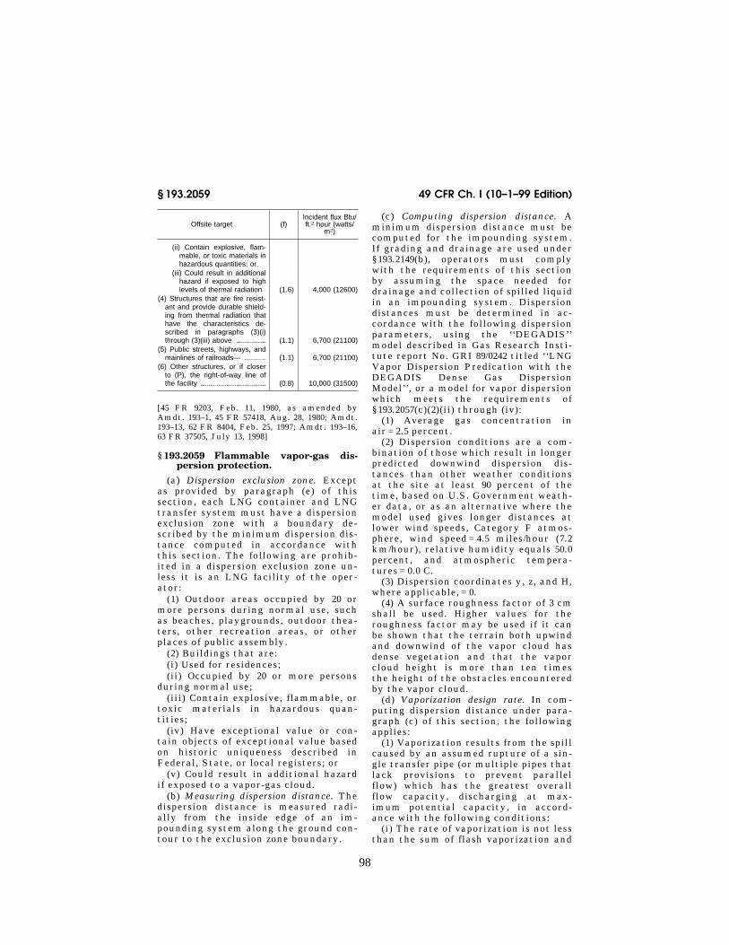
(d) Limiting values for incident radiantflux on offsite targets. The maximum in-cident radiant flux at an offsite targetfrom burning of a total spill in an im-pounding space must be limited to thedistances in paragraph (c) of this sec-tion using the following values of ‘‘(f)’’or ‘‘Incident Flux’’:
Offsite target (f)Incident flux Btu/ft.2 hour (watts/
m2)
(1) Outdoor areas occupied by20 or more persons during nor-mal use, such as beaches,playgrounds, outdoor theaters,other recreation areas or otherplaces of public assembly ....... (3) 1,600 (5047)
(2) Buildings that are used forresidences, or occupied by 20or more persons during normaluse ........................................... (1.6) 4,000 (12600)
(3) Buildings made of cellulosicmaterials or are not fire resist-ant or do not provide durableshielding from thermal radiationthat:
(i) Have exceptional value,or contain objects of ex-ceptional value based onhistoric uniqueness de-scribed in Federal, State,or local registers;.
VerDate 29<OCT>99 09:55 Nov 11, 1999 Jkt 183198 PO 00000 Frm 00097 Fmt 8010 Sfmt 8010 Y:\SGML\183198T.XXX pfrm02 PsN: 183198T
98
49 CFR Ch. I (10–1–99 Edition)§ 193.2059
Offsite target (f)Incident flux Btu/ft.2 hour (watts/
m2)
(ii) Contain explosive, flam-mable, or toxic materials inhazardous quantities; or.
(iii) Could result in additionalhazard if exposed to highlevels of thermal radiation (1.6) 4,000 (12600)
(4) Structures that are fire resist-ant and provide durable shield-ing from thermal radiation thathave the characteristics de-scribed in paragraphs (3)(i)through (3)(iii) above ............... (1.1) 6,700 (21100)
(5) Public streets, highways, andmainlines of railroads— ........... (1.1) 6,700 (21100)
(6) Other structures, or if closerto (P), the right-of-way line ofthe facility ................................. (0.8) 10,000 (31500)
[45 FR 9203, Feb. 11, 1980, as amended byAmdt. 193–1, 45 FR 57418, Aug. 28, 1980; Amdt.193–13, 62 FR 8404, Feb. 25, 1997; Amdt. 193–16,63 FR 37505, July 13, 1998]
§ 193.2059 Flammable vapor-gas dis-persion protection.
(a) Dispersion exclusion zone. Exceptas provided by paragraph (e) of thissection, each LNG container and LNGtransfer system must have a dispersionexclusion zone with a boundary de-scribed by the minimum dispersion dis-tance computed in accordance withthis section. The following are prohib-ited in a dispersion exclusion zone un-less it is an LNG facility of the oper-ator:
(1) Outdoor areas occupied by 20 ormore persons during normal use, suchas beaches, playgrounds, outdoor thea-ters, other recreation areas, or otherplaces of public assembly.
(2) Buildings that are:(i) Used for residences;(ii) Occupied by 20 or more persons
during normal use;(iii) Contain explosive, flammable, or
toxic materials in hazardous quan-tities;
(iv) Have exceptional value or con-tain objects of exceptional value basedon historic uniqueness described inFederal, State, or local registers; or
(v) Could result in additional hazardif exposed to a vapor-gas cloud.
(b) Measuring dispersion distance. Thedispersion distance is measured radi-ally from the inside edge of an im-pounding system along the ground con-tour to the exclusion zone boundary.
(c) Computing dispersion distance. Aminimum dispersion distance must becomputed for the impounding system.If grading and drainage are used under§ 193.2149(b), operators must complywith the requirements of this sectionby assuming the space needed fordrainage and collection of spilled liquidin an impounding system. Dispersiondistances must be determined in ac-cordance with the following dispersionparameters, using the ‘‘DEGADIS’’model described in Gas Research Insti-tute report No. GRI 89/0242 titled ‘‘LNGVapor Dispersion Predication with theDEGADIS Dense Gas DispersionModel’’, or a model for vapor dispersionwhich meets the requirements of§ 193.2057(c)(2)(ii) through (iv):
(1) Average gas concentration inair= 2.5 percent.
(2) Dispersion conditions are a com-bination of those which result in longerpredicted downwind dispersion dis-tances than other weather conditionsat the site at least 90 percent of thetime, based on U.S. Government weath-er data, or as an alternative where themodel used gives longer distances atlower wind speeds, Category F atmos-phere, wind speed=4.5 miles/hour (7.2km/hour), relative humidity equals 50.0percent, and atmospheric tempera-tures= 0.0 C.
(3) Dispersion coordinates y, z, and H,where applicable, = 0.
(4) A surface roughness factor of 3 cmshall be used. Higher values for theroughness factor may be used if it canbe shown that the terrain both upwindand downwind of the vapor cloud hasdense vegetation and that the vaporcloud height is more than ten timesthe height of the obstacles encounteredby the vapor cloud.
(d) Vaporization design rate. In com-puting dispersion distance under para-graph (c) of this section, the followingapplies:
(1) Vaporization results from the spillcaused by an assumed rupture of a sin-gle transfer pipe (or multiple pipes thatlack provisions to prevent parallelflow) which has the greatest overallflow capacity, discharging at max-imum potential capacity, in accord-ance with the following conditions:
(i) The rate of vaporization is not lessthan the sum of flash vaporization and
VerDate 29<OCT>99 09:55 Nov 11, 1999 Jkt 183198 PO 00000 Frm 00098 Fmt 8010 Sfmt 8010 Y:\SGML\183198T.XXX pfrm02 PsN: 183198T
99
Research and Special Programs Administration, DOT § 193.2061
vaporization from boiling by heattransfer from contact surfaces duringthe time necessary for spill detection,instrument response, and automaticshutdown by the emergency shutdownsystem, but not less than 10 minutes,plus, in the case of impounding sys-tems for LNG storage tanks with sideor bottom penetrations, the time nec-essary for the liquid level in the tankto reach the level of the penetration orequilibrate with the liquid impoundedassuming failure of the internal shutoffvalve.
(ii) In determining variations in thevaporization rate due to surface con-tact, the time necessary to wet 100 per-cent of the impounding floor area shallbe determined by equation C–9 in the1974 AGA report titled ‘‘Evaluation ofLNG Vapor Control Methods,’’ or byusing an equivalent personal computerprogram based on equation C–9 or byan alternative model which meets therequirements of § 193.2057(c)(2)(ii)through (iv).
(iii) After spill flow is terminated,the rate of vaporization is vaporizationof the remaining spillage, if any, fromboiling by heat transfer from contactsurfaces that are reducing in area andtemperature as a function of time.
(iv) Vapor detention space is allspace provided for liquid impoundmentand vapor detention outside the compo-nent served, less the volume occupiedby the spilled liquid at the time thevapor escapes the vapor detentionspace.
(2) The boiling rate of LNG on whichdispersion distance is based is deter-mined using the weighted averagevalue of the thermal properties of thecontact surfaces in the impoundingspace determined from eight represent-ative experimental tests on the mate-rials involved. If surfaces are insulated,the insulation must be designed, in-stalled, and maintained so that it willretain its performance characteristicsunder spill conditions.
(e) Planned vapor control. An LNG fa-cility need not have a dispersion exclu-sion zone if the Administrator findsthat compliance with paragraph (a) ofthis section would be impractical andthe operator prepares and follows aplan for controlling LNG vapor that isfound acceptable by the Administrator.
The plan must include circumstancesunder which LNG vapor is controlled topreclude the dispersion of a flammablemixture from the LNG facility underall predictable environmental condi-tions that could adversely affect con-trol. The reliability of the method ofcontrol must be demonstrated by test-ing or experience with LNG spills.
[45 FR 9203, Feb. 11, 1980, as amended byAmdt. 193–1, 45 FR 57418, Aug. 28, 1980; Amdt.193–13, 62 FR 8404, Feb. 25, 1997; Amdt. 193–15,63 FR 7723, Feb. 17, 1998; Amdt. 193–16, 63 FR37505, July 13, 1998]
§ 193.2061 Seismic investigation anddesign forces.
(a) Except for shop fabricated storagetanks of 70,000 gallons (265,000 liters) orless capacity mounted within 2 feet ofthe ground, if an LNG facility is lo-cated at a site in Zone 0 or 1 of the‘‘Seismic Risk Map of the UnitedStates,’’ UBC, each operator shall de-termine, based on a study of faults, hy-drologic regime, and soil conditions,whether a potential exists at the sitefor surface faulting or soil liquefaction.
(b) Subject to paragraph (f) of thissection, LNG facilities must be de-signed and built to withstand, withoutloss of structural or functional integ-rity, the following seismic designforces, as applicable:
(1) For LNG facilities (other thanshop fabricated storage tanks of 70,000gallons (265,000 liters) or less capacitymounted within 2 feet (610 millimeters)of the ground) located at a site in Puer-to Rico in Zone 2, 3, or 4 of the ‘‘Seis-mic Risk Map of the United States,’’ orat a site determined under paragraph(a) of this section to have a potentialfor surface faulting or soil liquefaction,the forces that could reasonably be ex-pected to occur at the foundation ofthe facility due to the most criticalground motion, motion amplification,permanent differential ground dis-placement, soil liquefaction, and sym-metric and asymmetric reaction forcesresulting from hydrodynamic pressureand motion of contained liquid ininteraction with the facility structure.
(2) For all other LNG facilities, thetotal lateral force set forth in UBC,Volume 1, corresponding to the zone ofthe ‘‘Seismic Risk Map of the UnitedStates’’ in which the facility is located,
VerDate 29<OCT>99 09:55 Nov 11, 1999 Jkt 183198 PO 00000 Frm 00099 Fmt 8010 Sfmt 8010 Y:\SGML\183198T.XXX pfrm02 PsN: 183198T

100
49 CFR Ch. I (10–1–99 Edition)§ 193.2061
and a vertical force equal to the totallateral force.
(c) Each operator of an LNG facilityto which paragraph (b)(1) of this sec-tion applies shall determine the seis-mic design forces on the basis of a de-tailed geotechnical investigation andin accordance with paragraphs (d) and(e) of this section. The investigationmust include each of the followingitems that could reasonably be ex-pected to affect the site and be suffi-cient in scope to identify all hazardsthat could reasonably be expected toaffect the facility design:
(1) Identification and evaluation offaults, Quaternary activity of thosefaults, tectonic structures, static anddynamic properties of materials under-lying the site, and, as applicable,tectonic provinces within 100 miles ofthe site;
(2) Identification and evaluation ofall historically reported earthquakeswhich could affect the determinationunder this section of the most criticalground motion or differential displace-ment at the site when correlated withparticular faults, tectonic structures,and tectonic provinces, as applicable;and
(3) Identification and evaluation ofthe hydrologic regime and the poten-tial of liquefaction-induced soil fail-ures.
(d) The most critical ground motionmust be determined in accordance withparagraph (e) of this section either:
(1) Probabilistically, when the avail-able earthquake data are sufficient toshow that the yearly probability of ex-ceedance of most critical ground mo-tion is 10¥4 or less; or
(2) Deterministically, when the avail-able earthquake data are insufficientto provide probabilistic estimates, withthe objective of determining a mostcritical ground motion with a yearlyprobability of exceedance of 10¥4 orless.
(e) The determination of most crit-ical ground motion, considering localand regional seismological conditions,must be made by using the following:
(1) A regionally appropriate attenu-ation relationship, assuming thatearthquakes occur at a location on afault, tectonic structure, or tectonicprovince, as applicable, which would
cause the most critical seismic move-ment at the site, except that whereepicenters of historically reportedearthquakes cannot be reasonably re-lated to known faults or tectonic struc-tures, but are recognized as being with-in a specific tectonic province which iswithin 100 miles (161 kilometers) of thesite, assume that those earthquakesoccur within their respective provincesat a source closest to the site.
(2) A horizontal design response spec-trum determined from the mean plusone standard deviation of a free-fieldhorizontal elastic response spectrawhose spectral amplitudes are con-sistent with values expected for themost critical ground motion.
(3) A vertical design response spec-trum that is either two-thirds of theamplitude of the horizontal design re-sponse spectrum at all frequencies orequal to the horizontal design responsespectrum where the site is locatedwithin 10 miles (16 kilometers) of theearthquake source.
(f) An LNG storage tank or its im-pounding system may not be located ata site where an investigation underparagraph (c) of this section shows thatany of the following conditions existsunless the Administrator grants an ap-proval for the site:
(1) The estimated design horizontalacceleration exceeds 0.8g at the tank ordike foundation.
(2) The specific local geologic andseismic data base is sufficient to pre-dict future differential surface dis-placement beneath the tank and dikearea, but displacement not exceeding 30inches (762 millimeters) cannot be as-sured with a high level of confidence.
(3) The specific local geologic andseismic data base is not sufficient topredict future differential surface dis-placement beneath the tank and dikearea, and the estimated cumulativedisplacement of a Quaternary faultwithin 1 mile (1.6 kilometers) of thetank foundation exceeds 60 inches (1.5meters).
(4) The potential for soil liquefactioncannot be accommodated by design andconstruction in accordance with para-graph (b)(1) of this section.
(g) An application for approval of asite under paragraph (f) of this sectionmust provide at least the following:
VerDate 29<OCT>99 09:55 Nov 11, 1999 Jkt 183198 PO 00000 Frm 00100 Fmt 8010 Sfmt 8010 Y:\SGML\183198T.XXX pfrm02 PsN: 183198T
101
Research and Special Programs Administration, DOT § 193.2067
(1) A detailed analysis and evaluationof the geologic and seismic characteris-tics of the site based on thegeotechnical investigation performedunder paragraph (c) of this section,with emphasis on prediction of near-field seismic response.
(2) The design plans and structuralanalysis for the tank, its impoundingsystem, and related foundations, with areport demonstrating that the designrequirements of this section are satis-fied, including any test results or otherdocumentation as appropriate.
(3) A description of safety-relatedfeatures of the site or designs, in addi-tion to those required by this part, ifapplicable, that would mitigate the po-tential effects of a catastrophic spill(e.g., remoteness or topographic fea-tures of the site, additional exclusiondistances, or multiple barriers for con-taining or impounding LNG).
(h) Each container which does nothave a structurally liquid-tight covermust have sufficient freeboard with anappropriate configuration to preventthe escape of liquid due to sloshing,wave action, and vertical liquid dis-placement caused by seismic action.
[45 FR 9203, Feb. 11, 1980, as amended byAmdt. 193–1, 45 FR 57419, Aug. 28, 1980; Amdt.193–16, 63 FR 37505, July 13, 1998]
§ 193.2063 Flooding.(a) Each operator shall determine the
effects of flooding on an LNG facilitysite based on the worst occurrence in a100-year period. The determinationmust take into account:
(1) Volume and velocity of the flood-water;
(2) Tsunamis (local, regional, and dis-tant);
(3) Potential failure of dams;(4) Predictable land developments
which would affect runoff accumula-tion of water; and
(5) Tidal action.(b) The effect of flooding determined
under paragraph (a) of this sectionmust be accommodated by location ordesign and construction, as applicable,to reasonably assure:
(1) The structural or functional in-tegrity of LNG facilities; and
(2) Access from outside the LNG fa-cility and movement of personnel andequipment about the LNG facility site
for the control of fire and other emer-gencies.
§ 193.2065 Soil characteristics.(a) Soil investigations including bor-
ings and other appropriate tests mustbe made at the site of each LNG facil-ity to determine bearing capacity, set-tlement characteristics, potential forerosion, and other soil characteristicsapplicable to the integrity of the facil-ity.
(b) The naturally occurring or de-signed soil characteristics at each LNGfacility site must provide load bearingcapacities, using appropriate safetyfactors, which can support the fol-lowing loads without excessive lateralor vertical movement that causes aloss of the functional or structural in-tegrity of the facility involved:
(1) Static loading caused by the facil-ity and its contents and any hydro-static testing of the facility; and
(2) Dynamic loading caused by move-ment of contents of the facility duringnormal operation, including flow,sloshing, and rollover.
§ 193.2067 Wind forces.(a) LNG facilities must be designed
to withstand without loss of structuralor functional integrity:
(1) The direct effect of wind forces;(2) The pressure differential between
the interior and exterior of a confining,or partially confining, structure; and
(3) In the case of impounding systemsfor LNG storage tanks, impact forcesand potential penetrations by windborne missiles.
(b) The wind forces at the location ofthe specific facility must be based onone of the following:
(1) For shop fabricated containers ofLNG or other hazardous fluids with acapacity of not more than 70,000 gal-lons (265,000 liters), applicable windload data in ASCE 7–88.
(2) For all other LNG facilities:(i) An assumed sustained wind veloc-
ity of not less than 200 miles (322 kilo-meters) per hour, unless the Adminis-trator finds a lower velocity is justifiedby adequate supportive data; or
(ii) The most critical combination ofwind velocity and duration, with re-spect to the effect on the structure,having a probability of exceedance in a
VerDate 29<OCT>99 09:55 Nov 11, 1999 Jkt 183198 PO 00000 Frm 00101 Fmt 8010 Sfmt 8010 Y:\SGML\183198T.XXX pfrm02 PsN: 183198T
102
49 CFR Ch. I (10–1–99 Edition)§ 193.2069
50-year period of 0.5 percent or less, ifadequate wind data are available andthe probabilistic methodology is reli-able.
[45 FR 9203, Feb. 11, 1980, as amended byAmdt. 193–1, 45 FR 57419, Aug. 28, 1980; 58 FR14522, Mar. 18, 1993; Amdt. 193–16, 63 FR 37505,July 13, 1998]
§ 193.2069 Other severe weather andnatural conditions.
(a) In addition to the requirements of§§ 193.2061, 193.2063, 193.2065, and 193.2067,each operator shall determine fromhistorical records and engineeringstudies the worst effect of other weath-er and natural conditions which maypredictably occur at an LNG facilitysite.
(b) The facility must be located anddesigned so that such severe conditionscannot reasonably be expected to re-sult in an emergency involving the fac-tors listed in § 193.2063(b).
§ 193.2071 Adjacent activities.
(a) Each operator shall determinethat present and reasonably foresee-able activities adjacent to an LNG fa-cility site that could adversely affectthe operation of the LNG facility orthe safety of persons or offsite prop-erty, if damage to the facility occurs.
(b) An LNG facility must not be lo-cated where present or projected offsiteactivities would be reasonably ex-pected to:
(1) Adversely affect the operation ofany of its safety control systems;
(2) Cause failure of the facility; or(3) Cause the facility not to meet the
requirements of this part.
§ 193.2073 Separation of facilities.
Each LNG facility site must be largeenough to provide for minimum separa-tions between facilities and between fa-cilities and the site boundary to:
(a) Permit movement of personnel,maintenance equipment, and emer-gency equipment around the facility;and
(b) Comply with distances specifiedin sections 2–2.4 through 2–2.7 of ANSI/NFPA 59A.
[45 FR 9203, Feb. 11, 1980, as amended at 58FR 14522, Mar. 18, 1993]
Subpart C—Design§ 193.2101 Scope.
This subpart prescribes requirementsfor the selection and qualification ofmaterials for components, and for thedesign and installation or constructionof components and buildings, includingseparate requirements for impoundingsystems, LNG storage tanks, and trans-fer systems.
MATERIALS
§ 193.2103 General.Materials for all components must
be—(a) Able to maintain their structural
integrity under all design loadings, in-cluding applicable environmental de-sign forces under subpart B of thispart;
(b) Physically, chemically, and ther-mally compatible within design limitswith any fluid or other materials withwhich they are in contact; and
(c) Qualified in accordance with theapplicable requirements of this sub-part.
§ 193.2105 Extreme temperatures: nor-mal operations.
Each operator shall—(a) Determine the range of tempera-
tures to which components will be sub-jected during normal operations, in-cluding required testing, initial start-up, cooldown operations, and shutdownconditions; and
(b) Use component materials thatmeet the design standards of this partfor strength, ductility, and other prop-erties throughout the entire range oftemperatures to which the componentwill be subjected in normal operations.
§ 193.2107 Extreme temperatures:emergency conditions.
(a) Each operator shall determine theeffects on components not normally ex-posed to extreme cold (including acomponent’s foundation or support sys-tem) of contact by LNG or cold refrig-erant that could result from error, aspill, or other emergency determinedas required by this part.
(b) Each operator shall determine theeffects on components (including theirfoundations or support systems) of the
VerDate 29<OCT>99 09:55 Nov 11, 1999 Jkt 183198 PO 00000 Frm 00102 Fmt 8010 Sfmt 8010 Y:\SGML\183198T.XXX pfrm02 PsN: 183198T
103
Research and Special Programs Administration, DOT § 193.2121
extreme heat which could result froman LNG or other hazardous fluid fire.
(c) Where the exposure determinedunder paragraph (a) or (b) of this sec-tion could result in a failure thatwould worsen the emergency, the com-ponent or its foundation or supportsystem, as appropriate, must be:
(1) Made of material or constructedto be suitable for the extreme tempera-ture to which it could be subjected; or
(2) Protected by insulation or othermeans that will delay failure due to ex-treme temperature in order to allowadequate time to take emergency re-sponses.
(d) If a material that has low resist-ance to flame temperatures is used inany component containing a hazardousfluid, the material must be protectedso that any heat resulting from a con-trollable emergency does not cause therelease of fluid that would result in anuncontrollable emergency.
§ 193.2109 Insulation.During normal operations, insulation
materials must:(a) Maintain insulating values;(b) Withstand thermal and mechan-
ical design loads; and(c) Be covered with a material that is
noncombustible in the installed state,is not subject to detrimental ultra-violet decay, and that can withstandthe forces of wind according to ASCE7–88 and anticipated loading whichcould occur in a controllable emer-gency.
[45 FR 9203, Feb. 11, 1980, as amended byAmdt. 193–1, 45 FR 57419, Aug. 28, 1980; 58 FR14522, Mar. 18, 1993]
§ 193.2111 Cold boxes.All cold boxes must be made of non-
combustible material and the insula-tion must be made of materials whichare noncombustible in the installedcondition.
§ 193.2113 Piping.(a) Piping made of cast iron, malle-
able iron, or ductile iron may not beused to carry any cryogenic or haz-ardous fluids.
(b) Piping materials intended for nor-mal use at temperatures below ¥28.9° C(¥20° F) or for use under § 193.2107(c)(1)must be qualified by testing in accord-
ance with ASME/ANSI B 31.3 to complywith § 193.2103(b).
[45 FR 9203, Feb. 11, 1980, as amended at 58FR 14522, Mar. 18, 1993]
§ 193.2115 Concrete subject to cryo-genic temperatures.
Concrete intended for normal use atcryogenic temperatures or for useunder § 193.2107(c)(1) may not be usedunless:
(a) Materials, measurements, mixing,placing, prestressing, and poststressingof concrete meets generally acceptedengineering practices;
(b) Metallic reinforcing, prestressingwire, structural and nonstructuralmembers used in concrete are accept-able in the installed condition for thetemperature and stress levels encoun-tered at design loading conditions; and
(c) Tests for the compressivestrength, the coefficient of contrac-tion, an acceptable thermal gradient,and, if applicable, acceptable surfaceloading to prevent detrimental spallingare performed on the concrete at thelowest temperature for which the con-crete is designed or similar test dataon these properties are available.
§ 193.2117 Combustible materials.Combustible materials are not per-
mitted for the construction of build-ings, plant equipment, and the founda-tions and supports of buildings andplant equipment in areas where igni-tion of the material would worsen anemergency. However, limited combus-tible materials may be used when theuse of noncombustible materials is im-practical.
§ 193.2119 RecordsEach operator shall keep a record of
all materials for components, build-ings, foundations, and support systems,as necessary to verify that materialproperties meet the requirements ofthis part. These records must be main-tained for the life of the item con-cerned.
DESIGN OF COMPONENTS AND BUILDINGS
§ 193.2121 General.Components, including their founda-
tions and support systems, must be de-signed, fabricated, and installed to
VerDate 29<OCT>99 09:55 Nov 11, 1999 Jkt 183198 PO 00000 Frm 00103 Fmt 8010 Sfmt 8010 Y:\SGML\183198T.XXX pfrm02 PsN: 183198T
104
49 CFR Ch. I (10–1–99 Edition)§ 193.2123
withstand, without loss of functionalor structural integrity, predictableloadings not including environmentaldesign forces under subpart B of thispart unless applicable under that sub-part.
§ 193.2123 Valves.(a) Each valve, including control
valves and relief valves, must be de-signed, manufactured, and tested tocomply with ASME/ANSI B31.3 orASME/ANSI B31.5 or ASME/ANSI B31.8or API Standard 6D, if design condi-tions fall within their scope.
(b) Extended bonnet valves must beused for service temperatures below¥45.6° C (¥50° F).
(c) Valves used for cryogenic liquidservice must be designed to operate inthe position in which they are in-stalled.
(d) Powered local and remote oper-ation must be provided for valves in-tended for use during a controllableemergency that would be difficult orexcessively time-consuming to operatemanually during such an emergency.
(e) Valves must be designed and in-stalled so that an excessive load on thepiping system does not render thevalve inoperable.
[45 FR 9203, Feb. 11, 1980, as amended byAmdt. 193–1, 45 FR 57419, Aug. 28, 1980; 58 FR14522, Mar. 18, 1993]
§ 193.2125 Automatic shutoff valves.Each automatic shutoff valve or com-
bination of valves must:(a) Have a fail-safe design;(b) Operate to stop fluid flow which
would endanger the operational integ-rity of plant equipment; and
(c) Close at a rate to avoid fluid ham-mer which would endanger the oper-ating integrity of a component.
§ 193.2127 Piping.(a) Piping must be designed, manu-
factured, and tested to comply withASME/ANSI B 31.3.
(b) All cryogenic and hazardous fluidpiping must have connections to facili-tate blowdown and purge as requiredby this part.
(c) Each cryogenic or hazardous fluidpiping system that is aboveground
must be identified by color coding,painting, or labeling.
(d) Seamless pipe or pipe with a lon-gitudinal joint efficiency of 1.0 deter-mined in accordance with ASME/ANSIB31.3, or pipe with a design pressureless than two-thirds of the mill-prooftest pressure or subsequent shop orfield hydrostatic test pressure must beused for process and transfer pipinghandling cryogenic or other hazardousfluids with a service temperature below¥22° F (¥30° C).
(e) For longitudinal or spiral weldpiping handling LNG or cryogenicfluids, the heat affected zone mustcomply with section 323.2.2 of ASME/ANSI B31.3.
(f) Threaded piping used in hazardousfluid service must be at least Schedule80.
[45 FR 9203, Feb. 11, 1980, as amended at 58FR 14522, Mar. 18, 1993]
§ 193.2129 Piping attachments andsupports.
Piping attachments and supports forLNG or refrigerant piping must be de-signed to prevent excessive heat trans-fer which can result in either uninten-tional restraint of piping caused by iceformations or the embrittlement ofsupporting steel.
§ 193.2131 Building design.
(a) Each building or structural enclo-sure in which potentially hazardousquantities of flammable materials arehandled must be designed and con-structed to minimize fire hazards.
(b) Buildings or structural enclosuresin which hazardous or cryogenic fluidsare handled shall be of light-weight,noncombustible construction withnonload-bearings walls.
(c) If rooms containing such fluidsare located within or attached to build-ings in which such fluids are not han-dled, i.e., control rooms, shops, etc.,the common walls shall be limited tonot more than two in number, shall bedesigned to withstand a static pressureof at least 4800 Pa (100 psf), have nodoors or other communicating open-ings, and shall have a fire resistancerating of at least 1 hour.
VerDate 29<OCT>99 09:55 Nov 11, 1999 Jkt 183198 PO 00000 Frm 00104 Fmt 8010 Sfmt 8010 Y:\SGML\183198T.XXX pfrm02 PsN: 183198T
105
Research and Special Programs Administration, DOT § 193.2143
§ 193.2133 Buildings: ventilation.
(a) Each building in which poten-tially hazardous quantities of flam-mable fluids are handled must be venti-lated to minimize the possibility, dur-ing normal operation, of hazardous ac-cumulation of a flammable gas and airmixture, hazardous products of com-bustion, and other hazardous vapors inenclosed process areas by one of thefollowing means:
(1) A continuously operating mechan-ical ventilation system;
(2) A combination gravity ventilationsystem and normally off mechanicalventilation system which is activatedby suitable flammable gas detectors ata concentration not exceeding 25 per-cent of the lower flammable limit ofthe gas;
(3) A dual rate mechanical ventila-tion system with the high rate acti-vated by suitable flammable gas detec-tors at a concentration not exceeding25 percent of the lower flammable limitof the gas; or
(4) A gravity ventilation system com-posed of a combination of wall open-ings, roof ventilators, and, if there arebasements or depressed floor levels, asupplemental mechanical ventilationsystem.
(b) The ventilation rate must be atleast 1 cubic foot (.035 cubic meters)per minute of air per square foot (persquare meter) of floor area. If vaporsheavier than air can be present, theventilation must be proportioned ac-cording to the area of each level.
[45 FR 9203, Feb. 11, 1980, as amended byAmdt. 193–16, 63 FR 37505, July 13, 1998]
§ 193.2135 Expansion or contraction.
Each operator shall consider theamount of contraction and expansionof each component during operatingand environmental thermal cycling andshall:
(a) Provide components that operatewithout detrimental stress or restric-tion of movement, within each compo-nent and between components, causedby contraction and expansion; and
(b) Prevent ice buildup from det-rimentally restricting the movementof components caused by contractionand expansion.
§ 193.2137 Frost heave.
(a) Each operator shall:(1) Determine which components and
their foundations could be endangeredby frost heave from ambient tempera-tures or operating temperatures of thecomponent; and
(2) Provide protection against frostheave which might impair their struc-tural integrity.
(b) For each component and founda-tion determined under paragraph (a) ofthis section, instrumentation must beinstalled to warn of potential struc-tural impairment due to frost heave,unless the operator includes in themaintenance procedures required bythis part, a method and schedule of in-spection that will detect changes in theelevation.
§ 193.2139 Ice and snow.
(a) Components must be designed tosupport the weight of ice and snowwhich could normally collect or formon them.
(b) Each operator shall provide pro-tection for components from falling iceor snow which may accumulate onstructures.
(c) Valves and moving componentsmust not become inoperative due to iceformation on the component.
§ 193.2141 Electrical systems.
(a) Each operator shall select and in-stall electrical equipment and wiringfor components in accordance withANSI/NFPA 70 and, where applicable,section 7–6.2 of ANSI/NFPA 59A.
(b) Electrical grounding and bondingmust be in accordance with section 7–7.1.1 of ANSI/NFPA 59A.
(c) Protective measures for stray orimpressed currents must be provided inaccordance with section 7–7.3 of ANSI/NFPA 59A.
[58 FR 14522, Mar. 18, 1993]
§ 193.2143 Lightning.
Each operator shall install propergrounds as necessary to minimize thehazard to plant personnel and compo-nents, including all electrical circuits,as a result of lightning.
VerDate 29<OCT>99 09:55 Nov 11, 1999 Jkt 183198 PO 00000 Frm 00105 Fmt 8010 Sfmt 8010 Y:\SGML\183198T.XXX pfrm02 PsN: 183198T
106
49 CFR Ch. I (10–1–99 Edition)§ 193.2145
§ 193.2145 Boilers and pressure ves-sels.
Boilers must be designed and fab-ricated in accordance with section I orsection IV of the ASME Boiler andPressure Vessel Code. Other pressurevessels subject to that Code must bedesigned and fabricated in accordancewith Division 1 or Division 2 of sectionVIII.
§ 193.2147 Combustion engines andturbines.
Combustion engines and gas turbinesmust be installed in accordance withANSI/NFPA–37.
[45 FR 9203, Feb. 11, 1980, as amended at 58FR 14522, Mar. 18, 1993]
IMPOUNDMENT DESIGN AND CAPACITY
§ 193.2149 Impoundment required.(a) An impounding system must be
provided for storage tanks to contain apotential spill of LNG or other haz-ardous liquid.
(b) Grading or drainage or an im-pounding system must be provided toensure that accidental spills or leaksfrom the following components andareas do not endanger components oradjoining property or enter navigablewaterways:
(1) Liquefaction and other processequipment;
(2) Vaporizers;(3) Transfer systems;(4) Parking areas for tank cars or
tank trucks; and(5) Areas for loading, unloading, or
storing portable containers and dewarvessels.
(c) Impounding systems for LNGmust be designed and constructed inaccordance with this subpart. Im-pounding systems intended for contain-ment of hazardous liquids other thanLNG must meet the requirements ofANSI/NFPA–30.
[45 FR 9203, Feb. 11, 1980, as amended at 58FR 14522, Mar. 18, 1993]
§ 193.2151 General design characteris-tics.
(a) An impounding system must havea configuration or design which, to themaximum extent possible, will preventliquid from escaping impoundment by
leakage, splash from collapse of astructure or part thereof, momentumand low surface friction, foaming, fail-ure of pressurized piping, and acci-dental pumping.
(b) The basic form of an impoundingsystem may be excavation, a naturalgeological formation, manufactureddiking, such as berms or walls, or anycombination thereof.
§ 193.2153 Classes of impounding sys-tems.
(a) For the purpose of this part, im-pounding systems are classified as fol-lows:
Class 1. A system which surrounds the com-ponent served with the inner surface of thedike constructed against or within 24 inches(610 millimeters) of the component served.
Class 2. A system which surrounds the com-ponent or area served with the dike locateda distance away from the component or atthe periphery of the area.
Class 3. A system which conducts a spill bydikes and floors to a remote impoundingspace which does not surround the compo-nent or area served.
(b) In the case of an impounding sys-tem consisting of a combination ofclasses, requirements of this part re-garding a single class apply accordingto the percentage of impoundment pro-vided by each class.
[45 FR 9203, Feb. 11, 1980, as amended byAmdt. 193–16, 63 FR 37505, July 13, 1998]
§ 193.2155 Structural requirements.(a) Subject to paragraph (b) of this
section, the structural parts of an im-pounding system must be designed andconstructed to prevent impairment ofthe system’s performance reliabilityand structural integrity as a result ofthe following:
(1) The imposed loading from—(i) Full hydrostatic head of im-
pounded LNG;(ii) Hydrodynamic action, including
the effect of any material injected intothe system for spill control;
(iii) The impingement of the trajec-tory of an LNG jet discharged at anypredictable angle; and
(iv) Anticipated hydraulic forcesfrom a credible opening in the compo-nent or item served, assuming that thedischarge pressure equals design pres-sure.
VerDate 29<OCT>99 09:55 Nov 11, 1999 Jkt 183198 PO 00000 Frm 00106 Fmt 8010 Sfmt 8010 Y:\SGML\183198T.XXX pfrm02 PsN: 183198T
107
Research and Special Programs Administration, DOT § 193.2167
(2) The erosive action from a spill, in-cluding jetting of spilling LNG, andany other anticipated erosive actionincluding surface water runoff, ice for-mation, dislodgement of ice formation,and snow removal.
(3) The effect of the temperature, anythermal gradient, and any other antici-pated degradation resulting from sud-den or localized contact with LNG.
(4) Exposure to fire from impoundedLNG or from sources other than im-pounded LNG.
(5) If applicable, the potential impactand loading on the dike due to—
(i) Collapse of the component or itemserved or adjacent components; and
(ii) If the LNG facility adjoins theright-of-way of any highway or rail-road, collision by or explosion of atrain, tank car, or tank truck thatcould reasonably be expected to causethe most severe loading.
(b) For spills from LNG storage tankswith Class 2 or 3 impounding systems,imposed loading and surging flow char-acteristics must be based on a crediblerelease of the tank contents.
(c) If an LNG storage tank is locatedwithin a horizontal distance of 6,100 m.(20,000 ft.) from the nearest point of thenearest runway serving large aircraftas defined in 14 CFR part 1.1, a Class 1impounding system must be used whichis designed to withstand collision by,or explosion of, the heaviest aircraftwhich can take off or land at the air-port.
§ 193.2157 Coatings and coverings.Insulation, sealants, or other coat-
ings and coverings which are part of animpounding system—
(a) Must be noncombustible in an in-stalled condition when exposed to anLNG fire resulting from a spill thatcovers the floor of the impoundingspace;
(b) Must withstand exposure to firefrom sources determined as required bythis part, other than impounded LNG,for a period of time until fire protec-tive or fire extinguishing action istaken; and
(c) When used for the purpose ofmaintaining the functional integrity ofan impounding system, must be capa-ble of withstanding sudden exposure toLNG without loss of such integrity.
§ 193.2159 Floors.Floors of Class 2 and Class 3 im-
pounding systems must, to the extentfeasible—
(a) Slope away from the componentor item impounded and to a sump basininstalled under § 193.2171;
(b) Slope away from the nearest adja-cent component;
(c) Drain surface waters from thefloor at rates based on a storm of 10-year frequency and 1-hour duration andother natural water sources; and
(d) Be designed to minimize thewetted floor area.
§ 193.2161 Dikes, general.(a) Penetrations in dikes to accom-
modate piping or any other purpose areprohibited.
(b) An outer wall of a componentserved by an impounding system maynot be used as a dike except for a con-crete wall designed to comply with therequirements of § 193.2155(c) or equiva-lent design impact loading.
§ 193.2163 Vapor barriers.If vapor barriers are installed in
meeting the requirements of § 193.2059,they must be designed and constructedto detain LNG vapor.
§ 193.2165 Dike dimensions.In addition to dike dimensions need-
ed to comply with other requirementsof this subpart, to minimize the possi-bility that a trajectory of accidentallydischarged liquid would pass over thetop of a dike, the horizontal distancefrom the inner wall of the componentor vessel served to the closest insideedge of the top of the dike must atleast equal the vertical distance fromthe maximum liquid level in the com-ponent or vessel to the inside edge ofthe top of the dike.
[45 FR 9203, Feb. 11, 1980, as amended byAmdt. 193–1, 45 FR 57419, Aug. 28, 1980]
§ 193.2167 Covered systems.(a) A covered impounding system is
prohibited unless it is—(1) Sealed from the atmosphere and
filled with an inert gas; or(2) Permanently interconnected with
the vapor space of the componentserved.
VerDate 29<OCT>99 09:55 Nov 11, 1999 Jkt 183198 PO 00000 Frm 00107 Fmt 8010 Sfmt 8010 Y:\SGML\183198T.XXX pfrm02 PsN: 183198T
108
49 CFR Ch. I (10–1–99 Edition)§ 193.2169
(b) Flammable nonmetallic membra-nous covering is prohibited in a cov-ered system.
(c) For systems to which paragraph(a)(1) of this section applies, instru-mentation and controls must be pro-vided to—
(1) Maintain pressures at a safe level;and
(2) Monitor gas concentrations in ac-cordance with § 193.2169.
(d) Dikes must have adequate struc-tural strength to assure that they canwithstand impact from a collapsedcover and all anticipated conditionswhich could cause a failure of the im-pounding space cover.
§ 193.2169 Gas leak detection.
Appropriate areas within an im-pounding system where collection orpassage of LNG or LNG vapor could beexpected must be equipped with sens-ing and warning devices to monitorcontinuously for the presence of LNGor LNG vapor and to warn before LNGgas concentration levels exceed 25 per-cent of the lower flammable limit.
§ 193.2171 Sump basins.
Except for Class 1 impounding sys-tems, a sump basin must be located ineach impounding system for collectionof water.
§ 193.2173 Water removal.
(a) Except for Class 1 systems, im-pounding systems must have sumppumps and piping running over thedike to remove water collecting in thesump basin.
(b) The water removal system musthave adequate capacity to removewater at rates which equal the max-imum predictable collection rate froma storm of 10-year frequency and 1-hourduration, and other natural causes.
(c) Sump pumps for water removalmust—
(1) Be operated as necessary to keepthe impounding space as dry as prac-tical; and
(2) If sump pumps are designed forautomatic operation, have redundantautomatic shutdown controls to pre-vent operation when LNG is present.
§ 193.2175 Shared impoundment.
When an impounding system servesmore than one LNG storage tank, ameans must be provided to prevent lowtemperature or fire resulting fromleakage from any one of the storagetanks served causing any other storagetank to leak. The means must not re-sult in a vapor dispersion distancewhich exceeds the exclusion zone re-quired by § 193.2059.
[Amdt. 193–1, 45 FR 57419, Aug. 28, 1980]
§ 193.2179 Impoundment capacity: gen-eral.
In addition to capacities otherwiserequired by this subpart, an impound-ing system must have sufficient volu-metric capacity to provide for—
(a) Displacement by the component,tank car, tank truck, container, ordewar vessel served; and
(b) Where applicable, displacementwhich could occur when a higher den-sity substance than the liquid to be im-pounded enters the system, consideringall relevant means of assuring capac-ity.
§ 193.2181 Impoundment capacity:LNG storage tanks.
(a) Except as provided in paragraph(b) of this section, each impoundingsystem serving an LNG storage tankmust have a minimum volumetric liq-uid impoundment capacity as follows:
Number of tanks insystem
Class or type ofsystem
System capacity inpercent of LNGtank’s maximumliquid capacity
1 ............................ Class 1 ................. 110 percent.Classes 2 and 3 ... 150 percent.
More than 1 .......... Classes 2 and 3 ... 100 percent of alltanks or 150percent of larg-est tank, which-ever is greater.
(b) For purposes of this section, acovered impounding system serving asingle LNG storage tank may have acapacity of 110 percent of the LNGtank’s maximum liquid capacity if it iscovered by a roof that is separate andindependent from the LNG storagetank.
VerDate 29<OCT>99 09:55 Nov 11, 1999 Jkt 183198 PO 00000 Frm 00108 Fmt 8010 Sfmt 8010 Y:\SGML\183198T.XXX pfrm02 PsN: 183198T

109
Research and Special Programs Administration, DOT § 193.2193
§ 193.2183 Impoundment capacity:equipment and transfer systems.
If an impounding system serves acomponent under § 193.2149(b) (1)–(3), itmust have a minimum volumetric liq-uid impoundment capacity equal to thesum of—
(a) One-hundred percent of the vol-ume of liquid that could be containedin the component and, where applica-ble, tank car or tank truck served; and
(b) The maximum volume of liquidwhich could discharge into the im-pounding space from any single failureof equipment or piping during the timeperiod necessary for spill detection, in-strument response, and sequencedshutdown by the automatic shutdownsystem under § 193.2439.
§ 193.2185 Impoundment capacity:parking areas, portable containers.
Each impounding system serving anarea listed under § 193.2149(b) (4) or (5)must have a minimum volumetric liq-uid impoundment capacity which com-plies with the requirements of§ 193.2181, assuming each tank car, tanktruck, portable container, or dewarvessel to be a storage tank.
LNG STORAGE TANKS
§ 193.2187 General.
(a) LNG storage tanks must complywith the requirements of this subpartand the other applicable requirementsof this part.
(b) A flammable nonmetallic mem-brane liner may not be used as an innercontainer in a storage tank.
§ 193.2189 Loading forces.
Each part of an LNG storage tankmust be designed to withstand withoutloss of functional or structural integ-rity any predictable combination offorces which would result in the high-est stress to the part, including the fol-lowing:
(a) Internal design pressure deter-mined under § 193.2197.
(b) External design pressure deter-mined under § 193.2199.
(c) Weight of the structure.(d) Weight of liquid to be stored, ex-
cept that in no case will the density as-sumed be less than 29.3 pounds per
cubic foot (470 kilograms per cubicmeter).
(e) Loads due to testing required by§ 193.2327.
(f) Nonuniform reaction forces on thefoundation due to predictable settlingand other movement.
(g) Superimposed forces from piping,stairways, and other connected appur-tenances.
(h) Predictable snow and ice loads.(i) The loading of internal insulation
on the inner container and outer shelldue to compaction and movement ofthe container and shell over the designlife of the insulation.
(j) In the case of vacuum insulation,the forces due to the vacuum.
(k) In the case of a positive pressurepurge, the forces due to the maximumpositive pressure of the purge gas.
§ 193.2191 Stratification.LNG storage tanks with a capacity of
5,000 barrels (795 cubic meters) or moremust be equipped with means to miti-gate a potential for rollover and over-pressure such as:
(a) Selective filling at the top andbottom of the tank;
(b) Circulating liquid from the bot-tom to the top of the same tank; or
(c) Transferring liquid selectivelyfrom the bottom of the tank to the bot-tom or top of any adjacent storagetank.
[45 FR 9203, Feb. 11, 1980, as amended byAmdt. 193–16, 63 FR 37505, July 13, 1998]
§ 193.2193 Movement and stress.(a) Each operator shall determine for
normal operations of each LNG storagetank—
(1) The amount and pattern of pre-dictable movement of components, in-cluding transfer piping, and the foun-dation, which could result from ther-mal cycling, loading forces, and ambi-ent air changes; and
(2) For a storage tank with an innercontainer, the predictable movement ofthe inner container and the outer shellin relation to each other.
(b) Storage tanks must be designedto provide adequate allowance forstress due to movement determinedunder paragraph (a) of this section, in-cluding provisions that—
VerDate 29<OCT>99 09:55 Nov 11, 1999 Jkt 183198 PO 00000 Frm 00109 Fmt 8010 Sfmt 8010 Y:\SGML\183198T.XXX pfrm02 PsN: 183198T
110
49 CFR Ch. I (10–1–99 Edition)§ 193.2195
(1) Backfill does not cause excessivestresses on the tank structure due toexpansion of the storage tank duringwarmup;
(2) Insulation does not settle to adamaging degree or unsafe conditionduring thermal cycling; and
(3) Expansion bends and other expan-sion or contraction devices are ade-quate to prevent excessive stress ontank penetrations, especially duringcooldown from ambient temperatures.
§ 193.2195 Penetrations.(a) All penetrations in an LNG stor-
age tank must be designed in accord-ance with API 620, including appendixQ.
(b) The loadings on all penetrationsmust be determined by an analysis ofall contributing forces, including thosefrom tank thermal movements, con-necting piping thermal movements, hy-draulic forces, applicable wind andearthquake forces, and the forces re-sulting from settlement or movementof the tank foundation or pipe sup-ports.
(c) All penetrations in an LNG stor-age tank below the design liquid levelmust be fitted with an internal shutoffvalve which is designed and installed sothat any failure of the nozzle pene-trating the tank will be outside thetank.
(d) The requirements of paragraphs(a) and (c) of this section do not applyto shop fabricated tanks of 70,000 gal-lons (265,000 liters) or less capacity. Allpenetrations in such tanks must be de-signed and installed in accordance withthe applicable provisions of sectionVIII, Division 1 of the ASME Boiler andPressure Vessel Code.
[45 FR 9203, Feb. 11, 1980, as amended byAmdt. 193–16, 63 FR 37505, July 13, 1998]
§ 193.2197 Internal design pressure.(a) Each operator shall establish the
internal design pressure at the top ofeach LNG storage tank, including asuitable margin above the maximumallowable working pressure.
(b) The internal design pressure of astorage tank may not be lower thanthe highest pressure in the vapor spaceresulting from each of the followingevents or combination thereof that pre-dictably might occur, giving consider-
ation to vapor handling equipment, re-lief devices in accordance with§ 193.2429, and any other mitigatingmeasures:
(1) Filling the tank with LNG includ-ing effects of increased vaporizationrate due to superheat and sensible heatof the added liquid;
(2) Rollover;(3) Fall in barometric pressure, using
the worst combination of amount offall and rate of fall which might pre-dictably occur;
(4) Loss of effective insulation thatmay result from an adjacent fire, leakof liquid into the intertank space, orother predictable accident; and
(5) Flash vaporization resulting frompump recirculation.
§ 193.2199 External design pressure.
(a) Each operator shall establish theexternal design pressure at the top ofeach LNG storage tank, including asuitable margin below the minimumallowable working pressure.
(b) The external design pressure maynot be higher than the lowest vaporpressure in the vapor space resultingfrom each of the following events orcombinations thereof that predictablymight occur, giving consideration togas makeup systems, vacuum relief de-vices in accordance with § 193.2429, andany other mitigating measures.
(1) Withdrawing liquid from the tank;(2) Withdrawing gas from the tank;(3) Adding subcooled LNG to the
tank; and(4) Rise in barometric pressure, based
on the worst combination of amount ofrise and rate of rise which predictablymight occur.
§ 193.2201 Internal temperature.
The liquid container of each LNGstorage tank and all tank parts used incontact with LNG or its cold vaporshall be designed for the lowest bulkliquid temperature which can be at-tained in the LNG storage tank.
§ 193.2203 Foundation.
(a) Each LNG storage tank musthave a stable foundation designed inaccordance with generally acceptedstructural engineering practices.
VerDate 29<OCT>99 09:55 Nov 11, 1999 Jkt 183198 PO 00000 Frm 00110 Fmt 8010 Sfmt 8010 Y:\SGML\183198T.XXX pfrm02 PsN: 183198T
111
Research and Special Programs Administration, DOT § 193.2215
(b) Each foundation must support de-sign loading forces without detri-mental settling that could impair thestructural integrity of the tank.
§ 193.2205 Frost heave.
If the protection provided for LNGstorage tank foundations from frostheave under § 193.2137(a) includes heat-ing the foundation area—
(a) An instrumentation and alarmsystem must be provided to warn ofmalfunction of the heating system; and
(b) A means to correct the malfunc-tion must be provided.
§ 193.2207 Insulation.
(a) Insulation on the outside of theouter shell of an LNG storage tankmay not be used to maintain storedLNG at an operating temperature dur-ing normal operation.
(b) Insulation between an inner con-tainer and the outer shell of an LNGstorage tank must—
(1) Be compatible with the containedliquid and its vapor;
(2) In its installed condition, be non-combustible; and
(3) Not significantly lose insulatingproperties by melting, settling, orother means due to a fire resultingfrom a spill that covers the floor of theimpounding space around the tank.
§ 193.2209 Instrumentation for LNGstorage tanks.
(a) Each LNG storage tank having acapacity over 70,000 gallons (265,000 li-ters) must be equipped with a sufficientnumber of sensing devices and per-sonnel warning devices, as prescribed,which operate continuously while thetank is in operation to assure thateach of the following conditions is nota potential hazard to the structural in-tegrity or safety of the tank:
Condition Instrumentation
(1) Amount of liquidin the tank.
Redundant liquid level gages and re-corders with high level alarms, anda minimum of one independent highlevel alarm.
(2) Vapor pressurewithin the tank.
Redundant gages and recorders withhigh and low pressure alarms.
(3) Temperatures atrepresentative crit-ical points in thefoundation.
Temperature indicating and recordingdevices with alarm.
Condition Instrumentation
(4) Temperature ofcontained liquid atvarious vertical in-tervals.
Temperature recorders.
(5) Abnormal tem-perature in tankstructure.
Thermocouples located at representa-tive critical points with recorders.
(6) Excessive relativemovement of innercontainer andouter shell.
Linear and rotational movement indi-cators located between inner con-tainer and outer shell with record-ers.
(b) LNG storage tanks with a capac-ity of 70,000 gallons (265,000 liters) orless must be equipped with the fol-lowing:
(1) LNG liquid trycocks, when at-tended during the filling operation.
(2) Pressure gages and recorders withhigh pressure alarm.
(3) Differential pressure liquid levelgage.
(c) Each storage tank must be de-signed as appropriate to provide forcompliance with the inspection re-quirements of this part.
[45 FR 9203, Feb 11., 1980, as amended byAmdt. 193–16, 63 FR 37505, July 13, 1998]
§ 193.2211 Metal storage tanks.(a) Metal storage tanks with internal
design pressures of not more than 15psi (103 kPa) gage must be designed andconstructed in accordance with APIStandard 620 and, where applicable, ap-pendix Q of that standard.
(b) Metal storage tanks with internaldesign pressures above 15 psi (103 kPa)gage must be designed in accordancewith the applicable division of sectionVIII of the ASME Boiler and PressureVessel Code.
[45 FR 9203, Feb. 11, 1980, as amended byAmdt. 193–16, 63 FR 37505, Juy 13, 1998]
§ 193.2213 Concrete storage tanks.Concrete storage tanks must be de-
signed and constructed in accordancewith section 4–3 of ANSI/NFPA–59A.
[45 FR 9203, Feb. 11, 1980, as amended at 58FR 14522, Mar. 18, 1993]
§ 193.2215 Thermal barriers.Thermal barriers must be provided
between piping and an outer shell whennecessary to prevent the outer shellfrom being exposed during normal op-eration to temperatures lower than itsdesign temperature.
VerDate 29<OCT>99 09:55 Nov 11, 1999 Jkt 183198 PO 00000 Frm 00111 Fmt 8010 Sfmt 8010 Y:\SGML\183198T.XXX pfrm02 PsN: 183198T
112
49 CFR Ch. I (10–1–99 Edition)§ 193.2217
§ 193.2217 Support system.
(a) Saddles and legs must be designedin accordance with generally acceptedstructural engineering practices, tak-ing into account loads during transpor-tation, erection loads, and thermalloads.
(b) Storage tank stress concentra-tions from support systems must beminimized by distribution of loadsusing pads, load rings, or other means.
(c) For a storage tank with an innercontainer, support systems must be de-signed to—
(1) Minimize thermal stresses im-parted to the inner container and outershell from expansion and contraction;and
(2) Sustain the maximum applicableloading from shipping and operatingconditions.
(d) LNG storage tanks with an airspace beneath the tank bottom or itsfoundation must be designed to with-stand without loss of functional orstructural integrity, the forces causedby the ignition of a combustible vaporcloud in this space.
§ 193.2219 Internal piping.
Piping connected to an inner con-tainer that is located in the space be-tween the inner container and outershell must be designed for not less thanthe pressure rating of the inner con-tainer. The piping must contain expan-sion loops where necessary to protectagainst thermal and other secondarystresses created by operation of thetank. Bellows may not be used withinthe space between the inner containerand outer shell.
§ 193.2221 Marking.
(a) Each operator shall install andmaintain a name plate in an accessibleplace on each storage tank and mark itin accordance with the applicable codeor standard incorporated by referencein § 193.2211 or § 193.2213.
(b) Each penetration in a storagetank must be marked indicating thefunction of the penetration.
(c) Marking required by this sectionmust not be obscured by frosting.
DESIGN OF TRANSFER SYSTEMS
§ 193.2223 General.
(a) Transfer systems must complywith the requirements of this subpartand other applicable requirements ofthis part.
(b) The design of transfer systemsmust provide for stress due to the fre-quency of thermal cycling and inter-mittent use to which the transfer sys-tem may be subjected.
(c) Slip type expansion joints are pro-hibited and packing-type joints maynot be used in transfer systems forLNG or flammable refrigerants.
(d) A suitable means must be pro-vided to precool the piping in a mannerthat prevents excessive stress prior tonormal transfer of cold fluids.
(e) Stresses due to thermal and hy-draulic shock in the piping systemmust be determined and accommodatedby design to avoid damage to piping.
§ 193.2227 Backflow.
(a) Each transfer system must oper-ate with a means to—
(1) Prevent backflow of liquid from areceiving container, tank car, or tanktruck from causing a hazardous condi-tion; and
(2) Maintain one-way flow where nec-essary for the integrity or safe oper-ation of the LNG facility.
(b) The means provided under para-graph (a)(1) of this section must be lo-cated as close as practical to the pointof connection of the transfer systemand the receiving container, tank car,or tank truck.
§ 193.2229 Cargo transfer systems.
(a) Each cargo transfer system musthave—
(1) A means of safely depressurizingand venting that system before dis-connection;
(2) A means to provide for safe vapordisplacement during transfer;
(3) Transfer piping, pumps, and com-pressors located or protected by suit-able barriers so that they are safe fromdamage by tank car or tank truckmovements;
(4) A signal light at each control lo-cation or remotely located pumps or
VerDate 29<OCT>99 09:55 Nov 11, 1999 Jkt 183198 PO 00000 Frm 00112 Fmt 8010 Sfmt 8010 Y:\SGML\183198T.XXX pfrm02 PsN: 183198T

113
Research and Special Programs Administration, DOT § 193.2305
compressors used for transfer which in-dicates whether the pump or com-pressor is off or in operation; and
(5) A means of communication be-tween loading or unloading areas andother areas in which personnel are as-sociated with the transfer operations.
(b) Hoses and arms for cargo transfersystems must be designed as follows—
(1) The design must accommodate op-erating pressures and temperatures en-countered during the transfers;
(2) Hoses must have a bursting pres-sure of not less than five times the op-erating pressure.
(3) Arms must meet the requirementsof ASME/ANSI B31.3.
(4) Adequate support must be pro-vided, taking into account ice forma-tion.
(5) Couplings must be designed forthe frequency of any coupling or un-coupling.
[45 FR 9203, Feb. 11, 1980, as amended at 58FR 14522, Mar. 18, 1993]
§ 193.2231 Cargo transfer area.
The transfer area of a cargo transfersystem must be designed—
(a) To accommodate tank cars andtank trucks without excessive maneu-vering; and
(b) To permit tank trucks to enter orexit the transfer area without backing.
§ 193.2233 Shutoff valves.
(a) Shutoff valves on transfer sys-tems must be located—
(1) On each liquid supply line, orcommon line to multiple supply lines,to a storage tank, or to a cargo trans-fer system;
(2) On each vapor or liquid returnline from multiple return lines, used ina cargo transfer system;
(3) At the connection of a transfersystem with a pipeline subject to part192 of this chapter; and
(4) To provide for proper operationand maintenance of each transfer sys-tem.
(b) Transfer system shutoff valvesthat are designated for operation in theemergency procedures must be manu-ally operable at the valve and poweroperable at the valve and at a remote
location at least 50 feet (15 meters)from the valve.
[45 FR 9203, Feb. 11, 1980, as amended byAmdt. 193–16, 63 FR 37505, July 13, 1998]
Subpart D—Construction
§ 193.2301 Scope.
This subpart prescribes requirementsfor the construction or installation ofcomponents.
§ 193.2303 Construction acceptance.
No person may place in service anycomponent until it passes all applica-ble inspections and tests prescribed bythis subpart.
§ 193.2304 Corrosion control overview.
(a) Subject to paragraph (b) of thissection, components may not be con-structed, repaired, replaced, or signifi-cantly altered until a person qualifiedunder § 193.2707(c) reviews the applica-ble design drawings and materials spec-ifications from a corrosion controlviewpoint and determines that the ma-terials involved will not impair thesafety or reliability of the componentor any associated components.
(b) The repair, replacement, or sig-nificant alteration of components mustbe reviewed only if the action to betaken—
(1) Involves a change in the originalmaterials specified;
(2) Is due to a failure caused by corro-sion; or
(3) Is occasioned by inspection re-vealing a significant deterioration ofthe component due to corrosion.
[Amdt. 193–2, 45 FR 70404, Oct. 23, 1980]
§ 193.2305 Procedures.
(a) In performing construction, in-stallation, inspection, or testing, anoperator must follow written specifica-tions, procedures, and drawings, as ap-propriate, that are consistent with thispart, taking into account relevant me-chanical, chemical, and thermal prop-erties, component functions, and envi-ronmental effects that are involved.
(b) All procedures, including anyfield revisions, must be substantiatedby testing or experience to produce a
VerDate 29<OCT>99 09:55 Nov 11, 1999 Jkt 183198 PO 00000 Frm 00113 Fmt 8010 Sfmt 8010 Y:\SGML\183198T.XXX pfrm02 PsN: 183198T
114
49 CFR Ch. I (10–1–99 Edition)§ 193.2307
component that is reliable and com-plies with the design and installationrequirements of this part.
§ 193.2307 Inspection.(a) All construction, installation, and
testing activities must be inspected asfrequently as necessary in accordancewith a written plan to assure that—
(1) Activities are in compliance withall applicable requirements of this sub-part; and
(2) Components comply with the ap-plicable material, design, fabrication,installation, and construction require-ments of this part.
(b) In addition to the requirements ofparagraph (a) of this section, the con-struction of concrete storage tanksmust be inspected in accordance withACI 311.4R–88 or ACI 311.5R–88.
(c) Each operator shall have a qualityassurance inspection program to verifythat components comply with their de-sign specifications and drawings, in-cluding any field design changes, be-fore they are placed in service.
[45 FR 9203, Feb. 11, 1980, as amended at 58FR 14522, Mar. 18, 1993]
§ 193.2309 Inspection and testingmethods.
Except as otherwise provided by thissubpart, each operator shall determine,commensurate with the hazard thatwould result from failure of the compo-nent concerned, the scope and natureof—
(a) Inspections and tests required bythis subpart; and
(b) Inspection and testing proceduresrequired by § 193.2305.
§ 193.2311 Cleanup.After construction or installation, as
the case may be, all components mustbe cleaned to remove all detrimentalcontaminants which could cause a haz-ard during operation, including the fol-lowing:
(a) All flux residues used in brazingor soldering must be removed from thejoints and the base metal to preventcorrosive solutions from being formed.
(b) All solvent type cleaners must betested to ensure that they will notdamage equipment integrity or reli-ability.
(c) Incompatible chemicals must beremoved.
(d) All contaminants must be cap-tured and disposed of in a manner thatdoes not reduce the effectiveness ofcorrosion protection and monitoringprovided as required by this part.
§ 193.2313 Pipe welding.(a) Each operator shall provide the
following for welding on pressurizedpiping for LNG and other hazardousfluids:
(1) Welding procedures and weldersqualified in accordance with section IXof the ASME Boiler and Pressure Ves-sel Code or API 1104, as applicable;
(2) When welding materials that arequalified by impact testing, weldingprocedures selected to minimize deg-radation of low temperature propertiesof the pipe material; and
(3) When welding attachments topipe, procedures and techniques se-lected to minimize the danger of burn-throughs and stress intensification.
(b) Oxygen fuel gas welding is notpermitted on flammable fluid pipingwith a service temperature below¥29°C(¥20°F).
(c) Marking materials for identifyingwelds on pipe must be compatible withthe basic pipe material.
(d) Surfaces of components that areless than 6.35 mm (0.25 in.) thick maynot be field die stamped.
(e) Where die stamping is permitted,any identification marks must be madewith a die having blunt edges to mini-mize stress concentration.
[45 FR 9203, Feb. 11, 1980, as amended at 47FR 32720, July 29, 1982; 47 FR 33965, Aug. 5,1982]
§ 193.2315 Piping connections.(a) Piping more than 2 inches nomi-
nal diameter must be joined by weld-ing, except that—
(1) Threaded or flanged connectionsmay be used where necessary for spe-cial connections, including connectionsfor material transitions, instrumentconnections, testing, and maintenance;
(2) Copper piping in nonflammableservice may be joined by silver brazing;and
(3) Material transitions may be madeby any joining technique proven reli-able under § 193.2305(b).
VerDate 29<OCT>99 09:55 Nov 11, 1999 Jkt 183198 PO 00000 Frm 00114 Fmt 8010 Sfmt 8010 Y:\SGML\183198T.XXX pfrm02 PsN: 183198T

115
Research and Special Programs Administration, DOT § 193.2321
(b) If socket fittings are used, a clear-ance of 1.6 to 3.2 mm (0.063 to 0.126 in.)between the pipe end and the bottom ofthe socket recess must be provided andappropriate measurement referencemarks made on the piping for the pur-pose of inspection.
(c) Threaded joints must be—(1) Free of stress from external load-
ing; and(2) Seal welded, or sealed by other
means which have been tested andproven reliable.
(d) Compression type couplings mustmeet the requirements of ASME/ANSIB31.3.
(e) Care shall be taken to ensure thetightness of all bolted connections.Spring washers or other such devicesdesigned to compensate for the con-traction and expansion of bolted con-nections during operating cycles shallbe used where required.
(f) The selection of gasket materialshall include the consideration of fire.
[45 FR 9203, Feb. 11, 1980, as amended at 58FR 14522, Mar. 18, 1993]
§ 193.2317 Retesting.
After testing required by this subpartis completed on a component to con-tain a hazardous fluid, the componentmust be retested whenever—
(a) Penetration welding other thantie-in welding is performed; or
(b) The structural integrity of thecomponent is disturbed.
§ 193.2319 Strength tests.(a) A strength test must be per-
formed on each piping system and con-tainer to determine whether the com-ponent is capable of performing its de-sign function, taking into account—
(1) The maximum allowable workingpressure;
(2) The maximum weight of productwhich the component may contain orsupport;
(b) For piping, the test required byparagraph (a) of this section must in-clude a pressure test conducted in ac-cordance with section 345 of ASME/ANSI B31.3, except that test pressuresmust be based on the design pressure.Carbon and low alloy steel piping mustbe pressure tested above their nil duc-tility transition temperature.
(c) All shells and internal parts ofheat exchangers to which section VIII,Division 1, or Division 2 of the ASMEBoiler and Pressure Vessel Code, ap-plies must be pressure tested, in-spected, and stamped in accordancetherewith.
[45 FR 9203, Feb. 11, 1980, as amended at 58FR 14522, Mar. 18, 1993]
§ 193.2321 Nondestructive tests.(a) The following percentages of each
day’s circumferentially welded pipejoints for hazardous fluid piping, se-lected at random, must be nondestruc-tively tested over the entire circum-ference to indicate any defects whichcould adversely affect the integrity ofthe weld or pipe:
Weld type Cryogenicpiping Other Test method
Butt welds more than 2 inches (51 millimeters)in nominal size.
100 30 Radiographic or ultrasonic.
Butt welds 2 inches (51 millimeters) or less innominal size.
100 30 Radiographic, ultrasonic, liquid penetrant ormagnetic particle.
Fillet and socket welds ........................................ 100 30 Liquid penetrant or magnetic particle.
(b) Evaluation of weld tests and re-pair of defects must be in accordancewith the requirements of ASME/ANSIB31.3 or API 1104, as applicable.
(c) Where longitudinally or spiralwelded pipe is used in transfer systems,100 percent of the seam weld must beexamined by radiographic or ultrasonicinspection.
(d) The butt welds in metal shells ofstorage tanks with internal designpressure of not more than 15 psi (103kPa) gage must be radiographicallytested in accordance with section Q.7.6,API 620, appendix Q, except that for hy-draulic load bearing shells with curvedsurfaces that are subject to cryogenic
VerDate 29<OCT>99 09:55 Nov 11, 1999 Jkt 183198 PO 00000 Frm 00115 Fmt 8010 Sfmt 8010 Y:\SGML\183198T.XXX pfrm02 PsN: 183198T
116
49 CFR Ch. I (10–1–99 Edition)§ 193.2323
temperatures, 100 percent of both lon-gitudinal (or meridional) and circum-ferential or (or latitudinal) welds mustbe radiographically tested.
(e) The butt welds in metal shells ofstorage tanks with internal designpressure above 15 psi (103 kPa) gagemust be radiographically tested in ac-cordance with section IX of the ASMEBoiler and Pressure Vessel Code, exceptthat for hydraulic load bearing shellswith curved surfaces that are subjectto cryogenic temperatures, 100 percentof both longitudinal (or meridional)and circumferential (or latitudinal)welds must be radiographically tested.
[45 FR 9203, Feb. 11, 1980, as amended at 58FR 14522, Mar. 18, 1993; Amdt. 193–10, 61 FR18517, Apr. 26, 1996; Amdt. 193–16, 63 FR 37505,July 13, 1998]
§ 193.2323 Leak tests.
(a) Each container and piping systemmust be initially tested to assure thatthe component will contain the prod-uct for which it is designed withoutleakage.
(b) Shop fabricated containers and allflammable fluid piping must be leaktested to a minimum of the designpressure after installation but beforeplacing it in service.
(c) For a storage tank with vacuuminsulation, the inner container, outershell, and all internal piping must betested for vacuum leaks in accordancewith an appropriate procedure.
§ 193.2325 Testing control systems.
Each control system must be testedbefore being placed in service to assurethat it has been installed properly andwill function as required by this part.
§ 193.2327 Storage tank tests.
(a) In addition to other applicable re-quirements of this subpart, storagetanks for cryogenic fluids with internaldesign pressures of not more than 15psi (103 kPa) gage must be tested in ac-cordance with sections Q8, Q9, and Q10of API 620, appendix Q, as applicable.
(b) Metal storage tanks for cryogenicfluids with internal design pressuresabove 15 psi (103 kPa) gage must betested in accordance with the applica-ble division of section VIII of theASME Boiler and Pressure Vessel Code.
(c) Reference measurements must bemade with appropriate precise instru-ments to assure that the tank is gastight and lateral and vertical move-ment of the storage tank does not ex-ceed predetermined design tolerances.
[45 FR 9203, Feb. 11, 1980, as amended at 58FR 14522, Mar. 18, 1993; Amdt. 193–16, 63 FR37505, July 13, 1998]
§ 193.2329 Construction records.For the service life of the component
concerned, each operator shall retainappropriate records of the following:
(a) Specifications, procedures, anddrawings prepared for compliance with§ 193.2305; and
(b) Results of tests, inspections, andthe quality assurance program requiredby this subpart.
Subpart E—Equipment
§ 193.2401 Scope.This subpart prescribes requirements
for the design, fabrication, and instal-lation of vaporization equipment, liq-uefaction equipment, and control sys-tems.
VAPORIZATION EQUIPMENT
§ 193.2403 General.Vaporizers must comply with the re-
quirements of this subpart and theother applicable requirements of thispart.
§ 193.2405 Vaporizer design.(a) Vaporizers must be designed and
fabricated in accordance with applica-ble provisions of section VIII, Division1 of the ASME Boiler and Pressure Ves-sel Code.
(b) Each vaporizer must be designedfor the maximum allowable workingpressure at least equal to the max-imum discharge pressure of the pumpor pressurized container system sup-plying it, whichever is greater.
§ 193.2407 Operational control.(a) Vaporizers must be equipped with
devices which monitor the inlet pres-sure of the LNG, the outlet tempera-ture, and the pressure of the vaporizedgas, and the inlet pressure of the heat-ing medium fluids.
VerDate 29<OCT>99 09:55 Nov 11, 1999 Jkt 183198 PO 00000 Frm 00116 Fmt 8010 Sfmt 8010 Y:\SGML\183198T.XXX pfrm02 PsN: 183198T
117
Research and Special Programs Administration, DOT § 193.2427
(b) Manifolded vaporizers must beequipped with:
(1) Two inlet valves in series to pre-vent LNG from entering an idle vapor-izer; and
(2) A means to remove LNG or gaswhich accumulates between the valves.
§ 193.2409 Shutoff valves.
(a) A shutoff valve must be locatedon transfer piping supplying LNG to avaporizer. The shutoff valve must belocated at a sufficient distance fromthe vaporizer to minimize potential fordamage from explosion or fire at thevaporizer. If the vaporizer is installedin a building, the shutoff valve must belocated outside the building.
(b) A shutoff valve must be locatedon each outlet of a vaporizer.
(c) For vaporizers designed to use aflammable intermediate fluid, a shutoffvalve must be located on the inlet andoutlet line of the intermediate fluidpiping system where they will be oper-able during a controllable emergencyinvolving the vaporizer.
§ 193.2411 Relief devices.
The capacity of pressure relief de-vices required for vaporizers by§ 193.2429 is governed by the following:
(a) For heated vaporizers, the capac-ity must be at least 110 percent ofrated natural gas flow capacity with-out allowing the pressure to rise morethan 10 percent above the vaporizer’smaximum allowable working pressure.
(b) For ambient vaporizers, the ca-pacity must be at least 150 percent ofrated natural gas flow capacity with-out allowing the pressure to rise morethan 10 percent above the vaporizer’smaximum allowable working pressure.
§ 193.2413 Combustion air intakes.
(a) Combustion air intakes to vapor-izers must be equipped with sensing de-vices to detect the induction of a flam-mable vapor.
(b) If a heated vaporizer or vaporizerheater is located in a building, thecombustion air intake must be locatedoutside the building.
LIQUEFACTION EQUIPMENT
§ 193.2415 General.
Liquefaction equipment must complywith the requirements of this subpartand the other applicable requirementsof this part.
§ 193.2417 Control of incoming gas.
A shutoff valve must be located onpiping delivering natural gas to eachliquefaction system.
§ 193.2419 Backflow.
Each multiple parallel piping systemconnected to liquefaction equipmentmust have devices to prevent backflowfrom causing a hazardous condition.
§ 193.2421 Cold boxes.
(a) Each cold box in a liquefactionsystem must be equipped with a meansof monitoring or detecting, as appro-priate, the concentration of naturalgas in the insulation space.
(b) If the insulation space in a coldbox is designed to operate with a gasrich atmosphere, additional naturalgas must be introduced when the con-centration of gas falls to 30 percent.
(c) If the insulation space of a coldbox is designed to operate with a gasfree atmosphere, additional air or inertgas, as appropriate, must be introducedwhen the concentration of gas is 25 per-cent of the lower flammable limit.
§ 193.2423 Air in gas.Where incoming gas to liquefaction
equipment contains air, each operatorshall provide a means of preventing aflammable mixture from occurringunder any operating condition.
CONTROL SYSTEMS
§ 193.2427 General.(a) Control systems must comply
with the requirements of this subpartand other applicable requirements ofthis part.
(b) Each control system must be ca-pable of performing its design functionunder normal operating conditions.
(c) Control systems must be designedand installed in a manner to permit
VerDate 29<OCT>99 09:55 Nov 11, 1999 Jkt 183198 PO 00000 Frm 00117 Fmt 8010 Sfmt 8010 Y:\SGML\183198T.XXX pfrm02 PsN: 183198T
118
49 CFR Ch. I (10–1–99 Edition)§ 193.2429
maintenance, including inspection ortesting, in accordance with this part.
(d) Local, remote, and redundant sig-nal lines installed for control systemsthat can affect the operation of a com-ponent that does not fail safe must berouted separately or in separate under-ground conduits installed in accord-ance with ANSI/NFPA–70.
[45 FR 9203, Feb. 11, 1980, as amended at 58FR 14522, Mar. 18, 1993]
§ 193.2429 Relief devices.(a) Each component containing a haz-
ardous fluid must be equipped with asystem of automatic relief deviceswhich will release the contained fluidat a rate sufficient to prevent pressuresfrom exceeding 110 percent of the max-imum allowable working pressure. Inestablishing relief capacity, each oper-ator shall consider trapping of fluid be-tween valves; the maximum rates ofboiloff and expansion of fluid whichmay occur during normal operation,particularly cooldown; and control-lable emergencies.
(b) A component in which internalvacuum conditions can occur must beequipped with a system of relief de-vices or other control system to pre-vent development in the component ofa vacuum that might create a haz-ardous condition. Introduction of gasinto a component must not create aflammable mixture within the compo-nent.
(c) In addition to the control systemrequired by paragraphs (a) and (b) ofthis section—
(1) Each LNG Storage tank must beequipped with relief devices to assurethat design pressure and vacuum reliefcapacity is available during mainte-nance of the system; and
(2) A manual means must be providedto relieve pressure and vacuum in anemergency.
(d) Relief devices must be installed ina manner to minimize the possibilitythat release of fluid could—
(1) Cause an emergency; or(2) Worsen a controllable emergency.(e) The means for adjusting the set-
point pressure of all adjustable reliefdevices must be sealed.
(f) Relief devices which are installedto limit minimum or maximum pres-sure may not be used to handle boiloff
and flash gases during normal oper-ation.
§ 193.2431 Vents.
(a) Hazardous fluids may not be re-lieved into the atmosphere of a build-ing or other confined space.
(b) Boiloff vents for hazardous fluidsmay not draw in air during operation.
(c) Venting of natural gas/vaporunder operational control which couldproduce a hazardous gas atmospheremust be directed to a flare stack orheat exchanger in order to raise itstemperature to achieve positive buoy-ancy and safe venting.
[45 FR 9203, Feb. 11, 1980, as amended byAmdt. 193–2, 45 FR 70404, Oct. 23, 1980]
§ 193.2433 Sensing devices.
(a) Each operator shall determine theappropriate location for and installsensing devices as necessary to—
(1) Monitor the operation of compo-nents to detect a malfunction whichcould cause a hazardous condition ifpermitted to continue; and
(2) Detect the presence of fire or com-bustible gas in areas determined in ac-cordance with section 500–5 of ANSI/NFPA 70 to have a potential for pres-ence of flammable fluids.
(b) Buildings in which potentiallyhazardous quantities of flammablefluids are used or handled must be con-tinuously monitored by gas sensing de-vices set to activate audible and visualalarms in the building and at the con-trol center when the concentration ofthe fluid in air is not more than 25 per-cent of the lower flammable limit.
[45 FR 9203, Feb. 11, 1980, as amended at 58FR 14522, Mar. 18, 1993]
§ 193.2435 Warning devices.
Each operator shall install warningdevices in the control center to warn ofhazardous conditions detected by allsensing devices required by this part.Warnings must be given both audiblyand visibly and must be designed togain the attention of personnel. Warn-ings must indicate the location and na-ture of the existing or potential haz-ard.
VerDate 29<OCT>99 09:55 Nov 11, 1999 Jkt 183198 PO 00000 Frm 00118 Fmt 8010 Sfmt 8010 Y:\SGML\183198T.XXX pfrm02 PsN: 183198T
119
Research and Special Programs Administration, DOT § 193.2443
§ 193.2437 Pump and compressor con-trol.
(a) Each pump and compressor forhazardous fluids must be equippedwith—
(1) A control system, operable locallyand remotely, to shut down the pumpor compressor in a controllable emer-gency;
(2) A signal light at the pump or com-pressor and the remote control loca-tion which indicates whether the pumpor compressor is in operation or off;
(3) Adequate valving to ensure thatthe pump or compressor can be isolatedfor maintenance; and
(4) A check valve on each dischargeline where pumps or compressors oper-ate in parallel.
(b) Pumps or compressors in a cargotransfer system must have shutdowncontrols at the loading or unloadingarea and at the pump or compressorsite.
§ 193.2439 Emergency shutdown con-trol systems.
(a) Each transfer system, vaporizer,liquefaction system, and storage sys-tem tank must be equipped with anemergency shutdown control system.The control must automatically actu-ate the shutdown of the component(providing pressure relief as necessary)when any of the following occurs:
(1) Temperatures of the componentexceed the limits determined under§ 193.2105;
(2) Pressure outside the limits of themaximum and minimum design pres-sure;
(3) Liquid in receiving vessel reachesthe design maximum liquid level;
(4) Gas concentrations in the area ofthe component exceed 40 percent of thelower flammable limit;
(5) A sudden excessive pressurechange or other condition indicating apotentially dangerous condition; and
(6) Presence of fire in area of compo-nent.
(b) For cargo transfer systems whereall transfer operations are continu-ously manned and visually supervisedby qualified personnel, actuation of theemergency shutdown control systemmay be manual after devices warn ofthe events listed in paragraph (a) ofthis section.
(c) Except for components that oper-ate unattended and are remote fromthe control center, a reasonable delaymay be programmed in emergencyshutdown control systems required bythis section between warning and auto-mated shutdown to provide for manualresponse.
(d) Each LNG plant must have ashutdown control system to shut downall operations of the plant safely. Thesystem must be operable at—
(1) The control center; and(2) In the case of a plant where LNG
facilities other than the control centerare designed to operate unattended atthe site of these facilities.
§ 193.2441 Control center.
Each LNG plant must have a controlcenter from which operations andwarning devices are monitored as re-quired by this part. A control centermust have the following capabilitiesand characteristics:
(a) It must be located apart or pro-tected from other LNG facilities sothat it is operational during a control-lable emergency.
(b) Each remotely actuated controlsystem and each automatic shutdowncontrol system required by this partmust be operable from the control cen-ter.
(c) Each control center must havepersonnel in continuous attendancewhile any of the components under itscontrol are in operation, unless thecontrol is being performed from an-other control center which has per-sonnel in continuous attendance.
(d) If more than one control center islocated at an LNG Plant, each controlcenter must have more than one meansof communication with each other cen-ter.
(e) Each control center must have ameans of communicating a warning ofhazardous conditions to other locationswithin the plant frequented by per-sonnel.
§ 193.2443 Fail-safe control.
Control systems for componentsmust have a fail-safe design. A safecondition must be maintained untilpersonnel take appropriate action ei-ther to reactivate the component
VerDate 29<OCT>99 09:55 Nov 11, 1999 Jkt 183198 PO 00000 Frm 00119 Fmt 8010 Sfmt 8010 Y:\SGML\183198T.XXX pfrm02 PsN: 183198T
120
49 CFR Ch. I (10–1–99 Edition)§ 193.2445
served or to prevent a hazard from oc-curring.
§ 193.2445 Sources of power.(a) Electrical control systems, means
of communication, emergency lighting,and firefighting systems must have atleast two sources of power which func-tion so that failure of one source doesnot affect the capability of the othersource.
(b) Where auxiliary generators areused as a second source of electricalpower:
(1) They must be located apart orprotected from components so thatthey are not unusable during a control-lable emergency; and
(2) Fuel supply must be protectedfrom hazards.
Subpart F—Operations
SOURCE: Amdt. 193–2, 45 FR 70405, Oct. 23,1980, unless otherwise noted.
§ 193.2501 Scope.This subpart prescribes requirements
for the operation of LNG facilities.
§ 193.2503 Operating procedures.Each operator shall follow one or
more manuals of written procedures toprovide safety in normal operation andin responding to an abnormal operationthat would affect safety. The proce-dures must include provisions for:
(a) Monitoring components or build-ings according to the requirements of§ 193.2507.
(b) Startup and shutdown, includingfor initial startup, performance testingto demonstrate that components willoperate satisfactory in service.
(c) Recognizing abnormal operatingconditions.
(d) Purging and inerting componentsaccording to the requirements of§ 193.2517.
(e) In the case of vaporization, main-taining the vaporization rate, tempera-ture and pressure so that the resultantgas is within limits established for thevaporizer and the downstream piping;
(f) In the case of liquefaction, main-taining temperatures, pressures, pres-sure differentials and flow rates, as ap-plicable, within their design limits for:
(1) Boilers;
(2) Turbines and other prime movers;(3) Pumps, compressors, and expand-
ers;(4) Purification and regeneration
equipment; and(5) Equipment within cold boxes.(g) Cooldown of components accord-
ing to the requirements of § 193.2505;and
(h) Compliance with § 193.2805(b).
§ 193.2505 Cooldown.(a) The cooldown of each system of
components that is subjected to cryo-genic temperatures must be limited toa rate and distribution pattern thatkeeps thermal stresses within designlimits during the cooldown period, pay-ing particular attention to the per-formance of expansion and contractiondevices.
(b) After cooldown stabilization isreached, cryogenic piping systemsmust be checked for leaks in areas offlanges, valves, and seals.
§ 193.2507 Monitoring operations.Each component in operation or
building determined under§ 193.2805(a)(2) in which a hazard to per-sons or property could exist must bemonitored to detect fire or any mal-function or flammable fluid whichcould cause a hazardous condition.Monitoring must be accomplished bywatching or listening from an attendedcontrol center for warning alarms,such as gas, temperature, pressure,vacuum, and flow alarms, or by con-ducting an inspection or test at inter-vals specified in the operating proce-dures.
§ 193.2509 Emergency procedures.(a) Each operator shall determine the
types and places of emergencies otherthan fires that may reasonably be ex-pected to occur at an LNG plant due tooperating malfunctions, structural col-lapse, personnel error, forces of nature,and activities adjacent to the plant.
(b) To adequately handle each type ofemergency identified under paragraph(a) of this section and each fire emer-gency identified under § 193.2817(a),each operator shall follow one or moremanuals of written procedures. Theprocedures must provide for the fol-lowing:
VerDate 29<OCT>99 09:55 Nov 11, 1999 Jkt 183198 PO 00000 Frm 00120 Fmt 8010 Sfmt 8010 Y:\SGML\183198T.XXX pfrm02 PsN: 183198T
121
Research and Special Programs Administration, DOT § 193.2513
(1) Responding to controllable emer-gencies, including notifying personneland using equipment appropriate forhandling the emergency.
(2) Recognizing an uncontrollableemergency and taking action to mini-mize harm to the public and personnel,including prompt notification of appro-priate local officials of the emergencyand possible need for evacuation of thepublic in the vicinity of the LNG plant.
(3) Coordinating with appropriatelocal officials in preparation of anemergency evacuation plan, which setsforth the steps required to protect thepublic in the event of an emergency,including catastrophic failure of anLNG storage tank.
(4) Cooperating with appropriatelocal officials in evacuations and emer-gencies requiring mutual assistanceand keeping these officials advised of:
(i) The LNG plant fire control equip-ment, its location, and quantity ofunits located throughout the plant;
(ii) Potential hazards at the plant,including fires;
(iii) Communication and emergencycontrol capabilities at the LNG plant;and
(iv) The status of each emergency.
§ 193.2511 Personnel safety.
(a) Each operator shall provide anyspecial protective clothing and equip-ment necessary for the safety of per-sonnel while they are performing emer-gency response duties.
(b) All personnel who are normallyon duty at a fixed location, such as abuilding or yard, where they could beharmed by thermal radiation from aburning pool of impounded liquid, mustbe provided a means of protection atthat location from the harmful effectsof thermal radiation or a means of es-cape.
(c) Each LNG plant must be equippedwith suitable first-aid material, the lo-cation of which is clearly marked andreadily available to personnel.
§ 193.2513 Transfer procedures.
(a) Each transfer of LNG or otherhazardous fluid must be conducted inaccordance with one or more manualsof written procedures to provide forsafe transfers.
(b) The transfer procedures must in-clude provisions for personnel to:
(1) Before transfer, verify that thetransfer system is ready for use, withconnections and controls in proper po-sitions, including if the system couldcontain a combustible mixture,verifying that it has been adequatelypurged in accordance with a procedurewhich meets the requirements of AGA‘‘Purging Principles and Practice.’’
(2) Before transfer, verify that eachreceiving container or tank vehicledoes not contain any substance thatwould be incompatible with the incom-ing fluid and that there is sufficient ca-pacity available to receive the amountof fluid to be transferred;
(3) Before transfer, verify the max-imum filling volume of each receivingcontainer or tank vehicle to ensurethat expansion of the incoming fluiddue to warming will not result in over-filling or overpressure;
(4) When making bulk transfer ofLNG into a partially filled (excludingcooldown heel) container, determineany differences in temperature or spe-cific gravity between the LNG beingtransferred and the LNG already in thecontainer and, if necessary, provide ameans to prevent rollover due to strat-ification.
(5) Verify that the transfer oper-ations are proceeding within designconditions and that overpressure oroverfilling does not occur by moni-toring applicable flow rates, liquid lev-els, and vapor returns.
(6) Manually terminate the flow be-fore overfilling or overpressure occurs;and
(7) Deactivate cargo transfer systemsin a safe manner by depressurizing,venting, and disconnecting lines andconducting any other appropriate oper-ations.
(c) In addition to the requirements ofparagraph (b) of this section, the proce-dures for cargo transfer must be lo-cated at the transfer area and includeprovisions for personnel to:
(1) Be in constant attendance duringall cargo transfer operations;
(2) Prohibit the backing of tanktrucks in the transfer area, exceptwhen a person is positioned at the rearof the truck giving instructions to thedriver;
VerDate 29<OCT>99 09:55 Nov 11, 1999 Jkt 183198 PO 00000 Frm 00121 Fmt 8010 Sfmt 8010 Y:\SGML\183198T.XXX pfrm02 PsN: 183198T

122
49 CFR Ch. I (10–1–99 Edition)§ 193.2515
(3) Before transfer, verify that:(i) Each tank car or tank truck com-
plies with applicable regulations gov-erning its use;
(ii) All transfer hoses have been vis-ually inspected for damage and defects;
(iii) Each tank truck is properly im-mobilized with chock wheels, and elec-trically grounded; and
(iv) Each tank truck engine is shutoff unless it is required for transfer op-erations;
(4) Prevent a tank truck engine thatis off during transfer operations frombeing restarted until the transfer lineshave been disconnected and any re-leased vapors have dissipated;
(5) Prevent loading LNG into a tankcar or tank truck that is not in exclu-sive LNG service or that does not con-tain a positive pressure if it is in exclu-sive LNG service, until after the oxy-gen content in the tank is tested and ifit exceeds 2 percent by volume, purgedin accordance with a procedure thatmeets the requirements of AGA ‘‘Purg-ing Principles and Practice;’’
(6) Verify that all transfer lines havebeen disconnected and equipmentcleared before the tank car or tanktruck is moved from the transfer posi-tion; and
(7) Verify that transfers into a pipe-line system will not exceed the pres-sure or temperature limits of the sys-tem.
§ 193.2515 Investigations of failures.(a) Each operator shall investigate
the cause of each explosion, fire, orLNG spill or leak which results in:
(1) Death or injury requiring hos-pitalization; or
(2) Property damage exceeding$10,000.
(b) As a result of the investigation,appropriate action must be taken tominimize recurrence of the incident.
(c) If the Administrator or relevantstate agency under the pipeline safetylaws (49 U.S.C. 60101 et seq.) inves-tigates an incident, the operator in-volved shall make available all rel-evant information and provide reason-able assistance in conducting the in-vestigation. Unless necessary to re-store or maintain service, or for safety,no component involved in the incidentmay be moved from its location or oth-
erwise altered until the investigationis complete or the investigating agencyotherwise provides. Where componentsmust be moved for operational or safe-ty reasons, they must not be removedfrom the plant site and must be main-tained intact to the extent practicableuntil the investigation is complete orthe investigating agency otherwiseprovides.
[Amdt. 193–2, 45 FR 70405, Oct. 23, 1980, asamended by Amdt. 193–10, 61 FR 18517, Apr.26, 1996]
§ 193.2517 Purging.When necessary for safety, compo-
nents that could accumulate signifi-cant amounts of combustible mixturesmust be purged in accordance with aprocedure which meets the provisionsof the AGA ‘‘Purging Principles andPractice’’ after being taken out of serv-ice and before being returned to serv-ice.
§ 193.2519 Communication systems.(a) Each LNG plant must have a pri-
mary communication system that pro-vides for verbal communications be-tween all operating personnel at theirwork stations in the LNG plant.
(b) Each LNG plant in excess of 70,000gallons (265,000 liters) storage capacitymust have an emergency communica-tion system that provides for verbalcommunications between all personsand locations necessary for the orderlyshutdown of operating equipment andthe operation of safety equipment intime of emergency. The emergencycommunication system must be inde-pendent of and physically separatedfrom the primary communication sys-tem and the security communicationsystem under § 193.2909.
(c) Each communication system re-quired by this part must have an auxil-iary source of power, except sound-powered equipment.
[45 FR 9203, Feb. 11, 1980, as amended byAmdt. 193–16, 63 FR 37505, July 13, 1998]
§ 193.2521 Operating records.Each operator shall maintain a
record of the results of each inspection,test, and investigation required by thissubpart. Such records must be kept fora period of not less than 5 years.
VerDate 29<OCT>99 09:55 Nov 11, 1999 Jkt 183198 PO 00000 Frm 00122 Fmt 8010 Sfmt 8010 Y:\SGML\183198T.XXX pfrm02 PsN: 183198T

123
Research and Special Programs Administration, DOT § 193.2613
Subpart G—Maintenance
SOURCE: Amdt. 193–2, 45 FR 70407, Oct. 23,1980, unless otherwise noted.
§ 193.2601 Scope.This subpart prescribes requirements
for maintaining components at LNGplants.
§ 193.2603 General.(a) Each component in service, in-
cluding its support system, must bemaintained in a condition that is com-patible with its operational or safetypurpose by repair, replacement, orother means.
(b) An operator may not place, re-turn, or continue in service any compo-nent which is not maintained in ac-cordance with this subpart.
(c) Each component taken out ofservice must be identified in therecords kept under § 193.2639.
(d) If a safety device is taken out ofservice for maintenance, the compo-nent being served by the device mustbe taken out of service unless the samesafety function is provided by an alter-nate means.
(e) If the inadvertent operation of acomponent taken out of service couldcause a hazardous condition, that com-ponent must have a tag attached to thecontrols bearing the words ‘‘do not op-erate’’ or words of comparable mean-ing.
§ 193.2605 Maintenance procedures.(a) Each operator shall determine
and perform, consistent with generallyaccepted engineering practice, the peri-odic inspections or tests needed tomeet the applicable requirements ofthis subpart and to verify that compo-nents meet the maintenance standardsprescribed by this subpart.
(b) Each operator shall follow one ormore manuals of written procedures forthe maintenance of each component,including any required corrosion con-trol. The procedures must include:
(1) The details of the inspections ortests determined under paragraph (a) ofthis section and their frequency of per-formance; and
(2) A description of other actions nec-essary to maintain the LNG plant in
accordance with the requirements ofthis subpart and § 193.2805.
(c) Each operator shall include in themanual required by paragraph (b) ofthis section instructions enabling per-sonnel who perform operation andmaintenance activities to recognizeconditions that potentially may besafety-related conditions that are sub-ject to the reporting requirements of§ 191.23 of this subchapter.
[Amdt. 193–2, 45 FR 70407, Oct. 23, 1980, asamended by Amdt. 193–5, 53 FR 24950, July 1,1988; 53 FR 26560, July 13, 1988]
§ 193.2607 Foreign material.
(a) The presence of foreign material,contaminants, or ice shall be avoidedor controlled to maintain the oper-ational safety of each component.
(b) LNG plant grounds must be freefrom rubbish, debris, and other mate-rial which present a fire hazard. Grassareas on the LNG plant grounds mustbe maintained in a manner that doesnot present a fire hazard.
§ 193.2609 Support systems.
Each support system or foundation ofeach component must be inspected forany detrimental change that could im-pair support.
§ 193.2611 Fire protection.
(a) Maintenance activities on firecontrol equipment must be scheduledso that a minimum of equipment istaken out of service at any one timeand is returned to service in a reason-able period of time.
(b) Access routes for movement offire control equipment within eachLNG plant must be maintained to rea-sonably provide for use in all weatherconditions.
§ 193.2613 Auxiliary power sources.
Each auxiliary power source must betested monthly to check its oper-ational capability and tested annuallyfor capacity. The capacity test musttake into account the power needed tostart up and simultaneously operateequipment that would have to beserved by that power source in anemergency.
VerDate 29<OCT>99 09:55 Nov 11, 1999 Jkt 183198 PO 00000 Frm 00123 Fmt 8010 Sfmt 8010 Y:\SGML\183198T.XXX pfrm02 PsN: 183198T
124
49 CFR Ch. I (10–1–99 Edition)§ 193.2615
§ 193.2615 Isolating and purging.(a) Before personnel begin mainte-
nance activities on components han-dling flammable fluids which are iso-lated for maintenance, the componentmust be purged in accordance with aprocedure which meets the require-ments of AGA ‘‘Purging Principles andPractices,’’ unless the maintenanceprocedures under § 193.2605 provide thatthe activity can be safely performedwithout purging.
(b) If the component or maintenanceactivity provides an ignition source, atechnique in addition to isolationvalves (such as removing spool piecesor valves and blank flanging the pip-ing, or double block and bleed valving)must be used to ensure that the workarea is free of flammable fluids.
§ 193.2617 Repairs.(a) Repair work on components must
be performed and tested in a mannerwhich:
(1) As far as practicable, complieswith the applicable requirements ofSubpart D of this part; and
(2) Assures the integrity and oper-ational safety of the component beingrepaired.
(b) For repairs made while a compo-nent is operating, each operator shallinclude in the maintenance proceduresunder § 193.2605 appropriate precautionsto maintain the safety of personnel andproperty during repair activities.
§ 193.2619 Control systems.(a) Each control system must be
properly adjusted to operate within de-sign limits.
(b) If a control system is out of serv-ice for 30 days or more, it must be in-spected and tested for operational ca-pability before returning it to service.
(c) Control systems in service, butnot normally in operation (such as re-lief valves and automatic shutdown de-vices), must be inspected and testedonce each calendar year, but with in-tervals not exceeding 15 months, withthe following exceptions:
(1) Control systems used seasonally,such as for liquefaction or vaporiza-tion, must be inspected and tested be-fore use each season.
(2) Control systems that are intendedfor fire protection must be inspected
and tested at regular intervals not toexceed 6 months.
(d) Control systems that are nor-mally in operation, such as required bya base load system, must be inspectedand tested once each calendar year butwith intervals not exceeding 15months.
(e) Relief valves must be inspectedand tested for verification of the valveseat lifting pressure and reseating.
§ 193.2621 Testing transfer hoses.
Hoses used in LNG or flammable re-frigerant transfer systems must be:
(a) Tested once each calendar year,but with intervals not exceeding 15months, to the maximum pump pres-sure or relief valve setting; and
(b) Visually inspected for damage ordefects before each use.
§ 193.2623 Inspecting LNG storagetanks.
Each LNG storage tank must be in-spected or tested to verify that each ofthe following conditions does not im-pair the structural integrity or safetyof the tank:
(a) Foundation and tank movementduring normal operation and after amajor meteorological or geophysicaldisturbance.
(b) Inner tank leakage.(c) Effectiveness of insulation.(d) Frost heave.
[Amdt. 193–2, 45 FR 70407, Oct. 23, 1980, asamended at 47 FR 32720, July 29, 1982]
§ 193.2625 Corrosion protection.
(a) Each operator shall determinewhich metallic components could, un-less corrosion is controlled, have theirintegrity or reliability adversely af-fected by external, internal, or atmos-pheric corrosion during their intendedservice life.
(b) Components whose integrity orreliability could be adversely affectedby corrosion must be either—
(1) Protected from corrosion in ac-cordance with §§ 193.2627 through193.2635, as applicable; or
(2) Inspected and replaced under aprogram of scheduled maintenance inaccordance with procedures establishedunder § 193.2605.
VerDate 29<OCT>99 09:55 Nov 11, 1999 Jkt 183198 PO 00000 Frm 00124 Fmt 8010 Sfmt 8010 Y:\SGML\183198T.XXX pfrm02 PsN: 183198T
125
Research and Special Programs Administration, DOT § 193.2635
§ 193.2627 Atmospheric corrosion con-trol.
Each exposed component that is sub-ject to atmospheric corrosive attackmust be protected from atmosphericcorrosion by—
(a) Material that has been designedand selected to resist the corrosive at-mosphere involved; or
(b) Suitable coating or jacketing.
§ 193.2629 External corrosion control:buried or submerged components.
(a) Each buried or submerged compo-nent that is subject to external corro-sive attack must be protected from ex-ternal corrosion by—
(1) Material that has been designedand selected to resist the corrosive en-vironment involved; or
(2) The following means:(i) An external protective coating de-
signed and installed to prevent corro-sion attack and to meet the require-ments of § 192.461 of this chapter; and
(ii) A cathodic protection system de-signed to protect components in theirentirety in accordance with the re-quirements of § 192.463 of this chapterand placed in operation before October23, 1981, or within 1 year after the com-ponent is constructed or installed,whichever is later.
(b) Where cathodic protection is ap-plied, components that are electricallyinterconnected must be protected as aunit.
[Amdt. 193–2, 45 FR 70407, Oct. 23, 1980, asamended at 47 FR 32720, July 29, 1982]
§ 193.2631 Internal corrosion control.Each component that is subject to in-
ternal corrosive attack must be pro-tected from internal corrosion by—
(a) Material that has been designedand selected to resist the corrosivefluid involved; or
(b) Suitable coating, inhibitor, orother means.
§ 193.2633 Interference currents.(a) Each component that is subject to
electrical current interference must beprotected by a continuing program tominimize the detrimental effects ofcurrents.
(b) Each cathodic protection systemmust be designed and installed so as to
minimize any adverse effects it mightcause to adjacent metal components.
(c) Each impressed current powersource must be installed and main-tained to prevent adverse interferencewith communications and control sys-tems.
§ 193.2635 Monitoring corrosion con-trol.
Corrosion protection provided as re-quired by this subpart must be periodi-cally monitored to give early recogni-tion of ineffective corrosion protection,including the following, as applicable:
(a) Each buried or submerged compo-nent under cathodic protection must betested at least once each calendar year,but with intervals not exceeding 15months, to determine whether the ca-thodic protection meets the require-ments of § 192.463 of this chapter.
(b) Each cathodic protection rectifieror other impressed current powersource must be inspected at least 6times each calendar year, but with in-tervals not exceeding 21⁄2 months, toensure that it is operating properly.
(c) Each reverse current switch, eachdiode, and each interference bondwhose failure would jeopardize compo-nent protection must be electricallychecked for proper performance atleast 6 times each calendar year, butwith intervals not exceeding 21⁄2months. Each other interference bondmust be checked at least once each cal-endar year, but with intervals not ex-ceeding 15 months.
(d) Each component that is protectedfrom atmospheric corrosion must be in-spected at intervals not exceeding 3years.
(e) If a component is protected frominternal corrosion, monitoring devicesdesigned to detect internal corrosion,such as coupons or probes, must be lo-cated where corrosion is most likely tooccur. However, monitoring is not re-quired for corrosion resistant materialsif the operator can demonstrate thatthe component will not be adversely af-fected by internal corrosion during itsservice life. Internal corrosion controlmonitoring devices must be checked atleast two times each calendar year, butwith intervals not exceeding 71⁄2months.
VerDate 29<OCT>99 09:55 Nov 11, 1999 Jkt 183198 PO 00000 Frm 00125 Fmt 8010 Sfmt 8010 Y:\SGML\183198T.XXX pfrm02 PsN: 183198T

126
49 CFR Ch. I (10–1–99 Edition)§ 193.2637
§ 193.2637 Remedial measures.
Prompt corrective or remedial actionmust be taken whenever an operatorlearns by inspection or otherwise thatatmospheric, external, or internal cor-rosion is not controlled as required bythis subpart.
§ 193.2639 Maintenance records.
(a) Each operator shall keep a recordat each LNG plant of the date and typeof each maintenance activity per-formed on each component to meet therequirements of this subpart, includingperiodic tests and inspections, for a pe-riod of not less than five years.
(b) Each operator shall maintainrecords or maps to show the location ofcathodically protected components,neighboring structures bonded to thecathodic protection system, and corro-sion protection equipment.
(c) Each of the following recordsmust be retained for as long as theLNG facility remains in service:
(1) Each record or map required byparagraph (b) of this section.
(2) Records of each test, survey, orinspection required by this subpart insufficient detail to demonstrate theadequacy of corrosion control meas-ures.
Subpart H—PersonnelQualifications and Training
SOURCE: Sections 193.2707 through 193.2719appear at 45 FR 70404, Oct. 23, 1980 (Amdt.193–2), unless otherwise noted.
§ 193.2701 Scope.
This subpart prescribes requirementsfor personnel qualifications and train-ing.
[45 FR 9219, Feb. 11, 1980]
§ 193.2703 Design and fabrication.
For the design and fabrication ofcomponents, each operator shall use—
(a) With respect to design, personswho have demonstrated competence bytraining or experience in the design ofcomparable components.
(b) With respect to fabrication, per-sons who have demonstrated com-petence by training or experience in
the fabrication of comparable compo-nents.
[45 FR 9219, Feb. 11, 1980]
§ 193.2705 Construction, installation,inspection, and testing.
(a) Supervisors and other personnelutilized for construction, installation,inspection, or testing must have dem-onstrated their capability to performsatisfactorily the assigned function byappropriate training in the methodsand equipment to be used or related ex-perience and accomplishments.
(b) Each operator must periodicallydetermine whether inspectors per-forming duties under § 193.2307 are sat-isfactorily performing their assignedfunction.
[45 FR 9219, Feb. 11, 1980]
§ 193.2707 Operations and mainte-nance.
(a) Each operator shall utilize for op-eration or maintenance of componentsonly those personnel who have dem-onstrated their capability to performtheir assigned functions by—
(1) Successful completion of thetraining required by §§ 193.2713 and193.2717; and
(2) Experience related to the assignedoperation or maintenance function;and
(3) Acceptable performance on a pro-ficiency test relevant to the assignedfunction.
(b) A person who does not meet therequirements of paragraph (a) of thissection may operate or maintain acomponent when accompanied and di-rected by an individual who meets therequirements.
(c) Corrosion control proceduresunder § 193.2605(b), including those forthe design, installation, operation, andmaintenance of cathodic protectionsystems, must be carried out by, orunder the direction of, a person quali-fied by experience and training in cor-rosion control technology.
§ 193.2709 Security.
Personnel having security dutiesmust be qualified to perform their as-signed duties by successful completionof the training required under § 193.2715.
VerDate 29<OCT>99 09:55 Nov 11, 1999 Jkt 183198 PO 00000 Frm 00126 Fmt 8010 Sfmt 8010 Y:\SGML\183198T.XXX pfrm02 PsN: 183198T
127
Research and Special Programs Administration, DOT § 193.2719
§ 193.2711 Personnel health.Each operator shall follow a written
plan to verify that personnel assignedoperating, maintenance, security, orfire protection duties at the LNG plantdo not have any physical conditionthat would impair performance of theirassigned duties. The plan must be de-signed to detect both readily observ-able disorders, such as physical handi-caps or injury, and conditions requir-ing professional examination for dis-covery.
§ 193.2713 Training: operations andmaintenance.
(a) Each operator shall provide andimplement a written plan of initialtraining to instruct—
(1) All permanent maintenance, oper-ating, and supervisory personnel—
(i) About the characteristics and haz-ards of LNG and other flammable fluidsused or handled at the facility, includ-ing, with regard to LNG, low tempera-tures, flammability of mixtures withair, odorless vapor, boiloff characteris-tics, and reaction to water and waterspray;
(ii) About the potential hazards in-volved in operating and maintenanceactivities; and
(iii) To carry out aspects of the oper-ating and maintenance proceduresunder §§ 193.2503 and 193.2605 that relateto their assigned functions; and
(2) All personnel—(i) To carry out the emergency proce-
dures under § 193.2509 that relate totheir assigned functions; and
(ii) To give first-aid; and(3) All operating and appropriate su-
pervisory personnel—(i) To understand detailed instruc-
tions on the facility operations, includ-ing controls, functions, and operatingprocedures; and
(ii) To understand the LNG transferprocedures provided under § 193.2513.
(b) A written plan of continuing in-struction must be conducted at inter-vals of not more than two years tokeep all personnel current on theknowledge and skills they gained inthe program of initial instruction.
§ 193.2715 Training: security.(a) Personnel responsible for security
at an LNG plant must be trained in ac-
cordance with a written plan of initialinstruction to:
(1) Recognize breaches of security;(2) Carry out the security procedures
under § 193.2903 that relate to their as-signed duties;
(3) Be familiar with basic plant oper-ations and emergency procedures, asnecessary to effectively perform theirassigned duties; and
(4) Recognize conditions where secu-rity assistance is needed.
(b) A written plan of continuing in-struction must be conducted at inter-vals of not more than two years tokeep all personnel having security du-ties current on the knowledge andskills they gained in the program ofinitial instruction.
§ 193.2717 Training: fire protection.
(a) All personnel involved in mainte-nance and operations of an LNG plant,including their immediate supervisors,must be trained in accordance with awritten plan of initial instruction, in-cluding plant fire drills, to:
(1) Know and follow the fire preven-tion procedures under § 193.2805(b);
(2) Know the potential causes andareas of fire determined under§ 193.2805(a);
(3) Know the types, sizes, and predict-able consequences of fire determinedunder § 193.2817(a); and
(4) Know and be able to perform theirassigned fire control duties accordingto the procedures established under§ 193.2509 and by proper use of equip-ment provided under § 193.2817.
(b) A written plan of continuing in-struction, including plant fire drills,must be conducted at intervals of notmore than two years to keep personnelcurrent on the knowledge and skillsthey gained in the instruction underparagraph (a) of the section.
§ 193.2719 Training: records.
(a) Each operator shall maintain asystem of records which—
(1) Provide evidence that the trainingprograms required by this subpart havebeen implemented; and
(2) Provide evidence that personnelhave undergone and satisfactorily com-pleted the required training programs.
VerDate 29<OCT>99 09:55 Nov 11, 1999 Jkt 183198 PO 00000 Frm 00127 Fmt 8010 Sfmt 8010 Y:\SGML\183198T.XXX pfrm02 PsN: 183198T
128
49 CFR Ch. I (10–1–99 Edition)§ 193.2801
(b) Records must be maintained forone year after personnel are no longerassigned duties at the LNG plant.
Subpart I—Fire Protection
SOURCE: Amdt. 193–2, 45 FR 70408, Oct. 23,1980, unless otherwise noted.
§ 193.2801 Scope.This subpart prescribes requirements
for fire prevention and fire control atLNG plants. However, the require-ments do not apply to existing LNGplants that do not contain LNG.
[Amdt. 193–4, 52 FR 675, Jan. 8, 1987]
§ 193.2803 General.Each operator shall use sound fire
protection engineering principles tominimize the occurrence and con-sequences of fire.
§ 193.2805 Fire prevention plan.(a) Each operator shall determine—(1) Those potential sources of igni-
tion located inside and adjacent to theLNG plant which could cause fires thataffect the safety of the plant; and
(2) Those areas, as described in sec-tion 500–5 of ANSI/NFPA 70, where thepotential exists for the presence offlammable fluids in an LNG plant. De-terminations made under this para-graph must be kept current.
(b) With respect to areas determinedunder paragraph (a)(2) of this section,each operator shall include in the oper-ating and maintenance proceduresunder §§ 193.2503 and 193.2605, as appro-priate, steps necessary to minimize—
(1) The leakage or release of flam-mable fluids; and
(2) The possibility of flammablefluids being ignited by sources identi-fied under paragraph (a)(1) of this sec-tion.
[45 FR 9203, Feb. 11, 1980, as amended at 58FR 14523, Mar. 18, 1993]
§ 193.2807 Smoking.(a)(1) Smoking is prohibited at an
LNG plant in areas identified under§ 193.2805(a)(2).
(2) Smoking is permitted only in suchlocations that the operator designatesas a smoking area.
(b) Signs marked with the words‘‘smoking permitted’’ must be dis-played in prominent places in eachsmoking area designated under para-graph (a) of this section.
(c) Signs marked with the words ‘‘NOSMOKING’’ must be displayed inprominent places in areas where smok-ing is prohibited.
§ 193.2809 Open fires.
(a) No open fires are permitted at anLNG plant, except at flare stacks andat times and places designated by theoperator.
(b) Whenever an open fire is des-ignated, there must be at the site ofthe fire—
(1) Trained fire fighting personnel;and
(2) Fire control equipment which hasthe capability of extinguishing the fire.
(c) The fire fighting personnel andequipment must remain at the fire siteuntil the fire is extinguished and thereis no possibility of reignition.
§ 193.2811 Hotwork.
Welding, flame cutting, and similaroperations are prohibited, except attimes and places that the operator des-ignates in writing as safe and whenconstantly supervised in accordancewith ANSI/NFPA-51B.
[45 FR 9203, Feb. 11, 1980, as amended at 58FR 14522, Mar. 18, 1993]
§ 193.2813 Storage of flammable fluids.
Flammable fluids may not be storedin areas where ignition sources arepresent, unless stored in accordancewith the requirements of chapter 4 ofANSI/NFPA 30.
[45 FR 9203, Feb. 11, 1980, as amended at 58FR 14522, Mar. 18, 1993]
§ 193.2815 Motorized equipment.
Use of motor vehicles and other mo-torized equipment which constitute po-tential ignition sources is prohibited inan impounding space, in areas within15 m (49.2 ft) of a storage tank, and inareas within 15 m (49.2 ft) of processingequipment containing a flammablefluid except–
(a) At times the operator designatesin writing as safe; and
VerDate 29<OCT>99 09:55 Nov 11, 1999 Jkt 183198 PO 00000 Frm 00128 Fmt 8010 Sfmt 8010 Y:\SGML\183198T.XXX pfrm02 PsN: 183198T
129
Research and Special Programs Administration, DOT § 193.2821
(b) When the motorized equipment isconstantly attended.
§ 193.2817 Fire equipment.
(a) Each operator shall determine: (1)The types and sizes of fires that mayreasonably be expected to occur withinand adjacent to each LNG plant thatcould affect the safety of components;and
(2) The foreseeable consequences ofthese fires, including the failure ofcomponents or buildings due to heatexposure.
(b) Each operator shall provide andmaintain fire control equipment andsupplies in accordance with the appli-cable requirements of ANSI/NFPA 59Ato protect or cool components thatcould fail due to heat exposure fromfires determined under paragraph (a) ofthis section and either worsen an emer-gency or endanger persons or propertylocated outside the plant. Protectionor cooling must be provided for as longas the heat exposure exists. The firecontrol equipment and supplies mustinclude the following:
(1) Portable fire extinguishers suit-able for types of fires identified underparagraph (a) of this section; and
(2) If the total inventory of LNG is265 m3 (70,000 gal.) or more, a watersupply and associated delivery system.
(c) Each operator shall determine thetype, size, quantity and location of thefire control equipment and supplies re-quired under paragraph (b) of this sec-tion.
(d) Each operator shall provide eachfacility person who may be endangeredby exposure to fire or the products ofcombustion in performing fire controlduties protective clothing and equip-ment, including, if necessary, a self-contained breathing apparatus.
(e) Portable fire control equipment,protective clothing and equipment forpersonnel use, controls for fixed firecontrol equipment, and fire controlsupplies must be conspicuously lo-cated, marked for easy recognition,and readily available for use.
(f) Fire control equipment must haveoperating instructions. Instructionsmust be attached to portable equip-
ment and placed at the location of con-trols for fixed equipment.
[45 FR 9203, Feb. 11, 1980, as amended at 58FR 14522, Mar. 18, 1993]
§ 193.2819 Gas detection.(a) All areas determined under
§ 193.2805(a)(2) in which a hazard to per-sons or property could exist must becontinuously monitored for the pres-ence of flammable gases and vaporswith fixed flammable gas detectionsystems provided and maintained ac-cording to the applicable requirementsof ANSI/NFPA 59A.
(b) Each fixed flammable gas detec-tion system must be provided with au-dible and visible alarms located at anattended control room or control sta-tion, and an audible alarm in the areaof gas detection.
(c) Flammable gas detection alarmsmust be set to activate at not morethan 25 percent of the lower flammablelimit of the gas or vapor being mon-itored.
(d) Gas detection systems must be in-stalled so that they can be readily test-ed as required by ANSI/NFPA 59A.
(e) A minimum of two portable flam-mable gas detectors capable of meas-uring the lower flammable limit mustbe available at the LNG plant for useat all times.
(f) All enclosed buildings that housea flammable fluid or are connected bypiping or uninterrupted conduit to asource of flammable fluid must be con-tinuously monitored for the presence offlammable gases and vapors with afixed flammable gas detection systemthat provides a visible or audible alarmoutside the enclosed building. The sys-tems must be provided and maintainedaccording to the applicable require-ments of ANSI/NFPA 59A.
[45 FR 9203, Feb. 11, 1980, as amended at 58FR 14522, Mar. 18, 1993; Amdt. 193–12, 61 FR27793, June 3, 1996]
§ 193.2821 Fire detection.(a) Fire detectors that continuously
monitor for the presence of eitherflame, heat, or products of combustionmust be provided in all areas deter-mined under § 193.2805(a)(2) in which ahazard to persons or property couldexist and in all other areas that are
VerDate 29<OCT>99 09:55 Nov 11, 1999 Jkt 183198 PO 00000 Frm 00129 Fmt 8010 Sfmt 8010 Y:\SGML\183198T.XXX pfrm02 PsN: 183198T

130
49 CFR Ch. I (10–1–99 Edition)§ 193.2901
used for the storage of flammable orcombustible material.
(b) Each fire detection system mustbe provided with audible and visiblealarms located at an attended controlroom or control station, and an audiblealarm in the area of fire detection. Thesystems must be provided and main-tained according to the applicable re-quirements of ANSI/NFPA 59A.
[45 FR 9203, Feb. 11, 1980, as amended at 58FR 14522, Mar. 18, 1993]
Subpart J—Security
SOURCE: Amdt. 193–2, 45 FR 70409, Oct. 23,1980, unless otherwise noted.
§ 193.2901 Scope.
This subpart prescribes requirementsfor security at LNG plants. However,the requirements do not apply to exist-ing LNG plants that do not containLNG.
[Amdt. 193–4, 52 FR 675, Jan. 8, 1987]
§ 193.2903 Security procedures.
Each operator shall prepare and fol-low one or more manuals of writtenprocedures to provide security for eachLNG plant. The procedures must beavailable at the plant in accordancewith § 193.2017 and include at least:
(a) A description and schedule of se-curity inspections and patrols per-formed in accordance with § 193.2913;
(b) A list of security personnel posi-tions or responsibilities utilized at theLNG plant;
(c) A brief description of the dutiesassociated with each security per-sonnel position or responsibility;
(d) Instructions for actions to betaken, including notification of otherappropriate plant personnel and lawenforcement officials, when there isany indication of an actual or at-tempted breach of security;
(e) Methods for determining whichpersons are allowed access to the LNGplant;
(f) Positive identification of all per-sons entering the plant and on theplant, including methods at least as ef-fective as picture badges; and
(g) Liaison with local law enforce-ment officials to keep them informed
about current security proceduresunder this section.
§ 193.2905 Protective enclosures.(a) The following facilities must be
surrounded by a protective enclosure:(1) Storage tanks;(2) Impounding systems;(3) Vapor barriers;(4) Cargo transfer systems;(5) Process, liquefaction, and vapor-
ization equipment;(6) Control rooms and stations;(7) Control systems;(8) Fire control equipment;(9) Security communications sys-
tems; and(10) Alternative power sources.
The protective enclosure may be one ormore separate enclosures surroundinga single facility or multiple facilities.
(b) Ground elevations outside a pro-tective enclosure must be graded in amanner that does not impair the effec-tiveness of the enclosure.
(c) Protective enclosures may not belocated near features outside of the fa-cility, such as trees, poles, or build-ings, which could be used to breach thesecurity.
(d) At least two accesses must be pro-vided in each protective enclosure andbe located to minimize the escape dis-tance in the event of emergency.
(e) Each access must be locked unlessit is continuously guarded. During nor-mal operations, an access may be un-locked only by persons designated inwriting by the operator. During anemergency, a means must be readilyavailable to all facility personnel with-in the protective enclosure to openeach access.
§ 193.2907 Protective enclosure con-struction.
(a) Each protective enclosure musthave sufficient strength and configura-tion to obstruct unauthorized access tothe facilities enclosed.
(b) Openings in or under protectiveenclosures must be secured by grates,doors or covers of construction and fas-tening of sufficient strength such thatthe integrity of the protective enclo-sure is not reduced by any opening.
[Amdt. 193–2, 45 FR 70409, Oct. 23, 1980, asamended by Amdt. 193–12, 61 FR 27793, June3, 1996; 61 FR 45905, Aug. 30, 1996]
VerDate 29<OCT>99 09:55 Nov 11, 1999 Jkt 183198 PO 00000 Frm 00130 Fmt 8010 Sfmt 8010 Y:\SGML\183198T.XXX pfrm02 PsN: 183198T
131
Research and Special Programs Administration, DOT Pt. 193, App. A
§ 193.2909 Security communications.
A means must be provided for:(a) Prompt communications between
personnel having supervisory securityduties and law enforcement officials;and
(b) Direct communications betweenall on-duty personnel having securityduties and all control rooms and con-trol stations.
§ 193.2911 Security lighting.
Where security warning systems arenot provided for security monitoringunder § 193.2913, the area around the fa-cilities listed under § 193.2905(a) andeach protective enclosure must be illu-minated with a minimum in servicelighting intensity of not less than 2.2lux (0.2 ftc) between sunset and sunrise.
§ 193.2913 Security monitoring.
Each protective enclosure and thearea around each facility listed in§ 193.2905(a) must be monitored for thepresence of unauthorized persons. Mon-itoring must be by visual observationin accordance with the schedule in thesecurity procedures under § 193.2903(a)or by security warning systems thatcontinuously transmit data to an at-tended location. At an LNG plant withless than 40,000 m3 (250,000 bbl) of stor-age capacity, only the protective en-closure must be monitored.
§ 193.2915 Alternative power sources.
An alternative source of power thatmeets the requirements of § 193.2445must be provided for security lightingand security monitoring and warningsystems required under §§ 193.2911 and193.2913.
§ 193.2917 Warning signs.
(a) Warning signs must be conspicu-ously placed along each protective en-closure at intervals so that at least onesign is recognizable at night from a dis-tance of 30m (100 ft.) from any way thatcould reasonably be used to approachthe enclosure.
(b) Signs must be marked with atleast the following on a background ofsharply contrasting color:
The words ‘‘NO TRESPASSING,’’ orwords of comparable meaning.
[Amdt. 193–2, 45 FR 70409, Oct. 23, 1980, asamended at 47 FR 32720, July 29, 1982]
APPENDIX A TO PART 193—INCORPORATION BY REFERENCE
I. List of Organizations and Addresses
A. American Concrete Institute (ACI), Box19150, Redford Station, Detroit, MI 48219–0150.
B. American Gas Association (AGA), 1515Wilson Boulevard, Arlington, VA 22209.
C. American National Standards Institute(ANSI), 11 West 42nd Street, New York, NY10036.
D. American Petroleum Institute (API),1220 L Street, NW., Washington, DC 20005.
E. American Society of Civil Engineers(ASCE), 345 East 47th Street, New York, NY10017–2398.
F. American Society of Mechanical Engi-neers (ASME), United Engineering Center,345 East 47th Street, New York, NY 10017.
G. Gas Research Institute (GRI), 8600 WestBryn Mawr Ave, Chicago, IL 60631.
H. International Conference of Building Of-ficials, 5360 South Workman Mill Road,Whittier, CA 90601.
I. National Fire Protection Association(NFPA), 1 Batterymarch Park, P.O.Box 9101,Quincy, MA 02269–9101.
II. Documents Incorporated by Reference.(Numbers in Parentheses Indicate ApplicableEditions)
A. American Concrete Institute (ACI):1. ACI Standard 311.4R–88 ‘‘Guide for Con-
crete Inspection’’ (1988).2. ACI Standard 311.5R–88 ‘‘Batch Plant In-
spection and Field Testing of Ready-MixedConcrete’’ (1988).
B. American Gas Association (AGA):1. ‘‘Evaluation of LNG Vapor Control
Methods’’ (October 1974).2. ‘‘Purging Principles and Practices’’
(1975).C. American Society of Civil Engineers
(ASCE):1. ASCE 7–95 ‘‘Minimum Design Loads for
Buildings and Other Structures’’ (1995).D. American Petroleum Institute (API):1. API Specification 6D ‘‘Specification for
Pipeline Valves (Gate, Plug, Ball, and CheckValves)’’ (21st edition, 1994).
2. API Standard 620 ‘‘Design and Construc-tion of Large, Welded, Low-Pressure StorageTanks’’ (8th edition, 1990).
3. API Standard 1104 ‘‘Welding of Pipelinesand Related Facilities’’ (18th edition, 1994).
E. American Society of Mechanical Engi-neers (ASME):
1. ASME/ANSI B31.3 ‘‘Process Piping’’(1996)—Includes 1996 Addenda.
VerDate 29<OCT>99 09:55 Nov 11, 1999 Jkt 183198 PO 00000 Frm 00131 Fmt 8010 Sfmt 8002 Y:\SGML\183198T.XXX pfrm02 PsN: 183198T
132
49 CFR Ch. I (10–1–99 Edition)Pt. 194
2. ASME/ANSI B31.5 ‘‘Refrigeration Pip-ing’’ (1992 edition with ASME B31.5a–1994 Ad-denda).
3. ASME/ANSI B31.8 ‘‘Gas Transmissionand Distribution Piping Systems’’ (1995).
4. ASME Boiler and Pressure Vessel Code,Section I ‘‘Power Boilers’’ (1995 edition with1995 Addenda).
5. ASME Boiler and Pressure Vessel Code,Section IV, ‘‘Heating Boilers’’ (1995 editionwith 1995 Addenda).
6. ASME Boiler and Pressure Vessel Code,Section VIII, Division 1 ‘‘Pressure Vessels’’(1995 edition with 1995 Addenda).
7. ASME Boiler and Pressure Vessel Code,Section VIII, Division 2, ‘‘Pressure Vessels:Alternative Rules’’ (1995 edition with 1995Addenda).
8. ASME Boiler and Pressure Vessel Code,Section IX, ‘‘Welding and Brazing Qualifica-tions’’ (1995 edition with 1995 Addenda).
F. Gas Research Institute (GRI):1. GRI–89/0176 ‘‘LNGFIRE: A Thermal Radi-
ation Model for LNG Fires’’ (June 29, 1990).2. GRI–89/0242 ‘‘LNG Vapor Dispersion Pre-
diction with the DEGADIS Dense Gas Dis-persion Model’’ (April 1988–July 1990).
G. International Conference of Building Of-ficials (ICBU):
1. NFPA 30 ‘‘Flammable and CombustibleLiquids Code’’ (1996).
H. National Fire Protection Association(NFPA):
1. ANSI/NFPA 30 ‘‘Flammable and Combus-tible Liquids Code’’ (1993)
2. ANSI/NFPA 37 ‘‘Standard for the Instal-lation and Use of Stationary Combustion En-gines and Gas Turbines’’ (1994).
3. ANSI/NFPA 51B ‘‘Standard for Fire Pre-vention in Use of Cutting and Welding Proc-esses’’ (1994).
4. ANSI/NFPA 59A ‘‘Standard for the Pro-duction, Storage, and Handling of LiquefiedNatural Gas (LNG)’’ (1972 edition for§ 193.2005(c), otherwise 1996 edition).
5. ANSI/NFPA 70 ‘‘National ElectricalCode’’ (1996).
[58 FR 14523, Mar. 18, 1993, as amended byAmdt. 193–11, 61 FR 26123, May 24, 1996; Amdt.193–13, 62 FR 8404, Feb. 25, 1997; Amdt. 193–15,63 FR 7723, Feb. 17, 1998]
PART 194—RESPONSE PLANS FORONSHORE OIL PIPELINES
Subpart A—General
Sec.194.1 Purpose.194.3 Applicability.194.5 Definitions.194.7 Operating restrictions and interim op-
erating authorization.
Subpart B—Response Plans
194.101 Operators required to submit plans.194.103 Significant and substantial harm;
operator’s statement.194.105 Worst case discharge.194.107 General response plan requirements.194.109 Submission of state response plans.194.111 Response plan retention.194.113 Information summary.194.115 Response resources.194.117 Training.194.119 Submission and approval procedures.194.121 Response plan review and update
procedures.APPENDIX A TO PART 194—GUIDELINES FOR
THE PREPARATION OF RESPONSE PLANSAPPENDIX B TO PART 194—HIGH VOLUME
AREAS
AUTHORITY: 33 U.S.C. 1231, 1321(j)(1)(C),(j)(5) and (j)(6); sec. 2, E.O. 12777, 56 FR 54757,3 CFR, 1991 Comp., p. 351; 49 CFR 1.53.
SOURCE: 58 FR 253, Jan. 5, 1993, unless oth-erwise noted.
Subpart A—General§ 194.1 Purpose.
This part contains requirements foroil spill response plans to reduce theenvironmental impact of oil dischargedfrom onshore oil pipelines.
§ 194.3 Applicability.This part applies to an operator of an
onshore oil pipeline that, because of itslocation, could reasonably be expectedto cause substantial harm, or signifi-cant and substantial harm to the envi-ronment by discharging oil into or onany navigable waters of the UnitedStates or adjoining shorelines.
§ 194.5 Definitions.Adverse weather means the weather
conditions considered by the operatorin identifying the response systems andequipment to be deployed in accord-ance with a response plan, includingwave height, ice, temperature, visi-bility, and currents within the inlandor Coastal Response Zone (defined inthe National Contingency Plan (40 CFRpart 300)) in which those systems orequipment are intended to function.
Barrel means 42 United States gallons(159 liters) at 60° Fahrenheit (15.6° Cel-sius).
Breakout tank means a tank used to:(1) Relieve surges in an oil pipeline
system or
VerDate 29<OCT>99 09:55 Nov 11, 1999 Jkt 183198 PO 00000 Frm 00132 Fmt 8010 Sfmt 8010 Y:\SGML\183198T.XXX pfrm02 PsN: 183198T