part #08499178 the guide for installing, …€¦ · damaged equipment to the factory without prior...
TRANSCRIPT

SYSTEMSIOM 550.5
April 2018Part #08499178
THE GUIDE FORINSTALLING, STARTING-UP,
OPERATING AND MAINTAININGREFRIGERATION SYSTEMS
Safety Information and Guidelines ............................................................................................... 2Receiving and Handling ................................................................................................................ 2Locating and Mounting Condensing Units ................................................................................... 3QV-Series Condensing Units Rigging Data ..................................................................................... 4Locating and Mounting Evaporators ............................................................................................. 5 - 6Piping ............................................................................................................................................. 7 - 8Multiple Evaporator Piping ........................................................................................................... 8Leak Testing ................................................................................................................................... 9Suction Line Design ....................................................................................................................... 10Weight of Refrigerant in Copper Tube .......................................................................................... 11Evacuation ..................................................................................................................................... 12Field Wiring ................................................................................................................................... 13Field Wiring Diagram ..................................................................................................................... 14 - 16QV-Series Convenience Outlet and Height Wiring ......................................................................... 17Charging and Start-Up ................................................................................................................... 18Charging Flooded Condenser Systems .......................................................................................... 19QV-Series Minimum Charge Monitor for Non-flooded Models .................................................... 20Pressure Control Settings .............................................................................................................. 21Defrosting Evaporators .................................................................................................................. 22Product Loading and Air Circulation .............................................................................................. 23Evaporator Superheat .................................................................................................................... 23Compressor Superheat .................................................................................................................. 24Return Gas and Discharge Line Temperature Settings .................................................................. 24Scroll Compressor Operation ......................................................................................................... 25Trouble-Shooting Systems.............................................................................................................. 26-27Water Cooled Condenser Maintenance ....................................................................................... 28System Start-Up Check List ............................................................................................................ 29System Service Check List .............................................................................................................. 30System Maintenance ..................................................................................................................... 31Ordering Replacement Parts ......................................................................................................... 31
TABLE OF CONTENTS

SAFETY INFORMATIONREAD THESE INSTRUCTIONS ALL THE WAY THROUGH BEFORE STARTING WORK!
Make sure all power sources are disconnected before doing any service work LOCK disconnects in the OFF position to prevent accidental turning on and injury.
Commercial refrigeration equipment should be installed, started-up, maintained, and serviced by trained and certified personnel having experience with this type of equipment.
All field wiring must conform to the requirements of the equipment, applicable local codes and the National ElectricalCode. Always use correct size Copper conductors.
Sheet metal and coil surface have sharp edges that are a potential injury hazard. Handle carefully, using gloves and other protective safety wear to prevent injury.
COMPLY WITH SAFETY AND CAUTION LABELS ON THE EQUIPMENT
THINK SAFETY! WORK SAFELY!THINK SAFETY! WORK SAFELY!
RECEIVING YOUR EQUIPMENT
INSPECTIONCheck all items against the bill of lading to make sure all crates and cartons have been received. If there are anyshortages or damage, report it immediately to the carrier and file a freight claim. Damaged equipment is the deliveringcarrier’s responsibility. Take care not to damage equipment when uncrating. Check for concealed damage. Do not returndamaged equipment to the factory without prior approval. A Return Material Authorization (RMA) must be obtained inadvance.
Items returned without an RMA label will be refused.
Check the unit specplate. Verify that the specplate voltage agrees with the available power supply. Large condensingunits, remote condensers, and evaporators should be left on their shipping skid until at their final location. Do not usethe shipping skid as a permanent base.
RIGGING and HANDLINGGood rigging and handling practice must be used to protect units from damage. Having proper handling equipment atthe jobsite is most important and should be planned in advance. Always use spreader bars when lifting with cable,chain, or slings. Do not hoist a crate from it’s upper members. If rigging is required, support the crate from the skid. Allcrates are blocked up for forklift handling. Do not forklift against sheetmetal panels or coils. Always lift against astructural part of the skid or unit at the center of gravity. Secure units to a forklift to prevent slipping off.
Large condensing units have compressors mounted near one end that offsets the center of gravity. Find the center ofgravity near the compressor end to prevent tipping when lifting. Smaller, lighter units may be carefully manhandled forshort distances. Observe the units for additional lifting and rigging decal's.
2

LOCATING AND MOUNTING CONDENSING UNITSCondensing units (CU’s) must be located where there is anunrestricted supply of clean, fresh air. Areas with corrosivevapors or materials should be avoided, as should areas withpolluted air. Do not locate units where air discharge from onewill enter into the air intake of others. Avoid locating units inrestricted spaces where heat will build up and can enter thecondenser. Condensing units with horizontal airflow should bepositioned so that the direction of airflow through thecondenser is the same as the prevailing wind. Make sure thereis room around the unit for regular inspection and service.Mount all condensing units level.
Roof mounted condensing units must have adequate supportfor their operating weight plus a safety factor. They should bemounted above supporting walls, over hallways, storage areas,or auxiliary areas that are not sensitive to noise or vibration.Mount them where sound levels are not an important factor.
Pad mounted condensing units should be mounted on smoothand level pads a minimum of 4 inches above ground level. Theyshould be mounted away from windows, doors, and other areassensitive to noise. The area surrounding a pad mounted unitpreferably will be concrete, asphalt, or other smooth, hard,clean level surface. This will keep the condenser coil clean fromgrass, dirt, and weed clippings. A security fence also helps tokeep leaves and other debris out of the coil. Protecting thecondensing unit also protects the product stored in the cooleror freezer!
Condensing units, piping and disconnects should not beaccessible to unauthorized persons. To protect the equipmentfrom tampering and vandalism and protect people from
accidental injury, a security fence with locked access is highlyrecommended. Condensing units accessible to the generalpublic often receive damage to the coil, piping, fans, or othercomponents. Protect your equipment, your products in storage,and protect yourself from liability. Prevent accidents and loss.
Condensing units must be mounted to pads or structural railswith adequate size bolts to prevent the unit from shifting orchanging position. Mounting holes are provided for proper sizefasteners. Iso-pads are recommended to absorb vibration andreduce noise. Seismic isolator may be required in somelocalities. Follow the isolator manufacturers recommendationwhen selecting and applying isolators. Mount units level.
Condensing units with spring mounted compressors are shippedwith blocks or retainers under the compressor feet to keep itfrom shaking during shipment. On Copeland H and K modelcompressors, remove the blocks and loosen the mounting nutto have 1/16 inch between the nut and rubber spacer. On 3 HPand larger models, mounting nuts must be removed to insertthe rubber spacer. Remove the blocks, insert the rubber spacerover the mounting stud, replace the nuts and tighten to 1/16inch from the spacer. Do not tighten mounting nuts tightagainst the rubber spacer or foot. Units with iso-pad mountedcompressors are shipped with the mounting nuts tight and theyshould be checked to be sure they have not loosened inshipment.
Observe minimum clearances commendations below. Do notlocate any unit to be bordered by tall walls or obstructions onthree or more sides, even when the clearance are observed.The minimum space between units is 2 x dimensions shown.
Table 1 Drawing 1
PLAN VIEW
3
CONDENSING UNITDESCRIPTION
MINIMUM DIMENSION(Inches)^
A B C
SmallCU’S*
1/2 thru 2 HP 60 24 36
3 thru 6 HP 72 24 36
MediumCU’s* 3 thru 22 HP 72 30 48
LargeCU’s** 15 thru 100 HP 48 48 48
* Horizontal air discharge** Vertical air discharge^ Always observe NEC electrical clearances

QV-SERIES CONDENSING UNITS RIGGING DATA
Single Base ModelMedium Temp.
FansLong
Est. ShippingWeight (lbs.)
Dual Base ModelMedium Temp.
FansLong
Est. ShippingWeight (lbs.)
Parallel Base ModelMedium Temp.
FansLong
Est.ShippingWeight(lbs.)
***V015M4S 2 1875 ***D030M4S 2 3660 ***P50M4S 2 3720***V020M4S 2 1940 ***D040M4S 2 3780 ***P60M4S 2 3720***V025M4S 2 1940 ***D050M4S 2 3780 ***P70M4S 3 4680***V030M4S 2 1940 ***D060M4S 2 3780 ***P80M4S 3 4680***V035M4S 3 2440 ***D070M4S 3 4760 ***P100M4S 3 4880***V040M4S 3 2440 ***D080M4S 3 4760 ***P044L4S 2 3720***V050M4S 3 2540 ***D100M4S 3 4950 ***P054L4S 2 3920***V0022L4S 2 1940 ***D044L4S 2 3780 ***P060L4S 2 3920***V0027L4S 2 2040 ***D054L4S 2 3980 ***P080L4S 2 3920
***V0030L4S 2 2040 ***D060L4S 2 3980 ***Space Holder for Brand, Compressor,and Flood Type. Match remainingcharaters for unit Weight.***V0040L4S 2 2040 ***D080L4S 2 3980
2 Fan Length Models
3 Fan Length Models
4

5
LOCATING WALK-IN EVAPORATORSMINIMUM DIMENSION FOR GOOD AIR CIRCULATION
AND EVAPORATOR PERFORMANCE
TOP VIEW
Drawings are not to scale. SIDE VIEW
Table 2
EVAPORATOR HEIGHT(Key Dim.)
H
Unit to BackWall *1 x H
Unit to SideWall1 x H
Unit toUnit2 x H
Unit to FrontWall5 x H
Unit toFloor3 x H
12"15"18”24”
12"15"18”24”
12"15"18”24”
24”30”36”48”
60”75”90”120”
60" †60" †60" †72”
30"36”42”48”
30"36”42”48”
30"36”42”48”
60"72”84”96”
150"180”210”240”
90"108”126”144”
* Critical Minimum Dimension H = Height of Evaporator † - Minimum Walk-in Height of 7'-0"

6
LOCATING AND MOUNTING WALK-IN EVAPORATORSLocate evaporators for the air pattern to cover all of the room.Do not restrict the inlet or outlet air stream. Avoid placingevaporators above or close to doors. Direct the air streamtoward the door when possible or arrange to blow down anaisle. Allow sufficient clearance for air circulation and servicingthe unit. The ceiling structure must have adequate strength tosupport all mechanical equipment, components, piping, andpersonnel. Heavy Zinc plated or stainless steel bolts should be
used to mount evaporators. We recommend a minimum 5/16”diameter for Low Profile, Low Velocity and Dual Air Dischargeunits. A minimum 3/8” diameter should be used with MediumProfile and High Profile Warehouse units. Use flat washers nextto hanger bars and tighten all fasteners securely. Hang all unitcoolers level to insure positive condensate draining. All drainlines must be trapped.
Table 3
Drawing 4 Drawing 5
Drawing 6 Drawing 7
TOP VIEW - Large coolers or freezers where one wall will not accommodate all evaporators or desired air throw is excessive.
TOP VIEW - Single Center mount Unit TOP VIEW - Multiple Center mount Unit
A B C DMin. Max. Min. Max. Min. Max. Min. Max.1' 8' 2' 16' 3' 12' 8' 24'
Dimensions are in feet. One foot minimum between bottom of unit and top of product.
RECOMMENDED SPACING FOR CENTERMOUNT EVAPORATORS

7
PIPING
Condensing Unit and Evaporator coils are thoroughly cleanedand dehydrated at the factory. Care must be taken when fieldpiping to prevent foreign materials and moisture from enteringthe system. Do not leave units or piping open to theatmosphere any longer than necessary. Use ACR grade Coppertube, keeping it dry, clean, and capped. If type “L” tube is used,it should be thoroughly cleaned internally. When brazing,always pass dry nitrogen through the tubing to prevent oxideand scale from forming. A suitable silver alloy solder should beused on suction and liquid lines. Use only wrot Copper fittings.Long radius elbows should be used. Install all piping andcomponents in accordance with local and national codes and inconformance with good refrigeration practice for properoperation of the systems.
The suction line and its components must be selected andinstalled with extreme care. The suction line must be sized forhigh enough refrigeration velocity to assure good oil return,and low enough pressure drop to prevent excessive systemcapacity loss. The optimum line size for a system will result in areasonable line size for a system will result in a reasonablevelocity at minimum pressure drop. Total suction line pressureloss should not exceed 2J F equivalent loss.
Suction lines risers must be carefully selected, have an oil trapat the bottom and at 15 foot intervals up the riser. The shouldbe the same size as the vertical riser connected to its outlet.Riser should not be larger in diameter than horizontal runs.
Horizontal runs of suction line should slope 1 inch per 10 feetin the direction of flow. A 1/4 inch male flare schrader fittingshould be installed in the suction line at the evaporator outletto obtain accurate evaporator pressure and superheat readings.
Liquid lines, both horizontal and vertical, are normally the samesize. In vertical lines with upward flow there will be a pressureloss similar to that in water line riser, due to the lift involved. Ifignored, this pressure loss can result in liquid line flash gas thatwill prevent good expansion valve and system performance.Sizing the liquid line too small will also result in flash gas. Sizinga liquid line larger than necessary will increase the systemrefrigerant charge. Flash gas can be avoided by addingsubcooling to the system, however, subcooling should not beconsidered as an acceptable alternative to properly sized liquidlines.
One method to obtain liquid subcooling and return gassuperheat is to join the liquid and suction line together andthen insulate them. This economical method is often used onvertical lines. Another alternative is to use a manufacturedliquid-suction heat exchanger. This type of heat exchanger isusually located inside the cooler or freezer, near theevaporator. Most HTPG Air Cooled Condensing Units include anintegral liquid subcooling circuit in the condenser coil. Any oneof these methods will normally provide enough subcooling tooffset the liquid line pressure loss due to friction and lift. Liquidlines with more than 30 feet of vertical lift need specialattention!
A liquid line solenoid should be installed near the expansionvalve inlet. If there are multiple evaporators, locate thesolenoid near the branch line to the first evaporator.
Before installing the expansion valve on the distributor, checkthe distributor to be sure it has a nozzle installed or is aventuri type. For optimum performance, the expansion valveoutlet should be installed directly to the distributor. If reducingcouplings or adapters are required keep them close coupled.Do not have elbows between the expansion valve anddistributor. The expansion valve must be selected to match thesystem capacity. Follow the expansion valve manufacturersratings when selecting the valve and use the appropriatecapacity multiplier if liquid is subcooled below 70J F. If theamount of liquid subcooling may vary, a balanced portexpansion valve should be used.
Evaporators with 1/2 inch flare nut (FN) inlet distributors canbe converted to a sweat type inlet. All distributors have roomto remove the flare with a mini-cutter. The inlet would be 1/2inch OD and an expansion valve with 1/2” ODF outlet would fit.Sporlan type EG, SBF, or S expansion valves are available with1/2” ODF extended Copper outlet connections. To protect thevalve(s), wrap them with a wet rag while brazing. Disassemblyof the valve is not required.

8
PIPING
Expansion valves are supplied with clamps for securing the bulbto the suction line. The bulb must be secured at the evaporatoroutlet, on the side of a horizontal run of suction line, at the 4o’clock or 8 o’clock position, before any traps. the bulb must bein uniform contact with clean Copper tube and must not bridgeany fitting or uneven surface. A thermal mastic or heat transfercompound may be used with the expansion valve bulb andsuction line for quicker expansion valve response. DO NOTOVERTIGHTEN BULB CLAMPS OR DEFORM THE BULB IN ANYWAY.
Drain lines should be the size of the evaporator drain panconnection or larger. They should not be reduced in size. Plasticdrain lines are often used in coolers, however, Copper or metallines are recommended if room temperature is below 35J F. Alldrain lines must be protected from freezing. All drain lines mustbe trapped and run to an open drain. Drain lines should besloped 4 inches per foot to insure positive drainage. Neverconnect a condensate drain directly to a sewer line. Never drainonto a floor or walkway, creating a safety hazard. Traps must bein warm ambient or be protected from freezing. It may benecessary to run heat tape the entire length of the drain lineand trap to prevent freezing. Insulating the drain line isrecommended with the heat tape energized continuously. drainproperly and safely!
All piping must be adequately supported to prevent vibrationand breaking. Tube clamps should have a gasketed surface toprevent abrasion. Inspect all piping while the equipment isoperating and add supports to prevent stress and vibration.When the liquid solenoid opens and closes, the liquid line willtend to move forcefully. Without proper support the joints at
the liquid solenoid, expansion valve, distributor, and distributorleads can fracture. Take care to secure the liquid line at theevaporator. Line supports are inexpensive compared todowntime and refrigerant loss. All piping must be protectedwhere it passes through walls or ceilings. Precautions should betaken to see that the piping does not touch any structuralmembers and is properly supported in order to prevent thetransmission of vibration into the building. The piping chasemust be thoroughly sealed to protect the tube and preventambient air from entering the refrigerated space. Seal aroundthe drain line where it passes through the wall. Air leaks cancause equipment problems, damage the structure and product,increase load, increase operating cost, and can cause a safetyhazard. Eliminate all air leaks. See Table 11 for recommendedline support spacing.
In low temperature application, or where proper oil circulationcannot be maintained, an oil separator may be required. Whenoperating at evaporator temperatures of -20J F and lower, oilseparators should be considered in order to minimize theamount of oil in circulation.
In addition to the critical nature of oil return, there is no betterinvitation to system difficulties than an excessive refrigerantcharge. A reasonable pressure drop is far more preferable thanoversized lines which can contain refrigerant far in excess of thesystems needs. On systems with a larger refrigerant charge, oron systems where liquid floodback is likely to occur, a suctionline accumulator is strongly recommended.

9
LEAK TESTING
After all refrigerant connections are made, have been visuallyinspected and secured, add proper system refrigerant until thepressure is 25 to 35 PSI. Then pressurize with dry nitrogen up to120 to 140 PSI. Always use a pressure reducing regulator. Wait20 to 30 minutes for the refrigerant to reach all parts of thesystem. Using an electronic leak detector, check all connectionsand components, both factory and field installed. Thecompressor, evaporator coil, and condenser coil must bechecked. Valves and controls must be checked. Repair any leaksfound and re-check until no leaks are located and the pressureholds steady. Leave the system pressurized overnight to verifythat the pressure remains unchanged.
Unlocated leaks can mean unprofitable call back, additionalrefrigerant cost, higher energy cost, and possible internalcontamination and failure of the system. With highlyhygroscopic polyol ester (POE) lubricants, leak detection isessential to prevent moisture from entering a system. Thesystem installation must be leak free!
After leak testing has been completed, the system must bethoroughly evacuated before charging.

10
SUCTION LINE DESIGN

11
Refrigerant Line Size Liquid Discharge GasSuction Gas
-40ºF -20ºF 0ºF 20ºF 40ºF
R407A
3/8 5.3 0.8 0.0 0.0 0.1 0.1 0.11/2 9.4 1.4 0.0 0.1 0.1 0.2 0.25/8 14.8 2.3 0.1 0.1 0.2 0.2 0.37/8 28.9 4.4 0.1 0.2 0.3 0.5 0.7
1 1/8 47.8 7.3 0.2 0.3 0.5 0.8 1.11 5/8 99.8 15.3 0.4 0.7 1.1 1.6 2.32 1/8 170.7 26.1 0.7 1.2 1.8 2.7 4.02 5/8 260.5 39.8 1.1 1.8 2.8 4.2 6.13 1/8 - 56.4 1.5 2.5 3.9 5.9 8.74 1/8 - 98.3 2.6 4.4 6.8 10.3 15.1
R448/449A
3/8 5.1 0.7 0.0 0.0 0.1 0.1 0.11/2 9.0 1.3 0.0 0.1 0.1 0.1 0.25/8 14.1 1.0 0.1 0.1 0.2 0.2 0.37/8 27.6 3.9 0.1 0.2 0.3 0.5 0.7
1 1/8 45.6 6.4 0.2 0.3 0.5 0.8 1.11 5/8 95.2 13.4 0.4 0.7 1.1 1.6 2.32 1/8 162.8 22.9 0.7 1.2 1.8 3.92 5/8 248.4 34.0 1.1 1.8 2.8 4.1 6.03 1/8 - 49.6 1.5 2.5 3.9 5.9 8.54 1/8 - 86.4 2.7 4.4 6.8 10.2 14.8
Table 4
REFRIGERANT CHARGE PER 100 FEET OF LINE

12
EVACUATION
Proper installation procedures must include DEEP EVACUATIONof the system. It takes both a deep vacuum and filter-drier in asystem for proper protection. The filter-drier will pick upmoisture, oxides, fibers, particles of metal, flux, and othermaterials that evacuation cannot remove. Removing the AIRand MOISTURE from a system by applying a DEEP VACUUM isan absolute necessity.
Only by using a rotary deep vacuum pump and an electronicdeep vacuum gauge can the installer be sure a system isdehydrated sufficiently to prevent early breakdown. By using arotary deep vacuum pump and the multiple evacuationmethod, an electronic deep vacuum gauge can indicate thatthe system has been adequately evacuated and if a leak exists.The installer must comply with government regulations and useappropriate procedures and equipment to avoid releasingrefrigerants into the atmosphere.
A two-valve test manifold mounted on the vacuum pump isrecommended. To shorten the evacuation time and to preventerroneous gauge readings, install the largest diameter vacuumline feasible and as short as practical. A minimum 3/8 inch ODCooper tube or seamless metal hose is recommended. Thelarger the system, the larger the vacuum line diameter shouldbe. Do not use neoprene hose for evacuation. Neoprene hose isnot sufficiently vacuum tight for evacuation or testing. Using adeep vacuum sealant on all line connections and fittings isgood practice.
Be prepared to frequently change the vacuum pump oil. Use oilthat is specifically refined for rotary deep vacuum pumps. Avacuum pump cannot create a vacuum less than the vaporpressure of its sealing oil. Clean and dry deep vacuum oil isessential for proper system evacuation and protection of thevacuum pump.If the vacuum pump cannot quickly pull down toa low blank-off vacuum reading the oil must be changed. If thepump and oil are in good condition it should quickly attain a100 micron reading when blanked-off. We recommendchecking the pump condition with this test before attemptingto evacuate a refrigeration system.
Use an electronic deep vacuum gauge. The system must hold400 microns or less on POE systems after final evacuation. Thevacuum gauge should hold very close to this reading for 10minutes after the pump is closed off. Holding steady at or closeto this micron reading indicates the system is dry and leak free.The compressor service valves must be open for the finalevacuation so that the compressor and entire system isevacuated.
Pull a continuous vacuum for a minimum of 4 hours. Longer isbetter. On systems over 5 horsepower pull the vacuumovernight. POE lubricants are much slower than mineral oils torelease moisture. Proper evacuation of systems with POElubricants can take more time. The vacuum decay test for 10minutes described in paragraph 5 is strongly recommended.Deep evacuation is an absolute necessity!
Make the charging line connection with a line purged of air &break the vacuum. Break the vacuum with the proper systemrefrigerant and pressurize the system to 5 to 10 PSI beforeremoving the vacuum pump lines. DO NOT START THECOMPRESSOR WHILE THE SYSTEM IS UNDER VACUUM. Do notuse the compressor as a vacuum pump.
EVACUATION RECORD
System ID _______________________ HP _____
Start Vacuum: ______AM/ PM Date ___-___-_____
________ microns after 4 hours
________ microns after 8 hours
________ microns after 12 hours
________ microns after 16 hours
Stop Vacuum: ______AM/ PM Date ___-___-_____
_______ microns after ______ hours of evacuation
_______ microns 10 minutes after pump shut off
Evacuated by _____________________________

13
FIELD WIRINGAll field wiring must be in compliance with local and nationalcodes. Use only Copper conductors of the appropriate size. Theequipment specplates are marked with the electricalcharacteristics. All field wiring should enter the equipmentcontrol panels through bushing.
Disconnect switches and evaporator branch circuit protectionare supplied by the installer and must comply with thegoverning electrical codes.
Be sure the power is disconnected and tighten all connectionsbefore starting equipment. If any electrical components arelocated outdoor, use the appropriate outdoor fixture, fittings,and conduit.
TYPICAL FIELD WIRING
OFF-CYCLE AIR DEFROSTWITH OR WITHOUT TIMER
ALTERNATE UNIT COOLER WIRINGAIR DEFROST WITHOUT TIMER
ALL UNITS MUST BE GROUNDED
For factory wiring refer to the diagram in the unit.
If liquid line solenoid (LLS) is factory mounted or if unithas low ambient flooded condenser option, connection toTB1 - 38 terminal must be made.
ELECTRIC DEFROST, 1Ø FANS & HEATERS
System wiring diagrams are located inside the condensing unitcontrol panel door. Wire components as shown on the wiringdiagrams. All equipment must be grounded. To aid theevacuation and provide additional compressor protectionduring charging and start-up, the crankcase heater should beenergized 24 hours before charging begins. After start-up, anyvibrating armored cable should be secured and must notcontact refrigerant tubing.
The room thermostat and liquid line solenoid should be wiredin series per the diagrams. The pumpdown cycle is mandatoryto maintain compressor warranty. Carefully follow the diagramsof multiple evaporator systems to ensure proper defrosting ofall units.

14
TYPICAL FIELD WIRING
ELECTRIC DEFROST, 1Ø FANS & 3Ø HEATERS
ALL UNITS MUST BE GROUNDED
For factory wiring refer to the diagram in the unit.
If liquid line solenoid (LLS) is factory mounted or if unithas low ambient flooded condenser option, connectionto TB1 - 38 terminal must be made.
ELECTRIC DEFROST, MULTIPLE EVAPORATOR, 1Ø FANS & 1Ø HEATERS
ALL UNITS MUST BE GROUNDED
For factory wiring refer to the diagram in the unit.
If liquid line solenoid (LLS) is factory mounted or if unithas low ambient flooded condenser option, connectionto TB1 - 38 terminal must be made.
THE MOST POSITIVE AND DEPENDABLE MEANS OF KEEPING LIQUID REFRIGERANT OUT OF THE COMPRESSOR CRANKCASE IS THE USE OF A PUMPDOWN CYCLE

15
ELECTRIC DEFROST, MULTIPLE EVAPORATOR, 1Ø FANS & 3Ø HEATERS
TYPICAL FIELD WIRING
ELECTRIC DEFROST, MULTIPLE EVAPORATOR, 3Ø FANS & 3Ø HEATERS
For factory wiring refer to the diagram in the unit. If liquid line solenoid (LLS) is factory mounted or if condensing unit has lowambient flooded condenser option, connection to TB1 - 38 terminal must be made.

16
TYPICAL FIELD WIRING
HOT GAS DEFROST, 1Ø FANS
HOT GAS DEFROST, MULTIPLE EVAPORATOR, 1Ø FANS
For factory wiring refer to the diagram in the unit. If liquid line solenoid (LLS) is factory mounted or if condensing unit has lowambient flooded condenser option, connection to TB1 - 38 terminal must be made.

QV-SERIES CONVENIENCE OUTLET AND HEIGHT WIRING
17

18
CHARGING and START-UP
The control circuit should be energized 24 hours beforecharging and start-up to open the liquid line solenoid and turnon the crankcase heater. This will assist the evacuation anddehydration process and provide additional compressorprotection during the charging and start-up.
Charge refrigerant into a system through a filter-drier in thecharging line. This provides further assurance the refrigerantcharge is clean and dry. The system refrigerant capacity isapproximately 80% of the condenser, receiver, and liquid linecapacity. If the condenser volume or refrigerant capacity isunknown, the system refrigerant capacity is often calculated at90% of the receiver and liquid line capacity. Be cautious if thecalculated charge is exceeded. Weigh the refrigerant. The actualrefrigerant charge should be less than the calculated capacity.DO NOT charge liquid refrigerant into the suction side of thecompressor.
Be sure the compressor discharge valve is open. the suctionvalve should be open 2 to 3 turns, with a valve stem wrenchattached for quick throttle adjusting. High and low pressuregauges should be attached. Liquid charging is faster. Ifrefrigerant blend (R407A, R404A, or R448A/449A) is used, liquidcharging is mandatory. Blend refrigerant cylinders have a diptube and liquid is charged with the cylinder upright. Break thefinal vacuum by charging liquid refrigerant into the receiveroutlet valve access or the area of liquid line downstream fromthe receiver outlet.
Approximately 50 to 60% of the system charge can usually beinjected into the receiver area before it is necessary to start thecompressor for the system to accept more refrigerant. It maybe necessary to throttle the compressor suction valve to keepsuction pressures reasonable and prevent tripouts duringcharging and pull-down. If it is necessary to add liquidrefrigerant to the suction side, a full control ball valve must beused in the charging line to slowly meter refrigerant vapor intothe system.
If the condensing temperature is equal to or greater totemperature shown in table, charge the system until the sightglass just clears, being careful not to overcharge. If thecondensing temperature is below table value, a part of thecondenser coil can be blocked to raise the condensingtemperature equal to or greater than the table value. Be carefulnot to block the air blast against the compressor. Thisprocedure satisfies systems with floating head pressure control.Follow the same procedure for systems with low-ambientflooded condenser head pressure control.
At the target condensing temperature, charge until the sightglass just clears. Then accurately weigh in the additional poundsof refrigerant specified in the chart on page 19. This willprovide adequate charge for all ambient operation. The actualcharge should not exceed the calculated systems capacity. Aftersystem charging and room pull-down is complete, test theability of the system to successfully pump down. Raise theroom thermostat setting to close the liquid solenoid. Thesystem must pumpdown and shut off at the low pressurecutout setting. See Table 6.
Unblock the condenser coil and return the room thermostat tothe desired setting.
The first two to three hours of operation after start-up is acritical time. Do not just start-up and walk away. Watch forfloodback and adjust the expansion valve if necessary. Observesystem pressures. Check all fans on the evaporator andcondensing unit to be sure they are operational and turning theproper direction. Record the pounds of refrigerant charged intothe system. Check the compressor oil level frequently. On lowtemperature systems the fan delay control may cycle theevaporator fans. To keep the fans on until the room pulls down,it may be necessary to jumper the fan delay control.
Check voltage and amperage at the compressor. Voltage mustbe within 10% of the specplate rating. Amperage should beapproximately equal across all three lines. Check the piping forvibration and add supports if needed. Check electrical conduitfor vibration and route to prevent contact with tubing.
Use the Start-Up Check List on page 29 to assist you. Don’tforget to remove the fan delay jumper if one was used. Also,fully open the suction valve. After the room has pulled down todesign temperature and held for 24 hours, review the systemguidelines on page 24 and complete a system service record onpage 30.
Condenser Flood Valve and Charging Values
Model Flood Valve Setting
TargetCondensingTemperature
Legacy Models 210 PSIG (92ºF) 105ºFNext-Gen 1/2 to 6 HP 148 PSIG (70ºF) 80ºFNext-Gen II 3 to 22 HP 148 PSIG (70ºF) 80ºFQV-Series 15 to 100 HP 148 PSIG* 80ºF
*Field Adjusted
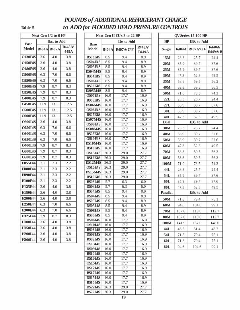
POUNDS of ADDITIONAL REFRIGERANT CHARGEto ADD for FLOODED HEAD PRESSURE CONTROLS
19
Table 5
Next-Gen 1/2 to 6 HP
Base Model
Lbs. to Add
R404A R407A R448A/449A
O130E4S 3.6 4.0 3.8O150E4S 3.6 4.0 3.8O180E4S 3.6 4.0 3.8O200E4S 6.3 7.0 6.6O250E4S 6.3 7.0 6.6O300E4S 7.9 8.7 8.3O350E4S 7.9 8.7 8.3O400E4S 7.9 8.7 8.3O450E4S 11.9 13.1 12.5O500E4S 11.9 13.1 12.5O600E4S 11.9 13.1 12.5O200L4S 3.6 4.0 3.8O250L4S 6.3 7.0 6.6O300L4S 6.3 7.0 6.6O350L4S 6.3 7.0 6.6O400L4S 7.9 8.7 8.3O500L4S 7.9 8.7 8.3O600L4S 7.9 8.7 8.3H055E44 2.1 2.3 2.2H080E44 2.1 2.3 2.2H090E44 2.1 2.3 2.2H100E44 2.1 2.3 2.2H125E44 3.6 4.0 3.8H150E44 3.6 4.0 3.8H200E44 3.6 4.0 3.8H250E44 6.3 7.0 6.6H300E44 6.3 7.0 6.6H325E44 7.9 8.7 8.3H100L44 3.6 4.0 3.8H150L44 3.6 4.0 3.8H200L44 3.6 4.0 3.8H300L44 3.6 4.0 3.8
Next-Gen II CU’s 3 to 22 HP
Base Model
Lbs to Add
R404A R407A/C/F R448A/R449A
BS03E4S 8.5 9.4 8.9OS04E4S 8.5 9.4 8.9OS05E4S 8.5 9.4 8.9DS04M4S 8.5 9.4 8.9BS04E4S 8.5 9.4 8.9OS06E4S 8.5 9.4 8.9BS05E4S 8.5 9.4 8.9DS05M4S 8.5 9.4 8.9OS07E4S 16.0 17.7 16.9BS06E4S 16.0 17.7 16.9DS06M4S 16.0 17.7 16.9OS08E4S 16.0 17.7 16.9BS07E4S 16.0 17.7 16.9DS07M4S 16.0 17.7 16.9OS09E4S 16.0 17.7 16.9DS08M4S 16.0 17.7 16.9BS08E4S 16.0 17.7 16.9OS10E4S 16.0 17.7 16.9DS10M4S 16.0 17.7 16.9BS10E4S 16.0 17.7 16.9OS13E4S 26.3 29.0 27.7BS12E4S 26.3 29.0 27.7DS12M4S 26.3 29.0 27.7OS15E4S 26.3 29.0 27.7DS15M4S 26.3 29.0 27.7BS15E4S 26.3 29.0 27.7BS03L4S 5.7 6.3 6.0DS03L4S 5.7 6.3 6.0BS04L4S 8.5 9.4 8.9DS04L4S 8.5 9.4 8.9BS05L4S 8.5 9.4 8.9DS05L4S 8.5 9.4 8.9OS08L4S 8.5 9.4 8.9BS06L4S 8.5 9.4 8.9DS06L4S 16.0 17.7 16.9OS10L4S 16.0 17.7 16.9BS08L4S 16.0 17.7 16.9DS08L4S 16.0 17.7 16.9BS09L4S 16.0 17.7 16.9OS13L4S 16.0 17.7 16.9DS09L4S 16.0 17.7 16.9BS10L4S 16.0 17.7 16.9DS10L4S 16.0 17.7 16.9OS15L4S 16.0 17.7 16.9DS12L4S 16.0 17.7 16.9BS12L4S 16.0 17.7 16.9DS15L4S 16.0 17.7 16.9BS15L4S 16.0 17.7 16.9DS22L4S 26.3 29.0 27.7BS22L4S 26.3 29.0 27.7
QV-Series 15-100 HPHP LBS. to Add
Single R404A R407A/C/F R448A/R449A/B
15M 23.3 25.7 24.420M 35.9 39.7 37.625M 35.9 39.7 37.630M 47.3 52.3 49.535M 53.8 59.5 56.340M 53.8 59.5 56.350M 71.0 78.5 74.322L 23.3 25.7 24.427L 35.9 39.7 37.630L 35.9 39.7 37.640L 47.3 52.3 49.5Dual LBS. to Add30M 23.3 25.7 24.440M 35.9 39.7 37.650M 35.9 39.7 37.660M 47.3 52.3 49.570M 53.8 59.5 56.380M 53.8 59.5 56.3100M 71.0 78.5 74.344L 23.3 25.7 24.454L 35.9 39.7 37.660L 35.9 39.7 37.680L 47.3 52.3 49.5
Parallel LBS. to Add
50M 71.8 79.4 75.160M 94.6 104.6 99.170M 107.6 119.0 112.780M 107.6 119.0 112.7100M 141.9 157.0 148.644L 46.5 51.4 48.754L 71.8 79.4 75.160L 71.8 79.4 75.180L 94.6 104.6 99.1

QV-SERIES MINIMUM CHARGE MONITOR for NON-FLOODEDCONDENSER MODELS
Use the status of each sight glass and the table to determine proper charge.
20
21
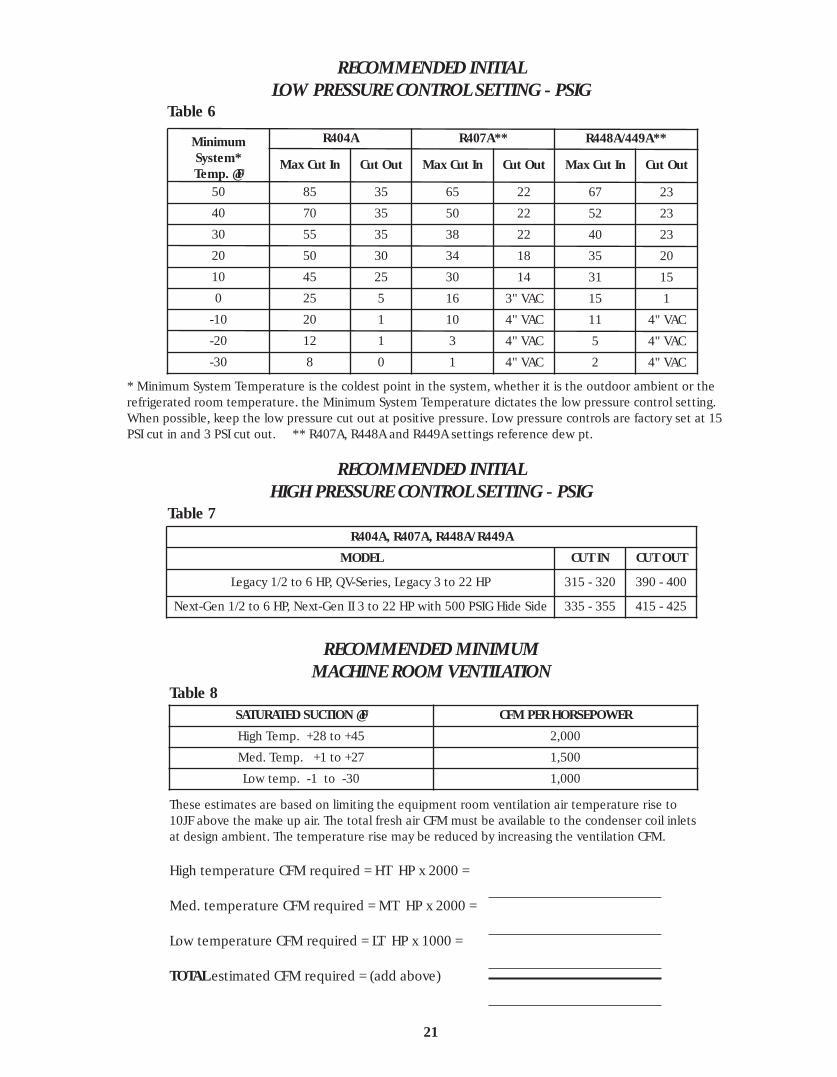
RECOMMENDED INITIALLOW PRESSURE CONTROL SETTING - PSIG
RECOMMENDED INITIALHIGH PRESSURE CONTROL SETTING - PSIG
RECOMMENDED MINIMUMMACHINE ROOM VENTILATION
MinimumSystem*Temp. @ F
R404A R407A** R448A/449A**
Max Cut In Cut Out Max Cut In Cut Out Max Cut In Cut Out
50 85 35 65 22 67 2340 70 35 50 22 52 2330 55 35 38 22 40 2320 50 30 34 18 35 2010 45 25 30 14 31 150 25 5 16 3" VAC 15 1
-10 20 1 10 4" VAC 11 4" VAC-20 12 1 3 4" VAC 5 4" VAC-30 8 0 1 4" VAC 2 4" VAC
* Minimum System Temperature is the coldest point in the system, whether it is the outdoor ambient or therefrigerated room temperature. the Minimum System Temperature dictates the low pressure control setting.When possible, keep the low pressure cut out at positive pressure. Low pressure controls are factory set at 15PSI cut in and 3 PSI cut out. ** R407A, R448A and R449A settings reference dew pt.
Table 6
R404A, R407A, R448A/R449A
MODEL CUT IN CUT OUT
Legacy 1/2 to 6 HP, QV-Series, Legacy 3 to 22 HP 315 - 320 390 - 400
Next-Gen 1/2 to 6 HP, Next-Gen II 3 to 22 HP with 500 PSIG Hide Side 335 - 355 415 - 425
Table 7
SATURATED SUCTION @ F CFM PER HORSEPOWER
High Temp. +28 to +45 2,000
Med. Temp. +1 to +27 1,500
Low temp. -1 to -30 1,000
These estimates are based on limiting the equipment room ventilation air temperature rise to10J F above the make up air. The total fresh air CFM must be available to the condenser coil inletsat design ambient. The temperature rise may be reduced by increasing the ventilation CFM.
High temperature CFM required = HT HP x 2000 =
Med. temperature CFM required = MT HP x 2000 =
Low temperature CFM required = LT HP x 1000 =
TOTAL estimated CFM required = (add above)
Table 8

22
DEFROST
AIR DEFROST - An air defrost system, sometimes called off-cycle, is wired so that the evaporator fans run continuously,unless manually de-energized. Whenever the compressor stops,the room air (minimum = 34J F) warms the coils to roomtemperature melting the frost. It is essential that the frostcompletely melts and drains each time the compressor cyclesoff. If it does not, a partial defrost results, and the residualwater and slush will re-freeze into ice during the next run cycle.Ice removal will require a manual defrost.
Adequate of cycle time is a function of system capacity. If thesystem is too small for the room, ice build-up will usually result.Use of an air defrost timer is sometimes successful onundersized systems to avoid coil icing. A temporary rise in roomtemperature will occur during the defrost cycle.
Optional defrost timers are suitable for Time Initiated, andeither Time or Temperature terminated air defrost. Timetermination is done by setting the fail-safe dial of the timer tothe desired defrost duration. This keeps the compressor offduring that duration. Temperature termination requires themounting of a close-on-rise termination thermostat whoseremote sensing bulb can be affixed to the coil at the point ofheaviest frosting. The best setting for the terminationtemperature is usually the design room temperature.
ELECTRIC DEFROST - The recommended electric defrost circuitryis typical wiring designed for the Paragon 8145-20 and GrasslinDTSX defrost timers, with the addition of Lock-out Relay R1. Thisrelay prevents the simultaneous operation of the compressorand the defrost heaters, and thus avoids the need for oversizedwiring and service.
Relay R1 contact (4-5) is normally closed (relay de-energized),and is wired in series with the defrost heaters and terminal 3(heater power) in the timer. Whenever R1 is energized, the relaycontact opens, breaking the heater power circuit. R1 holdingcoil is in parallel with the compressor motor on single phase, orthe compressor contactor holding coil (M1) on three phase, andis therefore energized any time the compressor starts. Whenthe timer switches the system into defrost, the heaters will notenergize until the compressor completes pumpdown and stops,even through the timer has applied power to terminal 3. If thecompressor starts up for additional pumpdown during defrost,R1 energizes, breaking power to the heaters until thecompressor stops again.
TIMER SETTING - Timers should be set to the correct time.Determine the number of defrost per day and the best time ofday to occur. Insert defrost pins accordingly. Set the fail-safetime to terminate the defrost a few minutes beyond theestimated temperature termination time. Air defrost fail-safe(termination time) is usually 30 to 50 minutes. The colder theroom, the longer the fail-safe time required. Electric defrostsystems normally have a 25 to 35 minute fail-safe time. Hot gasdefrost systems usually have a 15 minute fail-safe.
SUCCESSFUL DEFROSTING - Numerous factors should beconsidered when selecting and starting up low temperaturerefrigeration systems. For storage freezers holding packagedproduct, two defrost per day is normal. If the freezer has heavyusage with lots of door openings then three or four defrost perday may be required. For blast chilling and freezing or freezingof products with high moisture content, six or more defrost perday may be necessary. Do not have more defrosts than arenecessary. Unnecessary extra defrosts add heat to therefrigerated space that must be removed. Excessive defrostperiods may also cause steaming and lead to undesirable iceformation on the unit cooler, ceiling, and product.
Another factor to consider when determining the frequency ofdefrost is oil return. Oil will tend to settle out in the evaporatoror suction line on low temperature systems. This oil shouldreturn to the compressor shortly after a defrost. Watch thecompressor oil level. If it becomes low, a defrost may beneeded for oil return. In critical situations an oil separator maybe required. Two to four defrost per day are usually sufficientto maintain proper oil level in the compressor. Synthetic (POE)lubricants are considered more miscible with refrigerants thanmineral oil and do not separate out as rapidly. Someinstallations may require only one defrost per day.
Evaporators with a medium frost load will defrost best. If thefrost load is very light, the moisture cannot form water dropsand run off the fins. Instead, it will vaporize off as steam andcan create ice on colder surfaces like the ceiling, fan blades, fanguards, and evaporator housing. With medium frost loads, thefrost will melt off as water and drain away. Too heavy a frostload will restrict air flow and cause uneven temperature in thefreezer. Defrost with a medium frost load to maintain stableroom temperature, optimum evaporator performance, andhave a complete clearing of all frost.
Once ice forms in an evaporator coil it keeps building more iceand eventually will lead to equipment failure if not manuallydefrosted. Some symptoms of ice forming in the coil are: (1)Loss of air circulation and air throw, (2) Loss of roomtemperature, (3) No off-cycle time, (4) Floodback, and (5)Water spitting out of the fans or coil on air defrost systems.Long term ice formation will crush the refrigerant tubes in thecoil causing leaks and major equipment problems. If iceformation is suspected, carefully check the interior rows of thecoil with a good light. Ice formation usually starts at the bottomof the coil in the middle rows and can be difficult to detect. Anyice formation, however small, requires a manually assisteddefrost. Clear 100% of the ice before placing a unit back intooperation.

23
Always allow space for good air throw, air circulation, airreturn, cleaning and servicing of the evaporator unit. Alwaysleave air circulation space between the products and walls ofthe cooler. Leave space between the boxes or cartons ofproduct for the fastest temperature reduction or freezing. Thelarger the mass of product, the longer it takes to remove heatfrom the center of that mass. Divide the mass with aircirculation space so the circulating cold air can carry the heataway from the product faster. Baffles may be required to directair to specific areas of a room. How the product is stacked willinfluence pulldown time and stable product temperature.Direct the air to flow over and through the product. Refer tothe evaporator location recommendations on page 4 to 5. It isa good practice to avoid stacking product closer than 12 inchesto the evaporator drain pan. The room size, layout, aisle ways,heigh, door location, product stacking, and other factorsinfluence the location of the evaporator. Locate evaporators sothat the air pattern covers the entire room. Avoid placingevaporators above or close to doors. Direct the air stream
toward the door or down an aisle when possible. Use stripcurtains on doors if they are open frequently or for extendedperiods. Minimize the entry of warm, humid, air into the room.
There are always exceptions to the guidelines for general usestorage cooler or freezers. Special exceptions could be theproduct, air velocity, temperature, humidity, process, people,or machinery involved. Tomatoes, bananas, flowers, meatcutting and processing, and many other products have specialrequirements. Work or process rooms with people involvedalso have specifications requiring special attention. Facilitieswith USDA or other inspections can have special regulationsand we suggest contacting the local inspector when selectingand locating equipment. Blast chill or blast freeze rooms mayrequire special equipment or parts. We have years ofexperience and are always ready to assist you with specialapplications or projects.
PRODUCT LOADING and AIR CIRCULATION
Drawing 9 TYPICAL EVAPORATOR LOCATION IN A FREEZER
Normally 6J to 12J is acceptable on most refrigeration systems.Preferably 6J to 8J on low temperature systems and 8J to 10Jon medium temperature systems. Obtain evaporator superheatby measuring the suction line temperature at the expansionvalve bulb. Obtain pressure at a Schrader fitting in theevaporator suction connection area, near the expansion valvebulb, and convert to dew point temperature with a pressure-
temperature chart. Subtract the converted temperature fromthe measured temperature and the difference is superheat atthe evaporator. Obtain the desired superheat by adjusting theexpansion valve. Evaporator superheat greater than 14J F cansubstantially reduce the evaporator and system capacity, whilesuperheat less than 4J F has the potential for floodback.
EVAPORATOR SUPERHEAT

24
To improve compressor life expectancy 25J to 40J ofcompressor superheat is preferred. Copeland recommends aMINIMUM of 20J F superheat at the compressor. Compressorsuperheat is sometimes called suction superheat. Obtaincompressor super-heat by measuring the suction linetemperature about 6 to 12 inches from the compressor servicevalve. Obtain pressure at the suction service valve and convertto temperature with a pressure-temperature chart. Subtractthe converted temperature from the measured temperatureand the difference is superheat at the compressor. Compressorsuperheat is a critical valve and should override evaporatorsuperheat. Too low a compressor superheat can permit liquidreturn to the compressor causing damage or failure. Too high acompressor superheat can cause high discharge temperature,resulting in lubricant breakdown, compressor overheating and
can lead to compressor damage or failure. System capacitydecreases as compressor superheat increases so superheatshould be as low as practical, but with 20J F MINIMUM at alltimes. Compressor superheat can be charged by adjusting theexpansion valve, adding a suction-liquid line heat exchanger, orby insulating just the suction line. Remember that increasingthe superheat at the evaporator will decrease the evaporatorcapacity. For that reason, suction-liquid line heat exchanger areoften used on systems with short line runs. Each system mustbe thoughtfully planned and adjusted to obtain optimumperformance.
Maximum superheats must be observed with extended rangemodels.
COMPRESSOR SUPERHEAT
Although compressors may be capacity rated with 65J F returngas, most low temperature systems should not be operated atthat condition. A 65J F return gas is usually acceptable onmedium temperature systems. We recommend a 20J F to 40J Fmaximum return gas temperature on low temperaturesystems. Higher return gas temperatures on low temperaturesystems may cause compressor overheating and shorten
compressor life. Always maintain a minimum 20J F superheat atthe compressor.
If necessary, insulate the suction line on low temperaturesystems to improve the return gas temperature and superheatat the compressor. Always observe maximum return gastemperatures noted in the product literature.
RETURN GAS TEMPERATURE
The discharge line temperature should be measured about 6inches down line from the compressor discharge service valve.Discharge line temperature has a direct relationship to internaltemperatures in the compressor. A discharge line temperatureof 220J F or lower is desirable and will improve compressor lifeexpectancy. Maintaining a discharge line temperature below220J F prevent oil breakdown, prevents excess wear on internalparts, and is assurance that the compressor is not overheating.Copeland recommends a MAXIMUM discharge linetemperature of 225J F. “Lower is better”.
There is a relationship between discharge line temperatureand return gas temperature. Lowering the return gastemperature by insulating the suction line will usually lowerthe discharge line temperature about the same degree.
Make sure low temperature compressor have a direct air blastover the compressor body. This air blast is essential tomaintain proper cooling of low temperature compressors.Check head cooling fans for operation.
An operational check and adjustment is recommended afterthe room has pulled down to operating temperature and theoutdoor ambient is above 70J F. To simulate design conditions,the condenser face can be partially blocked (Do not blockcondenser air blast cooling compressor body) to raise the headpressure. Carefully adjust each system for optimumperformance and trouble free long life.
DISCHARGE LINE TEMPERATURE

25
The low temperature scroll compressor is provided with aninjection port suitable for connection to a source of liquidrefrigerant. Internally, this port is connected to an inner pocket
of the scroll mechanism. Since this pocket is separated from thesuction inlet, no loss of capacity or mass flow results frominjecting at this point.
SCROLL COMPRESSOR OPERATION
LIQUID INJECTION
The purpose of the DTC valve is to eliminate the need for acapillary tube on the 2 through 9 horsepower "ZF" scroll modelfamily. The DTC valve is approved for all refrigerants in this
product range. A DTC valve must be used for ZF**K4Eapplications with R-407C, R-407A, R-448A and R-449A.
DISCHARGE TEMPERATURE CONTROL VALVE
Refrigeration scroll compressors (up to 9 HP size) have internalpressure relief valves which open at a discharge to suction
differential pressure of 375 to 450 psi. This action will trip themotor protector and remove the motor from the line.
IPR VALVE
Single phase scrolls are designed with PSC type motors andtherefore will start without the need of start assist devices inmost applications. However, if low voltage conditions exist at
start-up, protector trips can result. Therefore start assistdevices (start capacitors & relays) are available to maximizestarting characteristics under abnormal conditions.
STARTING CHARACTERISTICS
Brief power interruptions (less than 1/2 second) may result inpowered reverse rotation of single phase Copeland Scrollcompressors. High pressure discharge gas expands backwardsthrough the scrolls at power interruption, causing the scroll toorbit in the reverse direction. If power is re-applied while this
reversal is occurring, the compressor may continue to runnoisily in the reverse direction for several minutes until thecompressor’s internal protector trips. This has no negativeimpact on durability. When the protector resets the compressorwill start and run normally.
BRIEF POWER INTERRUPTIONS
Scroll compressors are directional dependent; i.e. they willcompress in one rotational direction only. Three phase scrollswill rotate in either direction depending on power phasing.Since there is a 50/50 chance of connected power being“backwards”, contractors should be warned of this.Appropriate instructions or notices should be provided by the
OEM. Verification of proper rotation can be made byobserving that the suction pressure drops and the dischargepressure rises when the compressor is energized. No timedelay is required on three phase models to prevent reverserotation due to brief power interruptions.
THREE PHASE SCROLL COMPRESSORS – DIRECTIONAL DEPENDENCE

26
TROUBLE-SHOOTING REFRIGERATION SYSTEMSPROBLEM POSSIBLE CAUSES POSSIBLE CORRECTIVE ACTION
1. Fused disconnect switch or circuit 1. Close switch and / or breaker.
breaker open.
2. Blown fuse or tripped breaker. 2. Check for reason and repair. Replace fuse after
correcting problem.
3. Low line voltage. 3. Check line voltage; if more than 10% from
compressor marking, correcting is necessary.
4. Compressor motor protector open. 4. Motor protector automatically resets. Allow time
for compressor to cool down so protector will reset.
COMPRESSOR Restart and check for reason overheat occurred.
WILL 5. Defective compressor contactor. 5. Replace contactor.
NOT 6. Open room thermostat . 6. Check room temperature. If temperature is proper,
RUN wait for thermostat to close.
7. Open low pressure control. 7. Check low pressure control settings. See page 20
for initial settings and adjust as required.
8. Open defrost timer. 8. Check defrost timer for proper operation. Replace
if defective.
9. Open oil failure switch. 9. Check for causes of low pressure and reset switch.
10. Liquid line solenoid will not open. 10. Check holding coil; replace if defective.
11. Compressor motor defective. 11. Check motor for open circuit, short-circuit,
grounded windings or burn-out.
12. Loose wiring. 12. Check all wire terminals and tighten as necessary.
1. Flooding of liquid refrigerant into 1. Check expansion valve superheat setting.
COMPRESSOR crankcase
NOISY 2. Compressor hold-down nuts too 2. Loosen compressor hold-down nuts until
OR tight. compressor floats freely on mounting springs.
VIBRATING 3. Scroll compressor rotation sensitive. 3. Rewire for reverse rotation.
4. Worn or damaged compressor. 4. Replace the compressor.
1. Too much refrigerant. 1. Remove excess refrigerant.
HIGH 2. Non-condensibles in system. 2. Remove non-condensibles from system.
HEAD 3. Dirty condenser coil. 3. Clean condenser coil.
PRESSURE 4. Condenser fan not running. 4. Check electrical circuit and fuse. Check fan cycling
controls.
5. Discharge valve partially closed. 5. Open valve.
1. Improper suction pressure regulator 1. Check electrical circuit and fuse. Check fan cycling
setting.
HIGH 2. Thermostatic expansion valve 2. Check bulb location and clamping.
SUCTION pressure limit feature incorrect Adjust superheat.
PRESSURE or inoperative. Overfeeding. Replace expansion valve power head
3. Damaged valves in compressor. 3. Replace valve plate or compressor.
4. Worn piston rings and/or cylinder. 4. Replace compressor.
5. Room load too large. 5. Reduce the load or add more equipment.
27
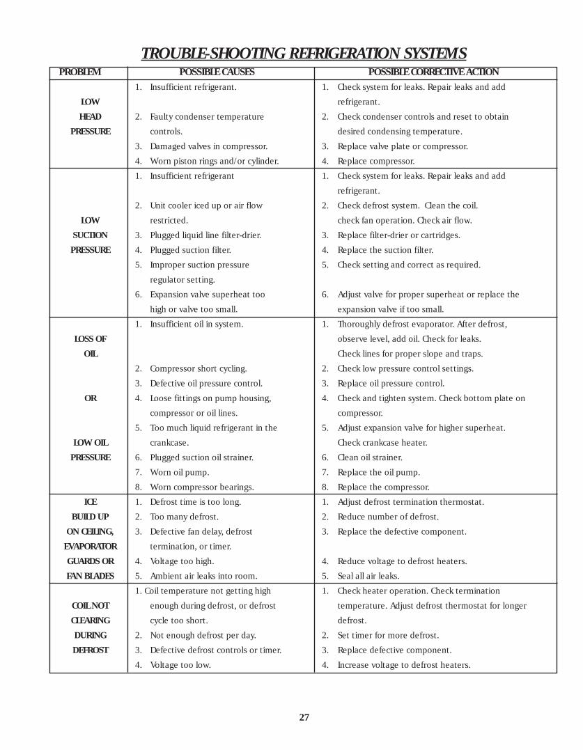
TROUBLE-SHOOTING REFRIGERATION SYSTEMSPROBLEM POSSIBLE CAUSES POSSIBLE CORRECTIVE ACTION
1. Insufficient refrigerant. 1. Check system for leaks. Repair leaks and add
LOW refrigerant.
HEAD 2. Faulty condenser temperature 2. Check condenser controls and reset to obtain
PRESSURE controls. desired condensing temperature.
3. Damaged valves in compressor. 3. Replace valve plate or compressor.
4. Worn piston rings and/or cylinder. 4. Replace compressor.
1. Insufficient refrigerant 1. Check system for leaks. Repair leaks and add
refrigerant.
2. Unit cooler iced up or air flow 2. Check defrost system. Clean the coil.
LOW restricted. check fan operation. Check air flow.
SUCTION 3. Plugged liquid line filter-drier. 3. Replace filter-drier or cartridges.
PRESSURE 4. Plugged suction filter. 4. Replace the suction filter.
5. Improper suction pressure 5. Check setting and correct as required.
regulator setting.
6. Expansion valve superheat too 6. Adjust valve for proper superheat or replace the
high or valve too small. expansion valve if too small.
1. Insufficient oil in system. 1. Thoroughly defrost evaporator. After defrost,
LOSS OF observe level, add oil. Check for leaks.
OIL Check lines for proper slope and traps.
2. Compressor short cycling. 2. Check low pressure control settings.
3. Defective oil pressure control. 3. Replace oil pressure control.
OR 4. Loose fittings on pump housing, 4. Check and tighten system. Check bottom plate on
compressor or oil lines. compressor.
5. Too much liquid refrigerant in the 5. Adjust expansion valve for higher superheat.
LOW OIL crankcase. Check crankcase heater.
PRESSURE 6. Plugged suction oil strainer. 6. Clean oil strainer.
7. Worn oil pump. 7. Replace the oil pump.
8. Worn compressor bearings. 8. Replace the compressor.
ICE 1. Defrost time is too long. 1. Adjust defrost termination thermostat.
BUILD UP 2. Too many defrost. 2. Reduce number of defrost.
ON CEILING, 3. Defective fan delay, defrost 3. Replace the defective component.
EVAPORATOR termination, or timer.
GUARDS OR 4. Voltage too high. 4. Reduce voltage to defrost heaters.
FAN BLADES 5. Ambient air leaks into room. 5. Seal all air leaks.
1. Coil temperature not getting high 1. Check heater operation. Check termination
COIL NOT enough during defrost, or defrost temperature. Adjust defrost thermostat for longer
CLEARING cycle too short. defrost.
DURING 2. Not enough defrost per day. 2. Set timer for more defrost.
DEFROST 3. Defective defrost controls or timer. 3. Replace defective component.
4. Voltage too low. 4. Increase voltage to defrost heaters.

28
WATER COOLED CONDENSER MAINTENANCESHELL & TUBE CONDENSER
General : The unit should be level with no horizontalpitch. Connect water lines according to the localplumbing codes.
Fittings : Fittings should be in line so that they are notunder tension or forced in anyway. Vibration isolationshould be used. If the fittings are out of line or understrain, threads on the fittings may be damaged. Brazedconnections must also be carefully aligned beforebrazing.
Testing : Test for water circuit leaks. Water flow ratesbelow eight feet per second are recommended. Highervelocity through the tubes results in greater risk ofimpingement corrosion and tube failure.
WATER CONNECTIONS FOR CITY
WATER CONNECTIONS FOR TOWER
Draining : Theoretically it is easy to drain a condenser; inpractice it is complex. As much as 20% of the water inthe condenser can be retained if the service techniciansimply opens the vent and drain fittings on thecondenser. To fully drain all water from the condensertubes, it is necessary to take off the back plate and tiltthe condenser a minimum of 5 degrees.
Chemical Cleaning : Use only preparations from anestablished, reliable source. follow directions exactly,particularly regarding amounts to use and flushing orneutralizing procedure after cleaning.
Mechanical Cleaning : Drain water from condenser.Remove the nuts, water plates and gaskets from bothends of the condenser. If space is limited, the tubes canbe cleaned with only one open end, however it is difficult to flush out closed ended passages.
Cleaning Procedure : Gaskets need only to be rinsed inrunning water. A rag or soft brush is all that is needed toremove rust any foreign matter. Clear water or a softbrush such as a paint brush should be used to clean theinside of the water end plates.
DO NOT SCRATCH OR DAMAGE THE EPOXY COATING ON THEINSIDE SURFACE OF THE END PLATES. NEVER USE A WIREBRUSH OR STRONG CAUSTICS ON THESE SURFACES.
Condenser tubes should be flushed clear with air orwater. If a rough coating remains inside the tubes,further cleaning is desirable. Nylon, brass or Copperbrushes are recommended. Never use any tool which willscratch or otherwise damage the tube surface. Stopwhen a few places begin to show a Copper color.
After cleaning, wipe all foreign matter from the tubesheets and stubs. To reassemble, replace clean gaskets,water end plates and nuts. Test for leaks. If no leaks arefound, the condenser should be isolated from theremaining system and evacuated. After assuring thatthere are no refrigerant circuit leaks the condenser canbe replaced into the system.

29
Customer __________________________________________ Job Name ______________________________________________
City / State __________________________________ System No. _____________________________ Date ________________
Condensing Unit Model No. __________________________________________ Serial No. ________________________________
Evaporator Model No. ____________________________________ Qty. ______ Serial No. _______________________________
Room No. or Name ____________________________ Design Temp. _______________J F Size(Ft.)______L x ______W x ______H
Suction Line ___________OD Liquid Line ____________OD Equivalent Length ____________Ft. Liquid Lift ____________Ft.
Leak Test at _______________________ PSIG, For______________________ Hours System is Leak Free ____________________
Evacuated _________Times to ________ Microns + Final Vacuum to ___________ Microns, for _________ Hours Total Hrs ______
Sight Glass Dry _________ Pressure Controls Set ___________ Thermostat Set ___________ Outdoor Ambient _____________J F
Design Voltage _____________________ Test Volts _____________________ Control Circuit Volts ______________________
Disconnect Fuse Size ___________ Amps Control Circuit Fuse _______ Amps Estimated Refrigerant Charge _____________ Lbs.
Refrigerant R-_____________ Charge _______+________+________ = ________ Total Lbs. Sight Glass Clear ______________
Compressor Oil Level ______________ Glass Evap. Fans Running ________________ Room Temp at Start-up _____________J F
Room Temp. at 1 Hr. ____________J F Compressor Oil Level ______________ Glass Defrost Timer Set ___________________
Room Temp. at 2 Hr. ____________J F Compressor Oil Level ______________ Glass Sight Glass Clear ___________________
Room Temp. at 4 Hr. ____________J F Compressor Oil Level ______________ Glass Outdoor Ambient ___________________
Electrical Specplate Test Amps
Component Amps L1 L2 L3
Compressor _______________________ ___________ __________ ____________
Condenser _______________________ ___________ __________ ____________
Evaporator _______________________ ___________ __________ ____________
Defrost Heaters _______________________ ___________ __________ ____________
Evaporator Suction Temp ____________J F Evaporator Suction Pressure ____________ PSIG
Convert PSIG to _____________J F Evaporator Superheat _____________J F
Compressor Suction Temp _______________J F Compressor Suction Pressure ______________PSIG
Convert PSIG to ______________J F Compressor Superheat _______________J F Sight Glass Clear _______________
Compressor Discharge Pressure __________________PSIG Compressor Discharge Line Temp ____________________J F
Liquid Temp. Leaving Condensing Unit _______________J F Liquid Temp. Entering Expansion Valve ________________J F
Evaporator Drain Line Trapped _____________, Heated _____________, Sloped ____________, Will not freeze up ______________
Type of Defrost: ________ Air ________Electric ________Hot Gas Defrost Time ________Min. Is CoilClean? ____________
Temperature Termination _____________ Fan Delay ____________ Is Defrost Satisfactory? ______________
Compressor Oil Level ____________Glass Timer Set ____________Defrost per Day with ____________Minute Fail Safe
Room Thermostat Set at _____________J F Room Temp. Holding at ________________J F
FINAL Evaporator Superheat _____________J F Sight Glass Clear __________ Pumpdown OK ___________
CONDITION Compressor Superheat ______________J F Compressor Oil Level ____________Glass
Discharge Line Temperature ____________J F Suction Pressure ______________PSIG
Start-Up By:________________________________ Company: _____________________________ Phone: _________________
SYSTEM START -UP CHECK LIST

30
Customer ___________________________________________ Job Name _____________________________________________
City / State ____________________________________ System No. ___________________________ Date ________________
Condensing Unit Model No. ______________________________________________ Serial No. ____________________________
Evaporator Model No. _____________________________________ Qty. _____ Serial No. _______________________________
Room No. or Name ________________________________ Design Temp. ____________J F Actual Room Temp. ____________J F
Date System was Installed ___________________ Product Stored _______________________ Total Pounds _________________
Routine / Scheduled Preventive Maintenance Service Call Outdoor Ambient ________J F
Service Requested ____________________________________________________________________________________________
____________________________________________________________________________________________________________
Service Performed ____________________________________________________________________________________________
____________________________________________________________________________________________________________
____________________________________________________________________________________________________________
Design Voltage ______________________ Actual Voltage ______________________ Refrigerant R- _____________________
Electrical Specplate Test Amps
Component Amps L1 L2 L3
Compressor _______________________ ___________ __________ ____________
Condenser _______________________ ___________ __________ ____________
Evaporator _______________________ ___________ __________ ____________
Defrost Heaters _______________________ ___________ __________ ____________
Evaporator Suction Temp _________________J F Evaporator Suction Pressure _________________ PSIG
Convert PSIG to __________________J F Evaporator Superheat __________________J F
Compressor Suction Temp ____________________J F Compressor Suction Pressure ___________________PSIG
Convert PSIG to _____________J F Compressor Superheat ____________J F Sight Glass Clear _____________
Compressor Discharge Pressure _______________PSIG Compressor Discharge Line Temp _________________J F
Compressor Oil Level _____________Glass Sight Glass Clear ____________ Sight Glass Dry ______________
Cond. Coil Clean _______ All Cond. Fans Operate ________ Liquid Temp. Leaving Cond. Unit ___________J F
Room Thermostat Set at _________________J F Room Temperature Holding at __________________J F
Evaporator Coil Clean _____________ Drain Pan Clean ___________ Fan Blades / Guards Clean _____________
All Evap. Fans Operate _____________ Room Air Circulation OK _____________ Defrosting OK ____________
System Pumpdown OK _____________ Cooler and Equipment in Safe Condition ___________________________
System Notes: __________________________________
______________________________________________
______________________________________________
______________________________________________
______________________________________________
______________________________________________
REFRIGERATION SYSTEM SERVICE RECORD
Serviced by __________________________________

SYSTEM MAINTENANCERemove all leaves, grass, paper, lint, fluff, soil, feathers, cottonwood hair, or other materials from the condenser coilwith a brush, blower, or vacuum. Grease and dirt removal may require washing with a coil cleaning detergent. Alwaysrinse thoroughly with clean water after using a chemical cleaner. Do not use cleaners containing ammonia. The coilmust be kept clean at all times. Be sure the condenser fans are operating and the air flow is not restricted. Keep thecondensing unit area clean.
There is additional oil installed in the compressor to allow for a limited amount to circulate throughout the system withthe refrigerant. The oil is clear and can be difficult to see if above the oil level glass. The longer the compressor runs thelower the oil level may go. The oil level may approach the bottom of the glass before the system cycles off or a defrostoccurs. After an off cycle or defrost period, the oil normally returns to the compressor. Once the room is down todesign temperature the oil level range should be about 1/8 to 5/8 glass.
Excess oil dangerous to the compressor. Do not add oil just because the oil safety trips out. Thoroughly check out theloss oil or oil pressure on trouble-shooting, page 27, before adding oil. Correct any condition that prevents oil return tothe compressor. Visually check the oil pump, oil lines, and compressor bottom plate area for oil leaks.
Add only lubricant approved by the compressor manufacturer. Polyol ester, “POE”, synthetic lubricant must be used withR404A, R407A, R407C, R448A/R449A and R507 systems. Take caution not to fill above 1/2 glass. POE lubricants quicklyabsorb moisture from the atmosphere. The system must be kept sealed as much as possible to prevent moisturecontamination.
Check the system pressures and temperatures on a regular basis to be sure they are within the guidelinesrecommended on page 24. Refer to trouble-shooting on page 26 and 27 for suggestions.
Evaporators should be checked frequently and cleaned of dirt and grease accumulation. Disconnect electrical power tothe evaporator when inspecting or cleaning. The fan blades, fan guards and coil may require frequent cleaning. Do notuse ammonia or other cleaning chemicals that are corrosive to Copper or Aluminum. The drain pan should be loweredfor inspection and thoroughly cleaned to prevent buildup of foreign materials. Make sure the drain connection area isclean and clear.
Make sure all motors and fans are in good operating condition. If uneven frosting of the coil is observed, look for airleaking into the room. Eliminate all air leaks for optimum evaporator performance and energy savings. Do not leave theaccess panels off after adjustment or service. The access panels should always be in place when the evaporator isoperating. Keep cold room doors closed when possible.
TO INQUIRE OR ORDER REPLACEMENT PARTS
Email: [email protected] Telephone (800) 288-9488 or (256) 259-7400 Fax (256) 259-7478
1. Provide the complete Model Number and Serial Number of the unit.2. Provide a detailed description of the part with any model, diameter, HP, or other markings.3. State the quantity you are ordering.4. Advise special shipping methods, routes, procedures, or instructions with ship to address.5. Provide complete and accurate data to insure prompt and accurate delivery.6. Compressors and compressor parts must be obtained from your local wholesaler.
31