paraparaumu substation 220kv connection - … is beyond the scope of this report to define the ......
TRANSCRIPT

PRM 220kV ConnectionTranspower10 May 2013
Paraparaumu Substation220kV ConnectionEnvironmental Noise Modelling for SSR


AECOM PRM 220kV ConnectionParaparaumu Substation 220kV Connection
10 May 2013
Paraparaumu Substation 220kV ConnectionEnvironmental Noise Modelling for SSR
Prepared for
Transpower
Prepared byAECOM New Zealand LimitedLevel 10, 135 Victoria Street, Te Aro, Wellington 6011, PO Box 27277, Wellington 6141, New ZealandT +64 4 382 2999 F +64 4 382 2998 www.aecom.com
10 May 2013
60285897
AECOM in Australia and New Zealand is certified to the latest version of ISO9001 and ISO14001.
© AECOM New Zealand Limited (AECOM). All rights reserved.
AECOM has prepared this document for the sole use of the Client and for a specific purpose, each as expressly stated in the document. No otherparty should rely on this document without the prior written consent of AECOM. AECOM undertakes no duty, nor accepts any responsibility, to anythird party who may rely upon or use this document. This document has been prepared based on the Client’s description of its requirements andAECOM’s experience, having regard to assumptions that AECOM can reasonably be expected to make in accordance with sound professionalprinciples. AECOM may also have relied upon information provided by the Client and other third parties to prepare this document, some of whichmay not have been verified. Subject to the above conditions, this document may be transmitted, reproduced or disseminated only in its entirety.


AECOM PRM 220kV ConnectionParaparaumu Substation 220kV Connection
10 May 2013
Quality InformationDocument Paraparaumu Substation 220kV Connection
Ref 60285897
Date 10 May 2013
Prepared by Phil Blakemore
Reviewed by Claire Drewery
Revision History
Revision RevisionDate Details
Authorised
Name/Position Signature
0 3-Apr-2013 Draft for Client Review Claire DreweryPrincipal AcousticConsultant
1 17-Apr-2013 Revised Draft for ClientReview
Claire DreweryPrincipal AcousticConsultant
2 6-May-2013 Final 60% load assessment Claire DreweryPrincipal AcousticConsultant
34 8-May2013 Revised final 60% loadassessment
Claire DreweryPrincipal AcousticConsultant
4 10-May-2013 Minor revision for NORsubmission, 60% load
Joanne OliverPrincipal ElectricalEngineer/ ProjectManager


AECOM PRM 220kV ConnectionParaparaumu Substation 220kV Connection
10 May 2013
Table of Contents1.0 Introduction 12.0 Existing Site Description 13.0 Environmental Noise Criteria 24.0 Measurement Methodology 25.0 Existing Substation Results 3
5.1 Ambient Noise 35.2 Substation Noise 35.3 Transformer Loads 45.4 Discussion 4
6.0 Noise Levels 57.0 Fire Wall Data 58.0 Assessment 59.0 Mitigation 710.0 Conclusion 10
Appendix AAcoustic Nomenclature A
Appendix BMeasured Noise Spectra B
Appendix CBoundary Noise Map B


AECOM PRM 220kV ConnectionParaparaumu Substation 220kV Connection
10 May 2013
1
1.0 IntroductionAECOM was engaged by Transpower to undertake environmental noise measurements to determine theprevailing noise emissions from Transpower’s Paraparaumu Substation. An assessment of environmental noisefrom the proposed new substation which is to be located directly adjacent to the existing Substation was also partof this assessment.
Noise was measured at the existing substation by AECOM personnel between the 20th and 21st December 2012.To assist in the SSR, an acoustic noise model has been developed to determine likely incident noise levels at theadjacent residential boundaries following completion of the substation. This report documents the findings of thenoise measurements and assessment.
Definitions of the acoustic nomenclature used in this report are presented in Appendix A.
2.0 Existing Site DescriptionThe existing Paraparaumu Substation is located on Valley Road, Paraparaumu. There are a number of residentialproperties in the vicinity of the substation with the most exposed properties determined as being 125 RuapehuStreet to the west of the Substation, 137A Ruapehu Street; south and 70A Valley Road to the east.
The main noise sources associated with the substation are the substation’s two transformers. Both transformersinclude cooling fans that operate intermittently as required, to control the transformer oil temperatures.
Figure 1 presents an aerial photograph of the substation and surrounding area.
Figure 1 Site Layout (Aerial Photo Source: Google Maps)
Substation

AECOM PRM 220kV ConnectionParaparaumu Substation 220kV Connection
10 May 2013
2
3.0 Environmental Noise CriteriaAs a designated substation it is understood that the existing Valley Road Substation is exempt from the ordinarynoise rules of the District Plan. Further to this, there are no noise conditions associated with the designation forthe substation and therefore there are no set limits with which noise from the substation must comply. However,Transpower still has a duty to ensure that noise from the substation complies with the requirements of theResource Management Act 1991 (RMA), and in particular, Sections 16 and 17, which require the best practicableoption to be taken to avoid or mitigate unreasonable noise.
The level of noise that may be considered “reasonable” can be dependent on a number of factors in addition tothe absolute noise level itself, including:
- The nature or character of the noise;
- The sensitivity of the receiving environment to the effects of the noise;
- The current state of technical knowledge and the likelihood that noise mitigation measures could beimplemented successfully.
- The financial implications of implementing noise mitigation measures;
- Other effects on the environment that would occur as a result of implementing noise mitigation measures (forexample, visual effects).
It is beyond the scope of this report to define the level of noise that would be reasonable, but to provide someguidance, consideration has been given to the ordinary noise rules prescribed for the underlying residential zoneby the Kapiti Coast District Plan.
It is understood that the new substation will be required to meet the environmental noise criteria stipulated in theKapiti Coast District Plan (KCDP). The KCDP criteria are provided below.
D.1 - I Non-Residential Activities states the following:
All non-residential activities, other than transportation activities or construction, maintenance and demolition work(except in the case of temporary military training activities for which specific rules apply) shall be located,designed and carried out to ensure that the following noise levels are not exceeded at or within any residentialboundary:
7am to 10pm - 50 dBA L10
10pm to 7am - 45 dBA L10
During all night time hours (10pm to 7am) no noise event shall exceed Lmax 75dBA
The KCDP Plan goes on to state the following requirements:
Noise shall be measured in accordance with NZS 6801:1991 “Measurement of Sound” and assessed inaccordance with NZS 6802:1991 “Assessment of Environmental Sound”
4.0 Measurement MethodologyThe noise measurements were performed in accordance with NZS 6801:1991, from 23:30 on 20th December to00:30 on 21 December 2012. The weather during the measurement was clear with little wind.
A Rion NL-32 Type 1 Sound Level Meter (Serial No. 001616083) was used to perform the measurements. Thecalibration of the sound level meter was checked before and after the measurements using a portable SoundLevel Calibrator, and was found to be reading correctly on all occasions.
Noise from the substation was measured within the substation yard at a distance of 2m from the transformers andat the boundary of three different receptors to the east (70A Valley Road), south (137A Ruapehu Street) and west(125 Ruapehu Street) of the Substation. These receptors are located at the residences potentially most-affectedby noise from the substation.
An ambient noise measurement (to determine the residual noise level) was performed approximately 400m north-west of the substation along Kaitawa Crescent for a period of 10 minutes. At this location, noise from the

AECOM PRM 220kV ConnectionParaparaumu Substation 220kV Connection
10 May 2013
3
substation was not audible. The ambient noise levels were considered to be representative of the ambient noiselevels in the vicinity of the substation, excluding the noise from the substation itself.
The location of each measurement position is presented in Figure 2.
Figure 2 Measurement Locations (Aerial Photo Source: Google Maps)
5.0 Existing Substation Results
5.1 Ambient NoiseThe ambient noise levels to north-west of the substation along Kaitawa Crescent were measured to be 31.9 dBLAeq (10min). The ambient noise environment was dominated by distant traffic noise. Ambient daytime noise levelswere not undertaken but are not anticipated to differ significantly from increased activity on minor roads andvehicle movements along the State Highway, which is approximately 600m from the substation.
5.2 Substation NoiseThe measured noise levels within the substation switchyard and at the boundary of the assessment locationswere dominated by noise from the substation. Ambient noise levels during the measurement period were morethan 20dB below the prevailing background noise levels and no adjustment for residual noise influence istherefore required.
When assessed using the NZS 6802:2008 simplified test method for tonality, noise from the substation when thefans are not operating is defined as tonal for all locations. In accordance with NZS 6802:2008, a tonalityadjustment of +5 dB has been applied to the noise level measured at each receptor to derive the Rating Level.
Location 3:
70A Valley Road
Location 1:
125 Ruapehu StreetLocation 1:
137A Ruapehu Street
Location 4:
Kaitawa Crescent(Residual Noise)
Substation
AECOM PRM 220kV ConnectionParaparaumu Substation 220kV Connection
10 May 2013
4
As the substation switchyard is not a noise sensitive location there is no relevance in applying a tonalityadjustment to the measurements performed inside the switchyard.
With the transformer fans on, the level of broadband noise increases significantly, masking the tonal noise fromthe transformers. Therefore, with the fans on, no tonality adjustment is required under the simplified test methodof NZS 6802:2008.
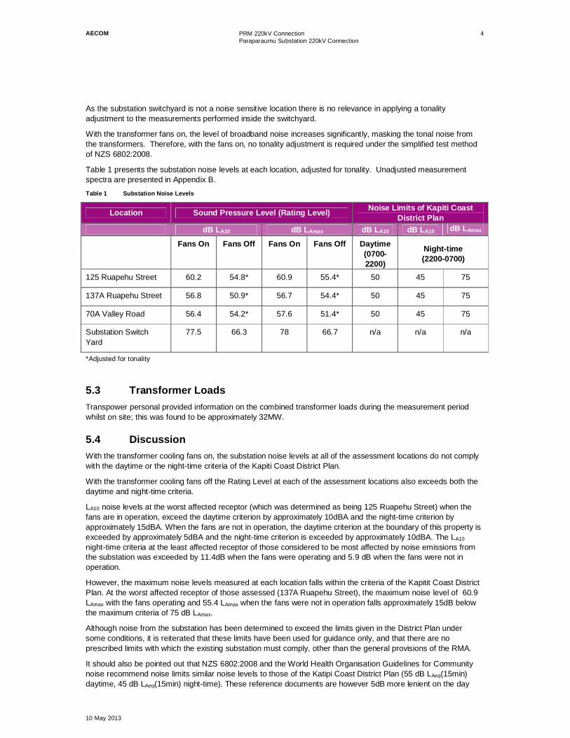
Table 1 presents the substation noise levels at each location, adjusted for tonality. Unadjusted measurementspectra are presented in Appendix B.Table 1 Substation Noise Levels
Location Sound Pressure Level (Rating Level) Noise Limits of Kapiti CoastDistrict Plan
dB LA10 dB LAmax dB LA10 dB LA10 dB LAmax
Fans On Fans Off Fans On Fans Off Daytime(0700-2200)
Night-time(2200-0700)
125 Ruapehu Street 60.2 54.8* 60.9 55.4* 50 45 75
137A Ruapehu Street 56.8 50.9* 56.7 54.4* 50 45 75
70A Valley Road 56.4 54.2* 57.6 51.4* 50 45 75
Substation SwitchYard
77.5 66.3 78 66.7 n/a n/a n/a
*Adjusted for tonality
5.3 Transformer LoadsTranspower personal provided information on the combined transformer loads during the measurement periodwhilst on site; this was found to be approximately 32MW.
5.4 DiscussionWith the transformer cooling fans on, the substation noise levels at all of the assessment locations do not complywith the daytime or the night-time criteria of the Kapiti Coast District Plan.
With the transformer cooling fans off the Rating Level at each of the assessment locations also exceeds both thedaytime and night-time criteria.
LA10 noise levels at the worst affected receptor (which was determined as being 125 Ruapehu Street) when thefans are in operation, exceed the daytime criterion by approximately 10dBA and the night-time criterion byapproximately 15dBA. When the fans are not in operation, the daytime criterion at the boundary of this property isexceeded by approximately 5dBA and the night-time criterion is exceeded by approximately 10dBA. The LA10
night-time criteria at the least affected receptor of those considered to be most affected by noise emissions fromthe substation was exceeded by 11.4dB when the fans were operating and 5.9 dB when the fans were not inoperation.
However, the maximum noise levels measured at each location falls within the criteria of the Kapitit Coast DistrictPlan. At the worst affected receptor of those assessed (137A Ruapehu Street), the maximum noise level of 60.9LAmax with the fans operating and 55.4 LAmax when the fans were not in operation falls approximately 15dB belowthe maximum criteria of 75 dB LAmax.
Although noise from the substation has been determined to exceed the limits given in the District Plan undersome conditions, it is reiterated that these limits have been used for guidance only, and that there are noprescribed limits with which the existing substation must comply, other than the general provisions of the RMA.
It should also be pointed out that NZS 6802:2008 and the World Health Organisation Guidelines for Communitynoise recommend noise limits similar noise levels to those of the Katipi Coast District Plan (55 dB LAeq(15min)daytime, 45 dB LAeq(15min) night-time). These reference documents are however 5dB more lenient on the day

AECOM PRM 220kV ConnectionParaparaumu Substation 220kV Connection
10 May 2013
5
time criteria than the KCDP. Whilst NZS 6802:2008 and the World Health Organisation Guidelines set noisecriteria is in terms of LAeq, compared to the KCDP requirements for LA10, an assessment of noise against theseguidelines would result in a similar outcome due to the consistent nature of noise from the transformers.
Given that these noise limits are exceeded in all operating conditions, it is considered that reduction of the noiselevels from the substation, and in particular the transformer fans could potentially be warranted. However, underthe new proposals, the existing transformers will no longer be in operation and mitigation to the existing substationis therefore not considered necessary.
The new substation will be designed to meet the noise levels stipulated by the KCDP (see Section 3.0) which arecurrently being exceeded by the existing transformers. This will mean a reduction in the noise levels experiencedat even the worst affected residential boundaries under normal operation of the new substation.
6.0 Noise LevelsNoise from the proposed transformers will be of a similar level to the new transformers recently installed atPakuranga substation. The Pakuranga substation transformers are of the same power rating, voltage rating andof similar design to the proposed transformers for Paraparumu. Measured noise data provided by Transpowerfrom Pakuranga substation has therefore been used in our assessment. Spectral sound power data at 60%transformer load is provided below.Table 2 Transformer Noise Levels
Sound Power Level (dB) re 10-12 W
Octave Band Centre Frequency (Hz) Total
63 125 250 500 1000 2000 4000 dBA
82 90 90 81 72 63 55 84
The noise data detailed in Table 2 for the transformer operating at 60% load does not take noise from thetransformer fans into account. Fans of the Paraparaumu transformers will not operate until the transformerreaches loads of 70%. The substation has been designed to run at 60% load under maximum normal capacityand as a result, noise from the fans does not require assessment.
Furthermore, whilst fan noise could potentially increase transformer noise emissions, operation of the fans wouldincrease broadband noise eliminating the transformers tonal component. Any increase in noise would therefore beoffset by exclusion of a tonal correction to the rating level.
7.0 Fire Wall DataThe fire walls were modelled as one-sided concrete barriers, 15m long x 8m high and located as shown indrawing 01 SSR Sk – 220 Layout.
The absorption coefficients assumed for the concrete fire walls are given below.
Table 3 Absorption Coefficients (Firewalls)
Absorption Coefficient
Material Octave Band Centre Frequency (Hz)
63 125 250 500 1000 2000 4000
Concrete 0.02 0.02 0.02 0.02 0.03 0.04 0.05
8.0 AssessmentA noise model has been constructed to determine the likely noise levels resulting from operation of the proposedtransformers at all potentially affected residential receptors within a radius of approximately 150m. Thisassessment area is shown in Figure 3 below.

AECOM PRM 220kV ConnectionParaparaumu Substation 220kV Connection
10 May 2013
6
Figure 3 Assessment Location (Aerial Photo Source: Google Maps)
The noise model has been developed to determine the likely noise levels at the residential boundaries thatsurround the Paraparaumu substation. Noise levels have been predicted at the site boundary to provide a worstcase assessment. Noise levels at the façade of the adjacent residential properties following installation of theproposed transformers are expected to be of a lower level than those provided in Table 5.
The following scenarios have been modelled:
Existing Scenario
- Hard (0% absorption) ground, two transformers, each transformer operating at 32MW as measured
T3
T4
ExistingSubstation
ProposedSubstation
Assessment Area

AECOM PRM 220kV ConnectionParaparaumu Substation 220kV Connection
10 May 2013
7
Normal Operating Conditions
• Hard (0% absorption) ground, two transformers, each at 60% load
• Hard (0% absorption) ground, two transformers, each at 60% load with mitigation
The model has been developed using the LAeq parameter because the transformer noise data is in terms of anLAeq. When the source of sound is constant in nature, there is little difference between measured LAeq and LA10
noise levels (approximately 1dB) and we therefore consider noise modelling the transformer using the LAeq
parameter to be acceptable
The transformers will not operate at 60% load for some years to come. The likely load at commissioning isexpected to be well below the 60% load used in our assessment. The analysis has therefore been carried out toindicate compliance over the full life of the transformers.
Transformers are modelled from noise levels that are based on maximum loadings throughout a 24-hour period.The transformers are assessed against the night-time criteria in order to provide a worst-case assessment. KCDPnight-time criterion is 5dB more stringent than that required during the day, designing the substation to meet thenight time criterion will result in the daytime criterion also being achieved.
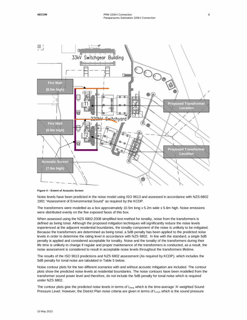
9.0 MitigationThe results obtained from the noise modelling exercise have demonstrated that the KCDP criteria will beexceeded unless acoustic mitigation methods are incorporated within the design. A 2-sided acoustic screen with aheight of 7m has been modelled, located to the south and south-east of the proposed transformers as shown inFigure 4, the acoustic screen has been used to demonstrate the most simplistic method of achieving the noisecriteria set out in the KCDP.
Other noise reducing techniques exist (e.g. quieter transformers) and the most appropriate solution orcombination of solutions will be selected at detailed design stage.
Acoustic Screens have been modelled as proprietary acoustic screens, the absorption coefficients of CookIndustries NAP AB-75 barrier have been used in the model. These absorption coefficients are provided in Table 4.Table 4 Absorption Coefficients (Acoustic Screens)
Absorption Coefficient
Material Octave Band Centre Frequency (Hz)
63 125 250 500 1000 2000 4000
NAP AB-75 0.05 0.1 0.2 0.6 0.9 0.85 0.75
In order to reduce noise levels below the KCDP criteria at residential boundaries, a proprietary acoustic screenwith a sound absorptive face will be required. The screen should be 7m high (from ground level) and will need toextend at least 1.0m to the north of the transformers (see Figure 4).
AECOM PRM 220kV ConnectionParaparaumu Substation 220kV Connection
10 May 2013
8
Figure 4 – Extent of Acoustic Screen
Noise levels have been predicted in the noise model using ISO 9613 and assessed in accordance with NZS:68021991 “Assessment of Environmental Sound” as required by the KCDP.
The transformers were modelled as a box approximately 10.5m long x 5.2m wide x 5.6m high. Noise emissionswere distributed evenly on the five exposed faces of this box.
When assessed using the NZS 6802:2008 simplified test method for tonality, noise from the transformers isdefined as being tonal. Although the proposed mitigation techniques will significantly reduce the noise levelsexperienced at the adjacent residential boundaries, the tonality component of the noise is unlikely to be mitigated.Because the transformers are determined as being tonal, a 5dB penalty has been applied to the predicted noiselevels in order to determine the rating level in accordance with NZS 6802. In line with the standard, a single 5dBpenalty is applied and considered acceptable for tonality. Noise and the tonality of the transformers during theirlife time is unlikely to change if regular and proper maintenance of the transformers is conducted, as a result, thenoise assessment is considered to result in acceptable noise levels throughout the transformers lifetime.
The results of the ISO 9613 predictions and NZS 6802 assessment (As required by KCDP), which includes the5dB penalty for tonal noise are tabulated in Table 5 below.
Noise contour plots for the two different scenarios with and without acoustic mitigation are included. The contourplots show the predicted noise levels at residential boundaries. The noise contours have been modelled from thetransformer sound power level and therefore, do not include the 5dB penalty for tonal noise which is requiredunder NZS 6802.
The contour plots give the predicted noise levels in terms of LAeq which is the time-average ‘A’-weighted SoundPressure Level. However, the District Plan noise criteria are given in terms of LA10 which is the sound pressure
Acoustic Screen
(7.0m high)
Proposed TransformerLocation
Proposed TransformerLocation
Fire Wall
(8.0m high)
Fire Wall
(8.0m high)

AECOM PRM 220kV ConnectionParaparaumu Substation 220kV Connection
10 May 2013
9
level that is exceeded for 10% of the time for which the given sound is measured. In this situation the noise fromthe transformers is relatively constant so the LAeq and LA10 noise levels will be within 1 dB of each other.
Table 5 provides the predicted noise levels (ISO 9613) and the KCDP assessment noise levels (including the+5dB penalty).
Prevailing noise levels from operation of the existing transformers have been predicted using the data obtainedfrom measurement during the noise survey. The noise model predictions have been calibrated against thesemeasured prevailing noise levels. The predicted and measured noise data was found to be within approximately1dB of one another and therefore, the model is considered to be acoustically acceptable; the predicted existingnoise levels are also included in Table 5 for comparison.Table 5 Predicted Boundary Noise Levels (Transformers at 60% Load)
Location Existing No Mitigation With MitigationdB LAeq dB LAeq dB LAeq
NZS 6802Assessment ISO 9613 NZS 6802
Assessment ISO 9613 NZS 6802Assessment
67 Valley Road 45 44 49 38 43
70 A Valley Road 53 52 57 40 45
70B Valley Road 51 44 49 33 38
72 Valley Road 47 38 43 29 34
74 Valley Road 48 39 44 29 34
76 Valley Road 48 38 43 28 33
117 Ruapehu Street 45 25 30 25 30
119 Ruapehu Street 46 28 33 26 31
121 Ruapehu Street 49 30 35 32 37
123 Ruapehu Street 54 30 35 29 34
125 Ruapehu Street 55 31 36 29 34
127 Ruapehu Street 55 33 38 29 34
129 Ruapehu Street 54 33 38 30 35
131 Ruapehu Street 52 33 38 28 33
133 Ruapehu Street 49 33 38 28 33
135 Ruapehu Street 44 35 40 28 33
137 Ruapehu Street 50 36 41 29 34
139 Ruapehu St 48 37 42 29 34
9 Valley Road 43 35 40 35 40
9A Valley Road 42 35 40 35 40
The boundary of 70A Valley Road is approximately 9m from the proposed location of the new 220kVtransformers. Worst case noise levels at the boundary have been predicted to just meet the 45dBA criteria withtransformers operating at 60% load and with the mitigation methods identified above incorporated into the design.

AECOM PRM 220kV ConnectionParaparaumu Substation 220kV Connection
10 May 2013
10
Previous versions of the acoustic report suggested that the modelled boundary noise levels could reduce by up to3dB because each transformer was expected to operate at 50% load. Since the report was issued in April thedesign has progressed. It is now anticipated that each transformer will operate at 60% load and therefore, a 3dBreduction in the modelled noise levels will not occur under future maximum loadings.
10.0 ConclusionNoise levels at the existing Paraparaumu substation on Valley Road have been measured. Measurements wereperformed with cooling fans on and off. The substation rating noise level at the boundary of the potentially most-affected residence was determined to be 54.8 dB LA10 with the transformer fans off, and 60.2 dB LA10 with fans on.
Noise from the substation with and without the fans in operation therefore exceeds both the daytime and night-time noise limits given in the Kapiti Coast District Plan. It should be noted that these limits do not strictly apply tothe existing substation as it is a designated site. As a designated site with no specific noise conditions, thesubstation need only comply with the overarching requirements of the RMA.
When considering the similar noise limits provided by NZS 6802:2008 and the World Health OrganisationGuidelines for Community Noise, the noise levels from the substation with the transformer cooling fans on wouldbe considered high. Therefore implementation of measures to reduce noise from the existing transformers couldpotentially be warranted if they were to continue in operation.
The proposed new transformers are being designed to meet the noise criteria requirements of the KCDP.Removal of the existing noisy transformers, installation of two new transformers and incorporation of acousticmitigation techniques in the substation design will under normal operating conditions, result in a reduction in noiselevels at all affected receptors.
Mitigation by new acoustic barriers and/or the specification of quiet transformers are means of mitigation beingconsidered to meet the KCDC requirements.
The inclusion of a proprietary acoustic barrier system has been modelled in the noise software. Modelling showsthat this barrier system will be effective in reducing noise from the substation to levels required by the KCDP.
Acoustic barriers have been modelled as NAP AB-75 barrier systems, an appropriate barrier system will need tobe determined during detailed design if this is the mitigation option chosen.

AECOM PRM 220kV ConnectionParaparaumu Substation 220kV Connection
10 May 2013
Appendix A
Acoustic Nomenclature

AECOM PRM 220kV ConnectionParaparaumu Substation 220kV Connection
10 May 2013
1
Appendix A Acoustic Nomenclature
dB(A)
means Decibels or ‘A’-weighted Decibels, the unit of Sound Pressure Level. ‘A’-weightingadjusts the levels of frequencies within the sound spectrum to better reflect the sensitivity of thehuman ear to different frequencies.
LAeq(T) means the ‘A’-weighted “Time-Average Sound Pressure Level” (also known as the “EquivalentContinuous Sound Pressure Level”). The Time-Average Sound Pressure Level is the constantvalue of A-Weighted Sound Pressure Level, for a given period (T), that would be equivalent insound energy to the time-varying A-Weighted Sound Pressure Level measured over the sameperiod [Unit: dB(A)]
LAFmax(T) means the maximum value of A-Weighted Sound Pressure Level measured using an ‘F’ timeweighting during the period T. [Unit: dB(A)]
LA10(T) means the value of A-weighted Sound Pressure Level which is exceeded for 10 percent of thetime during the period T. [Unit: dB(A)]
LA90(T) means the value of A-weighted Sound Pressure Level which is exceeded for 90 percent of thetime during the period T. [Unit: dB(A)]
Sound PressureLevel
is a measure of the magnitude of a sound wave (Unit: Decibels). Mathematically, it is twentytimes the logarithm to the base ten of the ratio of the root mean square sound pressure at apoint in a sound field, to the reference sound pressure; where sound pressure is defined as thealternating component of the pressure (Pa) at the point, and the reference sound pressure is2x10-5 Pa. [Unit: dB]
Rating Level is the term used by NZS 6802:2008 to describe the measured sound pressure level afteradjustments have been applied for residual noise influence and any special audiblecharacteristics. The Rating Level is the level that is assessable in relation to the noise criteria.

AECOM PRM 220kV ConnectionParaparaumu Substation 220kV Connection
10 May 2013
Appendix B
Measured Noise Spectra


AECOM PRM 220kV ConnectionParaparaumu Substation 220kV Connection
10 May 2013
1
Appendix B Measured Sound Pressure Level Spectra


AECOM PRM 220kV ConnectionParaparaumu Substation 220kV Connection
10 May 2013
2
100 125 160 200 250 315 400 500 630 800 1K 1.2K 1.6K 2 2.5 3.15 4 5Yard (Fans On) 69.0 57.9 61.7 73.0 65.2 59.9 62.7 59.7 60.7 54.6 49.3 47.0 48.0 43.3 42.7 38.3 34.2 30.0125 Raupehu Street (Fans On) 61.1 50.0 53.8 65.1 57.3 52.0 54.8 51.8 52.8 46.7 41.4 39.1 40.1 35.4 34.8 30.4 26.3 22.1Background 24.7 23.7 22.2 21.7 20.4 20 24.6 23.2 22.7 28.7 24.1 23.7 25.7 25.9 25.2 23.9 23.2 22.5Yard (Fans Off) 60.1 45.8 48.8 60.8 45.8 38.1 34.4 36.6 43.1 47.1 46.6 44.2 39.8 36.6 33.1 28.8 20.8 24.0125 Raupehu Street (Fans Off) 44.8 43.8 41.8 46.2 34.8 31.6 32.2 29.9 36.1 33.1 37 34.7 35.7 31 30.4 26 21.9 26.5
0.0
10.0
20.0
30.0
40.0
50.0
60.0
70.0
80.0A
Wei
ghte
dTi
me
Aver
aged
Soun
dPr
essu
reLe
vel(
dBLA
eq)
Paraparaumu Substation


AECOM PRM 220kV ConnectionParaparaumu Substation 220kV Connection
10 May 2013
Appendix C
Boundary Noise Map


LAeq dB
<= 28> 28> 30> 32> 34> 36> 38> 40> 42> 44> 46> 48> 50> 52> 54> 56
Signs and symbolsMain building
Transformer
Length Scale 1:329600 15 30 60 90 120
m
PRM 220kV Substation Existing Scenario


LAeq dB
<= 28> 28> 30> 32> 34> 36> 38> 40> 42> 44> 46> 48> 50> 52> 54> 56
Signs and symbolsMain building
Transformer
Length Scale 1:329600 15 30 60 90 120
m
PRM 220kV SubstationBuild (No Mitigation)


LAeq dB
<= 28> 28> 30> 32> 34> 36> 38> 40> 42> 44> 46> 48> 50> 52> 54> 56
Signs and symbolsMain building
Transformer
Length Scale 1:329600 15 30 60 90 120
m
PRM 220kV SubstationBuild (With Mitigation)