parametric and cycle tests of a 40-a-hr bipolar nickel ... · parametric and cycle tests of a...
TRANSCRIPT
NASA Technical Memorandum 88793
Parametric and Cycle Tests of a 40-A-hrBipolar Nickel-Hydrogen Battery
(NASA-TM-88793) PAfiABfTRIC AND CYCLE TESTS N86-31979OF A 40-A-Hfi BIP01AB NJCKEL-HXDfiOGEI BATTEBY(NASA) 12 p CSCL 10C
UnclasG3/1U 43495
Robert L. CataldoLewis Research CenterCleveland, Ohio
Prepared for the21st Intersociety Energy Conversion Engineering Conference (IECEC)cosponsored by the ACS, SAE, ANS, ASME, IEEE, AIAA, and AIChESan Diego, California, August 25-29, 1986
NASA
https://ntrs.nasa.gov/search.jsp?R=19860022507 2018-07-05T11:28:18+00:00Z

PARAMETRIC AND CYCLE TESTS OF A 40-A-hr BIPOLAR NICKEL-HYDROGEN BATTERY
Robert L. CataldoNational Aeronautics and Space Administration
Lewis Research CenterCleveland, Ohio 44135
SUMMARY
A series of tests was performed to characterize battery performancerelating to certain operating parameters which Included charge current, dis-charge current, temperature and pressure. The parameters were varied to con-firm battery design concepts and to determine optimal operating conditions.
CSJor-^ Spacecraft power requirements are constantly Increasing. Special space-.[? craft such as the Space Station and platforms will require energy storage sys-m terns of 130 and 25 kWh, respectively. The complexity of these high power
systems will demand high reliability, and reduced mass and volume. Candidateelectrochemical systems are regenerative fuel cells, nickel-cadmium batteriesand nickel-hydrogen batteries.
A system that uses batteries for storage will require a cell count 1nexcess of 400 units. These cell units must then be assembled Into severalbatteries with over 100 cells 1n a series connected string. In an attempt tosimplify the construction of conventional cells and batteries, the NASA LewisResearch Center battery systems group Initiated work on a nickel-hydrogen bat-tery 1n a bipolar configuration 1n early 1981.
Features of the battery with this bipolar construction show promise 1nImproving both volumetric and gravimetric energy densities as well as thermalmanagement. Bipolar construction allows cooling 1n closer proximity to thecell components, thus heat removal can be accomplished at a higher rejectiontemperature than conventional cell designs. Also, higher discharge currentdensities are achievable because of low cell Impedance. Lower cell Impedance1s achieved via current flow perpendicular to the electrode face, thus reducingvoltage drops 1n the electrode grid and electrode terminal tabs.
BATTERY AND CELL DESIGN
The battery tested was a 12 V (10 cell), 40 A-hr, bipolar battery. Thebattery was actively cooled with five 1nter-cell planer cooling plates. Thecooling system was operated 1n the temperature range of 0 to 40 °C; allowingfull thermal characterization and determination of appropriate operatingtemperature.
Accommodations were made for oxygen and electrolyte management. Thesetwo functions take place within an electrolyte reservoir plate that containsthe oxygen recombination sites. Water, the product of recombination, equilib-rates with the electrolyte of the nickel electrode. These functions and otherdesign details are explained 1n greater depth 1n a previous paper (ref. 1).

TEST PROCEDURES
Two Initialization cycles were performed prior to characterization. Thecycle regime was a C/10 (5.0 A), 13-hr charge and a C/4 (12 A) discharge ter-minated when the first cell reached 0.5 V. A value of 50 A-hr was used forthe capacity, C, which had been determined from previous tests results. Theampere-hours obtained on discharge for the first cycle were 49, and 50 on thesecond cycle. The results proved that this new battery design could providethe predicted results.
Battery performance was characterized by carrying out a series of para-metric tests. Data were obtained at the following conditions: charge ratesof C and C/2; discharge rates of 2C, C and C/4; temperatures of 0, 10, 20, 30and 40 °C; base pressures of 200 and 400 ps1.
Temperatures were maintained by circulating a nonconductlve Inert fluidthrough the five cooling plates of the battery. Temperatures were adjusted atstatic conditions and allowed to stabilize until the Inlet and outlet coolanttemperatures were equal. The coolant bath temperature was maintained to within0.1 °C by the chiller/heater unit.
The hydrogen pressure was also adjusted at the static discharged condi-tion. The amount of hydrogen generated on charge was small compared to thefree volume of the test chamber. Thus, the pressure Increase from dischargedto full charge was only about 25 ps1.
TEST RESULTS
Data taken for each charge/discharge cycle were as follows: Individualcell voltages, temperatures, ampere-hours and watt-hours. Values were updatedand Integrated every 18 sec with a digitizing voltmeter. Both charge and dis-charge current levels were held constant with power supplies and electronicdischarge devices.
Tables I and II display the test results of ampere-hours, watt-hours andend-of-discharge battery voltage. The remaining battery capacity was drainedat the 12 A rate (C/4) when the discharge rate was greater than C/4. ChargeInput was 56 A-hr for each test matrix point. The data presented 1n table II,400 ps1 gas pressure, was a modified matrix where effects of hydrogen gaspressure could be observed at those conditions of greatest Interest. Table IIIshows characterization data obtained at all pressure and temperature levels atthe same charge rate of 2 hr and the same 50 A (the C rate) discharge. Thedecision was made to Increase the charge Input to 65 A-hr for this series oftests for two reasons:
(1) The C/4 drain resulted 1n total discharge capacities of 54 A-hrseveral times, thereby creating a situation of possible charge deficiency.
(2) To minimize the Influence of varying levels of charge acceptance ofthe nickel electrode at different temperatures.
Special tests were also conducted to determine battery performance beyondthe normally expected range of conventional space power systems. High dis-charge rates and pulse discharge capabilities were tested because the bipolar

battery has exhibited good performance 1n this area as previously reported(ref. 2).
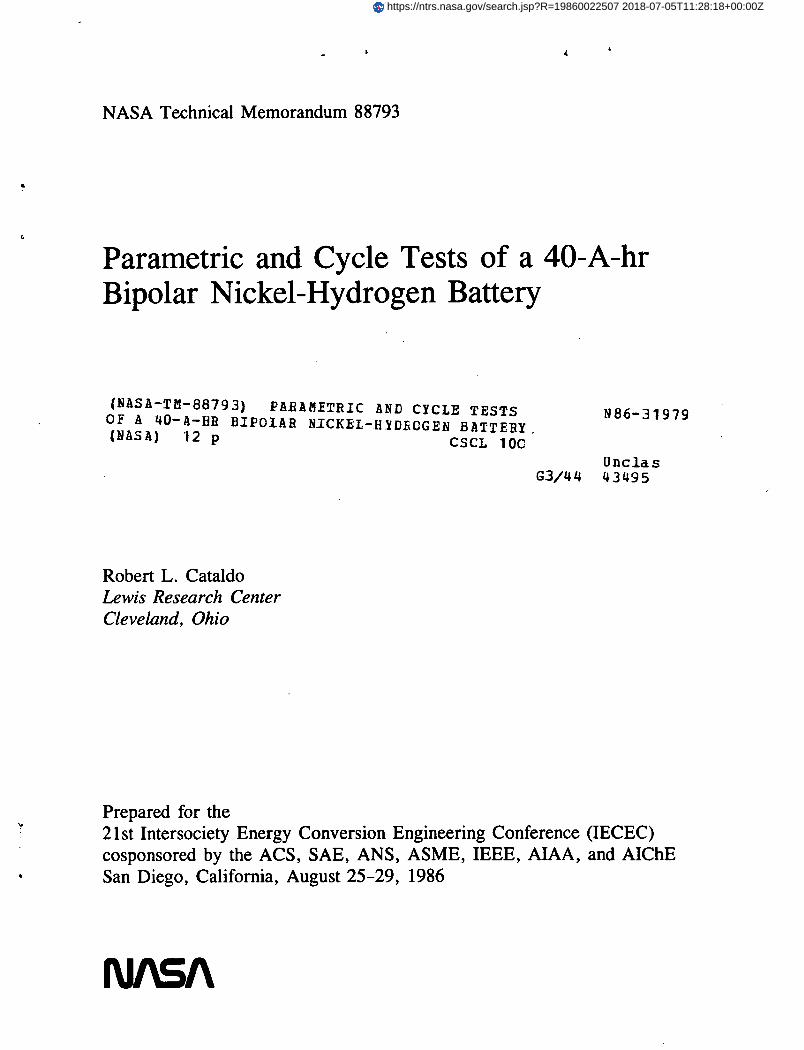
The battery was high rate discharged at both constant and pulsed currentsfor the 250 A (5 C) and 500 A (10 C) rates to a discharge cutoff voltage of6.0 V during the pulse. Both voltage performance and capacity at pulsed con-ditions Increased as shown 1n figure 1. One additional pulse test was to dis-charge the battery at 1500 A (30 C) for 1 sec where a load voltage of 4.0 Vwas established resulting 1n a 6 kW pulse. This value was lower than expectedfrom previous results (ref. 2). This lower value of pulse power and the resultof a dramatic Increase 1n high rate capacity by pulsing compared to constantdischarge level Indicated that possibly the area for hydrogen gas access 1nthe frames was not sufficient to support these high discharge rates. Thisproblem was addressed by redesigning the gas access slots 1n future batteriesfor pulse applications.
Figure 1 also shows plots of the data tabulated 1n table I. Figure 1displays battery voltage and discharge capacity as a function of dischargecurrent at 20 °C. The 12, 50, and 100 A discharge plots are characteristic ofclassical battery performance plots. However, the constant load dischargecurves of 250 and 500 A do not have the standard plateau and knee. This 1sbecause of the high rate discharge and possibly the decrease of hydrogen gasconcentration at the electrode surface. These two tests were repeated bypulse discharging at a 1 sec on, 1 sec off duty cycle. The off, or relaxationtime allows the gas concentration to Increase 1n the gas cavity formed by thehydrogen electrode, gas screen and bipolar plate. The dashed curve 1n Figure1 shows the Increase 1n capacity discharged and the Increase 1n watts and watt-hours. The greatest change 1s noticed of the 250 A level where the hydrogengas concentration depletion 1s less than that of the 500 A rate. An Increase1n ratio of off to on time may have Improved the pulsed performance,particularly at higher rates.
Figure 2 shows the relationship of energy delivered on discharge to bat-tery temperature. The cooling configuration dictates that temperatures wereequal over the entire cell area. A marked Increase 1n energy delivered andcyclic efficiency was observed at the 30 °C data point compared to both higherand lower temperatures. At temperatures lower than 30°, battery voltageIncreases on charge and decreases on discharge causing a net decrease 1n effi-ciency. However, above 30 °C, effects of nickel electrode charging Inefficiencywere seen. These results Indicate that a bipolar battery with Inter-cell,planer cooling plates could operate at a higher thermal system temperaturethan conventional single cell designs that transmit heat 1n a radial directionvia the vessel wall. Therefore, thermal system designs would need to considerthe differences 1n battery design.
Figure 3 shows the battery voltage profile response to pulse dischargesof 500 A. Only the first four pulses are shown here, although 155 pulses(21.5 A-hr) were discharged. The Instantaneous battery voltage drop duringthe pulse Increased from 1.4 to 2.2 V from beginning to end. This Increase 1nvoltage drop Indicates that a 50 percent change 1n effective Internal cellImpedance occurred.
Figure 4 shows the voltage profile for a one pulse maximum power test. A1500 A 1 sec pulse was delivered. Battery voltage, measured at the externalterminals of the vessel, was 4.0 V resulting 1n a power level of 6 kW. The

Instantaneous voltage drop was 8 V for the 1500 A pulse. Using these values,a cell resistance of about 0.5 v« was calculated.
CYCLE TESTS
The battery was cycled at a low-earth-orbit (LEO) regime of 60 m1n chargeand 30-m1n discharge to a depth of 40 percent. The hydrogen pressure was200 ps1 and the coolant temperature was set at 20 °C. The discharge currentwas a constant 4 A and the charge was a constant current of 22 A (10 percentovercharge) for the first 300 cycles. The discharge current and charge currentwere lowered to 32 and 18 A, respectively, because these values were morerepresentative of the actual capacity obtained at the LEO rate.
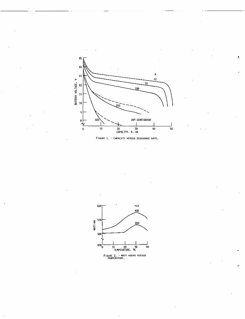
After 100 LEO cycles the amount of overcharge was Increased to 15 percent1n order to maintain proper end-of-d1scharge (EOD) voltages. The EOD voltageof Cell 6 had declined a total of 0.680 V 1n 100 cycles, reaching 0.5 V beforethe 30 m1n discharge was completed. Cell 6 was then Individually charged for16 hr at 5 A (cycle 206) and discharged at 12 A. This capacity check Indicateda 25 to 30 percent loss 1n low-rate capacity to 1.0 V compared to the othernine cells (fig. 5).
The electronic voltage sensors were set to terminate discharge when anycell voltage reached 0.5 V. Therefore, Cell 6 was shunted at cycle 207 with aconductor to avoid overcharging the other cells when Cell 6 would reach 0.5 Vprior to the 30-m1n discharge. The hydrogen electrode was considered as apossible cause of the problem. High discharge polarizations were observedwith this battery as compared to previous bipolar batteries built. The totalhydrogen electrode was comprised of three 8 by 8 1n. sections. If one sectionbecame Inactive due to Improper electrolyte volume, the pattern of currentdensity distribution through the cell would cause an even greater Internalresistance and possibly Inactive areas of the nickel electrode. This Imbalanceof electrolyte volume within the electrode could develop over a period of time.Special testing 1n small cells has Indicated poor discharge performance, resul-ting 1n a decrease 1n discharge capacity 1n cells that were built with whollyor partially defective electrodes. Figure 6 shows a LEO cycle discharge pro-file for Cell 6 at cycle 205, Cell 10 at cycle 3000 and a battery averagedprofile at cycle 3000. The capacity loss of Cell 10 after 3000 cycles hadapproached that of Cell 6 after 205 cycles. However, the slope of the voltageprofile following the knee of the curve for Cell 10 was not as steep as thatof Cell 6 and the voltage had not reached 0.800 V by EOD. The capacity ofCell 10 had declined 30 percent 1n 3000 LEO cycles, but did not affect batterycharge or discharge operation. A problem with a section of hydrogen electrodewas also suspected 1n Cell 10.
The battery continues to life cycle at 40 percent ODD and has accrued3200 cycles as of 5/86. The discharge voltage profiles of the other eightcells have remained unchanged during these cycles and the averaged voltage 1sshown 1n figure 6. The average EOD voltage was 1.18 V. This value was lowerthan expected for a 40 percent 000 and would be typical for 80 percent DOD.The hydrogen electrode vendor was approached on this matter of possible elec-trode problems. A specification change 1n the supplier's materials used forthe electrodes could be the source of these difficulties experienced with thehydrogen electrodes.

Figure 7 shows the voltage and temperature profiles for Cell 1 duringcycle 3000. The temperature shown 1s the center of the nickel electrode 1nCell 1. The temperature plot shows a uniform average cycle temperature with a2-°C rise during the end of charge. This also demonstrates the effectivenessof the cooling design to maintain uniform temperatures throughout the battery.
CONCLUSIONS
The parametric tests conducted on the first actively cooled bipolar nickel-hydrogen battery demonstrates Its feasibility. The results are comparable toprevious Lewis designs except for high rate performance. The pulse tests con-ducted suggest an Insufficient gas access to the hydrogen electrode which hasresulted In Increased polarization. This area has been addressed An otherdesigns for high discharge rates.
The thermal aspects of this battery allow cooling system temperatures ofabout 30 °C for maximum power efficiency. Battery operation 1n this tempera-ture range of 30 °C could have an Impact on solar array and radiator sizing.
The battery has achieved 3200 LEO cycles at 40 percent DOD. The dischargevoltage has shown no degradation, with the exception of Cells 6 and 10 that maycontain defective hydrogen electrodes. The voltage performance of this batterywas less than predicted and hydrogen electrodes with high polarization havebeen Identified as a possible cause. However, a valid data base 1s being gen-erated on the overall concept of an actively cooled bipolar battery.
Lewis 1s working toward establishing a baseline design that would requireonly simple low cost modifications to the baseline design for Integration Intovarious applications. The successful application of active cooling 1s a majorstep 1n developing this baseline design.
REFERENCES
1. Cataldo, R.L.: Design of a 1-kWh Bipolar Nickel-Hydrogen Battery.Advanced Energy Systems - Their Role 1n Our Future, 19th IntersodetyEnergy Conversion Engineering Conference, Vol. ,1, American NuclearSociety, 1984, pp. 264-269.
2. Cataldo, R.L.: Test Results of a Ten Cell Bipolar Nickel-HydrogenBattery. Energy for the Marketplace, 18th Intersodety Energy ConversionEngineering Conference, Vol. 4, American Institute of Chemical Engineers,1983, pp. 1561-1567.

TABLE I. - TABULATED TEST MATRIX DATA AT 200 PSI
Chargerate
CCCC/2C/2C/2
CCCC/2C/2C/2
CCCC/2C/2C/2
CCCC/2C/2C/2
CC/2
Dischargerate
2CCC/42CCC/4
2CCC/42CCC/4
2CCC/42CCC/4
2CC
. C/42CCC/4
i. • - '
CC' •
Temperature,°c
0
1
10
i
20
i
30 .
1
4040
Ampere-hours,out
42.444.449.343.84651.5
43.64651
43.54552
45.547.551.54548
51.5
434650404449
41.841.5
Watt-hours,1n
879882883845845851
856860856831834840
843842818822820820
834834832818813818
824809
Watt-hours,out
468533629469545655
497557648489539656
529582652524587655
505560639470536629
520516
Energyefficiency,
%
536071556477
586575596578
63 .6980647280
606777576677
6364
End-of-dlschargebatteryvoltage
9.310.410.88.810.210.4
9.59.8
10.19.39.99.9
9.510.18.49.59.79.6
1-0.110.59.5
10.5.4
9.7
10.610.5
TABLE II. - TABULATED TEST MATRIX DATA AT 400 PSI
Chargerate
CC/2
CC/2
CC/2
CC/2
CC/2
Dischargerate
CC
CC
CC
CC
CC
Temperature,°C
00
1010
2020
3030
4040
Ampere-hours,out
3739
37.838.5
39.439.6
42.242.2
45.541.8
Watt-hours,1n
890857
870841
851829
836824
827816
Watt-hours,out
452470
466474
490495
523523
569521
Energyefficiency,
%
5155
53.556
5760
62.563.5
6964
End-of-dlschargebatteryvoltage
10.910.7
11.010.8
11.010.8
9.39.1
8.78.9

TABLE III. - CHARACTERIZATION TEST MATRIX
[2 hr, 32.5 A charge; C rate (50 A) discharge.]
Temperature,°C
010203040010203040
Pressurebase,ps1
400400400400400200200200200200
Ampere-hours ,out
44*444648454342424442
Watt-hours,1n
10151000978967980
10181007975970
. 957
Watt-hours,out
514524554575553502502506532510
Watt-hours,eff.,%
5152
56.560
56.54950525553
End-of-d1schargebattery voltage
9.79.99.08.98.99.710
10.39.88.6
15
11
13
jjj 12
§ 10
9
10 20 30 10CAPACITY, A, HR
FIGURE 1. - CAPACITY VERSUS DISCHARGE RATE.
50
6001—
10 20 30TEMPERATURE. °C
FIGURE 2. - HATT-HOURS VERSUSTEMPERATURE.

16
11
12
10
< 500 r—
ON OFF
1 2 3 1 5 6 7 8TIME, SEC
FIGURE 3. - 500 AMPERE PULSE TEST.
1500
1000
500
0
— 15
— => 10
— ° 5
-
—
-
V
/-
6 KW AVERAGEPOWER DELIVERED
° 0TIME. SEC
FIGURE 1. - PEAK POWER TEST.
1.1
1.0
.6
.2
t0
I
AVERAGE
1.0 2.0 3.0 1.0-• TIME, HR
FIGURE 5. - CAPACITY MEASUREMENT, C/1 RATE.
5.0
1.Si-
i.o
AVERAGE
0 30 60 90TIME, MIN
FIGURE 6. - DISCHARGE CELL VOLTAGE PROFILE.
o 30UJO£
| 20
§ 10
TIME, MIN
FIGURE 7. - VOLTAGE AND TEMPERATURE PROFILES FOR CYCLE 3000.

1. Report No.NASA TM-88793
2. Government Accession No. 3. Recipient's Catalog No.
4. Title and Subtitle 5. Report Date
Parametric and Cycle Tests of a 40-A-hr BipolarNickel-Hydrogen Battery 6. Performing Organization Code
506-41-21
7. Authors)
Robert L. Cataldo
8. Performing Organization Report No.
E-3102
10. Work Unit No.
9. Performing Organization Name and Address
National Aeronautics and Space AdministrationLewis Research CenterCleveland, Ohio 44135
11. Contract or Gnint No.
12. Sponsoring Agency Name and Address
National Aeronautics and Space AdministrationWashington, O.C. 20546
13. Type of Report and Period Covered
Technical Memorandum
14. Sponsoring Agency Code
15. Supplementary Notes
Prepared for the 21st Intersodety Energy Conversion Engineering Conference(IECEC), cosponsored by the ACS, SAE, ANS, ASME, IEEE, AIAA, and AIChE, SanDiego, California, August 25-29, 1986.
16. Abstract
A series of tests was performed to characterize battery performance relating to certain operating param-eters which included charge current, discharge current, temperature and pressure. The parameters werevaried to confirm battery design concepts and to determine optimal operating conditions. Spacecraftpower requirements are constantly increasing. Special spacecraft such as the Space Station and platformswill require energy storage systems of 130 and 25 kWh, respectively. The complexity of these high powersystems will demand high reliability, and reduced mass and volume. Candidate electrochemical systemsare regenerative fuel cells, nickel-cadmium batteries and nickel-hydrogen batteries. A system that usesbatteries for storage will require a cell count in excess of 400 units. These cell units must then beassembled into several batteries with over 100 cells in a series connected string. In an attempt tosimplify the construction of conventional cells and batteries, the NASA Lewis Research Center batterysystems group initiated work on a nickel-hydrogen battery in a bipolar configuration in early 1981.Features of the battery with this bipolar construction show promise in improving both volumetric andgravimetric energy densities as well as thermal management. Bipolar construction allows cooling incloser proximity to the cell components, thus heat removal can be accomplished at a higher rejectiontemperature than conventional cell designs. Also, higher discharge current densities are achievablebecause of low cell impedance. Lower cell impedance is achieved via current flow perpendicular to theelectrode face, thus reducing voltage drops in the electrode grid and electrode terminal tabs.
17. Key Words (Suggested by Authors))
Nickel-hydrogen batteries; Bipolar;Characterization; Testing
19. Security Classlf. (of this report)
Unclassified
18. Distribution Statement
Unclassified - unlimitedSTAR Category 44
20. Security Classlf. (of this page)
Unclassif ied21. No. of pages 22. Price*
'For sale by the National Fochnlcal Information Service. Spiinglield, Virglnlu /!2161

National Aeronautics andSpace Administration
Lewis Research CenterCleveland. Ohio 44135
Official BusinessPenalty for Private Use $300
SECOND CLASS MAIL
ADDRESS CORRECTION REQUESTED
Postage and Fees PaidNational Aeronautics andSpace AdministrationNASA-4S1
NASA