parameters for foundation design
TRANSCRIPT
8
Parameters and Criteriafor Foundation Design
8.1 Introduction
The foundation, being an important interface between the superstructure and the soil, has to
safely transfer the large loads and moments coming from the superstructure to the soil at site.
While the superstructure loads depend on the needs of the project, the soil capacities are limited
to its natural properties at site though minor manipulations are possible using suitable but
expensive ground improvement methods. Thus the foundation design needs a very judicial
selection of parameters and design methods and acceptability criteria. Some of these aspects
are discussed in this chapter while the specific considerations for shallow foundations and pile
foundations are presented in Chapters 4–7 and 9–12.
8.2 Design Considerations
There are many aspects to be considered for a proper design of foundations, as outlined in
Chapters 1–3, besides the specific requirements of the particular type of foundation being
designed, as discussed in subsequent chapters. These are broadly classified as follows:
1. Requirements of the project and choice of superstructures.
2. Loads and moments coming from the superstructures.
3. Selection of suitable site.
4. Soil properties at the chosen site.
5. Bearing capacity, settlement and compressibility, stress distribution and lateral pressure
where necessary.
6. Choice of the foundations based on items 2, 4, and 5, as follows:
a. Shallow foundations; spread footings, combined footings, strip footings, mat/raft
foundations.
b. Deep foundations; piles and pile groups, piers (including large diameter piers), well
foundations, that is, caissons, pile–raft systems and others.
Foundation Design: Theory and Practice N. S. V. Kameswara Rao© 2011 John Wiley & Sons (Asia) Pte Ltd. ISBN: 978-0-470-82534-1
c. Foundations subjected to vibratory/dynamic loads. In addition to the normal require-
ment for static loads, additional criteria regarding resonance, dynamic amplitudes,
additional pressures/loads at interfaces, natural frequency, noise due to vibration and so
on, have to be considered for these foundations. These are discussed in Chapter 11.
7. Geotechnical aspects for the design of the selected type of foundations, that is, guided by
items 2, 4, 5, 6 as per codes and practices.
8. Structural design of the foundation based on items 6 and 7 as per standard codes and
practices.
9. Criteria for assessment as per codes, practices and assessment of the structure designed
with respect to criteria based on item 8.
10. Acceptability of the design if the foundation designed satisfies the criteria specified based
on item 8.
11. If the foundation does not satisfy the specified criteria, it has to be redesigned or the soil
properties have to be improved to meet the requirements until the soil and foundation
requirements are acceptable with specified factors of safety.
The items mentioned in 7, 8 and 9 are presented in the following sections while most of the
other aspects are described in the respective chapters of this book.
8.3 Codes, Practices and Standards
All designs, whether foundations, soils or structures, have to meet prescribed codes, practices
and standards. These are developed as per national, provincial, city and local requirements and
have to be complied with for acceptable design and construction practices. Since these are
country-specific, only a few of the most commonly adopted criteria for the design of
foundations are described below.
8.4 Design Soil Pressure
For any foundation design, one of the basic parameters to be computed is the design soil
pressure, that is, the safe pressure that can be borne by the soil when the foundations transmit
the superstructure loads to the soil below. This depends on many foundation factors, such as
shape, size, depth and type, as described in Chapter 3. Even the parameters for design depend
on the method of analysis, that is, conventional or rational methods, as presented in Chapter 4.
While the specific requirements have to be closely studied, broadly the design soil pressure can
be obtained using either the bearing capacity criterion or settlement/differential settlement
criterion. Settlements to be considered are the long term consolidation settlements and bearing
capacity relates to shear/or punching shear failure, as discussed in Chapter 3.
The design pressure also depends on breadth of the foundation, as explained in Section 3.1
(Figure 3.2). Thus, the design pressure is the lower of the allowable/safe bearing capacity
(SBC) value or punching shear (based on shear failure with factor of safety of 3) and the
allowable soil pressure (ASP) based on allowable maximum settlement or differential
settlement (based on consolidation theory), as per prescribed criteria. The details of evaluation
of these values are discussed in Chapters 2 and 3. The following sections present some more
details to provide clarity for the determination of these values.
302 Foundation Design
8.5 Gross and Net Values of the Safe Bearing Capacityand Allowable Soil Pressure
It needs to be noted that Terzaghi’s ultimate bearing capacity equations are developed based on
gross soil pressure, (qult ¼ qu) which includes all loads above the foundation level. Thus it is
the gross pressure that can be considered by the foundation including the overburden pressure
and is based on shear strength of the soil at the foundation level.
However, the settlements are caused only by net increase of effective pressure over the
existing overburden pressure. Thus, the ASP is based on net pressure and is based on
consolidation settlement/differential settlement considerations.
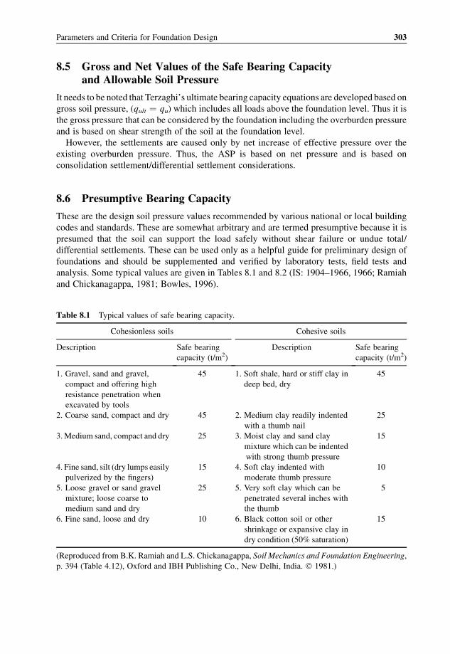
8.6 Presumptive Bearing Capacity
These are the design soil pressure values recommended by various national or local building
codes and standards. These are somewhat arbitrary and are termed presumptive because it is
presumed that the soil can support the load safely without shear failure or undue total/
differential settlements. These can be used only as a helpful guide for preliminary design of
foundations and should be supplemented and verified by laboratory tests, field tests and
analysis. Some typical values are given in Tables 8.1 and 8.2 (IS: 1904–1966, 1966; Ramiah
and Chickanagappa, 1981; Bowles, 1996).
Table 8.1 Typical values of safe bearing capacity.
Cohesionless soils Cohesive soils
Description Safe bearing
capacity (t/m2)
Description Safe bearing
capacity (t/m2)
1. Gravel, sand and gravel,
compact and offering high
resistance penetration when
excavated by tools
45 1. Soft shale, hard or stiff clay in
deep bed, dry
45
2. Coarse sand, compact and dry 45 2. Medium clay readily indented
with a thumb nail
25
3.Medium sand, compact and dry 25 3. Moist clay and sand clay
mixture which can be indented
with strong thumb pressure
15
4. Fine sand, silt (dry lumps easily
pulverized by the fingers)
15 4. Soft clay indented with
moderate thumb pressure
10
5. Loose gravel or sand gravel
mixture; loose coarse to
medium sand and dry
25 5. Very soft clay which can be
penetrated several inches with
the thumb
5
6. Fine sand, loose and dry 10 6. Black cotton soil or other
shrinkage or expansive clay in
dry condition (50% saturation)
15
(Reproduced from B.K. Ramiah and L.S. Chickanagappa, Soil Mechanics and Foundation Engineering,
p. 394 (Table 4.12), Oxford and IBH Publishing Co., New Delhi, India. � 1981.)
Parameters and Criteria for Foundation Design 303
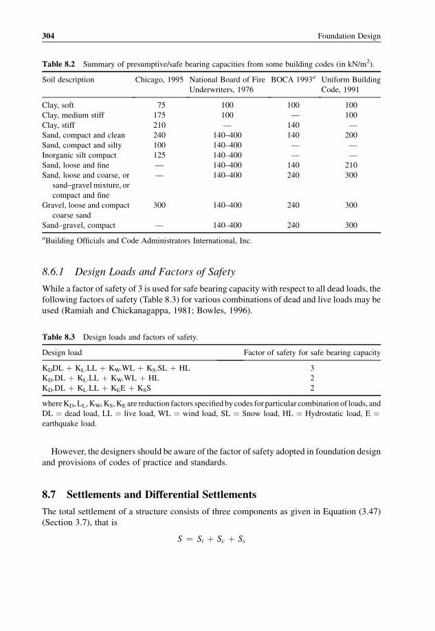
8.6.1 Design Loads and Factors of Safety
While a factor of safety of 3 is used for safe bearing capacity with respect to all dead loads, the
following factors of safety (Table 8.3) for various combinations of dead and live loads may be
used (Ramiah and Chickanagappa, 1981; Bowles, 1996).
However, the designers should be aware of the factor of safety adopted in foundation design
and provisions of codes of practice and standards.
8.7 Settlements and Differential Settlements
The total settlement of a structure consists of three components as given in Equation (3.47)
(Section 3.7), that is
S ¼ Si þ Sc þ Ss
Table 8.2 Summary of presumptive/safe bearing capacities from some building codes (in kN/m2).
Soil description Chicago, 1995 National Board of Fire
Underwriters, 1976
BOCA 1993a Uniform Building
Code, 1991
Clay, soft 75 100 100 100
Clay, medium stiff 175 100 — 100
Clay, stiff 210 — 140 —
Sand, compact and clean 240 140–400 140 200
Sand, compact and silty 100 140–400 — —
Inorganic silt compact 125 140–400 — —
Sand, loose and fine — 140–400 140 210
Sand, loose and coarse, or
sand–gravel mixture, or
compact and fine
— 140–400 240 300
Gravel, loose and compact
coarse sand
300 140–400 240 300
Sand–gravel, compact — 140–400 240 300
aBuilding Officials and Code Administrators International, Inc.
Table 8.3 Design loads and factors of safety.
Design load Factor of safety for safe bearing capacity
KDDL þ KL.LL þ KW.WL þ KS.SL þ HL 3
KD.DL þ KL.LL þ KW.WL þ HL 2
KD.DL þ KL.LL þ KEE þ KSS 2
whereKD, LL,KW,KS,KE are reduction factors specified by codes for particular combination of loads, and
DL ¼ dead load, LL ¼ live load, WL ¼ wind load, SL ¼ Snow load, HL ¼ Hydrostatic load, E ¼earthquake load.
304 Foundation Design
where
Si ¼ immediate/elastic settlement
Sc ¼ settlement due to primary consolidation
Ss ¼ settlement due to secondary consolidation
Out of these, usually the consolidation (primary) settlement Sc is the most important part of the
total settlement as discussed in Section 3.7. Though theremay not be a collapse or shear failure of
the soil due to large settlement, the structures and foundationsmay become unserviceable. Further
tilting and cracking of beams and slabsmay occur due to differential settlements. These are shown
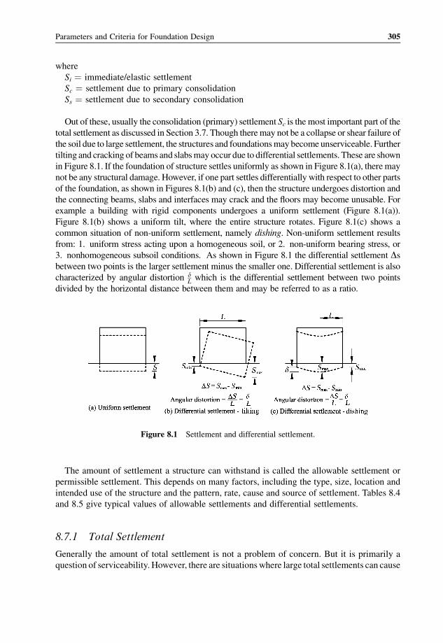
in Figure 8.1. If the foundation of structure settles uniformly as shown in Figure 8.1(a), theremay
not be any structural damage. However, if one part settles differentially with respect to other parts
of the foundation, as shown in Figures 8.1(b) and (c), then the structure undergoes distortion and
the connecting beams, slabs and interfaces may crack and the floors may become unusable. For
example a building with rigid components undergoes a uniform settlement (Figure 8.1(a)).
Figure 8.1(b) shows a uniform tilt, where the entire structure rotates. Figure 8.1(c) shows a
common situation of non-uniform settlement, namely dishing. Non-uniform settlement results
from: 1. uniform stress acting upon a homogeneous soil, or 2. non-uniform bearing stress, or
3. nonhomogeneous subsoil conditions. As shown in Figure 8.1 the differential settlement Dsbetween two points is the larger settlement minus the smaller one. Differential settlement is also
characterized by angular distortion dLwhich is the differential settlement between two points
divided by the horizontal distance between them and may be referred to as a ratio.
The amount of settlement a structure can withstand is called the allowable settlement or
permissible settlement. This depends on many factors, including the type, size, location and
intended use of the structure and the pattern, rate, cause and source of settlement. Tables 8.4
and 8.5 give typical values of allowable settlements and differential settlements.
8.7.1 Total Settlement
Generally the amount of total settlement is not a problem of concern. But it is primarily a
question of serviceability. However, there are situationswhere large total settlements can cause
Figure 8.1 Settlement and differential settlement.
Parameters and Criteria for Foundation Design 305
serious problems, for example, a tank on soft clay near a waterfront can settle below the water
level. The allowable total settlements are given in several building codes and the values
specified by IS: 1904–1966 are illustrated in Table 8.4. The table also gives a range of values for
permissible differential settlement.
8.7.2 Differential Settlement
It is usually the differential settlement (rather than the total settlement) that is important in the
designing of a foundation as the consequences of differential settlement are more detrimental.
The magnitude of differential settlement is affected greatly by the nonhomogeneity of natural
soils and also by the ability of foundation to bridge over soft soil. Theoretical settlement should
be computed for various points in a structure, such as center, corner, lightest and heaviest
column locations, in order to compute differential settlement. The allowable angular distor-
tions in buildings have been given in several codes and research reports (Ramiah and
Chickanagappa, 1981; Bowles, 1996; Das, 2007). Some useful values given by Skempton
(1956) are presented in Table 8.5.
Table 8.4 Permissible settlement as per Indian Standards.
Criterion Permissible settlement (cm)
Angular distortion: office buildings,
flats and factories
Differential settlement (as a ratio)
should not exceed 1/500–1/1000
Maximum differential settlement:
Clays 4.0
Sands 2.5
Maximum total settlement:
Isolated footings on clay 6.5
Isolated footings on sand 4.0
Raft foundations on clay 6.5–10.0
Raft foundation on sand 4–6.5
(Reproduced from B.K. Ramiah and L.S. Chickanagappa, Soil Mechanics and
Foundation Engineering, p. 406 (Table 4.27), Oxford and IBH Publishing Co.,
New Delhi, India. � 1981.)
Table 8.5 Permissible maximum total and differential settlements of buildings (in cms).
Criterion Isolated foundations Rafts
Angular distortion 1/300
Greatest differential settlement (cm)
Clays 4.44 (3.81)
Sands 3.17 (2.54)
Maximum settlement (cm)
Clays 7.5 (6.35) 7.5–12.5 (6.35–10.0)
Sands 5.0 (3.81) 5.0–7.5 (3.81–6.35)
Note: The values in parenthesis take into account a safety factor of 1.25.
(A.W. Skempton and D.H. MacDonald, “The allowable settlements of buildings,” Proceedings of the
Institution of Civil Engineers, London, part III, vol. 5, pp. 759–760, � 1956, with permission from The
Institution of Civil Engineers (ICE), Thomas Telford Ltd.)
306 Foundation Design
8.8 Cracks Due to Uneven Settlement
Uneven settlement creates cracks in connecting structural components such as beams and
slabs. Even connecting walls and slabs develop cracks due to these uneven settlements. The
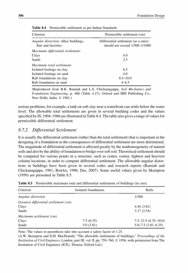
cracks usually develop in the diagonal direction though vertical cracks are also possible. They
may start from top if one end of the wall settles more than the next, as shown in Figures 8.2(a)
and (b). If the middle part of the wall settles more than the ends, then cracks may start from the
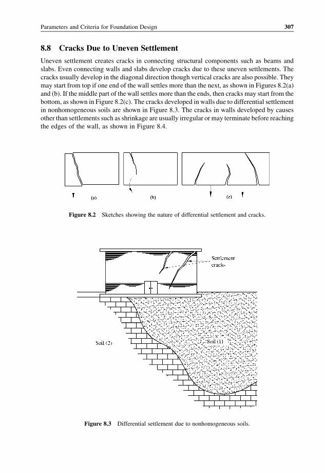
bottom, as shown in Figure 8.2(c). The cracks developed in walls due to differential settlement
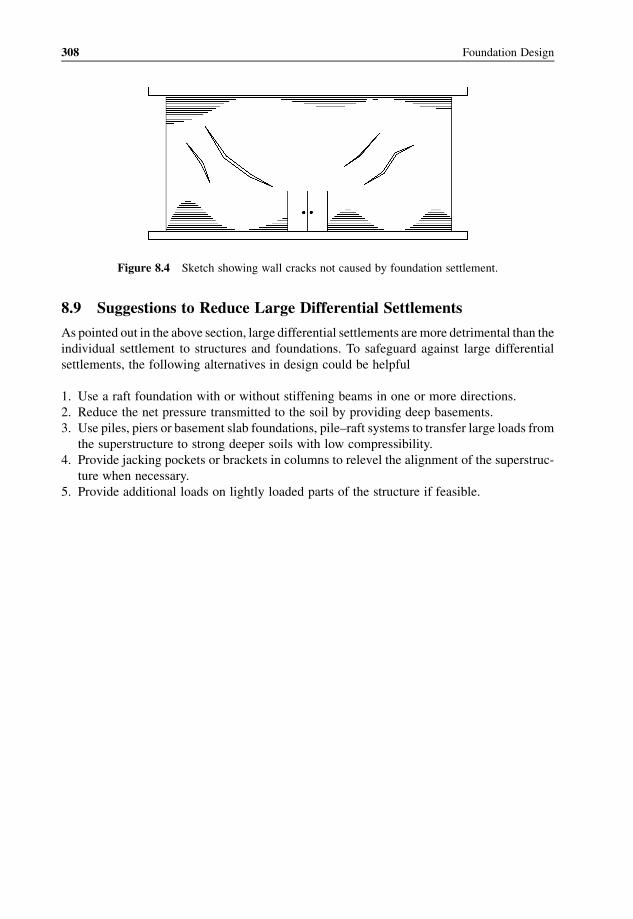
in nonhomogeneous soils are shown in Figure 8.3. The cracks in walls developed by causes
other than settlements such as shrinkage are usually irregular or may terminate before reaching
the edges of the wall, as shown in Figure 8.4.
Figure 8.2 Sketches showing the nature of differential settlement and cracks.
Figure 8.3 Differential settlement due to nonhomogeneous soils.
Parameters and Criteria for Foundation Design 307
8.9 Suggestions to Reduce Large Differential Settlements
As pointed out in the above section, large differential settlements are more detrimental than the
individual settlement to structures and foundations. To safeguard against large differential
settlements, the following alternatives in design could be helpful
1. Use a raft foundation with or without stiffening beams in one or more directions.
2. Reduce the net pressure transmitted to the soil by providing deep basements.
3. Use piles, piers or basement slab foundations, pile–raft systems to transfer large loads from
the superstructure to strong deeper soils with low compressibility.
4. Provide jacking pockets or brackets in columns to relevel the alignment of the superstruc-
ture when necessary.
5. Provide additional loads on lightly loaded parts of the structure if feasible.
Figure 8.4 Sketch showing wall cracks not caused by foundation settlement.
308 Foundation Design