parallel reactive molecular dynamics: numerical … · parallel reactive molecular dynamics:...
TRANSCRIPT

Purdue UniversityPurdue e-PubsPRISM: NNSA Center for Prediction of Reliability,Integrity and Survivability of Microsystems Birck Nanotechnology Center
1-1-2009
Parallel Reactive Molecular Dynamics: NumericalMethods and Algorithmic TechniquesHasan Metin AktulgaPurdue University - Main Campus, [email protected]
Joseph C. FogartyUniversity of South Florida
Sagar A. PanditUniversity of South Florida
Ananth Y. GramaPurdue University, [email protected]
Follow this and additional works at: http://docs.lib.purdue.edu/prismPart of the Nanoscience and Nanotechnology Commons
This document has been made available through Purdue e-Pubs, a service of the Purdue University Libraries. Please contact [email protected] foradditional information.
Aktulga, Hasan Metin; Fogarty, Joseph C.; Pandit, Sagar A.; and Grama, Ananth Y., "Parallel Reactive Molecular Dynamics: NumericalMethods and Algorithmic Techniques" (2009). PRISM: NNSA Center for Prediction of Reliability, Integrity and Survivability ofMicrosystems. Paper 18.http://docs.lib.purdue.edu/prism/18

Parallel Reactive Molecular Dynamics: Numerical Methods and
Algorithmic Techniques
Hasan Metin Aktulga ∗ Joseph C. Fogarty † Sagar A. Pandit ‡
Ananth Y. Grama §
October 21, 2010
Abstract
Molecular dynamics modeling has provided a powerful tool for simulating and understanding diversesystems – ranging from materials processes to biophysical phenomena. Parallel formulations of thesemethods have been shown to be among the most scalable scientific computing applications. Many in-stances of this class of methods rely on a static bond structure for molecules, rendering them infeasible forreactive systems. Recent work on reactive force fields has resulted in the development of ReaxFF, a novelbond order potential that bridges quantum-scale and classical MD approaches by explicitly modeling bondactivity (reactions) and charge equilibration. These aspects of ReaxFF pose significant challenges froma computational standpoint, both in sequential and parallel contexts. Evolving bond structure requiresefficient dynamic data structures. Minimizing electrostatic energy through charge equilibration requiresthe solution of a large sparse linear system with a shielded electrostatic kernel at each sub-femtosecondlong timestep. In this context, reaching spatio-temporal scales of tens of nanometers and nanoseconds,where phenomena of interest can be observed, poses significant challenges.
In this paper, we present the design and implementation details of the Purdue Reactive MolecularDynamics code, PuReMD. PuReMD has been demonstrated to be highly efficient (in terms of processorperformance) and scalable. It extends current spatio-temporal simulation capability for reactive atomisticsystems by over an order of magnitude. It incorporates efficient dynamic data structures, algorithmicoptimizations, and effective solvers to deliver low per-timestep simulation time, with a small memoryfootprint. PuReMD is comprehensively validated for performance and accuracy on up to 3K cores ona commodity cluster (DoE/LLNL/Hera). Potential performance bottlenecks to scalability beyond ourexperiments have also been analyzed. PuReMD is available over the public domain and has been used tomodel diverse systems, ranging from strain relaxation in Si-Ge nanobars, water-silica surface interaction,and oxidative stress in lipid bilayers (biomembranes).
1 Introduction
Conventional atomistic modeling techniques rely on quantum-mechanical methods or on traditional molec-ular dynamics approaches. Quantum-scale modeling requires computationally expensive solution of theelectronic Schrodinger equation, restricting its applicability to systems on the order of thousands of atomsand picosecond simulation timeframes. Classical molecular dynamics (MD) approaches, on the other hand,overcome the time and size limitations of quantum methods by approximating the nucleus together with itselectrons into a single basis. These methods rely on careful parametrization of various atomic interactionscorresponding to bonds, valence angles, torsion, van der Waals interactions, etc. based on detailed quantum
∗Department of Computer Science, Purdue University, West Lafayette IN 47907 ([email protected])†Department of Physics, University of South Florida, Tampa, FL 33620 ([email protected])‡Department of Physics, University of South Florida, Tampa, FL 33620 ([email protected])§Department of Computer Science, Purdue University, West Lafayette, IN 47907 ([email protected])
1

mechanical simulations. In spite of these approximations, classical MD methods have been successful inelucidating various phenomena inaccessible to either quantum methods or to experiments.
Classical MD approaches typically rely on static bonds and fixed partial charges associated with atoms.These constraints limit their applicability to non-reactive systems only. A number of recent efforts haveaddressed this limitation [1, 2, 3, 4, 5]. Among these, ReaxFF, a novel reactive force field developed byvan Duin et al[6], bridges quantum-scale and classical MD approaches by explicitly modeling bond activity(reactions) and charge equilibration. The flexibility and transferability of the force field allows ReaxFF tobe easily extended to systems of interest. Indeed, ReaxFF has been successfully applied to diverse systems,ranging from materials modeling to biophysical systems [6, 7, 8, 9].
ReaxFF is a classical MD method in the sense that atomic nuclei, together with their electrons, aremodeled as basis points. Interactions among atoms are modeled through suitable parametrizations andatomic motion obeys laws of classical mechanics. Accurately modeling chemical reactions, while avoidingdiscontinuties on the potential energy surface, however, requires more complex mathematical formulationsof interactions than those in most classical MD methods (bond, valence angle, dihedral, van der Waalspotentials). In a reactive environment in which atoms often do not achieve their optimal coordinationnumbers, ReaxFF requires additional modeling abstractions such as lone pair, over/under-coordination,and 3-body and 4-body conjugation potentials, which further increase its computational complexity. Thisincreased computational cost of bonded interactions (due to the reconstruction of all bonds, 3-body and4-body structures at each time-step and much more complex bonded interaction formulations) approachesthe cost of nonbonded interactions for ReaxFF, as we discuss in section 5. Note that for typical conventionalMD codes, the time spent on bonded interactions is significantly lower than that spent on nonbondedinteractions [27].
An important part of ReaxFF is the charge equilibration procedure. Charge equilibration (QEq) proce-dure [18] approximates the partial charges on atoms by minimizing the electrostatic energy of the system.Charge equilibration is mathematically formulated as the solution of a large sparse system of equations.This solve needs to be performed accurately at each time-step – since it significantly impacts forces and totalenergy of the system. Since partial charges on atoms are fixed in conventional MD, this is not a considerationfor conventional methods. The time-step lengths for ReaxFF simulations is typically an order of magnitudesmaller than conventional MD (tenth of femtoseconds as opposed to femtoseconds), therefore scaling the solveassociated with charge equilibration is a primary design consideration for parallel formulations of ReaxFF.Suitably accelerated Krylov subspace methods are used for this purpose (see Section 4.5). One of the majorchallenges overcome by our effort is the scaling of this solve to thousands of processing cores.
In this paper, we present the design and implementation details of the PuReMD (Purdue ReactiveMolecular Dynamics) code, along with a comprehensive evaluation of its performance on a large commoditycluster (Hera at the Department of Energy/ Lawrence Livermore National Lab) using over 3K processingcores. PuReMD incorporates several algorithmic and numerical innovations to address significant computa-tional challenges posed by ReaxFF. It achieves excellent per time-step execution times, enabling nanosecond-scale simulations of large reactive systems (Section 5). Using fully dynamic interaction lists that adapt to thespecific needs of simulations, PuReMD achieves low memory footprint. Our tests demonstrate that PuReMDis upto five times faster than competing implementations, while using significantly lower memory.
The rest of this paper is organized as follows: We overview related work on parallel ReaxFF in Section 2.In Section 3, we discuss critical design choices for parallelization of ReaxFF. In Section 4, we outline variousalgorithms and numerical techniques used to achieve excellent computational times per simulation timestep.We comprehensively analyze the performance of PuReMD in Section 5. We conclude with a discussion of po-tential bottlenecks to further scaling, solutions to these bottlenecks, and techniques for further improvementsto overall simulation time.
2 Related Work
The first-generation ReaxFF implementation of van Duin et al. [6] demonstrated the validity of the methodin the context of various applications. Thompson et al. [10] successfully ported this initial implementation,
2

(a)
(b)
(c)
Figure 1: Applications using PuReMD: (a) Si-Ge nanobar system, (b) Water-Silica interface, (c) lipid bilayersystem.
which was not developed for a parallel environment, into their parallel MD package LAMMPS [12]. Except forthe charge equilibration part, the ReaxFF implementation in LAMMPS is based on the original FORTRANcode of van Duin [6], significant portions of which were included directly (as Fortran routines called fromC++) to insure consistency between the two codes since the Fortran ReaxFF underwent rapid developmentat the time. Thus the LAMMPS implementation does not take advantage of certain optimizations describedin this paper. The charge equilibration calculation currently in LAMMPS uses a standard parallel conjugategradient algorithm for sparse linear systems [11]. Indeed, efforts are under way to integrate our kernel parallelReaxFF functions into LAMMPS, in close collaboration with Aidan Thompson at Sandia National Labs.Our preliminary tests on the sample systems discussed in this paper reveal that PuReMD is up to five timesfaster than LAMMPS on a single processor. Detailed single-processor performance comparisons of the twocodes are presented in [15]. In Section 5, we present comparisons of LAMMPS and PuReMD codes underweak and strong scaling scenarios.
To the best of our knowledge, the only other reported parallel ReaxFF formulation is due to Nomuro etal. [14]. This paper demonstrates good scaling results. However, its per-timestep-per-atom execution timesare up to an order of magnitude slower than the results we report in this paper. Consequently, even though,their reported efficiencies at approximately 3K cores are higher than ours (our code achieves about 80%efficiency), their simulation time is significantly higher than that reported in this paper.
PuReMD is a publicly available parallel ReaxFF implementation with demonstrated scalability to thou-sands of processing cores. It has been validated by us and by other research groups on diverse systems,ranging from strain relaxation in Si-Ge nanobars [16], water-silica systems [17], and oxidative stress in lipidbilayers (membranes) (Fig. 1).
3

3 Parallel Formulation of ReaxFF
In this section, we discuss the two important aspects of parallel ReaxFF implementation – problem decompo-sition and inter-process synchronization/ communication. We refer to the domain of simulation specified inthe input files as the simulation box, and the part assigned to a process as the sub-domain of that process. Asignificant fraction of the computation associated with an atom involves other atoms within a prescribed dis-tance from the source atom. To facilitate these computations, we construct a list of neighbors for each atom.These neighbor lists are generated by embedding a 3D grid within each process’ sub-domain. Partitionsinduced by this 3D grid are called cells or grid cells.
Domain partitioning and inter-process communication are determined by the mathematical formulationsof various interactions in ReaxFF. Precise mathematical details of the energy and force formulations inReaxFF are beyond the scope of this paper; we refer the readers to the original ReaxFF formulation describedin [6]. An important aspect of ReaxFF that significantly impacts design choices is that it uses shieldedelectrostatics, modeled by range-limited pairwise interactions with Taper corrections. This obviates theneed for computation of long range electrostatic interactions.
3.1 Problem Decomposition
Commonly-used decomposition techniques for MD simulations include atom decomposition, interaction de-composition, and domain decomposition. The specific choice among these is influenced by the character-istics of the force field, with a view to minimizing communication overhead and load imbalance. Whileatom and force decomposition techniques deliver good load balance, movement of atoms and associated dataresults in a highly dynamic inter-process communication pattern. This is generally handled by periodicre-decompositions. However, the simplicity of domain decomposition techniques coupled with its naturalhandling of the range-limited interactions make it a popular choice [25, 26, 23]. Load balancing in domaindecomposition is achieved by suitably partitioning the simulation box into sub-domains with equal compu-tational load. Volumes of sub-domains are altered dynamically to ensure equal workload among processesas the simulation progresses.
Atom or force decomposition techniques are not well-suited to ReaxFF implementations due to thedynamic nature of bonds. The presence of charge equilibration and associated linear system solve, whichtakes up a significant portion of the total simulation time, poses additional considerations not present inconventional MD codes. PuReMD adopts a 3D domain decomposition technique with wrap-around links (atorus) for periodic boundary conditions. This domain decomposition also induces a partition of the degreesof freedom for parallel charge equilibration.
3.2 Boundary Regions
In addition to domain decomposition, a number of other design choices critically impact the performance ofPuReMD. These primarily relate to handling of inter-process communication and synchronizations.
• Interactions spanning process boundaries: In order to avoid unnecessary computation whileensuring accurate calculation of energy and forces resulting from interactions spanning process bound-aries, an efficient coordination mechanism among processes must be designed. Since interactions areprimarily range-limited, a shell of the process’ sub-domain is associated with inter-process interactions.We refer to this shell as the outer-shell. Handling communication (one-sided vs. symmetric data trans-fers) and computation (redundant computation of symmetric terms vs. communication of computedterms) associated with the outer shell impact performance.
• Inter-process communication: Once we determine atoms that must be communicated based on theouter-shell type chosen, communication can take place either through direct messaging or in a stagedmanner [26].
We now discuss these issues in more detail and explain how we handle each in PuReMD.
4

3.2.1 Interactions Spanning Multiple Processes
We first describe our handling of interactions that span multiple processes, since this motivates our choiceof the outer-shell type. We specifically focus on bond-order potentials, and associated dynamic bondedinteractions in ReaxFF. Handling range-limited non-bonded interactions have already been well-studied inliterature [25, 24, 26]. After carefully analyzing different ways of handling bonded interactions in ReaxFFthat span multiple processes, we outline the scheme used in PuReMD below:
• Bond(i,j): The process that owns the atom with the smaller index (indices are unique and aredetermined by a field in the input file) handles the bond.
• LonePair(i): This is a single body potential and the owner of atom i computes the energy and forcesresulting from the unpaired electrons of atom i.
• Over/Under-coordination(i): These are multi-body interactions, directly involving all bondedneighbors of atom i, computed by the owner of i.
• Valence Angle(i,j,k): This includes the valence angle, penalty, and three-body conjugation poten-tials, all of which are computed by the owner of middle atom j.
• Dihedral Angle(i,j,k,l): This includes the torsion and four-body conjugation potentials, both ofwhich are handled by the owner of middle atom with the smaller index. Middle atoms here are j andk.
• Hydrogen Bond(x,H,z): The presence of a dynamic bond between atoms x and H implies that theowner of H atom computes this hydrogen bond interaction.
• Nonbonded(i,j): As in the bonded case, the owner of the atom with the smaller index computes thevan der Waals and Coulomb interactions between atoms i and j.
Establishing this coordination mechanism enables us to avoid double (or multiple) computation of in-teractions straddling process boundaries. The ratio of such interactions to those entirely within processsub-domains can be significant, especially as sub-domain volumes decrease. The potential drawback of thisapproach is the return messages containing forces required at the end of each time-step, when processesneed to compute the total forces on their assigned atoms. We adopt this approach in PuReMD, since forcecomputations in ReaxFF are relatively expensive compared to associated additional communication.
While we avoid double computations for expensive potential terms, we perform redundant computationsin order to avoid the reverse communication during the matrix-vector multiplications associated with thecharge-equilibration solve. This strategy results in slightly worse performance on small numbers of process-ing cores due to redundant computations; however, it delivers better performance by eliminating a costlycommunication step as we scale to larger number of cores.
3.2.2 Choosing the Outer-Shell
The range-limited nature of force fields, associated symmetries, and relative speed of computation andcommunication of a parallel platform motivate the choice of full-shell, half-shell, midpoint-shell or neutralterritory (zonal) methods [28], see (Fig. 2). In full-shell methods, interactions between atoms i and jare computed at processes that hold atoms i and j. This implies that data needed to compute theseinteractions must be symmetrically exchanged, resulting in higher communication. However, where suchinteractions are symmetric, the results do not need to be communicated. In half-shell methods, interactionsbetween atoms i and j are computed at the process responsible for atom i or j. This choice is uniformlyenforced by convention (in our case for example, the process that owns the atom with the lower index).The communication overheads associated with a half-shell implementations is lower since the data requireddoes not need to be symmetrically exchanged. In mid-point method, the interaction between i and j iscomputed by the process which owns the geometric mid-point of i and j. This method requires the exchange
5

br
br
br/2
br
(a) (b)
(c)
(d)
Figure 2: Different outer-shell types commonly used in MD codes shown in 2D for purposes of simplicity:(a) full-shell, (b) half-shell, (c) midpoint-shell, (d) an example NT method: tower-plate shell. In all caseswe assume the process sub-domain to be an orthogonal cube whose sides have length b. r denotes the widthof the outer-shell.
of a thinner outer-shell thereby reducing the communication bandwidth requirements. Finally in neutralterritory methods, forces between atoms i and j are not necessarily calculated by processes that own eitheratom. These methods have been shown to yield lower communication overheads by making very efficientuse of data communicated between processes. However, their applicability is resricted to the context ofrange-limited N-body simulations.
To motivate our choice of the outer shell, we illustrate in Fig. 3, position information of atoms atneighboring process (P2) required by a process (P1) to compute all ReaxFF interactions that it is responsiblefor, based on the conventions we have adopted in Section 3.2.1. In ReaxFF, there are different cut-offdistances for different types of interactions: rbonded is the distance cut-off for determining bonds, rhbond
is the distance between the donor and acceptor in a Hydrogen bond interaction and finally rnonb denotesthe cut-off distance for non-bonded interactions. Taking the maximum spans among all interactions, wedetermine the outer-shell width rshell as:
rshell = max(3× rbond, rhbond, rnonb) (1)
A careful inspection of Fig. 3 reveals that the nature of bonded interactions in ReaxFF does not allow the useof half-shell boundaries or zonal methods. Due to over/under-coordination and valence angle interactions,even when the midpoint boundary method is used, rshell does not shrink at all. Consequently, we use thefull-shell scheme in spite of its higher communication cost.
3.2.3 Inter-process Communication
With the choice of 3D domain decomposition scheme and full-shell type for the outer-shells of processes, inter-process communication can be performed using either direct messaging or staged messaging schemes (seeFig. 4). In direct messaging, every process prepares a separate message for each of its neighbors containing
6

P1 P2bond(i,j)
lone-pair(i)
over/under-coord(i)
valence angle(i,j,k)
dihedral angle(i,j,k,l)
hbond(x,h,z)
= 2 rbond_cut
= 2 rbond_cut
= 3 rbond_cut
nonbonded(i,j)
= 3 rbond_cut
= 3 rbond_cut
= rHbond_cut
= rnonb_cut
Figure 3: Handling of each interaction in ReaxFF when it spans multiple processes. Blue colored circlesrepresent atoms that directly participate in the interaction. Gray colored circles represent atoms that directlyor indirectly affect the interaction’s potential and therefore experience some force due to it. We show onlysuch atoms in the neighboring process for clarity. Lighter tones imply weaker interaction. Next to eachinteraction, we note its maximum span in terms of the cut-off distances in ReaxFF.
the required data and sends these messages using point-to-point communication primitives. The upside ofthis scheme is that communication and computation can be overlapped, i.e., after preparing and sending amessage using a non-blocking send operation, a process can immediately start preparing the message for itsnext neighbor without having to wait for the completion of the send operation. The downside is the numberof messages that need to be sent by each process. Even when we restrict the sub-domain dimensions to begreater than rshell, each process needs to talk to 26 other processes (three-cube minus the self box) and thecommunication pattern does not truly follow the 3D torus topology that we adopt.
In the staged messaging scheme, every process sends/receives messages along a single dimension in eachstage. In a three-stage communication scheme, for example, each process sends/receives atoms in -x, +xdimensions first, then in -y, +y dimensions and finally in -z, +z dimensions; at each stage augmenting itssubsequent messages with the data it receives in previous stages. The upside of this scheme is that eachprocess needs to communicate with few other processes (this scheme would require only 6 messages to besent/received, compared to the 26 send/receives with the direct messaging scheme above). Moreover, thecommunication pattern respects the 3D torus topology which assumes direct connections between nodes in-x, +x, -y, +y, -z and +z directions only. However, the staged messaging scheme requires a stop-process-forward mechanism that does not allow overlapping communication and computation. For example, whena process receives its messages in -x, +x directions, it needs to sort the incoming data to determine what
7

(a) Direct messaging in 2D
Processor sub-domain
Export region
Import region
(b) Staged messaging in 2D
Processor sub-domain
Export in stage2Export in stage1
Import in stage2Import in stage1
stage1 stage1
stage2
stage2
Figure 4: Direct messaging vs staged messaging shown in 2D for simplicity.
1e-05
0.0001
0.001
0.01
0.1
1
1 10 100
time
per a
tom
per
ste
p (m
s)
num cores
staged totaldirect total
staged QEqdirect QEq
staged commdirect comm
Figure 5: Comparison of PuReMD performances using staged vs. direct messaging schemes. We present thetotal time performance together with communication bound parts in each case: QEq and comm (explainedin Section 5)
needs to be forwarded in -y, +y, -z, +z directions.Since both schemes have benefits and overheads that are hard to quantify in a platform-independent
manner, we implement both schemes and perform strong scaling tests using both schemes. We present theresults of this comparison in Fig. 5; details of the simulations are presented in Section 5. The performanceof the two schemes is almost identical upto 64 cores. Beyons this, the staged messaging scheme clearly
8

outperforms direct messaging. Ironically, when we reach 512 cores, total time required using staged messagingis almost equal to the charge equilibration time of direct messaging. At this point, while direct messagingshows signs of hitting the scalability barrier, staged communication scheme’s curve suggests that it can scalenicely to larger number of cores. Based on these experiments, PuReMD uses a staged messaging schemefor all communications between neighbor processes. In fact, other MD packages such as Desomnd [26] andLAMMPS [12] use similar messaging schemes as well.
4 Algorithmic and Numerical Techniques
PuReMD features several algorithmic and numerical techniques to achieve excellent per-timestep executiontime. Its fully dynamic and adaptive interaction lists further improve performance and enable the simulationof large systems on platforms with limited resources. In this section, we provide a summary of the algorithmsand techniques used; for a more comprehensive description of these techniques, we refer readers to [15].
4.1 Generation of Neighbors Lists
As in most MD codes, we use the method of binning for efficiently generating neighbor lists for atoms. Thisrequires construction of a 3D grid within each process’ sub-domain. Based on their spatial coordinates, eachatom is mapped into its corresponding cell. In order to discover neighbors of an atom, it is sufficient to searchwithin the neighboring/nearby cells (provided bin-sizes are suitably selected). Empirically, we determine thatsetting the dimensions of grid cells to half of the neighbor cut-off distance rnbrs yields best performance.Furthermore, reordering atoms so that atoms mapped to the same grid cell are clustered together in theatom list improves the performance of neighbor generation due to cache effects. This reordering also hassignificant impact on the performance of force computation routines and matrix-vector multiplications incharge equilibration. Reordering atoms also allows us to cut the number of look-ups in neighboring cellsby half, on average. This is because it is enough for each atom to search for its neighbors inside onlyneighboring cells that contain atoms with higher indices in the reordered atom list. We further reduce thenumber of neighbor cell look-ups by first checking the distance between the atom and the closest point of theneighboring cell to that atom. All these optimizations give us a very efficient neighbor generation procedure.
4.2 Eliminating Bond Order Derivative Lists
All bonded potentials (including the hydrogen bond potential) depend on the bond order (or bond strength)between atoms. Bond order concept which constitutes the heart of the dynamic bonding scheme in ReaxFFdepends on the type of the two atoms forming the bond, the distance between them and the presence ofother atoms within the bond cut-off distance rbond. Consequently, all forces arising from bonded interactionsdepend on the derivative of the bond order terms [6].
Let BOij denote the bond between atoms i and j. The strength of this bond is affected by the presenceof other atoms around atoms i and j. Therefore, the expression dBOij/drk would evaluate to a non-zerovalue for all atoms k that share a bond with either atom i or j. The number of such atoms can run upto20 to 25, or higher in most systems. Considering the fact that a single bond takes part in various bondedinteractions, we may need to evaluate the expression dBOij/drk several times over a single time step. Anobvious approach to efficiently computing forces from bond order derivatives is to evaluate the bond orderderivative expressions at the start of each timestep and to use repeatedly, as necessary. Besides the largeamount of memory required to store the bond order derivative list, this approach also has implications forcostly memory lookups during the time-critical force computation routines.
We eliminate the need for storing the bond order derivatives and frequent look-ups to DRAM by delayingthe computation of the derivative of bond orders until the end of a timestep. During the computation ofbonded potentials, we accumulate the coefficients for the corresponding bond order derivative terms arisingfrom various interactions into a scalar variable CdBOij . In the final step, we evaluate the expressiondBOij/drk and add the force CdBOij × dBOij
drkto the net force on atom k directly.
9

(c1 ×dBOij
drk+ c2 ×
dBOij
drk+ . . . cn ×
dBOij
drk) =
(c1 + c2 + cn)× dBOij
drk= CdBOij ×
dBOij
drk(2)
Eq. 2 illustrates the idea explained above. This simple technique enables us to work with much largersystems on a single processor by saving us considerable memory. It also saves significant computational time.
4.3 Truncating Bond Related Computations at the Outer-Shell
As mentioned before, bonded interactions in ReaxFF are expensive. To correctly compute bonded inter-actions at the boundaries, we need to compute the bonds in the outer-shell as well. If this is not doneappropriately, scalability of bond related computations can be severely constrained. Since we choose theouter-shell to be a full-shell, the ratio of the outer-shell volume to the process domain volume can be as highas 20 when we take b = r in Fig. 2, where b denotes the length of a side of the process sub-domain which weassume to be an orthogonal cube and r corresponds to the outer-shell width. Therefore depending on theirproximity to process boundaries, some bonds might need to be computed several times in the extreme caseof b = r.
A close examination of Fig. 3 reveals that for each atom, we need to know bonds that are only three hopsinto the outer-shell. Consequently, in PuReMD, we restrict the computation of bonds inside the outer-shellto those that are at-most three hops away from the subdomain of a process. As we show in Section 5, weobtain excellent scaling for bond related computations in PuReMD.
4.4 Lookup Tables for Nonbonded Interactions
In general, computing nonbonded forces is more expensive than computing bonded forces, due to the largernumber of interactions within the (larger) cut-off radii, rnonb, associated with nonbonded interactions. How-ever, the simple form of nonbonded interactions (pairwise interactions) allows the use of a lookup table andapproximation of complex expressions by means of interpolation. This is a common optimization techniqueused by many MD codes that yields significant performance improvements with relatively little impact onaccuracy. In PuReMD, we make use of this technique through cubic spline interpolations. All test resultspresented in Section 5 utilize this optimization.
4.5 Charge Equilibration
Charge equilibration corresponds to the problem of assigning partial charges to atoms with a view to min-imizing electrostatic energy under constraints of charge neutrality. In the absence of electronic degrees offreedom, we do this using the QEq method developed by Rappe and Goddard [18]. We follow the mathe-matical formulation of Nakano [19] for our QEq solver. Using the method of Lagrange multipliers to solvethe minimization problem described in detail in [18], we obtain two sparse linear systems:
−χk =∑
i
Hiksi (3)
−1 =∑
i
Hikti, (4)
where H denotes the coefficient matrix which is an N × N matrix, N being the number of atoms in thesystem. Partial charges are computed as solutions to these linear systems:
qi = si −∑
i si∑i ti
ti (5)
10

Table 1: Average number of iterations required by the diagonally scaled PCG solver using different initialguesses during the simulation of a bulk water system under the NV E ensemble. PCG tolerance is set to10−6.
initial guess for step t eq. 3 eq. 4initial guess = 0 42 33solution from step t− 1 27 16linear extrapolation 19 11quadratic extrapolation 15 6cubic extrapolation 11 9
The high computational cost of direct solvers for large systems (107 degrees of freedom and beyond)renders them unsuitable for our application. We rely on well-known Krylov subspace methods – our se-quential implementation [15] relies on an ILUT preconditioned GMRES method [21, 22], and our parallelimplementation on a diagonally scaled Conjugate Gradients (PCG) method. Diagonal scaling works nicelyas a cheap and effective preconditioner for the QEq problem because the coefficient matrix H carries a heavydiagonal. Consequently, all results reported in this paper use a diagonally scaled parallel CG solver forcharge equilibration [20].
It is important to solve the QEq problem to high accuracy (low residual), otherwise the energy of thesystem shows unacceptable drifts during constant energy (NVE) simulations. A relative residual norm of 10−6
generally provides satisfactory results. However, even at this tolerance level, the charge equilibration partrequires significant computation and communication time as discussed in Section 5. Therefore it is importantto improve the performance of the QEq solver in order to achieve good performance and scalability results.Below, we describe simple, yet effective techniques used in PuReMD.
Make a good initial guess: An important observation is that in ReaxFF timesteps are on the orderof tenths of femtoseconds. Therefore, positions of atoms change very slightly between successive time-steps.This observation implies that solutions to Eq. 3 and Eq. 4 in prior time-step(s) yield good initial guessesregarding solutions at the current time-step. Indeed, by making linear or quadratic extrapolations on thesolutions, better initial guesses can be obtained for the QEq problem.
In Tab. 1, we present the effect of different extrapolation schemes on the number of iterations requiredto solve eq. 3 and eq. 4. As can be seen, convergence characteristics of both systems are different fromeach other. While we can capture the evolution of the solution to Eq. 4 best with a quadratic extrapolationscheme, the evolution of Eq. 3’s solution follows a cubic curve. Consequently we obtain a simple but effectivesolver for the charge equilibration problem, namely a diagonally scaled parallel PCG solver that relies oncubic extrapolations for Eq. 3 and quadratic extrapolations for Eq. 4.
Iterating Jointly: The PCG algorithm [20] includes one matrix-vector product and two dot productsas its major parts, in each iteration. In a sequential context, matrix-vector products dominate the QEqsolve time. However, in a parallel context, a significant portion of the QEq solve time is spent in communi-cations: two local communications (one staged messaging step for sharing the updated vector contents withneighboring processes and another one for tallying the partial results from matrix-vector multiplication) andtwo global communications (two all-reduce operations for dot products). As mentioned in Section 3.2.1, weavoid the reverse communication at the expense of some redundant computations. We further reduce thetotal number of communication steps by iterating both systems and communicating their data together untilone of them converges (typically Eq. 4 converges first) and after that point we iterate the remaining systemby itself. For example, in a typical scenario, the QEq solve takes 11 + 6 = 17 iterations (and matrix-vectormultiplications) and 17 × 3 = 51 communication steps if both systems described in Tab. 1 are solved sep-arately. By iterating them together, we still have to perform 17 matrix-vector multiplications but now weneed much fewer communication operations, max(11, 6)× 3 = 33 to be precise.
11

4.6 Data-structures and Reallocation
In a reactive force field, the dynamic nature of bonds, three-body and four-body interactions together withthe significant amount of book-keeping required for these interactions require large memory and sophisti-cated procedures for managing allocated memory. With suitable choices for data structures for various listsmaintained by ReaxFF, we can minimize the memory footprint of PuReMD, while still providing efficientaccess to all lists for force computations.
We store neighbor lists and the QEq matrix in compressed sparse row (CSR) format. Both of these listsare half lists, i.e., we store only the upper half of the matrix in each case. The manner in which these lists aregenerated and accessed is well-suited to the CSR format. Bond lists are stored as full lists in modified CSRformat. This is a full list because higher order bonded interactions are derived from the bond list. We call theformat of our bond lists modified CSR format, because the space reserved for each atom on it is contiguous,but the actual data stored is not. Before allocating the bond lists, we estimate the number of bonds for eachatom. Let ebi denote the number of estimated bonds for atom i. We allocate max(2ebi,MIN BONDS)slots to atom i in the bond list. This conservative allocation scheme prevents any overwrites in subsequentsteps, while reducing the frequency of bond list reallocations through the simulation.
Three-body interaction list is built from the bond list and stored in CSR format indexed not by theindividual atoms but by the bonds in the system. Four-body structures are constructed from the three-bodyinteractions. Four-body structures are not stored, since there are no higher order interactions in ReaxFF.Energy and forces due to the discovered four-body interactions are computed on the fly.
We maintain a dedicated hydrogen bond list, since in ReaxFF, hydrogens are often bonded to morethan one atom, and the neighbors of hydrogen atoms are spread throughout the entire neighbors list. Thehydrogen bond list uses the same modified CSR format as the bonds list.
In order to minimize the memory footprint of PuReMD, we adopt a three stage memory managementscheme: estimation, monitoring, and reallocation. At the start of the simulation, the needs of each list areestimated conservatively. During each step of the simulation, we monitor the utilization of lists carefully. Ifthe utilization of a list reaches a prescribed threshold, we reallocate that list. To avoid significant overheadswith reallocations (such as copying of stored data), we ensure that the reallocation deamon is invoked onlyat specific instances.
5 Performance Characterization
In this section, we present a comprehensive analysis of the performance of PuReMD. We examine its per-formance from two perspectives: weak scaling, where we increase the system size (number of atoms) linearlywith the number of cores, and strong scaling, where we measure the scalability while increasing the numberof cores used for a given physical system (fixed number of atoms). For all tests, we use the Hera cluster atLawrance Livermore National Labs (LLNL). Hera is comprised of 800 nodes, each with four AMD Opteronquad-core processors clocked at 2.3 GHz (a total of 10800 cores, 127.2 TFLOP/s) and 32GB memory (Fig. 6).Nodes are connected through an InfiniBand interconnect and use MVAPICH2 for message passing.
We perform all our tests using a bulk water system under the micro-canonical (NVE ) ensemble. Theprimary reason we choose a bulk water system for our performance experiments is that the ReaxFF modelfor water includes almost all interactions present in the ReaxFF formulation. Furthermore, water is almostubiquitous in MD simulations and it has been the focus of many scientific studies.
To better understand the results of our experiments, we identify six key parts of PuReMD:
• comm: initial communications step with neighboring processes for atom migration and boundaryatom information exchange.
• nbrs: neighbor generation step, where all atom pairs falling within the neighbor cut-off distance rnbrs
are identified.
• init forces: generation of the charge equilibration (QEq) matrix, bond list, and H-bond list based onthe neighbors list.
12

Figure 6: Architecture of a node in the Hera cluster [29]. Each processing unit is an AMD Opteron quad-core having 8GB of dedicated memory. Total memory per node is 32GB. Only one InfiniBand interface isavailable per node. Processors not directly connected to the InfiniBand interface transfer their data throughthe HyperTransport links first.
• QEq: is the charge equilibration part that solves a large sparse linear system using the PCG methodwith a diagonal preconditioner. This involves costly matrix-vector multiplications and both local andglobal communications.
• bonded: is the part that includes computation of forces due to all interactions involving bonds (hy-drogen bond interactions are included here as well). This part also includes identification of 3-bodyand 4-body structures in the system.
• nonb: is the part that computes nonbonded interactions (van der Waals and Coulomb).
Each of these parts has different characteristics: some are compute-bound, some are memory-bound whileothers are inter-process communication-bound. Together they comprise almost 99% of the total computationtime for typical systems. We perform detailed analyses of these major components to better understand howPuReMD responds to increasing system sizes and increasing number of cores. We also use these results toinfer the impact of various machine parameters on performance.
5.1 Weak Scaling Results
For the weak scaling test, we use a bulk water system consisting of 2180 water molecules (6540 atoms) insidea 40× 40× 40 A3 orthogonal box. This setup yields a water system of ideal density at room temperature.
Fig. 7 shows variation in simulation time per time-step as a function of number of cores used in weakscaling experiments. The increase in CPU time from 1 to 16 cores is primarily due to the init forces, QEqand nonb parts. With a single process, we use only one core out of 16 on a node; with 4 processes, we useonly one core on each processor; only when we go to 16 processes do we utilize a node fully. Constructionof the QEq coefficient matrix and interactions lists during init forces, matrix-vector multiplications in QEq,
13

0
0.2
0.4
0.6
0.8
1
1.2
1.4
1.6
1 10 100 1000
time
per s
tep
(s)
num cores
totalQEq
init forcesnonbnbrs
bondedcomm
Figure 7: Weak scaling: Total time per step as a function of increasing number of cores and system size.At 3375 cores, size of the simulated system is approximately 22 M atoms. Per-step time for the six majorPuReMD components are also shown.
0
0.1
0.2
0.3
0.4
0.5
0.6
1 10 100 1000
time
per s
tep
(s)
num cores
total QEq timematvec time
dot product time
Figure 8: QEq solver requires 11 PCG iterations and 17 matrix-vector multiplications per step on average.QEq scaling is significantly impacted by the global reductions (dot-products) as the number of cores increases.
and computation of nonbonded forces in nonb put considerable stress on the memory system. When theprocessor is fully utilized (all four cores), this represents the major performance bottleneck – consequently thedegradation in performance. To be able to correctly measure the weak scaling characteristics of PuReMD,we use the 16 core runs, where a single node is fully utilized, as our base case in Tab. 2.
As we move beyond 16 cores, we observe that all parts except for QEq and comm (which are communication-bound) scale nearly ideally. The increase in comm time is negligible compared to that of QEq. As wementioned before, in a typical simulation, the QEq solver takes 10-15 iterations and therefore 30-45 commu-nication operations in total per time-step, on average. While two thirds of these communication operationsare all-reduce operations, as is the case with a dot product, the remaining one third is staged messaging
14

Table 2: Scalability of PuReMD for the Water system demonstrating over 78% efficiency at 3375 cores underweak scaling.
#cores QEqtotal(%) eff.(%)
16 23 10032 23 9964 23 97128 25 96256 25 95512 27 931024 29 901728 30 902048 31 883375 37 78
0.0001
0.001
0.01
0.1
1 10 100
time
per a
tom
per
ste
p (m
s)
num cores
totalQEq
init forcesnonbnbrs
bondedcomm
Figure 9: Strong scaling: Total time per step as a function of increasing number of cores for a fixed systemsize. Per-step timings for the six major PuReMD parts are also shown.
operations related to the matrix-vector multiplication. Its significant communication requirement results insome performance degradation of QEq beyond 16 processes. Note however that the optimizations we havedescribed in Section 4.5 are critical and that QEq performance degradation does not significantly impact theoverall efficiency of our code (78% efficiency at 3375 processing cores).
5.2 Strong Scaling Results
For strong scaling tests, we perform our experiments on the same water system described in Section 5.1. Tobe able to work with large number of cores, we have replicated that water system twice in each dimension,yielding a system of 52320 atoms inside an 80× 80× 80 A3 orthogonal simulation box.
Fig. 9 and Tab. 3 present results of our strong scaling tests. Parts of PuReMD that do not requiresignificant communication or redundant computations, i.e. bonded and nonb parts, scale well with theincreasing number of cores. In nbrs part, besides generating the neighbors of local atoms, we need togenerate the neighbors falling inside the rbond cut-off for outer-shell atoms as well. This is required for
15
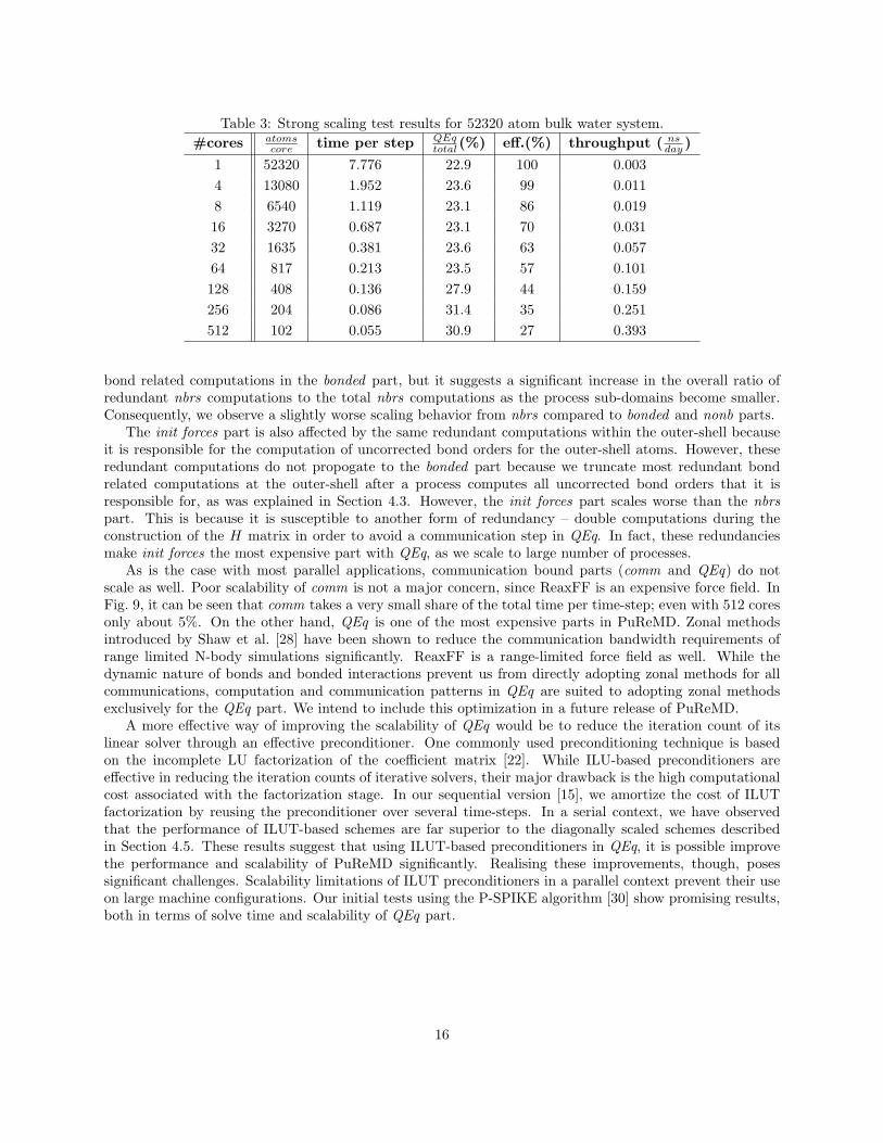
Table 3: Strong scaling test results for 52320 atom bulk water system.#cores atoms
core time per step QEqtotal(%) eff.(%) throughput ( ns
day )
1 52320 7.776 22.9 100 0.0034 13080 1.952 23.6 99 0.0118 6540 1.119 23.1 86 0.01916 3270 0.687 23.1 70 0.03132 1635 0.381 23.6 63 0.05764 817 0.213 23.5 57 0.101128 408 0.136 27.9 44 0.159256 204 0.086 31.4 35 0.251512 102 0.055 30.9 27 0.393
bond related computations in the bonded part, but it suggests a significant increase in the overall ratio ofredundant nbrs computations to the total nbrs computations as the process sub-domains become smaller.Consequently, we observe a slightly worse scaling behavior from nbrs compared to bonded and nonb parts.
The init forces part is also affected by the same redundant computations within the outer-shell becauseit is responsible for the computation of uncorrected bond orders for the outer-shell atoms. However, theseredundant computations do not propogate to the bonded part because we truncate most redundant bondrelated computations at the outer-shell after a process computes all uncorrected bond orders that it isresponsible for, as was explained in Section 4.3. However, the init forces part scales worse than the nbrspart. This is because it is susceptible to another form of redundancy – double computations during theconstruction of the H matrix in order to avoid a communication step in QEq. In fact, these redundanciesmake init forces the most expensive part with QEq, as we scale to large number of processes.
As is the case with most parallel applications, communication bound parts (comm and QEq) do notscale as well. Poor scalability of comm is not a major concern, since ReaxFF is an expensive force field. InFig. 9, it can be seen that comm takes a very small share of the total time per time-step; even with 512 coresonly about 5%. On the other hand, QEq is one of the most expensive parts in PuReMD. Zonal methodsintroduced by Shaw et al. [28] have been shown to reduce the communication bandwidth requirements ofrange limited N-body simulations significantly. ReaxFF is a range-limited force field as well. While thedynamic nature of bonds and bonded interactions prevent us from directly adopting zonal methods for allcommunications, computation and communication patterns in QEq are suited to adopting zonal methodsexclusively for the QEq part. We intend to include this optimization in a future release of PuReMD.
A more effective way of improving the scalability of QEq would be to reduce the iteration count of itslinear solver through an effective preconditioner. One commonly used preconditioning technique is basedon the incomplete LU factorization of the coefficient matrix [22]. While ILU-based preconditioners areeffective in reducing the iteration counts of iterative solvers, their major drawback is the high computationalcost associated with the factorization stage. In our sequential version [15], we amortize the cost of ILUTfactorization by reusing the preconditioner over several time-steps. In a serial context, we have observedthat the performance of ILUT-based schemes are far superior to the diagonally scaled schemes describedin Section 4.5. These results suggest that using ILUT-based preconditioners in QEq, it is possible improvethe performance and scalability of PuReMD significantly. Realising these improvements, though, posessignificant challenges. Scalability limitations of ILUT preconditioners in a parallel context prevent their useon large machine configurations. Our initial tests using the P-SPIKE algorithm [30] show promising results,both in terms of solve time and scalability of QEq part.
16

0
1
2
3
4
5
1 10 100 1000 0
10
20
30
40
50
60
time
per s
tep
(s)
coun
t
num cores
PuReMDPuReMD QEq iterationsPuReMD total matvecs
Lammps-ReaxLammps-Reax QEq iters & matvecs
Figure 10: Comparison of PuReMD and LAMMPS codes under weak scaling. The left y-axis shows the pertime-step running times for both codes. The right y-axis is the average matrix-vector multiplication andlinear solver iteration counts per step. Since LAMMPS always does a single matrix-vector multiplicationper iteration, we show its iteration and matrix-vector multiplication counts in a single curve.
5.3 Comparison with LAMMPS
In this section, we present the performance comparison of our code with the only other publicly availableparallel ReaxFF implementation, ReaxFF package in LAMMPS. We repeat the same weak scaling andstrong scaling tests described above using the LAMMPS code and provide comparisons. Both codes havebeen compiled using the the same compilers (Intel C/C++ compilers), compiler flags (-O3 -funroll-loops-fstrict-aliasing), and MPI library (MVAPICH2) on the Hera cluster. Neither code has been tuned to thespecific architecture of the machine. It is possible that the performance of these codes may be furtherimproved through platform-specific optimizations.
Fig. 10 shows the comparison of both codes under the weak scaling test. On a single core, PuReMD isabout five times faster than LAMMPS. However, LAMMPS code shows a surprising drop in the per time-steprunning time while going from 1 to 4 and then 8 cores. Despite the drop, PuReMD is still about four timesfaster than LAMMPS. Taking the 16 cores runtime as basis, as we did in Section 5.1, LAMMPS achieves aweak scaling efficiency which is very close to that of PuReMD (76% vs 78%, respectively). The main reasonbehind the increase in LAMMPS’s time per time-step is the increasing number of iterations required by itscharge equilibration solver as the system size increases. By using a different mathematical formulation forsolving the charge equilibration problem and applying key optimizations described in Section 4.5, we areable to maintain constant matrix-vector multiplication and PCG iteration counts at a much lower level.
Fig. 11 shows the results of our strong scaling comparisons. We could not run the 52320 bulk watersimulation with LAMMPS code using fewer than 8 cores due to memory limitations. At 8 cores, PuReMDis about three times faster than LAMMPS, and we are able to maintain this ratio all the way through 512cores.
Finally, we would like to note that PuReMD has been designed and developed to be modular andextensible, like LAMMPS. Consequently, it is quite easy to make improvements and modifications on it.Modifying the PuReMD code to work with other bond-order potentials would primarily involve modifyingthe force computation routines.
17

0.0001
0.001
0.01
0.1
1
1 10 100
time
per a
tom
per
ste
p (m
s)
num cores
PuReMDPuReMD ideal scaling
Lammps-ReaxLammps-Reax ideal scaling
Figure 11: Comparison of PuReMD and LAMMPS codes under strong scaling. Gray lines indicate the idealscaling curves for both codes.
5.4 Memory Usage
Another important aspect of PuReMD is its small memory footprint and its ability to adapt to the memoryneeds of the system to be simulated. We were unable to measure the precise memory footprint of PuReMDon the Hera cluster. However, our tests have shown that PuReMD is able to simulate a 296,960 atom PETNsystem on a single processor using an estimated memory of 15GB. To the best of our knowledge, PuReMDis the only ReaxFF implementation that can simulate such large systems with great ease – i.e. withoutrequiring any tuning of compilation and runtime parameters.
It is important to note that in spite of the critical performance analysis presented in this section, PuReMDachieves high parallel efficiency under typical weak-scaling workloads (over 78% at over 3K processing codes)with a small memory footprint. It does so at excellent per-step per-particle simulation time (which rendersachieving this high parallel efficiency more difficult) and yields perfect agreement with the ReaxFF modelpotentials. To this end, PuReMD provides a unique simulation capability.
6 Concluding Remarks
In this paper, we have presented an efficient and scalable parallel implementation for ReaxFF in C usingMPI. Our open-source implementation is shown to be (i) 3-5 times faster compared to other implementations,(ii) has a significantly smaller memory footprint, and (iii) has been demonstrated to scale to more than 3Kcomputational cores under weak-scaling scenarios, yielding over 78% efficiency. Its modular and extensibledesign makes further improvements and enhancements very easy.
PuReMD’s accuracy has been verified against the original ReaxFF code by comparing the energy andforces due to every single interaction in the Reax formulation under many diverse simulation scenarios. Wehave compared the net forces on individual atoms and verified that any differences are within expectednumerical deviations. In addition to the systems used in this paper, PuReMD has been used by otherresearch groups to study such diverse systems as strain relaxation in Si-Ge nanorods, water-silica systemsunder pressure, and Ti-silica systems under impact stress.
18

Acknowledgment
The authors would like to thank Adri van Duin for significant help through all aspects of software develop-ment, Aidan Thompson and Steve Plimpton for various discussions on parallel ReaxFF implementation andtheir comments on an initial version of this paper. The authors would like to acknowledge grants from theDepartment of Energy and the National Science Foundation, and computational resources at the Departmentof Energy/LLNL.
References
[1] T.A. Halgren, W. Damm, Polarizable Force Fields, Current Opinion in Structural Biology, 11, 236-242,2001.
[2] J.E. Davis, G.L. Warren, S. Patel, Revised Charge Equilibration Potential for Liquid Alkanes, J PhysChem B, 112, 8298-8310, 2008.
[3] D.W. Brenner, Empirical potential for hydrocarbons for use in simulating the chemical vapor depositionof diamond films, Phys Rev B, 42, 9458-9471, 1990.
[4] D.W. Brenner, O.A. Shenderova, J.A. Harrison, S.J. Stuart, S.B. Sinnott, A second-generation reactiveempirical bond order (REBO) potential energy expression for hydrocarbons, J Phys Condens Matter, 14,783802, 2002.
[5] S.J. Stuart, A.B. Tutein, J.A. Harrison, A reactive potential for hydrocarbons with intermolecular inter-actions, J Chem Phys, 112, 6472, 2000.
[6] A.C.T. van Duin, S. Dasgupta, F. Lorant, W.A. Goddard III, ReaxFF: A Reactive Force Field forHydrocarbons, J Phys Chem A, 105, 9396-9409, 2001.
[7] K.D. Nielson, A.C.T. van Duin, J. Oxgaard, W-Q. Deng, W.A. Goddard III, Development of the ReaxFFreactive force field for describing transition metal catalyzed reactions, with application to the initial stagesof the catalytic formation of carbon nanotubes, J Phys Chem A, 109, 493-499, 2005.
[8] K. Chenoweth, S. Cheung, A.C.T. van Duin, W.A. Goddard III, E.M. Kober, Simulations on the ThermalDecomposition of a Poly(dimethylsiloxane) Polymer Using the ReaxFF Reactive Force Field, J Am ChemSoc, 127, 7192-7202, 2005.
[9] M.J. Buehler, Hierarchical chemo-nanomechanics of proteins: Entropic elasticity, protein unfolding andmolecular fracture, J Mech Material Struct, 2(6),1019-1057, 2007.
[10] A. Thompson, H. Cho. (2010, Apr.) LAMMPS/ReaxFF potential. [Online]. Available: http://lammps.sandia.gov/doc/pair\ reax.html
[11] R. Barrett, M. Berry, T.F. Chan, J. Demmel, J. Donato, J. Dongarra, V. Eijkhout, R. Pozo, C. Romine,H. Van der Vorst, Templates for the Solution of Linear Systems: Building Blocks for Iterative Methods,2nd Edition, SIAM, 1994.
[12] S.J. Plimpton, Fast Parallel Algorithms for Short-Range Molecular Dynamics, J Comp Phys, 117, 1-19,1995.
[13] S.J. Plimpton, P. Crozier, A. Thompson. (2010, Apr.) LAMMPS Molecular Dynamics Simulator. [On-line]. Available: http://lammps.sandia.gov/index.html
[14] A. Nakano, R.K. Kalia, K. Nomura, A. Sharma, P. Vashishta, F. Shimojo, A.C.T. van Duin, W.A. God-dard, R. Biswas, D. Srivastava, L.H. Yang, De Novo Ultrascale Atomistic Simulations On High-End, IntlJ High Perf Comp Apps, 22(1), 113-128, 2008.
19

[15] H.M. Aktulga, S. Pandit, A.C.T. van Duin, A. Grama Reactive Molecular Dynamics: Numerical Methodsand Algorithmic Techniques in submission, available as a Purdue University Technical Report.
[16] Y. Park, H.M. Aktulga, A.Y. Grama, A. Strachan, Strain relaxation in Si/Ge/Si nanoscale bars fromMD simulations, J Appl Phys, 106, 034304, 2009.
[17] J.C. Fogarty, H.M. Aktulga, A.C.T. van Duin, A.Y. Grama, S.A. Pandit, A Reactive Simulation of theSilica-Water Interface, J Chem Phys, in press.
[18] A.K. Rappe, W.A. Goddard III, Charge equilibration for molecular dynamics simulations, J Phys Chem,95, 33583363, 1991.
[19] Aiichiro Nakano, Parallel multilevel preconditioned conjugate-gradient approach to variable-chargemolecular dynamics, Comp Phys Comm, 104, 59-69, 1997.
[20] J.R. Shewchuk, An introduction to the conjugate gradient method without the agonizing pain, School ofComputer Science, Carnegie Mellon University, Tech Report, August, 1994.
[21] Y. Saad, M.H. Schultz, GMRES: A generalized minimal residual method for solving nonsymmetric linearsystems, SIAM J Sci Stat Comput,7, 856-869, 1986.
[22] Y. Saad, Iterative methods for sparse linear systems, 2nd Edition, SIAM, 2003.
[23] B.G. Fitch, R.S. Germain, M. Mendell, J. Pitera, M. Pitman, A. Rayshubskiy, Y. Sham, F. Suits,W. Swope, T.J C. Ward, Y. Zhestkov, R. Zhou, Blue Matter, an application framework for molecularsimulation on Blue Gene, J Parallel Distributed Comput, 63, 759-773, 2003.
[24] J.C. Phillips, R. Braun, W. Wang, J. Gumbart, E. Tajkhorshid, E. Villa, C. Chipot, R.D. Skeel, L. Kal,K. Schulten, Scalable Molecular Dynamics with NAMD, J Comput Chem, 26(16), 17811802, 2005.
[25] B. Hess, C. Kutzner, D. van der Spoel, E. Lindahl, GROMACS 4: Algorithms for Highly Efficient,Load-Balanced, and Scalable Molecular Simulation J Chem Theory Comput, 4(3), 435447, 2008.
[26] K.J. Bowers, E. Chow, H. Xu, R.O. Dror, M.P. Eastwood, B.A. Gregersen, J.L. Klepeis, I. Kolossvry,M.A. Moraes, F.D. Sacerdoti, J.K. Salmon, Y. Shan, D.E. Shaw, Scalable Algorithms for MolecularDynamics Simulations on Commodity Clusters, SC06, Tampa, Florida, Nov 1117, 2006.
[27] D.E. Shaw, M.M. Deneroff, R.O. Dror, J.S. Kuskin, R.H. Larson, J.K. Salmon, C. Young, B. Batson,K.J. Bowers, J.C. Chao, M.P. Eastwood, J. Gagliardo, J.P. Grossman, C.R. Ho, D.J. Ierardi, I. Kolossvry,J.L. Klepeis, T. Layman, C. McLeavey, M.A. Moraes, R. Mueller, E.C. Priest, Y. Shan, J. Spengler,M. Theobald, B. Towles, S.C. Wang, Anton: A Special-Purpose Machine for Molecular Dynamics Sim-ulation, ISCA’07, San Diego, California, Jun 913, 2007.
[28] K.J. Bowers, R.O. Dror, D.E. Shaw, Zonal methods for the parallel execution of range-limited N-bodysimulations, J Comp Phys, 221, 303329, 2007.
[29] -. (2009, Aug.) Linux Clusters Overview. [Online]. Available: https://computing.llnl.gov/tutorials/linux\ clusters/\#OpteronMemoryConsiderations
[30] M. Manguoglu, A. Sameh, O. Schenk, PSPIKE: A Parallel Hybrid Sparse Linear System Solver, LecNotes Comp Sci, 5704, 797-808, 2009.
20