parallel computing as a vehicle for engineering design of complex functional surfaces
TRANSCRIPT

Advances in Engineering Software 42 (2011) 228–236
Contents lists available at ScienceDirect
Advances in Engineering Software
journal homepage: www.elsevier .com/locate /advengsoft
Parallel computing as a vehicle for engineering design of complexfunctional surfaces
Y.C. Lee a, D.R. Emerson b, P.H. Gaskell a,⇑, X.J. Gu b, H.M. Thompson a
a School of Mechanical Engineering, University of Leeds, Yorkshire LS2 9JT, United Kingdomb Department of Computational Science and Engineering, STFC Daresbury Laboratory, Warrington WA4 4AD, United Kingdom
a r t i c l e i n f o
Article history:Available online 8 December 2010
Keywords:MultigridAdaptive time-steppingParallelisationThin film flowLubrication approximationTopography
0965-9978/$ - see front matter � 2010 Civil-Comp Ltdoi:10.1016/j.advengsoft.2010.10.004
⇑ Corresponding author.E-mail address: [email protected] (P.H. Gask
a b s t r a c t
Thin liquid film flow over surfaces containing complex multiply connected topography is modelled usinglubrication theory. The resulting time dependent nonlinear coupled set of governing equations for filmthickness and pressure is solved on different parallel computing platforms using a purpose written por-table and scalable parallel multigrid algorithm in order to achieve the fine-scale resolution required toguarantee mesh independent solutions. The robustness of the approach is demonstrated via the solutionof three problems: one to establish the convergence characteristics viz. the partitioning and messagepassing strategies adopted, taking flow over a well-defined trench topography as a benchmark againstexisting experimental and corresponding numerical predictions; two, flow through a sparsely distributedset of occlusions with computations performed on different parallel architectures; three, free-surface pla-narisation with respect to flow over complex topography – the first an engineered functional substrate,the second a naturally occurring surface.
� 2010 Civil-Comp Ltd and Elsevier Ltd. All rights reserved.
1. Introduction
The controlled deposition of thin liquid films, involving a bal-ance between viscous and surface tension forces, is encounteredrecurringly in the case of numerous engineered and naturallyoccurring surfaces which have in common that they feature eitherwell-defined or randomly distributed micro- and nano-scaletopography. Examples from nature include the control of diseasein plants [1] and in the redistribution of the liquid linings of respi-ratory systems [2]. Ones typically encountered during manufactur-ing include, the direct patterning of functional layers as part ofmicrochip [3] and micro-electromechanical (MEMS) device [4] pro-duction, with the demand/requirement for greater miniaturisationimposing the need to meet ever-stricter tolerances. Of particularinterest from a practical standpoint is the severity of the free-sur-face disturbance that results and persists, in some instances, overlength-scales several orders of magnitude larger than the size ofthe topographical feature(s) encountered [5].
The presence/occurrence of topography on real surfaces israrely localised and therefore offers a serious challenge to anyonewishing to accurately predict the associated three-dimensionalthin film flow over it. Ideally, one would like to solve the governingunsteady Navier–Stokes equations in full in order to explore both
d and Elsevier Ltd. All rights reser
ell).
the internal flow structure within [6,7] as well as the evolutionof the bounding free-surface; however, the computational resourcerequired is currently prohibitive.
If predicting the free-surface shape is of prime interest, as it of-ten is in terms of coverage and degree of planarity, the assumptionof Stokes flow renders the problem more tractable, see for example[8,9] who used a boundary element method to solve the problem offilm flow over a small particle adjacent to a flat wall. Or, as utilisedin the present investigation, the problem can be simplified further.This is achieved by noting that for thin films the ratio of the undis-turbed asymptotic film thickness to that of the characteristiclength-scale of the flow is small, expanding the Stokes equationsin terms of this small parameter and retaining the leading orderterms only.
Not surprisingly, the above lubrication approximation, as it iscommonly referred to, has proved popular, with the associatedequation(s) solved using a variety of numerical methods, withsemi-implicit alternating direction time-splitting schemes [10,11]enjoying wide usage. The argument for employing the latter is thatthey combine some of the stability properties of implicit schemeswith the cost efficiencies of explicit ones, but when fine meshesare required to ensure mesh-independent solutions the choice oftime-step is severely restricted. Alternatively, [12] have shownthat the adoption of a fully-implicit multigrid approach results ina more robust numerical algorithm and to vastly improve the rateof convergence at the extremely refined mesh levels required foraccuracy. This is reinforced by [6] who combined a similar
ved.

Fig. 1. Schematics of gravity-driven thin film flow: (a) over a square trench; (b) pasta square occlusion.
Y.C. Lee et al. / Advances in Engineering Software 42 (2011) 228–236 229
multigrid formulation with error-controlled adaptive time-steppingto solve gravity-driven thin film flows over various topographicalfeatures. In addition, a comparison of their predictions with thedetailed experimental data of [5] shows that the lubricationapproximation leads to sufficiently accurate solutions, even incases for which it is not strictly valid. This multigrid methodologyhas subsequently been refined to embody automatic error-controlledadaptive local mesh refinement [13] leading to: (i) further significantimprovements in solution times and the better use of computationalresource without loss of accuracy; (ii) a better understanding ofthin film flow over complex surface patterns [14] and past minuteocclusions [15].
Despite the above multigrid efficiency gains that have beenmade and the free-surface problems that have been solved as a re-sult, the method is compromised when the substrates involved arelarge in extent and/or feature densely populated fine-scale inter-connected topographical features. This paper, therefore, focuseson the development and application of a portable, parallel multi-grid solver, based on lubrication theory, as a vehicle for overcom-ing this restriction by combining the benefits offered from bothmultigridding and parallel computing.
Recent work [16] has shown that a parallel, full approximationstorage (FAS) multigrid approach is capable of solving dropletspreading flows with physically realistic precursor film thicknessesand quantitatively accurate droplet spreading rates. Similarly, [17]implemented such a parallel multigridding approach for the solu-tion of elastohydrodynamic lubrication problems with improvedperformance attained due to parallelisation of the underpinningalgorithm, utilising up to 128 processors for the solution of a prob-lem involving over 270 million nodal points. Parallel multigridsolvers scale well, as reported in [18–20], resulting in a parallelperformance not less than 0.63 over the range of processors usedfor the solution of the different problems considered. While theadvantage offered by parallel multigrid methods are easily com-prehended, there are potential drawbacks embedded within theapproach; in particular, concerning the high communication costsrelative to computational costs when computations are performedon coarse grid levels. However, this can be alleviated in differentways [21] – in the present study, the coarsest grid level is selectedsuch that the cost of communication to computation ratio stayswithin a reasonable range [22].
The problem of interest and associated mathematical modelare described in Section 2. The method of solution is outlined inSection 3, together with an overview of the parallel computing issuesaddressed. A number of thin film flow problems are investigatedand the results obtained, evaluated in terms of accuracy, perfor-mance, flexibility and extensibility on different parallel computingplatforms, are described in Section 4. Conclusions are drawn inSection 5.
2. Problem definition and mathematical description
2.1. Mathematical model
A generic set of governing equations, based on the long wave-length approximation, for thin film flow is derived as follows. Con-sider Fig. 1 which shows schematics of the motion of a thin liquidfilm of thickness, H(X, Y, T), and constant volumetric flow, Q0, perunit width over a flat substrate, inclined at an angle h to thehorizontal containing a single: (a) rectangular trench topographyS(X, Y), of depth S0; (b) rectangular occlusion, S(X, Y) >> H(X, Y, T).
The liquid is assumed Newtonian, incompressible and inertia-less, with constant viscosity, l, density, q, and surface tension, r.Proceeding as in [13] and assuming that � = H0/L0 is small, whereL0 is the characteristic in-plane length scale which is proportionalto the capillary length, Lc, and given by:
L0 ¼ brH0
3qg sin h
� �1=3
and b ¼ L0=Lc; ð1Þ
with H0 = (3lQ0/qgsinh)1/3 defined as the undisturbed fully-developedasymptotic film thickness, and where g is the acceleration due togravity, the governing Navier–Stokes and continuity equations canbe simplified to yield the well known lubrication approximation[23]. Using the following scalings, (x, y) = (X, Y)/L0, h = H/H0,t = U0T/L0, U0 = 3Q0/2H0, s = S/H0 and p = 2P/qg L0sinh, the equationfor film thickness can be written:
@h@t¼ @
@xh3
3@p@x� 2
� �" #þ @
@yh3
3@p@y
� �" #; ð2Þ
with the pressure throughout the film, given by:
p ¼ � 6b3r
2ðhþ sÞ þ 2b
61=3Nðhþ sÞ; ð3Þ
in which the pressure datum is set to zero. N = Ca1/3coth measuresthe influence of the normal component of gravity on the flow profileand Ca ¼ ð9l2Q2
0=8qgr3 sin hÞ1=3 is the capillary number.
230 Y.C. Lee et al. / Advances in Engineering Software 42 (2011) 228–236
2.2. Boundary conditions
The problem is closed by imposing appropriate boundary condi-tions under the usual assumption of no-slip at the surface of thesubstrate and zero tangential stress at the free-surface. Fully devel-oped flow conditions far upstream require:
hðx ¼ 0; yÞ ¼ 1; ð4Þ
while other stream- and span-wise boundaries are imposed byassuming zero flux there such that gradients in h and p are zero.
Additionally, at the interface points between the free-surfaceand a solid occlusion, a static wetting condition is assumed[14,15], such that:
rhw � n ¼ tanp2� hs
� �; ð5Þ
where hw(x, y) denotes the static wetting line around the occlusion,n is the outward pointing unit normal at the occlusion surface andhs the static contact angle there. To preserve volumetric flux, q, azero flux condition:
q ¼ �h3
3ðrp� 2iÞ ¼ 0; where i ¼ ð1; 0Þ ð6Þ
is imposed at the occlusion’s surface.
2.3. Surface patterning
Following [3], the topography depth, s, is defined via arctangentfunctions which enable the side steepness to be controlled easily,thus allowing the flexibility of creating simple primitive shapes[13]. For example, the rectangular topography shown in Fig. 1a,of length lt = LT/L0, width wt = WT/L0 and height, s0 = S0/H0, centredat point (xt, yt), is specified by defining:
sðx; yÞ ¼ s0
b0tan�1 �ax � lt=2
clt
� �þ tan�1 ax � lt=2
clt
� �� �
� tan�1 �ay �wt=2cwt
� �þ tan�1 ay �wt=2
cwt
� �� �; ð7Þ
where c is an adjustable steepness parameter, A = wt/lt is the aspectratio,
b0 ¼ 4 tan�1 12c
� �tan�1 A
2c
� �; ð8Þ
and local topography coordinates in the x and y directions are givenby:
ax ¼ xt � x; ð9Þay ¼ yt � y: ð10Þ
Eq. (7) can be used to specify most simple primitive topographysuch as elliptic or lozenge shapes by modifying ax and ay appropri-ately. It is then relatively straightforward to add/subtract theseprimitives to create complex topographical patterns that representfunctional engineering substrates [14].
In the case of complex inter-connected topography pertainingto naturally occurring surfaces, the complex topological profilesin s are obtained by digitally mapping actual surface heights. Themapped profiles are recorded via a simple image terrain elevationalgorithm; assuming that the density of the material considered isthin and uniform, the vertical heights are calculated by measuringthe intensity of the monochromatic brightness of the image.
For problems involving occlusions, complex surface blockagesare constructed from the union and/or exclusion of basic primitiveshapes; for example simple geometric forms were used to generatethe occlusion pattern investigated in Section 4.
3. Numerical method
3.1. Spatial discretisation
The lubrication Eqs. (2) and (3) are discretised with the sameuniform mesh spacing, D, in the x and y directions, using finite dif-ferences which leads to the following second-order accurate spa-tial analogues for h and p:
@hi;j
@t¼ 1
D2
h3
3
�����iþ1
2;j
ðpiþ1;j � pi;jÞ
24
� h3
3
�����i�1
2;j
ðpi;j � pi�1;jÞ þh3
3
�����i;jþ1
2
ðpi;jþ1 � pi;jÞ �h3
3
�����i;j�1
2
ðpi;j � pi;j�1Þ
35
� 2D
h3
3
�����iþ1
2;j
� h3
3
�����i�1
2;j
0@
1A; ð11Þ
pi;j þ6
b3D2 ðhiþ1;j þ siþ1;jÞ þ ðhi�1;j þ si�1;jÞ þ ðhi;jþ1 þ si;jþ1Þ
þðhi;j�1 þ si;j�1Þ � 4ðhi;j þ si;jÞ� 2
ffiffiffi63p
Nbðhi;j þ si;jÞ ¼ 0; ð12Þ
at each mesh point, (i, j), in the computational domain. The terms,h3
3
���i�1
2;j; h3
3
���i;j�1
2
are the pre-factors obtained from linear interpolation
between neighbouring points.
3.2. Adaptive temporal discretisation
Time integration is performed using the standard, second-orderaccurate Crank–Nicholson method to approximate the time-derivative of Eq. (11). Rewriting the right-hand-side as a functionF(hi,j, pi,j, hi±1,j, pi±1,j, hi,j±1, pi,j±1) leads to an equation for h of theform:
hnþ1i;j �
Dtnþ1
2Fðhnþ1
i;j ;pnþ1i;j ; hnþ1
i�1;j;pnþ1i�1;j; h
nþ1i;j�1;p
nþ1i;j�1Þ
¼ hni;j þ
Dtnþ1
2Fðhn
i;j; pni;j; h
ni�1;j;p
ni�1;j; h
ni;j�1;p
ni;j�1Þ; ð13Þ
for which Dtn+1 = tn+1 � tn, and the right-hand-side is given in termsof known values at the end of the nth time step, t = tn.
Automatic adaptive time-stepping employs a temporal errorcontrol algorithm using predictor–corrector stages, as reported in[24]. It provides an efficient alternative to existing schemes [25]by using time-stepping based on local error estimates that areimplicit and second-order accurate, obtained from the differencebetween the current solution and a predicted one, to increase ordecrease the time step in a controlled manner whilst concurrentlyminimising the computational expense associated with repeatedtime step failure.
3.3. Multigrid strategy
In line with the multigrid algorithm employed in [13], a se-quence of progressively finer grids (Gk: k = 0,1, . . . ,K) is definedwith uniform mesh spacing Dk. Each grid level, Gk, hasnk = 2k+c+1 + 1 nodes in each co-ordinate direction where c is a con-stant defining the resolution at the coarsest grid level, such thatmesh size, Dk = 2�(k+c+1).
The associated time dependent, nonlinear, coupled set of gov-erning lubrication Eqs. (2) and (3) is solved using a full approxima-tion storage (FAS) multigrid scheme. Computations are performedusing a Full Multigrid W(2, 2) cycle.
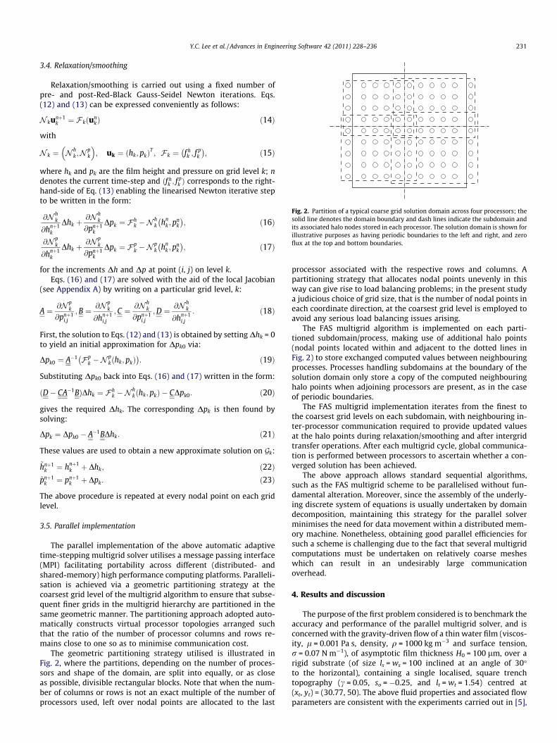
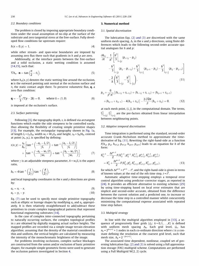
Fig. 2. Partition of a typical coarse grid solution domain across four processors; thesolid line denotes the domain boundary and dash lines indicate the subdomain andits associated halo nodes stored in each processor. The solution domain is shown forillustrative purposes as having periodic boundaries to the left and right, and zeroflux at the top and bottom boundaries.
Y.C. Lee et al. / Advances in Engineering Software 42 (2011) 228–236 231
3.4. Relaxation/smoothing
Relaxation/smoothing is carried out using a fixed number ofpre- and post-Red-Black Gauss-Seidel Newton iterations. Eqs.(12) and (13) can be expressed conveniently as follows:
N kunþ1k ¼ F kðun
kÞ ð14Þ
with
N k ¼ N hk ;N
pk
� �; uk ¼ ðhk;pkÞ
T; F k ¼ f h
k ; fpk
� ; ð15Þ
where hk and pk are the film height and pressure on grid level k; ndenotes the current time-step and ðf h
k ; fpk Þ corresponds to the right-
hand-side of Eq. (13) enabling the linearised Newton iterative stepto be written in the form:
@N hk
@hnþ1k
Dhk þ@N h
k
@pnþ1k
Dpk ¼ F hk �N
hk hn
k ;pnk
� ; ð16Þ
@N pk
@hnþ1k
Dhk þ@N p
k
@pnþ1k
Dpk ¼ Fpk �N
pk hn
k ;pnk
� ; ð17Þ
for the increments Dh and Dp at point (i, j) on level k.Eqs. (16) and (17) are solved with the aid of the local Jacobian
(see Appendix A) by writing on a particular grid level, k:
A ¼ @N pk
@pnþ1i;j
;B ¼ @N pk
@hnþ1i;j
; C ¼ @N hk
@pnþ1i;j
;D ¼ @N hk
@hnþ1i;j
: ð18Þ
First, the solution to Eqs. (12) and (13) is obtained by setting Dhk = 0to yield an initial approximation for Dpk0 via:
Dpk0 ¼ A�1 F pk �N
pkðhk;pkÞ
� : ð19Þ
Substituting Dpk0 back into Eqs. (16) and (17) written in the form:
ðD� CA�1BÞDhk ¼ F hk �N
hkðhk;pkÞ � CDpk0: ð20Þ
gives the required Dhk. The corresponding Dpk is then found bysolving:
Dpk ¼ Dpk0 � A�1BDhk: ð21Þ
These values are used to obtain a new approximate solution on Gk:
~hnþ1k ¼ hnþ1
k þ Dhk; ð22Þ~pnþ1
k ¼ pnþ1k þ Dpk: ð23Þ
The above procedure is repeated at every nodal point on each gridlevel.
3.5. Parallel implementation
The parallel implementation of the above automatic adaptivetime-stepping multigrid solver utilises a message passing interface(MPI) facilitating portability across different (distributed- andshared-memory) high performance computing platforms. Paralleli-sation is achieved via a geometric partitioning strategy at thecoarsest grid level of the multigrid algorithm to ensure that subse-quent finer grids in the multigrid hierarchy are partitioned in thesame geometric manner. The partitioning approach adopted auto-matically constructs virtual processor topologies arranged suchthat the ratio of the number of processor columns and rows re-mains close to one so as to minimise communication cost.
The geometric partitioning strategy utilised is illustrated inFig. 2, where the partitions, depending on the number of proces-sors and shape of the domain, are split into equally, or as closeas possible, divisible rectangular blocks. Note that when the num-ber of columns or rows is not an exact multiple of the number ofprocessors used, left over nodal points are allocated to the last
processor associated with the respective rows and columns. Apartitioning strategy that allocates nodal points unevenly in thisway can give rise to load balancing problems; in the present studya judicious choice of grid size, that is the number of nodal points ineach coordinate direction, at the coarsest grid level is employed toavoid any serious load balancing issues arising.
The FAS multigrid algorithm is implemented on each parti-tioned subdomain/process, making use of additional halo points(nodal points located within and adjacent to the dotted lines inFig. 2) to store exchanged computed values between neighbouringprocesses. Processes handling subdomains at the boundary of thesolution domain only store a copy of the computed neighbouringhalo points when adjoining processors are present, as in the caseof periodic boundaries.
The FAS multigrid implementation iterates from the finest tothe coarsest grid levels on each subdomain, with neighbouring in-ter-processor communication required to provide updated valuesat the halo points during relaxation/smoothing and after intergridtransfer operations. After each multigrid cycle, global communica-tion is performed between processors to ascertain whether a con-verged solution has been achieved.
The above approach allows standard sequential algorithms,such as the FAS multigrid scheme to be parallelised without fun-damental alteration. Moreover, since the assembly of the underly-ing discrete system of equations is usually undertaken by domaindecomposition, maintaining this strategy for the parallel solverminimises the need for data movement within a distributed mem-ory machine. Nonetheless, obtaining good parallel efficiencies forsuch a scheme is challenging due to the fact that several multigridcomputations must be undertaken on relatively coarse mesheswhich can result in an undesirably large communicationoverhead.
4. Results and discussion
The purpose of the first problem considered is to benchmark theaccuracy and performance of the parallel multigrid solver, and isconcerned with the gravity-driven flow of a thin water film (viscos-ity, l = 0.001 Pa s, density, q = 1000 kg m�3 and surface tension,r = 0.07 N m�1), of asymptotic film thickness H0 = 100 lm, over arigid substrate (of size ls = ws = 100 inclined at an angle of 30�to the horizontal), containing a single localised, square trenchtopography (c = 0.05, so = �0.25, and lt = wt = 1.54) centred at(xt, yt) = (30.77, 50). The above fluid properties and associated flowparameters are consistent with the experiments carried out in [5],
232 Y.C. Lee et al. / Advances in Engineering Software 42 (2011) 228–236
enabling direct comparison with the same and with complementarynumerical predictions obtained using a serial multigrid algorithm[13] employing automatic mesh adaption. The values for Lc = L0
and N are 0.78 mm and 0.12, respectively; the latter indicatingthe normal component of gravity has little effect on the resultantfree-surface shape [6].
The resulting mesh-independent steady-state free-surfacedisturbance, Fig. 3, obtained with a fine mesh containing 1025 �1025 points, reveals the characteristic ‘‘horse-shoe’’ bow-wave and‘‘comet-tail’’ pattern characteristic of thin film flow over trenchtopography [6]. Stream-wise free-surface profiles at different span-wise cross-sectional locations, as depicted in Fig. 4, compare thoseobtained with the current parallel multigrid solver against alterna-tive numerical predictions [13] and ones found experimentally [5]for the same flow conditions. The predicted profiles are found to beidentical (to within round-off error) in all cases and in very goodagreement with their experimental counterparts, the latter havinga reported 2% rms error.
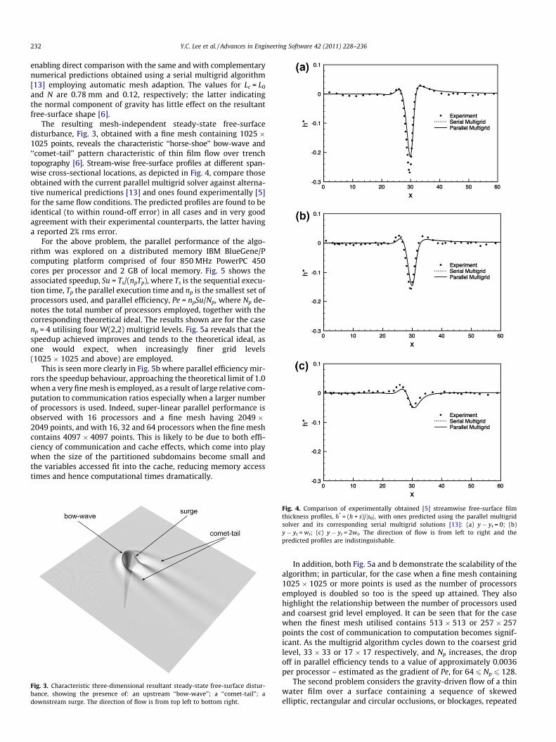
For the above problem, the parallel performance of the algo-rithm was explored on a distributed memory IBM BlueGene/Pcomputing platform comprised of four 850 MHz PowerPC 450cores per processor and 2 GB of local memory. Fig. 5 shows theassociated speedup, Su = Ts/(npTp), where Ts is the sequential execu-tion time, Tp the parallel execution time and np is the smallest set ofprocessors used, and parallel efficiency, Pe = npSu/Np, where Np de-notes the total number of processors employed, together with thecorresponding theoretical ideal. The results shown are for the casenp = 4 utilising four W(2,2) multigrid levels. Fig. 5a reveals that thespeedup achieved improves and tends to the theoretical ideal, asone would expect, when increasingly finer grid levels(1025 � 1025 and above) are employed.
This is seen more clearly in Fig. 5b where parallel efficiency mir-rors the speedup behaviour, approaching the theoretical limit of 1.0when a very fine mesh is employed, as a result of large relative com-putation to communication ratios especially when a larger numberof processors is used. Indeed, super-linear parallel performance isobserved with 16 processors and a fine mesh having 2049 �2049 points, and with 16, 32 and 64 processors when the fine meshcontains 4097 � 4097 points. This is likely to be due to both effi-ciency of communication and cache effects, which come into playwhen the size of the partitioned subdomains become small andthe variables accessed fit into the cache, reducing memory accesstimes and hence computational times dramatically.
Fig. 3. Characteristic three-dimensional resultant steady-state free-surface distur-bance, showing the presence of: an upstream ‘‘bow-wave’’; a ‘‘comet-tail’’; adownstream surge. The direction of flow is from top left to bottom right.
Fig. 4. Comparison of experimentally obtained [5] streamwise free-surface filmthickness profiles, h* = (h + s)/js0j, with ones predicted using the parallel multigridsolver and its corresponding serial multigrid solutions [13]: (a) y � yt = 0; (b)y � yt = wt; (c) y � yt = 2wt. The direction of flow is from left to right and thepredicted profiles are indistinguishable.
In addition, both Fig. 5a and b demonstrate the scalability of thealgorithm; in particular, for the case when a fine mesh containing1025 � 1025 or more points is used as the number of processorsemployed is doubled so too is the speed up attained. They alsohighlight the relationship between the number of processors usedand coarsest grid level employed. It can be seen that for the casewhen the finest mesh utilised contains 513 � 513 or 257 � 257points the cost of communication to computation becomes signif-icant. As the multigrid algorithm cycles down to the coarsest gridlevel, 33 � 33 or 17 � 17 respectively, and Np increases, the dropoff in parallel efficiency tends to a value of approximately 0.0036per processor – estimated as the gradient of Pe, for 64 6 Np 6 128.
The second problem considers the gravity-driven flow of a thinwater film over a surface containing a sequence of skewedelliptic, rectangular and circular occlusions, or blockages, repeated
(a)
(b)
Fig. 5. Performance of the parallel multigrid solver: (a) relative speedup; (b)parallel efficiency. Comparison is drawn with the theoretical result that might beexpected from using five different finest mesh densities, utilising four multigridlevels.
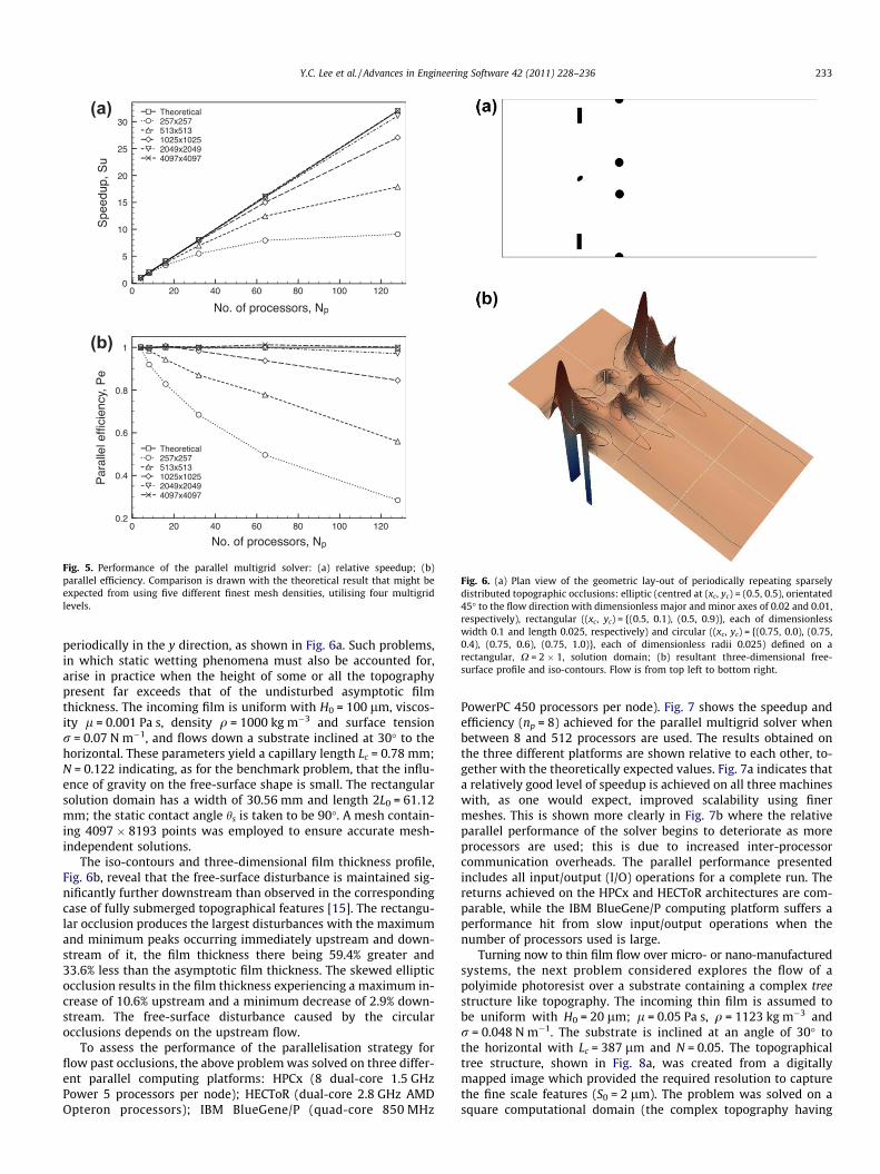
Fig. 6. (a) Plan view of the geometric lay-out of periodically repeating sparselydistributed topographic occlusions: elliptic (centred at (xc, yc) = (0.5, 0.5), orientated45� to the flow direction with dimensionless major and minor axes of 0.02 and 0.01,respectively), rectangular ((xc, yc) = {(0.5, 0.1), (0.5, 0.9)}, each of dimensionlesswidth 0.1 and length 0.025, respectively) and circular ((xc, yc) = {(0.75, 0.0), (0.75,0.4), (0.75, 0.6), (0.75, 1.0)}, each of dimensionless radii 0.025) defined on arectangular, X = 2 � 1, solution domain; (b) resultant three-dimensional free-surface profile and iso-contours. Flow is from top left to bottom right.
Y.C. Lee et al. / Advances in Engineering Software 42 (2011) 228–236 233
periodically in the y direction, as shown in Fig. 6a. Such problems,in which static wetting phenomena must also be accounted for,arise in practice when the height of some or all the topographypresent far exceeds that of the undisturbed asymptotic filmthickness. The incoming film is uniform with H0 = 100 lm, viscos-ity l = 0.001 Pa s, density q = 1000 kg m�3 and surface tensionr = 0.07 N m�1, and flows down a substrate inclined at 30� to thehorizontal. These parameters yield a capillary length Lc = 0.78 mm;N = 0.122 indicating, as for the benchmark problem, that the influ-ence of gravity on the free-surface shape is small. The rectangularsolution domain has a width of 30.56 mm and length 2L0 = 61.12mm; the static contact angle hs is taken to be 90�. A mesh contain-ing 4097 � 8193 points was employed to ensure accurate mesh-independent solutions.
The iso-contours and three-dimensional film thickness profile,Fig. 6b, reveal that the free-surface disturbance is maintained sig-nificantly further downstream than observed in the correspondingcase of fully submerged topographical features [15]. The rectangu-lar occlusion produces the largest disturbances with the maximumand minimum peaks occurring immediately upstream and down-stream of it, the film thickness there being 59.4% greater and33.6% less than the asymptotic film thickness. The skewed ellipticocclusion results in the film thickness experiencing a maximum in-crease of 10.6% upstream and a minimum decrease of 2.9% down-stream. The free-surface disturbance caused by the circularocclusions depends on the upstream flow.
To assess the performance of the parallelisation strategy forflow past occlusions, the above problem was solved on three differ-ent parallel computing platforms: HPCx (8 dual-core 1.5 GHzPower 5 processors per node); HECToR (dual-core 2.8 GHz AMDOpteron processors); IBM BlueGene/P (quad-core 850 MHz
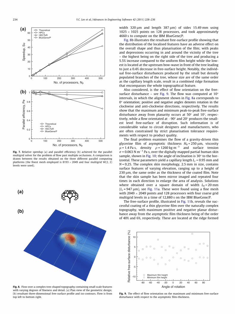
PowerPC 450 processors per node). Fig. 7 shows the speedup andefficiency (np = 8) achieved for the parallel multigrid solver whenbetween 8 and 512 processors are used. The results obtained onthe three different platforms are shown relative to each other, to-gether with the theoretically expected values. Fig. 7a indicates thata relatively good level of speedup is achieved on all three machineswith, as one would expect, improved scalability using finermeshes. This is shown more clearly in Fig. 7b where the relativeparallel performance of the solver begins to deteriorate as moreprocessors are used; this is due to increased inter-processorcommunication overheads. The parallel performance presentedincludes all input/output (I/O) operations for a complete run. Thereturns achieved on the HPCx and HECToR architectures are com-parable, while the IBM BlueGene/P computing platform suffers aperformance hit from slow input/output operations when thenumber of processors used is large.
Turning now to thin film flow over micro- or nano-manufacturedsystems, the next problem considered explores the flow of apolyimide photoresist over a substrate containing a complex treestructure like topography. The incoming thin film is assumed tobe uniform with H0 = 20 lm; l = 0.05 Pa s, q = 1123 kg m�3 andr = 0.048 N m�1. The substrate is inclined at an angle of 30� tothe horizontal with Lc = 387 lm and N = 0.05. The topographicaltree structure, shown in Fig. 8a, was created from a digitallymapped image which provided the required resolution to capturethe fine scale features (S0 = 2 lm). The problem was solved on asquare computational domain (the complex topography having
(a)
(b)
Fig. 7. Relative speedup (a) and parallel efficiency (b) achieved for the parallelmultigrid solver for the problem of flow past multiple occlusions. A comparison isdrawn between the results obtained on the three different parallel computingplatforms (the finest mesh employed is 8193 � 2049 and four multigrid W(2, 2)levels were used).
Fig. 8. Flow over a complex tree-shaped topography containing small scale featureswith varying degrees of fineness and detail. (a) Plan view of the geometric design;(b) resultant three-dimensional free-surface profile and iso-contours. Flow is fromtop left to bottom right.
234 Y.C. Lee et al. / Advances in Engineering Software 42 (2011) 228–236
width 320 lm and length 387 lm) of sides 15.49 mm using1025 � 1025 points on 128 processors, and took approximately4660 s to compute on the IBM BlueGene/P.
Fig. 8b illustrates the resultant free-surface profile showing thatthe distribution of the localised features have an adverse effect onthe overall shape and thus planarisation of the film; with peaksand depressions occurring in and around the vicinity of the tree– the highest being on the right side of the tree and producing a5.5% increase compared to the uniform film height while the low-est is located at the upstream bow-wave in front of the tree leadingto just a 0.4% decrease in free-surface height. Notably, the individ-ual free-surface disturbances produced by the small but denselypopulated branches of the tree, whose size are of the same orderas the capillary length scale, result in a combined ridge formationthat encompasses the whole topographical feature.
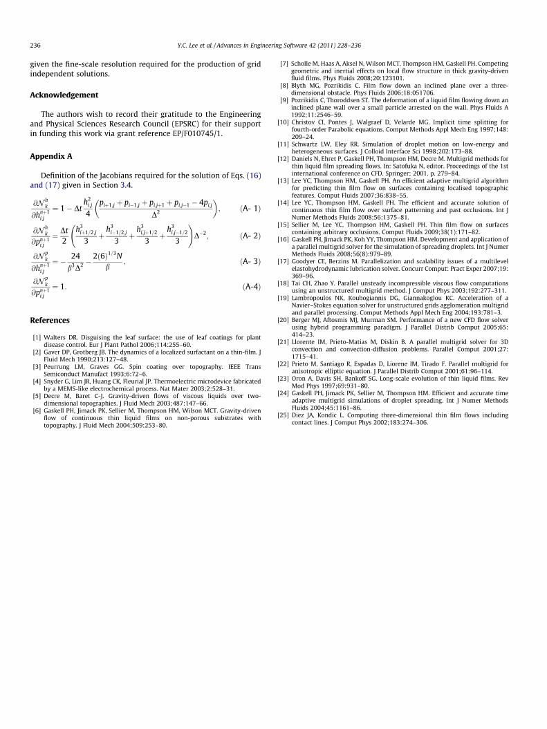
Also considered, is the effect of flow orientation on the free-surface disturbance – see Fig. 9. The flow was computed at 10�intervals, in which the alignment shown in Fig. 8a corresponds to0� orientation; positive and negative angles denotes rotation in theclockwise and anti-clockwise directions, respectively. The resultsshow that the maximum and minimum peak-to-peak free-surfacedisturbance away from planarity occurs at 50� and 10�, respec-tively, while a flow orientated at �90� and 20� produces the small-est level free-surface of disruption. Such information is ofconsiderable value to circuit designers and manufacturers, whoare often constrained by strict planarisation tolerance require-ments with respect to product quality.
The final problem examines the flow of a gravity-driven thinglycerine film of asymptotic thickness H0 = 250 lm, viscosityl = 1.4 Pa s, density q = 1260 kg m�3 and surface tensionr = 0.063 N m�1 Pa s, over the digitally mapped partial human skinsample, shown in Fig. 10; the angle of inclination is 30� to the hor-izontal. These parameters yield a capillary length Lc = 0.95 mm andN = 0.25. The complex skin morphology, 2.5 mm in size, containssurface features of varying elevation, ranging up to a height of230 lm, the same order as the thickness of the coated film. Notethat the skin sample has been mirror imaged and repeated fourtimes in each direction to enlarge the area of analysis. Solutionswhere obtained over a square domain of width L0 = 20 mm(Lc = 947 lm), see Fig. 11a. These were found using a fine meshwith 2049 � 2049 points and 128 processors with four coarse gridmultigrid levels in a time of 12,880 s on the IBM BlueGene/P.
The free-surface profile, illustrated in Fig. 11b, reveals the suc-cessful coating of a thin glycerine film over the naturally complextopography, with maximum positive and negative planar distur-bance away from the asymptotic film thickness being of the orderof 40% and 6%, respectively. These are located at the ridge formed
Fig. 9. The effect of flow orientation on the maximum and minimum free-surfacedisturbance with respect to the asymptotic film-thickness.
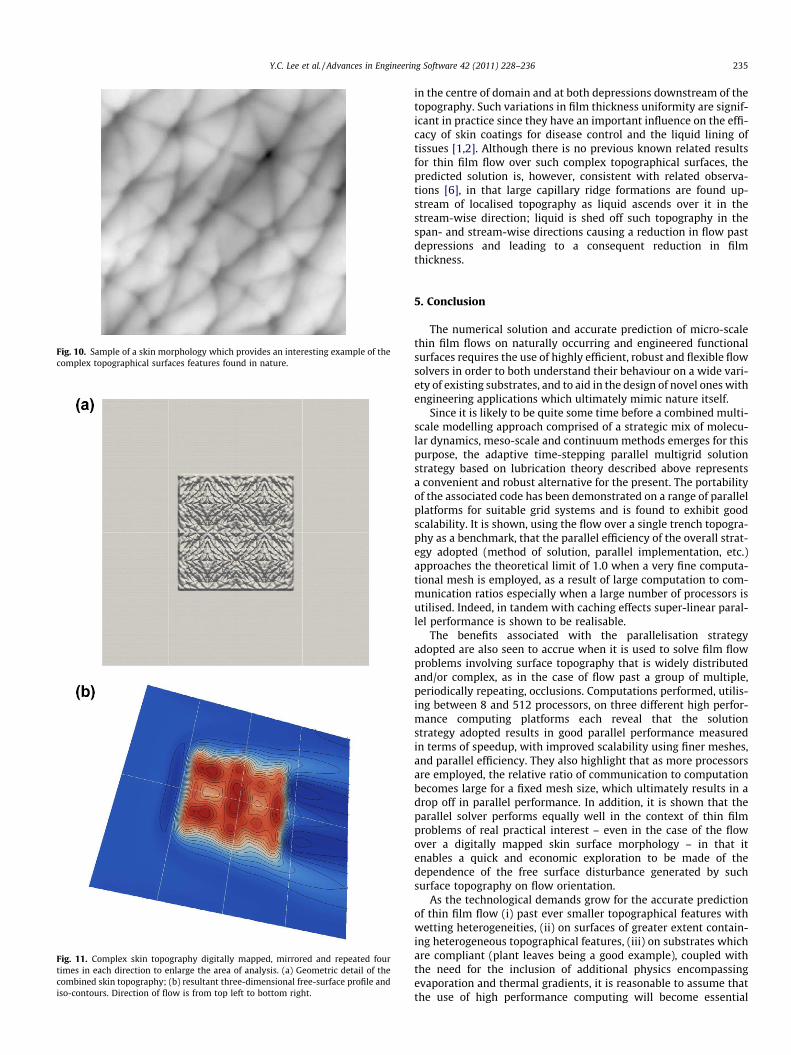
Fig. 10. Sample of a skin morphology which provides an interesting example of thecomplex topographical surfaces features found in nature.
Fig. 11. Complex skin topography digitally mapped, mirrored and repeated fourtimes in each direction to enlarge the area of analysis. (a) Geometric detail of thecombined skin topography; (b) resultant three-dimensional free-surface profile andiso-contours. Direction of flow is from top left to bottom right.
Y.C. Lee et al. / Advances in Engineering Software 42 (2011) 228–236 235
in the centre of domain and at both depressions downstream of thetopography. Such variations in film thickness uniformity are signif-icant in practice since they have an important influence on the effi-cacy of skin coatings for disease control and the liquid lining oftissues [1,2]. Although there is no previous known related resultsfor thin film flow over such complex topographical surfaces, thepredicted solution is, however, consistent with related observa-tions [6], in that large capillary ridge formations are found up-stream of localised topography as liquid ascends over it in thestream-wise direction; liquid is shed off such topography in thespan- and stream-wise directions causing a reduction in flow pastdepressions and leading to a consequent reduction in filmthickness.
5. Conclusion
The numerical solution and accurate prediction of micro-scalethin film flows on naturally occurring and engineered functionalsurfaces requires the use of highly efficient, robust and flexible flowsolvers in order to both understand their behaviour on a wide vari-ety of existing substrates, and to aid in the design of novel ones withengineering applications which ultimately mimic nature itself.
Since it is likely to be quite some time before a combined multi-scale modelling approach comprised of a strategic mix of molecu-lar dynamics, meso-scale and continuum methods emerges for thispurpose, the adaptive time-stepping parallel multigrid solutionstrategy based on lubrication theory described above representsa convenient and robust alternative for the present. The portabilityof the associated code has been demonstrated on a range of parallelplatforms for suitable grid systems and is found to exhibit goodscalability. It is shown, using the flow over a single trench topogra-phy as a benchmark, that the parallel efficiency of the overall strat-egy adopted (method of solution, parallel implementation, etc.)approaches the theoretical limit of 1.0 when a very fine computa-tional mesh is employed, as a result of large computation to com-munication ratios especially when a large number of processors isutilised. Indeed, in tandem with caching effects super-linear paral-lel performance is shown to be realisable.
The benefits associated with the parallelisation strategyadopted are also seen to accrue when it is used to solve film flowproblems involving surface topography that is widely distributedand/or complex, as in the case of flow past a group of multiple,periodically repeating, occlusions. Computations performed, utilis-ing between 8 and 512 processors, on three different high perfor-mance computing platforms each reveal that the solutionstrategy adopted results in good parallel performance measuredin terms of speedup, with improved scalability using finer meshes,and parallel efficiency. They also highlight that as more processorsare employed, the relative ratio of communication to computationbecomes large for a fixed mesh size, which ultimately results in adrop off in parallel performance. In addition, it is shown that theparallel solver performs equally well in the context of thin filmproblems of real practical interest – even in the case of the flowover a digitally mapped skin surface morphology – in that itenables a quick and economic exploration to be made of thedependence of the free surface disturbance generated by suchsurface topography on flow orientation.
As the technological demands grow for the accurate predictionof thin film flow (i) past ever smaller topographical features withwetting heterogeneities, (ii) on surfaces of greater extent contain-ing heterogeneous topographical features, (iii) on substrates whichare compliant (plant leaves being a good example), coupled withthe need for the inclusion of additional physics encompassingevaporation and thermal gradients, it is reasonable to assume thatthe use of high performance computing will become essential
236 Y.C. Lee et al. / Advances in Engineering Software 42 (2011) 228–236
given the fine-scale resolution required for the production of gridindependent solutions.
Acknowledgement
The authors wish to record their gratitude to the Engineeringand Physical Sciences Research Council (EPSRC) for their supportin funding this work via grant reference EP/F010745/1.
Appendix A
Definition of the Jacobians required for the solution of Eqs. (16)and (17) given in Section 3.4.
@N hk
@hnþ1i;j
¼ 1� Dth2
i;j
4piþ1;j þ pi�1;j þ pi;jþ1 þ pi;j�1 � 4pi;j
D2
� �; ðA- 1Þ
@N hk
@pnþ1i;j
¼ Dt2
h3iþ1=2;j
3þ
h3i�1=2;j
3þ
h3i;jþ1=2
3þ
h3i;j�1=2
3
!D�2; ðA- 2Þ
@N pk
@hnþ1i;j
¼ � 24b3D2 �
2ð6Þ1=3Nb
; ðA- 3Þ
@N pk
@pnþ1i;j
¼ 1: ðA-4Þ
References
[1] Walters DR. Disguising the leaf surface: the use of leaf coatings for plantdisease control. Eur J Plant Pathol 2006;114:255–60.
[2] Gaver DP, Grotberg JB. The dynamics of a localized surfactant on a thin-film. JFluid Mech 1990;213:127–48.
[3] Peurrung LM, Graves GG. Spin coating over topography. IEEE TransSemiconduct Manufact 1993;6:72–6.
[4] Snyder G, Lim JR, Huang CK, Fleurial JP. Thermoelectric microdevice fabricatedby a MEMS-like electrochemical process. Nat Mater 2003;2:528–31.
[5] Decre M, Baret C-J. Gravity-driven flows of viscous liquids over two-dimensional topographies. J Fluid Mech 2003;487:147–66.
[6] Gaskell PH, Jimack PK, Sellier M, Thompson HM, Wilson MCT. Gravity-drivenflow of continuous thin liquid films on non-porous substrates withtopography. J Fluid Mech 2004;509:253–80.
[7] Scholle M, Haas A, Aksel N, Wilson MCT, Thompson HM, Gaskell PH. Competinggeometric and inertial effects on local flow structure in thick gravity-drivenfluid films. Phys Fluids 2008;20:123101.
[8] Blyth MG, Pozrikidis C. Film flow down an inclined plane over a three-dimensional obstacle. Phys Fluids 2006;18:051706.
[9] Pozrikidis C, Thoroddsen ST. The deformation of a liquid film flowing down aninclined plane wall over a small particle arrested on the wall. Phys Fluids A1992;11:2546–59.
[10] Christov CI, Pontes J, Walgraef D, Velarde MG. Implicit time splitting forfourth-order Parabolic equations. Comput Methods Appl Mech Eng 1997;148:209–24.
[11] Schwartz LW, Eley RR. Simulation of droplet motion on low-energy andheterogeneous surfaces. J Colloid Interface Sci 1998;202:173–88.
[12] Daniels N, Ehret P, Gaskell PH, Thompson HM, Decre M. Multigrid methods forthin liquid film spreading flows. In: Satofuka N, editor. Proceedings of the 1stinternational conference on CFD. Springer; 2001. p. 279–84.
[13] Lee YC, Thompson HM, Gaskell PH. An efficient adaptive multigrid algorithmfor predicting thin film flow on surfaces containing localised topographicfeatures. Comput Fluids 2007;36:838–55.
[14] Lee YC, Thompson HM, Gaskell PH. The efficient and accurate solution ofcontinuous thin film flow over surface patterning and past occlusions. Int JNumer Methods Fluids 2008;56:1375–81.
[15] Sellier M, Lee YC, Thompson HM, Gaskell PH. Thin film flow on surfacescontaining arbitrary occlusions. Comput Fluids 2009;38(1):171–82.
[16] Gaskell PH, Jimack PK, Koh YY, Thompson HM. Development and application ofa parallel multigrid solver for the simulation of spreading droplets. Int J NumerMethods Fluids 2008;56(8):979–89.
[17] Goodyer CE, Berzins M. Parallelization and scalability issues of a multilevelelastohydrodynamic lubrication solver. Concurr Comput: Pract Exper 2007;19:369–96.
[18] Tai CH, Zhao Y. Parallel unsteady incompressible viscous flow computationsusing an unstructured multigrid method. J Comput Phys 2003;192:277–311.
[19] Lambropoulos NK, Koubogiannis DG, Giannakoglou KC. Acceleration of aNavier–Stokes equation solver for unstructured grids agglomeration multigridand parallel processing. Comput Methods Appl Mech Eng 2004;193:781–3.
[20] Berger MJ, Aftosmis MJ, Murman SM. Performance of a new CFD flow solverusing hybrid programming paradigm. J Parallel Distrib Comput 2005;65:414–23.
[21] Llorente IM, Prieto-Matias M, Diskin B. A parallel multigrid solver for 3Dconvection and convection-diffusion problems. Parallel Comput 2001;27:1715–41.
[22] Prieto M, Santiago R, Espadas D, Liorene IM, Tirado F. Parallel multigrid foranisotropic elliptic equation. J Parallel Distrib Comput 2001;61:96–114.
[23] Oron A, Davis SH, Bankoff SG. Long-scale evolution of thin liquid films. RevMod Phys 1997;69:931–80.
[24] Gaskell PH, Jimack PK, Sellier M, Thompson HM. Efficient and accurate timeadaptive multigrid simulations of droplet spreading. Int J Numer MethodsFluids 2004;45:1161–86.
[25] Diez JA, Kondic L. Computing three-dimensional thin film flows includingcontact lines. J Comput Phys 2002;183:274–306.