paragon -...
TRANSCRIPT

PAR
AG
ON
b
1
PARAGON bCompact comfort module
Comfort module PARAGONPARAGON is the name of a new family of compact comfort modules designed especially for use in hotels and hospitals.
PARAGON provides high cooling/heating capacity through optimal utilization of its cooling/heating coil at low air pres-sure and airflows. At the same time, the installation height of the product is kept to an absolute minimum which ena-bles the entrance of a room to reach maximum height.
Quick facts ► Cooling, heating and ventilation
► Low installation height
► High capacity
► Simple installation
► Closed system
► Adjustable airflow rate
► Adjustable direction of air discharge
Key figuresAirflow range: 21 - 153 cfm
Pressure range: 0.2 – 0.8 inWG
Total cooling capacity: Up to 8200 Btuh*
Heating capacity – water: Up to 10200 Btuh**
Size: Length = 35, 43, 51 and 59 in. Depth = 27 in. Height = 7 in.
Length Primary air (cfm)
Nozzle pressure (inWG)
Noise level, dB(A)
Cooling capacity (Btuh) *
Heating capacity (Btuh) **
43 40 0.4 <20 2935 4778
43 66 0.8 28 4283 6536 * Applies to ∆Tl and ∆Tmk 18 °F ** Applies to ∆Tmv 72 °F
www.eurovent-certification.com www.certiflash.com
2
PARAGON b
Swegon reserves the right to alter specifications 2014-09-08 www.swegon.com
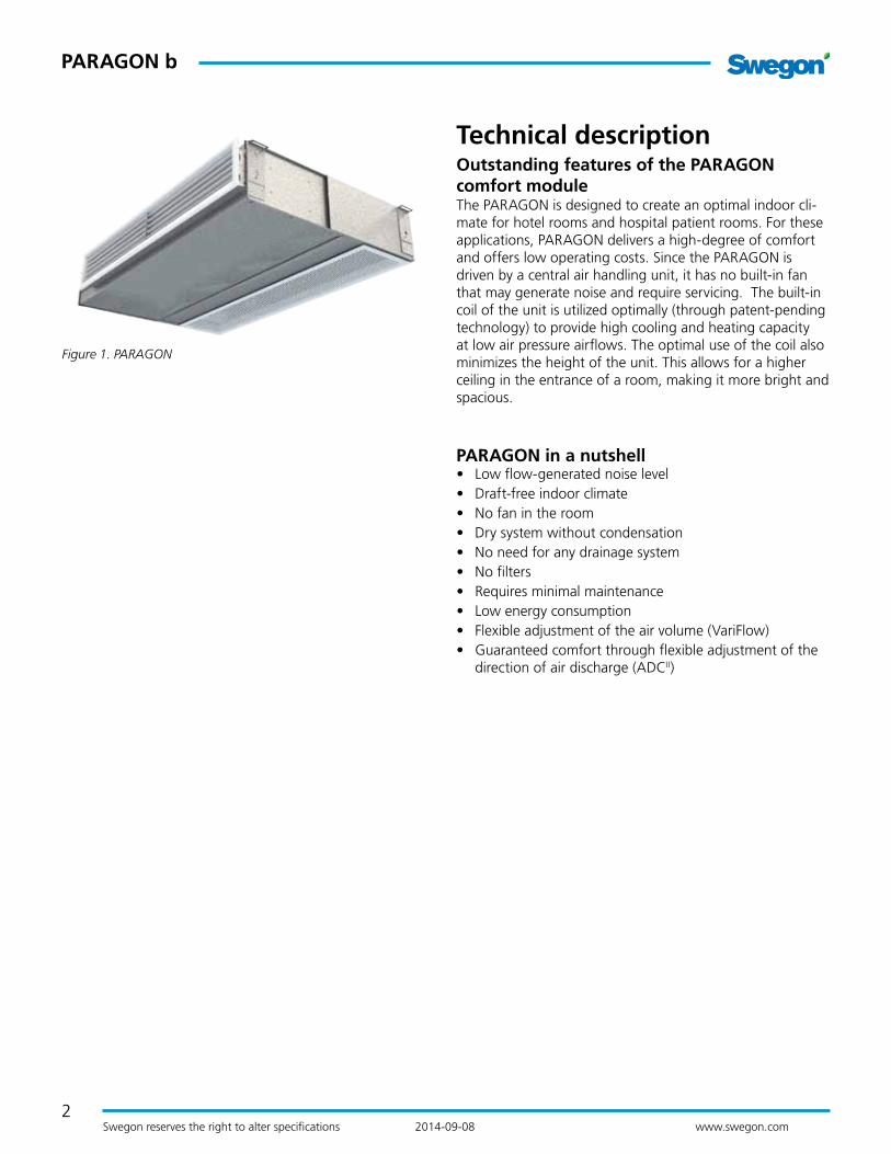
Figure 1. PARAGON
Technical descriptionOutstanding features of the PARAGON comfort moduleThe PARAGON is designed to create an optimal indoor cli-mate for hotel rooms and hospital patient rooms. For these applications, PARAGON delivers a high-degree of comfort and offers low operating costs. Since the PARAGON is driven by a central air handling unit, it has no built-in fan that may generate noise and require servicing. The built-in coil of the unit is utilized optimally (through patent-pending technology) to provide high cooling and heating capacity at low air pressure airflows. The optimal use of the coil also minimizes the height of the unit. This allows for a higher ceiling in the entrance of a room, making it more bright and spacious.
PARAGON in a nutshell• Low flow-generated noise level• Draft-free indoor climate• No fan in the room• Dry system without condensation• No need for any drainage system• No filters• Requires minimal maintenance• Low energy consumption• Flexible adjustment of the air volume (VariFlow)• Guaranteed comfort through flexible adjustment of the
direction of air discharge (ADCII)

3
PAR
AG
ON
b
PARAGON b
Swegon reserves the right to alter specifications 2014-09-08 www.swegon.com
How the Unit OperatesHotel & Hospital
The primary air is supplied through a duct connection in the rear edge of the unit and this builds up positive pressure inside the unit. The positive pressure distributes the primary air at relatively high velocity via two rows of nozzle holes, one row in the upper edge and one row in the lower edge of the outlet. The high velocity of the primary air creates negative pressure which generates induction of the room air. The recirculation air is drawn up through the recircula-tion grille of the unit and flows on through the coil where it is cooled, heated, if required, or just passes untreated, before it mixes with the primary air and is discharged into the room.
The supply air discharged into hotel rooms and hospital patient rooms is distributed as straight as possible by allow-ing it to follow the ceiling, i.e. utilize the Coanda effect. This enables the air to reach all the way to the perimeter wall. If Fan-shape air distribution is desirable, this is simply achieved by means of the ADCII (Anti Draft Control) feature, which is included as standard in all PARAGON comfort modules. If vertical air distribution is desirable, this is achieved by setting the louvers of the outlet grille to slant upward or downward. If you like, you can lock the angle setting of the outlet grille using an accessory that secures the louvers in fixed position.
Figure 2. PARAGON cooling function 1 = Primary air 2 = Induced room air 3 = Primary air mixed with chilled room air
Figure 3. PARAGON heating function 1 = Primary air 2 = Induced room air 3 = Primary air mixed with heated room air
Figure 4. Air distribution with the PARAGON in a hotel room
Figure 5. Air distribution with the PARAGON in a hospital patient room

4
PARAGON b
Swegon reserves the right to alter specifications 2014-09-08 www.swegon.com
Figure 6. Fan shape air distribution with ADCII
Figure 7. PARAGON ADCII
Figure 8. Vertical air distribution with adjustable louvers in the supply air grille.
5
PAR
AG
ON
b
PARAGON b
Swegon reserves the right to alter specifications 2014-09-08 www.swegon.com
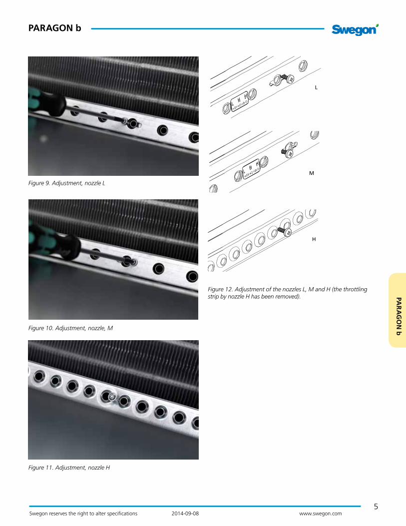
Figure 9. Adjustment, nozzle L
Figure 10. Adjustment, nozzle, M
Figure 11. Adjustment, nozzle H
H
L
M
Figure 12. Adjustment of the nozzles L, M and H (the throttling strip by nozzle H has been removed).

6
PARAGON b
Swegon reserves the right to alter specifications 2014-09-08 www.swegon.com
PlanningBoth planning and sizing are made easier by using Swegon’s ProSelect Project design computer program. ProSelect is available at Swegon’s home page: www.swegon.com.
SizingDesignations
P: Capacity (Btuh)
v: Velocity (fpm)
q: Airflow (cfm)
p: Air pressure, (inWG)
tr: Room temperature (°F)
tm: Mean water temperature (°F)
∆T: Temperature difference [tr–tm] (°F)
∆Tm: Temperature difference, between inlet and return (°F)
∆Tl: Temperature difference, between room and supply air (°F)
∆p: Water pressure drop (ftWG)
kp: Pressure drop constantSupplementary index: k = cooling, l = air, v = heating, i = commissioning
Recommended limit values, water
Max. recommended operating pressure (above coil only): 230 psi
Max. recommended test pressure (across coil only): 350 psi
Max. recommended pressure drop across standard valve: 6.7 ftWG
Min. permissible hot water flow: 0.2 gpm
Max. permissible inlet flow temperature: 140 °F
Min. permissible cooling water flow: 0.48 gpm
Lowest permissible inlet flow temperature: Should always be dimensioned so that the system works without condensation

7
PAR
AG
ON
b
PARAGON b
Swegon reserves the right to alter specifications 2014-09-08 www.swegon.com
Cooling Cooling capacityCooling capacities achieved from both the primary air and chilled water for various lengths of unit, damper settings and airflows are tabulated in Tables 3-10. The total cooling capacity for one unit is the sum of the cooling capacity of the primary air and the chilled water.
Below are some formula that enable the user to calculate which comfort module selection is applicable:
Cooling capacity of the air
Pl = 1.07384 · ql · ∆Tl
Pl Cooling capacity of the primary air (Btuh)
ql Flow of primary air (cfm)
∆Tl Temperature difference between primary air (tl) and room air (tr) (ºF)
Water's cooling capacity
Pk = 500 · qk · ∆Tk
Pk Cooling capacity of the water (Btuh)
qk Cooling water flow (gpm)
∆Tk Temperature difference of cooling water supply and return (ºF)
Pressure dropThe pressure drop on the water side can be calculated using the formula:
∆p = (q / kpk)2
∆p Pressure drop in the water circuit (ftWG)
q Water flow (gpm), see Diagram 1
kpk Pressure drop constant read from Table 1
Table 1. Pressure drop
Pressure drop, water
NC Length (in.) kpk Cooling
35 0.5947
43 0.5536
51 0.5207
59 0.4933
HC Length (in.) kpk Cooling
35 0.5097
43 0.4768
51 0.4494
59 0.4248
Table 2. Cooling Capacity for Natural Convection
Natural convection: The cooling capacity of water (Btuh) for ∆Tmk (°F )
Size 10 12 14 16 18 20
35 59 74 87 101 113 127
43 79 94 112 128 147 162
51 93 116 136 158 177 200
59 114 136 162 186 212 235
Capacity correctionDifferent water flows influence the available cooling effect to a certain degree. To calculate the actual cooling power based on a flow-dependant correction factor, use Swegon’s ProSelect computer program, available at www.swegon.com.
Diagram 1 – Cooling capacityThe function between cooling capacity Pk (Btuh), change in temperature ∆Tk (°F) and cooling water flow qk (gpm).
Diagram 2. Water flow – capacity correction
0.5 0.7 0.9 1.1 1.3 1.5
1.05
1.0
0.95
0.9
1.1
0.6 0.8 1.0 1.2 1.4 1.6
k
q (gpm)
Pk (Btuh)
6000
7000
8000
9000
5000
4000
3000
2000
1000
00.4 0.6 0.8 1.0 1.2 1.4 1.6 1.8
qk (gpm)
∆Tk(ºF)=
2ºF
4ºF
6ºF
8ºF
10ºF
.
.
.
.
. .
. .
.
.
. . .
. .
. .
(fpm)60 100 200 300 375
v

8
PARAGON b
Swegon reserves the right to alter specifications 2014-09-08 www.swegon.com
Table 3 – Cooling capacity, NC, 0.28 inWGLength of the unit
Nozzle settings
Air-flow
Noise level 1)
Nozzle pressure
pi
Cooling capacity, primary air (Btuh) ∆Tl (°F)
Cooling capacity of water (Btuh) for ∆Tmk 2)
(°F)Pressure
drop con-stant, air
in. cfm dB(A) inWG 10 14 18 22 10 12 14 16 18 20 kpl
35 L L 26 <20 0.28 285 398 512 626 766 917 1066 1217 1369 1520 50.20
35 M M 34 <20 0.28 360 504 648 791 837 1005 1172 1338 1502 1668 63.26
35 H H 58 <20 0.28 617 864 1111 1358 1012 1205 1395 1585 1778 1968 108.44
43 L L 34 <20 0.28 370 519 667 815 979 1176 1371 1565 1758 1951 64.93
43 M M 43 <20 0.28 462 646 831 1016 1080 1297 1511 1723 1939 2151 81.66
43 H H 74 <20 0.28 800 1120 1440 1760 1306 1556 1804 2050 2297 2543 140.24
51 L L 41 <20 0.28 440 616 792 969 1204 1443 1682 1921 2160 2396 77.65
51 M M 52 <20 0.28 553 774 995 1217 1328 1590 1852 2114 2375 2637 97.73
51 H H 89 <20 0.28 956 1338 1720 2103 1603 1906 2209 2513 2816 3115 167.34
59 L L 35 <20 0.28 376 526 677 827 1267 1529 1793 2062 2328 2597 65.93
59 M M 60 <20 0.28 639 895 1150 1406 1543 1858 2175 2491 2809 3128 112.12
59 H H 91 21 0.28 977 1368 1759 2150 1855 2210 2567 2923 3276 3629 171.36
Table 4 – Cooling capacity, NC, 0.40 inWGLength of the unit
Nozzle settings
Air-flow
Noise level 1)
Nozzle pressure
pi
Cooling capacity, primary air (Btuh) ∆Tl (°F)
Cooling capacity of water (Btuh) for ∆Tmk 2)
(°F)Pressure
drop con-stant, air
in. cfm dB(A) inWG 10 14 18 22 10 12 14 16 18 20 kpl
35 L L 32 <20 0.40 344 481 619 756 896 1071 1245 1420 1590 1764 50.20
35 M M 40 <20 0.40 430 601 773 945 985 1175 1365 1554 1744 1934 63.26
35 H H 68 20 0.40 736 1030 1324 1618 1167 1390 1614 1835 2055 2275 108.44
43 L L 41 <20 0.40 440 616 792 969 1159 1384 1607 1831 2055 2278 64.93
43 M M 52 20 0.40 553 774 995 1217 1271 1516 1763 2007 2249 2492 81.66
43 H H 89 22 0.40 956 1338 1720 2103 1505 1794 2082 2368 2655 2936 140.24
51 L L 49 <20 0.40 526 737 947 1158 1418 1695 1972 2246 2519 2792 77.65
51 M M 62 21 0.40 666 932 1198 1465 1558 1861 2162 2461 2761 3057 97.73
51 H H 106 23 0.40 1138 1594 2049 2504 1840 2197 2551 2900 3249 3598 167.34
59 L L 42 21 0.40 446 624 802 980 1500 1803 2109 2414 2720 3024 65.93
59 M M 71 22 0.40 762 1067 1372 1677 1808 2168 2531 2892 3256 3616 112.12
59 H H 108 26 0.40 1165 1631 2097 2563 2123 2532 2944 3352 3761 4167 171.36
1) The specified noise level is applicable to connection without damper or with fully open damper. In other cases where the airflow is demand-controlled with motor-driven dampers, the required data can be read from Swegon’s ProSelect sizing program. Room attenua-tion = 10 dB
2) The specified capacities are based on a complete unit including standard distribution and recirculation grille. Without grille the water capacity increases by approx. 5%. With ADCII adjusted to Fan shape you lose approx. 5% in water capacity. The primary air capacity is not affected.
NOTE! 1. The total cooling capacity is the sum of the air-based and water-based cooling capacities. 2. NC = Normal Capacity version

9
PAR
AG
ON
b
PARAGON b
Swegon reserves the right to alter specifications 2014-09-08 www.swegon.com
Table 5 – Cooling capacity, NC, 0.60 inWGLength of the unit
Nozzle settings
Air-flow
Noise level 1)
Nozzle pressure
pi
Cooling capacity, primary air (Btuh) ∆Tl (°F)
Cooling capacity of water (Btuh) for ∆Tmk 2)
(°F)Pressure
drop con-stant, air
in. cfm dB(A) inWG 10 14 18 22 10 12 14 16 18 20 kpl
35 L L 39 <20 0.60 419 586 754 921 1053 1254 1455 1652 1850 2051 50.20
35 M M 49 25 0.60 526 737 947 1158 1151 1371 1591 1807 2020 2236 63.26
35 H H 84 26 0.60 902 1263 1624 1984 1344 1602 1859 2117 2372 2626 108.44
43 L L 50 <20 0.60 542 759 976 1193 1357 1618 1876 2134 2389 2646 64.93
43 M M 64 26 0.60 682 955 1227 1500 1485 1766 2046 2327 2604 2880 81.66
43 H H 108 27 0.60 1165 1631 2097 2563 1734 2067 2398 2732 3061 3391 140.24
51 L L 60 20 0.60 644 902 1160 1417 1660 1979 2298 2614 2928 3239 77.65
51 M M 76 27 0.60 811 1135 1459 1784 1818 2163 2508 2850 3191 3529 97.73
51 M H 103 28 0.60 1106 1548 1991 2433 2009 2396 2780 3163 3546 3925 132.54
59 L L 51 25 0.60 548 767 986 1205 1768 2117 2466 2815 3164 3509 65.93
59 M M 87 28 0.60 934 1308 1682 2055 2113 2530 2944 3358 3771 4184 112.12
59 M H 110 29 0.60 1181 1654 2126 2599 2305 2756 3204 3655 4102 4547 141.91
Table 6 – Cooling capacity, NC, 0.80 inWGLength of the unit
Nozzle settings
Air-flow
Noise level 1)
Nozzle pressure
pi
Cooling capacity, primary air (Btuh) ∆Tl (°F)
Cooling capacity of water (Btuh) for ∆Tmk 2)
(°F)Pressure
drop con-stant, air
in. cfm dB(A) inWG 10 14 18 22 10 12 14 16 18 20 kpl
35 L L 45 23 0.80 483 677 870 1063 1158 1378 1598 1814 2031 2247 50.20
35 M M 56 29 0.80 607 849 1092 1335 1266 1505 1741 1976 2212 2443 63.26
43 L L 58 24 0.80 623 872 1121 1370 1495 1778 2062 2344 2621 2898 64.93
43 M M 73 30 0.80 784 1097 1411 1725 1635 1942 2249 2554 2853 3153 81.66
51 L L 70 25 0.80 746 1045 1343 1642 1838 2183 2531 2874 3218 3556 77.65
51 M M 88 31 0.80 940 1315 1691 2067 2007 2382 2758 3130 3502 3870 97.73
59 L L 59 29 0.80 634 887 1140 1394 1964 2343 2725 3105 3485 3864 65.93
59 M M 100 32 0.80 1079 1511 1943 2374 2327 2782 3234 3685 4133 4581 112.12
1) The specified noise level is applicable to connection without damper or with fully open damper. In other cases where the airflow is demand-controlled with motor-driven dampers, the required data can be read from Swegon’s ProSelect sizing program. Room attenua-tion = 10 dB
2) The specified capacities are based on a complete unit including standard distribution and recirculation grille. Without grille the water capacity increases by approx. 5%. With ADCII adjusted to Fan shape you lose approx. 5% in water capacity. The primary air capacity is not affected.
NOTE! 1. The total cooling capacity is the sum of the air-based and water-based cooling capacities. 2. NC = Normal Capacity version

10
PARAGON b
Swegon reserves the right to alter specifications 2014-09-08 www.swegon.com
Table 7 – Cooling capacity, HC, 0.28 inWGLength of the unit
Nozzle settings
Air-flow
Noise level 1)
Nozzle pressure
pi
Cooling capacity, primary air (Btuh) ∆Tl (°F)
Cooling capacity of water (Btuh) for ∆Tmk 2)
(°F)Pressure
drop con-stant, air
in. cfm dB(A) inWG 10 14 18 22 10 12 14 16 18 20 kpl
35 L L 26 <20 0.28 285 398 512 626 774 929 1083 1237 1389 1544 50.20
35 M M 34 <20 0.28 360 504 648 791 875 1050 1222 1396 1567 1741 63.26
35 H H 58 <20 0.28 617 864 1111 1358 1089 1294 1501 1707 1911 2112 108.44
43 L L 34 <20 0.28 370 519 667 815 1006 1204 1401 1601 1799 1996 64.93
43 M M 43 <20 0.28 462 646 831 1016 1128 1353 1576 1797 2020 2244 81.66
43 H H 74 <20 0.28 800 1120 1440 1760 1404 1673 1940 2205 2471 2733 140.24
51 L L 41 <20 0.28 440 616 792 969 1232 1479 1723 1968 2212 2454 77.65
51 M M 52 <20 0.28 553 774 995 1217 1384 1661 1935 2209 2481 2754 97.73
51 H H 88 <20 0.28 950 1330 1711 2091 1720 2045 2372 2697 3020 3343 167.34
59 L L 35 <20 0.28 376 526 677 827 1295 1564 1836 2110 2382 2659 65.93
59 M M 60 <20 0.28 639 895 1150 1406 1620 1912 2226 2551 2881 3207 112.12
59 H H 90 21 0.28 972 1361 1749 2138 1985 2372 2756 3136 3515 3895 171.36
Table 8 – Cooling capacity, HC, 0.40 inWGLength of the unit
Nozzle settings
Air-flow
Noise level 1)
Nozzle pressure
pi
Cooling capacity, primary air (Btuh) ∆Tl (°F)
Cooling capacity of water (Btuh) for ∆Tmk 2)
(°F)Pressure
drop con-stant, air
in. cfm dB(A) inWG 10 14 18 22 10 12 14 16 18 20 kpl
35 L L 32 <20 0.40 344 481 619 756 942 1123 1305 1487 1669 1851 50.20
35 M M 40 <20 0.40 430 601 773 945 1057 1257 1461 1663 1867 2068 63.26
35 H H 68 20 0.40 736 1030 1324 1618 1280 1527 1774 2017 2259 2502 108.44
43 L L 41 <20 0.40 440 616 792 969 1217 1452 1687 1925 2154 2388 64.93
43 M M 52 20 0.40 553 774 995 1217 1359 1621 1883 2145 2406 2664 81.66
43 H H 89 22 0.40 956 1338 1720 2103 1655 1973 2289 2604 2918 3229 140.24
51 L L 49 <20 0.40 526 737 947 1158 1493 1781 2068 2357 2645 2930 77.65
51 M M 62 21 0.40 666 932 1198 1465 1670 1992 2311 2634 2952 3271 97.73
51 H H 106 23 0.40 1138 1594 2049 2504 2025 2415 2803 3190 3573 3956 167.34
59 L L 42 21 0.40 446 624 802 980 1575 1894 2212 2531 2853 3172 65.93
59 M M 71 22 0.40 762 1067 1372 1677 1950 2288 2654 3037 3420 3799 112.12
59 H H 108 26 0.40 1165 1631 2097 2563 2330 2785 3238 3685 4137 4581 171.36
1) The specified noise level is applicable to connection without damper or with fully open damper. In other cases where the airflow is demand-controlled with motor-driven dampers, the required data can be read from Swegon’s ProSelect sizing program. Room attenua-tion = 10 dB
2) The specified capacities are based on a complete unit including standard distribution and recirculation grille. Without grille the water capacity increases by approx. 5%. With ADCII adjusted to Fan shape you lose approx. 5% in water capacity. The primary air capacity is not affected.
NOTE! 1. The total cooling capacity is the sum of the air-based and water-based cooling capacities. 2. HC = High Capacity version
11
PAR
AG
ON
b
PARAGON b
Swegon reserves the right to alter specifications 2014-09-08 www.swegon.com
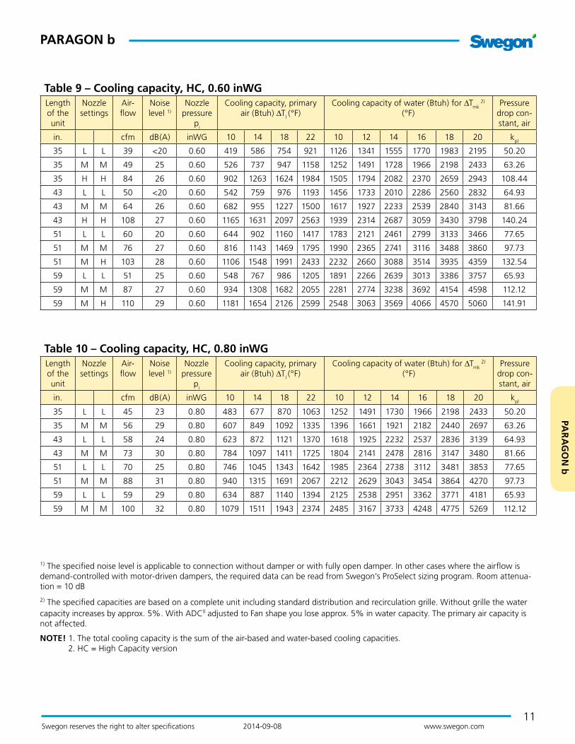
Table 9 – Cooling capacity, HC, 0.60 inWGLength of the unit
Nozzle settings
Air-flow
Noise level 1)
Nozzle pressure
pi
Cooling capacity, primary air (Btuh) ∆Tl (°F)
Cooling capacity of water (Btuh) for ∆Tmk 2)
(°F)Pressure
drop con-stant, air
in. cfm dB(A) inWG 10 14 18 22 10 12 14 16 18 20 kpl
35 L L 39 <20 0.60 419 586 754 921 1126 1341 1555 1770 1983 2195 50.20
35 M M 49 25 0.60 526 737 947 1158 1252 1491 1728 1966 2198 2433 63.26
35 H H 84 26 0.60 902 1263 1624 1984 1505 1794 2082 2370 2659 2943 108.44
43 L L 50 <20 0.60 542 759 976 1193 1456 1733 2010 2286 2560 2832 64.93
43 M M 64 26 0.60 682 955 1227 1500 1617 1927 2233 2539 2840 3143 81.66
43 H H 108 27 0.60 1165 1631 2097 2563 1939 2314 2687 3059 3430 3798 140.24
51 L L 60 20 0.60 644 902 1160 1417 1783 2121 2461 2799 3133 3466 77.65
51 M M 76 27 0.60 816 1143 1469 1795 1990 2365 2741 3116 3488 3860 97.73
51 M H 103 28 0.60 1106 1548 1991 2433 2232 2660 3088 3514 3935 4359 132.54
59 L L 51 25 0.60 548 767 986 1205 1891 2266 2639 3013 3386 3757 65.93
59 M M 87 27 0.60 934 1308 1682 2055 2281 2774 3238 3692 4154 4598 112.12
59 M H 110 29 0.60 1181 1654 2126 2599 2548 3063 3569 4066 4570 5060 141.91
Table 10 – Cooling capacity, HC, 0.80 inWGLength of the unit
Nozzle settings
Air-flow
Noise level 1)
Nozzle pressure
pi
Cooling capacity, primary air (Btuh) ∆Tl (°F)
Cooling capacity of water (Btuh) for ∆Tmk 2)
(°F)Pressure
drop con-stant, air
in. cfm dB(A) inWG 10 14 18 22 10 12 14 16 18 20 kpl
35 L L 45 23 0.80 483 677 870 1063 1252 1491 1730 1966 2198 2433 50.20
35 M M 56 29 0.80 607 849 1092 1335 1396 1661 1921 2182 2440 2697 63.26
43 L L 58 24 0.80 623 872 1121 1370 1618 1925 2232 2537 2836 3139 64.93
43 M M 73 30 0.80 784 1097 1411 1725 1804 2141 2478 2816 3147 3480 81.66
51 L L 70 25 0.80 746 1045 1343 1642 1985 2364 2738 3112 3481 3853 77.65
51 M M 88 31 0.80 940 1315 1691 2067 2212 2629 3043 3454 3864 4270 97.73
59 L L 59 29 0.80 634 887 1140 1394 2125 2538 2951 3362 3771 4181 65.93
59 M M 100 32 0.80 1079 1511 1943 2374 2485 3167 3733 4248 4775 5269 112.12
1) The specified noise level is applicable to connection without damper or with fully open damper. In other cases where the airflow is demand-controlled with motor-driven dampers, the required data can be read from Swegon’s ProSelect sizing program. Room attenua-tion = 10 dB
2) The specified capacities are based on a complete unit including standard distribution and recirculation grille. Without grille the water capacity increases by approx. 5%. With ADCII adjusted to Fan shape you lose approx. 5% in water capacity. The primary air capacity is not affected.
NOTE! 1. The total cooling capacity is the sum of the air-based and water-based cooling capacities. 2. HC = High Capacity version

12
PARAGON b
Swegon reserves the right to alter specifications 2014-09-08 www.swegon.com
HeatingHeating capacityHeating capacities are tabulated in Tables 13-16.
The heating capacity of the water can be calculated using the formula:
Water's heating capacityPv = 500 · qv · ∆Tv where
Pv Heating capacity of the water (Btuh)
qv Flow of heating water (gpm)
∆Tv Temperature difference between the heating water’s flow and return flow (°F)
Diagram 3 - Heating capacityThe function between heating capacity Pv (Btuh), change in temperature ∆Tv (°F) and heating water flow, qv (gpm).
Pv (Btuh)
12000
14000
16000
18000
10000
8000
6000
4000
2000
00.2 0.4 0.6 0.8 1.0 1.2 1.4 1.6
qv (gpm)
∆Tv(ºF)=
3ºF
6ºF
9ºF
12ºF
15ºF
18ºF
21ºF
24ºF27ºF30ºF
(fpm)40 60 80 100 120 140 160
v
Table 12 - Heating capacity for natural convection
Heat emission when ∆Tmv [°F] (Btuh)
Length (in.) 9 18 27 36 45 54 63
35 7 24 48 82 119 167 218
43 10 31 61 106 157 215 283
51 10 38 75 126 191 263 348
59 14 44 89 150 225 314 413
Pressure dropThe pressure drop on the water side can be calculated using the formula:
∆pv = (qv / kpv)2 where
∆pv Pressure drop in heating circuit (ftWG)
qv Flow of heating water (gpm), see Diagram 3
kpv Pressure drop constant for heating circuit, see Table 11
For a more detailed pressure drop calculation, use the Sw-egon ProSelect computer program available at www.swegon.com.
Table 11. Pressure dropPressure drop, water
NC Length (in.) kpv Heating
35 0.4878
43 0.4549
51 0.4275
59 0.4056
HC Length (in.) kpv Heating
35 0.4878
43 0.4549
51 0.4275
59 0.4056

13
PAR
AG
ON
b
PARAGON b
Swegon reserves the right to alter specifications 2014-09-08 www.swegon.com
Table 13 – Heating capacity, NC 2)/HC 3), 0.28 inWGLength of the unit
Nozzle settings
Airflow Noise level 1)
Nozzle pressure pi
Heating capacity, water (Btuh) for ∆Tmv (°F) Pressure drop
constant, air
in. cfm dB(A) inWG 10 20 30 40 50 60 kpl
35 L L 26 <20 0.28 436 873 1314 1759 2205 2651 50.20
35 M M 34 <20 0.28 558 1114 1668 2221 2775 3329 63.26
35 H H 58 <20 0.28 588 1182 1806 2434 3069 3711 108.44
43 L L 34 <20 0.28 562 1128 1701 2275 2851 3430 64.93
43 M M 43 <20 0.28 717 1436 2150 2865 3579 4291 81.66
43 H H 74 <20 0.28 759 1530 2333 3145 3968 4798 140.24
51 L L 41 <20 0.28 690 1386 2089 2794 3501 4213 77.65
51 M M 52 <20 0.28 880 1762 2638 3513 4387 5263 97.73
51 H H 88 <20 0.28 929 1869 2855 3846 4851 5865 167.34
59 L L 35 <20 0.28 819 1640 2471 3305 4143 4983 65.93
59 M M 60 <20 0.28 1043 2081 3116 4151 5187 6220 112.12
59 H H 90 21 0.28 1100 2213 3376 4551 5742 6942 171.36
Table 14 – Heating capacity, NC 2)/HC 3), 0.40 inWGLength of the unit
Nozzle settings
Airflow Noise level 1)
Nozzle pressure pi
Heating capacity, water (Btuh) for ∆Tmv (°F) Pressure drop
constant, air
in. cfm dB(A) inWG 10 20 30 40 50 60 kpl
35 L L 32 <20 0.40 512 1020 1532 2044 2556 3071 50.20
35 M M 40 <20 0.40 633 1264 1885 2503 3119 3734 63.26
35 H H 68 20 0.40 645 1298 1985 2681 3387 4099 108.44
43 L L 41 <20 0.40 659 1317 1980 2639 3301 3965 64.93
43 M M 52 20 0.40 816 1631 2431 3228 4023 4817 81.66
43 H H 89 22 0.40 830 1673 2563 3460 4370 5289 140.24
51 L L 49 14 0.40 808 1616 2427 3237 4051 4862 77.65
51 M M 62 21 0.40 1001 1999 2981 3960 4934 5909 97.73
51 H H 106 23 0.40 1017 2050 3138 4236 5353 6479 167.34
59 L L 42 21 0.40 955 1909 2867 3824 4784 5745 65.93
59 M M 71 22 0.40 1183 2362 3522 4680 5832 6983 112.12
59 H H 108 26 0.40 1206 2428 3713 5013 6334 7667 171.36
NOTES
1) The specified noise level is applicable to connection without damper or with fully open damper. In other cases where the airflow is demand-controlled with motor-driven dampers, the required data can be read from Swegon’s ProSelect sizing program. Room attenua-tion = 10 dB
2) NC = Normal Capacity version
3) HC = High Capacity version

14
PARAGON b
Swegon reserves the right to alter specifications 2014-09-08 www.swegon.com
Table 15 – Heating capacity, NC 2)/HC 3), 0.60 inWGLength of the unit
Nozzle settings
Airflow Noise level 1)
Nozzle pressure pi
Heating capacity, water (Btuh) for ∆Tmv (°F) Pressure drop constant, air
in. cfm dB(A) inWG 10 20 30 40 50 60 kpl
35 L L 39 <20 0.60 595 1186 1777 2365 2953 3541 50.20
35 M M 49 25 0.60 717 1433 2127 2821 3507 4191 63.26
35 H H 84 26 0.60 709 1425 2188 2959 3744 4538 108.44
43 L L 50 <20 0.60 766 1531 2294 3054 3812 4571 64.93
43 M M 64 26 0.60 929 1849 2748 3642 4529 5414 81.66
43 H H 108 27 0.60 914 1841 2824 3818 4831 5855 140.24
51 L L 60 20 0.60 940 1876 2809 3741 4669 5596 77.65
51 M M 76 27 0.60 1138 2269 3371 4466 5556 6642 97.73
51 M H 103 28 0.60 1127 2260 3425 4599 5783 6973 132.54
59 L L 51 25 0.60 1108 2217 3316 4416 5514 6610 65.93
59 M M 87 27 0.60 1343 2680 3980 5275 6561 7842 112.12
59 M H 110 29 0.60 1331 2674 4051 5435 6831 8236 141.91
Table 16 – Heating capacity, NC 2)/HC 3), 0.80 inWGLength of the unit
Nozzle settings
Airflow Noise level 1)
Nozzle pressure pi
Heating capacity, water (Btuh) for ∆Tmv (°F) Pressure drop constant, air
in. cfm dB(A) inWG 10 20 30 40 50 60 kpl
35 L L 45 23 0.80 652 1302 1944 2587 3229 3867 50.20
35 M M 56 29 0.80 781 1553 2303 3047 3786 4521 63.26
43 L L 58 24 0.80 842 1681 2511 2159 2986 4989 64.93
43 M M 73 30 0.80 1005 2006 2972 3932 4886 5833 81.66
51 L L 70 25 0.80 1031 2061 3080 4096 5110 6120 77.65
51 M M 88 31 0.80 1236 2459 3645 4822 5992 7155 97.73
59 L L 59 29 0.80 1221 2439 3644 4845 6043 7239 65.93
59 M M 100 32 0.80 1460 2908 4308 5702 7085 8459 112.12
NOTES
1) The specified noise level is applicable to connection without damper or with fully open damper. In other cases where the airflow is demand-controlled with motor-driven dampers, the required data can be read from Swegon’s ProSelect sizing program. Room attenua-tion = 10 dB
2) NC = Normal Capacity version
3) HC = High Capacity version

15
PAR
AG
ON
b
PARAGON b
Swegon reserves the right to alter specifications 2014-09-08 www.swegon.com
ExampleCoolingConditionsA hotel room having dimensions L × W × H = 12 × 10 × 9 ft is to be ventilated, cooled and heated by the PARAGON. The cooling demand is estimated to be 22 Btuh/sq.ft for an occupied room and normal load conditions.
In rare cases, the load conditions may be slightly higher and are then estimated to be 27 Btuh/sq.ft. The cooling demand is then a total of 22 x 12 x 10 = 2640 Btuh and 27 x 12 x 10 = 3240 Btuh respectively.
Under normal load conditions, the supply air flow should be 51 cfm and have a temperature of 59 °F. For higher load conditions, an increase in supply air flow up to a maximum of 63 cfm is permissible. The available duct pressure is kept constant at 0.65 inWG. The sound level must not exceed 25 dB(A) under normal circumstances and 30 dB(A) in the event of higher load conditions.
The design room temperature in the summer case is set to 75 °F. The inlet temperature of the cooling water is 57 °F and its outlet temperature on returning is 61 °F.
SolutionThe 59 °F supply air temperature and the 75 °F room tem-perature provide ∆Tl = 16 °F.
The temperature increase of the cooling water is 61 – 57 = 4 °F.
The mean temperature of the cooling water is: (57 + 61) / 2 = 59 °F. The 59 °F mean temperature of the cooling water and the 75 °F room temperature provide ∆Tmk = 16 °F.
Normal case
The cooling capacity of the supply air is calculated: Pl = 1.07384 x 51 x 16 = 876 Btuh. The residual cooling capacity demanded by the cooling water is: 2640 – 876 = 1764 Btuh.
In Table 4, we read that a PARAGON 43 with MM nozzle adjustment produces 2007 Btuh in cooling capacity for 51 cfm supply airflow, 0.40 inWG nozzle pressure and ∆Tmk = 16 °F. This is more than adequate to meet the cooling demand.
From Diagram 1 we read 1764 Btuh capacity and an increase in cooling water temperature of 4 °F as well as a water flow of approx. 0.88 gpm. Using the water flow and pressure drop constant kpk which is taken from Table 1. The pressure drop across the coil will then be: ∆Pk = (0.88 / 0.5536)2 = 2.5 ftWG.
Read from Table 4, the sound level is 20 dB(A), which meets the max. permissible level of 25 dB(A) required.
High loadUnder high load conditions, a motorized damper is opened to set boost level by the control equipment. A supply air-flow of 63 cfm is obtained, if the nozzle pressure is 0.60 inWG, which is in conformity with the demand on maximal 63 cfm.
Calculate the cooling capacity of the supply air: Pl = 1.07384 x 60 x 16 = 1031 Btuh. The residual cooling capacity demanded by the cooling water is: 2890 – 881 = 2009 Btuh.
In Table 5, we read that a PARAGON 43 with MM nozzle adjustment produces 2327 Btuh in cooling capacity for 63 cfm supply airflow, 0.60 inWG nozzle pressure and ∆Tmk = 16 °F. This is adequate to meet the higher cool-ing load.
From Diagram 1 we read 2209 Btuh capacity and an increase in cooling water temperature of 4 °F as well as a water flow of approx. 1.10 gpm. Using the water flow and pressure drop constant kpk which is taken from Table 1. The pressure drop across the coil will then be: ∆Pk = (1.10 / 0.5536)2 = 3.95 ftWG.
The sound level as specified in Table 5 and is 26 dB(A), which is clearly lower than the requirement of maximal permissible 30 dB(A) under max load conditions.
However note that the sound levels in the tables do not include the sound generated from the damper.

16
PARAGON b
Swegon reserves the right to alter specifications 2014-09-08 www.swegon.com
HeatingConditionsThe prerequisites are the same as in the example for cool-ing, with the exception that the design room temperature in the winter case is 72 °F and the supply air temperature is 64 °F.
The heating load is estimated to be 14.7 Btuh/sq.ft for an occupied room and normal load conditions. In rare cases, the load conditions may be slightly higher and are then esti-mated to be 19.8 Btuh/sq.ft. The heating demand is then a total of 14.7 x 11.3 × 10.7 = 1777 Btuh and 19.8 x 11.3 × 10.7 = 2394 Btuh respectively.
The inlet temperature of the heating water is 122 °F and the return temperature is 111 °F.
SolutionThe 64 °F supply air temperature is lower than the 72 °C design room temperature and then has a negative effect on the heating capacity: 1.07384 x 42 x (72 – 64) = 361 Btuh.
The heating demand for heating water then increases to 1777 + 363 = 2140 Btuh and 2394 + 363 = 2757 Btuh respectively.
The 117 °F mean temperature of the heating water and the 72 °F room temperature provide ∆Tmv = 117 – 72 = 45 °F.
In Table 13, we read that a PARAGON 43 with MM nozzle adjustment produces 3222 Btuh in heating capacity for 43.2 cfm supply airflow, 0.28 inWG nozzle pressure and ∆Tmv = 45 K.
This is enough to manage the heating demand when normal load (2096 Btuh). From Table 14, we read 48 Btuh for a supply airflow of 51.7 cfm, which meets the demand under high load conditions (2713 Btuh).
From Diagram 3 we read a capacity of 3222 Btuh and a 11 °F decrease in heating water temperature as well as a water flow of approx. 0.602 gpm.
By means of the water flow and the pressure drop constant kpv which is taken from Table 11. The pressure drop can be calculated across the coil: ∆pv = (0.602 / 0.4549)2 = 1.75 ftWG.
The same calculation for the heating capacity during high load provides the pressure drop ∆pv = (0.666 / 0.4549)2 = 2.14 ftWG.
ProSelectPlanning and sizing based on given design considerations can also be carried out in Swegon’s ProSelect project design program.
ProSelect is available at Swegon’s home page: www.swegon.com.
AcousticsNatural attenuationNatural attenuation is the total reduction in sound power from duct to room including the end reflection of the unit.
Table 17. Natural attenuation with lining
Natural attenuation (dB) for mid frequency f (Hz) ∆Lw [dB]
63 125 250 500 1k 2k 4k 8k
24 14 9 6 9 14 14 18

17
PAR
AG
ON
b
PARAGON b
Swegon reserves the right to alter specifications 2014-09-08 www.swegon.com
AccessoriesSupply air kit – PARAGON T-SAK-VAVA motor-driven damper is needed in applications where the user wants to apply demand control to the supply air by means of CONDUCTOR control equipment The damper causes a certain amount of flow-generated sound. There-fore a sound attenuator is also needed to guarantee a low sound level in the room.
As standard the connecion has an OD of 5 in.. There is also a connection with an OD of 4 in. available, which is suitable when the space is limited.
The following components are included in PARAGON T-SAK-VAV:
Motor-driven damper CRTc including Belimo CM24
Sound attenuator CLA rectangular sound atte-nuator with circular connection spigots
Sound attenuator
Motor-driven damper
Figure 13. PARAGON T-SAK-VAV
Supply air kit – PARAGON T-SAK-CAVA commissioning damper is needed to ensure the correct airflow if a simpler regulation system with constant airflow has been selected. Commissioning dampers also generate a certain amount of sound. We therefore recommend the use of a sound attenuator for keeping the sound level at a minimum.
As standard the connecion has an OD of 5 in.. There is also a connection with an OD of 4 in. available, which is suitable when the space is limited.
The following components are included in PARAGON T-SAK-CAV:
Commissioning damper CRPc-9 commissioning damper with perforated damper blade and manually adjustable blade.
Sound attenuator CLA rectangular sound atte-nuator with circular connec-tion spigots
Sound attenuator
Commissioning damper
Figure 14. PARAGON T-SAK-CAV

18
PARAGON b
Swegon reserves the right to alter specifications 2014-09-08 www.swegon.com
Extract air kit – PARAGON T-EAK-VAVIf the supply air is demand-controlled, the extract air also needs to be feed-back controlled. An extract air kit is needed for balancing the supply air and the extract air. Precisely like the supply air kit, this kit consists of a motor-driven damper and a sound attenuator. In addition an extract air register and two alternative mounting frames are included: one with a nipple and one with a joint.
Motor-driven damper CRTc including Belimo CM24
Sound attenuator CLA rectangular sound atte-nuator with circular connection spigots
Extract air register EXCa and accompanying moun-ting frames: one with circular connection spigot and one with circular connection sleeve.
Motor-driven damperSound attenuator
Extract air register
Figure 15. Extract air kit, PARAGON T-EAK-VAV
Extract air kit – PARAGON T-EAK-CAVA commissioning damper is needed in systems with con-stant airflows in order to balance the extract airflow with the supply airflow.
Therefore a kit designed for constant airflows is available for simpler systems. This kit contains commissioning damper, sound attenuator, extract air register and mounting frames.
Commissioning damper CRPc-9 commissioning damper with perforated damper blade and manually adjustable blade.
Sound attenuator CLA rectangular sound atte-nuator with circular connec-tion spigots
Extract air register EXCa and accompanying mounting frames: one with a nipple and one with a joint.
Figure 16. Extract air kit - PARAGON T-EAK-CAV
Commissioning damperSound attenuator
Extract air register

19
PAR
AG
ON
b
PARAGON b
Swegon reserves the right to alter specifications 2014-09-08 www.swegon.com
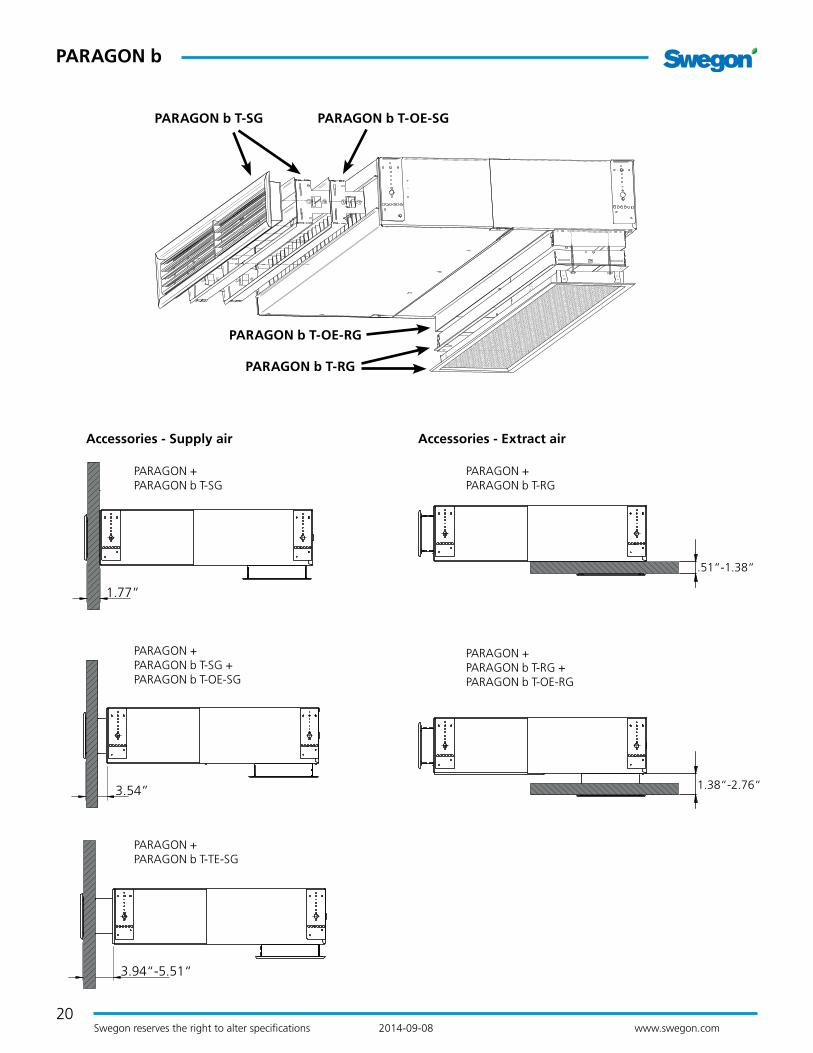
Accessories – Supply airThe supply air grille is supplied with a 1.77" spigot / frame as standard however it can be combined with an extra spigot for use as an extension in increments of 1.77" mm.
A grille with a telescopic spigot that covers an interval of 3.94" - 5.51" between the module and wall is available as an optional extra. Cannot be combined with the standard frame stated above.
PARAGON b T-SG Supply air grille incl. 1.77" spigot
PARAGON b T-OE-SG Extra 1.77" spigot for the supply air grille
PARAGON b T-TE-SG Telescopic spigot for the supply air grille, 3.94"-5.51"
Accessories - Return airThe return air grille is supplied with a 1.38" spigot/frame which can be inserted into the module and which then covers the .51"-1.38" interval between the module and the ceiling.
An extra spigot for the return air grille can be ordered as an accessory and then covers the 1.38"-2.76" interval installed together with the standard spigot.
PARAGON b T-RG Return air grille incl. .51"-1.38" spigot
PARAGON b T-OE-RG Extra 1.38"-2.76" spigot for the return air grille
20
PARAGON b
Swegon reserves the right to alter specifications 2014-09-08 www.swegon.com
Accessories - Supply air
PARAGON + PARAGON b T-SG
PARAGON + PARAGON b T-SG + PARAGON b T-OE-SG
PARAGON + PARAGON b T-TE-SG
Accessories - Extract air
PARAGON + PARAGON b T-RG
.51“-1.38“
PARAGON + PARAGON b T-RG + PARAGON b T-OE-RG
1.38“-2.76“
1.77”
3.54”
3.94“-5.51“
PARAGON b T-SG PARAGON b T-OE-SG
PARAGON b T-RG
PARAGON b T-OE-RG

21
PAR
AG
ON
b
PARAGON b
Swegon reserves the right to alter specifications 2014-09-08 www.swegon.com
SYST MS M8 suspension kitIn the applications in which the PARAGON is not mounted in direct contact with the ceiling, there is a suspension kit available in order to simplify hanging it at the level desired.
Figure 17. Suspension kit, SYST MS M8 (L = according to ordering key)
InstallationAssemblyThe PARAGON is delivered with four mounting brackets designed for installation directly against the ceiling or instal-lation suspended from the ceiling. The mounting brackets allow a certain amount of further adjustment after the comfort module/ceiling mounting brackets has/ have been mounted as accurately as possible. This enables you to posi-tion the supply spigot correctly in relation to the wall and the grille. The next step is to connect the air duct, cooling pipes and heating pipes.
The SYST MS M8 suspension kit (must be ordered separa-tely) can be used to advantage in applications in which the PARAGON should not be mounted tight against the ceiling. For detailed mounting instructions, see separate document available for downloading at www.swegon.com.
Water connectionsAll water pipes (supply/return – cooling/heating) are delive-red as stub copper pipes with OD 0.5 in. x length 0.04 in..
NOTE! Support sleeves must be used if compression ring couplings are fitted. It is important use a pipe wrench to adequately restrain the pipe connections when tightening external connections to prevent damage to the connection pipes.
Air connectionA 5 in. air duct including gasket is connected directly to a circular connection spigot.
If the supply air kit is included in the installation, connect the parts in the following order, viewed from the PARA-GON:
1. Comfort module PARAGON
2. Air duct
3. Sound attenuator CLA
4. Air duct
5. CRT damper
Note that the supply and extract air kit is also available with an OD of 4 in.. This kit is suitable for use if the space is lim-ited and low airflows are discharged into the room.
FinishingThe work of building the soffit around the terminal can begin when the PARAGON has been completely installed. PARAGON is adapted so that load-bearing T-bar systems in combination with mineral wool slabs or the like could be used to build the soffit. Plasterboard also works well. To make your work simpler, detailed dimensions for cutting the opening are specified below the “Dimensions” section on page 22 in this brochure. More detailed information is also available in separate installation instructions at www.swegon.com.
MaintenanceSince the PARAGON operates without any built-in fan, without filter and without a drainage system, very little maintenance is required. In a hotel room or a hospital room, it is normally sufficient to vacuum clean the back side of the coil every six months to remove loose dust. A simple visual inspection of connections and wiping the supply air grille and return air grille with a damp cloth is also recom-mended. Avoid aggressive cleaning agents which may harm painted surfaces. Normally a mild soap or alcohol solution is fully adequate for cleaning. Note that the dry operation without condensation minimises the risk of bacteria growth that otherwise is occurs in wet systems.
The requirement for maintenance is yet lower in an office room, since this type of environment is normally much more dust-free, and this allows longer intervals between schedu-led maintenance. It is normally enough to clean the coil in an office room once every second year.
22
PARAGON b
Swegon reserves the right to alter specifications 2014-09-08 www.swegon.com
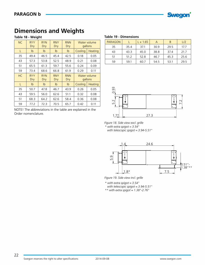
Dimensions and WeightsTable 18 - Weight
NC RYY Dry
RYN Dry
RNY Dry
RNN Dry
Water volume gallons
L lb lb lb lb Cooling Heating
35 49.4 46.5 45.4 42.5 0.18 0.05
43 57.3 53.8 52.5 48.9 0.21 0.08
51 65.5 61.3 59.7 55.6 0.24 0.09
59 73.4 68.6 66.8 61.9 0.29 0.11
HC RYY Dry
RYN Dry
RNY Dry
RNN Dry
Water volume gallons
L lb lb lb lb Cooling Heating
35 50.7 47.8 46.7 43.9 0.26 0.05
43 59.5 56.0 62.6 51.1 0.32 0.08
51 68.3 64.2 62.6 58.4 0.36 0.08
59 77.2 72.3 70.5 65.7 0.42 0.11
NOTE! The abbreviations in the table are explained in the Order nomenclature.
Figure 18. Side view excl. grille
Figure 19. Side view incl. grille
PARAGON L L + 1.65 A B L/2
35 35.4 37.1 30.9 29.5 17.7
43 43.3 45.0 38.8 37.4 21.7
51 51.2 52.8 46.7 45.3 25.6
59 59.1 60.7 54.5 53.1 29.5
Table 19 - Dimensions
1.8*
0.51“-1.38“**
1.4 24.6
7.5
5.9
5.2
7.2
0.93
1.7* 27.3
* with extra spigot = 3.54" with telescopic spigot = 3.94-5.51"
* with extra spigot = 3.54" with telescopic spigot = 3.94-5.51" ** with extra spigot = 1.38"-2.76"

23
PAR
AG
ON
b
PARAGON b
Swegon reserves the right to alter specifications 2014-09-08 www.swegon.com
0
2
02.99.9
7.2
L
8.3
3.5
5.1
4.9
A1B 2
B1A2
ø
L/2
C
Figure 20. View of the back side with connection on the right-hand side - R.
A1 = Chilled water supply A2 = Chilled water return C = Supply air B1 = Hot water supply B2 = Hot water return D = Cable grommets
Connection on the right hand side – R
L
A4.5B5.3
0.5 0.5
c -
c 24
.6
Figure 21a. Bottom view
L
AB 5.3
4.5
L + 1.65
Figure 22. Top view
0.5”
c-c 1.57”
Figure 21b. Mounting bracket
24
PARAGON b
Swegon reserves the right to alter specifications 2014-09-08 www.swegon.com
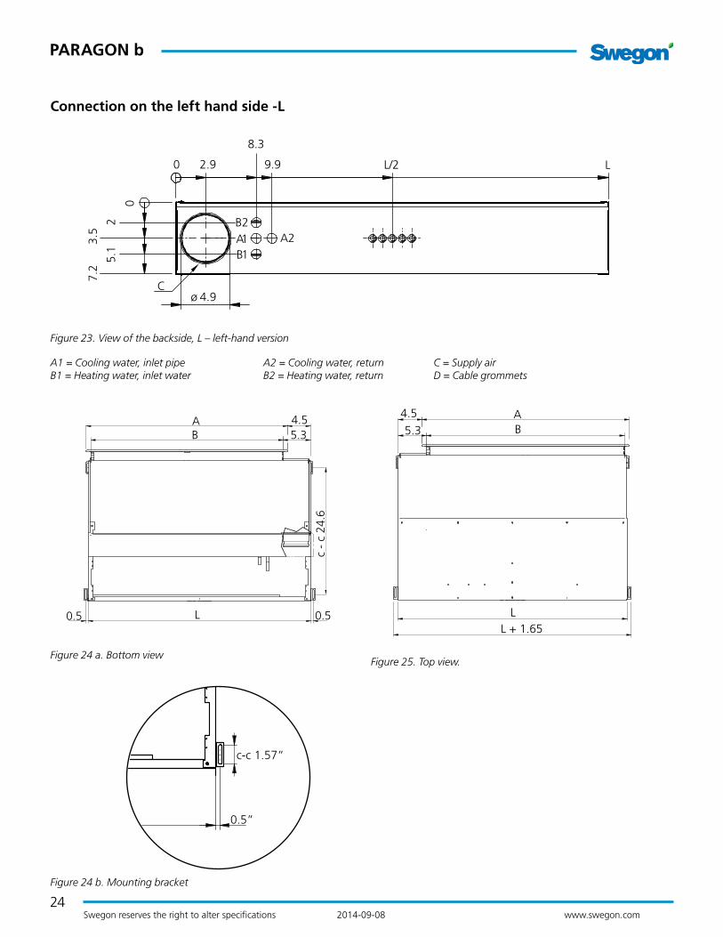
Connection on the left hand side -L
L
A 4.5B 5.3
0.5 0.5
c -
c 24
.6
Figure 24 a. Bottom view
0
2
0 2.9 9.9
7.2
L
8.3
3.5
5.1
4.9
A1B 2
B1A2
ø
L/2
C
Figure 23. View of the backside, L – left-hand version
A1 = Cooling water, inlet pipe A2 = Cooling water, return C = Supply air B1 = Heating water, inlet water B2 = Heating water, return D = Cable grommets
L
AB5.3
4.5
L + 1.65
Figure 25. Top view.
0.5”
c-c 1.57”
Figure 24 b. Mounting bracket

25
PAR
AG
ON
b
PARAGON b
Swegon reserves the right to alter specifications 2014-09-08 www.swegon.com
Dimensions, accessories
Figure 26. Supply air kit, PARAGON T-SAK-VAV
A
B
Figure 27. Supply air kit, PARAGON T-SAK-VAV-5
Spiral ducts are not included. Spiral duct A: Min. length: 13.0 in. Spiral duct B: Min. length: 2.8 in.
Figure 28. Supply air kit, PARAGON T-SAK-VAV-4
Size 4 spiral ducts and sleeve are not included. Spiral duct A: Min. length: 13.0 in. Spiral duct B: Min. length: 2.8 in.
A
B
Figure 29. Supply air kit, PARAGON T-SAK-CAV-5
Spiral ducts are not included. Spiral duct A: Min. length: 13.0 in. Spiral duct B: Min. length: 2.8 in.
A
B
Figure 30. Supply air kit, PARAGON T-SAK-CAV-4
Size 4 spiral ducts and sleeve are not included. Spiral duct A: Min. length: 13.0 in. Spiral duct B: Min. length: 2.8 in.

26
PARAGON b
Swegon reserves the right to alter specifications 2014-09-08 www.swegon.com
Figure 31. Extract air kit, PARAGON T-EAK
A
B
Figure 32. Extract air kit, PARAGON T-EAK-VAV
Available for connection sizes 5 in. and 4 in. Spiral ducts and jointing sleeve are not included A: Min. length: 30.3 in. B: Min. length: 14.2 in.
AB
Figure 33. Extract air kit, PARAGON T-EAK-CAV
Available for connection sizes 5 in. and 4 in. Spiral ducts and jointing sleeve are not included A: Min. length: 30.3 in. B: Min. length: 14.2 in.

27
PAR
AG
ON
b
PARAGON b
Swegon reserves the right to alter specifications 2014-09-08 www.swegon.com
Figure 34. Dimensions CLA sound attenuator. Included in PARA-GON T-SAK and PARAGON T-EAK.
Figure 35. Dimensions CRT motor-driven damper. Included in PARAGON T-SAK-VAV and PARAGON T-EAK-VAV.
Figure 36. Dimensions CRP commissioning damper. Included in PARAGON T-SAK-CAV and PARAGON T-EAK-CAV.
22.4 +0.2/-0
19.7 +0.2/-01.8
8.2 / 9.3
6 / 7
3.9
/ 4
.9
3.9
/ 4
.9
8.3
5.7
/ 6.7
5.1
2.2
3.9
/ 4
.9
8.3
4.1
6 / 7
.5
3.3

28
PARAGON b
Swegon reserves the right to alter specifications 2014-09-08 www.swegon.com
Ordering keySpecificationType PARAGON comfort module for cooling, heating and ventilation.
Delivery demarcationSwegon’s limits of supply are at the connection points for water and air.
At these connection points, the plumbing contractor con-nects to plain pipe end and/or suitable connectors, fills the system, bleeds it and tests the pressure in the circuits.
The ventilation contractor connects to the duct connections with dimensions as specified on the basic size drawing in the section "Dimensions".
The building contractor cuts the openings in the corridor wall for the supply air duct, in the interior wall and suspen-ded ceiling for the supply air and extract air grilles and in the bathroom ceiling for the extract air duct.
The PARAGON ordering key
PARAGON b aaaa- b- cc- d- ef
Version:
Length (in.) 35, 43, 51 and 59
Function:A = CoolingB = Cooling and heating
Capacity variant NC – Normal version HC – High capacity version
Connection side R - Right L - Left
Flow variant Upper nozzle row: L, M, H Lower nozzle row: L, M, H
Example:
PARAGON b-43-B-NC-R-LM
29
PAR
AG
ON
b
PARAGON b
Swegon reserves the right to alter specifications 2014-09-08 www.swegon.com
Ordering Key, Accessories
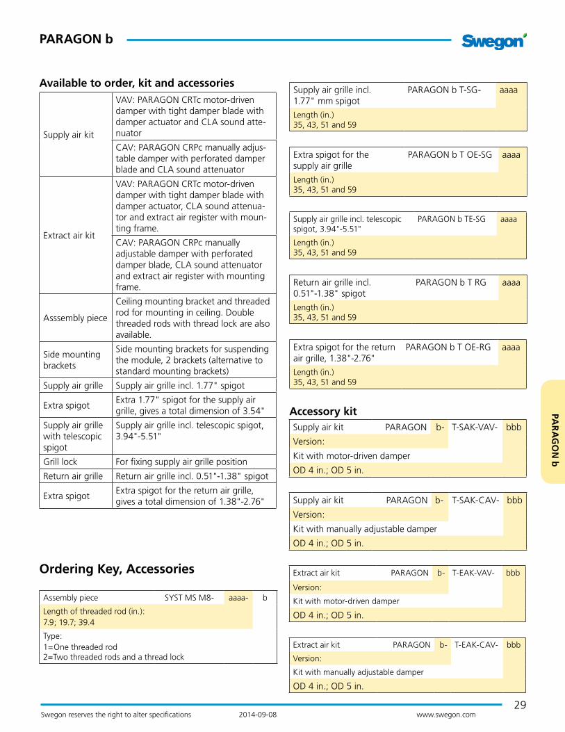
Assembly piece SYST MS M8- aaaa- b
Length of threaded rod (in.):7.9; 19.7; 39.4
Type:1=One threaded rod 2=Two threaded rods and a thread lock
Supply air kit PARAGON b- T-SAK-VAV- bbb
Version:
Kit with motor-driven damper
OD 4 in.; OD 5 in.
Supply air kit PARAGON b- T-SAK-CAV- bbb
Version:
Kit with manually adjustable damper
OD 4 in.; OD 5 in.
Extract air kit PARAGON b- T-EAK-VAV- bbb
Version:
Kit with motor-driven damper
OD 4 in.; OD 5 in.
Extract air kit PARAGON b- T-EAK-CAV- bbb
Version:
Kit with manually adjustable damper
OD 4 in.; OD 5 in.
Available to order, kit and accessories
Supply air kit
VAV: PARAGON CRTc motor-driven damper with tight damper blade with damper actuator and CLA sound atte-nuator
CAV: PARAGON CRPc manually adjus-table damper with perforated damper blade and CLA sound attenuator
Extract air kit
VAV: PARAGON CRTc motor-driven damper with tight damper blade with damper actuator, CLA sound attenua-tor and extract air register with moun-ting frame.
CAV: PARAGON CRPc manually adjustable damper with perforated damper blade, CLA sound attenuator and extract air register with mounting frame.
Asssembly piece
Ceiling mounting bracket and threaded rod for mounting in ceiling. Double threaded rods with thread lock are also available.
Side mounting brackets
Side mounting brackets for suspending the module, 2 brackets (alternative to standard mounting brackets)
Supply air grille Supply air grille incl. 1.77" spigot
Extra spigotExtra 1.77" spigot for the supply air grille, gives a total dimension of 3.54"
Supply air grille with telescopic spigot
Supply air grille incl. telescopic spigot, 3.94"-5.51"
Grill lock For fixing supply air grille position
Return air grille Return air grille incl. 0.51"-1.38" spigot
Extra spigotExtra spigot for the return air grille, gives a total dimension of 1.38"-2.76"
Supply air grille incl. 1.77" mm spigot
PARAGON b T-SG- aaaa
Length (in.) 35, 43, 51 and 59
Extra spigot for the supply air grille
PARAGON b T OE-SG aaaa
Length (in.) 35, 43, 51 and 59
Supply air grille incl. telescopic spigot, 3.94"-5.51"
PARAGON b TE-SG aaaa
Length (in.) 35, 43, 51 and 59
Return air grille incl. 0.51"-1.38" spigot
PARAGON b T RG aaaa
Length (in.) 35, 43, 51 and 59
Extra spigot for the return air grille, 1.38"-2.76"
PARAGON b T OE-RG aaaa
Length (in.) 35, 43, 51 and 59
Accessory kit