paper number - x2y · paper presented at 2005 sae world congress in detroit, mi, april 11 – 14...
TRANSCRIPT

Paper presented at 2005 SAE World Congress in Detroit, MI, April 11 – 14 2005 1
05AE-218
Electromagnetic Compatibility of Direct Current Motors in an Automobile Environment
Terry North DaimlerChrysler
Keith Frazier Ford Motor Company
Dale L. Sanders, James P. Muccioli X2Y Attenuators, LLC.
Copyright © 2004 SAE International
ABSTRACT
As the volume and complexity of electronics increases in automobiles, so does the complexity of the electromagnetic relationship between systems. The reliability and functionality of electronic systems in automobiles can be affected by noise sources such as direct current (DC) motors. A typical automobile has 25 to 100+ DC motors performing different tasks. This paper investigates the noise environment due to DC motors found in automobiles and the requirements that automobile manufacturers impose to suppress RF electromagnetic noise and conducted transients.
INTRODUCTION
Direct current (DC) motors in the automotive industry are generally divided into two different types. Brush commutated motors (BC) and electronically commutated motors (EC). BC motors use physical contact between the brushes and commutator to pass direct current to the wire coil around the armature stack. As the commutator rotates physical contact is momentarily broken and reestablished, creating small sparks which is the main source of unwanted RF (radio frequency) noise. EC motors use pulse-width modulated (PWM) signals (electronic switching) to control field effect transistors (FET) that supplies direct current to the wire coil around the armature stack. PWM signals typically contain RF harmonic content (rise/fall transition times) which in combination with radiated fields from FETs is the main source of unwanted RF noise.
Unwanted RF noise can take two forms, radiated and/or conducted. Radiated emission (RE) noise is electromagnetic noise that is emitted from a motor out into free space. Conducted emission (CE) noise is noise transmitted through leads from the motor. Radiated
noise can cause conducted noise or vise versa. Typically, applying electromagnetic compatibility (EMC) suppression will suppress both radiated and conducted noise, however the motor design itself may dictate the type of noise and effectiveness of EMC suppression components.
RF noise is typically defined in terms of the frequency range in which it occurs. If noise occurs in relative limited frequency range it is called narrowband (NB) noise and if noise occurs across a considerable frequency range it is called broadband (BB) noise. For typical unsuppressed DC motors, it is common to have noise from a few hertz to a gigahertz and beyond. However, in that frequency spectrum (hertz – gigahertz) automotive manufacturers generally single out particular frequency bands of interest for suppression.
EMC compliance also includes conducted transient suppression on leads (i.e. power leads, sensor/control leads/buses). The wire coil around the armature stack can be viewed as a lumped inductive element or load. A DC motor in a stall condition (worst-case scenario) that has current applied for a turn-on or turn-off condition results in the creation or collapse of a magnetic field in the coil generating a conducted positive and/or negative transient voltage in excess of several hundred volts. Conducted transients can cause problems with other electronics connected to the leads or with the motor itself. Transients are also a major factor in component specifications (i.e. voltage rating, reliability, stress etc.) used for EMC suppression. (An overview of components and their specifications is discussed later in this paper.)
Before investigating the EMC requirements that DC motors are subject to in the automotive industry, a brief discussion of EMC facilities, set-up, and test methodology should be briefly addressed. Most EMC
Paper presented at 2005 SAE World Congress in Detroit, MI, April 11 – 14 2005
testing in the automotive industry is based on CISPR 25. However, each manufacturer has their own adaptation with their own emphasis.
Within the automotive industry the main type of test chamber used is an absorber lined shielded enclosure also known as an anechoic chamber. The anechoic chamber is lined with an electromagnetic absorbing material that reduces wave reflections and moding. Most automotive manufacturers do not require absorbing material on the floor of the chamber, thus the chamber is semi-anechoic. The dimensions (size) and absorbing materials used typically have minimal effect on test measurements which allows for good correlation between chambers.
The test set-up within the chamber, connection, and layout of the device under test (DUT) and equipment can have a substantial effect on the test outcome. It is important to note that test set-ups vary among individual manufacturers.
The type of noise detection also varies among individual automobile manufacturers for conducted and radiated testing. If a motor is close to the accepted limits, the type of detection can mean the difference between passing and failing. The three types of detection used are peak, quasi-peak, and averaging. Peak records the maximum emission value for any set frequency, quasi-peak is weighted for specific charge and discharge time constants of the detector circuit (which is based upon the noise repetition rate) and average detection averages the peak values of a frequency. (The procedure for averaging can vary between manufacturers causing different results.) Peak, quasi-peak, and averaging will result in the same levels for narrowband, but yield different results for broadband measurements.
2
AUTOMOBILE MANUFACTURERS REQUIREMENTS AND STANDARDS
This section discusses the individual EMC requirements of DC motors for DaimlerChrysler, Ford Motor Company, and General Motors. The information within this section has been condensed for each of the respective manufacturers to highlight differences among each manufacturer and present information pertaining only to DC motor requirements. Information provided herein is believed to be accurate as of December 2004.
It should be noted that for the purposes of this paper an effort was made to define common terminology for consistency in the discussion of the individual automobile manufacturer’s requirements/specifications. For exact terminology and definitions used in each manufacturer’s requirements/specifications refer to original noted requirements/specifications. Additionally, specific information pertaining to exact test set-up or test equipment settings should also refer to the original noted requirements/specifications.
As previously discussed, DC motors are classified as either EC motors or BC motors. Automobile manufacturers require different EMC specifications for each classification of motor. Allowable emission levels are typically defined as either global limit levels or regional (North America, Europe, Japan) requirement limit levels.
DAIMLERCHRYSLER (DCX)
This section discusses the EMC requirements of EC motors and BC motors for DaimlerChrysler (DCX). DCX’s requirements for each type of motor can be found in: • DC-10614 “EMC Performance Requirements ---
Components” • DS-100 “Vehicle Design Requirements for EMC
Compliance” • DC-10615 “Electrical System Performance
Requirements for Electrical and Electronic Components”
Appendix A, B, and C in this paper gives an overview of the frequency spectrum and limit values.
DCX – EC Motors Radiated and Conducted RF Requirements
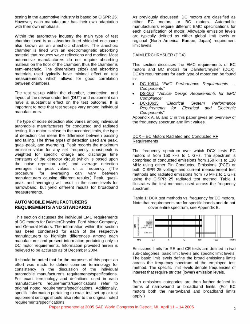
The frequency spectrum over which DCX tests EC motors is from 150 kHz to 1 GHz. The spectrum is comprised of conducted emissions from 150 kHz to 110 MHz using either Pin Conducted Emissions (PCE) or both CISPR 25 voltage and current measurement test methods and radiated emissions from 76 MHz to 1 GHz using the CISPR 25 radiated test method. Table 1 illustrates the test methods used across the frequency spectrum.
Table 1: DCX test methods vs. frequency for EC motors. Note that requirements are for specific bands and do not
cover entire spectrum, see Appendix B.
Emissions limits for RE and CE tests are defined in two sub-categories, basic limit levels and specific limit levels. The basic limit levels define the broad emissions limits across the frequency spectrum of the employed test method. The specific limit levels denote frequencies of interest that require stricter (lower) emission levels.
Both emissions categories are then further defined in terms of narrowband or broadband limits. (For EC motors both the narrowband and broadband limits apply.)

Paper presented at 2005 SAE World Congress in Detroit, MI, April 11 – 14 2005
The type of noise detection allowed for narrowband CE and RE is Peak or Average. For broadband, peak or quasi-peak detection is allowed to 200MHz; beyond 200MHz only peak detection is allowed.
3
A quick reference of the limit levels can be found in Appendix B of this paper. For exact specifications see below:
• PCE is described in detail in DC-10614 section 6.2. • CISPR 25 (voltage) is described in detail in DC-
10614 section 6.3. • CISPR 25 (current) is described in detail in DC-
10614 section 6.4. • CISPR 25 (radiated) is described in detail in DC-
10614 section 6.5.
DCX – BC Motors Radiated and Conducted RF Requirements
The frequency spectrum over which DCX tests BC motors is from 150 kHz to 200 MHz. The spectrum is comprised of conducted emissions from 150 kHz to 200 MHz using either Pin Conducted Emissions (PCE) or CISPR 25 voltage measurement test method. (Note that radiated emissions are NOT required for BC motors.) Table 2 illustrates the test methods used across the frequency spectrum.
Table 2: DCX test methods vs. frequency for BC motors. Note that requirements are for specific bands and do not
cover entire spectrum, see Appendix B.
Conducted emissions limits for both test methods are defined in two categories, basic limit levels and specific limit levels. The basic limit levels define the broad emissions limits across the frequency spectrum of the employed test method. The specific limit levels denote frequencies of interest that require stricter (lower) emission levels.
Both emissions categories are then defined in terms of narrowband or broadband limits. (For BC motors only the broadband limits apply.)
The type of noise detection allowed for the broadband CE is peak or quasi-peak detection.
A quick reference of the limit levels can be found in Appendix B of this paper. For exact specifications see below:
• PCE is described in detail in DC-10614 section 6.2.
• CISPR 25 (voltage) is described in detail in DC-10614 section 6.3.
DCX – EC and BC Motors Conducted Transient Requirements
EC and BC motors are tested with the fast transient setup from ISO 7637-2. Transient levels are categorized by the system voltage and are required not to exceed limits in Appendix C (DC-10614 section 6.7) regardless of wave shape.
GENERAL MOTORS (GM)
This section discusses the EMC requirements of EC motors, BC motors, and short duration (SD) motors for General Motors (GM). The requirements for GM can be found in: • GMW3103 “General Specification for
Electrical/Electronic Components and Subsystems; Electromagnetic Compatibility; Global EMC Component/Subsystem Validation Acceptance Process”
• GMW3097 “General Specification for Electrical/Electronic Components and Subsystems, Electromagnetic Compatibility (EMC)”
Appendix A, F, and G in this paper gives an overview of the frequency spectrum and limit values.
GM – EC Motors Radiated and Conducted RF Requirements
The frequency spectrum over which GM tests EC motors is from 150 kHz to 1.583 GHz in 11 specific bands of interest. The requirements include conducted emissions from 150kHz to 1.71MHz using CISPR 25 voltage (via artificial network) test method and radiated emissions in the 150 kHz to 1.583 GHz bands using the CISPR 25 Absorber-Lined Shielded Enclosure (ALSE) method. (GMW 3097 section 3.3.2 and GMW 3097 section 3.3.1 respectively).Table 3 illustrates the test methods used across the frequency spectrum. (Note that GM also allows the use of a reverberation chamber for radiated testing. However, this method of testing will become obsolete as of 01 July 2005 and thus is not covered in this paper.)
Table 3: GM test methods vs. frequency for EC motors. Note that requirements are for specific bands and do not
cover entire spectrum, see Appendix F.
Emissions limit levels for each test method are defined based on the type of motor, BC or EC. (GM categorizes BC motors as spark generated noise and EC motors as non-spark generated noise, thus limit levels are defined on that basis.) EC motors are required to meet both
Paper presented at 2005 SAE World Congress in Detroit, MI, April 11 – 14 2005
spark and non-spark generated noise levels for both radiated and conducted emissions.
EC motors are required to be tested as a system with its electronic control modules whether they are internal or external.
The type of noise detection for non-spark radiated and conducted emissions is peak. However if the non-spark emissions limit is exceeded using the peak detector, average detection may be used with a 6 dB more-restrictive non-spark limit (e.g. Peak limit level – 6dB = Average limit level). This is based on the inability to detect the module noise over the arcing noise of a motor when using the PK detector.
For the spark-generated portion of the requirements for EC motors, a quasi-peak (QP) detector is used for both radiated and conducted emissions measurement. (Note that, until July 1, 2005, GM permits conducted emissions to be measured with a peak detector, accompanied by a 13 dB higher allowance for the resultant emissions)
4
GM – EC Motor Transient Requirements
Test equipment used to test conducted transients shall comply with ISO 7637-1 and ISO 7637-2.3. The test plan is described in GMW3103 and requirements are noted in GMW3097 section 3.5.1.
Motors that may have stall conditions in an automobile are required to be tested in a “stall” condition. EC motors are required to be tested as a system with its electronic control modules whether they are internal or external. Transients are measured directly at the EC motor terminals. If control circuits are inside the EC motor assembly test probes must be place inside the assembly.
The voltage levels of conducted transients are not allowed to exceed +100v or -150v. Requirements are shown in Appendix G of this paper. If should be noted that EC motors may also require conducted transient immunity testing which is outside the scope of this paper.
GM – BC Motors Radiated and Conducted RF Requirements
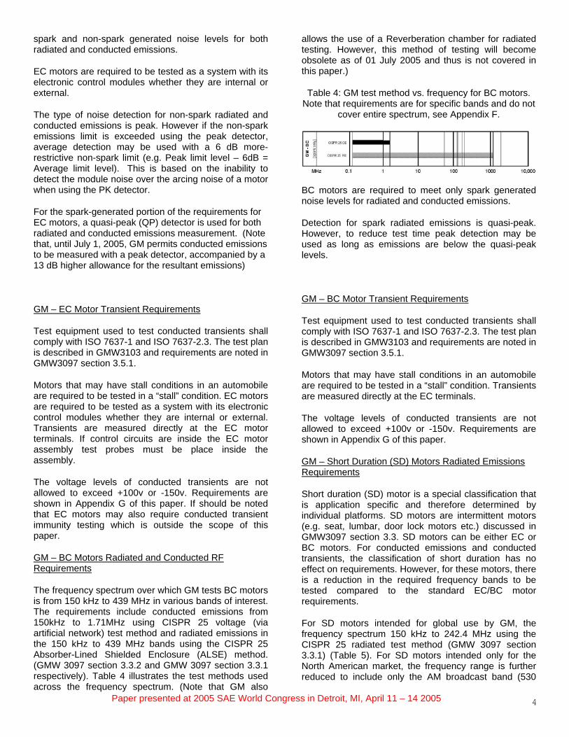
The frequency spectrum over which GM tests BC motors is from 150 kHz to 439 MHz in various bands of interest. The requirements include conducted emissions from 150kHz to 1.71MHz using CISPR 25 voltage (via artificial network) test method and radiated emissions in the 150 kHz to 439 MHz bands using the CISPR 25 Absorber-Lined Shielded Enclosure (ALSE) method. (GMW 3097 section 3.3.2 and GMW 3097 section 3.3.1 respectively). Table 4 illustrates the test methods used across the frequency spectrum. (Note that GM also
allows the use of a Reverberation chamber for radiated testing. However, this method of testing will become obsolete as of 01 July 2005 and thus is not covered in this paper.)
Table 4: GM test method vs. frequency for BC motors. Note that requirements are for specific bands and do not
cover entire spectrum, see Appendix F.
BC motors are required to meet only spark generated noise levels for radiated and conducted emissions.
Detection for spark radiated emissions is quasi-peak. However, to reduce test time peak detection may be used as long as emissions are below the quasi-peak levels.
GM – BC Motor Transient Requirements
Test equipment used to test conducted transients shall comply with ISO 7637-1 and ISO 7637-2.3. The test plan is described in GMW3103 and requirements are noted in GMW3097 section 3.5.1.
Motors that may have stall conditions in an automobile are required to be tested in a “stall” condition. Transients are measured directly at the EC terminals.
The voltage levels of conducted transients are not allowed to exceed +100v or -150v. Requirements are shown in Appendix G of this paper.
GM – Short Duration (SD) Motors Radiated Emissions Requirements
Short duration (SD) motor is a special classification that is application specific and therefore determined by individual platforms. SD motors are intermittent motors (e.g. seat, lumbar, door lock motors etc.) discussed in GMW3097 section 3.3. SD motors can be either EC or BC motors. For conducted emissions and conducted transients, the classification of short duration has no effect on requirements. However, for these motors, there is a reduction in the required frequency bands to be tested compared to the standard EC/BC motor requirements.
For SD motors intended for global use by GM, the frequency spectrum 150 kHz to 242.4 MHz using the CISPR 25 radiated test method (GMW 3097 section 3.3.1) (Table 5). For SD motors intended only for the North American market, the frequency range is further reduced to include only the AM broadcast band (530
Paper presented at 2005 SAE World Congress in Detroit, MI, April 11 – 14 2005
kHz to 1.71 MHz). The limits in these bands remain the same as for the general BC/EC motors.
(Note that GM also allows the use of a Reverberation chamber for radiated testing. However, this method of testing will become obsolete as of 01 July 2005 and thus is not covered in this paper.)
Table 5: GM test method vs. frequency for SD motors. Note that requirements are for specific bands and do not
cover entire spectrum, see Appendix F.
EC or BCCISPR 25 CE
CISPR 25 RE(voltage & current)
Note: conducted emissions and conducted transients spectrum/requirements depend on whether the motor is EC or BC and are not affected by the classification of "Short Duration". The classification of "Short Duration" is platform specific. Only radiated emission's
spectrum/requirements are affected by the classification of "Short Duration" and requirements are dependant on market.
GM
- SD
MHz 0.1 1 10 100 1000 10,000
Radiated emissions limit levels for SD motors are shown in Appendix F of this paper or in GMW 3097 section 3.3.1.
The type of noise detection for spark radiated emissions is quasi-peak. However, to reduce test time peak detection may be used as long as emissions are below the quasi-peak levels.
Limit levels for conducted emissions and conducted transients can also be found in this paper in Appendix F and G or in GMW 3097 sections 3.3.2 and 3.5 respectively.
FORD MOTOR COMPANY (FMC)
This section discusses the EMC requirements of EC motors, BC motors, and SD (short duration) motors for Ford Motor Company (FMC). The requirements for FMC can be found in: • ES-XW7T-1A278-AC “Component and Subsystem
Electromagnetic Compatibility Worldwide Requirements and Test Procedures” 10 October 2003.
5
Appendix A, D, and E in this paper gives an overview of the frequency spectrum and limit values.
FMC – EC Motor Radiated and Conducted RF Requirements
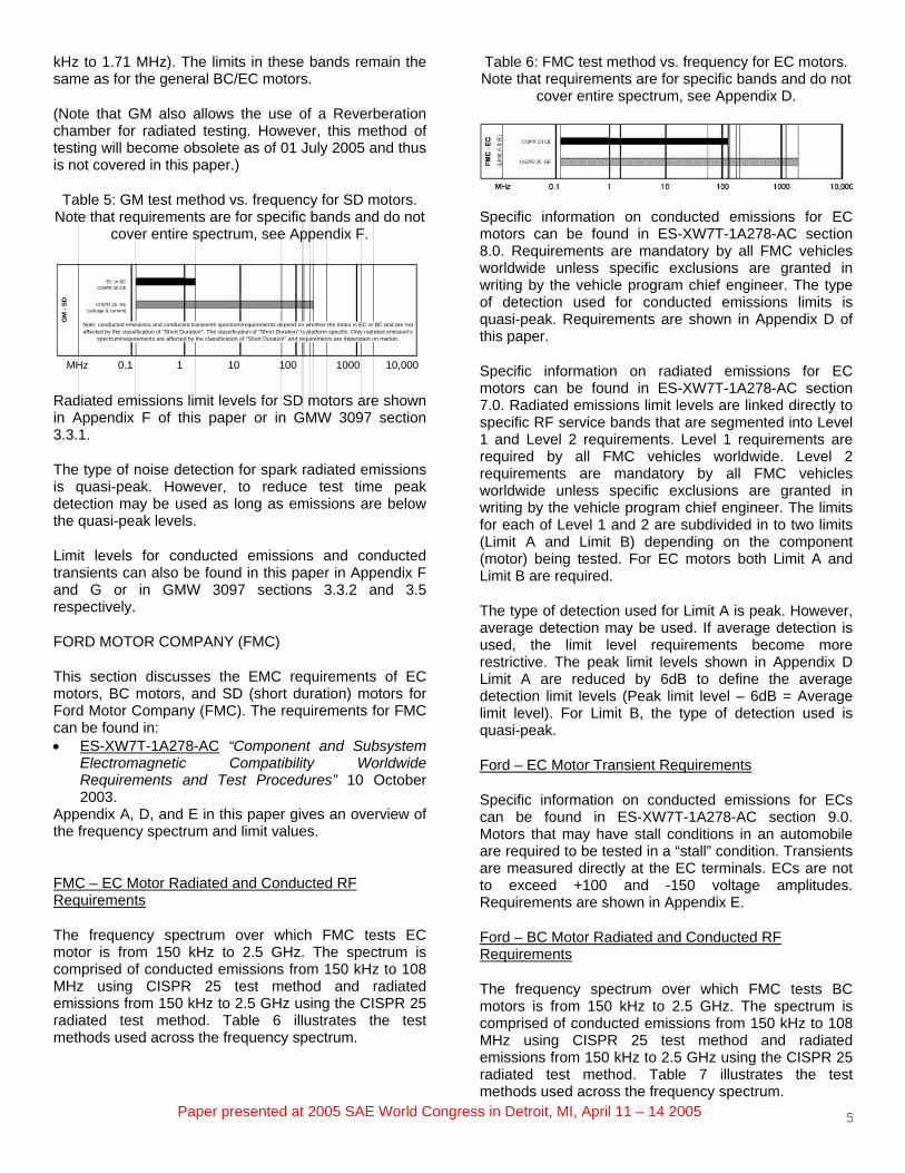
The frequency spectrum over which FMC tests EC motor is from 150 kHz to 2.5 GHz. The spectrum is comprised of conducted emissions from 150 kHz to 108 MHz using CISPR 25 test method and radiated emissions from 150 kHz to 2.5 GHz using the CISPR 25 radiated test method. Table 6 illustrates the test methods used across the frequency spectrum.
Table 6: FMC test method vs. frequency for EC motors. Note that requirements are for specific bands and do not
cover entire spectrum, see Appendix D.
Specific information on conducted emissions for EC motors can be found in ES-XW7T-1A278-AC section 8.0. Requirements are mandatory by all FMC vehicles worldwide unless specific exclusions are granted in writing by the vehicle program chief engineer. The type of detection used for conducted emissions limits is quasi-peak. Requirements are shown in Appendix D of this paper.
Specific information on radiated emissions for EC motors can be found in ES-XW7T-1A278-AC section 7.0. Radiated emissions limit levels are linked directly to specific RF service bands that are segmented into Level 1 and Level 2 requirements. Level 1 requirements are required by all FMC vehicles worldwide. Level 2 requirements are mandatory by all FMC vehicles worldwide unless specific exclusions are granted in writing by the vehicle program chief engineer. The limits for each of Level 1 and 2 are subdivided in to two limits (Limit A and Limit B) depending on the component (motor) being tested. For EC motors both Limit A and Limit B are required.
The type of detection used for Limit A is peak. However, average detection may be used. If average detection is used, the limit level requirements become more restrictive. The peak limit levels shown in Appendix D Limit A are reduced by 6dB to define the average detection limit levels (Peak limit level – 6dB = Average limit level). For Limit B, the type of detection used is quasi-peak.
Ford – EC Motor Transient Requirements
Specific information on conducted emissions for ECs can be found in ES-XW7T-1A278-AC section 9.0. Motors that may have stall conditions in an automobile are required to be tested in a “stall” condition. Transients are measured directly at the EC terminals. ECs are not to exceed +100 and -150 voltage amplitudes. Requirements are shown in Appendix E.
Ford – BC Motor Radiated and Conducted RF Requirements
The frequency spectrum over which FMC tests BC motors is from 150 kHz to 2.5 GHz. The spectrum is comprised of conducted emissions from 150 kHz to 108 MHz using CISPR 25 test method and radiated emissions from 150 kHz to 2.5 GHz using the CISPR 25 radiated test method. Table 7 illustrates the test methods used across the frequency spectrum.

Paper presented at 2005 SAE World Congress in Detroit, MI, April 11 – 14 2005
Table 7: FMC test method vs. frequency for BC motors. Note that requirements are for specific bands and do not
cover entire spectrum, see Appendix D.
Specific information on conducted emissions for BC motors can be found in ES-XW7T-1A278-AC section 8.0. Requirements are mandatory by all FMC vehicles worldwide unless specific exclusions are granted in writing by the vehicle program chief engineer. The type of detection used for conducted emissions limits is quasi-peak. Requirements are shown in Appendix D.
Specific information on radiated emissions for BC motors can be found in ES-XW7T-1A278-AC section 7.0. Radiated emissions limit levels are linked directly to specific RF service bands that are segmented into Level 1 and Level 2 requirements. Level 1 requirements are required by all FMC vehicles worldwide. Level 2 requirements are mandatory by all FMC vehicles worldwide unless specific exclusions are granted in writing by the vehicle program chief engineer. The limits for each of Level 1 and 2 are subdivided in to two limits (Limit A and Limit B) depending on the component being tested. For ECs only Limit B levels are required. The type of detection used for Limit B is quasi-peak. Requirements are shown in Appendix D.
Ford – BC Motor Transient Requirements
6
Specific information on conducted emissions for BC motors can be found in ES-XW7T-1A278-AC section 9.0. Motors that may have stall conditions in an automobile are required to be tested in a “stall” condition. Transients are measured directly at the BC terminals. BCs are not to exceed +100 and -150 voltage amplitudes. Requirements are shown in Appendix E.
EMC SUPPRESSION COMPONENTS
Components used for EMC suppression are either surface mounted components (SMC) or leaded components. Both have advantages and disadvantages that should be considered.
Leaded components are easier to place during manufacturing and can be soldered almost anywhere. However, parasitic impedance from the leads can severely limit the effective frequencies of operation along with the way the leads are bent and placed.
SMC do not have leads, thus they typically have higher and broader effective operating frequencies. The trade off of SMC is that they require a printed circuit board
(PCB) to be mounted to. With EC motors this is not a concern since EC motors already have circuitry on PCBs; but implementation of SMC in BC motors that do not have a brush card design may require more design thought. (If BC motors use a brush card instead of cantilevered brush springs or have other circuitry on a PCB, this may be a moot point.)
Most types of EMC suppression components come in both leaded and surface mount configurations. When possible, SMC should generally be used in order to meet current and future automotive requirements.
Other considerations for selecting an EMC suppression component that should be specified in the design are:
• Frequency range of operation • Voltage rating (DC voltage breakdown) • Failure mode (open or short) • Temperature operating range • Reliability • Stress test results • ESD rating • Impulse/surge test results • Component balance
Discussed in Table 8 are the general advantages and disadvantages of components typically used for EMC suppression in the automotive industry.
Table 8: Comparison of typical EMC suppression components.
Capacitor Advantages Disadvantages
• Leaded or surface mount
• Low cost
• Availability
• Can provide some transient suppression
• Failure mode “open”
• Narrow filtering band (requires multiple components for broadband filter)
• Requires multiple components for both common mode and differential mode noise filtering Low cost
Feed Thru Chip Capacitor Advantages Disadvantages
• Broad filtering band • Surface mount only
• Cost
• Failure mode is “short”
• Adds DC resistance

Paper presented at 2005 SAE World Congress in Detroit, MI, April 11 – 14 2005 7
Ferrite Beads Advantages Disadvantages
• Easy implementation
• Broad filtering band (effective below 300-500MHz)
• Filter both common mode and differential mode noise
• High temperatures cause saturation
• Size is determined by Amperes – prevent low frequency magnetic saturation
• Moderate filtering attenuation
• Cost
Inductor (Wound Iron Core) Advantages Disadvantages
• Broad filtering band (effective below 300-500MHz)
• Cost
• High temperatures cause saturation
• Size is determined by Amperes – prevent low frequency magnetic saturation
• Quality materials and tolerance add cost
Common Mode Choke (Iron Core) Advantages Disadvantages
• Broad filtering band (effective below 300-500MHz)
• High temperatures cause saturation
• Quality materials and tolerance add cost
Metal Oxide Varistor (MOV) Advantages Disadvantages
• Transient clamping • Cost
• No broadband filtering
• Internal energy dissipation can reduce transient clamping performance
Zener Diode Advantages Disadvantages
• Low cost transient clamping • Less robust over repeated transient strikes
• No broadband filtering
• Failure mode unpredictable
X2Y® Component Advantages Disadvantages
• Broad filtering band (DC – 6GHz)
• Low cost
• Single component filters 2 power leads
• Filters both common mode and differential mode noise
• Component tolerances inherent
• Some transient suppression
• Surface mount only
• Attachment location is critical
Figures 1 – 4 show some common production EMC suppression filters comprised of different components. Figure 5 shows the radiated emission suppression performance of each filter component combination.
Figure 1: Four component filter comprised of (2) capacitors and (2) inductors. (see Reference 1)
Figure 2: Five component filter comprised of (2) capacitors, (1) varistor, and (2) ferrites. (see Reference 1)
Figure 3: Seven component filter comprised of (2) capacitors, (2) inductors, (2) ferrites, and (1) varistor. (see Reference 1)
Figure 4: One component filter comprised of (1) X2Y. (see Reference 1)

Paper presented at 2005 SAE World Congress in Detroit, MI, April 11 – 14 2005
Figure 5: Radiated emission performance of filters in Figures 1 – 4. (see Reference 1)
DC MOTOR DESIGN FOR ELECTROMAGNETIC COMPATIBILITY (EMC)
With every design decision, trade offs are made. This section tries to highlight key discussions made during the design phase that knowingly or unknowingly affect EMC suppression.
Addressing EMC early in the design process gives motor designers more options for suppression techniques. This allows cost to be the driving consideration. When EMC problems develop at the end of the design process, meeting requirements becomes the driving consideration where production retooling, engineering resources and available fixes affect profitability.
In order for cost to drive EMC suppression techniques, it is important for automotive manufacturers to insure that all tier suppliers are aware of the requirements and a common strategy and responsibility is developed. Typically only first tier suppliers get mandates for EMC requirements; however DC motors are usually designed, built, and supplied by second and third tier suppliers. If EMC requirements only become known to second and third tier suppliers when production problems develop, cost for EMC suppression grows exponentially.
DESIGNING THE HOUSING
The most important decision is the motor housing. The housing should be metal or metalized and encompass both the magnets and brushes. Thickness of the metal or metalized material should be considered not just for mechanical and magnetic performance purposes but should also include shielding properties. Slots or holes in the housing should be eliminated or minimized near the brushes to keep from making them a “slot antenna” (Figure 5). Figure 6 shows the radiated emission performance between two motors, one with a slot near the brushes and the other without the slot. Both have an X2Y component inside for filtering.
Figure 6: The motor housing should be metal or metalized with no holes especially near brushes. (see Reference 2)
Figure 7: Radiated emission results of a motor with a hole near the brushes and one without a hole. Both motors have an X2Y filter component inside. (see Reference 3)
DESIGNING END CAPS
The end cap should also be metal or metalized to contain electromagnetic fields. Also, note that the design of the crimping tabs used to attach the end cap may couple noise if contact is made from inside and outside the housing, low electrical impedance is critical in this mechanical interface (Figure 8).
Figure 8: End caps should also be metal or metalized. The critical parameter is the location of the brushes with respect to the end cap. (see Reference 2)
8

Paper presented at 2005 SAE World Congress in Detroit, MI, April 11 – 14 2005
LEAD LOCATION
Leads or connector pins that exit the housing should be close together to reduce the current loop. This also allows easier implementation of filter components (Figure 9). Figure 10 shows the radiated emission results of leads apart versus together.
Figure 9: Diagram of preferred lead placement. (see Reference 2)
Figure 10: Radiated emission results of leads close together and far apart. Both tests use an X2Y filter component. (see Reference 4)
ELECTRICAL JOINTS
Joints are typically only designed with mechanical strength in mind. Electrical conductivity and shielding should also be considered. Joints should overlap and be interlocking. Oxidization and galvanic action should be prevented at the joints. Paint, powder coating, and oils should also be removed to promote conductivity over the frequency spectrum needed to be filtered (Figure 11).
Figure 11: Joints on motors should be designed not only for mechanical strength but to also have a low-impedance electrical path. (see Reference 2)
Filter components should be located just inside or outside the motor housing where leads exit. This keeps noise from coupling around the filter. Traces or leads that come to the filer should be minimized in length to reduce impedance and ensure noise gets to the filter. Depending on the application, filter components may need a non-conductive coating to protect from brush dust or a conductive carbon path (salt path) that may form over time.
CONCLUSION
Future trends in EMC DC motor suppression will require lower emission levels, have more frequencies of interest, and a broader frequency spectrum. In addition, as automobile manufacturers become more globalized they are moving toward universal modules across platforms. For motors, this means regional requirements will become global requirements.
Planning early in the motor design and having all tier suppliers aware of requirements is the key for cost effective EMC suppression.
Finally, over the past few years FMC, DCX, and GM have worked toward common requirements in many areas. Should this trend continue, a common EMC requirement for DC motors could benefit both the automobile manufacturers and suppliers. Having common requirements would streamline the design efforts of suppliers and provide for larger potential markets (multiple platforms and manufacturers). For automobile manufacturers it would promote competition and cost savings while ensuring specifications are meet.
ACKNOWLEDGMENTS
The authors of this paper would like to thank Mark Steffka and Don Seyerle from General Motors for their contributions, support, and time reviewing this paper. In addition, we would also like to thank Doug Walz at Johnson Electric for his support and time in reviewing this paper.
9
Paper presented at 2005 SAE World Congress in Detroit, MI, April 11 – 14 2005 10
REFERENCES
1. J.P. Muccioli, A.A. Anthony, W.M. Anthony, D. S. Walz, “Broadband Testing of Low Cost Filter Solutions for DC Motors,” Electrical Manufacturing & Coil Winding Association Expo 2000, Cincinnati, OH. November 01, 2000.
2. “X2Y® Technology in DC Motors,” Technical Presentation. www.x2y.com.
3. “DC Motor Design with X2Y® Example B,” Application Note # 4003. www.x2y.com.
4. “DC Motor Design with X2Y® Example C,” Application Note # 4004. www.x2y.com.
ADDITIONAL SOURCES
DC-10614 “EMC Performance Requirements --- Components,” Draft 7-29-2004, revision B.
DC-10615 “Electrical System Performance Requirements for Electrical and Electronic Components,” Date Published: 2003-05.
DS-100 “Vehicle Design Requirements for EMC Compliance,” Draft 27 Feb 2004.
GMW3103 “General Specification for Electrical/Electronic Components and Subsystems, Electromagnetic Compatibility, Global EMC Component/Subsystem Validation Acceptance Process,” August 2001.
GMW3097 “General Specification for Electrical/Electronic Components and Subsystems Electromagnetic Compatibility (EMC),” February 2004.
ES-XW7T-1A278-AC “Component and Subsystem Electromagnetic Compatibility Worldwide Requirements and Test Procedures,” Date Issued: October 10, 2003.
D.L. Sanders, J.P. Muccioli, A.A. Anthony, D.S. Walz, and D. Montone, “Using Image Planes on DC Motors to Filter High Frequency Noise,” International IEEE EMC Symposium 2004, Santa Clara, CA. August 09 – 13, 2004.
J.P. Muccioli, A.A. Anthony, W.M. Anthony, D.S. Walz, “Broadband KuTEM Omni-Cell Testing of Small DC Motors for a Low Cost Filter Solution,” International IEEE EMC Symposium, Washington D.C. August 21 – 25, 2000.
“DC Motor Design with X2Y®,” Application Note # 4001. www.x2y.com.
“DC Motor Design with X2Y® Example A,” Application Note # 4002. www.x2y.com.
“Transient Suppression in a 12v DC Motor,” Application Note #4005. www.x2y.com.
“DC Motor EMI Suppression: Presented at Ford Motor Company July 27, 2004,” Technical Presentation. www.x2y.com.
DEFINITIONS, ACRONYMS, ABBREVIATIONS
BB: Broadband
BC: Brush Commutated/spark generated (DC motor)
CE: Conducted Emission
CT: Conducted Transient
DC: Direct Current
DCX: DaimlerChrysler
DUT: Device Under Test
EC: Electronically Commutated/non-spark generated (DC motor)
EMC: Electromagnetic Compatibility
FET: Field Effect Transistor
FMC: Ford Motor Company
GM: General Motors
NB: narrowband
PCB: Printed Circuit Board
PWM: Pulse Width Modulated
RE: Radiated Emission
RF: Radio Frequency
SD: Short-Duration (DC Motor)
SM: Surface Mount

APPENDIX A – OVERVIEW OF FREQUENCY SPECTRUM REQUIREMENTS FOR DC MOTORS. (NOTE THAT REQUIREMENTS ARE FOR SPECIFIC BANDS IN THE FREQUENCY SPECTRUM SHOWN, SEE APPENDIX B, D, AND F FOR DETAILS.)
PCE
<OR>CISPR 25 CE
(voltage & current)
PCE
<OR>CISPR 25 CE
(voltage & current)
CISPR 25 RE
CISPR 25 CE
CISPR 25 RE
CISPR 25 CE
CISPR 25 RE
EC or BCCISPR 25 CE
CISPR 25 RE(voltage & current)
CISPR 25 CE
CISPR 25 RE
CISPR 25 CE
CISPR 25 RE
Note: conducted emissions and conducted transients spectrum/requirements depend on whether the motor is EC or BC and are not affected by the classification of "Short Duration". The classification of "Short Duration" is platform specific. Only radiated emission's
spectrum/requirements are affected by the classification of "Short Duration" and requirements are dependant on market.
(Lim
it A
& B)
(spa
rk &
non
-spa
rk)
GM
- B
CG
M -
ECFM
C -
BC
FMC
- EC
(spa
rk o
nly)
(o
nly
broa
dban
d)(n
arro
wba
nd &
bro
adba
nd)
(Lim
it B
only
)
DC
X - B
CD
CX
- EC
GM
- SD
0.1 MHz 1 10 100 1000 10,000 Paper presented at 2005 SAE World Congress in Detroit, MI, April 11 – 14 2005 11

APPENDIX B – DCX RADIATED AND CONDUCTED RF EMISSIONS FOR EC & BC MOTORS.
NB Limit (dBuV) BB Limit (dBuV) NB Limit (dBuV) BB Limit (dBuV) NB Limit (dBuV) BB Limit (dBuV) NB Limit (dBuV) BB Limit (dBuV) BB Limit (dBuV) BB Limit (dBuV)P or AV P or QP P or AV P or QP P or AV P or QP P or AV P or QP P or QP P or QP
0.15 - 0.5 104 to 70 114 to 80 94 to 70 104 to 80 68 to 44 78 to 54 114 to 80 104 to 800.5 - 6.3 70 80 70 80 38 48 80 806.3 - 30 60 70 60 70 26 36 70 7030 - 110 50 60 50 60 16 2630 - 200 60 6076 -200 40 50
200 - 400 45 55400 - 1000 50 60
NB Limit (dBuV) BB Limit (dBuV) NB Limit Value (dBuV)
BB Limit Value (dBuV)
NB Limit Value (dBuV)
BB Limit Value (dBuV)
NB Limit Value (dBuV)
BB Limit Value (dBuV) BB Limit (dBuV) BB Limit Value
(dBuV)P or AV P or QP P or AV P or AV P or AV P or AV P or AV P or AV P or QP P or AV
0.15 - 0.28 94 to 76 104 to 88 50 60 30 40 104 to 88 600.53 - 1.7 60 70 34 50 6 22 70 505.8 - 6.3 50 60 33 40 -1 6 60 4030 - 54 40 50 24 24 -6 6 50 2465 -108 40 50 24 24 -10 -10 50 2476 - 108 12 12
140 - 180 50 24 -10 12 12 50 24380 - 430 12 24430 - 433 8433 - 435 6435 - 438 8420 - 520 18 32869 - 894 18 36925 - 960 18 36
7.1 - 7.6 40 60 33 40 -1 6 60 409.3 - 10.0 40 60 33 40 -1 6 60 4011.5 - 12.1 40 60 33 40 -1 6 60 4013.6 - 13.8 40 60 33 40 -1 6 60 4015.0 - 15.7 40 60 33 40 -1 6 60 40
25 - 30 40 50 24 24 -6 6 50 2441 - 65 40 50 24 24 -10 -10 50 24
84.015 - 87.255 30 12 -16
174 - 230 18 18180 - 200 50 24 -10 50 24470 - 700 32700 - 862 36470 - 862 24147 - 164 084.015 - 87.255 0
167.56 - 169.38 0
172.16 - 173.98 0
30 - 54 33 12 -6140 - 180 0310 - 314 8314 - 316 6316 - 320 8310 - 320 30420 - 520 12869 - 894 14925 - 960 14
90 - 108 46 12 46470 - 700 32700 - 770 36311 - 317 4 30470 - 770 24810 - 885 18 36
Global Requirements Global Requirements
Europe Requirements Europe Requirements
Global Requirements Global Requirements
Japan Requirements Japan Requirements
North America Requirements North America Requirements
DCX - EC RF EmissionsPCE (CE) CISPR 25 (CE volts) CISPR 25 (CE current) CISPR 25 (RE) PCE (CE)
Basic Level Limits
Specific Level Limits
Basic Level Limits
Specific Level Limits Specific Level Limits Specific Level Limits Specific Level Limits
Basic Level Limits
DCX - BC RF Emissions
Basic Level Limits Basic Level Limits
CISPR 25 (CE volts)Basic Level Limits
Specific Level Limits
APPENDIX C – DCX CONDUCTED TRANSIENT EMISSIONS FOR EC & BC MOTORS.
System Voltage Polarity Max. AplitudePositive (+) 80vNegative (-) 80vPositive (+) 80vNegative (-) 150v
DCX Conducted Transient
12v and 42v
24v
Paper presented at 2005 SAE World Congress in Detroit, MI, April 11 – 14 2005 12

APPENDIX D – FMC RADIATED AND CONDUCTED RF EMISSIONS FOR EC & BC MOTORS.
Limit A Value (dBuV/m)
Limit B Value (dBuV)
P QP
30 - 75 52 to 42 62 to 5275 - 400 42 to 53 52 to 63
400 - 1000 53 63
Limit A Value (dBuV/m)
Limit B Value (dBuV)
P QP
0.53 - 1.71 3065.2 - 88.1 12 2486.6 - 109.1 12 2487.5 - 108
140.6 - 176.3 12 24310 - 320 20 30429 - 439 25 30470 - 890 24 32
1567 - 1574 50 to 101574 - 1576 101576 - 1583 10 to 502400 - 2500 25
0.15 - 0.28 41172.4 - 242.4 12 24
45.2 - 47.8 12 242320 -2345 25
75.2 - 90.9 12 2476 - 90
Japan Requirements Japan Requirements
Europe Requirements Europe Requirements
North America Requirements North America Requirements2441
QP
Limit B Value (dBuV)
Global Requirements
24
24
Limit Value (dBuV)
QP
Limit Value (dBuV)
QPGlobal Requirements Global Requirements
Global Requirements
36
80
3230
36
30
62 to 52
24
Limit B Value (dBuV)
24
30
63
24
QP
52 to 63
66
36
80
36
66
CISPR 25 (CE volts) CISPR 25 (CE volts)CISPR 25 (RE)FMC - EC Motor RF Emissions FMC - BC Motor RF Emissions
CISPR 25 (RE)
Level Limit 2
Level Limit 1Level Limits Level Limit 1
Level Limit 2
Level Limits
APPENDIX E – FMC CONDUCTED TRANSIENT EMISSIONS FOR EC & BC MOTORS.
Polarity Max. AplitudePositive (+) 100vNegative (-) 150v
FMC Conducted Transient
Paper presented at 2005 SAE World Congress in Detroit, MI, April 11 – 14 2005 13

APPENDIX F – GM RADIATED AND CONDUCTED RF EMISSIONS FOR EC & BC MOTORS.
N-S Limit Value (dBuV/m)
S Limit Value (dBuV)
P QP
0.53 - 1.71 30 2465.2 - 88.1 12 24
86.6 - 109.1 12 24140.6 - 176.3 12 24
310 - 320 20 30429 - 439 25 30
1567 - 1574 50 to 101574 - 1576 101576 - 1583 10 to 50
0.15 - 0.28 41 63172.4 - 242.4 12 24
45.2 - 47.8 12 24
75.2 - 90.9 12 24
CISPR 25 (CE volts) CISPR 25 (RE)Level Limits Level Limits
24
see EC or BC limit levels
24
Europe Requirements63see EC or BC limit levels 24
see EC or BC limit levelsNorth America Requirements
see EC or BC limit levels 24
GM - BCM RF EmissionsGM - ECM RF Emissions
Level LimitsLevel Limits
GM - BCM RF Emissions
Level Limits
CISPR 25 (RE)Level Limits
CISPR 25 (CE volts) CISPR 25 (CE volts)CISPR 25 (RE)
N-S Limit Value (dBuV)
P
S Limit Value (dBuV)
QPGlobal Requirements
S Limit Value (dBuV)
QP
S Limit Value (dBuV) S Limit Value (dBuV)
see EC or BC limit levels QP
42
73
50
80
Japan Requirements
24
30
2424
24
30
24
24
2463
APPENDIX G – GM CONDUCTED TRANSIENT EMISSIONS FOR EC & BC MOTORS (INCLUDING SD MOTORS).
Polarity Max. AplitudePositive (+) 100vNegative (-) 150v
GM Conducted Transient
Paper presented at 2005 SAE World Congress in Detroit, MI, April 11 – 14 2005 14