paper no. 3807 - institute for corrosion and multiphase …€¦ · · 2014-05-09... unified...
TRANSCRIPT

Top of the Line Corrosion Behavior in Highly Sour Environments: Effect of the Gas/Steel Temperature
Najmiddin Yaakob*, Marc Singer and David Young Institute for Corrosion and Multiphase Technology
Department of Chemical & Biomolecular Engineering Ohio University, Athens, OH 45701
*Universiti Teknologi MARA, Malaysia, PhD candidate Ohio University
A series of autoclave experiments were conducted in order to improve the understanding of how gas temperature and water condensation rate affects sour top of the line corrosion (TLC) of X65 steel. The experimental work was conducted in a 20L autoclave, especially designed for top of the line corrosion investigations, at a total pressure of 2.5 MPa with 0.2 MPa and 1.0 MPa partial pressures of H2S and CO2, respectively. The gas temperatures for the experiments, each of 21 days duration, were 25°C, 40˚C, 60°C and 80°C. These experiments facilitated water condensation at steel temperatures ranging from 15°C to 75°C, resulting in TLC. Experimental work included weight loss calculations and characterization of the corrosion product layers formed under these conditions. As a general trend, the top of the line corrosion rate decreased with increasing steel temperature. Higher gas and steel temperature led to the formation of more coherent FeS layers that conferred a greater degree of protectiveness. The water condensation rate had a minimal effect on the corrosion rate. Mackinawite and cubic FeS were always identified at the top of the line for most of the tested conditions, while troilite was observed at a steel temperature of 75°C.
Keywords: Sour Top of the Line Corrosion, Gas Temperature, Steel Temperature, H2S, water condensation rate
INTRODUCTION
Top of the line corrosion (TLC) in H2S environments was first observed in the 1960s at the sour Lacq field in France and sour Crossfield pipelines, both cases occurring under stratified flow.1- 2 TLC mainly occurs when a significant temperature difference exists between the environment and the fluid inside the pipeline; this leads to water condensation on the inside wall.3 Most reported TLC research has focused on sweet (CO2) conditions with various models having been developed to predict likely corrosion rates and related phenomena. The formation of protective iron carbonate (FeCO3) layers has been determined to be the main factor in modeling the corrosion mechanism in sweet TLC.4 Water condensation rate has been determined to be one of the main parameters controlling the corrosion rate in sweet environments. At low water condensation rates supersaturation of iron carbonate in condensed water can be rapidly reached, resulting in formation of iron carbonate layers that can provide protection against corrosion. However, at higher condensation rates, supersaturation may not
1
Paper No.
3807
©2014 by NACE International. Requests for permission to publish this manuscript in any form, in part or in whole, must be in writing to NACE International, Publications Division, 1440 South Creek Drive, Houston, Texas 77084.The material presented and the views expressed in this paper are solely those of the author(s) and are not necessarily endorsed by the Association.

be so readily reached and this has the potential to adversely affect the formation of a protective iron carbonate layer.5 - 7 Key parameters involved in sweet TLC have been reviewed in the literature, namely water condensation rate, gas temperature, gas flow rate, CO2 partial pressure and the presence of organic acids such as acetic acid. 8 Recently, natural gas production from sour reservoirs with deep wells has become more commonplace as demand for energy has increased.9 Thus, research has been conducted on high pressure sour gas corrosion to predict its mechanistic pathways, with a view to enable modelling and prediction of likely modes of corrosion and associated rates. However, in sour TLC, a limited amount of work has thus far been published, especially in high pressure H2S environments. This limited literature can lead to greater uncertainty rather than real answers for such highly sour systems. In a previous study conducted by Pugh, et al., the effect of temperature on sour TLC was reported to be dominant over the effect of water condensation rate. 4 Full immersion corrosion tests with simulated top of the line fluid were conducted at 25˚C and 55˚C, with corrosion rates reported to be higher at the lower temperature. This differs from the aforementioned behavior in sweet environments. Camacho, et al., performed a series of sour gas TLC experiments in a flow loop to investigate the influence of traces of H2S and CO2 on TLC.10 Based on their findings, it was concluded that the presence of traces of H2S in CO2 environments retards the general TLC rate through formation of an iron sulfide layer. In a mixed CO2/H2S environment, iron sulfide would dominate layer composition virtually regardless of the value of CO2 partial pressure. This would explain the reduction of corrosion rate in the presence of H2S as iron sulfide is formed that confers some protection to the steel surface. However, previous sour TLC work done by Camacho, et al., and Pugh, et al., was conducted at relatively low pH2S values (no higher than 0.013 MPa). The main objective of the research reported herein is to study the corrosion behavior of X65 steel in highly sour environments at dewing conditions with up to 0.2 MPa H2S, with emphases on the affect of gas/steel temperatures and water condensation rate on TLC rate. In addition, the relationships between experimental conditions and the characteristics of the formed iron sulfide corrosion product on the steel surface are studied. The gas temperature is varied between 25˚C to 80˚C in order to obtain different rates of water condensation. The test matrix for the work is shown in Table 1.
EXPERIMENTAL PROCEDURE
Experiments were conducted in a 20L autoclave made of UNS(1) N10276 Hastelloy†. The autoclave is specially manufactured to enable corrosion measurements under condensing conditions. The top lid of the autoclave is equipped with an internal cooling system and a sample holder plate (Figure 1). The design of the sample holder enables the study of the effect of two condensation rates corresponding to two steel temperatures in a single test. This was done by “hanging” some of the steel samples in the gas phase at a particular distance away from the cooled plate, thus changing condensation rate. Samples were not immersed in the bulk liquid phase. Typically, 8 liters of deionized water was added to the autoclave and deoxygenated for two hours prior to the beginning of each test. The sample holder was then attached to the top lid and the autoclave was sealed, heated to the required temperature and pressurized with N2 to a total pressure of 0.5 MPa. Pure H2S gas was then bubbled into the fluid until the total pressure reached a stable required reading corresponding to there being 0.2 MPa of H2S. In the same manner, CO2 was added until it reached a partial pressure of 1.0 MPa. The total pressure was then increased to 2.5 MPa with N2. The concentration of H2S in the gas phase was measured at the end of the test using colorimetric gas detector tubes. According to calculation, the pH of the main
(1)
Unified Numbering System for Metals and Alloys (UNS). UNS numbers are listed in Metals & Alloys in the Unified Numbering System, 10th ed. (Warrendale, PA: SAE International and West Conshohocken, PA: ASTM International, 2004). † Trade name
2
©2014 by NACE International. Requests for permission to publish this manuscript in any form, in part or in whole, must be in writing to NACE International, Publications Division, 1440 South Creek Drive, Houston, Texas 77084.The material presented and the views expressed in this paper are solely those of the author(s) and are not necessarily endorsed by the Association.

liquid bulk solution should have remained at 3.4-3.5 pH units during the three weeks of testing. The temperature of the steel attached to the cooled sample holder was measured using a thermocouple. The temperature of the steel which was suspended away from the cooling plate was not directly measured but was assumed to be close to the gas temperature. A conservative estimate of a 5°C sub-cooling temperature was taken in this study and the water condensation rate was calculated using an in-house heat/mass transfer model. Consequently, for every gas temperature tested, two steel temperatures and water condensation rates were obtained, as shown in Table 1. At the end of each test, the gas phase was purged for two hours with nitrogen before opening the autoclave and removing the steel samples. The steel samples were rinsed with isopropanol, dried and weighed. X-ray diffraction (XRD), scanning electron microscopy (SEM) and electron dispersive X-ray spectroscopy (EDS) analyses were performed before the ASTM(2) G1-0311 procedure was followed to remove the corrosion products and determine the corrosion rate by weight loss. Surface profile analysis was then performed to investigate the extent of localized corrosion.
Table 1: Test Matrix
Investigating Temperature/water condensation rate
Test material API 5L(3) X-65 carbon steel
Total pressure (MPa) 2.5
Gas Temperature (˚C) 25 40 60 80
Steel temperature (˚C) 20 15 35 22 55 19 75 34
Condensation rate
(mL/m2/s) 0.005 0.012 0.01 0.04 0.02 0.21 0.02 0.51
H2S partial pressure
(MPa) 0.2
CO2 partial pressure
(MPa) 1
Test duration 21 days
(a) (b)
Figure 1: (a) 20L UNS N10276 Autoclave; (b) Holder for TLC samples
(2)
American Society for Testing and Materials (ASTM). West Conshohocken, PA 19428-2959, USA (3)
American Petroleum Institute (API). 1220 L St. NW. Washington. DC 20005-4070
3
©2014 by NACE International. Requests for permission to publish this manuscript in any form, in part or in whole, must be in writing to NACE International, Publications Division, 1440 South Creek Drive, Houston, Texas 77084.The material presented and the views expressed in this paper are solely those of the author(s) and are not necessarily endorsed by the Association.

EXPERIMENTAL RESULTS AND DISCUSSION
Results for general TLC rate from weight loss analysis at different steel temperatures are given in Figure 2. The extent of corrosion at the top of the line can be correlated to the steel temperature, a decrease in corrosion rate with increasing steel temperature is observed. If the steel temperature is above 30⁰C, the TLC rate does not reach more than 0.15 mm/year. It is also noteworthy that if the steel temperature is less than 20˚C, a higher TLC rate of up to 0.35 mm/yr was measured. However, there seems to be a combined effect between steel temperature and water condensation rate. In sour systems, the FeS layer is fairly insoluble in water and FeS formation occurs almost instantaneously at the metal surface. In these conditions, the effect of condensation rate is minimized and the influence of condensation is insignificant (Figure 3). Based upon the above observations, water condensation serves as a cooling process for the steel. However, high condensation rates do not lead to greater
corrosion if the steel temperature is sufficiently high (greater than 30⁰C) in the presence of H2S. Other authors have made similar observations, determining that condensation has a secondary influence and stressing the importance of the formed iron sulfide’s characteristics. 4 However, the corrosion reaction, including layer formation, should be controlled by the temperature at which it occurs, i.e., the steel temperature instead of the gas temperature, which can be quite different.
Figure 2: Top of line general corrosion rate: effect of steel temperature
Figure 3: Top of line general corrosion rate: effect of water condensation rate
4
©2014 by NACE International. Requests for permission to publish this manuscript in any form, in part or in whole, must be in writing to NACE International, Publications Division, 1440 South Creek Drive, Houston, Texas 77084.The material presented and the views expressed in this paper are solely those of the author(s) and are not necessarily endorsed by the Association.
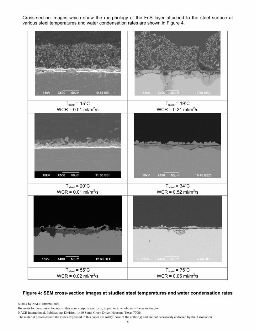
Cross-section images which show the morphology of the FeS layer attached to the steel surface at various steel temperatures and water condensation rates are shown in Figure 4.
Tsteel = 15˚C
WCR = 0.01 ml/m2/s
Tsteel = 19˚C
WCR = 0.21 ml/m2/s
Tsteel = 20˚C
WCR = 0.01 ml/m2/s
Tsteel = 34˚C
WCR = 0.52 ml/m2/s
Tsteel = 55˚C
WCR = 0.02 ml/m2/s
Tsteel = 75˚C
WCR = 0.05 ml/m2/s
Figure 4: SEM cross-section images at studied steel temperatures and water condensation rates
5
©2014 by NACE International. Requests for permission to publish this manuscript in any form, in part or in whole, must be in writing to NACE International, Publications Division, 1440 South Creek Drive, Houston, Texas 77084.The material presented and the views expressed in this paper are solely those of the author(s) and are not necessarily endorsed by the Association.

Generally, the FeS layer consists of two distinct layers attached to the steel. A two-step mechanism involving the rapid initial formation of a thin FeS layer, identified as mackinawite, on the metal surface which can be overlain by different phases of iron sulfide has been described by Smith.12 This two-step mechanism seems to be supported by the cross-sectional analyses performed in this study. Low temperatures between 15-19˚C (linked to higher condensation rate) seem to favor the formation of a very porous outer FeS layer. However, as the steel temperature increased (to greater than 20˚C), regardless of the condensation rate value, a more coherent and protective FeS layer was formed as evidenced by reduced TLC rates. Less pitting was also observed. The severity of the localized attack was high at a steel temperature 19°C but, overall, only a small fraction of the surface was affected by pitting. However, the mechanism of the occurrence of this pitting remains poorly understood.
The types and stabilities of the iron sulfides forming at the metal surface (such as mackinawite and pyrrhotite) is dependent on temperature, H2S partial pressure and pH.12 Various FeS morphologies were observed by SEM in the current work, as shown in Figure 5. The variety of observed morphologies is indicative of the different polymorphs of FeS formed on the steel surface. The steel temperature is also related to which FeS polymorph forms, and confers a degree of protection, to the metal surface. X-ray diffraction (XRD) analysis showed the presence of mackinawite, cubic FeS and troilite, depending on the gas/steel temperature. Explanations as to the occurrence of these particular iron sulfide corrosion products have been described by Smith.12 Mackinawite seems to be a dominant FeS phase as a corrosion product of mild steels as it is favored over a wide range of temperatures as well as it having rapid formation kinetics; faster than for any other FeS.13 The second FeS polymorph observed in the present work is known as cubic FeS. This is rarely observed due to its relative instability compared to other FeS phases. It is associated with high saturation levels with respect to FeS (i.e., high aqueous concentrations of Fe2+ ions) and moderate temperatures (35-50°C). Cubic FeS is hardly ever found at the bottom of the pipeline since its formation is inhibited by the presence of ions
such as Cl.14 Thus, it would be more readily found at the top of the pipeline in a cooler condensed water environment, free from chloride or other anions, which represents an ideal condition for its formation. Due to its relative instability versus other FeS polymorphs, cubic FeS can quickly transition into a more stable phase such as pyrrhotite. The third common type of FeS phase found in the studied sour TLC environment is known as troilite, its formation has been previously described by Singer,et al. 3 Troilite, which is the stochiometric end-member of the pyrrhotite (Fe1-xS) series, has a characteristic elongated morphology. Due to its solubility behavior, its occurrence is favored in more acidic solutions but has slower formation kinetics than for mackinawite. Thus, to promote the formation of troilite, a combination of higher temperature, lower pH and higher pH2S is required. Due to the wide range of steel temperatures tested in this study (15˚C to 75˚C), mackinawite and cubic FeS were identified to be the most dominant polymorphs. This could be explained by the lower steel temperature, due to high water condensation rate, which does not favor kinetically slow reactions, i.e., troilite formation. However, at a gas temperature of 80◦C and steel temperature of 75°C, corresponding to the highest studied temperature and a low condensation rate, the presence of troilite was confirmed by XRD analysis. In this condition, higher gas temperature which leads to higher steel temperature logically facilitates the formation of troilite.
6
©2014 by NACE International. Requests for permission to publish this manuscript in any form, in part or in whole, must be in writing to NACE International, Publications Division, 1440 South Creek Drive, Houston, Texas 77084.The material presented and the views expressed in this paper are solely those of the author(s) and are not necessarily endorsed by the Association.

Tgas = 25˚C
Tsteel= 20˚C
mackinawite, cubic FeS
Tsteel = 15˚C
mackinawite, cubic FeS
Tgas = 40˚C
Tsteel = 35˚C
mackinawite, cubic FeS
Tsteel = 22˚C
mackinawite, cubic FeS
7
©2014 by NACE International. Requests for permission to publish this manuscript in any form, in part or in whole, must be in writing to NACE International, Publications Division, 1440 South Creek Drive, Houston, Texas 77084.The material presented and the views expressed in this paper are solely those of the author(s) and are not necessarily endorsed by the Association.

Tgas = 60˚C
Tsteel = 55˚C
mackinawite, cubic FeS
Tsteel = 19˚C
mackinawite, cubic FeS
Tgas = 80˚C
Tsteel = 75˚C
mackinawite, cubic FeS, troilite
Tsteel = 34˚C
mackinawite, cubic FeS
Figure 5: SEM images and XRD patterns of FeS polymorphs at studied conditions
8
©2014 by NACE International. Requests for permission to publish this manuscript in any form, in part or in whole, must be in writing to NACE International, Publications Division, 1440 South Creek Drive, Houston, Texas 77084.The material presented and the views expressed in this paper are solely those of the author(s) and are not necessarily endorsed by the Association.

CONCLUSIONS
The following conclusions can be made in relation to the effect of gas/steel temperature and water condensation rate on highly sour top of the line corrosion:
Uniform top of the line corrosion rate decreased with increasing gas/steel temperature.
Higher gas and steel temperature led to the formation of a more coherent FeS layer that conferred greater protectiveness.
A very dense and thin FeS layer was always present on the metal surface. In some conditions, low temperature with high water condensation rate, a second thicker but more porous outer layer was observed.
Mackinawite and cubic FeS were identified in the corrosion product layer at the top of the line in most of the conditions tested while troilite was observed at higher temperature (gas temperature of 80˚C and steel temperature 75˚C).
Water condensation rate did not have a strong effect on the corrosion rate. Consequently, it is believed that the primary effect of water condensate is to lower the steel temperature.
ACKNOWLEDGEMENTS
The authors thank Prof. Srdjan Nesic for his comments and advice relating to this research. The authors would also like to acknowledge the financial support from the following companies and organizations: BP, Chevron, ConocoPhillips, ENI, PTTEP, Saudi Aramco, Total, OXY, Universiti Teknologi MARA and Ministry of Higher Education Malaysia.
REFERENCES
1. M. Estavoyer, "Corrosion Problems at Lacq Sour Gas Field in H2S Corrosion in Oil & Gas Production," CORROSION/1981, (Houston, TX,: NACE International, 1981).
2. N. Bich and K. Szklarz, "Crossfield Corrosion Experience," CORROSION/1988,(Houston,
TX:NACE International,1988). 3. M. Singer, A. Camacho, B. Brown and S. Nesic, "Sour Top of Line Corrosion in The Presence of
Acetic Acid," CORROSION/2010, paper no. 10100 (Houston, TX: NACE International, 2010). 4. D. Pugh, S. Asher, J. Cai and W. Sisak, "Top Of Line Corrosion Mechanism for Sour Wet Gas
Pipelines," CORROSION/2009, paper no. 09285 (Houston, TX: NACE International, 2009). 5. R. Nyborg and A. Dugstad, "Top of Line Corrosion and Water Condensation Rates in Wet Gas
Pipelines," CORROSION/2007, paper no. 07555 (Houston, TX: NACE International, 2007). 6. Z. Zhang, D. Hinkson, M. Singer, H. Wang and S. Nesic, "A Mechanistic Model of Top of Line
Corrosion," Corrosion Science, vol. 63, no. 11, pp. 1051-1062, 2007. 7. Y. Gunaltun and D. Larrey, "Correlation of Cases of Top of Line Corrosion with Calculated Water
Condensation Rate," CORROSION/2000, paper no. 00071 (Houston, TX: NACE International, 2000).
9
©2014 by NACE International. Requests for permission to publish this manuscript in any form, in part or in whole, must be in writing to NACE International, Publications Division, 1440 South Creek Drive, Houston, Texas 77084.The material presented and the views expressed in this paper are solely those of the author(s) and are not necessarily endorsed by the Association.

8. M. Singer, S. Nesic, D. Hinkson, Z. Zhang and H. Wang, "CO2 Top of the Line Corrosion in Presence of Acetic Acid-A Parametric Study," CORROSION/2009, paper no. 09292 (Atlanta, GA:NACE International, 2009).
9. H. Sun, H. Fang, J. Davis and R. Hudgins, "Elemental Sulfur Corrosion and Inhibition in the
Presence of Sulfur Solvent," CORROSION/2011, paper no. 11125 (Houston, TX: NACE International, 2011).
10. A. Camacho, M. Singer, B. Brown and S. Nesic, "Top of the Line Corrosion in H2S/CO2
Environments," CORROSION/2008, paper no. 08470 (New Orleans, LA: NACE International, 2008).
11. ASTM G1‐03, “Standard practice for preparing, cleaning and evaluating corrosion test specimens”, ASTM, Philadelphia, PA, pp.17‐23, 2009.
12. S. N. Smith, B. Brown and W. Sun, "Corrosion at Higher Concentrations and Moderate
Temperatures," CORROSION/2011, paper no. 11081 (Houston, TX: NACE International, 2011). 13. D. Shoesmith, P. Taylor, D. Bailey and D. Owen, "The Formation of Ferrous Monosulfide
Polymorph During the Corrosion of Iron by Aqueous Hydrogen Sulfide at 21˚C," Journal of the Electrochemical Society, vol. 127, no. 5, pp. 1007-1015, 1980.
14. J. B. Murowchick and H. Barnes, "Formation of Cubic FeS," Am. Mineralogist, vol. 71, pp. 1243-
1246, 1986.
10
©2014 by NACE International. Requests for permission to publish this manuscript in any form, in part or in whole, must be in writing to NACE International, Publications Division, 1440 South Creek Drive, Houston, Texas 77084.The material presented and the views expressed in this paper are solely those of the author(s) and are not necessarily endorsed by the Association.