paper no. 2
TRANSCRIPT

1 INTRODUCTION An efficient seismic force resisting system should possess enough strength such that member forces are lower than the factored resistance, supply adequate stiffness to limit the system’s deformation, and should exhibit sufficient ductility. Thus, concentri-cally braced frames (CBF) are characterized by a very high stiffness-to-weight ratio and limited ductil-ity. As stated in the Canadian standard CSA/S16-2009, the dissipative zones of the classical CBF sys-tems are located in the brace members which are de-signed to yield in tension and buckle in compression. However, during the hysteresis response, braces on the verge of buckling lose their buckling strength and drive the system to behave asymmetrically.
To overcome this deficiency, authors relayed on the statement given in Eurocode 8, where it is sug-gested that the location of dissipative zones may be placed in “the structural members or in the connec-tions”. In addition, it is stated that “the overstrength condition for connections need not apply if the con-nections are designed to contribute significantly to the energy dissipation capability” of the system. Thus, in this paper, a CBF system with dissipative single-pin brace-to-column connections is consi-dered for seismic simulation and design.
Initially, this innovative structural system was proposed and experimentally tested during the Euro-pean INERD project (Plumier et al. 2005). The sin-gle-pin connection consists of two outer-plates welded or bolted to the flanges of CBF’s columns, two inner-plates welded to the brace member and a single-pin running through the four plates as shown in Figure 1a. The dissipative zone is located in the pin, which yields in bending, while the remaining
connection components are designed to respond in elastic range. Thus, under earthquake loads, braced frames equipped with dissipative pin connections al-low braces to develop their full compressive strength and are able to avoid an asymmetrical response. In addition, when dissipative zones are located in the connections, adjacent members shall be designed with sufficient overstrength, to allow the develop-ment of cyclic yielding of the pin.
To emphasize the seismic response of low-rise CBF buildings with dissipative connections, a 2-storey structure located in a high risk seismic zone was selected and analysed against a limited ductile CBF system, by means of the OpenSees framework.
2 OPENSEES MODEL AND DESIGN OF CBF SYSTEM EQUIPPED WITH PIN DEVICES
2.1 Preliminary design of single-pin device
The behavior of the single-pin connection, corres-pondingly, its capacity to dissipate energy is influ-enced by the length of the pin, L, its cross-sectional size and shape as well as the distance between the inner-plates (L-2a) as illustrated in Figure 1b. Re-garding the shape of the pin, researchers have con-cluded that a rounded pin can resist larger forces due to a reduced effect of torsion, while a rectangular pin with rounded corners possesses a larger moment of inertia (Vayas & Thanopoulos 2005). Concerning the distance between the inner-plates (L-2a), it was concluded that the maximum energy is dissipated when a larger distance is provided. However, this configuration depends on the size and depth of the column’s cross-section, which governs the pin’s length. The pin behaves as a four-point loaded beam.
Seismic Simulation and Design of Low-Rise CBF Buildings with and without Dissipative Connections using OpenSees
L.Tirca, C. Caprarelli and N. Danila Dept. of Building, Civil and Environmental Eng., Concordia University, Montreal, Canada
ABSTRACT: In this study, the performance of a low-rise CBF building with dissipative single-pin connec-tions is analysed against the classical CBF building with limited ductility. The two seismic resistant braced frames located in Victoria, B.C., Canada, were modeled using the OpenSees framework. From the time-history analysis, it is concluded: CBFs with pin connections experience a longer fundamental period, develop approximately half of the classical CBF’s base shear, exhibit similar interstorey drift and higher ductility.

The axial tension/ compression force developed in the brace, P is transferred to the pin through two-point loads located at the intersection of the inner-plates and the pin. When the yielding moment My = WyFy is reached, the pin starts to yield in bending under the point load Py/2 = My/a. At this stage, cha-racterized by the yielding of the extreme fibers of the pin’s cross-section, the static deflection of the pin is:
δy = (My/6EI)aL(3 - 4aL) (1) where EI is the flexural stiffness, Wy is the section modulus and Fy is the yield strength of the pin. Figure 1. Single-pin connection: a) a 3-D view of the single-pin
brace-to-column connection; b) Pin member and its geometry.
By considering the small deflection theory, the
pin’s deflection at strain hardening is δsh =fa, where f is the plastic rotation. By definition, f = kstlp, where kst is the curvature at strain hardening com-puted as kst = 2εsh /h and lp is the length of the plastic hinge which may be approximated with the height of the pin’s cross-section, h. In general, the average strain hardening is estimated as: εsh = 10εy, where εy is the strain at yield. Therefore, the pin reaches its plastic moment Mp = WpFy under the two point- loads Pp/2. The maximum value of the total force is given in Eq. (2), while the corresponding deforma-tion is shown in Eq. (3).
PI = Pp = 2Mp/a (2) δI = (kstlp)a = (20εy)a (3) After the attainment of Mp, under the tow point-loads, same clamping is developed at the pin’s ends and end bending moment is generated (Fig. 2a). By equating the external work Pδ/2 = Pfa/2 with the internal work (M1 +M2)f, the ultimate load of the beam is given in Eq. 4. Herein, Mu = WpFu is the ul-timate flexural capacity of the pin computed with the steel yielding strength Fu. PII = Pu = 2(M1 +M2)/a ~ 4Mu/a (4) Under the two-point forces Pu/2, the ultimate strain εu is estimated as being approximately equal to εu= 0.1, the corresponding value of the ultimate plastic rotation fu becomes fu= 0.2 radians and the esti-mated ultimate deflection is:
δII = δu = 1.15(0.2a) (5) In Eq. (5), the numerical coefficient 1.15 symbolises the difference between the length of the plastic hinge lp and the dimension of the pin’s cross-section, h. The above equations have been derived and vali-dated against experimental test results provided by Plumier et al. (2005). By employing Eqs. (2) to (5), the pin response follows a tri-linear curve, which is shown in Figure 2b. The slope of the first segment defines the elastic modulus of elasticity E, while the second slop defines the tangent modulus, Et.
Figure 2. Pin response: a) Pin mechanism; b) Tri-linear curve.
Furthermore, the ultimate deformation of the pin influences the interstorey drift of the structure which is limited by the current NBCC code to be 2.5%hs, where hs is the storey height. When a brace is equipped with dissipative single-pin connections at both ends, the diagonal line will elongate with two times the ultimate pin deformation estimated at 2δu = 2[1.15(0.2a)]. The horizontal projection of the ul-timate pin deformation is Δ = 2δu/cosϕ where ϕ is the angle between the brace member and a horizon-tal line. To ensure that the lateral drift is less than 2.5%hs, the following equation must be satisfied: 2δu/cosϕ < 2.5%hs. It is implied that the distance be-tween the outer-plate and the inner-plate, a, should be in agreement with the following equation:
a < 0.054hscosϕ (6) Therefore, the pin should be calibrated to satisfy both strength and deformability criteria. Regarding strength, the pin should resist the axial force devel-oped in the brace and be design to yield before the brace reaches 80% of its compressive strength. With regards to deformability, Eq. (6) must be satisfied.
2.2 OpenSees model
The OpenSees pin model, shown in Figure 3, was built to simulate the behavior of a four-point loaded beam, as previously described, and demonstrated the seismic response of the pin member. It consists of eight nonlinear beam-column elements and four in-tegration points per element. The pin’s cross-section is made up of 60 fibers. Among them, 12 fibers were
a) b) a) b)

-80 -40 0 40 80Displace m ent [m m ]
-800
-400
0
400
800
Force [k N]
Ex pe rimenta l res ult
Pinchin g
Sk elet on curve
assigned along the depth of the cross-section and 5 along its width. The length of the pin, Lpin is the clear span between the outer-plates which act as supports. Herein, the pin’s supports are modeled as rigid links with a length equal to the thickness of the outer-plate, top. To allow rotation between the pin member and the support (rigid link), a zero-length rotational spring is added at both ends. The material assigned to the pin model is Steel02 which is known also as Giuffre-Menegotta-Pinto material. A cali-brated Pinching4 material, explained below, is as-signed to springs and rigid links to simulate the de-formation of the pin in the outer-plate supports. In this pin model a very small strain hardening value of 0.0005 was considered. The computations con-ducted for a 40x60mm pin member, made up of steel with the following properties: Fy=396MPa and Fu= 558MPa, are detailed in Tirca et al. (2011).
Figure 3. OpenSees pin model.
As mentioned above, the Pinching4 material was
calibrated against experimental data obtained from a full scale single-storey CBF frame in X-bracing con-figuration, where braces were equipped with single-pin brace-to-column connections at both their ends. The experimental test was conducted at Polytechnic of Milano, while the OpenSees model simulated by authors is shown in Figure 4. In this regard, beams and columns are modeled using one beam-with-hinge element per member and the length of the plastic hinge was set to be equal to the depth of the member. Each column cross-section was defined as fiber section with 5 fibers along the flange width and 6 fibers along the depth of the web. The beam was connected to the column with a zero-length rotation-al spring, C1. Each of the four brace segments were modeled with 8 nonlinear beam-column elements and 4 integration points per element. As per the aforementioned figure, the tensile brace was defined to work as one element using 16 sub-elements and the compressive brace was defined as two half-brace connected to the tensile brace by very stiff rotational springs, C4. In the experimental test, W-shape was used for all members including braces. The cross-section of each brace was defined with 5 fibers along the flange width and 6 fibers along the web’s depth. A section aggregator was used to assign a torsional stiffness to each cross-section of brace. In order to connect braces to columns, 4 rigid links, defined as elastic beam-columns were used. These rigid links represent the part of the brace, or brace connectors (outer-plates) that are rigidly fas-tened to the column. A zero-length spring element
was inserted between the end node of the brace and the rigid link. The properties of these springs C2 and C3 were set for two different situations: one was to model the single-pin connection and the other was to model a gusset plate. In the case of modeling the gusset plate, stiffer properties were set in order to simulate its rigid behaviour. The Giuffré-Menegotta-Pinto material was assigned to all members.
Figure 4. OpenSees model of a CBF system with pin devices. The pin connection, represented by zero-length
elements deforming in x and y translations, was de-fined using the Pinching4 material. The pinching that is exhibited is the loss of resistance during un-loading of the pin after a tensile force was applied and reloading it after the point force has changed di-rection. As shown below in Figure 5, a skeleton curve was built to encompass the total force defor-mation shape, where the displacement accounts for two pins located at the ends of each brace.
Figure 5. Calibration of the Pinching4 material.
The three points defined in the skeleton curve
represent the tri-linear curve of the pin stiffness as discussed in Fig. 2b. The first slope would define the elastic stiffness of the pin while the second slope de-fines the plastic stiffness and the third represents some overstrength of material. The pinched shape of the curve is defined by specifying three floating point values in tension and three floating point val-ues in compression. The first floating point value, both in tension and compression is defined by the ra-tio of the deformation at the point of reloading to the total hysteretic deformation demand. The second
floating point value, again in both tension and com-pression, is the ratio of the force at the point of re-loading to the force corresponding to the total hyste-retic deformation demand. The third floating point value is a ratio of the strength developed upon un-loading to the maximum strength developed in the monotonic loading stage.
3 NUMERICAL ANALYSES
3.1 Design and analytical procedure
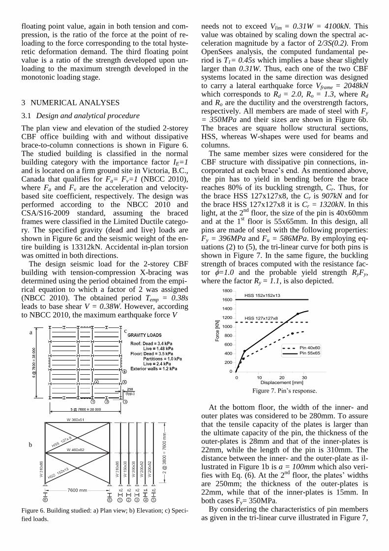
The plan view and elevation of the studied 2-storey CBF office building with and without dissipative brace-to-column connections is shown in Figure 6. The studied building is classified in the normal building category with the importance factor IE=1 and is located on a firm ground site in Victoria, B.C., Canada that qualifies for Fa= Fv=1 (NBCC 2010), where Fa and Fv are the acceleration and velocity-based site coefficient, respectively. The design was performed according to the NBCC 2010 and CSA/S16-2009 standard, assuming the braced frames were classified in the Limited Ductile catego-ry. The specified gravity (dead and live) loads are shown in Figure 6c and the seismic weight of the en-tire building is 13312kN. Accidental in-plan torsion was omitted in both directions.
The design seismic load for the 2-storey CBF building with tension-compression X-bracing was determined using the period obtained from the empi- rical equation to which a factor of 2 was assigned (NBCC 2010). The obtained period Temp = 0.38s leads to base shear V = 0.38W. However, according to NBCC 2010, the maximum earthquake force V
Figure 6. Building studied: a) Plan view; b) Elevation; c) Speci-
fied loads.
needs not to exceed Vlim = 0.31W = 4100kN. This value was obtained by scaling down the spectral ac-celeration magnitude by a factor of 2/3S(0.2). From OpenSees analysis, the computed fundamental pe-riod is T1= 0.45s which implies a base shear slightly larger than 0.31W. Thus, each one of the two CBF systems located in the same direction was designed to carry a lateral earthquake force Vframe = 2048kN which corresponds to Rd = 2.0, Ro = 1.3, where Rd and Ro are the ductility and the overstrength factors, respectively. All members are made of steel with Fy = 350MPa and their sizes are shown in Figure 6b. The braces are square hollow structural sections, HSS, whereas W-shapes were used for beams and columns. The same member sizes were considered for the CBF structure with dissipative pin connections, in-corporated at each brace’s end. As mentioned above, the pin has to yield in bending before the brace reaches 80% of its buckling strength, Cr. Thus, for the brace HSS 127x127x8, the Cr is 907kN and for the brace HSS 127x127x8 it is Cr = 1320kN. In this light, at the 2
nd floor, the size of the pin is 40x60mm
and at the 1st floor is 55x65mm. In this design, all
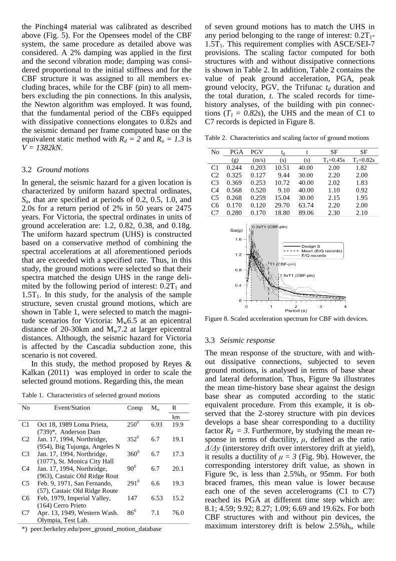
pins are made of steel with the following properties: Fy = 396MPa and Fu = 586MPa. By employing eq-uations (2) to (5), the tri-linear curve for both pins is shown in Figure 7. In the same figure, the buckling strength of braces computed with the resistance fac-tor =1.0 and the probable yield strength RyFy, where the factor Ry = 1.1, is also depicted.
Figure 7. Pin’s response.
At the bottom floor, the width of the inner- and outer plates was considered to be 280mm. To assure that the tensile capacity of the plates is larger than the ultimate capacity of the pin, the thickness of the outer-plates is 28mm and that of the inner-plates is 22mm, while the length of the pin is 310mm. The distance between the inner- and the outer-plate as il-lustrated in Figure 1b is a = 100mm which also veri-fies with Eq. (6). At the 2
nd floor, the plates’ widths
are 250mm; the thickness of the outer-plates is 22mm, while that of the inner-plates is 15mm. In both cases Fy= 350MPa.
By considering the characteristics of pin members as given in the tri-linear curve illustrated in Figure 7,
a
)
c
)
b
)
the Pinching4 material was calibrated as described above (Fig. 5). For the Opensees model of the CBF system, the same procedure as detailed above was considered. A 2% damping was applied in the first and the second vibration mode; damping was consi-dered proportional to the initial stiffness and for the CBF structure it was assigned to all members ex-cluding braces, while for the CBF (pin) to all mem-bers excluding the pin connections. In this analysis, the Newton algorithm was employed. It was found, that the fundamental period of the CBFs equipped with dissipative connections elongates to 0.82s and the seismic demand per frame computed base on the equivalent static method with Rd = 2 and Ro = 1.3 is V = 1382kN.
3.2 Ground motions
In general, the seismic hazard for a given location is characterized by uniform hazard spectral ordinates, Sa, that are specified at periods of 0.2, 0.5, 1.0, and 2.0s for a return period of 2% in 50 years or 2475 years. For Victoria, the spectral ordinates in units of ground acceleration are: 1.2, 0.82, 0.38, and 0.18g. The uniform hazard spectrum (UHS) is constructed based on a conservative method of combining the spectral accelerations at all aforementioned periods that are exceeded with a specified rate. Thus, in this study, the ground motions were selected so that their spectra matched the design UHS in the range deli-mited by the following period of interest: 0.2T1 and 1.5T1. In this study, for the analysis of the sample structure, seven crustal ground motions, which are shown in Table 1, were selected to match the magni-tude scenarios for Victoria: Mw6.5 at an epicentral distance of 20-30km and Mw7.2 at larger epicentral distances. Although, the seismic hazard for Victoria is affected by the Cascadia subduction zone, this scenario is not covered.
In this study, the method proposed by Reyes & Kalkan (2011) was employed in order to scale the selected ground motions. Regarding this, the mean Table 1. Characteristics of selected ground motions
*) peer.berkeley.edu/peer_ground_motion_database
of seven ground motions has to match the UHS in any period belonging to the range of interest: 0.2T1- 1.5T1. This requirement complies with ASCE/SEI-7 provisions. The scaling factor computed for both structures with and without dissipative connections is shown in Table 2. In addition, Table 2 contains the value of peak ground acceleration, PGA, peak ground velocity, PGV, the Trifunac td duration and the total duration, t. The scaled records for time-history analyses, of the building with pin connec-tions (T1 = 0.82s), the UHS and the mean of C1 to C7 records is depicted in Figure 8. Table 2. Characteristics and scaling factor of ground motions
Figure 8. Scaled acceleration spectrum for CBF with devices.
3.3 Seismic response
The mean response of the structure, with and with-out dissipative connections, subjected to seven ground motions, is analysed in terms of base shear and lateral deformation. Thus, Figure 9a illustrates the mean time-history base shear against the design base shear as computed according to the static equivalent procedure. From this example, it is ob-served that the 2-storey structure with pin devices develops a base shear corresponding to a ductility factor Rd = 3. Furthermore, by studying the mean re-sponse in terms of ductility, μ, defined as the ratio Δ/Δy (interstorey drift over interstorey drift at yield), it results a ductility of μ = 3 (Fig. 9b). However, the corresponding interstorey drift value, as shown in Figure 9c, is less than 2.5%hs or 95mm. For both braced frames, this mean value is lower because each one of the seven accelerograms (C1 to C7) reached its PGA at different time step which are: 8.1; 4.59; 9.92; 8.27; 1.09; 6.69 and 19.62s. For both CBF structures with and without pin devices, the maximum interstorey drift is below 2.5%hs, while
No Event/Station Comp Mw R
km
C1 Oct 18, 1989 Loma Prieta, (739)*, Anderson Dam
2500 6.93 19.9
C2 Jan. 17, 1994, Northridge, (954), Big Tujunga, Angeles N
3520 6.7 19.1
C3 Jan. 17, 1994, Northridge, (1077), St. Monica City Hall
3600 6.7 17.3
C4 Jan. 17, 1994, Northridge, (963), Castaic Old Ridge Rout
900 6.7 20.1
C5 Feb. 9, 1971, San Fernando, (57), Castaic Old Ridge Route
2910 6.6 19.3
C6 Feb, 1979, Imperial Valley, (164) Cerro Prieto
147 6.53 15.2
C7 Apr. 13, 1949, Western Wash. Olympia, Test Lab.
860 7.1 76.0
No PGA PGV td t SF SF
(g) (m/s) (s) (s) T1=0.45s T1=0.82s
C1 0.244 0.203 10.51 40.00 2.00 1.82
C2 0.325 0.127 9.44 30.00 2.20 2.00 C3 0.369 0.253 10.72 40.00 2.02 1.83 C4 0.568 0.520 9.10 40.00 1.10 0.92 C5 0.268 0.259 15.04 30.00 2.15 1.95 C6 0.170 0.120 29.70 63.74 2.20 2.00 C7 0.280 0.170 18.80 89.06 2.30 2.10
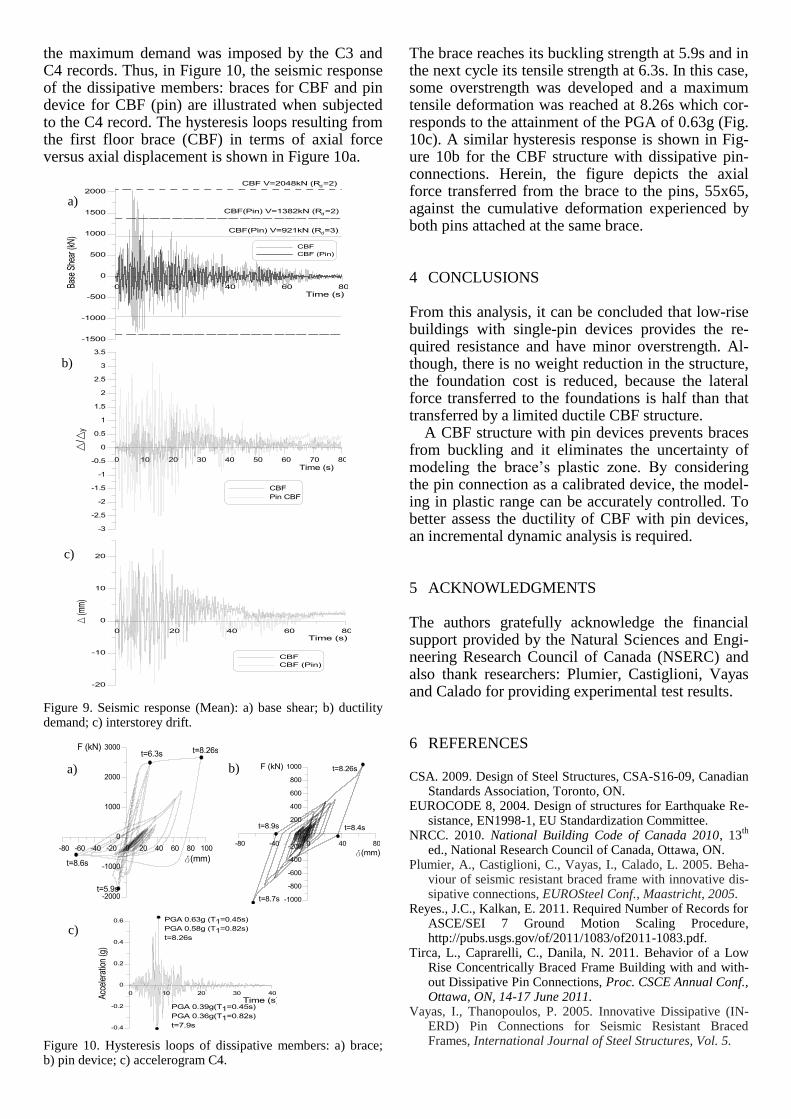
the maximum demand was imposed by the C3 and C4 records. Thus, in Figure 10, the seismic response of the dissipative members: braces for CBF and pin device for CBF (pin) are illustrated when subjected to the C4 record. The hysteresis loops resulting from the first floor brace (CBF) in terms of axial force versus axial displacement is shown in Figure 10a. Figure 9. Seismic response (Mean): a) base shear; b) ductility demand; c) interstorey drift. Figure 10. Hysteresis loops of dissipative members: a) brace; b) pin device; c) accelerogram C4.
The brace reaches its buckling strength at 5.9s and in the next cycle its tensile strength at 6.3s. In this case, some overstrength was developed and a maximum tensile deformation was reached at 8.26s which cor-responds to the attainment of the PGA of 0.63g (Fig. 10c). A similar hysteresis response is shown in Fig-ure 10b for the CBF structure with dissipative pin-connections. Herein, the figure depicts the axial force transferred from the brace to the pins, 55x65, against the cumulative deformation experienced by both pins attached at the same brace.
4 CONCLUSIONS From this analysis, it can be concluded that low-rise buildings with single-pin devices provides the re-quired resistance and have minor overstrength. Al-though, there is no weight reduction in the structure, the foundation cost is reduced, because the lateral force transferred to the foundations is half than that transferred by a limited ductile CBF structure.
A CBF structure with pin devices prevents braces from buckling and it eliminates the uncertainty of modeling the brace’s plastic zone. By considering the pin connection as a calibrated device, the model-ing in plastic range can be accurately controlled. To better assess the ductility of CBF with pin devices, an incremental dynamic analysis is required.
5 ACKNOWLEDGMENTS
The authors gratefully acknowledge the financial support provided by the Natural Sciences and Engi-neering Research Council of Canada (NSERC) and also thank researchers: Plumier, Castiglioni, Vayas and Calado for providing experimental test results.
6 REFERENCES
CSA. 2009. Design of Steel Structures, CSA-S16-09, Canadian Standards Association, Toronto, ON.
EUROCODE 8, 2004. Design of structures for Earthquake Re-sistance, EN1998-1, EU Standardization Committee.
NRCC. 2010. National Building Code of Canada 2010, 13th
ed., National Research Council of Canada, Ottawa, ON.
Plumier, A., Castiglioni, C., Vayas, I., Calado, L. 2005. Beha-viour of seismic resistant braced frame with innovative dis-sipative connections, EUROSteel Conf., Maastricht, 2005.
Reyes., J.C., Kalkan, E. 2011. Required Number of Records for ASCE/SEI 7 Ground Motion Scaling Procedure, http://pubs.usgs.gov/of/2011/1083/of2011-1083.pdf.
Tirca, L., Caprarelli, C., Danila, N. 2011. Behavior of a Low Rise Concentrically Braced Frame Building with and with-out Dissipative Pin Connections, Proc. CSCE Annual Conf., Ottawa, ON, 14-17 June 2011.
Vayas, I., Thanopoulos, P. 2005. Innovative Dissipative (IN-ERD) Pin Connections for Seismic Resistant Braced Frames, International Journal of Steel Structures, Vol. 5.
a) b)
c)
a)
b)
c)