paper a novel energy absorber based on magnetorheological gel...
TRANSCRIPT

Smart Materials and Structures
PAPER
A novel energy absorber based on magnetorheological gelTo cite this article: Haoming Pang et al 2017 Smart Mater. Struct. 26 105017
View the article online for updates and enhancements.
This content was downloaded from IP address 218.22.21.14 on 12/09/2017 at 16:05

A novel energy absorber based onmagnetorheological gel
Haoming Pang, Shouhu Xuan, Chuanlin Sun and Xinglong Gong
CAS Key Laboratory of Mechanical Behavior and Design of Materials, Department of Modern Mechanics,University of Science and Technology of China (USTC), Hefei 230027, People’s Republic of China
E-mail: [email protected]
Received 19 May 2017, revised 15 July 2017Accepted for publication 1 August 2017Published 12 September 2017
AbstractIn this work, a novel magnetorheological energy absorber (MREA) was designed by usingmagnetorheological gel (MRG) as the damping medium. The proposed MREA had tunablepiston gap distances and variable inner magnetic flux density distribution. The piston gapdistance could be varied from 7–2 mm and the magnetic flux density at the gap increased from120–860 mT, respectively. Under both low velocity compression and high speed impact, thedamping could be divided into three parts. In the impact test, the velocity of a drop hammercould be reduced from to 3.4–0 m s−1 within a very short time (13 ms) and distance (17 mm).The maximum damping force of the MREA reached to as high as 8 kN. The damping force couldalso be adjusted by changing the current input. Under a 2 A current, the energy absorption ratioincreased about 23% (from 4.13–5.07 J mm−1).
Keywords: energy absorber, magnetorheological gels, structure design, tunable piston gap,impact
(Some figures may appear in colour only in the online journal)
Introduction
A traditional energy absorber (EA) is designed to dissipateimpact energy and decrease injury, thus it has been widelyapplied in the railway industry and earthquake engineering[1, 2]. A magnetorheological energy absorber (MREA) is anadaptive energy absorber which can reversibly and rapidlyadjust the damping force by changing the current input [3–7].Different from the traditional passive energy absorber, thedamping mediums in MREAs are magnetorheological (MR)materials whose mechanical properties are sensitive to theexternal magnetic field. To this end, the MREAs are advan-tageous in many areas that require precise control.
The MREA is a specific MR damper designed for absorbingimpact energy. The damping medium in most of the previouslyreported MREAs was MR fluids [8–11]. MR fluids were usuallyprepared by dispersing micro-sized carbonyl iron particles intononmagnetic fluids. Under applying a magnetic field, the yieldstress of the MR fluid would be critically increased [12]. ManyMR dampers and MREAs filled with MR fluids have beenstudied [13–16]. Nguyen et al designed a linear stroke adaptiveMREA and tested the performance under intense impact
conditions [6, 17]. The maximum piston velocity was up to8m s−1 and the maximum damping force reached 15 kN. Maoet al proposed an MR damper with bi-fold valves for shockmitigation and used a nonlinear model to study the behaviorunder high speed impact conditions [18, 19]. Wereley et alanalyzed the shock mitigation capabilities of an MREA andestablished a semi-active shock isolation system based on theMR damper [20, 21]. An MR seat suspension model was alsoconstructed for military vehicles [22]. Hu et al proposed a newmethod to design high-performance MR dampers and MRvalves [23, 24]. They added MR elastomers on an MR fluiddamper to improve the stiffness variability and damping varia-bility. They also designed an MR damper with improved dis-placement differential self-induced ability. Sun et al added MRelastomerson an MR fluid damper to improve the stiffnessvariability and damping variability [25]. Among the aboveresearches, the MR fluid was used as the damping medium[26, 27] because the MR effect on MR fluids is high and theresponse time is short. However, the sealing, settlement anddurability problem in MR fluids have limited their practicalapplications. Moreover, Choi et al reported the temperature-dependent dynamic characteristics of a piezo-electric actuator
Smart Materials and Structures
Smart Mater. Struct. 26 (2017) 105017 (9pp) https://doi.org/10.1088/1361-665X/aa834c
0964-1726/17/105017+09$33.00 © 2017 IOP Publishing Ltd Printed in the UK1

under high temperature. They found that both the strain andblocking force were decreased with increasing the temper-ature [28, 29].
The MR gels were composed of carbonyl iron particlesand a polymer gel [30–33]. Due to the high viscosity ofpolymer gel, the MR gels had better stability than the MRfluids. Considering its high MR effect, MR gel was pro-spective in engineering applications such as MR vibrationabsorbers [34]. Unfortunately, few works have studied theperformance of an MREA filled with MR gels. One of themost important parameters of an MREA is the maximumdamping force. To improve the maximum damping force,increasing the viscosity of the damping medium is a directway. Using MR gel as the damping medium could increasethe damping force of an MREA and reduce the dampingdistance. On the one hand, the saturated magnetic field of anMR gel is large, thus the design of the electromagnet iscomplex. On the other hand, it is easy to generate a forcepulse in an MREA filled with high viscose damping mediumunder an impact. How to utilize the whole damping range isimportant for shock mitigation. Therefore, designing anMREA with high damping force, short distance, and adjus-table damping force is urgent.
This work reports a novel MREA in which an MR gel isused as the damping medium. To better control the dampingforce and make full use of the advantages of MR gel, the
damping gap distance of the MREA was designed to bedecreased as the piston was pressed down. The internalmagnetic flux density distribution was also simulated and themagnetic field dependent performance was analyzed. Finally,the damping forces of the MREA under low speed com-pression and high speed impact were studied.
Experimental details
Test system
The rheological properties of MR gel were tested by a com-mercial rheometer Physica MCR301 (produced by AntonPaar GmbH, Austria) equipped with an electro-magneticaccessory MRD180. An electromechanical universal testingmachine (Model 43, MTS System Corporation, China) wasused to test the mechanical properties under compression. Thebuffer performance of the MREA was tested on a drophammer test system (ZCJ1302-A, MTS System Corporation,China). The weight and height of the drop hammer weretunable and the acceleration signal of the hammer wasrecorded. During the test, the current input was controlled bya dc power supply (IT6724, Itech Electronics, Co., Ltd,China).
Figure 1. The mechanical properties of the MR gel (a). The shear viscosity of the MR gel under different magnetic fields, (b) the shear stresson the MR gels under different magnetic flux densities and different shear rates, (c) the compressive stress on the MR gel with differentsqueezing velocity under a squeeze mode and (d) the compressive force on the MR gel with different magnetic fields under a squeeze mode.
2
Smart Mater. Struct. 26 (2017) 105017 H Pang et al

Preparation and mechanical properties of MR gel
MR gel with 70 wt% carbonyl iron powders was prepared andused in the MREA. The materials used for the MR gel were:toluene diisocyanate (TDI, 2,4-TDI at ∼80%, 2,6-TDI at∼20%, Tokyo Chemical Industry Co. Ltd, Japan), poly-propylene glycol (PPG-1000, Sinopec Group Co. Ltd, China),1,4-Butanediol (BDO, Sinopharm Chemical Reagent Co.,Ltd, China), carbonyl iron powder (CIP, type CN, BASFAktiengesellschaft, Germany) and 1-methyl-2-pyrrolidone(Sinopharm Chemical Reagent Co., Ltd, China). Firstly, TDIand PPG were added to a flask with the molar ratio 3:1 at80 °C for 2 h. Their weights were calculated by the formulabellow:
m
m
174 mol
1000 mol3, 1TDI
1
PPG1
⋅⋅
=-
-( )/
/
where mTDI and mPPG represent the weight of PPG and TDI,respectively. Later the temperature of the mixture was low-ered to 60 °C and BDO was added into the reactor. The
weight of the BDO was calculated by the formula bellow:
mm m
174 mol
1000mol
90mol
1.1 , 2TDI1
PPG 1 BDO 1
⋅
⋅ + ⋅=
-
- -( )/
Figure 2. Schematic diagram, design parameters and photographs of the MREA with a tunable resistance gap: 1. Upper piston rod, 2. endcover, 3. coat, 4. exciting coil, 5. insulation lining, 6. piston, 7. nether piston rod.
Table 1. MREA design variables.
Parameter Value
Diameter of the rod d0 16 mmDiameter of the bottom piston edge d1 40 mmDiameter of the top piston edge d2 42 mmThickness of the piston h0 5 mmThickness of the exciting coil h1 30 mmInner diameter of the top insulation lining edge d4 56 mmInner diameter of the bottom insulation lining edge d3 44 mmDiameter of the insulation lining d5 60 mmDiameter of the exciting coil d6 80 mmDiameter of the coat d7 100 mm
3
Smart Mater. Struct. 26 (2017) 105017 H Pang et al

where mBDO represents the weight of the BDO. 40 min later,1-methyl-2-pyrrolidone was added into the mixture at a 10wt% ratio. Once the polymer gel was synthesized, the CIPswere added under vigorously mixing before the temperaturewas cooled down.
Obviously, the shear viscosity of the MR gel was highlydependent on the magnetic field, so the shear stress waschanged by a large range by applying the magnetic field(figure 1(b)). The shear stress increased with the increasing ofshear rate and it could be expressed as
k 30t t g= + ( )
In equation (3), t is the shear stress, 0t is the yield stressand is dependent on the magnetic field and 22 kPa0t = forthe MR gel under a 480 mT magnetic field. g represents theshear rate and k is the coefficient to be determined. Themechanical properties of MR gel under a squeeze mode werealso tested. The initial diameter of the sample was 20 mm andthe initial height was 6 mm. There was a fast increase in thecompressive force with decreasing the gap distance and thenthe sample was yielded. After a steady increase, the com-pressing force increased rapidly. So, the compression processcan be divided into three parts. When the strain was smallerthan 7%, the compressive force rapidly increased and the
sample began to yield. After that, the compressive forceincreased slowly until the diameter–height ratio reached about5, and the compressive stress quickly increased. The com-pressive stress was highly dependent on the magnetic field(figure 1(c)) and the compressive rate also had a strengtheninginfluence on the compressing force (figure 1(d)).
Design of the MREA
Structure analysis of the MREA
The structure of the MREA is shown in figure 2. The basiccomponents include: two piston rods, a piston, an insulationlining, an exciting coil, two end covers and a coat. MR gelwas filled into the cavity between the insulation lining, andthe end covers and an exciting coil was wrapped on theinsulation lining. Figure 2(b) shows the parameters of thecomponents and table 1 lists the values. The side of the pistonwas a slope and it was parallel to the inner face of the insu-lation lining, so the gap distance d decreased as the piston waspressed down. The maximum and minimum gap distancebetween the piston and the insulation lining were 7 mm and2 mm, respectively. The equation between the gap distance d
Figure 3. The magnetic flux density contour in the MREA with different piston positions. The displacement of the piston was 0 mm, 5 mm,10 mm and 20 mm, respectively.
4
Smart Mater. Struct. 26 (2017) 105017 H Pang et al

and the piston displacement h was d=7 − h/5. With thepiston moving down, the MR gel under the piston wassqueezed and flowed to space above the piston by the gap.The damping force was the sum of the shear force (worked onthe side of the piston) and the normal force (on the under-surface of the piston), thus the mechanical properties of MRgel under both a shear mode and squeeze mode had a biginfluence on the behavior of the MREA. When a constantdirect current was applied in the exciting coil, a closed loop ofmagnetic circuits would be generated in the coat, the endcovers, the upper piston rod, the piston, the resistance gap andthe space between the piston and the bottom end covers. Theend covers, the upper piston rod and the coat were made fromNo. 10 steel with high relative permeability and the netherpiston rod was made from stainless steel with low relativepermeability. The magnetic flux density in the gap changedwith the piston position and this characteristic also helpedadjust the energy dissipation process.
Simulation analysis of the magnetic field in the MREA
Since the mechanical properties of the MR gel were sensitiveto a magnetic field, the inner magnetic flux density wassimulated using ANSYS software. Figure 3 shows the
magnetic flux density contour in an axisymmetric 2D modelof the MREA. The upper piston rod, end cover, coat andpiston were made from low carbon steel whose permeabilitywas defined by the B-H curve in figure 4. The permeability ofthe MRG gel was also defined by the B-H curve. The netherpiston rod was made from stainless steel, the exciting coil iscopper and the insulation lining is aluminum with a relativepermeability of 1. The number of coil turns was 1100 and thecurrent was set as 2 A. Obviously, the magnetic flux densityboth under the piston and at the gap increased with the pistonmoving down, which meant the resistance force wouldincrease if the compression velocity of the piston was constant
Figure 5. The magnetic flux density in the gap and under the pistonwith different piston displacement.
Figure 6. The damping force and distribution of the magnetic fluxlines of the MREA as the piston was pressed down.
Figure 4. B-H curves of low carbon steel (a) and MRG with 70 wt% CIPs (b).
5
Smart Mater. Struct. 26 (2017) 105017 H Pang et al

(figure 5). It is useful for energy absorbing especially for shockmitigation under a shock. With the piston moving down, themagnetic flux density in the gap increased from 120–860mT.Generally, under a shock pulse, the velocity at the moment ofcontact was high and the resistance force was large because theshear force increased with the increasing of shear rate. To avoidthe force pulse, the gap distance of the proposed MREAdecreased as the piston was pressed down. So the shear rate waslow at the moment of contact and gradually increased with thepiston moving down. After the initial contact, the shock velocitywas slowed down and the gap distance decreased to generate arelatively large force. At this time, if there was a current appliedto the exciting coil, the magnetic flux density in the gap wouldincrease with the piston moving down. The viscosity of the MRgel increased which further helped mitigate the impact. So, theproposed design can adjust the energy absorbing process andimprove the utilization of the whole stroke.
Test results and discussion
Low velocity compression test
The low velocity compression test was carried out by aModulab material test system. A pedestal was fixed on the
end cover to support the MREA. A dc power was used tocontrol the current in the exciting coil of the MREA. Asshown in figure 6, the energy absorption process can bedivided into three parts. When the displacement was less than3 mm, there was an abrupt increase in the resistance forcebecause of the mechanical friction and the yield of the MRgel. This area was named the launched area. After that, thecompressive force increased gradually as the piston waspressed down under a constant velocity. The resistance forcewas mainly caused by the viscose flow of the MR gel in thegap. With the piston moving down, the gap distance ddecreased and the shear rate increased, so the viscose forceincreased. In addition, when there was a current in theexciting coil, the magnetic field was presented in the resist-ance gap. The simulation results demonstrated that themagnetic field was basically perpendicular to the gap. Themagnetic flux density in the gap increased with the pistonmoving down; thus, it further improved the force. With fur-ther increasing of the displacement (more than 17 mm), theMR gel under the piston was squeezed and the resistanceforce increased rapidly. The magnetic flux lines under thepiston were also vertical to the undersurface of the piston,which was useful for the MR gel to produce a large normalforce with the current input. The rapidly increased force couldavoid the contact of the piston and the end cover. In other
Figure 7. Resistance force of the MREA under different current and different compression velocity, (a) with a changing current, (b) underdifferent compression velocity without current, (c) with different currents and a 0.2 mm s−1 compression velocity and (d) with differentcurrents and a 1.0 mm s−1 compression velocity.
6
Smart Mater. Struct. 26 (2017) 105017 H Pang et al

words, the resistance force increased as the piston was presseddown during the entire process. When the compressionvelocity was constant, it was useful to counteract the pulseforce caused by the impact. The resistance force could also bechanged in a large range by applying a current to the excitingcoil (figures 7(a)–(d)) and it was highly dependent on thecompression velocity (figure 7(b)). Here, the compressiveforce increased from 17–171 N with the current increasingfrom 0–2 A.
Drop hammer test of MREA
The drop hammer test system was built to evaluate the shockmitigation capabilities of the MREA (figure 8). The MREAwas fixed on the substrate of the drop hammer test system andthe current input was controlled by dc power. During the drophammer testing, an acceleration sensor was fixed on the drophammer and the signal was converted by a signal-amplifierand recorded with an oscilloscope. The acceleration signal ofthe hammer was recorded during the impact. The force on thehammer could be calculated by Newton’s second law. Thehammer struck the piston rod then the force on the piston rodwas equal to the force on the hammer. The change in thevelocity was calculated by integrating the acceleration signaland the displacement was calculated by integrating the velo-city. As shown in figure 9, there was an abrupt increase in theimpact force at the moment of contact. The resistance forcedecreased after the abrupt increase because the MR gel yiel-ded and then rebounded in the MREA. At the displacement of5 mm, the force reached the maximum but did not drop
rapidly. Until the displacement reached16 mm, the resistancedecreased rapidly. So, the whole stroke of the proposedMREA was thoroughly used to mitigate the shock and avoidthe force pulse. Due to the friction between the hammer andthe track, the maximum speed of the piston was less than thefree fall speed of the hammer. The velocity of the piston wasreduced from 3.4–0 m s−1 in 13 ms with a 17 mm distance.Combining equation (3), we can get the viscous resistanceforce:
F s ks , 4t g= = ( )
where F represents the viscous resistance force and s is theside area of the piston and g represents the shear rate. In theviscose flow area, the velocity reduced from 2.8–0.8 m s−1
(decreased 70%) but the force decreased from 6–4 kN(decreased 33%). That was because the gap distance d alsoreduced with the decreasing of the velocity, which sloweddown the decrease of the shear rate. At the last 2 mm, thepiston was close to the end cover and the velocity of thepiston dropped rapidly. The absorbed energy evenly rosewhich met the design expectations.
To further test the shock mitigation capabilities of theMREA, drop hammers with different weights were droppedfrom different heights. The tendency of the force curves with
Figure 8. Drop hammer test rig of the MREA.
Figure 9. The load-stroke profile of MREA. The weight of the drophammer was 16 kg and the height was 80 cm.
7
Smart Mater. Struct. 26 (2017) 105017 H Pang et al
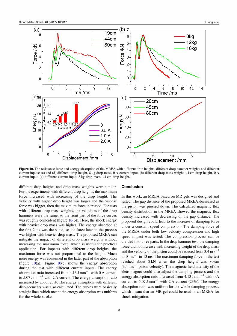
different drop heights and drop mass weights were similar.For the experiments with different drop heights, the maximumforce increased with increasing of the drop height. Thevelocity with higher drop height was larger and the viscoseforce was bigger, then the maximum force increased. For testswith different drop mass weights, the velocities of the drophammers were the same, so the front part of the force curveswas roughly coincident (figure 10(b)). Here, the shock energywith heavier drop mass was higher. The energy absorbed atthe first 2 ms was the same, so the force later in the processwas higher with heavier drop mass. The proposed MREA canmitigate the impact of different drop mass weights withoutincreasing the maximum force, which is useful for practicalapplication. For impacts with different drop heights, themaximum force was not proportional to the height. Muchmore energy was consumed in the latter part of the absorption(figure 10(a)). Figure 10(c) shows the energy absorptionduring the test with different current inputs. The energyabsorption ratio increased from 4.13 J mm−1 with 0 A currentto 5.07 J mm−1 with 2 A current. The energy absorption ratioincreased by about 23%. The energy absorption with differentdisplacements was also calculated. The curves were basicallystraight lines which meant the energy absorption was uniformfor the whole stroke.
Conclusion
In this work, an MREA based on MR gels was designed andtested. The gap distance of the proposed MREA decreased asthe piston was pressed down. The calculated magnetic fluxdensity distribution in the MREA showed the magnetic fluxdensity increased with decreasing of the gap distance. Theproposed design could lead to the increase of damping forceunder a constant speed compression. The damping force ofthe MREA under both low velocity compression and highspeed impact was tested. The compression process can bedivided into three parts. In the drop hammer test, the dampingforce did not increase with increasing weight of the drop massand the velocity of the piston could be reduced from 3.4 m s−1
to 0 m s−1 in 13 ms. The maximum damping force in the testreached about 8 kN when the drop height was 80 cm(3.4 m s−1 piston velocity). The magnetic field intensity of theeletromagnet could also adjust the damping process and theenergy absorption ratio increased from 4.13 J mm−1 with 0 Acurrent to 5.07 J mm−1 with 2 A current (23%). The energyabsorption ratio was uniform for the whole damping process,which meant that an MR gel could be used in an MREA forshock mitigation.
Figure 10. The resistance force and energy absorption of the MREA with different drop heights, different drop hammer weights and differentcurrent inputs: (a) and (d) different drop height, 8 kg drop mass, 0 A current input, (b) different drop mass weight, 44 cm drop height, 0 Acurrent input, (c) different current input, 8 kg drop mass, 44 cm drop height.
8
Smart Mater. Struct. 26 (2017) 105017 H Pang et al

Acknowledgments
This work was supported by the National Natural ScienceFoundation of China (Grant Nos. 11572309, 11572310), theFundamental Research Funds for the Central Universities(WK2480000002) and the Strategic Priority Research Pro-gram of the Chinese Academy of Sciences (Grant No.XDB22040502). This study was also supported by the Col-laborative Innovation Center of Suzhou Nano Science andTechnology.
References
[1] Alghamdi A A A 2001 Collapsible impact energy absorbers: anoverview Thin Wall Struct. 39 189–213
[2] Moreno C, Williams T, Beaumont R, Hughes D J andDashwood R 2016 Testing, simulation and evaluation of anovel hybrid energy absorber Int. J. Impact Eng. 93 11–27
[3] Dogruer U, Gordaninejad F and Evrensel C A 2008 A newmagneto-rheological fluid damper for high-mobility multi-purpose wheeled vehicle (HMMWV) J. Intell. Mater. Syst.Struct. 19 641–50
[4] Facey W B, Rosenfeld N C, Choi Y T, Wereley N M,Choi S B and Chen P 2005 Design and testing of a compactmagnetorheological damper for high impulsive loads Int. J.Mod. Phys. B 19 1549–55
[5] Mao M, Hu W, Choi Y T, Wereley N M, Browne A L andUlicny J 2014 Experimental validation of amagnetorheological energy absorber design analysisJ. Intell. Mater. Syst. Struct. 25 352–63
[6] Nguyen Q H, Nguyen N D and Choi S B 2015 Design andevaluation of a novel magnetorheological brake with coilsplaced on the side housings Smart Mater. Struct. 24 047001
[7] Singh H J and Wereley N M 2013 Adaptivemagnetorheological shock isolation mounts for drop-induced impacts Smart Mater. Struct. 22 122001
[8] Choi S B, Li W H, Yu M, Du H P, Fu J and Do P X 2016 Stateof the art of control schemes for smart systems featuringmagneto-rheological materials Smart Mater. Struct. 25043001
[9] Li Z X and Xu L H 2005 Performance tests and hysteresismodel of MRF-04K damper J. Struct. Eng. 131 1303–6
[10] Xing Z W, Yu M, Sun S S, Fu J and Li W H 2016 A hybridmagnetorheological elastomer-fluid (MRE-F) isolationmount: development and experimental validation SmartMater. Struct. 25 015026
[11] Gong X L, Ruan X H, Xuan S H, Yan Q F and Deng H X 2014Magnetorheological damper working in squeeze mode Adv.Mech. Eng. 410158
[12] de Vicente J, Klingenberg D J and Hidalgo-Alvarez R 2011Magnetorheological fluids: a review Soft Matter 7 3701–10
[13] Bai X X, Chen P and Qian L J 2015 Principle and validation ofmodified hysteretic models for magnetorheological dampersSmart Mater. Struct. 24 085014
[14] Jiang N, Sun S S, Ouyang Y M, Xu M, Li W H and Zhang S W2016 A highly adaptive magnetorheological fluid robotic legfor efficient terrestrial locomotion Smart Mater. Struct. 25095019
[15] Sun S S, Ning D H, Yang J, Du H, Zhang S W and Li W H2016 A seat suspension with a rotary magnetorheologicaldamper for heavy duty vehicles Smart Mater. Struct. 25105032
[16] Tu J W, Liu J, Qu W L, Zhou Q, Cheng H B and Cheng X D2011 Design and fabrication of 500 kN large-scale MRdamper J. Intell. Mater. Syst. Struct. 22 475–87
[17] Nguyen Q H and Choi S B 2009 Optimal design of MR shockabsorber and application to vehicle suspension Smart Mater.Struct. 18 035012
[18] Mao M, Hu W, Choi Y T, Wereley N M, Browne A L,Ulicny J and Johnson N 2013 Nonlinear modeling ofmagnetorheological energy absorbers under impactconditions Smart Mater. Struct. 22 115015
[19] Mao M, Hu W, Choi Y T and Wereley N M 2007 Amagnetorheological damper with bifold valves for shock andvibration mitigation J. Intell. Mater. Syst. Struct. 181227–32
[20] Wereley N M, Choi Y T and Singh H J 2011 Adaptive energyabsorbers for drop-induced shock mitigation J. Intell. Mater.Syst. Struct. 22 515–9
[21] Choi Y T and Wereley N M 2008 Shock isolation systemsusing magnetorheological dampers J. Vib. Acoust. 130024503
[22] Choi Y T and Wereley N M 2005 Mitigation of biodynamicresponse to vibratory and blast-induced shock loads usingmagnetorheological seat suspensions Proc. Inst. Mech. Eng.219 741–53
[23] Hu G L, Long M, Yu L F and Li W H 2014 Design andperformance evaluation of a novel magnetorheological valvewith a tunable resistance gap Smart Mater. Struct. 23127001
[24] Hu G L, Zhou W and Li W H 2015 A new magnetorheologicaldamper with improved displacement differential self-induced ability Smart Mater. Struct. 24 087001
[25] Sun S S, Yang J, Li W H, Deng H X, Du H P and Alici G 2015Development of a novel variable stiffness and dampingmagnetorheological fluid damper Smart Mater. Struct. 24085021
[26] Choi S B, Seong M S and Ha S H 2009 Vibration control of anMR vehicle suspension system considering both hystereticbehavior and parameter variation Smart Mater. Struct. 18125010
[27] Singh H J and Wereley N M 2014 Optimal control of gunrecoil in direct fire using magnetorheological absorbersSmart Mater. Struct. 23 055009
[28] Han C, Jeon J, Chung J U and Choi S B 2015 Dynamiccharacteristics and control capability of a piezostack actuatorat high temperatures: experimental investigation SmartMater. Struct. 24 057002
[29] Han Y M, Han C, Kim W H, Seong H Y and Choi S B 2016Control performances of a piezoactuator direct drive valvesystem at high temperatures with thermal insulation SmartMater. Struct. 25 097003
[30] An H N, Picken S J and Mendes E 2012 Nonlinear rheologicalstudy of magneto responsive soft gels Polymer 53 4164–70
[31] Yang P G, Yu M, Luo H P, Fu J, Qu H and Xie Y P 2017Improved rheological properties of dimorphicmagnetorheological gels based on flower-like carbonyl ironparticles Appl. Surf. Sci. 416 772–80
[32] Ju B X, Yu M, Fu J, Zheng X and Liu S Z 2013 MagneticField-Dependent Normal Force of Magnetorheological GelInd. Eng. Chem. Res. 52 11583–9
[33] Fuchs A, Xin M, Gordaninejad F, Wang X, Hitchcock G H,Gecol H, Evrensel C and Korol G 2004 Development andcharacterization of hydrocarbon polyol polyurethane andsilicone magnetorheological polymeric gels J. Appl. Polym.Sci. 92 1176–82
[34] Kim H K, Kim H S and Kim Y K 2017 Stiffness control ofmagnetorheological gels for adaptive tunable vibrationabsorber Smart Mater. Struct. 26 015016
9
Smart Mater. Struct. 26 (2017) 105017 H Pang et al