pap4040duo maintenance manual · pdf filepap4040duo maintenance manual ... run fm, measuring...
TRANSCRIPT

A51Maintenance Manual
1
PAP4040DUO Maintenance Manual
Document Name :PAP4040DUO Maintenance Manual Version:V1.0 Draft date:2012-09-10 Document code:

A51Maintenance Manual
2
Table of Contents 1. Circuit diagram instruction ........................................................................................3
1.1 Main board explored view ................................................................................3
1.2 Detailed Description of Circuit Chart ...............................................................4
1.3 RF circuit ..........................................................................................................5
1.4 Base band circuit...............................................................................................7
1.5 Function circuit .................................................................................................7 2.Fault maintenance ....................................................................................................8
2.1 fault repair.........................................................................................................9 3 Trouble shooting and flow chart ...............................................................................16
3.1 Unable to power on the handset......................................................................16
3.2 No ring tone ....................................................................................................17
3.3 LCD display fault............................................................................................18
3.4 Charging fault .................................................................................................19
3.5 Camera fault....................................................................................................20
3.6 Fail to identify SIM card.................................................................................21
3.7 MIC fault.........................................................................................................22
3.8 Keypad fault....................................................................................................23
3.9 Receiver fault ..................................................................................................24
3.10 Vibrate fault...................................................................................................25
3.11 FM fault.........................................................................................................26
3.12 No signal .......................................................................................................27
3.13 Failure to identify T-flash card......................................................................28
3.14 Earphone fault...............................................................................................29
3.15 Unable to use USB........................................................................................30

A51Maintenance Manual
3
1. Circuit diagram instruction
1.1 Main board explored view

A51Maintenance Manual
4
1.2 Detailed Description of Circuit Chart
Support rich multimedia high-end specifications include 720p high resolution
video playback and recording a 8 million pixel camera and conformity Imagination
Technologies – Power VRTM SGX Series5 3D GPU, support qHD (960x540) display.
Complete solution promotion 35% efficiency in a browser application, also at on line
game and other popular application, on response speed of 3D graphics processing
MT6575 super high performance also lead, high above 20% and it greatly enhance
the user experience. Besides, MT6575 integrates the latest windows processing
ability of 3D and world-class digital television platform, related technology of MTK, for
which, MT6575 have advanced image processing operation technology and design
capabilities also the image quality fine smooth to the digital TV.
Besides, MT6575 highly integrated system design also realize the dual card dual
standby and the lowest power consumption. MTK unique dual SIM card technology

A51Maintenance Manual
5
support user need not worry about missing the call on data transfer, and it also
support to change the SIM card on power on condition.
1.3 RF circuit
RF failure occurs in calibration Diagnosis: 1, check if the corresponding components were shifted, false soldered and missed; 2, measure if the working voltage of Transceiver and RF PA are normal, Transceiver’s working voltage is 2.8V, battery voltage is RF PA’s working voltage; 3, VAPC is approximate 1.8V under maximum power, check if the VAPC is normal; 4, RF PA TX-Enable should be high level(typical power is 2.8V), measure if it is; 5, all normal, the chip is wrong, replacing RF PA and Transceiver in turn is needed.
Receiving failure: RF failure occurs in calibration Diagnosis: 1, check if the corresponding components were shifted, false soldered and missed; 2, measure if Transceiver working voltage is normal, it should be 2.8V; 3, RF PA TX-Enable is supposed to be low level, check if it is normal; 4, all normal, the chip is wrong, replacing saw filter, RF PA and Transceiver in turn is needed.

A51Maintenance Manual
6
Receiving failure: RF failure occurs in calibration Diagnosis: 1, check if the corresponding components were shifted, false soldered and missed; 2, measure if Transceiver working voltage is normal, it should be 2.8V; 3, RF PA TX-Enable is supposed to be low level, check if it is normal; 4, all normal, the chip is wrong, replacing saw filter, RF PA and Transceiver in turn is needed.

A51Maintenance Manual
7
1.4 No Power On
Analyzing:High current is caused by the short of power supply circuit, when use the DC
power supply, the current is about 800mA or more. This fault consist of major reasons, the
VBAT is short with ground.
Reference Figure
1.5 Function circuit
FM circuit Analyzing:Fault 1: FM does not work; Maintenance Process: Run FM, measuring VDD voltage, if not normal that is the main baseband chip MT6575 Weld or damage, if normal, then measure the I2S_CLK signal ,if not ok, modify U301, if all the above are correct, then check the FM chip U1101 Whether Weld or damage. Fault 2: FM work, but no sound; Maintenance Process: Run FM, measuring FM_OUTL / R audio output signal, if signal is normal, then the fault lies in the baseband chip U301, if FM_OUTL / R signal abnormalities or no signal, then the problem is On the FM chip U1101.
Reference Figure

A51Maintenance Manual
8
2.Fault maintenance
Note: The PCBA repairing is a very important work during the final production of cellular phones. The speed and quality of repairing decides the yield and production efficiency. The repair idea is very important for a good repairing technician. Make sure not to heat a board right away once a phone reaches at hand.

A51Maintenance Manual
9
2.1 fault repair
RF part Receiving abnormality
The GSM or DCS signal received from a base station via antenna is inputted from the pin U102 27, and sent to U106. The signals are amplified by their own low-noise amplifier (LNA). The amplified signal is sent to a down converter, where the signal is mixed with local oscillation (LO) output from RX VCO to generate zero intermediate frequency (ZIF) signals. The zero-IF signal passes through a filter and is amplified by

A51Maintenance Manual
10
programmable gain amplifier (PGA), then the signal is outputted to I and Q demodulator to generate I/Q base band signals. The demodulated I and Q base band signals are outputted to the base band part for further processing. Consult circuit:
Repair procedure: (1) Test again and make sure that there is no disoperation. Observe the failure carefully. (2) Analyze the probable circuit related to the failure to minimize the failure detection range. (3) Perform visual detection to related circuits to find obvious failure cause, such as missing or deviation. (4) Measure/analyze/repair according to flowchart. Transmitting circuit
A transmitter consists of I/Q modulation circuit, up-conversion mixer circuit, power amplifier and duplex switch. The I/Q signal is inputted to be performed signal
A51Maintenance Manual
11
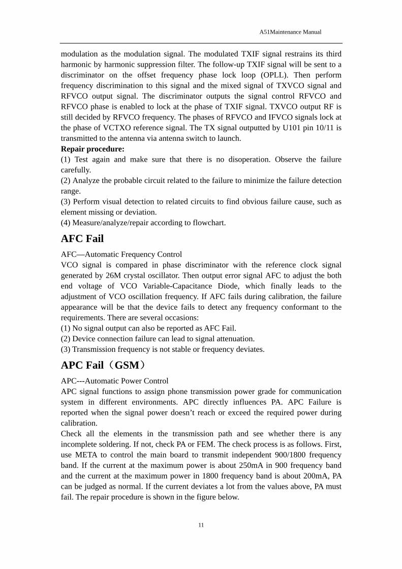
modulation as the modulation signal. The modulated TXIF signal restrains its third harmonic by harmonic suppression filter. The follow-up TXIF signal will be sent to a discriminator on the offset frequency phase lock loop (OPLL). Then perform frequency discrimination to this signal and the mixed signal of TXVCO signal and RFVCO output signal. The discriminator outputs the signal control RFVCO and RFVCO phase is enabled to lock at the phase of TXIF signal. TXVCO output RF is still decided by RFVCO frequency. The phases of RFVCO and IFVCO signals lock at the phase of VCTXO reference signal. The TX signal outputted by U101 pin 10/11 is transmitted to the antenna via antenna switch to launch. Repair procedure: (1) Test again and make sure that there is no disoperation. Observe the failure carefully. (2) Analyze the probable circuit related to the failure to minimize the failure detection range. (3) Perform visual detection to related circuits to find obvious failure cause, such as element missing or deviation. (4) Measure/analyze/repair according to flowchart.
AFC Fail AFC—Automatic Frequency Control VCO signal is compared in phase discriminator with the reference clock signal generated by 26M crystal oscillator. Then output error signal AFC to adjust the both end voltage of VCO Variable-Capacitance Diode, which finally leads to the adjustment of VCO oscillation frequency. If AFC fails during calibration, the failure appearance will be that the device fails to detect any frequency conformant to the requirements. There are several occasions: (1) No signal output can also be reported as AFC Fail. (2) Device connection failure can lead to signal attenuation. (3) Transmission frequency is not stable or frequency deviates.
APC Fail(GSM) APC---Automatic Power Control APC signal functions to assign phone transmission power grade for communication system in different environments. APC directly influences PA. APC Failure is reported when the signal power doesn’t reach or exceed the required power during calibration. Check all the elements in the transmission path and see whether there is any incomplete soldering. If not, check PA or FEM. The check process is as follows. First, use META to control the main board to transmit independent 900/1800 frequency band. If the current at the maximum power is about 250mA in 900 frequency band and the current at the maximum power in 1800 frequency band is about 200mA, PA can be judged as normal. If the current deviates a lot from the values above, PA must fail. The repair procedure is shown in the figure below.

A51Maintenance Manual
12
Base band MTK uses relatively high integration and has limited peripheral independent elements.
Check whether there is any additional element, missing or wrong element before hot
air gun is used. If visual detection fails to find problem, use some equipments to find
failure positions。 (1) Below 20MA: indicates that power starts working but the next action is not performed. The cause can be incomplete soldering or damage in power management, CPU or 26M circuit. (2) 20~25MA: the cause can be: there is no download software; software functions abnormally; or, CPU cannot read or execute software normally. (3) 30~90MA: if the software, 26M and 32K are all normal, the cause can be
incomplete soldering. Check U201 and U401 Startup process: When the Power-On button is pressed, PWRKEY will detect a low voltage. The internal PMIC will turn on the LDOs which provide power-supply to base band 30ms later; then the RESET circuit of the PMIC will generate the reset signal 200ms later to make the base band chip run the power-on software

A51Maintenance Manual
13

A51Maintenance Manual
14
Fail to download Make sure that the download current of main board is normal and important I/O interfaces including J501/CPU and U201/Flash U401 are normal.

A51Maintenance Manual
15
Bluetooth failure Please refer to the details of Bluetooth circuit description in Part 1. First perform visual examination to check whether there are missing pieces on related circuits or significant deviation. Then perform circuit analysis according to the maintenance process.

A51Maintenance Manual
16
3 Trouble shooting and flow chart
3.1 Unable to power on the handset
A51Maintenance Manual
17
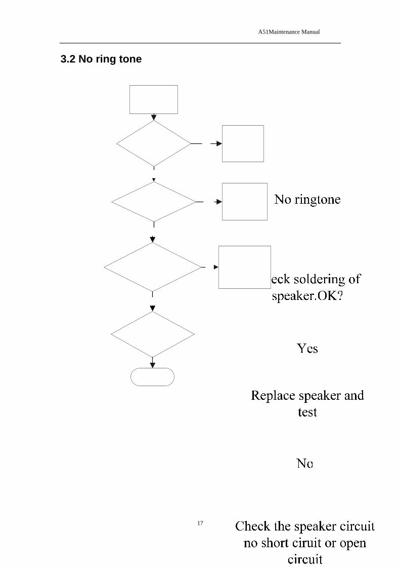
3.2 No ring tone

A51Maintenance Manual
18
3.3 LCD display fault

A51Maintenance Manual
19
3.4 Charging fault

A51Maintenance Manual
20
3.5 Camera fault
Check camera for damage
Failure to use camera
OK
Replace new cameraYes
Check if camera is soldered or assembled well
No
Yes Solder camera connector or Re-assemble camera
Check camera circuit for fault
No
Yes Mark the mainboard with analysis result
Replace new mainboard
No

A51Maintenance Manual
21
3.6 Fail to identify SIM card

A51Maintenance Manual
22
3.7 MIC fault

A51Maintenance Manual
23
3.8 Keypad fault
Check : DOME is pasted and keymat is assembled correctly
Keypad doesn’t work correctly
OK
Paste the DOME or assemble keymat againYes
Is there any dirty on keypad surface?
No
Yes Clean keypad surface and test
No
Replace new mainboard
No
Is sidekey soldered well?No short circuit Yes Solder or replace sidekey

A51Maintenance Manual
24
3.9 Receiver fault
Is receiver ok ?No broken wire
No voice in receiver
OK
Replace new receiverNo
Check receiver connector for soldering defect
Yes
Yes Solder receiver connector
No
Replace new mainboard
No
Check receiver circuit for any fault Yes Mark the mainboard with
analysis result

A51Maintenance Manual
25
3.10 Vibrate fault
Is vibrator soldered well ?
Vibrator fault or No vibration
OK
Solder vibrator or replace vibratorNo
Check : Wire of vibrator isn’t broken
No
Yes Replace vibrator
No
Replace new mainboard
Yes
Check vibrator circuitNo short circuit or open circuit No Mark the mainboard with
analysis result

A51Maintenance Manual
26
3.11 FM fault

A51Maintenance Manual
27
3.12 No signal
Is RF antenna assembled correctly?
No RF signal
OK
Re-assemble BT anntenaNo
Is the phone set into Flying mode?
Yes
Yes Return to Normal mode
No
Replace new mainboard
No
Check RF circuit for any fault Yes Mark the mainboard with analysis result
A51Maintenance Manual
28
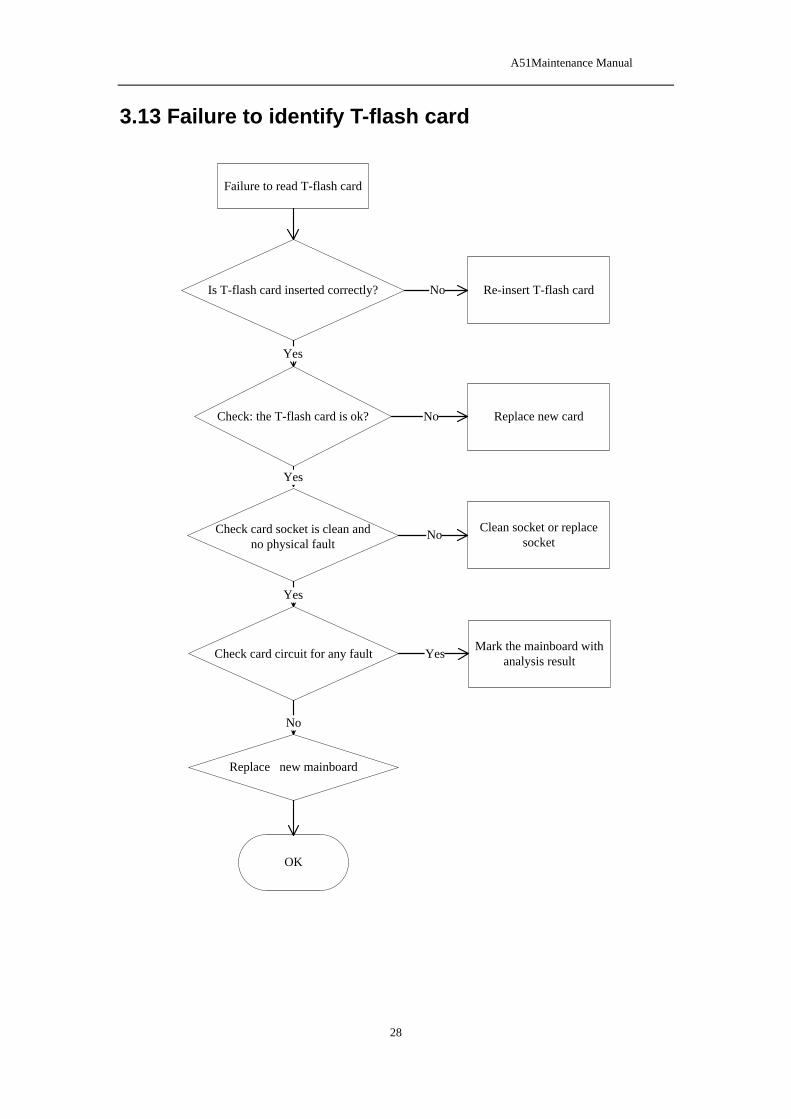
3.13 Failure to identify T-flash card
Is T-flash card inserted correctly?
Failure to read T-flash card
OK
Re-insert T-flash cardNo
Check: the T-flash card is ok?
Yes
No Replace new card
Yes
Replace new mainboard
No
Check card socket is clean and no physical fault
No Clean socket or replace socket
Check card circuit for any fault Yes Mark the mainboard with analysis result
Yes

A51Maintenance Manual
29
3.14 Earphone fault
Check: earphone is ok?No damage
Failure to use earphone
OK
Replace new earphoneNo
Check earphone connector for soldering defect
Yes
Yes Solder earphone connector
No
Replace new mainboard
No
Is there any foreign matter in earphone connector? Yes Clean or replace connector
Check earphone circuit for any fault Yes Mark the mainboard with
analysis result
No

A51Maintenance Manual
30
3.15 Unable to use USB
Check : USB cable is ok, no pin of connector is broken
Uable to use USB
OK
Replace new USB cableNo
Check if USB connector is solder ok, no short circuit
Yes
No Solder or replace USB connector
Replace new mainboard
Yes
END