panelwork 2009+
TRANSCRIPT

8/21/2019 Panelwork 2009+
http://slidepdf.com/reader/full/panelwork-2009 1/313
© Renault s.a.s 2008
"The repair methods given by the manufacturer in this document are based on the technical
specifications current when it was prepared.
The methods may be modified as a result of changes introduced by the manufacturer in theproduction of the various component units and accessories from which his vehicles areconstructed."
All copyrights reserved by Renault.
The reproduction or translation in part of whole of the present document, as well as the useof the spare parts reference numbering system, are prohibited without the prior writtenconsent of Renault.
JANUARY 2009 Edition Anglaise
X85
4 Panelwork
40A GENERAL INFORMATION
41A FRONT LOWER STRUCTURE
41B CENTRE LOWER STRUCTURE
41C SIDE LOWER STRUCTURE
41D REAR LOWER STRUCTURE
42A FRONT UPPER STRUCTURE
43A SIDE UPPER STRUCTURE
44A REAR UPPER STRUCTURE
45A TOP OF BODY
47A SIDE OPENING ELEMENTS
48A NON-SIDE OPENING ELEMENTS
8/21/2019 Panelwork 2009+
http://slidepdf.com/reader/full/panelwork-2009 2/313
CLIO III - Section 4
Contents
Page
CLIO III - Section 4ContentsPage
40A GENERAL INFORMATION
Bodywork special tooling:Use 40A-1
Structural bodyworkreference material: Use 40A-5
Vehicle on repair bench:Description 40A-7
Sub-frame: Specifications 40A-11
Hollow body parts inserts:List and location of
components 40A-16
Earths on the body: List andlocation of components 40A-23
Vehicle removable sectionstructure: Description 40A-28
Vehicle front sectionstructure: Description 40A-30
Vehicle side sectionstructure: Description 40A-32
Vehicle central sectionstructure: Description 40A-37
Vehicle structure rearsection: Description 40A-39
Structure components to bepositioned on body repairbench: Description 40A-46
Hollow body parts inserts:Precautions for repair 40A-51
41A FRONT LOWER STRUCTURE
Lower front end crossmember: General description 41A-1
Front impact cross member:Removal - Refitting 41A-2
Radiator support crossmember: General description 41A-3
Radiator support crossmember: Removal - Refitting 41A-4
Front side member: General
description 41A-5
Front side member:Description 41A-8
Front side member, centralsection: General description 41A-11
Front side member, centralsection: Description 41A-12
Front section of front sidemember closure panel:General description 41A-13
Front section of front sidemember closure panel:Description 41A-15
Battery tray support: Generaldescription 41A-17
Radiator cross membermounting: Generaldescription 41A-18
Radiator cross member
support: Description 41A-19

8/21/2019 Panelwork 2009+
http://slidepdf.com/reader/full/panelwork-2009 3/313
Contents
Front mounting of front sub-frame: General description 41A-20
Engine mounting: Generaldescription 41A-21
Engine mounting:Description 41A-22
Front half unit: Description 41A-24
Sub-frame rear mounting:General description 41A-28
Front towing ring: Generaldescription 41A-29
Engine tie-rod attachment:Description 41A-30
41B CENTRE LOWER STRUCTURE
Centre floor front lateralcross member: Generaldescription 41B-1
Centre floor front lateralcross member : Description 41B-3
Front cross member underfront seat: Generaldescription 41B-5
Front cross member underfront seat: Description 41B-6
Rear cross member underfront seat: Generaldescription 41B-7
Rear cross member underfront seat: Description 41B-8
Centre floor, side section:General description 41B-9
Central floor, side section:Description 41B-11
41A FRONT LOWER STRUCTURE 41C SIDE LOWER STRUCTURE
Sill panel: Description 41C-1
Sill panel closure panel:Description 41C-11
Sill panel reinforcement:General description 41C-16
Sill panel reinforcement:Description 41C-17
41D REAR LOWER STRUCTURE
Luggage retainer crosspiece: Removal - Refitting 41D-1
Rear floor, front section:General description 41D-2
Rear floor, front section:Description 41D-4
Rear floor rear section:General description 41D-6
Rear floor rear section:
Description 41D-7
Rear side member assembly:Description 41D-10
Rear side member: Generaldescription 41D-13
Rear side member, rearsection: Description 41D-16
Rear floor front crossmember stiffener: Generaldescription 41D-17
Rear floor front crossmember stiffener:Description 41D-19
Rear floor centre crossmember: General description 41D-20
Rear floor centre crossmember: Description 41D-21
Rear floor rear crossmember: Description 41D-23
Rear impact lower crossmember: Removal - Refitting 41D-24

8/21/2019 Panelwork 2009+
http://slidepdf.com/reader/full/panelwork-2009 4/313
Contents
Rear towing ring: Generaldescription 41D-25
Rear floor extension:Description 41D-26
Rear side memberextension: Description 41D-28
42A FRONT UPPER STRUCTURE
Front wing: General
description 42A-1
Front wing: Removal -Refitting 42A-3
Front wing: Adjusting 42A-6
Front wing lower mountingsuppor t: General description 42A-9
Front wing lower mountingsupport: Removal - Refitting 42A-10
Front wing upper mounting
support: General description 42A-11
Front wing upper mountingsupport: Removal - Refitting 42A-12
Front: General description 42A-15
Front: Removal - Refitting 42A-16
Scuttle side panel: Generaldescription 42A-18
Cowl side panel: Description 42A-20
Scuttle side panel upperreinforcement: Generaldescription 42A-22
Scuttle side panel upperreinforcement: Description 42A-23
Front wheel arch: Generaldescription 42A-25
Front wheel arch: Description 42A-26
Dashboard cross member:Removal - Refitting 42A-29
41D REAR LOWER STRUCTURE
Windscreen aperture lowercross member closure panel:
General description 42A-34
Windscreen aperture lowercross member closure panel:Description 42A-35
Bulkhead lower crossmember: General description 42A-37
Bulkhead side reinforcement:General description 42A-38
43A SIDE UPPER STRUCTURE
A-pillar: General description 43A-1
A-pillar: Description 43A-2
A-pillar reinforcement:General description 43A-5
A-pillar reinforcement:Description 43A-6
Windscreen pillar lining:General description 43A-7
Windscreen pillar lining:Description 43A-8
B-pillar: General description 43A-12
B-pillar reinforcement:General description 43A-15
B-pillar reinforcement:Description 43A-17
B-pillar lining: Generaldescription 43A-21
Body side: Generaldescription 43A-22
Body side: Description 43A-24
Body side front section:General description 43A-27
Body side front section:Description 43A-28
Upper body panel: Generaldescription 43A-33
42A FRONT UPPER STRUCTURE

8/21/2019 Panelwork 2009+
http://slidepdf.com/reader/full/panelwork-2009 5/313
Contents
Upper body panel:Description 43A-35
Roof drip moulding lining:General description 43A-39
Roof drip moulding lining:Description 43A-40
Front jack support: Generaldescription 43A-41
44A REAR UPPER STRUCTURE
Rear wing panel: Generaldescription 44A-1
Rear wing panel: Description 44A-3
Rear wing panel rainchannel: General description 44A-11
Rear wing panel rainchannel: Description 44A-12
Balancing ball joint: General
description 44A-13
Rear lights support: Generaldescription 44A-14
Rear lights support:Description 44A-15
Lights support lining:Description 44A-18
Outer rear wheel arch:General description 44A-22
Outer rear wheel arch:Description 44A-24
Body side rear lining:Description 44A-30
Rear end panel: Generaldescription 44A-40
Rear end panel: Description 44A-41
Rear end panel lining:General description 44A-43
Rear end panel lining:Description 44A-44
43A SIDE UPPER STRUCTURE 45A TOP OF BODY
Roof: General description 45A-1
Roof: Description 45A-2
Roof front cross member:General description 45A-10
Roof centre cross member:General description 45A-11
Roof centre cross member:Description 45A-12
Roof rear cross member:General description 45A-14
Roof rear cross member:Description 45A-15
47A SIDE OPENING ELEMENTS
Front side door: Removal -Refitting 47A-1
Front side door: Adjustment 47A-3
Front side door: Stripping -Restoring 47A-7
Rear side door: Removal -Refitting 47A-8
Rear side door: Adjustment 47A-10
Rear side door: Stripping -Restoring 47A-13
Fuel filler flap cover:Removal - Refitting 47A-14
48A NON-SIDE OPENING ELEMENTS
Bonnet: Removal - Refitting 48A-1
Bonnet: Adjustment 48A-3
Tailgate: Removal - Refitting 48A-6
Tailgate: Adjusting 48A-8
Tailgate: Stripping-
Rebuilding 48A-11

8/21/2019 Panelwork 2009+
http://slidepdf.com/reader/full/panelwork-2009 6/31340A-1
GENERAL INFORMATION
Bodywork special tooling: Use 40AUSING THE DASHBOARD CROSS MEMBERREMOVAL TOOL Car. 1765
a Use this tool as indicated in the dashboard removalprocedure.
a
Fit the tool Car. 1765 as far as the stop (10) .Screw the rod (11) onto the body (10) as far as thestop.
Firmly lock tool body in the same way as a lock nutagainst the dashboard cross member nut while hol-ding hexagon bolt.
a Unscrew the whole tool as far as the stop and tigh-ten it gently (during this operation, the beam nut,which has a left-hand thread, screws into the beamand disengages it from the A-pillar).
a Hold the tool body (10) and unlock the rod (11) .
Unscrew dashboard cross member rod to removethe tool.
101308
112407
112410
112408
WARNINGTo maintain the adjustment of the dashboardcross member and therefore make refittingeasier, only loosen the lock nut on one side.

8/21/2019 Panelwork 2009+
http://slidepdf.com/reader/full/panelwork-2009 7/31340A-2
GENERAL INFORMATION
Bodywork special tooling: Use 40AUSING THE DASHBORAD PROTECTION TOOL Car.1764
a Use this tool when replacing the windscreen:
- remove the A-pillar trims,
- position the dashboard protector to prevent dama-ge.
18263

8/21/2019 Panelwork 2009+
http://slidepdf.com/reader/full/panelwork-2009 8/31340A-3
GENERAL INFORMATION
Bodywork special tooling: Use 40APREPARING THE TOOL Car. 1504
111554

8/21/2019 Panelwork 2009+
http://slidepdf.com/reader/full/panelwork-2009 9/31340A-4
GENERAL INFORMATION
Bodywork special tooling: Use 40Aa (1) Mandrel mounting
- (2) Mandrels
- (3) Tightening bolt
- (4) Body
- (5) Anvils
- (6) Special nut
- (7) Nuts
- (8) Studs
- (9) Thrust nut
- Select the mandrel, anvil and insert assemblyadapted to the crimping operation to be carried out.
- Into the mandrel mounting (1) , screw the mandrel(2) (left-hand thread).
- Tighten the bolt (3) onto the body (4) until the stop(left-hand thread).
- Into the body (4) , screw the anvil (5) (left-handthread).
- Fit the assembly (1) and (2) into the body of the to-ol.
- Screw the insert (left-hand thread) onto the pullrod.
USING TOOL CAR. 1504
a Turn the bolt using a 24 spanner, holding the tool
handle manually.
To fi t the special nut (6) , position the mandrelacross the crimped nut and tighten it onto thethrust nut (9) .
WARNING
Each time a panel is stripped in the workshop(e.g. when drilling), degrease and wipe the areaand then use a fine paintbrush to apply the fol-lowing:
- a pre-treatment primer,
- a two-part primer,
- paint in the vehicle body colour.
16069
WARNING
The operator should be able to feel when thecrimping is complete (more force required fortightening). The insert has been crimped cor-rectly when there is no more rotational play, carryout this check before unscrewing the "pull rod -mandrel" assembly.

8/21/2019 Panelwork 2009+
http://slidepdf.com/reader/full/panelwork-2009 10/31340A-5
GENERAL INFORMATION
Structural bodywork reference material: Use
B85 or C85
40A
I - - CLASSIFYING INFORMATION
This information is classified in two complementary do-cuments:
1 - Vehicle structure bodywork repair procedures(MR of the vehicle concerned)
This document comprises two sections:
a - Section 0:
This section does not contain repair methods, it onlycontains description information; It consists of severalsubsections:
- 01C Vehicle bodywork specifications,
- 02A Lifting equipment,- 02B Bodywork innovations,
- 03B Collision,
- 04E Painting,
- 05B Bodywork equipment and tooling.
b - Section 4:
This section consists of several subsections:
- 40A General information,
- 41A Lower front structure,
- 41B Lower central structure,
- 41C Lower side structure,
- 41D Lower rear structure,
- 42A Upper front structure,
- 43A Upper side structure,
- 44A Upper rear structure,
- 45A Top of body,
- 47A Side opening elements,
- 48A Non-side opening elements.
These subsections are linked to the ReplacementParts Catalogue and contain two types of information:
- Section 1: General description. This section con-tains information relating to generic structural spareparts and to their design. This information may be thesame for several vehicles.
- Section 2: Description, Removal - Refitting, Strip -Rebuild and Adjustment. This section contains in-formation relating to structural spare parts and thespecial features of the vehicle concerned.
2 - Fundamentals of the structure bodywork repair(MR 400)
This document comprises two sections:
a - Section 0:
This section does not contain any repair procedures; itonly contains descriptive information and has only onesubsection:
- 03B Collision
b - Section 4:
This section contains information about using the equi-pment and products, and basic operating ranges whichconcern the bodyshop technician. This section onlyhas one subsection.
- 40A Structure general information
II - INFORMATION SEARCH
Note:
Always read both parts in order to have all the
necessary information to repair the vehicle.
Questions Answers
Features of specific tools to repair a given vehicle. Refer firstly to section 0 of the Vehicle MR then referto the « special tooling catalogue » or the « garageequipment catalogue » .
Features of specific products to repair a given vehicle. Firstly refer to section 0 of the Vehicle MR then referto the « IXELL product catalogue » .
Use of a specific tool to repair a given vehicle. firstly refer to subsection 0 of the Vehicle MR.
Using a bodywork tool. Firstly refer to subsection 40 of the Vehicle MR thenMR 400.
8/21/2019 Panelwork 2009+
http://slidepdf.com/reader/full/panelwork-2009 11/31340A-6
GENERAL INFORMATION
Structural bodywork reference material: Use
B85 or C85
40A
Information concerning the replacement parts of agiven vehicle regarding:
- the possibilities of replacement with the position onvehicle,
- an adaptation before the assembly,
- a cutting place with the special notes on this cut,
- special notes on right-left symmetry.
- special features of the version or equipment.
Refer to the subsection which corresponds to the partconcerned: 41 to 48 of the Vehicle MR, section 2
Information concerning the spare parts of a givenvehicle, the composition and the specifications ofeach part it contains.
Firstly refer to the parts description exploded view insubsection 40 of the Vehicle MR.
If this is detailed in the document, refer to subsections41 to 48 of the Vehicle MR part 2 which correspondswith the part concerned.
If this does not appear in the description, refer to sub-section 41 to 48 for the part in the next level up.
Information concerning:
- details of panel overlap on a joint,
- a procedure and an operational mode relating to anew type of assembly in Renault,
- a method for using a tool or a new product which isunfamiliar in Renault.
Refer to the subsection which corresponds to the partconcerned: 41 to 48 of the Vehicle MR then subsec-tion 40 of Vehicle MR 400.
Towing and raising a vehicle after an accident. Firstly refer to subsection 40 of the Vehicle MR thenthe equipment catalogue.
Conveyance and handling of a vehicle after an acci-dent.
Firstly refer to subsection 40 of the MR 400 then theequipment catalogue.
Combination of impacts to repair a given vehicle. Refer to section 0 of the Vehicle MR
Logic of the impact combination. Refer to section 0 of the Vehicle MR
Fault finding on an impact for a given vehicle. Firstly refer to section 0 of the Vehicle MR then sec-tion 0 of Repair Manual 400.
Logic of impact fault finding. See section 0 of MR 400.
General instructions for:
- repair,
- safety,
- preparing a vehicle,
- tool classification,
- precautions for repair.
See section 0 of MR 400.
Questions Answers

8/21/2019 Panelwork 2009+
http://slidepdf.com/reader/full/panelwork-2009 12/31340A-7
GENERAL INFORMATION
Vehicle on repair bench: Description 40AI - MAIN REFERENCE POINTS BEFORE TRIM-SETTING
1 - Front sub-frame in place
The jig crowns the front sub-frame rear mounting bolt(A) .
Use this situation for a rear impact or a light frontal im-pact without removal of the mechanical components.
2 - Front mechanical components removed
The jig rests under the sub-frame mounting unit and iscentred in the threaded hole (B) .
Use this situation for a frontal impact with removal ofthe mechanical components.
II - SECONDARY FRONT TRIM-SETTINGREFERENCE POINT
The body jig covers radiator mounting cross membermounting bolt (C) .
Use this situation to confirm the trim-setting following arear impact, (e.g.: to replace a rear side member as-sembly).
It is used to confirm the vehicle level in case of doubtabout the deformation of a main rear reference point.
112027
112250
Note:
If it is suspected that one of these points may bedeformed, use two additional points located in anarea not affected by the impact in order to confirmtrim-setting.
112028

8/21/2019 Panelwork 2009+
http://slidepdf.com/reader/full/panelwork-2009 13/31340A-8
GENERAL INFORMATION
Vehicle on repair bench: Description 40AIII - MAIN REAR TRIM-SETTING REFERENCEPOINT
1 - Rear mechanical components in place
The jig supports the underside of the rear axle fork andis centred in rear axle mounting bolt tapped hole (D) .
Use this situation for a frontal impact or a light rear im-pact.
2 - Rear mechanical components removed
The jig rests under the rear side member and is cen-tred in the tapped hole (E) .
Use this situation for a rear impact with removal of themechanical components.
IV - SECONDARY REAR TRIM-SETTINGREFERENCE POINT
The jig rests under the rear side member and is positio-ned in square hole (F) .
Use this situation to confirm the trim-setting following afrontal impact (e.g.: to replace a complete front halfunit).
It is used to confirm the vehicle trim setting in case ofdoubt about the deformation of a main front referencepoint.
112022
112249
Note:
If it is suspected that one of these points may bedeformed, use two additional points located in anarea not affected by the impact in order to confirmtrim-setting.
112098

8/21/2019 Panelwork 2009+
http://slidepdf.com/reader/full/panelwork-2009 14/31340A-9
GENERAL INFORMATION
Vehicle on repair bench: Description 40AV - FITTING THE VEHICLE ANCHORING KIT
1 - At the front
Remove
- the wheels,
- the blanking covers (1) and (2) .
Fit inserts (3) .
Fit the mountings (4) without tightening them.
Position the (5) and secure it with the bolts (6) .
Finish the tightening operation with the mountings (7) .
109379
109380
109378
109377

8/21/2019 Panelwork 2009+
http://slidepdf.com/reader/full/panelwork-2009 15/31340A-10
GENERAL INFORMATION
Vehicle on repair bench: Description 40A2 - At the rear
Position the clamp (8) on the horizontal flange on therear section of the sill panel and lock it with the bolt (9) .
Position the vehicle on the body jig bench clamps.
109376
WARNING
The sub-frame on this vehicle is protected by pro-ducts which guarantee the 12-year anti-corrosionwarranty.
After the operation, protect the hollow sections ofthe front side cross members and refit the blankingcovers. Replace any damaged blanking covers.
Re-apply the anti-gravel protection if it has deterio-rated.

8/21/2019 Panelwork 2009+
http://slidepdf.com/reader/full/panelwork-2009 16/31340A-11
GENERAL INFORMATION
Sub-frame: Specifications 40A
K85
No. Description X Dimen-sion Y Dimen-sion Z Diameter Angle (indegrees)
Front sub-frame rear mountingwith mechanical components
301 305 6.5 M12
Rear axle guide 1921 -582 118 20 x 20
Rear axle assembly front moun-ting, without mechanical compo-nents
2077.3 -633 118 24 x 24
Rear axle assembly front moun-
ting, with mechanical compo-nents
2077.3 -633 113 M10
Rear axle assembly front moun-ting, without mechanical compo-nents
2047.4 -541.3 118 24 x 24
Rear axle assembly front moun-ting, with mechanical compo-nents
2047.4 -541.3 113 M10
Rear axle assembly front moun-ting, without mechanical compo-
nents
2166 -536 118 24 x 24
Rear axle assembly front moun-ting, with mechanical compo-nents
2166 -536 113 M10
Front subframe front mounting -141.5 -478 260.5 M12
Front subframe front mounting -141.5 468 256 M12
Rear shock absorber uppermounting
2614.2 -561.9 534.4 ∅ 20
Front shock absorber upper stop 6.81 -583.6 669.4 ∅
98 X 7˚ ; Y 1˚Front shock absorber uppermounting
-55.5 -618.4 673.8 M8 X 7˚ ; Y 1˚
Front shock absorber uppermounting
-23.3 -518.7 669.2 M8 X 7˚ ; Y 1˚
Front shock absorber upper
mounting
68.1 -624 660 M8 X 7˚ ; Y 1˚
Front side member rear moun-ting
547 -410 9.8 ∅ 16
Front side member front leaderpin
-283.5 -460.8 292.8 16 x 16

8/21/2019 Panelwork 2009+
http://slidepdf.com/reader/full/panelwork-2009 17/31340A-12
GENERAL INFORMATION
Sub-frame: Specifications 40A
Front side member front leaderpin
-305.5 471.3 292.8 16 x 16
Front side member front moun-ting without mechanical compo-nents
-502 -476 83.5 M12
Front side member front moun-ting with mechanical compo-nents
-502 -476 77.5 M12
Front side member front moun-ting without mechanical compo-nents
-525 492 83.5 M12
Front side member front moun-ting with mechanical compo-
nents
-525 492 77.5 M12
Rear side member front leaderpin
1957.5 -614 118 20 x 20
Rear side member rear leaderpin
2533 -497.9 176.8 20 x 20
Rear side member rear leaderpin
2533 487.5 176.8 20 x 20
Rear side member rear moun-ting
2942 -529.4 220 ∅ 12.2 90˚
Rear side member rear moun-ting
2942 519.4 220 ∅ 12.2 90˚
Front end cross member leaderpin
-498.2 -530.9 265 ∅ 16 90˚
Front end cross member leaderpin
-496.4 534.9 265 ∅ 16 90˚
Front end cross member moun-ting
-503.6 -453 415 M10 90˚
Front end cross member moun-ting
-503.3 464.6 415 M10 90˚
Engine mounting -317 489 449 M10 180˚
Engine mounting -147 511 449 M10 180˚
Additional engine mounting (tie-rod)
-86.2 481.1 604.5 M12 180˚

8/21/2019 Panelwork 2009+
http://slidepdf.com/reader/full/panelwork-2009 18/31340A-13
GENERAL INFORMATION
Sub-frame: Specifications 40A
B85 or C85 or S85
No. Description X Dimen-sion Y Dimen-sion Z Diameter Angle (indegrees)
Front sub-frame rear mountingwith mechanical components
301 305 6.5 M12
Rear axle guide 1921 -582 118 20 x 20
Rear axle assembly front moun-ting, without mechanical compo-nents
2077.3 -633 118 24 x 24
Rear axle assembly front moun-
ting, with mechanical compo-nents
2077.3 -633 113 M10
Rear axle assembly front moun-ting, without mechanical compo-nents
2047.4 -541.3 118 24 x 24
Rear axle assembly front moun-ting, with mechanical compo-nents
2047.4 -541.3 113 M10
Rear axle assembly front moun-ting, without mechanical compo-
nents
2166 -536 118 24 x 24
Rear axle assembly front moun-ting, with mechanical compo-nents
2166 -536 113 M10
Front subframe front mounting -141.5 -478 260.5 M12
Front subframe front mounting -141.5 468 256 M12
Rear shock absorber uppermounting
2614.2 -561.9 534.4 ∅ 20
Front shock absorber upper stop 6.81 -583.6 669.4 ∅
98 X 7˚ ; Y 1˚Front shock absorber uppermounting
-55.5 -618.4 673.8 M8 X 7˚ ; Y 1˚
Front shock absorber uppermounting
-23.3 -518.7 669.2 M8 X 7˚ ; Y 1˚
Front shock absorber upper
mounting
68.1 -624 660 M8 X 7˚ ; Y 1˚
Front side member rear moun-ting
547 -410 9.8 ∅ 16
Front side member front leaderpin
-283.5 -460.8 292.8 16 x 16

8/21/2019 Panelwork 2009+
http://slidepdf.com/reader/full/panelwork-2009 19/31340A-14
GENERAL INFORMATION
Sub-frame: Specifications 40A
Front side member front leaderpin
-305.5 471.3 292.8 16 x 16
Front side member front moun-ting without mechanical compo-nents
-502 -476 83.5 M12
Front side member front moun-ting with mechanical compo-nents
-502 -476 77.5 M12
Front side member front moun-ting without mechanical compo-nents
-525 492 83.5 M12
Front side member front moun-ting with mechanical compo-
nents
-525 492 77.5 M12
Rear side member front leaderpin
1957.5 -614 118 20 x 20
Rear side member rear leaderpin
2533 -497.9 176.8 20 x 20
Rear side member rear leaderpin
2533 487.5 176.8 20 x 20
Rear side member rear moun-ting
2876 -529.4 220 ∅ 12.2 90˚
Rear side member rear moun-ting
2876 519.4 220 ∅ 12.2 90˚
Front end cross member leaderpin
-498.2 -530.9 265 ∅ 16 90˚
Front end cross member leaderpin
-496.4 534.9 265 ∅ 16 90˚
Front end cross member moun-ting
-503.6 -453 415 M10 90˚
Front end cross member moun-ting
-503.3 464.6 415 M10 90˚
Engine mounting -317 489 449 M10 180˚
Engine mounting -147 511 449 M10 180˚
Additional engine mounting (tie-rod)
-86.2 481.1 604.5 M12 180˚

8/21/2019 Panelwork 2009+
http://slidepdf.com/reader/full/panelwork-2009 20/31340A-15
GENERAL INFORMATION
Sub-frame: Specifications 40A
112264

8/21/2019 Panelwork 2009+
http://slidepdf.com/reader/full/panelwork-2009 21/31340A-16
GENERAL INFORMATION
Hollow body parts inserts: List and location of components 40A
B85
112467

8/21/2019 Panelwork 2009+
http://slidepdf.com/reader/full/panelwork-2009 22/31340A-17
GENERAL INFORMATION
Hollow body parts inserts: List and location of components 40A
C85 or S85
112466

8/21/2019 Panelwork 2009+
http://slidepdf.com/reader/full/panelwork-2009 23/31340A-18
GENERAL INFORMATION
Hollow body parts inserts: List and location of components 40A
Front wing upper mounting bracket insert (1) .
Exterior A-pillar insert (2) .
K85
126694
112486
112484
8/21/2019 Panelwork 2009+
http://slidepdf.com/reader/full/panelwork-2009 24/31340A-19
GENERAL INFORMATION
Hollow body parts inserts: List and location of components 40A
Interior A-pillar insert (3) .
A-pillar insert (4) .
B-pillar insert (5) .
Wheel arch insert (6) .
112485
112481
B85 or K85
112475
112470

8/21/2019 Panelwork 2009+
http://slidepdf.com/reader/full/panelwork-2009 25/31340A-20
GENERAL INFORMATION
Hollow body parts inserts: List and location of components 40A
Interior quarter panel insert (7) .
Rear quarter panel insert (8) .
Exterior quarter panel insert (9) .
Right-hand quarter panel insert (10) .
B85
112473
112472
112471
112474

8/21/2019 Panelwork 2009+
http://slidepdf.com/reader/full/panelwork-2009 26/31340A-21
GENERAL INFORMATION
Hollow body parts inserts: List and location of components 40A
B-pillar insert (11) .
Exterior quarter panel insert (12) .
Quarter panel insert (13) .
Rear quarter panel insert (14) .
C85 or S85
112480
112476
112479
K85
126695
8/21/2019 Panelwork 2009+
http://slidepdf.com/reader/full/panelwork-2009 27/31340A-22
GENERAL INFORMATION
Hollow body parts inserts: List and location of components 40A
Front quarter panel insert (15) .
Interior quarter panel insert (16) .
126696
126697

8/21/2019 Panelwork 2009+
http://slidepdf.com/reader/full/panelwork-2009 28/31340A-23
GENERAL INFORMATION
Earths on the body: List and location of components 40AFor the earth stud replacement procedure, see MR400.
WARNING
To avoid damaging the vehicle's electrical and elec-tronic components, disconnect the earths of any
wiring near the weld area.
Position the welding machine earth as close aspossible to the weld zone (see MR 400).
B85
112467

8/21/2019 Panelwork 2009+
http://slidepdf.com/reader/full/panelwork-2009 29/31340A-24
GENERAL INFORMATION
Earths on the body: List and location of components 40A
C85 or S85
112466

8/21/2019 Panelwork 2009+
http://slidepdf.com/reader/full/panelwork-2009 30/31340A-25
GENERAL INFORMATION
Earths on the body: List and location of components 40A
DETAILED VIEW OF THE POSITION OF EARTHSON THE VEHICLE
K85
126694
112488
8/21/2019 Panelwork 2009+
http://slidepdf.com/reader/full/panelwork-2009 31/31340A-26
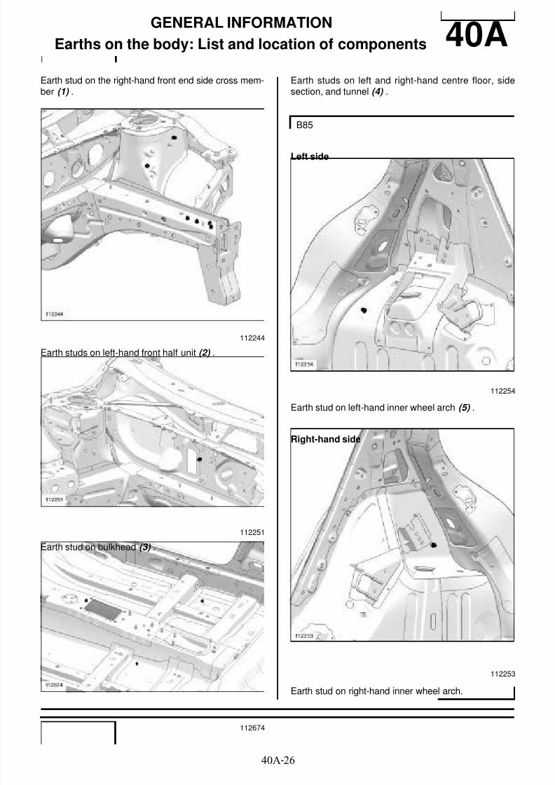
GENERAL INFORMATION
Earths on the body: List and location of components 40AEarth stud on the right-hand front end side cross mem-ber (1) .
Earth studs on left-hand front half unit (2) .
Earth stud on bulkhead (3) .
Earth studs on left and right-hand centre floor, sidesection, and tunnel (4) .
Left side
Earth stud on left-hand inner wheel arch (5)
.
Right-hand side
Earth stud on right-hand inner wheel arch.
112244
112251
112674
B85
112254
112253

8/21/2019 Panelwork 2009+
http://slidepdf.com/reader/full/panelwork-2009 32/31340A-27
GENERAL INFORMATION
Earths on the body: List and location of components 40A
Left side
Earth stud on left-hand inner wheel arch (7) .
Right-hand side
Earth stud on right-hand inner wheel arch (8) .
Earth stud on left-hand rear wheel arch (9) .
C85 or S85
112255
112252
K85
126698
8/21/2019 Panelwork 2009+
http://slidepdf.com/reader/full/panelwork-2009 33/31340A-28
GENERAL INFORMATION
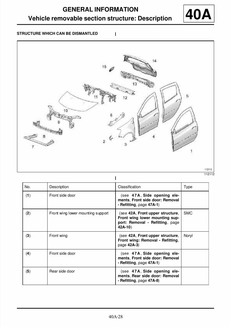
Vehicle removable section structure: Description 40ASTRUCTURE WHICH CAN BE DISMANTLED
112112
No. Description Classification Type
(1) Front side door (see 47A , Side opening ele-ments, Front side door: Removal- Refitting, page 47A-1)
(2) Front wing lower mounting support (see 42A, Front upper structure,Front wing lower mounting sup-port: Removal - Refitting, page
42A-10)
SMC
(3) Front wing (see 42A, Front upper structure,Front wing: Removal - Refitting,page 42A-3)
Noryl
(4) Front side door (see 47A , Side opening ele-ments, Front side door: Removal- Refitting, page 47A-1)
(5) Rear side door (see 47A , Side opening ele-ments, Rear side door: Removal- Refitting, page 47A-8)

8/21/2019 Panelwork 2009+
http://slidepdf.com/reader/full/panelwork-2009 34/31340A-29
GENERAL INFORMATION
Vehicle removable section structure: Description 40A
(6) Front wing upper mounting support (see 42A, Front upper structure,Front wing upper mounting sup-port: Removal - Refitting, page42A-12)
(7) Radiator suppor t cross member (see 41A, Front lower structure,Radiator support cross member:Removal - Refitting, page 41A-4)
(8) Frontal impact cross member (see 41A, Front lower structure,Front impact cross member:Removal - Refitting, page 41A-2)
Aluminium
(9) Front end panel (see 42A, Front upper structure,Front: Removal - Refitting, page42A-16)
Polypropy-lene
(10) Bonnet (see 48A, Non-side opening ele-ments, Bonnet: Removal - Refit-ting, page 48A-1)
Aluminium
(11) Dashboard cross member (see 42A, Front upper structure,Dashboard cross mem ber :Removal - Refitting, page 42A-29)
(12) Luggage retainer cross piece (see L u ggage retainer crosspiece: Description)
(13) Rear impact lower cross member (see 41D , Rear lower structure,Rear impact lower cross mem-
ber: Removal - Refitting, page41D-24)
Polypropy-lene
(14) Tailgate (see 48A, Non-side opening ele-ments, Tailgate: Removal - Refit-ting, page 48A-6)
(15) Fuel filler flap cover (see 47A , Side opening ele-ments, Fuel filler flap cover:Removal - Refitting, page 47A-14)
Noryl
8/21/2019 Panelwork 2009+
http://slidepdf.com/reader/full/panelwork-2009 35/31340A-30
GENERAL INFORMATION
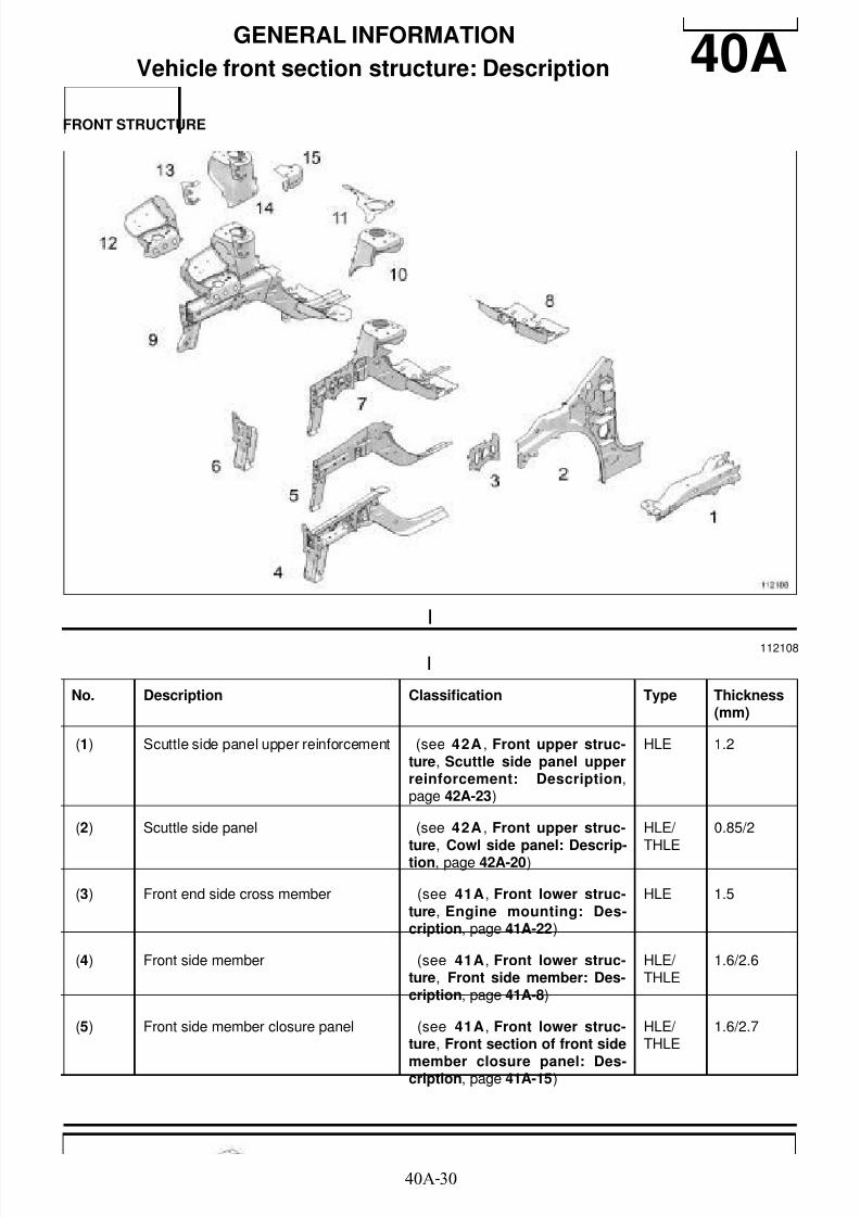
Vehicle front section structure: Description 40AFRONT STRUCTURE
112108
No. Description Classification Type Thickness(mm)
(1) Scuttle side panel upper reinforcement (see 42A , Front upper struc-ture, Scuttle side panel upperreinforcement: Description,page 42A-23)
HLE 1.2
(2) Scuttle side panel (see 42A , Front upper struc-
ture, Cowl side panel: Descrip-tion, page 42A-20)
HLE/
THLE
0.85/2
(3) Front end side cross member (see 41A, Front lower struc-ture, Engine mounting: Des-cription, page 41A-22)
HLE 1.5
(4) Front side member (see 41A, Front lower struc-ture, Front side member: Des-cription, page 41A-8)
HLE/ THLE
1.6/2.6
(5) Front side member closure panel (see 41A, Front lower struc-ture, Front section of front side
member closure panel: Des-cription, page 41A-15)
HLE/ THLE
1.6/2.7

8/21/2019 Panelwork 2009+
http://slidepdf.com/reader/full/panelwork-2009 36/31340A-31
GENERAL INFORMATION
Vehicle front section structure: Description 40A
(6) Radiator cross member mounting (see 41A, Front lower struc-ture, Radiator cross membersupport: Description, page 41A-19)
HLE 1.2/2.5
(7) Front left-hand half unit (see 41A, Front lower struc-ture, Front half unit: Descrip-tion, page 41A-24)
(8) Centre floor front side cross member (see 41B, Centre lower struc-ture, Centre floor front lateralcross member: Description,page 41B-3)
HLE 1
(9) Front right-hand half unit (see 41A, Front lower struc-ture, Front half unit: Descrip-tion, page 41A-24)
(10) Front left-hand wheel arch (see 42A , Front upper struc-ture, Front wheel arch: Descrip-tion, page 42A-26)
HLE 1.2/2
(11) Heater bulkhead reinforcement (see 41A, Front lower struc-ture, Front side member: Des-cription, page 41A-8) ;
1.5
(12) Engine stand (see 41A, Front lower struc-
ture, Engine mounting: Des-cription, page 41A-22)
HLE 1.5/2
(13) Windscreen wiper mounting (see 42A , Front upper struc-ture, Front wheel arch: Descrip-tion, page 42A-26)
1.5
(14) Front right-hand wheel arch (see 42A , Front upper struc-ture, Front wheel arch: Descrip-tion, page 42A-26)
HLE 1.2/2
(15) Engine tie-rod attachment (see 41A, Front lower struc-ture, Engine tie-rod attachment:
Description, page 41A-30)
HLE 2
No. Description Classification Type Thickness(mm)
8/21/2019 Panelwork 2009+
http://slidepdf.com/reader/full/panelwork-2009 37/31340A-32
GENERAL INFORMATION
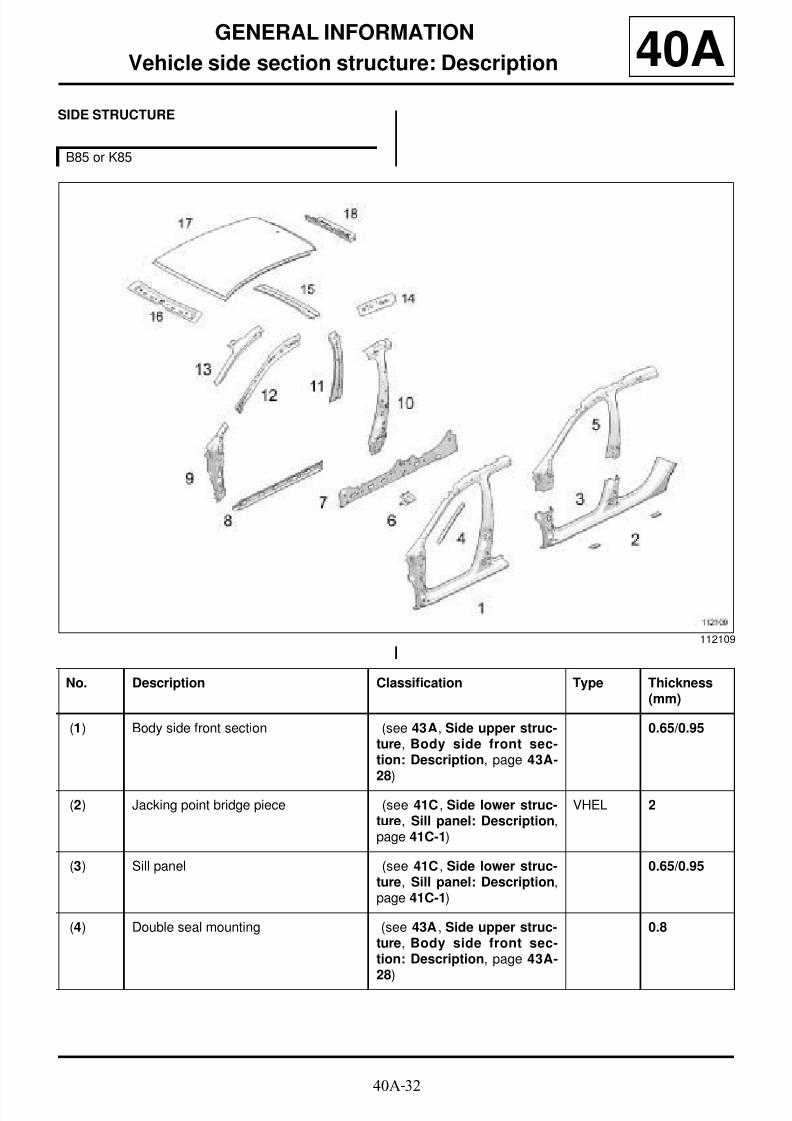
Vehicle side section structure: Description 40ASIDE STRUCTURE
B85 or K85
112109
No. Description Classification Type Thickness(mm)
(1) Body side front section (see 43A, Side upper struc-ture, Body side front sec-tion: Description, page 43A-28)
0.65/0.95
(2) Jacking point bridge piece (see 41C , Side lower struc-ture, Sill panel: Description,page 41C-1)
VHEL 2
(3) Sill panel (see 41C , Side lower struc-ture, Sill panel: Description,page 41C-1)
0.65/0.95
(4) Double seal mounting (see 43A , Side upper struc-ture, Body side front sec-tion: Description, page 43A-28)
0.8
8/21/2019 Panelwork 2009+
http://slidepdf.com/reader/full/panelwork-2009 38/31340A-33
GENERAL INFORMATION
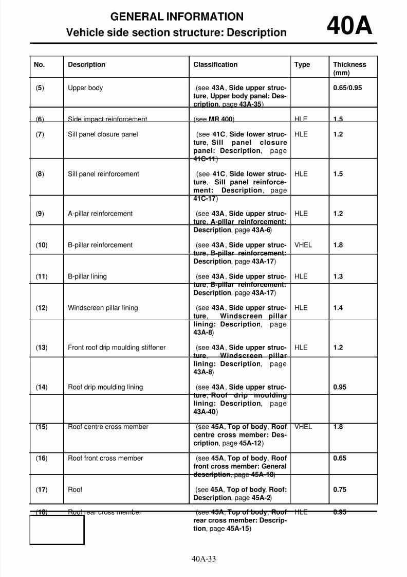
Vehicle side section structure: Description 40A
(5) Upper body (see 43A , Side upper struc-ture, Upper body panel: Des-cription, page 43A-35)
0.65/0.95
(6) Side impact reinforcement (see MR 400) HLE 1.5
(7) Sill panel closure panel (see 41C , Side lower struc-ture, Sill panel closurepanel: Description, page41C-11)
HLE 1.2
(8) Sill panel reinforcement (see 41C , Side lower struc-ture, Sill panel reinforce-ment: Description, page
41C-17)
HLE 1.5
(9) A-pillar reinforcement (see 43A , Side upper struc-ture, A-pillar reinforcement:Description, page 43A-6)
HLE 1.2
(10) B-pillar reinforcement (see 43A , Side upper struc-ture, B-pillar reinforcement:Description, page 43A-17)
VHEL 1.8
(11) B-pillar lining (see 43A , Side upper struc-ture, B-pillar reinforcement:Description, page 43A-17)
HLE 1.3
(12) Windscreen pillar lining (see 43A , Side upper struc-ture, Windscreen pillarlining: Description, page43A-8)
HLE 1.4
(13) Front roof drip moulding stiffener (see 43A , Side upper struc-ture, Windscreen pillarlining: Description, page43A-8)
HLE 1.2
(14) Roof drip moulding lining (see 43A , Side upper struc-ture, Roof drip moulding
lining: Description, page43A-40)
0.95
(15) Roof centre cross member (see 45A, Top of body, Roofcentre cross member: Des-cription, page 45A-12)
VHEL 1.8
(16) Roof front cross member (see 45A, Top of body, Rooffront cross member: Generaldescription, page 45A-10)
0.65
(17) Roof (see 45A, Top of body, Roof:Description, page 45A-2)
0.75
(18) Roof rear cross member (see 45A, Top of body, Roofrear cross member: Descrip-tion, page 45A-15)
HLE 0.95
No. Description Classification Type Thickness(mm)

8/21/2019 Panelwork 2009+
http://slidepdf.com/reader/full/panelwork-2009 39/31340A-34
GENERAL INFORMATION
Vehicle side section structure: Description 40A
C85 or S85
112468
No. Description Classification Type Thickness(mm)
(1) Body side front section (see 43A, Side upper struc-ture, A-pillar: Description,page 43A-2)
0.65/0.95
(2) Jacking point bridge piece (see 41C , Side lower struc-
ture, Sill panel: Description,page 41C-1)
VHEL 2
(3) Sill panel (see 41C , Side lower struc-ture, Sill panel: Description,page 41C-1)
0.65/0.95
(4) Double seal mounting (see 43A , Side upper struc-ture, A-pillar: Description,page 43A-2)
0.8
(5) Upper body (see 43A , Side upper struc-ture, Upper body panel: Des-cription, page 43A-35)
0.65/0.95
(6) Side impact reinforcement (see MR 400) HLE 1.5
8/21/2019 Panelwork 2009+
http://slidepdf.com/reader/full/panelwork-2009 40/31340A-35
GENERAL INFORMATION
Vehicle side section structure: Description 40A
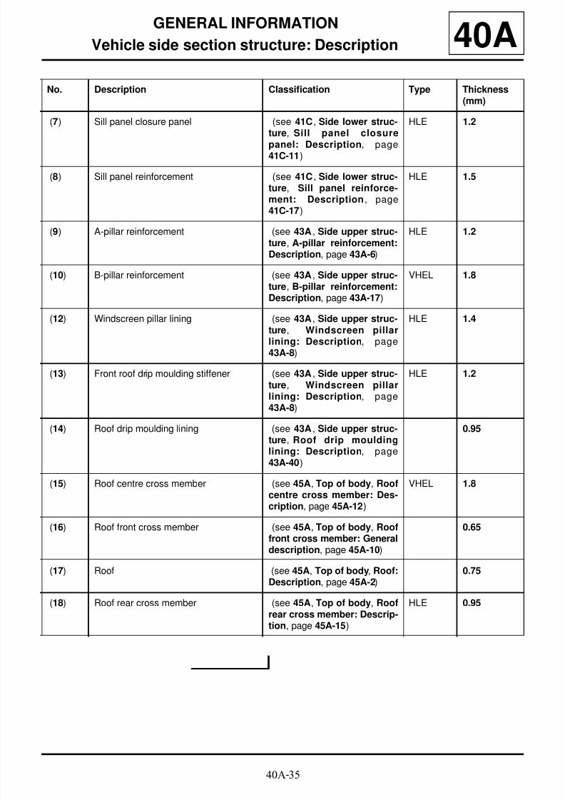
(7) Sill panel closure panel (see 41C , Side lower struc-ture, Sill panel closurepanel: Description, page41C-11)
HLE 1.2
(8) Sill panel reinforcement (see 41C , Side lower struc-ture, Sill panel reinforce-ment: Description, page41C-17)
HLE 1.5
(9) A-pillar reinforcement (see 43A , Side upper struc-ture, A-pillar reinforcement:Description, page 43A-6)
HLE 1.2
(10) B-pillar reinforcement (see 43A , Side upper struc-ture, B-pillar reinforcement:Description, page 43A-17)
VHEL 1.8
(12) Windscreen pillar lining (see 43A , Side upper struc-ture, Windscreen pillarlining: Description, page43A-8)
HLE 1.4
(13) Front roof drip moulding stiffener (see 43A , Side upper struc-ture, Windscreen pillarlining: Description, page43A-8)
HLE 1.2
(14) Roof drip moulding lining (see 43A , Side upper struc-ture, Roof drip mouldinglining: Description, page43A-40)
0.95
(15) Roof centre cross member (see 45A, Top of body, Roofcentre cross member: Des-cription, page 45A-12)
VHEL 1.8
(16) Roof front cross member (see 45A, Top of body, Rooffront cross member: Generaldescription, page 45A-10)
0.65
(17) Roof (see 45A, Top of body, Roof:Description, page 45A-2)
0.75
(18) Roof rear cross member (see 45A, Top of body, Roofrear cross member: Descrip-tion, page 45A-15)
HLE 0.95
No. Description Classification Type Thickness(mm)

8/21/2019 Panelwork 2009+
http://slidepdf.com/reader/full/panelwork-2009 41/31340A-36
GENERAL INFORMATION
Vehicle side section structure: Description 40A

8/21/2019 Panelwork 2009+
http://slidepdf.com/reader/full/panelwork-2009 42/31340A-37
GENERAL INFORMATION
Vehicle central section structure: Description 40ACENTRAL STRUCTURE
112110
No. Description Classification Type Thickness(mm)
(1) Centre floor, side section (see 41B , Centre lowerstructure, Central floor, sidesection: Description, page41B-11)
HLE 0.65/1.2
(2) Rear floor centre cross member (see 41D, Rear lower struc-
ture, Rear floor centre crossmember: Description, page41D-21)
HLE 1/1.2
(3) Front side member centre section (see 41A, Front lower struc-ture, F ront side member,central section: Descrip-tion, page 41A-12)
Very highyieldstrength
2
(4) Bulkhead side reinforcement (see 42A, Front upper struc-ture, Bulkhead side reinfor-c e m e n t : G e n e r a ldescription, page 42A-38)
Very highyieldstrength
1.6

8/21/2019 Panelwork 2009+
http://slidepdf.com/reader/full/panelwork-2009 43/31340A-38
GENERAL INFORMATION
Vehicle central section structure: Description 40A
(5) Bulkhead lower cross member (see 42A, Front upper struc-ture, Bulkhead lower crossmember: General descrip-tion, page 42A-37)
Very highyieldstrength
1.7
(6) Front cross member under front seat (see 41B , Centre lowerstructure, Front cross mem-ber under front seat: Des-cription, page 41B-6)
HLE 1.1
(7) Rear cross member under front seat (see 41B , Centre lowerstructure, Rear cross mem-ber under front seat: Des-cription, page 41B-8)
HLE 1.1
(8) Floor partition cross member (see 41D, Rear lower struc-ture, Rear floor, front sec-tion: Description, page 41D-4)
0.65
(9) Rear floor front cross member reinforce-ment
(see 41D, Rear lower struc-ture, Rear floor front crossmember stiffener: Descrip-tion, page 41D-19)
1.2
(10) Front section of rear floor (see 41D, Rear lower struc-ture, Rear floor, front sec-
tion: Description, page 41D-4)
0.65
(11) Windscreen aperture lower cross mem-ber closure panel
(see 42A, Front upper struc-ture, Windscreen aperturelower cross member clo-sure panel: Description,page 42A-35)
0.7
No. Description Classification Type Thickness(mm)

8/21/2019 Panelwork 2009+
http://slidepdf.com/reader/full/panelwork-2009 44/31340A-39
GENERAL INFORMATION
Vehicle structure rear section: Description 40AREAR STRUCTURE
B85
116930
No. Description Classification Type Thickness(mm)
(1) Rear wing panel (see 44A, Rear upper structure, Rear wingpanel: Description, page 44A-3)
0.75
(2) Outer rear wheel arch (see 44A, Rear upper structure, Outer rear
wheel arch: Description, page 44A-24)
0.65
(3) Body side rear lining (see 44A, Rear upper structure, Body siderear lining: Description, page 44A-30)
0.65/2
(4) Lights support lining (see 44A, Rear upper structure, Lights sup-port lining: Description, page 44A-18)
0.85/1
(5) Rear light mounting (see 44A , Rear upper structure, Rear lightssupport: Description, page 44A-15)
0.85/2
(6) Rear side memberassembly
(see 41D, Rear lower structure, Rear sidemember assembly: Description, page 41D-10)
HLE/ THLE
1.2/2
(7) Rear floor rear section (see 41D, Rear lower structure, Rear floorrear section: Description, page 41D-7)
0.65/1.5

8/21/2019 Panelwork 2009+
http://slidepdf.com/reader/full/panelwork-2009 45/31340A-40
GENERAL INFORMATION
Vehicle structure rear section: Description 40A
(8) Quarter panel upperreinforcement
(see 44A, Rear upper structure, Body siderear lining: Description, page 44A-30)
1.2
(9) Rear end panel lining (see 44A, Rear upper structure, Rear endpanel lining: Description, page 44A-44)
0.85/1.2
(10) Rear end panel (see 44A, Rear upper structure, Rear endpanel: Description, page 44A-41)
HLE 0.85
(11) Rear section of rearside member
(see 41D, Rear lower structure, Rear sidemember, rear section: Description, page 41D-16)
1.5/2
No. Description Classification Type Thickness(mm)
C85 or S85, and EQT LEVEL EA1 or EQT LEVELEA2 or EQT LEVEL EA3 or EQT LEVEL EA4 orEQT LEVEL EA5
116931

8/21/2019 Panelwork 2009+
http://slidepdf.com/reader/full/panelwork-2009 46/31340A-41
GENERAL INFORMATION
Vehicle structure rear section: Description 40A
No. Description Classification Type Thickness(mm)
(1) Jacking point bridgepiece (see 44A, Rear upper structure, Rear wingpanel: Description, page 44A-3) VHEL 2
(2) Rear wing panel (see 44A, Rear upper structure, Rear wingpanel: Description, page 44A-3)
0.75
(3) Rear airbag deflector (see 44A, Rear upper structure, Body siderear lining: Description, page 44A-30)
0.95
(4) Quarter panel strip rein-forcement
(see 43A, Side upper structure, B-pillar rein-forcement: Description, page 43A-17)
HLE 1.8
(5) Outer wheel arch (see 44A, Rear upper structure, Outer rear
wheel arch: Description, page 44A-24)
0.65
(6) Body side rear lining (see 44A, Rear upper structure, Body siderear lining: Description, page 44A-30)
0.65/2
(7) Lights support lining (see 44A, Rear upper structure, Lights sup-port lining: Description, page 44A-18)
0.85/1
(8) Rear light mounting (see 44A , Rear upper structure, Rear lightssupport: Description, page 44A-15)
0.85/2
(9) Rear side memberassembly
(see 41D, Rear lower structure, Rear sidemember assembly: Description, page 41D-10)
HLE/ THLE
1.2/2.8
(10) Rear section of rearside member
(see 41D, Rear lower structure, Rear sidemember, rear section: Description, page 41D-16)
1.5/2
(11) Rear floor rear section (see 41D, Rear lower structure, Rear floorrear section: Description, page 41D-7)
0.65/1.5
(12) Quarter panel upperreinforcement
(see 44A, Rear upper structure, Body siderear lining: Description, page 44A-30)
1.2
(13) Rear end panel lining (see 44A, Rear upper structure, Rear endpanel lining: Description, page 44A-44)
0.85/1.2
(14) Rear end panel (see 44A, Rear upper structure, Rear endpanel: Description, page 44A-41)
HLE 0.85

8/21/2019 Panelwork 2009+
http://slidepdf.com/reader/full/panelwork-2009 47/31340A-42
GENERAL INFORMATION
Vehicle structure rear section: Description 40A
C85, and EQT LEVEL SPORT
116929
No. Description Classification Type Thickness(mm)
(1) Jacking point bridgepiece
(see 44A, Rear upper structure, Rear wingpanel: Description, page 44A-3)
VHEL 2
(2) Rear wing panel (see 44A, Rear upper structure, Rear wingpanel: Description, page 44A-3)
0.75
(3) Rear airbag deflector (see 44A, Rear upper structure, Body siderear lining: Description, page 44A-30)
0.95
(4) Body side rear lining (see 44A, Rear upper structure, Body siderear lining: Description, page 44A-30)
0.65/2
(5) Lights support lining (see 44A, Rear upper structure, Lights sup-port lining: Description, page 44A-18)
0.85/1
(6) Rear light mounting (see 44A , Rear upper structure, Rear lightssupport: Description, page 44A-15)
0.85/2
(7) Outer rear wheel arch (see 44A, Rear upper structure, Outer rearwheel arch: Description, page 44A-24)
0.65

8/21/2019 Panelwork 2009+
http://slidepdf.com/reader/full/panelwork-2009 48/31340A-43
GENERAL INFORMATION
Vehicle structure rear section: Description 40A
(8) Quarter panel strip rein-forcement
(see 43A, Side upper structure, B-pillar rein-forcement: Description, page 43A-17)
HLE 1.8
(9) Rear side memberassembly
(see 41D, Rear lower structure, Rear sidemember assembly: Description, page 41D-10)
HLE/ THLE
1.2/2.8
(10) Rear section of rearside member
(see 41D, Rear lower structure, Rear sidemember, rear section: Description, page 41D-16)
1.5/2
(11) Rear floor rear section (see 41D, Rear lower structure, Rear floorrear section: Description, page 41D-7)
0.65/1.5
(12) Quarter panel upperreinforcement
(see 44A, Rear upper structure, Body siderear lining: Description, page 44A-30)
1.2
(13) Rear end panel lining (see 44A, Rear upper structure, Rear endpanel lining: Description, page 44A-44)
0.85/1.2
(14) Rear end panel (see 44A, Rear upper structure, Rear endpanel: Description, page 44A-41)
HLE 0.85
No. Description Classification Type Thickness(mm)
K85
126693
8/21/2019 Panelwork 2009+
http://slidepdf.com/reader/full/panelwork-2009 49/31340A-44
GENERAL INFORMATION
Vehicle structure rear section: Description 40A
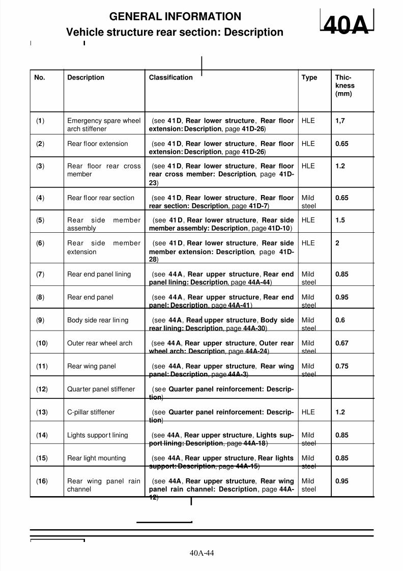
No. Description Classification Type Thic-kness(mm)
(1) Emergency spare wheelarch stiffener
(see 41D, Rear lower structure, Rear floorextension: Description, page 41D-26)
HLE 1,7
(2) Rear floor extension (see 41D, Rear lower structure, Rear floorextension: Description, page 41D-26)
HLE 0.65
(3) Rear floor rear crossmember
(see 41D, Rear lower structure, Rear floorrear cross member: Description, page 41D-
23)
HLE 1.2
(4) Rear floor rear section (see 41D, Rear lower structure, Rear floorrear section: Description, page 41D-7) Mildsteel 0.65
(5) Rear side memberassembly
(see 41D, Rear lower structure, Rear sidemember assembly: Description, page 41D-10)
HLE 1.5
(6) Rear side member
extension
(see 41D, Rear lower structure, Rear side
member extension: Description, page 41D-28)
HLE 2
(7) Rear end panel lining (see 44A , Rear upper structure, Rear endpanel lining: Description, page 44A-44)
Mildsteel
0.85
(8) Rear end panel (see 44A , Rear upper structure, Rear endpanel: Description, page 44A-41) Mildsteel 0.95
(9) Body side rear lining (see 44A, Rear upper structure, Body siderear lining: Description, page 44A-30)
Mildsteel
0.6
(10) Outer rear wheel arch (see 44A, Rear upper structure, Outer rearwheel arch: Description, page 44A-24)
Mildsteel
0.67
(11) Rear wing panel (see 44A, Rear upper structure, Rear wingpanel: Description, page 44A-3)
Mildsteel
0.75
(12) Quarter panel stiffener (see Quarter panel reinforcement: Descrip-
tion)
(13) C-pillar stiffener (see Quarter panel reinforcement: Descrip-tion)
HLE 1.2
(14) Lights suppor t lining (see 44A, Rear upper structure, Lights sup-port lining: Description, page 44A-18)
Mildsteel
0.85
(15) Rear light mounting (see 44A , Rear upper structure, Rear lightssupport: Description, page 44A-15)
Mildsteel
0.85
(16) Rear wing panel rainchannel
(see 44A, Rear upper structure, Rear wingpanel rain channel: Description, page 44A-
12)
Mildsteel
0.95
8/21/2019 Panelwork 2009+
http://slidepdf.com/reader/full/panelwork-2009 50/31340A-45
GENERAL INFORMATION
Vehicle structure rear section: Description 40A

8/21/2019 Panelwork 2009+
http://slidepdf.com/reader/full/panelwork-2009 51/31340A-46
GENERAL INFORMATIONStructure components to be positioned on body repair bench: Description 40A
I - PARTS REQUIRING THE USE OF A BODY JIGBENCH
(1) Radiator cross member support
(2) Centre floor front side cross member
(3) Front side member closure panel
(4) Front side member
(5) Engine stand
(6) Front half-unit
(7) Front wheel arch
(8) Engine tie-rod attachment
(9) Inner rear wheel arch
(10) Rear side member
(11) Rear section of rear side member
II - FRONT SUBFRAME REAR MOUNTING
The jig rests under the subframe mounting unit and iscentred in the threaded hole (A) .
112487
112250

8/21/2019 Panelwork 2009+
http://slidepdf.com/reader/full/panelwork-2009 52/31340A-47
GENERAL INFORMATIONStructure components to be positioned on body repair bench: Description 40A
It is used for replacing a complete front half unit.
III - REAR AXLE ASSEMBLY FRONT MOUNTING
The jig supports the underneath of the rear axle as-sembly mounting unit and is centred on square hole(B) and fixed on tapped hole (B1) of the rear axle bea-ring mounting.
It is used for replacing a rear side member assembly.
IV - FRONT SUB-FRAME FRONT MOUNTING
The jig supports the underneath of the front sub-framemounting and is centred on tapped hole (C) .
It is used when replacing:
- a complete front side member,
- a front half unit.
V - FRONT SHOCK ABSORBER UPPER MOUNTING
IMPORTANT
This/these point/s help(s) to ensure axle geometry.
112249
IMPORTANT
This/these point/s help(s) to ensure axle geometry.
112256
IMPORTANT
This/these point/s help(s) to ensure axle geometry.
112241

8/21/2019 Panelwork 2009+
http://slidepdf.com/reader/full/panelwork-2009 53/31340A-48
GENERAL INFORMATIONStructure components to be positioned on body repair bench: Description 40A
The jig supports the underneath of the shock absorbercup and is centred on the hole (F) of the shock absor-ber cup.
It is used when replacing:
- a wheel arch,
- a front half unit.
It is also used in straightening.
VI - ENGINE MOUNTING
The jig rests on the engine mounting and is centred inengine mounting securing holes (P1) and (P2) .
It is used with the mechanical components removed for
the replacement of:- a front half unit.
- the engine mounting.
VII - ENGINE TIE-ROD ATTACHMENT
The jig supports the engine tie-rod attachment moun-ting and is centred on hole (R) .
It is used with the mechanical components removed forthe replacement of:
- the engine tie-rod attachment,
- a front half unit.
VIII - RADIATOR MOUNTING CROSS MEMBERMOUNTING
The jig supports the underneath of the radiator crossmember and is centred in tapped hole (H1) .
IMPORTANT
This/these point/s help(s) to ensure axle geometry.
112242
112243
112257

8/21/2019 Panelwork 2009+
http://slidepdf.com/reader/full/panelwork-2009 54/31340A-49
GENERAL INFORMATIONStructure components to be positioned on body repair bench: Description 40A
It is used when replacing:
- the radiator cross member mounting,
- the front side member completely or partially,
- a half unit.
IX - FRONT IMPACT CROSS MEMBER MOUNTING
The jig rests vertically against the radiator cross mem-ber mounting unit and is centred in mounting holes (K)and (K1) .
It is used when replacing:
- the radiator cross member mounting,
- the front side member completely or partially,.
X - END OF REAR SIDE MEMBER
The jig rests vertically against the side member and iscentred in hole (J1) .
It is used for partially replacing a rear side member.
The jig rests under the rear side member and is cen-tred in hole (J) .
It should be used with the mechanical components inplace to realign a rear side member.
It is used with the mechanical components removed,under the same conditions, to replace the completerear side member.
112863
112098
112098
8/21/2019 Panelwork 2009+
http://slidepdf.com/reader/full/panelwork-2009 55/31340A-50
GENERAL INFORMATIONStructure components to be positioned on body repair bench: Description 40A
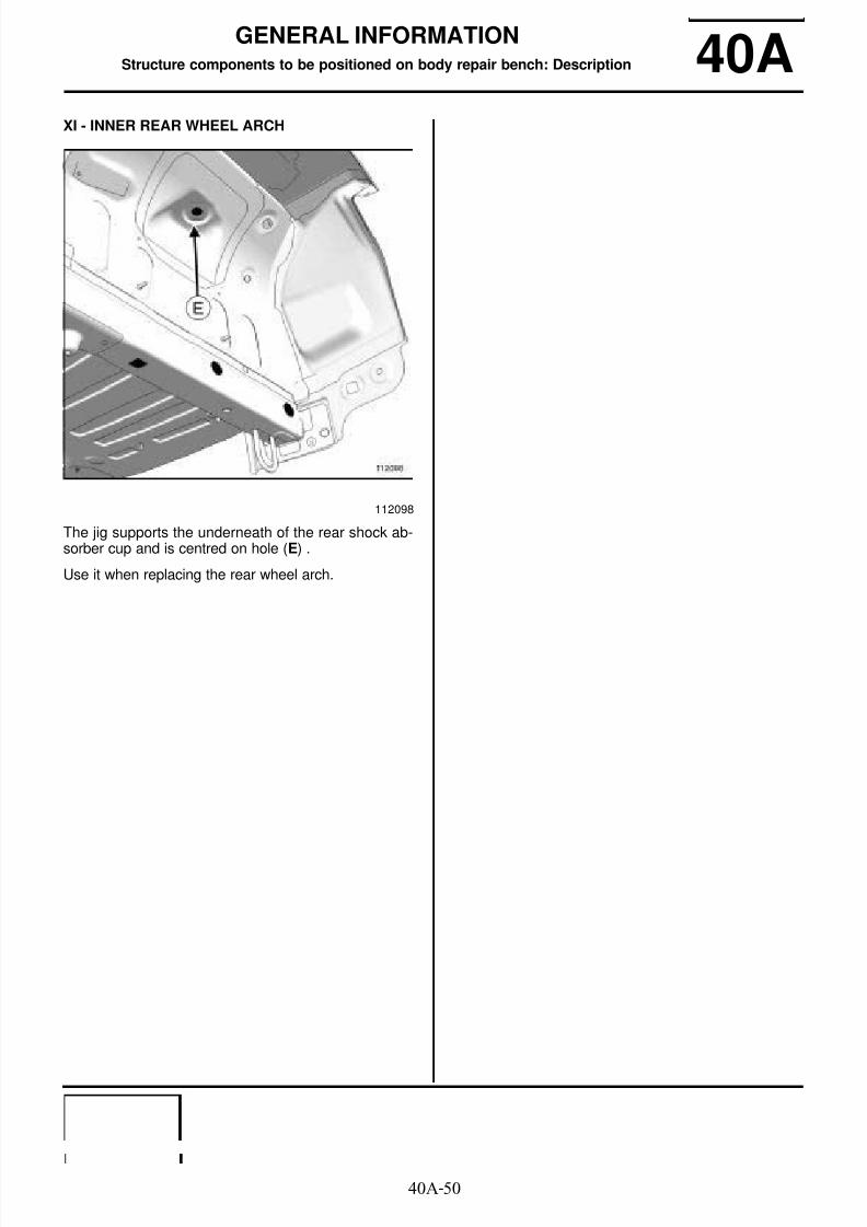
XI - INNER REAR WHEEL ARCH
The jig supports the underneath of the rear shock ab-sorber cup and is centred on hole (E) .
Use it when replacing the rear wheel arch.
112098
8/21/2019 Panelwork 2009+
http://slidepdf.com/reader/full/panelwork-2009 56/31340A-51
GENERAL INFORMATION
Hollow body parts inserts: Precautions for repair 40AThe expanding inserts ensure that the vehicle cavitiesare sealed and soundproofed. They react to the tempe-rature when the bodywork is immersed in the catapho-retic bath at the factory. These conditions cannot bereproduced on the bodywork.
As inserts are not recoverable, always replace expan-ding inserts.
The inserts supplied by the Parts Department areidentical to the original parts.
To obtain the same sealing and soundproofing proper-ties, carry out the following operations:
- clean the bonding surfaces with heptane,
- if necessary, block the holes in the insert using piecescut from a soundproofing pad.
- apply a bead of preformed trim sealing mastic aroundand inside the insert holes,
- fit the insert by compressing the mastic.
In some cases, it is possible to replace the accessiblepart of the insert only, which must be cut out of the re-placement part.
WARNING
Do not refit the part after compressing the bead.
When EGW welding, protect the inserts from spat-ter and heat dispersion.
For example, use a heat shield.

8/21/2019 Panelwork 2009+
http://slidepdf.com/reader/full/panelwork-2009 57/31341A-1
FRONT LOWER STRUCTURE
Lower front end cross member: General description 41A
DESIGN OF THE STRUCTURAL COMPONENT
A special feature of this part is that it is bolted to theends of the front side members via the radiator crossmember mounting support.
WARNING
The information contained in the following descri-bes the general repair procedure for all vehicles
having the same design for this part.
Before reading this general information, check thatthere are no special notes associated with this vehi-cle. These special notes are specified if necessaryin other parts of the sub-section dealing with thecomponent.
Note:
For a detailed description of a particular connec-
tion, see MR 400, 40A, General Information.
110517

8/21/2019 Panelwork 2009+
http://slidepdf.com/reader/full/panelwork-2009 58/31341A-2
FRONT LOWER STRUCTURE
Front impact cross member: Removal - Refitting 41A
I - REMOVAL
1 - REMOVAL PREPARATION OPERATION
a
- Remove the front bumper (see Front bumper: Re-
moval - Refitting) .
- Remove the headlights (see Halogen headlight:Removal - Refitting) (see Xenon headlight: Re-
moval - Refitting) .
2 - OPERATION FOR REMOVAL OF PART
CONCERNED
a Remove side mounting bolts (1) (three on either si-
de).
II - REFITTING
1 - REFITTING OPERATION FOR PARTCONCERNED
a Refit the side mounting bolts.
a
Torque tighten the side mounting bolts (1) (44Nm).
2 - FINAL OPERATION
a Refit the headlights (see Halogen headlight: Re-moval - Refitting) (see Xenon headlight: Remo-val - Refitting) .
- Refit the front bumper (see Front bumper: Remo-
val - Refitting) .
Tightening torquesm
side mounting bolts (1) 44 Nm
112025
WARNING
The cross member contributes to the structuralrigidity of the engine compartment. For this
reason, the tightening torque must be observedfollowing any operation.

8/21/2019 Panelwork 2009+
http://slidepdf.com/reader/full/panelwork-2009 59/31341A-3
FRONT LOWER STRUCTURE
Radiator support cross member: General description 41A
DESIGN OF THE STRUCTURAL COMPONENT
This steel part, which bolts onto the front axle subfra-me, combines two functions:
- distribution of front impact forces,
- radiator support cross member.
Note:
The information contained in the following descri-bes the general repair procedure for all vehicleshaving the same design for this part.
Before reading this general information, check thatthere are no special notes associated with this vehi-cle. These special notes will be specified if applica-ble in other parts of this subsection dealing with thepart.
Note:
For a detailed description of a particular connec-
tion, see MR 400.
110077
8/21/2019 Panelwork 2009+
http://slidepdf.com/reader/full/panelwork-2009 60/31341A-4
FRONT LOWER STRUCTURE
Radiator support cross member: Removal - Refitting 41A
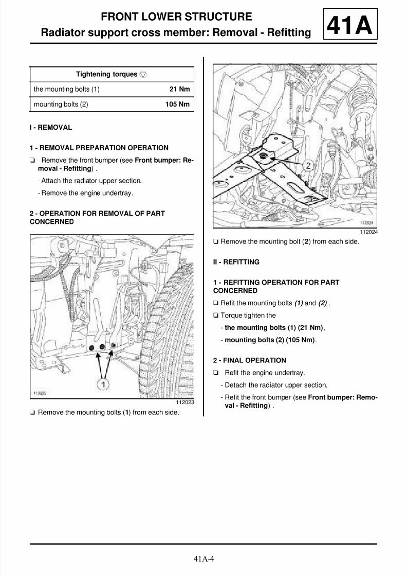
I - REMOVAL
1 - REMOVAL PREPARATION OPERATION
a Remove the front bumper (see Front bumper: Re-moval - Refitting) .
- Attach the radiator upper section.
- Remove the engine undertray.
2 - OPERATION FOR REMOVAL OF PARTCONCERNED
a Remove the mounting bolts (1) from each side.
a Remove the mounting bolt (2) from each side.
II - REFITTING
1 - REFITTING OPERATION FOR PARTCONCERNED
a Refit the mounting bolts (1) and (2) .
a Torque tighten the
- the mounting bolts (1) (21 Nm),
- mounting bolts (2) (105 Nm).
2 - FINAL OPERATION
a Refit the engine undertray.
- Detach the radiator upper section.
- Refit the front bumper (see Front bumper: Remo-
val - Refitting) .
Tightening torquesm
the mounting bolts (1) 21 Nm
mounting bolts (2) 105 Nm
112023
112024

8/21/2019 Panelwork 2009+
http://slidepdf.com/reader/full/panelwork-2009 61/31341A-5
FRONT LOWER STRUCTURE
Front side member: General description 41A
I - DESIGN OF THE STRUCTURAL COMPONENT
The special feature of this type of part is that it combi-nes the functions of front section and rear section ofthe front side member and that it is made of two diffe-rent kinds of panels of different thicknesses assembledby laser butt welding.
II - AREA TO BE CUT FOR PARTIALREPLACEMENT
1 - Cut 1:
This line shows the centre of the area in which it is pos-sible to carry out a partial replacement.
This operation allows you to access the inside of thehollow section of the structural element to straighten it.
In this case, the side member weld line must be stag-gered from that of its closure panel.
IMPORTANT
Use a repair bench to ensure the positioning of thepoints and the geometry of the axle assemblies.
Note:
The information contained in the following descri-bes the general repair procedure for all vehicleshaving the same design for this part.
Before reading the following general information,make sure that there are no special notes associa-ted with the vehicle. These special notes are speci-fied if necessary in other parts of the sub-section
dealing with the component.
Note:
For a detailed description of a particular connec-tion, see MR 400.
110509
110510
Note:
For the partial replacement of parts constituting asingle structural component, it is essential to stag-ger the welds of each of the components.

8/21/2019 Panelwork 2009+
http://slidepdf.com/reader/full/panelwork-2009 62/31341A-6
FRONT LOWER STRUCTURE
Front side member: General description 41A
2 - Cut 2:
The cut is made along the butt weld.
III - ASSEMBLY METHOD FOR A PARTIALREPLACEMENT
Only the connections which are specific to the partialreplacement by cutting are indicated.
130093
130094
130095
130096
WARNING
If the mating faces of the parts to be welded are notaccessible, make EGW plug welds to replace the
original resistance welds (see MR 400).

8/21/2019 Panelwork 2009+
http://slidepdf.com/reader/full/panelwork-2009 63/31341A-7
FRONT LOWER STRUCTURE
Front side member: General description 41AIf there are other issues regarding access to mating fa-ces, the various replacement options are described inthe basic instructions for structural bodywork repair(see MR 400).
Lines (3) and (4) on the diagram show a butt weld bycontinuous EGW welding.
Weld (4) along the butt weld line.
110511

8/21/2019 Panelwork 2009+
http://slidepdf.com/reader/full/panelwork-2009 64/31341A-8
FRONT LOWER STRUCTURE
Front side member: Description 41A
To replace this part, order the front side member ex-panding insert (A) .
The options for replacing this part are as follows:
- partial replacement of front end section,
- partial replacement of the front section.
I - COMPOSITION OF THE SPARE PART
II - PART FITTED
1 - Partial replacement of front end section (right-hand side)
(X1) = 180 mm
112615
IMPORTANT
The straightening bench must be used.
112116
No. Description Type Thic-kness(mm)
(1) Front side member HLE/ THLE
1.6 / 2.6
(2) Impact reinforce-ment
HLE 2
(3) Radiato r crossmember mounting
HLE 1.2 / 2.5
(4) Fro nt su bf ramemounting support
HLE 2
WARNING
Position this part correctly; its position is determi-ned by the position of the inner reinforcements.
112489

8/21/2019 Panelwork 2009+
http://slidepdf.com/reader/full/panelwork-2009 65/31341A-9
FRONT LOWER STRUCTURE
Front side member: Description 41A2 - Partial replacement of the front section
3 - Partial replacement of front end section (left-hand side)
(X2) = 60 mm
4 - Partial replacement of the front section
III - POSITIONING OF LOCAL ELECTRICALEARTHS
112490
WARNING
The cut is made along the line of the original buttweld.
112246
WARNING
Position this part correctly; its position is determi-ned by the position of the inner reinforcements.
112247
WARNING
The cut is made along the line of the original buttweld.
WARNING
- To avoid damaging the vehicle's electrical andelectronic components, be sure to disconnect theearths of any wiring near the weld zone.
- The welding machine earth must be placed asclose as possible to the weld zone.

8/21/2019 Panelwork 2009+
http://slidepdf.com/reader/full/panelwork-2009 66/31341A-10
FRONT LOWER STRUCTURE
Front side member: Description 41A
112244
112488

8/21/2019 Panelwork 2009+
http://slidepdf.com/reader/full/panelwork-2009 67/31341A-11
FRONT LOWER STRUCTURE
Front side member, central section: General description 41A
DESIGN OF THE STRUCTURAL COMPONENT
This is a basic part; its only function is that of front sidemember, centre section.
IMPORTANT
Use a repair bench to ensure the positioning of thepoints and the geometry of the axle assemblies.
Note:
The information contained in the following descri-bes the general repair procedure for all vehicleshaving the same design for this part.
Before reading the following general information,make sure that there are no special notes associa-ted with the vehicle. These special notes are speci-fied if necessary in other parts of the sub-section
dealing with the component.
Note:
For a detailed description of a particular connec-
tion, see MR 400.
112710
WARNINGIf the mating faces of the parts to be welded are notaccessible, make EGW plug welds to replace theoriginal resistance welds (see MR 400).

8/21/2019 Panelwork 2009+
http://slidepdf.com/reader/full/panelwork-2009 68/31341A-12
FRONT LOWER STRUCTURE
Front side member, central section: Description 41A
There is only one way of replacing this part:
- Complete replacement:
I - COMPOSITION OF THE SPARE PART
II - PART FITTED
112710
112115
No. Description Type Thic-kness
(mm)
(1) Centre side mem-ber
Veryhighyield
strength
2
(2) Centre side mem-ber reinforcement
VHEL 2.5
WARNING
- To avoid damaging the vehicle's electrical and
electronic components, be sure to disconnect theearths of any wiring near the weld zone.
- The welding machine earth must be placed asclose as possible to the weld zone.
112677
IMPORTANT
For welded connections in three thicknesses, thespot welds on the part replaced should be made inthe same place as for the original joint to retain itsmechanical properties.

8/21/2019 Panelwork 2009+
http://slidepdf.com/reader/full/panelwork-2009 69/31341A-13
FRONT LOWER STRUCTURE
Front section of front side member closure panel: General description 41A
I - DESIGN OF THE STRUCTURAL COMPONENT
The special feature of this type of part is that it combi-nes the functions of both the front section and rear sec-tion of the front side member closure panel and that itis made of two different kinds of panels of different thic-knesses assembled by laser butt welding.
II - AREA TO BE CUT FOR PARTIALREPLACEMENT
For removal of the side member (see 41A, Front lowerstructure, Front side member: Description, page41A-8) .
1 - Cut 1:
This line shows the centre of the area in which it is pos-sible to carry out a partial replacement.
This operation allows you to access the inside of thehollow section of the structural component to straigh-ten it.
IMPORTANT
Use a repair bench to ensure the positioning of thepoints and the geometry of the axle assemblies.
Note:
The information contained in the following descri-bes the general repair procedure for all vehicleshaving the same design for this part.
Before reading the following general information,make sure that there are no special notes associa-ted with the vehicle. These special notes are speci-fied if necessary in other parts of the sub-section
dealing with the component.
Note:
For a detailed description of a particular connec-tion, see MR 400.
130106
Note:
For the partial replacement of parts constituting asingle structural component, it is essential to stag-ger the welds of each of the components.
110513

8/21/2019 Panelwork 2009+
http://slidepdf.com/reader/full/panelwork-2009 70/31341A-14
FRONT LOWER STRUCTURE
Front section of front side member closure panel: General description 41A
2 - Cut 2:
The cut must be made on the splice.
III - ASSEMBLY INSTRUCTIONS FOR A PARTIAL
REPLACEMENT
In this case, the side member weld line must be stag-gered from that of its closure panel.
Only the connections which are specific to the partialreplacement by cutting are indicated.
If there are other issues regarding access to mating fa-
ces, the various replacement options are described inthe basic instructions for structural bodywork repair(see MR 400).
Lines (3) and (4) on the diagram show a butt weld bycontinuous EGW welding.
Weld (4) along the butt weld line.
130108
130109
Note:
For the partial replacement of parts constituting asingle structural component, it is essential to stag-ger the welds of each of the components.
WARNING
If the mating faces of the parts to be welded are notaccessible, make EGW plug welds to replace theoriginal resistance welds (see MR 400).
110514
8/21/2019 Panelwork 2009+
http://slidepdf.com/reader/full/panelwork-2009 71/31341A-15
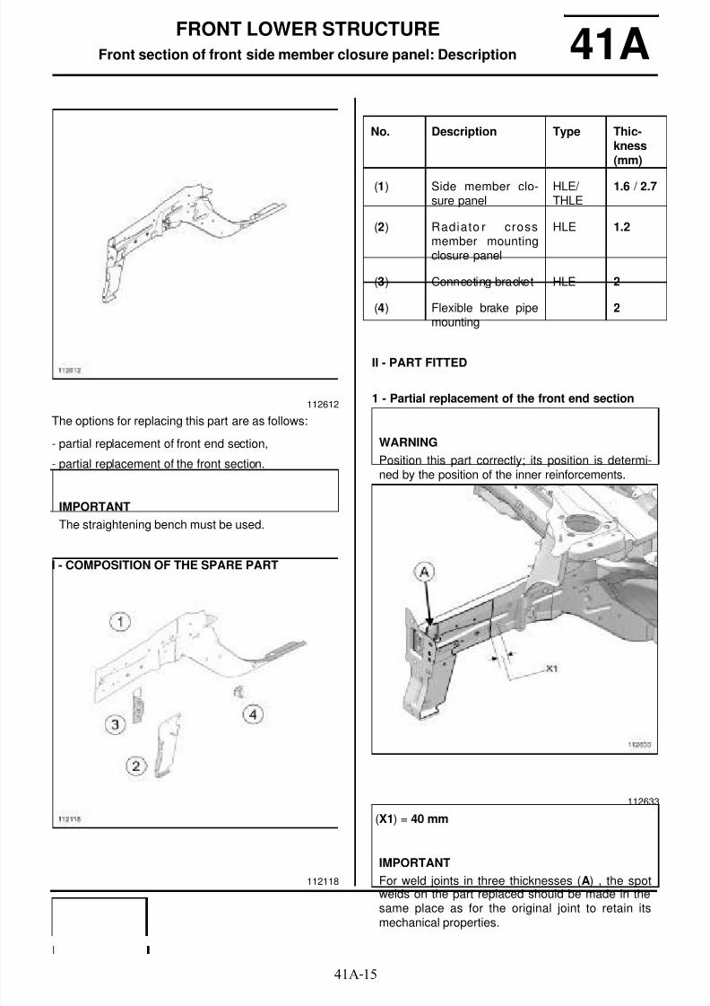
FRONT LOWER STRUCTURE
Front section of front side member closure panel: Description 41A
The options for replacing this part are as follows:
- partial replacement of front end section,
- partial replacement of the front section.
I - COMPOSITION OF THE SPARE PART
II - PART FITTED
1 - Partial replacement of the front end section
(X1) = 40 mm
112612
IMPORTANT
The straightening bench must be used.
112118
No. Description Type Thic-kness(mm)
(1) Side member clo-sure panel
HLE/ THLE
1.6 / 2.7
(2) Radiato r crossmember mountingclosure panel
HLE 1.2
(3) Connecting bracket HLE 2
(4) Flexible brake pipemounting
2
WARNING
Position this part correctly; its position is determi-ned by the position of the inner reinforcements.
112633
IMPORTANT
For weld joints in three thicknesses (A) , the spotwelds on the part replaced should be made in thesame place as for the original joint to retain itsmechanical properties.
8/21/2019 Panelwork 2009+
http://slidepdf.com/reader/full/panelwork-2009 72/31341A-16
FRONT LOWER STRUCTURE
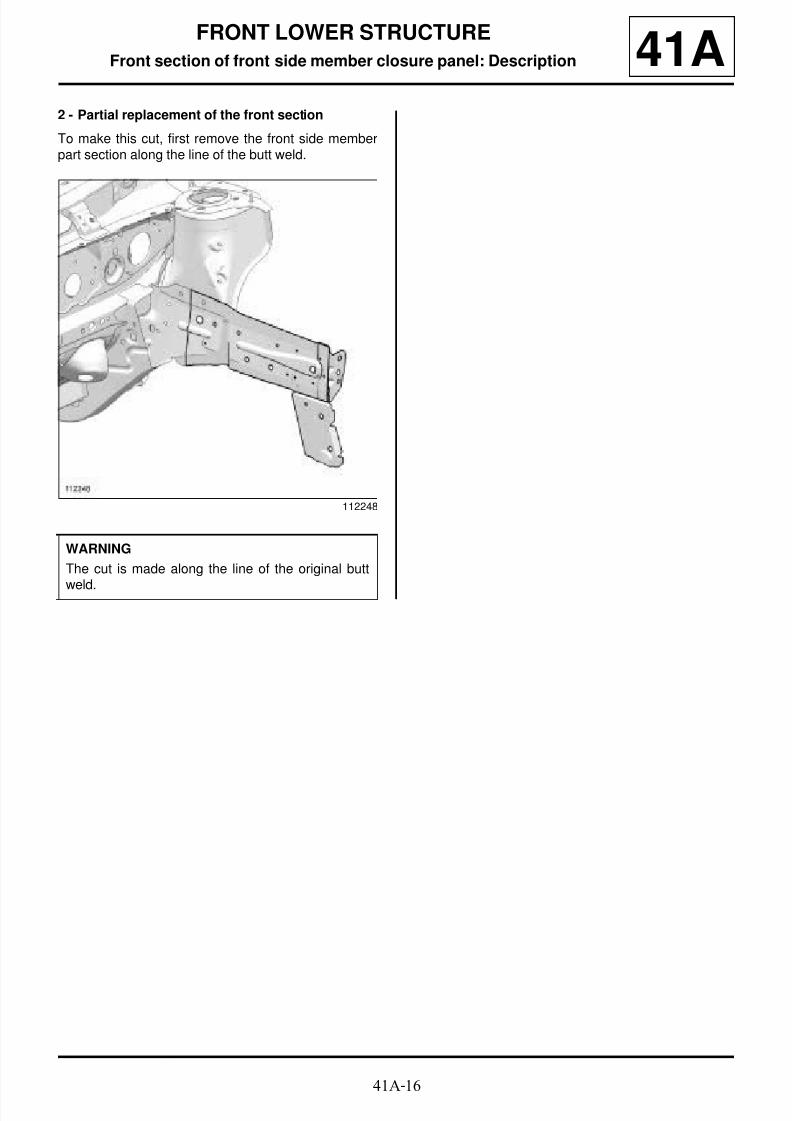
Front section of front side member closure panel: Description 41A2 - Partial replacement of the front section
To make this cut, first remove the front side memberpart section along the line of the butt weld.
112248
WARNING
The cut is made along the line of the original butt
weld.

8/21/2019 Panelwork 2009+
http://slidepdf.com/reader/full/panelwork-2009 73/31341A-17
FRONT LOWER STRUCTURE
Battery tray support: General description 41A
DESIGN OF THE STRUCTURAL COMPONENT
This part is bolted to the front side member. It is madeof plastic. The type of plastic is indicated on the part it-self.
Note:
The information contained in the following descri-bes the general repair procedure for all vehicleshaving the same design for this part. Before readingthe following general information, make sure thatthere are no special notes associated with the vehi-cle. These special notes are specified if necessaryin other parts of the sub-section dealing with thecomponent.
Note:
For a detailed description of a particular connec-tion, see MR 400.
8/21/2019 Panelwork 2009+
http://slidepdf.com/reader/full/panelwork-2009 74/31341A-18
FRONT LOWER STRUCTURE
Radiator cross member mounting: General description 41A
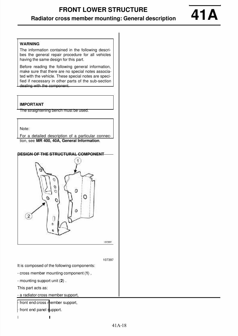
DESIGN OF THE STRUCTURAL COMPONENT
It is composed of the following components:
- cross member mounting component (1) ,
- mounting support unit (2) .
This part acts as:
- a radiator cross member support,
- front end cross member support,
- front end panel support.
WARNING
The information contained in the following descri-bes the general repair procedure for all vehicles
having the same design for this part.
Before reading the following general information,make sure that there are no special notes associa-ted with the vehicle. These special notes are speci-fied if necessary in other parts of the sub-sectiondealing with the component.
IMPORTANT
The straightening bench must be used.
Note:
For a detailed description of a particular connec-tion, see MR 400, 40A, General Information.
107397

8/21/2019 Panelwork 2009+
http://slidepdf.com/reader/full/panelwork-2009 75/31341A-19
FRONT LOWER STRUCTURE
Radiator cross member support: Description 41A
There is only one way of replacing this part:
- complete replacement.
I - COMPOSITION OF THE SPARE PART
II - PART FITTED
112613
IMPORTANT
A straightening bench is essential when simulta-neously replacing the left-hand and right-hand
parts.
112121
No. Description Type Thic-kness(mm)
(1) Radiato r crossmember mountingclosure panel
HLE 2.5
(2) Radiato r crossmember mountingunit
HLE 1.2
112245
WARNING
If the spot welds cannot be made as they were ori-ginally using an electrical spot welding machine,they should be replaced with plug welds after holeshave been drilled in the first panel.

8/21/2019 Panelwork 2009+
http://slidepdf.com/reader/full/panelwork-2009 76/31341A-20
FRONT LOWER STRUCTURE
Front mounting of front sub-frame: General description 41A
DESIGN OF THE STRUCTURAL COMPONENT
1 - Right-hand side
The subframe mounting (1) is attached to the sidemember.
2 - Left side
The mounting is integrated into the side member.
IMPORTANT
Use a repair bench to ensure the positioning of thepoints and the geometry of the axle assemblies.
Note:
The information contained in the following descri-bes the general repair procedure for all vehicleshaving the same design for this part.
Before reading the following general information,make sure that there are no special notes associa-ted with the vehicle. These special notes are speci-fied if necessary in other parts of the sub-section
dealing with the component.
Note:
For a detailed description of a particular connec-tion, see MR 400.
110509

8/21/2019 Panelwork 2009+
http://slidepdf.com/reader/full/panelwork-2009 77/31341A-21
FRONT LOWER STRUCTURE
Engine mounting: General description 41A
DESIGN OF THE STRUCTURAL COMPONENT
This is a basic part; it only functions as an enginemounting.
IMPORTANT
Use a repair bench to ensure the positioning of thepoints and the geometry of the axle assemblies.
Note:
The information contained in the following descri-bes the general repair procedure for all vehicleshaving the same design for this part.
Before reading this general information, check thatthere are no special notes associated with this vehi-cle. These special notes will be specified if applica-ble in other parts of this subsection dealing with the
part.
Note:
For a detailed description of a particular connec-tion, see MR 400.
110587
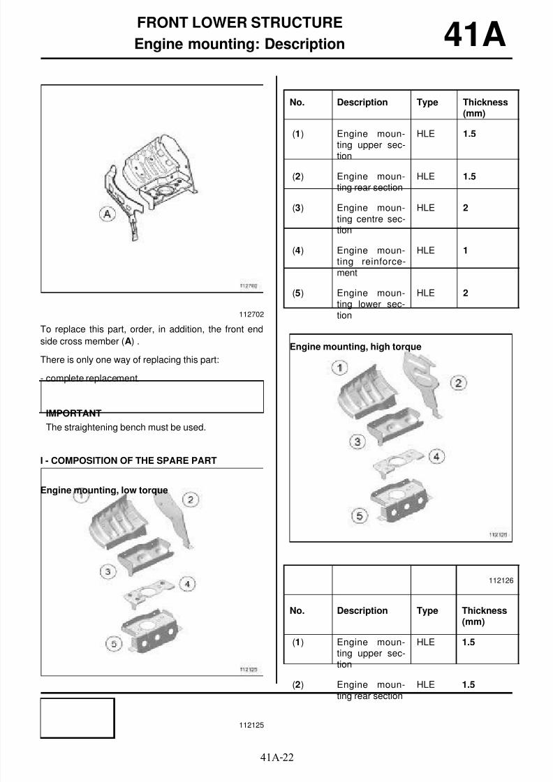
8/21/2019 Panelwork 2009+
http://slidepdf.com/reader/full/panelwork-2009 78/31341A-22
FRONT LOWER STRUCTURE
Engine mounting: Description 41A
To replace this part, order, in addition, the front end
side cross member (A) .
There is only one way of replacing this part:
- complete replacement.
I - COMPOSITION OF THE SPARE PART
Engine mounting, low torque
Engine mounting, high torque
112702
IMPORTANT
The straightening bench must be used.
112125
No. Description Type Thickness(mm)
(1) Engine moun-ting upper sec-tion
HLE 1.5
(2) Engine moun-ting rear section
HLE 1.5
(3) Engine moun-ting centre sec-tion
HLE 2
(4) Engine moun-ting reinforce-
ment
HLE 1
(5) Engine moun-ting lower sec-tion
HLE 2
112126
No. Description Type Thickness(mm)
(1) Engine moun-ting upper sec-tion
HLE 1.5
(2) Engine moun-ting rear section
HLE 1.5

8/21/2019 Panelwork 2009+
http://slidepdf.com/reader/full/panelwork-2009 79/31341A-23
FRONT LOWER STRUCTURE
Engine mounting: Description 41A
II - PART FITTED
Engine mounting, low torque
Engine mounting, high torque
III - POSITIONING OF LOCAL ELECTRICALEARTHS
For the earth stud fitting procedure (see 40A, Generalinformation, Earths on the body: List and locationof components, page 40A-23)
(3) Engine moun-ting centre sec-tion
HLE 2
(4) Engine moun-ting reinforce-ment
HLE 1
(5) Engine moun-ting lower sec-tion
HLE 2
112491
No. Description Type Thickness(mm)
112492
WARNING
If the spot welds cannot be made as they were ori-ginally using an electrical spot welding machine,they should be replaced with plug welds after holeshave been drilled in the first panel.
112488

8/21/2019 Panelwork 2009+
http://slidepdf.com/reader/full/panelwork-2009 80/31341A-24
FRONT LOWER STRUCTURE
Front half unit: Description 41ALeft-hand side
Right-hand side
To replace this part, order the heater bulkhead reinfor-cement (A) and the side member expanding insert (B) .
There is only one way of replacing this part:
- complete replacement.
I - COMPOSITION OF THE SPARE PART
Left side
112592
112591
IMPORTANT
The straightening bench must be used.
112123
No. Description Type Thickness(mm)
(1) Front side mem-
ber
HLE/
THLE
1.6 / 2.6
(2) Wheel arch HLE 1.2 / 2
(3) Side memberclosure panel
HLE/ THLE
1.6 / 2.7
(4) Centre floor frontside cross mem-ber
HLE 1
(5) Front end sidecross member
HLE 1.5

8/21/2019 Panelwork 2009+
http://slidepdf.com/reader/full/panelwork-2009 81/31341A-25
FRONT LOWER STRUCTURE
Front half unit: Description 41ARight-hand side, low torque Right-hand side, high torque
II - PART FITTED
112122
No. Description Type Thic-kness(mm)
(6) Wheel arch HLE 1.2 / 2
(7) Engine stand HLE 1.5 / 2
(8) Front end sidecross member
HLE 1.5
(9) Side memberclosure panel
HLE/ THLE
1.6 / 2.7
(10) Front side mem-ber
HLE/ THLE
1.6 / 2.6
(11) Ce nt re floorfront side cross
member
HLE 1
112124
No. Description Type Thickness(mm)
(6) Wheel arch HLE 1.2 / 2
(7) Engine stand HLE 1.5 / 2
(8) Front end sidecross member
HLE 1.5
(9) Side memberclosure panel
HLE/ THLE
1.6 / 2.7
(10) Front side mem-ber
HLE/ THLE
1.6 / 2.6
(11) Ce nt re floorfront side crossmember
HLE 1
IMPORTANT
For welded connections in three thicknesses, thespot welds on the part replaced should be made inthe same place as for the original joint to retain itsmechanical properties.

8/21/2019 Panelwork 2009+
http://slidepdf.com/reader/full/panelwork-2009 82/31341A-26
FRONT LOWER STRUCTURE
Front half unit: Description 41A
Front half unit, low torque
Front half unit, high torque
III - POSITIONING OF LOCAL ELECTRICAL
EARTHS
WARNING
If the spot welds cannot be made as they were ori-ginally using an electrical spot welding machine,
they should be replaced with plug welds after holeshave been drilled in the first panel.
112675
112676
112728
Note:
The heater bulkhead reinforcement is availableseparately (see Parts Catalogue).
112244

8/21/2019 Panelwork 2009+
http://slidepdf.com/reader/full/panelwork-2009 83/31341A-27
FRONT LOWER STRUCTURE
Front half unit: Description 41A
112251
112488
IMPORTANT
To avoid damaging the vehicle's electric and elec-
tronic components, the battery and the earths ofany wiring harness near the weld area must be dis-connected.
The earth of the welding machine must be placedas close as possible to the weld area.

8/21/2019 Panelwork 2009+
http://slidepdf.com/reader/full/panelwork-2009 84/31341A-28
FRONT LOWER STRUCTURE
Sub-frame rear mounting: General description 41A
DESIGN OF THE STRUCTURAL COMPONENT
The front sub-frame rear mounting (1) is welded to thefront half unit.
IMPORTANT
Use a repair bench to ensure the positioning of thepoints and the geometry of the axle assemblies.
Note:
The information contained in the following descri-bes the general repair procedure for all vehicleshaving the same design for this part.
Before reading this general information, check thatthere are no special notes associated with this vehi-cle. These special notes will be specified if applica-ble in other parts of this subsection dealing with the
part.
Note:
For a detailed description of a particular connec-tion, see MR 400.
110489

8/21/2019 Panelwork 2009+
http://slidepdf.com/reader/full/panelwork-2009 85/31341A-29
FRONT LOWER STRUCTURE
Front towing ring: General description 41A
DESIGN OF THE STRUCTURAL COMPONENT
This part is welded to the right hand unit (1) of the fron-tal impact cross member and therefore cannot be re-placed. Replace the cross member unit if the thread isdamaged.
Note:
The information contained in the following descri-bes the general repair procedure for all vehicleshaving the same design for this part.
Before reading this general information, check thatthere are no special notes associated with this vehi-cle. These special notes will be specified if applica-ble in other parts of this subsection dealing with thepart.
Note:
For a detailed description of a particular connec-
tion, see MR 400.
110108
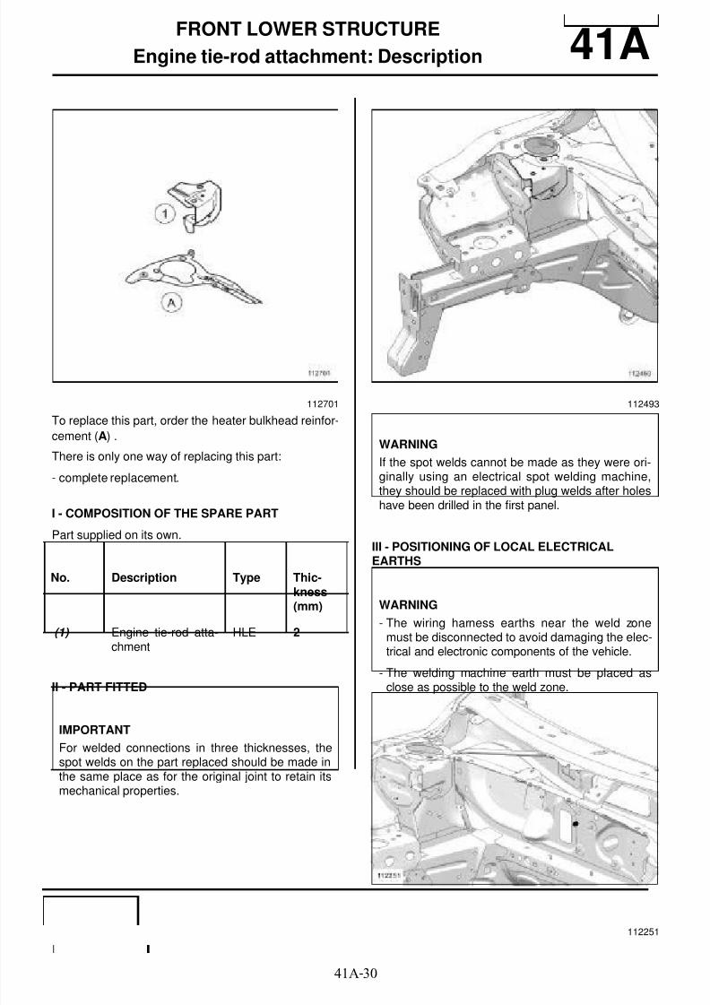
8/21/2019 Panelwork 2009+
http://slidepdf.com/reader/full/panelwork-2009 86/31341A-30
FRONT LOWER STRUCTURE
Engine tie-rod attachment: Description 41A
To replace this part, order the heater bulkhead reinfor-
cement (A) .
There is only one way of replacing this part:
- complete replacement.
I - COMPOSITION OF THE SPARE PART
Part supplied on its own.
II - PART FITTED
III - POSITIONING OF LOCAL ELECTRICALEARTHS
112701
No. Description Type Thic-kness(mm)
(1) Engine tie-rod atta-chment
HLE 2
IMPORTANT
For welded connections in three thicknesses, thespot welds on the part replaced should be made inthe same place as for the original joint to retain itsmechanical properties.
112493
WARNING
If the spot welds cannot be made as they were ori-ginally using an electrical spot welding machine,they should be replaced with plug welds after holeshave been drilled in the first panel.
WARNING
- The wiring harness earths near the weld zonemust be disconnected to avoid damaging the elec-trical and electronic components of the vehicle.
- The welding machine earth must be placed asclose as possible to the weld zone.
112251
8/21/2019 Panelwork 2009+
http://slidepdf.com/reader/full/panelwork-2009 87/31341A-31
FRONT LOWER STRUCTURE
Engine tie-rod attachment: Description 41A
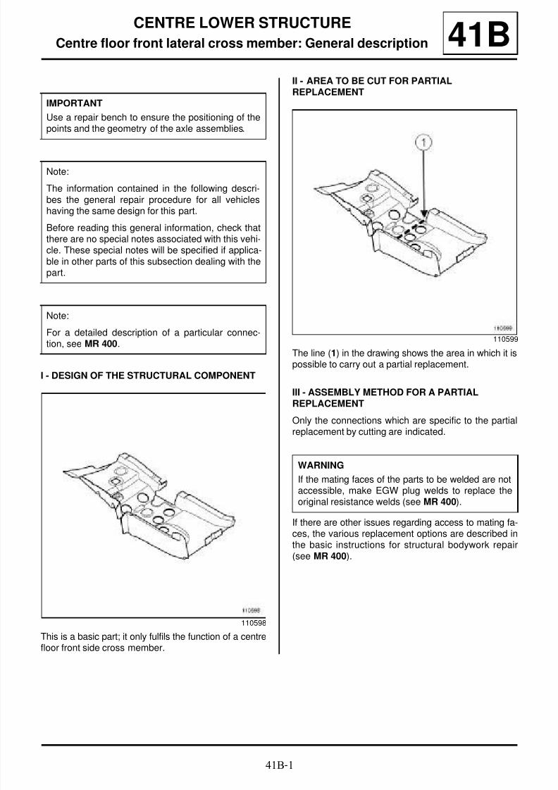
8/21/2019 Panelwork 2009+
http://slidepdf.com/reader/full/panelwork-2009 88/31341B-1
CENTRE LOWER STRUCTURE
Centre floor front lateral cross member: General description 41B
I - DESIGN OF THE STRUCTURAL COMPONENT
This is a basic part; it only fulfils the function of a centrefloor front side cross member.
II - AREA TO BE CUT FOR PARTIALREPLACEMENT
The line (1) in the drawing shows the area in which it ispossible to carry out a partial replacement.
III - ASSEMBLY METHOD FOR A PARTIALREPLACEMENT
Only the connections which are specific to the partialreplacement by cutting are indicated.
If there are other issues regarding access to mating fa-ces, the various replacement options are described inthe basic instructions for structural bodywork repair
(see MR 400).
IMPORTANT
Use a repair bench to ensure the positioning of thepoints and the geometry of the axle assemblies.
Note:
The information contained in the following descri-bes the general repair procedure for all vehicleshaving the same design for this part.
Before reading this general information, check thatthere are no special notes associated with this vehi-cle. These special notes will be specified if applica-ble in other parts of this subsection dealing with the
part.
Note:
For a detailed description of a particular connec-tion, see MR 400.
110598
110599
WARNING
If the mating faces of the parts to be welded are notaccessible, make EGW plug welds to replace theoriginal resistance welds (see MR 400).

8/21/2019 Panelwork 2009+
http://slidepdf.com/reader/full/panelwork-2009 89/31341B-2
CENTRE LOWER STRUCTURE
Centre floor front lateral cross member: General description 41B
Line (3) on the drawing shows a butt weld by conti-
nuous EGW welding.
110600
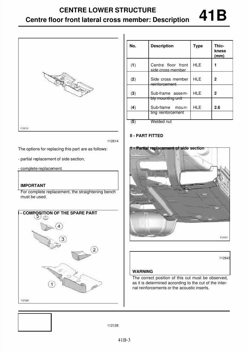
8/21/2019 Panelwork 2009+
http://slidepdf.com/reader/full/panelwork-2009 90/31341B-3
CENTRE LOWER STRUCTURE
Centre floor front lateral cross member: Description 41B
The options for replacing this part are as follows:
- partial replacement of side section,
- complete replacement.
I - COMPOSITION OF THE SPARE PART
II - PART FITTED
1 - Partial replacement of side section
112614
IMPORTANT
For complete replacement, the straightening benchmust be used.
112128
No. Description Type Thic-kness(mm)
(1) Centre floor frontside cross member
HLE 1
(2) Side cross memberreinforcement
HLE 2
(3) Sub-frame assem-bly mounting unit
HLE 2
(4) Sub-frame moun-ting reinforcement
HLE 2.6
(5) Welded nut
112643
WARNING
The correct position of this cut must be observed,as it is determined according to the cut of the inter-nal reinforcements or the acoustic inserts.

8/21/2019 Panelwork 2009+
http://slidepdf.com/reader/full/panelwork-2009 91/31341B-4
CENTRE LOWER STRUCTURE
Centre floor front lateral cross member: Description 41B2 - Complete replacement
112644
IMPORTANT
For welded connections in three thicknesses, thespot welds on the part replaced should be made inthe same place as for the original joint to retain itsmechanical properties.
WARNING
If the spot welds cannot be made as they were ori-ginally using an electrical spot welding machine,they should be replaced with plug welds after holeshave been drilled in the first panel.

8/21/2019 Panelwork 2009+
http://slidepdf.com/reader/full/panelwork-2009 92/31341B-5
CENTRE LOWER STRUCTURE
Front cross member under front seat: General description 41B
DESIGN OF THE STRUCTURAL COMPONENT
This is a basic part; its function is to secure the frontsection of the front seat and to stiffen the bodywork inthe event of a side impact.
Note:
The information contained in the following descri-bes the general repair procedure for all vehicleshaving the same design for this part.
Before reading this general information, check thatthere are no special notes associated with this vehi-cle. These special notes will be specified if applica-ble in other parts of this subsection dealing with thepart.
Note:
For a detailed description of a particular connec-
tion, see MR 400.
110507
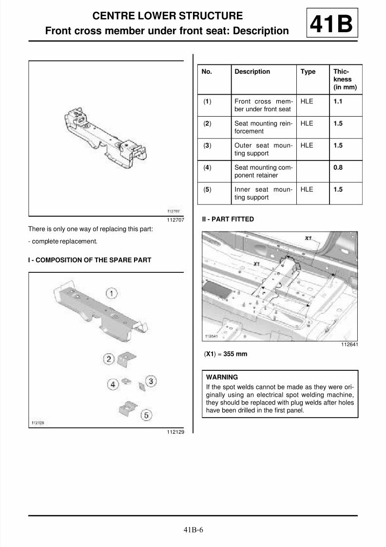
8/21/2019 Panelwork 2009+
http://slidepdf.com/reader/full/panelwork-2009 93/31341B-6
CENTRE LOWER STRUCTURE
Front cross member under front seat: Description 41B
There is only one way of replacing this part:
- complete replacement.
I - COMPOSITION OF THE SPARE PART
II - PART FITTED
(X1) = 355 mm
112707
112129
No. Description Type Thic-kness(in mm)
(1) Front cross mem-ber under front seat
HLE 1.1
(2) Seat mounting rein-forcement
HLE 1.5
(3) Outer seat moun-ting support
HLE 1.5
(4) Seat mounting com-ponent retainer
0.8
(5) Inner seat moun-ting support HLE 1.5
112641
WARNING
If the spot welds cannot be made as they were ori-ginally using an electrical spot welding machine,they should be replaced with plug welds after holeshave been drilled in the first panel.

8/21/2019 Panelwork 2009+
http://slidepdf.com/reader/full/panelwork-2009 94/31341B-7
CENTRE LOWER STRUCTURE
Rear cross member under front seat: General description 41B
DESIGN OF THE STRUCTURAL COMPONENT
This is a basic part. It serves as a mounting for the rearpart of the front seat and to rigidify the body in theevent of a side impact.
Note:
The information contained in the following descri-bes the general repair procedure for all vehicleshaving the same design for this part.
Before reading this general information, check thatthere are no special notes associated with this vehi-cle. These special notes will be specified if applica-ble in other parts of this subsection dealing with thepart.
Note:
For a detailed description of a particular connec-
tion, see MR 400.
110499

8/21/2019 Panelwork 2009+
http://slidepdf.com/reader/full/panelwork-2009 95/31341B-8
CENTRE LOWER STRUCTURE
Rear cross member under front seat: Description 41B
There is only one way of replacing this part:
- complete replacement.
I - COMPOSITION OF THE SPARE PART
II - PART FITTED
(X1) = 355 mm
112708
112130
No. Description Type Thic-kness(mm)
(1) Rear cross mem-ber under front seat
HLE 1.1
(2) Seat mounting rein-forcement
HLE 1.5
(3) Seat mounting com-ponent retainer
0.8
(4) Inner seat moun-ting support
HLE 1.5
112642
WARNING
If the spot welds cannot be made as they were ori-ginally using an electrical spot welding machine,
they should be replaced with plug welds after holeshave been drilled in the first panel.

8/21/2019 Panelwork 2009+
http://slidepdf.com/reader/full/panelwork-2009 96/31341B-9
CENTRE LOWER STRUCTURE
Centre floor, side section: General description 41B
I - DESIGN OF THE STRUCTURAL COMPONENT
The special feature of this type of part is that it combi-nes the functions of the centre floor side section andthe sill panel closure panel and it is made of two diffe-rent kinds of panel of different thicknesses assembledby laser butt welding.
II - AREA TO BE CUT FOR PARTIALREPLACEMENT
These cutting lines show the area in which it is possibleto carry out a partial replacement of the centre floorside section.
Cut 1, 2 and 3:
- cut (1) affects the partial replacement of the centrefloor side section,
- cuts (1) and (2) affect the partial replacement of therear section of the centre floor side section
- cuts (1) and (3) affect the partial replacement of thefront section of the centre floor side section.
III - ASSEMBLY METHOD FOR A PARTIAL
REPLACEMENT
Only the connections which are specific to the partialreplacement by cutting are indicated.
If there are other issues regarding access to mating fa-ces, the various replacement options are described inthe basic instructions for structural bodywork repair(see MR 400, 40A, General Information).
WARNING
The information contained in the following descri-bes the general repair procedure for all vehicles
having the same design for this part.
Before reading this general information, check thatthere are no special notes associated with this vehi-cle. These special notes will be specified if applica-ble in other parts of this subsection dealing with thepart.
Note:
For a detailed description of a particular connec-
tion, (see MR 400).
110500
110501
WARNING
If the spot welds cannot be made as they were ori-ginally using an electrical spot welding machine,they should be replaced with plug welds after holeshave been drilled in the first panel.

8/21/2019 Panelwork 2009+
http://slidepdf.com/reader/full/panelwork-2009 97/31341B-10
CENTRE LOWER STRUCTURE
Centre floor, side section: General description 41B
Line (1) on the diagram shows partial replacement and
a weld by joggling with plug welds at regular intervals.
Lines (1) and (2) on the diagram show the partial rearreplacement and a weld by joggling with plug welds atregular intervals.
Lines (1) and (2) on the diagram show the partial front
replacement and a weld by joggling with plug welds atregular intervals.
110502
110504
110503
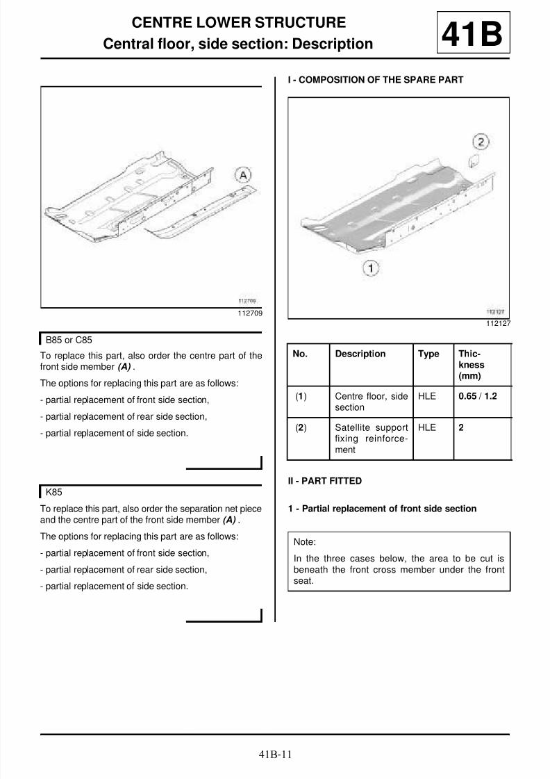
8/21/2019 Panelwork 2009+
http://slidepdf.com/reader/full/panelwork-2009 98/31341B-11
CENTRE LOWER STRUCTURE
Central floor, side section: Description 41B
To replace this part, also order the centre part of thefront side member (A) .
The options for replacing this part are as follows:
- partial replacement of front side section,
- partial replacement of rear side section,
- partial replacement of side section.
To replace this part, also order the separation net pieceand the centre part of the front side member (A) .
The options for replacing this part are as follows:
- partial replacement of front side section,
- partial replacement of rear side section,
- partial replacement of side section.
I - COMPOSITION OF THE SPARE PART
II - PART FITTED
1 - Partial replacement of front side section
112709
B85 or C85
K85
112127
No. Description Type Thic-kness(mm)
(1) Centre floor, side
section
HLE 0.65 / 1.2
(2) Satellite supportfixing reinforce-ment
HLE 2
Note:In the three cases below, the area to be cut isbeneath the front cross member under the frontseat.

8/21/2019 Panelwork 2009+
http://slidepdf.com/reader/full/panelwork-2009 99/31341B-12
CENTRE LOWER STRUCTURE
Central floor, side section: Description 41B
2 - Partial replacement of rear side section
3 - Partial replacement of side section
4 - Detailed view of separation net piece
replacement
112649
112650
112648
WARNING
If the mating faces of the parts to be welded are notaccessible, make EGW plug welds to replace theoriginal resistance welds (see MR 400).
K85
126699
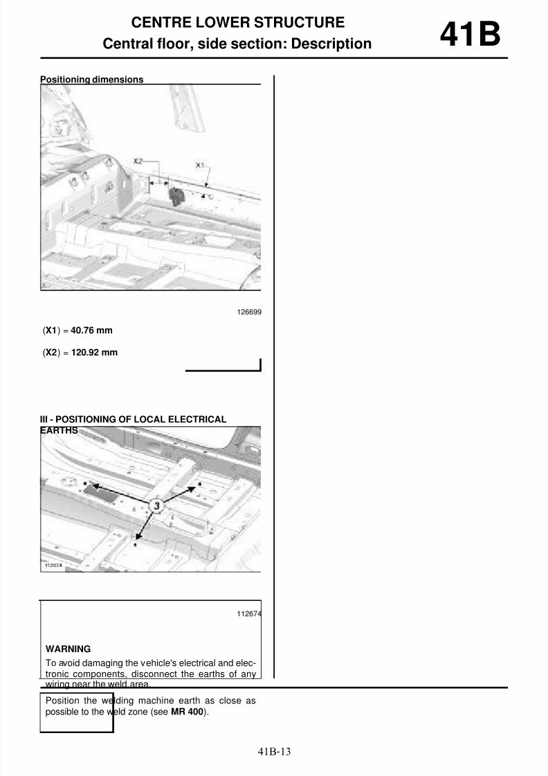
8/21/2019 Panelwork 2009+
http://slidepdf.com/reader/full/panelwork-2009 100/31341B-13
CENTRE LOWER STRUCTURE
Central floor, side section: Description 41BPositioning dimensions
(X1) = 40.76 mm
(X2) = 120.92 mm
III - POSITIONING OF LOCAL ELECTRICALEARTHS
126699
112674
WARNING
To avoid damaging the vehicle's electrical and elec-tronic components, disconnect the earths of anywiring near the weld area.
Position the welding machine earth as close aspossible to the weld zone (see MR 400).

8/21/2019 Panelwork 2009+
http://slidepdf.com/reader/full/panelwork-2009 101/31341C-1
SIDE LOWER STRUCTURE
Sill panel: Description
B85 or K85
41C
To replace this part, also order the expanding insertscorresponding to each of the following cases.
The options for replacing this part are as follows:
- partial replacement of the front end section, order theexterior A-pillar insert (see 40A , General informa-tion, Hollow body parts inserts: List and location
of components, page 40A-16) ,
- partial replacement under door:
- partial replacement of the front section, order the in-sert (A) and the exterior A-pillar insert (see 40A, Ge-neral information, Hollow body parts inserts: Listand location of components, page 40A-16) ,
- partial replacement of the rear end section, order thewheel arch insert (see 40A, General information,Hollow body parts inserts: List and location ofcomponents, page 40A-16) ,
- partial replacement of the rear section, order the in-sert (A) and the wheel arch insert (see 40A, Generalinformation, Hollow body parts inserts: List andlocation of components, page 40A-16) ,
- complete replacement, order the insert (A) , the exte-rior A-pillar insert and the wheel arch insert (see 40A,General information, Hollow body parts inserts:
List and location of components, page 40A-16) .
I - COMPOSITION OF THE SPARE PART
II - PART FITTED
Partial replacement of the front end section
113238
112131
No. Description Type Thic-kness(mm)
(1) Sill panel HLE 0.65/0.95
(2) Jacking point HLE 2
112639

8/21/2019 Panelwork 2009+
http://slidepdf.com/reader/full/panelwork-2009 102/31341C-2
SIDE LOWER STRUCTURE
Sill panel: Description
B85 or K85
41C
Replacement under door
Front section replacement
Partial replacement of the rear end section
Partial replacement of the rear section
112638
112637
112636
112640

8/21/2019 Panelwork 2009+
http://slidepdf.com/reader/full/panelwork-2009 103/31341C-3
SIDE LOWER STRUCTURE
Sill panel: Description
B85 or K85
41C
Complete replacement
112634

8/21/2019 Panelwork 2009+
http://slidepdf.com/reader/full/panelwork-2009 104/31341C-4
SIDE LOWER STRUCTURE
Sill panel: Description
B85 or K85
41C
III - SPECIAL NOTES ON THE CUTS
Positioning of the cuts
- (X1) = 28 cm
- (X2) = 13 cm
- (X3) = 26 cm
Detailed view of cut A112635
WARNING
Respect the position of this cut which has beendetermined in accordance with the position of theinner stiffeners or acoustic inserts, in order to pre-vent damaging the parts (inner stiffener and/oracoustic insert).
113171

8/21/2019 Panelwork 2009+
http://slidepdf.com/reader/full/panelwork-2009 105/31341C-5
SIDE LOWER STRUCTURE
Sill panel: Description
B85 or K85
41C
Detailed view of cut B
Detailed view of cut C
Detailed view of cut D
Detailed view of cut E
113020
113019
113166
113167
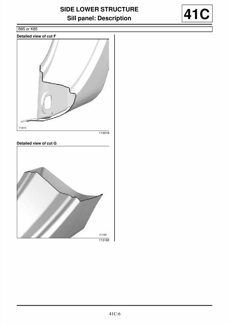
8/21/2019 Panelwork 2009+
http://slidepdf.com/reader/full/panelwork-2009 106/31341C-6
SIDE LOWER STRUCTURE
Sill panel: Description
B85 or K85
41C
Detailed view of cut F
Detailed view of cut G
113018
113168

8/21/2019 Panelwork 2009+
http://slidepdf.com/reader/full/panelwork-2009 107/31341C-7
SIDE LOWER STRUCTURE
Sill panel: Description
C85 or S85
41C
The options for replacing this part are as follows:
- partial replacement of the front end section: also or-
der the A-pillar insert (see 40A, General informa-
tion, Hollow body parts inserts: List and location
of components, page 40A-16) ,
- partial replacement under door:
- partial replacement of the rear end section,
- complete replacement: also order the A-pillar insert
(see 40A, General information, Hollow body parts
inserts: List and location of components, page
40A-16) .
I - COMPOSITION OF THE SPARE PART
II - PART FITTED
Partial replacement of the front end section
Replacement under door
113243
112132
No. Description Type Thic-kness
(mm) (1) Sill panel HLE 0.65/0.95
(2) Jacking point HLE 2
112639
112725

8/21/2019 Panelwork 2009+
http://slidepdf.com/reader/full/panelwork-2009 108/31341C-8
SIDE LOWER STRUCTURE
Sill panel: Description
C85 or S85
41C
Partial replacement of the rear end section
Complete replacement
112726
112727

8/21/2019 Panelwork 2009+
http://slidepdf.com/reader/full/panelwork-2009 109/31341C-9
SIDE LOWER STRUCTURE
Sill panel: Description
C85 or S85
41C
III - SPECIAL NOTES ON THE CUTS
Positioning of the cuts
- (X1) = 28 cm
- (X2) = 17 cm
Detailed view of cut H113047
WARNING
Respect the position of this cut which has beendetermined in accordance with the position of theinner stiffeners or acoustic inserts, in order to pre-vent damaging the parts (inner stiffener and/oracoustic insert).
113171

8/21/2019 Panelwork 2009+
http://slidepdf.com/reader/full/panelwork-2009 110/31341C-10
SIDE LOWER STRUCTURE
Sill panel: Description
C85 or S85
41C
Detailed view of cut I
Detailed view of cut J
Detailed view of cut K
Detailed view of cut K
113020
113169
113170
113172
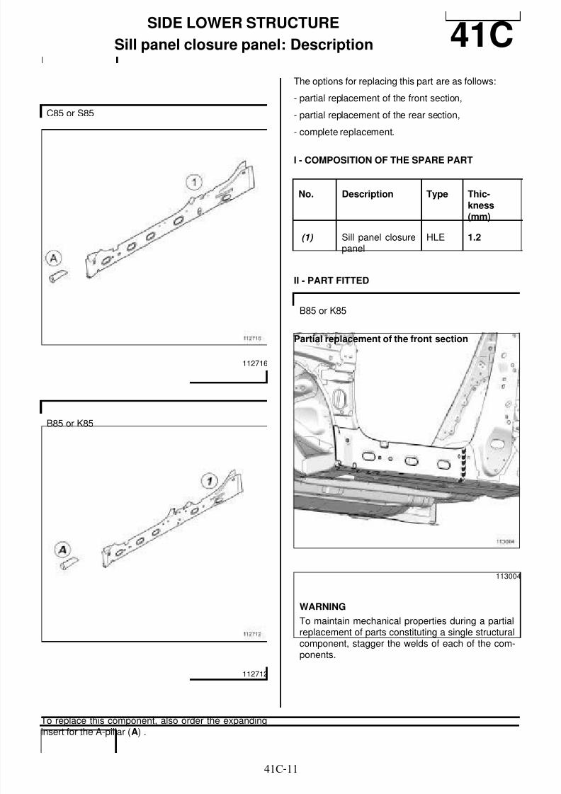
8/21/2019 Panelwork 2009+
http://slidepdf.com/reader/full/panelwork-2009 111/31341C-11
SIDE LOWER STRUCTURE
Sill panel closure panel: Description 41C
To replace this component, also order the expandinginsert for the A-pillar (A) .
The options for replacing this part are as follows:
- partial replacement of the front section,
- partial replacement of the rear section,
- complete replacement.
I - COMPOSITION OF THE SPARE PART
II - PART FITTED
Partial replacement of the front section
C85 or S85
112716
B85 or K85
112712
No. Description Type Thic-kness(mm)
(1) Sill panel closurepanel
HLE 1.2
B85 or K85
113004
WARNING
To maintain mechanical properties during a partialreplacement of parts constituting a single structuralcomponent, stagger the welds of each of the com-ponents.

8/21/2019 Panelwork 2009+
http://slidepdf.com/reader/full/panelwork-2009 112/31341C-12
SIDE LOWER STRUCTURE
Sill panel closure panel: Description 41CPartial replacement of the rear section
III - SPECIAL NOTES ON THE CUTS
113001
WARNING
If the mating faces of the parts to be welded are notaccessible, make EGW plug welds to replace the
original resistance welds (see MR 400).
B85 or K85
Note:
The position of the cuts given in the procedure canbe modified according to the severity of impact.
113000

8/21/2019 Panelwork 2009+
http://slidepdf.com/reader/full/panelwork-2009 113/31341C-13
SIDE LOWER STRUCTURE
Sill panel closure panel: Description 41CDetailed view of cut A
Detailed view of cut B
IV - PART FITTED
Partial replacement of the front section
Partial replacement of the rear section
113173
113175
C85 or S85
113003
WARNINGTo maintain mechanical properties during a partialreplacement of parts constituting a single structuralcomponent, stagger the welds of each of the com-ponents.
113002

8/21/2019 Panelwork 2009+
http://slidepdf.com/reader/full/panelwork-2009 114/31341C-14
SIDE LOWER STRUCTURE
Sill panel closure panel: Description 41CV - SPECIAL NOTES ON THE CUTS
WARNING
If the mating faces of the parts to be welded are notaccessible, make EGW plug welds to replace the
original resistance welds (see MR 400).
C85 or S85
Note:
The position of the cuts given in the procedure canbe modified according to the severity of impact.
112999
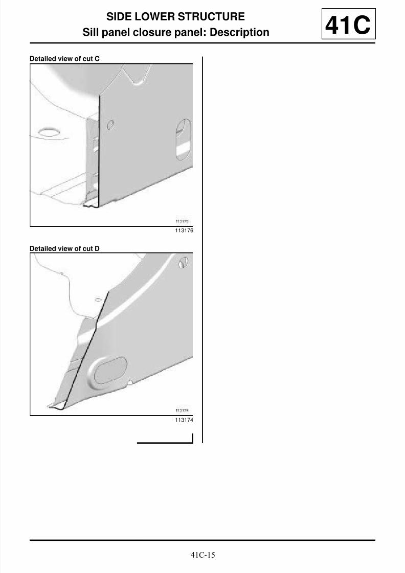
8/21/2019 Panelwork 2009+
http://slidepdf.com/reader/full/panelwork-2009 115/31341C-15
SIDE LOWER STRUCTURE
Sill panel closure panel: Description 41CDetailed view of cut C
Detailed view of cut D
113176
113174

8/21/2019 Panelwork 2009+
http://slidepdf.com/reader/full/panelwork-2009 116/31341C-16
SIDE LOWER STRUCTURE
Sill panel reinforcement: General description 41C
I - DESIGN OF THE STRUCTURAL COMPONENT
Replacement of the sill panel reinforcement is linked toreplacement of the inner sill panel.
II - AREA TO BE CUT FOR PARTIALREPLACEMENT
Note:
The information contained in the following descri-bes the general repair procedure for all vehicleshaving the same design for this part.
Before reading this general information, check thatthere are no special notes associated with this vehi-cle. These special notes will be specified if applica-ble in other parts of this subsection dealing with thepart.
Note:
For a detailed description of a particular connec-
tion, see MR 400.
113262
113005
113006

8/21/2019 Panelwork 2009+
http://slidepdf.com/reader/full/panelwork-2009 117/31341C-17
SIDE LOWER STRUCTURE
Sill panel reinforcement: Description 41C
The options for replacing this part are as follows:
- partial replacement of the front section,
- partial replacement of the rear section,
- complete replacement.
Description and thickness of the component
I - PART FITTED
Partial replacement of the front section
Partial replacement of the rear section
113263
No. Description Type Thic-kness(mm)
(1) Sill panel rein-forcement
HLE 1.5
113005
WARNING
For the partial replacement of parts constituting asingle structural component, it is essential to stag-
ger the welds of each of the components.
113006

8/21/2019 Panelwork 2009+
http://slidepdf.com/reader/full/panelwork-2009 118/31341C-18
SIDE LOWER STRUCTURE
Sill panel reinforcement: Description 41C
II - PART FITTED
WARNING
If the spot welds cannot be made as they were ori-ginally using an electrical spot welding machine,
they should be replaced with plug welds after holeshave been drilled in the first panel.
C85
WARNING
For the partial replacement of parts constituting a
single structural component, it is essential to stag-ger the welds of each of the components.
113007
WARNING
If the spot welds cannot be made as they were ori-ginally using an electrical spot welding machine,they should be replaced with plug welds after holeshave been drilled in the first panel.
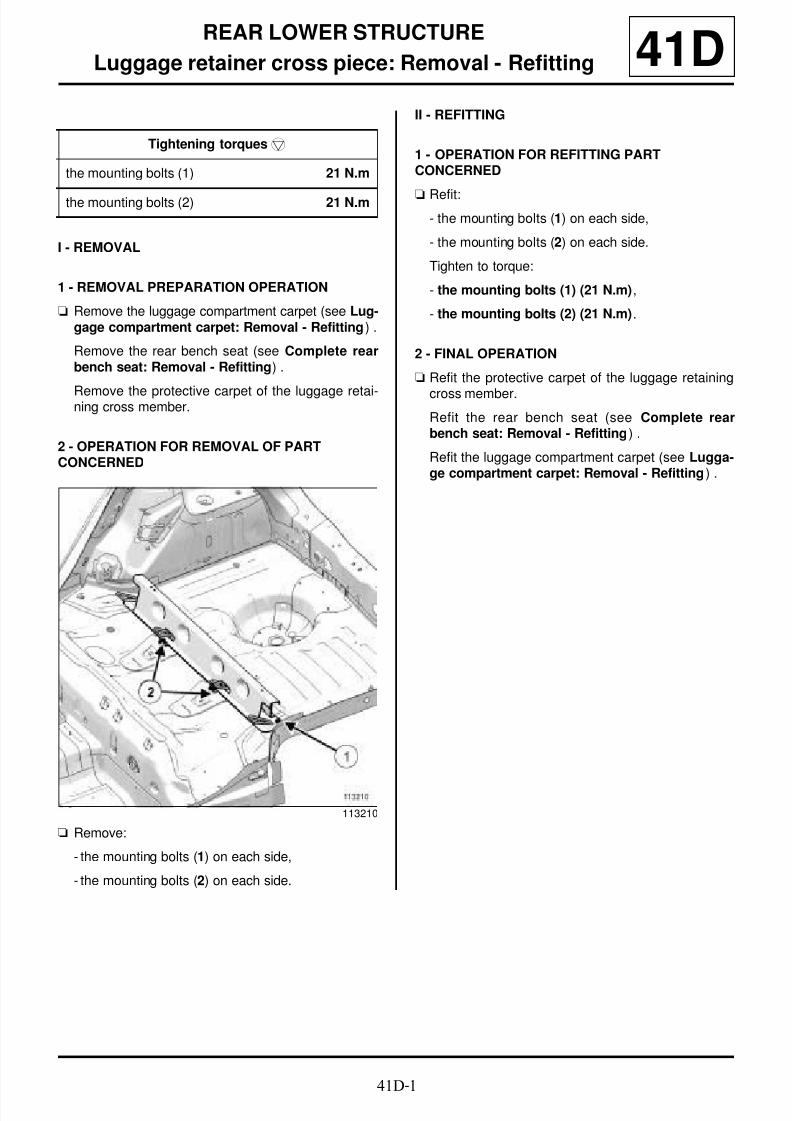
8/21/2019 Panelwork 2009+
http://slidepdf.com/reader/full/panelwork-2009 119/31341D-1
REAR LOWER STRUCTURE
Luggage retainer cross piece: Removal - Refitting 41D
I - REMOVAL
1 - REMOVAL PREPARATION OPERATION
a Remove the luggage compartment carpet (see Lug-gage compartment carpet: Removal - Refitting) .
Remove the rear bench seat (see Complete rearbench seat: Removal - Refitting) .
Remove the protective carpet of the luggage retai-ning cross member.
2 - OPERATION FOR REMOVAL OF PARTCONCERNED
a Remove:
- the mounting bolts (1) on each side,
- the mounting bolts (2) on each side.
II - REFITTING
1 - OPERATION FOR REFITTING PARTCONCERNED
a Refit:
- the mounting bolts (1) on each side,
- the mounting bolts (2) on each side.
Tighten to torque:
- the mounting bolts (1) (21 N.m),
- the mounting bolts (2) (21 N.m).
2 - FINAL OPERATION
a Refit the protective carpet of the luggage retaining
cross member.
Refit the rear bench seat (see Complete rearbench seat: Removal - Refitting) .
Refit the luggage compartment carpet (see Lugga-ge compartment carpet: Removal - Refitting) .
Tightening torquesm
the mounting bolts (1) 21 N.m
the mounting bolts (2) 21 N.m
113210

8/21/2019 Panelwork 2009+
http://slidepdf.com/reader/full/panelwork-2009 120/31341D-2
REAR LOWER STRUCTURE
Rear floor, front section: General description 41D
I - DESIGN OF THE STRUCTURAL COMPONENT
This is a basic part; its only function is that of rear floorfront section.
II - AREA TO BE CUT FOR PARTIALREPLACEMENT
Cut 1:
This line marks the area in which it is possible to makea partial replacement.
III - ASSEMBLY INSTRUCTIONS FOR A PARTIALREPLACEMENT
Only the connections which are specific to the partialreplacement by cutting are indicated.
WARNING
The information contained in the following descri-bes the general repair procedure for all vehicles
having the same design for this part.
Before reading the following general information,make sure that there are no special notes associa-ted with the vehicle. These special notes are speci-fied if necessary in other parts of the sub-sectiondealing with the component.
Note:
For a detailed description of a particular connec-
tion, see MR 400.
112594
113099
113098

8/21/2019 Panelwork 2009+
http://slidepdf.com/reader/full/panelwork-2009 121/31341D-3
REAR LOWER STRUCTURE
Rear floor, front section: General description 41DIf there are other issues regarding access to mating fa-ces, the various replacement options are described inthe basic instructions for structural bodywork repair(see MR 400).
Line (2) on the diagram shows a joint made by jogglingconnected with plug welds at regular intervals.
WARNING
If the mating faces of the parts to be welded are notaccessible, make EGW plug welds to replace the
original resistance welds (see MR 400).
110650

8/21/2019 Panelwork 2009+
http://slidepdf.com/reader/full/panelwork-2009 122/31341D-4
REAR LOWER STRUCTURE
Rear floor, front section: Description 41D
The options for replacing this part are as follows:
- partial replacement of the rear section,
- complete replacement.
I - COMPOSITION OF THE SPARE PART
112594
112133
B85 or C85 or S85
No. Description Type Thic-kness(mm)
(1) Floor cross mem-ber
0.65
(2) Front section ofrear floor
0.65
(3) Floor side reinfor-cement
HLE 1.5
(4) Central reinforce-ment of seat HLE 1.5
K85
No. Description Type Thic-kness(mm)
(1) Emergency sparewheel arch rearreinforcement
HLE 1,7
(2) Rear floor rearsection
Mildsteel
0.65
(3) Rear section ofrear floor exten-sion
HLE 0.65
(4) Emergency sparewheel mountingreinforcement
HLE 1.5

8/21/2019 Panelwork 2009+
http://slidepdf.com/reader/full/panelwork-2009 123/31341D-5
REAR LOWER STRUCTURE
Rear floor, front section: Description 41DII - PART FITTED
Partial replacement of the rear section
WARNING
To maintain mechanical properties during a partialreplacement of parts constituting a single structuralcomponent, stagger the welds of each of the com-ponents.
WARNING
Respect the position of this cut which has beendetermined in accordance with the position of theinner stiffeners or acoustic inserts, in order to pre-vent damaging the parts (inner stiffener and/oracoustic insert).
113099
Note:
Carry out partial replacement by superposition ofpanels, and make two welds.
113098
WARNING
If the mating faces of the parts to be welded are notaccessible, make EGW plug welds to replace theoriginal resistance welds (see MR 400).

8/21/2019 Panelwork 2009+
http://slidepdf.com/reader/full/panelwork-2009 124/31341D-6
REAR LOWER STRUCTURE
Rear floor rear section: General description 41D
I - DESIGN OF THE STRUCTURAL COMPONENT
The distinctive feature of this part is that it combinesthe functions of the rear section of the rear floor and theemergency spare wheel mounting bracket.
Partial replacement is not possible for this part.
II - ASSEMBLY INSTRUCTIONS FOR A PARTIALREPLACEMENT
Only the connections which are specific to the partialreplacement by cutting are indicated.
If there are other issues regarding access to mating fa-ces, the various replacement options are described inthe basic instructions for structural bodywork repair(see MR 400).
Note:
The information contained in the following descri-bes the general repair procedure for all vehicleshaving the same design for this part.
Before reading the following general information,make sure that there are no special notes associa-ted with the vehicle. These special notes are speci-fied if necessary in other parts of the sub-sectiondealing with the component.
Note:
For a detailed description of a particular connec-
tion, see MR 400.
110618
WARNING
If the mating faces of the parts to be welded are notaccessible, make EGW plug welds to replace the
original resistance welds (see MR 400).

8/21/2019 Panelwork 2009+
http://slidepdf.com/reader/full/panelwork-2009 125/31341D-7
REAR LOWER STRUCTURE
Rear floor rear section: Description 41D
There is only one way of replacing this part:
- complete replacement.
I - COMPOSITION OF THE SPARE PART
112593
B85 or C85 or S85, and EQUIPMENT LEVEL E3
LEISURE or EQT LEVEL EA1 or EQT LEVEL EA2or EQT LEVEL EA3 or EQT LEVEL EA4 or EQTLEVEL EA5 or EQT LEVEL EAG
112134
No. Description Type Thickness(mm)
(1) Rear section offloor - 0.65
(2) Emergency sparewheel side moun-ting reinforcement
HLE 1.5
(3) Emergency sparewheel mountingreinforcement
HLE 1.5
(4) Rear wheel archreinforcement
HLE 1.5
C85, and EQUIPMENT LEVEL EAC or EQT LEVELSPORT
116933

8/21/2019 Panelwork 2009+
http://slidepdf.com/reader/full/panelwork-2009 126/31341D-8
REAR LOWER STRUCTURE
Rear floor rear section: Description 41D
II - PART IN POSITION
Complete replacement
No. Description Type Thickness(mm)
(5) Rear floor rearsection - 0.65
(6) Rear floor reinfor-cement
- 1.5
K85
126701
No. Description Type Thic-kness(mm)
(7) Rear floor rearsection
Mildsteel
0.65
(8) Emergency sparewheel mountingreinforcement
HLE 1.5
(9) Emergency sparewheel arch rearreinforcement
HLE 1.7
(10) Rear floor exten-
sion
HLE 0.65
B85 or C85 or S85, and EQUIPMENT LEVEL E3LEISURE or EQT LEVEL EA1 or EQT LEVEL EA2or EQT LEVEL EA3 or EQT LEVEL EA4 or EQTLEVEL EA5 or EQT LEVEL EAG
113100

8/21/2019 Panelwork 2009+
http://slidepdf.com/reader/full/panelwork-2009 127/31341D-9
REAR LOWER STRUCTURE
Rear floor rear section: Description 41D
P = pitch
D = distance covered
C85, and EQUIPMENT LEVEL EAC or EQT LEVELSPORT
116932
K85
126702
WARNING
If the spot welds cannot be made as they were ori-ginally using an electrical spot welding machine,
these should be replaced with anchoring beading.
WARNING
If the mating faces of the parts to be welded are notaccessible, make EGW plug welds to replace theoriginal resistance welds (see MR 400).

8/21/2019 Panelwork 2009+
http://slidepdf.com/reader/full/panelwork-2009 128/31341D-10
REAR LOWER STRUCTURE
Rear side member assembly: Description 41D
There is only one way of replacing this part:
- complete replacement.
I - COMPOSITION OF THE SPARE PART
126792
IMPORTANT
Use a repair bench to ensure the positioning of the
points and the geometry of the axle assemblies.
B85 or C85 or S85
112135
No. Description Type Thic-kness(mm)
(1) Towing ring reinfor-cement
HLE 2
(2) Central reinforce-ment
HLE 1.5
(3) Rear axle mountinginterior reinforce-ment
HLE 2.8
(4) Rear side member HLE 1.5
(5) Si l l connectioncomponent 1.2
(6) Rear axle mountingexterior reinforce-ment
HLE 2.8
(7) Sill reinforcement VHEL 1.5
(8) Suspension springsupport
HLE 2
K85
126703

8/21/2019 Panelwork 2009+
http://slidepdf.com/reader/full/panelwork-2009 129/31341D-11
REAR LOWER STRUCTURE
Rear side member assembly: Description 41DII - PART IN POSITION
Complete replacementNo. Description Type Thic-
kness(mm)
(9) Sill reinforcement VHEL 1.5
(10) Upper sill con-nection compo-nent
Mildsteel
1.2
(11) Rear axle moun-ting exterior rein-forcement
HLE 2.8
(12) Rear central sidemember reinfor-
cement
HLE 1.5
(13) Rear axle moun-ting interior rein-forcement
HLE 2.8
(14) Rear side mem-ber
HLE 1.5
(15) Lower sill con-nection compo-nent
HLE 1.5
(16) Suspensionspring support
HLE 2
(17) Side memberextension
HLE 2
B85 or C85 or S85
113101
113102
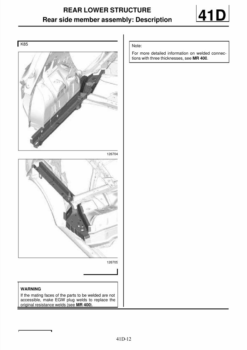
8/21/2019 Panelwork 2009+
http://slidepdf.com/reader/full/panelwork-2009 130/31341D-12
REAR LOWER STRUCTURE
Rear side member assembly: Description 41D
K85
126704
126705
WARNING
If the mating faces of the parts to be welded are notaccessible, make EGW plug welds to replace the
original resistance welds (see MR 400).
Note:
For more detailed information on welded connec-tions with three thicknesses, see MR 400.
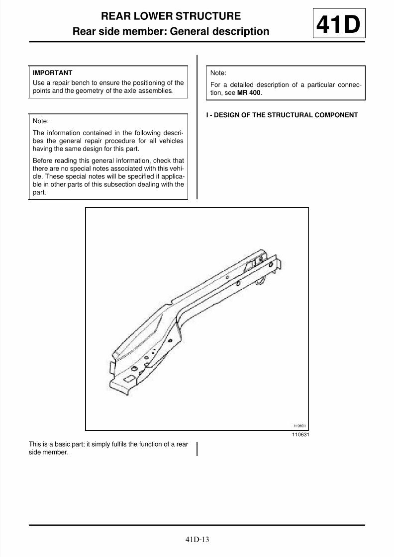
8/21/2019 Panelwork 2009+
http://slidepdf.com/reader/full/panelwork-2009 131/31341D-13
REAR LOWER STRUCTURE
Rear side member: General description 41D
I - DESIGN OF THE STRUCTURAL COMPONENT
This is a basic part; it simply fulfils the function of a rearside member.
IMPORTANT
Use a repair bench to ensure the positioning of thepoints and the geometry of the axle assemblies.
Note:
The information contained in the following descri-bes the general repair procedure for all vehicleshaving the same design for this part.
Before reading this general information, check thatthere are no special notes associated with this vehi-cle. These special notes will be specified if applica-ble in other parts of this subsection dealing with the
part.
Note:
For a detailed description of a particular connec-tion, see MR 400.
110631

8/21/2019 Panelwork 2009+
http://slidepdf.com/reader/full/panelwork-2009 132/31341D-14
REAR LOWER STRUCTURE
Rear side member: General description 41DII - AREA TO BE CUT FOR PARTIALREPLACEMENT
Cut 1:
This line marks the area in which it is possible to makea partial replacement.
III - ASSEMBLY INSTRUCTIONS FOR A PARTIALREPLACEMENT
Only the connections which are specific to the partial
replacement by cutting are indicated.
If there are other issues regarding access to mating fa-ces, the various replacement options are described inthe basic instructions for structural bodywork repair(see MR 400).
110632
WARNING
If the mating faces of the parts to be welded are notaccessible, make EGW plug welds to replace theoriginal resistance welds (see MR 400).

8/21/2019 Panelwork 2009+
http://slidepdf.com/reader/full/panelwork-2009 133/31341D-15
REAR LOWER STRUCTURE
Rear side member: General description 41D
The line (2) on the drawing shows a butt weld made bycontinuous GMAW welding.
110633

8/21/2019 Panelwork 2009+
http://slidepdf.com/reader/full/panelwork-2009 134/31341D-16
REAR LOWER STRUCTURE
Rear side member, rear section: Description 41D
There is only one way of replacing this part:
- Partial replacement of the rear section.
I - COMPOSITION OF THE SPARE PART
II - PART IN POSITION
Partial replacement of the rear section
X1 = 70 mm
112598
IMPORTANT
The straightening bench must be used.
112136
No. Description Type Thic-kness(mm)
(1) Rear side member HLE 1.5
(2) Towing ring reinfor-cement
HLE 2
(3) Threaded bushing
(4) Towing ring ∅ 8
WARNING
The correct position of this cut must be observed,as it is determined according to the mounting pointsfor the mechanical components.
WARNING
If the spot welds cannot be made as they were ori-ginally using an electrical spot welding machine,they should be replaced with plug welds after holeshave been drilled in the first panel.
113103

8/21/2019 Panelwork 2009+
http://slidepdf.com/reader/full/panelwork-2009 135/31341D-17
REAR LOWER STRUCTURE
Rear floor front cross member stiffener: General description 41D
Workshop Repair Manual 400, 40A, General infor-mation).
I - STRUCTURAL COMPONENT DESIGN
This is a basic part; it simply fulfils the function of a rearfloor front cross member stiffener.
II - AREA TO BE CUT FOR PARTIALREPLACEMENT
This line (1) marks the place in which it is possible tomake a partial replacement.
This operation allows you to access the inside of thehollow section of the structural element to straighten it.
III - ASSEMBLY INSTRUCTIONS FOR A PARTIALREPLACEMENT
Only the connecting pieces relevant to partial replace-ment by cutting are shown.
WARNING
The information contained in the following descri-bes the general repair procedure for all vehicles
having the same design for this part.
Before reading this general information, check thatthere are no special features associated with thisvehicle. These special features will be specified ifapplicable in other parts of this sub-section dealingwith the part.
Note:
For detailed information on a specific connection,
(see
112595
113104
113104
8/21/2019 Panelwork 2009+
http://slidepdf.com/reader/full/panelwork-2009 136/31341D-18
REAR LOWER STRUCTURE
Rear floor front cross member stiffener: General description 41DLine (2) of the drawing shows a butt weld by conti-nuous MAG welding.
If there are other issues regarding access to mating fa-ces, the various replacement options are described inthe basic instructions for structural bodywork repair(see MR 400, 40A, General information).
WARNING
If the spot welds cannot be made as they were ori-ginally using an electrical spot welding machine,these should be replaced with plug welds afterholes have been drilled in the first panel.
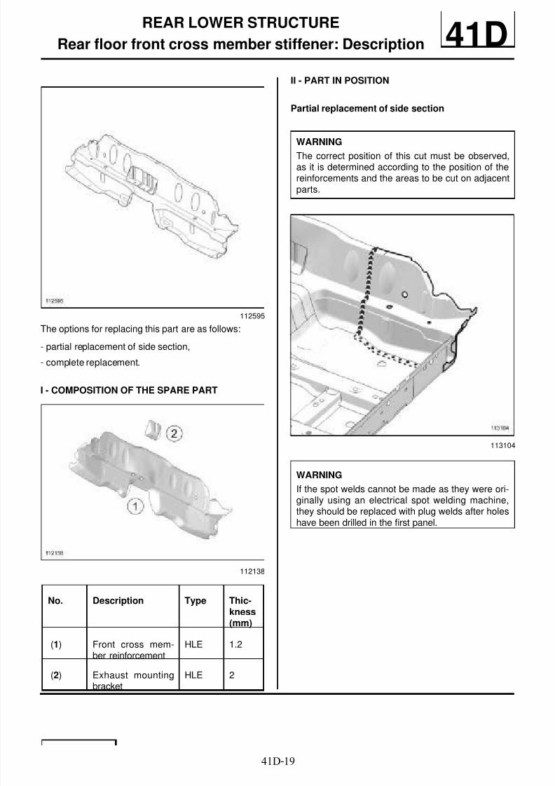
8/21/2019 Panelwork 2009+
http://slidepdf.com/reader/full/panelwork-2009 137/31341D-19
REAR LOWER STRUCTURE
Rear floor front cross member stiffener: Description 41D
The options for replacing this part are as follows:
- partial replacement of side section,
- complete replacement.
I - COMPOSITION OF THE SPARE PART
II - PART IN POSITION
Partial replacement of side section
112595
112138
No. Description Type Thic-kness(mm)
(1) Front cross mem-ber reinforcement
HLE 1.2
(2) Exhaust mounting
bracket
HLE 2
WARNING
The correct position of this cut must be observed,as it is determined according to the position of thereinforcements and the areas to be cut on adjacentparts.
113104
WARNING
If the spot welds cannot be made as they were ori-ginally using an electrical spot welding machine,they should be replaced with plug welds after holeshave been drilled in the first panel.
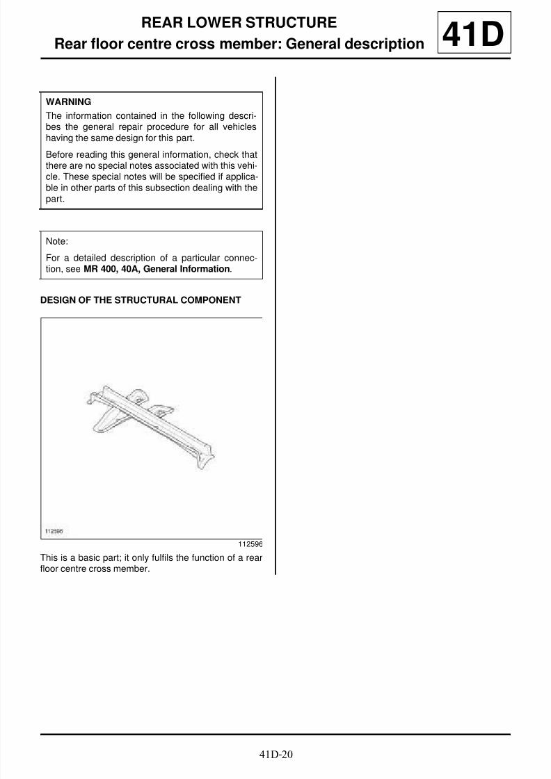
8/21/2019 Panelwork 2009+
http://slidepdf.com/reader/full/panelwork-2009 138/31341D-20
REAR LOWER STRUCTURE
Rear floor centre cross member: General description 41D
DESIGN OF THE STRUCTURAL COMPONENT
This is a basic part; it only fulfils the function of a rearfloor centre cross member.
WARNING
The information contained in the following descri-bes the general repair procedure for all vehicles
having the same design for this part.
Before reading this general information, check thatthere are no special notes associated with this vehi-cle. These special notes will be specified if applica-ble in other parts of this subsection dealing with thepart.
Note:
For a detailed description of a particular connec-
tion, see MR 400, 40A, General Information.
112596

8/21/2019 Panelwork 2009+
http://slidepdf.com/reader/full/panelwork-2009 139/31341D-21
REAR LOWER STRUCTURE
Rear floor centre cross member: Description 41D
There is only one way of replacing this part:
- complete replacement.
I - COMPOSITION OF THE SPARE PART
112596
B85 or C85 or S85
112139
No. Description Type Thic-kness(mm)
(1) Rear centre crossmember
HLE 1.4
(2) Fuel tank protec-tion component
HLE 1
(3) Fuel tank moun-ting reinforcement
HLE 1
K85
126712

8/21/2019 Panelwork 2009+
http://slidepdf.com/reader/full/panelwork-2009 140/31341D-22
REAR LOWER STRUCTURE
Rear floor centre cross member: Description 41D
II - PART IN POSITION
Complete replacement
No. Description Type Thic-kness(mm)
(4) Seat belt ancho-rage point reinfor-cement
HLE 1.2
(5) Side member HLE 1.2
(6) Rear cent recross member
HLE 1.2
(7) Tank mountingreinforcement
HLE 1
(8) Fuel tank protec-tion component HLE 1
113105
WARNING
If the mating faces of the parts to be welded are notaccessible, make EGW plug welds to replace theoriginal resistance welds (see MR 400).
Note:
For more detailed information on welded connec-tions with three thicknesses, see MR 400.

8/21/2019 Panelwork 2009+
http://slidepdf.com/reader/full/panelwork-2009 141/31341D-23
REAR LOWER STRUCTURE
Rear floor rear cross member: Description
K85
41D
There is only one way of replacing this part:
- complete replacement.
I - COMPOSITION OF THE SPARE PART
II - PART IN POSITION
126783
No. Description Type Thic-kness(mm)
(1) Rear floor rearcross member
HLE 1.2
126713
WARNING
If the mating faces of the parts to be welded are notaccessible, make EGW plug welds to replace theoriginal resistance welds (see MR 400).
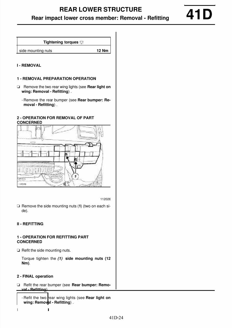
8/21/2019 Panelwork 2009+
http://slidepdf.com/reader/full/panelwork-2009 142/31341D-24
REAR LOWER STRUCTURE
Rear impact lower cross member: Removal - Refitting 41D
I - REMOVAL
1 - REMOVAL PREPARATION OPERATION
a Remove the two rear wing lights (see Rear light onwing: Removal - Refitting) .
- Remove the rear bumper (see Rear bumper: Re-moval - Refitting) .
2 - OPERATION FOR REMOVAL OF PARTCONCERNED
a Remove the side mounting nuts (1) (two on each si-de).
II - REFITTING
1 - OPERATION FOR REFITTING PARTCONCERNED
a Refit the side mounting nuts.
Torque tighten the (1) side mounting nuts (12Nm).
2 - FINAL operation
a Refit the rear bumper (see Rear bumper: Remo-val - Refitting) .
- Refit the two rear wing lights (see Rear light onwing: Removal - Refitting) .
Tightening torquesm
side mounting nuts 12 Nm
112026
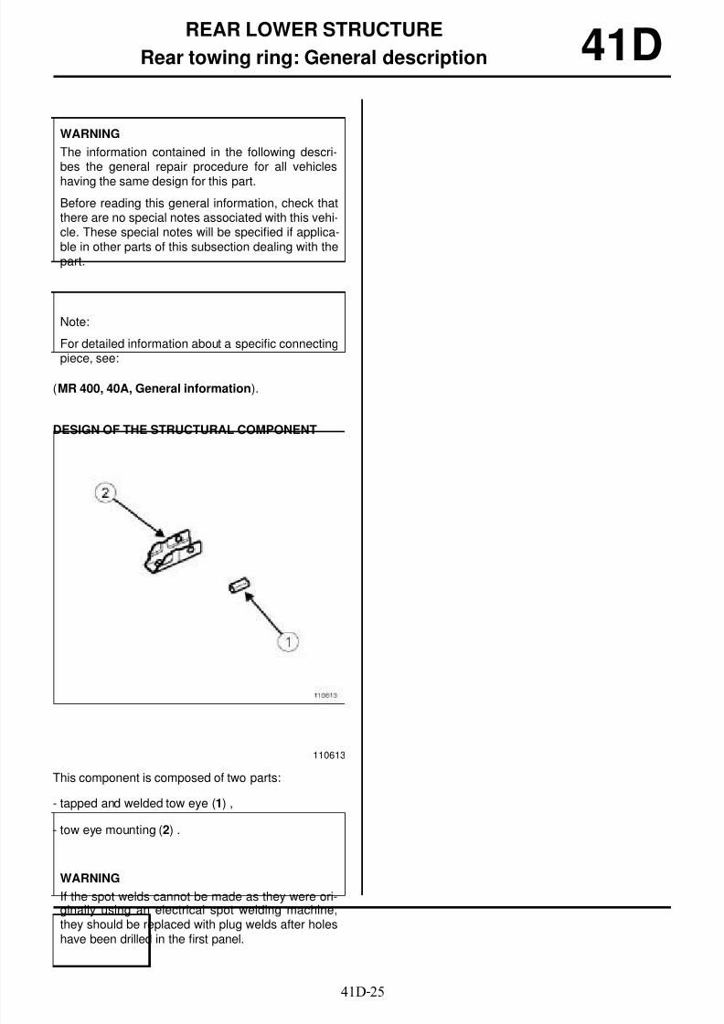
8/21/2019 Panelwork 2009+
http://slidepdf.com/reader/full/panelwork-2009 143/31341D-25
REAR LOWER STRUCTURE
Rear towing ring: General description 41D
(MR 400, 40A, General information).
DESIGN OF THE STRUCTURAL COMPONENT
This component is composed of two parts:
- tapped and welded tow eye (1) ,
- tow eye mounting (2) .
WARNING
The information contained in the following descri-bes the general repair procedure for all vehicles
having the same design for this part.
Before reading this general information, check thatthere are no special notes associated with this vehi-cle. These special notes will be specified if applica-ble in other parts of this subsection dealing with thepart.
Note:
For detailed information about a specific connecting
piece, see:
110613
WARNING
If the spot welds cannot be made as they were ori-ginally using an electrical spot welding machine,they should be replaced with plug welds after holeshave been drilled in the first panel.
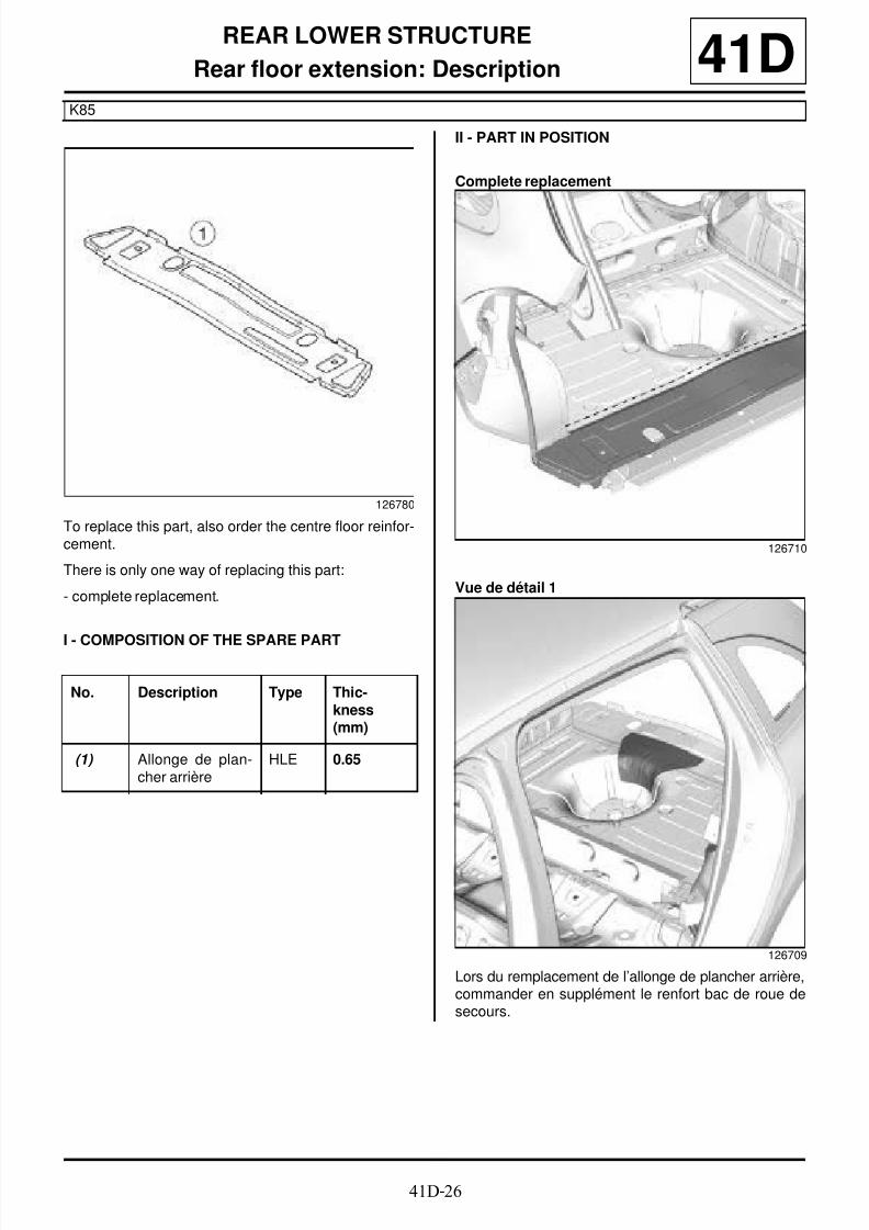
8/21/2019 Panelwork 2009+
http://slidepdf.com/reader/full/panelwork-2009 144/31341D-26
REAR LOWER STRUCTURE
Rear floor extension: Description
K85
41D
To replace this part, also order the centre floor reinfor-cement.
There is only one way of replacing this part:
- complete replacement.
I - COMPOSITION OF THE SPARE PART
II - PART IN POSITION
Complete replacement
Vue de détail 1
Lors du remplacement de l’allonge de plancher arrière,commander en supplément le renfort bac de roue desecours.
126780
No. Description Type Thic-kness(mm)
(1) Allonge de plan-cher arrière
HLE 0.65
126710
126709

8/21/2019 Panelwork 2009+
http://slidepdf.com/reader/full/panelwork-2009 145/31341D-27
REAR LOWER STRUCTURE
Rear floor extension: Description
K85
41D
Vue de détail 2
P = pas
D = distance de recouvrement
126711
WARNING
If the mating faces of the parts to be welded are not
accessible, make EGW plug welds to replace theoriginal resistance welds (see MR 400).

8/21/2019 Panelwork 2009+
http://slidepdf.com/reader/full/panelwork-2009 146/31341D-28
REAR LOWER STRUCTURE
Rear side member extension: Description
K85
41D
There is only one way of replacing this part:
- complete replacement.
I - COMPOSITION OF THE SPARE PART
II - PART IN POSITION
Vue de dessus
126782
126708
No. Description Type Thic-kness
(mm) (1) Allonge de longe-
ron arrière droitMildsteel
2
(2) Rear towing ring
(3) Douille anneaud’arrimage
Mildsteel
126706

8/21/2019 Panelwork 2009+
http://slidepdf.com/reader/full/panelwork-2009 147/31341D-29
REAR LOWER STRUCTURE
Rear side member extension: Description
K85
41D
Vue de dessous
126707
WARNING
If the mating faces of the parts to be welded are notaccessible, make EGW plug welds to replace theoriginal resistance welds (see MR 400).

8/21/2019 Panelwork 2009+
http://slidepdf.com/reader/full/panelwork-2009 148/31342A-1
FRONT UPPER STRUCTURE
Front wing: General description 42A
I - DESIGN OF THE STRUCTURAL COMPONENT
This type of front wing has the following characteristics:
- plastic wing (NORYL),
- wing bolted to its upper mounting bracket.
II - REMOVAL - REFITTING
To remove or replace the front wing, remove:
- the front wheel arch liner,
- the front bumper,
- the headlight,
- the windscreen lower trim piece.
III - ADJUSTMENT
Two main areas of adjustment may be identified:
- the adjustment of the rear area,
- the adjustment of the front area
1 - Adjustment of the rear area:
Note:
The information contained in the following descri-bes the general repair procedure for all vehicleshaving the same design for this part.
Before reading the following general information,make sure that there are no special notes associa-ted with the vehicle. These special notes are speci-fied if necessary in other parts of the sub-sectiondealing with the component.
112606
Note:
In all cases of removal of a component without itsreplacement with a new one, mark the position ofthe mountings before removing the mountings toavoid adjustments during refitting.
Note:
The front wing is the penultimate removable compo-nent to be fitted to the vehicle body in the factory.
For final adjustment, correctly position all the othercomponents including the bumper and the headli-ghts for them to be correctly positioned.
112042

8/21/2019 Panelwork 2009+
http://slidepdf.com/reader/full/panelwork-2009 149/31342A-2
FRONT UPPER STRUCTURE
Front wing: General description 42A
Adjust the flush fitting and alignment with the front door
using mountings (4) and (5) .
2 - Adjustment of the front area:
Adjust the alignment of the front wing using mountings
(14) and (15) .
112041
112039
112040

8/21/2019 Panelwork 2009+
http://slidepdf.com/reader/full/panelwork-2009 150/31342A-3
FRONT UPPER STRUCTURE
Front wing: Removal - Refitting 42A
The front wing is a structural bodywork componentmade of thermoplastic, and can be removed.
REMOVAL
I - REMOVAL PREPARATION OPERATION
a Remove:
- the front wheel arch liner (see Front wheel archliner: Removal - Refitting) (MR 393, 55A, Exteriorprotection),
- the front bumper (see Front bumper: Removal -Refitting) (MR 393, 55A, Exterior protection),
- the headlight (see Halogen headlight: Removal -Refitting) (MR 392, 80B, Headlights),
- the scuttle panel grille (see Scuttle panel grille:Removal - Refitting) (MR 393, 56A, Exterior ac-cessories),
- the windscreen trim piece (see Windscreen trim:Removal - Refitting) (MR 393, 54A, Windows).
II - OPERATION FOR REMOVAL OF PARTCONCERNED
a Remove:
- the front wing interior soundproofing material,
- the front wing mounting bolts,
- the mounting nut (10) ,
- the plastic nuts (A) ,
- the front wing.
Tightening torquesm
bolt (1) 6.5 Nm
bolt (2) 6.5 Nm
bolt (3) 6.5 Nm
bolt (4) 6.5 Nm
bolt (5) 6.5 Nm
bolt (6) 4.5 Nm
bolt (7) 4.5 Nm
bolt (8) 4.5 Nm
bolt (9) 6.5 Nm
nut (10) 4.5 Nm
114284

8/21/2019 Panelwork 2009+
http://slidepdf.com/reader/full/panelwork-2009 151/31342A-4
FRONT UPPER STRUCTURE
Front wing: Removal - Refitting 42AREFITTING
I - REFITTING PREPARATIONS OPERATION
a In the event of a front wing replacement operation,provide the Parts Department with the details of thetyre dimensions written on the front wing (11) .
II - REFITTING OPERATION FOR PARTCONCERNED
a Refit:
- the front wing,
- the plastic nuts (A) ,
a Refit:
- the front wing mounting bolts,
- the nut (10) ,
- the headlight (see Halogen headlight: Removal -Refitting) (MR 392, 80B, Headlights).
a Adjust the shut lines of the front wing. (see 42A,Front upper structure, Front wing: Adjusting,page 42A-6)
a Torque tighten:
- the bolt (1) (6.5 Nm),
- the bolt (2) (6.5 Nm),
- the bolt (3) (6.5 Nm),
- the bolt (4) (6.5 Nm),
- the bolt (5) (6.5 Nm),
- the bolt (6) (4.5 Nm),
- the bolt (7) (4.5 Nm),
- the bolt (8) (4.5 Nm),
- the bolt (9) (6.5 Nm),
- nut (10) (4.5 Nm).
a Refit the front wing interior soundproofing material.
III - FINAL OPERATION.
a Refit:
- the windscreen trim piece (see Windscreen trim:Removal - Refitting) (MR 393, 54A, Windows),
- the scuttle panel grille (see Scuttle panel grille:
Removal - Refitting) (MR 393, 56A, Exterior ac-cessories),
- the front bumper (see Front bumper: Removal -Refitting) (MR 393, 55A, Exterior protection),
112921
Note:
Tighten the plastic nuts (A) moderately so as notto damage them.
WARNINGThe tightening order must always be observed.

8/21/2019 Panelwork 2009+
http://slidepdf.com/reader/full/panelwork-2009 152/31342A-5
FRONT UPPER STRUCTURE
Front wing: Removal - Refitting 42A- the front wheel arch liner (see Front wheel archliner: Removal - Refitting) (MR 393, 55A, Exteriorprotection).
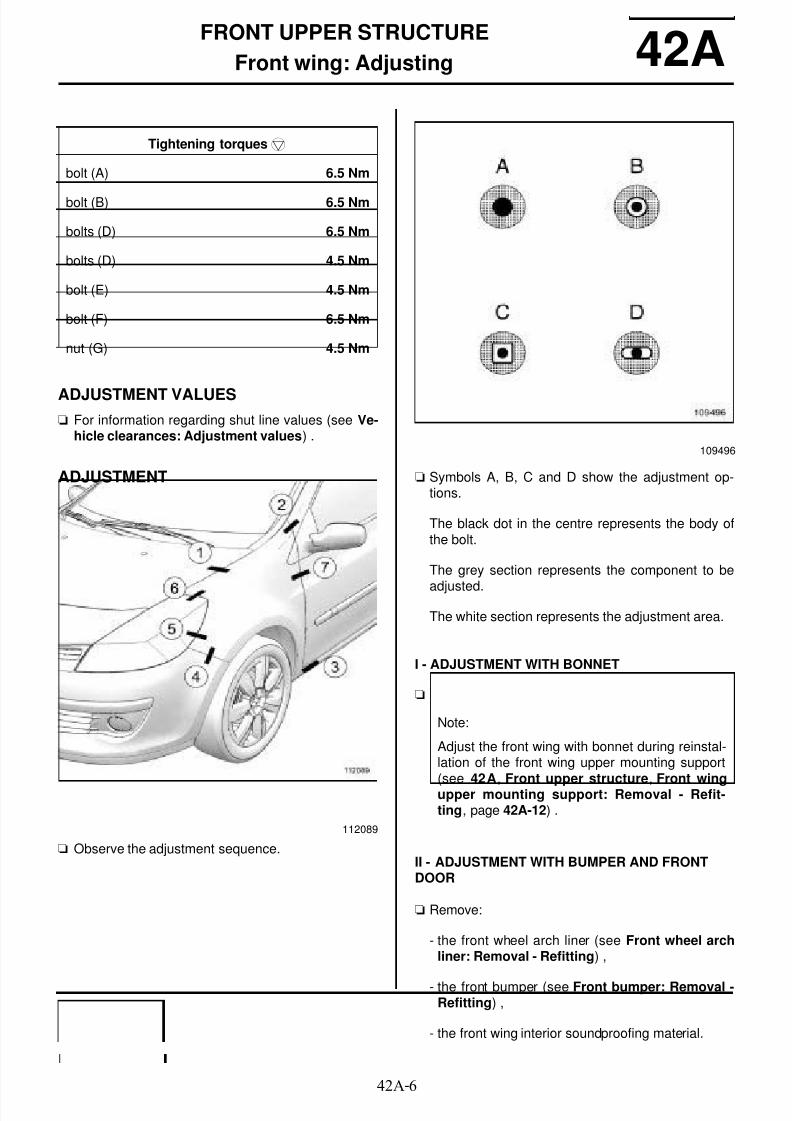
8/21/2019 Panelwork 2009+
http://slidepdf.com/reader/full/panelwork-2009 153/31342A-6
FRONT UPPER STRUCTURE
Front wing: Adjusting 42A
ADJUSTMENT VALUESa For information regarding shut line values (see Ve-
hicle clearances: Adjustment values) .
ADJUSTMENT
a Observe the adjustment sequence.
a Symbols A, B, C and D show the adjustment op-tions.
The black dot in the centre represents the body ofthe bolt.
The grey section represents the component to be
adjusted.
The white section represents the adjustment area.
I - ADJUSTMENT WITH BONNET
a
II - ADJUSTMENT WITH BUMPER AND FRONTDOOR
a Remove:
- the front wheel arch liner (see Front wheel archliner: Removal - Refitting) ,
- the front bumper (see Front bumper: Removal -Refitting) ,
- the front wing interior soundproofing material.
Tightening torquesm
bolt (A) 6.5 Nm
bolt (B) 6.5 Nm
bolts (D) 6.5 Nm
bolts (D) 4.5 Nm
bolt (E) 4.5 Nm
bolt (F) 6.5 Nm
nut (G) 4.5 Nm
112089
109496
Note:
Adjust the front wing with bonnet during reinstal-lation of the front wing upper mounting support
(see 42A, Front upper structure, Front wingupper mounting support: Removal - Refit-ting, page 42A-12) .

8/21/2019 Panelwork 2009+
http://slidepdf.com/reader/full/panelwork-2009 154/31342A-7
FRONT UPPER STRUCTURE
Front wing: Adjusting 42A
a Adjust the panel gaps with the front door.
a Torque tighten the bolt (A) (6.5 Nm).
a
a Torque tighten the bolt (B) (6.5 Nm).
a Adjust the panel gaps with the front door and the sill
panel.
a Torque tighten the bolts (D) (6.5 Nm).
a Adjust the shut lines with the front bumper and theheadlight.
a Torque tighten the bolts (D) (4.5 Nm).
112039
Note:
Tighten the plastic nuts moderately so as not to
damage them.
112042
112041
112040

8/21/2019 Panelwork 2009+
http://slidepdf.com/reader/full/panelwork-2009 155/31342A-8
FRONT UPPER STRUCTURE
Front wing: Adjusting 42A
a Torque tighten the bolt (E) (4.5 Nm).
a Adjust the panel gaps with the front door.
a Torque tighten:
-the bolt (F) (6.5 Nm),
- the nut (G) (4.5 Nm).
a Refit:
- the front wing interior soundproofing material,
- the front bumper (see Front bumper: Removal -Refitting) ,
- the front wheel arch liner (see Front wheel archliner: Removal - Refitting) .
112039
114468
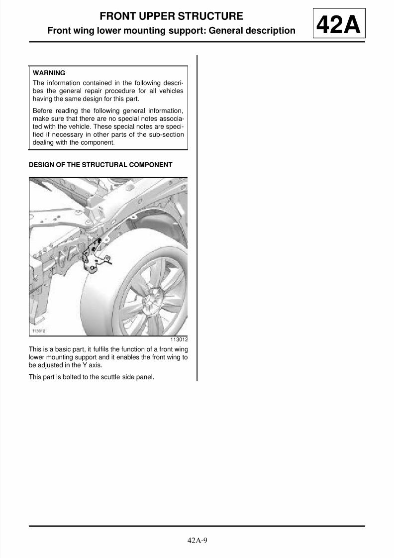
8/21/2019 Panelwork 2009+
http://slidepdf.com/reader/full/panelwork-2009 156/31342A-9
FRONT UPPER STRUCTURE
Front wing lower mounting support: General description 42A
DESIGN OF THE STRUCTURAL COMPONENT
This is a basic part, it fulfils the function of a front winglower mounting support and it enables the front wing tobe adjusted in the Y axis.
This part is bolted to the scuttle side panel.
WARNING
The information contained in the following descri-bes the general repair procedure for all vehicles
having the same design for this part.
Before reading the following general information,make sure that there are no special notes associa-ted with the vehicle. These special notes are speci-fied if necessary in other parts of the sub-sectiondealing with the component.
113012

8/21/2019 Panelwork 2009+
http://slidepdf.com/reader/full/panelwork-2009 157/31342A-10
FRONT UPPER STRUCTURE
Front wing lower mounting support: Removal - Refitting 42A
REMOVAL
I - REMOVAL PREPARATION OPERATION
a Remove:
- the front wheel arch liner (see Front wheel arch
liner: Removal - Refitting) (MR 393, 55A, Exteriorprotection),
- the front bumper (see Front bumper: Removal -
Refitting) (MR 393, 55A, Exterior protection),
- the headlight (see Halogen headlight: Removal -Refitting) (MR 392, 80B, Headlights),
- the front wing (see 42A , Front upper structure,
Front wing: Removal - Refitting, page 42A-3) .
II - OPERATION FOR REMOVAL OF PART
CONCERNED
a Remove:
- the nuts (1) ,
- the front wing lower mounting support.
REFITTING
I - REFITTING OPERATION FOR PARTCONCERNED
a Refit:
- the front wing lower mounting support,
- the nuts (1) .
a Torque tighten the nuts (1) (6.5 Nm).
II - FINAL OPERATION.
a Refit:
- the front wing (see 42A , Front upper structure,Front wing: Removal - Refitting, page 42A-3) ,
- the headlight (see Halogen headlight: Removal -Refitting) (MR 392, 80B, Headlights),
- the front bumper (see Front bumper: Removal -Refitting) (MR 393, 55A, Exterior protection),
- the front wheel arch liner (see Front wheel archliner: Removal - Refitting) (MR 393, 55A, Exteriorprotection).
Tightening torquesm
nuts (1) 6.5 Nm
113012
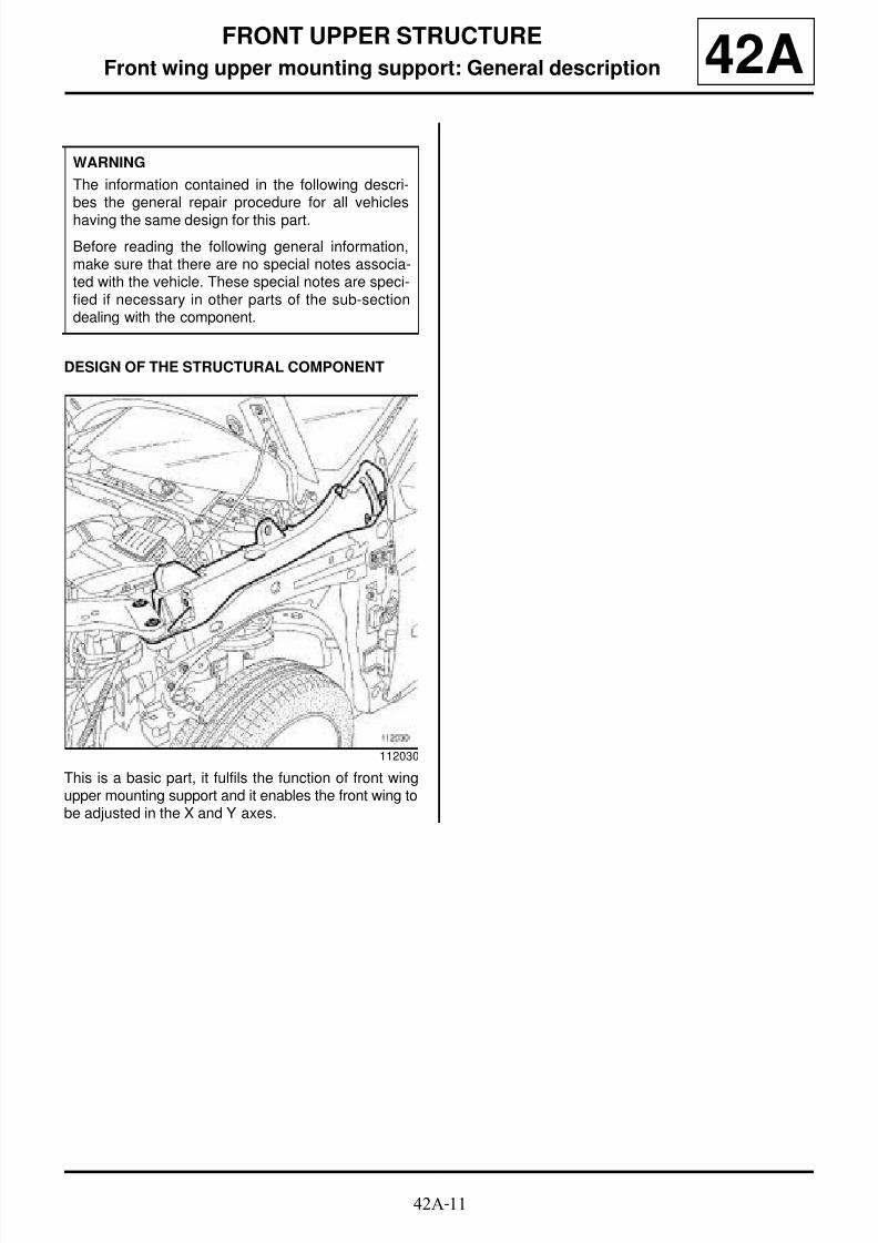
8/21/2019 Panelwork 2009+
http://slidepdf.com/reader/full/panelwork-2009 158/31342A-11
FRONT UPPER STRUCTURE
Front wing upper mounting support: General description 42A
DESIGN OF THE STRUCTURAL COMPONENT
This is a basic part, it fulfils the function of front wingupper mounting support and it enables the front wing tobe adjusted in the X and Y axes.
WARNING
The information contained in the following descri-bes the general repair procedure for all vehicles
having the same design for this part.
Before reading the following general information,make sure that there are no special notes associa-ted with the vehicle. These special notes are speci-fied if necessary in other parts of the sub-sectiondealing with the component.
112030

8/21/2019 Panelwork 2009+
http://slidepdf.com/reader/full/panelwork-2009 159/31342A-12
FRONT UPPER STRUCTURE
Front wing upper mounting support: Removal - Refitting 42A
REMOVAL
I - REMOVAL PREPARATION OPERATION
a Remove:
- the front wheel arch liner, front section (see Frontwheel arch liner: Removal - Refitting) ,
- (see Front bumper: Removal - Refitting) ,
- the front headlights (see Halogen headlight: Re-moval - Refitting) ,
- the front impact cross member (see 41A, Frontlower structure, Front impact cross member:Removal - Refitting, page 41A-2) .
- Remove the front wing (see 42A , Front upper
structure, Front wing: Removal - Refitting, page42A-3) .
II - OPERATION FOR REMOVAL OF PARTCONCERNED
a Remove:
- the bolts (1) ,
- the mounting nuts (2) from each side of the front
end panel (see 42A , Front upper structure,Front: Removal - Refitting, page 42A-16) .
a Partly remove the front end panel.
a Remove the indexing bolts (3) from the front end pa-nel.
Tightening torquesm
front panel indexing
bolts (3)
21 Nm
front wing upper moun-ting support bolts (1)
8 Nm
nuts (2) of the frontpanel mounting
21 Nm
112030
112065

8/21/2019 Panelwork 2009+
http://slidepdf.com/reader/full/panelwork-2009 160/31342A-13
FRONT UPPER STRUCTURE
Front wing upper mounting support: Removal - Refitting 42A
a Cut out the expanding insert (4) .
a Remove the front wing upper mounting support.
REFITTING
I - REFITTING PREPARATIONS OPERATION
a Fit the new expanding insert (5) on the upper moun-ting support of the front wing.
a Put a preformed mastic bead on the expanding in-sert.
II - REFITTING OPERATION FOR PARTCONCERNED
a Refit:
- the front wing upper mounting support,
- the bolts (1) ,
- the indexing bolts (3) .
a Position the front wing on its bracket.
a Adjust the shut lines of the front wing. (see 42A,Front upper structure, Front wing: Adjusting,page 42A-6)
a Torque tighten the front panel indexing bolts (3)(21 Nm).
aRemove the front wing.
a Torque tighten the front wing upper mountingsupport bolts (1) (8 Nm).
a Place an (6) MJP type seal at the expanding insert.
a Refit:
- the front end panel,
- the front panel mounting nuts (2) .
a Torque tighten the nuts (2) of the front panelmounting (21 Nm).
III - FINAL OPERATION.
a Refit:
- the front wing (see 42A , Front upper structure,Front wing: Removal - Refitting, page 42A-3) ,
112037
112486
112037
8/21/2019 Panelwork 2009+
http://slidepdf.com/reader/full/panelwork-2009 161/31342A-14
FRONT UPPER STRUCTURE
Front wing upper mounting support: Removal - Refitting 42A- the front impact cross member (see 41A, Frontlower structure, Front impact cross member:Removal - Refitting, page 41A-2) .
- the front headlights (see Halogen headlight: Re-moval - Refitting) ,
- the front bumper (see Front bumper: Removal -Refitting) ,
- the front wheel arch liner, front section (see Frontwheel arch liner: Removal - Refitting) .

8/21/2019 Panelwork 2009+
http://slidepdf.com/reader/full/panelwork-2009 162/31342A-15
FRONT UPPER STRUCTURE
Front: General description 42ADESIGN OF THE STRUCTURAL COMPONENT
A special feature of this part is that it is made out ofcomposite materials; it cannot be repaired and is bol-ted onto the vehicle.
This part is attached to the ends of the front side mem-ber and cannot be adjusted.
Note:
The information contained in the following descri-bes the general repair procedure for all vehicleshaving the same design for this part.
Before reading the following general information,make sure that there are no special notes associa-ted with the vehicle. These special notes are speci-fied if necessary in other parts of the sub-sectiondealing with the component.
110082

8/21/2019 Panelwork 2009+
http://slidepdf.com/reader/full/panelwork-2009 163/31342A-16
FRONT UPPER STRUCTURE
Front: Removal - Refitting 42A
REMOVAL
I - REMOVAL PREPARATION OPERATION
a Remove:
- the front wheel arch liner, front section (see Front
wheel arch liner: Removal - Refitting) ,
- the front bumper (see Front bumper: Removal -
Refitting) ,
- the front headlights (see Halogen headlight: Re-moval - Refitting) ,
- the front impact cross member (see 41A, Frontlower structure, Front impact cross member:Removal - Refitting, page 41A-2) .
a Remove:
- the bonnet catch (1) (see Bonnet latch: Removal- Refitting) ,
- the buzzer (2) (see Horn: Removal - Refitting) ,
- the clip (3) from the expansion bottle.
a Extract the expansion bottle from the front end pa-nel.
a Unclip the wiring harness from the front end panel.
a Remove (depending on equipment level):
- the air inlet nozzle (4) ,
- the intercooler cover (5) .
II - OPERATION FOR REMOVAL OF PARTCONCERNED
a
aRemove:
- the mounting nuts (7) ,
- the front end panel.
Tightening torquesm
nuts (7) of the front
panel mounting
21 Nm
112029
112043
Note:
To maintain the adjustment of the front endpanel, hold the indexing bolts (6) in position with
a 5 mm spanner while loosening the nuts.
112045

8/21/2019 Panelwork 2009+
http://slidepdf.com/reader/full/panelwork-2009 164/31342A-17
FRONT UPPER STRUCTURE
Front: Removal - Refitting 42AREFITTING
I - REFITTING OPERATION FOR PARTCONCERNED
a Refit:
- the front end panel,
- the mounting nuts (7) .
a Torque tighten the nuts (7) of the front panelmounting (21 Nm).
II - FINAL OPERATION.
a Refit (depending on equipment level):
- the intercooler cover (5) ,
- the air inlet nozzle (4) .
a Insert the expansion bottle into the front end panel.
a Refit:
- the clip (3) to the expansion bottle,
- the wiring harness,
- the buzzer (2) (see Horn: Removal - Refitting) ,
- the bonnet catch (1) (see Bonnet latch: Removal- Refitting) ,
- the front impact cross member (see 41A, Frontlower structure, Front impact cross member:Removal - Refitting, page 41A-2) ,
- the front headlights (see Halogen headlight: Re-moval - Refitting) ,
- the front bumper (see Front bumper: Removal -Refitting) ,
- the front wheel arch liner, front section (see Frontwheel arch liner: Removal - Refitting) .

8/21/2019 Panelwork 2009+
http://slidepdf.com/reader/full/panelwork-2009 165/31342A-18
FRONT UPPER STRUCTURE
Scuttle side panel: General description 42A
I - DESIGN OF THE STRUCTURAL COMPONENT
The special feature of this part it that it concurrentlyserves two functions:
- scuttle side panel,
- A-pillar lining.
II - AREA TO BE CUT FOR PARTIALREPLACEMENT
Cutting line (1) shows the area in which it is possible tomake a cut.
This operation allows you to access the inside of thehollow section.
III - ASSEMBLY METHOD FOR A PARTIALREPLACEMENT
Only the connections which are specific to the partialreplacement by cutting are indicated.
If there are other issues regarding access to mating fa-ces, the various replacement options are described inthe basic instructions for structural bodywork repair(see MR 400).
Note:
The information contained in the following descri-bes the general repair procedure for all vehicleshaving the same design for this part.
Before reading the following general information,make sure that there are no special notes associa-ted with the vehicle. These special notes are speci-fied if necessary in other parts of the sub-sectiondealing with the component.
Note:
For a detailed description of a particular connec-
tion, see MR 400.
112703
110638
WARNING
If the mating faces of the parts to be welded are notaccessible, make EGW plug welds to replace theoriginal resistance welds (see MR 400).

8/21/2019 Panelwork 2009+
http://slidepdf.com/reader/full/panelwork-2009 166/31342A-19
FRONT UPPER STRUCTURE
Scuttle side panel: General description 42A
Line (5) on the diagram shows partial replacement and
a weld by joggling with plug welds at regular intervals.
Depending on the exact position of the cut, EGW buttwelding may also be used.
110639

8/21/2019 Panelwork 2009+
http://slidepdf.com/reader/full/panelwork-2009 167/31342A-20
FRONT UPPER STRUCTURE
Cowl side panel: Description 42A
The options for replacing this part are as follows:
- partial replacement of front end section,
- partial replacement of the front section,
- complete replacement.
I - COMPOSITION OF THE SPARE PART
II - PART FITTED
1 - Partial replacement of the front end section
112703
112141
No. Description Type Thickness(mm)
(1) A-pillar lining HLE 0.85
(2) Dashboardcross membermounting unit
HLE 2
(3) A-pillar liningconnectingbracket
Veryhighyieldstrength
2
(4) A-pillar upperreinforcement
HLE 2
(5) A-pillar lowerreinforcement
Veryhighyieldstrength
2.5
(6) A-pillar liningreinforcement
HLE 1.5
112680

8/21/2019 Panelwork 2009+
http://slidepdf.com/reader/full/panelwork-2009 168/31342A-21
FRONT UPPER STRUCTURE
Cowl side panel: Description 42A2 - Partial replacement of the front section
This cut gives access to the front wheel arch.
3 - Complete replacement
III - POSITIONING OF LOCAL ELECTRICALEARTHS
112679
112678
IMPORTANT
For welded connections in three thicknesses, thespot welds on the part replaced should be made inthe same place as for the original joint to retain its
mechanical properties.
112244
IMPORTANT
To avoid damaging the vehicles electric and electro-nic components, the battery and the earths of anywiring harness near the weld area must be discon-
nected.
The earth of the welding machine must be placedas close as possible to the weld area.
WARNING
If the spot welds cannot be made as they were ori-ginally using an electric spot welding machine, theyshould be replaced with plug welds after holes havebeen drilled in the first panel.

8/21/2019 Panelwork 2009+
http://slidepdf.com/reader/full/panelwork-2009 169/31342A-22
FRONT UPPER STRUCTURE
Scuttle side panel upper reinforcement: General description 42A
DESIGN OF THE STRUCTURAL COMPONENT
This type of part secures the front panel and the frontwing upper mounting support.
Note:
The information contained in the following descri-bes the general repair procedure for all vehicleshaving the same design for this part.
Before reading the following general information,make sure that there are no special notes associa-ted with the vehicle. These special notes are speci-fied if necessary in other parts of the sub-sectiondealing with the component.
Note:
For a detailed description of a particular connec-
tion, see MR 400.
112704
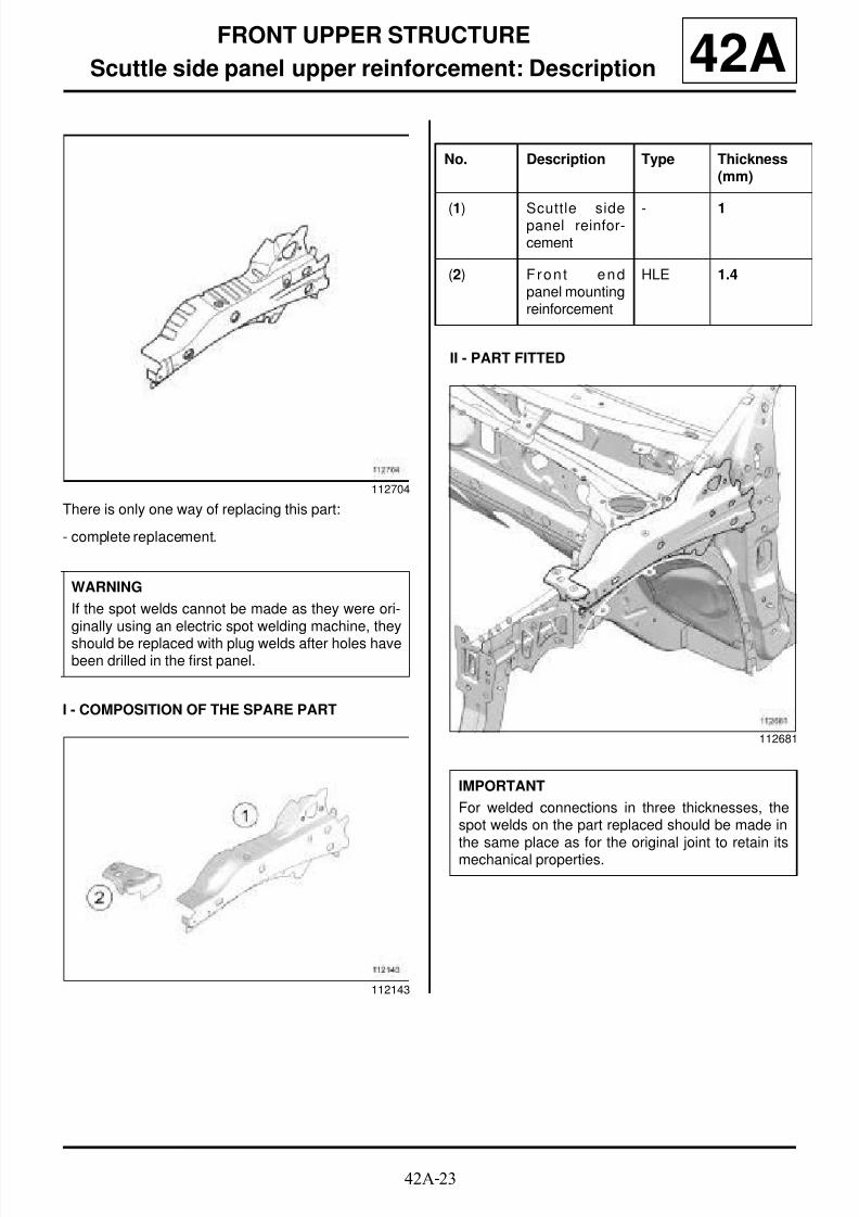
8/21/2019 Panelwork 2009+
http://slidepdf.com/reader/full/panelwork-2009 170/31342A-23
FRONT UPPER STRUCTURE
Scuttle side panel upper reinforcement: Description 42A
There is only one way of replacing this part:
- complete replacement.
I - COMPOSITION OF THE SPARE PART
II - PART FITTED
112704
WARNING
If the spot welds cannot be made as they were ori-ginally using an electric spot welding machine, they
should be replaced with plug welds after holes havebeen drilled in the first panel.
112143
No. Description Type Thickness(mm)
(1) Scuttle sidepanel reinfor-cement
- 1
(2) Fron t endpanel mountingreinforcement
HLE 1.4
112681
IMPORTANT
For welded connections in three thicknesses, thespot welds on the part replaced should be made inthe same place as for the original joint to retain itsmechanical properties.

8/21/2019 Panelwork 2009+
http://slidepdf.com/reader/full/panelwork-2009 171/31342A-24
FRONT UPPER STRUCTURE
Scuttle side panel upper reinforcement: Description 42AIII - POSITIONING OF LOCAL ELECTRICALEARTHS
112244
IMPORTANT
To avoid damaging the vehicles electric and electro-nic components, the earths of any wiring harnessnear the weld area must be disconnected.
The earth of the welding machine must be placedas close as possible to the weld area.

8/21/2019 Panelwork 2009+
http://slidepdf.com/reader/full/panelwork-2009 172/31342A-25
FRONT UPPER STRUCTURE
Front wheel arch: General description 42A
DESIGN OF THE STRUCTURAL COMPONENT
Left side
This is a basic part; it serves only as the front wheelarch.
Right-hand side
Two wheel arches are available, depending on the ve-
hicle engine type:
- with windscreen wiper mechanism mounting (1) ,
- with engine tie-rod attachment.
IMPORTANT
Use a repair bench to ensure the positioning of thepoints and the geometry of the axle assemblies.
Note:
The information contained in the following descri-bes the general repair procedure for all vehicleshaving the same design for this part.
Before reading the following general information,make sure that there are no special notes associa-ted with the vehicle. These special notes are speci-fied if necessary in other parts of the sub-section
dealing with the component.
Note:
For a detailed description of a particular connec-tion, see MR 400.
110635
110634

8/21/2019 Panelwork 2009+
http://slidepdf.com/reader/full/panelwork-2009 173/31342A-26
FRONT UPPER STRUCTURE
Front wheel arch: Description 42AFront left-hand wheel arch
Front right-hand wheel arch
There is only one way of replacing this part:
- complete replacement.
When replacing this part, also order:
- the heater bulkhead reinforcement (A) .
I - COMPOSITION OF THE SPARE PART
Front left-hand wheel arch
Front right-hand low torque wheel arch
112705
112706
IMPORTANT
The straightening bench must be used.
112145
No. Description Type Thickness(mm)
(1) Shock abso r-ber cup
HLE 2
(2) Cup heigh tadjuster
- 1.2
112144

8/21/2019 Panelwork 2009+
http://slidepdf.com/reader/full/panelwork-2009 174/31342A-27
FRONT UPPER STRUCTURE
Front wheel arch: Description 42A
Front right-hand high torque wheel arch
II - PART FITTED
III - POSITIONING OF LOCAL ELECTRICALEARTHS
No. Description Type Thickness(mm)
(3) Windscreenwiper moun-ting
HLE 2
113390
No. Description Type Thickness(mm)
(4) Engine tie-rodattachment
HLE 2
112678
WARNING
If the spot welds cannot be made as they were ori-ginally using an electric spot welding machine, theyshould be replaced with plug welds after holes havebeen drilled in the first panel.
112244
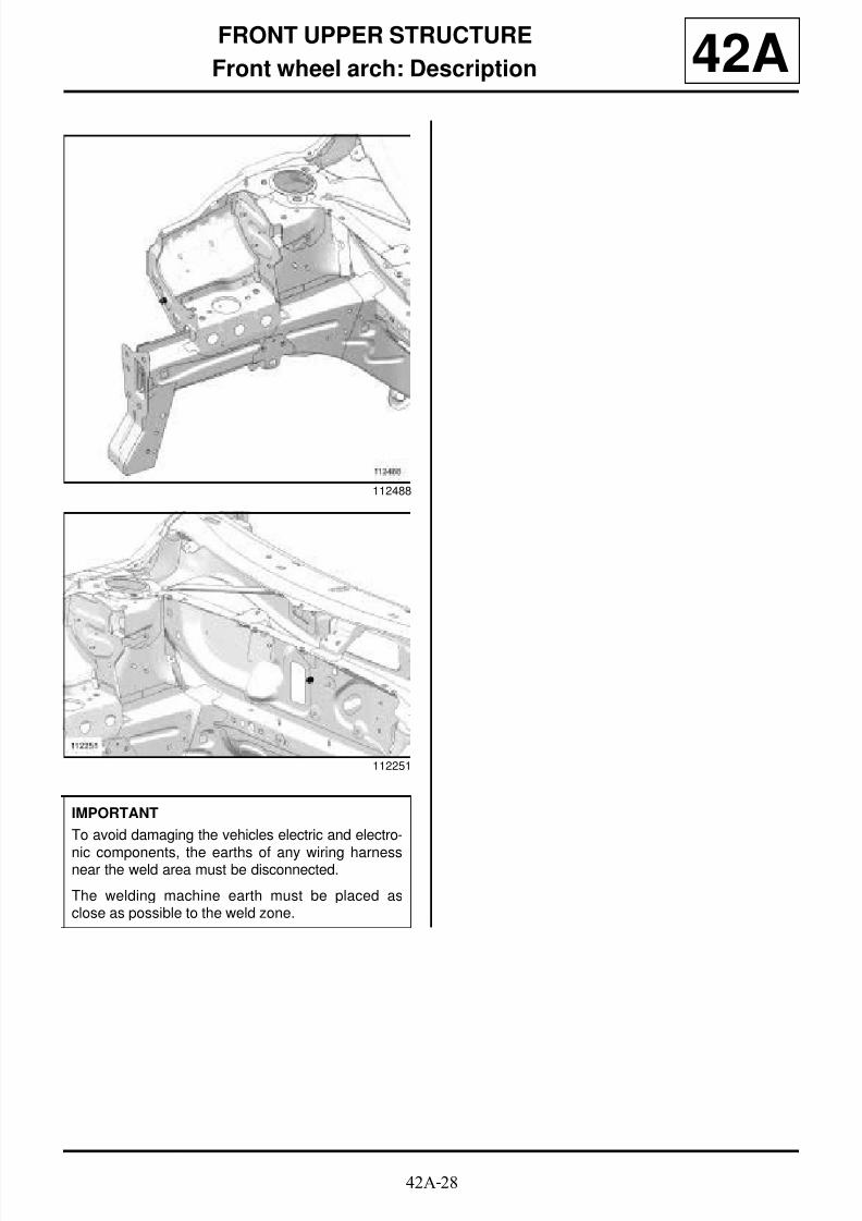
8/21/2019 Panelwork 2009+
http://slidepdf.com/reader/full/panelwork-2009 175/31342A-28
FRONT UPPER STRUCTURE
Front wheel arch: Description 42A
112488
112251
IMPORTANT
To avoid damaging the vehicles electric and electro-
nic components, the earths of any wiring harnessnear the weld area must be disconnected.
The welding machine earth must be placed asclose as possible to the weld zone.
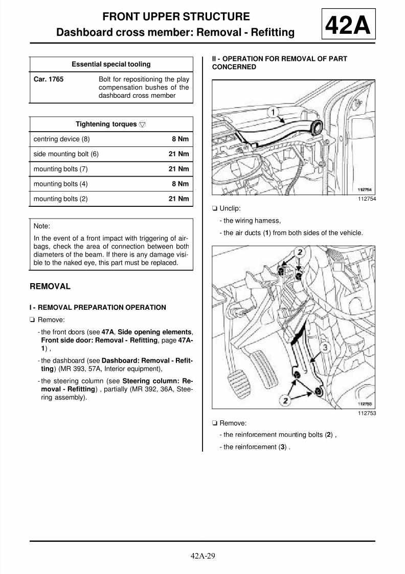
8/21/2019 Panelwork 2009+
http://slidepdf.com/reader/full/panelwork-2009 176/31342A-29
FRONT UPPER STRUCTURE
Dashboard cross member: Removal - Refitting 42A
REMOVAL
I - REMOVAL PREPARATION OPERATION
a Remove:
- the front doors (see 47A, Side opening elements,Front side door: Removal - Refitting, page 47A-1) ,
- the dashboard (see Dashboard: Removal - Refit-ting) (MR 393, 57A, Interior equipment),
- the steering column (see Steering column: Re-moval - Refitting) , partially (MR 392, 36A, Stee-ring assembly).
II - OPERATION FOR REMOVAL OF PARTCONCERNED
a Unclip:
- the wiring harness,
- the air ducts (1) from both sides of the vehicle.
a Remove:
- the reinforcement mounting bolts (2) ,
- the reinforcement (3) .
Essential special tooling
Car. 1765 Bolt for repositioning the playcompensation bushes of thedashboard cross member
Tightening torquesm
centring device (8) 8 Nm
side mounting bolt (6) 21 Nm
mounting bolts (7) 21 Nm
mounting bolts (4) 8 Nm
mounting bolts (2) 21 Nm
Note:
In the event of a front impact with triggering of air-bags, check the area of connection between bothdiameters of the beam. If there is any damage visi-ble to the naked eye, this part must be replaced.
112754
112753
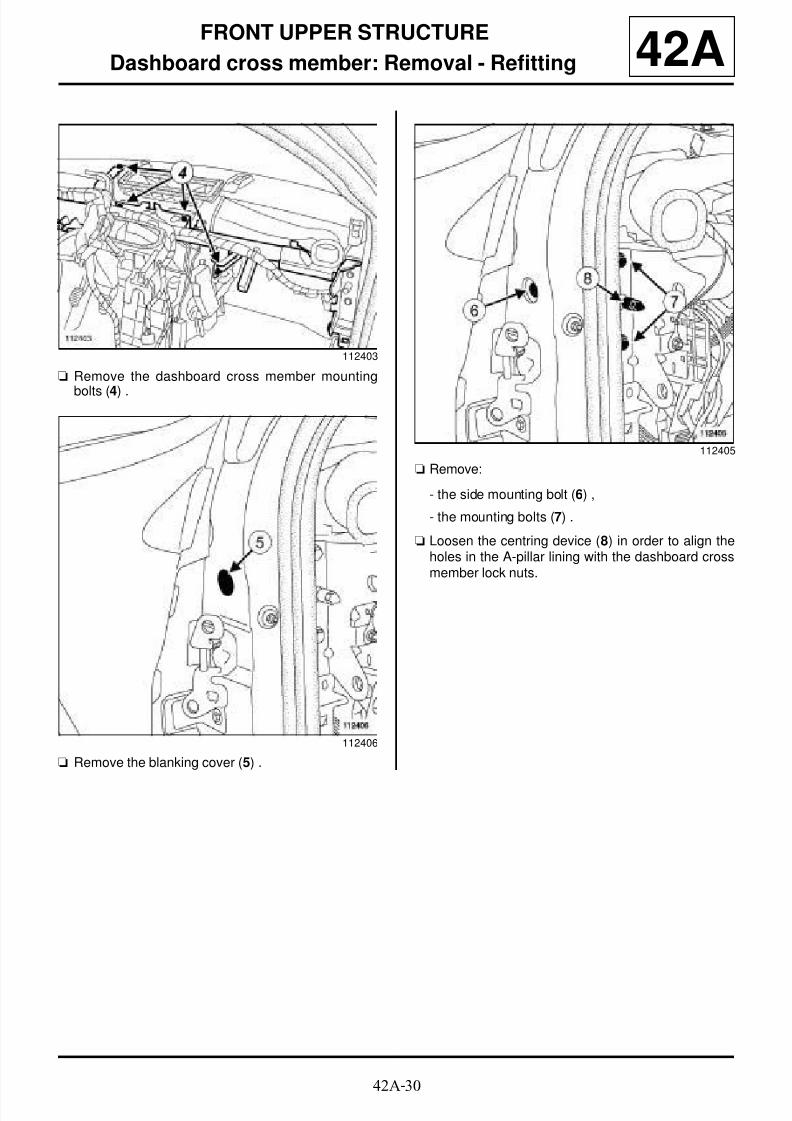
8/21/2019 Panelwork 2009+
http://slidepdf.com/reader/full/panelwork-2009 177/31342A-30
FRONT UPPER STRUCTURE
Dashboard cross member: Removal - Refitting 42A
a Remove the dashboard cross member mounting
bolts (4) .
a Remove the blanking cover (5) .
a Remove:
- the side mounting bolt (6) ,
- the mounting bolts (7) .
a Loosen the centring device (8) in order to align theholes in the A-pillar lining with the dashboard crossmember lock nuts.
112403
112406
112405

8/21/2019 Panelwork 2009+
http://slidepdf.com/reader/full/panelwork-2009 178/31342A-31
FRONT UPPER STRUCTURE
Dashboard cross member: Removal - Refitting 42A
a Fit the (Car. 1765) as far as the stop (9) .
a Screw the rod (10) onto the tool body (9) as far as
the stop.
a Firmly lock tool body in the same way as a lock nut
against the dashboard cross member nut while hol-
ding the hexagon bolt.
a Unscrew the whole tool as far as the stop and tigh-ten it gently (during this operation, the beam nut,
which has a left-hand thread, screws into the beam
and disengages it from the A-pillar).
a Hold the tool body (9) and unlock the rod (10) .
a Unscrew dashboard cross member rod to removethe tool.
a Remove:
- the mounting bolt (6) from the other side of the ve-
hicle,
- the dashboard cross member.
REFITTING
I - REFITTING OPERATION FOR PARTCONCERNED
a Fully tighten the locking nut (left-hand thread) in thebeam.
a Refit:
- the dashboard cross member,
- the mounting bolts (7) to position the cross mem-ber,
- the side mounting bolt (6) on the side where thelock nut has not been adjusted.
112407
112410
112408
Note:
To maintain the adjustment of the dashboardcross member and therefore make refittingeasier, only loosen the lock nut on one side.
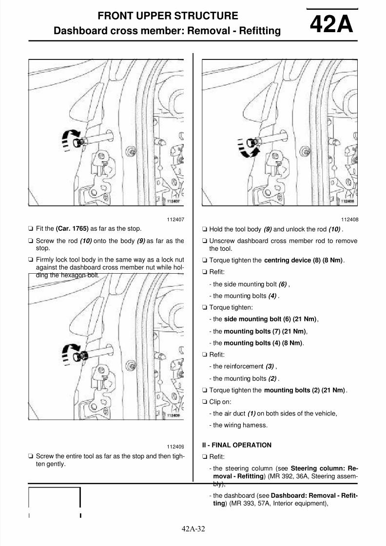
8/21/2019 Panelwork 2009+
http://slidepdf.com/reader/full/panelwork-2009 179/31342A-32
FRONT UPPER STRUCTURE
Dashboard cross member: Removal - Refitting 42A
a Fit the (Car. 1765) as far as the stop.
a Screw the rod (10) onto the body (9) as far as thestop.
a Firmly lock tool body in the same way as a lock nutagainst the dashboard cross member nut while hol-ding the hexagon bolt.
a Screw the entire tool as far as the stop and then tigh-ten gently.
a Hold the tool body (9) and unlock the rod (10) .
a Unscrew dashboard cross member rod to removethe tool.
a Torque tighten the centring device (8) (8 Nm).
a Refit:
- the side mounting bolt (6) ,- the mounting bolts (4) .
a Torque tighten:
- the side mounting bolt (6) (21 Nm),
- the mounting bolts (7) (21 Nm),
- the mounting bolts (4) (8 Nm).
a Refit:
- the reinforcement (3) ,
- the mounting bolts (2) .
a Torque tighten the mounting bolts (2) (21 Nm) .
a Clip on:
- the air duct (1) on both sides of the vehicle,
- the wiring harness.
II - FINAL OPERATION
a Refit:
- the steering column (see Steering column: Re-
moval - Refitting) (MR 392, 36A, Steering assem-bly),
- the dashboard (see Dashboard: Removal - Refit-ting) (MR 393, 57A, Interior equipment),
112407
112409
112408

8/21/2019 Panelwork 2009+
http://slidepdf.com/reader/full/panelwork-2009 180/31342A-33
FRONT UPPER STRUCTURE
Dashboard cross member: Removal - Refitting 42A- the front doors (see 47A, Side opening elements,Front side door: Removal - Refitting, page 47A-1) .
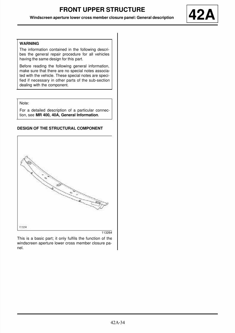
8/21/2019 Panelwork 2009+
http://slidepdf.com/reader/full/panelwork-2009 181/31342A-34
FRONT UPPER STRUCTUREWindscreen aperture lower cross member closure panel: General description 42A
DESIGN OF THE STRUCTURAL COMPONENT
This is a basic part; it only fulfils the function of thewindscreen aperture lower cross member closure pa-nel.
WARNING
The information contained in the following descri-bes the general repair procedure for all vehicles
having the same design for this part.
Before reading the following general information,make sure that there are no special notes associa-ted with the vehicle. These special notes are speci-fied if necessary in other parts of the sub-sectiondealing with the component.
Note:
For a detailed description of a particular connec-
tion, see MR 400, 40A, General Information.
113264

8/21/2019 Panelwork 2009+
http://slidepdf.com/reader/full/panelwork-2009 182/31342A-35
FRONT UPPER STRUCTURE
Windscreen aperture lower cross member closure panel: Description 42AThere is only one way of replacing this part:
- partial replacement.
I - COMPOSITION OF THE SPARE PART
II - PART IN POSITION
(X1) = 50 mm
Preserve the windscreen aperture lower cross memberwhen the cut is made.
III - POSITIONING OF LOCAL ELECTRICALEARTHS
113264
No. Description Type Thickness
(mm)
(1) Windscreenaperture lowercross mem-ber closurepanel
- 0.7
112862
WARNING
If the spot welds cannot be made as they were ori-ginally using an electric spot welding machine, theyshould be replaced with plug welds after holes havebeen drilled in the first panel.
112251

8/21/2019 Panelwork 2009+
http://slidepdf.com/reader/full/panelwork-2009 183/31342A-36
FRONT UPPER STRUCTURE
Windscreen aperture lower cross member closure panel: Description 42A
IMPORTANT
To avoid damaging the vehicles electric and electro-nic components, the earths of any wiring harness
near the weld area must be disconnected.
The welding machine earth must be placed asclose as possible to the weld zone.

8/21/2019 Panelwork 2009+
http://slidepdf.com/reader/full/panelwork-2009 184/31342A-37
FRONT UPPER STRUCTURE
Bulkhead lower cross member: General description 42A
DESIGN OF THE STRUCTURAL COMPONENT
This is a basic part; it simply fulfils the function of abulkhead cross member.
WARNING
Before reading the following general information,make sure that there are no special notes associa-
ted with the vehicle. These special notes are speci-fied if necessary in other parts of the sub-sectiondealing with the component.
Note:
For a detailed description of a particular connec-tion, see MR 400, 40A, General Information.
110640
WARNING
If the spot welds cannot be made as they were ori-ginally using an electrical spot welding machine,they should be replaced with plug welds after holeshave been drilled in the first panel.
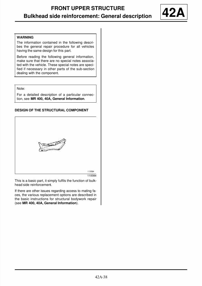
8/21/2019 Panelwork 2009+
http://slidepdf.com/reader/full/panelwork-2009 185/31342A-38
FRONT UPPER STRUCTURE
Bulkhead side reinforcement: General description 42A
DESIGN OF THE STRUCTURAL COMPONENT
This is a basic part, it simply fulfils the function of bulk-head side reinforcement.
If there are other issues regarding access to mating fa-ces, the various replacement options are described in
the basic instructions for structural bodywork repair(see MR 400, 40A, General Information).
WARNING
The information contained in the following descri-bes the general repair procedure for all vehicles
having the same design for this part.
Before reading the following general information,make sure that there are no special notes associa-ted with the vehicle. These special notes are speci-fied if necessary in other parts of the sub-sectiondealing with the component.
Note:
For a detailed description of a particular connec-
tion, see MR 400, 40A, General Information.
110084

8/21/2019 Panelwork 2009+
http://slidepdf.com/reader/full/panelwork-2009 186/31343A-1
SIDE UPPER STRUCTURE
A-pillar: General description
C85
43A
DESIGN OF THE STRUCTURAL COMPONENT
This is a basic part, its only function is that of an A-pillar.
WARNING
The information contained in the following descri-
bes the general repair procedure for all vehicleshaving the same design for this part.
Before reading the following general information,make sure that there are no special notes associa-ted with the vehicle. These special notes are speci-fied if necessary in other parts of the sub-sectiondealing with the component.
Note:For a detailed description of a particular connec-tion, see MR 400, 40A, General Information.
113240
WARNING
If the spot welds cannot be made as they were ori-
ginally using an electrical spot welding machine,they should be replaced with plug welds after holeshave been drilled in the first panel.

8/21/2019 Panelwork 2009+
http://slidepdf.com/reader/full/panelwork-2009 187/31343A-2
SIDE UPPER STRUCTURE
A-pillar: Description
C85 or S85
43A
I - COMPOSITION OF THE SPARE PART
II - PART IN POSITION
1 - Replacing the lower section of the A-pillar
113240
113234
No. Description Type Thickness(mm)
(1) Body side - 0.75
(2) Jacking point
bridge piece
Very
highyieldstrength
2
(3) Roo f ba rmounting pad
HLE 1.5
IMPORTANT
For welded connections in three thicknesses, thespot welds on the part replaced should be made inthe same place as for the original joint to retain itsmechanical properties.
WARNING
If the spot welds cannot be made as they were ori-ginally using an electrical spot welding machine,they should be replaced with plug welds after holeshave been drilled in the first panel.
WARNING
The position of this cut must be observed, and isdetermined according to the position of the internalreinforcements or acoustic inserts cut.
No. Description Type Thickness(mm)

8/21/2019 Panelwork 2009+
http://slidepdf.com/reader/full/panelwork-2009 188/31343A-3
SIDE UPPER STRUCTURE
A-pillar: Description
C85 or S85
43A
(X1) = 70 mm
Cut (B) in front of the jacking point.
Cut A
Cut B
2 - A-pillar replacement
(X2) = 180 mm
113027
113021
113020
113028
WARNING
The position of this cut must be observed, and isdetermined according to the position of the internalreinforcements or acoustic inserts cut.

8/21/2019 Panelwork 2009+
http://slidepdf.com/reader/full/panelwork-2009 189/31343A-4
SIDE UPPER STRUCTURE
A-pillar: Description
C85 or S85
43A
Cut C
3 - Complete replacement
Cut D
Cut E
113254
113265
113253
113169

8/21/2019 Panelwork 2009+
http://slidepdf.com/reader/full/panelwork-2009 190/31343A-5
SIDE UPPER STRUCTURE
A-pillar reinforcement: General description 43A
DESIGN OF THE STRUCTURAL COMPONENT
This is a basic part, its only function is that of an A-pillarreinforcement.
WARNING
The information contained in the following descri-bes the general repair procedure for all vehicles
having the same design for this part.
Before reading the following general information,make sure that there are no special notes associa-ted with the vehicle. These special notes are speci-fied if necessary in other parts of the sub-sectiondealing with the component.
Note:
For a detailed description of a particular connec-
tion, see MR 400, 40A, General Information.
112718
WARNING
If the spot welds cannot be made as they were ori-ginally using an electrical spot welding machine,they should be replaced with plug welds after holeshave been drilled in the first panel.

8/21/2019 Panelwork 2009+
http://slidepdf.com/reader/full/panelwork-2009 191/31343A-6
SIDE UPPER STRUCTURE
A-pillar reinforcement: Description 43A
To replace this part, order the expanding insert (A) .
There is only one way of replacing this part:
- complete replacement.
I - COMPOSITION OF THE SPARE PART
II - PART FITTED
112718
IMPORTANT
For welded connections in three thicknesses, thespot welds on the part replaced should be made inthe same place as for the original joint to retain itsmechanical properties.
112155
No. Description Type Thickness(mm)
(1) A-pillar reinfor-cement HLE 1.2
(2) Upper hingereinforcement
HLE 2
(3) Lower hingemounting pad
Veryhighyieldstrength
2.5
(4) Lower hingereinforcement
HLE 1.5
112696
WARNING
If the spot welds cannot be made as they were ori-ginally using an electrical spot welding machine,they should be replaced with plug welds after holeshave been drilled in the first panel.

8/21/2019 Panelwork 2009+
http://slidepdf.com/reader/full/panelwork-2009 192/31343A-7
SIDE UPPER STRUCTURE
Windscreen pillar lining: General description 43A
DESIGN OF THE STRUCTURAL COMPONENT
This is a basic part, its only function is that of the winds-creen pillar lining.
If there are other issues regarding access to mating fa-ces, the various replacement options are described inthe basic instructions for structural bodywork repair(see MR 400).
Note:
The information contained in the following descri-bes the general repair procedure for all vehicleshaving the same design for this part.
Before reading the following general information,make sure that there are no special notes associa-ted with the vehicle. These special notes are speci-fied if necessary in other parts of the sub-sectiondealing with the component.
Note:
For a detailed description of a particular connec-
tion, see MR 400.
112151

8/21/2019 Panelwork 2009+
http://slidepdf.com/reader/full/panelwork-2009 193/31343A-8
SIDE UPPER STRUCTURE
Windscreen pillar lining: Description 43A
To replace this part, also order the B-pillar insert (A) .
There is only one way of replacing this part:
- Complete replacement: this operation complements
the replacement of the roof, the roof panel and thefront roof drip moulding reinforcement.
To replace this part, also order the B-pillar insert (A) .
The options for replacing this part are as follows:
- partial replacement: this operation is linked to thecomplete replacement of the B-pillar reinforcement,
- Complete replacement: this operation complementsthe replacement of the roof, the roof panel and thefront roof drip moulding reinforcement.
B85 or K85
112711
C85 or S85
112719
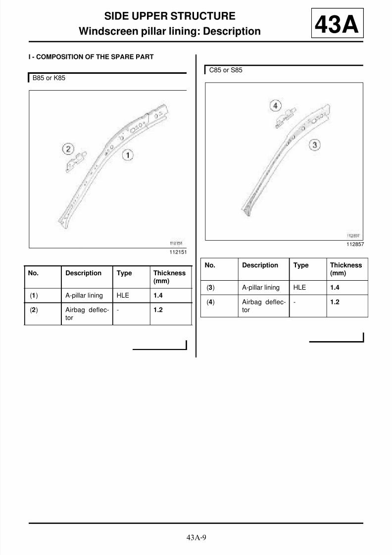
8/21/2019 Panelwork 2009+
http://slidepdf.com/reader/full/panelwork-2009 194/31343A-9
SIDE UPPER STRUCTURE
Windscreen pillar lining: Description 43AI - COMPOSITION OF THE SPARE PART
B85 or K85
112151
No. Description Type Thickness(mm)
(1) A-pillar lining HLE 1.4
(2) Airbag deflec-tor
- 1.2
C85 or S85
112857
No. Description Type Thickness(mm)
(3) A-pillar lining HLE 1.4
(4) Airbag deflec-tor
- 1.2

8/21/2019 Panelwork 2009+
http://slidepdf.com/reader/full/panelwork-2009 195/31343A-10
SIDE UPPER STRUCTURE
Windscreen pillar lining: Description 43AII - PART FITTED
1 - Partial replacement
2 - Complete replacement
C85 or S85
113216
Note:
The replacement operation presents no particulardifficulties.
B85 or K85
112695
C85 or S85
112694

8/21/2019 Panelwork 2009+
http://slidepdf.com/reader/full/panelwork-2009 196/31343A-11
SIDE UPPER STRUCTURE
Windscreen pillar lining: Description 43A
WARNING
If the mating faces of the parts to be welded are notaccessible, make EGW plug welds to replace the
original resistance welds (see MR 400).

8/21/2019 Panelwork 2009+
http://slidepdf.com/reader/full/panelwork-2009 197/31343A-12
SIDE UPPER STRUCTURE
B-pillar: General description
B85 or K85
43A
I - DESIGN OF THE STRUCTURAL COMPONENT
The B-pillar is obtained by extension from the front sec-tion body side.
WARNING
The information contained in the following descri-
bes the general repair procedure for all vehicleshaving the same design for this part.
Before reading the following general information,make sure that there are no special notes associa-ted with the vehicle. These special notes are speci-fied if necessary in other parts of the sub-sectiondealing with the component.
Note:
For a detailed description of a particular connec-
tion, see MR 400, 40A, General Information.
IMPORTANT
Before any operation, remove the front seat belts.
110591
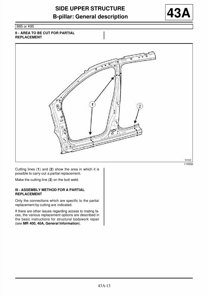
8/21/2019 Panelwork 2009+
http://slidepdf.com/reader/full/panelwork-2009 198/31343A-13
SIDE UPPER STRUCTURE
B-pillar: General description
B85 or K85
43A
II - AREA TO BE CUT FOR PARTIALREPLACEMENT
Cutting lines (1) and (2) show the area in which it ispossible to carry out a partial replacement.
Make the cutting line (2) on the butt weld.
III - ASSEMBLY METHOD FOR A PARTIALREPLACEMENT
Only the connections which are specific to the partial
replacement by cutting are indicated.If there are other issues regarding access to mating fa-ces, the various replacement options are described inthe basic instructions for structural bodywork repair(see MR 400, 40A, General Information).
110592

8/21/2019 Panelwork 2009+
http://slidepdf.com/reader/full/panelwork-2009 199/31343A-14
SIDE UPPER STRUCTURE
B-pillar: General description
B85 or K85
43A
Lines (5) and (6) on the diagram show a butt weld bycontinuous EGW welding.
Weld (6) along the butt weld line.
110593
WARNING
If the spot welds cannot be made as they were ori-ginally using an electrical spot welding machine,they should be replaced with plug welds after holes
have been drilled in the first panel.
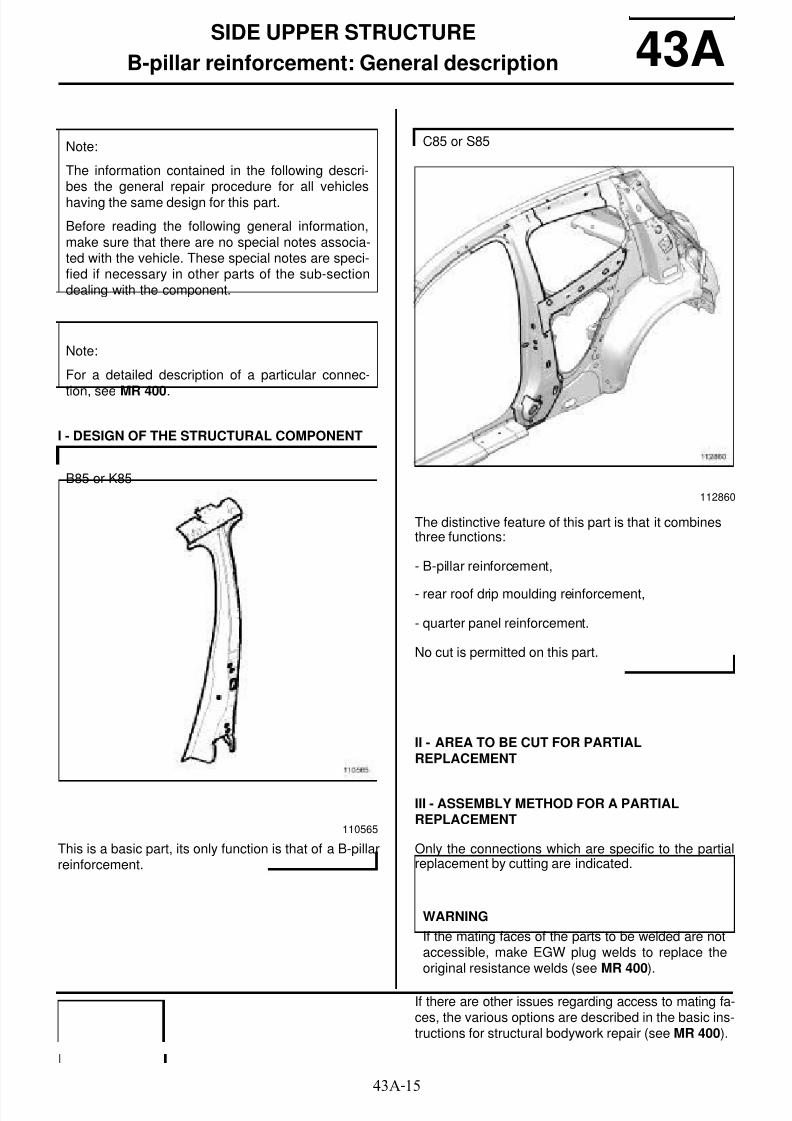
8/21/2019 Panelwork 2009+
http://slidepdf.com/reader/full/panelwork-2009 200/31343A-15
SIDE UPPER STRUCTURE
B-pillar reinforcement: General description 43A
I - DESIGN OF THE STRUCTURAL COMPONENT
This is a basic part, its only function is that of a B-pillarreinforcement.
The distinctive feature of this part is that it combinesthree functions:
- B-pillar reinforcement,
- rear roof drip moulding reinforcement,
- quarter panel reinforcement.
No cut is permitted on this part.
II - AREA TO BE CUT FOR PARTIALREPLACEMENT
III - ASSEMBLY METHOD FOR A PARTIALREPLACEMENT
Only the connections which are specific to the partialreplacement by cutting are indicated.
If there are other issues regarding access to mating fa-ces, the various options are described in the basic ins-tructions for structural bodywork repair (see MR 400).
Note:
The information contained in the following descri-bes the general repair procedure for all vehicleshaving the same design for this part.
Before reading the following general information,make sure that there are no special notes associa-ted with the vehicle. These special notes are speci-fied if necessary in other parts of the sub-sectiondealing with the component.
Note:
For a detailed description of a particular connec-
tion, see MR 400.
B85 or K85
110565
C85 or S85
112860
WARNING
If the mating faces of the parts to be welded are notaccessible, make EGW plug welds to replace theoriginal resistance welds (see MR 400).

8/21/2019 Panelwork 2009+
http://slidepdf.com/reader/full/panelwork-2009 201/31343A-16
SIDE UPPER STRUCTURE
B-pillar reinforcement: General description 43A
Line (2) on the drawing shows a butt weld by conti-
nuous EGW welding.
101971

8/21/2019 Panelwork 2009+
http://slidepdf.com/reader/full/panelwork-2009 202/31343A-17
SIDE UPPER STRUCTURE
B-pillar reinforcement: Description 43A
To replace this part, order B-pillar lining (A) .
There is only one way of replacing this part:
- complete replacement.
To replace this part, order the expanding insert (B) .
There is only one way of replacing this part:
- Complete replacement: this operation requires the
partial removal of the quarter panel lining (see Quar-
ter panel lining: Description) and the windscreen A-
pillar lining (see 43A, Side upper structure, Winds-creen pillar lining: Description, page 43A-8) .
I - COMPOSITION OF THE SPARE PART
B85 or K85
112713
C85 or S85
112720
B85 or K85
112154
No. Description Type Thickness
(mm)
(1) B-pillar reinfor-cement
VHEL 1.8
(2) B-pillar upperreinforcement
VHEL 2.8
(3) B-pillar hingereinforcement
VHEL 2
(4) Adjustmentpad
HLE 2.5

8/21/2019 Panelwork 2009+
http://slidepdf.com/reader/full/panelwork-2009 203/31343A-18
SIDE UPPER STRUCTURE
B-pillar reinforcement: Description 43A
C85 or S85
112861
No. Description Type Thickness(mm)
(5) B-pillar reinfor-cement
VHEL 1.8
(6) Quarter panelstrip reinforce-
ment
HLE 1.1
(7) Side impactretention brac-ket reinforce-ment
HLE 1.8
(8) Rear roof dripmoulding rein-forcement
HLE 1
(9) B-pillar impactreinforcement
VHEL 2.1
(10) Adjustable pad HLE 2.5

8/21/2019 Panelwork 2009+
http://slidepdf.com/reader/full/panelwork-2009 204/31343A-19
SIDE UPPER STRUCTURE
B-pillar reinforcement: Description 43AII - PART FITTED
Complete replacement
For details of body side cuts (see 43A, Side upper
structure, Body side front section: Description,page 43A-28) . Remove the B-pillar reinforcement from inside the ve-hicle.
B85 or K85
112859
112855
WARNING
If the mating faces of the parts to be welded are notaccessible, make EGW plug welds to replace theoriginal resistance welds (see MR 400).

8/21/2019 Panelwork 2009+
http://slidepdf.com/reader/full/panelwork-2009 205/31343A-20
SIDE UPPER STRUCTURE
B-pillar reinforcement: Description 43A
Remove the B-pillar reinforcement from inside the ve-hicle.
C85 or S85
112860
113215
Note:
For more detailed information on welded connec-tions with three thicknesses, see MR 400.

8/21/2019 Panelwork 2009+
http://slidepdf.com/reader/full/panelwork-2009 206/31343A-21
SIDE UPPER STRUCTURE
B-pillar lining: General description
B85 or K85
43A
DESIGN OF THE STRUCTURAL COMPONENT
This is a basic part, its only function is that of the B-pillar upper lining.
Note:
The information contained in the following descri-
bes the general repair procedure for all vehicleshaving the same design for this part.
Before reading the following general information,make sure that there are no special notes associa-ted with the vehicle. These special notes are speci-fied if necessary in other parts of the sub-sectiondealing with the component.
Note:
For a detailed description of a particular connec-tion, see MR 400.
112157
WARNING
If the mating faces of the parts to be welded are notaccessible, make EGW plug welds to replace theoriginal resistance welds (see MR 400).

8/21/2019 Panelwork 2009+
http://slidepdf.com/reader/full/panelwork-2009 207/31343A-22
SIDE UPPER STRUCTURE
Body side: General description 43A
DESIGN OF THE STRUCTURAL COMPONENT
The two parts must be welded at the joint (1) and buttwelded by continuous EGW welding.
Note:
The information contained in the following descri-bes the general repair procedure for all vehicleshaving the same design for this part.
Before reading the following general information,make sure that there are no special notes associa-ted with the vehicle. These special notes are speci-fied if necessary in other parts of the sub-sectiondealing with the component.
Note:
For a detailed description of a particular connec-tion (see MR 400).
B85 or K85
113247

8/21/2019 Panelwork 2009+
http://slidepdf.com/reader/full/panelwork-2009 208/31343A-23
SIDE UPPER STRUCTURE
Body side: General description 43A
The two parts must be welded at the joint (1) and buttwelded by continuous EGW welding.
If there are other issues regarding access to mating fa-ces, the various replacement options are described inthe basic instructions for structural bodywork repair(see MR 400).
The body side is achieved by welding the rear wing andthe body side front section.
C85 or S85
113242
WARNING
If the mating faces of the parts to be welded are notaccessible, make EGW plug welds to replace theoriginal resistance welds (see MR 400).

8/21/2019 Panelwork 2009+
http://slidepdf.com/reader/full/panelwork-2009 209/31343A-24
SIDE UPPER STRUCTURE
Body side: Description 43A
B85
113247

8/21/2019 Panelwork 2009+
http://slidepdf.com/reader/full/panelwork-2009 210/31343A-25
SIDE UPPER STRUCTURE
Body side: Description 43A
C85 or S85
113242

8/21/2019 Panelwork 2009+
http://slidepdf.com/reader/full/panelwork-2009 211/31343A-26
SIDE UPPER STRUCTURE
Body side: Description 43A
To replace this part, order the body side front section(A) with the rear wing panel (B) or the A-pillar (C) with
the rear wing panel (D) .The parts supplied are long enough to cover the partsto be replaced.
Pour le détails des méthodes, (see 43A , Side upperstructure, Body side front section: Description,page 43A-28) et (see 44A, Rear upper structure,Rear wing panel: Description, page 44A-3) .
K85
126785
Note:
For a detailed description of a particular connec-
tion, see MR 400.

8/21/2019 Panelwork 2009+
http://slidepdf.com/reader/full/panelwork-2009 212/31343A-27
SIDE UPPER STRUCTURE
Body side front section: General description
B85 or K85
43A
DESIGN OF THE STRUCTURAL COMPONENT
This part has two special features:
- it is welded under the roof,
- it is butt welded in part (1) .
Note:
The information contained in the following descri-
bes the general repair procedure for all vehicleshaving the same design for this part.
Before reading the following general information,make sure that there are no special notes associa-ted with the vehicle. These special notes are speci-fied if necessary in other parts of the sub-sectiondealing with the component.
Note:
For a detailed description of a particular connec-tion, see MR 400.
110491
WARNING
If the mating faces of the parts to be welded are notaccessible, make EGW plug welds to replace theoriginal resistance welds (see MR 400).

8/21/2019 Panelwork 2009+
http://slidepdf.com/reader/full/panelwork-2009 213/31343A-28
SIDE UPPER STRUCTURE
Body side front section: Description
B85 or K85
43A
To replace this part, order a double seal mounting (A)
in the event that the A-pillar has to be replaced.
The options for replacing this part are as follows:
- replacement of the lower section of the A-pillar
- replacement of the A-pillar,
- replacement of the B-pillar,
- replacement of the entire B-pillar,
- complete replacement.
I - COMPOSITION OF THE SPARE PART
II - PART IN POSITION
1 - Replacing the lower section of the A-pillar
113244
112160
No. Description Type Thickness(mm)
(1) Body side - 0.75
(2) Jacking pointbridge piece
Veryhighyieldstrength
2
(3) Roo f ba rmounting pad
HLE 1.5
IMPORTANTFor weld connections in three thicknesses, the spotwelds on the part replaced should be made in thesame place as for the original joint to retain itsmechanical specifications.
WARNING
If the spot welds cannot be made as they were ori-ginally using an electrical spot welding machine,they should be replaced with plug welds after holeshave been drilled in the first panel.
WARNING
The position of this cut must be observed, and isdetermined according to the position of the internalreinforcements or acoustic inserts cut.

8/21/2019 Panelwork 2009+
http://slidepdf.com/reader/full/panelwork-2009 214/31343A-29
SIDE UPPER STRUCTURE
Body side front section: Description
B85 or K85
43A
(X1) = 70 mm.
Cut (C) in front of the jacking point.
Cut B
Cut C
2 - A-pillar replacement
(X2) = 180 mm.
113027
113021
113020
113028
WARNING
When the cuts are made, keep the inner reinforce-ment in close proximity to the part to be cut.

8/21/2019 Panelwork 2009+
http://slidepdf.com/reader/full/panelwork-2009 215/31343A-30
SIDE UPPER STRUCTURE
Body side front section: Description
B85 or K85
43A
Cut D
3 - Replacing the B-pillar
This method of replacement involves replacing the B-pillar reinforcement without removing the roof.
Cut E
Cut F
113254
113023
113017
113019

8/21/2019 Panelwork 2009+
http://slidepdf.com/reader/full/panelwork-2009 216/31343A-31
SIDE UPPER STRUCTURE
Body side front section: Description
B85 or K85
43A
Cut G
4 - Replacing the complete B-pillar
This method of replacement involves completely repla-cing the B-pillar reinforcement.
Cut H
Cut I
113018
113025
113255
113022

8/21/2019 Panelwork 2009+
http://slidepdf.com/reader/full/panelwork-2009 217/31343A-32
SIDE UPPER STRUCTURE
Body side front section: Description
B85 or K85
43A
5 - Complete replacement
113026
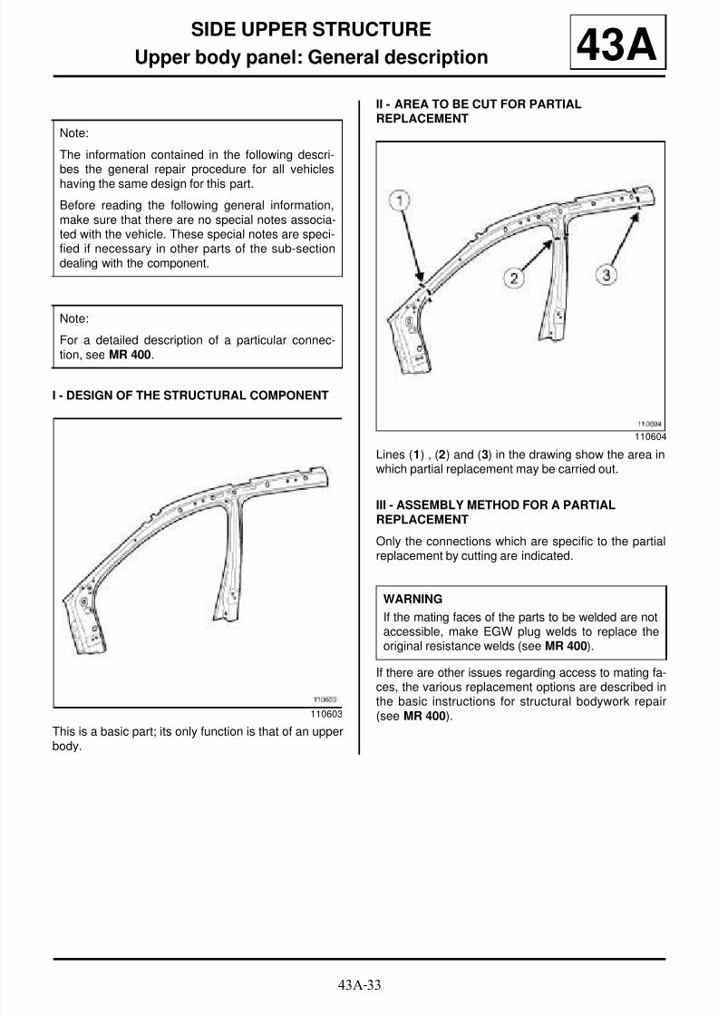
8/21/2019 Panelwork 2009+
http://slidepdf.com/reader/full/panelwork-2009 218/31343A-33
SIDE UPPER STRUCTURE
Upper body panel: General description 43A
I - DESIGN OF THE STRUCTURAL COMPONENT
This is a basic part; its only function is that of an upperbody.
II - AREA TO BE CUT FOR PARTIALREPLACEMENT
Lines (1) , (2) and (3) in the drawing show the area inwhich partial replacement may be carried out.
III - ASSEMBLY METHOD FOR A PARTIALREPLACEMENT
Only the connections which are specific to the partialreplacement by cutting are indicated.
If there are other issues regarding access to mating fa-ces, the various replacement options are described inthe basic instructions for structural bodywork repair
(see MR 400).
Note:
The information contained in the following descri-bes the general repair procedure for all vehicleshaving the same design for this part.
Before reading the following general information,make sure that there are no special notes associa-ted with the vehicle. These special notes are speci-fied if necessary in other parts of the sub-sectiondealing with the component.
Note:
For a detailed description of a particular connec-
tion, see MR 400.
110603
110604
WARNING
If the mating faces of the parts to be welded are notaccessible, make EGW plug welds to replace theoriginal resistance welds (see MR 400).

8/21/2019 Panelwork 2009+
http://slidepdf.com/reader/full/panelwork-2009 219/31343A-34
SIDE UPPER STRUCTURE
Upper body panel: General description 43A
Lines (4) , (5) and (6) on the drawing show a butt weld
by continuous EGW welding.
Weld (6) along the butt weld line.
132023
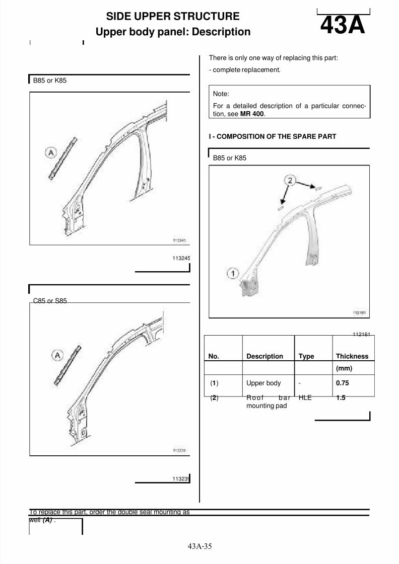
8/21/2019 Panelwork 2009+
http://slidepdf.com/reader/full/panelwork-2009 220/31343A-35
SIDE UPPER STRUCTURE
Upper body panel: Description 43A
To replace this part, order the double seal mounting aswell (A) .
There is only one way of replacing this part:
- complete replacement.
I - COMPOSITION OF THE SPARE PART
B85 or K85
113245
C85 or S85
113239
Note:
For a detailed description of a particular connec-tion, see MR 400.
B85 or K85
112161
No. Description Type Thickness
(mm)
(1) Upper body - 0.75
(2) Roo f ba rmounting pad
HLE 1.5

8/21/2019 Panelwork 2009+
http://slidepdf.com/reader/full/panelwork-2009 221/31343A-36
SIDE UPPER STRUCTURE
Upper body panel: Description 43AII - PART FITTED
Cut B
C85 or S85
113266
No. Description Type Thickness
(mm)
(3) Upper body - 0.75
(4) Roo f ba rmounting pad
HLE 1.5
Note:
For more detailed information on welded connec-tions with three thicknesses, see MR 400.
B85 or K85
113252
113021

8/21/2019 Panelwork 2009+
http://slidepdf.com/reader/full/panelwork-2009 222/31343A-37
SIDE UPPER STRUCTURE
Upper body panel: Description 43ACut C
Cut D
Cut E
113166
113253
C85 or S85
113342
113171

8/21/2019 Panelwork 2009+
http://slidepdf.com/reader/full/panelwork-2009 223/31343A-38
SIDE UPPER STRUCTURE
Upper body panel: Description 43ACut F
113253
WARNING
If the mating faces of the parts to be welded are notaccessible, make EGW plug welds to replace the
original resistance welds (see MR 400).
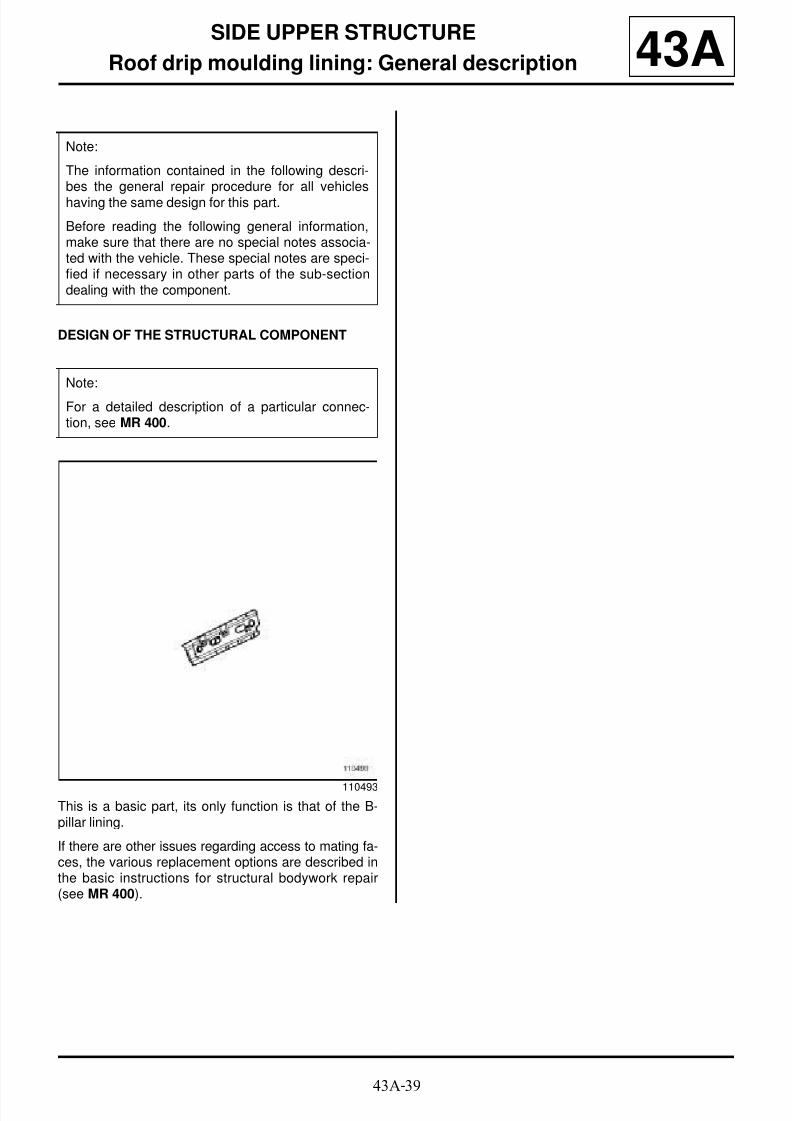
8/21/2019 Panelwork 2009+
http://slidepdf.com/reader/full/panelwork-2009 224/31343A-39
SIDE UPPER STRUCTURE
Roof drip moulding lining: General description 43A
DESIGN OF THE STRUCTURAL COMPONENT
This is a basic part, its only function is that of the B-pillar lining.
If there are other issues regarding access to mating fa-ces, the various replacement options are described inthe basic instructions for structural bodywork repair(see MR 400).
Note:
The information contained in the following descri-bes the general repair procedure for all vehicleshaving the same design for this part.
Before reading the following general information,make sure that there are no special notes associa-ted with the vehicle. These special notes are speci-fied if necessary in other parts of the sub-sectiondealing with the component.
Note:
For a detailed description of a particular connec-tion, see MR 400.
110493

8/21/2019 Panelwork 2009+
http://slidepdf.com/reader/full/panelwork-2009 225/31343A-40
SIDE UPPER STRUCTURE
Roof drip moulding lining: Description
B85 or K85
43A
There is only one way of replacing this part:
- Complete replacement: this operation requires the re-placement of the roof and the rear wing panel.
I - COMPOSITION OF THE SPARE PART
II - PART IN POSITION
112715
112163
No. Description Type Thickness(mm)
(1) Rear roof dripmouldinglining
- 0.95
(2) Rear airbag
deflector
- 0.95
113217
IMPORTANT
For weld connections in three thicknesses, the spotwelds on the part replaced should be made in thesame place as for the original joint to retain its
mechanical specifications.
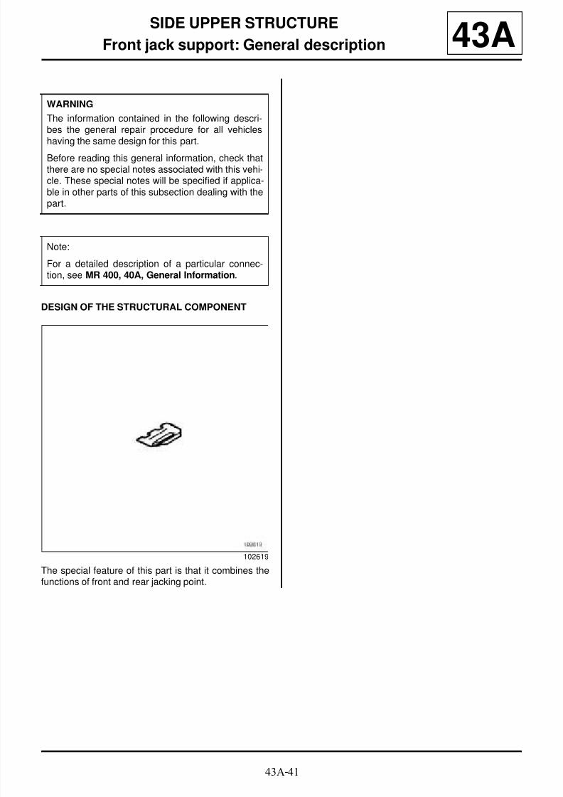
8/21/2019 Panelwork 2009+
http://slidepdf.com/reader/full/panelwork-2009 226/31343A-41
SIDE UPPER STRUCTURE
Front jack support: General description 43A
DESIGN OF THE STRUCTURAL COMPONENT
The special feature of this part is that it combines thefunctions of front and rear jacking point.
WARNING
The information contained in the following descri-bes the general repair procedure for all vehicles
having the same design for this part.
Before reading this general information, check thatthere are no special notes associated with this vehi-cle. These special notes will be specified if applica-ble in other parts of this subsection dealing with thepart.
Note:
For a detailed description of a particular connec-
tion, see MR 400, 40A, General Information.
102619

8/21/2019 Panelwork 2009+
http://slidepdf.com/reader/full/panelwork-2009 227/31344A-1
REAR UPPER STRUCTURE
Rear wing panel: General description 44A
I - DESIGN OF THE STRUCTURAL COMPONENT
This part has three special features:
- it is welded under the roof,
- it is butt welded on the body side front section.
- it is supplementary to the body side front section for acomplete body side replacement.
II - AREA TO BE CUT FOR PARTIALREPLACEMENT
Lines (1) and (2) in the drawing show the areas inwhich it is possible to carry out a partial replacement.
Note:
The information contained in the following descri-bes the general repair procedure for all vehicleshaving the same design for this part.
Before reading the following general information,make sure that there are no special notes associa-ted with the vehicle. These special notes are speci-fied if necessary in other parts of the sub-sectiondealing with the component.
Note:
For a detailed description of a particular connec-
tion, see MR 400.
107759
B85
110611
C85
113208
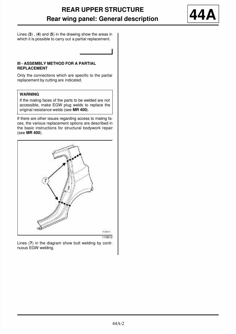
8/21/2019 Panelwork 2009+
http://slidepdf.com/reader/full/panelwork-2009 228/31344A-2
REAR UPPER STRUCTURE
Rear wing panel: General description 44ALines (3) , (4) and (5) in the drawing show the areas inwhich it is possible to carry out a partial replacement.
III - ASSEMBLY METHOD FOR A PARTIALREPLACEMENT
Only the connections which are specific to the partialreplacement by cutting are indicated.
If there are other issues regarding access to mating fa-ces, the various replacement options are described inthe basic instructions for structural bodywork repair(see MR 400).
Lines (7) in the diagram show butt welding by conti-nuous EGW welding.
WARNING
If the mating faces of the parts to be welded are notaccessible, make EGW plug welds to replace theoriginal resistance welds (see MR 400).
110612
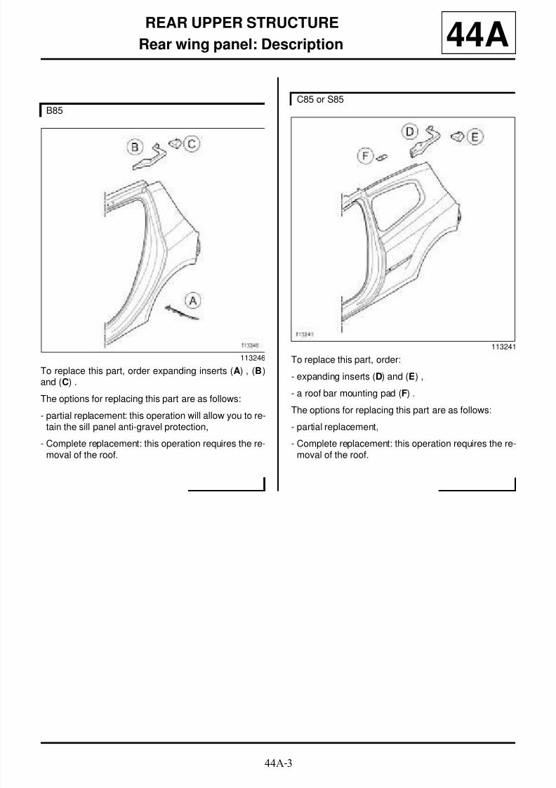
8/21/2019 Panelwork 2009+
http://slidepdf.com/reader/full/panelwork-2009 229/31344A-3
REAR UPPER STRUCTURE
Rear wing panel: Description 44A
To replace this part, order expanding inserts (A) , (B)and (C) .
The options for replacing this part are as follows:
- partial replacement: this operation will allow you to re-tain the sill panel anti-gravel protection,
- Complete replacement: this operation requires the re-moval of the roof.
To replace this part, order:
- expanding inserts (D) and (E) ,
- a roof bar mounting pad (F) .
The options for replacing this part are as follows:- partial replacement,
- Complete replacement: this operation requires the re-moval of the roof.
B85
113246
C85 or S85
113241

8/21/2019 Panelwork 2009+
http://slidepdf.com/reader/full/panelwork-2009 230/31344A-4
REAR UPPER STRUCTURE
Rear wing panel: Description 44A
Pour effectuer le remplacement de cette pièce, com-mander en supplément l’insert de custode avant, l’in-sert de custode arrière et l’insert de custode intérieur(see 40A, General information, Hollow body partsinserts: List and location of components, page
40A-16) .
The options for replacing this part are as follows:
- partial replacement,
- complete replacement.
I - COMPOSITION OF THE SPARE PART
K85
126784
Note:
For a detailed description of a particular connec-tion, see MR 400.
B85
112165
No. Description Type Thickness(mm)
(1) Rear w ingpanel
- 0.75
(2) Rear door stri-ker plate rein-forcement
- 1.5
(3) Adjustable pad HLE 2.5
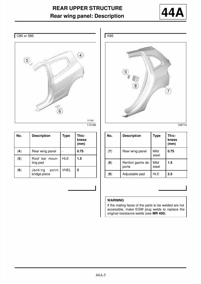
8/21/2019 Panelwork 2009+
http://slidepdf.com/reader/full/panelwork-2009 231/31344A-5
REAR UPPER STRUCTURE
Rear wing panel: Description 44A
C85 or S85
112166
No. Description Type Thic-kness(mm)
(4) Rear wing panel - 0.75
(5) Roof bar moun-ting pad
HLE 1.5
(6) Jacki ng pointbridge piece
VHEL 2
K85
126714
No. Description Type Thic-kness(mm)
(7) Rear wing panel Mildsteel
0.75
(8) Renfort gache deporte
Mildsteel
1.5
(9) Adjustable pad HLE 2.5
WARNING
If the mating faces of the parts to be welded are notaccessible, make EGW plug welds to replace theoriginal resistance welds (see MR 400).
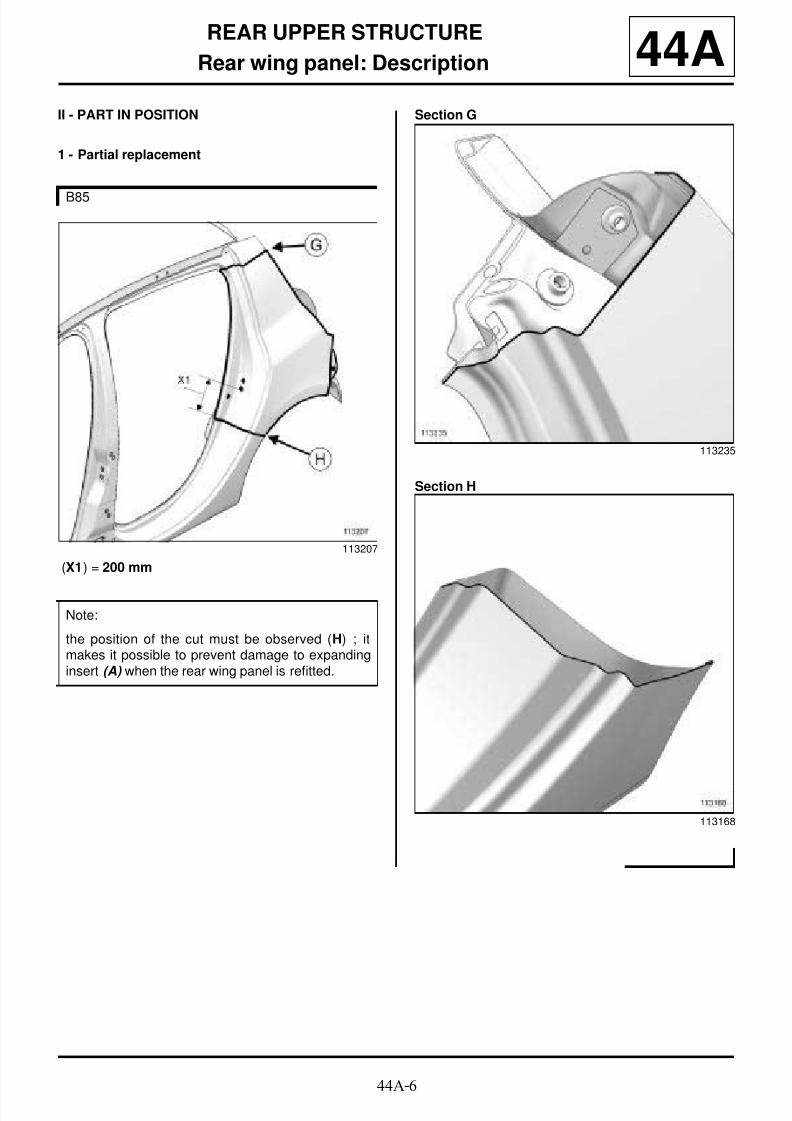
8/21/2019 Panelwork 2009+
http://slidepdf.com/reader/full/panelwork-2009 232/31344A-6
REAR UPPER STRUCTURE
Rear wing panel: Description 44AII - PART IN POSITION
1 - Partial replacement
(X1) = 200 mm
Section G
Section H
B85
113207
Note:
the position of the cut must be observed (H) ; itmakes it possible to prevent damage to expandinginsert (A) when the rear wing panel is refitted.
113235
113168

8/21/2019 Panelwork 2009+
http://slidepdf.com/reader/full/panelwork-2009 233/31344A-7
REAR UPPER STRUCTURE
Rear wing panel: Description 44A
Section I
Section J
Section K
C85 or S85
113208
Note:
avant le remplacement de l’aile arrière, coller unePLAQUE INSONORISANTE sur le panneau d’aile
arrière.
113236
113237
113169
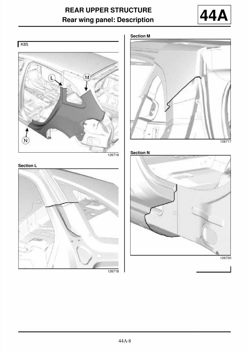
8/21/2019 Panelwork 2009+
http://slidepdf.com/reader/full/panelwork-2009 234/31344A-8
REAR UPPER STRUCTURE
Rear wing panel: Description 44A
Section L
Section M
Section N
K85
126716
126718
126717
126720

8/21/2019 Panelwork 2009+
http://slidepdf.com/reader/full/panelwork-2009 235/31344A-9
REAR UPPER STRUCTURE
Rear wing panel: Description 44A2 - Complete replacement
Section O
Section P
B85
113205
113253
113018
C85 or S85
113206

8/21/2019 Panelwork 2009+
http://slidepdf.com/reader/full/panelwork-2009 236/31344A-10
REAR UPPER STRUCTURE
Rear wing panel: Description 44ASection Q Section R
113255
K85
126715
126719
WARNING
If the mating faces of the parts to be welded are notaccessible, make EGW plug welds to replace the
original resistance welds (see MR 400).
Note:
For a detailed description of the welded connec-tions, see MR 400.

8/21/2019 Panelwork 2009+
http://slidepdf.com/reader/full/panelwork-2009 237/31344A-11
REAR UPPER STRUCTURE
Rear wing panel rain channel: General description 44A
DESIGN OF THE STRUCTURAL COMPONENT
The special feature of this part is that it is made up oftwo components:
- the rear wing panel rain channel (1) ,
- the rear lights support (2) .
If there are other issues regarding access to mating fa-ces, the various replacement options are described inthe basic instructions for structural bodywork repair(see MR 400).
Note:
The information contained in the following descri-bes the general repair procedure for all vehicleshaving the same design for this part.
Before reading the following general information,make sure that there are no special notes associa-ted with the vehicle. These special notes are speci-fied if necessary in other parts of the sub-sectiondealing with the component.
Note:
For a detailed description of a particular connec-
tion, see MR 400.
109126

8/21/2019 Panelwork 2009+
http://slidepdf.com/reader/full/panelwork-2009 238/31344A-12
REAR UPPER STRUCTURE
Rear wing panel rain channel: Description
K85
44A
The options for replacing this part are as follows:
- complete replacement.
I - COMPOSITION OF THE SPARE PART
II - PART IN POSITION
126789
126721
No. Description Type Thic-kness
(mm) (1) Gouttière laté-
rale supérieurearrière
Mildsteel
0.95
(2) Upper side heightadjuster closurepanel
Mildsteel
0.95
(3) Strut mounting
reinforcement
Mild
steel
2
126722
WARNING
If the mating faces of the parts to be welded are notaccessible, make EGW plug welds to replace theoriginal resistance welds (see MR 400).
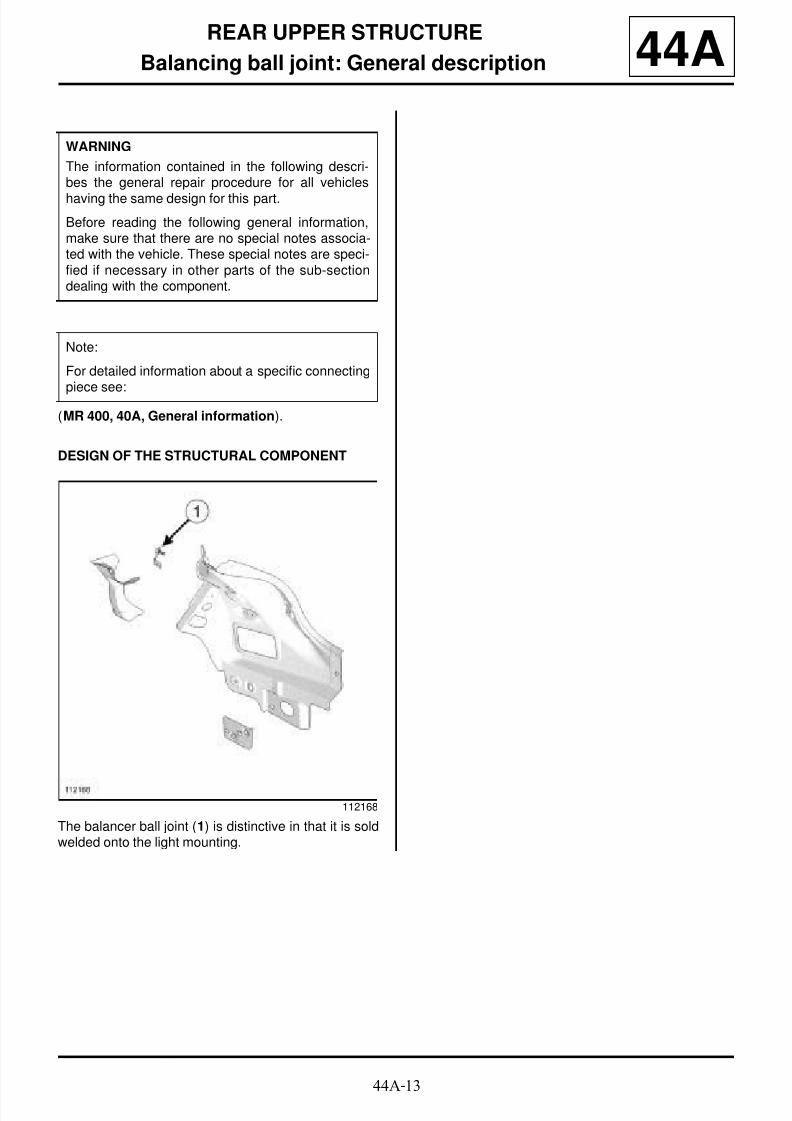
8/21/2019 Panelwork 2009+
http://slidepdf.com/reader/full/panelwork-2009 239/31344A-13
REAR UPPER STRUCTURE
Balancing ball joint: General description 44A
(MR 400, 40A, General information).
DESIGN OF THE STRUCTURAL COMPONENT
The balancer ball joint (1) is distinctive in that it is soldwelded onto the light mounting.
WARNING
The information contained in the following descri-bes the general repair procedure for all vehicles
having the same design for this part.
Before reading the following general information,make sure that there are no special notes associa-ted with the vehicle. These special notes are speci-fied if necessary in other parts of the sub-sectiondealing with the component.
Note:
For detailed information about a specific connecting
piece see:
112168

8/21/2019 Panelwork 2009+
http://slidepdf.com/reader/full/panelwork-2009 240/31344A-14
REAR UPPER STRUCTURE
Rear lights support: General description 44A
DESIGN OF THE STRUCTURAL COMPONENT
This is a basic part; its only function is that of a rear li-ghts mounting.
If there are other issues regarding access to mating fa-ces, the various replacement options are described in
the basic instructions for structural bodywork repair(see MR 400, 40A, General Information).
WARNING
The information contained in the following descri-bes the general repair procedure for all vehicles
having the same design for this part.
Before reading the following general information,make sure that there are no special notes associa-ted with the vehicle. These special notes are speci-fied if necessary in other parts of the sub-sectiondealing with the component.
Note:
For a detailed description of a particular connec-
tion, see MR 400, 40A, General Information.
109669

8/21/2019 Panelwork 2009+
http://slidepdf.com/reader/full/panelwork-2009 241/31344A-15
REAR UPPER STRUCTURE
Rear lights support: Description 44A
The options for replacing this part are as follows:
- partial replacement at natural connections this opera-tion requires the replacement of the rear end panel,
- Complete replacement: this operation requires the re-
placement of the rear wing panel.
There is only one way of replacing this part:
- Complete replacement: this operation requires the re-placement of the rear wing panel.
I - COMPOSITION OF THE SPARE PART
113267
B85 or C85 or S85
K85
B85 or C85 or S85
112168
No. Description Type Thic-kness
(mm)
(2) Rear light moun-ting
- 0.85
(3) Upper side rainchannel
- 0.95
(4) Absorber sup-port plate
VHEL 2
(5) Strut mountingreinforcement
- 2

8/21/2019 Panelwork 2009+
http://slidepdf.com/reader/full/panelwork-2009 242/31344A-16
REAR UPPER STRUCTURE
Rear lights support: Description 44A
II - PART IN POSITION
1 - Partial replacement at natural connections
2 - Complete replacement
K85
No. Description Type Thic-kness(mm)
(1) Rear light moun-ting
Mildsteel
0.85
B85 or C85 or S85
112525
B85 or C85 or S85
112524
K85
126723

8/21/2019 Panelwork 2009+
http://slidepdf.com/reader/full/panelwork-2009 243/31344A-17
REAR UPPER STRUCTURE
Rear lights support: Description 44A
WARNING
If the mating faces of the parts to be welded are notaccessible, make EGW plug welds to replace the
original resistance welds (see MR 400).

8/21/2019 Panelwork 2009+
http://slidepdf.com/reader/full/panelwork-2009 244/31344A-18
REAR UPPER STRUCTURE
Lights support lining: Description 44A
The options for replacing this part are as follows:
- partial replacement: this operation requires the repla-cement of the rear end panel,
- Complete replacement: this operation requires the re-placement of the rear wing panel.
There is only one way of replacing this part:
- Complete replacement: this operation requires the re-placement of the rear wing panel.
I - COMPOSITION OF THE SPARE PART
B85 or C85 or S85
126787
K85
126787
B85 or C85 or S85
112170

8/21/2019 Panelwork 2009+
http://slidepdf.com/reader/full/panelwork-2009 245/31344A-19
REAR UPPER STRUCTURE
Lights support lining: Description 44A
II - PART IN POSITION
1 - Partial replacement
Left side
No. Description Type Thic-kness (inmm)
(1) Lights supportlining
- 0.85
(2) Rear parcel shelfmounting bridgepiece
- 1
K85
126724
No. Description Type Thic-kness(mm)
(3) Lights supportlining
Mildsteel
0.85
(4) Absorber sup-port plate
UHLE 2
WARNING
If the mating faces of the parts to be welded are notaccessible, make EGW plug welds to replace the
original resistance welds (see MR 400).
B85 or C85 or S85
112530

8/21/2019 Panelwork 2009+
http://slidepdf.com/reader/full/panelwork-2009 246/31344A-20
REAR UPPER STRUCTURE
Lights support lining: Description 44ARight-hand side
2 - Complete replacement
113211
B85 or C85 or S85
112531
K85
126725
126726

8/21/2019 Panelwork 2009+
http://slidepdf.com/reader/full/panelwork-2009 247/31344A-21
REAR UPPER STRUCTURE
Lights support lining: Description 44AIII - POSITIONING OF LOCAL ELECTRICALEARTHS
B85 or C85 or S85
112254
K85
126698
WARNING
To avoid damaging the vehicle's electrical and elec-tronic components, disconnect the earths of any
wiring near the weld area.
Position the welding machine earth as close aspossible to the weld zone (see MR 400).
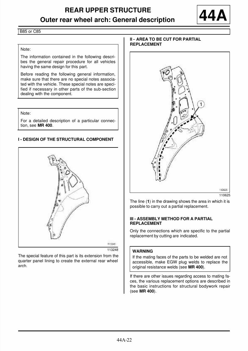
8/21/2019 Panelwork 2009+
http://slidepdf.com/reader/full/panelwork-2009 248/31344A-22
REAR UPPER STRUCTURE
Outer rear wheel arch: General description
B85 or C85
44A
I - DESIGN OF THE STRUCTURAL COMPONENT
The special feature of this part is its extension from thequarter panel lining to create the external rear wheelarch.
II - AREA TO BE CUT FOR PARTIALREPLACEMENT
The line (1) in the drawing shows the area in which it ispossible to carry out a partial replacement.
III - ASSEMBLY METHOD FOR A PARTIALREPLACEMENT
Only the connections which are specific to the partialreplacement by cutting are indicated.
If there are other issues regarding access to mating fa-ces, the various replacement options are described inthe basic instructions for structural bodywork repair(see MR 400).
Note:
The information contained in the following descri-
bes the general repair procedure for all vehicleshaving the same design for this part.
Before reading the following general information,make sure that there are no special notes associa-ted with the vehicle. These special notes are speci-fied if necessary in other parts of the sub-sectiondealing with the component.
Note:
For a detailed description of a particular connec-tion, see MR 400.
113248
110625
WARNING
If the mating faces of the parts to be welded are notaccessible, make EGW plug welds to replace theoriginal resistance welds (see MR 400).

8/21/2019 Panelwork 2009+
http://slidepdf.com/reader/full/panelwork-2009 249/31344A-23
REAR UPPER STRUCTURE
Outer rear wheel arch: General description
B85 or C85
44A
Line (2) on the diagram shows partial replacement anda weld by joggling with plug welds at regular intervals.
110626
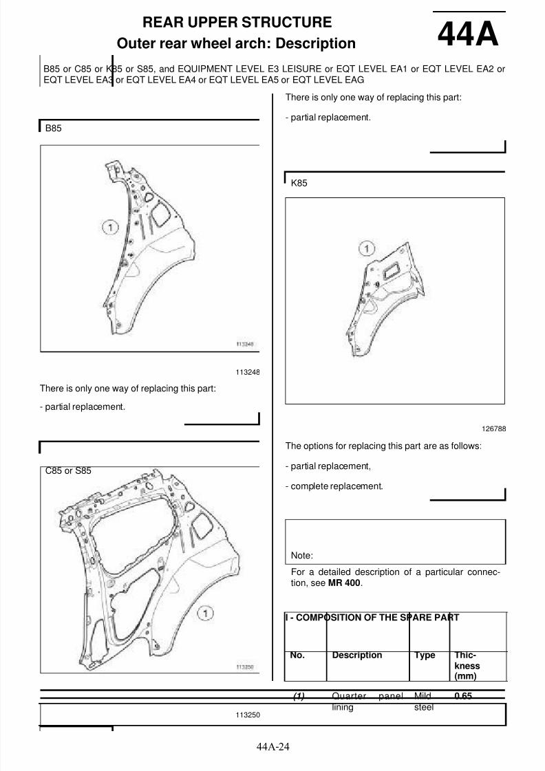
8/21/2019 Panelwork 2009+
http://slidepdf.com/reader/full/panelwork-2009 250/31344A-24
REAR UPPER STRUCTURE
Outer rear wheel arch: Description
B85 or C85 or K85 or S85, and EQUIPMENT LEVEL E3 LEISURE or EQT LEVEL EA1 or EQT LEVEL EA2 orEQT LEVEL EA3 or EQT LEVEL EA4 or EQT LEVEL EA5 or EQT LEVEL EAG
44A
There is only one way of replacing this part:
- partial replacement.
There is only one way of replacing this part:
- partial replacement.
The options for replacing this part are as follows:
- partial replacement,
- complete replacement.
I - COMPOSITION OF THE SPARE PART
B85
113248
C85 or S85
113250
K85
126788
Note:
For a detailed description of a particular connec-tion, see MR 400.
No. Description Type Thic-kness
(mm)
(1) Quarter panellining
Mildsteel
0.65

8/21/2019 Panelwork 2009+
http://slidepdf.com/reader/full/panelwork-2009 251/31344A-25
REAR UPPER STRUCTURE
Outer rear wheel arch: Description
B85 or C85 or K85 or S85, and EQUIPMENT LEVEL E3 LEISURE or EQT LEVEL EA1 or EQT LEVEL EA2 orEQT LEVEL EA3 or EQT LEVEL EA4 or EQT LEVEL EA5 or EQT LEVEL EAG
44A
II - PART IN POSITION
1 - Partial replacement
(X1) = 15 mm
Make the cut from inside the wheel arch so as not todamage the reinforcement nearby.
(X1) = 15 mm
Make the cut from inside the wheel arch so as not todamage the reinforcement nearby.
P = pitch
WARNINGIf the mating faces of the parts to be welded are notaccessible, make EGW plug welds to replace theoriginal resistance welds (see MR 400).
B85
113010
C85 or S85
113009
K85
126728

8/21/2019 Panelwork 2009+
http://slidepdf.com/reader/full/panelwork-2009 252/31344A-26
REAR UPPER STRUCTURE
Outer rear wheel arch: Description
B85 or C85 or K85 or S85, and EQUIPMENT LEVEL E3 LEISURE or EQT LEVEL EA1 or EQT LEVEL EA2 orEQT LEVEL EA3 or EQT LEVEL EA4 or EQT LEVEL EA5 or EQT LEVEL EAG
44A
D = distance covered
2 - Complete replacement
III - POSITIONING OF LOCAL ELECTRICALEARTHS
K85
126727
B85 or C85 or S85
112254
K85
126698

8/21/2019 Panelwork 2009+
http://slidepdf.com/reader/full/panelwork-2009 253/31344A-27
REAR UPPER STRUCTURE
Outer rear wheel arch: Description
B85 or C85 or K85 or S85, and EQUIPMENT LEVEL E3 LEISURE or EQT LEVEL EA1 or EQT LEVEL EA2 orEQT LEVEL EA3 or EQT LEVEL EA4 or EQT LEVEL EA5 or EQT LEVEL EAG
44A
WARNING
To avoid damaging the vehicle's electrical and elec-tronic components, disconnect the earths of anywiring near the weld area.
Position the welding machine earth as close aspossible to the weld zone (see MR 400).

8/21/2019 Panelwork 2009+
http://slidepdf.com/reader/full/panelwork-2009 254/31344A-28
REAR UPPER STRUCTURE
Outer rear wheel arch: Description
C85, and EQUIPMENT LEVEL EAC or EQT LEVEL SPORT
44A
I - COMPOSITION OF THE SPARE PART
II - PART FITTED
Special notes on the outer rear wheel arch
When replacing this component, the Spare Parts De-partment only supplies the outer rear wheel arch linerswithout studs for mounting the rear wheel arch liners.
It is essential to fit studs onto the spare part (see MR400, Bodywork structure repair basics, 40A, Gene-ral information, Screwed connection with welded
stud: Repair) or (see MR 400, Bodywork structurerepair basics, 40A, General information, Screwedconnection with crimped mounting: Fitting).
116927
No. Description Type Thickness(mm)
(1) Out er rearwheel arch
Mildsteel
0.65
116926
WARNING
If the spot welds cannot be made as they were ori-
ginally using an electrical spot welding machine,they should be replaced with plug welds after holeshave been drilled in the first panel.
120617

8/21/2019 Panelwork 2009+
http://slidepdf.com/reader/full/panelwork-2009 255/31344A-29
REAR UPPER STRUCTURE
Outer rear wheel arch: Description
C85, and EQUIPMENT LEVEL EAC or EQT LEVEL SPORT
44A
Details of the stud (2)
Details of the stud (3)
III - POSITIONING OF LOCAL ELECTRICALEARTHS
120618
120619
112255
IMPORTANT
To avoid damaging the vehicle's electric and elec-tronic components, the battery and the earths of
any wiring harness near the weld area must be dis-connected.
The earth of the welding machine must be placedas close as possible to the weld area.

8/21/2019 Panelwork 2009+
http://slidepdf.com/reader/full/panelwork-2009 256/31344A-30
REAR UPPER STRUCTURE
Body side rear lining: Description 44A
There is only one way of replacing this part:
- complete replacement.
The options for replacing this part are as follows:
- partial replacement: this operation complements thereplacement of the B-pillar reinforcement,
- complete replacement.
There is only one way of replacing this part:
- complete replacement.
B85
113249
C85 or S85
113251
K85

8/21/2019 Panelwork 2009+
http://slidepdf.com/reader/full/panelwork-2009 257/31344A-31
REAR UPPER STRUCTURE
Body side rear lining: Description 44AI - COMPOSITION OF THE SPARE PART
B85
116180
No. Description Type Thickness(mm)
(1) Quarter pan ellining
Mildsteel
0.65
(2) Side roof rail rear
lining
Mild
steel
0.95
(3) Rear a i rba gdeflector
Mildsteel
0.95
(4) Quarter pan elreinforcement
Mildsteel
0.7
(5) Rear parcel shelfmounting bridgepiece
Mildsteel
1
(6) Lights support
lining
Mild
steel
0.85
(7) Quarter pan elupper sectionrear reinforce-ment
Mildsteel
1.2
(8) Inner rear wheelarch
HLE 0.75
(9) Shock absorberconnecting brac-ket
HLE 1.2
(10) Shock absorbercup mounting
HLE 2
(11) Rear seatbackhinge mounting
HLE 1.2
(12) Rear seatbackmounting reinfor-cement
Mildsteel
2
No. Description Type Thickness(mm)
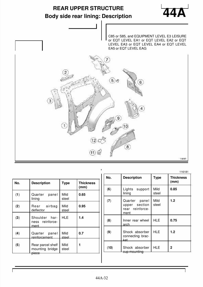
8/21/2019 Panelwork 2009+
http://slidepdf.com/reader/full/panelwork-2009 258/31344A-32
REAR UPPER STRUCTURE
Body side rear lining: Description 44A
C85 or S85, and EQUIPMENT LEVEL E3 LEISUREor EQT LEVEL EA1 or EQT LEVEL EA2 or EQTLEVEL EA3 or EQT LEVEL EA4 or EQT LEVEL
EA5 or EQT LEVEL EAG
116181
No. Description Type Thickness(mm)
(1) Quarter pane llining
Mildsteel
0.65
(2) Rear a i rbagdeflector
Mildsteel
0.95
(3) Shoulder har-ness reinforce-ment
HLE 1.4
(4) Quarter pane lreinforcement
Mildsteel
0.7
(5) Rear parcel shelfmounting bridgepiece
Mildsteel
1
(6) Lights supportlining
Mildsteel
0.85
(7) Quarter pane lupper sectionrear reinforce-ment
Mildsteel
1.2
(8) Inner rear wheelarch
HLE 0.75
(9) Shock absorberconnecting brac-ket
HLE 1.2
(10) Shock absorber
cup mounting
HLE 2
No. Description Type Thickness(mm)

8/21/2019 Panelwork 2009+
http://slidepdf.com/reader/full/panelwork-2009 259/31344A-33
REAR UPPER STRUCTURE
Body side rear lining: Description 44A
(11) Rear seatbackhinge mounting
HLE 1.2
(12) Rear seatbackmounting reinfor-cement
Mildsteel
2
No. Description Type Thickness(mm)
C85, and EQUIPMENT LEVEL EAC or EQT LEVEL
SPORT
116928
No. Description Type Thickness(mm)
(1) Quarter pane llining
Mildsteel
0.65
(2) Rear a i rbagdeflector
Mildsteel
0.95
(3) Shoulder har-ness reinforce-ment
HLE 1.4
(4) Outer wheel arch Mildsteel
0.65
(5) Quarter pane lupper sectionrear reinforce-ment
Mildsteel
1.2
(6) Rear parcel shelfmounting bridgepiece
Mildsteel
1
(7) Lights supportlining
Mildsteel
0.85
(8) Quarter pane lreinforcement
Mildsteel
0.7
No. Description Type Thickness(mm)

8/21/2019 Panelwork 2009+
http://slidepdf.com/reader/full/panelwork-2009 260/31344A-34
REAR UPPER STRUCTURE
Body side rear lining: Description 44A
(9) Inner rear wheelarch
HLE 0.75
(10) Shock absorbercup mounting
HLE 2
(11) Shock absorberconnecting brac-ket
HLE 1.2
(12) Rear seatbackhinge mounting
HLE 1.2
(13) Rear seatbackmounting reinfor-cement
Mildsteel
2
No. Description Type Thickness(mm)
K85
126730

8/21/2019 Panelwork 2009+
http://slidepdf.com/reader/full/panelwork-2009 261/31344A-35
REAR UPPER STRUCTURE
Body side rear lining: Description 44A
II - PART FITTED
1 - Partial replacement
No. Type Des-crip-tion
Thic-kness(mm)
(14) Left-hand C-pillarreinforcement
Mildsteel
1.2
(15) Roof drip moul-ding lining
Mildsteel
0.95
(16) Airbag deflector Mildsteel
0.95
(17) Luggage retainermounting
Mildsteel
1.2
(18) Quarte r pan ellining Mildsteel 0.6
(19) Seat belt inertiareel anchoragereinforcement
HLE 1.5
(20) Quarte r pan elrear upper rein-forcement
(21) Outer wheel arch Mildsteel
0.67
(22) Seatback moun-ting reinforce-ment plate
(23) Outer wheel archreinforcement
Mildsteel
1
(24) Inner wheel arch HLE 0.75
(25) Left-hand seat-back h ingemounting
HLE 1.5
(26) Seatback retai-ning hook
THLE 3
(27) Seatback moun-ting reinforce-ment
Mildsteel
2
(28) Shock absorberturret mounting
HLE 2
(29) Shock absorberconnecting brac-
ket
HLE 1.2
(30) Removable floorreinforcement
Mildsteel
1
(31) Wheel arch clo-sure panel com-ponent
Mildsteel
1
(32) Absorber sup-port plate
UHLE 2
(33) Lights supportlining
Mildsteel
0.85
C85 or S85, and EQUIPMENT LEVEL E3 LEISUREor EQT LEVEL EA1 or EQT LEVEL EA2 or EQTLEVEL EA3 or EQT LEVEL EA4 or EQT LEVELEA5 or EQT LEVEL EAG
113214
No. Type Des-crip-tion
Thic-kness(mm)

8/21/2019 Panelwork 2009+
http://slidepdf.com/reader/full/panelwork-2009 262/31344A-36
REAR UPPER STRUCTURE
Body side rear lining: Description 44ASection A
Section B
Section C
2 - Complete replacement
113106
113107
113108
B85
113204

8/21/2019 Panelwork 2009+
http://slidepdf.com/reader/full/panelwork-2009 263/31344A-37
REAR UPPER STRUCTURE
Body side rear lining: Description 44A
C85 or S85, and EQUIPMENT LEVEL E3 LEISUREor EQT LEVEL EA1 or EQT LEVEL EA2 or EQTLEVEL EA3 or EQT LEVEL EA4 or EQT LEVEL
EA5 or EQT LEVEL EAG
113203

8/21/2019 Panelwork 2009+
http://slidepdf.com/reader/full/panelwork-2009 264/31344A-38
REAR UPPER STRUCTURE
Body side rear lining: Description 44A
Detailed view
3 - Special features of the body side rear lining
When replacing this component, the Parts Depart-ment only supplies the body side rear lining withoutstuds for mounting the rear wheel arch liners.
K85
126731
126732
WARNING
If the mating faces of the parts to be welded are notaccessible, make EGW plug welds to replace theoriginal resistance welds (see MR 400).
Note:
For more detailed information on welded connec-tions with three thicknesses, see MR 400.
C85, and EQUIPMENT LEVEL EAC or EQT LEVELSPORT
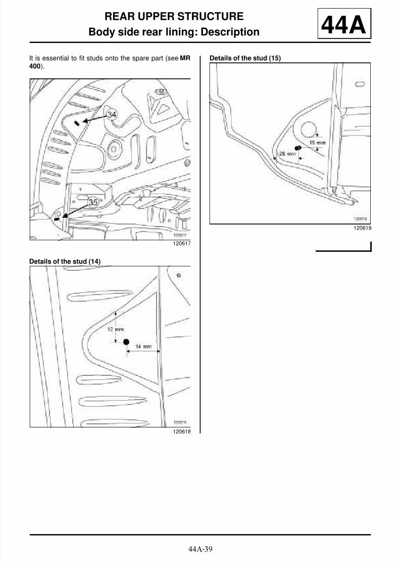
8/21/2019 Panelwork 2009+
http://slidepdf.com/reader/full/panelwork-2009 265/31344A-39
REAR UPPER STRUCTURE
Body side rear lining: Description 44AIt is essential to fit studs onto the spare part (see MR400).
Details of the stud (14)
Details of the stud (15)
120617
120618
120619
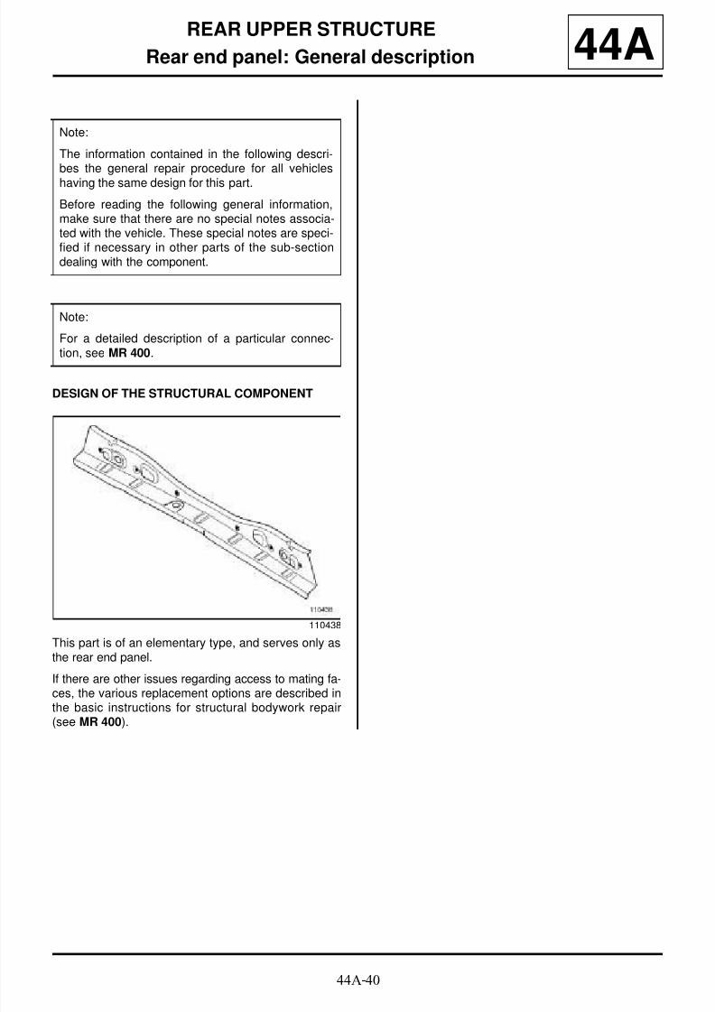
8/21/2019 Panelwork 2009+
http://slidepdf.com/reader/full/panelwork-2009 266/31344A-40
REAR UPPER STRUCTURE
Rear end panel: General description 44A
DESIGN OF THE STRUCTURAL COMPONENT
This part is of an elementary type, and serves only asthe rear end panel.
If there are other issues regarding access to mating fa-ces, the various replacement options are described in
the basic instructions for structural bodywork repair(see MR 400).
Note:
The information contained in the following descri-bes the general repair procedure for all vehicleshaving the same design for this part.
Before reading the following general information,make sure that there are no special notes associa-ted with the vehicle. These special notes are speci-fied if necessary in other parts of the sub-sectiondealing with the component.
Note:
For a detailed description of a particular connec-
tion, see MR 400.
110438

8/21/2019 Panelwork 2009+
http://slidepdf.com/reader/full/panelwork-2009 267/31344A-41
REAR UPPER STRUCTURE
Rear end panel: Description 44A
There is only one way of replacing this part:
- complete replacement.
I - COMPOSITION OF THE SPARE PART
II - PART FITTED
112603
B85 or C85 or S85
No. Description Type Thic-kness(mm)
(1) Rear endpanel
HLE 0.85
K85
No. Description Type Thic-kness(mm)
(1) Rear endpanel
HLE 0.95
B85 or C85 or S85
113212
K85
126735

8/21/2019 Panelwork 2009+
http://slidepdf.com/reader/full/panelwork-2009 268/31344A-42
REAR UPPER STRUCTURE
Rear end panel: Description 44A
WARNING
If the mating faces of the parts to be welded are notaccessible, make EGW plug welds to replace the
original resistance welds (see MR 400).
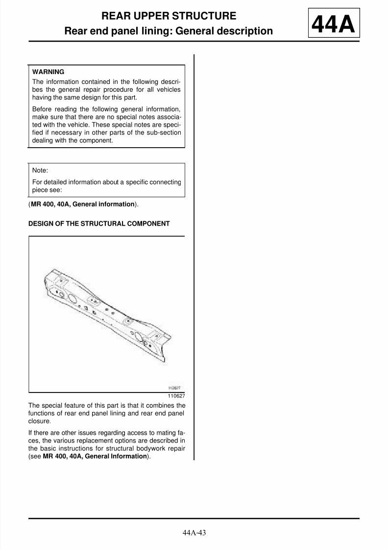
8/21/2019 Panelwork 2009+
http://slidepdf.com/reader/full/panelwork-2009 269/31344A-43
REAR UPPER STRUCTURE
Rear end panel lining: General description 44A
(MR 400, 40A, General information).
DESIGN OF THE STRUCTURAL COMPONENT
The special feature of this part is that it combines thefunctions of rear end panel lining and rear end panelclosure.
If there are other issues regarding access to mating fa-ces, the various replacement options are described inthe basic instructions for structural bodywork repair(see MR 400, 40A, General Information).
WARNING
The information contained in the following descri-bes the general repair procedure for all vehicles
having the same design for this part.
Before reading the following general information,make sure that there are no special notes associa-ted with the vehicle. These special notes are speci-fied if necessary in other parts of the sub-sectiondealing with the component.
Note:
For detailed information about a specific connecting
piece see:
110627
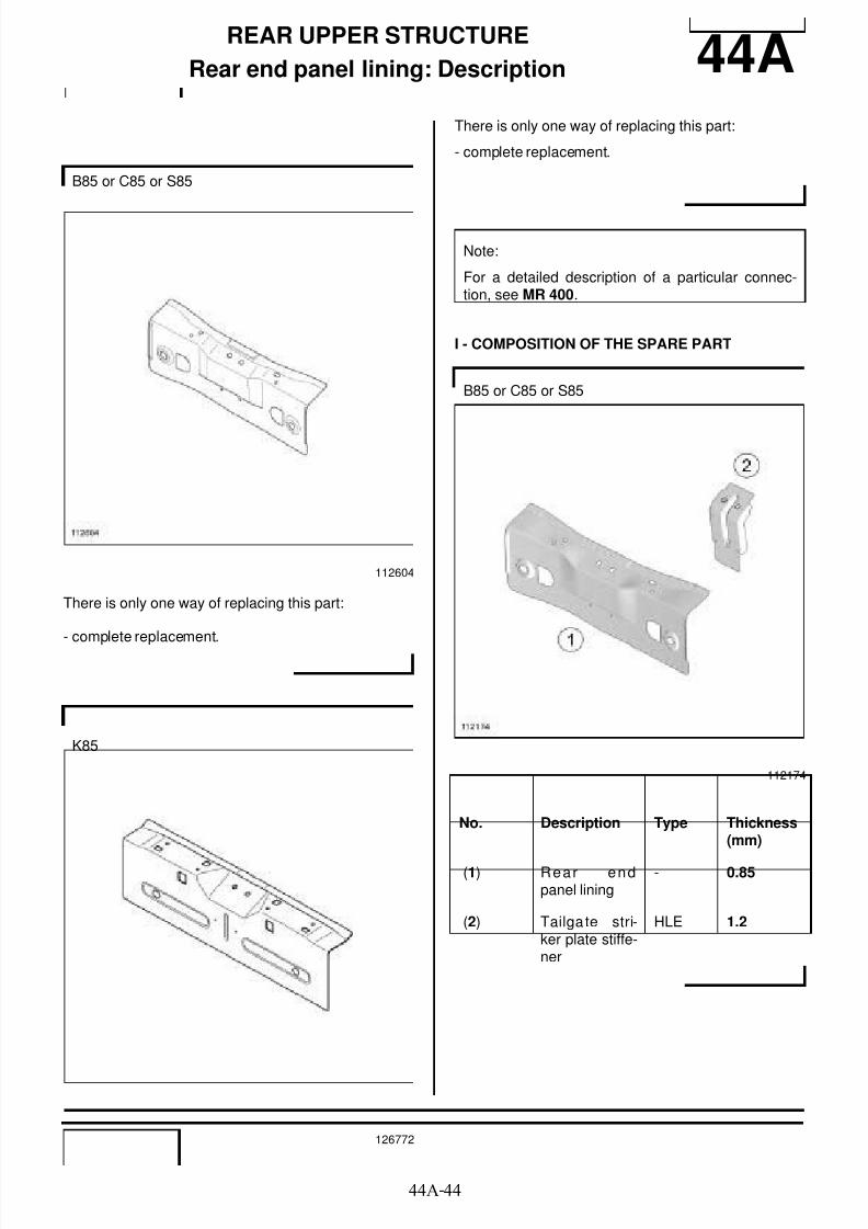
8/21/2019 Panelwork 2009+
http://slidepdf.com/reader/full/panelwork-2009 270/31344A-44
REAR UPPER STRUCTURE
Rear end panel lining: Description 44A
There is only one way of replacing this part:
- complete replacement.
There is only one way of replacing this part:
- complete replacement.
I - COMPOSITION OF THE SPARE PART
B85 or C85 or S85
112604
K85
126772
Note:
For a detailed description of a particular connec-tion, see MR 400.
B85 or C85 or S85
112174
No. Description Type Thickness(mm)
(1) Rear endpanel lining
- 0.85
(2) Tailga te stri-ker plate stiffe-ner
HLE 1.2
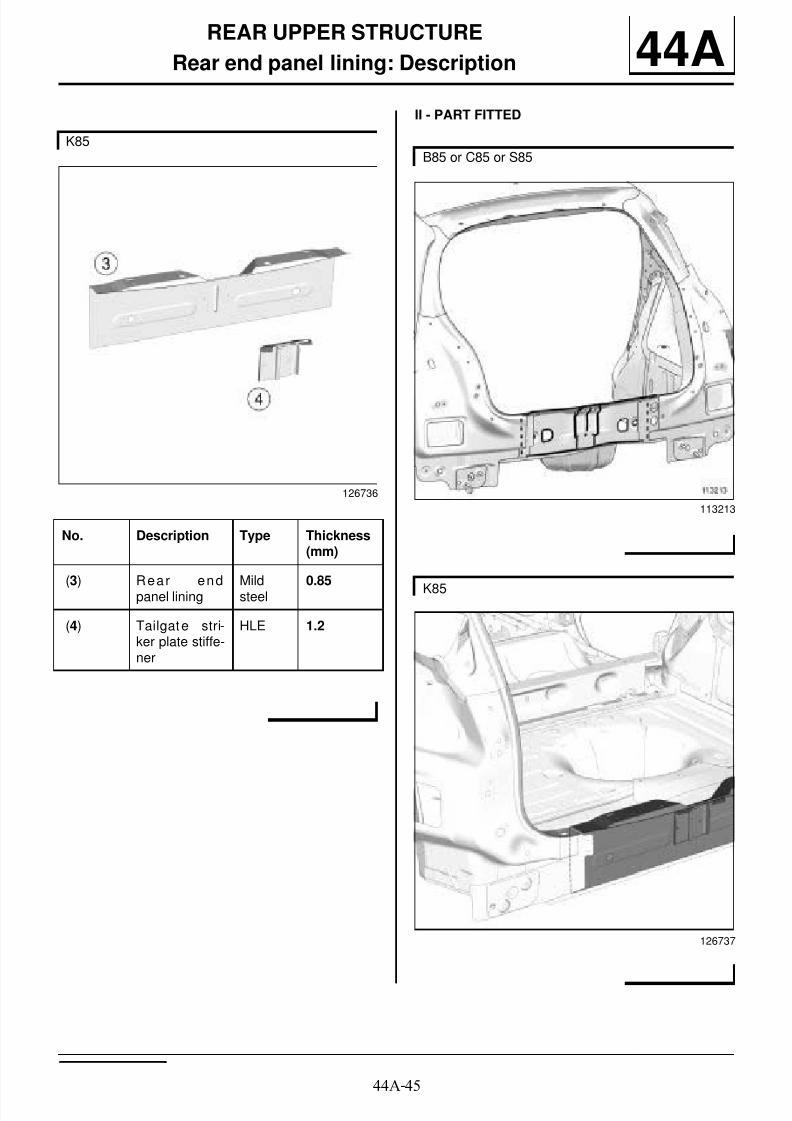
8/21/2019 Panelwork 2009+
http://slidepdf.com/reader/full/panelwork-2009 271/31344A-45
REAR UPPER STRUCTURE
Rear end panel lining: Description 44AII - PART FITTED
K85
126736
No. Description Type Thickness(mm)
(3) Rear endpanel lining
Mildsteel
0.85
(4) Tailgate stri-ker plate stiffe-ner
HLE 1.2
B85 or C85 or S85
113213
K85
126737
8/21/2019 Panelwork 2009+
http://slidepdf.com/reader/full/panelwork-2009 272/31344A-46
REAR UPPER STRUCTURE
Rear end panel lining: Description 44A
WARNING
If the mating faces of the parts to be welded are notaccessible, make EGW plug welds to replace the
original resistance welds (see MR 400).

8/21/2019 Panelwork 2009+
http://slidepdf.com/reader/full/panelwork-2009 273/31345A-1
TOP OF BODY
Roof: General description 45A
DESIGN OF THE STRUCTURAL COMPONENT
This is a basic part; its only function is that of a roof.
The roof is welded onto the body sides.
There are also models with a space for a sunroof.
If there are other issues regarding access to mating fa-ces, the various replacement options are described inthe basic instructions for structural bodywork repair(see MR 400).
Note:
The information contained in the following descri-bes the general repair procedure for all vehicleshaving the same design for this part.
Before reading the following general information,make sure that there are no special notes associa-ted with the vehicle. These special notes are speci-fied if necessary in other parts of the sub-sectiondealing with the component.
Note:
For a detailed description of a particular connec-
tion, see MR 400.
112147

8/21/2019 Panelwork 2009+
http://slidepdf.com/reader/full/panelwork-2009 274/31345A-2
TOP OF BODY
Roof: Description 45A
B85, and NORMAL ROOF
112609
C85 or S85, and NORMAL ROOF
112607
K85, and NORMAL ROOF
126790
B85, and PANORAMIC SUNROOF
112610
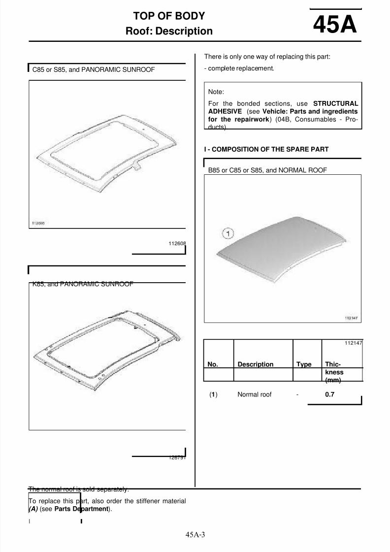
8/21/2019 Panelwork 2009+
http://slidepdf.com/reader/full/panelwork-2009 275/31345A-3
TOP OF BODY
Roof: Description 45A
The normal roof is sold separately.
To replace this part, also order the stiffener material(A) (see Parts Department).
There is only one way of replacing this part:
- complete replacement.
I - COMPOSITION OF THE SPARE PART
C85 or S85, and PANORAMIC SUNROOF
112608
K85, and PANORAMIC SUNROOF
126791
Note:
For the bonded sections, use STRUCTURALADHESIVE (see Vehicle: Parts and ingredientsfor the repairwork) (04B, Consumables - Pro-ducts).
B85 or C85 or S85, and NORMAL ROOF
112147
No. Description Type Thic-kness(mm)
(1) Normal roof - 0.7

8/21/2019 Panelwork 2009+
http://slidepdf.com/reader/full/panelwork-2009 276/31345A-4
TOP OF BODY
Roof: Description 45A
K85, and NORMAL ROOF
126739
No. Description Type Thic-kness(mm)
(2) Normal roof Mildsteel
0.75
(3) Roof bar moun-ting reinforce-ment
HLE 1.5
B85 or C85 or S85, and PANORAMIC SUNROOF
112146
No. Description Type Thic-kness(mm)
(4) Roof with sunroof - 0.7
(5) Sunroof reinfor-cement rails
- 1

8/21/2019 Panelwork 2009+
http://slidepdf.com/reader/full/panelwork-2009 277/31345A-5
TOP OF BODY
Roof: Description 45AII - PART FITTED
Rear section
K85, and PANORAMIC SUNROOF
126741
No. Description Type Thic-kness(mm)
(6) Roof with sunroof Mildsteel
0.75
(7) Roof reinforce-ment rail
Mildsteel
1
(8) Water drain pipe Mildsteel
1
(9) Roof bar moun-ting reinforce-ment
HLE 1.5
B85, and NORMAL ROOF
112683
112684

8/21/2019 Panelwork 2009+
http://slidepdf.com/reader/full/panelwork-2009 278/31345A-6
TOP OF BODY
Roof: Description 45A
Cutting the roof tab
C85 or S85, and NORMAL ROOF
112682
112854
Note:
The roof is sold with a tab on each side to prevent itfrom bending during transportation.
Cut this away before fitting the roof in position
K85, and NORMAL ROOF
126738
K85, and PANORAMIC SUNROOF
126740
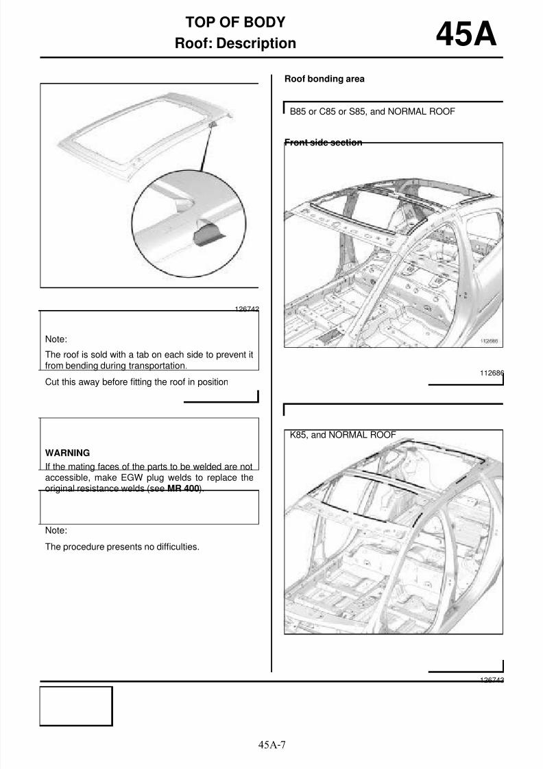
8/21/2019 Panelwork 2009+
http://slidepdf.com/reader/full/panelwork-2009 279/31345A-7
TOP OF BODY
Roof: Description 45ARoof bonding area
Front side section
126742
Note:
The roof is sold with a tab on each side to prevent itfrom bending during transportation.
Cut this away before fitting the roof in position
WARNING
If the mating faces of the parts to be welded are notaccessible, make EGW plug welds to replace theoriginal resistance welds (see MR 400).
Note:
The procedure presents no difficulties.
B85 or C85 or S85, and NORMAL ROOF
112686
K85, and NORMAL ROOF
126743

8/21/2019 Panelwork 2009+
http://slidepdf.com/reader/full/panelwork-2009 280/31345A-8
TOP OF BODY
Roof: Description 45A
Front side section Rear section
B85 or C85 or S85, and PANORAMIC SUNROOF
112685
K85, and PANORAMIC SUNROOF
126745
B85 or C85 or S85
112688
114469
Note:
Apply a bead (10) of STRUCTURAL ADHESIVE toeach side of the vehicle before refitting the roof (seeVehicle: Parts and consumables for repair) (04B,
Consumables - Products).
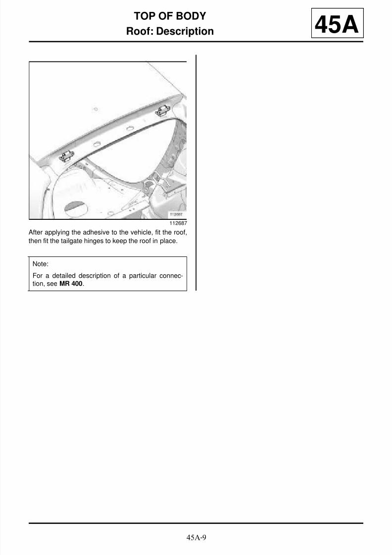
8/21/2019 Panelwork 2009+
http://slidepdf.com/reader/full/panelwork-2009 281/31345A-9
TOP OF BODY
Roof: Description 45A
After applying the adhesive to the vehicle, fit the roof,
then fit the tailgate hinges to keep the roof in place.
112687
Note:
For a detailed description of a particular connec-tion, see MR 400.
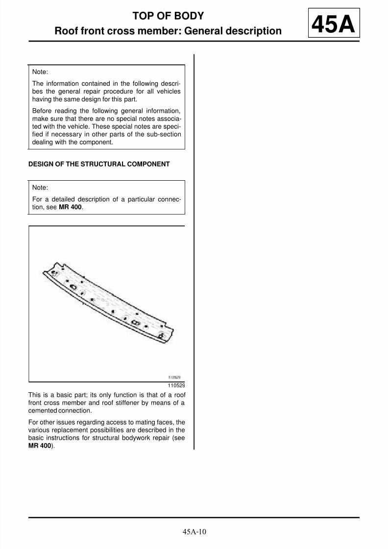
8/21/2019 Panelwork 2009+
http://slidepdf.com/reader/full/panelwork-2009 282/31345A-10
TOP OF BODY
Roof front cross member: General description 45A
DESIGN OF THE STRUCTURAL COMPONENT
This is a basic part; its only function is that of a rooffront cross member and roof stiffener by means of acemented connection.
For other issues regarding access to mating faces, thevarious replacement possibilities are described in thebasic instructions for structural bodywork repair (seeMR 400).
Note:
The information contained in the following descri-bes the general repair procedure for all vehicleshaving the same design for this part.
Before reading the following general information,make sure that there are no special notes associa-ted with the vehicle. These special notes are speci-fied if necessary in other parts of the sub-sectiondealing with the component.
Note:
For a detailed description of a particular connec-tion, see MR 400.
110529
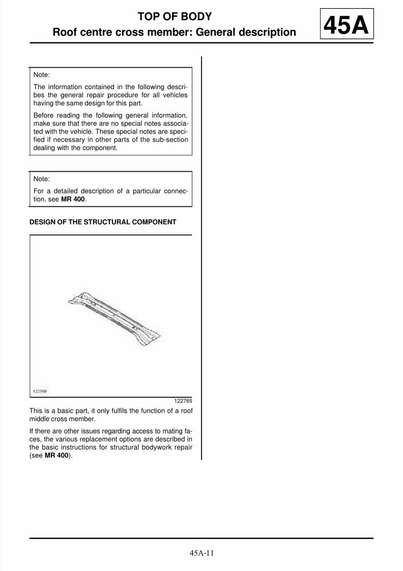
8/21/2019 Panelwork 2009+
http://slidepdf.com/reader/full/panelwork-2009 283/31345A-11
TOP OF BODY
Roof centre cross member: General description 45A
DESIGN OF THE STRUCTURAL COMPONENT
This is a basic part, it only fulfils the function of a roofmiddle cross member.
If there are other issues regarding access to mating fa-ces, the various replacement options are described inthe basic instructions for structural bodywork repair(see MR 400).
Note:
The information contained in the following descri-bes the general repair procedure for all vehicleshaving the same design for this part.
Before reading the following general information,make sure that there are no special notes associa-ted with the vehicle. These special notes are speci-fied if necessary in other parts of the sub-sectiondealing with the component.
Note:
For a detailed description of a particular connec-
tion, see MR 400.
122769

8/21/2019 Panelwork 2009+
http://slidepdf.com/reader/full/panelwork-2009 284/31345A-12
TOP OF BODY
Roof centre cross member: Description 45A
There is only one way of replacing this part:
- complete replacement.
I - COMPOSITION OF THE SPARE PART
NORMAL ROOF
112723
PANORAMIC SUNROOF
113008
NORMAL ROOF
No. Description Type Thic-kness(mm)
(1) Normal roof cen-tre cross member
VHEL 1.8
PANORAMIC SUNROOF
No. Description Type Thic-kness(mm)
(2) Roof centre crossmember closurepanel
HLE 1.5
(3) Roof centre crossmember (with
sunroof)
HLE 1
Note:
There is no specific method for this replacement; allthe joints are made in the same way as originally.

8/21/2019 Panelwork 2009+
http://slidepdf.com/reader/full/panelwork-2009 285/31345A-13
TOP OF BODY
Roof centre cross member: Description 45AII - PART IN POSITION
NORMAL ROOF
112691
PANORAMIC SUNROOF
112693
WARNING
If the mating faces of the parts to be welded are notaccessible, make EGW plug welds to replace the
original resistance welds (see MR 400).

8/21/2019 Panelwork 2009+
http://slidepdf.com/reader/full/panelwork-2009 286/31345A-14
TOP OF BODY
Roof rear cross member: General description 45A
DESIGN OF THE STRUCTURAL COMPONENT
This is a basic part; its only function is that of roof rearcross member as well as roof stiffener by means of acemented connection.
For other issues regarding access to mating faces, thevarious replacement possibilities are described in thebasic instructions for structural bodywork repair (seeMR 400).
Note:
The information contained in the following descri-bes the general repair procedure for all vehicleshaving the same design for this part.
Before reading the following general information,make sure that there are no special notes associa-ted with the vehicle. These special notes are speci-fied if necessary in other parts of the sub-sectiondealing with the component.
Note:
For a detailed description of a particular connec-
tion, see MR 400.
112721

8/21/2019 Panelwork 2009+
http://slidepdf.com/reader/full/panelwork-2009 287/31345A-15
TOP OF BODY
Roof rear cross member: Description 45A
There is only one way of replacing this part:
- complete replacement.
I - COMPOSITION OF THE SPARE PART
II - PART IN POSITION
112149
Note:
To replace this part, crimp a nut (1) available fromthe Parts Department.
112721
No. Description Type Thic-kness
(mm)
(2) Roof rear crossmember
HLE 0.95
B85 or C85 or S85
112689
K85
126747
8/21/2019 Panelwork 2009+
http://slidepdf.com/reader/full/panelwork-2009 288/31345A-16
TOP OF BODY
Roof rear cross member: Description 45A
Note:
For detailed information on welded connectionswith three thicknesses, see MR 400.
Note:
There is no specific method for this replacement; allthe joints are made in the same way as originally.

8/21/2019 Panelwork 2009+
http://slidepdf.com/reader/full/panelwork-2009 289/31347A-1
SIDE OPENING ELEMENTS
Front side door: Removal - Refitting 47A
I - REMOVAL WITHOUT HINGES
1 - REMOVAL PREPARATION OPERATION
a Disconnect the door wiring harness supply connec-tor.
2 - OPERATION FOR REMOVAL OF PART
CONCERNED
a Remove:
- the door mounting nuts (1) ,- the door.
II - REFITTING WITHOUT HINGES
1 - OPERATION FOR REFITTING PART
CONCERNED
a Refit:
- the door,
- the door mounting nuts (1) .a Adjust the door clearances and shut lines (see 47A,
Side opening elements, Front side door: Adjust-ment, page 47A-3) .
a Torque tighten the door mounting nuts (21 Nm).
2 - FINAL OPERATION
a Connect the wiring harness supply connector.
III - REMOVAL WITH HINGES
1 - REMOVAL PREPARATION OPERATION
a Remove the front wing (see 42A , Front upperstructure, Front wing: Removal - Refitting, page42A-3) .
a Disconnect the door wiring harness supply connec-tor.
2 - OPERATION FOR REMOVAL OF PARTCONCERNED
a Remove:
- the hinge mounting bolts (2) ,
- the door.
IV - REFITTING WITH HINGES
1 - OPERATION FOR REFITTING PARTCONCERNED
a Refit:
- the door,
- the hinge mounting bolts (2) .
Tightening torquesm
door mounting nuts 21 Nm
hinge mounting bolts 21 Nm
113015
113011
8/21/2019 Panelwork 2009+
http://slidepdf.com/reader/full/panelwork-2009 290/31347A-2
SIDE OPENING ELEMENTS
Front side door: Removal - Refitting 47Aa Adjust the door clearances and shut lines (see 47A,
Side opening elements, Front side door: Adjust-ment, page 47A-3) .
a Torque tighten the hinge mounting bolts (21 Nm).
2 - FINAL OPERATION
a Connect the wiring harness supply connector.
a Refit the front wing (see 42A, Front upper structu-re, Front wing: Removal - Refitting, page 42A-3) .

8/21/2019 Panelwork 2009+
http://slidepdf.com/reader/full/panelwork-2009 291/31347A-3
SIDE OPENING ELEMENTS
Front side door: Adjustment 47A
ADJUSTMENT VALUES
a For information on the front side door adjustment va-
lues (see Vehicle clearances: Adjustment values)(01C, Vehicle bodywork specifications).
ADJUSTMENT
a There are two options for adjusting the door:
- by means of the mountings on the door box section(opening clearance adjustment),
- by means of the mountings on the A-pillar (shut lineadjustment): the front wing needs to be removedfor this operation.
5-door version
a Observe the adjustment sequence.
Tightening torquesm
guide pins on the door
box section
13 Nm
indexing bolt on thedoor box section
13 Nm
door box section nuts 21 Nm
hinge bolts on the A-pillar
21 Nm
B85 or K85
112090

8/21/2019 Panelwork 2009+
http://slidepdf.com/reader/full/panelwork-2009 292/31347A-4
SIDE OPENING ELEMENTS
Front side door: Adjustment 47A
3-door version
a Observe the adjustment sequence.
a
C85 or S85
113083
109496
Symbols A, B, C and D show the adjustmentoptions.
The black dot in the centre represents the bodyof the bolt.
The grey section represents the component to be
adjusted.
The white section represents the adjustmentarea.

8/21/2019 Panelwork 2009+
http://slidepdf.com/reader/full/panelwork-2009 293/31347A-5
SIDE OPENING ELEMENTS
Front side door: Adjustment 47AI - ADJUSTMENT OF OPENING CLEARANCESWITH THE FRONT WING AND THE REAR DOOR
a Remove the door box section nuts (6) .
a Undo the guide pins and the indexing bolt (7) .
a Adjust the opening clearance with the front wing and
the rear door.
a Tighten to torque:
- the guide pins on the door box section (13 Nm),
- the indexing bolt on the door box section (13Nm).
a Refit the door box section nuts (6) .
a Torque tighten the door box section nuts (21 Nm).
113015
113032
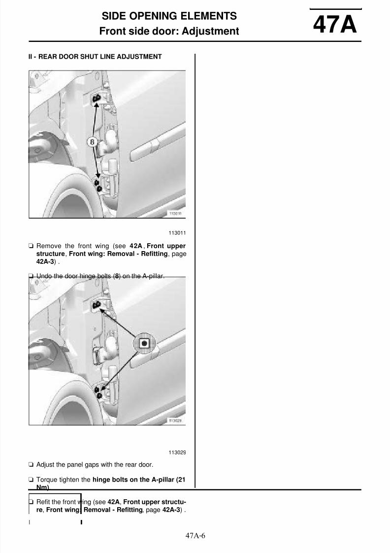
8/21/2019 Panelwork 2009+
http://slidepdf.com/reader/full/panelwork-2009 294/31347A-6
SIDE OPENING ELEMENTS
Front side door: Adjustment 47AII - REAR DOOR SHUT LINE ADJUSTMENT
a Remove the front wing (see 42A , Front upperstructure, Front wing: Removal - Refitting, page42A-3) .
a Undo the door hinge bolts (8) on the A-pillar.
a Adjust the panel gaps with the rear door.
a Torque tighten the hinge bolts on the A-pillar (21Nm).
a Refit the front wing (see 42A, Front upper structu-re, Front wing: Removal - Refitting, page 42A-3) .
113011
113029

8/21/2019 Panelwork 2009+
http://slidepdf.com/reader/full/panelwork-2009 295/31347A-7
SIDE OPENING ELEMENTS
Front side door: Stripping - Restoring
B85 or C85
47A
The order of the operations described below appliesspecifically to replacing the door.
STRIPPING
a Remove:
- the door trim (see Front side door trim: Removal- Refitting) ,
- (see Door sealing film: Removal - Refitting) ,
- the door mirror (see Door mirror: Removal - Re-fitting) ,
- the glass run channel (see Front side door glassrun channel: Removal - Refitting) ,
- the sliding window (see Sliding window in frontside door: Removal - Refitting) ,
- the window lift mechanism (see Front side doorelectric window mechanism: Removal - Refit-ting) or (see Rear side door manual windowcontrol mechanism: Removal - Refitting) ,
- the exterior handle (see Door exterior handle:Removal - Refitting) ,
- the door lock (see Front side door lock: Removal- Refitting) ,
- the wiring harness,
- the protective panel on the door (see Front sidedoor moulding: Removal - Refitting) ,
- the front door pelvic protector (see Front sidedoor seat base lever: Removal - Refitting) .
REASSEMBLING
a Fit the decorative side strip (see Decorative sidestrips: Removal - Refitting) .
a Refit:
- the front door pelvic protector (see Front sidedoor seat base lever: Removal - Refitting) .
- the wiring harness,
- the door lock (see Front side door lock: Removal- Refitting) ,
- the exterior handle (see Door exterior handle:Removal - Refitting) ,
- the window lift mechanism (see Front side doorelectric window mechanism: Removal - Refit-ting) or (see Rear side door manual windowcontrol mechanism: Removal - Refitting) ,
- the sliding window (see Sliding window in frontside door: Removal - Refitting) ,
- the glass run channel (see Front side door glassrun channel: Removal - Refitting) ,
- the door mirror (see Door mirror: Removal - Re-fitting) ,
- the sealing film (see Door sealing film: Removal -Refitting) ,
- the door trim (see Front side door trim: Removal- Refitting) ,
- the protective panel on the door (see Front sidedoor moulding: Removal - Refitting) ,
Note:It is possible to carry out the stripping operations onthe vehicle before removing the door.
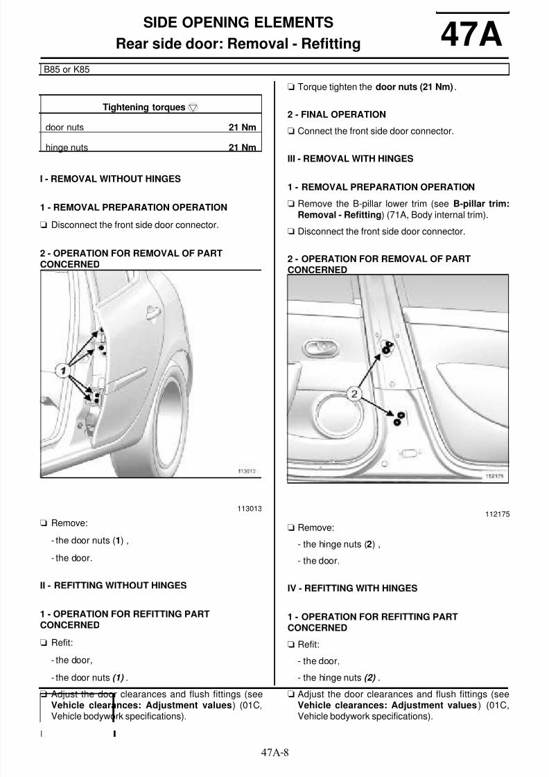
8/21/2019 Panelwork 2009+
http://slidepdf.com/reader/full/panelwork-2009 296/31347A-8
SIDE OPENING ELEMENTS
Rear side door: Removal - Refitting
B85 or K85
47A
I - REMOVAL WITHOUT HINGES
1 - REMOVAL PREPARATION OPERATION
a Disconnect the front side door connector.
2 - OPERATION FOR REMOVAL OF PARTCONCERNED
a Remove:
- the door nuts (1) ,- the door.
II - REFITTING WITHOUT HINGES
1 - OPERATION FOR REFITTING PARTCONCERNED
a Refit:
- the door,
- the door nuts (1) .a Adjust the door clearances and flush fittings (see
Vehicle clearances: Adjustment values) (01C,Vehicle bodywork specifications).
a Torque tighten the door nuts (21 Nm) .
2 - FINAL OPERATION
a
Connect the front side door connector.
III - REMOVAL WITH HINGES
1 - REMOVAL PREPARATION OPERATION
a Remove the B-pillar lower trim (see B-pillar trim:Removal - Refitting) (71A, Body internal trim).
a Disconnect the front side door connector.
2 - OPERATION FOR REMOVAL OF PART
CONCERNED
a Remove:
- the hinge nuts (2) ,
- the door.
IV - REFITTING WITH HINGES
1 - OPERATION FOR REFITTING PARTCONCERNED
a Refit:
- the door,
- the hinge nuts (2) .a Adjust the door clearances and flush fittings (see
Vehicle clearances: Adjustment values) (01C,Vehicle bodywork specifications).
Tightening torquesm
door nuts 21 Nm
hinge nuts 21 Nm
113013112175

8/21/2019 Panelwork 2009+
http://slidepdf.com/reader/full/panelwork-2009 297/31347A-9
SIDE OPENING ELEMENTS
Rear side door: Removal - Refitting
B85 or K85
47A
a Torque tighten the hinge nuts (21 Nm).
2 - FINAL OPERATION
a
Connect the front side door connector.a Refit the B-pillar lower trim (see B-pillar trim: Re-
moval - Refitting) (71A, Body internal trim).

8/21/2019 Panelwork 2009+
http://slidepdf.com/reader/full/panelwork-2009 298/31347A-10
SIDE OPENING ELEMENTS
Rear side door: Adjustment
B85 or K85
47A
ADJUSTMENT VALUES
a For information on the rear side door adjustment va-lues (see Vehicle clearances: Adjustment values)(01C, Vehicle bodywork specifications).
ADJUSTMENT
a There are two options for adjusting the door:
- by means of the mountings on the door box section
(opening clearance adjustment),
- by means of the mountings on the B-pillar (shut lineadjustment): this operation requires the removal ofthe B-pillar interior trim.
a Observe the adjustment sequence.
a
Tightening torquesm
guide pins on the door
box section
13 Nm
indexing bolt on thedoor box section
13 Nm
hinge nuts on the doorbox section
21 N.m
hinge nuts on the B-pillar
21 Nm
112087
109496
Symbols A, B, C and D show the adjustmentoptions.
The black dot in the centre represents the bodyof the bolt.
The grey section represents the component to beadjusted.
The white section represents the adjustmentarea.

8/21/2019 Panelwork 2009+
http://slidepdf.com/reader/full/panelwork-2009 299/31347A-11
SIDE OPENING ELEMENTS
Rear side door: Adjustment
B85 or K85
47A
I - ADJUSTMENT OF OPENING CLEARANCE WITHTHE FRONT DOOR AND THE REAR WING
a Remove the door box section nuts (3) .
a Undo the guide pins and the indexing bolt (4) .
a Adjust the door shut lines.
a Tighten to torque:
- the guide pins on the door box section (13 Nm),
- the indexing bolt on the door box section (13Nm).
a Refit the door box section nuts (3) .
a Torque tighten the hinge nuts on the door boxsection (21 N.m).
113013
113030

8/21/2019 Panelwork 2009+
http://slidepdf.com/reader/full/panelwork-2009 300/31347A-12
SIDE OPENING ELEMENTS
Rear side door: Adjustment
B85 or K85
47A
II - ADJUSTMENT OF SHUT LINES WITH THEFRONT DOOR AND THE REAR WING
a Remove the B-pillar lower trim (see B-pillar trim:Removal - Refitting) (71A, Body internal trim).
a Undo the hinge nuts (5) on the B-pillar.
a Adjust the door shut lines.
a Torque tighten the hinge nuts on the B-pillar (21Nm).
a Refit the B-pillar lower trim (see B-pillar trim: Re-moval - Refitting) (71A, Body internal trim).
112175
113033
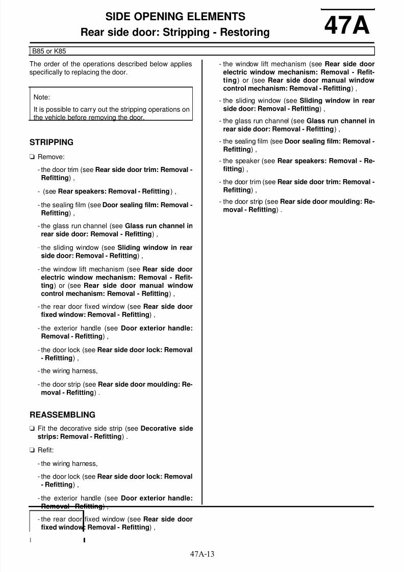
8/21/2019 Panelwork 2009+
http://slidepdf.com/reader/full/panelwork-2009 301/31347A-13
SIDE OPENING ELEMENTS
Rear side door: Stripping - Restoring
B85 or K85
47A
The order of the operations described below appliesspecifically to replacing the door.
STRIPPING
a Remove:
- the door trim (see Rear side door trim: Removal -Refitting) ,
- (see Rear speakers: Removal - Refitting) ,
- the sealing film (see Door sealing film: Removal -Refitting) ,
- the glass run channel (see Glass run channel inrear side door: Removal - Refitting) ,
- the sliding window (see Sliding window in rearside door: Removal - Refitting) ,
- the window lift mechanism (see Rear side doorelectric window mechanism: Removal - Refit-ting) or (see Rear side door manual windowcontrol mechanism: Removal - Refitting) ,
- the rear door fixed window (see Rear side doorfixed window: Removal - Refitting) ,
- the exterior handle (see Door exterior handle:Removal - Refitting) ,
- the door lock (see Rear side door lock: Removal- Refitting) ,
- the wiring harness,
- the door strip (see Rear side door moulding: Re-moval - Refitting) .
REASSEMBLING
a Fit the decorative side strip (see Decorative sidestrips: Removal - Refitting) .
a Refit:
- the wiring harness,
- the door lock (see Rear side door lock: Removal- Refitting) ,
- the exterior handle (see Door exterior handle:Removal - Refitting) ,
- the rear door fixed window (see Rear side doorfixed window: Removal - Refitting) ,
- the window lift mechanism (see Rear side doorelectric window mechanism: Removal - Refit-ting) or (see Rear side door manual windowcontrol mechanism: Removal - Refitting) ,
- the sliding window (see Sliding window in rearside door: Removal - Refitting) ,
- the glass run channel (see Glass run channel inrear side door: Removal - Refitting) ,
- the sealing film (see Door sealing film: Removal -Refitting) ,
- the speaker (see Rear speakers: Removal - Re-fitting) ,
- the door trim (see Rear side door trim: Removal -Refitting) ,
- the door strip (see Rear side door moulding: Re-moval - Refitting) .
Note:It is possible to carry out the stripping operations onthe vehicle before removing the door.

8/21/2019 Panelwork 2009+
http://slidepdf.com/reader/full/panelwork-2009 302/31347A-14
SIDE OPENING ELEMENTS
Fuel filler flap cover: Removal - Refitting 47AREMOVAL
OPERATION FOR REMOVAL OF PARTCONCERNED
a Unclip the fuel filler flap from its mounting.
REFITTING
REFITTING OPERATION FOR PART CONCERNED
a Clip the fuel filler flap cover onto its mounting.
112856
112856

8/21/2019 Panelwork 2009+
http://slidepdf.com/reader/full/panelwork-2009 303/31348A-1
NON-SIDE OPENING ELEMENTS
Bonnet: Removal - Refitting 48A
I - REMOVAL BY MEANS OF THE BONNET BOLTS
1 - REMOVAL PREPARATION OPERATION
a Remove the bonnet soundproofing (see Bonnetsoundproofing: Removal - Refitting) .
a Remove the bonnet jet supply pipe (1) .
2 - OPERATION FOR REMOVAL OF PARTCONCERNED
a Remove:
- the bonnet mounting bolts (2) ,
- the bonnet.
II - REFITTING BY MEANS OF THE BONNET BOLTS
1 - OPERATION FOR REFITTING PARTCONCERNED
a Refit:
- the bonnet,
- the bonnet mounting bolts (2) .
a Adjust the opening clearances and flush fitting (see48A, Non-side opening elements, Bonnet: Ad-justment, page 48A-3) .
a Torque tighten the bonnet mounting bolts (8 Nm).
2 - FINAL OPERATION
a Refit:
- the bonnet jet supply pipe (1) ,
- the bonnet soundproofing (see Bonnet sound-proofing: Removal - Refitting) .
Tightening torquesm
bonnet mounting bolts 8 Nm
bonnet hinge mountingbolts
8 Nm
112036
112032
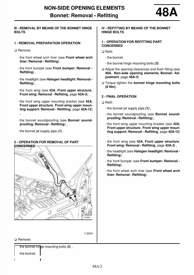
8/21/2019 Panelwork 2009+
http://slidepdf.com/reader/full/panelwork-2009 304/31348A-2
NON-SIDE OPENING ELEMENTS
Bonnet: Removal - Refitting 48AIII - REMOVAL BY MEANS OF THE BONNET HINGEBOLTS
1 - REMOVAL PREPARATION OPERATION
a Remove:
- the front wheel arch liner (see Front wheel archliner: Removal - Refitting) ,
- the front bumper (see Front bumper: Removal -Refitting) ,
- the headlight (see Halogen headlight: Removal -Refitting) ,
- the front wing (see 42A , Front upper structure,Front wing: Removal - Refitting, page 42A-3) ,
- the front wing upper mounting bracket (see 42A,Front upper structure, Front wing upper moun-ting support: Removal - Refitting, page 42A-12),
- the bonnet soundproofing (see Bonnet sound-proofing: Removal - Refitting) ,
- the bonnet jet supply pipe (1) .
2 - OPERATION FOR REMOVAL OF PARTCONCERNED
aRemove:
- the bonnet hinge mounting bolts (3) ,
- the bonnet.
IV - REFITTING BY MEANS OF THE BONNETHINGE BOLTS
1 - OPERATION FOR REFITTING PARTCONCERNED
a Refit:
- the bonnet,
- the bonnet hinge mounting bolts (3) .
a Adjust the opening clearances and flush fitting (see48A, Non-side opening elements, Bonnet: Ad-justment, page 48A-3) .
a Torque tighten the bonnet hinge mounting bolts(8 Nm).
2 - FINAL OPERATION
a Refit:
- the bonnet jet supply pipe (1) ,
- the bonnet soundproofing (see Bonnet sound-proofing: Removal - Refitting) ,
- the front wing upper mounting bracket (see 42A,Front upper structure, Front wing upper moun-ting support: Removal - Refitting, page 42A-12),
- the front wing (see 42A , Front upper structure,
Front wing: Removal - Refitting, page 42A-3) ,
- the headlight (see Halogen headlight: Removal -Refitting) ,
- the front bumper (see Front bumper: Removal -Refitting) ,
- the front wheel arch liner (see Front wheel archliner: Removal - Refitting) .
112034

8/21/2019 Panelwork 2009+
http://slidepdf.com/reader/full/panelwork-2009 305/31348A-3
NON-SIDE OPENING ELEMENTS
Bonnet: Adjustment 48A
ADJUSTMENT VALUES
a For all information about bonnet adjustment values(see Vehicle clearances: Adjustment values) .
ADJUSTMENTa There are two options for adjusting the bonnet:
- by means of the bonnet mounting bolts,
- by means of the bonnet hinge mounting bolts: thisoperation requires the removal of the front wingand the front wing upper mounting bracket.
The bonnet striker must be adjusted in addition tothe bonnet adjustment.
a Observe the adjustment sequence.
a Symbols A, B, C and D show the adjustment op-
tions.
The black dot in the centre represents the body ofthe bolt.
The grey section represents the component to beadjusted.
The white section represents the adjustment area.
Tightening torquesm
bonnet mounting bolts 8 Nm
bonnet hinge mountingbolts
8 Nm
bonnet striker mountingbolts
8 Nm
112091
109496

8/21/2019 Panelwork 2009+
http://slidepdf.com/reader/full/panelwork-2009 306/31348A-4
NON-SIDE OPENING ELEMENTS
Bonnet: Adjustment 48AI - ADJUSTMENT BY MEANS OF THE BONNETMOUNTING BOLTS
a Undo the bonnet mounting bolts (4) .
a Adjust the bonnet panel gaps.
a Torque tighten the bonnet mounting bolts (8 Nm).
II - ADJUSTMENT BY MEANS OF THE BONNETHINGE MOUNTING BOLTS
a Remove:
- the front wing (see 42A , Front upper structure,
Front wing: Removal - Refitting, page 42A-3) ,
- the front wing upper mounting support (see 42A,Front upper structure, Front wing upper moun-ting support: Removal - Refitting, page 42A-12),
a Undo the bonnet hinge mounting bolts (5) .
a Refit:
- the front wing upper mounting support,
- the front wing.
a
Adjust the bonnet panel gaps.a Remove:
- the front wing,
- the front wing mounting bracket.
a Torque tighten the bonnet hinge mounting bolts(8 Nm).
a Refit:
- the front wing upper mounting bracket (see 42A,Front upper structure, Front wing: Removal -Refitting, page 42A-3) ,
- the front wing (see 42A , Front upper structure,Front wing upper mounting support: Removal -Refitting, page 42A-12) .
112035

8/21/2019 Panelwork 2009+
http://slidepdf.com/reader/full/panelwork-2009 307/31348A-5
NON-SIDE OPENING ELEMENTS
Bonnet: Adjustment 48AIII - BONNET STRIKER ADJUSTMENT
a
a Remove:
- the bonnet striker mounting bolts (6) ,
- the bonnet striker.
a Fill in the paintwork.
a Refit the striker and the mounting bolts (6) .
a Adjust the bonnet striker with the bonnet lock.
a Torque tighten the bonnet striker mounting bolts(8 Nm).
113031
Note:
When adjusting the bonnet striker, it is imperativeto remove the striker plate and fill in the pain-twork to protect the bonnet from corrosion.

8/21/2019 Panelwork 2009+
http://slidepdf.com/reader/full/panelwork-2009 308/31348A-6
NON-SIDE OPENING ELEMENTS
Tailgate: Removal - Refitting 48A
I - REMOVAL WITHOUT THE HINGES
1 - REMOVAL PREPARATION OPERATION
a Remove the tailgate trim (see Tailgate lining: Re-moval - Refitting) .
a Disconnect the electrical connectors from:
- the rear screen wiper motor,
- the tailgate lock,
- the heated rear screen.
a Remove:
- the tailgate electrical supply harness,
- the tailgate washer jet tube,
- the tailgate gas struts.
2 - OPERATION FOR REMOVAL OF PARTCONCERNED
a Remove:
- the tailgate mounting bolts (1) ,
- the tailgate.
II - REFITTING WITHOUT HINGES
1 - OPERATION FOR REFITTING PARTCONCERNED
a Refit:
- the tailgate,
- the tailgate mounting bolts (1) .
a Torque tighten the tailgate mounting bolts (10Nm).
2 - FINAL OPERATION
a Refit:
- the tailgate gas struts,
- the tailgate washer jet tube,
- the tailgate electrical supply harness,
a Connect the electrical connectors to:
- the heated rear screen,
- the tailgate lock,
- the rear screen wiper motor,
a Refit the tailgate trim (see Tailgate lining: Removal- Refitting) .
III - REMOVAL WITH HINGES
1 - REMOVAL PREPARATION OPERATION
a Remove the headlining (see Headlining: Removal -Refitting) .
a Disconnect the tailgate electrical supply harness.
a Remove:
- the tailgate washer jet tube,
- the tailgate gas struts.
Tightening torquesm
tailgate mounting bolts 10 Nm
hinge mounting nuts 21 Nm
112177
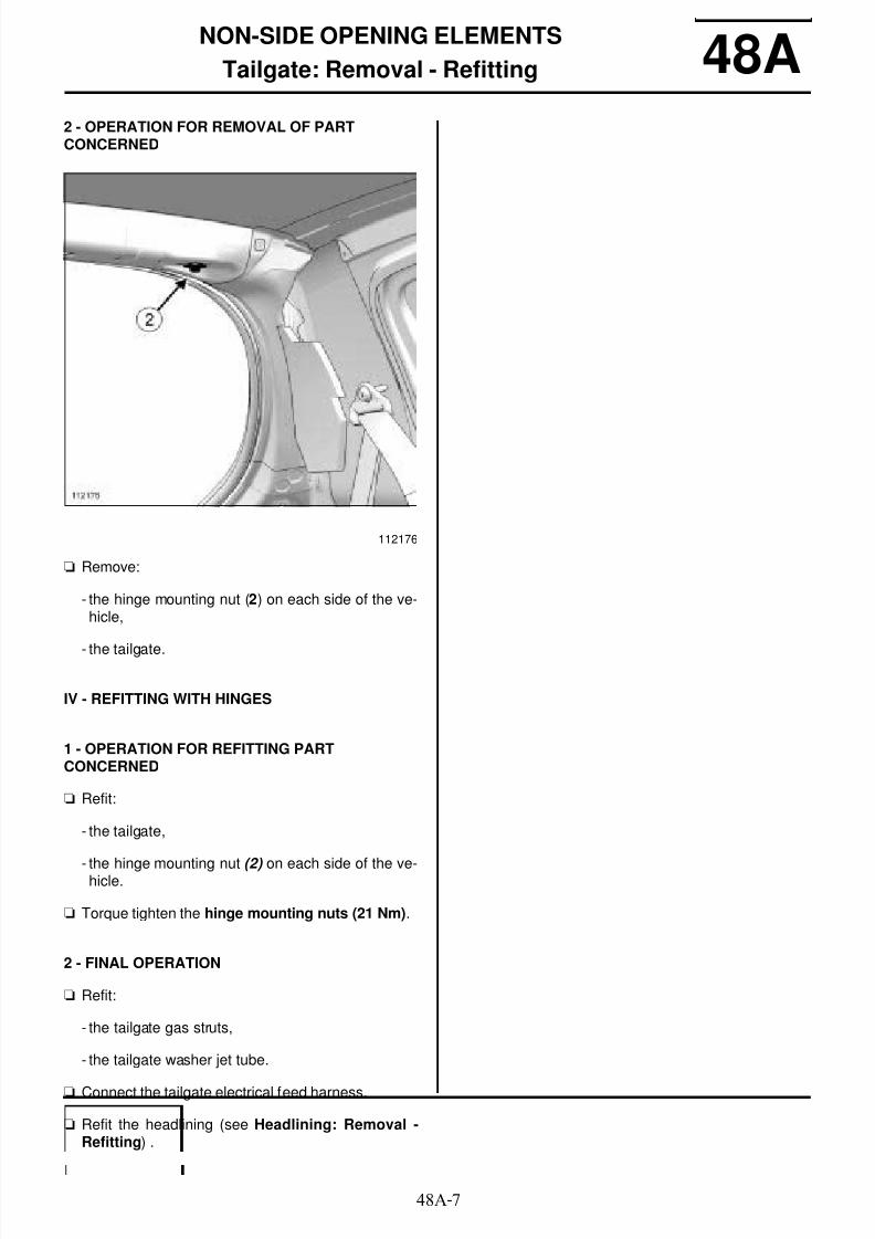
8/21/2019 Panelwork 2009+
http://slidepdf.com/reader/full/panelwork-2009 309/31348A-7
NON-SIDE OPENING ELEMENTS
Tailgate: Removal - Refitting 48A2 - OPERATION FOR REMOVAL OF PARTCONCERNED
a Remove:
- the hinge mounting nut (2) on each side of the ve-hicle,
- the tailgate.
IV - REFITTING WITH HINGES
1 - OPERATION FOR REFITTING PARTCONCERNED
a Refit:
- the tailgate,
- the hinge mounting nut (2) on each side of the ve-hicle.
a Torque tighten the hinge mounting nuts (21 Nm).
2 - FINAL OPERATION
a Refit:
- the tailgate gas struts,
- the tailgate washer jet tube.
a Connect the tailgate electrical feed harness.
a Refit the headlining (see Headlining: Removal -Refitting) .
112176
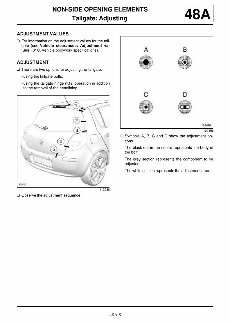
8/21/2019 Panelwork 2009+
http://slidepdf.com/reader/full/panelwork-2009 310/31348A-8
NON-SIDE OPENING ELEMENTS
Tailgate: Adjusting 48AADJUSTMENT VALUES
a For information on the adjustment values for the tail-gate (see Vehicle clearances: Adjustment va-lues) (01C, Vehicle bodywork specifications).
ADJUSTMENT
a There are two options for adjusting the tailgate:
- using the tailgate bolts,
- using the tailgate hinge nuts: operation in additionto the removal of the headlining.
a Observe the adjustment sequence.
a Symbols A, B, C and D show the adjustment op-
tions.
The black dot in the centre represents the body ofthe bolt.
The grey section represents the component to beadjusted.
The white section represents the adjustment area.
112088
109496

8/21/2019 Panelwork 2009+
http://slidepdf.com/reader/full/panelwork-2009 311/31348A-9
NON-SIDE OPENING ELEMENTS
Tailgate: Adjusting 48AI - ADJUSTMENT BY MEANS OF THE TAILGATEMOUNTING BOLTS
a Undo the bolts (6) on each side of the vehicle.
a Adjust the tailgate panel gaps.
a Tighten the bolts (6) .
a Undo the bolts (6) on each side of the vehicle.
a Adjust the tailgate panel gaps.
a Tighten the bolts (6) .
II - ADJUSTMENT BY MEANS OF THE HINGEMOUNTING NUTS
a Remove the headlining (see Headlining: Removal -Refitting) (71A, Body internal trim).
B85 or C85 or S85
113035
K85
126754

8/21/2019 Panelwork 2009+
http://slidepdf.com/reader/full/panelwork-2009 312/31348A-10
NON-SIDE OPENING ELEMENTS
Tailgate: Adjusting 48A
a Undo the nut (7) on each side of the vehicle.
a Adjust the tailgate panel gaps.
a Tighten the bolts (7) .
a Refit the headlining (see Headlining: Removal -Refitting) (71A, Body internal trim).
113034
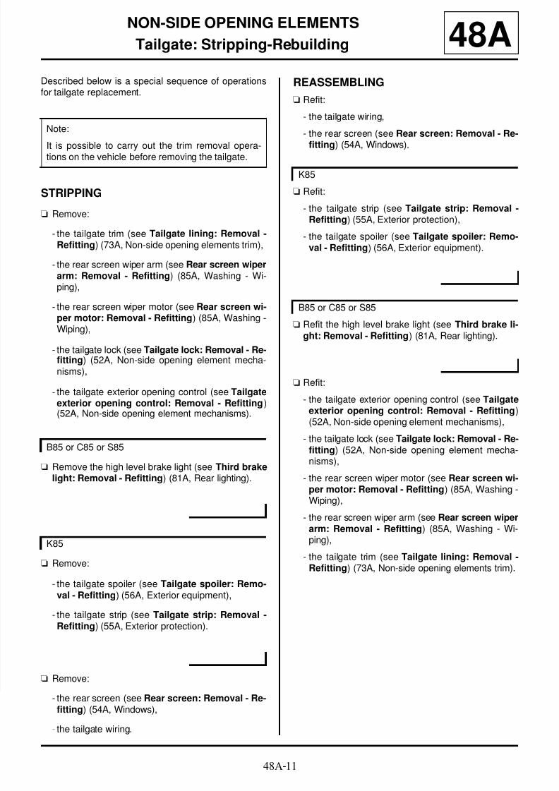
8/21/2019 Panelwork 2009+
http://slidepdf.com/reader/full/panelwork-2009 313/313
NON SIDE OPENING ELEMENTS8A