pam3012 in this lecture digital image processing for ... · digital image processing for...
TRANSCRIPT

1/12/2009
1
PAM3012PAM3012Digital Image Processing for Digital Image Processing for
RadiographersRadiographers
Analog to Digital ConversionAnalog to Digital Conversion
In this lectureIn this lecture
Analog & Digital SignalsAnalog & Digital SignalsAnalog to Digital Conversion (ADC)Analog to Digital Conversion (ADC)
llSamplingSamplingLimitations Limitations
Analog & Digital SignalsAnalog & Digital Signals
Continuous functionContinuous function V of V of continuouscontinuous variable t (time, variable t (time, space etc) : V(t).space etc) : V(t).
Analog
Discrete functionDiscrete function VVkk of of discretediscrete sampling variable sampling variable ttkk, with k = integer: V, with k = integer: Vk = k = V(tV(tkk).).
Digital
-0.2
-0.1
0
0.1
0.2
0.3
0 2 4 6 8 10time [ms]
Volta
ge [V
]
-0.2
-0.1
0
0.1
0.2
0.3
0 2 4 6 8 10sampling time, tk [ms]
Volta
ge [V
]
Analog and Digital SignalsAnalog and Digital Signals
•• ContinuousContinuous
nten
sity
•• Discrete Discrete Distance
In
Distance
Inte
nsit
y
Digital SignalsDigital Signals
•• BinaryBinary–– Base two number Base two number
systemsystem
2277 2266 2255 2244 2233 2222 2211 2200 decimaldecimal
00 00 00 00 00 00 00 00 0000 00 00 00 00 00 00 11 11
00 00 00 00 00 00 11 00 22
•• Binary Integer Binary Integer –– BITS BITS –– ON or OFFON or OFF
•• 8 bit bytes8 bit bytes
00 00 00 00 00 00 11 00 22
00 00 00 00 00 00 11 11 33
..
..
..
..
..
..
..
..
..
..
..
..
..
..
..
..
..
..
..
..
..
..
..
..
..
..
..11 11 11 11 11 11 11 11 255255
Signals in Medical ImagingSignals in Medical Imaging
•• Computer Radiography: Computer Radiography: –– Voltage proportional to light intensityVoltage proportional to light intensity
•• Direct Digital Radiography: Direct Digital Radiography: –– Voltage proportional to XVoltage proportional to X--ray intensityray intensityVoltage proportional to XVoltage proportional to X ray intensityray intensity
•• Computed Tomography: Computed Tomography: –– Voltage proportional to XVoltage proportional to X--ray intensityray intensity
•• Ultrasound: Ultrasound: –– Voltage proportional to US intensityVoltage proportional to US intensity
Analog or Digital?Analog or Digital?

1/12/2009
2
Advantages of Digital Signal• High noise immunity• Adjustable precision• Ease of design (automation) and
F b i ti th f l t• Fabrication, therefore, low cost• Better Reliability• Less need for calibration and maintenance• Ease of diagnosis and repair• Easy to duplicate similar circuits• Easily controllable by computer
Disadvantages of Digital Signals
• Lower speed• Needs converters to communicate with
real world, therefore more expensive , f m pand less precision– Digital to Analog (D/A)– Analog to Digital (A/D)
Analog to Digital ConverterAnalog to Digital Converter
ADCADC
e
Digital SignalDigital SignalContinuous SignalContinuous Signal
SamplingSampling
timeVolt
age SamplingSampling
•• Sample signal intensity at Sample signal intensity at discrete intervalsdiscrete intervals
•• Signal intensity binned into Signal intensity binned into discrete levelsdiscrete levels
•• Number of levels governed by Number of levels governed by number of bits number of bits
Analog to Digital ConversionAnalog to Digital Conversion
Continuous functionContinuous function V of continuouscontinuous variable t (time, space etc) : V(t).
Analog
Discrete functionDiscrete function Vk of discretediscrete sampling variable tk, with k = integer: Vk = V(tk).
Digital
-0.2
-0.1
0
0.1
0.2
0.3
0 2 4 6 8 10sampling time, tk [ms]
Volta
ge [V
]
ts
-0.2
-0.1
0
0.1
0.2
0.3
0 2 4 6 8 10sampling time, tk [ms]
Volta
ge [V
]
ts-0.2
-0.1
0
0.1
0.2
0.3
0 2 4 6 8 10time [ms]
Volta
ge [V
]
Uniform (periodic) sampling. Sampling frequency fS = 1/ tS
-0.2
-0.1
0
0.1
0.2
0.3
0 2 4 6 8 10sampling time, tk [ms]
Volta
ge [V
]
ts
Example: Computed RadiographyExample: Computed RadiographyAnalog to Digital ConverterAnalog to Digital Converter
Digital Signal:Digital Signal:22NN discrete levelsdiscrete levels(where N = number of Bits)(where N = number of Bits)
Analog Signal:Analog Signal:Voltage varying continuously Voltage varying continuously e.g. e.g. --5 to 5 volts5 to 5 volts
timeNum
ber
timeVolt
age
timeNum
ber
timeNum
ber
N

1/12/2009
3
Quantisation ErrorQuantisation Error
•• Digital Accuracy Digital Accuracy depends upon depends upon number of bits of number of bits of ADC.ADC. ta
ge
Max Error
•• Maximum ErrorMaximum Error–– Analog signal amplitude Analog signal amplitude
range, Arange, A–– Digital increment size, NDigital increment size, N–– Number of bits, nNumber of bits, n–– Maximum quantisation error Maximum quantisation error
is equal to half the voltage is equal to half the voltage of the least significant bitof the least significant bit
timeVolt
1max 22 +==
n
ANAq
Quantisation ErrorQuantisation Error
•• Digital Accuracy Digital Accuracy depends upon depends upon number of bits of number of bits of ADCADC ta
ge
Max Error
ADC.ADC.
•• Average ErrorAverage Error–– Average error is equal to Average error is equal to
half the maximum errorhalf the maximum error
timeVolt
2max 2421
+===
nav
ANAqq
Dynamic RangeDynamic Range
•• Range of values in each pixel Range of values in each pixel graygray--scale range scale range , , dynamic range or Bitdynamic range or Bit--depthdepth
•• Numerical range in each pixelNumerical range in each pixelNumerical range in each pixelNumerical range in each pixel•• Visually: number of shades of gray that can Visually: number of shades of gray that can
be representedbe represented•• Number of levels = 2Number of levels = 2nn
–– Where n = number of bitsWhere n = number of bits
Dynamic RangeDynamic Range•• 88--BitsBits2288 --> 256 shades> 256 shades
255255
00
77
•• 33--BitsBits2233 --> 8 shades> 8 shades
•• 11--BitsBits2211 --> 2 shades> 2 shades
00
0011
ExampleExample
An analog signal of amplitude 12v is An analog signal of amplitude 12v is sampled with a 8sampled with a 8--bit ADC.bit ADC.Calculate the maximum & average Calculate the maximum & average m m m & gm m m & gquantisation noise quantisation noise
Analog to Digital ConverterAnalog to Digital Converter
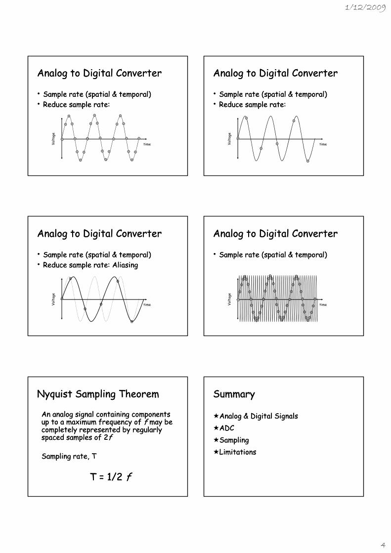
•• Sample rate (spatial & temporal)Sample rate (spatial & temporal)
timeVolt
age
1/12/2009
4
Analog to Digital ConverterAnalog to Digital Converter
•• Sample rate (spatial & temporal)Sample rate (spatial & temporal)•• Reduce sample rate:Reduce sample rate:
timeVolt
age
Analog to Digital ConverterAnalog to Digital Converter
•• Sample rate (spatial & temporal)Sample rate (spatial & temporal)•• Reduce sample rate:Reduce sample rate:
timeVolt
age
Analog to Digital ConverterAnalog to Digital Converter
•• Sample rate (spatial & temporal)Sample rate (spatial & temporal)•• Reduce sample rate: Aliasing Reduce sample rate: Aliasing
timeVolt
age
Analog to Digital ConverterAnalog to Digital Converter
•• Sample rate (spatial & temporal)Sample rate (spatial & temporal)
timeVolt
age
Nyquist Sampling TheoremNyquist Sampling Theorem
An analog signal containing components An analog signal containing components up to a maximum frequency of up to a maximum frequency of ff may be may be completely represented by regularly completely represented by regularly spaced samples of 2spaced samples of 2ffspaced samples of 2spaced samples of 2ff
Sampling rate, TSampling rate, T
T = 1/2 T = 1/2 ff
SummarySummary
Analog & Digital SignalsAnalog & Digital SignalsADCADCSamplingSamplingLimitationsLimitations