palletech system - cottrill & co · 2019-05-13 · yamazaki mazak corporation 1-131 takeda,...
TRANSCRIPT

Specifications are subject to change without notice.This product is subject to all applicable export controllaws and regulations.The accuracy data and other data presented in thiscatalogue were obtained under specific conditions.They may not be duplicated under different conditions. (room temperature, workpiece materials, tool material,cutting conditions, etc.) E
Palletech System
PALLETECH SYSTEM 14.09.1000 F 99J512812E1
Pa
llete
ch
Sy
ste
mwww.mazak.com
YAMAZAKI MAZAK CORPORATION1-131 Takeda, Oguchi-cho, Niwa-gun, Aichi-pref., Japan
TEL : +(81)587-95-1131 FAX : +(81)587-95-2717

02 03
Manufacturing innovation to meet yourrequirements today as well as tomorrowThe PALLETECH SYSTEM is designed with the flexibility required for
shorter product life cycles, reduced in-process inventory, just-in-time
production and other demands of today’s manufacturing environment.
We offer the PALLETECH MANUFACTURING CELL (1 level) and PALLETECH
HIGH RISE SYSTEM (2, 3 levels) according to your volume of production and
budget. Furthermore, the PALLETECH SYSTEM is designed for convenient
system expansion after the initial installation to easily respond to increased
production requirements in the future.
High-productivity unmanned system
PALLETECH SYSTEM
Enhanced Productivity
PALLETECH HIGH RISE SYSTEM - 3 levels stocker with 18 pallets, 1 loading station, 1 machining center

Number ofoperators/Manned time
Unmannedoperation (Hrs/Day)
Production rate(Parts/Day)
InvestmentRatio
Number of required machines
Main specifications
60-tool magazine,Monitoring system B,Scale feedback system,Chip conveyor
120-tool magazine,Monitoring system B,Scale feedback system,Chip conveyor
160-tool magazine,Monitoring system B,Scale feedback system,Chip conveyor
Machining center with 2PC
7 1.29 55 2.0 4
Machining center with 6PC
5 1.3 55 6.0 2
PALLETECH HIGH RISE SYSTEM
3 1 55 15.0 1
04 05
Investment ComparisonPOINT1 By using a PALLETECH SYSTEM to its full
capacity, the start-up costs can be minimizedwithout suffering any loss in production.In addition, the payback period is minimized.
Assume 55 workpieces are machined daily each with a one-hour cycle.
System comparison between HORIZONTAL CENTER NEXUS 6800-II with 2PC,HORIZONTAL CENTER NEXUS 6800-II with 6PC, and PALLETECH HIGH RISESYSTEM with HORIZONTAL CENTER NEXUS 6800-II.
POINT2
Investment Requirements Comparison:
Assume the initial investment cost for the PALLETECH HIGH RISE SYSTEM is 1, the cost for both the 2-pallet changer and 6-pallet changer machines are about 30% higher. Accordingly, the PALLETECH SYSTEM has the lowest initial investment.
System comparison (constant production output)
Considerable reduction of required number of operators:
Palletech system
7 machiningcenters with 2PC
5 machiningcenters with 6PC
PALLETECH HIGHRISE SYSTEM with3 machining centers
Number of required operators Labor expense
4
2
1
100%
50%
25%
HORIZONTAL CENTERNEXUS 6800-II with 2PC
Required net machine hours/daily 55 parts x 1 hr. = 55 hrs.
(10 + 2) x 70 % =8.4 hours*10 hrs. includes 2 hrs of overtime
55 hrs. ÷ 8.4 hrs. = 7 machines
55 hrs. ÷ 11.3 hrs. = 5 machines55 hrs. ÷ 19.6 hrs. = 3 machines
(8 + 6) x 81% =11.3 hours
(8 + 15) x 85% =19.6 hours
(Manned operation + unmanned operation)x utilization rate = hours of production
(Manned operation + unmanned operation)x utilization rate = hours of production
(Manned operation + unmanned operation)x utilization rate = hours of production
55 parts x 1 hr. = 55 hrs. 55 parts x 1 hr. = 55 hrs.
Effective machine hours
Required numbero f machines
HORIZONTAL CENTERNEXUS 6800-II with 6PC
PALLETECH HIGH RISE SYSTEMwith HORIZONTAL CENTER
NEXUS 6800-II

Input Data of Production ComparisonMachining cycle
Required number of workpieces
Load/unload time (average)
Annual workdays
Manned shifts (PALLETECH / 6PC / 2 PC)
Unmanned ( PALLETECH / 6PC / 2 PC )
Operation rate (PALLETECH / 6PC / 2 PC)
Sales price of a part
Material cost
Labor (8 hrs. shift/operator)
Overhead
Depreciation period
60 min./part
55/day
5 min./part
5 days/week 50 weeks/year
8 hrs./day 8 hrs./day 10 hrs./day
15 hrs./day 6 hrs./day 2 hrs./day
85% 81% 70%
$110
$10
$55/hour
$50/hour
7 years straight line depreciation
1
0
1.291.3
PAYBACK
1 2 3 4 5 6 7
PALLETECH HIGH RISE SYSTEM6 pallet changer2 pallet changer
YEARS
$
-$
The PALLETECH SYSTEM has the fastest payback period ofjust over two years. The machines with the 6 pallet changer have a payback period of almost three years and the standard machines with 2 pallet changers have a period of four and one half years. This simplified payback calculation clearly shows the most significant benefit of a PALLETECH SYSTEM when compared to other production systems to produce the same quantity of workpieces. The PALLETECH SYSTEM has the lowest required investment along with the lowest operation expenses which results in the fastest payback period.
06 07
Palletech system
POINT3The graph below shows the basicpayback period for the 3 differentsystems used to produce the sameproduction requirements. Payback isdefined as the time to recover theinvestment amount from positivecash flow (contribution to profit orgross margin plus depreciation).Operation data for all systems areshown in the table to the right – thePALLETECH SYSTEM performsunmanned operation 15 hours every day, the machines with the 6 pallet changer system performunmanned operation 6 hours a day and the machines with the 2 pallet changers 2 hours a day. The directlabor charge per hour is the labor expense for each operator and includes all benefits and necessary taxesborne by the employer. The indirect labor is charged for every hour of operation – both manned andunmanned. Depreciation is for a seven year period and is calculated by the straight line method.
An analysis of PALLETECH SYSTEM operationPOINT4
To efficiently use limited factory floor space, the PALLETECH SYSTEM providesthe best solution.
A PALLETECH HIGH RISE SYSTEM when compared with the 2PC and 6PC HORIZONTAL CENTER NEXUS 6800-II is shown below:
HORIZONTAL CENTER NEXUS 6800-II(60-tool magazine, 2PC) x 7 machines
HORIZONTAL CENTER NEXUS 6800-II(120-tool magazine, 6PC) x 5 machines
HORIZONTAL CENTER NEXUS 6800-II[(160-tool magazine, 2PC) x 3 machines] + PALLETECH HIGH RISE SYSTEM (1 loading station, 36 pallets)
Floor Space Requirements Comparison
Floor Space Requirement Ratio
100%
106%
75%
9,40
0 m
m (3
70.0
8”)
6,100 mm(240.16”)42,400 mm (1,669.30”)
11,6
00 m
m (4
56.7
0”)
7,300 mm (287.40”)36,500 mm (1,437.01”)
12,0
00m
m (4
72,4
4”)
24,800mm (976,38”)
Investment Comparison
Floor space requirement: 399 m² (4295 ft²)
Floor space requirement: 424 m² (4564 ft²)
Floor space requirement: 298 m² (3208 ft²)
HORIZONTAL CENTER NEXUS 6800-II(60-tool magazine, 2PC) x 7 machines
HORIZONTAL CENTER NEXUS 6800-II (120-tool magazine, 6PC) x 5 machines
HORIZONTAL CENTER NEXUS 6800-II [(160-tool magazine, 2PC) x 3 machines] + PALLETECH HIGH RISE SYSTEM(1 loading station, 36 pallets)

08 09
The rail for the loader and the chip pan are integrated
with the pallet stocker in order to provide convenient
system expansion. The PALLETECH HIGH RISE
SYSTEM features a 2-level pallet stocker for increased
storage capacity with a minimum floor space
requirement. Either the PALLETECH MANUFACTURING
CELL or PALLETECH HIGH RISE SYSTEM can be
selected according to current production
requirements and budget. Either system can be easily
expanded after the initial installation in response to
increased production requirements.
When a pallet is at the loading
station, the pallet can be
indexed to 4 positions at every
90-degrees for convenient
workpiece loading and
unloading. Additionally, the
loading station is equipped with
a safety door as standard
equipment to maintain a safe
working environment for the
operator. The PALLETECH
SYSTEM can be equipped with
up to a maximum of 8 loading
stations.
PALLETECH SYSTEM specifications
Pallet LoaderPallets are automatically transferred from the pallet stocker to the
loading station and then to a machining center by the pallet loader.
The system controller commands the pallet loader according to the
registered production schedule. The pallet loader features high speed
acceleration and positioning to eliminate non-productive pallet waiting
time. Additionally, the loader utilizes 2 different pallet transferring
speeds – one when a workpiece is on a pallet and the other when no
workpiece is on a pallet.
Pallet Stocker
Loading Station
The e-BOT CELL 720 is designed to realize up to 720 hours of unmanned operation per month in the machining of a wide
variety of workpieces. Even for changes in production lot sizes, labor requirements are minimal.
e-BOT CELL 720
ModulePALLETECH SYSTEM Modules
Palletech system
○: Available-: Not available
□ 400 □ 500 □ 630 □ 800 □ 1000 □ 1250PALLETECH MANUFACTURING CELL ○ ○ ○ ○ ○ ○PALLETECH HIGH RISE SYSTEM (2 levels) ○ ○ ○ ○ PALLETECH HIGH RISE SYSTEM (3 levels) ○ ○ ○HORIZONTAL CENTER NEXUS series 4000-III 5000-III 6800-II 8800-II 10800-II 12800-II 6000-II VARIAXIS series i-500 i-700 i-600 i-800INTEGREX series e-1060V/6II e-1060V/8II e-1550V/10II e-1850V/12II e-1250V/8II e-RAMTEC V/10 i-500V/5 i-630V/6 e-RAMTEC V/8VORTEX series i-630V/6 e-1060V/8

10 11
Palletech system
Ease of OperationPALLETECH MANUFACTURING CELL Web
Program managementProgram transfer
Operation instructions display
Production management (office)
Setup station (factory)
Manufacturing technology (office)
Tool room (factory)
Tool life/breakage monitoring
Operation monitoringScheduling
Different security level settings are available Display of PALLETECH MANUFACTURING CELL WEB
All functions are available over networked PCs without any special software thanks to the browser-based operation system. The system can be managed by pallets number or parts number.
■ Raw material and finished workpieces stored in stocker (Option)
■ Tool resource check simulation (Standard equipment)
Missing-tool list
Unused-tool list
With this software, by using data in the PMC-Web server, tool resource check is simulated, and “Missing-tool list” and “Unused-tool list” are output in a CSV format file every 4 hours (Up to a week in the future)
Convenient functions for efficient operation
Simulation display Output list
Containers with workpiece raw material can be stored in the stocker. Pallets with fixtures are automatically brought to the system loading station for the loading of workpieces according to the production schedule. By linking pallets with the workpiece container, when the pallet is brought to a loading station the container with the required workpiece material is automatically brought to the other loading station. As a result, material management is conveniently realized and minimizes the accumulation of parts in the loading station area.
System monitor screen
Raw material / finished workpiece management
Workpiece station
Loading station
Workpiece pallet

PALLETECH MANUFACTURING CELL Web (PMC-Web) Functions
Operation environment
System
Machine control
Job instructions
Tool management
Simulation
Measurement management
Utilization
Monitoring
Windows browser screen display, Security
Pallet number schedule, 3-level priority setting, Part number schedule (process monitoring function), Automatic pallet allocation, Delivery time/priority number schedule, 2-shift schedule selection, Workpiece preparation schedule, Pre-process priority, Post process priority, Automatic allocation of loading stations, Automatic allocation of machine in operation, Function to assign same machine, First machining stop, Continuous machining function (machine-to-machine), Pallet call function, Pallet hold/urgent designation, Selection of Pallet transport priority
Unit skip function, Simultaneous workpiece set/machining of multiple kinds of workpieces, Automatic machining program transfer, Machining start (Workpiece No. search), Machining program transfer over Ethernet, Automatic transfer of machining sub-program to hard disk operation area, External program automatic transfer, Program directory management, Temporary management of program, Workpiece offset automatic transfer, Automatic power OFF
Machining face or machining process designation, Job instruction at loading station, Link to detailed jobinstruction, Re-machining designation, Urgent designation, Hold designation, Cancel designation
Display of tool life / damaged tool / tool life notice, Automatic process function when tool breakage is detected,Listing of used tools, Tool resource check
Pallet transport simulation
Measurement result data entry at loading station, Selectable for machine workpiece measurement result out oftolerance – pallet remain in machine or transferred to loading station
Machine operation utilization, Loader robot utilization, Loading station utilization, Pallet utilization, Machiningresults, Operation log output
System, Machine, Loader robot, Loading station, Pallet status, Alarm
12 13
Machining Program
MATRIX 2 MATRIX 2 MATRIX 640MPro 640M (WPC method) (Workpiece method) (Z offset method)
MATRIX 2 NEXUS(Machining center) ◎ ̶ ̶ △ △
MATRIX 2 (INTEGREX e-V) ◎ ◎ ̶ △ △
MATRIX (INTEGREX) ̶ ̶ ◎ ̶ ̶
640M Pro ̶ ̶ ̶ ◎ △
640M ̶ ̶ ̶ ̶ ◎
◎: Machining programs can be transferred from PMC-Web to CNC
△: Requires program modification by using Input/Output function of MAZATROL. If MATRIX, M640M Pro and M640M CNCs are in a system, program modification is required for each CNC type. Modified programs must have a different program number.-: Not available
CNC (Machine) type
Note1: Limited compatibility between MAZATROL versions as shown below
Palletech system
PALLETECH MANUFACTURING CELL Web
Program data 9999 Registered main programs
Pallet data 240
Schedule Number of pages 10
data Number of data per page 300 Maximum 100 data per each priority: “Urgent,” “Normal” or “Hold”
Fixture data 9999
Pallet data 9999
Parts data 9999
Schedule data 9999
PALLETECH MANUFACTURING CELL Web Specifications
Max. number of machines 16 Maximum 15 machines when a MAZATROL controller for pallet loader robot is installed
CNC system MAZATROL MATRIX 2 ○ (see Note 1)
MAZATROL MATRIX 2 NEXUS ○ (see Note 1)
MAZATROL 640M ○ (see Note 1)
MAZATROL 640M Pro ○ (see Note 1)
Max. number of loading stations 8
No. of pallet loader robot 1
Max. pallet storage capacity 240
Specification Notes
Data
Pallet number
schedule
Parts number
schedule
System
Machine dimensions
10,0
69 (3
96.4
2")
600
(23.
62")
1,31
0 (5
1.57
")
11,9
78 (4
71.5
7")
5,84
5 (2
30.1
2")
5,80
0 (2
28.3
5") (
3 le
vels
)
5,23
3 (S
afet
y co
ver)
4,05
0 (1
59.4
5") (
2 le
vels
)
2,30
0 (9
0.55
")
(1 le
vel)
3,93
4 (1
54.8
8")
1,000 (39.37")
1,000 (39.37")
11,434 (450.16")
9,434 (371.42")
The pallet numbers are as follows:
Stocker (1 level)・・・No.1~No.6
Stocker (2 levels)・・・No.7~No.12
Stocker (3 levels)・・・No.13~No.18
Unit mm
Loader Robot
PALLETECH MANUFACTURING CELL Loader Robot Specifications
3 levels pallet stocker: 18 pallets, 1 Loading stationHORIZONTAL CENTER NEXUS 6800-II with TOOL HIVE (280 tools)
PALLETECH HIGH RISE SYSTEM Loader Robot Specifications
500 (1102) 850 (1874) 1150 (2535) 1730 (3814) 2700 (5952) 400 (882) 650 (1433) 850 (1874) 1800 (3968) 2700 (5952) 500 (1102) 850 (1874) 1150 (2535) 1730 (3814)
A-axis [m/min (IPM)] 100 (3937) 100 (3937) 80 (3150) 80 (3150) 60 (2362) 100 (3937) 100 (3937) 80 (3150) 80 (3150) 60 (2362) 100 (3937) 100 (3937) 80 (3150) 80 (3150)
B-axis [m/min (IPM)] 60 (2362) 80 (3150) 50 (1969) 40 (1575) 35 (1378) 57 (2244) 57 (2244) 50 (1969) 40 (1575) 35 (1378) 60 (2362) 80 (3150) 50 (1969) 40 (1575)
C-axis [m/min (IPM)] 10 (394) 8 (315) 8 (315) 8 (315) 2 (79) 10 (394) 10 (394) 8 (315) 8 (315) 8 (315) 10 (394) 14 (551) 8 (315) 8 (315)
500 (1102) 850 (1874) 1150 (2535) 1730 (3814) 2700 (5952) 4000 (8818) 7500 (16534) 400 (882) 650 (1433) 850 (1874) 1800 (3968) 2700 (5952) 5000 (11023) 7500 (16534)
A-axis [m/min (IPM)] 120 (4724) 120 (4724) 80 (3150) 80 (3150) 60 (2362) 60 (2362) 40 (1575) 100 (3937) 100 (3937) 80 (3150) 80 (3150) 60 (2362) 60 (2362) 40 (1575)
B-axis [m/min (IPM)] 80 (3150) 80 (3150) 50 (1969) 40 (1575) 35 (1378) 40 (1575) 50 (1969) 57 (2244) 57 (2244) 50 (1969) 40 (1575) 35 (1378) 40 (1575) 50 (1969)
C-axis [m/min (IPM)] 2.5 (98) 2.5 (98) 2.8 (110) 2.8 (110) 8 (315) 1.3 (51) - 3 (118) 3 (118) 2.8 (110) 2.8 (110) 2 (79) 1.3 (51) -
HORIZONTAL HORIZONTAL HORIZONTAL HORIZONTAL HORIZONTAL HORIZONTAL HORIZONTAL VARIAXIS VARIAXIS INTEGREX INTEGREX INTEGREX INTEGREX INTEGREX CENTER CENTER CENTER CENTER CENTER CENTER CENTER i-500 i-700 i-500V/5 e-1060V/6 II e-1060V/8 II e-1550V/10 II e-1850V/12 II NEXUS 4000-III NEXUS 5000-III NEXUS 6000-II NEXUS 6800-II NEXUS 8800-II NEXUS 10800-II NEXUS 12800-II i-600 i-800 i-630V/6 e-1250V/8 II
HORIZONTAL HORIZONTAL HORIZONTAL HORIZONTAL HORIZONTAL VARIAXIS VARIAXIS INTEGREX INTEGREX INTEGREX CENTER CENTER CENTER CENTER CENTER i-500 i-700 i-500V/5 e-1060V/6 II e-1060V/8 II NEXUS 4000-III NEXUS 5000-III NEXUS 6000-II NEXUS 6800-II NEXUS 8800-II i-600 i-800 i-630V/6 e-1250V/8 II
HORIZONTAL HORIZONTAL HORIZONTAL HORIZONTAL CENTER CENTER CENTER CENTER NEXUS 4000-III NEXUS 5000-III NEXUS 6000-II NEXUS 6800-II
2 levels 3 levels
Max. workpiece weight[kg (lbs)]
Max. workpiece weight[kg (lbs)]
14 15
Palletech system
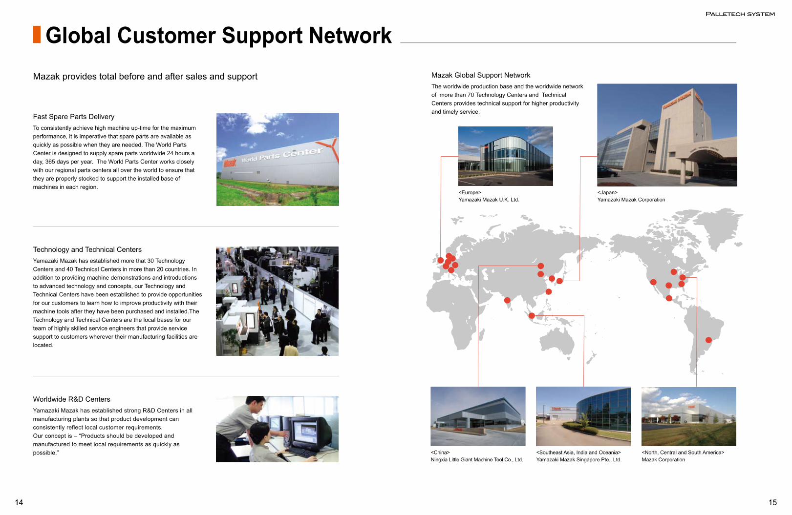
Global Customer Support Network
Fast Spare Parts DeliveryTo consistently achieve high machine up-time for the maximum performance, it is imperative that spare parts are available as quickly as possible when they are needed. The World Parts Center is designed to supply spare parts worldwide 24 hours a day, 365 days per year. The World Parts Center works closely with our regional parts centers all over the world to ensure that they are properly stocked to support the installed base of machines in each region.
Mazak provides total before and after sales and support
Technology and Technical CentersYamazaki Mazak has established more that 30 Technology Centers and 40 Technical Centers in more than 20 countries. In addition to providing machine demonstrations and introductions to advanced technology and concepts, our Technology and Technical Centers have been established to provide opportunities for our customers to learn how to improve productivity with their machine tools after they have been purchased and installed.The Technology and Technical Centers are the local bases for our team of highly skilled service engineers that provide service support to customers wherever their manufacturing facilities are located.
Worldwide R&D CentersYamazaki Mazak has established strong R&D Centers in all manufacturing plants so that product development can consistently reflect local customer requirements. Our concept is – “Products should be developed and manufactured to meet local requirements as quickly as possible.”
Mazak Global Support NetworkThe worldwide production base and the worldwide network of more than 70 Technology Centers and Technical Centers provides technical support for higher productivity and timely service.
<Europe>Yamazaki Mazak U.K. Ltd.
<Japan>Yamazaki Mazak Corporation
<China>Ningxia Little Giant Machine Tool Co., Ltd.
<Southeast Asia, India and Oceania>Yamazaki Mazak Singapore Pte., Ltd.
<North, Central and South America>Mazak Corporation