pajek. pajek is a program, for windows, for analysis and visualization of large networks having...
TRANSCRIPT

Network
Pajek

Introduction
Pajek is a program, for Windows, for analysis and visualization of large networks having some thousands or even millions of vertices. In Slovenian language the word pajek means spider.

Application
Pajek should provide tools for analysis and visualization of such networks:
collaboration networks, organic molecule in chemistry, protein-receptor interaction networks, genealogies, Internet networks, citation networks, diffusion (AIDS, news, innovations) networks, data-mining (2-mode networks), etc.
See also collection of large networks at: http://vlado.fmf.uni-lj.si/pub/networks/data/

Main goals
to support abstraction by (recursive) decomposition of a large network into several smaller networks that can be treated further using more sophisticated methods;
to provide the user with some powerful visualization tools;
to implement a selection of efficient (subquadratic) algorithms for analysis of large networks.
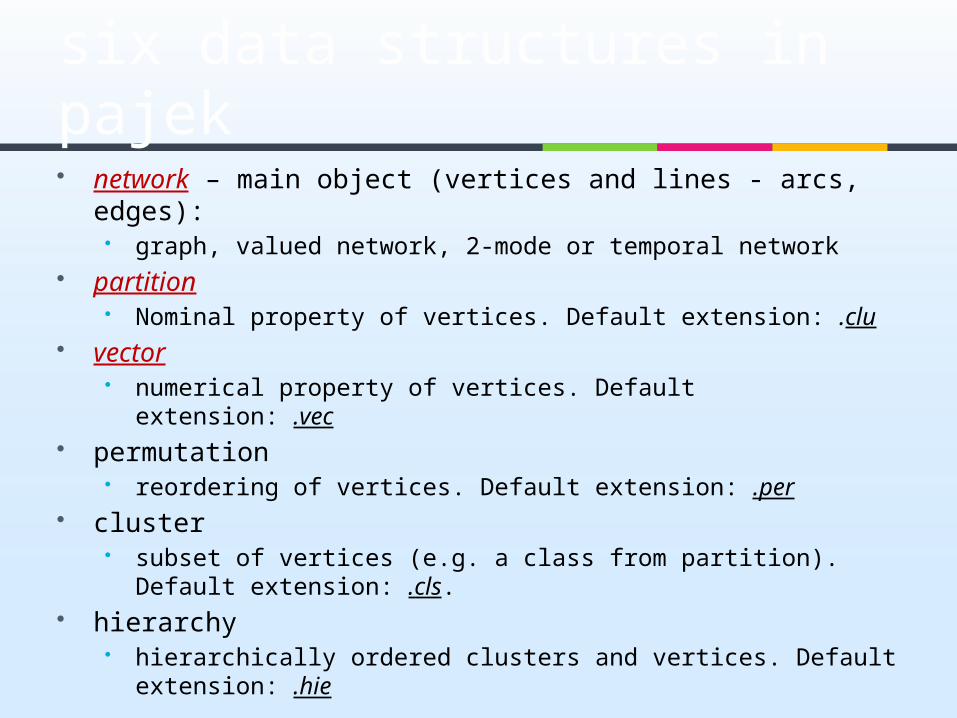
six data structures in pajek network – main object (vertices and lines - arcs, edges):
graph, valued network, 2-mode or temporal network partition
Nominal property of vertices. Default extension: .clu vector
numerical property of vertices. Default extension: .vec permutation
reordering of vertices. Default extension: .per cluster
subset of vertices (e.g. a class from partition). Default extension: .cls.
hierarchy hierarchically ordered clusters and vertices. Default
extension: .hie

Network – .net Network can be defined in different ways on input file. Look at
three of them: 1. List of neighbours (Arcslist / Edgeslist)(see test 1.net)
*Vertices 51 ”a”2 ”b”3 ”c”4 ”d”5 ”e”*Arcslist1 2 42 33 1 44 5*Edgeslist1 5


Explanation Data must be prepared in an input (ASCII) file. Program NotePad
can be used for editing. Much better is a shareware editor, TextPad.
Words, starting with *, must always be written in first column of the line. They indicate the start of a definition of vertices or lines.
Using *Vertices 5 we define a network with 5 vertices. This must always be the first statement in definition of a network.
Definition of vertices follows after that – to each vertex we give a label, which is displayed between “ and ”.
Using *Arcslist, a list of directed lines from selected vertices are declared (1 2 4 means, that there exist two lines from vertex 1, one to vertex 2 and another to vertex 4).
Similarly *Edgeslist, declares list of undirected lines from selected vertex.
In the file no empty lines are allowed – empty line means end of network.

Network – .net 2. Pairs of lines (Arcs / Edges) (see test 2.net)
*Vertices 51 ”a”2 ”b”3 ”c”4 ”d”5 ”e”*Arcs1 2 11 4 12 3 23 1 13 4 24 5 1*Edges1 5 1
Explanation
Directed lines are defined using *Arcs, undirected lines are defined using *Edges. The third number in rows defining arcs/edges gives the value/weight of the arc/edge.
In the previous format (Arcslist / Edgeslist) values of lines are not defined the format is suitable only if all values of lines are 1.
If values of lines are not important the third number can be omitted (all lines get value 1).
In the file no empty lines are allowed – empty line means end of network.

Network – .net
3.Matrix (see test 3.net)*Vertices 51 ”a”2 ”b”3 ”c”4 ”d”5 ”e”*Matrix0 1 0 1 10 0 2 0 01 0 0 2 00 0 0 0 11 0 0 0 0
Explanation
In this format directed lines (arcs) are given in the matrix form (*Matrix). If we want to transform bidirected arcs to edges we can use “Network>create new network>Transform>Arcs to Edges>Bidirected only”

Additional definition of network Additionally, Pajek enables precise definition of
elements used for drawing networks (coordinates of vertices, shapes and colors of vertices and lines, ...).
Example: (see test 4.net)*Vertices 51 “a” box2 “b” ellipse3 “c” diamond4 “d” triangle5 “e” empty...

Layout of networks Energy: The network is presented like a
physical system, and we are searching for the state with minimal energy
Kamada-Kawai: using separate components, you can tile connected components in a plane
Fruchterman-Reingold: draw in a plane or space and selecting the repulsion factor
Eigen Values: Selecting 2 or 3 eigenvectors to become the coordinates of vertices. Can obtain nice pictures
Draw

Partition – .clu
Partitions are used to describe nominal properties of vertices. e.g., 1-men, 2-women
Definition in input file (see test.clu)*Vertices 512221

Vector – .vec
Vectors are used to describe numerical properties of vertices (e.g., centralities).
Definition in input file (see test.vec)*Vertices 50.580.250.250.080.25

Pajek project files
It is time consuming to load objects one by one. Therefore it is convenient to store all data in one file, called Pajek project file (.paj). (see test.paj)
Project files can be produced manually by using “File>Pajek Project File>Save”
To load objects stored in Pajek project file select “File>Pajek Project File>Read”

Menu structure
Commands are put to menu according to the following criterion:
commands that need only a network as input are available in menu Net,
commands that need as input two networks are available in menu Networks,
commands that need as input two objects (e. g., network and partition) are available in menu Operations,
commands that need only a partition as input are available in menu Partition . . .
Global and local views on network

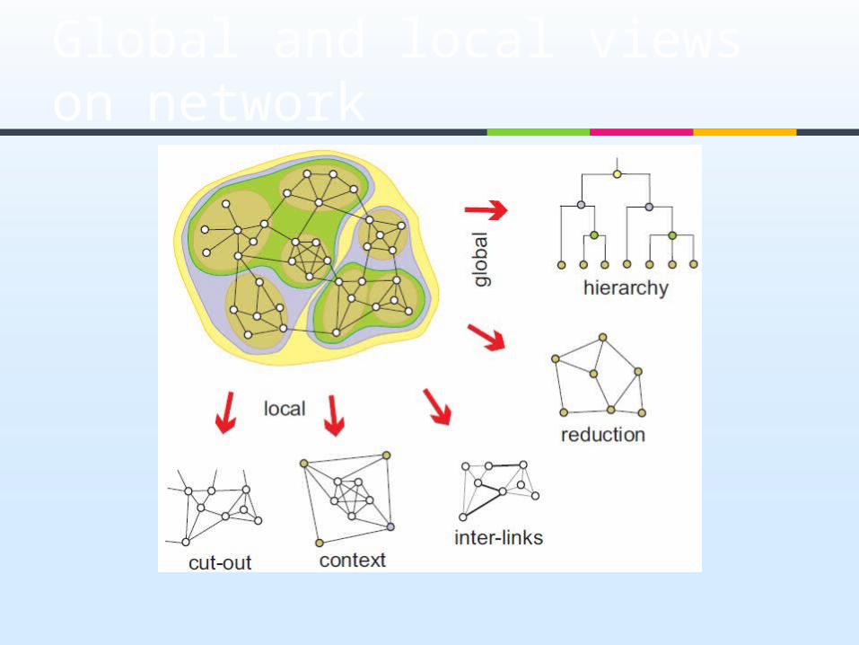
Global and local views on network Local view is obtained by extracting sub-
network induced by selected cluster of vertices.
Global view is obtained by shrinking vertices in the same cluster to new (compound) vertex. In this way relations among clusters of vertices are shown.
Combination of local and global view is contextual view: Relations among clusters of vertices and selected vertices are shown.

Example
Import and export in 1994 among 80 countries are given. They is given in 1000$. (See Country_Imports.net)
Partition according to continents (see Country_Continent.clu) 1 – Africa, 2 – Asia, 3 – Europe, 4 – N.
America, 5 – Oceania, 6 – S. America.Operations>Extract from Network>Partition Operations>Shrink
Network>Partition

Operations>Extract from Network>Partition
Extracting Subnetwork

Operations>Shrink Network>Partition
Extracting Subnetwork
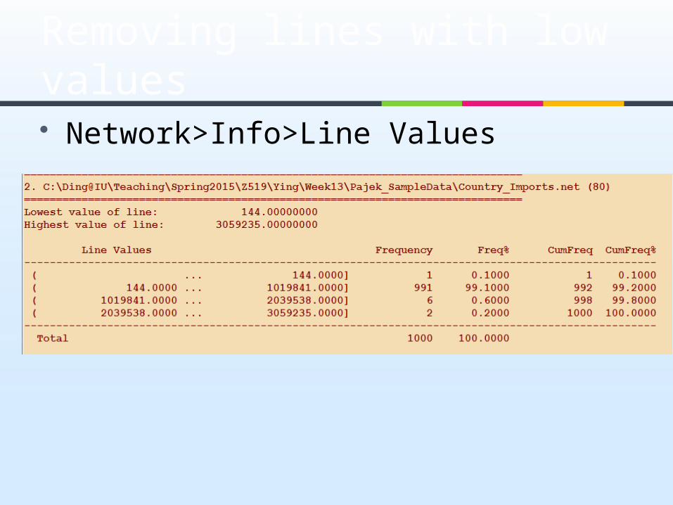
Network>Info>Line Values
Removing lines with low values
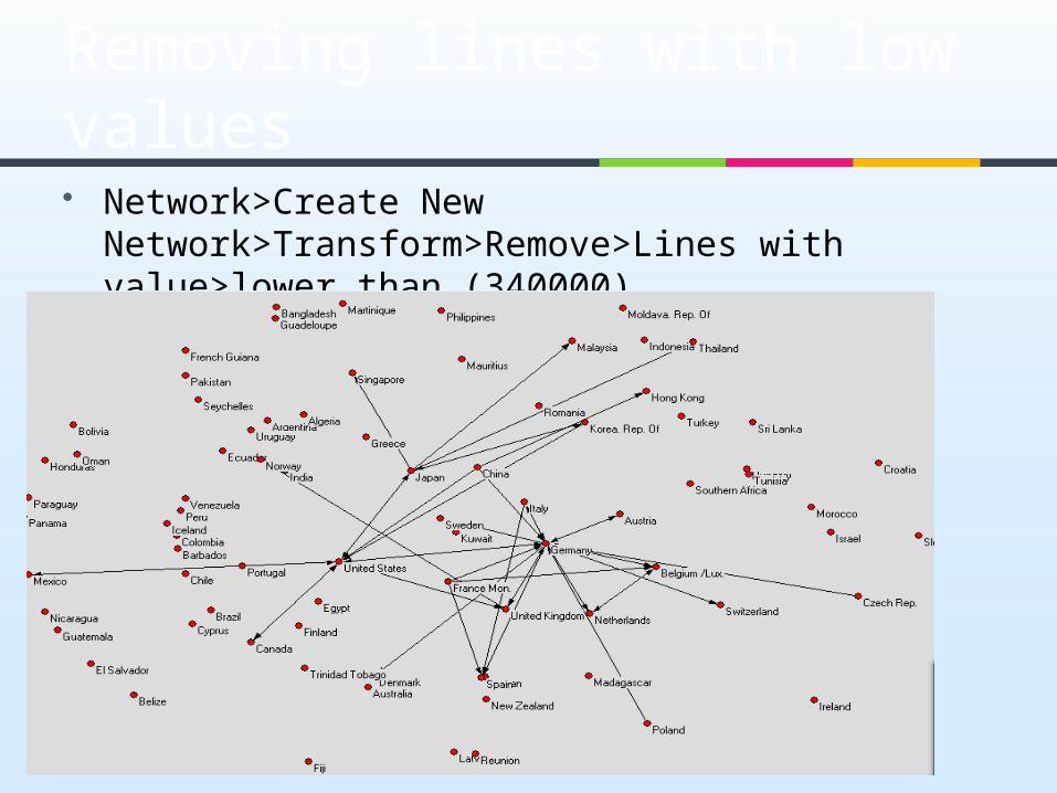
Network>Create New Network>Transform>Remove>Lines with value>lower than (340000)
Removing lines with low values
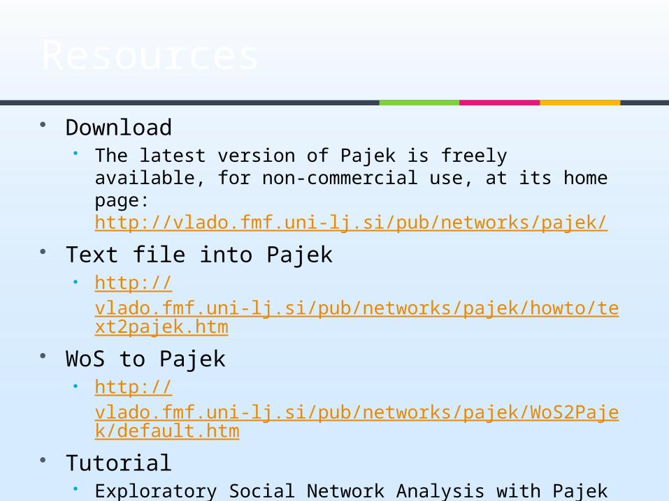
Resources
Download The latest version of Pajek is freely available, for non-
commercial use, at its home page: http://vlado.fmf.uni-lj.si/pub/networks/pajek/
Text file into Pajek http://
vlado.fmf.uni-lj.si/pub/networks/pajek/howto/text2pajek.htm
WoS to Pajek http://
vlado.fmf.uni-lj.si/pub/networks/pajek/WoS2Pajek/default.htm
Tutorial Exploratory Social Network Analysis with Pajek
visit Pajek wiki for more information http://pajek.imfm.si/doku.php

WOS TO PAJEK
http://pajek.imfm.si/doku.php?id=wos2pajek/

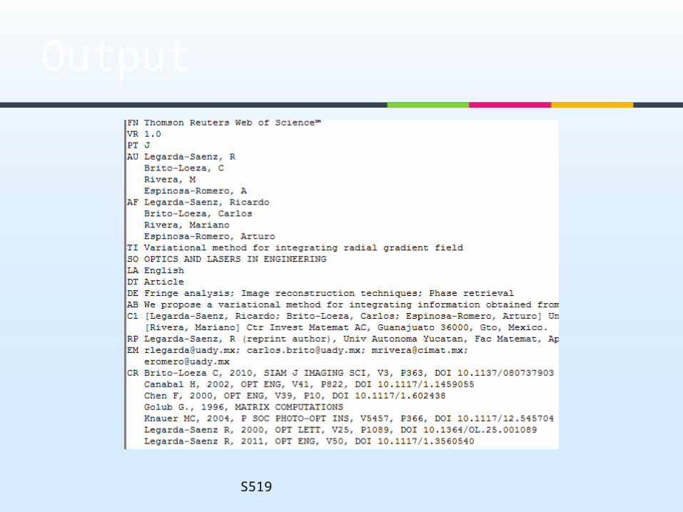
Web of Science
S519

Output
S519
Output
S519

The download link: http
://pajek.imfm.si/doku.php?id=wos2pajek The new tutorial slides:
http://pajek.imfm.si/lib/exe/fetch.php?media=faq:wos:wos2pajek07.pdf
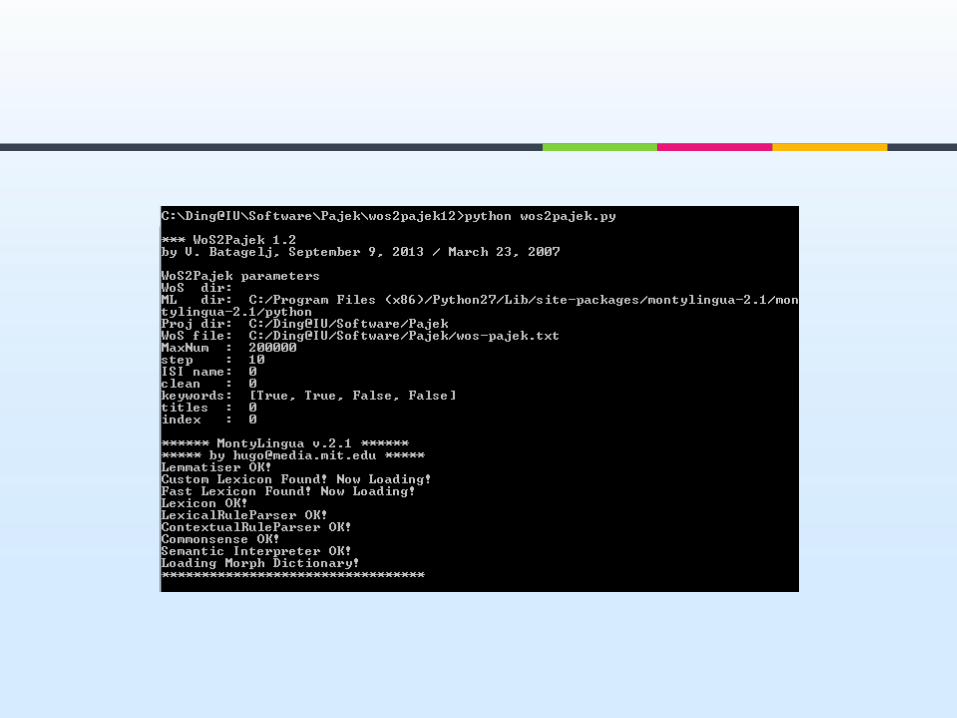
wos2pajek

Download from: http://web.media.mit.edu/~hugo/montylingua/
Unpack it and copy ‘montylingua-2.1’ to C:\Python26\Lib\site-packages
Set up a new environment variable named ‘MONTYLINGUA’ and set the variable value as c:\Python26\Lib\site-packages\MontyLingua-2.1\Python
MontyLingua

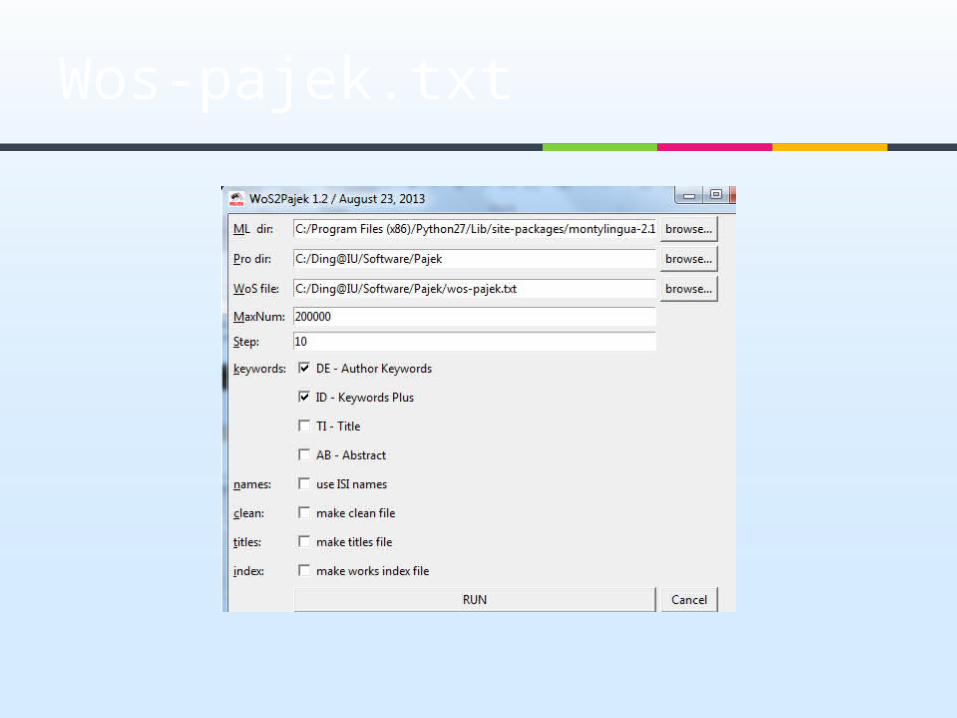
Download the latest version of WoS2Pajek. http
://pajek.imfm.si/doku.php?id=wos2pajek Unpack it, and double click on
WoS2Pajek.py to show the main interface of program:
wos2pajek


You can also put all wos files in a folder
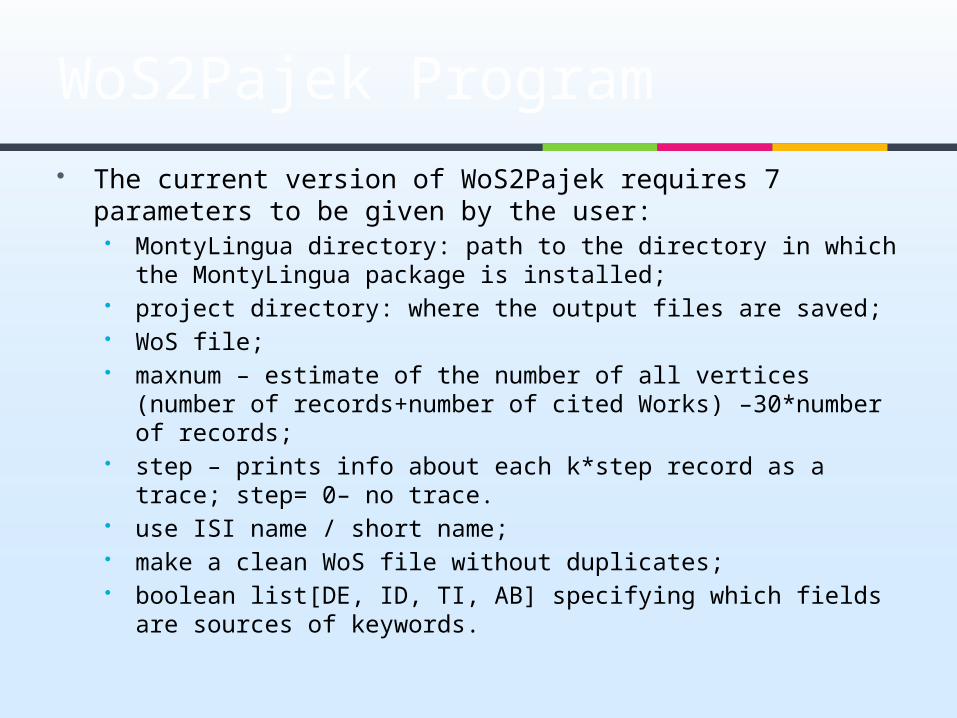
The current version of WoS2Pajek requires 7 parameters to be given by the user:
MontyLingua directory: path to the directory in which the MontyLingua package is installed;
project directory: where the output files are saved; WoS file; maxnum – estimate of the number of all vertices (number of
records+number of cited Works) –30*number of records; step – prints info about each k*step record as a trace; step= 0–
no trace. use ISI name / short name; make a clean WoS file without duplicates; boolean list[DE, ID, TI, AB] specifying which fields are sources
of keywords.
WoS2Pajek Program
Wos-pajek.txt
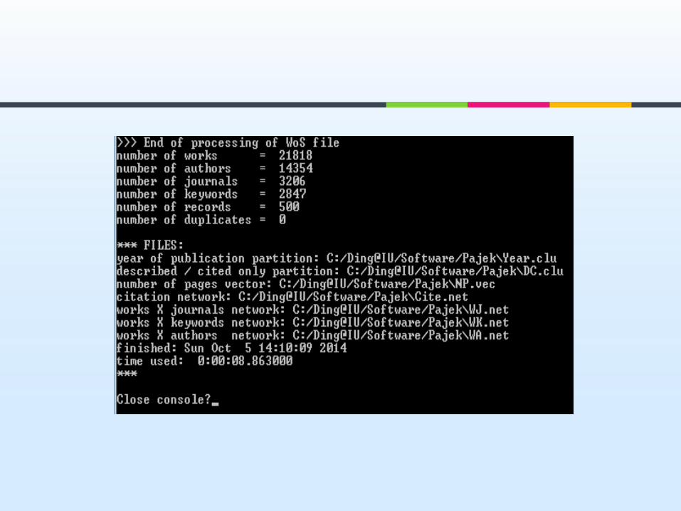

Network/Info/General Network/Create New
Network/Transform/Remove/Loops Network/Create New
Network/Transform/Remove/Multiple lines/Single line
Cite.net

Paper citation network
Questions What are highly cited
articles? The diameter of the
network? What are the major
clusters? More questions?
CiteNew.net

Network/Create Partition/Components/Strong [2] Operations/Network+Partition/Extract
SubNetwork [1-*] Operations/Network+Partition/Transform/Remove
Lines/Between Cluster
Save citestrong.clu
Strong component of cite network

Read WA.net Network/2-mode network/2-mode to
1-mode/Columns Network/Create Partition/Components/Weak [2] Operations/Network+Partition/Extract
SubNetwork[1-*] Network/Create New
Network/Transform/Remove/Loops
WANew.net (which is a co-author network)
Questions: The author with highest co-authors?
Co-author network

[Read Cite.net] Network/Create New Network/Transform/1-mode
to 2-mode Network/2-mode Network/2-mode to
1-mode/Rows Network/Create Partition/Components/Weak [2] Operations/Network + Partition/Extract
SubNetwork [1-*]
Bibliographic coupling network

[Read Cite.net] Network/Create Partitions/Degree/Output Operations/Network+Partition/Extract subNetwork
[1-*] Network/Create New Network/Transform/1-mode
to 2-mode Network/2-mode network/2-mode to
1-mode/Columns Network/Create Partition/Components/Weak [2] Operations/Network+Partition/Extract
SubNetwork [1-*]
Co-citation network

NETWORK ANALYSIS

Two-mode network
One-mode network each vertex can be related to each other
vertex. Two-mode network
vertices are divided into two sets and vertices can only be related to vertices in the other set.
Example
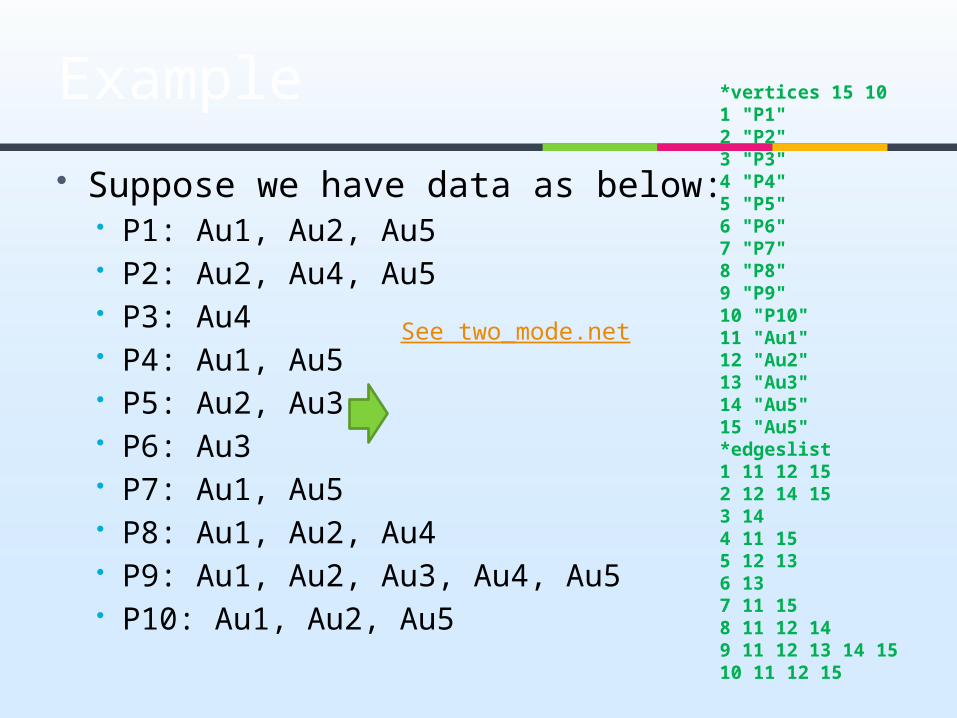
Suppose we have data as below: P1: Au1, Au2, Au5 P2: Au2, Au4, Au5 P3: Au4 P4: Au1, Au5 P5: Au2, Au3 P6: Au3 P7: Au1, Au5 P8: Au1, Au2, Au4 P9: Au1, Au2, Au3, Au4, Au5 P10: Au1, Au2, Au5
*vertices 15 101 "P1"2 "P2"3 "P3"4 "P4"5 "P5"6 "P6"7 "P7"8 "P8"9 "P9"10 "P10"11 "Au1"12 "Au2"13 "Au3"14 "Au5"15 "Au5"*edgeslist1 11 12 152 12 14 153 144 11 155 12 136 137 11 158 11 12 149 11 12 13 14 1510 11 12 15
See two_mode.net

Transforming to valued networks
The network is transformed into an ordinary network, where the vertices are elements from the first subset, using
“Network>2 mode network>2-Mode to 1-Mode>Rows”.
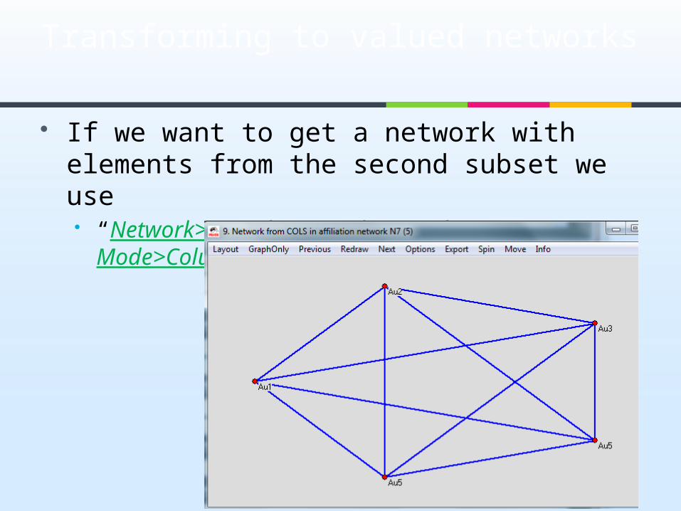
Transforming to valued networks
If we want to get a network with elements from the second subset we use “Network>2 mode network>2-Mode to 1-
Mode>Columns”.
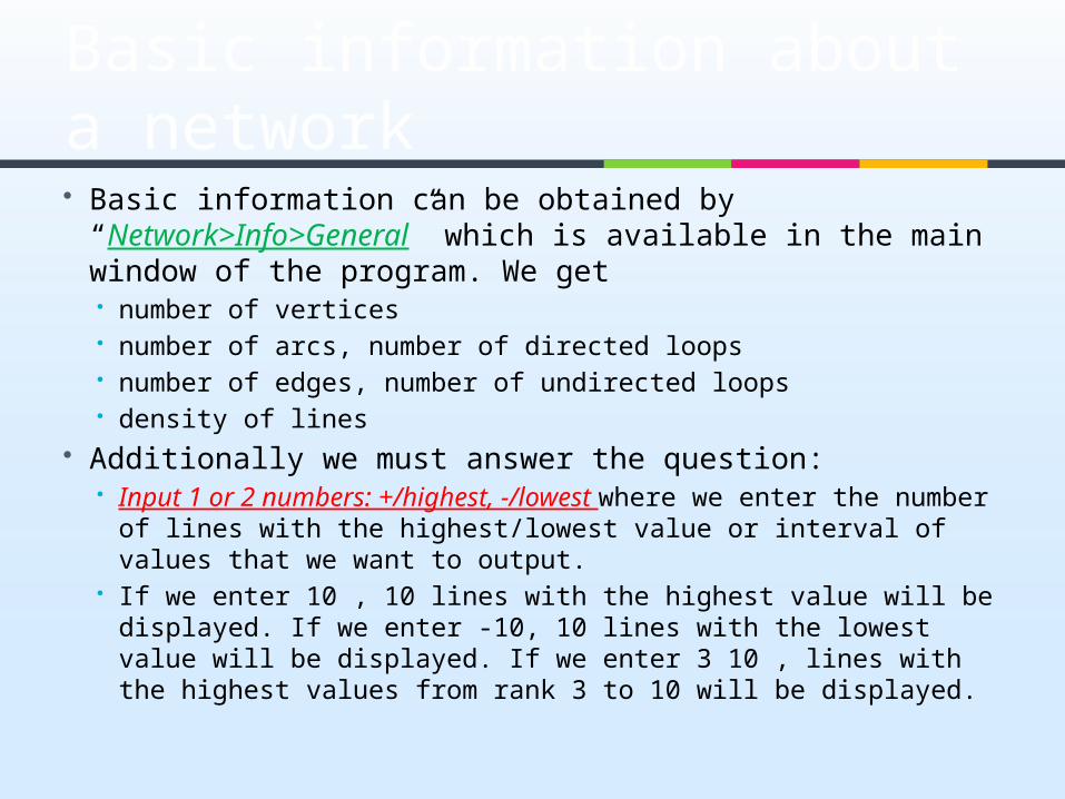
Basic information about a network Basic information can be obtained by
“Network>Info>General” which is available in the main window of the program. We get
number of vertices number of arcs, number of directed loops number of edges, number of undirected loops density of lines
Additionally we must answer the question: Input 1 or 2 numbers: +/highest, -/lowest where we enter the
number of lines with the highest/lowest value or interval of values that we want to output.
If we enter 10 , 10 lines with the highest value will be displayed. If we enter -10, 10 lines with the lowest value will be displayed. If we enter 3 10 , lines with the highest values from rank 3 to 10 will be displayed.
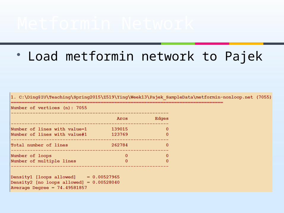
Load metformin network to Pajek
Metformin Network

EntityMetrics
Ding, Y., Song, M., Han, J., Yu, Q., Yan, E., Lin, L., & Chambers, T. (2013). Entitymetrics: Measuring the impact of entities. PLoS One, 8(8): 1-14.
Entitymetrics is defined as using entities (i.e., evaluative entities or knowledge entities) in the measurement of impact, knowledge usage, and knowledge transfer, to facilitate knowledge discovery.

EntityMetrics

Network/Create New Network/SubNetwork with Paths/Info on Diameter
Pajek returns only the two vertices that are the furthest away.
Diameter of the network

Component
Strongly connected components Network>Create
Partition>Components>Strong Weakly connected components
Network>Create Partition>Components>Weak
Result is represented by a partition vertices that belong to the same
component have the same number in the partition.
Example component.net
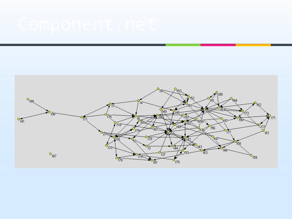
Component.net

Go to partition weak component, Partition>make network>random
network>Input Visualize the new random network
Weak Component

Weak Component
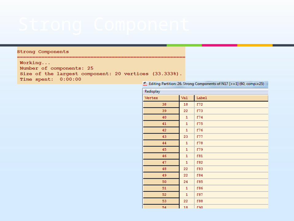
Strong Component
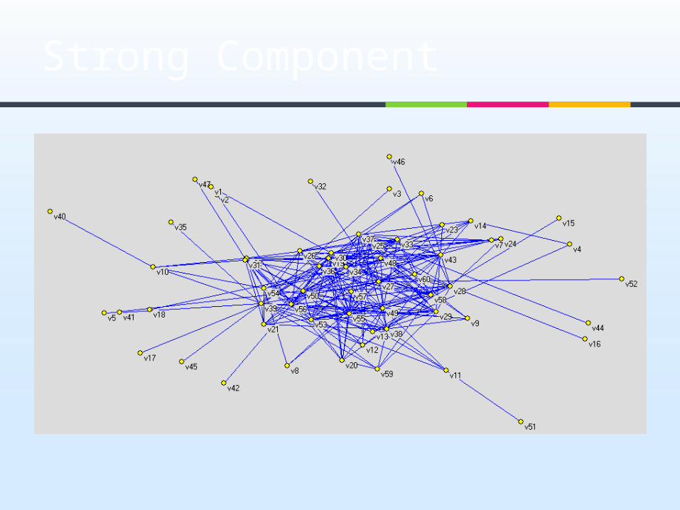
Strong Component

A cut-vertex is a vertex whose deletion increases the number of components in the network.
A bi-component is a component of minimum size 3 that does not contain a cut-vertex.
Bicomponent

Bicomponent example
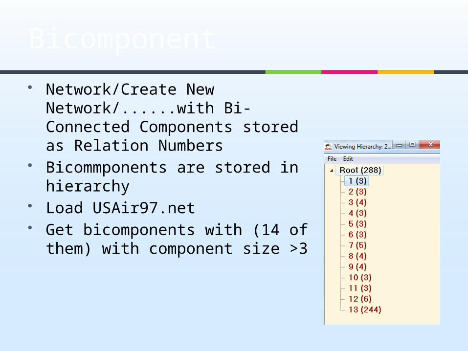
Network/Create New Network/......with Bi-Connected Components stored as Relation Numbers
Bicommponents are stored in hierarchy
Load USAir97.net Get bicomponents with (14 of
them) with component size >3
Bicomponent
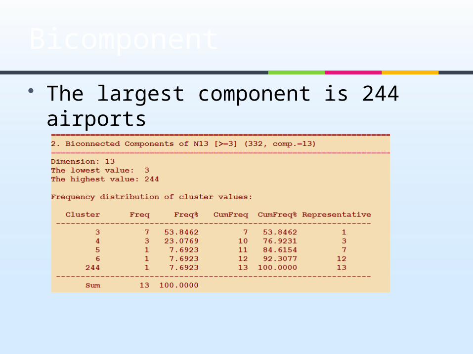
The largest component is 244 airports
Bicomponent
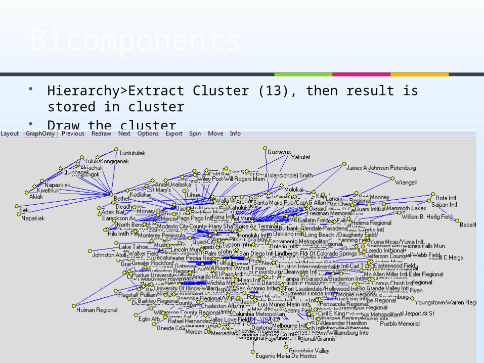
Hierarchy>Extract Cluster (13), then result is stored in cluster
Draw the cluster
Bicomponents
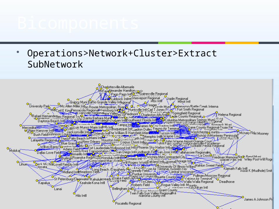
Operations>Network+Cluster>Extract SubNetwork
Bicomponents
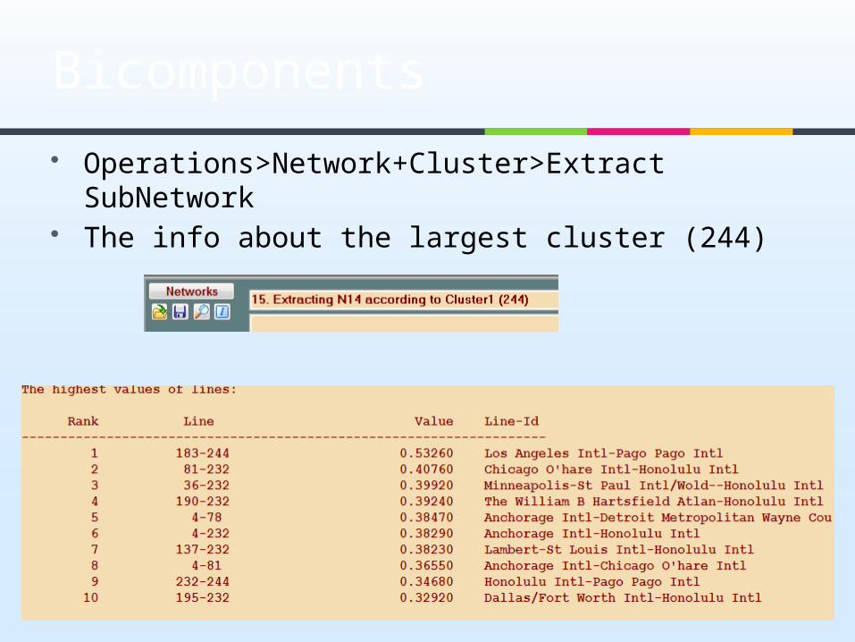
Operations>Network+Cluster>Extract SubNetwork
The info about the largest cluster (244)
Bicomponents

Network>Create Partition>Degree>Input
Busy airports
Bicomponents
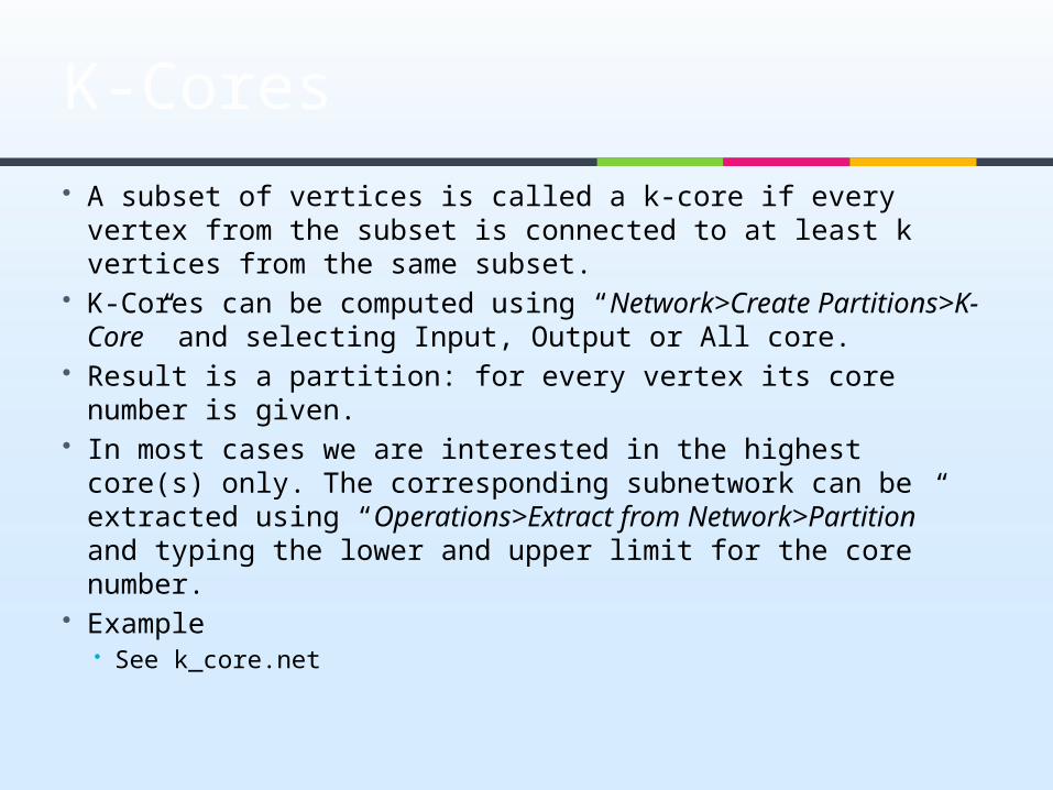
K-Cores A subset of vertices is called a k-core if every vertex from
the subset is connected to at least k vertices from the same subset.
K-Cores can be computed using “Network>Create Partitions>K-Core” and selecting Input, Output or All core.
Result is a partition: for every vertex its core number is given.
In most cases we are interested in the highest core(s) only. The corresponding subnetwork can be extracted using “Operations>Extract from Network>Partition” and typing the lower and upper limit for the core number.
Example See k_core.net
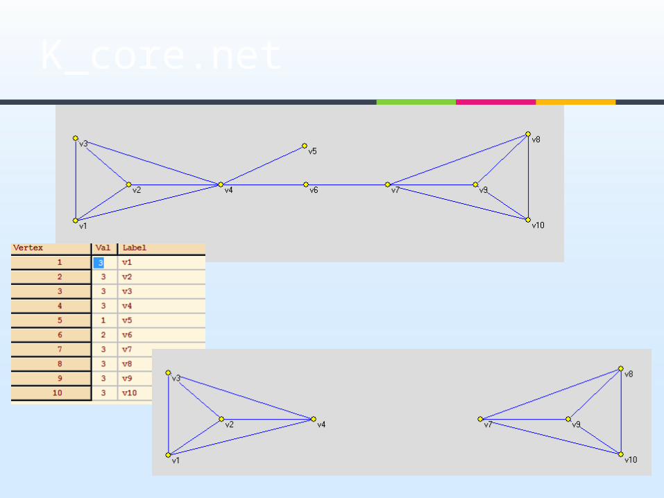
K_core.net

Clustering Coefficients
How three nodes are connected Calculation of local Clustering
Coefficients: Network>Create Vector>Clustering
Coefficients>CC1 K_core.net

Degree Centrality
Degree centrality Network>Create Partition>Degree, or Network/Create Vector/Centrality/Degree;
Example: Metformin network
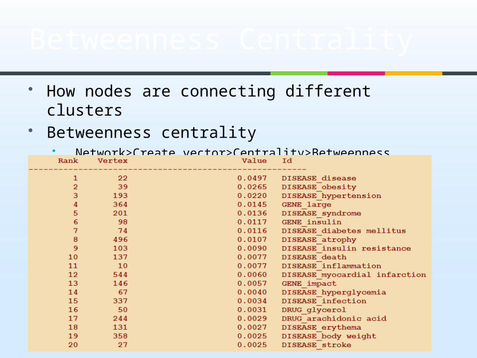
How nodes are connecting different clusters Betweenness centrality
Network>Create vector>Centrality>Betweenness
Betweenness Centrality

The betweenness centrality value for each node
Betweenness Centrality
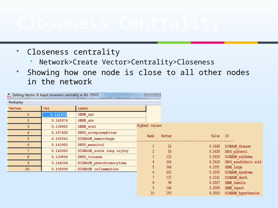
Closeness centrality Network>Create Vector>Centrality>Closeness
Showing how one node is close to all other nodes in the network
Closeness Centrality

Network/Create New Network/SubNetwork with Paths/.. ...One Shortest Path between Two Vertices
Enter two vertices Forget values on lines
Yes, if searching for the shortest path is based on lengths
No, if searching for the shortest path is based o vlaue of lines
Identify vertices in source network No
Result will be a new subnetwork containing the two selected vertices
Layout>Energy>Kamada Kawai>Fix first and last
Shortest Path

Network/Create New Network/SubNetwork with Paths/.. ...One Shortest Path between Two Vertices (17-7045)
Shortest path