pages from phaser_3100mfpservicemanual3
DESCRIPTION
Xerox Phaser 3100 3/3TRANSCRIPT
7/17/2019 Pages From Phaser_3100MFPServiceManual3
http://slidepdf.com/reader/full/pages-from-phaser3100mfpservicemanual3 1/44
General Procedures and Information
6-52 04/08 Phaser 3100 MFP
GP 16 Packing and Transport ing the MachineIf you need to transport the machine, always use the original package. If the machine is not prop-erly packed, the warranty may be cancelled. Also check that the machine new location meets theinstallation requirements, GP 9.
1. Set the machine On/Off switch to Off (position 0).
2. Disconnect all the cables connected to the machine.
3. Remove the document feeder and gently push the paper tray inwards to avoid obstructing themachine packaging.
4. Pack the machine in its original plastic wrapping and put it in its original packing box togetherwith the other components (power cord, etc.).
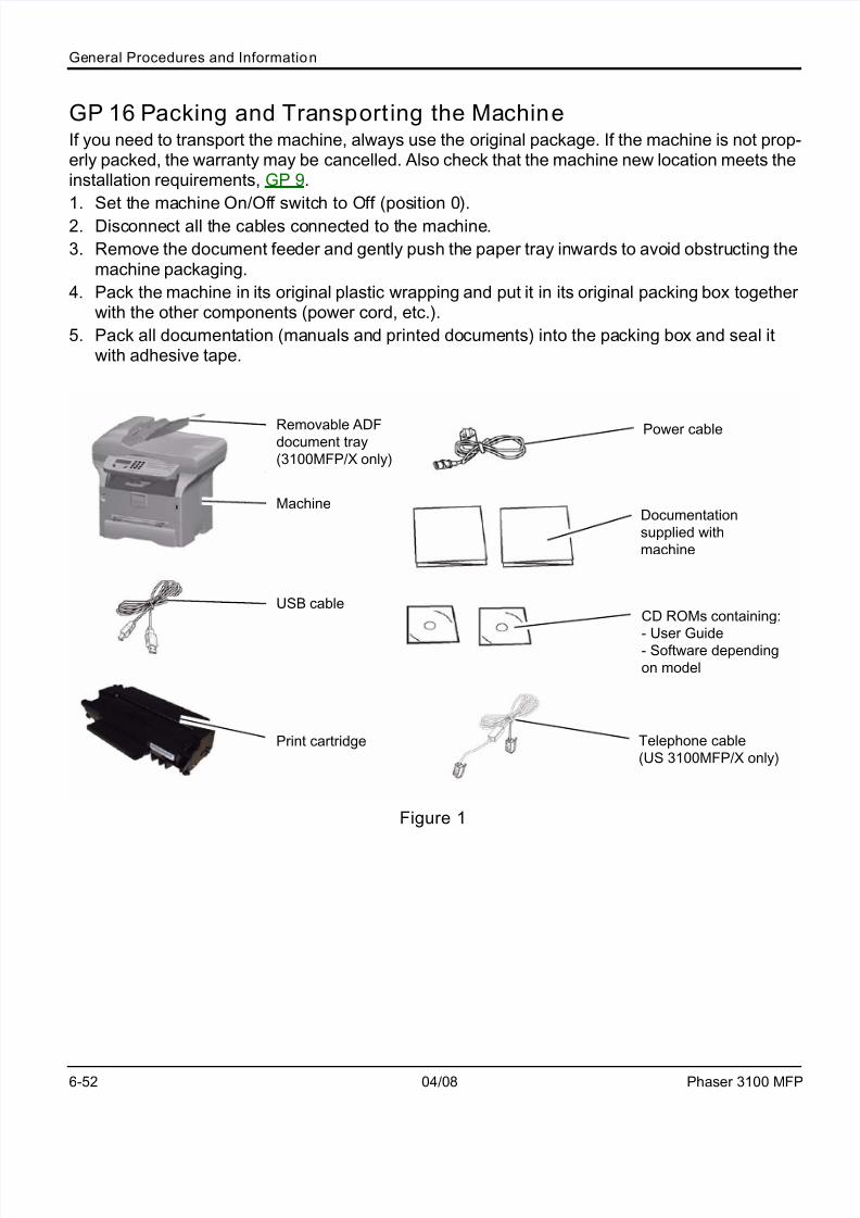
5. Pack all documentation (manuals and printed documents) into the packing box and seal itwith adhesive tape.
Figure 1
Machine
USB cable
Print cartridge
Power cable
Documentation
supplied with
machine
CD ROMs containing:
- User Guide
- Software depending
on model
Telephone cable
(US 3100MFP/X only)
Removable ADFdocument tray
(3100MFP/X only)
7/17/2019 Pages From Phaser_3100MFPServiceManual3
http://slidepdf.com/reader/full/pages-from-phaser3100mfpservicemanual3 2/44
General Procedures and Information
Phaser 3100 MFP 04/08 6-53
GP 17 Administrator FunctionsEach one of the administrator functions described here is accessible via a specific sequence ofkeys. The alphabetic keys are available via the navigation keys and via the keyboard. Forexample, to enter a sequence * A (launching scanner calibration):
1. Press the following key
2. Press the following key *.
3. Press to display all the options available until you reach A. Confirm your choice with OK.
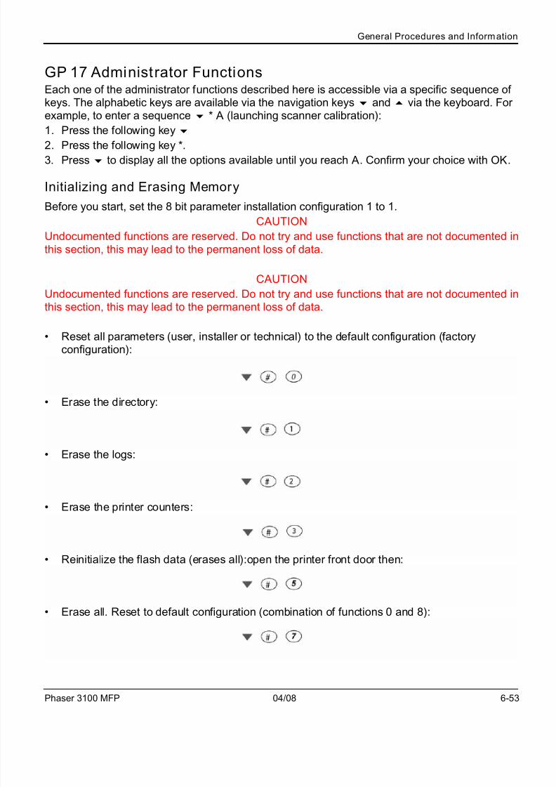
Initializing and Erasing Memory
Before you start, set the 8 bit parameter installation configuration 1 to 1.
CAUTION
Undocumented functions are reserved. Do not try and use functions that are not documented inthis section, this may lead to the permanent loss of data.
CAUTION
Undocumented functions are reserved. Do not try and use functions that are not documented inthis section, this may lead to the permanent loss of data.
• Reset all parameters (user, installer or technical) to the default configuration (factoryconfiguration):
• Erase the directory:
• Erase the logs:
• Erase the printer counters:
• Reinitialize the flash data (erases all):open the printer front door then:
• Erase all. Reset to default configuration (combination of functions 0 and 8):

7/17/2019 Pages From Phaser_3100MFPServiceManual3
http://slidepdf.com/reader/full/pages-from-phaser3100mfpservicemanual3 3/44
General Procedures and Information
6-54 04/08 Phaser 3100 MFP
• Erase all documents stored in memory:
• Erase the first job in the print queue:
• Erase Printer Error:
Then switch ON/OFF the machine.

7/17/2019 Pages From Phaser_3100MFPServiceManual3
http://slidepdf.com/reader/full/pages-from-phaser3100mfpservicemanual3 4/44
General Procedures and Information
Phaser 3100 MFP 04/08 6-55
Other Functions
Some of the administrator functions allow you to display or print the machine counters. The tablebelow details the counters available:
The counter... lists the number of...
Sent pages counter (3100MFP/X only) pages sent
Received pages counter (3100MFP/X only) pages received
Printed pages counter pages printed
Scanned pages counter pages scanned
Printed sheets counter paper sheets printed
Printer does not grip the sheet no-paper feeds detected on the printer
Jam in printer paper jams detected inside the printer
Jam in printer output paper jams detected on the exit tray
ADF misfeed (3100MFP/X only) no-paper feeds detected on the ADF scanner
ADF jams (3100MFP/X only) paper jams detected in the ADF scanner
07 Error in fax transmission (3100MFP/X only) code 07 errors detected during fax transmission (busy or no
fax answer)
01Error in fax transmission (3100MFP/X only) code 01 errors detected during fax transmission (discon-
nections)
Other errors in fax transmission (3100MFP/X only) any other error codes detected during fax transmission
64 Error in maintenance transmission
(3100MFP/X only)
code 64 errors detected during remote readout
07 Error in fax reception
(3100MFP/X only)
code 07 errors detected during fax reception (busy or no fax
answer)
Vocal call in fax reception
(3100MFP/X only)
voice calls detected during fax reception
Other errors in fax reception
(3100MFP/X only)
any other error codes detected during fax reception
Other errors in IP communication (3100MFP/X only) error codes detected during IP communication (connection
loss)
Manual and automatic ON/OFF times the machine has been switched On/Off (manually and
automatically)
Insert toner card toner card readings
Pixel number (*10000) pixels the machine has printed (*10000)
Counter TONER toner remaining in toner units
7/17/2019 Pages From Phaser_3100MFPServiceManual3
http://slidepdf.com/reader/full/pages-from-phaser3100mfpservicemanual3 5/44
General Procedures and Information
6-56 04/08 Phaser 3100 MFP
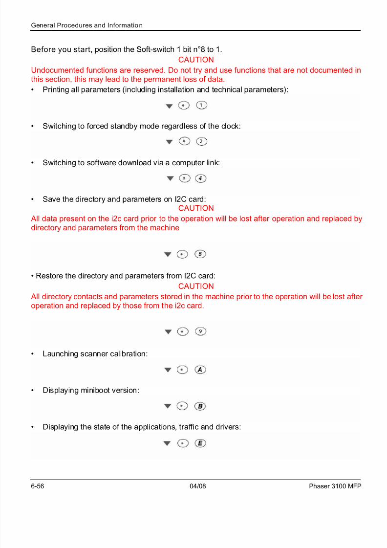
Before you start, position the Soft-switch 1 bit n°8 to 1.
CAUTION
Undocumented functions are reserved. Do not try and use functions that are not documented inthis section, this may lead to the permanent loss of data.
• Printing all parameters (including installation and technical parameters):
• Switching to forced standby mode regardless of the clock:
• Switching to software download via a computer link:
• Save the directory and parameters on I2C card:CAUTION
All data present on the i2c card prior to the operation will be lost after operation and replaced bydirectory and parameters from the machine
• Restore the directory and parameters from I2C card:
CAUTION All directory contacts and parameters stored in the machine prior to the operation will be lost after operation and replaced by those from the i2c card.
• Launching scanner calibration:
• Displaying miniboot version:
• Displaying the state of the applications, traffic and drivers:

7/17/2019 Pages From Phaser_3100MFPServiceManual3
http://slidepdf.com/reader/full/pages-from-phaser3100mfpservicemanual3 6/44
General Procedures and Information
Phaser 3100 MFP 04/08 6-57
• Display modem software version:
• Entering the serial number (with the SOS 1 bit 8 at 1):
• Displaying the internal counters:
• Displaying the GDI throughput:
• Rebooting the machine manually (with the SOS 1 bit 8 at 1):
• Displaying main software version, checksum:
• Displaying the printer firmware version and the 120V/220V configuration:
• Depending on the printer model, the machine LCD screen displays:
or
• Printing internal counters:

7/17/2019 Pages From Phaser_3100MFPServiceManual3
http://slidepdf.com/reader/full/pages-from-phaser3100mfpservicemanual3 7/44
General Procedures and Information
6-58 04/08 Phaser 3100 MFP
GP 18 Component Layout
Mechanical Components
Figure 1
Table 1:
No. Name Description
A Laser Unit Consists of the laser diode unit, cylindrical lens, f-theta lens, poly-
gon mirror motor, and other laser optical components.
B Toner Cassette Consists of the OPC drum, toner, toner application roller, develop-
ment roller, charge brush roller, cleaning blade, and other develop-
ment components.
C Upper Tray Bottom Plate Presses paper stacked in the upper paper tray against the paper
feed roller.
D Paper Feed Roller Picks up the top sheet of paper from the stack in the upper paper
tray and feeds it into the transfer area.
E Transfer Roller Applies a charge to the paper to pull the toner off the drum and onto
the copy paper.
F Pressure Roller Applies pressure to the paper during fusing.
G Heat Roller Fuses the toner to the copy paper.
H Paper Exit Roller Feeds the paper out of the printer.

7/17/2019 Pages From Phaser_3100MFPServiceManual3
http://slidepdf.com/reader/full/pages-from-phaser3100mfpservicemanual3 8/44
General Procedures and Information
Phaser 3100 MFP 04/08 6-59
Printing
Printing Processes Around the Drum
Figure 2
This machine uses a “write to black” system, using negative toner.
Charge: The charge brush roller [A] gives the OPC drum [B] surface a negative charge.
Exposure: A laser [C] writes a latent image on the drum. The charge in the area exposed by thelaser beam drops.
Development: The development roller [D] carries toner to the drum and develops the latent imageon the drum. The following charges are applied. Development bias (during printing): Toner appli-cation roller [E] Development roller [D] Switching bias (At the start and the end of any print proc-ess): Toner application roller [E] Development roller [D]
Image Transfer: The transfer roller [F] pulls the toner from the drum onto the paper [G].
Paper Separation: The antistatic brush [H] removes the charge on the underside of the paper tohelp the paper separate from the drum.
Drum Cleaning: The Discharge Lamp[L] discharge the OPC drum [B] surface, The cleaning blade[J] removes any toner remaining on the drum after the image is transferred to paper.
The high voltages [K] are supplied from the Power Supply Unit board.

7/17/2019 Pages From Phaser_3100MFPServiceManual3
http://slidepdf.com/reader/full/pages-from-phaser3100mfpservicemanual3 9/44
General Procedures and Information
6-60 04/08 Phaser 3100 MFP
Charge
Figure 3
The OPC (Organic Photoconductor) drum [A] used in this machine is small in diameter. This al-lows a very compact design.
A charge roller [B] charges the photoconductor. The charge roller has the advantage of not gen-erating ozone. A large negative voltage is applied from the Power Supply Unit board to the chargeroller. This charge roller gives the OPC drum surface a negative charge.

7/17/2019 Pages From Phaser_3100MFPServiceManual3
http://slidepdf.com/reader/full/pages-from-phaser3100mfpservicemanual3 10/44
General Procedures and Information
Phaser 3100 MFP 04/08 6-61
Figure 4
The voltage to the charge roller is supplied through the terminal [C] from the Power Supply Unitboard.
7/17/2019 Pages From Phaser_3100MFPServiceManual3
http://slidepdf.com/reader/full/pages-from-phaser3100mfpservicemanual3 11/44
General Procedures and Information
6-62 04/08 Phaser 3100 MFP
Laser Exposure
Overview
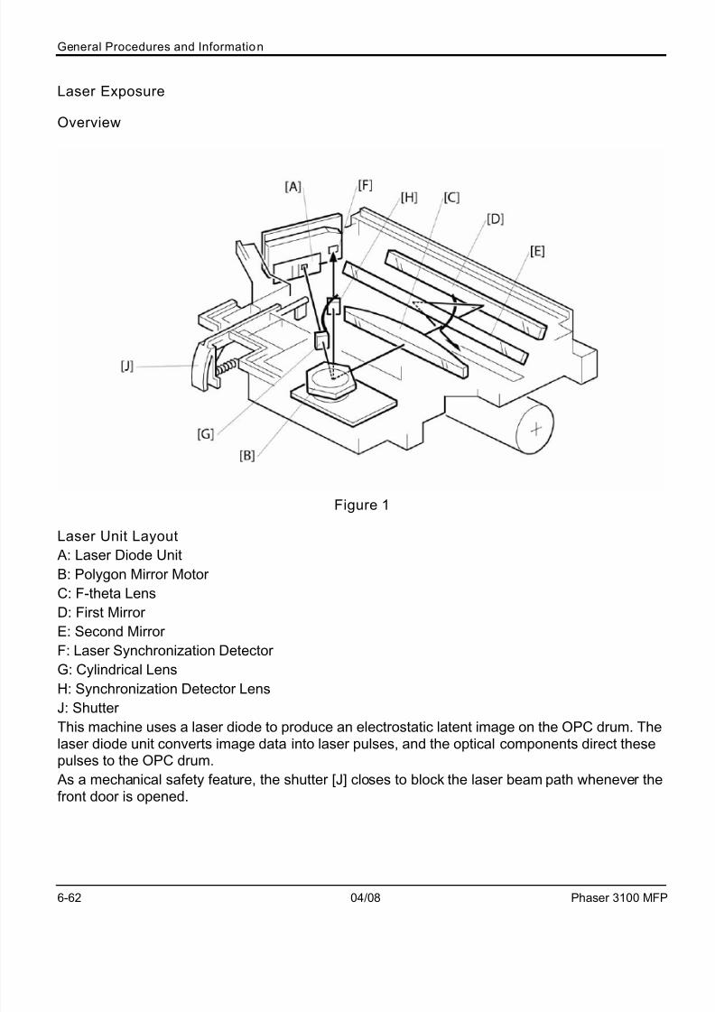
Figure 1
Laser Unit Layout
A: Laser Diode Unit
B: Polygon Mirror Motor
C: F-theta Lens
D: First Mirror
E: Second Mirror
F: Laser Synchronization Detector
G: Cylindrical Lens
H: Synchronization Detector Lens
J: ShutterThis machine uses a laser diode to produce an electrostatic latent image on the OPC drum. Thelaser diode unit converts image data into laser pulses, and the optical components direct thesepulses to the OPC drum.
As a mechanical safety feature, the shutter [J] closes to block the laser beam path whenever thefront door is opened.

7/17/2019 Pages From Phaser_3100MFPServiceManual3
http://slidepdf.com/reader/full/pages-from-phaser3100mfpservicemanual3 12/44
General Procedures and Information
Phaser 3100 MFP 04/08 6-63
Block Diagram
Figure 2
The Engine Board controls the laser diode power (APCSH) and transfers data for printing to thelaser diode (VIDEO). As an electrical safety feature, there is an interlock switch on the Engine
Board. This switch cuts +24 volts whenever the front door is opened.
Error Conditions
Laser Error
The machine detects laser synchronization signal pulses (PGSYCI) 70 milliseconds after the(LDENA) signal is sent. It detects a laser error if the pulse count does not reach the specifiednumber within 400 milliseconds.
When this occurs, the machine displays an error on the LCD panel (Error 56).
Polygon Mirror Motor Error
The machine detects a polygon mirror motor error when the (PMLOK) signal does not go low with-in 3.5 seconds of the (PMENA) signal. When this occurs, the machine displays an error on theLCD panel (Error 57).

7/17/2019 Pages From Phaser_3100MFPServiceManual3
http://slidepdf.com/reader/full/pages-from-phaser3100mfpservicemanual3 13/44
General Procedures and Information
6-64 04/08 Phaser 3100 MFP
Development
Overview [D]
Figure 3
This machine uses mono-component toner, which is composed of resin and ferrite. The toner mix-ing bar [A] stirs and carries toner to the toner application roller [B]. The toner application roller sup-plies toner to the development roller [C]. As the development roller turns past the toner meteringblade [D], only a thin coating of negatively charged toner particles stays adhered to the develop-ment roller.
During printing, a bias voltage is applied to the toner application roller and another bias voltage isapplied to the development roller. The toner is transferred from the toner application roller to thedevelopment roller by the potential difference between these two rollers.
The development roller applies toner to the exposed areas of the latent image as they turn pastthe drum.
7/17/2019 Pages From Phaser_3100MFPServiceManual3
http://slidepdf.com/reader/full/pages-from-phaser3100mfpservicemanual3 14/44
General Procedures and Information
Phaser 3100 MFP 04/08 6-65
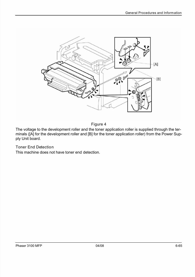
Figure 4
The voltage to the development roller and the toner application roller is supplied through the ter-minals ([A] for the development roller and [B] for the toner application roller) from the Power Sup-ply Unit board.
Toner End Detection
This machine does not have toner end detection.
7/17/2019 Pages From Phaser_3100MFPServiceManual3
http://slidepdf.com/reader/full/pages-from-phaser3100mfpservicemanual3 15/44
General Procedures and Information
6-66 04/08 Phaser 3100 MFP
Transfer and Separation
Overview
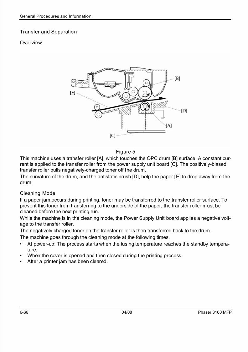
Figure 5
This machine uses a transfer roller [A], which touches the OPC drum [B] surface. A constant cur-rent is applied to the transfer roller from the power supply unit board [C]. The positively-biasedtransfer roller pulls negatively-charged toner off the drum.
The curvature of the drum, and the antistatic brush [D], help the paper [E] to drop away from the
drum.
Cleaning Mode
If a paper jam occurs during printing, toner may be transferred to the transfer roller surface. Toprevent this toner from transferring to the underside of the paper, the transfer roller must becleaned before the next printing run.
While the machine is in the cleaning mode, the Power Supply Unit board applies a negative volt-age to the transfer roller.
The negatively charged toner on the transfer roller is then transferred back to the drum.
The machine goes through the cleaning mode at the following times.
• At power-up: The process starts when the fusing temperature reaches the standby tempera-ture.
• When the cover is opened and then closed during the printing process.• After a printer jam has been cleared.

7/17/2019 Pages From Phaser_3100MFPServiceManual3
http://slidepdf.com/reader/full/pages-from-phaser3100mfpservicemanual3 16/44
General Procedures and Information
Phaser 3100 MFP 04/08 6-67
Drum Cleaning
Figure 6
The cleaning blade and the used toner tank are contained in the print cartridge.
The Discharge Lamp and A counter blade system is used for drum cleaning. The DischargeLamp[C] discharge the drum surface. The cleaning blade [A] removes any toner remaining on thedrum after the image is transferred to the paper. This removed toner is stored in the used tonertank [B].
There is no used toner overflow detection mechanism, because the used toner tank is large
enough for the lifetime of the toner cassette.

7/17/2019 Pages From Phaser_3100MFPServiceManual3
http://slidepdf.com/reader/full/pages-from-phaser3100mfpservicemanual3 17/44
General Procedures and Information
6-68 04/08 Phaser 3100 MFP
Paper Feed and Regist ration
Overview
Figure 7
Paper Feed System: Feed roller [A] and Friction pad [B]
Paper Lift Mechanism: Bottom plate with spring [C]
Sheet feeder 1 sheet feeder [D]
Tray Capacity: 250 sheets [E]
Paper End Detection: Paper end sensor [F]
Paper Size Detection: None
7/17/2019 Pages From Phaser_3100MFPServiceManual3
http://slidepdf.com/reader/full/pages-from-phaser3100mfpservicemanual3 18/44
General Procedures and Information
Phaser 3100 MFP 04/08 6-69
Paper Feed Drive Mechanism
Figure 8
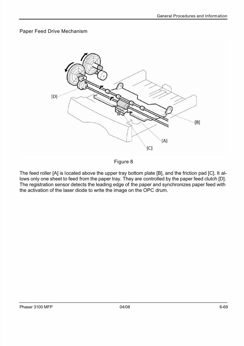
The feed roller [A] is located above the upper tray bottom plate [B], and the friction pad [C]. It al-lows only one sheet to feed from the paper tray. They are controlled by the paper feed clutch [D].The registration sensor detects the leading edge of the paper and synchronizes paper feed withthe activation of the laser diode to write the image on the OPC drum.

7/17/2019 Pages From Phaser_3100MFPServiceManual3
http://slidepdf.com/reader/full/pages-from-phaser3100mfpservicemanual3 19/44
General Procedures and Information
6-70 04/08 Phaser 3100 MFP
Paper Feed Operation
Figure 9
A: Paper feed drive gear
B: Paper feed clutch
C: Paper feed rollerD: Friction pad
E: Paper feed sensor
F: Registration sensor
The paper feed drive gear [A] always rotates while the main motor rotates, since the paper feedclutch (magnet clutch) [B] is energized to turn the paper feed roller [C].
When the paper feed clutch [B] is energized to turn the feed roller, the paper feed roller feeds onesheet of paper from the tray. The paper is fed into the machine by the registration roller.

7/17/2019 Pages From Phaser_3100MFPServiceManual3
http://slidepdf.com/reader/full/pages-from-phaser3100mfpservicemanual3 20/44
General Procedures and Information
Phaser 3100 MFP 04/08 6-71
Registration
Figure 10
The registration sensor [A] detects the leading edge of the paper and synchronizes paper feedwith the writing of the image on the drum, so that the image and paper match up properly. This
sensor also detects paper feed jams.

7/17/2019 Pages From Phaser_3100MFPServiceManual3
http://slidepdf.com/reader/full/pages-from-phaser3100mfpservicemanual3 21/44
General Procedures and Information
6-72 04/08 Phaser 3100 MFP
Tray Empty Sensor
Figure 11
The laser unit [A] has the tray empty sensor [B] built into it. The tray empty sensor detects the
presence or absence of paper. The sensor has an actuator that extends through a slot in the papertray bottom plate [C], so that the sensor is actuated when paper is placed in the upper tray.
When the upper tray runs out of paper, the actuator of the tray empty sensor moves into the slotin the upper tray bottom plate. This informs the CPU that paper has run out.
7/17/2019 Pages From Phaser_3100MFPServiceManual3
http://slidepdf.com/reader/full/pages-from-phaser3100mfpservicemanual3 22/44
General Procedures and Information
Phaser 3100 MFP 04/08 6-73
Fusing
Overview
Figure 1
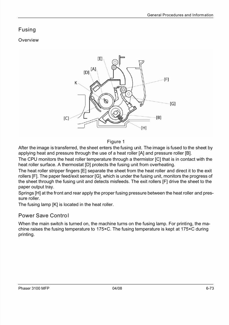
After the image is transferred, the sheet enters the fusing unit. The image is fused to the sheet byapplying heat and pressure through the use of a heat roller [A] and pressure roller [B].
The CPU monitors the heat roller temperature through a thermistor [C] that is in contact with theheat roller surface. A thermostat [D] protects the fusing unit from overheating.
The heat roller stripper fingers [E] separate the sheet from the heat roller and direct it to the exitrollers [F]. The paper feed/exit sensor [G], which is under the fusing unit, monitors the progress ofthe sheet through the fusing unit and detects misfeeds. The exit rollers [F] drive the sheet to thepaper output tray.
Springs [H] at the front and rear apply the proper fusing pressure between the heat roller and pres-sure roller.
The fusing lamp [K] is located in the heat roller.
Power Save Control
When the main switch is turned on, the machine turns on the fusing lamp. For printing, the ma-
chine raises the fusing temperature to 175×C. The fusing temperature is kept at 175×C duringprinting.

7/17/2019 Pages From Phaser_3100MFPServiceManual3
http://slidepdf.com/reader/full/pages-from-phaser3100mfpservicemanual3 23/44
General Procedures and Information
6-74 04/08 Phaser 3100 MFP
Figure 2
When the power saver timer expires, the machine automatically goes into energy saver mode.
Power saver timer
t1 =? minutes.
• After time interval t1 passes following printing, copying, scanning, or key-in [A], the LCD andall LEDís go off.
t1 + t2 =? minutes or? minutes (selectable)
• The default value is? minutes. (Economy Mode)• Pressing the Clear Modes key for more than one second will change this condition.• When the Economy Mode LED is lit, t1 + t2 =? minutes.• When the Economy Mode LED is not lit, t1 + t2 =? minutes.

7/17/2019 Pages From Phaser_3100MFPServiceManual3
http://slidepdf.com/reader/full/pages-from-phaser3100mfpservicemanual3 24/44
General Procedures and Information
Phaser 3100 MFP 04/08 6-75
Cover Interlock Switch
When the front door is opened, the interlock switch will be opened and power supply to the follow-ing parts will be cut.
• Power pack• Laser diode driver• Fan motor• Main motor
• Polygon mirror motor• Fusing lamp
7/17/2019 Pages From Phaser_3100MFPServiceManual3
http://slidepdf.com/reader/full/pages-from-phaser3100mfpservicemanual3 25/44
General Procedures and Information
6-76 04/08 Phaser 3100 MFP
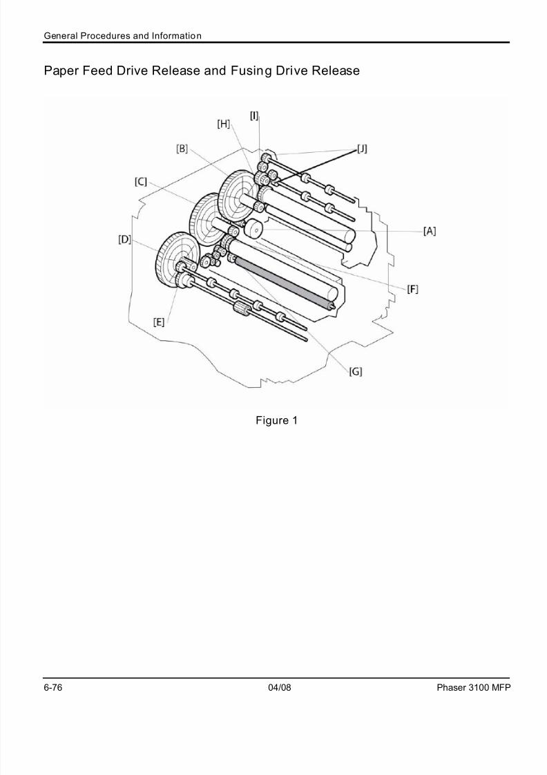
Paper Feed Drive Release and Fusing Drive Release
Figure 1
7/17/2019 Pages From Phaser_3100MFPServiceManual3
http://slidepdf.com/reader/full/pages-from-phaser3100mfpservicemanual3 26/44
General Procedures and Information
Phaser 3100 MFP 04/08 6-77
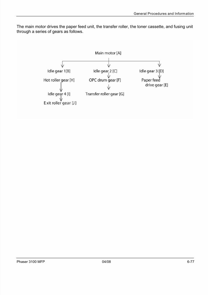
The main motor drives the paper feed unit, the transfer roller, the toner cassette, and fusing unitthrough a series of gears as follows.

7/17/2019 Pages From Phaser_3100MFPServiceManual3
http://slidepdf.com/reader/full/pages-from-phaser3100mfpservicemanual3 27/44
General Procedures and Information
6-78 04/08 Phaser 3100 MFP
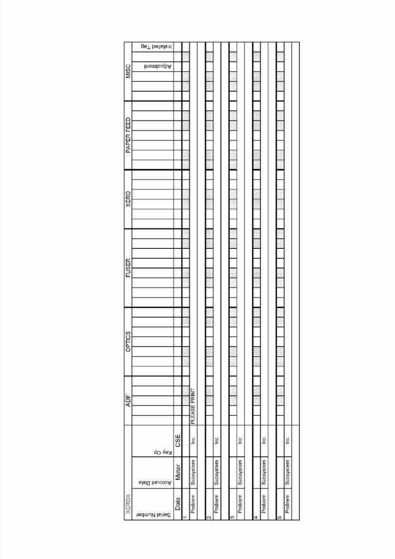
GP 19 Service Log
Service Log
Use the service log to record all service procedures. The service log is included at the end of the
manual.

7/17/2019 Pages From Phaser_3100MFPServiceManual3
http://slidepdf.com/reader/full/pages-from-phaser3100mfpservicemanual3 28/44
Wiring Data
Phaser 3100 MFP 04/08 7-1
7 Wiring Data
WD1 Connector Information ..................................................................................................... 7-3

7/17/2019 Pages From Phaser_3100MFPServiceManual3
http://slidepdf.com/reader/full/pages-from-phaser3100mfpservicemanual3 29/44
Wiring Data
7-2 04/08 Phaser 3100 MFP
This page is intentionally blank

7/17/2019 Pages From Phaser_3100MFPServiceManual3
http://slidepdf.com/reader/full/pages-from-phaser3100mfpservicemanual3 30/44
Wiring Data
Phaser 3100 MFP 04/08 7-3
WD1 Connector Information
Figure 1 Overview of the position of the connectors and sockets for the control panelPWB (bottom view):
Table 1: List of connectors:
Connector Topography Number of points Gender Position
CPU Connection P4200 16 Female Elbow top contact
LCD P4002 10 Female Elbow, top contact
Smart card P4001 10 Female
Table 2: CPU - P4200: CPU connection
Pin Signal Input/Output Utilization
1-7-8-10-15 GND - Ground
2 FERCAP I Detection of smart card
3 CVCC I/O Smart card power supply (3.3V) (control-
led by I/O CVCC)
4 CLKPUCE O Smart card clock
5 RSTPUCE I Smart card reset
6 IOPUCE I/O Smart card data
9 SCLKPUP O Serial clock link for differential registers
11 RXPUP I Sending data from the front panel
12 TXPUP O Sending data from the CPU
13 STROB1 - Out-of-register strobe to control the key-
board

7/17/2019 Pages From Phaser_3100MFPServiceManual3
http://slidepdf.com/reader/full/pages-from-phaser3100mfpservicemanual3 31/44
Wiring Data
7-4 04/08 Phaser 3100 MFP
14 STROB2 - Out-of-register strobe to control the dis-
play
16 P5V - 5V power supply
Table 3: LCD - P4002: LCD interface
Pin Signal Input/Output Utilization
1 GND - Ground
2 V0 O LCD Contrast
3 RS O Selection of registers
4 R/W O Read or Write (driver configured to write in
0V)
5 LCD_E O Enable Signal (active at 1)
6 VCCLCD - Vcc: 4.5V to 5.5V
7 DB4 O Data (Bit 4)
8 DB5 O Data (Bit 5)9 DB6 O Data (Bit 6)
10 DB7 O Data (Bit 7)
Table 4: Smart card - P4001: connect ion with the smart card
Pin Signal Input/Output Utilization
1 CVCC O Smart card power supply (3.3V)
2 RSTPUCE O Smart card reset
3 CLKPUCE O Smart card clock
4 - - Not connected
5 GND - Ground
6 - - Not connected
7 IOPUCE I/O Smart card data (input/output)
8 - - Not connected
S1 GND - Ground
S2 FERCAP I Smart card detection
Table 2: CPU - P4200: CPU connection
7/17/2019 Pages From Phaser_3100MFPServiceManual3
http://slidepdf.com/reader/full/pages-from-phaser3100mfpservicemanual3 32/44
Wiring Data
Phaser 3100 MFP 04/08 7-5
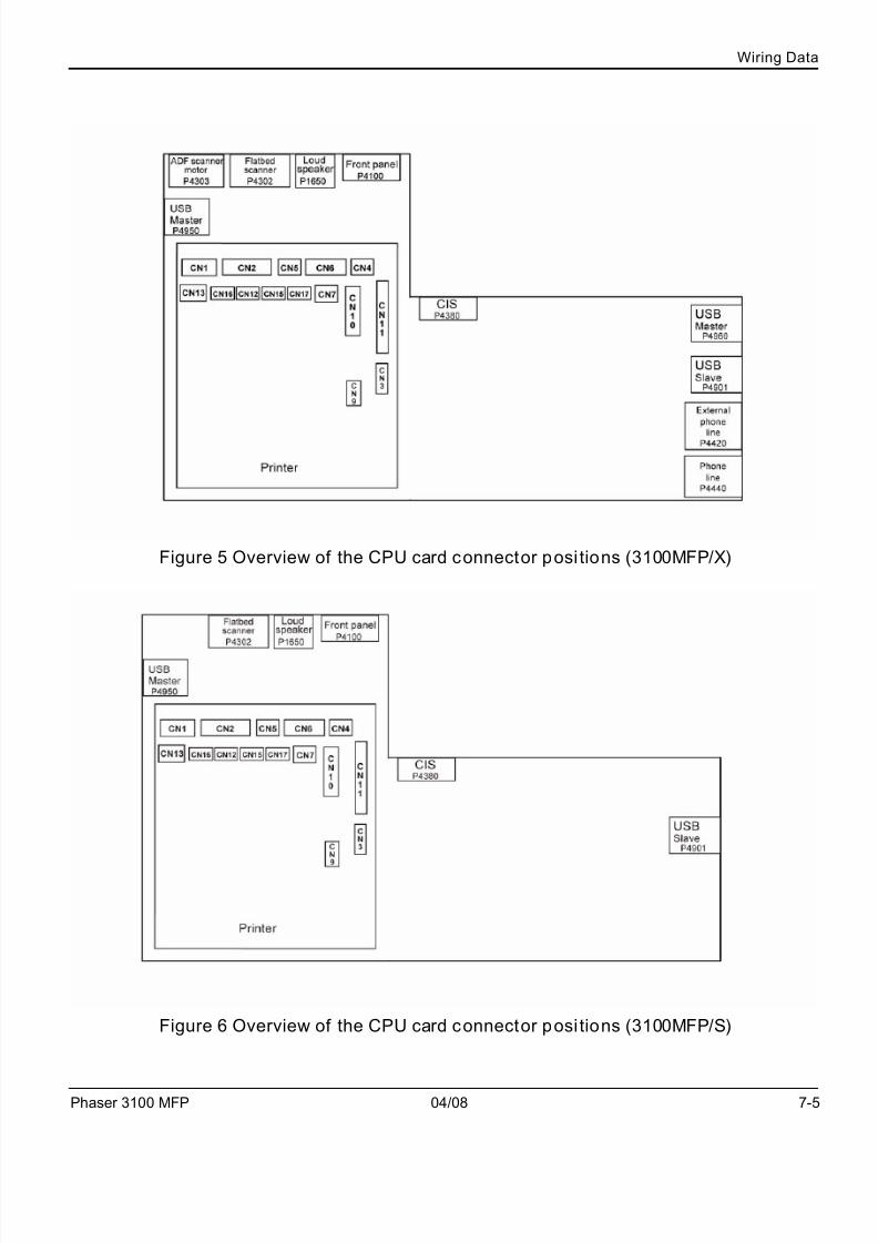
Figure 5 Overview of the CPU card connector positions (3100MFP/X)
Figure 6 Overview of the CPU card connector positions (3100MFP/S)
7/17/2019 Pages From Phaser_3100MFPServiceManual3
http://slidepdf.com/reader/full/pages-from-phaser3100mfpservicemanual3 33/44
Wiring Data
7-6 04/08 Phaser 3100 MFP
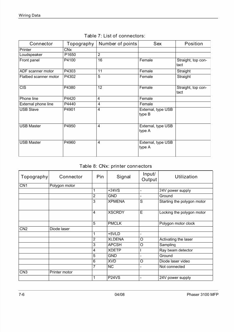
Table 7: List of connectors:
Connector Topography Number of points Sex Position
Printer CNx
Loudspeaker P1650 2
Front panel P4100 16 Female Straight, top con-
tact
ADF scanner motor P4303 11 Female Straight
Flatbed scanner motor P4302 5 Female Straight
CIS P4380 12 Female Straight, top con-
tact
Phone line P4420 4 Female
External phone line P4440 4 Female
USB Slave P4901 4 External, type USB
type B
USB Master P4950 4 External, type USB
type A
USB Master P4960 4 External, type USB
type A
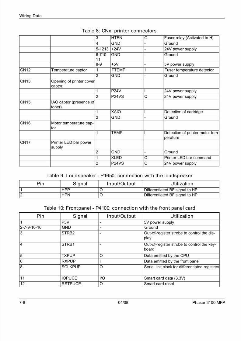
Table 8: CNx: printer connectors
Topography Connector Pin Signal Input/Output
Utilization
CN1 Polygon motor
1 +24VS - 24V power supply
2 GND - Ground
3 XPMENA S Starting the polygon motor
4 XSCRDY E Locking the polygon motor
5 PMCLK Polygon motor clock
CN2 Diode laser
1 +5VLD -
2 XLDENA O Activating the laser
3 APCSH O Sampling
4 XDETP I Ray beam detector
5 GND - Ground
6 XVD O Diode laser video
7 NC - Not connected
CN3 Printer motor
1 P24VS - 24V power supply

7/17/2019 Pages From Phaser_3100MFPServiceManual3
http://slidepdf.com/reader/full/pages-from-phaser3100mfpservicemanual3 34/44
Wiring Data
Phaser 3100 MFP 04/08 7-7
2 GND - Ground
3 P5V -
4 XMMENA
5 MMCLK
6 MMCW7 XMMLOCK
8 MMGAIN
CN4 Fan
1 FANEMA O Fan in operation motor signal
2 GND - Ground
3 FANLOCK
CN5 Paper output clutch
1 +24VS - 24V power supply
2 XFPCL O Electric paper clutch signal
CN6 Paper detection captors
1-4-7 GND - Ground
2 XFEED I Paper feed signal captor
3-6-9 +5V - 5V power supply
5 XREGIST I Register of signal captors
8 XMANUAL I Manual paper feed signal cap-
tor
CN7 Paper output captor
1 GND - Ground2 XEXIT I Four paper output signal cap-
tors
3 +5V - 5V power supply
CN9 Debug
1 +5V - 5V power supply
2 DBGRXD I Debug receipt
3 DBGTXD O Debug command
4 GND - Ground
CN10 High voltage
1 TRAPWM0 O PWM signal for transfer of
charger (+)
2 TRAPWM1 O PWM signal for transfer of
charger (-)
3 BIASPWM O PWM development signal
4 CHEPWM O PWM signal charger
CN11 Power supply
1 HTON O Phase Fuser control
2 ZEROC I Control signal
Table 8: CNx: printer connectors
7/17/2019 Pages From Phaser_3100MFPServiceManual3
http://slidepdf.com/reader/full/pages-from-phaser3100mfpservicemanual3 35/44
Wiring Data
7-8 04/08 Phaser 3100 MFP
3 HTEN O Fuser relay (Activated to H)
4 GND - Ground
5-1213 +24V - 24V power supply
6-710-
11
GND - Ground
8-9 +5V - 5V power supply
CN12 Temperature captor 1 FTEMP I Fuser temperature detector
2 GND - Ground
CN13 Opening of printer cover
captor
1 P24V I 24V power supply
2 P24VS O 24V power supply
CN15 IAO captor (presence of
toner)
1 XAIO I Detection of cartridge
2 GND - GroundCN16 Motor temperature cap-
tor
1 TEMP I Detection of printer motor tem-
perature
CN17 Printer LED bar power
supply
2 GND - Ground
1 XLED O Printer LED bar command
2 P24VS O 24V power supply
Table 9: Loudspeaker - P1650: connection with the loudspeaker
Pin Signal Input/Output Utilization
1 HPP O Differentiated BF signal to HP
2 HPN O Differentiated BF signal to HP
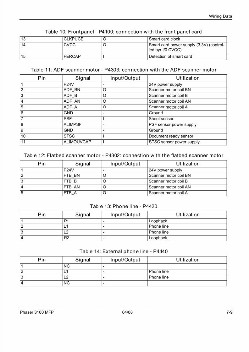
Table 10: Frontpanel - P4100: connection with the front panel card
Pin Signal Input/Output Utilization
1 P5V - 5V power supply
2-7-9-10-16 GND - Ground
3 STRB2 - Out-of-register strobe to control the dis-
play4 STRB1 - Out-of-register strobe to control the key-
board
5 TXPUP O Data emitted by the CPU
6 RXPUP I Data emitted by the front panel
8 SCLKPUP O Serial link clock for differentiated registers
11 IOPUCE I/O Smart card data (3.3V)
12 RSTPUCE O Smart card reset
Table 8: CNx: printer connectors
7/17/2019 Pages From Phaser_3100MFPServiceManual3
http://slidepdf.com/reader/full/pages-from-phaser3100mfpservicemanual3 36/44
Wiring Data
Phaser 3100 MFP 04/08 7-9
13 CLKPUCE O Smart card clock
14 CVCC O Smart card power supply (3.3V) (control-
led byr I/0 CVCC)
15 FERCAP I Detection of smart card
Table 11: ADF scanner motor - P4303: connection with the ADF scanner motor
Pin Signal Input/Output Utilization
1 P24V - 24V power supply
2 ADF_BN O Scanner motor coil BN
3 ADF_B O Scanner motor coil B
4 ADF_AN O Scanner motor coil AN
5 ADF_A O Scanner motor coil A
6 GND - Ground
7 PSF I Sheet sensor
8 ALIMPSF - PSF sensor power supply
9 GND - Ground
10 STSC I Document ready sensor
11 ALIMOUVCAP I STSC sensor power supply
Table 12: Flatbed scanner motor - P4302: connection with the flatbed scanner motor
Pin Signal Input/Output Utilization
1 P24V - 24V power supply
2 FTB_BN O Scanner motor coil BN
3 FTB_B O Scanner motor coil B
4 FTB_AN O Scanner motor coil AN
5 FTB_A O Scanner motor coil A
Table 13: Phone line - P4420
Pin Signal Input/Output Utilization
1 R1 - Loopback
2 L1 - Phone line
3 L2 - Phone line
4 R2 - Loopback
Table 14: External phone line - P4440
Pin Signal Input/Output Utilization
1 NC -
2 L1 - Phone line
3 L2 - Phone line
4 NC -
Table 10: Frontpanel - P4100: connection with the front panel card
7/17/2019 Pages From Phaser_3100MFPServiceManual3
http://slidepdf.com/reader/full/pages-from-phaser3100mfpservicemanual3 37/44
Wiring Data
7-10 04/08 Phaser 3100 MFP
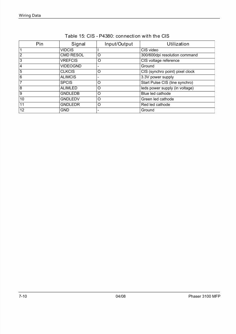
Table 15: CIS - P4380: connection with the CIS
Pin Signal Input/Output Utilization
1 VIDCIS I CIS video
2 CMD RESOL O 300/600dpi resolution command
3 VREFCIS O CIS voltage reference
4 VIDEOGND - Ground
5 CLKCIS O CIS (synchro point) pixel clock
6 ALIMCIS - 3.3V power supply
7 SPCIS O Start Pulse CIS (line synchro)
8 ALIMLED O leds power supply (in voltage)
9 GNDLEDB O Blue led cathode
10 GNDLEDV O Green led cathode
11 GNDLEDR O Red led cathode
12 GND - Ground
7/17/2019 Pages From Phaser_3100MFPServiceManual3
http://slidepdf.com/reader/full/pages-from-phaser3100mfpservicemanual3 38/44
Wiring Data
Phaser 3100 MFP 04/08 7-11
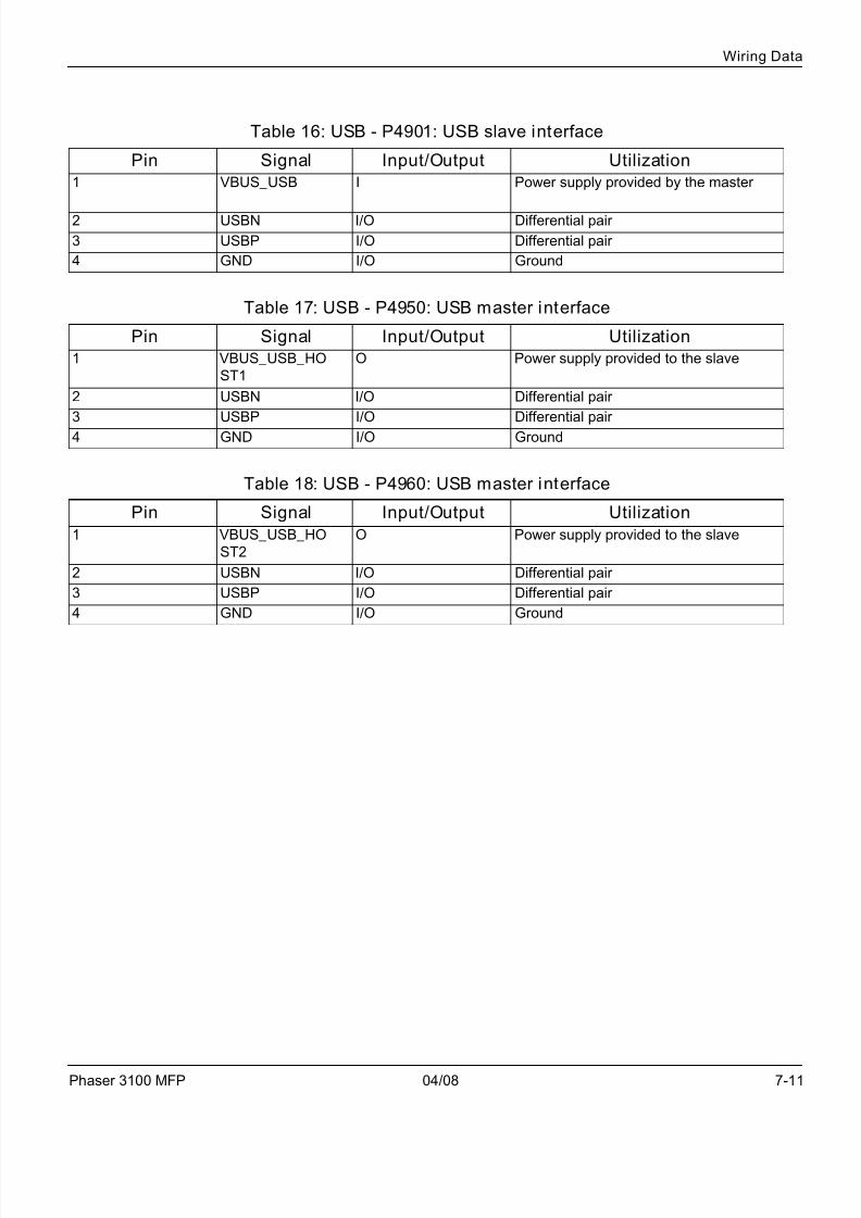
Table 16: USB - P4901: USB slave interface
Pin Signal Input/Output Utilization
1 VBUS_USB I Power supply provided by the master
2 USBN I/O Differential pair
3 USBP I/O Differential pair
4 GND I/O Ground
Table 17: USB - P4950: USB master interface
Pin Signal Input/Output Utilization
1 VBUS_USB_HO
ST1
O Power supply provided to the slave
2 USBN I/O Differential pair
3 USBP I/O Differential pair
4 GND I/O Ground
Table 18: USB - P4960: USB master interface
Pin Signal Input/Output Utilization
1 VBUS_USB_HO
ST2
O Power supply provided to the slave
2 USBN I/O Differential pair
3 USBP I/O Differential pair
4 GND I/O Ground

7/17/2019 Pages From Phaser_3100MFPServiceManual3
http://slidepdf.com/reader/full/pages-from-phaser3100mfpservicemanual3 39/44
Wiring Data
7-12 04/08 Phaser 3100 MFP
This page is intentionally blank
7/17/2019 Pages From Phaser_3100MFPServiceManual3
http://slidepdf.com/reader/full/pages-from-phaser3100mfpservicemanual3 40/44

7/17/2019 Pages From Phaser_3100MFPServiceManual3
http://slidepdf.com/reader/full/pages-from-phaser3100mfpservicemanual3 41/44
Form EH&S-700 Rev 2.0 (21 February 2008) North America Letter Format
EHS 700 - Health & Safety Incident Report Formfor Incidents Involving a Xerox Product
For incidents i n Canada:PIPEDA consent given YES NO EH&S Office Use ONLY EH&S Incident Reference Number: PIPEDA is the Canadian “Personal Information Protection and Electronic Documents Act.”
*Date Of Incident (mm / dd / yy):
Product Description
*Model No. or Product Name:
Product Serial Number : Serial Number(s) of Accessory (ies):
Installation Date: Total Copy Meter :
Date of last service maintenance:
List damaged and affected part(s) of the machine by descripti on and part number :
*Description Part Number
*Location of product and affected part(s):
Customer Identification*Customer Name: *Name of Customer Contact Person:
*Telephone:*Address: E-mail:
Fax:
Customer Service Engineer Identification*Name (required for Xerox serviced equipment): Employee: E-mail:
Location: *Phone (required for Xerox serviced equipment):
Individual Providing Notification
*Name: *Title: *Telephone Number :
*Organization: E-Mail:
Mailing Address: *Date Report Submi tted:
* Required information is preceeded by asterisk, title shown in red, turquoise wash background

7/17/2019 Pages From Phaser_3100MFPServiceManual3
http://slidepdf.com/reader/full/pages-from-phaser3100mfpservicemanual3 42/44
EHS 700 - Health & Safety Incident Report Form for Page 2Incidents Involving a Xerox Product
Form EH&S-700 Rev 2.0 (21 February 2008) North America Letter Format
Details of Incident
*Description Of Incident: (Check all that apply)
Smoke
Describe quantity and duration of smoke:
Fire with open flames seen
Electric shock to operator or service representative
Physical injury/illness to operator or service representative
Describe:
Other, Describe:
MANDATORY DESCRIPTION (above): Provide a detailed description of all valid factors that may have
contributed to the incident. Hardware involved in the incident should be preserved and retained for furtherinvestigation should investigation be deemed necessary by EH&S.
LIST INCIDENT DESCRIPTIONS AND SUPPORT DIAGRAMS/DATA INCLUDED OR ATTACHED:
*Any damage to customer property? No Yes Describe:
*Did external emergency response provider(s) such as fi re department, ambulance, etc. respond ?
No Yes Identify: (i.e., source, names of individuals)
App arent cause of incid ent ( ident ify par t th at is suspect t o be responsible for the inc ident)
*Preliminary actions taken to mitigate incident:
Instructions: E-mail or fax both pages of this completed form to EH&S: • For incidents in Xerox Europe and Developing Markets East
(Middle East, Africa, India, China, and Hong Kong)Submit to Elaine Grange
e-mail: [email protected] or fax : +44 (0) 1707 35 3914 [Intelnet 8*668 3914]
• For incidents in North America and Developing Markets West (Brazil, Mexico, Latin America North and Latin America South,Submit form to Doris Bush
e-mail: [email protected] or fax 888-845-0908 [1-585-422-7918 / Intelnet 8*222-7734]
* Required information is preceeded by asterisk, title shown in red , turquoise wash background

7/17/2019 Pages From Phaser_3100MFPServiceManual3
http://slidepdf.com/reader/full/pages-from-phaser3100mfpservicemanual3 43/44
XEROX EUROPE
PUBLICATION COMMENT SHEET
Please copy this master sheet and use it to help us to improve this publication. We would like you to tell us aboutimprovements to its accuracy, format and quality.Please give specific references, i.e.: page numbers and figure numbers and attach marked up photocopies wher-
ever possible. If you have identified a solution please include your suggestions with your reply.Please also answer the customer satisfaction question set.When you have completed the PCS, send it by internal mail to the address below. You will receive an acknowl-edgement and feedback on your comments. Please ensure that your name and CBU/District location code arefully completed.
NAME:
JOB TITLE:
ENGINEER NUMBER:
CONTACT TELEPHONE NUMBER:
DATE:
OPERATING COMPANY:
CBU/DISTRICT LOCATION CODE:
PRODUCT AND PUBLICATIONTITLE:
PUBLICATION REVISIONDATE:
SOFTWARE REVISION LEVEL:
PAGE NUMBER: COMMENTPlease submit a marked-up photocopy of the relevant pages
CUSTOMER SATISFACTION QUESTION SET
QUESTION NOTAPPLICABLE
VERYSATISFIED
SATISFIED NEITHERSATISFIED
NORDISSATISFIED
DISSATISFIED VERYDISSATISFIED
DO YOU FIND THE MANUAL IS TECHNICALLY
ACCURATE?
DO YOU FIND THE FORMAT OF THE MANUAL EASY
TO USE?
WHAT IS YOUR OVERALL SATISFACTION LEVEL
WITH THE MANUAL
FOR OFFICE USE ONLY Global Knowledge & Language ServicesXerox EuropeEnterprise Centre
Bessemer RoadWelwyn Garden CityHertfordshire AL7 1HEEnglandAttention: Phil Hayes
RECEIVED DATE:
PCS. NUMBER:
MANAGER:
DUE DATE:

7/17/2019 Pages From Phaser_3100MFPServiceManual3
http://slidepdf.com/reader/full/pages-from-phaser3100mfpservicemanual3 44/44
XEROX EUROPE