page (78-118)
TRANSCRIPT

SOIL BIO-ENGINEERING WITH JUTE GEOTEXTILES
FOR SLOPE EROSION CONTROL
Tapobrata Sanyal
INTRODUCTION
Stability of hill slopes and control of erosion are two different phenomena that warrant separate
remedial actions. Hill slope stability is in general dependent on slope movement. Land slides
are forms of hill slope instability. Terzaghi (1950), Sharpe (1938), Varnes (1978) investigated
the causes of land slides. Varnes identified five principal types of mass soil movements.
According to him land slides are in general caused by a combination of a number of soil
movements. There could be geological, geotechnical, natural and anthropogenic factors behind
soil movements and land slides. Remedial measures depend on the causes triggering such
mass soil movements.
Precipitation is the principal agent of surficial erosion of hill slopes. The extent of such erosion
depends on the intensity of precipitation, erodibility of soil covering the hill slope, the hill
slope that influences the velocity of surface run-off and consequently migration of detached
soil particles. Deforestation is considered as a major contributing factor to erosion. The detached
soil particles and debris are carried by the run-off and get deposited at the slope-bottom
downhill choking the natural drainage. Such erosions, if allowed to sustain, may take the
shape of slides in future. Erosion of top soil of hill slopes should be taken seriously and
controlled at the earliest opportunity as; otherwise, it may also destabilize the hill slope on a
massive scale. The other critical factor in hill slope erosion is gradual build-up of pore water
pressure which has to be dissipated by suitable measures. Slope inclination is also an important
factor in the sense that steeper the slope, higher is the velocity of surface run-off which is
directly related to soil-migration.
Today the global trend to combat soil erosion in all types of soil is to adopt soil bio-engineering
measures. The emphasis is on creation of an appropriate vegetative cover that is sturdy and
capable of exerting a binding action on soil through roots. The major advantage is to provide
a cover on slopes so that rains can not strike slope soil directly and disintegrate it. Jute
Geotextiles (JGT) can provide an excellent support by three-fold actions viz. as a cover over
slope, as an agent to lessen the velocity of surface run-off and as a partial receptor of detached
soil particles. JGT can be used in other corrective measures as well as supplement.
This paper highlights the advantages of Jute Geotextiles (JGT) as a supplement of soil bio-
engineering measures to control slope erosion in hills and elsewhere.
What is Soil Bio-engineering ?
Soil bio-engineering is a technology that judiciously combines vegetation and living plants
as the principal construction material often in association with conventional structural measures.
The stress is on hydro-geological aspects of soil consolidation. It is a natural way of stabilization
of exposed vulnerable and failed soil encountered in slopes and river banks. Additionally the
technology is concordant with the ambient eco-system.
76

The concept is not new. It was tried in ancient civilizations such as China centuries back.
Plants in the shape of fascicles were used to protect soil against erosion. Only in the early part
of the 20th century some of the European countries such as Italy, Holland, Germany, Austria
and Switzerland experimented with the technique and evaluated performance of such efforts.
The technology underwent refinement over the years and is now considered as a viable
alternative to exclusive structural intervention being done with the help of man-made inert
constructional materials to control soil distresses. Soil bio-engineering is considered as a
component of sustainable development strategy. Now countries like the USA, Brazil are
favouring the technology for ecological reasons primarily.
The functions of the technology are basically three viz.
• technical i.e. reduction of erosion through soil consolidation
• eco-compatibility by providing space for natural dynamics and
• economy
Use of man-made constructional materials is often fraught with environmental hazards. Soil
bio-engineering uses ‘nature’ to control its own malady.
Phenomenon of Soil Erosion
An analysis may be made considering the mechanism of detachment of top soil as a result of
precipitation, run-off generation and transport of detached soil particles by run-off. The
mechanism is best understood by the fundamental concept behind formulation of Universal
Hydrologic Equation (UHE). The equation considers three modes for dissipation of
precipitation. These are — in-soil penetration, surface run-off and overland storage. In-soil
penetration depends on hydraulic conductivity and the extent of saturation of the soil. The
larger is the hydraulic conductivity of soil, the greater is the penetration and correspondingly
the lower is the surface run-off. On the other hand, the more the soil is saturated, the less will
be the in-soil penetration resulting in higher surface run-off.
Kinetic energy of rain drops dissociates the top soil. Detachment of soil particles as a result of
impact of rain drops, run-off generation and their transport by the overland flow take place in
sequence.
Run-off usually flows in layers in the form of sheet (“sheet flow”) and picks up velocity as it
flows down the slope. Topography of the land, especially the downward slope of the land,
influences the velocity of surface run-off. Steeper the slope, higher is the velocity and greater
is its capacity to erode. Erodibility of soil (a measure of vulnerability or ease of disintegration
of soil) is also a critical parameter in the phenomenon of erosion.
Overland storage is interception of run-off. If a portion of the overland flow can be intercepted
as storage, the erosive force will get somewhat reduced.
Providing a cover over soil is thus very important to put surficial erosion on check. Adequate
cover over soil will obstruct its direct disintegration by rain drops. A properly designed cover
made of an appropriate material can help entrap the disintegrated soil particles, can reduce
the velocity of surface run-off by posing successive cross barriers on its downward flow path
and can also ensure partial overland storage. At the same time it is important to keep an eye
on the costs for providing such a cover and on its eco-compatibility.
Dependence on artificial cover at the initial stages will cease once vegetation takes a firm root
77

into the soil. In fact this is the most desirable solution from the point of view of economy as
well as eco-concordance.
Phenomenon of Hill Slope De-stabilization
Causes behind failure of hill slopes are far more complex. The processes that trigger movement
of soil in a hill slope are more than one and are generically known as ‘mass wasting’ or ‘mass
movement’. They take place on a range of time scales. Sudden failures occur when the stresses
imposed on the slope materials outstrips the strength of resistance of the hill slope system for
short periods.
The principal cause of stress is the gravitational force which is related to the slope angle and
the weight of hill slope sediment and rock. The relationship may be expressed as,
F= W Sin α where, F is the gravitational force, W is the weight of the material occurring at
some point on the slope and α is the slope angle.
The shear strength of a hill slope system depends on the shearing resistance of the materials.
Presence of excess moisture inhibits the inter-particulate effective stress to be operative and
disturbs the cohesive bond between particles. Prolonged precipitation not only disturbs the
inter-particulate bond, but also adds to the dead weight of slope materials enhancing the
gravitational force.
The other major cause is seismic disturbances which, by shaking up the slope materials, can
increase downward stress or decrease the shearing resistance of the hill slope materials.
The third agent is surface run-off which moves in a continuous layer (“sheet wash”) carries
with it the loose and detached particles on a hill slope as already indicated. Sometimes
topographic irregularities transform sheet wash into small channels called “rills”. Several rills
may converge to form larger channels generating turbulence and velocities sufficient to
transport slope materials.
Two common forms of mass movements are rotational slides/slips and mud flow. Rotational
slides occur along clearly defined curved planes of weakness and are aided by erosion at the
slope base. Super saturation of slope materials leads to near-liquefaction of slope materials
propelling a mud-like flow along the hill slope.
In fact it is necessary to conduct both geological and geotechnical investigations. Geological
features such as bedding planes, joint planes, faults, folds, shear zones, type and quality of
rocks, location of soft pockets/beds if any, orientation of the discontinuities are to be
investigated. Geo-morphological features such as erosional and depositional zones are to be
noted.
Geotechnical investigation should include determination of the average grain size, Atterberg
limits, hydraulic conductivity, angle of internal friction, natural moisture content etc of the
slope materials. Seasonal variation of water table should also be investigated.
There is need for undertaking standard stability analyses of slopes on the basis of the data
collected during the investigations.
Principles of Corrective Measures
In case of the existing hill slopes that call for stabilization, the basic principles underlying the
remedial measures are two-fold viz.,
• reduction of the forces propelling failures
• augmentation of the resisting forces
78
To reduce the intensity of propelling forces, the first step would be to ensure an efficient
drainage system both surface and under surface. It may often be necessary to guide rain
water through a safe path along the slope in the shape of open conduits (“cascading”). This
may need structural modifications in the slope. The safe path should follow the contours.
The other measure would be to prevent direct ingress of rain water on the slope. A cover of
vegetation should greatly reduce penetration of water under. Sealing of tension cracks is also
done for prevention of intrusion of water inside.
Sub-surface drainage is more difficult. The main objective is to drain off water from inside.
Concealed horizontal drains, trench drains, vertical drainage systems may be put in place for
this purpose. Installation of horizontal drains is a conventional practice to off load over-
pressure inside.
Reduction of imposed weight is done by flattening of slopes and providing relief benches/
berms. Segmenting long slopes is a conventional method of relieving the stress burden.
Removal of unstable soil mass and easing of slopes could be additional options.
Structural measures are adopted to enhance the resisting forces. Balancing berms/counterweight
fills are constructed at the toe of the slope. Cuts and fills are effective in correcting deep
seated slides provided the overall slope stability is not impaired.
Construction of reinforced earth fills, sausage walls with geogrids and restraining structures
is also resorted to in appropriate cases.
The conventional practices to ensure stability of vulnerable slopes are aimed at structural
corrections such as gabions (wire crates), mortared or dry masonry, soil-nailing, reinforced
earth, mass concrete, wall built on bored piles. But there are limitations to adoption of such
measures.
Hill Roads Manual (IRC: SP: 48:1998) published by The Indian Roads Congress (IRC) provides
detailed guide lines for conventional remediation practices.
There are however practical difficulties in executing structural corrections. Howell et al (2006)
has listed the difficulties that are encountered in resorting to geotechnical corrections only.
These are—
• lack of working space in hill slopes
• difficulty in reaching the deep-seated bed-rock for foundation
• variation in material strength of fill over depth
• site-specific drainage design that requires regular maintenance
• lack of geotechnical skill on the part of the executing engineers
The global experience in this direction suggests adoption of a blend of the conventional low
cost geotechnical corrections aided by bio-engineering measures. Such exercises have been
applied successfully in Nepal. The key lesson learnt through these experimentations is that
geotechnical and bio-engineering measures need be integrated for effective hill slope
management.
How Soil Bio-engineering helps in Erosion Control
As already indicated in the preceding, soil bio-engineering in erosion control is basically use
of suitable types of vegetation that helps control soil erosion in slopes singly or in conjunction
with geotechnical measures. Effects of geotechnical measures get enhanced as a result of
79

using bio-engineering measures. The most types of vegetation perform five functions –
�• armouring i.e. providing a cover of vegetation
• reinforcement i.e. providing a net work of roots that increases the resistance of soil
• against shear
• catching i.e. intercepting soil particles disintegrated as a result of precipitation or
otherwise
• anchoring i.e. holding weak soil
• drainage i.e. dissipation of surface and sub-surface water pressure.
Vegetation should be planted in such a way as will facilitate surface drainage and intercept
dissociated soil particles. Pore water pressure in the underground is eased off due to
transpiration through roots.
It is pertinent to mention that soil bio-engineering measures, besides being environmentally
concordant, substantially reduce accumulation of soil particles at the slope-toe and prevent
clogging of road-side drains.
It has to be admitted that the role of vegetation is not as simple as it may appear in so far as its
hydrological and mechanical effects are concerned. Plants used in groups in a suitable
configuration show better effects. It has been found that plantation of vegetation at an angle
to the slope inclination is more effective than plantation across the slope (Howell 2006).
Vegetation improves the integrity of a slope as a whole and strengthens the top 500 mm or so
of the ground which is its most vulnerable part.
Parameters governing slope stability cannot be generalized. The governing parameters are
site-specific. Selection of vegetation will depend on local climate, soil characteristics and
other factors. Vegetation with deep roots and high survivability rate should be chosen
considering the climatic and geotechnical ambience.
It is pertinent to mention that different parts of a plant perform specific functions. Roots
increase hydraulic conductivity of soil and reinforce them by performing functions of
anchorage, absorption, conduction and storage. Stems help in interception. Leaves aid storage
and add to the beauty. In fact vegetation helps dissipate the kinetic energy of rain drops,
attenuates the effects of wind and helps reduce the velocity of overland flow. Vegetation
propagates a self-sustaining ecological cycle. The most critical aspect of biological intervention
is the choice of plants and vegetation.
Use of Jute Geotextiles (JGT) in Soil Bio-engineering
Jute Geotextiles (JGT) may be conveniently used in quite a few of the remedial measures as
indicated as supplement.
Jute is a natural ligno-cellulosic bast fibre (Table-I). Cellulose in jute fibres facilitates absorption
and retention of water. Some of its physical properties are shown in Table –II for reference.
Jute fibres can be mechanically spun into the desired quality yarn for manufacturing site-
specific geotextiles to control soil erosion. Varieties of woven JGT have been developed.
Technical specifications of some of these products are shown in Table – III. Cost-wise JGT is
the cheapest among all other geotextiles available in the market for such uses.
Open weave JGT, a three-dimensional fabric, when laid on the slope surface initially gives
protection against soil disintegration due to rain splash as a partial soil cover. Because of their
80

3-D construction (diameter usually 4mm to 6mm) weft yarns of the JGT laid across the direction
of flow act as successive ‘dwarf barriers’ and thus reduce the velocity of surface run-off.
Besides reducing the velocity, the apertures of the fabric entrap the disintegrated soil particles
that start being carried away by the run-off. Additionally hygroscopic nature of jute yarns in
the JGT cause them to swell by around 20% when wet. This is an additional advantage both
in respect of velocity reduction and particle entrapment. The moisture in JGT creates a
congenial micro-climate conducive to growth of vegetation. Within one or two months
vegetation starts sprouting. Ultimately after about one year JGT coalesces with the soil on
bio-degradation, adding nutrients to the soil at micro-levels.
It is interesting to note that JGT and vegetation act in tandem. In the initial phase, JGT’s role
is dominant. With the passage of time JGT starts losing its features on way to degradation
while vegetation starts coming up shouldering, as it were, the burdens of JGT gradually. The
choice of vegetation is, therefore, is very important. Vegetation with deep and dense root
systems that thrives in the native climate is to be selected in consultation with botanists/
agronomists.
The extent of control over soil erosion depends principally on the capability of JGT in reducing
the velocity of surface run-off and in effecting storage due to its hygroscopic nature. A full
cover over soil will protect the soil from direct impact of rain drops but the reduction of
velocity will be to a less degree as the run-off will virtually glide over the fabric. Water
absorption by closely woven JGT will also be less as it will not get sufficient time to absorb
the flowing water.
Open weave JGT has triple advantages. First, its weft yarns will pose successive mini-hurdles
on the path of the sheet flow and will thus reduce the flow velocity at every crossing on its
way down the slope. Secondly, the pores of the fabric will help better water absorption due to
transient stagnation of water within the pore spaces. Lastly, growth of vegetation will be
more facile if there are openings in the fabric. It is advisable to opt for an open weave JGT
that can allow vegetation to sprout by the time the fabric degrades. Complete soil-coverage
with JGT is thus not the best solution. In fact such coverage will not be economical either and
will contravene, at least to a certain extent, the preferred bio-engineering approach.
The specifications for the open weave JGT need be decided with an eye to reduction of the
velocity of the overland flow at an optimum level. The question that obviously surfaces is
about the limit up to which jute yarn bundles in open weave JGT that are normally prescribed
and used can withstand a certain velocity of surface run-off considering its extensibility and
tensile strength for a specified opening. This should be the basis of design methodology for
open weave JGT for soil erosion control. The yarns of open weave should be able to resist the
stress induced by the velocity of run-off.
It is, therefore, important to determine the rain-drop diameter and the drop velocity to assess
the kinetic energy of rain drops that can disintegrate the soil particles. The next step will be to
have a realistic idea of the soil, especially its erodibility. The vulnerability of soil depends on
its composition especially its cohesiveness. The third step will be to assess the terminal velocity
of the overland flow which is a factor of the soil gradient, the slope length and the intensity of
precipitation.
On the basis of the above inputs the open weave JGT should be designed. The design should
specify the thickness of the fabric i.e. the diameter of jute yarn bundles, their tensile strength
and the size of the opening (porometry) for a particular area based on data such as maximum
intensity of rain fall, the gradient of the ground with length to be covered and the soil
characteristics, especially its cohesiveness and hydraulic conductivity.
81

The next step will be to consider putting on trial open weave JGT of different weight and
thickness and to calculate if the yarn bundles can withstand the bending stress generated due
to the overland flow, assuming that warps will act as supports to the continuous wefts of the
JGT as in a continuous beam. The question of fixity of the fabric to the ground should also be
considered simultaneously.
The amount of storage of water by the chosen OW JGT may be calculated from the following
relation (Sanyal 2006)—
where S denotes storage as a result of posing of micro-barriers by OW JGT against the overland
flow, β is the angle of inclination of the ground slope, d is the diameter of the weft yarn-
bundle and N is the number of wefts per meter.
Absorption of water by the jute yarns will be added to this value. The hygroscopicity of jute
varies between 450% and 500% of its dry weight. If an OW JGT of 500 gsm is installed and
if hygroscopicity of jute is assumed to be 450% of its dry weight, the fabric is supposed to
absorb water to the extent of 2250 gm/sqm of water i.e, 2.25 litres / sqm.
Following the relation above, it can be shown that with a slope of 1:2, d=4 mm & N=45, the
storage will work out to 0.437 litres per sqm. In other words the total storage will be under the
stated assumptions (2.25 + 0.437) or 2.687 litres per sqm.
But the calculations above do not consider the important aspect of the structural adequacy of
a particular OW JGT against the velocity of overland flow generated due to a certain intensity
of rainfall and consequent disintegration, transportation and entrapment of the detached soil
particles by JGT. Resultant reduction of velocity of overland flow due to posing of successive
micro-barriers by OW JGT against it needs be determined also. Suggested specifications for
open weave JGT may be seen in Table I
Concealed drains require a permeable cover all around so that water can penetrate through it
and enter the drain. Perforated pipes may serve the purpose but chances of blocking will
remain. The problem may be obviated if non-woven JGT is wrapped round the perforated
pipes for prevention of entry of extraneous particles/aggregates into the pipes.
Disposal of water flowing down the hill slopes often pose problems. Usually hill roads run
along one edge of a hill with the uphill slope on one side of such roads and the downhill slope
on the other. Cross drains are necessary to dispose the water collected at the toe of the uphill
to the other side. This can best be done by installing sub-surface concealed rubble drains
encapsulated by jute non-woven fabric under the road.
For sub-surface drainage deep trench drains may be constructed with a permeable gravel/
rubble core with wrapping of jute non-woven fabric. In fact jute non-woven fabric will serve
the dual purpose of prevention of blocking/clogging of such drains and of facilitating seepage
water to penetrate through it to reach the drain. Typical specifications of non-woven JGT
recommended for use in drains may be seen in Table II.
JGT facilitates growth of vegetation by attenuating extremes of temperature, retaining soil
humidity and by adding nutrients at micro-level. It has been found from studies that open
weave JGT with an open area of 65% provides plants with freedom to grow and allows
sufficient light for germination. JGT decomposes within its ecological cycle and unlike its
82

man-made counterpart does not pose maintenance problems. It is worth mentioning that jute
has the highest water-absorbing capacity (up to about 5 times its dry weight). This is a quality
that greatly enhances the mulching effect of JGT.
The choice of vegetation is very important. Roots of vegetation add to the increase in soil
shear strength (Hazi Ali & Osman). Roots generally contribute to enhanced soil cohesion.
The overall soil improvement depends also on root morphology especially root density and
root length (Mickovsky & van Beek).
Seeds of appropriate plants/grass or other suitable vegetation may be sown directly on prepared
hill slopes after being overlain by open weave JGT. Hydro-seeding i.e. spraying of an
emulsified mixture of seeds, fertilizer, growth hormones, enzymes and soil bacteria on soil
may be done where the soil is not congenial for vegetation growth.
A recent trend in developed countries is to go in for TRMs (turf-reinforced mats) for erosion
control over slopes. The combination consists of turf/grass grown on jute mats/blankets and
confined soil layer. The product is still under development. The ready-to-use mats in the
form of rolls can be installed at site by just unrolling them on the hill slopes. But the cost is
certainly higher than plain open weave Jute Geotextiles.
The role of Jute Geotextiles is that of a facilitator. On bio-degradation jute enhances the
hydraulic conductivity of soil, besides the mulching effects. Ingold (1991) in his internal
report to International Trade Center listed the following advantages of JGT in erosion control.
• protection against rain-splash detachment
• high absorbing capacity of water
• reduction of the velocity of surface run-off
• high ground storage capacity
• creation of congenial humidity
• mitigation of extremes of temperature
• protection against direct sun-rays and desiccation
• providing a sufficiently open structure that does not inhibit plant-growth
• bio-degradation adding useful fibres to the soil
• providing an environmentally acceptable appearance
• posing no problem for future maintenance
Installation of JGT
JGT is usually supplied in rolls either directly by the jute mills or through agents. The fabric
is anchored at the top of a slope by making an anchor trench (say 300 x 400), placing the
fabric in such a way as to ensure its contact with the three sides of the trench, stapling and
filling the trench with rubbles. The fabric is then rolled down the slope, stapling with a U-nail
at suitable intervals (say 200 both ways with extra stapling over the laps) and passed over and
through the trench drain usually constructed at the toe of a slope with adequate securing
arrangement with staples.
Vegetation can either be planted through the openings or by seeding. It takes about a couple
of months for the vegetation to sprout and establish its roots. The preferred practice in the
Indian sub-continent is to complete installation of JGT and seeding prior to the rainy season.
83

Table-1: Chemical Constituents of Jute Fibre Table -2: Properties of Jute Fibre
Constituents %
Cellulose 60 – 62
Hemi-Cellulose 22 - 24
Lignin 12 – 14
Others 1 – 2
Specific gravity (gm/cc) 1.48
Co-efficient of static friction 0.45-0.54
Swelling in Water (Area wise) 40%
Water retention 70 %
Refractive Index 1.577
Specific Heat (Cal/g/°C) 0.324
Thermal conductivity
(cal/sec/cm.°C/cm2) 0.91x 10⁻⁴
Thermal Conductivity
(M watt/metre.kelvin) 427.3
Heat of Combustion (Jules/g) 17.5
Ignition temperature (°C) 193
Table 3 : Typical Specifications for Open Weave Jute Geotextiles
PROPERTIES TYPE -1 TYPE- 2 TYPE -3
Weight (g/m2) at 20% Moisture Regain 292 500 730
Threads/dm (MD x CD) 12 x 12 6.5 x 4.5 7 x 7
Thickness (mm) 3 5 6
Width (cm) 122 122 122
Open area (%) 60 50 40
Strength (kN/m) [MD x CD] 10 x 10 10 x 7.5 12 x 12
Water holding capacity (%) on dry weight 350-400 400-500 400-500
84

USE OF JUTE GEOTEXTILES IN MSW LAND FILLS
Tapobrata Sanyal
Geotechnical Advisor, Jute Manufactures Development Council, Kolkata, India
ABSTRACT
Disposal of municipal solid wastes (MSW) is a matter of concern all over the globe. The
problem is more acute in developing countries in Asia due to unbridled population growth.
Though engineered sanitary land fills are one of the preferred modes of disposal of MSW,
there are cases of failure of MSW dumps in Asia.
The main reason behind such failures is heterogeneous composition of MSW with varying
and sometimes unpredictable settlement behaviour. Settlement-more aptly consolidation is a
protracted process. The entrapped moisture/water within MSW fills triggers the process of
destabilization of dumps.
Extraction of water from inside MSW fills can be quickly and conveniently done by inserting
pre-fabricated vertical jute drains (PVJD). Capping of dumps can also be done conveniently
by covering the top of dumps by non-woven jute geotextiles. The advantage is that jute is
eco-concordant, highly water-absorbent and bio-degradable and can also create a congenial
micro-climate conducive to vegetation.
INTRODUCTION
Disposal of municipal solid wastes (MSW) is a matter of great environmental concern all over
the globe. The problem is more acute in developing countries in Asia which accommodate
about 60.5% of the global population with a high degree of density. Engineered sanitary
land-filling is one of the preferred modes of disposal of MSW in urban conglomerates in
China and India (around 90%) principally because of its cost-competitiveness with other
modes and comparative operational ease. But there still remains a hiatus between the professed
standards and quality of implementation. There are several instances of massive failure of
MSW dumps in Asia.
The failures are pointers to adopt geo-environmental interventions in regard to MSW landfills.
Besides water, leachate flow and harmful gas generation, aspects of settlement of landfills,
instability of MSW dumps and contaminant transport require remediation.
The existing system of stabilizing, capping, anti-settlement methods may be conveniently
replaced by use of appropriately designed Jute Geotextiles (JGT) that can act as separator,
filter and drainage facilitator. JGT are eco-compatible, highly hygroscopic, get integrated
with MSW/soil on bio-degradation enhancing the hydraulic conductivity of MSW fill and
facilitate growth of vegetation when exposed by acting as mulch. Extraction of water from
within MSW fills can be effectively done by insertion of pre-fabricated vertical jute drains
(PVJD).
The paper presents a concept on prospective use of JGT in MSW landfills with distinct cost-
and technical advantages.
Composition of MSW
Municipal solid wastes are heterogeneous in character. Kitchen & garden wastes, metal, glass,
waste paper, plastics, remnants of textiles, rubber, wood and the like are typical constituents
85

of MSW in varying proportions. Evidently their degradability, compressibility, hygroscopic
property, hydraulic conductivity and shear strength are at wide variance. Proportion of the
constituent waste materials also varies from place to place depending largely on the life style
of the residents.
Significant studies have been conducted on the nature of MSW composition in China, India,
Korea, Singapore, U K, USA and other countries (Chen et al 2007). MSW in India and China
have a larger share of kitchen and garden wastes (about 40%-50%) than other countries.
Time taken by the organic waste conglomerates to bio-degrade in a MSW dump plays a
significant role in its stability. No MSW classification system based on geotechnical
characteristics is available at present presumably because of lack of authentic data.
Salient Characteristics of MSW
To ensure stability of MSW dumps it is important to ascertain the hygroscopic property of
such dumps. It has been found (Koerner & Soong-2000) that entrapped moisture within
MSW dumps triggers the process of destabilization of MSW fills. Water-retention characteristics
of MSW dumps also determine the rate of leachate generation.
Pore water pressure held by osmotic and capillary pressures when in excess destabilize a
waste dump. Retention of water within a fill is also caused as a result of hydrophilic materials
such as plastics. Pore water pressure usually develops in organic wastes bio-degradation of
which may result in release the entrapped pore water. Water retention of MSW depends also
on the degree of compaction of the wastes and overburden pressure, besides the degree of
organic bio-degradation.
Quite a few researchers have studied hydraulic conductivity of MSW by performing
permeability tests or leachate pumping tests. It has been found that the value of hydraulic
conductivity of MSW is usually in the range of 10-6 to 10-4 m/s which suggests that the overall
hydraulic conductivity of MSW is similar to fine sand and silty sand (Chen et al 2007). In
China it has been found that hydraulic conductivity of waste fills depend on overburden
pressures up to 300 kPa (Chen et al 2005).
Degree of saturation of MSW also affects its hydraulic conductivity. Clogging of pores within
a waste dump is another factor to reckon with in this respect. It is relevant to point out that
cohesion values of MSW vary from 0 to 67 kPa while angle of internal friction ranges from
100 to 530.
Causes of Failure/Settlement of MSW Dumps/Fills
Settlement of MSW landfills is influenced by a number of factors. Composition of MSW
being heterogeneous in character, its settlement behavior is apt to vary. Waste dumps as
already indicated are usually highly compressible and bio-degradable. Settlement of MSW is
a protracted process and could reach to the extent of 30% to 40% of the initial fill height.
Moreover landfill expansion has become common, necessitating installation of a separator
between the existing and the extended waste dumps. Differential settlement upsetting the
leachate drainage system of MSW landfills has also been reported.
The other reason could be imprecise assessment of the angle of internal friction of MSW
mass. The angle varies between 10° to 53° while cohesion hovers between 0 to 67 kPa
(Machado et al 2002).
By far the most critical factor triggering instability of MSW dumps and settlement of MSW
landfill is entrapment of water within (Koerner & Soong 2000). Dumps are often raised to a
86

height of 50 meters without any semblance of compaction. In land-fills organic and inorganic
wastes are seldom segregated leaving chances for differential settlement in land-fills. Entrained
water squeezes out to some extent due to mechanical compaction. Prediction of settlement of
landfills built with MSW has in fact remained elusive because of the wide range of heterogeneity
of MSW.
Three mechanisms of compression in MSW have been recognized (Chen et al 2007) e.g.
instantaneous compression & compression due to applied load (primary compression),
compression due to waste decomposition and mechanical creep (secondary compression).
The situation assumes complexity when there is layered settlement due to variation of share
in organic wastes. Compression due to such decomposition is reported to be between 18%
and 24% of the waste thickness (Coduto & Huitric-1990). The process of settlement due to
decomposition may continue for years.
Jute Geotextiles (JGT)
Geotextiles made of jute fibres may control both settlement and rotational slides in high
MSW dumps and settlement in MSW landfills. Jute fibres are ligno-cellulosic in character
with inherent properties suitable for manufacturing tailor-made geotextiles. The first jute mill
was set up near Calcutta (now Kolkata) in West Bengal, India way back in 1855. Today the
number of jute mills in India is 77. Jute is abundantly grown in the eastern region of the
Indian sub-continent (includes Bangladesh) and jute industry happens to be one of the oldest
surviving agro-industries in the world.
Advantages of JGT
Technical advantages of JGT are several. These are —
• high initial strength
• low elongation at break
• being highly water-absorbent (about 5 times its dry weight), effects better on-land
storage than any other geotextile. An excellent drainage medium.
• its 3-D construction helps reduce the velocity of overland flow and entrap detached
soil particles thus facilitating control over surface soil erosion
• leads all other natural fibres in respect of spinnability
• its drapability is the best of all geotextiles man-made and natural
• environment-friendly. Acts as mulch. On biodegradation it becomes immiscible
with soil and improves its hydraulic conductivity.
• besides, JGT has the following commercial advantages. These are-
• easy availability
• can be tailor-made to comply with the specifications of the end-users
• cost-competitive compared to man-made geotextiles.
Suggested Remedial Measures with JGT
As already indicated in the preceding, the major cause of settlement of solid waste dumps/
fills is entrapment of water within. One of the possible ways to overcome the problem is to
use eco-compatible Pre-fabricated Vertical Jute Drain (PVJD). It is well known that riddance
87

of water from compressible soil mass hastens its natural consolidation. The time for
consolidation depends upon the square of the distance the water takes to pass out of the soil.
The installation of PVJD and other band drains shortens drainage paths for the water and
therefore quickens the process of consolidation.
PVJD consists of an outer sheath made of jute within which there are coir or jute wicks. The
sheath is normally of plain weave (FIBRE drain as developed by S L Lee et al) or braided
(BRECO drain as developed by P K Banerjee et al). The indicative features of PVJD are as
under.
Sl Properties FIBRE Drain BRECO Drain
1 Width (mm) Bet. 90 & 100 Bet. 90 & 100
2 Thickness at 20 kPa (mm) Bet 8 & 10 Close to 10
3 Strength (kN) 4.5 2.4
4 Elongation (%) 4 to 5 5 to 6
5 AOS-O95
of sheath (mm) 0.6 >0.3
6 Permeability at 50 mm head at 2 kPa
(mm/sec) 0.41 0.54
7 Discharge capacity at 50 kPa at unit 13.1 (with 4 22 (with 16
hydraulic gradient (ml/sec) coir wicks) coir wicks)
PVJDs can be pre-inserted at the site of solid waste dumping with the help of bamboo poles
or similar rigid uprights. The height of dumps should be pre-fixed. A network of wider PVJDs
may be installed on the top surface for lateral drainage of water that comes up due to capillary
action. Wider PVJDs would be less expensive and would ensure better and quicker drainage.
Wider PVJDs can be laid at suitable levels if the height of dump is more than 6 meters high.
It needs to be studied the extent of effectiveness of the proposed PVJD-system against primary
and secondary compression and associated long-term settlement of solid waste dumps.
Conventional design of man-made band drains stresses on two aspects-
— prevention of piping
— adoption of a sheath having AOS larger than that of the surrounding soil.
For prevention of piping, US Army Corp of Engineers follows the following empirical relation
O85
/d85
≤ 1.
Regarding the second criterion hydraulic conductivity of the sheath should at least be 10-4 m/
s in view of the fact that the usual soil-surrounds have hydraulic conductivity of the order of
10-6 m/s or less.
The other important aspect of band drain design is to determine the equivalent drain diameter
De and equivalent zone of influence Z
e. According to Kjellman, band drain efficiency is
dependent more on its circumference than its cross-section. He has suggested the following
relation-
De = 2 (B + t)/ π ≈ 2B/π (m) where
B stands for breadth of the band drain (strip) and t for its thickness.
The number of PVJD would depend on the covered area of a dumping site. Based on the
analysis of Kjellman the equivalent zone of influence (Ze) is 1.05 L for triangular grids and
1.13 L for square grids of vertical drains where L stands for spacing of vertical drains may be
88

adopted. Each drain is supposed to cover a vertical cylinder of soil of depth equal to the band
drain length. It is also assumed that i) horizontal sections remain equal (despite unequal
degree of consolidation), ii) the drain functions as an ideal well without any through-flow
resistance and iii) Darcy’s Law will be applicable to the ground water flow.
It may be mentioned that non-woven JGT (usually 500 gsm variety) can be used as daily
cover over dumps to check air pollution and infestation by rats and vermin. Daily covers with
non-woven JGT can drain off surface water that comes up from inside the dumps and that
falls on surface as precipitation at intermediate stages. Non-woven JGT is cheaper than the
woven variety of JGT, more permeable and better water-absorbent and drainage facilitator.
Cost
The usual width of PVJD is 100 mm though drains having a width of 85 mm can be
manufactured complying with end-user requirements. The strength and porometry of the
jute sheath can also be tailor-made. Usually a PVJD of 100 mm width with a strength of 45
kN/100 mm and pore-sizes of 300 microns costs US $ 0.33 per meter (ex-factory in India).
Closure
Use of Jute-made vertical band drains and/or non-woven JGT may be useful for stabilizing
MSW heaps if there is no arrangement for recycling MSW otherwise. Environmentally
concordant greenery can be developed on such heaps aided by jute’s mulching action and
ability to create congenial micro-climate that facilitates growth of vegetation.
While accepting the effectiveness of PVJD, it is however felt that there is need to modify the
Kjellmann-relations considering the characteristics of jute especially its hygroscopic character
and transmissivity. Empirical relations can be established by undertaking field trials with
PVJD.
BIBLIOGRAPHY
Banerjee P K, Rao G V & Sampath Kumar J P-Characteristics of BRECO drain for soft soil consolidation
(1997)- Geosynthetics Asia 1997 at Bangalore, India
Chen Y, Ke H & Zhan L (2005)-Experimental study on engineering properties of municipal solid waste in
China-Proceedings of the 2nd Germany conference on Geo-environmental Engineering
Chen Y & Zhan L (2007)-Geo-environmental Issues associated with landfills of municipal solid wastes-
Proceedings of the 13th Asian Regional Conference on Soil Mechanics & Geotechnical Engineering at
Kolkata, India
Coduto D P & Huitric R (1990)-Monitoring land-fill movements through precise instruments-Geotechnics
of Waste Fills-Theory & Practice, STP 1070, ASTM
Geotextiles And Geomembranes in Civil Engineering-Edited by Van Zanten R V (1986)-
Published by A A Balkema , Rotterdam/Boston
Koerner R M & Soong T Y (2000)-Stability assessment of ten large landfill failures-Advances in
transportational & geo-environmental system using geosynthetics-
ASCE Geotechnical special Publication no 103
Machado S L, Carvalho F M & Vilar O M (2002)-Constitutive model for municipal solid waste-Journal of
Geotechnical & Geo-environmental Engineering Vol 127/No 11
Ramaswamy S D –Natural fibre prefabricated drain—A case study- Geosynthetics Asia 1997 at Bangalore,
India
89

UNCONFINED COMPRESSIVE STRENGTH OF
FLYASH REINFORCE WITH JUTE GEOTEXTILE
Ashis Kumar Bera, Sowmendra Nath Chandra,
Amalendu Ghosh, Ambarish Ghosh
Bengal Engineering and Science University, Howrah - 711 103, India
ABSTRACT
A series of unconfined compressive strength (UCS) tests have been conducted on unreinforced
fly ash as well as fly ash reinforced with jute geotextiles. The effects of different governing
parameters viz., degree of saturation, size of samples, number of jute geotextile layers and
age of sample on UCS have been studied. From the test results it is found that the values of
UCS are maximum at degree of saturation of 70-75%. The effect of sample size on the values
of UCS for unreinforced fly ash is insignificant, whereas with increase in diameter of sample,
values of UCS increase in case of reinforced fly ash. With increase in number of jute geotextile
layers for reinforced fly ash samples, values of UCS increase and maximum enhancement is
found to be around 525% with 4 layers of reinforcement A non-linear power model has been
developed to estimate unconfined compressive strength (UCSR) of fly ash reinforced with jute
geotextiles in terms of unconfined compressive strength (UCSUR) of unreinforced fly ash and
number of layers of reinforcement (N).
Keywords : Unconfined compressive strength, Fly ash, Jute geotextile, Sample size, Power
model
1. INTRODUCTION
Fly ash produced from the thermal power plants as by-product requires large area for storage.
Its disposal, without adversely affecting the environment, is a matter of global concern. Fly
ash management has taken considerable strides over the past few years. Researchers (Raymond,
1958; DiGioia and Nuzzo, 1972; Gray and Lin, 1972; Seals et al., 1972; Leonards and
Bailey, 1982; Glo-gowski et al., 1992; Subbarao and Ghosh, 1997; Gandhi et al., 1999;
Kaniraj and Gayathri, 2004; Ghosh and Subbarao, 2006,2007) have attempted to convert
this waste into useful construction materials by exploring viable avenues for fly ash
management. The fly ash can be utilized in bulk only in geotechnical engineering applications
such as construction of embankments, abutments, as a backfill material of retaining walls and
also as a base and sub-base material of roads. The use of fly ash in road construction would
provide an economic solution to improve the material for road construction as well as reduces
the amount of dumping of fly ash as a waste. An important engineering property that is necessary
for using fly ash in many geotechnical applications is its strength, which depends mainly
upon the compaction and densification of fly ash fill. The free lime present in the fly ash
accelerates the strength gain of compacted fly ash.
Though compacted fly ash has good strength, in some situations where higher loads from
super structure or from wheel loads on road embankments are expected, the strength of fly
ash needs to be enhanced. To achieve a higher strength, inclusion of reinforcement into such
compacted fly ash is also one of the most effective ground improvement techniques. These
reinforcements may be of synthetic or natural materials. The cost of geotextiles made of natural
fibres like jute, coir, etc. being less compared to that of synthetic geotextiles, the former
geotextiles are effective for low traffic volume unpaved road. At the same time natural fibre is
90

environmental friendly. Fly ash reinforced with jute geotextiles may be satisfactorily used
also for major geotechnical applications. Fly ash has self-hardening characteristics (Raymond,
1958; Gray and Lin, 1972). Hence, in the long run the compacted fly ash may sustain the load
without contribution of any reinforcement for any load bearing structures. Ranganathan (1994)
reported that once a road has been fully constructed and is in use, the geotextile becomes
superfluous and hence the biodegradability of jute does not pose problems for this end use.
Unconfined compressive strength of reinforced fly ash may be used as one of the design
parameters of embankments, base/sub-base of roads. The unconfined compressive strength
test is applicable only to coherent materials such as saturated clay or cemented soil like
material or fly ash. Although a number of literatures on the study of UCS of unreinforced soil/
fly ash (Kamei and Tokida, 1991; Shogaki, 2007; Ghosh and Subbarao, 2007) are documented,
recently some studies on UCS of soil/fly ash reinforced with fibres (polypropylene, coir, and
waste fishing net) and on the use of
Nomenclature
D diameter of sample specimen
EP
percentage of error
h height of sample
Ir
improvement of UCS
OMC optimum moisture content
N number of layers of reinforcement
R2 coefficient of determination
Se standard error
UCS unconflned compressive strength
UCSUR
unconfined compressive strength of unreinforced fly ash
UCSR
unconfined compressive strength of reinforced fly ash
natural fibres for soil reinforcement have been reported (Park, 2009; Chauhan et al, 2008;
Subaida et al., 2008; Kim et al, 2008; Rawal and Anandjiwala, 2007; Sarsby, 2007; Tang et
al., 2007). However, the systematic study on the effect of specimen size, degree of saturation,
age-hardening on UCS for unreinforced and reinforced soils/fly ash is not available.
In the present investigation an attempt has been made to study the effects of the above mentioned
parameters on unconfined compressive strength of unreinforced fly ash and also the effects of
number of layers of reinforcement, degree of saturation, and specimen size on unconfined
compressive strength of fly ash reinforced with jute geotextiles.
An attempt has also been made to develop a non-linear power model for estimating the
unconfined compressive strength (UCSR) of fly ash reinforced with jute geotextiles in terms
of unconfined compressive strength (UCSUR) of unreinforced fly ash and number (N) of
reinforcement layers.
2. Materials
Materials used in the present investigation are fly ash as construction material and jute geotextiles
as reinforcement.
2.1 Fly ash
Three various fly ash samples used in the study have been collected by electrostatic precipitator
(ESP) in the thermal power plants at Budge Budge and Kolaghat in West Bengal, India. The
fly ash, collected from different sources are designated as: BBFA, collected from Budge Budge
91

thermal power plant, KTPSl, KTPS2, collected from Kolaghat thermal power plant, at different
times.
The chemical composition of the fly ash used in this investigation has been determined in
accordance with the Indian Standards, IS: 1727 (1967) and percentages of different constituents
are presented in Table 1.
Table 1
Chemical composition of three fly ash samples.
Fly ash samples Constituents in percentage
SiO2
A12O
3MgO Fe
2O
3CaO LO12 Others
BBFA 51.10 23.99 1.48 8.51 7.04 7.80 0.08
KTPS1 53.75 23.70 1.82 7.30 5.31 7.90 0.22
KTPS2 53.80 22.25 2.28 7.29 6.92 7.20 0.26
a LOI = Losds on ignition.
Physical properties of three fly ash samples are presented in Table 2. Fig. 1 shows the grain
size distribution curve for the fly ash samples. In accordance with the unified soil classification
system (USCS), the fly ash samples may be designated as ML In accordance with the ASTM D
2487 (1992), out of these three samples, KTPSl may be designated as silt whereas KTPS2 and
BBFA may be designated as silty sand.
In accordance with the ASTM D 698 (1991), compaction test has been conducted on the fly
ash samples. The dry unit weight versus moisture content curves are illustrated in Fig. 2. The
values of maximum dry unit weight and optimum moisture content (OMC) of the fly ash
samples are also presented in Fig. 2. The values of OMC obtained for the samples remain
within the range of degree of saturation of 69-75%. Bera et al. (2007) also obtained the OMC
of pond ash within the range of degree of saturation of 63-89%.
2.2. Jute geotextiles
Jute geotextiles made of jute, a natural fibre has been collected from local market at Kolkata,
West Bengal, India. Fig. 3 shows photograph of the jute geotextiles fabric. The engineering
properties of jute geotextiles are determined in accordance with relevant ASTM standards and
the corresponding properties are: mass per unit area (gm/m2): 610, thickness (mm): 1.396,
apparent opening size (mm): 0.20 or less, breaking strength (kN/m) in warp and weft directions
are 12.50, and 11.15 respectively, Elongation at break (%) in warp and weft directions are
11.00 and 10.00 respectively.
3. Experimental programme and test procedure
To investigate the unconfined compressive strength (UCS) characteristics of unreinforced
and reinforced fly ash the following series (A-D) of UCS tests have been conducted, which
are shown in Table 3. In the series ‘A’ unconfined compressive strength test has been conducted
to study the effect of age on UCS of unreinforced fly ash. The effect of number of layers of
reinforcement on unconfined compressive strength of reinforced fly ash with varying dry unit
weights and different fly ash samples has been studied in the tests of series B (B1-B4). In the
series C (C1-C4), UCS test has been conducted to study the effect of degree of saturation on
unconfined compressive strength of both reinforced and unreinforced fly ash.
92

Table 2
Physical properties of three fly ash samples.
Physical properties Fly ash samples
KTPSl KTPS2 BBFA
Specific gravity 2.236 2.208 2.162
Liquid limit and Non-plastic Non-plastic Non-plastic
plastic limit
Cohesion at OMC 75.96 13.38 28.89
and maximum
dry unit weight
(kN/m2)
Angle of internal 380 44 0 430
friction at OMC
and maximum dry
unit weight
Permeability, k (m/s) 0.3872 x 10⁻⁷ 1.001 x 10⁻⁷ 1.820 x 10⁻⁷
at maximum dry
unit weight
Compression index at 0.164 0.134 0.123
OMC and maximum
dry unit weight
Coefficient of consolidation 8.418 x 10⁻⁵ 23.89 x 10⁻⁵ 53.68 x 10⁻⁵
(m2/s) at OMC and maximum
dry unit weight
Fig. 1. Grain size distribution curve for three fly ash samples.
Series D (D1-D4) has been taken up to know the effect of size of sample on both reinforced
and unreinforced fly ash.
Depending on the desired moisture content required amount of water was mixed thoroughly
93

with dry fly ash. The unreinforced and reinforced cylindrical fly ash specimens have been
prepared in the metallic split moulds having dimensions, 38 mm (dia.) x 76 mm (high); 101.5
mm (dia.) x 203 mm (high); and 152.5 mm (dia.) x 305 mm (high) with detachable collar
maintaining the ends of the specimens parallel with each other and perpendicular to the vertical
axis of the specimens. The height/diameter ratio of all remoulded test specimens was kept as
2. In case of reinforced samples, reinforcements have been placed in different layers, maintaining
equal divisions along the height of the samples, number of divisions being equal to N+ 1, for
N number of layers of reinforcement. In the present investigation UCS tests have been conducted
in accordance with ASTM D 2166 (1985).
Fig. 2 : Dry unit weight versus moisture content curves.
Fig. 3. Photograph of jute geotextile fabric.
4. Results and discussions
In this section, the results of unconfined compressive test of unreinforced and reinforced fly
ash samples are presented. Axial stress versus axial strain curves of each set of samples have
94
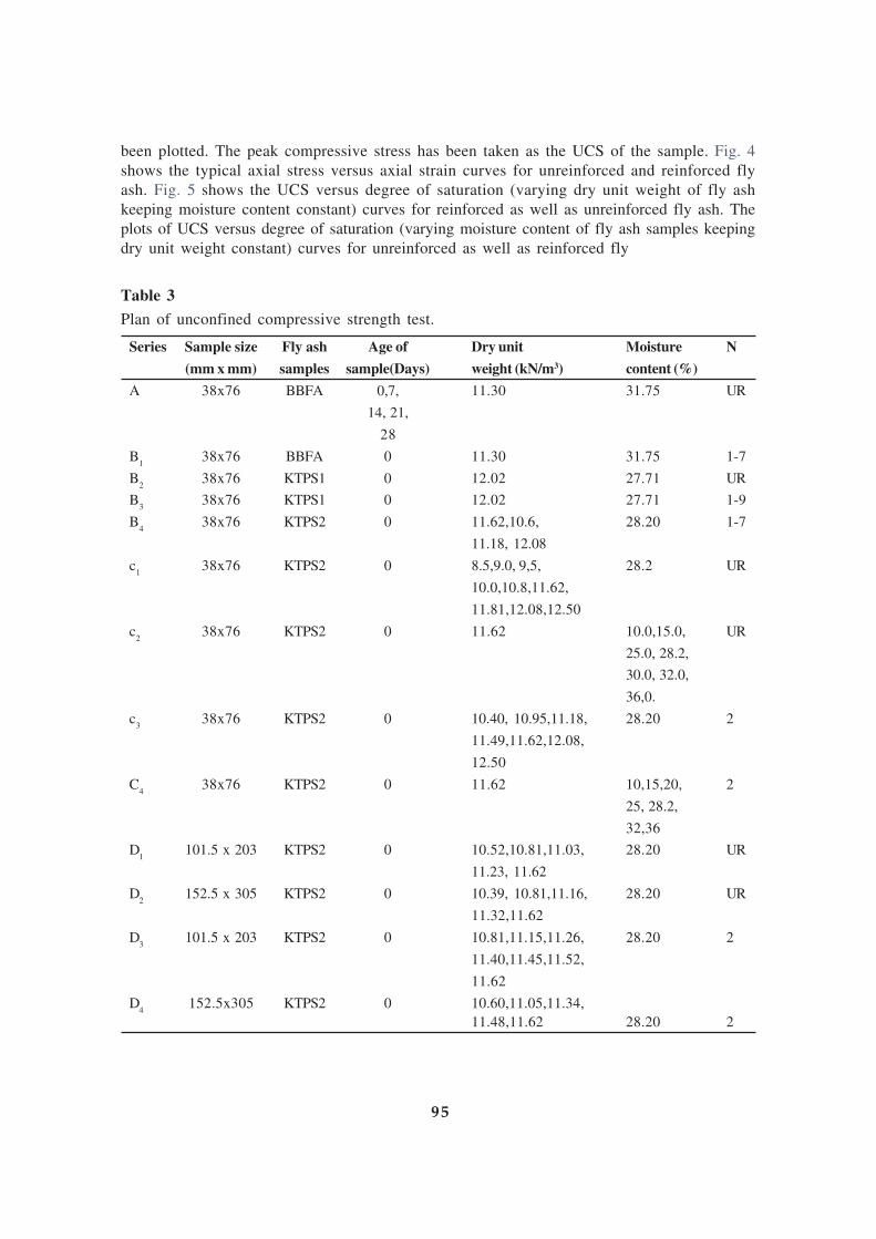
been plotted. The peak compressive stress has been taken as the UCS of the sample. Fig. 4
shows the typical axial stress versus axial strain curves for unreinforced and reinforced fly
ash. Fig. 5 shows the UCS versus degree of saturation (varying dry unit weight of fly ash
keeping moisture content constant) curves for reinforced as well as unreinforced fly ash. The
plots of UCS versus degree of saturation (varying moisture content of fly ash samples keeping
dry unit weight constant) curves for unreinforced as well as reinforced fly
Table 3
Plan of unconfined compressive strength test.
Series Sample size Fly ash Age of Dry unit Moisture N
(mm x mm) samples sample(Days) weight (kN/m3) content (%)
A 38x76 BBFA 0,7, 11.30 31.75 UR
14, 21,
28
B1
38x76 BBFA 0 11.30 31.75 1-7
B2
38x76 KTPS1 0 12.02 27.71 UR
B3
38x76 KTPS1 0 12.02 27.71 1-9
B4
38x76 KTPS2 0 11.62,10.6, 28.20 1-7
11.18, 12.08
c1
38x76 KTPS2 0 8.5,9.0, 9,5, 28.2 UR
10.0,10.8,11.62,
11.81,12.08,12.50
c2
38x76 KTPS2 0 11.62 10.0,15.0, UR
25.0, 28.2,
30.0, 32.0,
36,0.
c3
38x76 KTPS2 0 10.40, 10.95,11.18, 28.20 2
11.49,11.62,12.08,
12.50
C4
38x76 KTPS2 0 11.62 10,15,20, 2
25, 28.2,
32,36
D1
101.5 x 203 KTPS2 0 10.52,10.81,11.03, 28.20 UR
11.23, 11.62
D2
152.5 x 305 KTPS2 0 10.39, 10.81,11.16, 28.20 UR
11.32,11.62
D3
101.5 x 203 KTPS2 0 10.81,11.15,11.26, 28.20 2
11.40,11.45,11.52,
11.62
D4
152.5x305 KTPS2 0 10.60,11.05,11.34,
11.48,11.62 28.20 2
95

Fig. 4. Typical axial stress versus axial strain curves for unreinforced and reinforced
fly ash.
ash are shown in Fig. 6. UCS versus number of layers of reinforcement for varying dry unit
weights of fly ash and also varying types of fly ash are shown in Figs. 7 and 8 respectively.
Fig. 9 shows the plots of UCS versus dry unit weight of fly ash curves with varying specimen
sizes for unreinforced and reinforced fly ash. Effects of age on fly ash samples are shown in
Fig. 10.
Based on the experimental results obtained in this investigation, discussions are made hereunder
highlighting the effects of following parameters on unconfined compressive strength of
reinforced (UCSR) and/or unreinforced (UCSUR) fly ash.
• Degree of saturation
• Sample size
• Number of reinforcement layers
• Age-hardening property of fly ash
Fig. 5 : UCS versus degree of saturation curves with varying dry unit weights.
96

Fig. 6. UCS versus degree of saturation curves with varying moisture contents.
4.1 Effect of degree of saturation on UCS of fly ash specimens
Degree of saturation is one of the vital parameters on unconfined compressive strength of fly
ash samples. Degree of saturation of fly ash samples can be increased either by increasing the
dry unit weight keeping moisture content constant or by increasing the moisture content keeping
dry unit weight constant. Fig. 5 shows the plots of unconfined compressive strength (UCS)
versus degree of saturation (varying dry unit weight of fly ash keeping moisture content
constant) curves for both the unreinforced fly ash samples as well as reinforced (N = 2) fly ash
samples. From Fig. 5 it is found that unconfined compressive strength increases as degree of
saturation increases up to around 75%, and beyond that UCS decreases with further increase
in degree of saturation for both unreinforced and reinforced (N = 2) fly ash. It may be due to
Fig. 7 : UCS versus number of layers of reinforcement (N) for different dry unit weights
of fly ash
97

Fig. 8 : UCS versus number of layers of
reinforcement (N) for different types of
fly ash.
the reason that by increasing dry unit weight at a constant moisture content degree of saturation
increases and in turns both apparent cohesion and compactness between the fly ash particles
increase but after certain degree of saturation apparent cohesion fails rapidly. Fig. 6 shows
the degree of saturation (having constant dry unit weight and varying moisture content) versus
UCS curve for unreinforced as well as reinforced (N = 2) fly ash. From Fig. 6, it is also
observed that UCS of fly ash increases as degree of saturation increases and reaches a peak
value at certain degree of saturation (around 70-75%) beyond that the value of UCS decreases.
It may be due to the reason that with the increase in degree of saturation apparent cohesion
develops in the fly ash samples up to a level of saturation and thereafter the apparent cohesion
so developed starts decreasing. DiGioia and Nuzzo (1972) explained that fly ash exhibits
some apparent cohesion when moist due to surface tension in pore water. McLaren and DiGioia
(1987) reported that the shear strength of class ‘F’ fly ash is primarily dependent on the
cohesion component under partially saturated condition, and when the sample is fully saturated
or dried, it loses its cohesive part of the strength. Misra et al (2003) found that unconfmed
compressive strength of the class C fly ash decreases as moisture content increases in air
curing of samples for 7 days. Present investigation agrees with such observations in case of
fly ash samples used in this experimental work.
4.2 Effect of number of reinforcement layers on UCS of fly ash specimens
Number of layers of reinforcement within a reinforced fly ash structure has an important role
to achieve more advantage in strength, which is one of the main objectives of the present
study. Figs. 7 and 8 show the UCS versus number of layers of jute geo-textiles reinforcement
curves for varying dry unit weights and types of fly ash respectively. From Figs. 7 and 8, it is
found that UCS increases up to 5 layers of reinforcement as number of layer of reinforcement
increases after that the increase in UCS is negligible or almost zero. It is also noticed that the
rate of increase in UCS is maximum up to 4th layer of reinforcement. The improvement of
UCS for reinforced sample over unreinforced case may be expressed with the following
equation:
R URf
UR
UCS UCSI
UCS
−=
..... (1)
Fig. 9 : UCS versus dry unit weight curves with
varying specimen sizes for unreinforced and
reinforced (N = 2) fly ash (KTPS2)
98

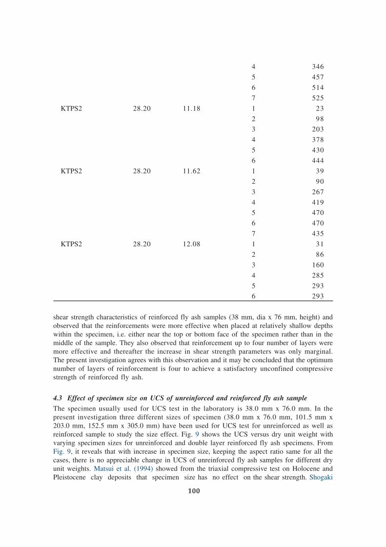
Table 4 presents the values of If , wherefrom it is observed that the rate of improvement,
(If(N+1)
–If(N)
) is maximum 3rd layers to 4th layers of reinforcement for all three types of fly
ash samples viz., BBFA (γ d = 11.30 kN/m3), KTPS1 (γd= 12.02 kN/m3), and KTPS2 (γ
d =
10-6, 11.18, and 12.08 kN/m3). From Table 4, it is also noticed that in case of KTPS2 fly
ash sample, the maximum improvement has been found for lower density (10.6 kN/m3)
and corresponding value of If is around 525%. Choudhary and Verma (2003) studied the
Fig. 10 : UCS versus age of samples of fly ash
Table 4
Values of If
Fly ash samples w(%) γγγγγ d(kN/m3) N If(%)
BBFA 31.75 11.30 1 60
2 135
3 217
4 392
5 405
6 414
7 448
KTPS1 27.71 12.02 1 54
2 68
3 92
4 164
5 199
6 204
7 208
KTPS2 28.20 10.60 1 24
2 71
3 163
99
4 346
5 457
6 514
7 525
KTPS2 28.20 11.18 1 23
2 98
3 203
4 378
5 430
6 444
KTPS2 28.20 11.62 1 39
2 90
3 267
4 419
5 470
6 470
7 435
KTPS2 28.20 12.08 1 31
2 86
3 160
4 285
5 293
6 293
shear strength characteristics of reinforced fly ash samples (38 mm, dia x 76 mm, height) and
observed that the reinforcements were more effective when placed at relatively shallow depths
within the specimen, i.e. either near the top or bottom face of the specimen rather than in the
middle of the sample. They also observed that reinforcement up to four number of layers were
more effective and thereafter the increase in shear strength parameters was only marginal.
The present investigation agrees with this observation and it may be concluded that the optimum
number of layers of reinforcement is four to achieve a satisfactory unconfined compressive
strength of reinforced fly ash.
4.3 Effect of specimen size on UCS of unreinforced and reinforced fly ash sample
The specimen usually used for UCS test in the laboratory is 38.0 mm x 76.0 mm. In the
present investigation three different sizes of specimen (38.0 mm x 76.0 mm, 101.5 mm x
203.0 mm, 152.5 mm x 305.0 mm) have been used for UCS test for unreinforced as well as
reinforced sample to study the size effect. Fig. 9 shows the UCS versus dry unit weight with
varying specimen sizes for unreinforced and double layer reinforced fly ash specimens. From
Fig. 9, it reveals that with increase in specimen size, keeping the aspect ratio same for all the
cases, there is no appreciable change in UCS of unreinforced fly ash samples for different dry
unit weights. Matsui et al. (1994) showed from the triaxial compressive test on Holocene and
Pleistocene clay deposits that specimen size has no effect on the shear strength. Shogaki
100

(2007) also reported that there was no difference in shear strength and deformation
characteristics between the small (15 mm x 35 mm) and ordinary specimens (35 mm x 80
mm) and between the specimens for soils having plasticity ranges from 10 to 370 and
unconfined compressive strength of 18 kPa to 1000 kPa, that were taken from 26 different
sites in the United Kingdom, Korea and Japan. From Fig. 9 it is found that the values of UCS
increase for different unit weights as the specimen size increases in case of reinforced fly ash
(N = 2). It may be due to the reason that for the sample of higher diameter, area of interface
friction increases and hence higher UCS is achieved for reinforced fly ash. Haeri et al. (2000)
have also found the similar effect in triaxial compressive tests of geotextile-reinforced sand.
4.4. Age-hardening property on UCS of fly ash
In the present investigation, the effect of age-hardening property of Budge Budge fly ash
(BBFA) has been studied on unreinforced samples by keeping them in air-tight desiccators
for 7,14,21, and 28 days after preparation of samples at optimum moisture content and
maximum dry unit weight condition. Fig. 10 represents the relationship between UCS and age
of sample. From the figure, it is found that unconfined compressive strength of unreinforced
fly ash increases with age under moist condition. Strength increases about 75% at 28 days,
whereas 45% increase in strength is achieved within 7 days of preparation. However, strength
development is continued even after 21 days. Misra et al. (2003) found the similar behaviour
during unconfined compressive test of stabilized clay soils-fly ash blend.
5. Numerical model for predicting UCSUR
Unconfined compressive strength of reinforced fly ash depends on a number of factors viz.,
specific gravity, grain size distribution, degree of saturation, method of compaction, types of
fly ash, types of reinforcement, number of layers of reinforcement, and vertical spacing between
adjacent reinforcement layers. Fly ash collected from thermal power plant shows a wide range
of variation of engineering properties (Pandian, 2004; Capco, 1990). Due to the wide variation
of these properties, it is difficult and also laborious to determine UCS of reinforced fly ash
considering all the factors together. Kaniraj and Havanagi (2001) have developed a
mathematical model to estimate relative gain in unconfined compressive strength (Gf) of fibre-
reinforced specimens in terms of UCS of unreinforced fly ash. Ghosh and Subbarao (2006)
proposed simple power models to estimate
the Brazilian tensile strength, flexural
strength, bearing ratio, and slake durability
indices from unconfined compressive test
results of class F fly ash stabilized with
lime and gypsum. Based on the
experimental results of the present
investigation, an attempt has been made
to develop an empirical model to predict
the unconfined compressive strength of
reinforced fly ash in terms of UCS of
unreinforced fly ash and number of layers
of reinforcement. Multiple regression
(parametric) analysis has been performed
to develop this model. The details of the
multiple regression methods are presented
elsewhere (Bera et al, 2005). From 44
numbers of data points, a non-linear power
model has been developed to predict theFig. 11 : Predicted UCSUR
versus observed UCSR curve.
101
unconfined compressive strength (UCSR) of reinforced fly ash in terms of unconfined
compressive strength (UCSUR) of unreinforced fly ash and number (N) of layers of
reinforcement. The power model, so developed, is as follows:
UCSR = 5.3554(UCS
UR)0.7017(N)0.6804 ........(2)
where UCSR = unconfined compressive strength of reinforced fly ash in kPa, UCSUR =
unconfined compressive strength of unreinforced fly ash in kPa, N= number of layers of jute
geotextiles.
Fig. 11 shows the predicted values of UCSR versus observed values of UCSR from Eq. (2). For
checking the efficiency of the model the relevant statistical coefficient like coefficient of
determination (R2) and estimated standard error (Se) have been determined and the respective
values are found to be 0.867 and 0.099.
Significance of the multiple regression coefficient as a whole of the Eq. (2) has been tested
using the ‘F’ statistics and the significance of the partial multiple regression co-efficients of
Eq. (2) has been performed through the ‘t’ statistics. The calculated values of F (FCal
) has been
found to be 134. From the table of F (Draper and Smith, 1966) distribution with level of
significance, α = 0.05, F(0.95, 2, 41) = 3.226. Therefore, Fcal
= l34> the tabulated F (0.95, 2,
41) = 3.226. Similarly the calculated values of t statistics (tcal
) for intercept, UCSUR
, and also N
are 4.645, 8.989, and 12.887 respectively whereas tabulated t statistics i.e. t(41, 0.975)
= 2.01.
From comparison of the tabulated and calculated values, it is opined that the results of the
tests are satisfactory.
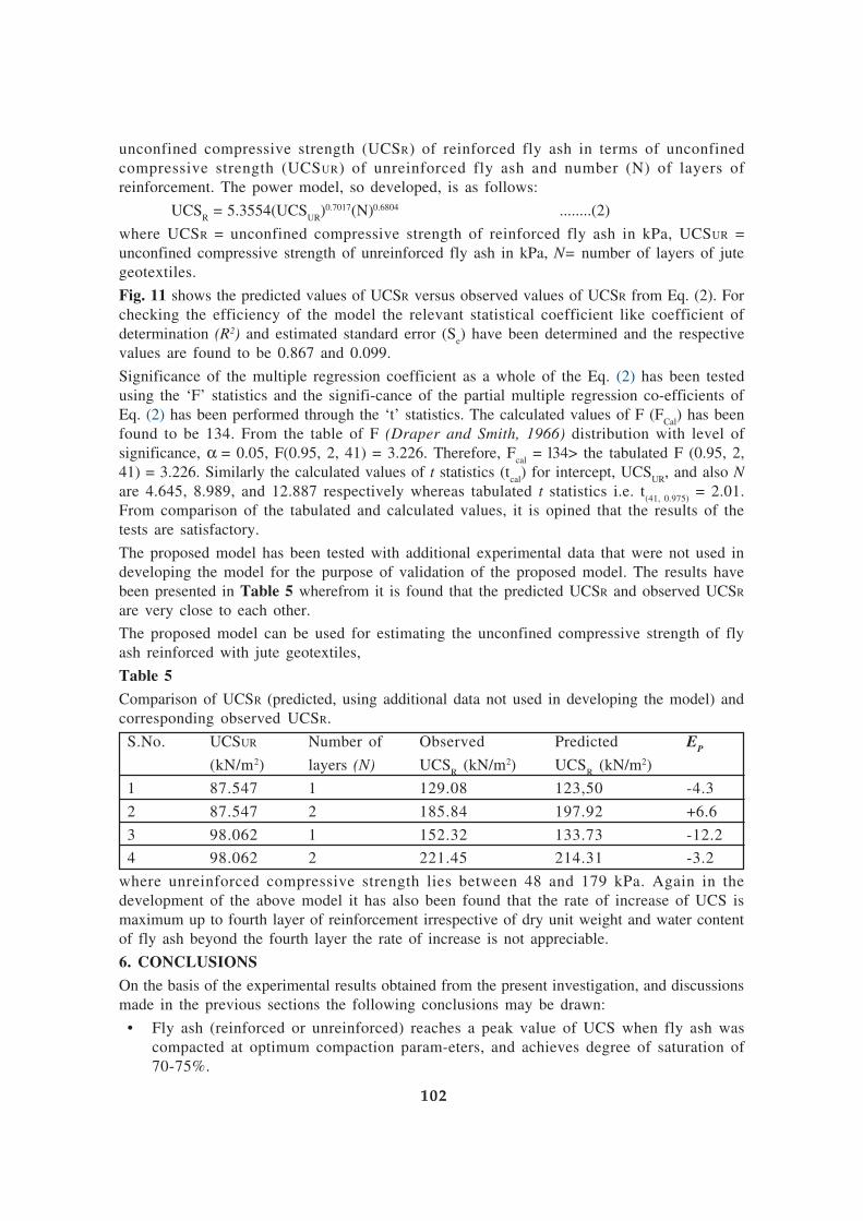
The proposed model has been tested with additional experimental data that were not used in
developing the model for the purpose of validation of the proposed model. The results have
been presented in Table 5 wherefrom it is found that the predicted UCSR and observed UCSR
are very close to each other.
The proposed model can be used for estimating the unconfined compressive strength of fly
ash reinforced with jute geotextiles,
Table 5
Comparison of UCSR (predicted, using additional data not used in developing the model) and
corresponding observed UCSR.
S.No. UCSUR Number of Observed Predicted EP
(kN/m2) layers (N) UCSR (kN/m2) UCS
R (kN/m2)
1 87.547 1 129.08 123,50 -4.3
2 87.547 2 185.84 197.92 +6.6
3 98.062 1 152.32 133.73 -12.2
4 98.062 2 221.45 214.31 -3.2
where unreinforced compressive strength lies between 48 and 179 kPa. Again in the
development of the above model it has also been found that the rate of increase of UCS is
maximum up to fourth layer of reinforcement irrespective of dry unit weight and water content
of fly ash beyond the fourth layer the rate of increase is not appreciable.
6. CONCLUSIONS
On the basis of the experimental results obtained from the present investigation, and discussions
made in the previous sections the following conclusions may be drawn:
• Fly ash (reinforced or unreinforced) reaches a peak value of UCS when fly ash was
compacted at optimum compaction parameters, and achieves degree of saturation of
70-75%.
102

• The effect of specimen size on UCS is negligible in case of unreinforced fly ash.
• The effect of specimen size on UCS is appreciable for reinforced fly ash sample. With
increase in diameter of the double layer jute geotextiles reinforced sample from 38 mm
to 152.5 mm, the UCS increases.
• Inclusion of jute geotextiles within the specimen as reinforcement enhances the peak
value of UCS. This progress is more effective with a higher number of jute geotextiles
reinforcement layers. But it is effective up to four layers of reinforcement and beyond
that it is marginal.
• The improvement of UCS is maximum for low dry unit weight reinforced fly ash and
maximum improvement was achieved around 525% in case of KTPS2 fly ash at OMC
and dry unit weight of 10.60 kN/m3.
• The percentage increase in UCS of reinforced fly ash is more in between 3 and 4 layers
of reinforcement.
• Compacted unreinforced Budge Budge fly ash (BBFA) exhibits increase in strength after
7 days to be 45% and up to 75% increase at 28 days when the samples were kept in air-
tight desiccators.
• A simple non-linear regression power model proposed herein may be used to estimate
the unconfined compressive strength of jute geotextile-reinforced fly ash (UCSR) from
the UCS test results of unreinforced fly ash (UCSUR) and number of layers of reinforcement
(N).
• The proposed model is applicable when the result of UCS of unreinforced fly ash and the
number of layers of reinforcement lie within the range of 48-179 kPa and 1-4 respectively.
REFERENCES
ASTM D 2487,1992. Classification of soils for engineering purposes. Philadelphia, PA, pp. 56-65.
ASTM D 2166, 1985. Test method for unconfined compressive strength of soil. Philadelphia.
ASTM D 698, 1991. Test method for laboratory compaction characteristics of soil using standard effort.
Philadelphia, PA, pp. 28-35.
Bera, A.K., Ghosh, A., Ghosh, A., 2005. Regression model for bearing capacity of a square footing on reinforced
pond ash. Geotextiles and Geomembranes 23 (3),261-285.
Bera, A.K., Ghosh, A., Ghosh, A., 2007. Compaction characteristics of pond ash. Journal of Materials in Civil
Engineering Division, ASCE 19 (4), 349-357.
Capco, 1990. Pulverized fuel ash as a reclamation fills. Report, China Light and Power Co. Ltd., Hong Kong,
pp. 1-34.
Chauhan, M.S., Mittal, S., Mohanty, B., 2008. Performance evaluation of silty sand subgrade reinforced with
fly ash and fibre. Geotextiles and Geomembranes 26 (5), 429-435.
Choudhary, A.K., Verma, P.B., 2003. Shear strength characteristics of reinforced fly ash. IGC, Roorkee, Dec
18-20.
DiGioia, A.M., Nuzzo, Wl., 1972. Fly ash as structural fill, journal of Power Division, ASCE 98 (1), 77-92.
Draper, N.R., Smith, H., 1966. Applied Regression Analysis. John Wiley and Sons, New York.
Glogowski, RE., Kelly, J.M., McLaren, R.J., Burns, D.L, 1992. Fly ash design manual for road and site
applications. RP2422-2, Prepared for Electric Power Research Institute, GAI Consultants. Inc., PA.
Gray, D.H., Lin, Y.K., 1972. Engineering properties of compacted fly ash. Journal of Soil Mechanics and
Foundations Divisions, ASCE 98 (4), 361-380.
Gandhi, S.R., Dey, A.K., Selvam, S., 1999. Densification of pond ash by blasting. Journal of Geotechnical and
Geoenvironmental Engineering, ASCE 125 (10), 889-899.
103

Ghosh, A., Subbarao, C, 2006. Tensile strength bearing ratio and slake durability of class F fly ash stabilized
with lime and gypsum. Materials in Civil Engineering Division, ASCE 18(1), 18-27.
Ghosh, A., Subbarao, C, 2007. Strength characteristics of class F fly ash modified with lime and gypsum.
Journal of Geotechnical and Geoenvironment Engineering 133 (7), 757-766.
Haeri, S.N., Noorzad, R., Oskoorouchi, A.M., 2000. Effect of geotextile reinforcement on the mechanical
behaviour of sand. Geotextiles and Geomembranes 18 (6), 385-402.
Indian Standards, IS: 1727, 1967. Methods of test for pozzolanic materials. New Delhi, India.
Kamei, T., Tokida, M., 1991. Influence on specimen size on unconfined compressive strength and deformation
characteristics of cohesive soils. Proceedings of 45th Annual Conference JSCE, No. 436, IH-16, pp. 131-
134. (in Japanese).
Kaniraj, S.R., Gayathri, V., 2004. Permeability and consolidation characteristics of compacted fly ash. Journal
of Energy Engineering, ASCE 130 (1), 18-43.
Kaniraj, S.R., Havanagi, V.G., July 2001. Behavior of cement-stabilized fiber-reinforced fly ash-soil mixtures.
Journal of Geotechnical and Geoenvironmental Engineering, ASCE 127 (7).
Kim, Y.T., Kim, H.J., Lee, G.H., 2008. Mechanical behaviour of lightweight soil reinforced with waste
fishing net. Geotextiles and Geomembranes 26 (6), 512-518.
Leonards, G.A., Bailey, B., 1982. Pulverized coal ash as structural fill. Journal of Geotechnical Engineering
Division, ASCE 108 (4), 517-531.
Matsui, T., Oda, K., Nabeshima, Y., 1994. Development and applications for natural deposits of minimum
triaxial compression apparatus. Tsuchi to Kiso 42 (11), 17-22 (In Japanese).
McLaren, R.J„ DiGioia, A.M., 1987. The typical engineering properties of fly ash. In: Wood, R.D. (Ed.),
Proceedings of Conference on Geotechnical Practice for Waste Disposal. Geotechnical special publication
No. 13, ASCE, New York, pp. 683-697.
Misra, A., Upadhyaya, S., Biswas, D., 2003. Utilization of silo stored and ponded class C fly ash in road bases.International Ash Utilization Symposium, Center for Applied Energy Research, University of Kentucky,
paper 118.
Pandian N.S., 2004. Fly ash characterization with reference to geotechnical applications. Journal of Indian
Institute Science, India. Nov-Dec, pp. 189-216.
Park, S.S., 2009. Effect of fiber reinforcement and distribution on unconfined compressive strength of fiber-
reinforced cemented sand. Geotextiles and Geomembranes 27 (2), 162-166.
Ranganathan, S.R., 1994. Development and potential of jute geotextiles. Geotextiles and Geomembranes 13,
421-433,
Rawal, A., Anandjiwala, R„ 2007. Comparative study between needlepunched nonwoven geotextile structures
made from flax and polyester fibres. Geotextiles and Geomembranes 25 (1), 61-65.
Raymond, S., 1958. Utilization of pulverized fuel ash. Civil Engineering and Public Works Review, London,
vol. 53, pp. 1013-1016.
Sarsby, R.W., 2007. Use of’Limited Life Geotextiles’ (LLCs) for basal reinforcement of embankments built
on soft clay. Geotextiles and Geomembranes 25 (4-5), 302-310.
Seals, R.K., Moulton, L.K., Ruth, B.E., 1972. Bottom ash: an engineering material. Journal of Soil Mechanics
and Foundations Division, ASCE 98 (4), 311-325.
Shogaki, T.t 2007. Effect of specimen size on unconfined compressive strength properties of natural deposits.
Soils and Foundations 47 (1), 119-129.
Subaida, E.A., Chandrakaran, S., Sankar, N., 2008. Experimental investigations on tensile and pullout
behaviour of woven coir geotextiles. Geotextiles and Geomembranes 26 (5) 384-39.
Subbarao, C, Ghosh, A., 1997. Fly ash management by stabilization. Journal of Solid Waste Technology and
Management 24 (3), 126-130.
Tang, C, Shi, B., Gao, W., Chen, E, Cai, Y, 2007. Strength and mechanical behaviour of short polypropylene
and cement stabilized clayey soil. Geotextiles and Geomembranes 25 (3), 194-202.
104

A LABORATORY STUDY ON GEOJUTE
REINFORCED SOIL BED UNDER CYCLIC LOADING
R. B. Sahu, H. K. Hazra, N. Som
ABSTRACT :
Model footing tests were carried out under cyclic loading in order to evaluate aging effect on
behaviour of geojute reinforced soil bed along with biodegradation of JGT with time. Both
total and permanent settlement of footings were found to reduce with aging of soil under
various load cycle. Increase in cohesion and reduction in moisture content were found to
increase with increasing aging period of test bed. Overall performance of test bed was found
to improve with aging of soil even after complete biodegradation of geojute.
1. INTRODUCTION
Geojute (JGT) fabric has been used as a substitute of synthetic geotextile in construction of
low to medium volume roads to enhance their performance. Ramaswamy and Aziz (1989)
first highlighted suitability of geojute fabric in construction of roads through a series of
laboratory tests on JGT-soft subgrade system. JGT was found to reduce the rut depth by 45%.
Mandal et. al (2003) reported 35% reduction in permanent deformation due to the inclusion
of JGT at the interface of gravel subbase and the subgrade. Rao et. al. (1996) reported that
tensile strength of JGT embedded in soil would be negligible after 3-4 months. Rao et. al
(2003) reported successful performance of an embankment over soft clay with JGT as a
reinforcing layer at the base of the’ embankment. Increase in strength of the underlying soft
clay was found to make the embankment stable after JGT lost its tensile strength. A case
study was also reported by Rao (2003) to show improvement in properties of soft subgrade
below pavement with time.
From the above studies it appears that overall change of JGT reinforced pavement may improve
its performance in spite of reduction in tensile strength of JGT. This paper presents the effect
of aging on the improvement in settlement characteristics of JGT reinforced unpaved road
and strength of soft subgrade under cyclic loading with geojute (JGT) at the interface of the
subgrade and granular fill through a series of model footing tests.
2. OBJECTIVES
a) To determine reduction in permanent deformation for reinforced soil bed with aging
under cyclic loading
b) To determine increase in cohesion and reduction in moisture content of the subgrade
under cyclic loading for reinforced soil bed
3. EXPERIMENTAL WORK
Three series of tests were done to assess the behaviour of unpaved road with the inclusion of
JGT at the interface of soft subgrade and top fill. These are –
* Series A (WOJGT) - No JGT at the interface of fill and clay
* Series B (WJGT) - JGT at the interface of fill and clay. Tests done immediately after
preparation of soil bed
105

* Series C (WJGTA) - JGT at the interface of fill and clay. Tests done 2, 4 and 6 months
after preparation of soil bed
Series A and B tests were done to study the improvement in behaviour of soil bed with the
inclusion of JGT while Series C was done to assess the aging effect on the behaviour of
reinforced bed. These tests were performed in order to assess overall performance of reinforced
bed due to biodegradation of JGT and change in soil characteristics that may occur with time.
A schematic diagram of the test set up is presented in Fig. 1. Soft subgrade was prepared by
artificially consolidating natural clay in layers under a pressure of 60 kN/m2 for three days.
Thickness of the consolidated bed was 400+10mm.
Properties of clay :
Liquid Limit : 57%
Plastic Limit : 27%
Grain Size Distributor :
Sand : 6%
Silt : 40%
Clay : 54%
Average cohesion of artificially consolidated soil bed is 21 kN/m2. This was determined from
vane shear tests. After preparing the soil bed a layer of JGT was placed over it. Over this a
50mm thick compacted sand bed was laid.
Properties of Geojute (JGT) :
Type : Woven
Weight : 760gsm
Tensile strength : 20 kN/m
106
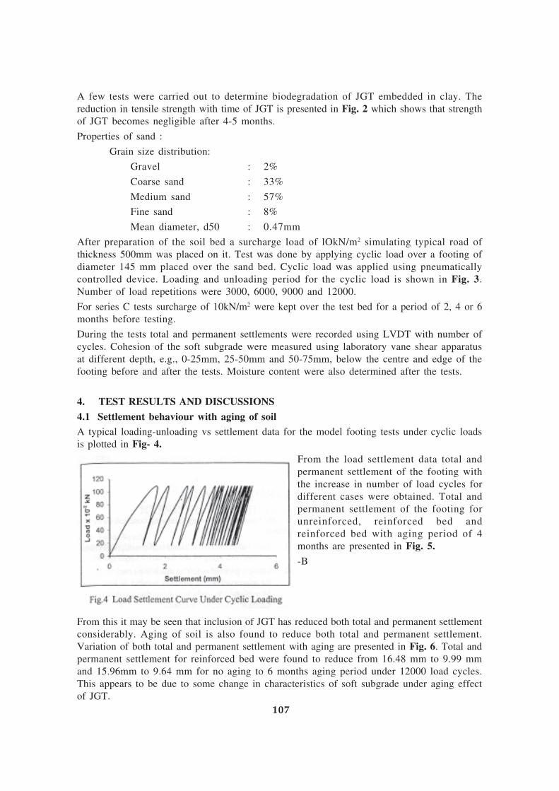
A few tests were carried out to determine biodegradation of JGT embedded in clay. The
reduction in tensile strength with time of JGT is presented in Fig. 2 which shows that strength
of JGT becomes negligible after 4-5 months.
Properties of sand :
Grain size distribution:
Gravel : 2%
Coarse sand : 33%
Medium sand : 57%
Fine sand : 8%
Mean diameter, d50 : 0.47mm
After preparation of the soil bed a surcharge load of lOkN/m2 simulating typical road of
thickness 500mm was placed on it. Test was done by applying cyclic load over a footing of
diameter 145 mm placed over the sand bed. Cyclic load was applied using pneumatically
controlled device. Loading and unloading period for the cyclic load is shown in Fig. 3.
Number of load repetitions were 3000, 6000, 9000 and 12000.
For series C tests surcharge of 10kN/m2 were kept over the test bed for a period of 2, 4 or 6
months before testing.
During the tests total and permanent settlements were recorded using LVDT with number of
cycles. Cohesion of the soft subgrade were measured using laboratory vane shear apparatus
at different depth, e.g., 0-25mm, 25-50mm and 50-75mm, below the centre and edge of the
footing before and after the tests. Moisture content were also determined after the tests.
4. TEST RESULTS AND DISCUSSIONS
4.1 Settlement behaviour with aging of soil
A typical loading-unloading vs settlement data for the model footing tests under cyclic loads
is plotted in Fig- 4.
From the load settlement data total and
permanent settlement of the footing with
the increase in number of load cycles for
different cases were obtained. Total and
permanent settlement of the footing for
unreinforced, reinforced bed and
reinforced bed with aging period of 4
months are presented in Fig. 5.
-B
From this it may be seen that inclusion of JGT has reduced both total and permanent settlement
considerably. Aging of soil is also found to reduce both total and permanent settlement.
Variation of both total and permanent settlement with aging are presented in Fig. 6. Total and
permanent settlement for reinforced bed were found to reduce from 16.48 mm to 9.99 mm
and 15.96mm to 9.64 mm for no aging to 6 months aging period under 12000 load cycles.
This appears to be due to some change in characteristics of soft subgrade under aging effect
of JGT.
107
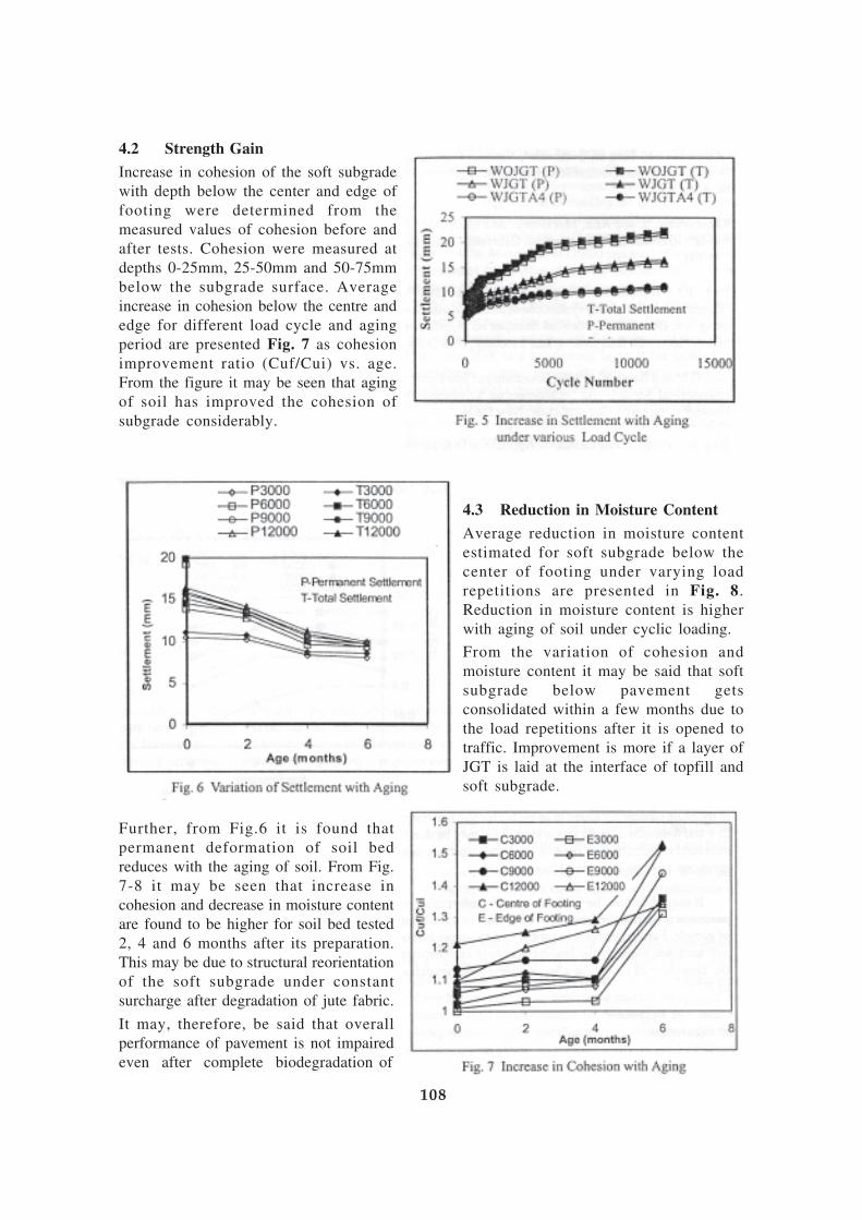
4.2 Strength Gain
Increase in cohesion of the soft subgrade
with depth below the center and edge of
footing were determined from the
measured values of cohesion before and
after tests. Cohesion were measured at
depths 0-25mm, 25-50mm and 50-75mm
below the subgrade surface. Average
increase in cohesion below the centre and
edge for different load cycle and aging
period are presented Fig. 7 as cohesion
improvement ratio (Cuf/Cui) vs. age.
From the figure it may be seen that aging
of soil has improved the cohesion of
subgrade considerably.
4.3 Reduction in Moisture Content
Average reduction in moisture content
estimated for soft subgrade below the
center of footing under varying load
repetitions are presented in Fig. 8.
Reduction in moisture content is higher
with aging of soil under cyclic loading.
From the variation of cohesion and
moisture content it may be said that soft
subgrade below pavement gets
consolidated within a few months due to
the load repetitions after it is opened to
traffic. Improvement is more if a layer of
JGT is laid at the interface of topfill and
soft subgrade.
Further, from Fig.6 it is found that
permanent deformation of soil bed
reduces with the aging of soil. From Fig.
7-8 it may be seen that increase in
cohesion and decrease in moisture content
are found to be higher for soil bed tested
2, 4 and 6 months after its preparation.
This may be due to structural reorientation
of the soft subgrade under constant
surcharge after degradation of jute fabric.
It may, therefore, be said that overall
performance of pavement is not impaired
even after complete biodegradation of
108

geojute. Further, increase in cohesion of the
upper part of soft subgrade under cyclic
loading may help in enhancing the
behaviour of pavement after complete
biodegradation of JGT.
5. CONCLUSIONS
On the basis of above study following
conclusions may be drawn:
1. Total and permanent settlement of a
reinforced soil bed reduces with aging
of soil for various load cycles.
2. Strength gain and reduction in moisture
content is higher for reinforced bed at
different number of load cycles.
Strength gain and reduction in moisture content becomes higher with aging of test bed.
3. Aging of soil improves the overall performance of reinforced bed in spite of reduction in
tensile strength of JGT.
REFERENCES
Mandal, J.N., Kamat, D.S. and Nimbalkar, S.S. (2003), “Repeated Load Tests on Geotextile”, National
Seminar on ‘Application of Jute Geotextile &Innovative Jute Products’, New Delhi.
Ramaswamy, S. and Aziz, M. (1989), “Jute Geotextile for Roads”, International Workshops on
Geotextile, India, pp. 137-143.
Rao, P.J., Bindumadhava and Vensiri, M. (2003), “Construction of Highway Embankment on Soft
Marine Soil using Jute Geotextiles”, National Seminar on ‘Application of Jute Geotextile &Innovative Jute
Products’, New Delhi.
Rao, GV. and Balan, K. (1996), “Durability of Jute Fabric”, International Seminar and Technomeet on
‘Environmental Geotechnology with Geosynthetics’, New Delhi.
Rao, A. S. (2003), “Jute Geotextile Application in Kakinada Port Area”, National Seminar on ‘Application
of Jute Geotextile &Innovative Jute Products’, New Delhi.
109

CARBON FOOT-PRINT REDUCTION IN ROAD
CONSTRUCTION – A CASE FOR JUTE GEOTEXTILESTapobrata Sanyal
1 INTRODUCTION
The problem of GHG emissions in making road construction materials has of late attracted
the attention of highway engineers prompting intensive search for and study on environment-
friendly innovative alternatives. The concern for environmental pollution as a result of unabated
use of by-products of fossil fuel and mining of stones in road construction has led to gradual
shift from conventional materials in road construction to innovative less polluting construction-
ingredients. Adoption of materials and techniques that can reduce the quantity of polluting
materials should be the appropriate approach. It will not be possible to eliminate the carbon
foot print in road construction completely but ways need be found to lower it without
compromising with the essential technical requirements and the desired quality. This will
necessitate attempts to use such a material would need to address two pre-requisites viz., a)
eco-sustainability of the material established through LCA (Life Cycle Assessment) of the
material and b) suitability of the material in road construction.
Jute Geotextiles (JGT) which has been applied in road constructions (other than NHs in
India) in India with success could be worth trying in this context. Jute is a renewable natural
resource and eco-compatible.
This paper puts forward a case for JGT in road construction in the context of reduction of
GHG emissions.
2. ABOUT JUTE & JUTE GEOTEXTILES (JGT)
Jute Geotextiles (JGT) are natural geosynthetics under GEOTECH category of technical textiles.
The fabric is manufactured from jute yarns after extracting the bast fibres of the plant of the
same name through retting and processing the extracted fibres to make yarns. Jute fibres are
essentially lingo-cellulosic in character.
Table 1 Table 2
Chemical Constituents of Jute Fibre Properties of Jute Fibre
Constituents %
Cellulose 60 – 62
Hemi-Cellulose 22 - 24
Lignin 12 – 14
Others 1 – 2
Specific gravity (gm/cc) 1.48
Co-efficient of static friction 0.45-0.54
Swelling in Water (Area wise) 40%
Water retention 70 %
Refractive Index 1.577
Specific Heat (cal/g/° C) 0.324
Thermal conductivity
(cal/sec/cm.° C/cm2) 0.91x 10⁻⁴
Thermal Conductivity
(M watt/metre.kelvin) 427.3
Heat of Combustion (Jules/g) 17.5
Ignition temperature (°C) 193
110
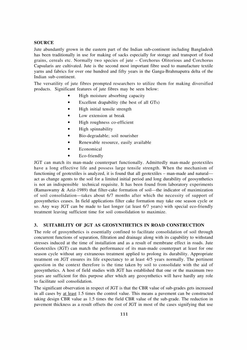
SOURCE
Jute abundantly grown in the eastern part of the Indian sub-continent including Bangladesh
has been traditionally in use for making of sacks especially for storage and transport of food
grains, cereals etc. Normally two species of jute – Corchorus Olitorious and Corchorus
Capsularis are cultivated. Jute is the second most important fibre used to manufacture textile
yarns and fabrics for over one hundred and fifty years in the Ganga-Brahmaputra delta of the
Indian sub-continent.
The versatility of jute fibres prompted researchers to utilize them for making diversified
products. Significant features of jute fibres may be seen below:
• High moisture absorbing capacity
• Excellent drapability (the best of all GTs)
• High initial tensile strength
• Low extension at break
• High roughness co-efficient
• High spinnability
• Bio-degradable; soil nourisher
• Renewable resource, easily available
• Economical
• Eco-friendly
JGT can match its man-made counterpart functionally. Admittedly man-made geotextiles
have a long effective life and possess large tensile strength. When the mechanism of
functioning of geotextiles is analyzed, it is found that all geotextiles – man-made and natural—
act as change agents to the soil for a limited initial period and long durability of geosynthetics
is not an indispensible technical requisite. It has been found from laboratory experiments
(Ramaswamy & Aziz-1989) that filter-cake formation of soil—the indicator of maximization
of soil consolidation—takes about 6/7 months after which the necessity of support of
geosynthetics ceases. In field applications filter cake formation may take one season cycle or
so. Any way JGT can be made to last longer (at least 6/7 years) with special eco-friendly
treatment leaving sufficient time for soil consolidation to maximize.
3. SUITABILITY OF JGT AS GEOSYNTHETICS IN ROAD CONSTRUCTION
The role of geosynthetics is essentially confined to facilitate consolidation of soil through
concurrent functions of separation, filtration and drainage along with its capability to withstand
stresses induced at the time of installation and as a result of membrane effect in roads. Jute
Geotextiles (JGT) can match the performance of its man-made counterpart at least for one
season cycle without any extraneous treatment applied to prolong its durability. Appropriate
treatment on JGT ensures its life expectancy to at least 4/5 years normally. The pertinent
question in the context therefore is the time taken by soil to consolidate with the aid of
geosynthetics. A host of field studies with JGT has established that one or the maximum two
years are sufficient for this purpose after which any geosynthetics will have hardly any role
to facilitate soil consolidation.
The significant observation in respect of JGT is that the CBR value of sub-grades gets increased
in all cases by at least 1.5 times the control value. This means a pavement can be constructed
taking design CBR value as 1.5 times the field CBR value of the sub-grade. The reduction in
pavement thickness as a result offsets the cost of JGT in most of the cases signifying that use
111
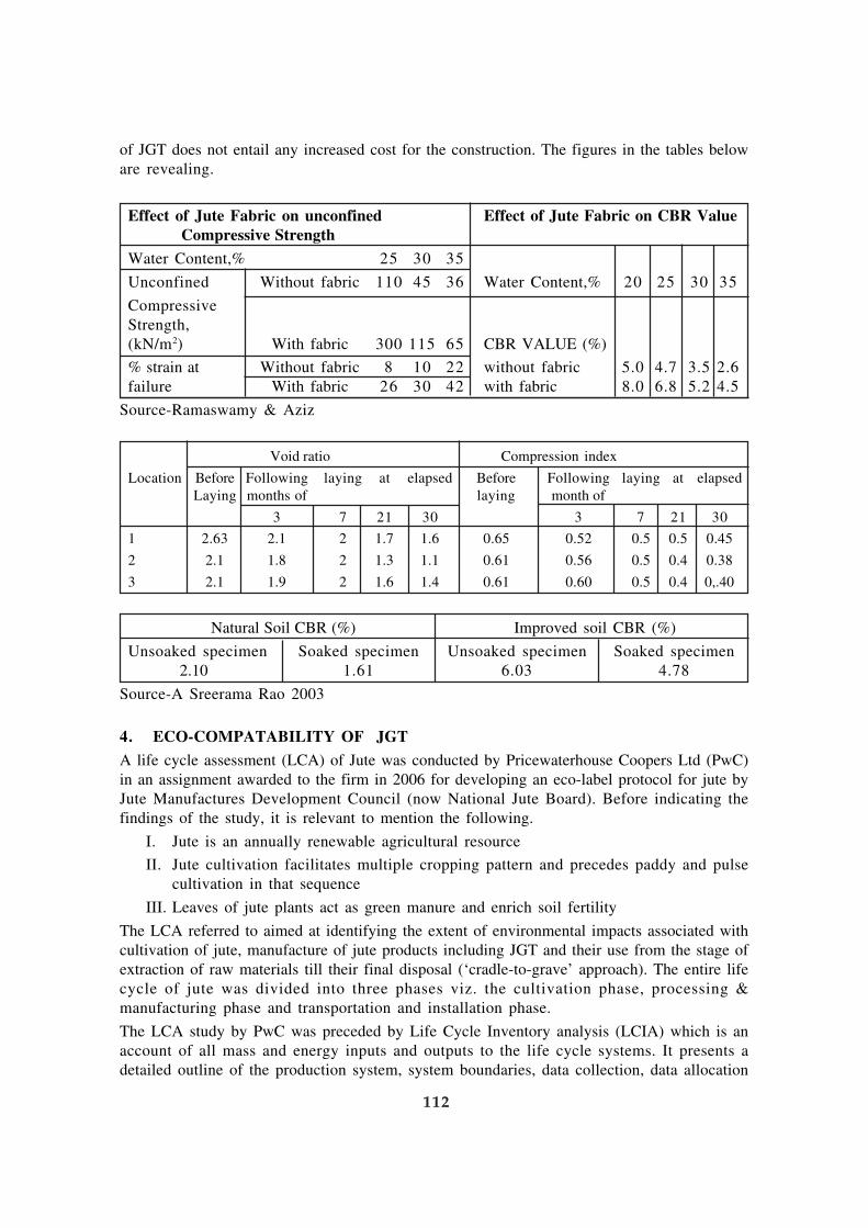
of JGT does not entail any increased cost for the construction. The figures in the tables below
are revealing.
Effect of Jute Fabric on unconfined Effect of Jute Fabric on CBR Value
Compressive Strength
Water Content,% 25 30 35
Unconfined Without fabric 110 45 36 Water Content,% 20 25 30 35
Compressive
Strength,
(kN/m2) With fabric 300 115 65 CBR VALUE (%)
% strain at Without fabric 8 10 22 without fabric 5.0 4.7 3.5 2.6
failure With fabric 26 30 42 with fabric 8.0 6.8 5.2 4.5
Source-Ramaswamy & Aziz
Void ratio Compression index
Location Before Following laying at elapsed Before Following laying at elapsed
Laying months of laying month of
3 7 21 30 3 7 21 30
1 2.63 2.1 2 1.7 1.6 0.65 0.52 0.5 0.5 0.45
2 2.1 1.8 2 1.3 1.1 0.61 0.56 0.5 0.4 0.38
3 2.1 1.9 2 1.6 1.4 0.61 0.60 0.5 0.4 0,.40
Natural Soil CBR (%) Improved soil CBR (%)
Unsoaked specimen Soaked specimen Unsoaked specimen Soaked specimen
2.10 1.61 6.03 4.78
Source-A Sreerama Rao 2003
4. ECO-COMPATABILITY OF JGT
A life cycle assessment (LCA) of Jute was conducted by Pricewaterhouse Coopers Ltd (PwC)
in an assignment awarded to the firm in 2006 for developing an eco-label protocol for jute by
Jute Manufactures Development Council (now National Jute Board). Before indicating the
findings of the study, it is relevant to mention the following.
I. Jute is an annually renewable agricultural resource
II. Jute cultivation facilitates multiple cropping pattern and precedes paddy and pulse
cultivation in that sequence
III. Leaves of jute plants act as green manure and enrich soil fertility
The LCA referred to aimed at identifying the extent of environmental impacts associated with
cultivation of jute, manufacture of jute products including JGT and their use from the stage of
extraction of raw materials till their final disposal (‘cradle-to-grave’ approach). The entire life
cycle of jute was divided into three phases viz. the cultivation phase, processing &
manufacturing phase and transportation and installation phase.
The LCA study by PwC was preceded by Life Cycle Inventory analysis (LCIA) which is an
account of all mass and energy inputs and outputs to the life cycle systems. It presents a
detailed outline of the production system, system boundaries, data collection, data allocation
112

and preparation of an inventory table. PwC used a software titled ‘Tools for Environmental
Analysis and Management’ (TEAM TM 4.0) procured from Ecobilan, France. The software
is claimed to possess a high degree of flexibility, modularity and high potential of evolution
and is reportedly one of the best in the market.
For Phase I i.e. the cradle-to-gate phase which is essentially the agricultural phase, secondary
data from national and international sources for Indian jute were used. This phase has two
distinct divisions viz. cultivation and retting (the process of softening by soaking the plant
with mildly flowing water to facilitate fibre-extraction). Emissions to soil due to pesticide
activity were assumed to have no environmental significance as the chemicals are supposed
to end up as run-off in the extreme case. The half-life of the product is incidentally 4.8 days.
For Phase II i.e. the gate-to-gate phase which is essentially the manufacturing phase, data
were collected from different jute mills and units engaged in treatment of the manufactured
fabric. PwC also used inputs from DREAM data-base regarding road transportation of jute
products including JGT. Values recommended by Intergovernmental Panel on Climate Change
on emission for ship transportation of jute goods were used. In this phase it was assumed that
the electricity would be sourced from a grid with 80% thermal component and that the power
contribution from DG sets during power failure would be negligible.
5. FINDINGS OF THE STUDY BY PwC
PwC carried out the LCA study on different categories of JGT. The findings are summarized
in the tables below.
Value
Sl. No. Impact Specification Unit Cultivation Woven Non- Soil
phase JGT woven Saver
JGT (open
weave)
1 IPCC- CO2, CO
2g. -4502370 120.72 612.14 14.823
Greenhouse equivalent CH4
equivalent
effect (direct CO2
100 years)
2 CML- Phosphate (PO4
g. eq. PO4
NA NA NA NA
Eutrophication 3-, HPO4-,
H3PO
4, AS P) (W)
3 CML- Sulphur dioxide g. eq. H+ NA NA NA 0.00013
Air-acidification and Nitrogen
Oxides (Sox as
SO2 and Nox
as NO2)
The Life Cycle Analysis of jute products (version 3, May 2006) made by PWC especially
mentions the following.
a) The most significant impact on the jute life cycle is carbon sequestration by green jute
plants in the agricultural stage. Approx 4.88 tons of CO2
get sequestered per ton of
raw jute fibre production. -Jute plantation acts as a sink for carbon.
113

b) The study also reveals—
IPCC-Greenhouse effect (direct 100 years)— CO2,
CO2
equivalent CH
4—show a value
of (-) 4502370 g. eq. CO2..
c) The CO2
emission from jute is carbon-neutral in nature since the product is from
plant-source and can be considered as a bio-mass. (ref: www.greenfloors.com/HP/
Linoleum.index.htm).
GHG emissions from jute are negative on account of large carbon sequestration in Phase I.
All substitutes of man-made geotextiles exhibit positive GHG emissions. Air-acidification of
jute & JGT is also far lower when compared to other man-made alternatives.
Environmental Protection Encouragement Agency, Hamburg in association with the FAO
secretariat made a comparative study of jute and polypropylene in respect of waste generation,
energy consumption and CO2
– emission. The following table is revealing.
Jute PP Ratio (PP/Jute)
Waste (t/t) 0.9 5.5 6.1
Water (m3) 54-81 1.3 0.016 – 0.02
Energy (GJ/t) 5.4 – 14.35 84.3 5.9 – 15.6
CO2 emission (t/t) 1.2 - 0 3.7 – 7.5 3.08 – 6.25
6. JGT IN EROSION CONTROL
Use of open weave JGT for control of erosion in embankment slopes is now an accepted
technology. 3-D construction of open weave JGT helps reduce the velocity of surface run-off
and absorb a portion of the run-off effecting ground storage. JGT acts as mulch on bio-
degradation, adds micro-nutrients to the soil and creates a congenial humid micro-climate
conducive to growth of vegetation. It can be shown that open weave JGT with a diameter of
4mm in the weft direction with “N” wefts/meter can store 0.437 litres of water per sqm on 1:2
slope. Additionally open weave JGT having a weight of 500 gsm can absorb 2250 gms/sqm
of water taking its absorbing capacity to be 450% of the dry weight of the fabric-mesh. Thus
theoretically a total of 2.687 litres of water can be stored given the conditions indicated
above (Sanyal 2006). On-land storage of water is thus the highest by JGT surpassing all
natural and man-made geosynthetics. Jute is also the most drapable of all geosynthetics.
It has been found from studies that open weave JGT with an open area of 65% provides
plants with freedom to grow and allows sufficient light for germination. JGT decomposes
within its ecological cycle and unlike its man-made counterpart does not pose maintenance
problems. It is worth mentioning that jute has the highest water-absorbing capacity (up to
about 5 times its dry weight). This is a quality that greatly enhances the mulching effect of
JGT. The role of Jute Geotextiles is that of a facilitator. On bio-degradation jute enhances the
hydraulic conductivity of soil, besides the mulching effects. Ingold (1991) in his internal
report to International Trade Center listed the following advantages of JGT in erosion control.
• protection against rain-splash detachment
• high absorbing capacity of water
• reduction of the velocity of surface run-off
• high ground storage capacity
• creation of congenial humidity
114

• mitigation of extremes of temperature
• protection against direct sun-rays and desiccation
• providing a sufficiently open structure that does not inhibit plant-growth
• bio-degradation adding useful fibres to the soil
• providing an environmentally acceptable appearance
• posing no problem for future maintenance
Disposal of water flowing down the hill slopes often pose problems. Usually hill roads run
along one edge of a hill with the uphill slope on one side of such roads and the downhill slope
on the other. Cross drains are necessary to dispose the water collected at the toe of the uphill
to the other side. This can best be done by installing sub-surface concealed rubble drains
encapsulated by jute non-woven fabric under the road.
For sub-surface drainage deep trench drains may be constructed with a permeable gravel/
rubble core with wrapping of jute non-woven fabric. In fact jute non-woven fabric will serve
the dual purpose of prevention of blocking/clogging of such drains and of facilitating seepage
water to penetrate through it to reach the drain.
It is for this reason developed countries are preferring JGT to other types of geosynthetics for
surficial erosion control.
7. NEW DEVELOPMENTS IN JGT
By far the most important on-going project on JGT is the one on developing durable and
water-repellent JGT entrusted to IIT, Khragpur by National Jute Board, Ministry of Textiles,
Govt. of India under Jute Technology Mission launched by the Government of India. To
achieve the desired end, the Material Science Centre and Civil Engineering Department of
the Institute to bring about fibre-level modification have succeeded in reducing the water-
absorbing capacity of jute. The tests of JGT smeared with an eco-friendly treatment are in
progress. The effective life-expectancy of JGT is expected to go up by ten years. The project
is in the final stages of development. When developed JGT will surely dispel the apprehensions
of a section of civil engineers who, though wrongly, think that long life of geotextiles is a
pre-requisite in road and other constructions.
The other project of significance on JGT in progress is about developing a cheaper and more
eco-friendly alternative to mastic asphalt overlay on roads. This project has been entrusted
by National Jute Board to Institute of Jute Technology, Kolkata under the Jute Technology
Mission. Central Road Research Institute is associated with project. A suitable combination
of woven and non-woven JGT to form the core of the sheet has been identified after tests.
The core will be sandwiched between two bitumen-layers and the resultant sheet can be laid
on roads as the wearing course. Considering that there have been innovations in the type of
bitumen in recent years, the use of the right variety of bitumen is critical. CRRI is working on
this aspect. It is expected that the product will be available for field trials also in 2011.
8. DISCUSSION
Eco-concordance and technical suitability of JGT make it a material worth trying in roads. In
view of the fact that its application over the sub-grade enhances CBR of the sub-grade and
can act as an excellent drainage medium, pavements can be designed with lesser thickness
than is necessary for conventional construction. Reduced thickness of pavements will help
diminish the consumption of fossil fuel and natural resources used in road construction and
115

curb the carbon foot print as a result. What is needed is quantification of reduction of carbon
footprint by modeling and data collection and compilation.
Use of open weave JGT in surficial erosion control is now an established concept in developed
countries. 3D-construction of open weave JGT is preferred over all other geotextiles as the
best facilitator of bio-engineering measures. JGT is the most drapable geosynthetics when
wet and excels all other geotextiles in this regard. It has already been used in some NHs on
embankment slopes (Allahabad Bypass, Guna Bypass). Use of open weave JGT should be
advocated in all road embankments especially for its eco-sustainable attributes. Boyce (1999)
has reported that the major adverse impacts from PP are from air pollution and high energy
consumption. The total estimated quantum of GHG emission for PP is 127 kg per ton of PP.
The US Biomass R & D Technical Advisory Committee and the US Department of agriculture
have targeted that 25% of US chemical production be bio-based by 2030. The decision will
necessitate invention of new polymerization chemistry and increased use of renewable
resources.
It is time the highway engineers take increased interest in JGT for the larger environmental
interests for eco-sustainability. Jute possesses excellent spinnability and the jute industry is
geared to manufacture geosynthetics to meet the site-specific specification as well.
REFERENCES :
1. A Manual on Use of Jute Geotextiles in Civil Engineering (2008 edition)—published by Jute
manufactures Development Council
2. Jute Geotextile for Roads (1989) – published in International Workshops on Geotextiles by Prof.
S. D. Ramaswamy & Prof. M. A. Aziz
3. Jute Geotextile Application in Kankinada Port Area (2003)- published in BCC National Seminar
on “Jute Geotextile & Jute Innovative Products” by Prof. Ajjarapu Sreemara Rao
4. Jute geotextile in erosion control & strengthening of sub-grades – Two case studies (2006)-
published in GEOSYNTHETICS- Recent Developments by Tapobrata Sanyal, National Jute Board
(erstwhile Jute Manufactures Development Council)
5. Life Cycle Assessment of Jute with a view to Develop Eco-label Protocol (2007)—prepared by
Price waterhouse Coopers Ltd for Jute Manufactures Development Council (now National Jute
Board)
6. Reports of FAO on International Consultation on Jute and the Environment -The Hague26-29
October 1993)
7. The Globalization of market failure? International Trade and Sustainable Agriculture-Department
of Economics, University of Massachusets, USA
8. Use of Jute fabrics in erosion control (1986)—prepared for International Trade Centre (UNCTAD/
GATT) by Mr James Thomson & Prof T S Ingold
9. Use of Limited Life Geotextiles for Basal reinforcement Built on Soft clay (2007)—by Sarsby R W
–Geotextiles & Geomembranes Vol13 (6-7)
116