blue01.qxd (page 2) - inicio - vibrachoc · 2019-03-06 · minifix traxiflex batra ring beca...
TRANSCRIPT

FLEXIBLEMOUNTINGSFLEXIBLEMOUNTINGS
• New Barry Controls range
• New STRASONIC ® acoustic range
• New S.L.F. ® mount

F L E X I B L E M O U N T I N G SI - INTRODUCTION
II - DEFINITIONSII.1 Flexible MountingsII.2 Flexible Mounting Systems
III - FUNCTION OF A FLEXIBLEMOUNTING SYSTEMIII.1 Static functionIII.2 Dynamic functionIII.3 Various types of flexible mounting systems
IV - DESIGNING A FLEXIBLEMOUNTING SYSTEMIV.1 Determining the centre of gravityIV.2 Determining the load per mountingIV.3 Determining the deflectionIV.4 Design examples
V - PAULSTRA RANGEMountings selection guideMountings application guideRADIAFLEXPAULSTRADYNSTABIFLEXSTABIFIXTRIAXDYNENGINE MOUNTINGSS.C. MOUNTINGSEVIDGOMS.T.C.STOPSNIVOFIXMINIFIXTRAXIFLEXBATRA RINGBECAPOLYFLEXS.C.P. MOUNTINGSISOFLEXISODYNES.L.F. MOUNTSSANDWICH MOUNTINGSELIGOSUPPORTS AND BUMP STOPSOTHER MOUNTINGSLong Travel AIR SPRINGHEAVY DUTY FENDERSSTRASONIC RANGEIndex
VI - VIBRACHOC RANGEMounting application guideE1V3245-04 to E1V4059-11VIBMARTYPE XARDAMPE1C2321/E1T2105ELASTOMER MOULDED PARTSELASTOMER PLATESE1E11/E1E12/E1E13E1E21/E1E22/E1E23E1E31/E1E32E1E41/E1E42/E1E43Index
VI - BARRY CONTROLS RANGEPNEUMATIC MOUNTING SLMMOUNTING 22000CUPMOUNTRINGS AND BUSHINGSFLEX6LOCGB530Index
Page3
45
99
17
19212324
3032343842454749515558 6065676870727576777981828586899799
102104
11288
114118119122125128129131132133134
136139143146149151152
CO
NT
EN
TS
2
See
cur
ren
t p
rice
list
fo
r av
aila
bil
ity
of i
tem
s.W
e r
ese
rve
th
e r
igh
t to
mo
dif
y th
e d
esi
gn
an
d m
anuf
actu
re o
f th
e p
rod
ucts
an
d m
ate
rial
s d
esc
rib
ed
in
this
cat
alo
gue
.T
he
pic
ture
s o
f th
e p
rod
ucts
are
sup
pli
ed
fo
r in
form
atio
n o
nly
.
Th
e o
rde
r co
mp
rise
s :
- th
e c
on
trac
t si
gn
ed
by
bo
th p
arti
es,
or
the
pur
chas
e o
rde
r an
d t
he
ack
no
led
ge
me
nt
of r
ece
ipt,
- ev
en
tual
y,sp
eci
al o
r sp
eci
fic
add
itio
nal
co
nd
itio
ns,
- sa
le g
en
era
l co
nd
itio
ns,
avai
lab
le u
po
n r
eq
uest
are
par
t o
f th
e o
rde
r.

- INTRODUCTION
The reduction of noise and vibration has become very important :
• The need to improve conditions makes it essential.
• The increasing mechanisation of industrial and domestic activities make it necessary.
• The lightness and increasing complexity of equipment demand it.
The following pages are dedicated to protection against vibrations and shock. They offerdesign engineers the means to resolve isolation problems using elastomer alone or elastomerbonded to metal supports.The first few pages start, therefore, with a summary of definitions and an explanation of theterminology used as well as the principal formulae on which suspension calculations are based.The design of a flexible mounting system is a major undertaking and is the subject of a specialsection which gives the principles used to select a mounting according to its size,characteristics, type and applications.
Warning : solving flexible mounting system problems very often requires the services of aspecialist and we advise, very strongly, that if a simple solution cannot be found, then ourTechnical Services should be consulted.
I
3
F L E X I B L E M O U N T I N G S

- DEFINITIONS
II.1.1 - Properties
- Flexible mountings are components which exhibit both flexibility and damping, at the sametime and to varying degrees.
• Flexibility- Flexibility is the ability of the mounting to deform and recover, with an amplitudeapproximately proportional to the load.
• DampingDamping is a braking force the most important effect of which is the reduction of oscillations.There are essentially two types of damping :- Constant friction (dry friction) which, for a given setting, provides a constant braking forceindependent of the movement. For there to be movement, it is, therefore, necessary to apply aforce at least as great as the frictional force.- Viscous damping (such as that provided by hydraulic dampers) which provides a brakingforce proportional to the instantaneous velocity of the suspended part relative to the fixed part.Viscous damping is, therefore, essentially dynamic : it does not affect the position of staticequilibrium.
II.1.2 - Environmental conditions
Most of the standard mountings are made of natural rubber which has been chosen because ofits good dynamic properties.Under normal operating conditions, these rubber compounds guarantee stability over longperiods and, in particular, limited creep.The following operating conditions are considered abnormal :
• temperatures greater than 70°C,• prolonged contact with corrosive liquids,• prolonged contact with acids or alkalis,• aggresive environment (oils, fuels),• corrosive gases (ozone, chlorine...).
Using a mounting unintentionally under such conditions can lead to premature ageing,degradation or even destruction of the rubber.An abnormally agressive environment can, in particular, increase the deformation of themounting (creep).
PAULSTRA flexible mountings may be made using various special compounds that arehighly resistant and able to withstand the abnormal conditions described above.Our Technical Services are at your disposal to reply to any queries about the properties ofparticular compounds.
II.1.3 - Elastomeric flexible mountings
Mountings using natural or synthetic elastomers always provide a combination of pure elasticityand viscous damping. Although commonly used, the term “shock absorbers” is completelyincorrect. The two characteristics, flexibility and damping, are, in fact, essentially different : arubber mounting may be compared to a car suspension where the two functions are providedby different components working in parallel :
• true elastic suspension provided by springs,• damping provided by hydraulic damping (shock absorbers).
A flexible mounting using rubber = a spring + a damper.
II
II.1 - FLEXIBLE MOUNTINGS
4

A machine is suspended elastically by placing flexible mountings between the machine and itsseatings (floor, slab, chassis, etc.). The type of mounting, its number, distribution, positioningand individual characteristics, depend on the overall characteristics required by the suspensionto give the desired result.The most common problems are those where vibration determines the essential characteristicsof the suspension. It is necessary, therefore, to start with a presentation of the terminology anda review of the most important definitions and principles.
II.2.1 - Vibration theory conceptsA machine, suspended elastically, vibrates when it is subject to periodic alternate influenceswhich produce oscillations of greater or lesser amplitude.There are two main modes of vibration :• Natural or free vibration, which is the vibration of the machine that occurs when it is released
after having been displaced from its position of equilibrium,• Forced vibration, which is imposed on the machine, either by its own operation, or by
influences from its surrounding.
• Degrees of freedomThe number of degrees of freedom is the number of independent parameters which determinethe position of the machine at any given time.Degrees of freedom of movement :• Linear movement parallel to a given axis (the independent parameter is the displacement
along the axis),• Rotation about a given axis (the independent parameter is the angle of rotation about the
axis).
• Vibrations with only one degree of freedomThe following discussion applies to vibrations with only one degree of freedom : a linearvibration parallel to a fixed axis.• Periodic vibration :- Frequency : Number of complete cycles in a unit of time.
N = Number of cycles per minute.n = Number of cycles per second (Hertz).
- Period : Duration of one cycle.1
T = ___ (seconds)n
2π- Angular frequency : ω = 2π n = ____ (radians per second).
T
II.2 - FLEXIBLE MOUNTING SYSTEMS
5
II.1.4 - Characteristics of elastomeric flexible mountings• Elastic propertiesThese are the parameters which define the ability of the mounting to be deformed in variousdirections.- The linear stiffness Kx, along the axis Gx is the ratio of the force to the correspondingdisplacement along this axis. The linear stiffness is expressed by daN/mm.The linear stiffness (Ky, Kz) for the other axes (Gy, Gz)are defined in the same way.- The torsional stiffness (Cx, Cy, Cz) about the three axes (Gx, Gy, Gz) is the ratio of the torqueto the angular displacement about the axis.The tortional stiffness is expressed in m.daN/rad.These six parameters, which are not independent of each other for a given mounting (theinterdependence changes with the shape and structure of the mounting) are proportional to theYoung’s modulus of the elastomer used in the mounting.Using these six values, it is possible to calculate the stiffness along or about any arbitrary axis.
• Damping propertiesThe most useful parameter is the “intrinsic damping factor” of the elastomer used. This will bedefined for a suspension (§ II.2.2). The intrinsic damping factor of a mounting is the same as thatof the suspension.
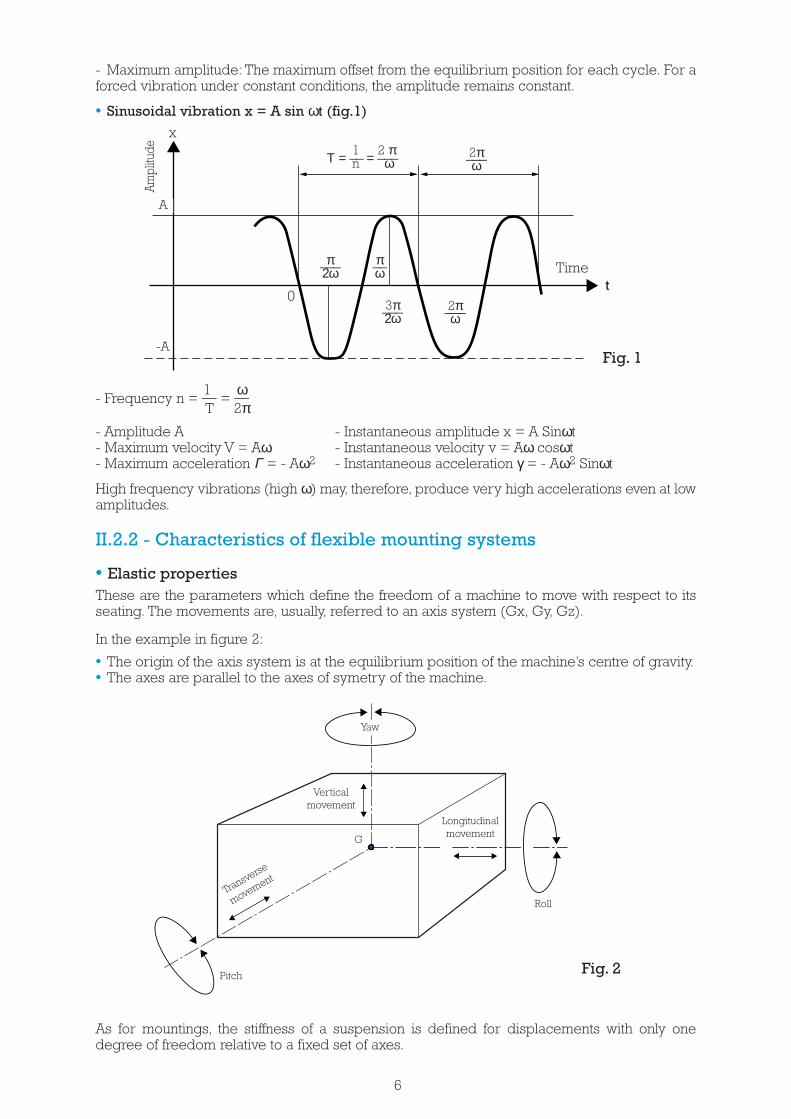
- Maximum amplitude: The maximum offset from the equilibrium position for each cycle. For aforced vibration under constant conditions, the amplitude remains constant.
• Sinusoidal vibration x = A sin ωt (fig.1)
1 ω- Frequency n = __ = __
T 2π- Amplitude A - Instantaneous amplitude x = A Sinωt- Maximum velocity V = Aω - Instantaneous velocity v = Aω cosωt- Maximum acceleration Γ = - Aω2 - Instantaneous acceleration γ = - Aω2 Sinωt
High frequency vibrations (high ω) may, therefore, produce very high accelerations even at lowamplitudes.
II.2.2 - Characteristics of flexible mounting systems
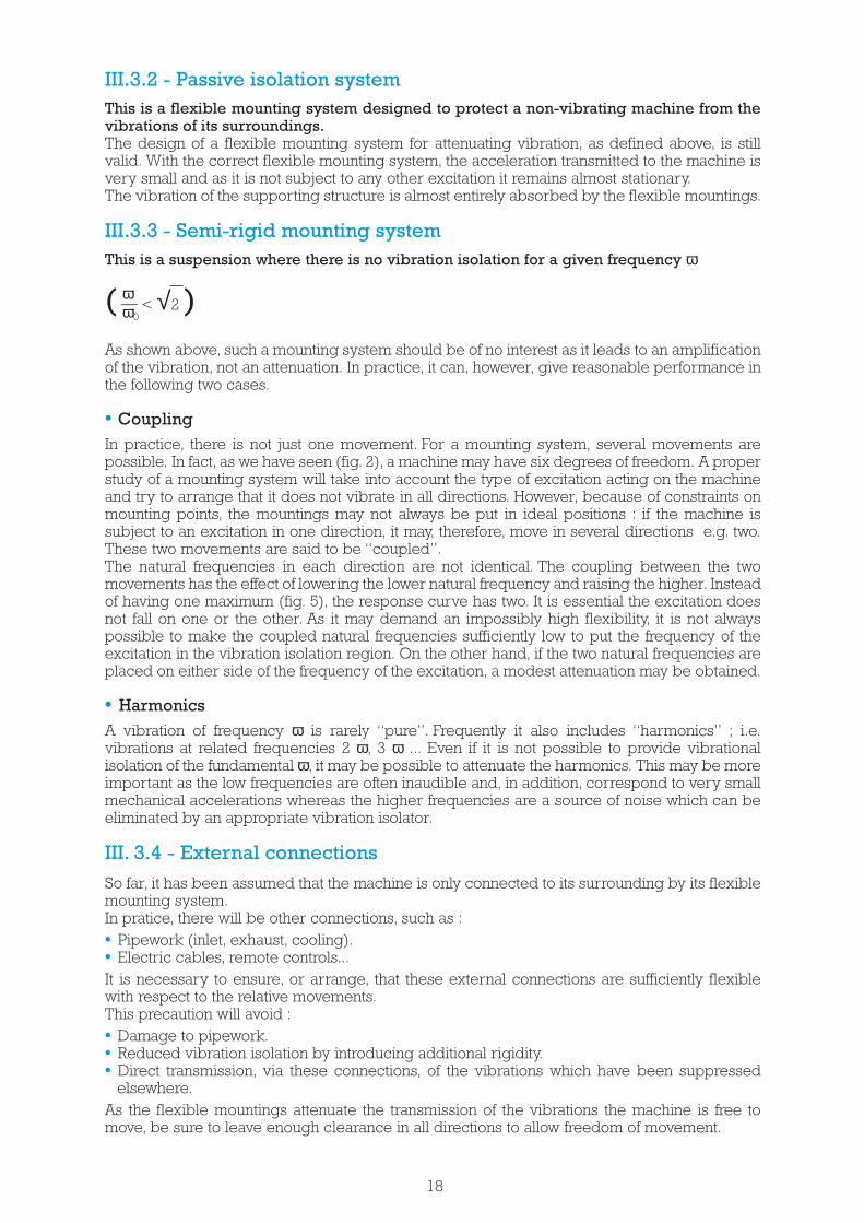
• Elastic propertiesThese are the parameters which define the freedom of a machine to move with respect to itsseating. The movements are, usually, referred to an axis system (Gx, Gy, Gz).
In the example in figure 2:
• The origin of the axis system is at the equilibrium position of the machine’s centre of gravity.• The axes are parallel to the axes of symetry of the machine.
As for mountings, the stiffness of a suspension is defined for displacements with only onedegree of freedom relative to a fixed set of axes.
6
Fig. 1
Am
plitu
de
Timet
1 2 πΤ = __ = ___n ω
π__ω
A
-A
0
x
π___2ω
3π___2ω
2π___ω
2π___ω
Fig. 2
Yaw
Verticalmovement
Transverse
movement
Pitch
Longitudinalmovement
Roll
G

- Linear stiffness :
Kx along Gx = longitudinal movementKy along Gy = transverse movementKz along Gz = vertical movementFor each axis, the linear stiffness is the sum of the linear stiffness of all the mountings.
Kx = Σ kx Ky = Σ ky Kz = Σ kz
- Torsional stiffness :
Cx about Gx = rollCy about Gy = pitchCz about Gz = yaw
The torsional stiffness of the suspension depends on :• The individual stiffness of the mountings,• The position and orientation of the mountings with respect to the centre of gravity G of the
machine.
• Damping properties
Elastomers exhibit viscous damping, the braking force applied to an elastic suspension is R x V,where :R is the resistance,V is the relative velocity of the suspended machine at time t.
If, starting with an undamped suspension, the damping is progressively increased (with allother factors remaining constant) the amplitude of the free oscillations, starting from a giveninitial offset, die away more and more quickly.The value of damping for which the return to the equilibrium position is asymptotic(without oscillation) is called the “critical damping” and is denoted by a resistance Rc.The damping factor ε is defined for a resistance R :
Rε = ___ (ε = 1 for critical damping)Rc
When suspension is subjected to forced vibrations at a frequency ω, it has been shown that, fornatural elastomers, the product ε ω remains reasonably constant. This is equally true at theresonant frequency (see below).
ε ω = εo ωo constant (ωo : is the resonant frequency).εo being the damping factor at the resonance frequency.
It can be shown that εo is an intrinsic property of the elastomer used.
εo = intrinsic damping factor.εo of a suspension = εo of each mounting (if all mountings use the same elastomer).
• Electrical characteristics
Elastomers have an electrical resistance which varies according to their composition, hardness.As a guide, the following values have been measured for our standard elastomers.
Natural Rubber hardness 45 1013 Ohm x cm2/cmhardness 60 106 Ohm x cm2/cmhardness 75 104 Ohm x cm2/cm
We have also developed special elastomers which can have a dielectric strength greater than2,000 Volts for 1 minute.
7

• Creep characteristics
The following formula, which is derived from measurements on samples, gives an estimate ofthe creep for a load which compresses a Radiaflex mount by 10% of its height at a temperatureof 30°C.The creep for an actual mounting also depends equally on its shape.
Static deflection at time t = initial static deflection x (1 + Cm x f(t))where f(t) is the value of the creep from the graph below :
Creep f(t) in compression relative to the initial static deflection.
and Cm is a correction coefficient taken from the table below according to the sample material :
Note :These values are given as a guide only. Consult us for use under other conditions (temperature,complex profiles or other elastomers).
Mounting :For applications where alignment is important, to overcome the problems of initial creep of theelastomer mountings, adjustment to align the axes of shafts should be made at least two daysafter the machine has been mounted.
Material
Standard naturalrubber
Polychloroprene 1.1 1.6 1.6
1.0 1.6 1.7
Hardness 45 Hardness 60 Hardness 75
8
t (time in days)
0.2
0.15
f(t) 0.1
0.05
050 100 150 200 250 300 350 400

- FUNCTION OF A FLEXIBLEMOUNTING SYSTEM
This is the primary function of elastic suspensions where there is vibration or shock. Thecalculations presented here assume that the linear stiffness of the mountings remainsconstant. This is true for elastomeric mountings in normal conditions of use (mechanicalvibration, normal temperature).
III.2.1 - Vibrations with only one degree of freedom
The action of a flexible mounting system is very complex. To present the principles, we willstudy a simple idealised case (fig. 3).
Taking the case of a machine of mass M constrained so that it can only move in a directionparallel to the vertical axis Gz.
It is attached to its seatings by a flexible mounting S with a stiffness K along the axis Gz.
An elastic suspension allows the static load to be more evenly distributed.If a machine rests on more than three points using “rigid” mountings, it is impossible to predictthe load on each mounting and the machine could be unevenly stressed.
With elastic mountings having known stiffness, it is possible to determine (by calculation, ordirect measurement) the deflection in each mounting and thus deduce the loading and correctany imbalance.
An elastic suspension accomodates minor differences in the distance between mountings.However many mountings there are, in order to avoid excessive local stresses, a rigid assemblyrequires very close tolerances on the distance between mountings and of the mating surfacesof the machine and its seatings.
To avoid prohibitively close manufacturing tolerances, “play” is allowed in the mountings whichgives rise to the well known problems of wear and noise due to loose fixings.
Flexible mountings allow larger manufacturing tolerances without large variation in forces.
An elastic suspension can also absorb small movements due to, for example, the expansion orthe deformation of chassis, bodyshells, girders, etc.
III
III.1 - STATIC FUNCTION
III.2 - DYNAMIC FUNCTION
Fig. 3
9
F l e x i b l emounting S
Machine
G
M
Z

• Free oscillation (natural frequency)a) Undamped (entirely theorical)The machine, having been displaced from its position of equilibrium by a distance A, oscillatessinusoidally.The equation of motion is: z = A sin ωo t
K ωoThe natural pulsation is ωo = √ ___ Proper frequency Fp = ____M 2π
The oscillation continues indefinitely with an amplitude A (as shown in Fig. 1 with ω replaced byωo).
b) Damped In this case, the machine oscillates about its position of equilibrium with a damped sinusoidalmotion (see Fig. 4).The equation of motion is:
-ε’oω’otz = A.e .sin ω’ot
The natural pulsation is:
Kω’o = √___ (1 - ε’2 ) = ωo √1 - ε’2
M o o
ε’o is the damping factor at the frequency ω’o.
As ε’o is very close to εo, the natural frequency may, therefore, be written as:
ω’o � ωo √1 - ε2o
For natural rubber, εo is small by comparison with 1 (from 0.02 to 0.1).ω’ο is, therefore, very close to ωo.
2π___ωo
2π___ωo
5π___2ωo
π___2ωo
3π___2ωo
7π___2ωo
z
A
0 t
Fig. 4
10

The variations of the transmission, coefficient λ, as a function of ω for various values of ε0 areshown in fig. 5 (page 13). ω0
Attenuation 2For rubber mountings, the term 4 ε 0 is much smaller than 1. The attenuation in % is 1 - λ :
ω 2(ω0 )- 2 1E% = 100 _______ or 100(1- _______ )
ω 2 2(ω0 ) - 1 ω(ω0 ) - 1
For a given induced frequency ω the attenuation depends on the natural frequency of thesuspension.For a particular direction, the relationship between the natural frequency, the suspension’s sub-tangent and the induced frequency are plotted on the chart fig. 6.For a particular induced frequency (for example 1500 rpm) it is possible to find the sub-tangentwhich will provide an acceptable attenuation. In general, an attenuation greater than 50% isrequired. For this example, the chart indicates that an attenuation of 80% will be achieved for anatural frequency of 10 Hz (see section IV.3.1).
2F'M 1 + 4 ε0λ = ____ = √_____________ FM (1 - ω
2 )2 + 4 ε
2
0ω02
• Forced VibrationIf the machine is now subject to forced vertical vibration induced by a sinusoidal force offrequency ω.The inducing force is F = FM sin ωt.
- For a rigid suspension : the inducing force is transmitted directly to the structure the machineis mounted on.
ωο- For an elastic suspension with a natural frequency ωο or proper frequency Fp = ____ anddamping factor εo : 2π
When the inducing force is applied, an oscillation is induced at the natural frequency ωο whichdies away rapidly so that, after a short period, only the steady state forced vibration at frequencyω remains which transmits a sinusoidal force to the surrounding structure.The force transmitted is : F’ = F’M sin ωt.A transmission coefficient λ is defined as the ratio between the amplitude of the forcetransmitted F’M to the amplitude of the inducing force FM (or, if preferred, the force that wouldbe transmitted if the suspension was not elastic).For a mounting system using elastomeric mounts, this coefficient is :
To summarise :
11
Rigid system
Flexible system(ω0, ε0)
Inducing force Transmitted force Transmission coefficient
F = FM sin ω t F = FM sin ω t λ = 1
F = FM sin ω t F’ = F’M sin ω t
2F'M 1 + 4 ε0λ = ____ = √_____________ FM (1 - ω
2 )2 + 4 ε
2
0ω02

Fig. 5
An efficient mounting system use :
ωa high value of ___ low value of ω0 low value of λω0
a moderate ε0 - limited amplification in the resonant region.- minor effect in the attenuation region.
12
Transmissioncoefficient
Amplification Attenuation
ω___ = 1 λ > Resonance ωoamplitude at resonance which increases as εοdecreases.
ω___ = √2 λ < 1ωo
Attenuation (or vibration isolation) region.ωAs ___ = increases, λ decreases.ωo
εo has very little effect.
ω___ < √2, λ > 1ωo
Amplification region for any εo.
εο = 04
3
2
1
1
√2
5
εο = 0,1
εο = 0,2
ω___ωο

Attenuation as a function of natural frequency and frequency of excitation.(A theorical graph for a mounting system without damping)
13
Fig. 6
Frequency of excitation (rpm)
Susp
en
sio
n n
atur
al fr
eq
uen
cy (
Hz)
Sub
-tan
ge
nt
(mm
)
Frequency of excitation (Hz)
0.6
0.8
1
1.4
2
3
4
5
6
8
10
14
20
30
40
50
60
690
507
388
307
248
173
127
97.1
62.1
39.8
27.6
20.3
15.5
12.3
9.9
8.2
6.9
5.1
3.9
3.1
2.5
1.7
1.3
0.97
0.62
0.40
0.28
0.20
0.16
0.12
0.10
0.08
0.07
120
150
180
210
240
270
300
330
360
420
480
540
600
720
840
960
1,08
01,
200
1,50
0
1,80
0
2,10
0
2,40
02,
700
3,00
0
3,60
0
4,20
0
4,80
0
5,40
06,
000
7,20
0
8,40
0
9,60
0
10,8
0012
,000
REGION TO BE AVOIDED
VIBRATION ISOLATION
SEMI-RIGID SUSPENSIONS
Attenuatio
n (dB)
Attenuatio
n %
2 3 4 5 6 8 10 14 20 25 35 45 60 80 100 120 140160 200
99
98
97
95
90
8070
50
40
34
30
26
20
1410
6

• Practical considerationsa - Variable speed machinesIn practice, there may not be a single, well defined value for ω, as machines may have a variablespeed (variable ω).In these cases, the vibration isolation should be determined for the lowest speed.
b - Passing through resonanceAll machines must start and stop.Starting from rest to reach the speed ω (in the vibration isolation region), it is necessary to passthrough the resonant region.It is neccesary to ensure:- that the passage through resonance is as quick as possible;- that the suspension is sufficiently well damped so that the maximum force transmittedpresents no risk for the machine, the suspension or the seating.
c - Elastomeric suspensionsFor the elastomers currently used in flexible mounting systems, the intrinsic damping factor ε0lies between 0.02 and 0.1 (it can be as high as 0.2 with synthetics such as butyl rubber).- In the vibration isolation region, the formula for the transmission coefficient is simplified as, forthe values of ε0 for natural rubber, the term 4εο
2 is negligible by comparison with 1.
1λ = _____ for ε0 between 0.02 and 0.1
ω2-1
ω²0
1- At resonance λr = _____
12 ε0
λ = ___2 ε
For natural rubber, therefore, the amplification at resonance is between:
1 1______ = 5 and _______ = 25 2 x 0.1 2 x 0.02
a) Noise and vibrationNoise is a random vibration. It is formed by the combination of a number of uncorrelatedfundamental frequencies. Noise gives rise to sound.Airbone noise is usually treated separately from structure borne noise.Sound is associated with the disturbance of a medium (solid, liquid or gaseous). Thisdisturbance is in the form of a vibration of the molecules of the medium about their position ofequilibrium.
b) Improving acousticsAn elastic suspension affects only structure borne noise.This is a vibration of the building structure and a flexible mounting system breaks thetransmission close to the source. The resilience of the attachment reduces the forcestransmitted to the base and its vibrational energy.
14
structure borne noiseairbone noise
elastic suspension
false ceiling
Soundproofed control room
airbone noise
(using Traxiflex mountings)
Source of noise Adjacent room
structure bornenoise
Transmission from one roomto another
Example:Workshop with guillotine(shock and noise)
structureborne noise

As the radiation efficiency is unchanged, the improvement in terms of radiated power (acoustic)is the same as the improvement in terms of the force transmitted. The curve giving thevibrational attenuation in % may be translated into decibels.
100Attenuation in dB is 20 log _______ where E is the attenuation in % 100 - E (structure borne, not airbone noise).
The suspension of the machinery allows the adjacent room to be sound insulated and to bemade more quiet.The rigidity of the base supporting the suspended mass must always be taken into account. Asa rule, it is considered that unless the mountings are ten times more flexible than the base thechoice of suspension must be re-considered.PAULSTRA mountings may be caracterised at high frequencies.
III.2.3 - Shocks
• The nature of shocksFor a given period, the equipment is subjected to a brief, impulsory excitation. It is the mostsevere type of excitation that it may encounter during its lifetime.During the period that the excitation is applied, the speed of the equipment will vary: it issubject to acceleration and, therefore, to a force.A system that reacts slowly will not be subject to the same shock as a system that reacts quickly.It is necessary to compare the length of period that the stimulus is applied, against the naturalfrequency of the equipment.
• Types of shocksIn practice, there are two types of problems.• The equipment is subjected to shocks which are well defined by experiments, but are very
complex and not reproducible under laboratory conditions. It is, therefore, necessary todefine an equivalent shock.
• The equipment must resist shocks which are arbitrarily defined (e.g. meeting standards).A shock is defined by an excitation which varies with time: the acceleration, the speed or thedisplacement of the point where the excitation is applied. In some cases, it is better to definethe shock as the energy transferred to the equipment (e.g. vehicle impact).
• Protection against shocksThere are two principal cases to be considered:a) Limitation of the force transmitted to the equipment:This case often appears in the following form:The equipment, moving at a known speed, meets an obstacle. The force that it can withstandwithout damage is limited to a known value.A system of rubber parts, which could be the flexible mounting system of the equipment, isplaced between the equipment and the obstacle.These parts provide a constant stiffness Kz in the direction of the shock. If there is energy W tobe absorbed in the absence of damping:
1 2 WW = __ Kz s2 The maximum force FM = Kz s = ___ The maximum force is inversely
2 s proportional to the travel.
2WThe travel Z = √___ The travel is inversely proportional to the square root of the stiffness.
Kz
Note: Some systems do not have a constant stiffness, but a stiffness which increases rapidly (e.g.compression systems). It is clear that if the energy W is not absorbed before the stiffnessincreases, the maximum force will be much higher than predicted by this formula.
15
Example of measurements made on a special Radiaflexmounting.Elastomer: polychloroprene hardness 47Amplitude ± 0.01 mm about the position under static load
DY
NA
MIC
ST
IFFN
ESS
EXCITATION FREQUENCY
N/mm4,000
3,500
3,000
2,500
2,000
1,500
1,000
500
0 50 100 150 200 250 300 350 400 450 500
Hz
b) Limiting the acceleration of particular parts of the equipmentIn this case the shock must be described in terms of its potential to destroy. The efficiency ofthe protection system is measured by its ability to reduce this potential.A shock to the equipment can damage a component part if this part is induced to vibrate at anamplitude which is incompatible with its mechanical characteristics thus causing it to break.
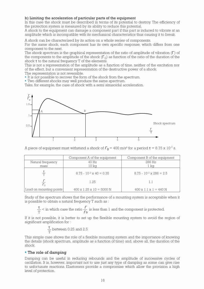
A shock can be characterised by its action on a whole series of components.For the same shock, each component has its own specific response, which differs from onecomponent to the next.The shock spectrum is the graphical representation of the ratio of amplitude of vibration (Γ) ofthe components to the amplitude of the shock (Γ0) as function of the ratio of the duration of theshock τ to the natural frequency T of the elements.This is not a representation of the amplitude as a function of time, neither of the excitation norof the effect, but a convenient representation of the destructive power of a shock.The representation is not reversible.• It is not possible to recover the form of the shock from the spectrum.• Two different shocks may well produce the same spectrum.Take, for example, the case of shock with a semi sinusoidal acceleration.
Study of the spectrum shows that the performance of a mounting system is acceptable when itis possible to obtain a natural frequency T such as :
τ Γ__ < in which case the ratio __ is less than 1 and the component is protected.T Γο
If it is not possible, it is better to set up the flexible mounting system to avoid the region ofsignificant amplification for :
τ__ between 0.25 and 2.5T
This simple case shows the role of a flexible mounting system and the importance of knowingthe details (shock spectrum, amplitude as a function of time) and, above all, the duration of theshock.
• The role of dampingDamping can be useful in reducing rebounds and the amplitude of successive cycles ofoscillation. It is, however, important not to use just any type of damping as some can give riseto unfortunate reactions. Elastomers provide a compromise which allow the provision a highlevel of protection.
16
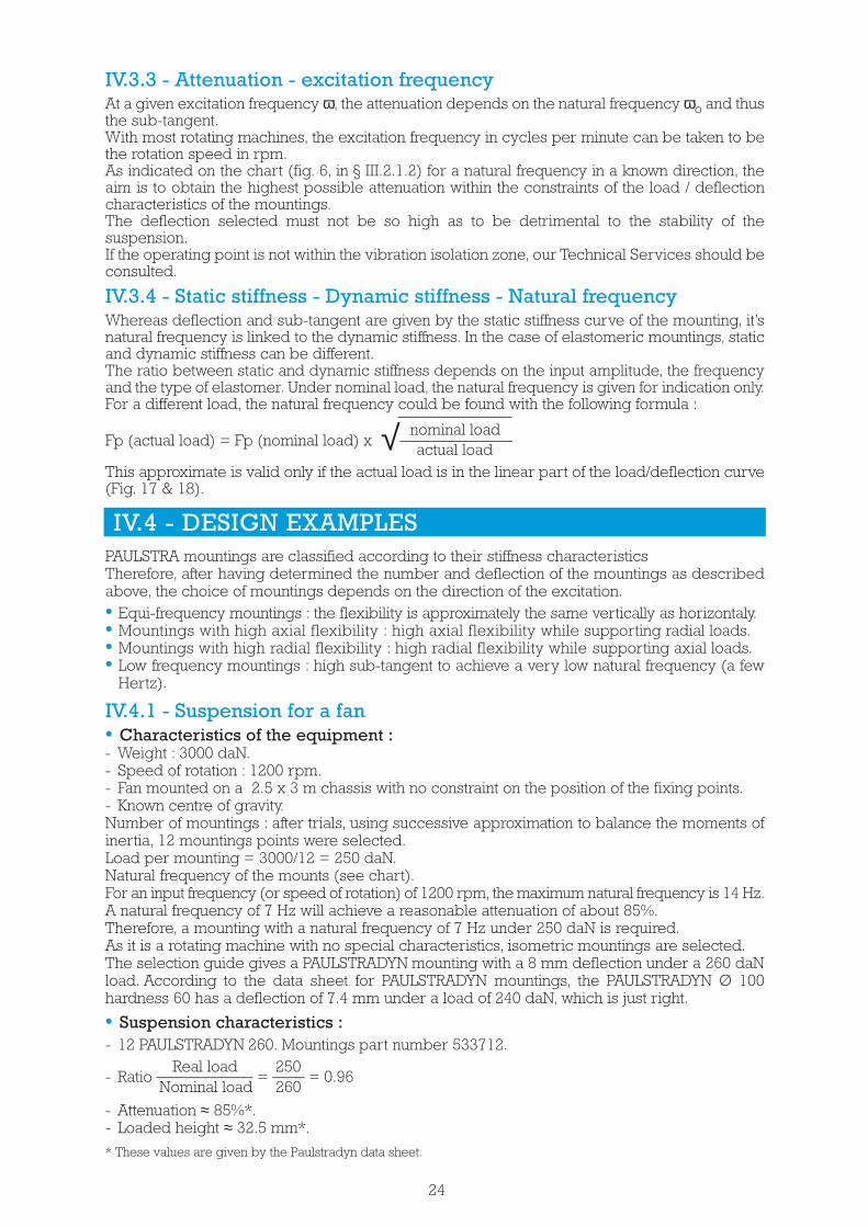
A piece of equipment must withstand a shock of Γ0 = 400 m/s² for a period τ = 8.75 x 10⁻³ s.
Natural frequencymass
τ__T
Γ__Γ0
Load on mounting points
Component A of the equipment40 Hz10 kg
8.75 - 10-3 x 40 = 0.35
1.25
400 x 1.25 x 10 = 5000 N
8.75 - 10-3 x 286 = 2.5
1.1
400 x 1.1 x 1 = 440 N
Component B of the equipment286 Hz
1 kg
Shock spectrum
1 2 3 4 5
A B
Γ__Τ
Γ__Γο
1.5
1
0.5

III.3.1 - Active isolation systemThis is a flexible mounting system designed to prevent a machine from transmitting itsvibrations to its seating or foundation.This is the theorical problem (with one degree of freedoom which was treated, by attenuatingthe vibration, in the preceding pages.The vibration isolation does not stop the machine from vibrating, but it reduces the transmissionof these vibrations.By comparison with a rigid suspension (which transmits the vibrations) the amplitude of themachine’s vibrations may be greater. The machine is, to an extent, freed from its fixed seating.This is the case for the automobile “floating engine” which, mounted on a flexible mountingsystem, no longer transmits its vibrations to the bodywork and the passengers due to increasedmobility under the bonnet (hood).If excessive movement cannot be tolerated, the only way to reduce it, without reducing theefficiency of the flexible mounting system, is to increase the suspended mass (ballasting).For a given excitation, the amplitude is inversely proportional to the mass.This is necessary for certain machines which produce particulary severe vibration : slow singlecylinder compressors, centrifuges, power hammers etc.These machines, are therefore, fixed rigidly to a chassis or heavy slabs and the whole assemblyis suspended.Increasing the suspended mass allows good vibration isolation with limited vibration of thesuspended assembly.It is worthwhile suspending complete assemblies rather than individual machines : generatingsets, motor/compressor units, motor/pump units.
• Important noteTwo points must always be borne in mind when designing equipment :• Firstly, that a high level of protection requires great flexibility which requires considerable
clearance between the equipment and its surrounding.• Secondly, that the equipment will oscillate and room must be allowed for the rebound in case
of shock. Travel limiters must be positioned so that they do not impede the operation of theflexible mounting system during the shocks allowed for in the design.
A flexible mounting system using rubber protects against shock by reducing the travel andmaximum force. It is necessary to allow enough clearance for the rebound.
III.2.4 - General caseTheoretical study above is based on a very simple case :movement with only one degree of freedom (vertical) with only one excitation (also vertical)aligned with both the centre of gravity of the suspended machine and the centre of elasticity ofthe mounting system.In general, things are not so simple. The machine can move in any of the degrees of freedom(rotation or linear movement). In theory, there are as many natural frequencies as there aredegrees of freedom.These natural frequencies are not independent but are “coupled”. If one of these is excited inone degree of freedom, it can, as a result of the coupling, give rise to vibrations at the samefrequency in other degrees of freedom.To analyse the whole behaviour, the stiffness in all directions needs to be taken into accountand not just the mass of the suspended body but also the moments of inertia so that rotationalbehaviour can be evaluated.In addition there may be not one but several forced vibrations, with variable frequenciesapplied to several different points, in various directions or about various axes.Even general cases can be very complex however symmetrical structures and mountingarrangements allow the use of the single degree of freedom analysis shown above. In othercases only an in-depth study allows an effective solution to be found. Our Technical Services arethere to help you to define it.
III.3 - VARIOUS TYPES OF FLEXIBLE MOUNTINGSYSTEMS
17
III.3.2 - Passive isolation systemThis is a flexible mounting system designed to protect a non-vibrating machine from thevibrations of its surroundings.The design of a flexible mounting system for attenuating vibration, as defined above, is stillvalid. With the correct flexible mounting system, the acceleration transmitted to the machine isvery small and as it is not subject to any other excitation it remains almost stationary.The vibration of the supporting structure is almost entirely absorbed by the flexible mountings.
III.3.3 - Semi-rigid mounting systemThis is a suspension where there is no vibration isolation for a given frequency ω
ω( __ < √2 )ω0
As shown above, such a mounting system should be of no interest as it leads to an amplificationof the vibration, not an attenuation. In practice, it can, however, give reasonable performance inthe following two cases.
• CouplingIn practice, there is not just one movement. For a mounting system, several movements arepossible. In fact, as we have seen (fig. 2), a machine may have six degrees of freedom. A properstudy of a mounting system will take into account the type of excitation acting on the machineand try to arrange that it does not vibrate in all directions. However, because of constraints onmounting points, the mountings may not always be put in ideal positions : if the machine issubject to an excitation in one direction, it may, therefore, move in several directions e.g. two.These two movements are said to be “coupled”.The natural frequencies in each direction are not identical. The coupling between the twomovements has the effect of lowering the lower natural frequency and raising the higher. Insteadof having one maximum (fig. 5), the response curve has two. It is essential the excitation doesnot fall on one or the other. As it may demand an impossibly high flexibility, it is not alwayspossible to make the coupled natural frequencies sufficiently low to put the frequency of theexcitation in the vibration isolation region. On the other hand, if the two natural frequencies areplaced on either side of the frequency of the excitation, a modest attenuation may be obtained.
• HarmonicsA vibration of frequency ω is rarely “pure”. Frequently it also includes “harmonics” ; i.e.vibrations at related frequencies 2 ω, 3 ω ... Even if it is not possible to provide vibrationalisolation of the fundamental ω, it may be possible to attenuate the harmonics. This may be moreimportant as the low frequencies are often inaudible and, in addition, correspond to very smallmechanical accelerations whereas the higher frequencies are a source of noise which can beeliminated by an appropriate vibration isolator.
III. 3.4 - External connections
So far, it has been assumed that the machine is only connected to its surrounding by its flexiblemounting system.In pratice, there will be other connections, such as :• Pipework (inlet, exhaust, cooling).• Electric cables, remote controls...It is necessary to ensure, or arrange, that these external connections are sufficiently flexiblewith respect to the relative movements.This precaution will avoid :• Damage to pipework.• Reduced vibration isolation by introducing additional rigidity.• Direct transmission, via these connections, of the vibrations which have been suppressed
elsewhere.As the flexible mountings attenuate the transmission of the vibrations the machine is free tomove, be sure to leave enough clearance in all directions to allow freedom of movement.
18

Information about... ...to determine the fundamental parametersof the flexible mounting system
...the MACHINE and...Centre of gravity Weight Load on each mountingNumber and position of mountingpoints (supplied or possible)
the DISTURBANCE...Frequency of disturbance Deflection of the mountings for the(or speed of rotation) required attenuation
Principle direction of Stiffness characteristics for thethe disturbing force mounting
When designing a flexible mounting system, it is essential to know, precisely the basiccharacteristics of the machine to be suspended.
It is extremely useful to have a drawing (even if it is schematic) which shows the position of thecentre of gravity and the mounting points provided.The drawing may also allow the evaluation of certain parameters which may be necessary andwhich are often unknown to either the manufacturers or the users (e.g. moments of inertia).
For passive isolation, it is necessary to obtain the maximum of information about the externalvibrations which may disturb the machine.In any case, for complex problems (oscillations in many degrees of freedom, multipleexcitation), it is advisable to consult our Technical Services.
For simple problems (one degree of freedom, or two degrees of freedom with the centre ofgravity close to the mounting plane) it is possible to design the suspension, as shown below,with a minimum of information about the machine and the disturbance.
- DESIGNING A FLEXIBLEMOUNTING SYSTEM
IV.1.1 - Ask the manufacturerIn most cases, the manufacturer of the machine should be able to supply the exact position ofthe centre of gravity as well as the weight.Consult the manufacturer.
IV.1.2 - Graphical method for finding the centre of gravity of an assemblyThis is suitable for assemblies of units for which the individual weights and centres of gravityare known.
Important notes :• Using a graphical method, it is important to represent dimensions using a well determined scale
and the weights by vertical lines whose lengths are proportional to their size (e.g. 1 cm for10 daN).
• If the centres of gravity considered in this section are not in the same vertical plane, theprocedures proposed here should be applied twice : for the front and for the side view withthe outlines corresponding to each view.
IV
IV.1 - DETERMINING THE CENTRE OF GRAVITY
19

Fig. 9Draw : AP’B = BPB Join P’A and P’B
BP’A = APAThe centre of gravity G lies at the intersec-tion of the lines P’A P’B and AB.Measure a and b.
• An assembly of two units
• An assembly of three or more units
Proceed, stage by stage, as described above using groups of two units or sub-assemblies withcentres of gravity and weight known or calculated.
IV.1.3 - Experimental determination of the centre of gravity of a unit
This method is used where the above two methods prove to be impossible or difficult (complexgeometry).
• Using a roller
For a given orientation (length, width and height) the centre of gravity is in the vertical planepassing through the axis of the roller when the machine is balanced. The centre of gravity is atthe intersection of the three planes thus determined.
• By “hanging”
Suspended from a cable, the centre of gravity is on the vertical dropped from the suspen-sionpoint. To find the exact centre of gravity, repeat the operation twice, using a different suspensionpoint each time.
20
Fig. 8
Two units of weights PA and PB respectivelywith centres of gravity A and B separated by L.
a b
L
PA
P’B
P’A
PB
A•A•• B• B
G
•
L L’
PB
PA
PC
P’A
PC
P’C
P’B
C•
A• A•• B
B• B
•
A• C
•C•
G
••G’
•G’

IV.1.4 - Analytical determination of the centre of gravity ofan assembly of several masses
An assembly of several masses m1, m2, ... mn is fixed in space.It is assumed that the coordinates, within an arbitrary Cartesian set, of each mass are known.
X1 X2 Xnm1 { Y1 m2 { Y2 mn{ Yn
Z1 Z2 Zn
The mass of the assembly M = m1 + m2 + ... + mn acts at the coordinates of the centre of gravityof the whole : x, y, z
m1 x1 + m2 x2 +...+ mn xnx = _________________________M
m1 y1 + m2 y2 +...+ mn yny = _________________________M
m1 z1 + m2 z2 +...+ mn znz = _________________________M
Important note : The coordinates of the centres of gravity may be negative and must be usedwith their sign.
IV.2.2 - Number and position of the mounting points are predeterminedIn this case, it may not be possible to have the same load on each mounting.
• Four mounting pointsA, B, C and D are the mounting points,G the centre of gravityP the total weight suspendedPA, PB, PC and PD are the loads on the mounting points A, B, C and D.
m2 l2 m1 l2PA = ___ . ___ . P PB = ___ . ___ . Pb a b a
m1 l1 m2 l1PC = ___ . ___ . P PD = ___ . ___ . Pb a b a
If PA, PB, PC and PD are significantly different, it is, theoretically, necessary to choose fourdifferent mountings which will give the same deflection under the various loads.
IV.2.1 - Number and position of the mounting points are not predeterminedIn this case, the number and position of the mountings are determined in such a way that theload on each mounting is the same for all mounting points.Taking, for example, a symmetrical machine with :
G : the centre of gravityP : the weight of the machineCalculate the position of 6 mounting points such that the loadon all the mounting points is P1
P1 l’1 + P1 l’2 = P1 l1Weight
from which l1 = l’1 + l’2 and the load per point = ______6
IV.2 - DETERMINING THE LOAD PER MOUNTING
21
Fig. 14
Fig. 13
+ A D +
+ B C +
G
I1 I2
m2
m1b
a
m1
y1
x1
z1
y
x
z
o
•
•
•
•
o o o
o o oG
l1 l’1
l’2

• More than four mounting points (fig. 15)In this case it is best if the assembly is symmetrical about avertical plane. This is assumed to be true in the following.To the left of G, there are 2n identical mountings.To the right of G, there are 2p identical mountings which are,possibly, different from the 2n mountings to the left.The problem is to set the difference between the left handand right hand mountings so that the deflection under load ofthe 2n + 2p mountings are all the same.Under these conditions, all the mountings to the left of G willbe supporting the same load Q and all those to the right willbe supporting the same load R.This will give :
Q (l1 + l2 + ... + ln) = (λ1 + λ2 + ... + λp)2 nQ + 2 pR = P
From which the mountings charge is :
λ1 + λ2 + λpQ = ________________________________________ . P
2 n (λ1 + λ2 + ... + λp) + 2 p (l1 + l2 + ... + ln)
l1 + l2 + lnR = ________________________________________ . P2 n (λ1 + λ2 + ... + λp) + 2 p (l1 + l2 + ... + ln)
If Q and R are not too different, the same size mountings maybe used but with different hardness elastomers.
Example (fig.16)Taking a symmetrical machine with an offset centre of gravityG and 6 mounting pointsn = 2 et p =1.which gives :
λQ = ______________ . P
4 λ + 2 (l1 + l2)
l1 + l2R = ______________ . P4 λ + 2 (l1 + l2)
IV.2.3 - Important notes
If a single size of mounting is used, but different hardness elastomers are choosen, there is ahigh risk that the mountings may be interchanged which may degrade the attenuation of thesuspension. The machine must be mounted with great care.There are, however, benefits from using identical mountings to build a suspension. If thepredetermined mounting points of the chassis do not allow a centered suspension, the solutionis to attach these to a false chassis, as rigid as possible, to which the desired number of identicalflexible mountings are attached in the positions required. If this false chassis is a slab ofconcrete (or inertia block) the suspended mass is increased which improves the quality of thesuspension.
IV.3.1 - Deflection and sub-tangentFig. 17 is a graphical representation of the derivation of the deflection and sub-tangent from theload/deflection curve.
IV.3 - DETERMINING THE DEFLECTION
22
If the machine weighs 500 daN and λ = 0.4 m ; l1 = 0.3 m ; l2 = 0.9 m, then Q = 50 daN and R =150 daN.
Fig. 16
Fig. 15
+
+
+ +
+ +
+
+ + +
+++
Q Q Q
G
G
R R
+ + + +
l1
l2
ln
λ1
λP
==
+Q +Q R+
+Q +Q R+G
l2
l1λ
= =

For most PAULSTRA mountings, the load/deflection curve is linear in the region of static loads(fig. 18) and, as a result, the sub-tangent and the deflection are identical.
The curve in fig. 17 is typical of EVIDGOM mountings.For these it is best to work at the point of inflection of the curve where the sub-tangent is thelargest possible and so the natural frequency is as low as possible.The deflection does not indicate the amplitude of the oscillations of the machine.
IV.3.2 - Operating regions
The region OM is the static load region. The deflection is approximately proportional to theload.
In the data sheets, the coordinates of the point M are given as the NOMINAL STATIC LOAD.
The region MP is the dynamic load region corresponding to normal, repeated shocks providedthat the rate and total deflection stay within normal limits.
In the region PZ, which corresponds to exceptional, accidental shocks, the curve rises rapidly.The stiffness increases progressively which has the effect of reducing the amplitude of themovement. Note that, because of the natural damping properties of the rubber, this increasealso depends on the speed of impact.
For a given static load, the deflection corresponds to the compression of the mounting underthat load, but the stiffness about the position under load is given by the sub-tangent (theprojection of the tangent onto the axis). This is the elasticity which determines the naturalfrequency of the mounting.
Fig. 17
Fig. 18
23
K 1ωo = C√ __ = √ __________ (C = constant)
M sub-tangent
staticload
load
load
actual deflection
sub-tangent
deflection
deflection
M
P
Z500
400
300
200
100
0 5 10 15 20
m
IV.3.3 - Attenuation - excitation frequencyAt a given excitation frequency ω, the attenuation depends on the natural frequency ωo and thusthe sub-tangent.With most rotating machines, the excitation frequency in cycles per minute can be taken to bethe rotation speed in rpm.As indicated on the chart (fig. 6, in § III.2.1.2) for a natural frequency in a known direction, theaim is to obtain the highest possible attenuation within the constraints of the load / deflectioncharacteristics of the mountings.The deflection selected must not be so high as to be detrimental to the stability of thesuspension.If the operating point is not within the vibration isolation zone, our Technical Services should beconsulted.
IV.3.4 - Static stiffness - Dynamic stiffness - Natural frequencyWhereas deflection and sub-tangent are given by the static stiffness curve of the mounting, it’snatural frequency is linked to the dynamic stiffness. In the case of elastomeric mountings, staticand dynamic stiffness can be different.The ratio between static and dynamic stiffness depends on the input amplitude, the frequencyand the type of elastomer. Under nominal load, the natural frequency is given for indication only.For a different load, the natural frequency could be found with the following formula :
nominal loadFp (actual load) = Fp (nominal load) x √______________
actual loadThis approximate is valid only if the actual load is in the linear part of the load/deflection curve(Fig. 17 & 18).
PAULSTRA mountings are classified according to their stiffness characteristicsTherefore, after having determined the number and deflection of the mountings as describedabove, the choice of mountings depends on the direction of the excitation.• Equi-frequency mountings : the flexibility is approximately the same vertically as horizontaly.• Mountings with high axial flexibility : high axial flexibility while supporting radial loads.• Mountings with high radial flexibility : high radial flexibility while supporting axial loads.• Low frequency mountings : high sub-tangent to achieve a very low natural frequency (a few
Hertz).
IV.4.1 - Suspension for a fan• Characteristics of the equipment :- Weight : 3000 daN.- Speed of rotation : 1200 rpm.- Fan mounted on a 2.5 x 3 m chassis with no constraint on the position of the fixing points.- Known centre of gravity.Number of mountings : after trials, using successive approximation to balance the moments ofinertia, 12 mountings points were selected.Load per mounting = 3000/12 = 250 daN.Natural frequency of the mounts (see chart).For an input frequency (or speed of rotation) of 1200 rpm, the maximum natural frequency is 14 Hz.A natural frequency of 7 Hz will achieve a reasonable attenuation of about 85%.Therefore, a mounting with a natural frequency of 7 Hz under 250 daN is required.As it is a rotating machine with no special characteristics, isometric mountings are selected.The selection guide gives a PAULSTRADYN mounting with a 8 mm deflection under a 260 daNload. According to the data sheet for PAULSTRADYN mountings, the PAULSTRADYN Ø 100hardness 60 has a deflection of 7.4 mm under a load of 240 daN, which is just right.
• Suspension characteristics :- 12 PAULSTRADYN 260. Mountings part number 533712.
Real load 250- Ratio ____________ = ____ = 0.96
Nominal load 260
- Attenuation ≈ 85%*.- Loaded height ≈ 32.5 mm*.
* These values are given by the Paulstradyn data sheet.
IV.4 - DESIGN EXAMPLES
24

IV.4.2 - Suspension of an engine/hydraulic pump unit mounted on an excavator
• Characteristics of the assembly :
- Weight : 1200 daN.- Speed of rotation : 1500 rpm.- Known centre of gravity.- 6 mountings points.
Load per mounting : 1200/6 = 200 daN.Deflection (see chart, fig. 5).For a frequency of 1500 rpm, a deflection of 3 mm will achieve an attenuation of approximately85 %.
The vibrations are predominantly vertical and the unit needs to be restrained laterally to copewith the movement of the excavator in operation. Mountings with dominant axial flexibility areselected.
The PAULSTRA mounting selection guide gives a STABIFLEX mounting with a deflection of5 mm for a load of 210 daN. According to the STABIFLEX mounting data sheet, the mountingrequired is a STABIFLEX 530622 hardness 45 with a square base.
• Suspension characteristics (under 1200 daN at 1500 rpm) :
- 6 STABIFLEX mountings reference 530622 hardness 45.- Deflection 4.7 mm.- Theoretical attenuation 85% (16 dB).
25
IV.4.3 - Suspension of a sieve
• Characteristics of the equipment :
- Weight : 400 daN.- Vibration frequency (horizontal) : 1200 cycles/mn or 20 Hz.- Known centre of gravity.- 6 mounting points.
Load per mounting : 400/6 = 66 daN.Deflection (see chart, fig. 5).For a frequency of 20 Hz, a deflection of 6 mm will achieve an attenuation of approximately 70%.
Mountings characteristics required :
1) mountings which will withstand the vertical load ;
2) mountings with a radial flexibility very much greater than the axial flexibility (mounting withdominant radial flexibility) ;
3) providing vibration isolation vertically (axially), which, taking account of requirement (2), willassure the horizontal vibration isolation.
The PAULSTRA mounting selection guide gives a RADIAFLEX cylindrical stud giving adeflection of 8 mm for a load of 70 daN.According to the RADIAFLEX mounting data sheet, the mounting required is a stud Ø 30 height30 mm with 2 mounting bolts (ref. 521312).The radial flexibility (shear) is considerably higher than axial flexibility (compression).
• Suspension characteristics :
- 6 RADIAFLEX cylindrical mounts with 2 screws reference 521312 (theoretical vibrationattenuation : 80% - 14 dB).
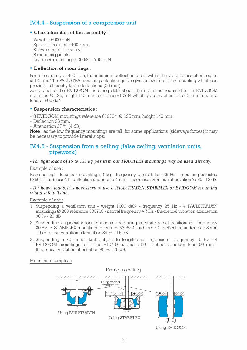
IV.4.4 - Suspension of a compressor unit
• Characteristics of the assembly :- Weight : 6000 daN.- Speed of rotation : 400 rpm.- Known centre of gravity.- 8 mounting points.- Load per mounting : 6000/8 = 750 daN.
• Deflection of mountings :For a frequency of 400 rpm, the minimum deflection to be within the vibration isolation regionis 12 mm. The PAULSTRA mounting selection guide gives a low frequency mounting which canprovide sufficiently large deflections (26 mm).According to the EVIDGOM mounting data sheet, the mounting required is an EVIDGOMmounting Ø 125, height 140 mm, reference 810784 which gives a deflection of 26 mm under aload of 800 daN.
• Suspension characteristics :- 8 EVIDGOM mountings reference 810784, Ø 125 mm, height 140 mm.- Deflection 26 mm.- Attenuation 37 % (4 dB).Note : as the low frequency mountings are tall, for some applications (sideways forces) it maybe necessary to provide lateral stops.
IV.4.5 - Suspension from a ceiling (false ceiling, ventilation units,pipework)
- For light loads of 15 to 135 kg per item our TRAXIFLEX mountings may be used directly.
Example of use :False ceiling - load per mounting 50 kg - frequency of excitation 25 Hz - mounting selected535611 hardness 45 - deflection under load 4 mm - theoretical vibration attenuation 77 % - 13 dB.
- For heavy loads, it is necessary to use a PAULSTRADYN, STABIFLEX or EVIDGOM mountingwith a safety fixing.
Example of use :1. Suspending a ventilation unit - weight 1000 daN - frequency 25 Hz - 4 PAULSTRADYN
mountings Ø 200 reference 533718 - natural frequency ≈ 7 Hz - theoretical vibration attenuation90 % - 20 dB.
2. Suspending a special 5 tonnes machine requiring accurate radial positioning - frequency20 Hz - 4 STABIFLEX mountings reference 530652 hardness 60 - deflection under load 8 mm- theoretical vibration attenuation 84 % - 16 dB.
3. Suspending a 20 tonnes tank subject to longitudinal expansion - frequency 15 Hz - 4EVIDGOM mountings reference 810733 hardness 60 - deflection under load 50 mm -theoretical vibration attenuation 95 % - 26 dB.
Mounting examples :
26
Fixing to ceiling
Using PAULSTRADYNUsing STABIFLEX
Using EVIDGOM
Suspendedequipment

PAULSTRAELASTOMER RANGE
29

LOW FREQUENCYHIGH RADIAL FLEXIBILITY
M O U N T I N G S S E L E C T I O NG U I D E
HIGH AXIAL FLEXIBILITY
RADIAFLEX PAULSTRADYN® STABIFLEX S.C.
Deflection - mm Deflection - mm* Deflection - mm Deflection - mm
Nominalstatic load
(daN)
* Range of parts using the same deflection (± 6.5 mm) to provide a natural frequency at 7 Hz.
30
* 0.743.5 * 0.883 0.510
2 - 4 *124 - 515
1.5 to 5.5 * 1.520725
4.5 - 6 * 1.2302.5 to 7350.6 to 8 3.5 0.840
453 to 10 * 2.5502.5 to 9 3 1.8 to 3.5607.5 - 8 * 4701.5 to 7 1.5 - 4803 to 8 3.590
* 3 - 3.51007 to 11 2 - 3120
4125* 3.5130
4.5 to 8.5 1.5 - 31504 to 9 * 3.5 - 4160
10 - 11 3 - 4190* 5200
52207 to 11 * 3 - 4 2 - 5250
4.52756 to 14 * 2 - 43009 to 15 3.5 - 4.53505 to 17 * 3.5 - 7 4.5 - 64007 to 19 8 3 - 6.5450
17 *5002.5 - 3.5 - 4.5550
7 to 10 * 560018 8 6.5700
*8006.5825
12 5 - 89007 - 8950
* 810008 3 - 5 - 9.51100
7.5 111250* 3 - 9.51400
1116008 8.51800
20008.521005230052600
500080009000
14000

4
HIGH SHEARFLEXIBILITY
HIGH AXIAL FLEXIBILITYLOW FREQUENCY
10
EVIDGOM® S.T.C. TRAXIFLEX SANDWICH
4
40.7
0.7 410
1.244
15 1.2
418 1.2
2
1.2
20 2
2
243
10 - 16 - 26
1 - 3
28
35
50 125060 660 5
675
122025303540455060708090
100120125130150160190200220250275300350400450500550600700800825900950
1000110012501400160018002000210023002600500080009000
14000200003000045000
Deflection - mm
31
M O U N T I N G S S E L E C T I O NG U I D E
8
Deflection - mmDeflection - mmDeflection - mm
Nominalstatic
load (daN)

S.T.C. ®S.C.STABIFLEXRADIAFLEX PAULSTRADYN®
In general :For fixed installations : RADIAFLEX. PAULSTRADYN and BECA.For mobile installations : STABIFLEX, S.C., S.T.C.Avoid using the mount with the rubber to metal bond area in tension.These mounts should only be used in compression or shear.
M O U N T I N G SA P P L I C A T I O N G U I D E
FANS
AIR CONDITIONING
PUMPS
COMPRESSORS
GEARBOXES
GENERATING SETS
IC ENGINES
PLANT CABS
VIBRATING TABLES/SCREENS
HOPPERS
MACHINE TOOLS
PRESSES, GUILLOTINES
GANTRIES
CIVIL ENGINEERING
CEILING,. PIPEWORK
LABORATORY EQUIPMENT
ELECTRICAL ENCLOSURE
TRANSFORMERS
FRAGMENTERS
SIEVES
HIGHRADIAL
FLEXIBILITY
LOWFREQUENCY
HIGH AXIAL FLEXIBILITY
32
APPLICATIONS
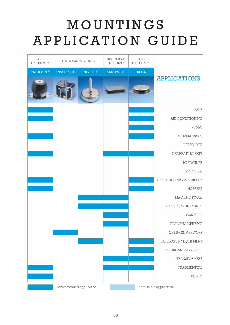
APPLICATIONS
FANS
AIR CONDITIONING
PUMPS
COMPRESSORS
GEARBOXES
GENERATING SETS
IC ENGINES
PLANT CABS
VIBRATING TABLES/SCREENS
HOPPERS
MACHINE TOOLS
PRESSES, GUILLOTINES
GANTRIES
CIVIL ENGINEERING
CEILINGS, PIPEWORK
LABORATORY EQUIPMENT
ELECTRICAL ENCLOSURE
TRANSFORMERS
FRAGMENTERS
SIEVES
LOWFREQUENCY
HIGH AXIAL FLEXIBILITYHIGH SHEARFLEXIBILITY
LOWFREQUENCY
33
M O U N T I N G SA P P L I C A T I O N G U I D E
Recommended application Admissible application
NIVOFIXTRAXIFLEXEVIDGOM® SANDWICH BECA

RADIAFLEX
• Metalwork: Mild steel, plated.• Natural rubber, bonded, cylindrically shaped.• Welded fixings: 5 styles (single sided threaded stud, single sided
threaded hole, double threaded stud, double threaded holes,combination fixing).
In Europe, we often use different screw standards than our frenchstandard.
To better satisfy this need, Paulstra has created a new range TRadiaflexEurope.
This range is available with the 4 usual welded fixings and with a newfixing: the threaded hole stop.
The design of the RADIAFLEX mount gives the following basiccharacteristics:
• Radial elasticity greater than axial elasticity.• The rubber works in:
- compression (axial).- shear (radial).- compression/shear according to the fixing method.
Advantages:
• Simple to fix.• Simple and economical.• Extensive range:
- 13 stud diameters.- Several heights for each diameter.- 5 methods of fixing.
Recommendations:• Operation in shear is very useful for vibration isolation provided that
the radial forces are not too great.
DESCRIPTION
CHARACTERISTICS
34

40
****
0.750.9
1.51.25
1.21.6
1210
66
M3M3
88
950950600500450
4535353535
M14
3030407080
557
1517
Ref.Deflectmm
Max.loaddaN
Deflectmm
Max.loaddaN
GmmØ CB
mm
1210
Ø Amm
15223040
253645
253545
2028354045
3040
521601521603521641
25400300250
58
11
303030
4.579
60 M10
25300250190
68
11
252525
4.579
521580521581521582
M1050
25450350300
81114
353535
6.51115
521705521710521711
70355070
M10
28 600 9 40 7 52165840 M12521803521840521841521842521843
779
1719
4040404040
80
100 471100
900750
81219
606060
71017
521908521909521910
405580
M16
521293521128521295
1.524
1.52.52.5
233.5
1210
810M5
101520
M4 10 20 1.53 2.5 1.5
2521650521651
1015
M6 16.5
4035303025
0.634.55.57
5554.54.5
12.53.54.54.5
521178521249521297521299521319
8.515202530
521292521294521296521298
1.5245
2.52.52.52
1.5345
20201515
12M510152025
521655521656521652521653
1.52.546
8888
1.52.527.5
80605050
2.5467.5
11111111
3589
90807060
25M8
101522253040
18M610152030
521308521310521312521314
12.5
30
513601511625511635511645
369
11
350400300250
25M1022253645
60
511525511535511545
69
11
300250190
25M10253545
50
40
511308511310511312511314
511265511270511251511275511280511285511290
511110511128511115511125
22.533.5
121110
8
10M51013.51520
12.5
16
3.5689
90807060
25M815223040
30
Ref.Compression
Bmm
1015
Deflectionmm
Max. loaddaN
Ø C
511150511151
232010M4
Gmm
Ø Amm
2345
20201515
10152025
8.515202530
M5 12511292511294511296511298511200511215511220511225511230
1.5455.57
M6 16.5
4035303025
20
25.510151922253040
511450511401511452511454511456
568
1011
160150120120120
25M10
2025354045
511157511161
710
12012020M830
40
Threaded hole fixing on request (except Ø 12.5).See current price list for availability of items.
DIMENSIONS AND COMPRESSIVE LOADS
*The shear characteristics are measured under Axial Load.**See VIBRACHOC elastomer range : references E3RP.
See Vibrachoc elastomer range :Threaded studs
35
SINGLE STUD FIXING DOUBLE STUDS FIXING
M8M8 20
80605550505050
23.54.55.568
10
1880605050
23.558
511158511155511159511160
10152030
M6
25450350300
91214
511735511750511770
70355070
M10
4535353535
1100950600500450
68
101719
513801511830511840511870511880
80
2530407080
M14
Compression Shear*
16
20
20
806050505050
1.52.545.57.5
10
888886.5
1.52.544.566
521340521341521251521342521343521344
25.5
25
160150120120120
468
1011
2020202020
35.56.57.59
521450521401521452521454521456
M10
20 150120
610
2020
5.57.5
521181521657M8
New RADIAFLEXreferences
Ø A Ø A
Ø CØ CG
B BG
Ø C
25.5
M6 4 35 4 51115420 15
M6 4605550
3,55,58
511164511162511163
25,5152030
M8 6 80 6 51115630 22
M10 8
150120120120
4.57
1011
20202020
520520520521520522520523
28354045
5.56.57.59
40
Hmm
Max.loaddaN
Deflect.mm
Max.loaddaN
Deflect.mm
Ref.Bmm
Ø Cmm
47
1100900750600
8121223
7101720
60606060
520100520101520102520103
100
405580
100
M16 14
70
801235
600500400
81719
404040
520044520045520046
407080
M147
1517
925450350300
7.51014
353535
520040520041520042
355070
M106.5
1115
825 300250
810
3030
52003852003960 36
45M10 7
9
25 250190
811
2525
52003552003650 35
45 M10 798
M8 20 150120
4.510
2020
520056520058
3040
5.57.56
M10 25
160150120120120
457.5
1011
2020202020
520029520030520031520032520033
402028354045
35.56.57.59
8
M8 25
90807060
34.57.59
11111111
520025520026520027520028
30
15223040
2.5467.5
6
M6 18605050
2.53.57.5
888
520052520055520057
152030
8.546
4
M8 20
50505050
3.557.5
10
8886
520021520022520023520024
22253040
44.566
6
M6 16.5
35303025
2.54.55.57
554.54.5
520015520016520017520018
20
15202530
2.554.54.5
4
14
1110900
1100600750600
812
8101923
6060
180140
6060
71010121720
520541520542520545520546520543520547
100
4055607580
100
M16
10 600 7 40 52055640 M12 7.5
12600500450
71719
404040
520534520535520536
407080
M147
1517
80
8 250190
710
2525
52052552052650 35
45 M10 79
8 300250
79
3030
52052852052960 36
45 M10 79
9450350300
79
14
353535
520530520531520532
70355070
M106.5
1115
30
25.5
M8 6807060
47.59
111111
520516520517520518
223040
467.5
M8 6 150120
4.510
2020
520552520553
3040
5.57.5
520010520011520012520013
1.5245
2.52.52.52
1.5345
M5 12 320201515
10152025
M6 4 5050
37.5
88
520554520555
2030
46
28 600 8 40 52005940 M12 710
Hmm
1.53
2.52.5
1.52M4 2.5 520550
5205511015
20202 1.5
32.5 1.5
2.5
Deflect.mm
Max.loaddaN
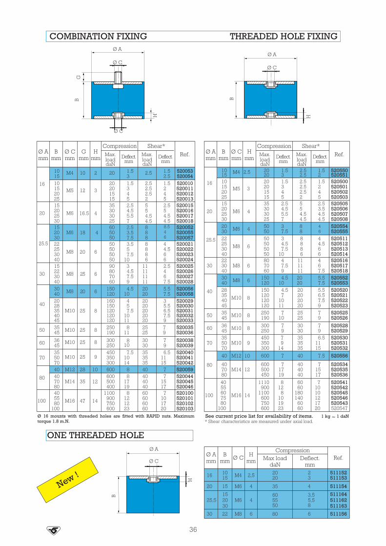
COMBINATION FIXING THREADED HOLE FIXING
36
Ø 16 mounts with threaded holes are fitted with RAPID nuts. Maximumtorque 1.8 m.N.
See current price list for availability of items. 1 kg � 1 daN* Shear characteristics are measured under axial load.
Gmm
Max.loaddaN
Deflect.mm
Compression Shear*
Ref.Ø Amm
Bmm
Ø Cmm
M4 10 520053520054
16
1015
Compression Shear*Ø Amm
M5 320201515
2.52.52.52
520500520501520502520503
16 10152025
1.5345
M6 4
35303025
2.54.55.57
554.54.5
520505520506520507520508
20
15202530
M8 6
50505050
34.57.5
10
8886
520511520512520513520514
22253040
1.52452.53.54.54.5
44.566
20
Max loaddaN
Hmm Deflect.
mm
CompressionRef.
Ø Amm
Bmm
M4 2,5 2020
23
51115251115316 10
15
Ø C
Ø A
H
B
New !
ONE THREADED HOLE
Ø C
Ø AØ A
Ø C
Ø C
HH
BG
B

Gmm
1016.5252020253545
1419284444607076
37
DIABOLO MOUNTS
ASSEMBLY
See current price list for availability of items. 1 kg � 1 daN* Shear characteristics’ are measured under axial load.
Ø Amm
12.520405757608095
M5M6
M10M8M8
M10M14M16
0.31.63.159.5
19.538.550
312304075
150300400
1.42.555589.59.5
0.532.57
12305570
1.254.556
109.58
521300521201521403521571521572521602521801521951
Bmm
Scm²Ø C
Compression Shear*
Ref.MaxLoaddaN
MaxLoaddaN
Deflec-tionmm
Deflec-tionmm
Compression
Compression/Shear Shear
The fixing holes for the Radiaflex mountsshould have a chamfer with a depth equalto the pitch of the thread.Ex. 521401: M10 x 150 chamfer = 1.5 mm
521951: M16 x 200 chamfer = 2 mm
Ø C
ØC
Ø A
P
F
S
P
GB
G
(cm²)
Scm²
Depthof
threadmm
Ø Amm
80 60 M14 15.5 38.5 250 5 70 8 521802
Bmm
Ø C
Compression Shear*
Ref.MaxLoaddaN
MaxLoaddaN
Deflec-tionmm
Deflec-tionmm
Also available with Ø 30 locators on each end, 3 mm thick allow M14 threaded holes:

PAULSTRADYN®
•Better than 90% isolation at 1.500 rpm(25 Hz).
•Constant height over wide load range.•Stabilised characteristics during Service Life.•Simple to fit.•400 hours protection against salt spray*.•Design.
* When mounted according to the recommendations given inthe catalogue.
New formula SILTECH- Low increase of stiffness with frequency- Low creep
ADVANTAGES
Finite element modeling
Natural frequency :• axial 7 Hz• radial 3 to 5.5 Hz
38
New !

3
Anti vibration isolation for static equipment :- rotating machinery such as fans, air-conditioning, pumps, compressors, generator sets.- pipework, ceilings, transformers, electrical enclosures.
APPLICATIONS
DIMENSIONS
39
* : Height, unloaded 40 mm, under load 32 mm (see Technical Characteristics).NL : Nominal static load with mounting under axial compression.
47
12401
2
2
2
2
80
100160200260
2
Designation
Paulstradyn 47
12
Paulstradyn 203050
Paulstradyn 70100130
Paulstradyn 160200260
Paulstradyn 325400500
Paulstradyn 640820
10501350
Ref.
533701533702533703
533704533705533706
533707533708533709
533710533711533712
533713533714533715
533716533717533718533719
Ø A
150
200
B* Ø C D E F G H Ø I J N
Dimensions (mm)Nominalload
NL (daN)
203050
70100130
325400500
640820
10501350
Fig.
60
40
40
40
40
40
40
M10
M12
M16
M6
M6
M8
124
182
240
52
76
100
10.2
12.2
14.2
6.2
6.2
8.2
16.2
20.2
24.2
6.2
8.2
12.2
2.5
2.5
2.5
4.5
5.5
152
214
280
64
90
122
104
154
204
44
64
84
68
116
159
12
32
48
10
10
20
6
6
12
Ø C
Ø I
Ø A
F
D
E G
HEG
J
B
N
J
N
B
Ø A
Ø I
Ø C
Fig. 1
Fig. 2

40
TECHNICAL CHARACTERISTICS
The vibration attenuation and height characteristics under nominal load are stabilised after onemonth under load at 20°C.
Common characteristics • Natural axial frequency 7 Hz, with nominal load.• Natural radial frequency 3 to 5.5 Hz.• Maximum displacement :
- axial : 12 mm.- radial : ± 10 mm.
Height under load
Temperature
Other characteristics*
Operating temperature : - 20°C to + 70°C.
• Good dynamic performance at high frequency.
• Withstands fatigue and shocks.
• Reduced creep.
* Detailed Technical Characteristics can be sent on request. Askus for details.
AL NL
= 0.8
AL NL
= 0.7
AL NL
= 0.9
AL NL
= 1
900 1500 2100 2700 3300 3900 4500 5100 5700
20
14
10
80
60
100
90
80
70
60
5010 20 30 40 50 60 70 80 90 100AL Actual load____ = Ratio _______________
NL Nominal load
Vibration attenuation Rotating speed (rpm)
Excitation frequency (Hz)
Att
en
uati
on
co
eff
icie
nt
(%)
Att
en
uati
on
(d
B)
Stabilised height vs load
AL/NL ratio (actual load/nominal load)
He
igh
t un
de
r lo
ad (
mm
)

Diameter K(mm) M6 M8 M10torqueN.m. 2 5 12
M12
20
Note : Do not paint the mountings after fitting.
Alternative mounting
Standard mounting
Recommended torque
① machine base or footdimensions > Ø M*
② supporting structure (floor)dimensions > base of mounting F x H* (referpage 39)
③ screw Ø C**
④ screw Ø K, a washer is required between the screwhead and the PAULSTRADYN*
⑤ screw Ø K, a washer is required between thescrew head and the PAULSTRADYN*
Note : * to ditribute the load and resist corrosion** nuts and screws grade 4.6 minimum.
41
MOUNTING
ON CONCRETE ON CHASSIS
Fig. 1
①
⑤
②
③ ④
25 M
ax
25 M
ax
Ø K
Ø M
Paulstradyn references
Dimensions (mm)
∅ KFig. 1
M5M5M6M8
M10M12
2740464799
127
14345070
118162
∅ L maxFig. 2
∅ M maxFig. 1
Référencecoupelle
(en option)
342919342356342733342734342353342354
533701, 533702, 533703533704, 533705, 533706533707, 533708, 533709533710, 533711, 533712533713, 533714, 533715
533716, 533717, 533718, 533719
Protective cap(optional - see table)
Ø L max
Mounting and cap references
Fig. 2

STABIFLEX
The STABIFLEX mounting comprises a conical rubber section bondedbetween inner and outer metal parts.
• Centre axis with threaded hole.• Square (4 holes) or diamond base (2 holes) with clearance hole.• Bonded natural rubber, anti-slip bead.• Cup to protect the rubber and distribute the load.
The design of the STABIFLEX mounting gives the following basiccharacteristics :
• Axial elasticity two or three times higher than radial elasticity.• The rubber works in shear/compression.• Progressive buffer against shocks or accidental overload.• Anti-slip (may be placed directly on the ground).
Advantages :• The machine may be placed with its mountings directly on the
ground.• Speed of fixing.• Easy movement of suspended machinery.• Rubber protected against harmful liquids.• Extensive range : 3 hardnesses of rubber for 5 existing types,
allowing the mounting to be optimised as a function of the load andforcing frequency.
• May be used with an anti-rebound washer.
Recommendations :• In order not to affect the performances of the mounting system, all
external connections must be flexible.• STABIFLEX mountings must be fitted so that the vibration input is in
the axial direction.(1) Natural frequencies with max/min loads, see : OPERATING CHARACTERISTICS.
DESCRIPTION
OPERATION
(1) Natural frequency :6 to 11 Hz
42

DIMENSIONS
OPERATING CHARACTERISTICS
43
STABIFLEX - diamond base STABIFLEX - square base
* Part identified by the letter “R” (reinforced) See current price list for availability of items.
Ø E Ø E
B
F
F
D
D
D F
XX X’
X’
J
Ø A Ø A
Ø CØ C
B
J
Nominalstatic load
daN
Deflectionmm Reference Hardness
10 - 4215 - 6020 - 93
30 - 12540 - 16550 - 21065 - 260
3.533.543.553
530603530603530613530603530613530622530613
45604575604575
Nominalstatic load
daN
Deflectionmm Reference Hardness
65 - 27595 - 380
110 - 450175 - 700
250 - 1000325 - 1300450 - 1800
4.53.588888
530622530622530642530642530652530652530652
60754560456075
Type Reference Hardness Ø Amm
Bmm Ø C D
mmE
mmF
mmJ
mmWeight
g
Diamond base 530603530613
45.60.7545.60.75
6984
4151
M12M12
98115
911
114137
67
250450
Square base530622530642530652*
45.60.7545.60
45.60.75
100133133
527171
M12M16M16
90114114
111313
114144144
799
100023002700

ASSEMBLY
LOAD/DEFLECTION CURVES IN AXIAL COMPRESSION
44
All our mountings are identified by conventional markings, either a paint spot or figuresindicating the hardness : grey = hardness 45, green = hardness 60, blue = hardness 75.
• Fixing with anti-rebound washer- The anti-rebound washer (not supplied) is fixed to the lower side of the centre axis.- In this case, do not forget to fit a spacer.
Spacer thickness required :
530603 h : 2 mm
530613 h : 4 mm
530622 h : 7 mm
530642 h : 14 mm
530652 h : 14 mm
• Standard fixing methods
h

STABIFIX®
STABIFIX® AR
The STABIFIX and STABIFIX AR (anti-rebound) are made of a rubberring bonded to two metal shelves. The anti-rebound function isintegrated with the STABIFIX AR version.
• Upper part with a smooth or a threaded hole (depending on version).• Diamond base (2 holes) or square base (4 holes) for the lower fixing
(2 holes).• Natural rubber bonded.
The design of STABIFIX gives the following basic characteristics:• Axial elasticity greater than radial elasticity.• The rubber works in compression/shear.• Progressive buffer against shocks or accidental overload.
Advantages:• Speed of fixing.• Easy movement of suspended machinery.• Rubber protected against harmful fluids.• Extensive range: 3 hardnesses of rubber allow the mounting to be
optimised as a function of the load and input frequency.
Recommendations:• In order not to affect the performances of the mounting system, all
external connections must be flexible.• STABIFIX and STABIFIX AR (anti-rebound) mountings must be fitted
so that the vibration input is in the axial direction.
(1) Natural frequencies with max/min loads, see: OPERATING CHARACTERISTICS.
DESCRIPTION
OPERATION
(1) Natural frequency:7 to 12 Hz
45
New !

DIMENSIONS
46
All our mountings are identified by conventional marking indicating the hardness.
530170530175Square base
Type Reference Hardness Ø Amm
Bmm Ø C D
mmE
mmF
mmJ
mm
Diamondbase
530181530184530185
45.6045.6045.60
82110101
354238
M10M16M16
110144144
111414
135175175
333
Gmm151515
7070
170170
Ø A1mm608781
118118
6363
24.5M20
150150
1313
184184
44
See current price list for availability of items.
Nominalstatic load
daN
Deflectionmm Reference Hardness
30 - 7570 - 160
110 - 220130 - 270180 - 380230 - 480
76.57.54.57.54
530181530181530184530185530184530185
456045456060
1000 - 20001000 - 2000
55
530170530175
7070
OPERATING CHARACTERISTICS
Ø A1
Ø A
Ø C
Ø A
Ø A1
Ø C
D
G E
Ø E
J B
B
B
J
J
F
DF
Ø A
Ø A1
Ø C
1 kg � 1 daN
STABIFIX ARanti-rebound
530181 - 530184 - 530185

TRIAXDYN
This anti-vibration mounting comprises two elastomers which areassembled into a casting and pre-loaded.
The mounting is designed to offer :• a large deflection (in axial),• different stiffness in three axis,• built-in stops to limit movement in all directions.
Note : The mount body can be modified to offer alternative interfacedimensions providing the internal interface with the elastomer ismaintained.
DESCRIPTION
47
This mounting has been designed to isolate engines or cabs in fixed ormobile applications with a high level of isolation and shock protection.Its compact design enables fail safe suspension of loads from 150 to280 kg.
It is suitable for :• Engine mounting.• Cab mounting.• Equipment mounting.
APPLICATIONS
New !

48
OPERATING CHARACTERISTICS AND DIMENSIONS
• Nominal load :- 150 to 280 kg.Possibility to extend, on request, the load rangeup to 350 kg.
• Different stiffness in three axis (for a hardness50) :- Axial on Z : 500 N/mm,- Radial on X (in direction of voids) : 350 N/mm,- Radial on Y (at 90 deg. to voids) : 500 N/mm.The geometry of the part provides low dynamicstiffness in the vertical dimension.
• Maximum deflection :- Axial : ± 10 mm, ± 4 g,- Radial : ± 6 mm, ± 2.5 g.
• Operating temperature :- up to + 80°C.
• Salt spray protection 400 h. for external alumi-nium metalwork.
Ø B
48.7
5
Ø 48
Ø A
28
9
133
Ø 1
08
15818
.5
C
12.5
X
Y
Z
66 u
nloa
ded
Mounting :
ReferenceØ Amm
Ø Bmm
Cmm
905233 12.4 94 128

ENGINE MOUNTINGS
This engine mounting is made of one conical elastomeric elementenclosed in a cast iron assembly. A built-in adjustable stop limits thevertical and lateral displacement during shock. This mount is availablein four different alternatives depending on the type of upper fixingneeded.It can be supplied with or without levelling system and with a threadedhole or a threaded stud.
This mount has been designed to suspend fixed or mobile generatorswhich require a high level of vibration isolation and shock protection.The load per mount varies from 600 kg to 2300 kg. This load range iscovered by 5 different variants (12 to 16) clearly identified by acoloured marking (see table).
This mount is available in four different alternatives depending on thetype of upper fixing needed:
• 905201: No levelling system - M24 x 3.00 threaded hole• 905202: Built-in levelling system - M24 x 3.00 threaded hole• 905203: No levelling system - M24 x 3.00 threaded stud• 905206: Built-in levelling system - M24 x 3.00 threaded stud
Note: Please refer to the drawings overleaf for more details on thedifferent types of mounts.(1) Natural frequencies with max/min loads, see: OPERATING CHARACTERISTICS.
DESCRIPTION
OPERATION
(1) Natural frequency:6 Hz
49
New !

50
OPERATING CHARACTERISTICS AND DIMENSIONS
Ø 18
190
230
133
unlo
aded
160
max
imum
hei
ght
12
140
180
R 20
M24 x 3.00
Ø 96
• Load range :Please refer to the chart below for the different variants and their colour marking.
• Deflection under static load :8 to 10 mm which gives a natural frequen-cy around 6 Hz.
• Maximum displacement :Vertical (Axial) : ± 6 mm.Lateral (Radial) : ± 5 mm.
• Ultimate load :Vertical (Axial) : ± 4 g.Lateral (Radial) : ± 3 g.
• Operating temperatures :- 10°C up to + 70°C.
• Unit weight :11.5 to 12.8 kg (depending on the variant).
Load range Variant Color
600 - 850 kg850 - 1150 kg
1100 - 1450 kg1400 - 1900 kg1700 - 2300 kg
1213141516
WhiteYellowGreenBlue
Purple
Reference 905202
Ref. 905201 Ref. 905202 Ref. 905203 Ref. 905206
ASSEMBLY
The installation of these mounts and the adjustments of their limit stops once loaded aredetailed in an assembly procedure supplied with the mounts.

S.C. MOUNTING
The S.C. mounting comprises an annular section bonded between theinner tube and outer housing.The outer housing has a mounting flange (4 different types).
The design of the S.C. mounting gives the following basic characte-ristics :
• Axial elasticity four times higher than radial elasticity.• The rubber works in shear.• Progressive buffer against shocks or accidental overload, provided
that a large metal washer is used to bear against the rubber dome.• Can be used as a fail safe assembly when fitted as in figure 1.
Advantages :• Extensive range : 3 hardnesses of rubber for 20 existing types,
allowing the mounting to be optimised as a function of the load andexciting frequency.
Recommendations :• In order not to affect the performance of the mounting system, all
external connections must be flexible.• S.C. mountings must be fitted so that the vibration input is in the axial
direction.
(1) Natural frequencies with max/min loads, see : OPERATING CHARACTERISTICS.
DESCRIPTION
OPERATION
(1) Natural frequency :6 to 30 Hz
51

Reference
With fixing holes Without fixing holes
Ø Amm
202637.537.549.149.155.755.757.26566.5767687.586
118118118170170
6.28
12.112.112.212.218.218.218.220.220.222.222.240.240.260.260.260.28080
3.25.2----8.28.2----
10.58.58.58.58.58.5
10.510.510.510.512.212.2
312.51824203127393929474249476336669695
113
112840514760557070759390
110100120
98140170167185
1926----6969----867895
100100114104145145145204204
25364848727270709090
107112112127120164164164230230
412
88
12121018181818181820202222223030
840
110130190290370480500560780880960
1300150022003000380071007700
711.51818181819191928282828.533334646465353
11.5222233333333344455
Bmm
Ø Cmm
Dmm
Emm
Fmm
Gmm
Hmm
Jmm
Kmm
WeightgTYPE
S.C. 000S.C. 00S.C. 01S.C. 02S.C. 10S.C. 11S.C. 20S.C. 21S.C. 21S.C 30S.C. 31S.C. 40S.C. 41S.C. 50S.C. 51
S.C. 70 red.S.C. 70S.C. 71S.C. 80S.C. 81
531201531301
----
531216531611
----
531240531259531261531714531327531939531947531933531932531931531940531941
Fig. cFig. c
----
Fig. dFig. d
----
Fig. dFig. bFig. dFig. dFig. dFig. dFig. bFig. bFig. bFig. bFig. bFig. b
----
531401531402
----
531701531702
------------------------
----
Fig. aFig. a
----
Fig. aFig. a
------------------------
See current price list for availability of items.
DIMENSIONS
52
Fig. a Fig. b Fig. c Fig. d
Ø C
HG J
B
Ø A
K
Ø EØ E D
F KK
D
F
F
E
K
D
F
Ø C
HG J
B
Ø A
Ø C Ø C
H H
G GJ J
B B
Ø A Ø A
F

OPERATING CHARACTERISTICS
LOAD/DEFLECTION CURVES IN AXIAL COMPRESSION
53
NominalstaticloaddaN
Deflect.mm Reference Hard.
35-15035-15040-17545-18045-19045-19055-22560-24060-25060-25060-25060-25075-30080-32080-32585-35090-36095-380
100-400105-420
1.53523353.5225524.54.53.54.534.52
531611531701531259531701531240531702531714531259531240531702531261531327531259531714531939531261531327531714531947531261
4560754560754560454575604560457575604545
7560457560604560757545457560456060754575
NominalstaticloaddaN
Deflect.mm Reference Hard.
1-62-8
2-105-207-30
10-4010-5015-6515-6515-7020-8020-8520-85
25-10025-10025-11030-12030-12030-13530-135
10.80.51.51.20.82.51.82.541.51.8433.51.5233.53.5
531201531201531201531301531301531301531401531401531402531216531401531402531611531216531701531402531216531611531240531702
NominalstaticloaddaN
Deflect.mm Reference Hard.
110-440110-450110-450135-550135-550150-600165-670175-700210-850225-900275-1100275-1100310-1250350-1400400-1600450-1800525-2100575-2300650-2600
3.536.52.53.552.56.56.5535
113
118.58.555
531939531327531933531939531947531933531947531932531931531932531932531931531940531931531941531940531941531940531941
60754575606075454560756045754560607575
1 kg � 1 daN

ASSEMBLY
54
Fig. 1 - Fixing between theequipment and a metallic chassis(failsafe in mobile applications).
Fig. 4
Fig. 2 - Fixing between twobrackets onto a vertical surface(non failsafe).
Fig. 6 - Two mountings fixed face toface. Provides twice the deflectionunder the same load.
Fig. 3 - Fixing between the equip-ment and concrete (using locatingrings).
• Mounting in tandem
• Standard fixing
• Reversed fixing
Fig. 5 - Fixing between inertia baseand foundation. The inertia baseincreases the suspended mass andthus reduces the amplitudes of thevibrations as well as lowering thenatural frequency.
staticchassis
staticchassis
Load
Load

EVIDGOM®
The EVIDGOM mounting is formed from two thick conical membranes,joined at their bases to create a highly elastic mounting.There are three variations :
• All rubber EVIDGOM.• EVIDGOM with bonded fixing.• EVIDGOM with a diamond or square mounting plate (fixing plate
supplied as a separate kit).
The design of the EVIDGOM mounting gives the following basiccharacteristics :
• A very high axial elasticity.• Very low natural frequency (a few Hertz).• Progressive buffer against shocks or accidental overload.
Advantages :• As the load/deflection curve has a point of inflection, a suspension
may be designed to have a sub-tangent greater than the staticdeflection.
• The elastomer used provides intrinsic damping with a correspondingability to absorb energy which gives appreciable advantages overmetallic springs.
Recommendations :• The selection of a low natural frequency (large deflection) must not be
allowed to endanger the stability of the suspension (tall equipment).• In certain cases (use under maximum load) the use of side stops is
recommended.
(1) Natural frequencies with max/min loads, see : OPERATING CHARACTERISTICS.
DESCRIPTION
OPERATION
(1) Natural frequency :2.5 to 7 Hz
55

Evidgomreference
Dmm
Fig.
810780810766810768810769810773810784810779810770810775810776
98/102124/128124/128178/182178/182178/182178/182178/182
170170
Emm
8.210.210.210.210.210.210.210.210.510.5
Fmm
117158158214214214214214200200
Gmm
65110110150150150150150
--
Hmm
5556666688
337566337567337567337568337568337568337568337568337569337569
aaaaaaaabb
Fixingpack
reference
DIMENSIONS
56
Fig. 1 Fig. 2 Fig. 3
PP
BB B
Ø T3 x Ø TØ W
Ø AØ A
Ø A
Ø C 1
Ø CØ C 1
C 3 Ø C2Ø C2
Ø W
Lower fixing plate
Fig. bFig. a
D
G D F
E
D
H
Ø EF
See current price list for availability of items
Ø Amm
Bmm All rubber Fig. With
fixings Fig.Ø C
Ø C1mm
Ø C2mm
Ø C3mm
Ø Wmm Ø T
Pmm
344050608595
108120140125140140155188250350
25557040709090
110120140
9056
150180230290
810002810003810005
810006810008810009810012810013810014810019810020810015810016
--
111
1111111111--
810780810766810768810769
810773810784810779810770810775810776810733810736
2222
22222233
M10M16M16M16
M16M16M16M16M16M24
--
81414
202020202525283025407085
8141425303030304030123030407085
25303034
352528303040
40606070
707070709090
150196
M6M8M8
M10
M10M10M10M10M14M14
6 X M248 X M24
688
10
1010101014144040
Evidgom reference
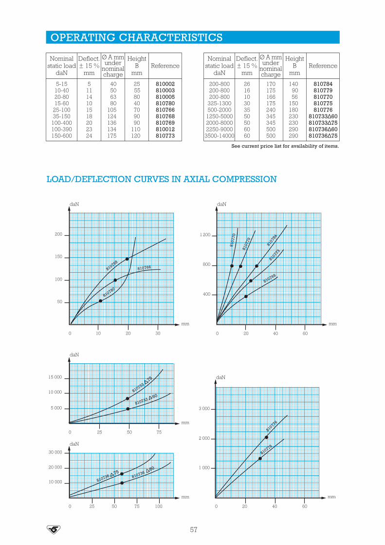
LOAD/DEFLECTION CURVES IN AXIAL COMPRESSION
57
OPERATING CHARACTERISTICS
Nominalstatic load
daN
Deflect.± 15 %
mm
Ø A mmunder
nominalcharge
HeightB
mmReference
5-1510-4020-8015-60
25-10035-150
100-400100-390150-600
51114101518202324
40506380
105124136134175
25558040709090
110120
810002810003810005810780810766810768810769810012810773
Nominalstatic load
daN
Deflect.± 15 %
mm
Ø A mmunder
nominalcharge
HeightB
mmReference
200-800200-800200-800
325-1300500-2000
1250-50002000-80002250-9000
3500-14000
261610303550506060
170175166175240345345500500
1409056
150180230230290290
810784810779810770810775810776
810733∆60810733∆75810736∆60810736∆75
See current price list for availability of items.

S.T.C.
The S.T.C. mounting comprises a rubber ring bonded to a central tube.
• Inner tube : mild steel.• Bonded rubber in the form of a ring at the top with a collar below
which is used for fixing.
The design of the S.T.C. mounting gives the following basiccharacteristics :
• The rubber works in compression.• Anti-rebound.• Can be used as safety mounting.
Advantages :
• Simple to fix.• Simple and economical.• Extensive range of loads.
(1) Natural frequencies with max/min loads, see : OPERATING CHARACTERISTICS.
DESCRIPTION
OPERATION
(1) Natural frequency :10 to 25 Hz
58

DIMENSIONS
OPERATING CHARACTERISTICS
ASSEMBLY
59
Reference Ø Amm
Bmm
Ø Cmm
Ø Dmm
Emm
Ø Fmm
Gmm
539887539190539886539191
* 539920539951
20.631.534.341.13856.6
17.525.43544.52350.8
101313161620
27.744.550.863.56495
5.610.413.515.71625.4
20.631.534.341.138.556
81016191920
* This S.T.C. is mounted in pairs : see Fig. 2. See current price list for availability of items.
Reference HardnessNominal
static loaddaN
Deflectionmm
539887
539190
539886
4560
4560
6075
8-3510-50
15-7525-100
35-15080-330
0.70.7
1.21.2
1.21.2
Reference HardnessNominal
static loaddaN
Deflectionmm
539191
539920
539951
6075
4575
4565
60-250125-500
100-400250-1000
175-700250-1000
22
21
33
Fig. 1 Fig. 2 (For 539920)
Ø D
Ø F
Ø C
Ø A
B
G
E

STOPS
There are several types of stops :
• Cylindrical or DIABOLO stops.• Conical progressive stops.• LEVAFLEX progressive stops with central cavity.• EVIDGOM stops.
The design of the PAULSTRA elastic stops gives the following basiccharacteristics :
• Highly deformable allowing high energies to be absorbed.• Progressive absorption of energy due to the carefully designed
shape.
Advantages :• By comparison with rigid stops, PAULSTRA elastic stops are quiet and
avoid hammering and deterioration of equipment.
Recommendations :• The stops must be fitted so that, on impact, the axis of the stop is
perpendicular to the contact surface.• On impact, the external diameter of the stop increases : this must be
allowed for when fixing.
DESCRIPTION
OPERATION
60
See : Supports andBump stops
Cylindrical stop Conical progressive LEVAFLEX progressive EVIDGOM stopstop stop

80
2530407080
M14
1100950600500450
68
101719
33.0038.0030.0042.5043.00
513801511830511840511870511880
4535353535
1 -
60253645
M10400300250
69
11
12.0013.5013.70
511625511635511645
25 1 -
70355070
M10450350300
91214
20.0021.0021.00
511735511750511770
25 1 -
50253545
M10300250190
69
11
9.0011.2010.00
511525511535511545
25 1 -
30
402025354045
M10
160150120120120
568
1011
4.004.504.806.006.60
511450511401511452511454511456
25 1 -
15223040
M8
90807060
3.5689
1.502.402.802.70
511308511310511312511314
25 1 -
10151922253040
M8 20
80605550505050
23.54.55.568
10
0.801.001.201.301.502.002.50
511265511270511251511275511280511285511290
1 -
22 M8 80 6 2.40 511156- 2 6
25.5
ReferenceGmm
Ø Amm
Bmm Ø C
ChargemaxidaN
Deflect.mm
EnergyJoulesFig. H
mm
4.606.00
511157511161
120120
710
3040 M8 20 1 -
354
18181818
---
10152030152030
M6
Repetitive shocks
Deflect.mm
1
2
Wghtg
Deflect.mmReference
Exceptionalshock
Energyjoules
Max.staticloaddaN
ReactiondaN
8.515202530
M6 16.5
4035303025
0.300.700.700.800.80
1.5455.57
511200511215511220511225511230
-
1111222
80605050605550
0.801.001.202.001.001.202.00
23.5583.55.58
----444
15 M6 - 0.704 511154
Fig.
10151015
M4 -1122
202323
0.200.300.200.30
511150511151511152511153
--
2.52.5
Hmm
DIMENSIONS AND OPERATING CHARACTERISTICS
61
CYLINDRICAL STOPS
CONICAL PROGRESSIVE STOPS
See current price list for availability of items.
See current price list for availability of items.
See current price list for availability of items.
DIABOLO STOPS
∅ Amm
Bmm Ø C
Max.loaddaN
Deflectmm
EnergyJoules Reference
12.5
16
20
25.5
1013.51520
10152025
M5
M5
Gmm
10
12
1
1
121110
8
20201515
22.533.5
0.120.130.160.14
0.200.300.300.30
2345
511110511128511115511125
511292511294511296511298
511158511155511159511160511164511162511163
Ø Amm
Bmm Ø C G
mmEnergyJoulesReference
25.530305050505050506060727295
202513.52520253525152562253045
1930305050646458584040585880
M8M8M6
M10M8
M10M8
M10M8
M10M14M10M12M16
366
30304040373727275050
120
815152525323228281818262637
100140140340340370370400400550550550550
1100
918189090
120120110110
7070
150150350
Wghtg
2037308575
150150130120140200290300750
512251512307512301512515512501512516512502512517512503512608512601512700512721512951
Ø Amm
Bmm
Ø CG
mm
Max.instant.
loaddaN
Deflect.mm
2020253035
5757608095
4242576570
M8M8
M10M14M16
100200350800
1000
1012151618
4075
150300400
45.589.59.5
EnergyJoules
126
1520
6080
190500790
511571511572511601511801511951
Scm²
59.5
19.538.550
G
Ø CØ A
B
G
CA
BG
Ø C
Ø A
S (cm²)B
-
-
Ø C
Ø A
H
B
Fig. 1 Fig. 2 New rangeRADIAFLEX

Bmm
Ø Cmm
DmmReference
6990
106132168
Ø Emm
8.58.5
111113
Ø Gmm2030404560
Hmm
5668
10
85110130160200
8.512.5192328
Weightg600
1200200030007000
514085514110514130514160514200
Amm
85110130160200
LEVAFLEX PROGRESSIVE STOPS
EVIDGOM STOPS
EnergyJoules
170280330550600650
1050120013002200
Correspondingdeflection
mm40405050656075907085
ReactiondaN
Exceptionalshock
energyJoules
1200170018003400280030004500400060007800
500850
10001500180019003000360039006600
Referencehardness
514085/60514085/75514110/60514110/75514130/60514130/75514160/60514200/60514160/75514200/75
Repetive shocks
EnergyJoules
31100110180350360400300600
1050250071009500
130001750021000290004100050000
Correspondingdeflection
mm3050456775658570759090
150200130175200250200250
ReactiondaN
Exceptionalshock
energyJoules
190580600750
125014001500
900162523755500
110009500
180001900025000350007000055000
95300330540
105011001200
------------------------
Referencehardness
810644810645810666810642810653810655810669810784810775810776
810733/60810732/60810731/60810732/75810731/75810735/60810734/60810735/75810734/75
Repetive shocks
62
Stopreference
810642810644810645810653810655810666810669810731810732810733840734810735810775810776810784
810022810004810035810023810025810046810029
----------
810015810016810014
Fig.
112112233333111
Bmm Ø C Ø C1
mmØ C2mm
Ø Dmm
Ø Aunder load
mm
11472
100140142
98155360380370445500202256168
1205593
130132
90150400315230500395150180140
M16M10M16M16M16M16M16
6 X M246 X M246 X M248 X M248 X M24
M16M24M16
All rubberEvidgomreference
Ø Amm
855566
100110
76110250250250350350155188125
201420202020207070708585254030
301414303014307070708585403025
--------------
150150150196196------
NOTE: The values are given for test conditions with an impact speed of 1 m/s. Consult us for speeds that are much higher.
See current price list for availability of items.
Fig. 3
A
Ø C
Ø D
C 1
B
C 2
D
A
DH
BA
E
C
G
Fig. 2Fig. 1
B B
A A
C 2C 2
CC
1 kg � 1 daN
1 kg � 1 daN

63
DEFLECTION CURVES AND ENERGY VALUES FOR PROGRESSIVE,LEVAFLEX AND EVIDGOM STOPS (Pages 61and 62)
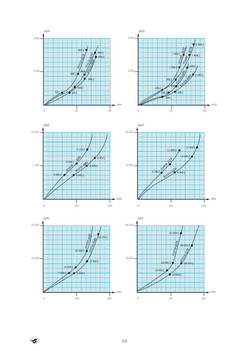
64

NIVOFIX®
The NIVOFIX mounting is an adjustable equipment foot comprising acircular disc bonded to a protected elastomer base. An adjustementscrew is fitted into the assembly.
The elastomer base has anti-slip ridges.
The design of the NIVOFIX mounting gives the following basiccharacteristics :
• Accurate adjustment of the mounting to correct the equipment’sseating (adjustment screw, correction of altitude).
• Absorbs high frequency vibrations.• Corrosion resistant (nitrile elastomer, protective shroud, galvanised
metallic parts).• Anti-slip sole (no need to fix).
Advantages :• Speed of fixing.• Simple removal of the equipment.• No shimming.
DESCRIPTION
OPERATION
See Vibrachocmetallic range :
V43 - V44 - V45 - V46
65

Studlenght
mm120200250300300
DIMENSIONS
OPERATING CHARACTERISTICS
APPLICATIONS
66
See current price list for availability of items.
ReferenceStainless
steel
ReferenceSteel
Amm B maxi = B mini + adjustment
B mmØ C
mini maxi
G mm Weightg
530815530825530835
530810530820530830530840530850
6588
133200260
31.546587083
26.533465865
513121218
M12M16M20M24M24
105114130145158
110127142157176
280690
18205250
10000
Reference
530810530815530820530825
Nominalstatic load
min - max in daN100 - 600100 - 600
325 - 1300325 - 1300
Deflectionmm
1 - 3.51 - 3.52 - 42 - 4
Reference
530830530835530840530850
Nominalstatic load
min - max in daN
Deflectionmm
2 - 42 - 4
1.5 - 32 - 4
650 - 2600650 - 2600
1500 - 60003000 - 12000
NIVOFIX mountings are used for all equipment requiring height adjustment.
Equipment already using NIVOFIX mountings:
• Vertical mill • Plane • Packaging machine• Mortiser • Horizontal mill • Test equipment• Multichuck drill • Lathe • Printing press• Sheet metal bender • Office equipment • Gear cutter• Polisher - accounting • Textile machinery• Press - computing
Ø C
G m
ax.
G m
in.
B m
ax.
B m
in.
A
1 kg � 1 daN
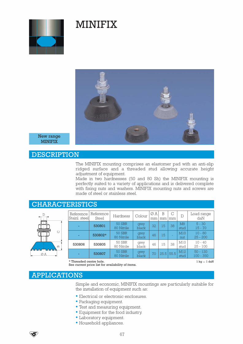
MINIFIX
The MINIFIX mounting comprises an elastomer pad with an anti-slipridged surface and a threaded stud allowing accurate heightadjustment of equipment.Made in two hardnesses (50 and 80 Sh) the MINIFIX mounting isperfectly suited to a variety of applications and is delivered completewith fixing nuts and washers. MINIFIX mounting nuts and screws aremade of steel or stainless steel.
Simple and economic, MINIFIX mountings are particularly suitable forthe installation of equipment such as:
• Electrical or electronic enclosures.• Packaging equipment.• Test and measuring equipment.• Equipment for the food industry.• Laboratory equipment.• Household appliances.
DESCRIPTION
APPLICATIONS
67
New rangeMINIFIX
Hardness ColourReferenceStainl. steel
ReferenceSteel
Load rangedaN
- 530801 50 SBR80 Nitrile
greyblack
Ø Amm
32
Bmm
15
Cmm
38
D
M8stud
5 - 3015 - 70
- 530802* 50 SBR80 Nitrile
greyblack 46 15 - M10
nut10 - 80
25 - 200
530806 530805 50 SBR80 Nitrile
greyblack 46 15 38 M10
stud10 - 40
25 - 100
- 530807 50 SBR80 Nitrile
greyblack 70 25.5 55.5 M12
stud50 - 120
100 - 350
CHARACTERISTICS
* Threaded centre hole. 1 kg � 1 daNSee current price list for availability of items.
D
Ø A
BC

TRAXIFLEX
The TRAXIFLEX mounting comprises two metallic U armatures joinedby two bonded rubber blocks.It is available in two versions : male/female and female/female.
The design of the TRAXIFLEX mounting gives the following basiccharacteristics :
• Rubber works in compression-shear.• The same deflection under nominal load for all types.• Positive safety in case of elastomer failure.
Advantages :• Economic solution for suppressing structure borne noise.• Several fixing methods.• High resistance to atmospheric exposure :
- galvanised armatures- chloroprene elastomer.
• Upper metallic part is shaped to simplify orientation while fixing.• Two hardnesses of elastomer to extend the choice of mounting as a
function of load.• Filtration of vibration and the attenuation of the consequent noise.• Allows movement due to thermal expansion.
(1) Natural frequencies with max/min loads, see : OPERATING CHARACTERISTICS.
DESCRIPTION
OPERATION
(1) Natural frequency :8 to 10 Hz
See Vibrachocmetallic range :VE101 - VE111VE112 - VE113
68

Reference
2 nuts
--------
535621535621535622535622
Deflectionmm Hardness1 screw -
1 nut
DIMENSIONS
OPERATING CHARACTERISTICS
ASSEMBLY
69
RecommendedloaddaN
4-184-187-307-30
10-5220-8020-92
30-136
444444444
535600535603535600
53560361**535611535611535612535612
4545606045604560
When fixing, ensure that all the TRAXIFLEX mountings are supporting the same load. It isnecessary to ensure that they are all the same distance from the fixing surface (ceiling, girder,plank...).TRAXIFLEX mountings can be used to suspend pipework: the whole assembly being fixed tothe ceiling.
• Suspending hot air ducts.• Suspending a fan unit and distribution ducts.• Suspending a hot air generator with continuous airflow.• Suspending an integral cased air conditioner.
1 kg � 1 daN
TRAXIFLEX mountings have been subjected to acoustic trials at the Centre Expérimental de Rechercheset d'Études du Bâtiment et des Travaux Publics which has given the P.V nr. 554.6.078.Note: For important loads, refer to solutions given page 30.** Elastomer resistant to fire M1(Suffix 11).
See current price list for availability of items.* Mountings ref. 535600 are fitted with a screw which can accept "ATLAS" collars.** The part 53560361 also exists with a longer stud, H = 17 mm in an elastomer resistant to fire M1(suffix 11).
Type
TR 12-30TR 12-30TR 12-30TR 40-80
TR 100-250
------
535621535622
535600*53560361**535603535611535612
Reference1 screw - 1 nut 2 nuts
Hard-ness
Amm
Bmm
Ø CG
mmH
mm
45-606045
45-6045-60
4747475574
3838384750
M7 x 1.50M6 x 1.00M6 x 1.00M8 x 1.25
M12 x 1.75
1616163040
717171317
B
H
Ø C
A G

BATRA RING
The BATRA ring comprises a rubber ring bonded to two metallicwashers one with a circular groove, the other with a mating circularridge which allows BATRA rings to be mounted one on top of another.
The design of the BATRA ring gives the following basic characteristics :
• Behaviour identical to that of a metallic spring plus damper.• Robustness :
- well behaved under shock.- removal of the risks of suspension collapse.
• Flexibility easily tailored by stacking BATRA rings.• Transverse creep limited by the two bonded armatures.
BATRA rings may be used :
• For making suspensions that are very flexible vertically and alsodamped by the natural properties of the rubber (road and railvehicles).
• For making very effective anti-shock buffers (wagons, cars, gantries).For special applications, where the quantities would justify custommanufacture, it is possible to supply Special BATRA rings either withonly one bonded lower armature or “all rubber”.For special cases of shock, there are Special BATRA rings withoverlapping, non-bonded, armatures.
(1) Natural frequencies with max/min loads, see : OPERATING CHARACTERISTICS.
DESCRIPTION
OPERATION
APPLICATIONS
(1) Natural frequency :7 to 22 Hz
70

45220300415540890750980
13601680151026004400
508086
100115140146146170170185250250
Ø Amm
541050541083541082541100541112541145541146541144541175541174541185541249541250
Reference
112727.528.5303520353550405059
1441.53232505555556060957070
3261656585
100.5100.5100.5115115140160160
4455
101010101010101010
5677
101010101010101010
2.5344555555555
1.5322333333333
Bmm
Ø Cmm
Gmm
Hmm
Jmm
R1mm
R2mm
Weightg
Staticcompression
Dynamiccompression
NominalloaddaN
Deflectionmm
LoaddaN
Deflectmm (1)
Ø Amaxi
Reference
50-20090-360
125-500175-700210-850
325-1300375-1500
0.833333.53
600110015002100250040004500
3.577779.57
5790
100115130150158
541050541083541082541100541112541145541144
Staticcompression
Dynamiccompression
NominalloaddaN
Deflectionmm
LoaddaN
Deflectmm (1)
Ø Amaxi
Reference
475-1900500-2000500-2000500-2000
1125-45001125-4500
1.135.34.54.55.5
5700600060006000
1350013500
2.59.5
14121213
158190190205282282
541146541175541174541185541249541250
DIMENSIONS
OPERATING CHARACTERISTICS
ASSEMBLY
The rings are centred using the grooves and ridges. To avoid play under no-load conditions, thestack should be pre-compressed by 3 to 10% of its height. It is also necessary to leave sufficientroom around the stack for the sideways expansion under load.
71
See current price list for availability of items.
(1) The instantaneous deflection indicated in this table is approximate as it depends on the impact speed. 1 kg � 1 daNIt is possible to use a metallic cushion for this application.
Ø A
G
Ø C R2 R2R1
B
H
JJ

BECA
The BECA mounting comprises one piece elastomer bonded to a topand bottom plate.• Top plate: smooth or threaded (welded nut) hole.• Bottom plate: Fixing lugs or direct bearing on the ground.• Bonded rubber.• Domed rubber ring.• Anti-slip bead or grooved anti-slip sole.• Removable protective top cover : protects the rubber and distributes
the load.
The design of the BECA mounting gives the following basiccharacteristics :• Transverse elasticity approximately the same as the axial elasticity
(equi-frequency).• Rubber works in compression.• Progressive buffer against shocks or accidental overload.• Anti-slip (may be placed directly on the ground).Advantages :• The machine may be placed (with its mountings) directly on the
ground.• Very slim.• Speed of fixing.• Simple removal of the assembly.• Extensive range: 3 hardnesses of rubber for 6 existing sizes, allowing
the mounting to be optimised as a function of the load and stimulationfrequency.
• A choice of 3 fixing styles.Recommendations :• In order not to affect the suspension of the machine, all external
connections must be flexible.• BECA mountings can be used for fixed, well-balanced rotating
machinery, otherwise a ballasting slab should be used.(1) Natural frequencies with max/min loads, see : OPERATING CHARACTERISTICS.Nota : BECA mountings can be replaced by PAULSTRADYN mountings.
DESCRIPTION
OPERATION
(1) Natural frequency :8 to 14 Hz
72

Nominal staticloaddaN
Deflectionmm
1-42-103-156-25
11-4511-4520-8022-90
30-120
22.53334.54.544
Type
Ø 40Ø 40Ø 60Ø 60Ø 60Ø 80Ø 80
Ø 100Ø 80
Hardness
456045607545604575
Nominal staticloaddaN
Deflectionmm
30-13040-16050-22060-25085-350
125-500200-825
310-1250
74476776
Type Hardness
4560756075456075
Hardness
Reference
Anti-slip base Diamond baseTypeSmooth
hole (fig. a)Smooth
hole (fig. b)Threaded
hole (fig. c)
Ø Amm
Bmm
B1mm
Ø Cmm
ØC1
Dmm
Ø Emm
Fmm
Jmm
Ø Mmm
Weightg
45.6045.60.7545.60.7545.60.7545.60.7545.60.7545.60.7545.60.7545.60.75
Ø 40Ø 60Ø 80
Ø 100Ø 100Ø 150Ø 150Ø 200Ø 200
------
533108--
533151--
533202--
----
533581--
533109--
533152--
533203
533641*533661533681
--533609
--533652
--533623
406080
100100150150200200
2024273027.541394644
1822.52528
25.538364240
--8.1
10.210.214.214.21818
M6M6M8
-M10
-M14
-M18
5276
100-
124-
182-
240
6.26.28.2-
10.2-
12.2-
14.5
6490
120-
148-
214-
280
222-2.5-4-5
191822222234344444
50140250420460
1220134027503030
Ø 150Ø 100Ø 100Ø 150Ø 150Ø 200Ø 200Ø 200
73
DIMENSIONS
OPERATING CHARACTERISTICS
* Ø 40, M6 - RAPID nut - max. torque 3 N.m. See current price list for availability of items.
BECA with anti-slip base BECA with lugs, smooth hole BECA with lugs, threaded hole
Section XX’ Section XX’ Section XX’
Fig. a Fig. b Fig. c
Ø M
ØC Ø C
Ø A Ø AØ C1
Ø M
Ø E Ø E
DF
X X X’ X’X
X’
B 1 B B1 B
J
1 kg � 1 daN

LOAD/DEFLECTION CURVES IN AXIAL COMPRESSION
ASSEMBLY
74
BECA mountings in tandem (to double the deflection)
All our mountings are identified by conventional markings, either a paint spot or figuresindicating the hardness : grey = hardness 45, green = hardness 60, blue = hardness 75.
Mounting axisBECA with
smooth hole
BECA with threadedhole (welded nut)
Anti-rebound (prestressed)
Slab
Casing withinaccessible
base
BECA Ø 100 BECA Ø 150 BECA Ø 200
BECA Ø 40 BECA Ø 60 BECA Ø 80

POLYFLEX
DIMENSIONS
OPERATING CHARACTERISTICS
(1) Natural frequency : 9 to 20 Hz
75
See current price list for availability of items.
(1) Natural frequencies with max/min loads, see : OPERATING CHARACTERISTICS.
Section XX’
A
CX X’
E
D
F
G
BH
Nominalstatic load
daN
Deflectionmm
1-51-72-8
2-103-154-185-207-30
3214352.53
Reference
532300532300532300532500532500532563532500532561
Hardness
4560754560457545
Nominalstatic load
daN
Deflectionmm
7-3010-4010-5010-5015-6015-6520-80
521.545.531.5
Reference Hardness
60607545756075
532563532561532561532750532563532750532750
Reference Ø Amm
Bmm
Ø Cmm
Dmm
Ø Emm
Fmm
Gmm
Hmm
532300532500532563532561532750
3050556075
1620232530
68
10.112.212.2
4066907695
6.18.28.28.5
11.0
5082
10695
118
813152025
1.52346

S.C.P. MOUNTING
DIMENSIONS
OPERATING CHARACTERISTICS
(1) Natural frequency : 9 to 15 Hz
76
See current price list for availability of items.
(1) Natural frequencies with max/min loads, see : OPERATING CHARACTERISTICS.
Reference Ø Amm
Bmm
Ø Cmm
Dmm
Ø Emm
Fmm
Gmm
Hmm
530120530220530420
7492
124
536394
101216
7290
114
91113
90114144
323660
334
ReferenceLoaddaN
70140300
345
120200500
2.535
175300800
22.54
58010002550
Deflect.mm
LoaddaN
Deflect.mm
LoaddaN
Deflect.mm
530120530220530420
HARDNESS45
HARDNESS60
HARDNESS75 Weight
g
Section XX’
A
C
X
G
X’
E
D
F
B
D F
H

ISOFLEX
The ISOFLEX mounting comprises two concentric metallic parts joinedby a bonded, perforated rubber ring.
The design of the ISOFLEX mounting gives the following basiccharacteristics :
• Elasticity approximately the same in all directions (equi-frequentmounting).
ISOFLEX mountings may be used for suspending any small measuringor recording equipment, mobile equipment, machine tool controls.
(1) Natural frequencies with max/min loads, see : OPERATING CHARACTERISTICS.
DESCRIPTION
OPERATION
APPLICATIONS
(1) Natural frequency :11 to 15 Hz
77

To avoid toppling or canting, the suspension should be designed so thatthe centre of gravity of the suspended equipment is close to thegeometrical centre of the suspension.
Fixing method
78
DIMENSIONS
OPERATING CHARACTERISTICS
See current price list for availability of items.
ASSEMBLY
All our mountings are identified by conventional markings, either a paint spot or figuresindicating the hardness:grey = hardness 45, green = hardness 60, blue = hardness 75.
Reference Hard.Ø Amm
Bmm
Ø Cmm
Dmm
Ø Emm
Fmm
Gmm
Hmm
Jmm
Weightg
552428552231552241
Fig.Type
RI.20I.30
abb
5045-6045-60
2825.438.1
810.315.9
4.24.26.2
3625.434.9
3.23.64.2
4431.844.5
44.27.3
31-
-4.37.3
91030
Nominalstatic load
daN
33
2.5
Deflectionmm Type Reference Hard.
RI.20I.20
552428552231552231
504560
0.25-10.50-20.75-3
Nominalstatic load
daN
Deflectionmm Type Reference Hard.
I.30
I.30
552241
552241
45
60
1-4
1.5-6
3
2
Fig. a Fig. b
Ø A
ØC
Ø E
Ø E
GH
B
D
D
F
FD
B
GJ
H
Ø A
Ø C
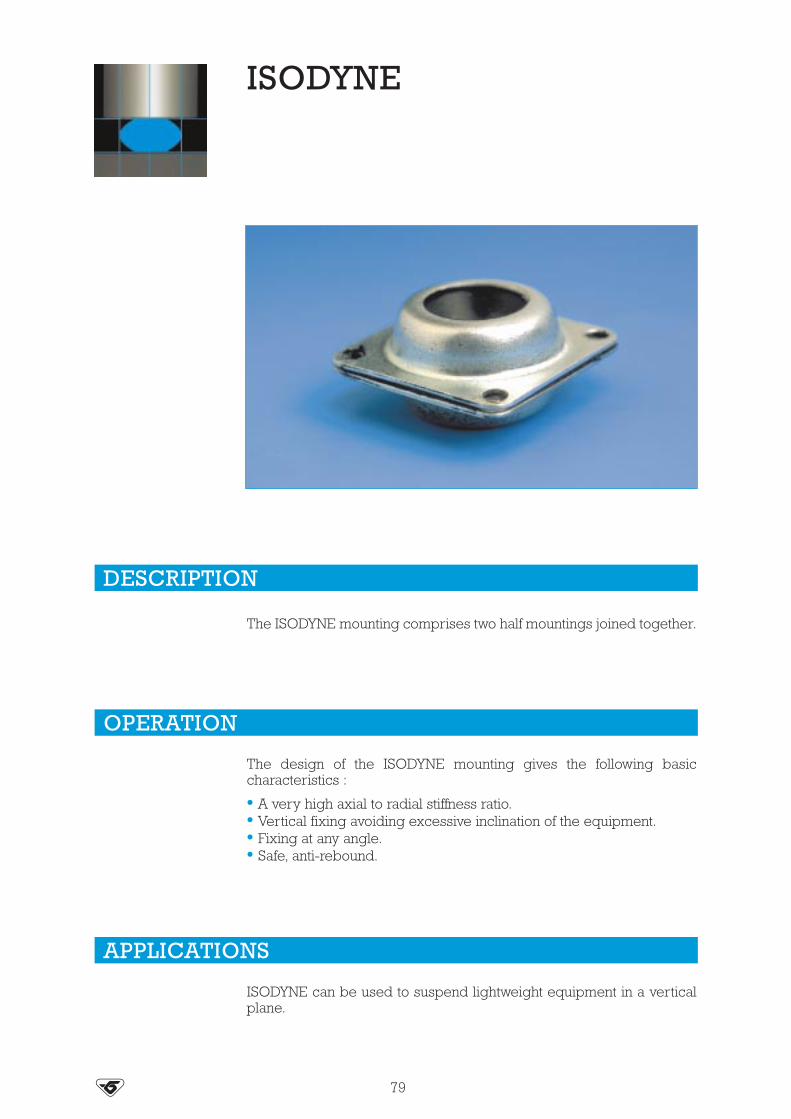
ISODYNE
The ISODYNE mounting comprises two half mountings joined together.
The design of the ISODYNE mounting gives the following basiccharacteristics :
• A very high axial to radial stiffness ratio.• Vertical fixing avoiding excessive inclination of the equipment.• Fixing at any angle.• Safe, anti-rebound.
ISODYNE can be used to suspend lightweight equipment in a verticalplane.
DESCRIPTION
OPERATION
APPLICATIONS
79

Ø C
Ø E
X’
X
D F
D
F
B
J
Fixing clearances (approximate)
Fixing to wallVertical wall
Suspended equipment
Suspended equipment
frame
mounting
Fixing to frame
H
G
80
DIMENSIONS
OPERATING CHARACTERISTICS
See current price list for availability of items.
ASSEMBLY
GmmReference H
mm
284047
551321551441551571
182022
Reference Hardness
504545.60
Bmm
Ø Cmm
551321551441551571
161820
4.26.58.2
Dmm25.43545.5
Ø Emm3.54.26.2
Fmm3244.557.5
Jmm1.622
Weightg102450
Nominal staticloaddaN
Deflect.mm Reference Hard.
2.510
13
551321551441
5045
Nominal staticloaddaN
Deflect.mm Reference Hard.
2535
2.52.5
551571551571
4560
Fixing a control panel against a wall orvertical frame.
Section XX’Load

S.L.F.MOUNTS
SILICONE RUBBER / SPECIAL ELECTRONICS
Natural frequency :10 to 25 Hz
Low frequency high deflection antivibration mounting available in a choice of elastomersincluding high damped silicone. The zinc plated mild steel metalwork is fully bonded forimproved fatigue strength.
These mounts have been designed to protect low mass components and instruments fromvibration and shock and to isolate small rotating machines e.g. pumps and electric motors.
Maximum sinusoidal input at resonance : ± 0.5 mm.Resonance frequencies at maximum input : 10 to 25 Hz dependent on axis and load.Axial to radial stiffness : 3 : 1.Amplification at resonance : silicone mounting : 4 rubber mounting : 10.Maximum displacement during shock : axial : 5 mm.
radial : 7 mm.Mechanical strength corresponding to a continuous acceleration of 10 g at maximum load.
DESCRIPTION
APPLICATIONS
DIMENSIONS
SMALL LOADS / HIGH DEFLECTIONS
OPERATING CHARACTERISTICS
81
Improved stability can be achieved if the mounts are inclined at 45° towards the centre ofgravity.
ASSEMBLY
Roll
M 4 x 0.7
Max depth of thd from face : 5.0 Compression Weight : 6 g approx.
Ø 1
4.0
8.75
17,5 8,5
12.5
M 4
x 0
.7th
d
10
Shear
555507
NB : The * define the type of fixing : combination fixing : 555507 male/male fixing : 555505 female/female fixing : 555506
Partnumber
- 40 to + 70°C
- 54 to + 150°C
0.10 - 0.400.40 - 0.80
0.10 - 0.150.15 - 0.30
0.10 - 0.500.50 - 1.00
0.10 - 0.250.25 - 0.50
0.10 - 1.501.50 - 3.00
0.10 - 0.500.60 - 0.80
Temperature forcontinuous operation
Static loadin shear
kg
Static loadin roll
kg
Static loadin compression
kg
55500*4255500*72
55500*0155500*02
Mix
Silicone 42 ShSilicone 70 Sh
NR 50 ShNR 70 SH
New !

“SANDWICH”MOUNTING
The SANDWICH mounting comprises one or more layers of elastomerbonded to flat, parallel metallic plates. These mountings may becylindrical or rectangular. They are designed to withstand very highcompressive loads. The range of mechanical characteristics is gover-ned by the hardness of the rubber and the number of intermediatemetallic plates.
These mountings can support compression from 20 to 100 bars.
The metal plates usually receive a phosphate anti-corrosion treatment.
The elastomer is polychloroprene which provides a high resistance toatmospheric exposure.
The design of the SANDWICH mounting gives the following basiccharacteristics :
• Very slim.• Large surface area.• Stackable mountings.• The suspended equipment is free to move in all directions.• High ratio of axial stiffness to radial stiffness.• Very high axial loads.
(1) Natural frequencies with max/min loads, see : OPERATING CHARACTERISTICS.
DESCRIPTION
OPERATION
(1) Natural frequency :5 to 13 Hz
82

E
LL
B
H
HA
A
M
B
h
Ø C
D
==
83
MOUNTINGS WITH FIXING PLATES Fig. A
MOUNTINGS WITHOUT FIXING PLATES Fig. B
See current price list for availability of items.
Nominalstatic load
1000-4000
1250-5000
2500-10000
6250-25000
3750-15000
Deflectionmm
12
7
6
3.5
5
Reference
539821
539608
539607
539267
539607
Hard.
50
60
45
70
60
Nominalstatic load
5000-20000
7500-30000
11250-45000
15000-60000
Deflectionmm
6
7
5
4
Reference
539612
539612
539613
539933
Hard.
45
60
60
60
Reference withoutintermediate plate
539608
539612
539613
539821
Reference withintermediate plate
539607
539933
539267
Amm
182
372
702
160
283
Bmm
142
252
252
110
140
Dmm
255
460
805
230
380
Emm
170
300
300
110
140
Hmm
49
61
61
58
76
hmm
Lmm
40
50
50
44
60
58
100
95
35
50
Mmm
235
430
765
202
340
Weightkg
5
18
35
5
9.5
N° holesx Ø C (mm)
6 x 9
6 x 13
6 x 17
4 x 15
6 x 18
Reference
539832539823539833539992539820539835539537539890539939539520539924539903539701519821519822519823
A (=D)mm
200220240250400405500510600650702800750200260280
B (=E)mm
165220200250300255500410500650252250750190230180
Hmm
38270
38140
786166.582
125152
52190300
606060
Maximum static loaddaN
95 000150 000145 000200 000380 000310 000870 000700 000
1 000 0001 500 000
450 000480 000
2 000 000115 000185 000143 000
Fig. BFig. A

H
Ø A
Ø C
B
A H
h
84
CYLINDRICAL MOUNTINGS
DOMINANTLY RADIAL MOUNTINGS
Various types of fixing are available. Consult us for information.
Reference
539904544051539796539983539539539938539937539900544078544079544080
Amm115150200200275320350400600600860
Hmm
Nominal static loaddaN
54110
96.590
27519
105117167285300
1 50012 00018 000
5 0005 000
100 000110 000150 000300 000433 000650 000
Amm
* Multilayer laminated part. Various types of fixing are available. Consult us for information.
Reference
534646
534647
534455
534456
539898*
539917*
539940
539806
544051*
hmm
Bmm
Hmm
Ø Cmm
12,5
12,5
16,5
16,5
13
13
18
18
17
70
70
86
86
100
76
350
120
110
120
120
190
190
146
146
430 x 219
330 x 170
190 x 110
62
62
74
74
88
66
318
100
100
150
150
232
232
180
180
300 x 480
360 x 200
240 x 160
Shear
mm
20
20
25
25
10
10
70
30
50
daN
200
150
500
625
400
250
4500
1200
1800
1 500
1 000
2 000
3 500
3 000
1 500
13 000
3 000
10 000
CompressiondaN

ELIGO
85
See current price list for availability of items.
Reference
537070
537007
537001
537000
537137
537115
537117
537119
537120
537144
537116
537114
148
175
200
87
157
250
340
149
284
400
380
450
Ø Amm
Ø Bmm
Dmm
Hunloaded
mm
Nominalstatic load
daN
Deflectionmm
70
70
70
92
140
155
155
212
212
260
283
283
28
28
28
61
74
80
80
118
118
119
148
148
41
61
62
20
30
62
91
40
78
143
150
180
300
300
180
350
1500
1000
1000
2500
2500
6650
5500
6000
4
4
4
7
14
10
10
12
12
18
20
20
H
D
Ø A
Ø B

SUPPORTSANDBUMP STOPS
86
See current price list for availability of items.
Reference : 514202 - Hardness : 75 - Compressiveload : 5000 daN - Deflection : 8 mm
Reference : 534501 - Hardness : 60 - Load :Compression : 2500 daN - Deflection : 15 mm -Shear load : 300 daN - Deflection : 10 mm
Reference : 817505 - Hardness 60 - Compressiveload : 1500 daN - Deflection : 5 mm
Reference : 813501 - Hardness : 60 - Compressiveload : 1000 daN - Deflection : 4 mm
Reference : 813504 - Hardness 60 - Compressive load :3000 daN - Deflection : 9 mm
Reference : 817605 - Hardness 60 - Compressiveload : 2000 daN - Deflection : 1.4 mm
Reference : 813506 - Hardness 60 - Compressiveload : 4000 daN - Deflection : 2.4 mm

87
See current price list for availability of items.
Deflection : 14 mmMaximum load : 150 daNReference 512389
Deflection : 35 mmMaximum load : 3 000 daNReference 519186
Deflection : 45 mmMaximum load : 4 800 daNReference 512991
M 8M 12
170
200
Ø 14.5
120
160
200
220
160
190
70
3817
47 9436
102
60
10

88
Reference Fig. Amm
Bmm
Cmm
Dmm
Emm
Hmm
Deflectionunder load
mm
LoadmaxiKN
Ø d
E1V-3245-04*E1V-3568-01*E1V-3892-01*E1V-3914-01*E1V-3921-01*E1V-3922-01*E1V-3927-01*E1V-3931-01*E1V-3932-01*E1V-3940-01*E1V-4031-01*E1V-4059-11*
519805519830
43211212111112
135126196170170180170110170170170234170100
125
140110110180110110110
88110125110110
10680
174140140148140
92140140140200140
80
85
118
148
92
90
53533633333533
11036854050564090302065705062
--104025313225--
15.51041403125
50592520286028.52650302551.22812.5
M105/16 or M8
13151515159
151515141511
See Paulstraelastomer range:
Stops
*Vibrachoc range
KN
mm
Distortionunder load
Advantages:- sliding plate.
- integrated stop.- progressive stiffness.
curve exampleLoadmaxi
Fig. 4Fig. 3Fig. 2Fig. 1

OTHERMOUNTINGS
89
See current price list for availability of items. 1 kg � 1 daN
Reference 539515
Ø 9
6
22
4
Ø 15
Ø 36
Ø 27
Compression
Compression:
Deflection: 1.8 mmMaximum load: 3 daN
Reference 544172-11
SMALL LOADS VERSATILE MOUNTING
New !
Ø 96
Ø 54
Ø 285
Ø 420 approx.
1015
205

ReferenceA
mmB
mmH
mmØ C Ø C1
Gmm
G1mm
Lmm
Numberintermed.
plates
538076
539214
539377*
100
100
100
70
70
70
46
46
46
M10
M10
M10
M12
M12
M12
34
31
33
23
23
23
50
50
50
-
2
1
DIMENSIONS
OPERATING CHARACTERISTICS
Reference Hardness Static loaddaN
Deflectionmm
538076
539214
539377
45
40
60
300
300
300
5
1
0.7
90
* This reference has 4 screws.
A
G1B
Ø C
Ø C
H G
Ø C
1
L
* This reference has 4 screws.

DIMENSIONS
OPERATING CHARACTERISTICS
Reference
Reference HardnessAxial stiffness
Load daN
150
230
200
Deflection mm
2
2
4.5
539004
539743
50
60
45
Amm
Bmm
Ø Cmm
Ø C1mm
Dmm
Emm
Hmm
Jmm
Lmm
Mmm
539004539743
5474
4071
15.816.25
25.4 102105
7692
13.533.5
33
82.582.5
-69.5
91
Reference 539004
L
D
E
Ø C1
Ø A
J
H
B
Ø C
Reference 539743
Ø A
Ø C
H
BDL
J
E
M
1 kg � 1 daN

92
ReferenceA
mmC
mmLoaddaN
Fig.
544099
539586
539873
544059
538040
539437
180
190
190
190
280
350
172
170
172
175
252
275
2500
2800
3000
3000
4000
6000
1
1
1
1
3
2
Fig. 1 Fig. 2 Fig. 3
CCC
A AA

Ø 290
M 24
Ø 114
100
Ø 21
Ø 260
Ø 310
93
Reference 539925
Reference 539972Also exists with anti-rebound stop - Reference 539971
770
267
840
900
980

Vertical stiffnessdaN/mm
AE
D
A
P
α
C
A
B
F
C
A
B
B
E12
0°D
B
94
Section AA’ Section BB’
Fig. 2Fig. 1
CHEVRON MOUNTINGS
Reference
544066
539555
539376
538000
539549
539952
246
250
191.5
191
152
179
213
184.5
178
141
160
179
52
60
30
95
79
70
154
197
193
113
130
140
203
240
123
203
300
197
7000
8000
6000
3400
4500
5500
22
5
22
16
26
26
1
1
1
1
2
2
200
120
166
68
80
75
Amm
Bmm
Cmm
Dmm
Emm
LoaddaN
αmm Fig.
-
-
-
-
231
197
Fmm
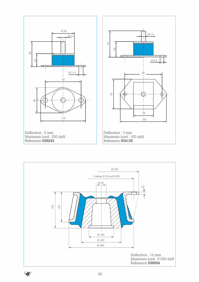
Ø 300
4 holes Ø 22 on Ø 260
Ø 40
Ø 100
Ø 260
Ø 160
10
120
145
Ø 58
M 12
Ø 11.5
92
34
65
115
90M 10
Ø 8.5
86
36
61
106
4570
95
Deflection : 3 mmMaximum load : 150 daNReference 534135
Deflection : 5 mmMaximum load : 250 daNReference 539243
Deflection : 12 mmMaximum load : 6 000 daNReference 539024

96
Compression :
Deflection : 4.5 mmMaximum load : 800 daN
Shear :
Deflection : 6.5 mmMaximum load : 80 daN
Reference 534079
77
5
46
90
78
100
122
Ø 10.5
M 10
Reference E4330-F11
20
Ø 3.2
6.5
Ø 3
1.6
3
VERY LOW LOADS MOUNTING (hard disk, etc.)
New !

LONG TRAVEL
AIR SPRING
The PAULSTRA air spring is a rubber-coated flexible structure seatedand sealed with internal and external steel supports.
The air spring is designed to have the following basic properties :
• Low natural frequency.• Lateral stiffness.• Adjustable height.• Withstands adverse weather conditions and temperatures from - 40°C
to + 70°C.
(1) Natural frequency with max. load, see chapter : OPERATING CHARACTERISTICS.
DESCRIPTION
OPERATION
(1) Natural frequency :1 Hz
97

The air spring must be mounted on an upper plate using a flange thesame shape as the air spring to provide a good seal. The lower part ofthe membrane may rest on a rigid support with a restraining andsealing bead.
PAULSTRA also offers a flexible mounting for the air spring to enablethe suspension to be used in non-standard applications or undertorsion.
Ask us for details of the mounting dimensions.
OPERATING CHARACTERISTICS
ASSEMBLY
98
Reference
545023
H int.mm
120
H ext.mm
250
Ø max. at6 bars (mm)
800
Maximumstatic load
Kn
160
Naturalfrequency*
Hz
1
Stiffness at120 kN/m
62
* Without additional chamber.
Ø max.
H ext.

6 holes Ø 45
8 holes Ø 42
Ø 1050
Ø 120010
0035
810250 x 3
1000
35
1360
1220
35
HEAVY DUTYFENDERS
99
Trapezoidal shock fender Reference 519786
Compression fender Reference 539634
Energy (Joules)
Force (tonnes)
Deflection (m)
Max Force (tonnes)
280 000
83
0.45
166
Energy (Joules)
Force (tonnes)Deflection (m)
200 000
60
0.4

134
Ø 6
3
Ø 32
10
200 250 500 250500
40
2000
250
Ø B
Ø A
C
100
Reference
811203811189
Max radial load(tonne)
4090
Max axial load(tonne)
70150
Weight (kg)
70115
Reference
811203811189
A (mm)
482.4533
B (mm)
787.4864
C (mm)
228.6300
Dimensions
Energy (Joules)
Force (tonnes)
Deflection (m)
14 000
15
0.1
Intermediate lengths on request Characteristics for a length of 1 m
Force is dependent on fixing.Consult us for information.
Protection ring
Trapezoidal shock fender Reference 519794

6 holes Ø 45
720
600
960
200
200
200
180
A-A
A A
4545
H
820
150
F
Section A
Ø 14 A
225 400 400 400 400 400
2450
210
250
9015
101
Energy (Joules)
Force in shear (tonnes)
Deflection in shear (m)
Compression static load (tonnes)
Compression static deflection (mm)
36
0.62
40
30
1 100 000
Weight # 755 kgHeight (mm) = 700 ± 5
Rectangular buffer Reference 519782
Shock fender to shear Reference 539652
Energy (Joules)
Force (tonnes)
8 000
150
Weight # 90 kg
Intermediate lengths on request.

STRASONIC®
102
STRASONIC is a range of complex materials designed to provide thebest acoustic isolation. Their structure is based on polyurethane foamsor cellular rubber.
Their main function is to reduce airbone noise (Isolation, Absorptionand Damping) in partial or complete enclosures of machinery.
The STRASONIC material can be used in a range of applications suchas : air conditioning, pumps, presses, compressors, electric motorsdiesel engines, generator sets, gearboxes, turbines, agricultural orconstruction equipment and other machinery.
Due to their design (Sheets of 500 mm x 500 mm or 500 mm x 700 mm)they are easy to handle, light and a self adhesive side simplifies theinstallation (depending of the type of foam).
DESCRIPTION
APPLICATIONS
New !

103
Structure
CHARACTERISTICS OF THE STRASONIC® RANGE
POLYURETHANE FOAMS
Reference Structure Composition and properties Acoustic performances Applications
841000
50 mm of corrugated PU Ether absorp-tion foam. Self adhesive layer on oneside.Temperature range:from - 25°C to + 110°C.Fire resistance: M4/UL94.
Average absorption factor K: 65%Approximate gain on a 2 mm steelsheet: - 10 dB (A).The corrugations increase theabsorption surface by 40%.
- Air conditioning,- Fans,- Ventilation shaft- Pumps- Presses,- Air compressors, ...
841001841001-50
50 mm of heavy weight 5 kg/m2,corrugated PU Ether absorption foambonded to 3 mm of spring foam.Temperature range:from - 25°C to + 110°C.Fire resistance: M4/UL94.
Average absorption factor K: 68%.Approximate gain on a 2 mm steelsheet: - 25 dB (A).Very good performance from500 Hz to 5000 Hz.
- Air compressors,- Gearboxes,- Presses,- Compressors,- Electric motors , ...
841002
100% waterproof black PU filmbonded to 25 mm of heavy weight5 kg/m2 corrugated PU Ether absorptionfoam bonded to 3 mm of spring foam.Temperature range:from - 25°C to + 110°C.Fire resistance: M4/UL94.
Approximate gain on a 2 mm steelsheet: - 20 dB (A).Very good performance from125 Hz to 4000 Hz.
- Generator sets,- Agricultural and Construc-
tion, equipment machines,- Electric and Diesel engines,- Compressors, Pumps,- Turbines- Test benches, ...
Format: sheets of 500 mm x 700 mm.
Please consult us for availability of the adhesive (non stocked item).
CELLULAR RUBBER
Packaging
Can 5 litresCan 1 litre
To adhere the sheets (part number 841001 and 841002) we recommend the STRAGLUE®
Ref. Color
Soft brownSoft brown
Density
0.89 g/ml0.89 g/ml
Drying time
1 to 3 minutes1 to 3 minutes
Temperatureresistance
� 80°C� 80°C
Solver
HydrocarbonHydrocarbon
Advisedquantity
120 g/m2/face120g/m2/face
841010841011
Reference Composition and properties Acoustics performances Applications
841003
NBR based waterproof cellular rubber,thickness 33 mm. Self adhesive layeron one side.Temperature range static from - 40°C to+ 105°C continuous.Very good resistance to oil, ozone, airand UV.Fire resistance: M4/FMVSS 302.
Average absorption factor K ≥ 30%from 500 Hz.Very good acoustic performance inhigh frequencies above 2500 Hz.Approximate gain on a 2 mm steelsheet: - 10 dB (A) at 2500 Hz /- 20 dB (A) at 5000 Hz.
- Sand blasting systems, Saws,- High speed drills,- Vacuum pumps,- Injection presses,- Gearboxes...
841004
EPDM based cellular rubber with halfclosed cells. Thickness 15 mm. Selfadhesive layer on one side.Temperature range continuous from - 40°C to + 130°C.Very good resistance to air, ozone andUV. Very flexible. Good ageing resis-tance. Waterproof if slightly compressed.Fire resistance: FMVSS 302.
Average absorption factor K ≥ 30%from 600 Hz.Very good acoustic performance in high frequencies above 2000 Hz.Approximate gain on a 2 mm steelsheet: - 8 dB (A) at 2500 Hz / - 20 dB(A) at 5000 Hz.
- Air Jet positioning,- Sand blasting systems, Saws,- High speed drills,- Vacuum pumps,- Injection presses,- Gearboxes...
841005
EPDM based cellular rubber half closedcells. Thickness 22.5 mm. Self adhesivelayer on one side.Temperature range continuous from - 40°C to + 130°C.Very good resistance to air, ozone andUV. Very flexible. Good ageing resis-tance. Waterproof if slightly compressed.Fire resistance: FMVSS 302.
Average absorption factor K ≥ 30%from 500 Hz.Very good acoustic performance in high frequencies above 2000 Hz.Approximate gain on a 2 mm steelsheet: - 10 dB (A) at 2500 Hz / - 27 dB (A) at 5000 Hz.
- Air Jet positioning,- Sand blasting systems, Saws,- High speed drills,- Vacuum pumps,- Injection presses,- Gearboxes...
Format: sheets of 500 mm x 500 mm.
Reference 841001-50: Self adhesive layer on one side version.

104
ALPHABETIC INDEX - PAULSTRA RANGE
BatraBatraBatraBatraBatraBatraBatraBatraBatraBatraBatraBatraBatra
BecaBecaBecaBecaBecaBecaBecaBecaBecaBecaBecaBecaBeca
Bogie mounting
Chevron mounting
Mounting
Chevron mountingChevron mountingChevron mountingChevron mounting
Conical bump stopConical Bump stopConical bump stopConical bump stopConical bump stopConical bump stopConical bump stopConical bump stopConical bump stopConical bump stopConical bump stopConical bump stopConical bump stopConical bump stop
Cylindrical SandwichCylindrical SandwichCylindrical SandwichCylindrical SandwichCylindrical SandwichCylindrical SandwichCylindrical SandwichCylindrical SandwichCylindrical Sandwich
Diabolo bump stopDiabolo bump stopDiabolo bump stopDiabolo bump stopDiabolo bump stopDiabolo stud
541050541082541083541100541112541144541145541146541174541175541185541249541250
533108533109533151533152533202533203533581533609533623533641533652533661533681
539549
539952
514202
538000539376539555544066
512215512251521301512307512501512502512503512516512517512601512608512700512721512951
539796539900539904539937539938539983544078544079544080
511571511572511601511801511951521201
71717171717171717171717171
73737373737373737373737373
94
94
86
94949494
6161616161616161616161616161
848484848484848484
616161616137
Diabolo studDiabolo studDiabolo studDiabolo studDiabolo studDiabolo studDiabolo studDiabolo stud
EligoEligoEligoEligoEligoEligoEligoEligoEligoEligoEligoEligo
Engine mountingsEngine mountingsEngine mountingsEngine mountings
Triaxdyn
EvidgomEvidgomEvidgomEvidgomEvidgomEvidgomEvidgomEvidgomEvidgomEvidgomEvidgomEvidgomEvidgomEvidgomEvidgomEvidgomEvidgomEvidgomEvidgomEvidgomEvidgomEvidgomEvidgomEvidgomEvidgomEvidgomEvidgomEvidgomEvidgomEvidgomEvidgomEvidgomEvidgomEvidgomEvidgomEvidgomEvidgomEvidgomEvidgomEvidgomEvidgom
521300521403521571521572521602521801521802521951
537000537001537007537070537114537115537116537117537119537120537137537144
905201905202905203905206
905233
810002810003810004810005810006810008810009810012810013810014810015810016810019810020810022810023810025810029810035810046810642810644810645810653810655810666810669810731810732810733810734810735810736810766810768810769810770810773810775810776810779
3737373737373737
858585858585858584858585
50505050
48
5656625656565656565656565656626262626262626262626262626262
56-576262
56-5756-5756-5756-5756-5756-5756-5756-5756-57
EvidgomEvidgom
IsodyneIsodyneIsodyne
IsoflexIsoflexIsoflex
Heavy duty fenderHeavy duty fender
LevaflexLevaflexLevaflexLevaflexLevaflex
Locomotive mountingLocomotive mountingLocomotive mountingLocomotive mountingLocomotive mountingLocomotive mounting
MinifixMinifixMinifixMinifixMinifix
Mounting
MountingMountingMountingMountingMountingMountingMounting
MountingMountingMountingMountingMountingMountingMountingMountingMountingMountingMountingMountingMountingMountingMounting
NivofixNivofixNivofixNivofixNivofixNivofixNivofixNivofix
PaulstradynPaulstradyn
810780810784
551321551441551571
552231552241552428
539652539634
514085514110514130514160514200
538040539437539586539873544059544099
530801530802530805530806530807
E4330-F11
534501813501813504813505813506817505817605
530170534079534135538076539004539743539515539214539024539377539243539925539971539972
544172-11
530810530815530820530825530830530835530840530850
533701533702
56-5756-57
808080
787878
10099
6262626262
929292929292
6767676767
96
86868686868686
899695909191969095909593939389
6666666666666666
39-4139-41
Designation Reference Page Designation Reference Page Designation Reference Page

105
PaulstradynPaulstradynPaulstradynPaulstradynPaulstradynPaulstradynPaulstradynPaulstradynPaulstradynPaulstradynPaulstradynPaulstradynPaulstradynPaulstradynPaulstradynPaulstradyn
Pneumatic mounting
PolyflexPolyflexPolyflexPolyflexPolyflex
Protection ringProtection ring
Radiaflex bump stopRadiaflex bump stopRadiaflex bump stopRadiaflex bump stopRadiaflex bump stopRadiaflex bump stopRadiaflex bump stopRadiaflex bump stopRadiaflex bump stopRadiaflex bump stopRadiaflex bump stopRadiaflex bump stopRadiaflex bump stopRadiaflex bump stopRadiaflex bump stopRadiaflex bump stopRadiaflex bump stopRadiaflex bump stopRadiaflex bump stopRadiaflex bump stopRadiaflex bump stopRadiaflex bump stopRadiaflex bump stopRadiaflex bump stopRadiaflex bump stopRadiaflex bump stopRadiaflex bump stopRadiaflex bump stopRadiaflex bump stopRadiaflex bump stopRadiaflex bump stopRadiaflex bump stopRadiaflex bump stopRadiaflex bump stopRadiaflex bump stopRadiaflex bump stopRadiaflex bump stopRadiaflex bump stopRadiaflex bump stopRadiaflex bump stopRadiaflex bump stopRadiaflex bump stopRadiaflex bump stopRadiaflex bump stopRadiaflex bump stop
533703533704533705533706533707533708533709533710533711533712533713533714533715533716533717533719
545023
532300532500532561532563532750
811189811203
E3RP0953E3RP0956
511110511115511125511128511150511151511152511153511154511155511156511157511158511159511160511161511162511163511164511200511215511220511225511230511251511265511270511275511280511285511290511292511294511296511298511308511310511312511314511401511450511452511454
39-4139-4139-4139-4139-4139-4139-4139-4139-4139-4139-4139-4139-4139-4139-4139-41
98
7575757575
100100
3535
35-6135-6135-6135-6135-6135-6136-6136-6136-6135-6136-6135-6135-6135-6135-6135-6136-6136-6136-6135-6135-6135-6135-6135-6135-6135-6135-6135-6135-6135-6135-6135-6135-6135-6135-6135-6135-6135-6135-6135-6135-6135-6135-61
Radiaflex bump stopRadiaflex bump stopRadiaflex bump stopRadiaflex bump stopRadiaflex bump stopRadiaflex bump stopRadiaflex bump stopRadiaflex bump stopRadiaflex bump stopRadiaflex bump stopRadiaflex bump stopRadiaflex bump stopRadiaflex bump stopRadiaflex bump stopRadiaflex bump stopRadiaflex bump stop
Radiaflex studRadiaflex studRadiaflex studRadiaflex studRadiaflex studRadiaflex studRadiaflex studRadiaflex studRadiaflex studRadiaflex studRadiaflex studRadiaflex studRadiaflex studRadiaflex studRadiaflex studRadiaflex studRadiaflex studRadiaflex studRadiaflex studRadiaflex studRadiaflex studRadiaflex studRadiaflex studRadiaflex studRadiaflex studRadiaflex studRadiaflex studRadiaflex studRadiaflex studRadiaflex studRadiaflex studRadiaflex studRadiaflex studRadiaflex studRadiaflex studRadiaflex studRadiaflex studRadiaflex studRadiaflex studRadiaflex studRadiaflex studRadiaflex studRadiaflex studRadiaflex studRadiaflex studRadiaflex studRadiaflex studRadiaflex studRadiaflex studRadiaflex studRadiaflex studRadiaflex studRadiaflex studRadiaflex studRadiaflex studRadiaflex studRadiaflex studRadiaflex studRadiaflex stud
511456511525511535511545511625511635511645511735511750511770511830511840511870511880513601513801
520010520011520012520013520015520016520017520018520021520022520023520024520025520026520027520028520029520030520031520032520033520035520036520038520039520040520041520042520044520045520046520052520053520054520055520056520057520058520059520089520100520101520102520103520500520501520502520503520505520506520507520508520511520512520513520514520516520517520518
35-6135-6135-6135-6135-6135-6135-6135-6135-6135-6135-6135-6135-6135-61
3535-61
3636363636363636363636363636363636363636363636363636363636363636363636363636363636363636363636363636363636363636363636
Radiaflex studRadiaflex studRadiaflex studRadiaflex studRadiaflex studRadiaflex studRadiaflex studRadiaflex studRadiaflex studRadiaflex studRadiaflex studRadiaflex studRadiaflex studRadiaflex studRadiaflex studRadiaflex studRadiaflex studRadiaflex studRadiaflex studRadiaflex studRadiaflex studRadiaflex studRadiaflex studRadiaflex studRadiaflex studRadiaflex studRadiaflex studRadiaflex studRadiaflex studRadiaflex studRadiaflex studRadiaflex studRadiaflex studRadiaflex studRadiaflex studRadiaflex studRadiaflex studRadiaflex studRadiaflex studRadiaflex studRadiaflex studRadiaflex studRadiaflex studRadiaflex studRadiaflex studRadiaflex studRadiaflex studRadiaflex studRadiaflex studRadiaflex studRadiaflex studRadiaflex studRadiaflex studRadiaflex studRadiaflex studRadiaflex studRadiaflex studRadiaflex studRadiaflex studRadiaflex studRadiaflex studRadiaflex studRadiaflex studRadiaflex studRadiaflex studRadiaflex studRadiaflex studRadiaflex studRadiaflex studRadiaflex studRadiaflex studRadiaflex studRadiaflex studRadiaflex studRadiaflex studRadiaflex studRadiaflex stud
520520520521520522520523520525520526520528520529520530520531520532520534520535520536520541520542520543520545520546520547520550520551520552520553520554520555520556521128521161521178521181521249521251521292521293521294521295521296521297521298521299521308521310521312521314521319521340521341521342521343521344521401521450521452521454521456521580521581521582521601521603521641521650521651521653521653521655521656521657521658521705521710521711521803521840521841521842
3636363636363636363636363636363636363635363636363636363535353535353535353535353535353535353535353535353535353535353535353535353535353535353535353535353535
Designation Reference Page Designation Reference Page Designation Reference Page

106
Radiaflex studRadiaflex studRadiaflex studRadiaflex stud
Rectangular buffer
SandwichSandwichSandwichSandwichSandwichSandwichSandwichSandwichSandwichSandwichSandwichSandwichSandwichSandwichSandwichSandwichSandwichSandwichSandwichSandwichSandwichSandwichSandwichSandwichSandwichSandwichSandwichSandwichSandwichSandwichSandwich
521843521908521909521910
519782
519821519822519823534455534456534646534647539267539520539537539607539608539612539613539701539820539821539823539832539833539835539890539898539903539917539924539933539939539940539992544051
35353535
101
83838384848484838383838383838383838383838383848384838383848384
S.C. mountingS.C. mountingS.C. mountingS.C. mountingS.C. mountingS.C. mountingS.C. mountingS.C. mountingS.C. mountingS.C. mountingS.C. mountingS.C. mountingS.C. mountingS.C. mountingS.C. mountingS.C. mountingS.C. mountingS.C. mountingS.C. mountingS.C. mounting
S.C.P. mountingS.C.P. mountingS.C.P. mounting
S.L.F.S.L.F.S.L.F.
Special bump stopSpecial bump stopSpecial bump stopSpecial bump stopSpecial bump stop
StabifixStabifixStabifix
531201531216531240531259531261531301531327531401531402531611531701531702531714531931531932531933531939531940531941531947
530120530220530420
555005555006555007
512389512991519186519805519830
530170530175530181
52-5352-5352-5352-5352-5352-5352-5352-5352-5352-5352-5352-5352-5352-5352-5352-5352-5352-5352-5352-53
767676
818181
8787878888
464646
StabifixStabifix
StabiflexStabiflexStabiflexStabiflexStabiflex
S.T.C.S.T.C.S.T.C.S.T.C.S.T.C.S.T.C.
StrasonicStrasonicStrasonicStrasonicStrasonicStrasonicStrasonic
StraglueStraglue
Trapezoidal fenderTrapezoidal fender
TraxiflexTraxiflexTraxiflexTraxiflexTraxiflexTraxiflexTraxiflex
Triaxdyn
530184530185
530603530613530622530642530652
539190539191539886539887539920539951
841000841001
841001-50841002841003841004841005
841010841011
519786519794
535600535603
53560631535611535612535621535622
905233
4646
4343434343
595959595959
103103103103103103103
103103
99100
69696969696767
46
Designation Reference Page Designation Reference Page Designation Reference Page
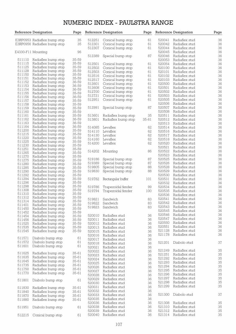
NUMERIC INDEX - PAULSTRA RANGEReference Designation Page Reference Designation Page Reference Designation Page
E3RP0953E3RP0956
E4330-F11
511110511115511125511128511150511151511152511153511154511155511156511157511158511159511160511161511162511163511164511200511215511220511225511230511251511265511270511275511280511285511290511292511294511296511298511308511310511312511314511401511450511452511454511456511525511535511545
511571511572511601
511625511635511645511735511750511770
511801
511830511840511870511880
511951
512215
Radiaflex bump stopRadiaflex bump stop
Mounting
Radiaflex bump stopRadiaflex bump stopRadiaflex bump stopRadiaflex bump stopRadiaflex bump stopRadiaflex bump stopRadiaflex bump stopRadiaflex bump stopRadiaflex bump stopRadiaflex bump stopRadiaflex bump stopRadiaflex bump stopRadiaflex bump stopRadiaflex bump stopRadiaflex bump stopRadiaflex bump stopRadiaflex bump stopRadiaflex bump stopRadiaflex bump stopRadiaflex bump stopRadiaflex bump stopRadiaflex bump stopRadiaflex bump stopRadiaflex bump stopRadiaflex bump stopRadiaflex bump stopRadiaflex bump stopRadiaflex bump stopRadiaflex bump stopRadiaflex bump stopRadiaflex bump stopRadiaflex bump stopRadiaflex bump stopRadiaflex bump stopRadiaflex bump stopRadiaflex bump stopRadiaflex bump stopRadiaflex bump stopRadiaflex bump stopRadiaflex bump stopRadiaflex bump stopRadiaflex bump stopRadiaflex bump stopRadiaflex bump stopRadiaflex bump stopRadiaflex bump stopRadiaflex bump stop
Diabolo bump stopDiabolo bump stopDiabolo bump stop
Radiaflex bump stopRadiaflex bump stopRadiaflex bump stopRadiaflex bump stopRadiaflex bump stopRadiaflex bump stop
Diabolo bump stop
Radiaflex bump stopRadiaflex bump stopRadiaflex bump stopRadiaflex bump stop
Diabolo bump stop
Conical bump stop
3535
96
35-5935-5935-5935-5935-5935-5936-5936-5936-5935-5936-5935-5935-5935-5935-5935-5936-5936-5936-5935-5935-5935-5935-5935-5935-5935-5935-5935-5935-5935-5935-5935-5935-5935-5935-5935-5935-5935-5935-5935-5935-5935-5935-5935-5935-5935-5935-59
616161
35-6135-6135-6135-6135-6135-61
61
35-6135-6135-6135-61
61
61
512251512301512307
512389
512501512502512503512516512517512601512608512700512721512951
512991
513601513801
514085514110514130514160514200
514202
519186519389519805519830
519782
519786519794
519821519822519823
520010520011520012520013520015520016520017520018520021520022520023520024520025520026520027520028520029520030520031520032520033520035520036520038520039520040
Conical bump stopConical bump stopConical bump stop
Special bump stop
Conical bump stopConical bump stopConical bump stopConical bump stopConical bump stopConical bump stopConical bump stopConical bump stopConical bump stopConical bump stop
Special bump stop
Radiaflex bump stopRadiaflex bump stop
LevaflexLevaflexLevaflexLevaflexLevaflex
Mounting
Special bump stopSpecial bump stopSpecial bump stopSpecial bump stop
Rectangular buffer
Trapezoidal fenderTrapezoidal fender
SandwichSandwichSandwich
Radiaflex studRadiaflex studRadiaflex studRadiaflex studRadiaflex studRadiaflex studRadiaflex studRadiaflex studRadiaflex studRadiaflex studRadiaflex studRadiaflex studRadiaflex studRadiaflex studRadiaflex studRadiaflex studRadiaflex studRadiaflex studRadiaflex studRadiaflex studRadiaflex studRadiaflex studRadiaflex studRadiaflex studRadiaflex studRadiaflex stud
616161
87
61616161616161616161
87
3535-61
6262626262
86
87878888
101
99100
838383
3636363636363636363636363636363636363636363636363636
520041520042520044520045520046520053520054520100520101520102520103520500520501520502520503520505520506520507520508520511520512520513520514520516520517520518520520520521520522520523520525520526520528520529520530520531520532520534520535520536520541520542520543520545520546520547520550520551521128521178
521201
521249521251521292521293521294521295521296521297521298521299
521300
521308521310521312521314
Radiaflex studRadiaflex studRadiaflex studRadiaflex studRadiaflex studRadiaflex studRadiaflex studRadiaflex studRadiaflex studRadiaflex studRadiaflex studRadiaflex studRadiaflex studRadiaflex studRadiaflex studRadiaflex studRadiaflex studRadiaflex studRadiaflex studRadiaflex studRadiaflex studRadiaflex studRadiaflex studRadiaflex studRadiaflex studRadiaflex studRadiaflex studRadiaflex studRadiaflex studRadiaflex studRadiaflex studRadiaflex studRadiaflex studRadiaflex studRadiaflex studRadiaflex studRadiaflex studRadiaflex studRadiaflex studRadiaflex studRadiaflex studRadiaflex studRadiaflex studRadiaflex studRadiaflex studRadiaflex studRadiaflex studRadiaflex studRadiaflex studRadiaflex stud
Diabolo stud
Radiaflex studRadiaflex studRadiaflex studRadiaflex studRadiaflex studRadiaflex studRadiaflex studRadiaflex studRadiaflex studRadiaflex stud
Diabolo stud
Radiaflex studRadiaflex studRadiaflex studRadiaflex stud
3636363636363636363636363636363636363636363636363636363636363636363636363636363636363636363636363636
37
35353535353535353535
37
35353535
107

Reference Designation Page Reference Designation Page Reference Designation Page
521319521340521341521342521343521344521401
521403
521450521452521454521456
521571521572
521580521581521582521601
521602
521603521641521650521651521705521710521711
521801521802
521803521840521841521842521843521908521909521910
521951
530120
530170530175530181530184530185
530220530420
530603530613530622530642530652
530805530806
530810530815530820530825530830530835
Radiaflex studRadiaflex studRadiaflex studRadiaflex studRadiaflex studRadiaflex studRadiaflex stud
Diabolo stud
Radiaflex studRadiaflex studRadiaflex studRadiaflex stud
Diabolo studDiabolo stud
Radiaflex studRadiaflex studRadiaflex studRadiaflex stud
Diabolo stud
Radiaflex studRadiaflex studRadiaflex studRadiaflex studRadiaflex studRadiaflex studRadiaflex stud
Diabolo studDiabolo stud
Radiaflex studRadiaflex studRadiaflex studRadiaflex studRadiaflex studRadiaflex studRadiaflex studRadiaflex stud
Diabolo stud
S.C.P. mounting
StabifixStabifixStabifixStabifixStabifix
S.C.P. mountingS.C.P. mounting
StabiflexStabiflexStabiflexStabiflexStabiflex
MinifixMinifix
NivofixNivofixNivofixNivofixNivofixNivofix
35353535353535
37
35353535
3737
35353535
37
35353535353535
3737
3535353535353535
37
76
4646464646
7676
4343434343
6767
666666666666
530840530850
531201531216531240531259531261531301531327531401531402531611531701531702531714531931531932531933531939531940531941531947
532300532500532561532563532750
533108533109533151533152533202533203533581533609533623533641533652533661533681
533701533702533703533704533705533706533707533708533709533710533711533712533713533714533715533716533717533718533719
534079534135
534455534456
534501
534646
NivofixNivofix
S.C. mountingS.C. mountingS.C. mountingS.C. mountingS.C. mountingS.C. mountingS.C. mountingS.C. mountingS.C. mountingS.C. mountingS.C. mountingS.C. mountingS.C. mountingS.C. mountingS.C. mountingS.C. mountingS.C. mountingS.C. mountingS.C. mountingS.C. mounting
PolyflexPolyflexPolyflexPolyflexPolyflex
BecaBecaBecaBecaBecaBecaBecaBecaBecaBecaBecaBecaBeca
PaulstradynPaulstradynPaulstradynPaulstradynPaulstradynPaulstradynPaulstradynPaulstradynPaulstradynPaulstradynPaulstradynPaulstradynPaulstradynPaulstradynPaulstradynPaulstradynPaulstradynPaulstradynPaulstradyn
MountingMounting
SandwichSandwich
Mounting
Sandwich
6666
52-5352-5352-5352-5352-5352-5352-5352-5352-5352-5352-5352-5352-5352-5352-5352-5352-5352-5352-5352-53
7575757575
73737373737373737373737373
39-4139-4139-4139-4139-4139-4139-4139-4139-4139-4139-4139-4139-4139-4139-4139-4139-4139-4139-41
9695
8484
86
84
534647
535600535603
53560361535611535612535621535622
537000537001537007537070537114537115537116537117537119537120537137537144
538000
538040
538076539004539024
539190539191
539214539243
539267
539376
539377
539437
539515
539520539537
539539
539549539555
539586
539607539608539612539613
539634539652
539701
539743
539796
539806539820539821
Sandwich
TraxiflexTraxiflexTraxiflexTraxiflexTraxiflexTraxiflexTraxiflex
EligoEligoEligoEligoEligoEligoEligoEligoEligoEligoEligoEligo
Chevron mounting
Locomotive mounting
MountingMountingMounting
S.T.C.S.T.C.
MountingMounting
Sandwich
Chevron mounting
Mounting
Locomotive mounting
Mounting
SandwichSandwich
Cylindrical sandwich
Chevron mountingChevron mounting
Locomotive mounting
SandwichSandwichSandwichSandwich
Heavy duty fenderHeavy duty fender
Sandwich
Mounting
Cylindrical sandwich
SandwichSandwichSandwich
84
69696969696969
858585858585858585858585
94
92
909195
5959
9095
83
94
90
92
96
8383
84
9494
92
83838383
99101
83
91
84
848383
108

Reference Designation Page Reference Designation Page Reference Designation Page
539823539832539833539835
539873
539886539887
539890539898
539900
539903
539904
539917
539920
539924
539925
539933539937539938
539939539940
539951
539952
539971539972
539983
539992
541050541082541083541100541112541144
SandwichSandwichSandwichSandwich
Locomotive mounting
S.T.C.S.T.C.
SandwichSandwich
Cylindrical sandwich
Sandwich
Cylindrical sandwich
Sandwich
S.T.C.
Sandwich
Support
SandwichCylindrical sandwichCylindrical sandwich
SandwichSandwich
S.T.C.
Chevron mounting
MountingMounting
Cylindrical sandwich
Sandwich
BatraBatraBatraBatraBatraBatra
83838383
92
5959
8384
84
83
84
84
59
83
83
838484
8384
59
94
9393
84
83
717171717171
541145541146541174541175541185541249541250
544051
544059
544066
544078544079544080
544099
545023544172-11
551321551441551571
552231552241552428
555005555006555007
810002810003810004810005810006810008810009810012810013810014810015810016810019810020810022810023810025
BatraBatraBatraBatraBatraBatraBatra
Sandwich
Locomotive mounting
Chevron mounting
Cylindrical sandwichCylindrical sandwichCylindrical sandwich
Locomotive mounting
Pneumatic mountingMounting
IsodyneIsodyneIsodyne
IsoflexIsoflexIsoflex
S.L.F.S.L.F.S.L.F.
EvidgomEvidgomEvidgomEvidgomEvidgomEvidgomEvidgomEvidgomEvidgomEvidgomEvidgomEvidgomEvidgomEvidgomEvidgomEvidgomEvidgom
71717171717171
84
92
94
848484
92
9989
808080
787878
818181
5656625656565656565656565656626262
810029810035810046810642810644810645810653810655810666810669810731810732810733810734810735810736810766810768810769810770810773810775810776810779810780810784
811189811203
813501813504813506817505817605
841000841001
841001-50841002841003841004841005
841010841011
905201905202905203905206
905233
EvidgomEvidgomEvidgomEvidgomEvidgomEvidgomEvidgomEvidgomEvidgomEvidgomEvidgomEvidgomEvidgomEvidgomEvidgomEvidgomEvidgomEvidgomEvidgomEvidgomEvidgomEvidgomEvidgomEvidgomEvidgomEvidgom
Protection ringProtection ring
MountingMountingMountingMountingMounting
StrasonicStrasonicStrasonicStrasonicStrasonicStrasonicStrasonic
StraglueStraglue
Engine mountingsEngine mountingsEngine mountingsEngine mountings
Triaxdyn
626262626262626262626262
56-576262
56-5756-5756-5756-5756-5756-5756-5756-5756-5756-5756-57
100100
8686868686
103103103103103103103
103103
50505050
48
109

VIBRACHOC ELASTOMERRANGE
111
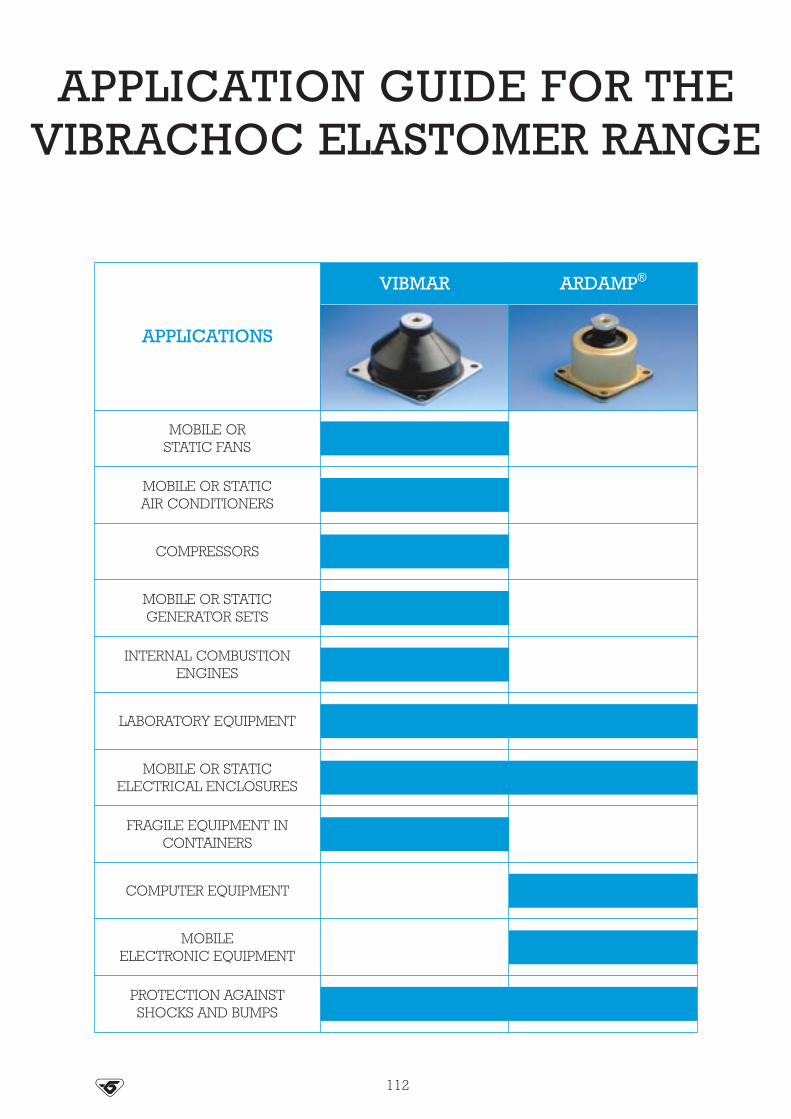
PROTECTION AGAINSTSHOCKS AND BUMPS
112
APPLICATION GUIDE FOR THE VIBRACHOC ELASTOMER RANGE
APPLICATIONS
MOBILE ORSTATIC FANS
MOBILE OR STATICAIR CONDITIONERS
COMPRESSORS
MOBILE OR STATICGENERATOR SETS
INTERNAL COMBUSTIONENGINES
LABORATORY EQUIPMENT
MOBILE OR STATICELECTRICAL ENCLOSURES
FRAGILE EQUIPMENT INCONTAINERS
COMPUTER EQUIPMENT
MOBILEELECTRONIC EQUIPMENT
VIBMAR ARDAMP®

113
APPLICATION GUIDE FOR THE VIBRACHOC ELASTOMER RANGE
APPLICATIONS
MOBILE ORSTATIC FANS
MOBILE OR STATICAIR CONDITIONERS
COMPRESSORS
MOBILE OR STATICGENERATOR SETS
INTERNAL COMBUSTIONENGINES
LABORATORY EQUIPMENT
MOBILE OR STATICELECTRICAL ENCLOSURES
FRAGILE EQUIPMENT INCONTAINERS
COMPUTER EQUIPMENT
SHIPBOARDELECTRONIC EQUIPMENT
PROTECTION AGAINSTSHOCKS AND BUMPS
SPECIALPACKAGING
SPECIALELECTRONICS

VIBMAR
The VIBMAR series has a base plate with two or four mounting holesand a tapped steel core.The elastomer is bonded to the steel.
E1N104 and E1N106 versions have a conical spring embedded in therubber.
Environmental protection is provided by painting the metal parts andby coating the elastomer with an ozone resistant compound.
These multi-axis low frequency dampers have been specially designedto protect electrical or electronic racks and marine or road transportgenerator sets (on board or not). They are cone-shaped to absorbconsiderable displacement and shocks.
DESCRIPTION
APPLICATIONS
114
Natural frequency :5 to 12 Hz
with nominal load
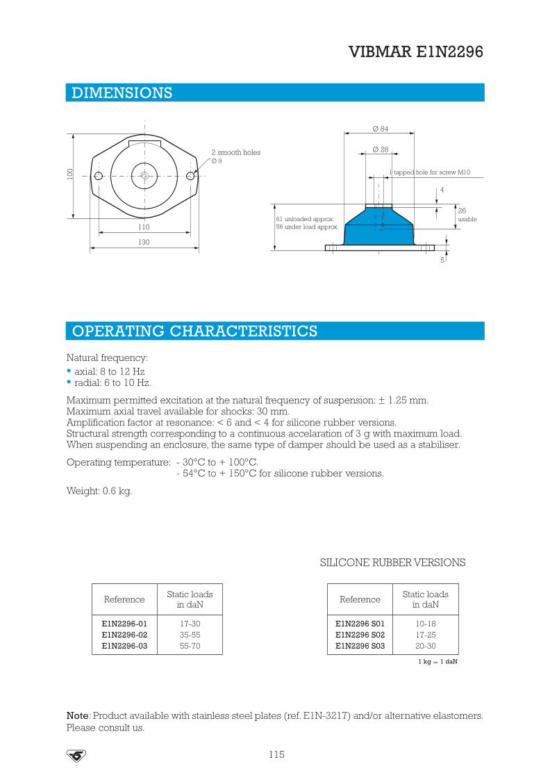
115
DIMENSIONS
VIBMAR E1N2296
OPERATING CHARACTERISTICS
Natural frequency:• axial: 8 to 12 Hz• radial: 6 to 10 Hz.
Maximum permitted excitation at the natural frequency of suspension: ± 1.25 mm.Maximum axial travel available for shocks: 30 mm.Amplification factor at resonance: < 6 and < 4 for silicone rubber versions.Structural strength corresponding to a continuous accelaration of 3 g with maximum load.When suspending an enclosure, the same type of damper should be used as a stabiliser.
Operating temperature: - 30°C to + 100°C.- 54°C to + 150°C for silicone rubber versions.
Weight: 0.6 kg.
Note: Product available with stainless steel plates (ref. E1N-3217) and/or alternative elastomers.Please consult us.
Reference Static loadsin daN
E1N2296-01E1N2296-02E1N2296-03
17-3035-5555-70
Reference Static loadsin daN
E1N2296 S01E1N2296 S02E1N2296 S03
10-1817-2520-30
SILICONE RUBBER VERSIONS
2 smooth holesØ 9
130
110
100
61 unloaded approx.56 under load approx.
5
1 tapped hole for screw M10
4
Ø 28
Ø 84
26usable
1 kg � 1 daN

116
VIBMAR E1N101
OPERATING CHARACTERISTICS
Natural frequency:• axial: 5 to 9 Hz• radial: 4.5 to 9 Hz.
Maximum permitted excitation at natural frequency of suspension: ± 1.5 mm.Maximum travel available for shocks: 30 mm in all directionsAmplification factor at resonance: grade 01 to 04 < 6.
grade 05 to 06 < 10.
Weight: 2 kg.
Reference Static loadsin daN
E1N101-01E1N101-02E1N101-03E1N101-04E1N101-05E1N101-06
50 - 8585 - 120
100 - 150130 - 210210 - 310310 - 530
Note: Product available with stainless steel plates and/or alternative elastomers on specialrequest. Please consult us.
DIMENSIONS
138
165
165
138
4 mounting holesØ 13
96 unloaded approx.86 under load approx.
1 tapped hole for screw M16
Ø 152
Ø 50
6
6
usable 44
1 kg � 1 daN

117
VIBMAR E1N104 - E1N106
OPERATING CHARACTERISTICS
Natural frequency :• axial : 5 to 7 Hz• radial : 6 to 8 Hz.
Maximum permitted excitation at the natural frequency of suspension : ±1.5 mm.Amplification factor at resonance : 04 < Q < 10.Maximum axial travel available for shocks : - axial ± 45 mm.
- radial ± 25 mm.Structural strength corresponding to a continuous accelaration of 10 g with maximum load.
Weight : 2 kg.
Reference Static loadsin daN
E1N104C45ASE1N104C60ASE1N104C75ASE1N106C60ASE1N106C75AS
200 - 360360 - 600500 - 800
700 - 1000900 - 1300
Note : the mountings may be moulded in other compounds to meet special environmentalrequirements. Ask us for details.
DIMENSIONS
180
220
180
220
4 mountingholesØ 17.5
146 unloaded approx.135 under loadapprox.
1 tapped hole for screw M20
Ø 200
Ø 58
10
8
usable55
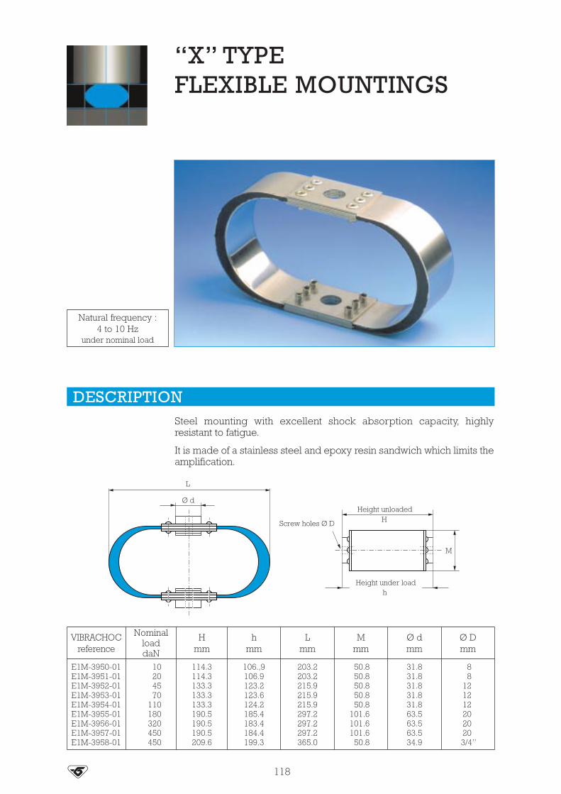
“X” TYPEFLEXIBLE MOUNTINGS
Steel mounting with excellent shock absorption capacity, highlyresistant to fatigue.
It is made of a stainless steel and epoxy resin sandwich which limits theamplification.
DESCRIPTION
118
VIBRACHOCreference
NominalloaddaN
Hmm
hmm
Lmm
Mmm
Ø dmm
Ø Dmm
E1M-3950-01E1M-3951-01E1M-3952-01E1M-3953-01E1M-3954-01E1M-3955-01E1M-3956-01E1M-3957-01E1M-3958-01
10204570
110180320450450
114.3114.3133.3133.3133.3190.5190.5190.5209.6
106.,9106.9123.2123.6124.2185.4183.4184.4199.3
203.2203.2215.9215.9215.9297.2297.2297.2365.0
50.850.850.850.850.8
101.6101.6101.6
50.8
31.831.831.831.831.863.563.563.534.9
88
1212122020203/4”
Natural frequency :4 to 10 Hz
under nominal load
L
Ø d
Screw holes Ø D
Height unloaded
Height under load
H
h
M

ARDAMP®
The ARDAMP series dampers have a spring and piston embedded inhigh viscosity silicone rubber gel which itself is embedded in anelastomer membrane bonded to the case.
Due to their high performances and high shock damping capacityARDAMP dampers are designed to protect fragile electronicequipment, control panels and measuring instruments on groundvehicles, aircrafts, helicopters, civil and military submersible craft.
DESCRIPTION
APPLICATIONS
119
Natural frequency :10 to 25 Hz
under nominal load

120
DIMENSIONS
ARDAMP
S01E1FH781
C01
E1FH76E1FH77E1FH78
E1FH866C01E1FH2507-01
1 tapped holeØ D
1 tapped holeØ D
Ø C
G usable
G usable
He
e
4 mounting holesØ d 4 mounting holes
Ø d
4 mounting holesØ d
1 tapped holeØ D
Ø C
G usable
H
J
H
AA
A
B
B
B
e
h
J
B
B
A
A
J
B
A
Ø C
Ø Amm
ReferenceH
Unload.mm
H approx.under load
mm
Bmm
Cmm
Ø DE
mm
Gmaximm
Jmm
dmm
emm
hmm
Weightapprox.
E1FH781S01E1FH781C01
4243
3941
35 54 43 M5 10 12 4.5 5.5 120 g
E1FH866C01E1FH2507-01
47 46 49.2 65.3 61.5 M6 15 12 5.2 5230 g215 g
E1FH76-01E1FH76-02
7067
6665
63.5 77 70 M10 30 19 24 8.4 7.2 49 390 g
E1FH77-01 86 82 88 110.5 96 M12 40 24 34 8.4 8.5 62 930 g
E1FH78-01E1FH78-02
10298
9995
107.9 132 117 M16 54 25 44 11 9.5 77.5 1.5 kg

121
OPERATING CHARACTERISTICS
ARDAMP
Natural frequency :• axial : 10 to 25 Hz• radial : 10 to 20 Hz.
Damping : 20 % e (E1FH781, 866, 2507-01).17% e (E1FH76, 77, 78).
Amplification factor at resonance : 2.5 to 3 max.These dampers comply with SEFT 001A, AIR 7304, MIL STD 810 C.
SEFT 001 A AIR 7304MIL
STD 810 CNon standardapplications
Shocks andbumpsOZ axis
ReferenceLoad
kg perdamper
AxialFn
in Hz
RadialFn
in Hz
Loadkg perdamper
AxialFn
in Hz
RadialFn
in Hz
Load kgper
damper
AxialFn
in Hz
Load kgper
damper
RadialFn
in Hz
6 ms½ sineshocks
maxinput
g
11 ms½ sineshocks
maxinput
g
E1FH781S01E1FH781C01
0.2-22-5
20-25 15-204 16
1.5-3.53.5-8
10-20 70 g 38 g
E1FH866C01E1FH2507-01
8-15-
10-20-
12-20-
6-8-
20-25-
15-20-
8-
20-
8-155-8
10-206-10
50 g-
27 g-
E1FH76-01E1FH76-02
14-2018-30
10-2012-2011-16
7-129-20
20-25 15-201418
1817
14-2018-30
10-2040 g55 g
22 g30 g
E1FH77-01 20-50 10-20 10-17 30 15 20-50 10-20 50 g 25 g
E1FH78-01E1FH78-02
50-10090-130 10-20
10-1610-15
75100
1011
50-10090-130
10-20 40 g 22 g
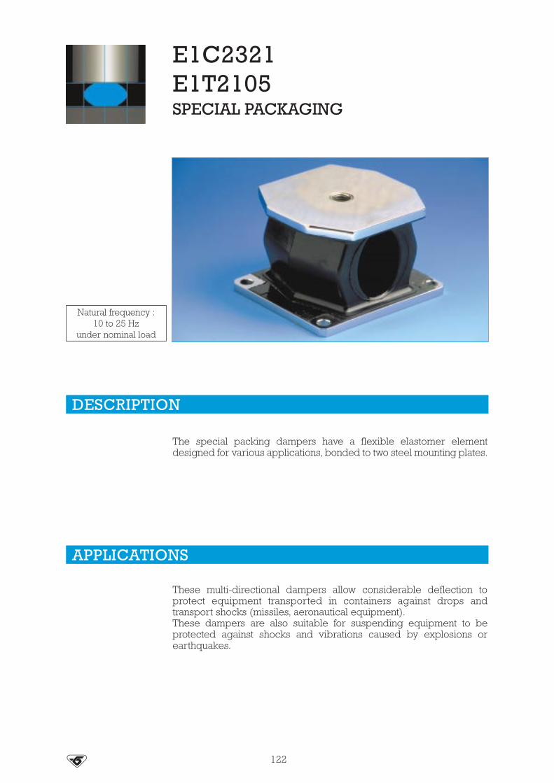
E1C2321E1T2105SPECIAL PACKAGING
The special packing dampers have a flexible elastomer elementdesigned for various applications, bonded to two steel mounting plates.
These multi-directional dampers allow considerable deflection toprotect equipment transported in containers against drops andtransport shocks (missiles, aeronautical equipment).These dampers are also suitable for suspending equipment to beprotected against shocks and vibrations caused by explosions orearthquakes.
DESCRIPTION
APPLICATIONS
122
Natural frequency :10 to 25 Hz
under nominal load

123
DIMENSIONS
E1C2321
OPERATING CHARACTERISTICS
Natural frequency:• axial: 10 to 25 Hz• radial: 10 to 25 Hz.
Maximum permitted excitation at natural frequency of suspension: ± 1.6 mm.Maximum travel available for shocks: - axial 15 mm.
- radial 40 mm.Operating temperature: see table.Weight: 0.3 kg.
70
3
370
4 mounting holesØ 5.5 45.5
unload.approx.
4355
82
BR 60 ShBR 70 ShBR 80 Sh
Reference Axial static loadin daN Damping
Resistance tooils and
hydrocarbons
Resistanceto fatigue
Operatingtemperature
E1C2321S01
E1C2321S02
1-10
2-20*** * * - 54 to + 150°C
E1C2321-01E1C2321-02E1C2321-03
2-205-50
10-100* ** *** - 30 to + 100°C
E1C2321-21E1C2321-22E1C2321-23
2-205-50
10-100*** * *** - 40 to + 90°C
Material(1)
SIL 33 Sh
SIL 55 Sh
CR 60 ShCR 70 ShCR 75 Sh
(1) SIL: Silicone ; CR: Chloroprène-Rubber ; BR: Butadiene-Rubber. 1 kg � 1 daN

124
DIMENSIONS
E1T2105
OPERATING CHARACTERISTICS
Natural frequency :• axial : 10 to 25 Hz• radial : 10 to 25 Hz.
Maximum permitted excitation at natural frequency of suspension : ±1.6 mm.Maximum travel available for shocks : - axial 40 mm.
- radial 75 mm.Operating temperature : see table.Weight : 2.6 kg.
ReferenceAxial static load
daNDamping
Resistance tooils and
hydrocarbons
Resistanceto fatigue
Operatingtemperature
E1T2105S01E1T2105S02
2-204-40
*** * * - 54 to + 150°C
E1T2105-41E1T2105-42E1T2105-43
10-10020-20050-400
* *** ** - 25 to + 90°C
E1T2105-21E1T2105-22E1T2105-23
10-10020-20050-400
*** * *** - 40 to + 90°C
1 tapped holefor screw M16 16 usable
122
8
8
120
4 mountingholes
Ø 10.590unload.approx.
100 122
140

Stiffness (1)(2) (N/mm)Tolerance: ± 10 %
Characteristics
1.21.41.61.82.02.43.03.3
0.40.470.530.60.670.811.1
36404550556575
100
192025
Tolerance: ± 15 %
E: Elast. modul.(MPa)
G: Shear modul(MPa)
ELASTOMERMOULDED PARTS
These parts are usually supplied in VHDS (very high density silicone)rubber and the full reference should include:
- the letter S,- the appropriate grade which corresponds:• to the youngs modulus of the rubber under static compression in
accordance with ASTM D945 (ref. 33 to 77),• or to the stiffness measured on a part (ref. 16 to 25).
These standard VIBRACHOC grades are shown in the following table:
CHARACTERISTICS
SILICONE RUBBER / SPECIAL ELECTRONICS
(1) measured on standardised Ø 19 - h 12.7 mm high part. 1 kg � 1 daN(2) linear region between 1 to 3 mm compression.
Example: E3RP0754S55 flat washer internal diameter 7, external diameter 30, height 6, inVHDS silicone, young modulus 2 MPa ; washer colour: brick red.
Other elastomers may be used: natural rubber, neoprene, EPDM, butyl rubber, nitrile rubber.
125
Reference
162025
3338424855637277
light bluegrey
browndark greenbrick redorange
light greenultramarine blue
yellowdark blue
black
Colour

126
DIMENSIONS
SILICONE RUBBER / SPECIAL ELECTRONICS
FLAT WASHERS
Reference
E3RP2439E3RP3419E3RP2062E3RP3291E3RP2061E3RP2667E3RP2025E3RP2024E3RP2401E3RP2282E3RP2281E3RP2959E3RP2453E3RP2403E3RP3534E3RP2402E3RP3162E3RP2882E3RP0590E3RP2883E3RP0591E3RP2404E3RP0754E3RP2148E3RP2149E3RP2454E3RP2406E3RP2405E3RP0607E3RP0608E3RP0588E3RP0777E3RP2436E3RP0609E3RP2045
2244455566.16.16.46.56.56.56.56.57777777.47.67.7888888888.5
6789
121215221812201211.813.515182512121616303011.517.611.8131618182224262626
10153.4454466432.5
104.5
14.524668367.567.74468446
104
Ø Int.mm
Ø Ext.mm
emm
Reference
E3RP2604E3RP2605E3RP2330E3RP2181E3RP2570E3RP2446E3RP3500E3RP0613E3RP2346E3RP2437E3RP0584E3RP2345E3RP2645E3RP0614E3RP0615E3RP2435E3RP0644E3RP0585E3RP0643E3RP0586E3RP2329E3RP2328E3RP0694E3RP0695E3RP0738E3RP2407E3RP3222E3RP2408E3RP2409E3RP3532E3RP0782E3RP2434E3RP0744E3RP0745E3RP2341
9999.59.59.5
1010101010101010101010101010111112121214141620202122313644.5
1319362024261820212222242526263030343434363617185022302932382938364483
44664446646646
126
1268
124644
126.537
10.535
17333.2
Ø Int.mm
Ø Ext.mm
emm
Ø Ext.
Ø Int.
e

127
DIMENSIONS
SILICONE RUBBER / SPECIAL ELECTRONICS
FLANGED WASHERS
GROMMETS
THREADED STUDS
Reference
E3RP0712E3RP2292E3RP3290E3RP0647E3RP0997E3RP2192E3RP2410E3RP3533E3RP0755E3RP2374E3RP2379E3RP0563E3RP2173E3RP0778E3RP2042E3RP3491E3RP3490E3RP0553E3RP0575E3RP2315
Ø dmm
Ø D1mm
Ø D2mm
Hmm
h1mm
h2mm
3.53.544.25666.57888888.59.5
10111216
1013
98
1812181530181819.82124262418245050
7.5665.8
108.5
101117121313.81314171814172828
4.775.43.3
247
108
1463.57688889
2222
3.23.33.41.7
14464.56322444444
1212
1.53.721.6
10343.5831.55244445
1010
Ø D1
Ø D2
Ø dh2
H
h1
Reference
E3RP2364E3RP0648E3RP0576E3RP3295E3RP3258
Ø D1mm
Ø D2mm
Ø D3mm
A1mm
A2mm
Bmm
44.2588
65.88
1212
88
121818
2.21.725.55.5
2.21.725.55.5
1.61.6436
Ø D1
Ø D3
Ø D2
A2
A1
B
Reference
E3RP0953E3RP0956E3RP2118E3RP0757E3RP0954E3RP0708E3RP0686
Ø Dmm10121620333333.2
Hmm
88
1623263953.5
Lmm
668/9.5
1213.213.212
Ø M
M3M3M5M5M6M6M6
Ø M
H
Ø D
L L

ELASTOMERPLATESE3PEPL
VHDS elastomer sheet.
These sheets may be used for making grommets, washers or anti-vibration mountings for equipment.There is a wide range of VIBRACHOC moulded parts, but in certaincases, such as prototypes - undefined specification, etc, it is oftenadvantageous to determine the suspension using elastomer compo-nents cut from sheet and bonded.
• Overall tolerances:- on the lengths: ± 5%- on the thickness: ± 3%
VIBRACHOC plates should be ordered using the following reference:E3PEPL ❏ ❏ S ❏ ❏ C ❏ ❏ ❏
1 2 3
1: dimension in cm.2: grade (see. table page 126).3: thickness in 1/10 mm.
For example: E3PEPL30S55C060 =• square plate 300 X 300 mm.• 6 mm thick VHDS rubber compound.• grade 55.
For other shapes, sizes or materials, ask us for details.
SHAPEDIMENSIONS
mmTHICKNESS
mm
SQUARE 300 X 300 2, 3, 4, 5, 6, 8, 10
DESCRIPTION
APPLICATIONS
CHARACTERISTICS
SILICONE RUBBER / SPECIAL ELECTRONICS
}}}
128

129
E1E11S**E*E1E12S**E*E1E13S**E*
- VHDS elastomer able to carry loads under compression and traction.- pedestal, washer and shaft in stainless steel.
- protecting electronic equipment, navigation equipment, instrument panels, measuringinstruments, control panels on aircraft, road vehicles and railway trains.
Natural frequency :• axial : 20 to 25 Hz• radial : 20 to 25 Hz.Maximum permitted excitation at natural frequency ofsuspension : ± 0.5 mm.Amplification factor at resonance < 5.Operating temperature : - 54°C to + 150°C.Structural strength corresponds to a continuous accelera-tion of 10 g at maximum load.Maximum axial travel available for shock :E1E11 : + 4mm / E1E12 : + 5 mm / E1E13 : + 7 mm.Weight : E1E11 : 60 g / E1E12 : 120 g / E1E13 : 225 g.
DESCRIPTION
APPLICATIONS
CHARACTERISTICS
SILICONE RUBBER / SPECIAL ELECTRONICS
ReferenceAxial static loads
in daNE1E11S38ECE1E11S42ECE1E11S48ECE1E11S55ECE1E11S63ECE1E11S72EC
1.60 - 2-801.80 - 3.202.10 - 3.802.50 - 4.503.00 - 5.303.50 - 6.20
E1E12S38EDE1E12S42EDE1E12S48EDE1E12S55EDE1E12S63EDE1E12S72ED
3.70 - 5.704.00 - 6.304.60 - 7.105.20 - 8.106.00 - 9.30
6.60 - 10.30E1E13S38EEE1E13S42EEE1E13S48EEE1E13S55EEE1E13S63EEE1E13S72EE
5.50 - 8.506.00 - 9.50
6.50 - 10.507.50 - 12.008.50 - 14.00
10.00 - 16.00
Natural frequency :20 to 25 Hz
4 mountingholes Ø D
J
A
B
Ø C
Ø E
Hunloadedapproxh approx.underload
A B
Gusable
1 tappedholefor screw Ø D
Reference Amm
Bmm
Ø Cmm Ø D Ø E
mmH
mmJ
mmØ dmm
hmm
Gmm
E1E11S ❑❑ EC 25.4 34 28.5 M5 23 29 14 4.3 28 10
E1E12S ❑❑ ED 34.9 44.4 40 M6 34.6 35.6 19 4.3 34.5 12
E1E13S ❑❑ EE 49.2 60.5 57 M8 45 47 23 5.3 45.5 16

130
E1E11S**AL*E1E12S**AL*E1E13S**AL*
- VHDS elastomer able to carry loads under compression and traction.- flange, washer and shaft in steel.
- protecting electronic equipment, navigation equipment, instrument panels, measuringinstruments, control panels on aircraft, road vehicles and railway trains.
Natural frequency :• axial : 20 to 25 Hz• radial : 20 to 25 Hz.Maximum permitted excitation at natural frequency ofsuspension : ± 0.5 mm.Amplification factor at resonance < 5.Operating temperature : - 54°C to + 150°C.Structural strength corresponds to a continuous accelera-tion of 10 g at maximum load.Maximum axial travel available for shocks :E1E11 : + 4mm / E1E12 : + 5 mm / E1E13 : + 7 mm.Weight : E1E11 : 25 g / E1E12 : 75 g / E1E13 : 225 g.
DESCRIPTION
APPLICATIONS
CHARACTERISTICS
SILICONE RUBBER / SPECIAL ELECTRONICS
ReferenceAxial static loads
in daNE1E11S38ALE1E11S42ALE1E11S48ALE1E11S55ALE1E11S63ALE1E11S72AL
1.60 - 2-801.80 - 3.202.10 - 3.802.50 - 4.503.00 - 5.303.50 - 6.20
E1E12S38ALE1E12S42ALE1E12S48ALE1E12S55ALE1E12S63ALE1E12S72AL
3.70 - 5.704.00 - 6.304.60 - 7.105.20 - 8.106.00 - 9.30
6.60 - 10.30E1E13S38ALE1E13S42ALE1E13S48ALE1E13S55ALE1E13S63ALE1E13S72AL
5.50 - 8.506.00 - 9.50
6.50 - 10.507.50 - 12.008.50 - 14.00
10.00 - 16.00
Natural frequency :20 to 25 Hz
1 mounting holeØ D
Ø F
B
Ø C H unloadedapprox.
h under loadapprox.
e
A
G usable
4 mounting holesfor screw Ø d
A B
Reference Amm
Bmm
Ø Cmm
Ø Fmm
Gmm
Ø dmm
emm
Hmm
hmm
Ø Dmm
E1E11S ❑❑ AL 25.4 32 23 25.4 19 3.6 1.5 10 9 5.2
E1E12S ❑❑ AL 34.9 44.5 34.6 38.7 25.4 4.2 1.8 11.5 10.5 6.7
E1E13S ❑❑ AL 49.2 80.5 45 53 38 5.3 2.5 17.75 16.5 8.3

E1E21E1E22E1E23
- VHDS elastomer.- flange and shaft in 18/8 stainless steel.Two Ø K fail safe rings must be provided.
- protecting electronic equipment, navigation equipment, instrument panels, measuringinstruments, control panels on aircraft, road vehicles and railway trains.
Natural frequency :• axial : 15 to 25 Hz• radial : 20 to 35 Hz.Maximum permitted excitation at natural frequency ofsuspension : ± 0.5 mm.Amplification factor at resonance < 4.Operating temperature : - 54°C to + 150°C.Structural strength corresponds to a continuous accelera-tion of 10 g at maximum load.Maximum axial travel available for shock :E1E21 : ± 4 mm for f min / E1E22 : ± 4.5 mm for f min
± 6 mm for f max ± 6 mm for f max.Weight : E1E21 : 9 g / E1E22 : 25 g / E1E23 : 63 g.
DESCRIPTION
APPLICATIONS
CHARACTERISTICS
SILICONE RUBBER / SPECIAL ELECTRONICS
131
Reference Axial static loadsin daN
Frequencyin Hz
Axial static loadsin daN
Frequencyin Hz
E1E21S38ALE1E21S63ALE1E21S77AL
0.15-0.400.30-0.900.40-1.20
15-200.10-0.150.20-0.300.26-0.40
20-25
E1E22S38ALE1E22S63ALE1E22S77AL
0.40-1.000.70-1.700.90-2.20
12-180.20-0.400.40-0.700.50-0.90
18-25
E1E23S42ALE1E23S77AL
0.40-1.201.00-2.90
10-15
Natural frequency :20 to 25 Hz
1 hole for screwØ D
A
LOAD
B
H ± unloadedmaxh under loadapprox.
e
A ± 0.15
Ø C minrecommend.
4 holesØ d
B
EReferenceA
mmB
mmØ Cmm
Ø DE
mmØ dmm
emm
Hmm
hmm
E1E21S ❑❑ AL 25.4 32 24 M4 19 3 0.8 12.5 11
E1E22S ❑❑ AL 34.9 44.5 28 M5 25.4 4 1.5 16.5 15
E1E23S ❑❑ AL 49.2 60.5 42 M6 36 5 2 22 20

E1E31E1E32
- VHDS elastomer.- flange and shaft in 18/8 stainless steel.Two Ø K fail safe rings must be provided.
- protecting electronic equipment, navigation equipment, instrument panels, measuringinstruments, control panels on aircraft, road vehicles and railway trains.
Natural frequency :• axial : 15 to 25 Hz• radial : 20 to 35 Hz.Maximum permitted excitation at natural frequency ofsuspension : ± 0.5 mm.Amplification factor at resonance < 4.Operating temperature : - 54°C to + 150°C.Structural strength corresponds to a continuous accelera-tion of 10 g with maximum load.Maximum axial travel available for shocks :E1E 31 : ± 4 mm for f min
± 6 mm for f max.E1E 32 : ± 4.5 mm for f min
± 6 mm for f max.Weight : E1E31 : 9 g / E1E32 : 25 g.
DESCRIPTION
APPLICATIONS
CHARACTERISTICS
SILICONE RUBBER / SPECIAL ELECTRONICS
132
Reference Amm
Bmm
E1E31S ❑❑ AL 25.4 32
E1E32S ❑❑ AL 34.9 44.5
Ø Cmm
25
35
Ø D
M4
M5
Ø Emm
8.5
13
Fmm
10.5
14.5
Jmm
2
3
Kmm
dmm
25 3.6 3.2 5 4.5 0
35 4.3
emm
1
1.5 4.5 7 6.2 0
Hmm
1.75
2.5
hmm
3.5
5
Min Max
f (mm)
Min Max
j (mm)
Natural frequency :15 to 25 Hz
Reference Axial static loadsin daN
Frequencyin Hz
Axial static loadsin daN
Frequencyin Hz
E1E31S38ALE1E31S55ALE1E31S77AL
0.20-0.700.30-1.000.50-1.70 15-20
0.20-0.400.30-0.500.50-0.90 20-25
E1E32S38ALE1E32S55ALE1E32S77AL
0.30-1.100.60-1.800.80-2.60
0.30-0.700.60-1.100.80-1.60
Ø E
1 tapped holefor screw Ø D1 Ring Ø K
(or device)f
e
4 mounting holesfor screw Ø d
A
A
H unloadedapprox.h under loadapprox. Ø C
Ring Ø K minrecommended
B
F
j
i

E1E41E1E42E1E43
- VHDS elastomer able to carry loads under compression.- base and centre axis in stainless steel.
- protecting electronic equipment, navigation equipment, instrument panels, measuringinstruments, control panels on aircraft, road vehicles and railway trains.
Natural frequency :• axial and radial : 10 to 25 Hz.Maximum permitted excitation at natural frequency ofsuspension : ± 0.5 mm.Amplification factor at resonance < 4.Operating temperature : - 54°C to + 150°C.Structural strength corresponds to a continuousacceleration of 10 g at maximum load.Maximum axial travel available for shocks :E1E41 : 8.8 mm / E1E42, E1E43 : 12 mm.Weight : E1E41 : 22 g / E1E42 : 60 g / E1E43 : 96 g.
DESCRIPTION
APPLICATIONS
CHARACTERISTICS
SILICONE RUBBER / SPECIAL ELECTRONICS
133
Reference Amm
E1E41- ❑❑ EB 25.4
E1E42- ❑❑ EC 34.9
E1E43- ❑❑ ED 49.2
Bmm34 30,5
41.5
57
43
60.5
Ø Cmm Ø D
M4
M5
M6
Ø Emm10
12
21.5
Gmm
6
8
8
Hmm23
33
33
Nmm14.2
20
20
dmm
4.3
4.3
5.3
emm
0.8
1.5
2
fmm
14
18
16
hmm
21
31
31
Natural frequency :10 to 25 Hz
①
ReferenceAxial static loads
in daNE1E41-S38EBE1E41-S63EBE1E41-S77EB
1.20-2.102.00-3.803.00-5.20
E1E42-S38ECE1E42-S63ECE1E42-S77EC
1.75-3.303.20-5.904.40-8.30
E1E43-S38EDE1E43-S63EDE1E43-S77ED
3.10-5.505.40-10.807.50-13.60
① These isolators exist with an oval flange (FB).
Ø E1 tapped holefor screw Ø D
f
e
B
4 mounting holesfor screw Ø d
A
A
H unload. approx.
h under loadapprox
Ø C
Ø C
B
N
G usable
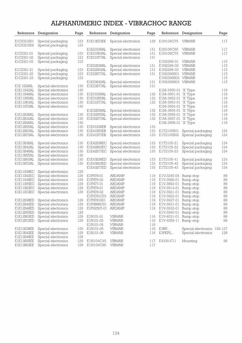
134
ALPHANUMERIC INDEX - VIBRACHOC RANGEReference Designation Page Reference Designation Page Reference Designation Page
E1C2321S01E1C2321S02
E1C2321-01E1C2321-02E1C2321-03
E1C2321-21E1C2321-22E1C2321-23
E1E 1S38ALE1E11S42ALE1E11S48ALE1E11S55ALE1E11S63ALE1E11S72AL
E1E12S38ALE1E12S42ALE1E12S48ALE1E12S55ALE1E12S63ALE1E12S72AL
E1E13S38ALE1E13S42ALE1E13S48ALE1E13S55ALE1E13S63ALE1E13S72AL
E1E11S38ECE1E11S42ECE1E11S48ECE1E11S55ECE1E11S63ECE1E11S72EC
E1E12S38EDE1E12S42EDE1E12S48EDE1E12S55EDE1E12S63EDE1E12S72ED
E1E13S38EEE1E13S42EEE1E13S48EEE1E13S55EEE1E13S63EE
Special packagingSpecial packaging
Special packagingSpecial packagingSpecial packaging
Special packagingSpecial packagingSpecial packaging
Special electronicsSpecial electronicsSpecial electronicsSpecial electronicsSpecial electronicsSpecial electronics
Special electronicsSpecial electronicsSpecial electronicsSpecial electronicsSpecial electronicsSpecial electronics
Special electronicsSpecial electronicsSpecial electronicsSpecial electronicsSpecial electronicsSpecial electronics
Special electronicsSpecial electronicsSpecial electronicsSpecial electronicsSpecial electronicsSpecial electronics
Special electronicsSpecial electronicsSpecial electronicsSpecial electronicsSpecial electronicsSpecial electronics
Special electronicsSpecial electronicsSpecial electronicsSpecial electronicsSpecial electronics
123123
123123123
123123123
130130130130130130
130130130130130130
130130130130130130
129129129129129129
129129129129129129
129129129129129
E1E13S72EE
E1E21S38ALE1E21S63ALE1E21S77AL
E1E22S38ALE1E22S63ALE1E22S77AL
E1E23S42ALE1E23S77AL
E1E31S38ALE1E31S55ALE1E31S77AL
E1E32S38ALE1E32S55ALE1E32S77AL
E1E41S38EBE1E41S63EBE1E41S77EB
E1E42S38ECE1E42S63ECE1E42S77EC
E1E43S38EDE1E43S63EDE1E43S77ED
E1FH76-01E1FH76-02E1FH77-01E1FH78-01E1FH78-02E1FH781C01E1FH781S01E1FH866C01E1FH2507-01
E1N101-01E1N101-02E1N101-04E1N101-05E1N101-06
E1N104C45E1N104C60
Special electronics
Special electronicsSpecial electronicsSpecial electronics
Special electronicsSpecial electronicsSpecial electronics
Special electronicsSpecial electronics
Special electronicsSpecial electronicsSpecial electronics
Special electronicsSpecial electronicsSpecial electronics
Special electronicsSpecial electronicsSpecial electronics
Special electronicsSpecial electronicsSpecial electronics
Special electronicsSpecial electronicsSpecial electronics
ARDAMPARDAMPARDAMPARDAMPARDAMPARDAMPARDAMPARDAMPARDAMP
VIBMARVIBMARVIBMARVIBMARVIBMAR
VIBMARVIBMAR
129
131131131
131131131
131131
132132132
132132132
133133133
133133133
133133133
119119119119119119119119119
116116116116116
117117
E1N104C75
E1N106C60E1N106C75
E1N2296-01E1N2296-02E1N2296-03E1N2296S01E1N2296S02E1N2296S03
E1M-3950-01E1M-3951-01E1M-3952-01E1M-3953-01E1M-3954-01E1M-3955-01E1M-3956-01E1M-3957-01E1M-3958-01
E1T2105S01E1T2105S02
E1T2105-21E1T2105-22E1T2105-23
E1T2105-41E1T2105-42E1T2105-43
E1V-3245-04E1V-3568-01E1V-3892-01E1V-3914-01E1V-3921-01E1V-3922-01E1V-3927-01E1V-3931-01E1V-3932-01E1V-3940-01E1V-4031-01E1V-4059-11
E3RP...E3PEPL...
E4330-F11
VIBMAR
VIBMARVIBMAR
VIBMARVIBMARVIBMARVIBMARVIBMARVIBMAR
‘X’ Type‘X’ Type‘X’ Type‘X’ Type‘X’ Type‘X’ Type‘X’ Type‘X’ Type‘X’ Type
Special packagingSpecial packaging
Special packagingSpecial packagingSpecial packaging
Special packagingSpecial packagingSpecial packaging
Bump stopBump stopBump stopBump stopBump stopBump stopBump stopBump stopBump stopBump stopBump stopBump stop
Special electronicsSpecial electronics
Mounting
117
117117
115115115115115115
118118118118118118118118118
124124
124124124
124124124
888888888888888888888888
126-127128
96

135
ELASTOMER RANGEBARRY CONTROLS

SLM pneumatic mounts are made from synthetic rubber and arelaterally reinforced with steel springs.
The base plate is bored with 4 smooth holes to allow a possible fixingon the ground and the valve allows to inflate the mount in the same wayas an automobile tyre.
• Elastomer body (temperature range -30°C à +180°C) resistant tooils, the majority of solvents and natural ageing.
• The top and bottom plates are available in both steel and aluminium.
136
PNEUMATIC MOUNTS SLM
DESCRIPTION
OPERATION
Natural frequency:3 to 5 Hz
(1)
APPLICATIONS• Industrial plant, compressors, conveyors, vacuum pumps, generators,
air-conditioners, diesel engines, ventilators, presses with fast cycle,machine tools.
• Metrology: measuring apparatus sensitive to the external distur-bances, optical instruments, etc.
(1) Natural frequencies with max/min loads, see : OPERATING CHARACTERISTICS.
The design of SLM mounts gives the following basics characteristics:
• In the event of loss of pressure, the machine will rest on the elastomerbody. The load capacity of the mounting remains unchanged.
• The ratio of horizontal rigidity and vertical rigidity of the SLM is 1:1,which allows excellent stability.
Advantages:
• Eight sizes, capacity range of 10 daN to 10000 daN.• Allow you to level the machine gradually while varying the air
pressure.• Possibility of varying the natural frequency, by varying the air
pressure.

73.2105.2126.7171.2245.4338.1468.4609.6
* Barry Controls references are given as an indication..
Nominalstatic load
daN
76.2106.4130.0174.8254.0342.9469.9609.6
Amm
60.488.9
108.0152.4215.9304.8406.4508.0
Bmm
M10M12M12M12M16M16M24M24
Ø C
1214141419192222
Ø Emm
Ø Fmm
63.562.288.988.988.988.988.988.9
Gmm
25.444.454.176.2
138.2190.5266.7400.1
Ø Hmm
12.712.714.214.214.214.214.214.2
Jmm
3.23.23.23.24.84.86.46.4
Tmm
0.50.71.52.56
11.826.045.0
Weig.kg
SLM-M1A
SLM-M3A
SLM-M6A
SLM-M12A
SLM-M24A
SLM-M48A
SLM-M96A
SLM-M192A
11 - 4534 - 13668 - 272
136 - 545272 - 1090545 - 2180
1090 - 43602180 - 8720
530904 01530904 02530904 03530904 04530904 05530904 06530904 07530904 08
BarryControls *reference
Paulstrareference
DIMENSIONS AND OPERATING CHARACTERISTICS
See current price list for availability of items. 1 kg _~ 1 daN
Ø C
B
A
A
BØ E
Ø F
Ø H
G
JT
0
6
3
4
5
5
4
3
2
120 40 60 80 100 200 400 600 1000 2000 4000 6000 10000
P. b
ar
daN
Hz
5309
04 0
1
5309
04 0
253
0904
03
5309
04 0
4
5309
04 0
5
5309
04 0
6
5309
04 0
7
5309
04 0
8
PRESSURE OF INFLATION FOR STATIC HEAD ANDNATURAL FREQUENCY
1377

138
Recommendations:
• The machine must rest on the supports before they are inflated to the level indicated ondimension " G ".
• Before any diassembling, the SLM mount must be deflated.• The surface of the machine must completely cover the surface (Ø F) of the mount. If it is not
possible, use a separate plate (thickness between 5 and 10 mm, according to the load) anddiameter equal to F + 10 mm. This is to obtain a base on the full surface. It is required for assembly and in the event of an air leakage.
• If necessary, it is possible to fix the supports using the four smooth holes on the bed plate.• Make sure care that the valves are protected.• Never overload the mounts. Always use the recommended load capabilities.
ASSEMBLY
Ø F
G
Correct assembly
Uncorrect assemblies
1 - AV mount 2 - Install the machinery 3 - Inflate the mount
Mount inflated before Floor not level Over inflated mountfixing the machinery

The 22000 mount is made of two parts of elastomer bonded to a centraltube.
• Interior reinforced: cylindrical tube.• Elastomer: chloroprene. Range of five different stiffnesses.
22000 MOUNT
The design of the 22000 mount gives the following basic characte-ristics.
• Elastomer element resistant to oils, supporting axial and radial loadings.
• Axial to radial stiffness of 1 : 1.• Absorb vibrations and reduce noise in all directions.
Advantages :• Good isolation against structural noises.• Chloroprene resistant to oils.• Simple and economical.• Simple to fix.• Five sizes for a load capacity under axial pressure from 15 to 2100 kg
and under radial pressure until 650 kg.• Anti-rebound effect when it is assembled with a washer.
DESCRIPTION
OPERATION
APPLICATIONS22000 mounts can be used in static or mobile applications, such as:pumps, compressors, generators, electronic equipment, HVACequipment, engines with internal combustion, transmissions, plantcabs, radiators, etc.
(1) Natural frequencies with max/min loads, see : OPERATING CHARACTERISTICS.
(1) Natural frequency:8 to 18 Hz
139

20.1
33
40.1
58.4
64.8
19
31.7
38.1
57.1
63.5
Ø C2
mmØ C1
mmØ Bmm
Ø Amm
33.2
47.7
64.8
88.9
123.9
10.4
13.5
16.7
23.8
27
530903 11 / 15
530903 21 / 25
530903 31 / 35
530903 41 / 45
530903 51 / 55
22001-11 / 15
22002-11 / 15
22003-11 / 15
22004-11 / 15
22005-11 / 15
12.3
19.8
22.8
25.4
31.7
9.5
14
22
28.5
32
43
142
313
670
1306
1
1.5
2.3
3
3
31.7
49.2
61.7
73.1
85.8
9.5
12.5
19
25.5
25.5
Fmm
E2mm
DIMENSIONS CHARACTERISTICS
Weightg
Dmm
E1mm
Rmm
BarryControls*reference
Paulstrareference
Supportstructure
Snubbingwasher
Isolatedequipment
Snubbingwasher
D
Ø A
E1
Ø B Ø B
R
E2
D
R
Ø C2
Ø C1 FFØ C1
Ø C2
C1: Ø mounting holeC2: Ø elastomerF: Free heightR: Radius required
140
Isolatedequipment
Supportstructure
See current price list for availability of items. 1 kg � 1 daN
Washer
530903 11 / 15530903 21 / 25530903 31 / 35530903 41 / 45530903 51 / 55
PAULSTRAReference*
39.654.171.398.5
133.3
Ø Amm
10.313.516.723.827.0
Ø Bmm
2.23.44.76.39.5
Cmm
2454
140368991
Weightg
* References given as an indication.
E1 type assembly E2 type assembly
Washers are recommended for the assembly of the mount.They make it possible to carry out debouncing.
Ø A
C
Ø B

141
LOAD/DEFLECTION CURVES IN AXIAL COMPRESSION
5309
03-1
4
5309
03-1
3
530903-12
530903-11
5309
03-1
5
Support structure E2Load per mount
913182227
RadialdaN
AxialdaN
Paulstrareference
BarryControls*reference Axial
daNRadialdaN
FoHz
E1mm
Support structure E1Load per mount
22001-1122001-1222001-1322001-1422001-15
22002-1122002-1222002-1322002-1422002-15
22003-1122003-1222003-1322003-1422003-15
22004-1122004-1222004-1322004-1422004-15
22005-1122005-1222005-1322005-1422005-15
184063
113136
913182227
5979
109172286
22294075
127
95159222390604
4063
102175313
122231350531954
61104156268443
518877
117216092072
109154277404640
15 9.5
12 14
11 22
10 28.5
10 32
FoHz
E2mm
184063
113136
275472
118172
18365681
127
4068
102147227
314772
111163
68136181227272
50100136181263
136227318409545
68100136213300
15 9.5
15 12.5
15 25.5
15 25.5
15 25.5
530903 11530903 12530903 13530903 14530903 15
530903 21530903 22530903 23530903 24530903 25
530903 31530903 32530903 33530903 34530903 35
530903 41530903 42530903 43530903 44530903 45
530903 51530903 52530903 53530903 54530903 55
OPERATING CHARACTERISTICS
The maximum loadings depend on the compression of the assembly by comparing thethicknesses E1 and E2.
See current price list for availability of items. 1 kg � 1 daN
Assembly type E1 and E2

530903 41530903 42530903 43
5309
03 4
4
5309
03 4
5
530903 41530903 42
530903 43530903 44
5309
03 4
5
530903 51530903 52530903 53
5309
03 5
4
5309
03 5
5
530903 51530903 52530903 53
5309
03 5
4
5309
03 5
5
530903 31530903 32
5309
03 3
3
5309
03 3
4
5309
03 3
5
530903 31530903 32530903 3353
0903
34
5309
03 3
5
5309
03 2
5
5309
03 2
4
5309
03 2
3530903 22
530903 21530903 21530903 22530903 23
5309
03 2
4
5309
03 2
5
Assembly type E1 Assembly type E2
142

The CUPMOUNT is made of rubber bonded to two metal reinfor-cements of truncated form.
• Interior reinforcement with tapped hole.• External reinforcements with square base (4 holes).
CUPMOUNT
The design of the CUPMOUNT gives the following basic characteristics:
• The ratio of radial and axial rigidity of the elements is 1/1, whichallows excellent stability.
Advantages:• Four models, load capacity of 1 to 1000 daN.• Support iso-stiffness into axial and radial.• Can be assembled multidirectional. Effective in compression, traction
and shear• Chloroprene resistant to oils.• Easy and fast to install.
DESCRIPTION
OPERATION
APPLICATIONS
Natural frequency:25 to 35 Hz
Engines, pumps, air conditioning, ventilators, transformers...The CUPMOUNT can also be used for suspended ceilings and formobile applications
(1) Natural frequencies with max/min loads, see : OPERATING CHARACTERISTICS.
(1)
143

530906 31530906 32530906 33530906 34
530906 21530906 22530906 23530906 24530906 25530906 26530906 41530906 42530906 43530906 44
Maximum loaddaN
Static applicationMobile application
Paulstrareference
Barry Controls*reference
C1010C1015C1035C1050
6.5142645
C4100C4135C4200C4300
C2020C2040C2060C2075C2090C2125
C3125C3175C3300C3500
6.5142645
132434607292
264868
120144184
7011816025090
125165330
140236320500180250330660
530906 11530906 12530906 13530906 14
49.563.5
143 108
Barry Controls*reference
Paulstrareference
DIMENSIONS CHARACTERISTICS
OPERATING CHARACTERISTICS
Reference 530906
H
A
A
B
B
Ø D
Ø C
GI
TØ E
5876
168124
6075
175133
0.20.44.51.8
C1000
C2000
C3000
C4000
Weightgr
Bmm
Ø Cmm
5.26.4
13.511.9
Ø Dmm
M6M10M16M16
Ø E
20306519
Gmm
28389063
Hmm
18255938
Imm
1.62.34.74
Tmm
530906 11/14530906 21/26530906 31/34530906 41/44
* Barry Controls references are given as an indication.
Amm
* Barry Controls references are given as an indication. 1 kg _~ 1 daN
144

mm
1
54
3
2
0.2
0.40.50.6
0.8
0.3
0 2 3 4 5 6 8 10 20 30 40 8060 100 200 300
15
20
30
40
Hz
daN
Nat
ural
fre
que
ncy
530906 11
530906 12
530906 13
5309
06 1
4
1
54
3
2
0.2
0.40.50.6
0.8
0.3
0 4 5 6 8 10 20 30 40 60 80100 200 300 400 600 1000
15
20
30
40
Hz
mm
daN
Nat
ural
fre
que
ncy
530906 21
530906 22
530906 23
530906 24
530906 25
530906 26
mm
1
456
810
3
2
0.2
0.40.50.6
0.8
0.3
0 20 30 40 60 10080 200 300 400 600 1000 2000 3000 5000
15
10
20
30
40
Hz
daN
Nat
ural
fre
que
ncy
530906 31
530906 32
530906 33
530906 34
mm
1
456
810
3
2
0.2
0.40.50.6
0.8
0.3
0 20 30 40 60 10080 200 300 400 600 1000 2000 3000 5000
15
10
20
30
40
Hz
daN
Nat
ural
fre
que
ncy
530906 41
530906 42
530906 43
530906 44
LOAD/DEFLECTION CURVES IN AXIAL COMPRESSION
Reference 530906 11/14
Reference 530906 21/26
Reference 530906 31/34
Reference 530906 41/44
145
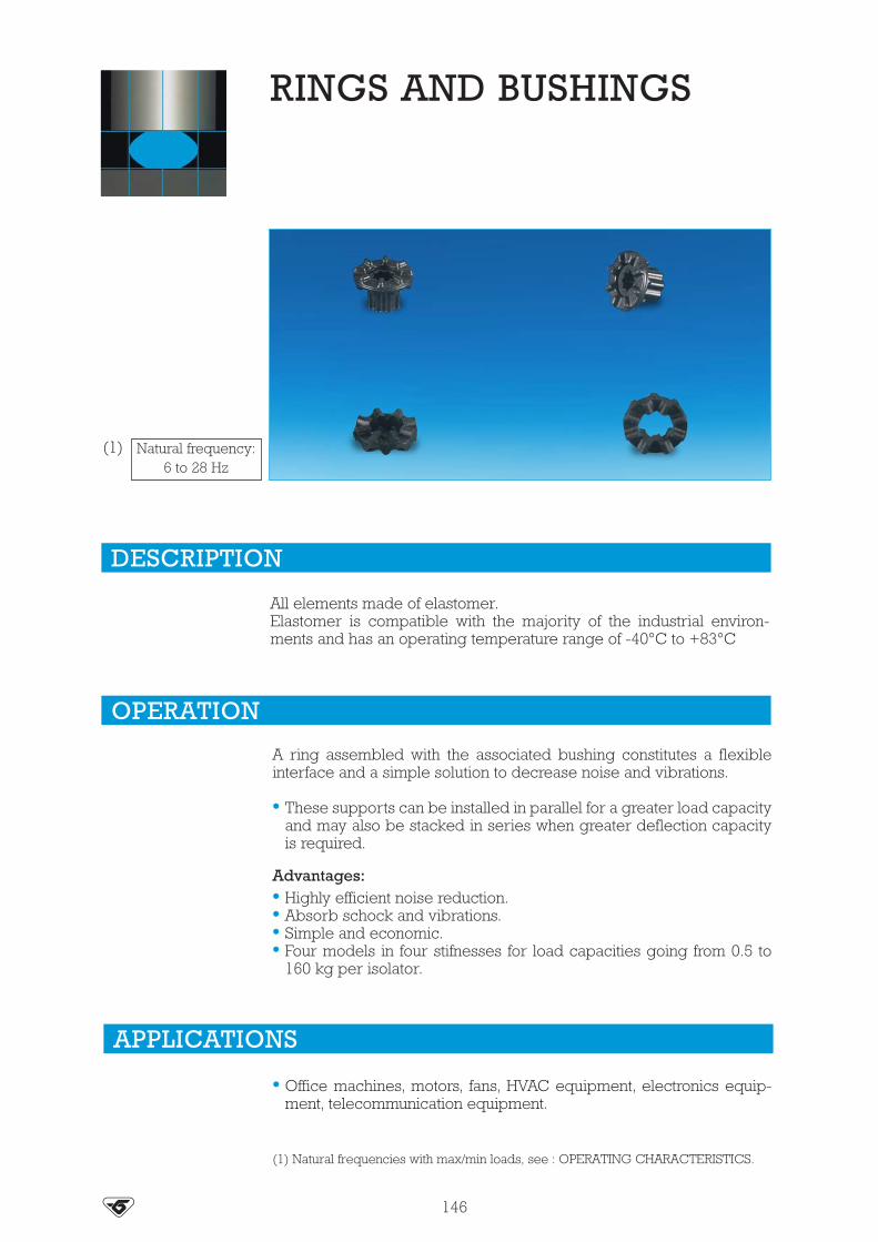
All elements made of elastomer.Elastomer is compatible with the majority of the industrial environ-ments and has an operating temperature range of -40°C to +83°C
RINGS AND BUSHINGS
A ring assembled with the associated bushing constitutes a flexibleinterface and a simple solution to decrease noise and vibrations.
• These supports can be installed in parallel for a greater load capacityand may also be stacked in series when greater deflection capacityis required.
Advantages:• Highly efficient noise reduction.• Absorb schock and vibrations.• Simple and economic.• Four models in four stifnesses for load capacities going from 0.5 to
160 kg per isolator.
DESCRIPTION
OPERATION
APPLICATIONS
• Office machines, motors, fans, HVAC equipment, electronics equip-ment, telecommunication equipment.
(1) Natural frequencies with max/min loads, see : OPERATING CHARACTERISTICS.
Natural frequency:6 to 28 Hz
(1)
146

DIMENSIONS CHARACTERISTICS
A A
A
Ø 31.820.6
Ø 15.9
Ø 55.6
Ø 35
3.3
A
A
Ø 76.2
Ø 31.8
11.9
21.5 10.5
5.6
45.2
Ø 7
3
Ø 1
5.9
2
2
Ø 1
1.5
Ø 2
0.6
6.4
2
2
Ø 2
0.6
14.3
6.6
Ø 1
1.9
Ø 6
.4
2.4
2.4
8.4
16.7
Ø 1
7.5
Ø 9
.5
Ø 3
4.9
Ø 1
9
Ø 3
4.9
2.4
2.4
7.7
4
412
.7
Ø 3
1.8
Ø 4
8.4
2.49.5
22.2
Ø 1
7.5
Ø 1
4.2
Ø 4
8.4
Rings Bushings
Fig. 1
Fig. 2
Fig. 3
Fig. 4
Section A - A
Section A - A
147
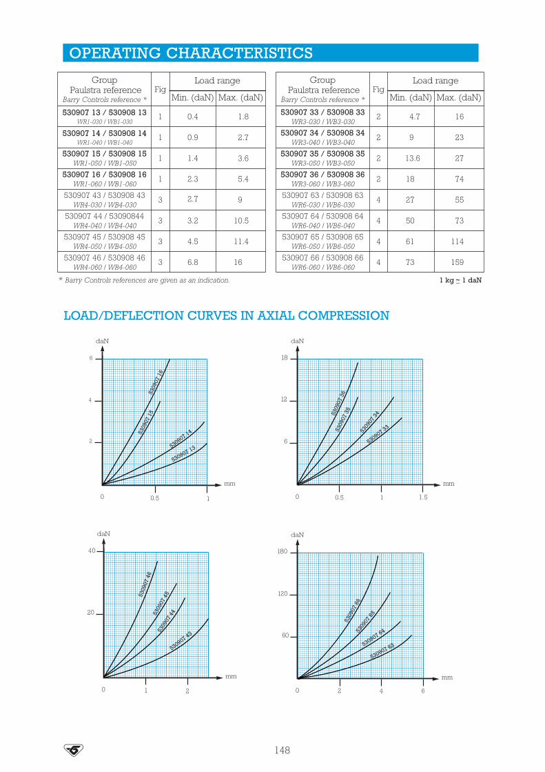
Load range
Max. (daN)Min. (daN)Max. (daN)
Load range
530907 33 / 530908 33WR3-030 / WB3-030
GroupPaulstra reference
Barry Controls reference *
GroupPaulstra reference
Barry Controls reference * Min. (daN)
530907 13 / 530908 13WR1-030 / WB1-030
0.4 1.8
530907 14 / 530908 14WR1-040 / WB1-040
0.9 2.7
530907 15 / 530908 15WR1-050 / WB1-050
1.4 3.6
530907 16 / 530908 16WR1-060 / WB1-060
2.3 5.4
4.7
9
13.6
18
27
50
61
73
16
23
27
74
55
73
114
159
530907 34 / 530908 34WR3-040 / WB3-040
530907 35 / 530908 35WR3-050 / WB3-050
530907 36 / 530908 36WR3-060 / WB3-060
530907 43 / 530908 43WR4-030 / WB4-030
530907 44 / 53090844WR4-040 / WB4-040
530907 45 / 530908 45WR4-050 / WB4-050
530907 46 / 530908 46WR4-060 / WB4-060
530907 63 / 530908 63WR6-030 / WB6-030
530907 64 / 530908 64WR6-040 / WB6-040
530907 65 / 530908 65WR6-050 / WB6-050
530907 66 / 530908 66WR6-060 / WB6-060
2.7 9
3.2 10.5
4.5 11.4
6.8 16
Fig
1
1
1
1
3
3
3
3
Fig
2
2
2
2
4
4
4
4
OPERATING CHARACTERISTICS
LOAD/DEFLECTION CURVES IN AXIAL COMPRESSION
530
907
16
530
907
15
530907 14
530907 13 530907 33
530
907
34 530
907
36 5
3090
7 35
530907 63 530907 64 530
907
65
530
907
66
530
907
46 5
3090
7 45
530
907
44
530907 43
* Barry Controls references are given as an indication. 1 kg _~ 1 daN
148

A flexible fixing resistant to oils, the majority of solvents and ageing.
FLEX-LOC
The design of the FLEX-LOC mount gives the following basiccharacteristics:
• The rubber works in:- compression (axial),- shear (radial),- compression/shear according to the fixing method.
Advantages :• 80 % reduction of vibrational energy transmitted from normal struc-
tural frequencies.• Simple and economical.• Simple to fix.• Light weight.
DESCRIPTION
OPERATION
APPLICATIONS
FLEX-LOC are suitable for the fixing of sheets, frameworks, engines,ventilators, electronic equipment, computers, etc.
149

Nut
Q3Q4Q5Q6Q8
Barry Controlsreference *
Paulstrareference
530909 03530909 04530909 05530909 06530909 07
ClearancecoleØ B
Platethickness G
mm
7,2-7,59,3-9,6
10,2-10,512,7-13,016,5-16,8
0.6-2.50.8-3.30.8-4.31.5-5.01.5-6.5
INm
II ou IIINm
Torque range
Compression/shear
Compression
Static load (daN)
Shear
II ou IIII
0.50.61.03.54.0
0.40.50.60.91.8
111.535
57
101428
2.53.557
14
Q3
Q4
Q5
Q6
Q8
BarryControls
reference *
Paulstrareference
530909 03530909 04530909 05530909 06530909 07
DIMENSIONS CHARACTERISTICS
OPERATING CHARACTERISTICS
M3M4M5M6M8
912151824
Ø Amm
7.29.3
10.212.716.5
Ø Bmm
3.44.45.46.48.4
Ø Cmm
911.514.51722
Dmm
2.533.545
Emm
810.5131519.5
Fmm
* Barry Controls references are given as an indication. 1 kg _~ 1 daN
* Barry Controls references are given as an indication.
F
Ø C
Ø B
D
E
Ø A
Ø B
G
I II III
150
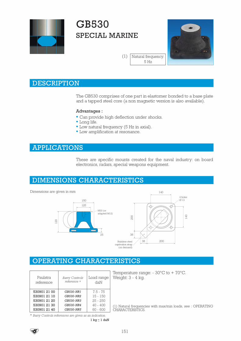
Load rangedaN
7.5 - 7515 - 15025 - 25040 - 40060 - 600
GB530-NR1GB530-NR2GB530-NR3GB530-NR4GB530-NR5
Barry Controlsreference *
Paulstrareference
530901 21 00530901 21 10530901 21 20530901 21 30530901 21 40
The GB530 comprises of one part in elastomer bonded to a base plateand a tapped steel core (a non magnetic version is also available).
Advantages :• Can provide high deflection under shocks.• Long life.• Low natural frequency (5 Hz in axial).• Low amplification at resonance.
These are specific mounts created for the naval industry: on boardelectronics, radars, special weapons equipment.
DESCRIPTION
APPLICATIONS
DIMENSIONS CHARACTERISTICS
OPERATING CHARACTERISTICS
GB530SPECIAL MARINE
Natural frequency:5 Hz
(1)
* Barry Controls references are given as an indication.
150
120
200
120
25 38
140
200
140
38
Dimensions are given in mm
M20 (oradapted M12)
4 holesØ 13
Stainless steelcaptivation strap
(on demand)
Temperature range: - 30°C to + 70°C.Weight: 3 - 4 kg.
(1) Natural frequencies with max/min loads, see : OPERATINGCHARACTERISTICS.
1 kg _~ 1 daN
151

ALPHANUMERIC INDEX - BARRY CONTROLS RANGEReference Designation Page Reference Designation Page Reference Designation Page
530901 21 00530901 21 00530901 21 00530901 21 00530901 21 00
530903 11/15530903 21/25530903 31/35530903 41/45530903 51/55
530904 01530904 02530904 03530904 04530904 05530904 06530904 07530904 08
530906 11/14
GB530GB530GB530GB530GB530
22000 mount22000 mount22000 mount22000 mount22000 mount
SLM mountSLM mountSLM mountSLM mountSLM mountSLM mountSLM mountSLM mount
Cupmount
151151151151151
140-141140-141140-141140-141140-141
137137137137137137137137
144
530906 21/26530906 31/34530906 41/44
530907 13530907 14530907 15530907 16530907 33530907 34530907 35530907 36530907 43530907 44530907 45530907 46530907 63530907 64530907 65530907 66
530908 13
CupmountCupmountCupmount
RingRingRingRingRingRingRingRingRingRingRingRingRingRingRingRing
Bushing
144144144
148148148148148148148148148148148148148148148148
148
530908 14530908 15530908 16530908 33530908 34530908 35530908 36530908 43530908 44530908 45530908 46530908 63530908 64530908 65530908 66
530909 03530909 04530909 05530909 06530909 07
BushingBushingBushingBushingBushingBushingBushingBushingBushingBushingBushingBushingBushingBushingBushing
Flex-LocFlex-LocFlex-LocFlex-LocFlex-Loc
148148148148148148148148148148148148148148148
150150150150150
152

OTHER PAULSTRA DOCUMENTATIONAvailable upon request
AEROSPACEAND DEFENCECATALOG
FLEXIBLECOUPLINGSCATALOG
METALMOUNTINGSCATALOG
FLEXIBLEBUSHESCATALOG
MARINE / NAVYLEAFLET
INDUSTRIALVEHICLESLEAFLET
RAILWAYCATALOG
OFFSHORECATALOG
POWERGENERATIONLEAFLET