page 1 - © richard l. goldman networking the osi model ©richard l. goldman march 29, 2001
TRANSCRIPT

Page 1 - © Richard L. Goldman
NetworkingThe OSI Model
©Richard L. Goldman
March 29, 2001

Page 2 - © Richard L. Goldman
The OSI Model• The OSI (Open Systems Interconnection) Model is
a networking architecture developed by the ISO (International Organization for Standardization). Note: ISO in not an acronym – iso means equal in Greek
• The OSI Model is a helpful reference when developing, discussing, or teaching computer-to-computer communications.
• The OSI Model is only a model. It is not an actual networking architecture or protocol that you would find installed on a computer.

Page 3 - © Richard L. Goldman
OSI ModelSoftw
are
Hardware
7 - Application
6 - Presentation
5- Session
4 - Transport
3 - Network
2 - Data Link
1 - Physical
The OSI Model is a seven layer set of specifications designed to allow all computers to communicate with each other.
The top six layers contain the software that ensures that data is sent and received in a reliable, error-free manner.
The bottom layer consists of the cables, connectors, and equipment that carry the data from one computer to another.

Page 4 - © Richard L. Goldman
OSI ModelSoftw
are
SendingComputer Program
Hardware
7 - Application
6 - Presentation
5- Session
4 - Transport
3 - Network
2 – Data Link
1 - Physical
•When an application in one computer wants to send data to another computer it sends it to the Application layer of the OSI Model.
The data is then passed to each succeeding layer until it is finally transmitted on the Physical layer.
Each layer performs specific processing and packaging functions required to transmit the data.

Page 5 - © Richard L. Goldman
PDU – Packet Data Unit
• As data is passed from layer to layer it is broken down into smaller pieces called:– Packets,
– Data Units, or
– Payloads.
• The official OSI acronym for data placed in packets is a PDU or Packet Data Unit.
• Note: The PDU changes at each layer of the OSI Model as each layer adds its own formatting or addressing to it.

Page 6 - © Richard L. Goldman
OSI Model
Softw
are
7 - Application
6 - Presentation
5- Session
4 - Transport
3 - Network
2 – Data Link
ReceivingComputer Program
OSI ModelSoftw
are
Hardware
7 - Application
6 - Presentation
5- Session
4 - Transport
3 - Network
2 – Data Link
1 - Physical
SendingComputer Program
1 - Physical
The Physical layer of the Receiving computer accepts the packaged data.
It is then passed back through each layer.
The unpacked/reprocessed data is finally delivered to the Receiving Application.
Each layer performs a specific re-processing and/or un-packaging function required to receive the transmission.

Page 7 - © Richard L. Goldman
OSI Model
Computer Program
OSI Model
7 - Application
6 - Presentation
5- Session
4 - Transport
3 - Network
2 – Data Link
1 - Physical
7 - Application
6 - Presentation
5- Session
4 - Transport
3 - Network
2 – Data Link
1 - Physical
Computer Program
file
file

Page 8 - © Richard L. Goldman
OSI Model
Computer Program
OSI Model
7 - Application
6 - Presentation
5- Session
4 - Transport
3 - Network
2 – Data Link
1 - Physical
7 - Application
6 - Presentation
5- Session
4 - Transport
3 - Network
2 – Data Link
1 - Physical
Computer Program
file
Peer Communication
Peer Communication
Peer Communication
Peer Communication
Peer Communication
Peer Communication
Packet orData Frame
Datagram
Segment
Message
Page 9 - © Richard L. Goldman
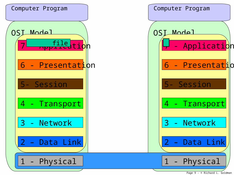
OSI Model
Computer Program
OSI Model
7 - Application
6 - Presentation
5- Session
4 - Transport
3 - Network
2 – Data Link
1 - Physical
7 - Application
6 - Presentation
5- Session
4 - Transport
3 - Network
2 – Data Link
1 - Physical
Computer Program
file

Page 10 - © Richard L. Goldman
OSI Model
Computer Program
OSI Model
7 - Application
6 - Presentation
5- Session
4 - Transport
3 - Network
2 – Data Link
1 - Physical
7 - Application
6 - Presentation
5- Session
4 - Transport
3 - Network
2 – Data Link
1 - Physical
Computer Program
file

Page 11 - © Richard L. Goldman
OSI Model
Computer Program
OSI Model
7 - Application
6 - Presentation
5- Session
4 - Transport
3 - Network
2 – Data Link
1 - Physical
7 - Application
6 - Presentation
5- Session
4 - Transport
3 - Network
2 – Data Link
1 - Physical
Computer Program
file

Page 12 - © Richard L. Goldman
OSI Model
Computer Program
OSI Model
7 - Application
6 - Presentation
5- Session
4 - Transport
3 - Network
2 – Data Link
1 - Physical
7 - Application
6 - Presentation
5- Session
4 - Transport
3 - Network
2 – Data Link
1 - Physical
Computer Program
file

Page 13 - © Richard L. Goldman
OSI Model
Computer Program
OSI Model
7 - Application
6 - Presentation
5- Session
4 - Transport
3 - Network
2 – Data Link
1 - Physical
7 - Application
6 - Presentation
5- Session
4 - Transport
3 - Network
2 – Data Link
1 - Physical
Computer Program
file

Page 14 - © Richard L. Goldman
OSI Model
Computer Program
OSI Model
7 - Application
6 - Presentation
5- Session
4 - Transport
3 - Network
2 – Data Link
1 - Physical
7 - Application
6 - Presentation
5- Session
4 - Transport
3 - Network
2 – Data Link
1 - Physical
Computer Program
file

Page 15 - © Richard L. Goldman
OSI Model
Computer Program
OSI Model
7 - Application
6 - Presentation
5- Session
4 - Transport
3 - Network
2 – Data Link
1 - Physical
7 - Application
6 - Presentation
5- Session
4 - Transport
3 - Network
2 – Data Link
1 - Physical
Computer Program
file

Page 16 - © Richard L. Goldman
OSI Model
Computer Program
OSI Model
7 - Application
6 - Presentation
5- Session
4 - Transport
3 - Network
2 – Data Link
1 - Physical
7 - Application
6 - Presentation
5- Session
4 - Transport
3 - Network
2 – Data Link
1 - Physical
Computer Program
file

Page 17 - © Richard L. Goldman
OSI Model
Computer Program
OSI Model
7 - Application
6 - Presentation
5- Session
4 - Transport
3 - Network
2 – Data Link
1 - Physical
7 - Application
6 - Presentation
5- Session
4 - Transport
3 - Network
2 – Data Link
1 - Physical
Computer Program
file

Page 18 - © Richard L. Goldman
OSI Model
Computer Program
OSI Model
7 - Application
6 - Presentation
5- Session
4 - Transport
3 - Network
2 – Data Link
1 - Physical
7 - Application
6 - Presentation
5- Session
4 - Transport
3 - Network
2 – Data Link
1 - Physical
Computer Program
file

Page 19 - © Richard L. Goldman
OSI Model
Computer Program
OSI Model
7 - Application
6 - Presentation
5- Session
4 - Transport
3 - Network
2 – Data Link
1 - Physical
7 - Application
6 - Presentation
5- Session
4 - Transport
3 - Network
2 – Data Link
1 - Physical
Computer Program
file

Page 20 - © Richard L. Goldman
OSI Model
Computer Program
OSI Model
7 - Application
6 - Presentation
5- Session
4 - Transport
3 - Network
2 – Data Link
1 - Physical
7 - Application
6 - Presentation
5- Session
4 - Transport
3 - Network
2 – Data Link
1 - Physical
Computer Program
e

Page 21 - © Richard L. Goldman
OSI Model
Computer Program
OSI Model
7 - Application
6 - Presentation
5- Session
4 - Transport
3 - Network
2 – Data Link
1 - Physical
7 - Application
6 - Presentation
5- Session
4 - Transport
3 - Network
2 – Data Link
1 - Physical
Computer Program
e

Page 22 - © Richard L. Goldman
OSI Model
Computer Program
OSI Model
7 - Application
6 - Presentation
5- Session
4 - Transport
3 - Network
2 – Data Link
1 - Physical
7 - Application
6 - Presentation
5- Session
4 - Transport
3 - Network
2 – Data Link
1 - Physical
Computer Program
e

Page 23 - © Richard L. Goldman
OSI Model
Computer Program
OSI Model
7 - Application
6 - Presentation
5- Session
4 - Transport
3 - Network
2 – Data Link
1 - Physical
7 - Application
6 - Presentation
5- Session
4 - Transport
3 - Network
2 – Data Link
1 - Physical
Computer Program
file
file
Page 24 - © Richard L. Goldman
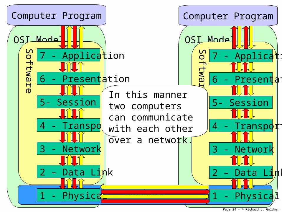
OSI ModelS
oftware
Computer Program
OSI Model
Hardware
7 - Application
6 - Presentation
5- Session
4 - Transport
3 - Network
2 – Data Link
1 - Physical
Softw
are
7 - Application
6 - Presentation
5- Session
4 - Transport
3 - Network
2 – Data Link
1 - Physical
Computer Program
In this manner two computers can communicate with each other over a network.

Page 25 - © Richard L. Goldman
Physical Layer• The Physical Layer consists of
the actual physical components that make up a network:– Cables and connectors– NICs– Hubs– Repeaters
• The Physical Layer is responsible for transmitting, amplifying, and receiving network traffic signals.
• The operation of the Physical Layer is governed by the RS-232-D and 802 protocol standards.
OSI Model
7 - Application
6 - Presentation
5- Session
4 - Transport
3 - Network
2 - Data Link
1 - Physical

Page 26 - © Richard L. Goldman
Data Link Layer - SublayersThe Data Link Layer contains two
sublayers.
• LLC – Logical Link Control– Flow Control
– Error correction
• MAC – Media Access Control– Contains Physical Address
• 12 digit Hex – 1st 6 Mfg, 2nd 6 Unique
– Provides Access Control• Contention
• Token Passing
• Polling
– Controls Logical Network Topology• Ethernet
• Token Ring
• Etc.
OSI Model
7 - Application
6 - Presentation
5- Session
4 - Transport
3 - Network
2 - Data Link
1 - Physical

Page 27 - © Richard L. Goldman
Data Link Layer - Send• The sending Data Link Layer
is responsible for creating data frames that are suitable for transmission.
• To accomplish this the Data Link Layer packages the data into the correct size for transmission and then adds the following components:– Destination Address– Source Address– Control Information– Error Checking Information
OSI Model
7 - Application
6 - Presentation
5- Session
4 - Transport
3 - Network
2 - Data Link
1 - Physical

Page 28 - © Richard L. Goldman
Data Link Layer - ReceiveThe receiving Data Link Layer:
– Checks the frames it receives for errors and acknowledges receipt of each frame.
– The sending Data Link Layer will retransmit a frame if it does not receive an acknowledgement.
– Strips away the components added by the transmitting Data Link Layer and passes the PDU to the Network Layer.
OSI Model
7 - Application
6 - Presentation
5- Session
4 - Transport
3 - Network
2 - Data Link
1 - Physical

Page 29 - © Richard L. Goldman
Network Layer• The Network Layer is
responsible for three services:– Routing – Provide a path to
the receiving computer through one or more intermediate nodes.
– Congestion Control – Route and reroute data to avoid network congestion.
– Internetworking – Providing the means to communicate between two different types of networks.
OSI Model
7 - Application
6 - Presentation
5- Session
4 - Transport
3 - Network
2 - Data Link
1 - Physical
Page 30 - © Richard L. Goldman
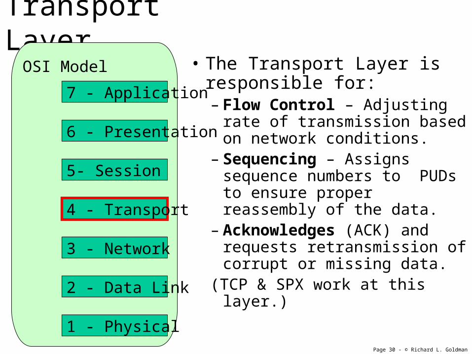
Transport Layer• The Transport Layer is
responsible for:– Flow Control – Adjusting rate
of transmission based on network conditions.
– Sequencing – Assigns sequence numbers to PUDs to ensure proper reassembly of the data.
– Acknowledges (ACK) and requests retransmission of corrupt or missing data.
(TCP & SPX work at this layer.)
OSI Model
7 - Application
6 - Presentation
5- Session
4 - Transport
3 - Network
2 - Data Link
1 - Physical

Page 31 - © Richard L. Goldman
Session Layer• The Session Layer, negotiates,
establishes, and maintains the communications session between two nodes.
• Acts as the traffic cop by regulating which node can transmit and for how long.
• Monitor identification of session participants – permits only authorized nodes to communicate.
OSI Model
7 - Application
6 - Presentation
5- Session
4 - Transport
3 - Network
2 - Data Link
1 - Physical

Page 32 - © Richard L. Goldman
Presentation Layer
• The Presentation Layer translates data into a format that the network can understand.
• Encrypts and decrypts data to provide secure communications.
OSI Model
7 - Application
6 - Presentation
5- Session
4 - Transport
3 - Network
2 - Data Link
1 - Physical

Page 33 - © Richard L. Goldman
Application Layer
• The Application Layer is a set of instructions that act as an interface between a user application running on a computer and the network.
• It is responsible for network:– File transfers– File management– Message handling (e-mail)
OSI Model
7 - Application
6 - Presentation
5- Session
4 - Transport
3 - Network
2 - Data Link
1 - Physical

Page 34 - © Richard L. Goldman
Layer 1 DevicesThe Physical Layer
• Layer 1 Devices (Physical Layer)– Cables and other transmission media– NIC– Transceivers– Repeaters– Hub– MAU

Page 35 - © Richard L. Goldman
Layer 1 Devices (Physical Layer)NICs and Cat. 5 Crossover Cable
Each computer needs a NIC, Network Interface Card, to physically join a network.
This example shows two computers connected with a Cat. 5 crossover cable.
Page 36 - © Richard L. Goldman
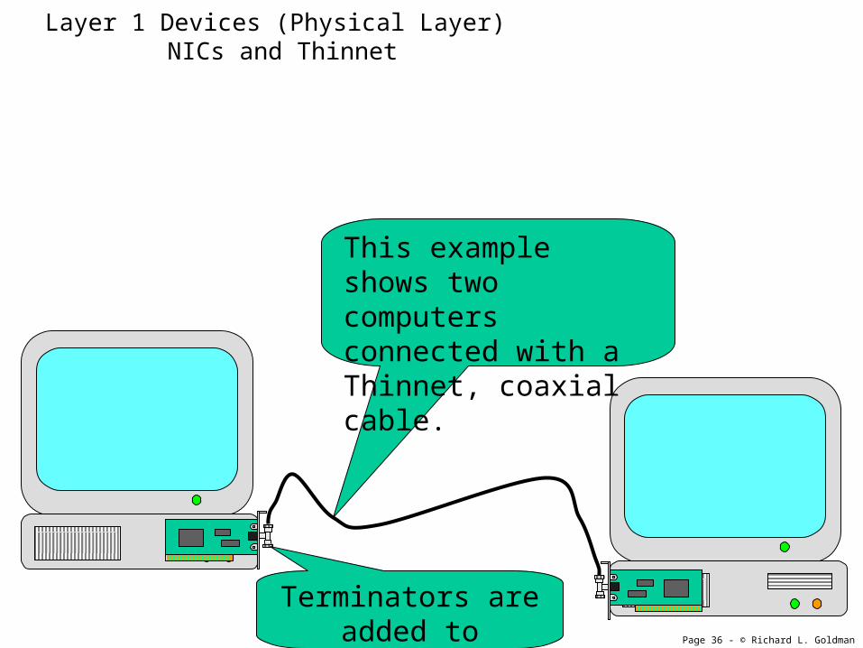
Layer 1 Devices (Physical Layer) NICs and Thinnet
This example shows two computers connected with a Thinnet, coaxial cable.
Terminators are added to complete the circuit.
Page 37 - © Richard L. Goldman
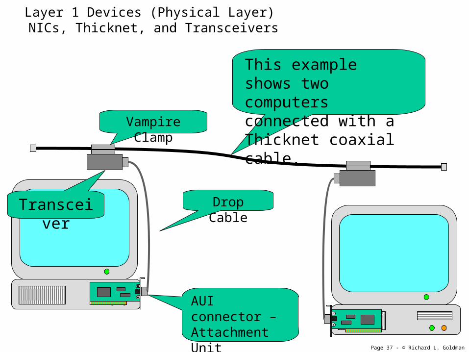
Layer 1 Devices (Physical Layer) NICs, Thicknet, and Transceivers
This example shows two computers connected with a Thicknet coaxial cable.
Vampire Clamp
Transceiver Drop Cable
AUI connector – Attachment Unit Interface
Page 38 - © Richard L. Goldman
OSI Model
Softw
are
7 - Application
6 - Presentation
5- Session
4 - Transport
3 - Network
2 – Data Link
1 - Physical
Computer Program
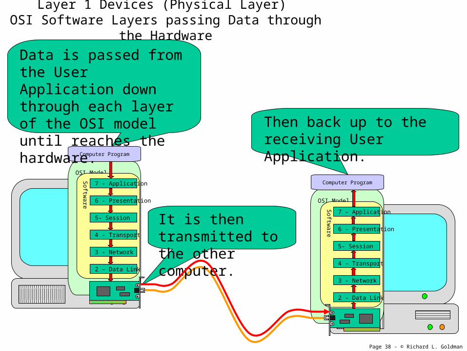
Layer 1 Devices (Physical Layer) OSI Software Layers passing Data through the Hardware
OSI Model
Softw
are
7 - Application
6 - Presentation
5- Session
4 - Transport
3 - Network
2 – Data Link
1 - Physical
Computer Program
Data is passed from the User Application down through each layer of the OSI model until reaches the hardware.
It is then transmitted to the other computer.
Then back up to the receiving User Application.

Page 39 - © Richard L. Goldman
Layer 1 Devices (Physical Layer) Repeater If the distances between the
computers exceed the maximum specified length, a repeater may be used to extend the length of the run.

Page 40 - © Richard L. Goldman
Layer 1 Devices (Physical Layer) Hub
Hubs forward data from one computer to all other computer connected to the hub (broadcast). Hubs function as a multiport repeater by amplifying the signal which can also extends the maximum distance between computes.
Page 41 - © Richard L. Goldman
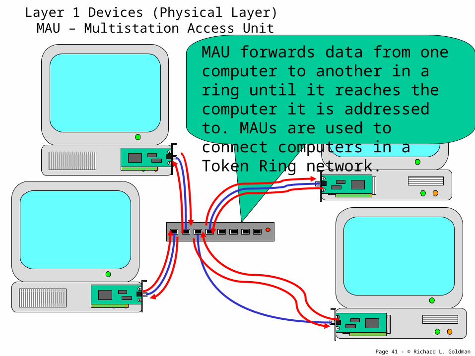
Layer 1 Devices (Physical Layer) MAU – Multistation Access Unit
MAU forwards data from one computer to another in a ring until it reaches the computer it is addressed to. MAUs are used to connect computers in a Token Ring network.
Page 42 - © Richard L. Goldman
Layer 2 DevicesThe Data Link Layer
• Switches are capable of directing network traffic only to the computer it is addressed to.– Also Known As
• Switching Hubs
• Layer 1 Switches
• Bridges are used to pass traffic from one subnet to another while restricting local traffic to its own subnet.

Page 43 - © Richard L. Goldman
Layer 2 Devices (Data Link Layer) Switch
OSI Model
Softw
are
7 - Application
6 - Presentation
5- Session
4 - Transport
3 - Network
2 – Data Link
1 - Physical
A switch uses a MAC Address Table to route traffic to its proper destination. The MAC address table is maintained in the MAC sublayer of the Data Link Layer.

Page 44 - © Richard L. Goldman
Common Network Devices• Layer 5-7 (Application, Presentation, & Session Layers)
– Gateway
• Layer 3 Devices (Network Layer)– Router– Brouter– Layer 3 Switch
• Layer 2 Devices (Data Link Layer)– Switch (AKA, Switching Hub, or Layer 2 Switch)– Bridge
• Layer 1 Devices (Physical Layer)– Cables and other network media– NIC– Transceivers– Repeaters– Hub– MAU

Page 45 - © Richard L. Goldman
Layer #
Layer Name Brief Description Devices
7. Application Network services for user applications
1. Gateway
6. Presentation Data conversion, encryption, compression
5. Session Establish, and maintain communications
4. Transport Maintain packet sequenceRequest missing packets
3. Network Logical addressRoutes packets
1. Router2. Brouter
2. Data Link Physical address 1. Switch2. Bridge LLC
MAC
1. Physical Electrical transmission 1. Cabling2. NIC3. Hub4. Repeater

Page 46 - © Richard L. Goldman
Layer #
Layer Name Brief Description Devices
7.
6.
5.
4.
3.
2.
1.

Page 47 - © Richard L. Goldman
Ethernet Topology Standards
Standard Name Cable Speed Distance IEEE Spec
10BaseT Ethernet UTP/STP 10Mbs 100m 802.3
10Base2 Thinnet Coax 10Mbs 185m 802.3
10Base5 Thicknet Coax 10Mbs 500m 802.3
10BaseF Ethernet over Fiber
Fiber 10Mbs 500m – 2000m
100BaseTX Fast Ethernet UTP/STP-Cat 5
(uses 2 pair)
100Mbs
(Full Duplex)
100m 802.3u
100BaseT4 Fast Ethernet UTP/STP-Cat 3
(uses 4 pair)
100Mbs
(Half Duplex)
100m 802.3
100BaseFX Fast Ethernet over Fiber
Fiber 100Mbs 2000m
100BaseVG “Any LAN”
(Voice Grade)
UTP/STP-Cat 3 UTP/STP-Cat 5
100Mbs 100Mbs
100m
213m
802.12
1000BaseX Gigabit
Ethernet
UTP/STP-Cat 5
or Fiber
1000Mb/s 802.3z