page 1 june, 1961 50 cents detecting microwave
TRANSCRIPT

JUNE, 1961
50 CENTS
DETECTING MICROWAVE -RADIATION HAZARDS
DO YOU WANT WARRANTY WORK?
INDUSTRIAL COUNTING TECHNIQUES
. .. 40 0.0 00 00
n J
:
Ì
-1
i i i
.Ti
i
_i , i
r
i
c
®nnnnnnnnnnn uzo. 77777 " ::: = _ n 7 71-1 '' _I_ 1:1 --r 4-1411. °- N11.
r._ 1-I---1--,.. R- Average ContnuoWaSt i ne-Wave Power n -
-1-1-1 1 -1n-17--: 77 -1 -1 77777. ' n
7n n - -1 -
7-17-1-1 n nnn nn -7-7 ^-_---^
i
_ Ymr.:
-El -1-17 , -1
Aisilidi
" i U00 _a
nn nnn nn1;
HOW TO MAKE MUSIC -POWER MEASUREMENTS
Music Power
44 Watts
1 -i I 7=U-7=U-4-14 --- nnn7n -1-1
7771177 1 -1-1
-177 IT TY-f I I I I 17
77777 n nnnn, 7 n n-
Yd '7C ViHd13QVl1t.' n Is Hl' 1 N tt2. :7I-4:70:t3 17, :7I-4:70:t3
www.americanradiohistory.comwww.americanradiohistory.com

SYLVANIA 6SN7L3TB
with 3 -point plate support
"builds up" your
PROFIT PICTURE -sa
Sylvania extras mean built -in stabil- ity, higher performance and extra - long life - profit -protection for you!
Take, for instance, the new structure that supports each plate at three points to substantially reduce micro - phonics. Or consider how the triode sections are obliquely mounted to reduce catastrophic failure of both sections due to physical shock. Too, Sylvania 6SN7GTB's are built with specially treated micas to reduce interelement leakage; extra -clean welds to cut down on the possibilities of internal shorts.
The technique of grid mounting plus the use of selected alloys for support provides excellent heat dissipation, increased tube reliability. All this plus:
Sylvania "Automount" construction for precise, tight, uniform assembling of tube elements
a "batch" of 100% tests to assure tube quality
tapered pins for fast servicing.
The Sylvania profit "build -up" can work for you. Next time you replace a defective 6SN7GTB, make sure it's with a new ... superior ... Sylvania 6SN7GTB. Order them today from your local Sylvania tube distributor.
Electronic Tubes Division, Sylvania Electric Products Inc., Dept. 236, 1740 Broadway, New York 19, N. Y.
SYLVANIA Subsidiary of GENERAL TELEPHONE & ELECTRONICS ( 7
www.americanradiohistory.comwww.americanradiohistory.com

PICK THE CAREER YOU WANT IN THE WONDERFUL FIELD OF ELECTRONICS
TRAIN AT HOME WITH THE LEADER
Practice with Special Training Equipment Furnished
INDUSTRIAL ELECTRONICS Electronics Principles, Prac- tices, Maintenance prepares you for a career as an Electronic Technician in industry, busi- ness or with the government. Computers, telemetry, automa- tion, missiles, rockets are chang- ing our world, yet all employ the same basic Electronic prin- ciples ... and that is what this NRI course stresses with illus- trated lessons, special training equipment furnished.
TELEVISION -RADIO SERVICING You not only learn to lix radius. 'l'V sets, etc., but. we also show you how to earn spare -time money starting soon after en- rolling. Fast growth in number of sets means money -making opportunities for you in your own spare -time or full -time business, or working for some- one else. NRI makes learning easy, interesting, practical. You get special training equipment :11 no extra cost.
TV-RADIO COMMUNICATIONS
EAEcTOONICS WORLD l. ladi.. .. , .. at l'IIr n I in.
June, 1961
As a technician you help broad- cast the Radio and TV programs you watch at home. NRI pre- pares you for an FCC license for job opportunities operating. servicing, and maintaining AM, FM, TV broadcasting station transmitting equipment; two - way radio for police, marine, aviation, industry. As withother courses, NRI furnishes special training equipment at no extra cost. Mail coupon now.
There is an immediate and growing need for trained technicians in Industrial - Military Electronics, Radio -Television Servicing and Radio -TV Communica- tions. Better than average jobs with high pay, interesting work, bright futures await you in the fast growing industry of the 1960's. Join the many NRI gradu- ates now benefiting from career oppor- tunities in this Electronic Age.
Job Counselors Recommend Job counselors advise investigating Elec- tronics if you are not content with your present job or pay, or are worried about your future. Thousands have moved up to better careers in business and indus- try, in broadcasting stations or in the servicing business through NRI training.
High Pay, Bright Future You must be trained to qualify for higher earnings and advancement. Whichever branch of Electronics you select, you'll find NRI training is the time proved way to get into this big and fast grow- ing industry. NRI "learn -by- practice" methods, using special equipment, make training easier, interesting, practical.
Largest School of its Kind For over 45 years NRI has featured Electronics training, progressing from Radio to TV to Industrial Electronics. NRI supplies training at reasonable cost because it is the oldest, largest home - study school of its kind. Take the first step to a successful new career now. Mail (.01111)11 for FREE CATALOG. National Radio Institute, Washington 16, D.C.
MAIL TODAY r
NRINational Radio Institute Washington 16, D.C. IFE
o
I Please send your catalog. I art interested in training checked bolus .
I Nn reprew.ntative will call. Please Print I0 INDUSTRIAL ELECTRONICS I0 TV -RADIO SERVICING ID TV -RADIO COMMUNICATIONS 1
II Name
I Address
'City Zorn
I state I Accredited Member National Nome Study Council
L :
Age_
-1 nn,p.ln, NIlll.nn It '/.Ilr 1 l ! 1 I . i a -:'. I .. N'1,1,d, Ae l'IlIr.luo ., I11. :\m1 /thee Department. tltlnn,.. on.nl I I SUBSCRIPTION RATES: one year e. S. And poA.e.xlon-. And l .mad: .. ., Pin \merle.n Union enuntrie- R., } ; all other rOraIgn eountrlex S0.00.
1
www.americanradiohistory.comwww.americanradiohistory.com

ELECTRONICS WORLD
Publisher PHILLIP T. HEFFERNAN
Editor WM. A. STOCKLIN, 8. S.
Technical Editor MILTON S. SNITZER, W2QYI
Sc/ e Editor SIDNEY C. SILVER
Associate Editor P. B. HOFFER
Editorial Consultant OLIVER READ, D. Sc., WIETI
Industrial Consultant WALTER H. BUCHSBAUM
Art Editor MILTON BERWIN
Art and Drafting Dept. J. A. GOLANEK
Advertising Manager GEORGE E, MORRISSEY
Midwest Adv. Manager GILBERT J. JORGENSON
Western Adv. Manager ADRIAN WHITED
ZIFF -DAVIS PUBLISHING COMPANY William B. Ziff, President; W. Brad- ford Briggs, Executive Vice -President; Hershel B. Sarbin, Vice -President and General Manager; Michael Michaelson, Vice- President and Cir- culation Director; M. T. Birmingham, Jr., Vice -President and Business Man- ager; Richard Kislik, Treasurer; Charles Housman, Financial Vice -
President.
Editorial and Executive Offices One Park Avenue
New York 16, N. Y. OR. 9.7200
p ill, .11 lliiLlll ....... `a ih Mein bei
Audit Buieau of Circulations
BRANCH OFFICES: Midwestern Of- fice, 434 5. Wabash Ave., Chicago 5, III.; Western Office, 9025 Wilshire Blvd., Beverly Hills, Calif., Adrian Whited, manager. FOREIGN ADVERTISING REPRESENT- ATIVES: D. A. Goodall Ltd., London; Albert Milhado 8 Co., Antwerp and Dusseldorf.
2
JUNE, 1961
VOL. 65 NO. 6
111 IYF(/!U-1(1P/'ISl/l/F-(I11(//(l-(1p(ifIYIII/('ti
CONTENTS INDUSTRIAL AND GENERAL ELECTRONICS
Waveform Quiz Spot News Detecting Microwave- Radiation Hazards How Solutions Are Analyzed Electrically Industrial Counting Techniques Computer Arithmetic Circuits Calendar of Events Recent Developments in Electronics Electronic Crosswords
William E. Bentley 8 Washington Correspondent 24
Tom Jaski 31
John R. Collins 36 Ed Bukstein 39 Ed Bukstein 52
66 74
Bruce Balk 109
HIGH FIDELITY AND AUDIO Los Angeles Hi -Fi Show (Editorial) W. A. Stock/in 6 How to Make Music -Power Measurements Daniel R. von Recklinghausen 27 Cover Story 30 Compact Hi -Fi Power Amplifier Melvin Leibowitz 38 How to Check Speaker Characteristics With a Scope Jim Kyle 68 Sound on Tape Bert Whyte 70 New Audio Test Report (H. H. Scott Model LK -72; Lafayette Model KT -550; Fisher
Model 202 -R) EW Lab Tested Improving the Williamson Amplifier Talbot M. Wright 104
90
SERVICING -TV, RADIO, ETC. Do You Want Warranty Work? Measure D.C. With Your Scope Auto Radios for 1961 Mac's Service Shop Get the New Customer First Service Industry News
34 Lee R. Bishop 42
Max Alth 47 John T. Frye 58
Ernest W. Fair 86 96
TEST EQUIPMENT Novel Glow -Lamp Pulse Generator Michael S. Robbins 46 Outboard VU Meter Harold Reed 54 Adjustable D.C. Power Supply Roy Hartkopf 56
COMMUNICATIONS AND AMATEUR Antennas for Low -Band DX Barry A. Briskman, K2IEG 44 Improving Receiver Sensitivity Jim Kyle, K5JKX 50 Throw Away Your Antenna Pulley Block Howard S. Pyle, W7OE 95 How the FCC Monitors the Citizens Band R. L. Conhaim, I9W7577 99 Voice Procedure For CB Operators Brother Art 110
ELECTRONIC CONSTRUCTION An Accurate Transistorized Tachometer Single -Turn Coil Adjustment
Neil T. Larsen 59 Howard S. Pyle, W7OE 84
(For Information on Next Month's Features, see page 8)
DEPARTMENTS Letters from Our Readers 12 Within the Industry . 18
Technical Books 82 New Products and Literature for Electronics Technicians 112
Net Paid Circulation 235,895 Radio & TV Nests Bailin Secs T, .eviston Nests Trademarks Reg. U. S. Pat. Off.
Copyright J 1961 by 2i11Davis Publishing Company. All rights reserved. SUBSCRIPTION SERVICE, Forms 3 579 and all subscription correspondence should be addressed to Electronics World, Circulation Department, -134 South t'abash Avenue. Chicago 5. Illinois. Please allow at least four weeks for change of address. Include your old address as well as new -enclosing if possible an address label from a
recent issue. CONTRIBUTIONS, Contributors are advised to retain a copy of their manuscripts and illustrations. Contributions should be mailed to the New York Editorial Office and must be accompanied by return postage. Contributions will b. h,md:ed with reasonable care. but this magazine assumes no responsibility for their safety. Any copy nrrepted is subject to whatever adaptations and revisions necessary to meet the requirements of this publication. Pay- ment'c all author's. contributor's. and contestant's rights. title. and interest in and to the material accepted and will sbesmatte at our current rates upon acceptance. All photos and drawings will be considered as part of the
material purchased.
ELECTRONICS WORLD
www.americanradiohistory.comwww.americanradiohistory.com

the Same Sehpol That O The RTS BUSINESS PLAN
NOW
s.P.44141#
Pol'eAt4.
A SPECIAL CUMPACT COURSE COVERING ALL THREE PHASES OF
The Entire Course Is Made Up Of The Following:
35 LESSONS COVERING BASIC
AND INTERMEDIATE ELECTRONICS
9 EQUIPMENT KITS COMPLETE
wiTp TUBES AND BATTERIES
SQLDERING IRON
25 LESSONS COVERING THESE
ADVANCED ELECTRONIC SUBJECTS:
Thyratron Tubes Semiconductors Electronic Symbols and Drawings Voltage -Regulators Electronic - Timers Control Systems X -Rays Photoelectric Devices Dielectric Heating Geiger Counters Pulse Circuitry Clippers and Limiters Multivibrators Electronic Counters Radar Magnetic Amplifiers Analog - Computers DC Amplifiers Digital Computers Storage Systems Input and Output Devices Servomechanisms Telemetering 60 EXAMINATIONS
UNLIMITED CONSULTATION SERVICE
KIT MANUALS
DIPLOMA UPON GRADUATION
AND MUCH
RTS' Membership in The Association of Home Study Schools is your assurance of Reliability, Integrity and Quality of Training.
MORE ...
BASIC INTERMEDIATE ADVANCED DESIGNED FOR THE BUSY MAN OF TODAY
This is MODERN training for the MODERN man. You'll find no "horse and buggy" methods here. Every page of this streamlined course is devoted to important Electronics principles and practical projects. You'll be amazed how fast you grasp Electronics the RTS way. RTS has combined modern THEORY and PRACTICE to make this the finest training program of its kind available!
SATISFIES NOVICE, TECHNICIAN OR HOBBYIST Whether you're new to Electronics or an old "pro," chances are you'll find this to be the ideal course for you. The novice will appreciate the completeness of the training. It starts with the most basic considerations, covering each important point thoroughly, yet concisely. The technician will enjoy the practical review of fundamentals and profit from the 25 advanced subjects covered.
RTS GIVES YOU "TOP MILEAGE" FOR YOUR TRAINING DOLLAR
The price quoted below buys EVERYTHING - there are no extras to pay for. RTS has gone "all out" to give you the best training value in America. Why pay hundreds of dollars for training such as we offer when it's avail- able for this LOW PRICE? If you can find a better training bargain ... BUY IT!
CAN BE COMPLETED IN MONTHS INSTEAD OF YEARS
Some students will complete this course with "Jet- Like" speed but we allow up to two years if your circumstances require it. You study at your own rate. You are ENCOURAGED but not pushed. You'll find the lessons professionally written but easy to understand. LET US SEND YOU ONE OF
THESE LESSONS ALONG WITH YOUR CAREER BOOKLET SO YOU CAN SEE
FOR YOURSELF. NO OBLIGATION!
RTS ELECTRONICS DIVISION 815 E. ROSECRANS AVENUE
LOS ANGELES 59, CALIFORNIA
Est. 1922
Rush Coupon
for-FREE
FACTS!
*TERMS ALSO AVAILABLE
AS LITTLE AS ... $5500 DOWN
$500 PER MONTH
THE FIRST TRAINING KIT IS SENT
IMMEDIATELY UPON ENROLLMENT
DON'T LOSE OUT - FIND OUT! RTS ELECTRONICS DIVISION Dept. EW 61
815 E. ROSECRANS AVENUE LOS ANGELES 59, CALIFORNIA
Rush me full information by return mail. (Please Print)
Nome _
Address
City _. _ _
Zone _ State
NO SALESMAN WILL CALL ON YOU! June, 1961 3
www.americanradiohistory.comwww.americanradiohistory.com

NOW...A Complete Line of Built -in Amplifier clears up snow, improves
ELECTRONIC FM
MODEL PF -T FM POWERTRON TURNSTILE Non -directional FM antenna with 16 DB gain in all directions over a folded dipole. Has unique offset mount and comes complete with built -in transistorized amplifier and TV -FM coupler.
NEW, POWERFUL TRANSISTORIZED FM
POWERTRONS WITH FM -TV COUPLERS For the first time, FM antennas with built-in transistor- ized amplifiers are available for long range FM reception. Winegard offers two models -FM Powertron Turnstile (omni- directional) and the FM Powertron Yagi (directional). Both models have two 300 ohm terminals on the amplifier: one for down -lead connection to the set and one for connection to a TV Powertron antenna.
MODEL PF -e FM POWERTRON VAGI This is the world's most powerful FM antenna. Makes weak signals come in like "locals ". Has 25 DB gain over folded dipole. Eight elements with exclusive Winegard "tapered T" driven element. Built -in TV -FM coupler allows you to couple into TV Powertron with only one power supply. Complete with built -in transistorized amplifier.
ELECTRONIC FM
In addition to three all- channel (VHF) Powertron antennas, Winegard now offers you 14 cut -channel and broad band Powertron yagis and two FM Powertrons. Each of these high gain antennas has the following important features:
1. Electronic amplifier for unprecedented antenna gain. 2. Amplifier connected directly to the yagi "Tapered -T"
driven elements for best possible signal -to -noise ratio. 3. Linear frequency response for crisp, clear black and
white and brilliant, true color reception.
ELECTRONIC ALL - CHANNEL YAGIS . will greatly improve every channel. Weak, faded pic-
tures become crisp and clear. "Good" channels will be even better. In many areas you'll watch channels you couldn't possibly see before. Because Powertrons are powerful enough to drive up to 10 TV sets, you can have plug -in outlets in every room ... and in many locations you can install a Powertron lower than other antennas.
POWERTRON MODEL P -44 14- Elements
POWERTRON MODEL P-44X
21-E lerne nls
POWERTRON MODEL SP -44X
30- Elements
+/ i
www.americanradiohistory.comwww.americanradiohistory.com

Winegard Electronic Antennas contrast... gives you greater reception
4. Gold Anodized finish for permanent corrosion protec- tion and fine appearance.
5. Deluxe quality materials and workmanship. Try a Powertron and see for yourself. Take a field strength meter reading with your present antenna and then take a Powertron reading. When you see the meter jump 5 to 10 times ... and see the sharp, contrasty reception you get, you'll be convinced ... and so will your customers.
"Amplifies the Signal at the point
of Interception"
MODEL SP -44X "By FAR world's most powerful all- channel antenna"
WINEGARO "SIX SET"
TV COUPLER
With the Powertron, hook up 3, 4, 5, or 6 sets by adding a Winegard 'Six - Set". Here's the only 6 tap coupler on the market. Six no -strip terminals give you instantaneous taps with complete elec- tronic isolation. Model LS -63.
ELECTRONIC Cut -Channel
TV
distance!
Each channel amplified individually. No antenna couplers needed!
NEW, TRANSISTORIZED CUT - CHANNEL YAGI
POWERTRONS FOR THE FINEST INSTALLATIONS
Here are the highest gain (28 db) TV antennas ever made! Each is powered by a built -in transistorized amplifier. Because TV signals are amplified right at the point of interception, you get the best possible signal -to -noise ratio . . . resulting in the ultimate in reception!
Each Powertron yagi amplifier has two 75 ohm coaxial connec- tors: one for the down -lead to the power supply and one from the built -in coupler for connection to another Powertron yagi.
Because of the built -in mixing coupler, they can be connected directly to each other without interaction. The negligible power consumption of these transistorized antennas (.05 watt each) means you can tie as many as 8 Powertron yagis together and run them all from one power supply on one down -lead.
There are six (8- element) cut -channel and broad low band models -eight (12- element) cut -channel and broad high band models. Ideal for hotels, motels, apartment buildings or wherever the finest installation is needed.
¡1m egwrl ANTENNA SYSTEMS
Winegord Co., 3003 -6 Kirkwood St., Burlington, Iowa
Write today for technical bulletin on Winegard's complete ©1961 line of Powertron antennas. Ask your distributor for details.
www.americanradiohistory.comwww.americanradiohistory.com

NOW! A down -to -earth guide to
MODERN TEST PROCEDURES
Alternate Test Methods Cautions Correct Instrument Usage Readings Connections and Control Settings.
Test Techniques
,'°' Time -Saving Methods
C BAS
.. and oil the rest!
ELECtßtpI
t01 ES
Almost anyone can re- fair TV -. radios and other elect,. equipment AFT-
ER the instil a has been located. The trick is to know how to spot troubles in the first plate -and that means knowing haw to use in- struments fast and accurately. Actually it's amazing what you can do with only a few in- slrumeut -- providing you know how to Ilse dif- ferent kinds for the same fob: how to select the right ones: where to use them: how to connect them into eirettits: how to set controls: how to read them: and haw to follow pro fessinned lest procedures every step of the way. And that's exactly what this new '118 -page book with its more that, 190 how-to-do-it pictures, procedure sketches and pattern designs tearhe- you.
IT'S WHAT YOU KNOW ABOUT USING INSTRUMENTS THAT COUNTS!
BASIC ELECTRONIC TEST PROCEDURES by Rufus Turner helps you learn to troubleshoot any eirettit, equipment or coral 'nt in half the u -ua l I ime. t'nyers different methods of doing spccinc jobs. For instance. you learn to check distortion by the 'cope. rejection filler. har- nmlic- d ist ort i oil meter, wave analyzer or audio oscillator methods. You learn to make resistan e measurements with a current- meter. a volt-am- meter. a volt -linter. an ohmmeter. or via the bridge method ... and so on.
Subjects include current checks; power. capac- itance. inductance. resistance. AF. RF, phase. dis- tortion. and modulation measurements: tube and semi -conductor testing: audio amplifier tests: sen- sitivity. RF gain. fidelity. AVC voltage, operating voltage checks. etc.: visual alignment techniques -even transmitter and industrial electronic mea- surement procedures. Price only 58.00.
CONSIDER OSCILLOSCOPES for instance! Simplified explanations of modern oscilloscope
techniques show how to use your 'scope as a volt- meter current meter, variable frequency oscillator, etc., or for making RF, phase or AM measurements; for distortion and deflection checking; square wave testing; visual AM and FM alignment and for many other jobs. Every detail is explained -from making connections to analyzing patterns.
INDUSTRIAL ELECTRONIC TESTING, too! STILL ANOTHER BIC FEATURE is the book's use-
fulness in acquainting you with industrial electronic test techniques - including testing non -electronic phenomcra sup .t as strain, pressure and others.
Price only $8.00
PRACTICE 10 DAYS . . . FREE!
Dept. RN -61, Teshnisol Division, 623900 HOLT, RINEHART and WINSTON, Int., 3$3 Madison Ave., New York 17, N.Y.
Send BASIC ELECTRONIC TEST PROCE- DURES ¡708933 ¡ for 10 -day FREE EXAMINA- TION. If I decide to keep book. I will then send you $8.00 plus postage in full payment. It not. I will return book postpaid and owe you nothing. ¡SAVE: Send $8.00 with your order and Rine- hart pays the postage. Same 10 -day guarantee with your money promptly refunded If you're not more than satisfied with book.)
S.UIF
ADDRESS
CITY. 'ZONE, STATU recur .. l.- .:n .- f order or*. Prier '8,50.
Offer expires Jan. 31, 1962 -1
... for the Record By W. A. STOCKLIN
Editor
Los Angeles Hi -Fi Show ALMOST as far back as we can re-
member, some of our staff have cov- ered the major hi -fi shows across the country. We have seen shows in Los Angeles, San Francisco, Chicago, To- ronto, Ottawa, New York, and Wash- ington. In recent years, we've confined our efforts to the two major shows presented by the Institute of High Fi- delity Manufacturers Inc. -either in Los Angeles or San Francisco in the Spring and in New York in the Fall.
\Ve have just returned from the re- cent Los Angeles Show and it was one of the most interesting and informa- tive presentations we have witnessed in many years. It was held in a group of small cottages on a 27 -acre plot on the Ambassador Hotel grounds. The setting was ideal in that the cottages were considerably separated, eliminat- ing the problem of the sound from one exhibitor interfering with another. It was relaxing in that there was no hustle and bustle because of the spaciousness of the grounds.
There were 68 exhibitors. If one were to spend four minutes in each exhibit, it would have taken approximately 41,z hours to see the complete show. The attendance was good; approximately 30.000 highly interested, intelligent in- dividuals viewed the displays. No longer were we asked the question of whether "hi -fi or stereo is better."
One of the most discussed topics among the various manufacturers and the press was the status of FM multi- plex. The FCC has been field- testing a number of FM multiplex systems, and all of us in the industry expected a final choice early this year. There is some disappointment that an announce- ment has not been made as yet. There is a feeling that an FCC decision has been made. but the announcement is being withheld until standards for broadcasting are completed. The feeling is that the decision will favor the system proposed by General Electric or Zenith, or a combination of the two. Both of these systems are similar. The industry, of course, is not asleep in that a lot of design work is being done at the present time and multiplex adapter units should be on the market shortly after the FCC choice is announced.
All of the hi -fi manufacturers had some new products on display. These were either new designs replacing older models or new products added to round
out their lines of equipment. On all the new items we saw, it was a pleasure to note the advances made in cabinet styl- ing and improved electronic perform- ance providing better hi -fi reproduc- tion.
Many of the kit manufacturers are becoming aware that some of their cabi- net and panel designs are no longer attractive to the buyer. They are mak- ing great strides in improving appear- ance so that. in many cases, a kit no longer looks like a kit.
Another point one became aware of is that power ratings on integrated stereo units are getting higher and higher. In the early days of monophonic sound reproduction, we had low -power amplifiers and, as time went on. the power ratings on amplifiers increased steadily. Integrated amplifiers have also had their powers boosted so that now we have 60 to 70 watts per chan- nel.
There were some items displayed that particularly attracted our attention. The Harman- Kardon "Citation" speaker systems, designed by Stu Hegeman, produced a good stereo effect throughout the entire room. This was no doubt due to the omnidirectional radiation from the vertically directed speakers. Rek -O -Kut also showed a new speaker system in a cabinet ap- proximately 2 feet wide, 30 inches high, and a mere 4 inches deep. The sound was radiated equally from the front and rear. The sound is projected against the walls of the room and produces a some- what omnidirectional pattern that gives a good stereo spread.
Transistors are beginning to appear in hi -fi equipment. Transi- Tronics dis- played an all- transistor amplifier and tuner. The amplifier was of moderately low power but, in time, transistor cir- cuits will have higher power outputs with good quality.
Superscope, marketing Sony prod- ucts, displayed a new tape machine with a completely transistorized pre - amp and Weathers also featured a transistor preamp for their phono cart- ridge.
There were a good many other im- pressive products, too numerous to mention, that were of interest to us. All in all, it was a terrific show and congratulations are in order to the Institute of High -Fidelity Manufac- turers Inc. for their presentation. -t-
6 ELECTRONICS WORLD
www.americanradiohistory.comwww.americanradiohistory.com

il/EUJ- simp /y year kniuht -k OF
ts' ''..
talk of the kit world... only at 411 /ED '.
.
measures engine speed,
0 -8000 rpm
New Money- Saving Electronic Tachometer Kit 3% Accuracy Regardless of Temperature or Voltage Variations
Until Aug. 1
Si 995 Another KNIGHT -KIT first -a precision tachom- eter in money- saving, easy -to -build form. Helps you drive at your best engine speed efficiency, like the professionals. Transistor switching and
No Money Down Zener diode regulator contribute to exceptional 3' ; -of- full -scale accuracy, regardless of voltage or tempera- ture changes. Operates with 4, 6 or 8 cylinder automotive engines; simple installation. Ideal also for outboard marine engines using battery or magneto ignition system from 2 cycle 2 cylinder and up. Big illuminated D'Arsonval meter; 0 -8000 rpm scale; separate reference pointer may be preset to any desired speed. For 12 -volt systems only. With cables, mounting hardware, wire and solder. Shpg. wt., 2 lbs. 83 Y 944. For negative ground systems (American cars). 83 Y 980. For positive ground systems (Foreign cars) No Money Down, Introductory Price EITHER TYPE $19.95
SEE DOZENS OF GREAT
knight -kit BUYS in
Allied's Summer Sale Book! Make your money- saving selections from page after page of great KNIGHT -KIT values and special offers! Save most on the best in build -your -own Stereo, hobby, instrument and Ham kits. Also see terrific closeouts on tape recorders, phonos, rec- ords and tape; specials in radios, cam- eras, TV accessories, Citizens Band radio, amateur gear, P.A., test instru- ments, tools and electronic parts. Send coupon today!
it's WIRELESS - just plug in and TALK!
Deluxe Wireless Intercom System Kit at Lowest Cost Works Anywhere Without Wires -No Installation!
This easy -to- assemble intercom operates without PAIR installation or wiring -just plug into any AC or DC wall outlet for step -saving communication! Change locations easily- anywhere. Ideal for home, office or store. In the home, you can corn- NO money Down
municate with nursery, garage, basement or patio. In office or shop, provides time -saving communication. Will operate between adjacent buildings that are on same electric- company line transformer. Perfect for baby sitting. Features power - line noise silencing circuit for absolutely quiet "standby "; premium quality throughout. Has Talk- Listen switch, with lock -on feature for constant listening. Handsome cream -toned plastic cabinet, 9 x 536 x 5,W. Can be used in systems con- sisting of 2 or more units, as desired. Shpg. wt., 33,6 lbs. 20 YX 272 -2. Complete 2- Station System. NET $37.90 83 Y 941. Additional Station. NET EACH $18.95
1190
1 ,.D Send FREE Allied Sale Book No. 205
Ship me the following:
SEND 83 Y 944 Tachometer Kit. 20 YX 272 -2 Intercom System
FOR IT CI 83 Y 980 Tachometer Kit. 83 Y 941 Intercom Station
SAVE AS NEVER BEFORE on everything in Electronics - hundreds of special bargains - dozens of new products! Write for this big value- packed Sale Book today!
ALLIED RADIO, Dept. 31 -F1
100 N. Western Ave., Chicago 80, III.
NOW!
ALLIED RADIO June, 1961
S.... enclosed
1
Name PRINT
Address
City Zone State J 7
www.americanradiohistory.comwww.americanradiohistory.com

Announcing the New
y aM c
Communication Band Antenna Line
FOR THE 144 -174 MC BAND
ROAN tati,o+v 6.1 DB GAIN STACKED DIPOLE
BASE STATION ANTENNA
1 The first mass produced stacked dipole array - the Hy -Gain Model SD -150 - available at amazingly low price. Produces highest gain (6.1 db) of any commercially manu- factured 150 me antenna. With 9.5 DB gain in one favored direction with a slight reorientation of staggered dipole positions. All aluminum (wl: 19 lbs.); complete factory pre - assembly. Constructed to withstand 100 mph winds with ?z" radial ice load. I ridite treated for re- sistance to corrosion.
Ss WAVE 3.4 DB GAIN
. COMMERCIAL GPG -150 DUTY $t77O GROUND PLANE net
Hy -Gain Model GPG -150 is an extended ,5- wave ground plane developing 3.4 DB omni- directional gain. All aluminum (wt. 4 lbs.). Ruggedly built to withstand 100 mph winds at 1.4" radial ice load. Completely indite treated.
1/4-WAVE STANDARD UNITY GAIN GROUND PLANE
Lowest cost base station antenna available - yet built to commercial duty standards. All aluminum - indite treated. Ideal for small two -way systems when price is impor- tant. Model GP -150.
GP -150
$5.40 NI.t.
MW-150 $2.15 net
Mobi,P UNITY CAIN Ss -WAVE
ROOFTOP MOUNTED WHIP
SD 50
$125 70
Net
New design stainless steel Model MW -150 ? -wave rooftop mounted vehicular whip.
tt High impact cycolac molded base mounts
, easily from top of roof with unique posi- tive grip locking mechanism. Solderless
1 connector for RG58U cable. Whip only is easily replaceable.
3.4 DB GAIN ss -WAVE ROOFTOP MOUNTED WHIP
r Double effective power both receivng and transmitting with the Hy -Gain MWG -150 mobile whip. Extremely flexible stainless steel whip only 52" high. Hermetically sealed matching inductor. Single hole top mounting base and solderless RG58U connector.
MWG -150
5e.97 nec
WRITE FOR COMPLETE LITERATURE, SPECIFICATIONS ON YOUR
LETTERHEAD DIRECT TO
antenna products
2nd and Y Street LINCOLN NEBRASKA
COMING NEXT MONTH ELECTRONIC AIR PURIFIERS Just hou' good are the "electronic" air purifiers being sold in supermarkets, drugstores, and appliance shops? Do they do the job for the allergic person? Here is a careful survey of their ad- vantages and drawbacks as well as de- tails on available electronic systems.
BREAKTHROUGH IN THERMOELECTRICITY This important new method of energy conversion promises increasingly wide- spread applications for power genera- tion and for heating and refrigeration in the home. A leading research engineer brings you up to dale on the status of the art.
DON'T WASTE YOUR CB POWER Your CB transceiver must be properly matched to its antenna for maximum range. Here is how to avoid power -wast- ing installations. Standing waves, their causes and cures, are thoroughly ex- plained in this useful article for the Citizens Band operator.
HUM ELIMINATION IN OSCILLOSCOPES Problems in interpreting and measuring waveforms that are modulated by hum are clearly presented, along with the techniques that may be used in elimi- nating or reducing this extraneous signal.
AUTOMATIC HEADLIGHT DIMMER An inexpensive accessory for your car. It dims your headlights automatically upon the approach of another car -but
is so designed that the circuit may be overridden by the driver in case of emer- gencies.
SIMPLE SQUARE -WAVE GENERATOR An easy -to -build test unit for the service technician. Two resistors, a tube, and transformer are all the parts required.
ECONOMY HI -FI AMPLIFIER Build this simple. inexpensive 10 -watt monophonic amplifier and phono prea,np for use with any high -efficiency speaker system.
SHOCKPROOF SUSPENSION SYSTEM If your cartridge does a jig every time someone walks across the living room floor, here is a simple, inexpensive me- chanical suspension system that will cushion such household shocks as well as vibrations front traffic.
ADD A.F.C. TO TV SETS Build this small and simple adapter which can be mounted on the tuner of your TV set to eliminate the need for fine tuning. Circuit is adaptable to any tuner found in popular -brand TV re- ceivers.
All these and many more interesting and informative articles will be yours in the July issue of ELECTRONICS WORLD ... on sale
June 15th
WAVEFORM QUIZ By WILLIAM E. BENTLEY
A WORKING knowledge of waveform theory is necessary for intelligent t ble- shooting of TV sets, industrial controls, and in st technical jobs. Employ-
ment tests for posit' sin many electronics plant. include such material. Try your hand at these gut-. s on waveforms. Chances are that you will miss a few, but .ou may learn s - facts shunt those eluave sviggle. on the scope screen.
1. A square -wave generator is set for 100 -cps output. The signal is to be passed through a filter, the output of which must be a 100 -cps sine wave. Since cost and space are always factors in filters, we wish to select the highest possible cut -off frequency that will still deliver a pure sine -wave output. What cut -off frequency would you specify?
2. A sine -wave generator is connected so that its output passes through a differentiator and an integrator, in that order. What is the waveshape at the integrator output?
3. When two sine waves are mixed, the output usually consists of four frequencies: the two original signals, their sum frequency, and their difference frequency. Can you think of a situation where the output would consist of only three frequencies?
4. A 100 -cps sine wave is fed into a Schmitt trigger stage. What will be the waveshape at the trigger output?
S. Nome the two most common means for inverting a waveform. 6. In general, one particular type of passive waveshaping circuit produces "spike" pulses
when energized by square waves. Can you name it? 7. A square wave taken from a voltage divider has a base voltage of zero and a top voltage
of plus one volt. This signal passes through a large coupling capacitor to the grid of an amplifier tube. What are the base and top voltages of the square -wave signal at the grid?
(Answer on page 73)
8 ELECTRONICS WORLD
1
www.americanradiohistory.comwww.americanradiohistory.com

want to boost
your pay?
move ahead in
ELECTRONICS
Get This Handy Pocket
Electronics Data Guide
Free... Puts all the commonly used conversion factors, formulas, tables, and color codes at your fingertips. Yours absolutely free if you mail the coupon today. No further obligation!
To Get This Free Gift Mail Coupon Today:
FIND OUT how the FCC
license helps you get
a better job or increase your pay on your present job.
Not For Beginners! Please inquire only if you really want to get ahead and to odd to what you have already learned in school, in the service, or on the job. Some previous schooling or experience in elec- tronics, electricity, or related fields is necessary for success in Cleveland Institute programs.
Mail This Coupon Today.
Cleveland Institute of Electronics 1776 E. 17 St. Desk RN54, Cleveland 14, Ohio
3/Ted - Your FCC License
Or Your Money Back! Completion of the Master Course (both Sections) will prepare you for a First Class Commercial Radio Telephone License with o Radar Endorsement. Should you fail to pass the FCC examination for this license after successfully completing the Master Course, you will receive a full refund of all tuition payments. This guarantee is valid for the entire period of your enrollment agreement,
Investigate our NEW Training Program in
Computers, Servo Mechanisms,
Magnetic Amplifiers and others!
Accredited by The National Home Study Council
Cleveland Institute of Electronics Desk RN 54, 1776 E. 17 St., Cleveland 14, Ohio
June, 1961
Please send FREE career information material prepared to help me get ahead in Electronics. I have had train- ing or experience in Electronics as indicated below:
Military Radio -TV Servicing Manufacturing Amateur Radio
Broadcasting Home Experimenting Telephone Company Other
In what kind of work are you In what branch of Electronics now engaged? are you interested?
Name
Address
City Zone State
Special Tuition Rates to Members of Armed Forces Desk RN 54
Age
9
www.americanradiohistory.comwww.americanradiohistory.com

ELECTRONICS
Up goes the showroom cui
in the most advanced
stain on
COMPACTRON.* General Electric's revolutionary new multi- function vacuum device. It's here today- now- designed into some of the newest 1961 television sets. COMPACTRON.
You'll be seeing more -in entertainment equipment, industrial control, instrumentation, communications. COMPACTRON. Here's what it means to you in ...
CIRCUITRY. COMPACTRON devices package a combination of functions into a single miniature envelope. The result: fewer components, less space per function, more compact circuitry than is possible with miniature tubes -and higher power output, greater sensitivity than transistors. Circuits with COMPACTRONS require fewer sockets and clips. Twelve stem leads serve as rigid mounting pins which can be inserted directly into clips on simplified circuit boards. Large 34-inch diameter pin circle reduces clustering of associated components.
SERVICE. As more and more equipment with COMPACTRON devices comes on the market, you're the man who will need the answers to your customers' service and replacement needs. Equipment with COMPACTRONS offers the appeal of miniaturization plus the advantages of vacuum device reliability. Compatible functions in one envelope mean fewer components and plug -in replacement with no time -consuming hand selection of replacements.
SALES. You have a stake in COMPACTRON devices because your future replacement sales will include these revolutionary new multi- function devices. Six COMPACTRON types are now in pro- duction: For table radios -(1) Combined oscillator, converter and intermediate frequency amplifier; (2) Combined second detector, audio amplifier, audio output amplifier and rectifier. For television -(3) Horizontal oscillator and automatic frequency control; (4) Horizontal damping diode (single diode); (5) Vertical deflection amplifier and oscillator; (6) Horizontal deflection amplifier. Nine 10fß" 3 4 other types are committed to production and approximately 40 more are being developed now.
For more information about America's newest electronic marvel, contact your G -E tube distributor. Distributor Sales, Electronic Components Division, General Electric Company, Owensboro, Ky.
T. M. General Electric Co.
RECEIVING TUBES, CATHODE RAY TUBES, CAPACITORS, AUDIO PRODUCTS
2
1, 6
Progress Is Ovr Most Important Product
GENERAL ELECTRIC
www.americanradiohistory.comwww.americanradiohistory.com

new COMPACTR :::: N devices
TV sets ever
www.americanradiohistory.comwww.americanradiohistory.com

New G -E Profitable Service Management Course Tells...
HOW TO INCREASE YOUR
BUSINESS, MAKE MORE
MONEY BY PROVEN
EFFECTIVE METHODS Are you making as much money as you should? Charging enough for service calls? Paying more in taxes than you should? How can you protect against stock pilferage, overstocking, under - stocking? Overdue bills a problem? ... Getting your share of new business? Is your personal selling and advertising as effective as it could be? How about special offers, seasonal promotions? How many TV and radio homes are in your county? Find the answers to these and hundreds of other problems that affect your every- day business, in General Electric's new Profitable Service Management Course. A complete business management and.de- velopment program specially prepared for TV and radio service dealers. Learn step by step how to assure a satisfactory profit margin, increase business with methods proven successful by service dealers from coast to coast. Four -part program includes: 1. "Sound Business Practices," an 85- page manual which will help you set up a successful business or increase your pres- ent business. 17 topics in 4 chapters: Busi- ness for Profit Planning Your Business
Organizing Your Business Control- ling Your Business. 2. "Selling Electronic Service," a 57 -page guide to increased sales through modern advertising, sales promotion and merchan- dising techniques. 14 topics in 3 chapters: Attracting New Customers Promoting Your Business Keeping Customers Satisfied. 3. "Sounds of Success," 331/3 LP record reveals the secrets of operating a profitable electronic service center as told by suc- cessful dealers. 4. Workbook for checking your acquired knowledge, prior to receiving your Man- agement Award Certificate. This is not a get- rich -quick course -not an electronics course, but a down -to -earth guide for turning your technical skills into more business and profits. It's easy to study; complete; prepared by experts; handsomely packaged for your bookshelf. Send for your l'rofitable Service Manage-
ment Course today!
GENERALI ELECTRIC
GENERAL ELECTRIC CO. DEPT. B 3800 N. Milwaukee Ave. Chicago 41, Illinois
Please ship prepaid, ETR 2202 Profitable Service Management Course, $12.50 each, or $10.00 plus 10- GB06G -A or GTB G -E tube carton tops.
My check or money order is enclosed for the required amount plus any sales or use tan applicable in my area.
Nome
Address
City Zone.... State
12
FROM OUR READERS TAPE -RECORDING AT 50 CPS
To the Editors: My letter in your January "Letters"
column received some harsh criticism from a reader who found fault with two portions of my original letter. This reader writes as follows : "Mr. Miller brings his tape home to 60 -cycle current after having recorded it on a machine operating at 50 cycles. The tape, which had been recorded at 6.3 ips is now put through the tape machine at 7Sá ips. The sound, which is 6 /5ths of what it should be will be pulled through the re- corder at about 9 ips according to his calculations. I can only conclude that: (1) Mr. Miller has never recorded with a 50 -cycle current on a 60 -cycle machine, or (2) he must be grossly tone deaf not to detect any difference in material re- corded at 6.3 fps and then played back with his enlarged capstan at 9 fps."
I think the reader has overlooked one important step. It is necessary to copy from the standard tape recorder to one with the enlarged capstan. After this has been done, the copy is played on a standard machine.
The original recording made on a 60- cycle machine in Brazil on 50 -cycle power ran at only 6 i of 7.5 ips. There- fore it was recorded at an actual speed of 6.25 fps. I have no way to slow down my recorder at Fort Worth to play those tapes, but I can speed it up by increas- ing the diameter of the capstan which pulls the tape. I wound Scotch #41 splic- ing tape around the capstan to build it up sufficiently. Then I copied the tapes to the second machine (with the en- larged capstan) running at an actual 9 ips. The copying process was at a ratio of 7.5 to 9, which can be expressed also as 50 to 60 (same ratio). The resultant tape, the copy, has the signal corrected for speed and can be played on any standard 7.5 -ips tape machine. It does work. The built -up capstan is used only once -for recording the copy.
Another point brought up by this reader is that he does not see how I can wind 12 inches of splicing tape around a L,í "- diameter capstan and do this evenly without the tape spiraling off or warping.
Actually, I found it necessary to wind the splicing tape by hand to get a smooth line. My secretaries (lo it with- out help. We use an Ampex 350 machine on which the exposed capstan is readily accessible.
WES MILLER, Chief Engineer Southern Baptists' Radio and Television Commission Fort Worth, Texas
Mr. Miller is responsible for producing 11 radio programs and mailing out 1000
tapes a week of these programs. He assures as that the method works and would be glad to demonstrate it to any- one.- Editors.
a a o
PRINTED CIRCUIT TESTING To the Editors :
The column "Mac's Service Shop" is excellent and the first thing I read in every issue.
In addition to Mac's recent sugges- tions for checking printed circuits, here is one which I found by accident. Simply trace the suspected sections with a soft lead pencil. The line made by the pencil will readily show up any cracks or breaks in the circuitry.
RICHARD J. WELLS Syracuse, New York
Mac suggested the use of an illumi- nated magnifier to spot hairline cracks and shining a light through the board from the other side. He also suggested the gentle flexing and tapping of the board with the volume full on to locate the break.- Editors.
o Q a
NAM -RADIO CONSTRIKTI9N To the Editors :
Letters by Howard S. Pyle and Leslie E. Wright anent the construction from scratch of ham radio equipment are interesting and provocative. I am one of the old boys, having started in 1919 (without a license even) and having held one since 1921. I was old W3AOT and when the redistricting started things anew I then received the call W4KBW.
Well do I remember the trouble of making condensers, coils, even tube sockets and assembling the whole busi- ness on a breadboard and later on pan- els. I even made one vacuum tube that lasted for a very short time. There was not enough vacuum for it to live very long.
I would say that amateur construc- tion has improved, even in scratch - built equipment. Personally I never owned anything but home -made appa- ratus until quite recent years. I know that every self -respecting ham watched the factory products and tried to copy them. They also were happy when as- sembled variable condensers came along. The first ones I ever had were bought knocked down. One purchased as many stator and rotor plates as he wanted, also end pieces and the shaft and made his own.
Amateurs today have it much easier because of the kits. Many of them are superior products when assembled and do give that finished look. The old timer seldom even had a meter. He used a neon lamp to indicate r.f. and watched
ELECTRONICS WORLD
www.americanradiohistory.comwww.americanradiohistory.com

DOUBLES YOUR EFFECTIVE MANPOWER
Fast!
FIX "lough
Dogs
Save Half Your Time!
Step Up You r Profit!
MODEL 1076
TELEVISION
ANALYST for Black & White and Color
(:Hock di cmcuxts- Putpaú+t By Easy Point -to -Point Signal Injection,
You See the Trouble on the TV Screen and Correct it -Twice as Fast and Easy!
There's no longer any need to "lose your shirt" (and customers) -and worry about the lost hours you never recover -on "tough dogs" or even intermittents. The remarkable B &K Analyst enables you to inject your own TV signal at any point and watch the resulting test pattern on the picture tube itself. Makes it quick and easy to isolate, pinpoint, and correct TV trouble in any stage throughout the video, audio, r.f., i.f., sync, and sweep sections of black & white and color tele- vision sets- including intermittents. Makes external scope or wave -form interpretation unnecessary. Most useful instrument in TV servicing! Its basic technique has been proved by thousands of successful servicemen the world over.
The Analyst enables any serviceman to cut servicing time in half, service more TV sets in less time, really satisfy more customers, and make more money.
Model 1076. Net, $29995 Available on Budget Terms. As low as 530.00 down.
See Your B 8 K Distributor or Write for Bulletin AP17 -N
June, 1961
TVDwttb&..in. üìWTh
Combines all the features of both the Model 1075 and Model A107
COMPLETE R.F. and I.F.
VIDEO TEST PATTERN
COMPOSITE SYNC
FM MODULATED AUDIO
COLOR PATTERNS
HORIZONTAL and VERTICAL PLATE and GRID DRIVE
B+ BOOST INDICATOR
HI -VOLT INDICATOR
YOKE and HI- VOLTAGE TRANSFORMER TEST
Also Now Provides:
SWITCH -TYPE TUNER
NEGATIVE BIAS SUPPLY
AGC KEYING PULSE
PICTURE TUBE MODULATION
BILK MANUFACTURING CO. 1801 W. BELLE PLAINE AVE CHICAGO 13, ILL.
Canada: Atlas Rodio Corp., 50 Wingold, Toronto 19, Ont.
Export: Empire Exporters, 277 Broadway, New York 7, U.S.A.
13
www.americanradiohistory.comwww.americanradiohistory.com

RESIDENT SCHOOL COURSES IN LOS ANGELES AND NEW YORK CITY
START YOUR CAREER IN ELECTRONICS NOW
AT RCA INSTITUTES ... 41 ii tT PIT't3 l l l orml 11 u
Course Qualifications Length of Course
A Advanced Electronic Technology (T -3)
High School grad, with Algebra, Physics or Science
Day 2r/4 yrs. Eve. 61y4 yrs. (N.Y.)
442 yrs. (L.A.)
B Television and General Electronics (V -7)
2 yrs. High School, with Algebra, Physics or Science
Day 11 yrs. Eve. 442 yrs. (N.Y.)
3 yrs. (L.A.)
C Radio and Television Servicing (V -3)
2 yrs. High School, with Algebra, Physics or Science
Day 9 mos. Eve. 24 yrs. (N.Y.)
142 yrs. (L.A.)
() Transistors Radio background Eve. 3 mos.
E Electronic Drafting (V -11 V -12)
2 yrs. High School, with Algebra, Physics or Science
Eve. Basic: 1 yr. Advanced: 2 yrs.
F Color Television Television background Eve. 3 mos.
G Audio -HI Fidelity Radio background Eve. 3 mos.
H Computer Programming (C -1)
College Graduate or Industry sponsored.
Eve. 24 weeks
Technical Writing (V -10)
High School Graduate Eve. 24 yrs. (N.Y.) 1112 yrs. (L.A.)
J TV Studio Production (S -1)
High School Graduate Day 15 weeks Eve. 45 weeks
1( Digital Computers Electronics background Eve. 3 mos. (L.A.)
L Preparatory Math 6 Physics (P -0)
1 yr. High School Day 3 mos.
M Preparatory Mathematics (P -OA)
1 yr. High School Eve. 3 mos.
N Home Study Y
Courses
Choose from: Radio and Electronic Fun - Fun- damentals, TV Servicing, Color TV, Tran- sistors, and Automation Courses. Cata- log free on request.
RCA Institutes is one of the largest technical insti- tutes in the United States devoted exclusively to electronics. Free Placement Service. Applications now being accepted for next term classes in Los Angeles and New York.
OMThe Most Trusted Name in Electronics RADIO CORPORATION OF AMERICA
- - - - Send to the school nearest you
RCA Institutes, Inc. Dept. EWR -61
Pacific Electric Building 350 West Fourth Street 610 5. Main St., L.A. 14, Calif. New York 14, New York Please send me your FREE catalog. 1 am interested in the courses circled below.
A B C D E F G H I J K L M N
Name (please print)
Address_
City Zone State _
RCA
INSTITUTES
For Home Study Courses See Ad On Opposite Page
the tube plates to see that they did not turn white hot and that was it.
Construction has improved. It was bound to get better when there were better models. Hams always have built their equipment, even when the circuit was their own idea, to resemble factory -made equipment. As it improved, the amateur improved.
The "good old days" taught us old timers much that the newcomer will never need to learn but we did not turn out the finished apparatus that the years have made possible.
H. G. TURNER Colonial Heights, Va.
s
SOUND SYSTEM FUNDAMENTALS To the Editors:
Several members of our Sales Department involved in the Commercial Sound Division have read through the first of your series entitled "Commercial Sound System Funda- mentals" published in ELECTRONICS WORLD for February. The reaction was universally one of great satisfaction in seeing some good fundamental and factual information in print. In the past. so much very broad information has been printed both in the form of articles and case histories that it appeared no one would ever get back to fundamentals and the facts which are so highly useful in planning a public -address system. The first of your series is certainly a complete reversal and we hope it continues in this same vein. The results can only be that it will help us all do a better job of selling and installation.
GEORGE R. RILEY Manager, Commercial Products Electro- Voice, Inc. Buchanan, Michigan
We have received quite a few letters on this series both from companies as well as interested individual readers. This is certainly evidence of renewed interest in the very important p.a. system field. We are also working on an- other series on p.a. systems tohich will contain much prac- tical and useful information.- Editors.
e * *
METRIC SYSTEM To the Editors:
I know that your readers will be interested in knowing that at long last a bill has been introduced in the House of Representatives to study the practicability and desirability of the United States adopting the metric system of weights and measures.
The bill has been referred to the Committee on Science and Astronautics and is H.R. 269 by Congressman James Roosevelt.
As an engineer I have always felt our scientists and engi- neers have been under a handicap in using the present U.S. system of measurements.
LEWIS J. MILLER Los Angeles, Calif.
Of course, many of our scientific measurements do use the metric system and there would be many problems in changing our system of neeasurneent, but it does sound like a good idea. Editors.
LOUDSPEAKER PHASING To the Editors:
I see by a recent ELECTRONICS WORLD that EIA has issued a new standard "Phasing of Loudspeaker." This is about 15 years late.
In April, 1945 RADIO NEWS f as you were known then) pub- lished a comprehensive article by me titled "Phasing of Loudspeakers." The procedures there recommended were important then and are doubly important now. Why did it take the industry so long to catch up?
Looking through my files I find that the manuscript was mailed to you in Chicago on September 25, 1944. Acceptance was dated four days later. It must have been love at first sight.
NICHOLAS B. COOK Paterson, N.J.
Stereo, of course, has made speaker phasing doubly im- portant.- Editors. 44
14 ELECTRONICS WORLD
www.americanradiohistory.comwww.americanradiohistory.com

RCA training at home can be the smartest investment you ever made
Look what
you get in
the Course in
Radio and
Electronic
Fundamentals
0 Fascinating
THEORY LESSONS
11tt1te11(
IISU1M1v111\
Containing all the basic principles of radio and electronics in easy- to -un- derstand form.
15 l(lTS to build a Multimeter, AM Receiver and Sig-
nal Generator. Kits contain new parts for experiments, inte- grated so as to demon- strate what you learn in
the lessons and to help you develop technical skills. Each kit is fun to
put together!
Each containing absor ing, practical experiment bound together in 20 books.
40 SERVICE PRACTICES
Full of practical, time-sav- ing and money -saving serv- icing tips, bound into 20 books.
PLUS ALL THIS AT NO EXTRA COST-
MULTIMETER A sensitive precision meas- uring instrument you build and use on the job. Big 41/2" meter with 50 micro - amp meter movement. 20.000 ohms -per -volt sen- sitivity d -c, 6,667 a -c.
AM RECEIVER Have the satisfaction of building your own radio receiver with this high - quality 6 -tube superhetero- dyne set. Big 5" speaker. fine tone!
Also, comprehensive, fully -integrated home study courses in Television Servicing Color Television Electronics For Automation Transistors. Stake out your future in electronics with any one of this wide variety of courses.
wmr--11111W",1
SIGNAL GENERATOR
A "must" for aligning and t rouble-shooting receivers. Build it for your own use. 170 KC to 50 MC funda- mental frequencies for all radio and TV work.
Practical work with the very first lesson! Pay- only -as-
you- learn! No long -term contracts to sign! No monthly installments required. Pay only for one study group at a
time, if and when you order it!
SEND FOR FREE HOME STUDY CATALOG TODAY! r
RESIDENT SCHOOL COURSES in Los Angeles and New York City offer comprehensive training in Television and Electronics. Day and Evening classe,. Free Placement Service. Catalog free on request.
RCA INSTITUTES, INC. A Service of Radio Corporation of America 350 W. 4th St.. New York 14. N. Y. 610 S. Main St., Los An- geles 14, Calif.
June, 1961
The Most Trusted Name in Electronics
RCA INSTITUTES, INC. Home Study School, Dept. 1 -:w -6I
A Service of Radio Corporation of America 350 West Fourth Street, New York 14, N. Y.
Without obligation, rush me the FREE 64 -page illustrated booklet "Your Career in Electronics" describing your electronic home study training program. No salesman will call.
Name
Address
City Zone State
Veterans: Enter discharge date
CANADIANS -Take advantage of these same RCA courses at no additional cost. No postage, no customs, no delay. Send coupon to: RCA Victor Company, Ltd., 5581 Royalmount Ave., Montreal 9, Quebec.
For Rc.idcni School Cou ncs Sec :1.1 on Opposite l'aac
15
www.americanradiohistory.comwww.americanradiohistory.com

In ELECTRONIC COMPONENTS
Installs behind surbases Lies under floor coverings Conceals easily be ind wallpaper Saves drilling in walls and wood
Use POLYSTRIP ...the new, easier way
to make low- voltage interconnections Users find POLYSTRIP a time, money, and headache -saver. The speed of installing this flat cable results in substantial savings. POLYSTRIP lies under floor coverings without causing bulges; slips between wallboard seams, behind moldings, through openings, thus eliminating drilling or cutting walls and woodwork. It fastens to finished walls, ceilings and baseboards with double- backed tape, doing away with conduit and plaster- cracking hardware. The many features of this new concept in cabling make POLYSTRIP equally valuable for new construction or renovation.
POLYSTRIP consists of uniformly spaced flat copper conductors laminated
*POS -E -FLEX Connectors by The Thomas & Betts Co., Inc., Elizabeth L. N.J.
16
with transparent plastics into a very thin, flexible, flat cable. Already proved in industrial electronics, it is now appli- cable for hi -fi, paging, signalling and alarm systems, programming, wired remote TV control.
INSTALLER'S KIT SAVES 47% A.<,sorunent = 20.; say es 47 o e er the separate prices of items it includes. Contains 75 -foot rolls of both 3- and 5- conductor cable; 6 splicing and 2 wire lead type connectors* for both S- and 5- conductor cable; 50 -foot roll of double- backed adhesive tape and 1
Stripping Tool.
International Resistance Company, 414 North 13th Street, Philadelphia 8, Pa.
dir 441'4' rErmi
oaf
Won
Leading supplier to manufacturers of electronic equipment
ELECTRONICS WORLD
www.americanradiohistory.comwww.americanradiohistory.com

Do you WISH you
were EMPLOYED in ELECTRONICS? F.C.C. LICENSE -THE KEY TO BETTER JOBS
An F.C.C. commercial (not amateur) license is your ticket to higher pay and more interesting employment. This license is Federal Government evidence of your qualifications in electronics. Employers are eager to hire licensed technicians.
WHICH LICENSE FOR WHICH JOB?
The THIRD CLASS radiotelephone license is of value primarily in that it qualifies you to take the second class examination. The scope of authority covered by a third class license is extremely limited.
The SECOND CLASS radiotelephone license qualifies you to install, maintain and operate most all radiotelephone equipment except commercial broadcast station equipment.
The FIRST CLASS radio telephone license qualifies you to install, maintain and operate every type of radiotelephone equipment (except amateur) including all radio and tele- vision stations in the United States, its territories and pos- sessions. This is the highest class of radiotelephone license available.
GRANTHAM TRAINING PREPARES YOU
The Grantham course covers the required subject matter completely. Even though it is planned prima- rily to lead directly to a first class FCC license, it does this by TEACHING you electronics. Some of the subjects covered in detail are: Basic Electricity for Beginners, Basic Mathematics, Ohm's and Kirchhoff's Laws, Alternating Current, Frequency and Wa%e- length, Inductance, Capacitance, Impedance. Re.ii- nance, Vacuum Tubes, Transistors. Basic Principles of Amplification, Classes of Amplifiers, Oscillators. Power Supplies, AM Transmitters and Receivers, FM Transmitters and Receivers, Antennas and Trans- mission Lines, Measuring Instruments, FCC Rules and Regulations, and extensive theory and mathe- matical calculations associated with all the above subjects explained simply and in detail.
Get Your First Class Commercial
F.C.C. LICENSE QUICKLY
Learn by Correspondence or in Resident Classes
Grantham training is offered by correspondence or in resident classes. Either way, we train you quickly and thoroughly -- -teach you a great deal of electronics and prepare you to pass the F.0 class license. Get details n
This booklet
OUR GUARANTEE If you should fail the F. C. C. exam after finishing our
course, we guarantee to give additional training at NO ADDITIONAL COST, Read. details in our free booklet.
.C. examination for a first ow. Mail coupon below.
FREE:
This free booklet gives details of our training and explains what an F.C.C. license can do for your future. Send for your copy today.
To get ahead in electronics-first, you need the proper train- ing; then, you need "proof" of your knowledge. Your first class commercial F. C. C. license is a "diploma" in communications electronics, awarded by the U.S. Government when you pass
certain examinations. This diploma is recognized by employers. Grantham School of Electronics specializes in preparing you to earn this diploma.
Grantham training is offered in resident classes or by cor- respondence. Our free booklet gives complete details. If you are interested in preparing for your F. C. C. license, mail the coupon below to the School's home office at 1505 N. Western Ave., Hollywood 27, California -the address given in the coupon -and our free booklet will be mailed to you promptly. No charge -no obligation.
Grantham School of Electronics HOLLYWOOD
CALIF.
SEATTLE
WASH.
KANSAS CITY
MO.
WASHINGTON
D. C.
RESIDENT CLASSES
HELD IN FOUR CITIES
If you are interest- ed in attending day or evening classes mail the coupon for free information to our home of- fice in Holly- wood, Calif.
r (Mail in envelope or paste on postal card)
To: GRANTHAM SCHOOL OF ELECTRONICS
1505 N. Western Ave., Hollywood, Calif.
Gentlemen: Please send me your free booklet telling how I can get my corn -
merciai F.C.C. license quickly. I understand there is no obligation and no salesman will call.
Name
Address
City.
Age
State
am interested in: Home Study, Seattle classes I
s. i : Hollywood classes, Kansas City classes, Washington classes
MAIL COUPON NOW -NO SALESMAN WILL CALLL I6c
June, 1961 17
www.americanradiohistory.comwww.americanradiohistory.com

Picture Punch 1
and FM Magic !
NEW
JERROID 6
TV-FM AMPLIFIED
COUPLERS Models HSA -43 and HSA -44
The same Jerrold know -how that produced the famous MF-2 Coup- ler now brings improved reception to one, two, three, or four Television and /or FM sets.
Jerrold's new HSA -43 and HSA - 44, the most powerful amplified couplers available today, are de- signed to eliminate ghosting and smearing in both color and black - and- while. Both units feature extra - long -life circuitry for the single 6DJ8 tube; built -in termination for unused outputs; no-strip terminals; on -off switch; and UL approval. HSA -43 Extra -powerful output for two sets, with better than nor- mal reception for the third set.
$17.95 net HSA -44 Equally powerful recep- tion for four sets. Ideal for use with Jerrold's new no-loss HS -140J plug -in outlets. $18.95 net See your Jerrold distributor or write for Jerrold's new 12 -page catalog.
s ELECTRONICS CORPORATION Dinlributur Soles Division
Dept. IDS -I47, Philadelphia 32, Pa. Jerrold Electronics (Canada) Ltd.. Toronto Export Representative: CBS International,
New York 22, N.Y.
JENNIILII
18
MILTON S. KIVER has resigned his post as Editor of Electrical Design Nears to
form his own pub- lishing and consult- ing organization, Milton S. Kiver Pub- lications, Inc. with headquarters at 222 W. Adams Street, Chicago 6, Illinois.
He will publish a new magazine in the
electronics field as well as offer special- ized services in the form of counsel and guidance for the development of new products and techniques.
Mr. Kiver has been active in the elec- tronics field for twenty -five years and is the author of nineteen books on many phases of the subject. He is a Senior Member of the IRE, a member of AIEE and New York Academy of Sciences; vice -chairman of the Professional Group on Engineering Writing and Speech and a member of the education committee of the Professional Group on Radio Fre- quency Interference. both of the IRE.
EIA has announced that factory sales of transistors scored another healthy ad- vance during 1960, following the yearly growth pattern which has characterized this industry since its inception.
According to the Association's Mar- keting Data Department, a total of 127,928,586 transistors valued at $301,- 432,285 were sold at the factory during the past year. Figures for 1959 were 82,294,120 units for a total of $222,009,- 722.
NEWTON COOK is the new sales director of Asiatic Corp.. Conneaut, Ohio manu-
facturer of phono- graph cartridges, microphones, phono
' needles, and other electronic equip- ment.
Before joining the firm, Mr. Cook was general sales mana- ger of Chicago
Standard Transformer Corp., a position he had held since 1955. He joined the company in 1946. Prior to this he was associated with P. R. Mallory and Co. for twelve years.
Mr. Cook is a member of the industry relations committee of EP &EM and a graduate of DePauw University.
x a n
JAN BLEEKSMA has been upped to the post of vice -president in charge of man- ufacturing of Amperex Electronic Corp. .. . The appointment of GOODWIN G. MILLS as executive vice- president and
general manager has been announced by National Radio Co., Inc.... Univer- sity Loudspeakers. Inc. has named STAN NEUFELD to the post of distributor sales manager. . . . ABE KOSAKOWSKY is the new distributor sales manager for Sili- con Transistor Corp.... LARRY B. MEYER- SON has been named assistant director of sales promotion for World Radio Laboratories of Council Bluffs, Iowa.... RONALD ENDRESS has been appointed as- sistant chief engineer for Sherwood Electronic Laboratories, Inc.... Radio Shack Corp. of Boston has appointed GAYLORD RUSSELL to the newly created post of director of engineering...MORRIS SHULTZ, controller and a director of Arco Electronics, Inc., died recently at his home. He had been with the firm since 1952.
WILLIAM W. GARSTANG has been named manager, special products. at Centra- lab. In his new post Mr. Garstang will be responsible for sales, manufacturing, and engineering supervi- sion of new products and processes ac- quired by the firm as a result of cross -li- censing arrange- ments with various foreign companies.
A veteran o, 30 years' experience in the electronic industry, he was formerly chief engineer of the electronics division of Allen -Bradley Company. Prior to that time he was associated with Raytheon. P. R. Mallory, and other electronic firms in both sales and technical positions.
He is a Senior Member of the IRE and holds a degree in physics from the University of Wisconsin.
SERVICE INSTRUMENTS CORPORATION has changed its name to SENCORE, INC. to take advantage of the wide public ac- ceptance of its tradename. The firm manufactures a line of service test equipment . . . THE MAGNAVOX COM- PANY has announced its entry into the electronic organ field. The first unit in the line will be a transistorized instru- ment in the popular -price range . .
SPRAGUE ELECTRIC CO. has consolidated all of its transistor manufacturing. en- gineering, and marketing activities in a new division to be headed by Robert L. Parrish with headquarters at Concord. N H HARMAN -KARDON, INC. has been acquired by JERROLD ELECTRONICS CORPORATION and will operate as a sep- arate subsidiary with headquarters in Plainview, New York . AMPHENOL- BORG ELECTRONICS CORP. has agreed to a merger with FXR, INC. with the Illi-
ELECTRONICS WORLD
www.americanradiohistory.comwww.americanradiohistory.com

1
i lJ
CHANNEL MASTER` T -W ANTENNA and
AUTOMATIC TENN -A -LINER
More Channel Master profit mak- ers! America's fastest- growing tube line! Longer lasting, uni- formly dependable, with mini- mum call- backs. No other tubes offer greater opportunity for profits than these fully proved per formers.
You're looking at the most potent combination ever developed for getting crisp, clear TV reception in far -off fringe areas!
The Channel Master T -W is the most powerful broad -band antenna yet devised. It owes its superiority to a new and different approach in antenna technology ... Channel Master's patented Traveling Wave principle.
And where a rotator is required, team the T -W with a Channel Master Automatic Tenn -A -Liner ... the only rotator that aims the antenna within one degree of precise transmitter location. The rug- gedness and dependability of the Automatic Tenn -A -Liner have been proved by hundreds of thousands of trouble -free installations.
Limited time offer! Check your Channel Master distributor about the lowest prices in rotator history.
CHANNEL MASTER works wonders in sight and sound ELLENVILLE, N. Y.
www.americanradiohistory.comwww.americanradiohistory.com

NEWS! WEATHER! COMMUNICATIONS!
nois firm the surviving corporation. The Woodside, N.Y. company will be oper- ated as a separate unit with present management, organization, and person- nel ... HAMMOND ORGAN COMPANY has established a special products division which will be responsible for all re- verberation activities as well as for the production and marketing of non -organ products developed by the firm. The company also acquired GIBBS MANUFAC- TURING AND RESEARCH CORPORATION, a Janesville, Wisconsin electronics manu- facturing and research organization ... LOWELL MANUFACTURING COMPANY has acquired VAN SICKLE RADIO COMPANY, a St. Louis radio supply firm, which h will operate as a wholly owned subsidiary of the speaker baffle and enclosure manufacturer.
6 e o
ROBERT H. BEISSWENGER has been named crncr:l sacks manager of Jerrold Elec-
tronics Corporation and will coordinate the rapidly expand- ing activities of the firm's four sales di- visions which cover markets in commu- nity antenna sys- tems; government, educational and in-
dustrial communications; consumer products; and test instrumentation equipment.
He was formerly vice -president and general sales manager of Whitney Blake Co. and sales manager of Indiana Steel and Wire Company. During World War II he was a Major in the Signal Corps.
AIREX RADIO CORPORATION has opened a new 10,000 -square -foot store and high - fidelity showroom at 85 Cortlandt Street, New York City . . . SPECIALTY ELECTRONICS DEVELOPMENT CORP. has broken ground for a modern two -story plant in Flushing, N.Y. The 70.000 - square -foot facility is expected to be ready for occupancy by late summer . . . ULTRASONIC INDUSTRIES INC. has re- located to Engineers Hill, Plainview, New York, occupying a new 18.000 - square -foot plant. National sales head- quarters of the company as well as engineering and manufacturing depart- ments are located in the new building ... The Electron Tube Division of RCA has opened a new microwave engineer- ing laboratory at 6801 East Washington Blvd.. Los Angeles. It will be operated in conjunction with facilities at Harri- son and Princeton, N J MILO ELEC-
TRONICS CORP. of New York City has opened a new sales office at 1140 N.E. 163rd Street, North Miami Beach. Fla.
COMMAIRE PT 27... world's self -powered, two -way CB
Totally new -and another first from Vocaline! Don't confuse the Commaire PT 27 with ordinary -range, "line -of- sight" portable units. Here's an extraor- dinary, fully professional 4- channel long -range Citizens Band two -way radio, plus an outstanding built -in AM receiver. The entire unit is completely portable - and self -powered! There's never been a unit like it. Commaire PT 27 requires no costly installation. Goes anywhere. Works anywhere.
CHECK THE REMARKABLE FEATURES OF VOCALINE'S COMMAIRE PT 27
Full -range two -way radio on the 11 meter Citizens Band that gives accurate, sensitive performance ... up to 5 miles with portable antenna ... still much greater range with full -size antenna.
Built -in AM receiver to keep you in touch with news, weather and enter- tainment.
Portable - and self -powered. Use
first long range portable radio with AM receiver!
anywhere on boats, in cars or business. No installation needed.
18 transistors plus 2 tubes in trans- mitter section for greater stability.
Power output: 1 watt on transmis- sion.
4 fixed channels - tunable receiver. Receiver (double conversion super-
heterodyne) sensitivity is 0.1 micro- volts; selectivity is 40 db down at
10 KC. Built -in battery box, charger, an-
tenna, microphone and crystal for one channel.
Measurements: Only 10J,í" long x 4g" wide x 8 %" high.
10 controls for convenient, simple operation.
Model PT 27 - $249.50 each, list. For complete details on the Corn -
maire PT 27, write for free, descriptive brochure and the name of the Vocaline dealer nearest you.
VOCALINE VOCALINE COMPANY OF AMERICA, INC., OLD SAYBROOK, CONNECTICUT
Dept. EW 6
CHARLES W. McCLURE, an electrical engi- neering graduate student at the Uni- versity of Wisconsin, is the recipient of the 1961 National Electronics Confer- ence Fellowship Award.
A second lieutenant in the Signal Corps Reserve, Mr. McClure received his B.S. in Electrical Engineering in 1960 and his M.S. in February. He is now studying for his doctorate.
(Continued on page 94)
20 ELECTRONICS WORLD
www.americanradiohistory.comwww.americanradiohistory.com

GET YOUR ELECTRONICS-TV-RADIO
HOME TRAINING FRON N.T.S. RESIDENT SCHOOL BREAK THROUGH
TO HIGHER PAY,
GREATER JOB SECURITY
START NOW! Break through the Earning Barrier that stops "half- trained" men. N.T.S. "All- Phase" Training prepares you ... at home in spare time ... for a high -paying CAREER as a
Over 1 City Block of Modern School Facilities, Laboratories and
Shops Housing Over 1,000 Students.
50,000 Graduates - all over the World -
since 1905 MASTER TECHNICIAN in Electronics - TV - Radio. One Master Course at One Low Tuition trains you for unlimited opportunities in All Phases: Servicing, Communications, Preparation for F.C.C. License, Broadcasting, Manufacturing, Automation, Radar and Micro -Waves, Missile and Rocket Projects. A MORE REWARDING JOB ... a
secure future ... a richer, fuller life can be yours! As an N.T.S. MASTER TECHNICIAN you can go straight to the top in industry ... or open your own profitable business.
NATIONAL tÉÇHN_icàl SCHOOLS WORLD -WIDE TRAINING SINCE 1905
THE SCHOOL BEHIND YOUR HOME -STUDY TRAINING
BETTER
... MORE COMPLETE
... LOWER COST
... WITH NATIONAL
SCHOOLS' SHOP- METHOD
HOME TRAINING!
.- BETTER . Training that is proved and
tested in N.T.S. Resident School shops and laboratories, by a
School that is the OLDEST and LARGEST of its kind in the world. -. MORE COMPLETE
. You learn ALL PHASES OF Television - Radio - Electronics.
ow- LOWER COST ... Other schools make several
courses out of the material in our ONE MASTER COURSE ...and
you pay more for less training than you get in
our course at ONE LOW TUITION! r:r14=
,Ira
In these modern School Headquarters your Home Training is:
Classroom -Developed, Lab -Studio Planned, Shop -Tested,
Industry- Approved, Home Study- Designed.
19 BIG KITS YOURS TO KEEP
Friendly Instruction and Guidance Graduate Advisory Service Unlimited Consultation Diploma Recognized by Industry
EVERYTHING YOU NEED FOR SUCCESS
N.T.S. IS NOT JUST A
MAILING ADDRESS ON A COUPON N.T.S. is a real school ... a world famous
training center since 1905. Thousands of men from all over the world come to train in our shops,
labs, studios and classrooms. You learn quickly and easily the N.T.S. Shop- Tested
way. You get lessons, manuals, job projects, personal consultation from instructors as you progress. You build a
Short-Wave, Long -Wave Superhet Receiver plus a large screen TV set from the ground up with parts we send you at no additional
cost. You also get a Professional Multitester for your practical job projects. The Multitester will become one of your most valuable instruments in spare time work while training, and afterwards, too.
Many students pay for their entire tuition with spare time work. You can, too ... we show you how.
SEND FOR INFORMATION NOW ... TODAY! IT COSTS YOU NOTHING TO INVESTIGATE
RESIDENT TRAINING AT LOS ANGELES If you wish to take your Electronics -TV- Radio training in our famous Resident School in Los Angeles - the oldest and largest school of its kind in the world - write for special Resident School cata- log and information, or check special box In coupon.
ACCREDITED MEMBER
June, 1961
MAIL COUPON NOW FOR
FREE BOOK & ACTUAL LESSON
No obligation.
No salesman will call.
After you graduate you can open your own TV -Radio repair business or
go into high paying jobs like these: Communications Technicians, Hi -Fi,
Stereo and Sound Recording Specialists, TV -Radio Broadcasting
Technician. Technician in Computers & Missiles, Electronics
Field Technician. Specialist in Micro -Waves and
Servomechanisms, Expert Trouble Shooter, All-Phase
Master Technician, TV-Radio Sales, Service
and Repair.
NATIONALk SCHOOLS (, WORLD -WIDE TRAINING SINCE 1905
ACTUAL L!ON
NATIONAL*Alk SCHOOLS WORLD -WIDE TRAINING SINCE 1905
4000 SO. FIGUEROA ST., LOS ANGELES 31, CALIF., U.S. A.
I
I I
I I
Moil Now To National Technical Schools. Deot. RH 61
4000 5. Figueroa S1., Los Angeles 37, Cali /.
Please rush FREE Electronics- TV -Rodio "Opportunity" Book and Actual Lesson.
Nome
Address.
Age
City. - _ - _ Zone State__
cette here .1 ,elertsted ONU on Rendent nLn,n( al lei Replet. 1 VETERANS: Give date of discharge it
I I /
I I
I 1
21
www.americanradiohistory.comwww.americanradiohistory.com

NEW
BELL LABORATORIES
RESEARCH FORESHADOWS
COMMUNICATIONS
AT OPTICAL
FREQUENCIESA revolutionary new device, the continuously operating Optical Gas Maser, now under investigation at Bell Tele- phone Laboratories, foreshadows a whole new medium for communications: light.
Light waves vibrate at frequencies tens of millions of times higher than broadcast radio waves. Because of these high frequencies, a beam of light has exciting potentialities for handling enormous amounts of information.
Now for the first time, Bell Laboratories' new Optical Gas Maser continuously generates light
waves that are "coherent." That is, the light waves move in phase as seen looking across the beam.
With further research, it is expected that such beams can be made to carry large amounts of information. The beams can be transmitted through long pipes. They can be projected very precisely through space, and might be used for communications between space vehicles.
Research with coherent light is another ex- ample of how Bell Laboratories prepares ahead for communications needs.
22
The Optical Gas Maser (above) was first demonstrated at Bell Telephone
Laboratories. Heart of unit is a 40 -inch tube containing helium and
neon. Interaction between gas atoms produces a continuous, coherent
beam of infrared light that may one day be used in communications.
BELL TELEPHONE LABORATORIES WORLD CENTER OF COMMUNICATIONS RESEARCH AND DEVELOPMENT
ELECTRONICS WORLD
www.americanradiohistory.comwww.americanradiohistory.com

a college -level home study program
in electronics ...for serious -minded men desiring higher
income and status
CREI's Extension Division offers you a
college -level home study program in
electronics comparable in technological
content to advanced residence courses.
CREI has developed a program of home study that is comparable in technological content to advanced residence courses in electronics. The program was developed hand -in -hand with leading companies and Government agencies contributing to the Nation's efforts in electronics, communications, missiles, and space exploration.
This CREI program in Electronics Engineering Technology may be completed in 2 to 4 years, depending on how much of your spare time you can devote to study. The courses are presented in easy -to- understand form. Our instructors will give you personal attention and assist you when you need help. To qualify CREI graduates for advancement to key technical positions, CREI offers a complete program in electronics. including-
Automation Instrumentation Industrial Electronics Aeronautical Electronics Guided Missiles Radar Servo- mechanisms Computers Astronautics Tele- metering Communications Electronics Manufacturing Field Engineering Nuclear Engineering Technology
There is a drastic need in the electronics industry for well - educated engineers and technical personnel. Although the great majority of students find ample opportunity for advancement with their present companies, CREI maintains a Placement Bureau to assist graduates and advanced students in finding more desirable positions. For many years, the demand for CREI graduates and advanced students has far exceeded the supply.
Regularly across my desk, comes evidence that CREI's ad- vanced Home Study Program in Electronics has provided an answer both for industry and for far -sighted men, who want to rise to higher levels of achievement. This evidence takes the form of letters from industry leaders and CREI graduates, who express their appreciation for the program and its value in their industry. These letters also state that advancements for CREI men are frequent and extensive. The CREI graduate may enjoy the benefits of new recognition, superior status and higher earnings as a result of his college -level electronics education.
E. H. Rietzke, President Capitol Radio Engineering Institute
June, 1961
A few of the private companies and government agencies whose officials approve CREI for their own personnel:
U. S. Navy (5,240 enrolled in extension program)
Army, Air Force, Marine Corps, Coast Guard
Columbia Broadcasting System National Broadcasting Company Federal Electric Corporation
Florida Power & Light Pan American Airways United Airlines The Martin Company All America Cable & Radio Voice of America ... and many others
QUALIFICATIONS FOR CREI. You qualify if you have a high school diploma or equivalent, and if you have had basic electronic training and practical experience in electronics. Available to Veterans.
Write for our detailed 56.page catalog giving you complete facts, CREI also offers a Resi- dence School program that qualifies graduates for an AAS degree. Day and evening classes.
Mail this coupon ... today!
CAPITOL RADIO ENGINEERING INSTITUTE ECPD Accredited Technical Institute Curricula Founded 1927 Dept.1106 -14, 3224 Sixteenth St., N. W., Washington 10, D. C.
England: CREI London, Granville House, 132 -135 Sloane Street, London S.W. 1, England Please send me your course outline and FREE 56 -Page Book "Your Future in Electronics and Nuclear Engineering Technol- ogy"... describing opportunities and CREI home study courses in Advanced Engineering Technology.
Cheek ri Radar, Servo and Computer Engineering Technology of fJ Electronic Engineering Technology field
field of Communications Engineering Technology 0 Television Engineering Technology
interest Aeronautical Electronic Engineering Technology Automation and Industrial Electronic Engineering Technology Nuclear Engineering Technology
Name Age
Street
City Zone State Check: E Home Study Residence School Korean Veteran
To obtain fast, immediate service and to avoid delay, it is necessary that the following information be filled in:
Employed by
Type of present work
Education: Years high school Other
Electronics experience J 23
www.americanradiohistory.comwww.americanradiohistory.com

Latest Information
on the Electronic Industry By ELECTRONICS WORLD'S
WASHINGTON CORRESPONDENT
RADIO SIGNALS MAKE 6- MINUTE ROUND TRIP TO VENUS -Reception of strong, clear radio signals, reflected to earth from Venus in a 6-minute, 70- million -mile round trip, was reported recently by the National Aeronautics and Space Administration. Received at the Goldstone tracking station in the Mohave Desert, 50 miles north of Barstow, California, the signals were, for the first time, immediately detectable without elaborate analysis and processing. The un- usual reception was made possible by the use of a pair of 85 -foot dish antennas and a receiver employing a ruby maser and parametric amplifier. The ruby crystal, heart of the maser, was maintained at the temperature of liquid helium (4.2° F de- grees above absolute zero) to reduce the receiver's generated noise power to a small quantity. The transmitting antenna, located seven miles from the receiving site to minimize interference, beamed a 10 -kw., 2388 -mc. signal with a conical beamwidth of but .4 of a degree to Venus.
TRANSIONOSPHERIC NRL SATELLITE COMMUNICATIONS CITED AS MILITARY BOON- Strik- ing results obtained by the Naval Research Laboratory's LOFTI (low- frequency iono- spheric) satellite have, it is believed, opened a whole new field of scientific possibilities which could lead to major advancements in military communications and manned and unmanned space vehicle navigations. By receiving very -low- frequency signals from a ground station, the satellite has provided scientists with its first data on the degree of v.l.f. penetration into and through the ionosphere. From the data telemetered back to earth, it has been possible to confirm the be- lief that the ionosphere is not nearly as opaque at these frequencies as generally assumed and also that v.l.f. waves do pass through the ionosphere into the exo- sphere with relatively little attenuation. Thus it was demonstrated that while the ionosphere reflects v.l.f. waves back to earth to a large degree, it also per- mits very substantial penetration of these waves to outer space. In the LOFTI experiment, signals from NBA, the Navy's station in the Panama Canal Zone, were picked up by a receiver in the satellite and re- transmitted from the sphere over v.h.f. telemetry channels to special NRL mobile and NASA ground observation stations.
FIRST COMPUTER COMPLETES TENTH YEAR OF CENSUS WORK -The world's first commer- cial electronic computer system recently celebrated its tenth year of active serv- ice at the Bureau of Census in Washington. Since March 31, 1951, the computer, "Univac I," is estimated to have performed more than 510 -billion basic arithmetic operations. First used during the final stages of the 1950 census tabulations, the computer has been in almost constant use, usually 24 hours a day and seven days a week. Today the Bureau not only uses "Univac I," but scores of electronic sys- tems for the sorting and re- arranging of hundreds of millions of items of sta- tistical information and for complex mathematical computations.
ENGLAND AND FRANCE TO PROVIDE SATELLITE GROUND STATIONS -A 1962 -1963 tri -nation cooperative program (involving this country, England and France) for the trans- atlantic testing of experimental satellites, provided and launched by NASA, has been announced. The British General Post Office and the French Center for Tele- communications Studies have agreed to provide stations in Europe for the trans- mission of multi -channel telephone, telegraph, and TV signals using satellites in projects "Relay" and "Rebound." Project "Relay," a low- altitude active re- peater satellite, weighing 100 pounds and to be launched in 1962, will contain instruments to detect radiation damage and other environmental effects on criti- cal components, as well as communication experiments. Project "Rebound" will be a follow -up to the passive reflector communication satellite program "Echo."
1000 LOCATIONS TO SCREEN U.H.F. RECEPTION IN NEW YORK CITY -As part of the FCC program to study the practicability of the ultra -highs in large metropolitan areas, TV receivers will soon be installed in 1000 locations in New York City to evaluate coverage. And at 5000 sites, hand -carried equipment will be used to appraise the technical and economic feasibility of the high bands. Tests will be made within dwellings and on house tops. Target date for the beginning of the survey has been set for early Fall and tests are expected to continue until the Summer of 1962. -i9 --
24 ELECTRONICS WORLD
www.americanradiohistory.comwww.americanradiohistory.com

Analyze Every Transistor Circuit Trouble in Minutes!
New In-circuit Transi -Probe
It's a... COMPLETE TRANSISTOR TESTER SIGNAL TRACER
VOLTMETER BATTERY TESTER, _ MILLIAMETER Transistors are tested in- circuit with a new 4Ylique AC GAIN check and out of circuit with an accurate bC GAIN LEAKAGE check. Set -up chart included for refer'. y Now you can...
Test all transistors in- circuit with a new unique AC GAIN check. It works every time and without the use of the set -up booklet. Test all transistors out of circuit with the AC GAIN check or with a more accurate DC current gain and leakage check. Read current gain (beta) direct for experimental, engineering work or for matching transistors. Check diodes simply and accurately with a forward to backward ratio check. Signal trace from speaker to antenna with a special low impedance generator. No tuning, adjustments, or indicating device needed for transistor radio trouble shooting. Just touch output leads to tran- sistor inputs and outputs until 2000 cycle note is no longer heard from speaker. (Generator output monitored by meter.) It's a harmonic generator for RF -IF trouble shooting and a sine wave generator for audio amplifier trouble shooting. Check batteries under operating conditions as well as the voltage dividers with a special 12 volt scale. Monitor current drawn by the entire transistor circuit or by indi- vidual stages with a 0 to 50 Ma current scale. A must for alignment and trouble shooting cracked boards.
All PARTS ARE SENCORE MADE IN AMERICA
S E N C O R E A D D I S O N , I L L I N O I S
June, 1961
/ Benefit from these Sencore extras
Lists Japanese equivalents. Automatically determines NPN or PNP. Mirror in detachable cover to reflect opposite side of printed board. Special clip to fit between batteries for cur- rent check. Transi-probe for making in- circuit transistor checks.
Color modern two tone gray Size 8 "x7% "z3" Weight only 5 lbs. Meter A to 3 Ma, 3% ", 5% tolerance,
modern plastic Batteries two size "C" cells
Model TR -110
50
ONLY 49 Sencore Sam says, "If you'd like to get rid of those batteries during re- pair time, get the Sencore PS103 Battery Eliminator. It's the best and it's only $19.95."
25
www.americanradiohistory.comwww.americanradiohistory.com

EicaL;,,,UNCOMPßOMISING ENGINEERING BEST BUYS IN SERVICE INSTRUMENTS: everything from Scopes to Probes
DC -5 MC
5" Scope #460 Kit $79.95 Wired $129.50
Also Avail. -5" Push -Pull Scope #425 Kit $44.95 Wired $79.95
Peak-To-Peak PAWN VTVM =232 & tUni- Probe!
Qt.) Kit $29.95 Wired $49.95 VTVM Kit $25.95 Wired $39.95
Dynamic Conductance Tube & Transistor Tester :666 Kit $69.95 Wired $109.95 Complete with steel cover & handle
< eae0a+ .
TV -FM Sweep Generator 8 Marker =368 Kit $69.95 Wired $119.95
BEST BUYS FOR INDUSTRIAL TESTING: everything from Bridges to Supplies
NEW Metered Variable AC
Bench Supplies:
»1073 (3 amp.) Kit $35.95 Wired $47.95 :1078(71 amp.) Kit $42.95 Wired $54.95
NEW Extra -Low- Ripple 6 & 12 Volt Battery Eliminator & Charger .#1064 K it $43.95 Wired $52.95
Er.
RC Bridge & RCL Comparator :950B Kit $19.95 Wired $29.95
1350 Combinations! Series /Parallel R -C
Combination Box :1140 U.S. Pat. No. 2954516 Kit $13.95 Wired $19.95
BEST BUYS IN STEREO & MONO HI -FI: everything from Tape Decks to Speakers
TRANSIS- an Signal. e-aws.ut EICO product
TORIZED designed ana nutectured in tue U.S.A. (htents Pending)
Stereo/ Mono 4 -Track Tape Deck
Wired Model RP100W $395.00
Semi -Kit Model RP100K Electronics in Kit form $289.95
NEW 70 -Watt Integrated Stereo Amplifier ST70 Kit $94.95 Wired $149.95
I ). '
NEW FM -AM Stereo Tuner ST96 Kit $89.95 Wired $129.95 Inc. FET
NEW 40 -Watt Integrated Stereo Amplifier ST40 Kit $79.95 Wired $129.95
Bookshelf Speaker System HFSI Kit $39.95 Wired $47.95
BEST BUYS IN "HAM!' GEAR: from Transmitters to Code Oscillators
NEW 60 -Watt CW Transmitter _723 Kit $49.95 Wired $79.95
mrI
II 41
90 -Watt CW Transmitter :720 U.S. Pat. No. 0.184776
Kit $79.95 Wired $119.95
_r
.a 6 --ß-
Universal Modulator Driver #730 Kit $49.95 Wired $79.95 Cover E -5 $4.50
Grid Dip Meter :710 Kit $29.95 Wired $49.95
Over 2 MILLION FICO instruments in use. Compare EICO side -by -side critically with products selling for 2 or 3 times more. Buy your EICO right "off the shelf" from 1500 neighborhood dealers coast to coast, most of whom offer budget terms.
BEST BUYS IN CITIZENS TRANSCEIVERS AND TRANSISTOR RADIOS Over $0 unique products to cheese trend
I
EICO, 3300 N. Blvd.. L.I.C. 1, N.Y, EW-6 I
O Send free 32 -page catalog & Distributor's name.
O Send Free Schematic of Model No. o Send new 36 -page GUIDEBOOK
TO HI -FI for which I enclose 25c for Postage & handling.
Name.................
Address........... .. --
C i t y -... tone State
J Listen to the EICO Hour, WABC -FM, N. Y. 95.5 MC, Mon. -Fri., 7:15 -8 P.M.
Including Posi -Lock8 Mounting Bracket
, , Pso
NEW Deluxe Citizens Band Transceivers:
#770:117 VAC - Kit $69.95 Wired $99.95
#771117 VAC 8 6 VDC, #772:117 VAC & 12 VDC'-
Kit $79.95 Wired $109.95
Citizens Band Transceivers:
#760:117 VAC - Kit $59.95 Wired $89.95
#761:117 VAC 8 6 VOC, #762'117 VAC & 12 VDC-
Kit $69.95 Wired $99.95
Transistor Portable Radio RA6 Kit $29.95 Wired $49.95 Incl. FET
26
Add 5% in the West 1961 by EICO, 3300 N. Blvd., L. I. C. 1, N. Y.
ELECTRONICS WORLD
www.americanradiohistory.comwww.americanradiohistory.com

J
AMPLIFIERS used in home high -fidelity systems and in phonograph consoles have been rated by their manufac- turers many different ways. Such terms as sine -wave
power, steady -state power, music power, tone -burst power. peak power, and instantaneous peak power have been used. Some of these terms mean the same thing although sonic give values twice as large as others. Standardization of rat- ing and measurements has been sorely needed. Recognizing this need. both the Institute of High Fidelity Manufacturers and the Electronic Industries Association have established standards of measurement which fulfill this requirement. They both have adopted "music -power output."
What is Music Power?
The Institute of High Fidelity Manufacturers states' that sine -wave measurements be made with all significant supply voltages maintained at the same values as under "no- signal" conditions. The Electronic Industries Associa- tion defines music -power output as a "single frequency power obtained at 5'; total harmonic distortion or less, when measured immediately after the sudden application of a signal and during a time interval so short that supply volt- ages within the amplifier have not changed from their 'no- signal' values."
Both standards, in essence, have defined the same per- formance aspect of an amplifier, i.e.. the power output at a given distortion level for signals of short duration such as exist in music. The only significant difference is that the EIA specifies a 5'; distortion value whereas the IHFM sets no such parameter. In another portion of the IHFM Stand- ard, however, the distortion level at which music-power-
HOW TO MAK MUSIC - POWER
MEASUREMENTS
A summary of the techniques to follow in making music -power measurements on high -fidelity amplifiers, along with reasons why short- cut methods lead to inaccuracies.
By DANIEL R. von RECKLINGHAUSEN Chief Research Engineer, H. H. Scott, Inc.
output is measured is taken as the amount of total harmonic distortion as specified by the manufacturer. This rated dis- tortion is usually on the order of 1._''; or
What is significant about a music -power measurement? First. an amplifier used in the home is designed to do its job in the reproduction of music. Music is not a single -fre- quency sine wave and is better described as a series of tone bursts at a number of different frequencies which depend upon the musical content. The amplifier processes and ampli- fies this signal while adding a minimum amount of distor- tion, hum, noise. and other undesirable characteristics. When music is played through an amplifier whose power - supply voltages are monitored by a number of voltmeters, it is found that these voltages change imperceptibly as the music changes from loud to soft. For the measurement of output power to show a significant performance aspect of the amplifier all supply voltages must be maintained as they were at "no- signal" conditions. when sine -wave measure- ments are made. The supply voltages in an amplifier, par- ticularly one that has a class AB or class B output circuit, may vary considerably when the amplifier is operated with a sine -wave signal. Since a sine -wave signal is the only practical means of measuring harmonic distortion or inter - modulation distortion, it means that the supply voltages within an amplifier will have to be maintained by external means in order for a music -power measurement to be made.
What is the cause of the voltage change in the amplifier? Any examination of output tube data will supply a good portion of the answer. For example, a pair of 6CA7 tubes in a class B push -pull circuit with a supply voltage of 425 volts, control grid bias of -38 volts, a common screen -grid re- 'IRFM -A -200 'Standard Methods of Measurement for Amplifiers" _EIA -RS -234 "Power Output Ratings of Packaged Audio Equipment for Rome Use"
June, 1961 27
n
c`ERr.IiN
www.americanradiohistory.comwww.americanradiohistory.com

C2 + i CI
PUSH -PULL SIGNAL INPUT
SUPPLY TO DRIVER STAGES CI
Fig. 1. The output circuit of a typical push -pull pentode or tetrode amplifier. The voltages across capacitors designated C,, C C, and Cr, must be maintained at their normal no- signal values in order to make measurements of music power.
sistor of 1000 ohms, and a load resist- ance of 3400 ohms plate -to -plate will show a total plate current under "no- signal" conditions of 60 ma. and a screen -grid current of 10 ma. The full power output, according to the tube manufacturer is 55 watts, but at this power the plate current has increased to 240 ma. and the screen -grid current to 50 ma.
Under steady -state sine -wave meas- urements, this increased current con- sumption is supplied by the power sup- ply of the amplifier. Since this power supply may have a significant internal resistance, the plate -supply voltage and the screen -grid supply voltage will have decreased from their "no- signal" value. A total steady -state power output of less than 55 watts will be obtained. De- pending upon the characteristics of the supply the power output may be only 40 watts. Under tone -burst or music conditions, the increase in current for a very short duration would be supplied by the filter capacitors of the power supply and the music -power output of the amplifier would remain at 55 watts (neglecting the losses of the output transformer).
It is very difficult to make power - output and distortion measurements of an amplifier under extremely short tone -burst conditions because all meas- urements would have to be made in- stantaneously and accurate results would not be obtained. Better results can be had if the value of the filter capacitors in the amplifier is increased tremendously. Here measurement time would be lengthened from perhaps a few milliseconds to, say, a second. Even this is not sufficient to permit the ac- quisition of accurate data.
However, if external means are used to maintain a power supply at its "no- signal" voltage then measurements can be performed carefully, limited only by test equipment accuracy.
Significant Supply Voltages
What are the significant supply volt- ages, and how can these voltages be maintained?
One of the important voltages to be
28
maintained is the filament voltage. This can be done by using a regulated power line either with a constant -voltage transformer or a variable power trans- former. This voltage should be 117 volts at the a.c. input.
Second, the plate -supply voltage for the output stage would have to be at its "no- signal" value. The place to meas- ure this voltage is at the center -tap of the output transformer and not the plates of the output tubes. The d.c. re- sistance of the output transformer has an essential place in determining the power of an output stage.
Third, if the amplifier output stage uses pentodes or tetrodes the screen - grid supply voltages would have to be maintained. If the screen supply is taken directly from the center -tap of the output transformer this is already done. If a separate filter resistor and filter capacitor are used to supply these screen grids, then the voltage at the filter capacitor would have to be main- tained. If the screen grids are supplied through an unbypassed resistor, the voltage at the supply -end of the resistor (not the tube end) would have to be maintained.
Fourth, the bias voltage of the output
stage would have to be maintained. If the bias voltage is obtained in the am- plifier with a separate rectifier power supply, this voltage should be moni- tored. However, it is expected that this voltage is not likely to change because under normal conditions the output - tube grids will not draw any current. If the bias voltage is developed across a common cathode resistor which is by- passed, the voltage across that cathode resistor would also have to be main- tained.
From the foregoing it should be ob- vious that if there are any resistances in the amplifier where signal voltages or their harmonics develop in the nor- mal course of operations, only the volt- ages at the supply ends of the resistors shall be maintained. If by some means the voltages on the tube -ends are main- tained, then the characteristic of the amplifier would be changed because these resistors or resistances serve an essential function in the performance of the amplifier.
Maintaining the Voltages
What means can be used to maintain these voltages? It might be possible to connect a high -power potentiometer in parallel with one of the filter resistors in the power supply and vary this po- tentiometer so that the "no-signal" voltages are maintained. This is pos- sible in many cases. However, since a power- supply filter resistor performs an essential function in maintaining the hum level of the amplifier at its speci- fied value an additional filter capacitor may have to be connected in parallel with the filter capacitor already pro- vided within the amplifier. A danger still exists in this because this filter resistor may also perform the function of keeping the instantaneous peak cur- rents within the rectifier circuit to a tolerable value. Connection of a variable resistor across a cathode resistor of an output stage generally will not cause rectifier difficulty, for such a resistor will not have any filtering function. It is still necessary, however, to increase the value of the cathode bypass capaci- tor for this measurement.
Fig. 2. This output stage employs fixed bias and an unbypassed screen -grid resis- tor. One regulated supply must be connected across C, and another across capacitor
PUSH -PULL SIGNAL INPUT
c.
Il
O
SUPPLY DRIVER STA
0
R3 NN W
R42
R2
C4
R4
POWER
SUPPLY
ELECTRONICS WORLD
www.americanradiohistory.comwww.americanradiohistory.com

G
PUSH -PULL SIGNAL INPUT
SUPPLY OF
DRIVER STAGES
CS
,T RE
5 RS
CI
R4
;o o.
-o POWER
LINE
Fig. 3. A more sophisticated output circuit is shown here. Two power supplies would be required across capacitors C, and C., and the negative supply would have to be maintained. In addition, the C, voltage should be maintained and seve al other voltages in other parts of the circuit would have to be carefully monitored.
Perhaps a simpler means of main- taining supply voltages within an am- plifier is to use one or perhaps several external power supplies which are con- nected in parallel with the appropriate "B +" or screen filter capacitors. These regulated power supplies of low internal impedance would then be adjusted in voltage so that these supplies deliver no current under "no- signal" conditions and supply the additional current re- quirement of the output stage as the input signal is increased. This is per- haps a more expensive method of doing the job, however, the time saved in making adjustments is well worth it, especially if many measurements have to be made.
As in any measurement technique, there are a few ways to make a correct measurement and many more ways to make incorrect ones. These incorrect ways should be avoided if at all possible. One of the wrong ways, for example, is to just go ahead and increase the line voltage so that the proper plate- supply voltage is obtained. With this method the filament voltages and the bias volt- ages have changed and a false reading results. Another wrong way is to fail to monitor all the supply voltages and to measure only a few of them. It is nec- essary that all supply voltages be moni- tored; not simply those for the output stage, but also those for the preampli- fier and driver stages as these voltages may be affected by the operation of the output stage. Only when it has been established that these voltages have not changed after the output -stage voltages
June, 1961
are maintained is it possible to eliminate the external supply for these portions of the amplifier circuit.
The foregoing are general rules to he followed when making music -power measurements. Of course. a calibrated output meter, calibrated load, and low - distortion audio oscillator are as nec- essary for these measurements as they are for steady -state measurements. It is not possible to treat the amplifier as a black box with a line cord and a set of inputs and a set of outputs for music -power measurements. It is nec- essary to make connections to the in- ternal circuitry of the amplifier. For this purpose the amplifier circuit must be examined carefully to determine the purpose of each component in the power supply and in the output stage. It is not quite as necessary to make an an- alysis of all the other circuit compo- nents. It is of course necessary to have a circuit diagram of the particular am- plifier available for examination.
Typical Circuits The output circuit of a typical push -
pull pentode or tetrode amplifier is shown in Fig. 1. The circuit of the driver stages has been omitted as has been the feedback circuit. From an examina- tion of the circuit, it can be determined that this amplifier is supposed to op- erate without grid current. Bias for the output stage is developed across the cathode resistor Re, bypassed with ca- pacitor C,;. Voltages for operation are obtained from the power supply which has an internal impedance R, and is
also filtered by resistors R. R:, and ca- pacitors C,, C., and C.
For the purposes of music -power measurements it would be necessary to have four voltmeters connected across capacitors C,, C,, C::, and C,. These voltages would have to be maintained at the "no- signal" conditions. In addi- tion, the power line would have to be maintained at 117 volts. It is most likely that in this amplifier the driver stages will not require any additional current during power- output conditions. There- fore it would be necessary to connect two regulated power supplies. one across capacitor C, and the other across capacitor C. By these means, the plate - and screen- supply voltages are main- tained. To maintain the bias voltage for the output stage it would be necessary to connect a resistor in parallel with Rh and adjust its value so that the voltage across Cr is maintained. If this ampli- fier were even simpler, i.e., had no sepa- rate filter for the screen supply, then of course only one regulated power sup- ply would he needed for music -power measurements.
Fig. 2 shows a more complicated am- plifier. This one is similar to the one in Fig. 1 except that the output stage op- erates with fixed bias which is filtered through resistance R, and capacitor C.. There is also an unbypassed screen re- sistor R. It is again unlikely that the driver stages will require any increased current during music -power conditions and it is also quite unlikely that the bias voltage will change if the power line is maintained at 117 volts. There- fore only two regulated power supplies would be required. One of them should be connected across capacitor C. and the other one across capacitor C. Here again music -power measurements could be performed at leisure.
Going from amplifiers of rather sim- ple construction to an amplifier with more sophisticated circuits, as required to obtain class AB2 operation, careful
Fig. 4. Distortion versus power for a typi- cal amplifier. For the .8 per -cent distor- tion level, the power output is about 20 per -cent higher for the music -power rating.
5
WATTS e ¢o x
29
www.americanradiohistory.comwww.americanradiohistory.com

6
circuit analysis is required. Fig. 3 shows what is perhaps an extreme example of such circuit design. This particular am- plifier shows a push -pull output stage (V:) which is operated in class AB,. This stage is driven by a bootstrap cathode -follower (V2) for each grid which. in turn, is driven by a bootstrap amplifier (V,1. For the purpose of music -power measurements. these six tubes would have to be considered as the output circuit and the supply volt- ages for these tubes maintained. As ex- pected from this rather complicated circuit, a more elaborate power supply is required. Here both a "B +" and a "B " supply are required. The supply for the output plates is filtered by re- sistor R, and capacitor C,. This supply also delivers the current for the screen grids through the filter R2 and C. The driver stages are supplied from the screen -grid supply point through a fil- ter R. and C:,. The voltages across C,, C2, and C. would have to be maintained, although by past experience it may not be necessary to connect a separate power supply across C. However two power supplies, across C, and C. would be required. In addition to that, the negative supply would have to be main- tained. From this circuit it would be expected that tubes V, will not draw any grid current during normal opera- tion. However, their cathode current may vary considerably and it would be necessary to maintain the voltage across C. and perhaps monitor the volt- age across C. A third regulated power supply would have to be connected across C,. In addition, it is possible that the current from tubes V, is likely to change. Therefore, the voltage across capacitor Cx, would have to be moni- tored and perhaps a resistor connected in parallel with resistor R,, to main- tain the supply voltage on the bootstrap driver stage.
As can also he seen from this circuit the output tubes have screen supply resistors which are not bypassed. No at- tempt should be made to maintain the voltage drops constant across resistors R,,:. because these resistors play an es- sential role in maintaining proper screen -grid operation in this particular stage.
Fig. 4 shows the distortion rs power output curve for a typical amplifier. It can be seen that for the .8'.S distor- tion level the power output has in- creased approximately 20'4 over that obtained under steady -state conditions. This value is perhaps typical of that obtained with a well -designed amplifier. It is the author's experience that music - power output of an audio amplifier is generally 10 to 30'4 higher than that obtained for steady -state conditions. It is also possible to design amplifiers which will have lower distortion at all power output levels of "music- power" conditions than under steady -state con- ditions. However, this possibility should not be taken as a license to design am- plifiers which are completely useless for steady -state operation. After all, it may be more difficult to design a poor am- plifier than to design a good one.
30
COVER STORY ONE of the most important specifications
applied to a hi -fi amplifier is its output - power rating. But there are many ways of measuring power, several of which are quite valid. This means that the prospective buyer may be confronted with two, three, or even more numbers, all of which purport to specify its output power at a given distortion level. To simply state that the output power of a given amplifier is so many watts is meaning- less unless the manufacturer also states defi- nitely just what power he is referring to.
The two most widely used power ratings are the continuous, steady -state average sine -wave power and the music power. Our own feeling is that if the manufacturer wants to quote a music -power rating, he should also include a steady -state average sine -wave power as well for the guidance of buyers. A rating composed of both these figures will be helpful in comparing amplifiers.
Our cover symbolizes the measurement and use of a number of different output -power ratings on a given amplifier, in this case an H. H. Scott Model 272 stereo unit. When a steady -state average sine -wave power meas- urement is to be mode, a dummy load is
connected across the output terminals of each channel, an a.f. sine wave is applied to the input, and the output voltage is measured at a given distortion level. Since most a.f. or a.c. voltmeters are calibrated in r.m.s. values (lop cover waveform), it is merely necessary to square this voltage value and divide it by the load resistance to obtain average sine -
34v +24V -
0
úp -34
Fig. 1. Sine -wave voltage and power.
1
wave power. In the cose of the amplifier shown, this amounts to 36 watts per channel.
Instead of measuring r.m.s. voltage, we could also have measured or calculated the peak or maximum a.c. output voltage, and used this figure in our calculation (bottom cover waveform). The power so calculated is the instantaneous peak output power. In the case of a pure sine wave, the peak value is 1.414 times the r. m.s. value of the wave. As power is proportional to voltage squared, the instantaneous peak -power output is (1.414)' or exactly 2 times 36 watts, or 72 watts. Hence, the same amplifier that is capable of delivering 36 watts of steady -state average sine -wave power will deliver on peaks an in- stantaneous peak power of 72 watts.
Fig. 3. Performance of given amplifier with a music signal and a sine -wave signal.
o I
3 O
The center waveform shows a music signal having an amplitude somewhat greater than the sine waves shown. This symbolizes the fact that this some amplifier will handle 44 watts of average music power at the same distortion level. In actually taking music - power measurements, music signals, as such, are not used because of their highly random nature. But it is possible to discover an am- plifier's performance on music peaks by ap- plying a sine -wave signal and maintaining the significant supply voltages in the amplifier at their no -load values. This technique, which has been standardized by the IHFM and EIA, is described in the accompanying article.
Fig. 1 below shows the relation that exists between voltage and power in a sine -wave signal. As mentioned above, a measurement of r.m.s. output voltage yields the continuous, steady -state average sine -wave output power; a measurement of peak -output voltage yields instantaneous peak output power. Fig. 2 in- dicates how the output power of on amplifier falls with time to its steady -state value. When the amplifier is called upon to handle short bursts or pulses, as in music, its performance is more nearly described by the music -power rating rather than the lower steady -state power.
Fig. 3 compares the performance of the same amplifier when handling a music signal and a sine -wave signal. The music signal was first adjusted to give maximum unclipped output. When a sine wave having the same peak -to -peak amplitude was applied, the am- plifier clipped the peaks of this signal. It was necessary to reduce the amplitude of the sine -wave signal somewhat to get rid of the clipping. This indicates that the amplifier's performance on music signals is better, in terms of peak handling power, than with pure sine waves. This undistorted sine -wove yields an average power of 36 watts (instan- taneous peak power 72 watts), while the music signal yields a power whose instantaneous peak value (88 watts) is equal to that pro- duced by a sine -wave signal with an overage power of 44 watts per channel. -Editors.
(Cover illustrations by George Kelvin)
STEAD,
POR
0 DURATION OF SINE -WAVE SIGNAL -SECONDS
MAXIMUM AVAILABLE POWER (AT 0 BY 01ST I VS DURATION OF SIGNAL
MUSIC POWER
2 X 44 WATTS: 88 WATTS (INSTANTANEOUS PEAK MUSIC POWER)
d MUSIC SIGNAL
Fig. 2. Maximum available power vs
duration of signal that is applied.
THIS SINE WAVE (WITH PEAK VALUE EQUAL TO MUSIC -SIGNAL PEAK) WOULD BE CLIPPED
2 X 36 WATTS. 72 WATTS(WSTANTANEOUS PEAK SINE-WAVE POWER)
THIS SINE WAVE WOULD NOT BE CLIPPED
SINE -WAVE SIGNAL
ELECTRONICS WORLD
www.americanradiohistory.comwww.americanradiohistory.com

Detecting Microwave -Radiation Hazards
THE HEAVY concentration of electro- magnetic radiation produced for the military and industry has triggered
considerable concern for the safety of personnel. The matter has been ex- haustively investigated by the military and industry alike and the investigators have agreed that 1 milliwatt per cm.- can be considered a safe continuous dos- age, leaving no detectable physiological damage in animal and human subjects. An average power level between 1 and 10 mw. per cm.' is safe for incidental or occasional exposure, while a level above 10 mw. per cm.' is potentially hazardous.
- These figures, although authoritative since they are based on many actual ex- periments, include one underlying as- sumption; namely, that the damage caused by exposure to electromagnetic radiation is primarily of a thermal na- ture. The radiation has as a primary effect the heating of body tissues and fluids, since water is an excellent ab- sorber of such energy.
But many other experiments indicate that thermal effects are not all that occur. Although we cannot say for cer- tain that these "athermal" effects cause physiological damage, it may well be that such damage is of a type and de- gree that makes it practically impos- sible to detect. even with the penetrat-
Accurate methods of
measuring microwave
radiation are becomin
more important with
the use of high -power
radars and space
communications systems.
Here are the types of
instruments and
techniques that are
being utilized.
g
By TOM JASKI
ing research tools available for such diagnosis.
For example, suppose such low -level irradiations. which are considered "safe." cause minute changes in body chemistry. the effects of which might not show up for many years. Such con- sequences cannot he assessed within the time span of the experiment, hence all clues to the real cause of them will be lost. For example, one experimenter found that u.h.f. radiation affected the inhibiting activity of the cortex, the gray mantle of the brain, and animals which had heretofore been tractable became very aggressive.
In another experiment, the inhibiting action of certain drugs on the digestive processes was partly cancelled by a u.h.f. field. Again, another experiment showed that the threshold of dark - adapted eyes to minimal light stimula- tion was lowered in a weak u.h.f. field.
The alteration of certain substances by electromagnetic radiation has been demonstrated repeatedly. Human blood serum can he affected by radiation in a manner never achieved by heating. Gly- cogen, an important substance in human muscle activity, can be affected by microwaves and experiments in this area raise some hope that the discovery might lead to a chemical approach in
curing cancer. The problem of possible athermal effects and their consequences to biological organisms, and eventually man, is now the subject of much re- newed investigation in several of our universities as well as in our industrial laboratories.
The Problem of Dosimetry
The possibility that low -level ather- mal effects may be as important as the thermal action above 10 mw. /cm. makes the problem of accurate dosim- etry more acute. By "dosimetry" is meant the measurement of radiation actually received and active in the sub- ject's body. This, at present, can only be arrived at by a wild estimate. The radiation received on the surface of the body can be measured, for certain fre- quency ranges, with reasonable accu- racy. For this we must use laboratory - type instruments, hardly suited to being worn by a person who must work around radiation- producing equipment. The matter becomes even more acute at microwave frequencies, such as those to which radar technicians are exposed. where even the accurate measurement of energy arriving on the surface is quite a problem. No accurate portable t pocket-type) dosimeter which has suffi- cient versatility, that covers enough fre-
www.americanradiohistory.comwww.americanradiohistory.com

quencies, and is usable on all people - small or large, fat or thin -is presently available. Many attempts have been made to build such instruments, but in the final tests they always fall short of the requirements.
Instruments Available Basically the instruments currently
available for dosimetry can be divided into two types. One is the field- strength meter, familiar to every TV technician and radio amateur. This is principally a sensitive receiver, usually a super- heterodyne, with a meter which indi- cates the strength of the signal received. Sometimes field- strength meters are very simple affairs, with a tuned circuit and diode rectifier before the meter. These can be considered "receiver" types.
The second basic type is the power - level meter. This is usually a sensitive bridge which uses some transducer that can convert electromagnetic energy into another form of energy or produce a change due to thermal effects. The thermal transducer used with these meters is called a bolometer. The bo- lometer is either a thermistor, which decreases in resistance with an increase in temperature, or a barrettes, which is a resistance element which increases its resistance as the temperature rises.
A third type of radiation meter, the echo chamber, need not concern us since it is useful only at relatively high power levels. In addition, there are some chem- ical substances which will show thermal effects from radiation and will change color. However, these substances are very unstable and rather sensitive to humidity, hence impractical at the pres- ent time.
The Transducers
A thermistor is a bead of some metal- lic oxide (which has a negative resist- ance coefficient) with two wires inserted in it. The bead is subjected to high tem- peratures, sintered, and then assumes semiconductor properties. It has an ad- vantage in that it is more sensitive than other bolometers.
A barretter is a very thin piece of platinum wire in a suitable mounting. The wire is far too thin to be seen with
Fig. 2. A simplified r.f. power bridge.
BOLO ME T ER
BRIDGE
VOLTAGE - CONTROLLED OSCILLATOR
V T.V.M.
REGULATED
POWER SUPPLY
Fig. 3. Block diagram of the microwave power meter whose photo is shown in Fig. 5.
the naked eye. The barretter is con- structed of a thin platinum wire sur- rounded by a sheath of silver. This com- bination is then rolled out to a very small diameter, often less than a thou- sandth of an inch. This thin combination wire is then mounted in a suitable holder after which the silver sheath is carefully etched away, leaving the mi- croscopically thin platinum wire. The barretter has the advantage of low mass, that is, it responds much more rapidly than a thermistor. By this same token, it can be burned out rather easily by overloads.
Another type of transducer used is a crystal. Certain crystal diodes (1N21, 1N23, etc.) are available for such serv- ice. The crystal, when subjected to elec- tromagnetic radiation, generates a small voltage analogous to the genera- tion of voltage in a silicon solar battery by light.
A bolometer (of whatever type) will absorb energy from the r.f. field in which it is placed and convert this
Fig. 1. Typical power- density meter (Empire Devices Products Corp.} with a frequency range of from 200 to 10,000 megacycles.
energy to heat, resulting in a change of character of one sort or another. With the thermistor it is a reduction in re- sistance, with the barretter an increase in resistance, and with the crystal a small voltage.
All of these devices are sensitive to temperature. In instruments used to measure the r.f. field any temperature variation in the environment or in the equipment involved in the test must be taken into consideration. Such compen- sation can be handled in several ways, as will be noted later.
Power -Level Meters
Fig. 1 shows a simple commercial power -level meter while Fig. 4 shows the accessories for the instrument. The accessories include a connecting cable with a group of antennas covering the frequency range from 200 to 10,000 mc. The dipole is adjustable and can be tuned from 200 to 800 mc. Each horn will respond to a broad range of fre- quencies with the most sensitive range of the instrument being 2 mw., one -fifth of the agreed hazardous dosage for human subjects.
Fig. 2 is a simplified schematic of the bridge circuit. It is, basically, a Wheat- stone bridge with two thermistors (T,.,, Tr) in one leg of the bridge. These ther- mistors are placed in series as far as the d.c. in the bridge is concerned, but they are in parallel to the r.f. energy enter- ing through the cable. Thermistors T_ and T:: are included for purposes of tem- perature compensation. T, varies the re- sistance of the opposite leg of the bridge in accordance with the temperature of the instrument while T- varies the sensi- tivity of the galvanometer circuit with ambient temperature.
While this instrument is simple and reliable, it is somewhat limited as to sensitivity.
Fig. 5 shows a more elaborate power - level meter designed for microwave measurements where the field- strength meter is too limited in application (too narrow -band, for one thing).
Fig. 3 is a block diagram of the Hew- lett Packard Model 430C microwave power meter shown in the photograph of Fig. 5. Basically, it consists of a bridge, an oscillator, a v.t.v.m., and a
Fig. 4. The dipole antenna and microwave horns used to pick up
the r f. energy indicated on the instrument shown in Fig. 1.
www.americanradiohistory.comwww.americanradiohistory.com

Fig. 6. Model of the Richardson dosimeter built by author. Three small wire loops, each terminated in 10- megohm resistors, act as pickup antennas for the instrument.
constructed by the author in accordance with data supplied by Dr. A. W. Rich- ardson of St. Louis University. This in- strument consists of a simple resistive - type antenna (R.L, R,, R, in Fig. 8), a diode detector, an a.c. amplifier, a sec- ond detector, and a meter. The amplifier
V2 (BRIDGE sMGI
Fig.
Fig.
W f O - <
o%<
regulated power supply. The bridge is an a.c. type with power supplied by the variable- output oscillator. The amount of power supplied is inversely propor- tional to the unbalance in the bridge - the greater the unbalance, the lower the power. The reason for this arrangement is shown, in principle, in Fig. 7. The bolometer, being insensitive to fre- quency, will react to r.f. as to an equiva- lent amount of d.c.
This is demonstrated in Fig. 7A for use with a thermistor and in Fig. 7B for a barretter. Direct current flows from the bias battery through the bolometer, heating it slightly. The oscillator sup- plies a 10.8 -kc. signal which flows through the remainder of the bridge (and the bolometer as well
Fig. 5. Another typical microwave power meter, the Hewlett Packard Model 430C.
With the bridge in balance. Fig. 7A, V. has the same voltage on its grid as on its cathode. This allows a certain amount of conduction and an a.c. volt- age can be measured at point "X" by the v.t.v.m. in the instrument. Notice that the leg opposite the bolometer is a resonant network, resonating at 10.8 kc.
Now the thermistor is placed in an r.f. field. This heats the thermistor, low- ers its resistance, and thereby the volt-
., age on the grid of V,, making this tube less conductive. This reduces the output from the oscillator (which is controlled by V,) and now the voltage across the resonant network is once again the same as across the thermistor. At point "X" the v.t.v.m. now measures less voltage. the difference being calibrated on the face of the meter as an increase in r.f. power.
Similarly, with the bridge connected for the barretter in Fig. 7B (the same bridge with V, reversed), the voltage at point "X" is lowered when the barretter increases in resistance due to the pres- ence of an r.f. field.
Pocket -Type Dosimeter
In contrast to the laboratory -type in- struments pictured and discussed thus far, Fig. 6 shows a pocket instrument
o'
V3 CATHODE FOLLOWER)
(A)
can only amplify a.c., hence the instru- ment is limited to the measurement of 'modulated microwaves, whose modu- lation frequency lies within the response capabilities of the amplifier. Unmoclu- lated r.f. will not be indicated on the meter.
This instrument has some obvious dis- advantages. due to the simplicity of its circuitry. It will possibly show the same radiation level for what are actually different levels modulated by a different waveshape. because of the limited re- sponse of its amplifier. Continuous -wave energy will not be registered at all. In addition, the instrument is sensitive to hand capacity and will pick up "noise'- - stray radiation from such sources as fluorescent lamps. etc.
Unsatisfactory as this instrument is. it is a step in the right direction. The military and industry are actively seek- ing a pocket dosimeter which will do the job of warning personnel of exces- sive radiation. Such an instrument must meet certain criteria: it must be com- pact, accurate, sensitive, frequency in- sensitive within a broad range, stable. and preferably inexpensive. Obviously this is a big order.
Even with a satisfactory dosimeter, (Continued on page 79)
V2 (BRIDGE AMP)
V3 (CATHODE FOLLOWER)
0.81(C
l BARRETTER
OC BIAS COHT ROL
(B)
7. Simplified schematics of the (Al thermistor bridge and (B) barretter bridge.
8. Circuit diagram of the dosimeter that is shown in the photograph of Fig. 6.
FOR 10,000 MC. USE 1N23
r r I
f O
e"
N34
4 -STAGE TRANSISTOR AMPLIFIER TA I (SUBSTITUTE: TAI2)
22K
5 x 25K 2
.0I O
PHONE
L J June, 1961 33
www.americanradiohistory.comwww.americanradiohistory.com

I
Ö'ÖIMIMIMIMIMI,!ÓIMI,I,I,IMIMIMIMI; ,rr,r, rr,r,,r,r-r¡- , . , , , Ó i Ö ; O¡i ¡Ó I M I ¡Ó I ¡OIOJ OJ \OJ OJ \J, l0J \J \JIii9illil\ í0i. :4g
DO YOU WANT WARRANTY WORK
ONE STATEMENT can be made con- cerning "warranty work" without fear of stirring up disagreement:
it has become a matter of major im- portance to the independent electronic service industry. Beyond this, there is a variety of opinions, most strongly held, and few in accord with each other. Some service spokesmen hail it as an effective antidote to captive service; others indict it as an insidious evil -as bad as captive service, if not a form thereof.
Nothing is simplified by the fact that the broad term covers many plans that vary from each other, with different merits and drawbacks. Yet this variety cannot be made the scapegoat for the discord. Take any specific warranty plan and you will stir up as much dis- agreement over it as on the subject in general.
It also helps little to point out that, broadly speaking, "warranty work" has been a factor in electronic service for many years, or that even the hotly dis- puted "extended" warranty is not a late innovation. The cause for dissension lies elsewhere: although long -term guaran- tees and those that include labor are not new, they have become widespread with respect to TV service only lately. This removes them from the class of in- cidental matters and brings them into the bread -and- butter category. If they take hold, they are bound to make changes in the complexion of the in- dustry, one way or another.
A universally applicable verdict on warranty plans cannot be handed down for several reasons. What may be said for or against one plan need not apply to another. For any version, moreover, it is difficult to reconcile the long -range interests of an entire industry with the immediate situation of a particular shop. Individuals and groups must reach their own decisions. However, they can- not do so unless some of the smoke sur- rounding the issue is cleared away. To this end, a brief history of what "war- ranty work" is, how it came into being, and why, is necessary.
What Is Warranty Work? In broad terms, "warranty work" is
service performed on equipment under the terms of an agreement made with
;O, 34
I;O¡;O;;O;;OTRIM,IMIMIIN a; O; al gg I; O; I ,i,lÓ;IIMIMIOIOIM1 :0IOIM1,1,!
Whether it pays for you to take on
"authorized" repair work
under a manufacturer pro-
gram must be weighed against
your particular situation, but you must know what
factors the decision
involves.
the buyer prior to the necessity for such service, as distinct from service con- tracted and paid for as the need arises. The TV service contract of an earlier clay. which was often a direct agreement between owner and service shop, thus also falls into this category.
An agreement of the kind noted may exist with respect to a TV set, a table radio, an auto radio, a Citizens Band unit, two -way communications equip- ment, or other gear. In fact, many readers will recognize that extended warranties have been used and accepted for many years relative to some of the types of equipment just mentioned, TV sets aside, for many years -in some cases, before there were such things as TV sets. With certain types of equip- ment, such as the auto radio, just the type of warranty that is causing such dispute now has been with us for a long time without raising much argument.
What has brought the extended war- ranty into TV service today? Until re- cent years, there was such a thing as a "standard" industry warranty for 90 clays on all parts and tubes, labor ex- cluded, with a year's warranty on the picture tube. The chief factor in en- couraging extensions is the present sys- tem for merchandising TV receivers. Years ago electronic equipment, like other durable goods, was sold to the consumer by the same establishment that maintained its own service depart- ment. The purchaser turned to the im- mediate vendor for service and satisfac-
tion. The dealer found it good business to stand behind the product he sold. In addition, the profit he was able to realize from the sale gave him some flexibility with respect to after -service.
However, merchandising has come a long way since that earlier day. The growth of the discount house and the separation of function that has made the seller one specialist and the service dealer another have been profound changes. The seller, working on a lower mark -up than was true once, seldom assumes much obligation for after -sale performance. A distressed buyer is either on his own, or he takes his com- plaint right to the manufacturer, for want of a handier agency.
Beyond the conventional parts guar- antee, the set maker may elect to give the buyer little more than sympathy. If he chooses this path, his reputation ,§uffers and he incurs a competitive handicap -especially if other TV manu- facturers provide more than he does. So he looks for a way to reassure the buyer. He may go so far as to establish his own service facilities. Enter captive service. In addition to or instead of such facilities, manufacturers have "discov- ered" the extended warranty, which may involve the independent shop.
Terms and Conditions His great new discovery is not an un-
mixed blessing even for the manufac- turer. Despite its many advantages, administration of an extensive program brings its own headaches. However, his problems are not our present concern: first consideration must go to the people who buy TV sets and those who fix them. Since the effects of a warranty depend on its terms, the latter have to be taken into account.
For the customer, there is the con- ventional, 90 -day parts warranty and something beyond it. In one form of ex- tension, the period covered remains 90 days, but the degree of coverage is in- creased : he need pay no labor fees for work done. In other forms, all parts may be protected for a year, but the manufacturer will cover labor charges only for 90 days, or perhaps not at all. The broadest type of extension is prob- ably that in which all parts and service fees are covered for a year. There are
IO,,IÓ;,I,;O,1010!'O,IQIÓIQIOI2IMI, www.americanradiohistory.comwww.americanradiohistory.com

Oa Og_O I giI p_m OOOI minimum OIOIOIOOIOLV' O , IOIO .\vlOJI OI\OJiO \OJIOIOIO!OJIO!OIOivIl OOjlO \ .
Pi
, O,
..
various combinations of these basic terms.
Almost all warranties, even the broadest. have some exclusions. Defects due to externally inflicted damage are not covered. Often the manufacturer does not consider transportation as chargeable service. This means that, al- though there is no fee levied for actual work performed, the customer must pay the service dealer his regular house -call fee for coming down to look at the set and also to bring it to the shop, if neces- sary. or the owner must bring the ailing receiver in himself.
For the service dealer, there are many more factors to consider. To begin with, he generally must become an "author- ized" service dealer of the manufac- turer. This seldom prohibits him from working on other makes. or even from acquiring other authorizations. but it usually carries important requirements. He is frequently expected to meet cer- tain minimum conditions. His test equipment and shop facilities may have to come up to prescribed standards. He may have to provide some evidence of technical competence.
He may also be required to stock a minimum complement of parts, possibly including tubes. made by the author- izing manufacturer or used in his equip- ment. Parts under guarantee. of course. must generally be replaced by "exact" components obtained from this manu- facturer. In addition, the latter may stipulate that any set made by him. even one that is out of warranty. be provided only with exact replacements procured from him or his distributor. This condition. not an easy one to police or enforce, is not usually made. In any case. the service shop receives a direct replacement or credit for any guaran- teed part it must remove and discard. making no profit on that component.
As to the handling of labor charges. there is much variety. Some plans make the dealer a service contractor. The manufacturer gives him a flat fee for each warranted receiver for which he assumes responsibility and, win or lose, he must keep the customer happy for the length of the guarantee period with- out additional re- imbursement. In other cases. the dealer receives nothing ini- tially. Instead he is individually paid for each job on a warranted set.
Even within the limits of a per -job arrangement, there are many alterna- tives. The dealer is seldom permitted to establish his own rates or even deter- mine the fee for each job on an individ- ual basis working from an agreed -on hourly rate. He is generally handed a fiat -fee schedule. For example, this might allow him $1.75 for changing a tube or performing some other minor operation for a TV set on a walk -in re- pair. If house calls are included in the warranty, he may get a flat allowance of $5.00 for each one. He may he allowed $2.00 for the labor in repairing any radio using tubes, $3.00 for his work on a transistor radio, $1.00 for repair or re- placement of a clock used in a radio. $2.50 for an auto -radio repair. $13.75 to replace a picture tube in the cus-
tomer's home, $4.00 for an automatic. portable phonograph. and so on. The ex- amples cited. which cover labor only. have been culled from the schedules of several manufacturers to give the dealer an idea of what he may expect.
Before attempting any evaluation, we must consider a final, important ele- ment. With whom does the service tech- nician deal under this program? In ob- taining authorization, he may have to go directly to the manufacturer. How- ever. either all or some of the manufac- turer's role may be delegated to a local distributor. For obtaining parts. the dis- tributor is likely to be more directly in- volved. Labor claims may have to be turned over either to the distributor or directly to the manufacturer.
As to the relationship with the equip- ment owner. it may range anywhere from being very close to being non- existent. The owner may be "assigned" to a particular dealer from the outset. he referred to him when trouble occurs, or choose him from a list of available. authorized dealers. In any of these cases, there is direct dealer -owner liai- son. In other programs. the owner takes his complaint -and his set --to the dis- tributor or the dealer who sold it to him. This middle man then goes to the serv- ice -shop operator. Under this arrange- ment, the latter may never even get to know who the set owner is, much less have contact with him.
Advantages & Disadvantages
The equipment manufacturer is quick to point out what he considers real ad- vantages to the service dealer. His au- thorization. which may involve signs that can be placed in or about the shop and possible listing in Yellow -Pages advertising under the manufacturer's name. can enhance the dealer's rep- utation. There are frequently some phases of special technical training or provisions for a flow of service data and other technical information that are ex- clusively part of the packaged program. not available to non -participating dealers. The manufacturer also holds out the prospect for additional work. additional profit. and additional post - warranty customers.
The attractiveness of some of these enticements is by no means assured. In the long run. the dealer may notice no increase in the number of jobs he gets. If extended parts -and -labor warranties become widespread and solidly estab- lished. some argue. this will not increase the amount of available work because it has no effect on the frequency with which equipment breaks down. \Vhat the dealer gains in warranty work will simply be lost in jobs that are no longer coming in directly from the customer.
Assuming that new business is indeed brought in, which may well be the case. this does not automatically mean ad- ditional profit. Take the case of the $5.00 allowance for a house call on a TV set. Many authorities. including some manufacturer- affiliated service compa- nies, insist that the average shop needs at least $7.00 on each outside call just to break even. In fact, most manufac-
turer- sponsored service companies charge $7.00 or more. If this equipment maker allows less to an independent for the same service, the warranty program may be a cheaper way of doing things! On the other hand. there are many in- dependent shops that regularly charge $5.00 or less. Thus your own decision with respect to a particular flat -fee pro- gram may depend on how your regular, average rates for various types of work stack up against the manufacturer's al- lowance.
Even if your regular rates are higher, some argue, warranty work may pay off. If it brings in new work. the in- creased volume may enable greater effi- ciency. resulting in the ability to make profit at the lower rates. As part of this, it may pay you to keep your staff busy on a break -even basis that will do no more than help maintain shop size.
When you get a flat amount to cover each set for its entire warranty period, another factor must be considered. Some manufacturers who have tried this system have based their allowances on honest. extensive research into the frequency -of- repair rates on their sets over many years. The fee may be a sin- cere attempt to give the dealer fair pay- ment for the probable work he will have to perform. on the average. Neverthe- less, many dealers who have hopefully entered into such agreements, in recent years, have dropped out after the first year because they lost money.
What has happened here? Evidently the manufacturer's research has not taken the human element into account. His figures were based on repair records for sets not covered by warranty. When the owner knows he has some insurance. he becomes another sort of person. He wants his money's worth. Minor irrita- tions that he would be willin' to over- look if they involved additional cost suddenly loom large if service is "free." The complaint rate rises.
As to increased non -warranty busi- ness, it would seem that this is ruled out when the customer does not deal di- rectly with the service establishment. This need not be true. Many set owners continue to call on accustomed sources for service even after their warranties have expired. Thus the manufacturer, distributor. or non -servicing dealer may be in a position to direct some worth- while business your way. On the other hand, direct warranty dealing with the customer does not guarantee that he is yours forever. If he is unhappy with the set or upset over some annoying exclu- sion that was "overlooked" by the sales- man who sold him on an "unlimited" warranty, his only scapegoat is the serv- ice dealer. He will not make a good cus- tomer.
Another point : if you want this sort of business. you must be prepared to deal with claim forms and other paper- work. In a well -organized shop, this re- quirement is not the formidable obsta- cle many people have made it out to be. Nevertheless, red tape is red tape. It does mean extra work.
Your financial status should also be (Continued on page 10R1
35
J r' J
J r0, i \Qi
\O,
\OI
tra:
Ö';O;' Ö Ó;) ;OO Ó I;QIÓI Ó OI Ó; I Ö Fd1J I Ó; IÓI;O;1;0; ;O;
www.americanradiohistory.comwww.americanradiohistory.com

HOW eQ
SOLUTIONS ARE ANALYZED
ELECTRICALLY By JOHN R. COLLINS
The method, using a polarograph, is widespread. How it's done; maintenance and other data for technicians.
IF YOU ARE associated with some phase of medical electronics. or if you work in a laboratory where me-
tallic alloys are developed or the prop- erties of germanium are investigated, you probably have already encountered the polarograph. If not, this instru- ment, some day, may well play a part in your occupation; for polarography is a growing science. and more and more industries are finding ways to use it.
Polarography is a method of finding the chemical composition of solutions by passing an electric current through them and simultaneously recording the current and the voltage. Both qualita- tive and quantitative information is ob- tained in this way.
While nearly all of the chemical ele- ments can be detected with the polaro- graph, it is especially valuable where traditional analytical methods are slow and difficult. Thus, it is used for de- termining the amount of titanium in steels and nickel -base alloys, for de- tecting minute traces of thorium, and (since almost anything can be dis- solved) for the analysis of glass and refractory materials.
Biochemical and medical uses have become increasingly important in re- cent years. They involve organic sub- stances with complex molecular struc- tures and are, therefore, far more diffi- cult to analyze. Streptomycin, penicil-
Fig. 1. A basic, manual polarograph en- tails no more than this simple circuit.
- MERCURY SUPPLY
TEST SOLUTION
- MERCURY POOL
36
lin, proteins. and vitamins can all be detected and analyzed with the polaro- graph. It is also useful for diagnosing certain diseases through the analysis of blood samples.
Compared with other analytical methods, polarography has many at- tractive features. It is fast, accurate, and operates with very dilute solutions containing only traces of the substances to be analyzed. Furthermore. the sample is not destroyed or materially altered by the test.
Basic Apparatus A simple. manual polarograph is il-
lustrated in Fig. 1. The container or cell for the test solution has a pool of mercury in its bottom. A bulb filled with mercury is suspended above the cell, and a small tube extends from the bulb into the test solution. Electrical contact is established with the test so- lution by means of a wire through the base of the cell to the mercury pool, and by the small mercury tip at the end of the tube. Droplets of mercury fall from the tube at the rate of one every few seconds, so that a fresh tip is always in contact with the solution.
Since the mercury tip is small and readily polarized, its voltage varies over a range as the setting of the potenti- ometer in Fig. 1 is changed. The mer- cury pool, on the other hand, tends to maintain a constant voltage, and thus serves as "ground."
With the battery polarity as shown, the mercury pool is the positive elec- trode and the mercury tip is the nega- tive electrode. The ammeter and volt- meter are connected as shown to per- mit measurement of the current through the test solution and the volt- age across it.
To perform an analysis, the test so- lution is placed in the cell and the po- tentiometer is swept slowly over its en- tire range, while careful record is made of current and voltage readings. At the beginning, a small current, called the
residual current, will flow; it will in- crease slowly as the voltage is raised. Residual current is due to minute im- purities, too small for analysis, that are nearly always present. and also to the capacitance existing between the elec- trodes. Since the mercury tip is con- stantly being replaced, the layer of electrons on the tip must also be re- newed, and current flow, although small, is continuous.
As the potentiometer setting is changed, a point is reached where the current increases abruptly, in a sudden wave. This is called the diffusion cur- rent. Current flow continues at the new level and increases only slowly as the voltage is further increased.
Theory of Operation To understand the reason for the
sudden surge of current, it is necessary to visualize what is taking place in the solution. The test solution contains ions of the unknown substance, that is, posi- tive or negative charged particles hav- ing either a deficiency or a surplus of electrons. When a positive ion is in contact with a negative electrode, elec- trons will be transferred from the elec- trode to the ion, and this will produce current flow. However, the transfer does not occur until a critical voltage level is reached, and that causes the sudden current surge.
The process by which a positive ion takes on an electron is called reduction, and the ion is said to have been reduced, since its positive charge has either be- come less or ceased to exist altogether. Similarly, a negative ion will give up an electron at a positive electrode. and that process (for an obscure reason) is called oxidation. a word for which the reader may have another meaning.
The important fact is that both oxi- dation and reduction occur only when critical voltage levels have been reached, and the critical voltage is dif- ferent for each element and molecule. Therefore, by measuring the precise
ELECTRONICS WORLD
www.americanradiohistory.comwww.americanradiohistory.com

voltage at which this current wave oc- curs, it is possible to deduce the sub- stance that caused it. In this way, a
qualitative chemical analysis is per- formed.
The height or amplitude of the cur- rent wave depends on the number of reducible or oxidizable ions in contact with the electrode; and this number is in proportion to the concentration of the solution. If the solution is of uni- form composition, current will continue at the same level, since a new tip is constantly presented to the solution and the number of ions in contact with it remains the same. By measuring the height of the current wave it is there- fore possible to deduce the amount of the element in the solution. Thus, a
quantitative analysis is obtained with this technique.
Automatic Equipment
A practical, automatic polarograph is shown in Fig. 2. It operates with either storage batteries or a regulated power supply. The polarizing voltage applied to the cell is obtained through a motor - driven slidewire, which moves at a con- stant rate. There are three voltage ranges: 0 to 2 volts, -1 to 3 volts. and -i -1 to -1 volt. The polarity of the mercury -dropping electrode can be re- versed by throwing a switch, so a wide range of voltages is available for both oxidation and reduction analyses.
The current pattern is charted by a motor -driven pen recorder. A stand- ard cell is incorporated in the equip- ment to permit accurate calibration of the polarizing voltage. The associated mercury -dropping electrode and cell, shown in detail in Fig. 3, is contained in a water jacket to permit tempera- ture regulation, since conductivity in- creases with temperature and might lead to erroneous interpretations, if
no correction is otherwise provided. Part of a typical curve produced by
a recording polarograph is shown in Fig. 4. As the mercury- dropping elec- trode is made more negative. the resi- dual current increases only slightly, as previously described, until a point is reached where the current suddenly in- creases to a new level, producing an S- shaped wave. Since both the begin- ning and end of the wave are poorly defined, it is customary to identify the critical voltage in terms of the half - ware potential, that is, the voltage at the point on the curve midway between the top and the bot tom of the wave.
The top of the wave has a charac- teristic saw -tooth appearance. This re- sults from the fact that each drop be- gins as a tiny particle and increases in size until it falls from the tube. The current is proportional to the area in contact with the solution, and accord- ingly increases as the mercury drop becomes larger, then falls off as the drop is released and a new tip is begun. Thus, each peak represents the point at which a mercury drop was released. The usual dropping rate is one every 2
to 4 seconds. Faster rates would make smaller oscillations, but tend to stir the solution and cause erratic results.
The diffusion current is measured from the projected base line to the mid- point of the saw -tooth wave, as shown. Since the current depends not only on the concentration but also on the tem- perature, temperature must either be controlled or allowed for in estimating the quantity of the reduced or oxidized substance in the solution. Standard con- centrations are often used to calibrate the instruments.
Fig. 3. Mercury- dropping electrode (top) with associated cell (bottom) for hold- ing the test solution. Water jacket sur- rounds cell to hold temperature constant.
Fig. 2. This automatic polarograph con- nects to the cell in Fig. 3. The chart has recorded 2 current waves (see text/.
June, 1961
The polarograph can be used to de- tect and identify a number of differ- ent substances in a single solution. If two substances are present, for ex- ample, a curve such as that recorded on the polarograph chart in Fig. 2 will be produced. In order to be disting- uished, the substances should have oxi- dation or reduction potentials that dif- fer by at least 0.15 volt. If the differ- ence is less than that amount, the two waves tend to merge, forming one long, continuous wave.
Other Factors
An important consideration in polar - ography is the nature of the electrolyte in which the test sample is dissolved. The oxidation and reduction character- istics of substances are not the same in neutral or acid electrolytes as they are when dissolved in an alkali solution. Much present research is devoted to the investigation of supporting electro- lytes, since they make it possible to oxidize or reduce substances that other-
-e
-s
W - cc
Y.1
ó ¢ u-2
-02
HALF -WAVE POTENTIAL- -
BASE LINE
RESoUAL / CURRENT
-06 -06 , oc-S
Fig. 4. Analytical curve traced for a
particular solution, with details noted.
wise cannot be identified. Furthermore. two substances that have almost identi- cal half -wave potentials in one electro- lyte may have quite different half -wave potentials in another solution, and can thus be separately identified.
The influence of supporting electro- lytes emphasizes the fact that, while the equipment itself is automatic and easy to operate. a trained chemist is needed to plan the tests and to inter- pret the results.
Oxygen is one of the most easily re- ducible elements: its presence in a so- lution produces a broad polarographic wave that tends to obscure the presence of other substances. For this reason. it is customary to bubble either hydrogen or nitrogen gas through a test solution for about ten minutes before a polaro- graphic analysis is made to remove the dissolved oxygen. However. the fact that oxygen is readily detected by polarography is an asset when it is de- sired to test for its presence. As a re- sult, the polarograph is often used to determine the amount of oxygen in blood plasma. orange juice. soils. fer-
(Continued on page 111)
37
www.americanradiohistory.comwww.americanradiohistory.com

CO M P MODERN tubes and components have
done much to destroy the old - fashioned idea that high -fidelity
amplifiers must be cumbersome and ex- pensive. The unit to be described is a case in point. Excellent performance is obtained although a mere handful of lightweight, inexpensive components are required in the construction. The very simplicity of this circuit is partly responsible for its performance as there is so little to go wrong with it.
The design of this amplifier, as is the case with any amplifier, centers around the output stage. EL84/6BQ5 tubes were selected for the output stage for several reasons. They will produce ade- quate power at low distortion with only 250 volts on the plates and screens. Plate current requirements are modest. The most important consideration in the use of 6BQ5's was their low drive requirements. Only 22.5 volts grid -to- grid are required to drive the tubes to full output. Compared with the better known 6V6, the 6BQ5 will produce more output with lower distortion, less plate - current consumption, at about one - third less grid drive. This means that if we use the 6BQ5, our power supply may be reduced in size and the voltage am- plifier stages preceding the power am- plifier stage may be simplified. \Ve have achieved a large part of our goal simply by choosing the correct output tubes. A little unusual circuitry now comes into play to enable us to reach our goal of the "ultimate" in a simple, yet good, amplifier.
T HI -FI POWER AMPLIFIER
i By MELVIN LEIBOWITZ / Delaware Electronics Supply Co.
Constructing a 6 -watt amplifier in which the output tubes serve as their own phase inverter.
250V
R,- 470.001 b,a. r
,.s. Its- IMO ohm, I w. res. 17,-100,000 ohm pat R,- .coo.000 oh,,,. ' = s. res. R.:- 500,000 oho, audio -taper pot R, -730 ohm, 2 m. res. C1-.02 of.. 600 v. capacitor
pl., 600 r. capacitor C.,C,- 20/20 pl., 450 n. Her. capacitor l,- 7'óo,0 jerk CH,- 5./S ky., 75 ma. filter choke S, S.p.s.t. switch T,-Power trans. 250.0250 e. o, 75 ma.; S a.
6, 2 amp: 6.3 e. o, 2.5 amp. r.,. T Hotpot trans. 80110 ohms r.t., IS watts, to
3 -4 oho, .sec. (Triad 5.21 -A, See i,. i) 6C4 tube
t':,1',- EL84!6RQ5 tube. l',- 51367' tube
Circuit diagram of the amplifier. The signal for output tube V., is the voltage developed across unbypassed resistor R.;.
Bottom view of chassis shows the small number of parts.
Unit is built on a 51 /t" s 91/7" s 1 t h" hand- punched chassis.
38
It will be noticed that there is no phase inverter in the amplifier and, at the same time, the hook -up of the out- put tubes is unconventional. The output tubes act as their own phase inverter. This type of circuit is not new and can be found in some of the audio hand- books. The circuit is not used much de- spite its advantages of good inherent balance, simplicity, and low drive re- quirements. There are those words "low drive" again!
Only one tube is driven in this cir- cuit as opposed to two in the normal type of output stage. This means that the required driving voltage is halved which, in this case, now amounts to 11 volts. Almost any tube will supply the required 11 volts when driven from a ceramic phono cartridge, FM tuner, or tape deck so we eliminate the multi- tube input stages found in most am- plifiers and end up with a single 6C4. In- asmuch as we do not have a great deal of voltage amplification we do not need a lot of filtering in the power supply, hence almost any filter choke and ca- pacitors will do the job. Since we are not striving for maximum gain in the input stage, the cathode resistor has not been bypassed, thus giving us desirable in- verse feedback and saving the cost of the bypass capacitor.
Some further information about the output stage is in order. The plate cur- rent of V, varies in accordance with the signal. The voltage across the cathode resistor, R.,. will also vary as a result.
(Continued on page 69)
TO SPKR
1 R4 C3 C4
RI,R2 (HIDDEN)
ELECTRONICS WORLD
www.americanradiohistory.comwww.americanradiohistory.com

Devices that take counts and control machinery depending
on that count have resulted in improved product quality and
reduced cost. Here is how these devices operate. By ED BUKSTEIN /Northwestern TV and Electronics Institute
GENEROUS use of counting equip- ment has permitted industry to approach that long -sought goal:
maximum quality of product at mini- mum cost per unit. Two general types of counters are used in industry -those that merely count and those that con- trol as well as count. The first type is used for totalizing objects moving by on a conveyor belt, items coming off an as- sembly line, pieces stamped out by a punch press. etc. The second type, the controlling counter, is an active part of the machine or system to which it is
connected. This type of counter is used. for example, to stop a machine after the required number of items has been pro- duced, to separate the items into hatches for automatic packaging, to supply input information to a computer that calculates production schedules and take -home pay for "piece" workers, and many other uses.
In its simplest form, the totalizing counter is a purely mechanical device. It consists of a set of numbered wheels like those that indicate automobile mile- age. Each wheel is connected to the next wheel through a ten -to -one reduc- ing gear so that ten revolutions of one wheel will produce one revolution of the
next wheel. The numbered wheels t here - fore indicate units. tens, hundreds. thousands, etc. The units wheel is op- erated through a ratchet by a lever mounted on the outside of the counter case. The lever of this so- called stroke counter is mechanically linked to one of the moving parts of the machine to which it is connected. Each operation of the machine therefore depresses the lever and advances the units wheel one count.
The revolutions counter is similar to the stroke counter except that it is ac- tuated by a rotating shaft instead of a lever. This type is useful in connection with rotating machinery in which each revolution of a shaft represents one unit of production. Both the stroke counter and the revolutions counter are useful for production totalizing. as an aid to scheduling preventive maintenance pro- cedures, for validating machine guaran- tee, and for providing a comparison of day -shift and night -shift production. A disadvantage of both the stroke counter and the revolutions counter is that they must be mounted on or near the ma- chine to be monitored. These counters are therefore not useful as rehtote in- dicating devices. Remote indication is
ulten required so that the production rates of many machines may be moni- tored and coordinated from a central- ized control office. Another disadvantage of stroke and revolutions counters is that they are not readily adaptable to counting operations in which the avail- able mechanical force is small (count- ing objects on a conveyor belt, for example). These disadvantages are overcome by the electric counter. This is similar to the stroke counter except that the lever is actuated by a solenoid. The solenoid can be controlled by a relay or by a switch mounted on the machine, and the counter can be located at a distance. An electric counter, also known as a register. is shown in Fig. 1.
The number of wheels of a register provide visual readout. but switches may be built into the register to pro- vide electrical readout as well. Electri- cal readout is useful for the operation of remote indicators and for providing input information to adding machines. tabulators, and digital computers. As shown in Fig. 2, a ten -position switch for each number wheel of the register provides the electrical equivalent of the number displayed on the register. Many registers, connected to different ma-
Industrial Counting Techniques
39
www.americanradiohistory.comwww.americanradiohistory.com

Fig. 1. The electrically operated counter, unlike purely mechanical counters, can be located at a distance from the machine or from the process that is being monitored.
tube, producing an output pulse. Small objects such as bolts, washers, etc. may be counted by allowing them to fall on a metal plate attached to a micro- phone (Fig. 3D). The sound produced by each object is therefore converted to an electrical pulse. As illustrated in Fig. 3E, counting techniques may be used for performing lineal measurements. A fric- tion wheel rides on the surface of a long strip of material (paper, cloth, plastic, etc.) and the wheel is coupled to a brass disc having a steel insert. Each revolu- tion of the disc causes the steel insert to pass by an inductive pickup element. By proper choice of circumference of the friction wheel or by appropriate gear ratios in the wheel -to -disc coupling,
" : M P U T E R SENSING
HEAD
AMPLIFIER ANO PULSE
SHAPER
el2151 REGISTER
(A)
. ti
I 1
REGISTER
Fig. 2. Register with electrical readout can supply input information to computer. Computer calculates production schedules and controls the flow of raw materials.
chines, may communicate with a com- puter in this manner. The computer, responding to this input information, performs calculations, controls the flow of raw materials, and coordinates the actions of the machines.
Sensing Heads
When a counter is actuated by either reciprocating or rotary motion of the machine to which it is connected, some inaccuracy of count may result. Inaccu- rate count may result from (1) machine operations which occur when no raw stock is being fed into the machine and (2) counting of spoilage and substand- ard parts that will later be rejected. For these reasons, the counting equipment is often designed to count the objects themselves rather than the machine op- erations. As shown in Fig. 3A, this tech- nique involves a sensing head which will produce one output pulse for each ob- ject to be counted. Since the output level of the sensing head is relatively low, an amplifier is required to raise the pulse level sufficiently to operate the counter. A photoelectric sensing head (Fig. 3B) is frequently used for count- ing objects passing by on a conveyor belt. Each object momentarily obstructs the light beam, and the phototube pro- duces an output pulse. A variation of the photoelectric counting technique is used for counting stacked paper cups. As shown in Fig. 3C, the stack of cups moves with respect to the photoelectric scanning head. The lip of each cup mo- mentarily reflects light to the photo-
40
LIGHT SOURCE
CONVEYOR BELT
(B)
PHO707UBE
L IGHT SOURCE
-PHOTOCELL
METAL PLATE
STEEL / BDIISCS
INDUCTIVE PICKUP
(El
FRICTION WHEEL
Fig. 3. Sensing head produces output pulse for each object to be counted. The ampli- fied pulse actuates a register. See text.
each pulse induced in the pickup ele- ment may be made to represent one inch, one foot, one yard, or any other unit of linear measurement.
Electronic Scalers
Modern, high -speed production ma- chinery often operates at a speed which the register cannot follow. The inertia of the number wheels and other me- chanical components of the register keeps it from accurately counting the high rate of input pulses. In situations of this type one or more decade counters may be used ahead of the register as shown in Fig. 4. The decade counter (see "Basic Decade Counters," ELEC- TRONICS WORLD. August 1958) is a fre- quency divider having a ten -to -one ratio of input to output pulses. Since the pulse
frequency (representing the production rate) is divided by a factor of ten, the register operates at only one -tenth of the production rate. If two decades are used as shown in Fig. 4, the register will be pulsed once for every 100 units of production. The decades introduce a two -fold advantage: (1) the pulse rate is reduced to a value which the register can accurately follow and (2) the life- time of the register is prolonged be- cause of the lower counting rate.
With two decades preceding the reg- ister, as shown in Fig. 4, each count shown on the register represents 100 units of production. The register read- ing must therefore be multiplied by 100 to determine the true production rate. Since the register will not advance until 100 units have been produced, special indicators must be used to display num- bers less than 100. For this purpose, neon indicators or Burroughs "Nixie" tubes are generally connected to the decades. The instrument shown in Fig. 5 contains two decades, each of which has four neon lamps numbered 1, 2, 4, and 8. Fig. 6 shows the indications for a total count of 57,639. The digits 576 are displayed on the register, and the digits 3 and 9 are indicated by the lighted neon lamps (1 plus 2 in the sec- ond decade and 1 plus 8 in the first dec- ade).
Predetermined Counters A switch may be built into the regis-
ter in such a way that its contacts will close (or open) when the number wheels have advanced to a specific reading. Registers of this type are useful for predetermined counting, the switch be- ing used to stop a machine after the preset number of items have been pro- duced. This is one of the basic tech- niques of automation since it frees the operator from the responsibility of mon- itoring and stopping the machine manu- ally. In a modification of this technique, the built -in switch energizes a solenoid that automatically resets the counter to zero, allowing the count to begin
seem AMPLIFIER _e AND PULSE
MEAD SHAPER
DECADE - DECADE
COUNTER COUNTER aa
RESISTER
Fig. 4. Decade counters reduce he pulse rate to low value which register can follow.
Fig. 5. A totalizing counter containing two decades. Register and lamps show total count.
ELECTRONICS WORLD
www.americanradiohistory.comwww.americanradiohistory.com

OIOIOI5I7 6
Fig. 6. Register and neon indications for total count of 57,639. Neon lamps indicate units and tens; register indi-
' cotes hundreds, thousands, and so on.
SOLENOID
REGISTER
7
SENS
CONVEYOR OBJECT KICKED OUT OF LINE
Fig. 7. Object pushed out of line by
the kicker represents end of the batch.
anew. The switch contacts may also be used to energize a solenoid "kicker" as shown in Fig. 7. Every 144th (or some other selected number object on a con- veyor belt is "kicked" out of line. In this manner, the objects on the conveyor belt are batched or grouped for subse- quent packaging. The "out of line" ob- ject may be detected visually by an operator or automatically by a photo - tube. causing another conveyor belt to bring the next empty container into the filling position. In this way, exactly 144 (or other selected number) objects are packaged in each container. For high- speed counting applications in which the number wheels of the register can- not move fast enough to maintain an accurate count electronic predeter- mined counters are used.
Fig. S illustrates the use of a prede- termined counter for controlling the cutting of a long strip of material into predetermined lengths. A friction wheel, riding on the surface of the material, rotates a brass disc having a steel in- sert. Each time the steel slug passes the inductive pickup. it changes the reluc- tance of the magnetic path of the pickup coil. The resulting pulse in the pickup coil is fed into the predetermined counter. Each count therefore repre- sents one unit of length, depending upon the circumference of the friction wheel. When the desired length of material has passed through, the predetermined counter produces an output pulse to actuate the cutting device. In this man- ner, the strip of material (sheet metal, paper, cloth, plastic, etc.) is cut into equal lengths. Increased definition of length can be achieved by the use of many steel slugs in the brass disc. If the friction wheel has a circumference of one foot, for example, and the brass disc has 100 equally spaced steel slugs, each pulse to the counter will represent a
June, 1961
distance of one hundredth of a foot. The cutting operation illustrated in
Fig. 8 may be followed by an automatic stacking arrangement as shown in Fig. 9A. The cut sheets of material pass from one conveyor to another over a deflector plate which is normally in the down position. On the second conveyor, the sheets are counted photoelectrically and then drop into the prime piler. The photoelectric sensing head feeds pulses into a predetermined counter so that, when the desired number of sheets has been stacked, the counter produces an output pulse. This pulse is used to ac- tuate the deflector mechanism, raising the deflector plate to the up position. The sheets are now deflected into the truster pile until the prime pile has been removed. A remote reset button is used to reset the counter to zero and to lower the deflector plate. The sheets then go to the prime piler until the re- quired number has again been stacked.
To eliminate the unnecessary rejec- tion of prime sheets into the waster pile (while the prime pile is being removed)
ELECTROMAGNETIC F ÚÁT
ÍI
ROLLER EL
16% lb ® MATERIAL TO 1 4
BE MEASURED CONVEYOR
INPUT
AUTOMATIC SHEAR OR MARKING DEVICE
PREDETERMINED ELECTRONIC
COUNTER UT PUT
LENGTH DETERMINED BY DIAL SETTING OF COUNTER
Fig. 8. Strip of material cut into equal lengths under predetermined -counter control.
TIN SHEET ROLL
REMOTE SET
IUN SENSING HEAD
SHEETS!!
O O
INPUT
head, for example, may be used to check each sheet for the presence of pin- holes. The output of this scanning head raises the deflector plate which allows the re- jected sheet to fall into the waster pile.
Fig. 10 illustrates the use of the pre- determined counter in a coil winding application. As each turn winds onto the coil form, a steel slug in the brass disc passes an inductive pickup element. The counter therefore receives one pulse for each turn applied to the coil. The dials on the front panel of the counter are set to indicate the required number of turns so that the counter will produce an output pulse when this number of turns has been wound. At this time the counter produces an output pulse to ac- tuate a brake mechanism, stopping the rotation of the coil.
When the rotation of the coil is sud- denly stopped, some problems of a me- chanical nature arise- -the coil may overwind, the windings may loosen, or the wire may kink. Such problems can be eliminated or minimized by winding the last few turns at reduced speed. This can be accomplished by the use of a ELtal predetermined counter. Such a counter is capable of counting to two different numbers in sequence, produc- ing an output pulse after each of these numbers. If the coil is to have 500 turns, for example, the dual predetermined counter can be set to 490 and 10. The output produced by the counter after the 490th turn has been applied is used to slow the rotation of the coil form. The last 10 turns are wound at a re-
FL Y'NG DEFLECTOR PHOTOELECTRC DEFLECTOR 'OELHANSM BEAM MECHAN'.SM
.-:-
CONVEYOR --II WASTERilli
PRE DE TE RAMJED ELECTRONIC COUNTER
AI
oGTPUT
PAVE PIER \C t
.Ls 'ER
Fig. 9. Predetermined counter (AI controls number of sheets stacked in prime pile. Sheets are directed to waster pile while prime pile is being removed. (B) Prede-
termined counter directs sheets to one prime piler while other prime pile is removed.
two prime pliers may he used. An ar- rangement of this type is shown in Fig. 9B. Here, the predetermined counter is designed to automatically reset to zero after it has reached the required count, and the output pulses from the counter alternately lower and raise the deflector plate between the two prime pilers. When the deflector plate is in the up position, the sheets drop into prime piler No. 1. After the required number of sheets has been stacked, the counter produces an output pulse to lower the deflector plate. The sheets now pass over the deflector plate to prime piler No. 2 while pile No. 1 is being removed. When the required number of sheets has been stacked at the No. 2 position, the counter produces another output pulse to raise the deflector again. In this man- ner the sheets are fed to one prime piler while the other pile is being removed. The waster pile receives only those sheets which are rejected by an inspec- tion device. A photoelectric scanning
duced speed, and the counter produces an output pulse when the 10th "slow" turn has been applied. This output is used to completely stop the coil form and may also be used to activate a wire cutting device.
In the manufacture of slide fasteners (zippers) a dual predetermined counter is used to control the insertion of the metal elements. As shown in Fig. 11. one channel of the counter controls the
(Continued on page 78)
Fig. 10. Predetermined counter stops ro- tation of coil after right number of turns.
STEEL SLUG -BRASS DISC
ELECTROMAGNETIC PICKUP
BRAKE OR MOTOR CONTROL
INPUT
+COIL
PREDETERMINED ELECTRONIC
COUNTER
WIRE SPOOL
OUTPUT
41
www.americanradiohistory.comwww.americanradiohistory.com

fr,W .
REED CONTACTS ISO MAKING
O A a1TROT . rITED
CONTACTS
G.OVAC DRIVE
lAl
CONTACTS lee MAKING
(B)
Fig. 1. Configuration IA) using a con- tact modulator with a d.c. input. Modu- lated output (B) is a square wave whose amplitude equals that of the d.c. input.
II
TIME LOST DOE -r1 TO
Fig. 2. When an a.c. input is applied to the chopper (Al, detected output IBI resembles that of a fuit -wave rectifier. air
MEASURE .C. WITH Y UR SCOPE
By LEE R. BISHOP
A simple adapter, outboard or built in, can convert any oscilloscope into a precision d.c. voltmeter.
PERHAPS the most popular test in-
strument in electronics is the multi - meter. It has earned its position
because of its versatility in being appli- cable to many different types of meas- urements. Among the instruments that follow it in popularity, the oscilloscope has always ranked high. This device is also highly versatile. With variations in hook -up, it too can duplicate the functions of other instruments, some of them quite expensive. The scope can (lo many things the meter cannot, and other things the meter can. The scope can often perform with great precision. For example, with proper calibration, it can serve as an excellent a.c. volt- meter.
To date, d.c. voltage measurements are ordinarily considered best left to suitable meters. with the oscilloscope seldom considered. However, with the addition of a simple adapter, an ordi- nary scope, even though it may have only an a.c. input, can be made to match the performance of many precision d.c. voltmeters in use today.
The contact modulator, or "chopper" as it is more commonly called, forms the heart of this easily constructed device. A chopper is very similar to the ordinary vibrator used in one type of car -radio power supply, in that each of these de- vices has two fixed contacts and one vi- brating contact. Unlike the automobile vibrator, however, the chopper's vibrat- ing reed is driven by and synchronized with an a.c. voltage applied to its coil.
42
Commercial choppers are housed in her- metically sealed cans varying in size from ,,e2 inch to 4 inches in height. and are usually based so that they can be plugged into standard and miniature tube sockets.
How the Chopper Works The schematic of a circuit using a
chopper is shown in Fig. lA. Near every peak of the 60 -cycle sine -wave signal applied to the coil, the movable reed will be pulled to one of the fixed contacts. Near the peak of the next half cycle. the magnetic field of the chopper's drive coil will have reversed its direction so that the reed will be pushed to the other fixed contact. The reed thus makes con- nection with the fixed contacts 120 t Imes per second, or 60 times per second with each individual contact.
This making and breaking or inter- rupt ion can be said to modulate the d.c. voltage applied by the 10 -volt source in Fig. 1A. enabling it to be passed through the vertical amplifier of an oscilloscope for display. The waveform produced by this action is shown in Fig 1B. Note the gaps due to switching time.
In addition to being able to modulate, the chopper can also serve as a phase - sensitive demodulator or detector. This type of action can be noted from the configuration of Fig. 2A. In this case. an a.c. rather than d.c. input is applied to the fixed contacts. On the first half cycle of the sine wave applied as the drive sig- nal, the reed will make the upper, fixed
contact. If this contact is positive -going during the half cycle. the reed will feel a positive voltage. On the next half cycle. the chopper reed will make with the other fixed contact, which is con- nected to the bottom of the transform- er's secondary. Since polarity of signal in the transformer will have reversed at the same time, the reed will again sense a positive voltage.
Thus chopper output will be as shown in Fig. 2B, with two output pulses in the same polarity for every cycle of input and drive signals. Essentially this circuit is functioning as a full -wave rectifier. Reversing either the transformer's sec- ondary leads or the chopper's drive -coil leads will cause the pulsating d.c. output to change its polarity, because the reed would touch the fixed contacts on nega- tive rather than positive half cycles.
The Adapter; Reading D.C.
The properties of the contact modu- lator just described make it suitable for more than one function in conjunction with an oscilloscope. The circuit of Fig. 5 is for an outboard adapter using these properties. In the author's case, the scope was modified internally to incor- porate the addition. with the chopper's drive coil connected to the filament winding on the main instrument's power transformer. This eliminated the cost of a separate chassis, filament trans- former, and miscellaneous hardware. While such modification is not likely to present much of a problem with any
ELECTRONICS WORLD
www.americanradiohistory.comwww.americanradiohistory.com

SCOPE
CHOP
SWEEP FIRE().: 30CPS
"LINE" SYNC
Fig. 3. Connections to the asti) oscope and the unknown voltage when the adapter is being used to make d.c. measurements.
SCOPE ONOO SWEEP FRED.:
30CPS " INE' SYNC
SCOPE
e MVERT
N
Fig. 4. The adapter may also be used for precise d.c. or a.c. balancing adjust- ments. This is how it would be connected for d.c. balancing of cathode currents in an amplifier push -pull output stage.
oscilloscope. the independent outboard version is shown for those who may pre- fer it.
The circuit has been arranged not only to provide indirect measurement of d.c. voltage, but also to permit instan- taneous comparison of two voltages. This provision enables balancing adjust- ments of various types to be made with a convenience and precision unmatched by conventional meters while maintain- ing isolation between the circuits under comparison. A familiar example of this type of adjustment would be the balanc- ing of the push -pull output stage in an audio power amplifier.
Fig. 3 shows the equivalent circuit and output waveform when the contact modulator is used in its d.c. measuring configuration (switch S, of Fig. 5 in the "Chop" position). Only one contact of the chopper will see the applied d.c. volt- age and this will occur at the rate of 60 times a second. Since this rate is estab- lished by the frequency of the external line voltage through the drive coil, the scope is set up for "Line Sync." It should also be adjusted for a sweep frequency of 30 or 60 cps to obtain a convenient display. With output from the adapter applied to the vertical input of the scope, the latter will alternately be switched between ground and the applied d.c. voltage. This switching results in the square wave. The amplitude of this waveform reflects the magnitude of the potential difference between the applied d.c. and ground.
Because of the high impedance of the scope input circuit. the 20,000 -ohm re- sistor in series with the chopper lead will not affect the amplitude accuracy of the square wave to any significant extent. The resistor has been included to protect the chopper contacts in the event of sticking or overload.
None of the available methods for calibrating the scope will be covered in extensive detail. A conventional cali- brating circuit, built into the scope or external. may be used. The square -wave output from the contact modulator is then simply fed into the scope input and amplitude of this waveform is measured on the calibrated face or against the standard used.
For the greatest possible accuracy, a standard battery or cell, or one whose output voltage is accurately known, should he used. This battery is first ap- plied to the d.c. ( "Chop ") input of the contact -modulator adapter, and the scope face is then calibrated against the square -wave output, whose amplitude is taken as the rated output of the bat- June, 1961
tery. This method will cancel out what- ever small error is introduced by the adapter due to the dropping resistor. Even if this is not done, however. note that the error thus introduced will be no more than a fraction of one per -cent.
Balancing Applications
Use of the device in the "Diff" posi- tion, as it would be applied in the static 1 d.c. t balancing of one type of push -pull output stage, is shown in Fig. 4. In this case, the chopper alternately samples the voltage on each cathode. Assuming that the two stages are not initially bal- anced. the scope's vertical input will al- ternately see the d.c. potential at one cathode and then the other. The wave- form will again be a square wave, but its amplitude will not reflect the actual voltage at either cathode. It will rather reflect the potential difference between one cathode and the other. and its phase will reflect the direction of unbalance. As the potentiometer is adjusted toward correct balance. waveform amplitude will dwindle. Finally, when balance is reached, the chopper's reed will sense no difference in potential as it switches from one contact to the other, and the scope trace will become a straight line.
Although the technique outlined does not yield the absolute value of the volt- ages involved (which can he obtained in the "Chop" function), only the relative value is involved where balancing is concerned. The straight line achieved is a sensitive indication of precise balance.
In some cases, a balancing adjustment must be made dynamically. The phase - sensitive, demodulating capability of the chopper is well suited to this func-
Fig. 5. Few parts and simple construc- tion are required for the adapter. The transformer may be eliminated (see text).
u7VAC
PPP' RI
EI.ANW -001FF.
CHOP
EXT. r--OCIRCUIT
yr2 GND
TO SCOPE
SCOPE
CHOPPER R2
R.. R, 20,00 ohm, I i e. n s
.0 S.p.d.t. .switch S S.p.s.t. .vm'tch T Fil. trans. h..? r . .1 amp. ( :hopper Collins I(: -252 raatart modulator or
equiv. (sm. text, 1 Octal tube socket I- h" x 3" x r chassis 5- Test jacks
CHOP
tion. As an example, the same amplifier used in Fig. 4 will serve. In this case, however, the chopper's coil is excited from the same signal generator or other a.c. source that provides input for the amplifier or other device to he balanced.
The chopper will first look at the sig- nal waveform at one of the push -pull tubes. As the synchronized drive signal goes through 180 degrees, the chopper samples the waveform at the sanie elec- trode of the other tube. Because of the synchronization. the alternately sam- pled signals will have the same phase and, under ideal phasing conditions, will he half a sine wave in each case. In this type of balancing, the control is ad- justed to make the alternate half cycles identical to each other in amplitude and appearance, so that a uniform waveform appears.
Auxiliary Information
The principal limitation on the use of a chopper for the applications described is its voltage rating. Ordinarily a con- tact modulator should not he used to measure more than 70 volts directly. However the construction of dividers suitable for measuring higher voltages is a simple matter.
With the exception of the contact modulator itself, the few parts required for the adapter are easy to obtain and inexpensive. While the chopper itself will cost several dollars, over -all ex- pense is kept low by the small expendi- ture required for the remainder of the circuit. The chopper may also require a special order by your parts dealer or distributor. The type used by the author was Model IC -252, manufactured by Collins Electronic Mfg. Corp. It plugs into a conventional octal socket. Any 6.3 -volt "break- before- make" unit with similar ratings will do as well. For any- one interested in conserving space, the smaller Aitpax 175 contact modulator may he substituted for the Collins unit. The former, which is comparable in size to a 12AU7 tube. can be plugged into a 7 -pin miniature tube socket.
As to construction notes, there are no special precautions to be observed in this simple device. The leads to the chop- per coil, which connect to pins 3 and 5 in Fig. 5, should be twisted, as is cus- tomary with filament wiring. Only pin 4 of the chopper itself need be grounded to the chassis of the device. All grounds shown are tied together. Pin numbers referred to, of course, are for the Collins IC -252. If another contact modulator is used, its pin numbering should be checked.
43
www.americanradiohistory.comwww.americanradiohistory.com

With dwindling sunspots the serious ham DX'er must look to 40 and 80 meters for sustained long- distance contacts.
Here are practical antenna suggestions for these bands.
S ELECTING an antenna system for the higher frequency bands 120. 15, and 10 meters) is a comparatively
simple matter these days. Directive ro- tary beams for these frequencies abound, both in single and tri -band ver- sions. Likewise. towers and rotators to complete the systems are widely avail- able and, although they represent a siz- able investment, are rather common in today's ham shack.
With the sunspot maximum dwin- dling rapidly, it will soon become ap- parent that the serious DX -er must look to 40 and to 80 meters for sustained. long -distance communications, particu- larly during hours of darkness. As the maximum usable frequency falls. DX skip likewise falters and amateurs be- come locked in the inescapable prison of vanishing ionized layers. Conditions even now show a marked decay of long - distance skip on 10 and 15 meters and 20 meters is beginning to show a lack of DX conditions after about 9 p.m. local time.
The average amateur probably doesn't think of 40 and 80 meters as DX bands: more likely he associates these portions of the spectrum with traffic nets and short -skip "ragchews." Not so! Forty. for example, is capable of sustaining DX propagation with amazing strength and regularity. although the preponderance of commercial broadcast and jamming stations chases most foreign DX to the c.w. portion of the band. Most phone DX will he found on SSB either on the extreme low or high end of the phone band. Phone DX seems more common in the wee hours of the morning when com- mercial QRM abates a bit. Nevertheless, there is DX to be worked.
You can work it on a simple half -wave
44
ANTENNAS
for
LOW -BAND
DX By BARRY A. BRISKMAN, K21EG
dipole, but more ambitious operators will want skywires which tend to make their signals stand out amidst the on- slaught of average signals which are so predominant on the lower frequencies.
Some Suggestions
If you are limited in horizontal stretching space 1 and who isn't t even a half -wave may pose a problem. How- ever, if it must be a dipole. you can greatly improve performance by get ling it up in the air. The author installed two identical dipoles one wavelength apart: one 32 feet high and the other 65 feet up. They were both cut for 7.2 mc. and had their major lobes in the same direc- tion. Switching from one to the other provided interesting, but understand- able, results. During the day, i.e. on short skip, there was almost no differ- ence in reports between the two. At dis- tances exceeding 1000 miles, the higher
antenna showed a marked improvement, and at distances over 3000 miles, the author was often unable to hear or be heard by stations when using the lower antenna. Nothing odd about this. but it really underlines the old axiom about "the higher the better" and can really shock you when you realize the vast difference just a little height can make.
An even better DX panorama is view- able by the lucky man using a quarter - wave vertical ground plane on 40. The antenna is much simpler to construct than one may think and possesses a good, low angle of radiation in all direc- tions. It is not excessively difficult to fit on even the smallest lot and can be mounted on a simple water -pipe mast at any reasonable height. assuring clear- ance of r.f.- absorbing obstructions in proximity to it. Assuming the builder constructs the vertical section of fairly large tubing. the v.s.w.r. remains low over a fairly wide bandwidth and the feedpoint impedance approximates 50 ohms without requiring matching de- vices.
Next to a rotary beam. a rhombic, or other high -gain wire system. no antenna is as effective for DX as a ground plane on 40 and 80 meters. An 80 -meter ver- sion can be constructed of light, alumi- num TV tower about 65 feet long which, if properly mounted, will require no guys. The author is able to carry on regular schedules with New Zealand on 75 -meter phone with this type of anten- na when the ZL stations are not even audible with a dipole at 65 feet.
Two Verticals
For the price of a bit more real estate. you can employ two identical ground planes as a switchable. vertical beam
ELECTRONICS WORLD
www.americanradiohistory.comwww.americanradiohistory.com

giving nearly 5 db gain. This is accom- plished by mounting the antennas an electrical quarter wavelength apart and feeding either one directly and the other ( reflector) through 90 electrical de- grees of coaxial line.
Fig. 1 shows a typical switchable beam for 7.2 mc. which can be used in four directions for nearly universal cov- erage. It has a gain of nearly 5 db over a typical half -wave dipole and a low angle of radiation which is ideal for DX work. The antenna will also provide a fair match to 50 -ohm coaxial cable and, al- though some standing waves are pres- ent, they are not excessive. Needless to say, the same scheme is feasible on 80 meters but the size of the system grows to unrealistic proportions for the aver- age ham installation.
Wire with 3 -db Gain
Assuming that >'ou have a fairly large lot, say in the neighborhood of 150 feet by 150 feet, there are a number of ways to utilize wire to best advantage. An ex- tended double zepp is a modest config- uration which will give 3 -db gain on the band for which it is cut, operate as a slightly long half -wave dipole at half its resonant frequency, and act as a cur- rent -fed long wire of 5t,(2 waves on its second harmonic. Feeding it with a flat line and tuning results in a low v.s.w.r. and allows operation of the antenna on all bands if necessary. Fig. 2 lists the length of this type antenna.
Fig. 1. A pair of verticals connected together through a quarter -wave line makes a simple directive array. A coaxial relay permits the quarter -wave line to be inserted ahead of either antenna A or B, thus changing the directivity pattern. The array will fire toward the element which does not have the quarter -wave line in series with it. The coax lines from the "T" con- nectors to the two antennas can be any length but both lines must have exactly the some length. If the quarter -wave line is shorted out completely, the beam will fire at right angles to the plane that includes the two elements. Gain will now be in the order of 2.8 db.
e
s
YJSULATOR
WATER PIPE MAST -
AMPHENOL "T" CONNECTORS
T0 A
e
TO B
TO TRANSMITTER
FtMCI L Le LAe
Z
FEEDLINE S VSWR
3.8 64 67' 42'6" 5011 64 8" 1.3:1
7.0 33' S" 35 9" 23' ,I 35 I.25:1
7.2 32'6" 35 3" 22'5' 34' 1.2:1
14.2 IB 5" 17' 10" IÌ 5' 17' 0" 1.4:1
Le RADIAL 14 EACH ANTENNA) Le =LENGTH 14), SECTION
June, 1961
e VERY CRITICAL
If you have a couple of poles. say about 50 feet high or higher, separated sufficiently to allow this configuration, it is possible to stack a second extended double zepp from 3á to one wave- length above the first and drive them both for additional gain and low angle radiation.
This same scheme can be used to ad- vantage by locating the second antenna in the same horizontal plane, either ahead of or behind the first. Fig. 3 illus- trates this idea and lists spacing and feed data. In both cases, remember that the antennas (this means the lower in the case of vertical stacking) should be as high above the ground as possible. Once a height of one wavelength above
+---L.84A . --L=.64
GAIN
300-45011 OPEN WIRE ANY LENGTH
FREQ. L f 2f 3f 4f 1.75 342' 308 2.8DB - 5.8DB
3.0 162' - - 7.0 85' 5" . . 3.908 »
7.2 83' 2" . 3.908 ..
14.2 41' 3" n . "
f.FUNDAMENTAL 2f .2X FUND.
3f.j ETC.
4f_ 7
8.6 METERS
Fig. 2. Length measurement to be used for the extended doub a zepp antenna.
ground is achie\eII, there seems to he little advantage in going any higher. Feeding antenna systems of this type with tuned, open -wire feeders allows you to ope, ate with a tolerable v.s.w.r. over a large bandwidth.
Parasitic Elements Dipole antennas may be up- graded to
medium -gain unidirectional arrays by adding either a single parasitic reflector and /or one or more parasitic directors with appropriate spacings. Feedpoint impedances drop to a low figure that make matching to coaxial lines a little difficult, but a system of this type will still outperform a simple half -wave by a considerable margin. Fig. 4 shows two schemes based on this idea and gives suitable lengths for various bands. Again. feeding with 72- or 300 -ohm parallel line and tuning is probably the best method of overcoming feedpoint impedance problems. although there will still be a moderate degree of mis- match. Even though systems of this type begin to be quite massive at 80 meters, they are still not impractical. On 40 meters they are entirely feasible and work with excellent results.
Lots of Room?
If you are fortunate enough to live on a farm or have extensive real estate at your disposal. you are in a fabulous po- sition for constructing high -gain, low - frequency antenna systems. There is nothing like a good set of V -beams or rhombics.
These are straightforward arrange- ments and have been so thoroughly dis- cussed in every antenna manual that they don't require extensive treatment here. There is. however, one center -fed
long wire which the autho ::as sound to be excellent on all bands. After playing with wires for some years the author has never found another length that outperforms this one on 160 through 10 meters. The antenna is 534 feet each side, fed with any length of 450 -ohm open -wire feeders and tuned. An an- tenna of this nature, which is about 60 to 80 feet high at the center with each end sloping to about 40 feet, will give amazing performance on all bands.
There are a few pointers to remember when building long wires. They are bal- anced and work best if center fed. While resonant lengths are important, the most important factor to remember is that even though the over -all length may be off slightly, both sides should be the same length to assure balanced cur- rents in the wire. So don't use approxi- mations for determining lengths. A few minutes more with the tape measure can mean a whale of a lot in the final result.
To summarize, there is a wide variety of antennas that will perform well on low -frequency DX. Try some of these. The author believes you will be as sat is- fled as he is. --
3f0 To IX SPACMG
InAM 191
Fig. 3. A pair of extended double zepps, stacked vertically or arranged horizontally, piovides some additional gain and produces a somewhat lower angle of signal radiation.
Fig. 4. A parasitic element, parallel to the driven element and on the some hori- zontal plane, acts either as a director or a reflector depending on its length.
L
Ti7211 TWIN -LEAD
LA OR Lo APPROX. USING
REFLECTOR
FREO. L Le Lo S _GAIN F-B
3.8 130' 134 126' 50 5DB 15DB
7.05 66' 68'6" 64' 28 "
7.2 64' 66' e 61'8" 24'
14.15 33' 35'6" 31'6" 13' . ..
14.2 32' 33'9' 30'4" 12'4" .
14.3 31' 32'10' 2911' 11'8" " ^
Le. REFLECTOR -BEAM FIRES THROUGH DIPOLE Lo. DIRECTOR - DIRECTOR
45
www.americanradiohistory.comwww.americanradiohistory.com

Waveforms generated by the experimental circuit shown in Fig. 18 as the T, sec- ondary voltage is raised from a value of 58 volts. As many as twenty or more output pulses are produced for every half -cycle of the applied line voltage.
Novel Glow -Lamp Pulse Generator By MICHAEL S. ROBBINS / Project Engineer, Antronic Corp.
An unusual neon -lamp circuit that produces multiple pulses that are synchronized to the line frequency.
MANY WRITERS have described d.c.- powered glow -lamp relaxation oscillators but, unlike these, the
circuit described herein is powered by a 60 -cycle a.c. source and for that rea- son exhibits novel characteristics. The author has used the unusual generator to be described as a special audio test generator and as a stable line generator for TV service.
Basic Circuit
The basic circuit is shown in Fig. lA. R,, C,, and PL, form the familiar RC re-
NO. OF PULSES T, SEC. VOLT. Ir.m.s.t
58 2 64 3 72 4 81 5 85 6 90 7 97 8 102 9 107
10 114 11 120 12 122 13 130 14 134 15 140
Table 1. Output pulses versus voltage.
laxation oscillator. T, is a "Variac" or other similar source of variable 60 -cycle a.c. Normally a relaxation oscillator op- erates at a d.c. potential equal to or exceeding the firing voltage of the glow lamp. Initially the lamp will not con- duct below this voltage. When, as in this circuit, the oscillator is powered by an a.c. source with a peak voltage equal to or exceeding the firing voltage, the lamp will conduct at least once during each half -cycle. This condition is illus-
46
Crated in the waveform of Fig. 2. If the peak voltage remains above the
firing voltage for approximately one oscillator period, capacitor C, will charge sufficiently to extinguish the lamp and then be discharged by resistor R,. Thus the lamp will conduct twice for each half- cycle, i.e.. each 1 /120th second at 60 cps. If the peak voltage is again raised so that this process will occur twice for each half -cycle, the lamp will conduct three times. By increasing the voltage still more, the lamp can be caused to conduct three, four, five, and
(SI
250V RECT. SRI +
T2
117 VA C.
o
i
cel
CI
100151.
PLI NE-2 OR AR9
OUTPUT
Fig. 1. Al Basic circuit and (B) experi- mental circuit for unidirectional pulses.
Fig. 2. Pulses are produced at the peaks of the sine wave when its value exceeds the firing potential of the neon glow lamp.
_ PULSES PRODUCED "1 DURING THIS TIME FIRING VOLTAGE
FIRING VOLTAGE - - -- .
PULSES PRODUCED DURING THIS TIME "
up to twenty or more times per half - cycle.
Two important characteristics of this circuit may be deduced from the fore- going. First, the number of times that the lamp conducts during each half - cycle is an incremental function of the peak voltage and the periods of conduc- tion occur at twice the line frequency, in this case at 120 times per second.
Applications A practical application (Fig. 1B) is a
line -synchronized pulse generator. Three new components have been added to the circuit of Fig. 1A. SR, is the sili- con rectifier used to clip the sine wave, thereby causing the product ion of pulses of one polarity only. R_ is the output loud resistor, the value of which is de- pendent upon the output voltage re- quirement and the stray capacity of the load. For tests, an 18,000 -ohm resistor was used. T, is a small power trans- former used for isolation and step up.
The output waveforms of this pulse generator are shown in the photographs. Table 1 gives the experimental values of the power -supply voltages for different numbers of pulses.
The arrangement shown may be added to one's basic "repertoire" of cir- cuits. It should lend itself nicely to many counting, timing, and service ap- plications. The unit has also been used as a known- frequency audio test gen- erator by replacing R, with a small in- terstage audio transformer. Since the output is synchronized with the a.c. line and since many television stations are line -synchronized, the unit makes a stable line generator for TV service. In this application the output is applied to the grid or cathode of the CRT. The re- sulting pattern is a group of white or black horizontal lines, depending on the polarity of the rectifier and whether grid or cathode feed is used. -
ELECTRONICS WORLD
www.americanradiohistory.comwww.americanradiohistory.com

s
THE FORD MOTOR COMPANY, un-
like General Motors, has no affiliate that manufactures automobile radios.
Receivers installed as original equip- ment in its 1961 vehicles, including the Comet, Falcon, Ford, Lincoln. Mercury. and Thunderbird lines, are therefore ob- tained from other manufacturers -and Ford uses two such sources. An original - installation radio will have been pro- duced for the car maker by Motorola or Bendix.
This situation sounds far more trou- blesome than it actually is. After all, the principal problems relate to removal (and re- installation) of the receiver or in -car difficulties. For most practical
tending the useful life of the speaker.
Ignition Problems
Years ago, service technicians who worked on radios in Ford Co. cars were plagued by an assortment of ignition - noise problems. For the most part, these seem to have been solved, with the Thunderbirds alone warranting special mention in this connection. These sets generally run quiet when new but may develop ignition noise after a few
AUTO
founded by another fact. Consider the case of Motorola, for example. This com- pany actually manufactures two lines of auto -radio sets. Those supplied to car makers as original equipment, to be in- stalled at the factory or by the auto dealer, are called "contract" sets. This group is further subdivided, because Motorola supplies such radios to Amer- ican Motors, Chrysler Corp., Interna- tional Harvester, and others, in addition to Ford. However, Motorola also makes a line under its own name for the "after market," that is, for purchase by the car owner for installation after he has bought his vehicle without a radio. Thew are en lied "branded" receivers.
RADIOS FOR
Mechanical data, circuits, and service problems for sets in all cars made by the Ford Motor Co.
196'
purposes. it will make little difference, with such problems, which radio is used.
Auto radios have always been fairly easy to take out and put back in the ve- hicles made by this manufacturer. For- tunately, this year's models are no exceptions. The routing of the "A" lead and the dial -light lead in the Fords, a hit unusual, is indicated in the cut -away view of the dashboard where the radio mounts, in Fig. 2.
The practice of mounting speakers in the face -up position, carried over from other years, has its drawbacks: it may result in the destruction of the cone in a year or so. Dust and dirt funnel down into the speaker very readily, and the sun's rays don't help when they strike the cone. Some shrewd technicians have taken to installing a second grille cloth over these speakers. Flock- covered wire screening seems most effective in ex-
June, 1961
months of use. In most instances, the cure is achieved with "blockbuster" treatment: the use of a 1000 -µf. capaci- tor connected to the battery side of the ignition coil. If that doesn't do the trick, Motorola has a noise filter (Choke 1K590489) that may be connected sim- ply by plugging it in series with the an- tenna lead. A touch -up adjustment of the antenna trimmer will have to follow. Also available is an "A" line r.f. filter (Choke 24A472535) that can be con- nected in series with the specific elec- trical accessory in the car that may be causing the interference -or in series with the radio's "A" lead.
The Circuits
\Ve have already stated that Ford uses both Motorola and Bendix radios. Considering the two sources and the va- riety of models, a comprehensive treat- ment of the circuits is something of a problem. The situation is further con-
Although auto -radio circuits have tended to become more or less standard- ized within a few basic types, there are model -to -model differences. However the 10AX receiver, whose circuit is shown in Fig. 1, is a useful starting point. A 12 -volt set designed for univer- sal after -sale installation, it is typical of the popular hybrid circuit design in the branded group and also helpful in de- scribing contract sets. In addition, it has some circuitry of special interest.
One transistor is used as an audio driver and another, single- ended, pro- vides 2.8 watts of audio output power. Although push -pull transistor output stages still appear, a single power tran- sistor is becoming more frequent in this function. In Ford radios, this arrange- ment provides between 2 and 2.8 watts of output.
Notice that both a thermistor (R,.)
47
www.americanradiohistory.comwww.americanradiohistory.com

ANT
I2AD6 cONv
12 7V
L
r
3 TI
á-1
12616 IF AMP
1218
DET -AVC -M AMP MK MNU, OR 206S2
DRIVER
RI6 2.1M .-w
2N116 POR AMP
j_ CII ISPARK
PLATE
7 12 7
Y-ÿE r ie.y,% I l 4 5 6 1 8
ll, 11, U U CONNECTION FLAIL
4
I I
II CONO
CAUTION
"A" LEAD MUST BE CONNECTED TO POSITIVE 1 +1 SIDE OF
POWER SUPPLY RADIO WILL NOT OPERATE AND DAMAGE TO COMPONENTS WILL RESULT IF CONNECTED OTHERWISE.
Fig. . Made by Motorola for after -sale installation in Fords, Model 10AX is nevertheless typical of the popular hybrid circuit.
and a rheostat (R,,) are used in the base of the output stage to control bias. Also of interest is the continued use of Mo- torola's "Volumatic" circuit, which ap- pears to have won considerable accept- ance. In this configuration the a.g.c. voltage, normally applied to the r.f. and i.f. tubes, is also fed to the grid of the 1st audio amplifier (12F8 in Fig. 1) through resistor RI... This d.c. voltage thus changes bias on the audio stage to com- pensate for changes in signal strength. Since the audio stage is not included within the normal a.g.c. loop, there is no interaction between these two. Control action is therefore quite effective. This is especially noticeable in the form of little or no apparent change in volume when the vehicle passes under a bridge or through some other low -signal area. The effectiveness of this circuit results in a mild problem during peak align- ment procedures. However, it should not be necessary to break any connections: simply keep the test signal to a minimal, recognizable level.
Comparison of the circuit for this branded model with contract receivers is interesting. Contract model 14MFM
Rju e
EMI ITER
ADIUSI FOR UMAA fana a
aaaY ICE MOM,
CISC+° SODMF 50pMT
"A" LEAD D ON-DFF SW I4V DC R AMP loa roa rortf R10 AI
d RENE
BASE
COLLECTOR
COLLECTOR
TRANSISTOR rCONN
(as used in Ford cars) or 04MD (the same circuit used in Falcon automo- biles) is typical of other hybrids in this group. A noteworthy circuit variation is the absence of the "Volumatic" cir- cuit. which means the a.g.c. output is not tied to the grid of the 1st audio am- plifier. In addition, the combination of thermistor and rheostat to control bias of the output transistor is missing. In- stead the configuration shown in Fig. 3 is used.
The junction of R,.: and R17. the bias - network resistors for the output tran- sistor, is returned to ground through the heater (pins 3 and 4) of the detector and 1st a.f. amplifier, the 12AE6A. Changes in the supply voltage, which is applied across this heater, or in the ambient temperature, also change the heater's resistance. This action. being much like that of a thermistor, provides automatic bias correction. Other con - tract models, in fact, use a thermistor for this purpose instead of a tube heater. but without the addition of the variable resistor found in the branded sets.
The use of a manually adjustable bias control along with an automatic control
Fig. 2. Cut -away view of radio location in Ford cars shows special lead dress.
CEX IST ING CLIP EXISTING CLIPS (LXISTING RED BLUE STRIPE )
DIAL LA»P LEAD
48
RADIO RECEIVER LIGHTING SWITCH
5398 (rvSE) "A" LEAD
[16 '!0A SPARK I PLATE
OE2
is clue to the possibility of transistor -to- transistor variation, for which the for- mer adjustment compensates. Motorola feels that transistor uniformity has im- proved to the point that interchange- ability without fixed correction is prac- tical. However, there is always the chance that this will not work out in practice. Therefore, if a good transistor in a circuit that has no defects distorts or otherwise fails to give satisfactory performance. it may save time to try another good transistor before doing anything else.
For the rest, the 14MFM and 041\íD generally resemble the brander! set in the schematic of Fig. 1. An important exception is the addition of another stage, an r.f. amplifier. built around an added tube, a 12BL6. Although other stages are functionally similar to those of the 10AX receiver in Fig. 1, minor differences include changes in tube types. The converter and i.f. amplifier tubes are the same as those shown, but a 12AE6A is used as the detector and 1st audio in the contract set. rather than the 12F8 shown in Fig. 1. The audio driver is a 2N573 transistor, and the out- put transistor is an MN29 (which. how- ever, may be replaced with a 2N176).
Also available for some models are all -transistor radios, not unconventional in circuitry for such types. These in- clude the 1TMS for Thunderbird and the almost identical 1TMC for Lincoln Continental. Of special interest in these is the fact that they use not one printed - circuit hoard, but eight little ones. Ac- tually the chassis board is manufactured in one piece- -then separated into other pieces. Accordingly. when a replacement is needed for one section. a complete board must be ordered and the desired sect ion is broken off.
These all- transistor versions use an r.f. transistor and two i.f. stages. tuned to 262.5 kc. This means that there are more than the ordinary number of alien-
ELECTRONICS WORLD
Tr
www.americanradiohistory.comwww.americanradiohistory.com

ment adjustments. The procedure in- volved is not unusual, but getting to the adjustments is a bit tricky. Fig. 4B shows the front of the receiver after the dial and dial background have been re- moved, as they must be to gain access to antenna. r.f.. and oscillator adjust- ments. Fig. 4A is a rear view after two clutch -head screws have been taken out from the top front of the set. the cover has been removed. and I he t wo ground- ing straps for the r.f. chassis board have been unsoldered. Fig. 4C depicts the suggested dummy antenna load for front -end alignment. If an i.f. alignment signal is to be injected through the front end, a .1 -tAf. capacitor in series with the generator lead is recommended. Fortu- nately, a re- alignment should not be necessary unless the set has been tam- pered with or a component in one of the resonant circuits has been replaced.
Some Service Problems
Virtually any piece of electronic equipment will show a tendency to some special problems, after it has been in use a while, that could not be antici-
m ,.
Q..
Fig. 3. Output -transistor bias for Model 14MFM is regulated by 12AE6A heater.
pated. Such difficulties that have been found in field experience on the radios used in the autos of the Ford Motor Co. are included here.
Distortion. after re- installation. Satis- factory operation is established on the test bench prior to re- installation. About ten or twenty minutes after the latter. however, distortion begins to set in. Sometimes the symptom does not de- velop until the car's engine is running. This may be due to the increase in sup- ply voltage when the generator is work- ing or in operating temperature within the car's environment (particularly wit h the engine running). The probable cause is that the bias control has been set "on the edge," so that it is satisfactory dur- ing bench operation although not for conditions in the auto. A slight read- justment should eliminate trouble.
Gradual Fading. The customer may report this symptom is not always evi-
M dent. Changes in the audible output are slow rather than rapid or fluttering. Before pulling the set, make sure the antenna trimmer is set properly. Often this trimmer was originally adjusted by the auto mechanic who installed the set. and he may not have been qualified to do it properly. Peak the trimmer with the volume control set high and while tuned to a weak station at the high end of the broadcast band. All sets are sub- ject to some fading with weak signals. With the antenna trimmer improperly adjusted, the consequent loss in sensi- tivity causes the symptom to appear on signals that are not so weak.
Juno, 1961
Weak Signal. In addition to the pri- mary symptom, tuning may be broader than usual and background noise lower than usual. as though volume were turned down. Defective front -end tubes should be suspected in the hybrid re- ceivers. Input resistance of the tubes sometimes becomes lower after some use. While resulting changes in operat- ing characteristics would not be too no- ticeable in ordinary tubes using high plate voltages. gain can be cut severely in the low -voltage types. Since most tube testers cannot check these tubes and may damage them, test by substitu- tion.
Set noisy. Signal will seem weak and there may be a tendency to oscillation. Tuning may be so broad that several stations can be received simultaneously. Try peaking each r.f. and oscillator coil in the front end. If a coil cannot be peaked sharply, it may be open. Look for a broken lead near the coil -mounting bracket where the leads cone out from under the coil cover. These fine wires are often pinched here during installa- tion. There is generally enough lead left to permit re- soldering the connection.
Flutter. As distinguished from rapid fading, this symptom is regular. rhyth- mic, and very fast, evident only when the engine is running, and probably most noticeable with the volume control turned partly down. It may be consid- ered a type of low -level motorboating.
1610 KC 1610 KC
RF TRIM ND ANT TRIM
1610 KC
IST ANT TRIM 1610 KC
SOT CARE
TOP CORE
IND IF 2625 KC
necessary in some of the stubborn cases. Distortion. Improper emitter current
may be suspected. When an ammeter check is made, the symptom disappears; or else the symptom disappears after adjustment but re- appears when the ammeter is removed. The high internal resistance of the instrument may alter current during adjustment. Use an am- meter with the lowest possible internal resistance on the appropriate current scale or try to compensate for this pos- sibility another way.
Dead Set. The characteristic thump is heard when the set is turned on, but little else. Checking indicates a possible short in the r.f. section. Suspect trim- mer capacitors for the r.f. coils. Try opening these capacitors by turning their screws counterclockwise. Some- times splattered solder or flaked -away mica causes shorting between the plates of one of these components.
Short output- tr«nsistor life. Possible causes for early destruction of transis- tors were noted in the article on 1961 auto radios that appeared in the May issue. In addition. excessive voltage due to some defect outside the radio may be responsible, such as a faulty generator. defective regulator, or loose battery cable. Many drivers know that such troubles can cause lights in the auto to burn out in a minute or two. Transistors are subject to a similar hazard.
Manual control fails to more the dial
TOP CORE
r.
WOOD BLOCK
SUPPORT
CAUTION. PEACE BLOCK IN SUCH A
MANNER TWAT POINTER OD
ANY OTHER PARTS ARE NOT DAMAGED.
REIF ALIGNMENT
(A)
OSC CORE RF CORE ANT COMO? . ANT CORE It IMO KC 1020 KC 1020 KC / 1020 KC
o e
{RpIT VIEW tip ®®EI CAUTION: AFTER ALIGNMENT a IF COLS, TUNER SHOULD BE SEATED
INTO HOUSING AND GROUNDING STRAPS SHOULD BE SOCDERED TNT
POSITION BEFORE ANT TUNER TRIMMER OR CORE ALIGNMENT IS
ATTEMPTED.
TUNER ALIGNMrn
(B)
Po. C:`i Tr :C. to sKNAI r -_ - `RAíKiiHrv[A
*oP .--__ INSr:r.e.r
HRY[ArtYR ufr l /y KT4 "'il KD WAT K
,lll, }2--6 -ñ.l r0 KW
RNWTPAW.
(C)
Fig. 4. All- transistor models for Thunderbird and Continental have many align- ment adjustments (A, B). Dummy antenna load ICI is used for front -end adjustment.
The cause: the pulsating d.c. produced by the car's generator is getting through the radio's power supply. Sometimes the symptom is noted on the test bench if the set is powered by a battery elim- inate' with poor filtering. A defective filter capacitor probably needs replace- ment.
Lowe. background whistling. which may appear only at certain dial settings. Alignment may be needed. If it is no help, suspect parasitic oscillation in the plate circuit of the converter. Try con- necting a 470,000 -ohm damping resistor across the primary of the first i.f. trans- former. Some later sets have such a re- sistor in place. A lower value may be
pointer or its associated tuning mech- anism. This may happen because the clutch mechanism is stuck in the disen- gaged position or because oil or grease has contaminated the clutch surfaces. If the clutch appears to be stuck open. look for nicks, burrs, and bent shafts in the assembly. If slippage is evident, wash the clutch faces with a solvent that will not damage the drive disc. Do not add or remove grease from other parts. The quantity and type of lubrica- tion applied at the factory is intended to last for the life of the receiver.
For the rest, the technician is on his own with conventional troubleshooting procedures.
49
www.americanradiohistory.comwww.americanradiohistory.com

IMPROVING
RECEIVER
SENSITIVI TYnes,,o- "noise alignment" technique that boosts the sensitivity
7. 7. 7. of communications receivers /By JIM KYLE, KSJKx
MANY owners of Communications re- ceivers add countless accessories to their equipment in the never -end-
ing search for ultimate performance. On the other hand, relatively few at- tempt to modify the set in any way. Many even hesitate to attempt re- align- ment.
Why this seeming paradox? Is it be- cause receivers today are so complex that the average owner is afraid to tackle the job of modification? Or is it because so little information on general adjustment and modification of com- munications receivers is available?
10
J o
W >
One of the three major classifications of receiver performance standards is that of sensitivity. Many existing re- ceivers fall short in this category, being unable to pull in weak signals with the reliability of newer models.
The purpose of this article is to de- scribe a method of obtaining the ulti- mate in sensitivity and to describe a test which will enable the receiver owner to determine if his equipment reaches this goal.
No special equipment is required for the adjustment or the test. However, one internal modification to receiver
Fig. 1. This graph compares external noise or "static" to internal set noise. Internal noise varies according to the tube type in the receiver's first stage - the graph shows approximate average noise levels for the 65A7, 65K7, 6AK5, and 6BK7 duo -triode. Note that static is the limiting factor at lower frequen- cies. At higher frequencies, tube noise limits the receiver's performance. Proper adjustment of the set, as described here, can reduce tube noise level effects.
o
o
STATIC -'-. 6SA7 , 65x7
s
11111111 68x7 "..-, 1'r s
2 5 io 20 50 ioo 200 500 i000 FREQUENCY -MEGACYCLES
circuitry, to facilitate proper adjust- ment. is described.
Before proceeding, it might be well to define our terms.
Sensitivity & Noise What is sensitivity? For the purpose
of this article, it is defined as a re- ceiver's ability to receive a weak signal and to produce usable intelligence from that signal.
Sensitivity is not to be confused with gain. Gain, in this article, will mean the amplification of a small voltage into a larger voltage. This voltage may be either a signal. which is desired, or noise, which is not wanted.
Noise is defined as any voltage in the output signal which was not present in the input signal. It may consist of auto -ignition pulses, static, or the "white noise" characteristic of vacuum - tube operation at high gain.
Reviewing these definitions, it be- comes obvious that high gain in any circuit is not necessarily synonymous with high sensitivity -since if appreci- able noise is introduced into the circuit at an early stage, it can easily mask the desired signal at the output. In effect, the noise in the circuit establishes a "floor," below which a signal cannot be received.
The noise can be either internal or external to the circuit. Internal sources include the components of early stages, and the "equivalent noise resistance" of the early -stage tubes. External sources include auto interference, at- mospherics, and "antenna noise," which may be lumped together under the term "static. "'
Internal noise is primarily a design problem. Most receivers manufactured in the last 10 years have such low in- ternal noise that external sources es- tablish the floor. Those which have
50 ELECTRONICS WORLD
www.americanradiohistory.comwww.americanradiohistory.com

higher noise, and older models, can easily be altered to take advantage of later design techniques.'
External noise, or static, falls into three major categories: auto and simi- lar impulse -type interference, atmos- pheric noise, and "antenna noise" which is made up of the received cosmic noise level and of the equivalent noise re- sistance of the antenna.
So far, two principles have been es- tablished: gain is not necessarily equal to sensitivity, and noise establishes a
floor below which no signals can be heard. Ultimate sensitivity, now, can be defined as sensitivity great enough to receive a signal which is equal to the static noise level.
Noise vs Frequency
At this point, another factor rears its head. This is the relative distribution of noise throughout the frequency spec- trum. This factor determines the best approach to the attainment of ultimate sensitivity.
Internal noise, no matter what the amount, remains at approximately the same level throughout the spectrum up to the u.h.f. range.'
mate sensitivity. If the set is capable, the noise alignment will bring it to this state.
To simplify the noise alignment proc- ess, four components must be added to the receiver as shown in Figs. 2 and 3. Total cost of the components is less than $2.50, and since all are mounted on the chassis rather than the front panel. resale value of the set is not affected.
Purpose of the added components is to permit individual adjustment of gain in the r.f. and i.f. amplifier stages. Most sets utilize a variable resistance in the common cathode return of these stages for a manual gain control, as shown in Fig. 2. Changing this wiring to the cir- cuit of Fig. 3 permits individual -stage maximum gain to be independently ad- justed while retaining over -all control on the set's front panel.
Wiring of the added variable resistors is not critical, except that leads of the bypass capacitors should be less than
-inch long. Mount the variable re- sistors in a location where they will be easily accessible during the noise align- ment procedure.
When the parts have been installed,
Noise alignment is now complete. Se- cure both controls in position with a drop of glue on each shaft.
If noise disappears and reappears as described, the receiver is capable of ulti- mate sensitivity and is, in fact, adjusted to this point. If noise fails to reappear at any point, the receiver can be im- proved.
If noise fails to reappear when the r.f. stage is reconnected, the fault lies in the mixer circuit. Substitution of a low -noise mixer' followed by complete re- alignment will improve performance.
If noise reappears when the r.f. stage is reconnected but fails to do so when the antenna is substituted for the resistor dummy, the fault lies in the first r.f. amplifier circuit. A number of low -noise front -end stages are described in the literature'.
To test a receiver before deciding whether to perform noise alignment on it, simply connect the resistor dummy in place of the antenna and adjust the front -panel r.f. gain control until noise disappears. If noise reappears when the antenna is reconnected, the set is capa- ble of ultimate sensitivity without mod- ification.
T- Fig. 2. Most communications receivers follow th's circuit arrangement in order to accomplish manual control of gain.
On the other hand, atmospheric noise and static decreases in almost linear fashion as the frequency rises. It ceases to be an important factor in the neigh- borhood of 30 mc. but occasionally is found as high as 150 mc.
The relationship of noise from vari- ous sources is illustrated in Fig. 1. Note that even with the noisiest receiver, static remains the limiting factor up to about 10 mc. With less noisy front -end tubes, static can be the only factor es- tablishing the noise floor up into the TV bands.
But at the 10 -mc. point with a noisy receiver, and at higher frequencies with better- designed sets, the equipment's sensitivity is limited by internal noise- - a factor over which the user has at least some control.
Most internal noise originates in either the first r.f. amplifier or the first mixer of the receiver. While the r.f. stage controls the noise level in a well - designed set, the mixer contributes an appreciable amount of noise in many receivers now in use.
And virtually all receivers develop an appreciable noise output with no signal tuned in.
Noise Alignment This noise output can be eliminated
by "noise alignment," the process de- scribed in the following paragraphs. Performing a noise alignment will also show whether the set is capable of ulti-
June, 1961
son - iF AOJUS7
IUOEOI
W ROUTING OF MAN GAIN LOST NE
Fig. 3. Improved circuit recommended requires two variable resistors and two additional bypass capacitors as shown.
the set is ready for noise alignment. Set the bandswitch to its highest range, turn both audio gain and r.f. gain full on, and let the set warm up. If it has not been re- aligned recently, touch up the i.f. transformers according to the manufacturer's directions to ensure that the set has its maximum possible gain.
Now, disable the stage immediately preceding the mixer tube. The simplest method of doing this is to remove the r.f. amplifier tube from its socket, if this will permit the rest of the set to function normally. Otherwise, short out the mixer -signal -grid- circuit tuning ca- pacitor.
The hissing sound of circuit noise will at this point still be emanating from the loudspeaker. Adjust the new control marked "I.F. Adjust" until the hiss just disappears.
At this stage. replace the r.f. tube removed earlier or remove the short across the tuning capacitor. When the tube has warmed up, noise should again be evident in the output. Attach a small carbon resistor (51 to 82 ohms) across the set's antenna terminals and remove all other external connections.
Now, adjust the other new control, marked "R.F. Adjust." until noise once again disappears. Substituting the ac- tual antenna for the resistor dummy should bring back the noise. Back off slightly on the "R.F. Adjust" control until the noise is just barely audible.
Once noise alignment has been per- formed. the adjustments need not be changed unless tubes are replaced. In that case, repeat the procedures.
Noise alignment is also applicable to converters used for v.h.f. and u.h.f. re- ception. First, noise -align the receiver to be used with the converter. Then connect the converter ahead of the re- ceiver and repeat t he procedure, using the receiver's "R.F. Adjust" control when the procedure specifies the "I.F. Adjust" control and using the convert- er's gain control when procedure calls for use of the "R.F. Adjust" control.
When this procedure has been com- pleted on a receiver, the set's over -all gain is reduced to the point necessary to prevent internal noise from being amplified to audibility. Gain in excess of this amount is not only wasted, it is harmful since it introduces nerve -rack- ing noise into all signals. Front -panel controls still provide a reduction in gain. In most cases, noise alignment also improves a receiver's overload characteristics, due to the reduction in unnecessary gain.
REFERENCES 1. Terman, F. E.: "Electronics and Radio En-
gineering," McGraw -Hill Book Co., 1955. Section 22 -17. pp. 855 -858.
2. "Improving the HQ- 129X." CQ, May 1959: "Updating the NC- 240D," CQ. November 1957.
3. Terman. F. E.: op cit. Section 12 -13, pp. 434- 439.
4. "The S -9er Mark II." CO, May, 1959; "More on the S -9er Mark II," CQ, May, 1959; ARRL Handbook. ---
51
www.americanradiohistory.comwww.americanradiohistory.com

THE ARITHMETIC section is the cal - _ulating portion of the computer. It is in this section that the actual com-
putations are performed. In a sense. all other circuits and components of the computer are merely supporting equip- ment to provide the input and extract the output of the arithmetic section. The arithmetic section consists of com- binations of logic circuits designed to satisfy the rules of binary arithmetic. (See "Computer Logic Elements," De- cember 1960, and "Computer Logic Cir- cuits," January 1961.)
Since the binary number system uses only two symbols. 0 and 1, there are only four basic additions: 0 plus 0, 0 plus 1, 1 plus 0, and 1 plus 1. These combina- tions are listed in Table 1. As in any other number system, 0 plus 0 equals O.
The sum of 0 and 1 is 1, and likewise 1 plus 0 yields a sum of 1. The addition of 1 and 1 yields a sum of 0 and a carry of 1 into the next column (in the same sense that, in the decimal system, 9 plus 6 yields a sum of 5 and a carry of 1 into the next column). The binary addition of 1 plus 1 is presented in a more famil- iar form, as follows : 1 + 1 = 10.
This, of course, does not imply that 1 plus 1 equals ten. The answer does not represent the decimal number ten, but rather the binary number "one -oh" which is equivalent to decimal number "two" (see "Numbers Systems and Codes," ELECTRONICS WORLD, November 1959).
One of the basic circuits for perform- ing binary addition is the half- adder. As shown in Fig. 1, this circuit has two in- put terminals (for receiving the pair of binary bits to be added l and two out- put terminals ( for sum and carry out- puts). The half -adder can perform any of the additions shown in Table 1, pro- ducing the correct answer in terms of sum and carry. As an example, assume that the circuit is to perform the addi- tion of 1 plus 0, as shown in Fig. 1C. To represent the binary 1, an input (pulse or d.c. voltage) is applied to one of the input terminals. To represent the binary 0, input is not applied to the other ter- minal. Under these conditions, an out- put will appear at the sum terminal but not at the carry terminal.
This, of course, is the correct answer for the addition of 1 plus O. As another
52
S '-+OISUM) o4 HA
° C -+otcARRT) I _' -- --
o --«
S
HA
(AI (BI
HA
S t(SUM)
C .-(CARRY) I
-"w
S
HA
C
. I (SUSS
- .MARRY)
-.O(SUM)
-I (CAt1RY)
ICI (D)
MA HALF-ADDER 5= SUM TERMINAL C.CARRY TERMINAL
Fig. 1. Symbol IA) for the half -adder. Possible input combinations 113, C, DI, and the various outputs they produce.
INJ
IN-4
es
HALF -ADDER 1
INHIBITOR
rs.SUM
A (-CARRY
L_ -- - - - - - -J Fig. 2. A half -adder is this combina- tion of "or," "and," and "inhibitor."
example, consider the addition of 1 plus 1. as shown in Fig. 1D. To represent the two ones to be added, input is applied to both input terminals. Output will now appear at the carry but not at the sum terminal.
To obey the rules of binary addition listed in Table 1, the half -adder must (1) produce an output at the curry ter- minal when input is applied to both input terminals ( representing the addi- tion of 1 plus 1), and (21 produce an output at the suns terminal when input is applied to either one but not both of the input terminals (representing either 1 plus 0 or 0 plus 1).
A configuration of logic circuits that satisfies these requirements is shown in Fig. 2. An input applied to either one (but not both) of the input terminals will pass through the or and inhibitor circuits and will appear at the sum ter- minal. If inputs are applied to both in- put terminals. the und circuit %Fill
produce an output. This output, which appears at the carry terminal, activates the inhibitor to prevent output from appearing at the sum terminal.
The usefulness of the half -adder is limited because it has only two input terminals. A more useful adding circuit would have three input terminals: two for receiving the pair of bits to be added and a third terminal to receive a carry signal that may be coming from a pre- ceding circuit. Consider, for example, the addition of a pair of five -bit binary numbers: 10011 + 01010.
This addition can be performed using five adding circuits, one for each column of bits. The adding circuit for the ex- treme right -hand column can be a half - adder because obviously there can be no carry into this column. The adding circuits for the four remaining columns, however, must each have three input terminals: two for the pair of bits to be added and the third to receive the carry signal which may come from the adder for the preceding column. An adding circuit having three input terminals is known as a full -adder and, as shown in Fig. 3A, consists of two half -adders and an or circuit.
The first half -adder receives the pair of bits in the column to be added, and the sum of this pair is then added (by the second half -adder) to the carry sig- nal from the preceding column. Fig. 3A illustrates the addition of 1 plus 0 and assumes that there is a carry signal coming in from the circuit for the pre- ceding column. Inputs, represented by the l's in Fig. 3A, therefore appear at two of the three input terminals. Since the first half -adder receives only one in- put, it produces an output at its sum terminal but not at its carry terminal. This sum output is applied, along with the carry input signal, to the second half -adder. Since this latter half -adder receives two inputs, it produces an out- put at its carry terminal but not at its sum terminal. The end result is that an output appears at the carry output ter- minal but not at the sum output ter- minal. This result (sum =0, carry =1) is correct for the addition of 1 plus 0 plus 1.
The eight possible combinations of three -bit additions (the third bit repre- sents the carry input) are listed in Table
In binary systems, the actual calculating
job of circuits like the ones described
is the
here.
COMPUTER ARITHMETIC
CIRCUITS By ED BUKSTEIN, Author, "Digital Counters and Computers"
1
www.americanradiohistory.comwww.americanradiohistory.com

I CARRY INPUT 8
la TUIA OUTPUT
1
t IN NA
O IN
-
s
C
IA)
FA
(e)
NA
s
C;
t\ 01 O 1
/CARRY L-' OUTPUT
Fig. 3. Two -half- adders plus an "or" circuit IAI make up a full -adder (B).
2. The full -adder can perform any of the additions listed in this table, pro- ducing the correct answer in terms of sum and carry. The characteristics of the full -adder can therefore be summa- rized as follows:
(1) An input to any one (but only one) of the three input terminals will produce an output at the sum terminal only. (2) Inputs to any two (but only two) of the input terminals will produce an output at the carry terminal only. (3) Inputs to all three input terminals will produce outputs at both the sum terminal and the carry terminal.
The or circuit shown in Fig. 3A is re- quired because a carry signal may come from either one of the two half -adders. In either case, the carry output of the circuit is applied to the carry input ter- minal of the adder for the next column. A single block may be used to represent the full -adder diagramatically, as shown in Fig. 3B.
The Parallel Adder In the parallel adder. a separate add-
ing circuit is used for each column of bits so that all columns are added con- currently (rather than one at a time as in a serial adder). Fig. 4 shows a paral- lel adder capable of handling a pair of five -bit numbers. In computers de- signed to operate on pure binary num- hers, the numbers are often 30 to 40 bits in length -- -the circuit shown in Fig. 4 could therefore be extended to 30 to 40 stages in parallel.
The ten input terminals of Fig. 4 are arranged in two groups of five each. one group for each of the five -bit numbers to be added. As in the previous draw- ings, those input terminals labeled 1 re- ceive inputs and those labeled 0 do not. For identification, the five stages in Fig. 4 are labeled 1, 2, 4, 8, and 16 (corre- sponding to the positional values of a binary number). The 1 stage receives the right -most bit of each of the two numbers to be added. This stage there- fore adds the "right -hand column." The 2 stage receives the bits of the second column from the right: the !t stage adds the next column; etc. The sum and carry outputs produced by the five stages are as follows:
1. The 1 stage receives input at only one of its two input terminals. This stage therefore produces an output at its sum terminal but not at its carry terminal.
2. The 2 stage receives inputs at two of its three input terminals. This stage therefore produces output at
June, 1961
its carry but not its sum terminal. 3. The 4 stage receives only one input
-the carry from the 2 stage. An output therefore appears at the sum but not the carry terminal.
4. The 8 stage receives only one input and produces output only at its sum terminal.
5. The 16 stage receives only one in- put and produces output at its sum terminal only.
INPUT
trast, the serial adder is slower in oper- ation but simpler in circuitry.
In the serial adder, the binary num- bers to be added are represented by pulse trains in which each binary 1 is represented by a pulse and each 0 is represented by a "missing" pulse. Sev- eral examples are shown in Fig. 5. The pulse trains are shown here with respect to a clock or reference waveform, which indicates the "possible" pulse positions.
1 0 0 1
0 0 0 0 i
FA FA FA
18 O O C S C S C S
lo
INPUT
i It -._._r
OUTPUT
0
t +
NA
O C S
Fig. 4. This 5 -stage parallel adder gives binary sum (output, of 5 -bit numbers.
As indicated above and as shown in Fig. 4, outputs appear at four of the five SUM terminals. These outputs represent binary number 11101. This binary num- ber is equivalent to decimal number 29 and is the sum of the two input num- bers applied to the circuit : 10011 and 01010 (19 and 10).
The Serial Adder
An advantage of the parallel adder is its high operating speed. When the two input numbers are applied to the circuit, the outputs (representing the answer) appear almost instantly. A disadvantage of the parallel adder, however, is the large amount of circuitry required : one stage per column to be added. By con-
sum carry
0 + 0 0 0
0 + 1 1 0
1 + 0 1 0
1 + 1 0 1
Table 1. Additions (left) possible with half -adder, with sum and carry outputs.
Table. 2. Additions (left) possible with full -adder of Fig. 3, with ou put results.
sum carry
0+ 0+ 0 0 0
0+ 0+ 1 1 0
0+ 1+ 0 1 0
1+ 0+ 0 1 0
0+ 1+ 1 0 1
1+ 0+ 1 0 1
1+ 1+
1+ 0 0 1
1+ 1 1 1
il
IOW
10011
o
Fig. 5. Pulse trains representing binary numbers. "Missing" pulses represent "0."
The pulse trains representing the two binary numbers to be added are applied to the first half -adder ( HA,) as shown in Fig. 6. The right -most pulse (or miss- ing pulse) of each waveform is applied to HA, to represent the right -hand col- umn of hits. A short time later, HA, re- ceives the pulses (or missing pulses) representing the second column from the right. Still later, the bits of the third column reach HA,, etc.
The delay shown in Fig. 6 has a dura- tion of one pulse time t the time between one clock pulse and the next I. If the clock frequency is one megacycle. for example, a one- microsecond delay would be used. An output from the carry ter- minal of either half -adder will therefore be delayed one microsecond and then applied to HA_. This delay is necessary so that a carry signal from one column of bits will emerge from the delay just in time to be added to the next column of input bits.
The addition of 1001 and 0101 is illus- trated in Fig. 6. These two input num- hers are represented by the waveforms shown at B. Since a half -adder produces an output at its carry terminal when- ever it receives simultaneous pulses at both of its input terminals. HA, pro -
(Continued on page 107)
53
www.americanradiohistory.comwww.americanradiohistory.com

OUTBOARD' I Here are
METER
By HAROLD REED
complete construction details on a high impedance, low impedance meter circuit
sensitivity that is down to about 50 millivolts.
IN THE AUTHOR'S article "Outboard Signal Level Indicator" (November 1960 issue) which used a miniature
electron -ray tube, two disadvantages in using a vu meter circuit were pointed out. One is the higher resulting cost while the other is the adverse loading condition that would occur if placed across certain circuitry. This could be overcome only by using a high- imped- ance bridging circuit, causing losses and necessitating signal amplification.
Since it is realized that some readers may not be concerned about the addi- tional cost and would prefer to use a vu meter, it was decided to design a vu meter system suitable for use in the con- ventional manner as well as being ap-
plicable for bridging across high imped- ance circuits and usable, too, on low signal level circuits.
Standard VU Meter Circuit
The standard vu meter circuit is shown in Fig. 1. It consists of the meter which, itself, has an internal impedance of 3900 ohms. It is connected to a 3900/ 3900 -ohm T -pad composed of Arms A and Arm B for adjusting meter sensi- tivity. A 3600 -ohm series resistor is placed on the opposite side of the pad. This terminates the input of the T at- tenuator in 3900 ohms when bridged across the terminated 600 -ohm source, that is, the parallel impedance of the source and load resistor in series with
Completed vu meter. The plug -in attenuator pad is at the top of the cabinet. The "Hi -Lo" switch determines which input to utilize.
54
with input
the 3600 -ohm resistor, gives an effective total impedance of 3900 ohms. The series resistor also raises the input impedance to 7500 ohms which places negligible loading across a 600 -ohm source. But this is still too low to use across high - impedance circuits. Also. with no atten- uator loss, it requires a signal of 1.228 volts for 0 -vu reading. Thus, low -level signals cannot be monitored.
Outboard Meter Circuit The "outboard" vu meter circuit is
shown in Fig. 2. There are two inputs. The low- impedance input is for use across 500/600 -ohm sources, or lines. The high -impedance input is suitable for bridging across high -impedance circuits
Inside view of the vu meter. The tube and the small parts are attached to a bracket that is mounted directly on meter terminals.
ELECTRONICS WORLD
www.americanradiohistory.comwww.americanradiohistory.com

as well as any low -level signal source. The circuitry involved when using the
low -Z input consists of the standard vu meter circuit which has already been discussed. The only difference here is the addition of the meter switching com- ponent S,. Provision is macle for a plug - in arrangement of the attenuator pad. A listing of resistor values for the T at- tenuator for various signal levels above 1 milliwatt is given in Table 1.
The high -Z input works into the grid circuit of the 12AX7 voltage amplifier stage V,,. Input signal level is adjusted by potentiometer R,. The other half of the 12AX7, V serves as a cathode- follower. A cathode -follower works best into an impedance of not less than 10.000 ohms which is provided for by R.. The output impedance of the follower is ap- proximately 800 ohms. This and R, in series across resistor R.. presents an effective impedance of about 3900 ohms to the meter, which is necessary for proper dynamic operation of the meter.
A half -wave supply using a silicon diode rectifier powers the high- imped- ance circuit. Filtering is provided by re-
36K
3.9K/3.9K T PAD
ARM A ARM A
Fig. 1. The standard vu meter circuit. It is designed to bridge across terminated 600 - ohm lines. With only the 3600 -ohm series resistor in the circuit, that is, with Arms "A" shorted and Arm "B" open, it requires 1.228 volts input for zero vu meter reading.
sistor R. and capacitors C.; and C.:. Since the current drain is only about 1 ma., most any crystal diode can be used if it has a peak inverse voltage rating of at least 175 volts.
Construction Data
The outboard vu meter is assembled in a 3" x 4" x 5" aluminum box. The me- ter, controls, and binding posts are all mounted on the front of the box. Power switch S_ is in tandem with the input control R_. Switch S. is a slide -type unit. The attenuator pad for the low -input section is at the top. Any small con- nectors will serve for this purpose. The three pad resistors are soldered to the plug half of the connector and then plugged into the mating socket. In this way, different attenuator pads can he made up and plugged in as required. If the builder wishes to change the circuit sensitivity frequently, a switch can be used in place of the plug -in arrange- ment and various attenuator pads switched in as desired.
The 12AX7 tube socket is placed on a small aluminum bracket which is at- tached to a small piece of Bakelite. The Bakelite is mounted on the terminals of the vu meter as shown in the photo. Small component parts are attached to this sub -assembly. The power trans-
June, 1961
N+2 INPUT
+ C2 116 Re
R9
nrv.A.c,
52
SRI nov. RIO
+ C5 C6
6.3v VI r
R ,,R a- See ter: R,- 3600 oh, I2 w. r R.- 511(1.000 Jun pot (u with switch Sr) R. -1500 oho,. .2 w. res. R,- 270.000 (hm, ' i w. res. R 470,000 oha,, ' i w. res. R-4700 oh,,, 't w. res. R1- 120,000 ohm. ' i w. res. R.- 10,000 ohm, ! t re. res. R. -.6200 ohm, ' i w. res. R.., 3 PM oh a. ' x w. res. C.,C., -.01 p 60f) v. capacitor C: 25 pf., 25 a. eire. capacitor
pf.. 15) p. elec. capacitor C ,C,.- 20'20 pl., 250 v. elec. capacitor .11, 3 -inch t n meter S,- D.p.d.t. fide switch s, -S.p.s.t. switch (on R. 7, -Power t ans. 125 v. hall -wavy 5, !,i ma.;
6.3 s'. t .6 amp. (Staacor !'534151 SR, -300 ma , 140 v.. 200 v. ,e.i.r. silicon
diode (lot, raationaf Rectifier S1)-92.) .J !iodine post
P, co,- 3- o 4 -pin matching plot and socket (Amphenn 91- .111'.VII. and 91- .1I1'FIL mia Tatare cable connector or equip.)
V- 12.457 rohe I- 3 "x4 "r5" alami,no: how
Fig. 2. Complete schematic of the meter circuit. An external power supply can be utilized if portability is not necessary. Pin -7 voltage is referred to pin B here.
former is fastened to the bottom of the enclosure.
The low- impedance input is to be used for bridging across low -impedance cir- cuits such as 600 -ohm lines and other sources of lower impedance. A suitable attenuator pad is selected, according to the signal level of the circuit being monitored. from Table 1. This pad, when plugged into the attenuator socket should then provide a zero vu reading on the meter for the peak signal level being monitored. Switch S, should be thrown to the "down" position to use the low -Z circuit.
For example, the common 600 -ohm line level is +8 vu above 1 milliwatt. This represents a signal level of 1.95 volts across a terminated 600 -ohm source. From the table it is seen that the R, legs of the attenuator must each be 882.4 ohms and the R,: leg 8177 ohms to
obtain a zero vu reading on the meter for this line voltage level. Other attenu- ator pads may likewise be made in ac- cordance with the signal levels to be monitored.
Table 1 is a standard table of resist- ance values for vu meter circuit attenu- ators. In most applications the nearest EIA resistor values will suffice. If greater accuracy is required. parallel or series arrangement of resistors may be employed to more closely match the values given in the table.
The high -impedance input of 0.5 meg- ohm is suitable for bridging across high - impedance circuits and for monitoring low signal level circuits. Switch S, is now thrown to the "up" position. In this case. the input potentiometer R: is ad- justed to obtain a zero vu reading on the meter according to the signal level of the circuit being monitored. This input will provide a zero vu meter deflection with an input signal level as low as 30 millivolts. If a higher input impedance is desired. the builder may increase the input potentiometer to one megohm. As with any high -impedance. low -level cir- cuit. good shielding and grounding prac- tices should be observed in the external leads to the input terminals.
If. in some applications, it is desired to use the high -impedance input across a balanced circuit. a small 1 to 1 isolation transformer can be connected between the balanced circuit and the meter cir- cuit input.
The economy -minded constructor might consider the inexpensive vu meters advertised by some of the elec- tronics parts dealers.
Table 1. Attenuator data based on a ref- erence level of 1 milliwatt in 600 ohms.
level VU
Volts Attenuator Loss in DB
R.
Ohms RI:
Ohms
+4 1.228 0 0 Open 5 1.378 1 224.3 33800 6 1.546 2 447.1 16790 7 1.734 3 666.8 11070 8 1.946 4 882.4 8177 9 2.183 5 1093 6415
10 2.450 6 1296 5221 11 2.748 7 1492 4353 12 3.084 8 1679 3690 13 3.460 9 1857 3166 14 3.882 10 2026 2741 15 4.356 11 2185 2388 16 4.887 12 2334 2091 17 5.484 13 2473 1838 18 6.153 14 2603 1621 19 6.904 15 2722 1432 20 7.746 16 2833 1268 21 8.692 17 2935 1124 22 9.751 18 3028 997.8 23 10.94 19 3113 886.4 24 12.28 20 3191 787.9 25 13.78 21 3262 700.5 26 15.46 22 3326 623.3 27 17.34 23 3384 555.0 28 19.46 24 3437 494.2 29 21.83 25 3485 440.0 30 24.50 26 3528 391.9 31 27.48 27 3566 349.1 32 30.84 28 3601 311.0 33 34.60 29 3633 277.2 34 38.82 30 3661 246.9 35 43.56 31 3686 220.0 36 48.87 32 3709 196.0 37 54.84 33 3729 174.7 38 61.53 34 3747 155.7 39 69.04 35 3764 138.8 40 77.46 36 3778 123.7
55
www.americanradiohistory.comwww.americanradiohistory.com

ADJUSTABLE
D.C.
POWER SUPPLY
By ROY HARTKOPF
A variable "B +" supply for the technician and experimenter. Delivers over 300 volts at low current and 100 ma. at 100 volts.
MOST experimenters, particularly those who are always trying out new and unusual circuits, feel the
need for some kind of separate power supply. To build a power supply for each rig is time -wasting and expensive and it is often this prospect which prevents a new and interesting circuit being tried. Even when a conventional power supply is available, the voltage is usually too
Fig. 1. IA/ Basic half -wave rectifier. IB) Substitution of triode with variable bias.
ïf + a
et
Home -built supply uses monitoring voltmeter and milliammeter. The mid -panel control allows output voltage to be varied.
4 This top- chassis view shows the pair of 807's that are used.
Bottom- chassis view showing the transformer terminal board.
high or too low for the requirements of the circuit.
This article describes a simple and in- expensive controllable power supply which can be made from junk -box odd- ments and which can he made to give a voltage anywhere between the maxi- mum (over 300 volts with light loads) and zero simply by turning a knob on the front panel.
It should be emphasized that this is not a regulated power supply. A regu- lated supply is one in which the voltage is kept constant irrespective of variation in load and power -line voltage. Often the output of such power supplies is con - trollable over fairly narrow limits but, essentially, it provides a fixed and pre- cise voltage. The experimenter trying out a new circuit, however. does not worry overmuch about precision and stability. He wants to know if it will work and to get some idea of the most suitable high voltage required, especially if the circuit and components vary from a standard tested specification.
Power- supply circuits are among the most familiar of all electronic circuitry and there is little need to describe the simple. high -voltage supply shown in
Fig. 1A, except to point out that current will flow through the diode whenever the voltage in the secondary of the transformer is higher than the voltage across the filter or storage capacitor, C,. If no current is being drawn from the power supply, there is no drain on C, and its voltage rises until it becomes equal to the peak voltage across the sec- ondary of T,, that is, about 1.4 times the r.m.s. voltage of the secondary of the transformer.
Now let us examine the circuit of Fig. IB. The diode of Fig. lA has been re- placed by a triode with its grid con- nected to the moving arm of a potenti- ometer, R,, the ends of which are con- nected across the high -voltage supply. If the moving arm is at the positive end of R, the triode behaves much like the diode in Fig. lA and under no -load con- ditions the same peak voltage is built up. Suppose now that we rotate the po- tentiometer until the moving arm is at the negative end. The grid is now at zero potential several hundred volts nega- tive with respect to the cathode: and current through the tube is entirely cut off. The small current flowing through R, gradually reduces the high voltage
56 ELECTRONICS WORLD
www.americanradiohistory.comwww.americanradiohistory.com

)PLI
until it becomes about equal to the cut- off voltage of the triode. As soon as the voltage falls below this value the triode allows current to flow until this voltage is built up again. So we see that the simple circuit of Fig. 1B will give an output voltage varying from the maxi- mum which the transformer will give down to a minimum, depending on the cut -off bias voltage for the tube.
Practical Circuit
The circuit of Fig. 1B has practical disadvantages. It is only a half -wave rectifier circuit which makes filtering difficult, and gives very poor regulation of the output voltage. The addition of a second triode and the use of a line trans- former with the normal center -tapped secondary provides a practical circuit which will be satisfactory for most jobs. This is shown in Fig. 2A.
If it is desired to supply low- voltage equipment, such as transistors, it is necessary that the voltage should be controllable down to zero. This can be arranged by connecting the bottom end of the potentiometer to a negative supply, as shown in Fig. 2B. Any recti- fier will do provided it can take the re- verse voltage and deliver a few milli - amps. One thing is essential, however.
The negative supply must be turned on before the main control tubes heat up, otherwise the power -line supply voltage will initially rise to some 20 -70 volts - quite enough to ruin valuable transis- tors!
Construction Details
Fig. 3 is the schematic of the circuit built by the author, while the unit itself is shown in the photographs. There is nothing critical about the components or the wiring. In order that the power supply can be made either positive or negative with respect to ground, the whole circuit is left floating and ground connections are arranged on the equip- ment to be measured.
The main rectifier tubes are a pair of 807's. These are readily available and will carry a reasonable current, but al- most any other power tubes will work as well. The 5Y3 was used to provide the bias voltage. It too, is readily available and is directly heated and an unused 5- volt winding was utilized on the power transformer. The 807's require a 6.3 -volt winding of their own which is tied to the cathodes to avoid the possibility of a heater -cathode breakdown. The built -in voltmeter gives some indication of the voltage setting. The milliammeter gives
Fig. 2. IA/ Full -wave rectification with adjustable output. (B) To make the out- put controllable down to zero volts, another rectifier must be added as shown here.
TI
117 V.A.C.
G
,r °p6.3V.
t
Fig. 3. Complete schematic of author's supply.
CHI MI e 0ÓÒ
+ C2
: pav 43
R.-500.000 ohm pot R:-2S0,000 ohm, 1 w. res. R.-100.000 ohm, I w. res. C., C:, C..- -16 pl.. ISO v. elec. capacitor CN,-2-10 by.. 100 ma. choke F,-150 ma. fuse Pl..-6.3-vol t pilot lamp SO,. SO:, SO., SO,-- S-pirt socket
PI -0.100 ma. meter 111- -0.500 volt meter Tr- Power trans. 285.0 -2FS e. (, 100 toa.: 6.3
v. to 1 amp. : .S v. ro 2 amp.: 6.3 a. of 2 or more amps. (see text)
S01 tube f see text) V.- SY.? tube (see text)
TEST CAT.
(AI POSITIVE
a t)a TEST CNT. I
IBI NEGA IVE
o.,}a.s.v.A.c.
TEST CuT.
ICI SPLIT
Fig. 4. Methods of making output connections.
F J
i- o
o'
400
300
200
loo
o
1
1
TI (SEC.) 285-0-285V., CI -16)JF. ELECTROLYTIC C2-16j2F CHI-10011. D.C. RES.
IOOMA.
"
O 10 20 30 40 50 60 70 BO 90 IOO
OUTPUT CURRENT -MA.
Fig. 5. Shaded area shows range of outputs.
a quick and continuous indication of the current consumption of the test circuit.
As mentioned previously. the whole power supply is floating and it must be remembered that all components, in- cluding both sides of the electrolytics, can be several hundred volts positive t or negative) with respect to ground. Fig. 4 shows how the output can be connected to give a positive, negative, or split supply. The split supply is very useful for trying out some types of d.c.- ampli- fier and transistorized circuits. Four identical outlets are provided on the power supply. These can be useful but it must be remembered that if units wired for different supplies are plugged in at the same time the supply will be short -circuited, causing the fuse to blow.
The difference between a controllable power supply and a regulated one has already been mentioned and. in fact, the regulation of the supply described is poor. The triodes have a high impedance compared to the normal rectifiers and thus the output voltage drops markedly as soon as current is drawn. The shaded area of the graph in Fig. 5 shows the range of voltages and currents available with the circuit described. A transform- er with a 385 -volt secondary instead of 285 volts will lift the whole curve by better than 100 volts. A larger filter electrolytic would improve the regula- tion (provided the dissipation ratings of the triodes are not exceeded).
The average experimenter will find that a power supply along the lines described can be built from components taken from the "junk box" and will solve the problem of quickly getting the right voltage for an experimental hook- up. -1
June, 1961 57
www.americanradiohistory.comwww.americanradiohistory.com

service shop
Second Guessing IT SEEMED too early to start the air -
conditioner, but actually it was the first downright hot day of the year.
Barney's temper was keeping step with the rising temperature inside the serv- ice shop, for he muttered and grumbled continuously as he sweated over a port- able TV receiver.
"OK! OK! I read you loud and clear" Mac, his employer, finally said; "but I wish you'd learn to suffer in silence. What's bugging you. Daddy -O ?"
Barney winced as he always did when Mac burlesqued beatnik jargon, but he quickly took advantage of the opening.
"This clog has a very common com- plaint: it hums," he explained. "Any raw graduate of a radio school should be able to find the cause of a hum in nothing flat, but I've been on this nasty little monster for an hour and still can't make head nor tail of the symptoms."
"Such as---" Mac invited, "Such as the fact the volume control
has no effect on the hum. Neither does pulling the audio amplifier tube. Usually that points toward an open filter ca- pacitor, but I've bridged 'em all with a good unit with no improvement. Next I tried shunting the signal on the plate of the audio amplifier tube to ground with a large capacitor. That made the hum go 'way down. Moving the capaci- tor over to the grid of the output got rid of the hum entirely. That convinced me the hum voltage must be getting on the grid somehow. I thought maybe the socket was leaky between a filament pin and the grid pin, but nothing shows up on the highest range of the v.t.v.m. ohm- meter. Neither is it a case of the grid resistor opening up and leaving the grid floating.
"Then there's another kookie symp- tom: when I touch the glass of the 12CU5 output tube envelope, the hum disappears! Yet putting a grounded metal shield around the tube has no effect. I've been turning these things over and over in my mini until I'm about ready to flip."
Mac walked over to the tube rack, took out a new 12CU5, put it in place of
58
the one in the receiver, and turned on the set. There was not the slightest trace of hum.
"Oh no!" Barney moaned. "It simply can't be a bad tube! I ran all the tubes through the tester the very first thing. and I found nothing wrong with any of them. Anyway, that hum has to be con- nected with some external signal get- ting onto the grid; otherwise, why does touching the glass envelope with the finger affect it ?"
"It's the old story of allowing a fixed idea to block out what your senses and reason are trying to tell you." Mac con- soled him. "It happens to all of us over and over. You dismissed the possibility of a faulty tube after you had checked them all, but a small amount of fila- ment -to -grid leakage often will not show up in these tubes during a routine check. Usually. if the tester is a good one, the leakage can be made to reveal itself by leaving the tube in the 'check' position until all the elements are thor- oughly heated before the leakage test is made. In other cases, the standard good practice of tapping the tubes gently during leakage checks will reveal a clinker that otherwise may slide by."
"OK." a chastened Barney agreed; "but that still doesn't explain why touching the glass killed the hum."
"True; so let's think about it a min- ute. The a.c. voltage from the filament was being transferred to the grid through a very high resistance. Now you know the body picks up a consider- able amount of the 60 -cycle a.c. field with which we are surrounded. Touch- ing the vertical post of an oscilloscope with your finger while the horizontal sweep is set to display a 60 -cycle signal will testify to that. The distorted wave- form shown also reveals that the signal picked up by the body contains a high percentage of harmonic content and phase shift when it is transferred to the vertical input post with a touch of a finger.
"When you brought your finger close to the grid by touching the glass en- velope of the tube, you induced some
of this signal your body was picking up onto that grid that was already carry- ing the a.c. signal transferred to it by the tube leakage. It so happened that the frequency, phase. and amplitude of the induced signal was just right to buck the leakage signal; so the hum was cancelled out. Shielding the tube re- duced the induced signal and very likely aggravated the hum a bit, although you didn't notice it."
"Makes sense," Barney nodded. "It seems I either give up a line of thinking too soon or hang on to it long after I should be turning loose. Sure is tricky knowing when it's best to try a new tack."
"You're so right," Mac agreed. "I was reminded of this just last week. Tom, our friendly competitor. asked me to help him with a noise problem he had with a receiver in a drive -in eating place over on the other side of town. This out- fit has an arrangement whereby they feed radio programs out to the post speakers when they are not being used for intercom purposes. Most of the music comes from an FM tuner with an antenna mounted atop a wooden pole about a hundred feet back from the highway to reduce ignition interference. There is no problem there, but the owner also wants to use his AM tuner to pick up news programs. sports events, and certain kinds of music he can't get on the FM set.
"Now the AM tuner is mounted in the same rack as the FM tuner, and it has a loop antenna mounted on the back of the chassis. The noise produced by the fluorescent lights, the neon lighting, the flashing lights in a big sign. from food and drink blenders, and from thermo- statically controlled switches in various kitchen devices is so great that only the local broadcast station can be received decently. The drive -in owner wanted to be able to receive at least three other popular out -of -town stations. All three of these stations were close together in frequency about the middle of the band. Our local station, of course, is at the high end of the band."
"What's that got to do with it ?" "Keep listening, and you'll see. My
first suggestion was that he put noise - silencing filters on the gadgets produc- ing the noise, but after he made a sur- vey with a transistor receiver and ex- plained how many different things were causing the noise and how they pro- duced a noise -field extending some fifty feet out from the kitchen, I gave that up. My next brainstorm was to try to increase the amount of signal fed to the antenna so that the signal -to -noise ratio would be boosted enough for quiet re- ception. He ran a long wire out to the wooden pole and fastened the end of the wire to the single -turn antenna coil inside the loop. This helped, but the loop in the kitchen still picked up too much noise to be drowned out by the pepped - up signal.
"I was beginning to think in terms of putting the tuner in a doghouse away from the kitchen and running the out- put into a cathode -follower that would feed a low- impedance line running to
(Continued on page 126)
ELECTRONICS WORLD
www.americanradiohistory.comwww.americanradiohistory.com

TRANSISTORIZED 31)
TAI!I.OMFTrr By NEIL T. LARSEN
A high- accuracy tach with good temperature stability which can be home -constructed at a cost of about $17.
THE unit described here was designed and built for a friend who required a stable, accurate, and cheap instru-
ment for measuring engine speeds. It is essentially a pulse -rate meter and may easily be adapted for use as an audio - frequency meter or a rate meter in a radiation detector. It may also be used with various transducers such as a pho- to- electric pickup ( "Transistorized Tachometer Pickup," ELECTRONICS WORLD, August, 1960). The principle of operation is very simple and enough in- formation is presented to permit the builder to modify the basic unit to suit his particular needs.
The cost of the original unit, which used a surplus 0 -2 ma. meter, was about $17. If a portable instrument is desired, it may be made to operate from a 6.75 - volt mercury battery. This would elim- inate the zener diode regulator neces- sary when the unit is installed in an au- tomobile and would reduce the total cost by about four dollars.
Theory of Operation Several tachometers of various sorts
have been described in the technical magazines and a general discussion of applications will not be undertaken here. Instead the reader is referred to the article "A Transistorized Tachom- eter" in the January, 1959 issue of this magazine.
Tachometers usually fall into two general categories: those using either permanent -magnet generators or drag - cup indicators like an ordinary speed- ometer which require mechanical connection to a rotating shaft, or units utilizing electrical pulses from the igni- tion system together with some sort of power amplifier to drive a meter move- ment.
In this second group, which is the
June, 1961
only type practicable for home con- struction, several variations are pos- sible. One such unit, available as a kit costing about as much as the tachom- eter described here, uses only one tran- sistor and is more or less representative of the second type. The input signal is obtained from the "hot" distributor point, filtered through a low -pass filter, and rectified. An averaging filter follow- ing the rectifier furnishes a current pro- portional to the pulse rate (or rpm) to a transistor operating as a (more or less) linear d.c. amplifier with the indi- cating meter in either its collector or emitter circuit.
This type of circuit has two very se- rious drawbacks. First, fluctuations in the input pulse shape from one car to another affect the meter calibration in spite of the filters. This effectively pre- vents using the instrument for accurate measurements unless it is calibrated point by point against a tachometer of known accuracy in the particular auto- mobile in which it is to be installed.
Still worse, this type of circuit is very temperature -sensitive. which is quite a drawback in something that is to be used in an automobile. Users have found temperature sensitivities of almost 1'4 of full scale per degree Fahrenheit. This is not surprising, in view of the fact that the d.c. current gain (h,..) of most germanium and silicon transistors will be approximately 1.4 times as great at 90 °F as at 40 °F. This means that a given input frequency will cause a 40;: higher reading at 90`F than at 40 °F if no feedback or compensation is used, and it isn't, in the available units. This makes the instrument good only for very rough indications of engine speed.
The situation is usually further ag- gravated by operating at the low collec- tor currents necessitated by the small
amount of power available from the fil- ter. This may make the amplified collec- tor cut -off current (I-) of the transis- tor a sizable fraction of the meter current at higher temperatures. This current may change by a factor of 10 for a temperature change of 40 F, caus- ing the meter to read up -scale from zero even when no signal is applied. This de- flection adds to the regular deflection and introduces an additional variable error.
Some refinements have been pub- lished which tend to reduce the effect of pulse shape variation by using an over- driven preamplifier and a zener clipping diode to obtain constant amplitude pulses. However, the temperature ef- fects will be as serious as before if this combination is followed by a linear power stage. An additional modification that has been tried is to use a balanced two- transistor differential amplifier to drive the meter and reduce, to some ex- tent, the zero drift. However, unless the transistors are closely matched and a considerable amount of degenerative d.c. feedback is used, results are not sat- isfactory. Some zero and calibration drift will still be noted.
Problems of temperature instability of calibration and zero calibration er- ror due to the calibrating waveform having been different from that being measured, and the requirement for a sensitive (expensive) microammeter are all eliminated or made negligible by the simple circuit shown in Fig. 1. It will be recognized at once as r monostable multivibrator. In this m tion, the transistors act a as linear amplifiers. Th diate consequence of thi each transistor is either to a very good approx stantaneous currents
$ R n
www.americanradiohistory.comwww.americanradiohistory.com

REVOLUTIONS PER MIKIi F:
Tach control unit and indicator. Top surface of control unit mounts to the underside of dash. Toggle switch is used to select 0 -5000 or 0 -1000 range.
Fig. 1. This version uses cener supply. CR, clips negative in- put pulses. T, is phased to produce positive pulses at V,.
CI
"HOT' RI aRM ,
POINT
R2
pIl R[D FRAME
ACCESSORY LIFlE,12V.
GP
+IC6
NOTE: LINKS IN POSITION FOR NEGATIVE GROUND SYSTEM. FOR POSITIVE GROUND, USE DASHED LINKS.
R -- 2(.0011 ahan. It a. res. R 2200 ohm. .2 u. res. R 52111á char, I t u. res. R,. R. 65011 ohm, I t a. res. R. 1500 ohm. I t re. res. R. 230 ohm, I t Ir. res. R. 561111 ahan. I t re. res. H- 6.40 .,hm. I r. R. R S/Ill abnr rerbou pat
R,. 210 ohm, .2 W. res. I.ve text C. .11111 pl.. 1,10 e. ceramic, capacitor C... C .05 pl.. 75 r. ceramic capacitor tCrr-
!ralab DD: 1 -51)31
transistor are either zero or else some value determined solely by the collec- tor and emitter resistors, and the sup- ply voltage. The transistor character- istics (and any temperature -induced variations in them) have almost no ef- fect. The independence of the meter reading on the transistor characteristics was shown by replacing the type 2N107 transistors for which the circuit was designed with type 2N241A's, which have about three and one -half times the gain. This resulted in a change in the full -scale reading of less than 25.
When either of the transistors is off. the current through it is actually less than the normal amplified I,.., because t is slightly reverse -biased by the other
sistor. This means that no zero drift in fact, since the "off" current
pi. paper timiut cap. t sec Irrt) .2 pl. paper ((mine rap. (.see text
I. 6q pt., la r. elec. capacitor ).Mallory / 770.íb0.
.1l 0.2 ma. meter ( .11ay he auy a nit learn 0.500 pa. to II-2 ma. See text I
S U.p.d.l. topple switch 7- Driver trau.s. 10,0110 ohms to 2000 ..hn,s r.t.
1Calrad (.'R -70, ..l 'cowry ..1R-109. or Thordarsau TR -111: rotor coding Jar Calrad)
CR, 1. \'.71,7, 0K7o or egair. (:R IN752.4 /6.2 v.. S'F I ter diode
1.11.11 111I1110 I' . l' 2:V 111 í transistor
is less than 0.15 of the "on" current, it is not even necessary to provide an ini- tial zero adjustment. When either of the transistors is on. it is saturated, and the collector- emitter drop is only about -0.2 volt. This is roughly 3': of the
6 -volt supply voltage. and therefore can change by as much as 10'1 without af- fecting the "on" current by more than about 0.3'; . This ensures that the initial calibration will hold at all temperatures in the operating range of the instru- ment.
In this regard, since the insensitivity to temperature is dependent on the two transistors operating as true switches, the tachometer will he stable only with- in a certain range of temperatures. This range can be maximized by proper de- sign, and, for this unit it is calculated
that reliable operation can be expected from 40'F to 120'F. Outside of this range, triggering will become erratic and then shortly stop altogether.
Beyond the low end of the tempera- ture range, the meter will swing to its right stop and stay there; this is due to V, turning off without being triggered and forcing V_ into saturation. Only about 4.2 ma. will flow through V,, so there is no danger of meter damage. Be- yond the high end, the opposite will hap- pen. The triggering pulses will no longer be able to turn V, off, and the needle will rest at zero. The original unit was placed in a 40 F refrigerator after being carefully calibrated at full - scale. After it had had sufficient time to cool completely. it was removed and quickly tested again. The calibration had not changed by as much as a needle width. After the unit had been installed and in operation for some months, a thermometer was laid across the control portion (mounted under the dash), and the car left closed on a very hot day. After several hours, oper- ation was checked and the temperature noted. Operation was quite satisfactory, and the temperature was over 120 F, the highest mark on the thermometer.
The power dissipated in the transis- tors is approximately equal to the prod- uct of the average collector currents and the saturation voltages, if switching is rapid, as it is here. Thus, if the aver- age collector current of V_ is 2.0 ma. (for a 0 -2 ma. meter movement), the collector dissipation in the transistor will be 0.4 milliwatt, with 4 mw, deliv- ered to the load. This is an efficiency of 91',; ; still higher efficiencies might be obtained by raising the collector supply voltage, but this is not an important consideration here. The point is that cheap transistors may be used to deliver more power more reliably to a cheaper, more rugged meter than would be pos- sible using heavier transistors operat- ing as linear amplifiers.
An additional advantage accrues from this type of approach: the linear- ity of the transistors has no effect on the linearity of the scale calibration. The linearity will he determined prima- rily by the linearity of the meter used, and if this is reasonably good, the scale need he calibrated at only one point, preferably at the top of the range. Us- ing a Triplett Model 630 as an indicator and a precisely calibrated audio oscil- lator as the signal source, the original unit (lid not show as much as 1'; devia- tion from true linearity, assuming that the meter introduced no compensating errors.
Circuit Details
As stated earlier. the tachometer is basically a monostable multivibrator. While previous devices have used low - pass filters at their inputs to provide pulses of sufficient area (power) to drive the metering circuit, a high -pass filter is used here. This is (lone because very little power is required to trigger the multivibrator, and the steep leading edge of the pulse generated when the breaker points open gives much more
ELECTRONICS WORLD
www.americanradiohistory.comwww.americanradiohistory.com

Fig. 2. Circuit for measur ng meter resist- ance, R:, in terms of resistors R, and L.
precise triggering than a slowly rising pulse. In the input circuit. the primary function of T, is to facilitate connection to either positive- or negative- ground ignition systems. C, is a d.c. blocking capacitor. Resistor R,, together with the low primary inductance of T,, form part of the high -pass filter. R, and R, form a voltage divider to reduce the amplitude of the incoming pulse. which is much too large. R, may require ad- justment in some cases; it should be as small as possible while still permitting reliable triggering at the highest tem- peratures to be encountered. Its value is not critical, and it has no effect on the calibration. Diode CR, serves to short out negative -going voltage spikes.
Capacitor C_ blocks the bias on V, from the secondary of T, and also acts as another high -pass filter section in conjunction with the input resistance of the multivibrator. R:: and R, furnish the bias to V,. When no pulses are being received, V, is conducting heavily. Re- sistors R:: through R. are chosen so that when V, is off, V, is saturated; and R: through R,, are chosen so that when V, is off, V. is saturated. When V, is satu- rated, the emitters of both transistors are at about -1.08 volts with respect to the positive power ground. The col- lector of V, is at about -1.28 volts. The base of V, is at about --0.5 volt, which means that it is biased in the reverse direction by approximately 0.9 volt, if it is assumed that the I,... is zero. As the I.., increases with temperature, this bias decreases, and this is one of the effects that sets the upper temperature limit. With this reverse bias, the collector current of V, is essentially zero. and no meter reading results.
Now, if a positive -going pulse of suf- ficient amplitude arrives at the base of V,, it is driven out of saturation and its collector voltage increases, that is, it tends toward the negative supply volt- age. This negative -going signal is cou- pled to the base of V_ through C::, bring- ing V. out of cut -off. As V, begins to conduct, the timing capacitor (or ca- pacitors) C. couples the positive -going swing at the collector of V, to the base of V,, reducing its conduction still fur- ther. This regenerative action causes a rapid switching, and very soon after the initiating pulse arrives, V, is cut off and V, is saturated.
The timing capacitor is charged by the switching action in such a direction as to hold V, cut off for a period of time determined principally by R::, R., C., and the collector voltage swing of V,. As V, comes back into conduction, the regen- erative switching occurs again, V, satu- rates, V, is cut off, and the circuit is ready for the next pulse.
It is seen that the current through
June, 1961
V, consists of a train of rectangular pulses. These pulses have a repetition frequency exactly the same as the trig- gering source, an amplitude determined by the supply voltage and load resist- ances, and a length determined prima- rily by the timing capacitor. The pulses have an average d.c. value which is pro- portional to the product of the frequency of the pulses and the area under an in- dividual pulse. Therefore, the meter in the collector circuit will be deflected in proportion to the frequency if it meas- ures the average current through it. rather than the peak. Most meters are damped sufficiently to do this, and only for frequencies below about 20 cps does the pointer vibration become visible. This would correspond to an engine speed of 400 rpm in a 6- cylinder engine.
The remaining components that have not been mentioned are C.: and the re- sistors in the collector of V,. C.: aids the switching action by lowering the charg- ing source impedance for C. during the switching interval. R. through R,,, plus the d.c. resistance of the meter, form the load for V,. It is desirable that. after the unit has been calibrated. the d.c. re- sistance in the collector of V, be close to 1000 ohms, within 10', if possible.
Meters vary widely in quality and a good surplus meter with a resistance of 500 ohms or less is much more desirable in this application than a new cheap meter with high resistance and poor damping. The better Japanese imports are generally suitable. If the resistance of the meter is not known, it may easily be measured by the simple arrangement shown in Fig. 2. Here, E is a battery or single cell, R, and R:: are variable resis- tors, and R, is the resistance of the me- ter to be measured. With R_ R, is set to give full -scale deflection on the meter. With a 1.55 -volt dry cell for E, R, will typically be between 1000 and 2000 ohms. R:: is then added and ad- justed to bring the meter trading down
to some fraction, k, of its initial read- ing. With the value of E noted, R, will typically be between 10 and 500 ohms. The meter and battery are then discon- nected and R, and R, measured on an ohmmeter. The exact equation for R,. the meter resistance, is: R, =R:: /[k/ (1 -kl - (R:: /R,) ] if it is assumed that the internal resistance of E is very small in comparison with R,. This is true if the dry cell is reasonably fresh. If R:: is ad- justed to give exactly one -half -scale de- flection, so that k =?z, then the equa- tion reduces to: R,= R:: /(1- R:: /R,).
In most cases, R, will be much greater than R:, and the fraction R: /R, will be negligible compared to unity. However, if the meter resistance measured in this example were 500 ohms, and the value of R. were not taken into consideration, the value that would be arrived at by the approximation that R:: /R, =0 would be 339 ohms, which is grossly in error. The article "Measurement of Meter Re- sistance," in the July, 1960 issue of this magazine discusses the measurement in more detail, but the author presents the approximate equation without stating that he is doing so, and the reader must be sure to realize the limitations on the measurement that are imposed by this. In the author's example, the error in his measurement of the resistance of a 30 -ohm meter movement will be about --1.5 ; from this source alone if only 1.55 volts is used for E. An error in the measurement of 10'; is tolerable for our purposes here, but if one is inter- ested in a meter's resistance for the construction of shunts and multipliers. it is necessary to use the exact equation.
The model shown here was built for installation in a passenger automobile, and has ranges of 0 -1000 and 0 -5000 rpm. The low speed range was included in order to obtain better accuracy in setting the idling speed of the engine. In a four -cycle engine, each plug fires once every two revolutions, so that
The mounting board for components has been swung out to show method of attachment.
61
www.americanradiohistory.comwww.americanradiohistory.com

there are three pulses per revolution from the breaker points in a six -cylinder engine and four in an eight. This makes the tachometer input frequency for a six -cylinder engine: f = ipm /20. and for an eight it is f = tpm /15, where f,, is pulses per second. Five -thousand rpm produce a frequency of 3331; and one - thousand rpm a frequency of 662:1 for an eight. For a six, the frequencies are 250 and 50, respectively.
Sports -car and hot -rod fans may wish the range extended to 6000 rpm full - scale. Others may wish special ranges for checking the operation of vacuum and centrifugal spark advances, or for non- automotive use. There may be some who have meters on hand with sen- sitivities different from 0 -2 ma. they wish to use. For this purpose, the rela- tion I= 0.0285íC. where I is the meter current in ma., f is in cycles per second, and C is the timing capacitor (C, in Fig. D. in microfarads. This equation may be used for a rough calculation of I. f, or C when the other two quantities are specified. For example, if a full -scale deflection is desired on a meter with a sensitivity of 1.2 ma., at a frequency of 250 cps, the value of C required will be 0.167 ftf. This will be within =10; of the correct value if the resistors used in the rest of the circuit are within 5'; of the specified values and the collector supply voltage is exactly 6 volts. If the final calibration is then made with the calibration potentiometer, the compo- nent values will be close enough to op-
timum to ensure reliable operation. In this way, various meters and ranges can be accommodated; some may wish to build a battery- operated unit to make some of the scales of the shop multime- ter direct reading in frequency or rpm, for example.
It must be kept in mind that the range of possible combinations of me- ters, speeds, etc., is not unlimited. On the low end, a full -scale deflection of 60 cps with a 2.0 ma. meter is about the limit; below this, a more sensitive meter must be used to avoid overlapping of the pulses and the resulting erratic trig- gering and nonlinearity. On the high end, the maximum frequency that can be measured on a linear scale is about 1.2 kc. Above this point, the meter in- ductance must be bypassed and better quality switching transistors used to preserve the rectangular waveform.
Construction Notes
Construction is very simple and de- tails will not be given here. Lead dress and parts placement are not critical, and some of the components used in the author's unit (the calibration pots, for example I were surplus units whose new cost would not be justified for the aver- age builder. Replacing these with stand- ard units, or using a self -contained battery supply. will require a new lay- out. In general, however, the type of construction illustrated lends itself well to this sort of device, so photographs are included. The perforated hoard used is
CI
available from several distributors; the terminals to which all connections are made are USECO No. 1290, with shank length to fit the particular board used. The staking tools for these cost about $3 and are well worth the money if much work of this nature is planned.
For a more compact unit. Olrnfite 1 /10 -watt TR series resistors are rec- ommended and may be used for all re- sistors except R. and R,::. Metallized paper capacitors may be used for the timing capacitance, but not electrolyt- ics. Any stable carbon or wirewound potentiometers may he used for the cal- ibrating pots, preferably those having a screwdriver adjustment or a shaft lock.
The connections shown as dashed lines in Fig. 1 are alternates for use in auto- mobiles with a positive ground. A triple - pole, double -throw switch may be used here, or, if the tachometer is to be used on only one car, the switch and the un- used resistor (R,. or R,::) may be omitted entirely.
The power for the unit may come from self -contained mercury batteries if it is to be portable, or from the car's electrical system. In this case, zener diode regulation (using CR.) is neces- sary, and it is recommended that the zener obtained have a 5'; tolerance if the greatest possible temperature range is desired. The average current drain (exclusive of the zener) is about 4 ma. With six -volt ignition systems, it is not possible to design simultaneously
(Continued on page 98)
4 View with top removed. Pots are used to calibrate each range.
View showing the under side of the component -mounting board.
62 ELECTRONICS WORLD
www.americanradiohistory.comwww.americanradiohistory.com

SPRAGUE
CERAMIC
CAPACITORS
re
THE Complete LINE THAT OFFERS
MORE THAN MERE "CAPACITY" "Rated" capacitance is not
enough ... actual capacitance during operation is equally im- portant. Excessively high or low values as well as capacitance change with temperature can foul up a TV or radio set. Therefore, characteristics such as Capacitance Stability, Capac- itance Tolerance, and Tem- perature Coefficient of Capaci- tance must be considered in re- placement applications.
That's why the Sprague Ce- ramic Line is varied and broad -it includes capacitors with electrical and mechanical char- acteristics to meet practically every replacement requirement.
See complete listings in the new Sprague Catalog C -614. Get your copy from any Sprague Distributor, or write to Sprague Products Co., 51 Marshall St., North Adams, Massachusetts.
CERA -MITE® CAPACITORS Tiny, tough, dependable.
Silvered flat -plate construction for high by -pass efficiency, high self- resonant frequency. Available in the following types to meet specific require- ments:
General Application, for by-
pass and coupling High -K, for applications re-
quiring guaranteed mini- mum capacitance values Temperature- Stable, for minimum capacitance change with temperature
Temperature -Compensating, for applications requiring negative temperature coef- ficient NPO, for use where capaci- tance change with tempera- ture is undesirable AC, rated at 125 VAC
Buffer, rated at 2000 WVDC
Low- voltage, for by -pass and coupling in transistorized circuitry TV Yoke, rated at 3000 and 5000 WVDC
HYPERCON,<.
CAPACITORS Ultra -miniature discs for use in transistorized
cir- cuitry. Designed for by- pass and coupling appli- cations in low voltage cir- cuits where high capaci- tance and low power factor are im- Ponant considerations. Superior in size and performance to parably -rated aluminum electro- lytic capacitors.
"UNIVERSAL" CAPACITORS Have multiple leads.
Quick -fix capacitors for on- the -spot repairs. By using certain leads for terminals, connecting certain leads to- gether, and removing cer- tain leads, various ratings may be obtained. Available in General Application as well as High -K types.
DOORKNOB CAPACITORS
SPRAGUE
BULPLATE' CAPACITORS
al= Available in 20 and 30 KV
ratings. Molded guard rings lengthen surface creepage path. Complete with variety of screw -in terminals to meet all replacement re- quirements.
Rugged multiple- section units which combine in one compact assembly all the ca-
pacitors used in one or more stages of a radio circuit. These space -saving capacitors are ideal for miniature sets.
+s
BUTTONHEAD CAPACITORS
Screw -mounting units with flat disc capacitor ele- ments seated in hexagon head. This series includes feed -thru capacitors for fil- tering leads through chassis, as well as standoff capaci- tors for by -pass applica- tions.
SPRAGUE THE MARK OF RELIABILITY
WORLD'S LARGEST CAPACITOR MANUFACTURER
June, 1961 63
www.americanradiohistory.comwww.americanradiohistory.com

64
Only Heath offers Top Quality at the
Lowest Price, and....
NOW ffK At your service .. .
THE NEW HEATHKIT AUTOMATIC GARAGE DOOR OPENER! c ompare price, compare features, and you'll buy this latest }feathkit labor -saving wonder! Opens and closes all overhead track -type doors up to 8' high automatically! Garage light turns on when door is open, stays on for short period after door closes! Safety release device. Adjustable operating force! Tone -coded "hi- power" 6 or 12 v transmitter and special receiver prevents interference. Easy one -man assembly. All parts included. 65 lbs. Kit GD -20 (mechanism, transmitter, receiver)... .
$11 dn., $10 mo $109.95 Kit GDA -20 -1 (extra transmitter) .... $2.50 dn., $5 mo. $24.95
HEATH
NEW HIGH FIDELITY PA AMP. Heath exclusive: 20 watt hi-fi fared PA amp. Two inputs; equalization switches: clectri- trical mixing; scaled "pads ";
. C tape recorder, line, and voice coil output. Plug -in, low -Z mic. X formers sepa rate. 24lbs. Kit AA -31... $6 dn., S6 mo $59.95 mic. Xformers, AN -11 $11.95
COMPANY Benton Harbor,
NAIL BIG -BUY PORTABLE 4 -TRACK STEREO TAPE RECORDER
All -in -one monophonic or 4 -track stereo tape record and play- back! Two tape control levers; individual tone balance and level controls; monitoring switch for listening while recording; "pause" button for editing; two "eyes" to check recording levels. Also functions as "hi -fi stereo center" for record players. etc., or to feed tape music to separate hi -fi system. Parts for all amplifiers and speakers included; turquoise and white cabinet and 3;/ " -7t /Z" speed tape deck are assembled. Less mie. Kit AD -40 49 lbs. $18 dn., $16 mo. $179.95 Assembled ADW -40 .49 lbs. ...$30 dn.,$26mo. $299.95
"LEGATO- COMPACT" All Altec Lansing speakers! 2 -12" hi- compliance woofers: exponential horn and driver; range 30- 22.000 cps; as- sembled. 800 cps network. 30 watts program; 16 ohm Z. Assembled, finished cabinets: 32 "Ix 19 "d x321/a" h 132Ibs. Kit AS-21U.unfin. $224.95 Kit AS-21W, wal.. $229.95 Kit AS-2131, mahog $229.95
Michigan !DSTROM, I.+CoRPORAT.o I
ELECTRONICS WORLD
www.americanradiohistory.comwww.americanradiohistory.com

Introducing a new styling concept
in two popular Heathkit Stereo Units
Here's a handsome matching pair for your new Heathkit stereo system! Both have new louvered wrap -grounds of luggage -tan vinyl -clad steel with contrasting charcoal -grey front panels framed with polished aluminum bezels ... a regal new look to Heath's medium -price stereo line. a
HEATHKIT AJ -11 AM /FM TUNER Successor to the popular AJ -10, this new version features fly- wheel tuning, two "magic-eye" tuning indicators, adjustable FM automatic frequency control, AM "fidelity" switch for max. selectivity or fidelity, dependable 12 tube circuit, built -in power supply. 21 lbs. Kit AJ- 11...$7 dn., $7 mo $69.95 Assembled AJW-11.. $13 dn., $11 mo... $129.95
HEATHKIT AA -151 28 -WATT STEREO AMPLIFIER Here's the popular SA -2 model all dressed up in brand -new styling. Delivers 28 hi -fi rated watts (14 per channel) for plenty of power. Has clutched volume controls, ganged tone controls, 4 dual inputs. 28 lbs. Kit AA- 151...$6 dn., $6 mo $59.95 Assembled AAW- 151...$12dn.,$11 mo $119.95
IGNITION ANALYZER Switch to primary, secondary, parade or superimposed pat- terns. See condition of plugs, points, wiring, coil & con- denser. Plug -in ID -I1 Timing Light available. 15 lb, Kit 10- 20...$9dn.... $89.95 Assembled 10W-20 $169.95
LOW COST DEPTH SOUNDER Best value in marine electron- ics. Detects fish, submerged ob- jects, and bottom depth. Big 43/4" dial calibrated from 0 -100'. 6- transistor circuit, battery powered. Corrosion & splash - resistant aluminum cab. Trans - ducer included. 9 lbs. Kit MI-10 $7 dn., $7 mo.$69.95
NEW TELEPHONE AMPLIFIER! Hands -free phone chats! Ideal for conferences, dictation, etc. Place handset on cradle, unit turns on, instantly ready! All - transistor; long -lasting battery power. Easy to build. Ivory color. Kit GD -71 4!bs...$19.95
440 11
LOW COST 3 -BAND MARINEyROF Deluxe features at minimum cost. Covers 200 -400kc beacons, 550 -1600 kc broadcast, 1700- 3400 kc marine band. Loop and "sense" antennas eliminate double null. 9- transistor cir- cuit, battery powered. Pre- assembled tuning unit. Kit OF -312 lbs. $10 dn. $99.95
You get guaranteed success with Heathkit! Never before has a manufacturer of do -it- yourself kits guaran- teed your success in completing a project. Heath does so and backs it ip with an iron -clad, money -back guarantee! By mak- ing this guarantee, we hope to banish any doubt you may have about your ability to build a kit. How is such a guarantee pos- sible? The careful planning that goes into the design of Heathkit equipment revolves around this paramount thought -anyone, regardless of background or experience, must be able to build any Heathkit. This same thought guides the writing of the de- tailed Heathkit assembly instructions with the world famous "check -by- step" system. These attributes plus the experience of a million customers attests to the fact that anyone can build a
Heathkit. Order your favorite Heathkit today. Enjoy top qual- ity equipment with savings of up to 50% and the satisfaction of doing it yourself. Get guaranteed success with Heathkit!
MONEY BACK GUARANTEE The Heath Company unconditionally guarantees that you can build any Heathkit product and that it will perform in accord- ance with our published specifications, by simply following and completing our check -by -step instructions, or your purchase price will be cheerfully refunded.
/ 111111111
Ordering Instructions: Fill out the order blank. Include charges for parcel post according to weights shown. Express orders shipped delivery charges collect. All prices F.O.B. Benton Harbor, Mich. A 20%, deposit is required on all C.O.D. orders. Prices subject to change without notice. Dealer and export prices slightly higher.
Please send the following items:
Item Model No. Price
Order direct by mail or see your Heathkit dealer.
Ship O Parcel Post O Express O C.O.D. O Best Way
June, 1961
FREE Catalog! Contains complete descriptions and speci- fications on all of the above new models plus more than 200 other famous Heathkit items. Send for your free copy, use the coupon below; see how you can enjoy top quality equipment with savings of up to 50e %, with Heathkit!
C HEATH KITT
HEATH COMPANY Benton Harbor 15, Michigan
PLEASE SEND MY FREE COPY OF THE 1961 HEATHKIT CATALOG
Name
Address
City Zone Stole
65
www.americanradiohistory.comwww.americanradiohistory.com

PROOF OF SUPERIORITY NO OTHER MICROPHONE CAN MATCHI
LEADING NEWSWEEKLY
MAGAZINES PICTURE E-V
MORE OFTEN THAN THE NEXT
FOUR BRANDS COMBINED!
Write now for catalog of microphones preferred by top radio, TV,
newsreel and sound engineers!
OLerey= ELECTRO -VOICE, INC. Commercial Products Div., Dept. 611N Buchanan, Michigan
"SUPRA" PROFESSIONAL World's most magnificent recorder and greatest performance value per dollar!
CROWN GUARANTEED PERFORMANCE
FREQUENCY RESPONSE
t I db 30 to 30,000 CPS
2 db 20 to 22,000 (PS
`_ 3 db 30 to 15,000 CPS
IPS FLUTTER SPEED & WOW
15 .06% Ph .09
3t/ .16%
CROWN is proven BEST
in side -by -side comparison!
NOISE RATIO
5$ db
SS db
51 db
CROWN INTERNATIONAL Division of
INTERNATIONAL RADIO 8 ELECTRONICS CORP.
ELKHART, INDIANA
66
CALENDAR® of EVENTS I
MAY 22 -24 1961 Electronic Parts Distributor Show. Conrad Hilton Hotel, Chicago. Closed Show. Hours 9 a.m. - 6 p.m. Details from Electronic Industry Show Cor- poration, Suite 1501, 11 S. LaSalle St., Chicago 3, Illinois.
National Symposium on Global Communications. Sponsored by the AIEE and IRE. Sherman Hotel, Chicago. Details from Donald G. Campbell, ITT Kellogg, .5959 S. Harlem Ave., Chicago, III.
National Telemetering Conference. Sponsored by PGSET, AIEE, IAS, ARS, ISA. Sheraton Towers Ho- tel, Chicago. Jack Becker, AC Spark Plug Div., General Motors, Milwaukee, Wisc. for program information.
MAY 22 -26 1961 Conference of Society of Photographic Sci- entists 8 Engineers. Sponsored by SPSE. Arling- ton Hotel, Binghamton, N.Y. Details from SPSE, Box 1609, Main Post Office, Washington, D.C.
MAY 30 -JUNE 2 Radio and Electronic Component Show. Sponsored by Radio and Electronic Components Manufactur- ers' Federation. Olympia, London, England. In- formation and tickets from the Federation, 21
Tothill St., London S.W. 1.
JUNE 5 -8 Summer Instrument-Automation Conference and Exhibit. Sponsored by Instrument Society of Amer- ica. Queen Elizabeth Hall, Toronto. Information from ISA Headquarters, 313 Sixth Ave., Pittsburgh 22, Pa.
JUNE 12 -13 Third National Symposium on Radio Frequency Interference. Sponsored by PGRFI, Sheraton - Park Hotel, Washington, D.C. W. Gerald James, American Machine & Foundry, 1025 N. Royal St., Alexandria, Va. for program information.
JUNE 12 -17 Conference on Components and Materials. Spon- sored by the Electronics and Communications Sec- tion of The Institution of Electrical Engineers. The Central Hall, Westminster, London, England. De- tails from I.E.E., Savoy Place, London W.C. 2.
JUNE 14 -15 Fifth National Conference on Product Engineer- ing and Production. Sponsored by PGPEP of IRE.
Hotel Sheraton, Philadelphia. John A. Knoll, RCA Surface Communications Engineering, Location 1 -4, Camden, New Jersey for complete program information.
JUNE 19 -20 Second Notional Conference on Broadcast 8 Tele. vision Receivers. PGBTR and Chicago Section of IRE. O'Hare Inn, Des Plaines, Illinois. Contact Neil Frihardt, Motorola Inc., 4545 W. Augusta Blvd., Chicago, III. for program details.
JUNE 26 -28 Fifth National Convention on Military Electron- ics. Sponsored by PGME of IRE. Shoreham Hotel, Washington, D.C. Harry Davis, SAFRD, Pentagon, Washington 25, D.C. for program details.
26
JUNE 28 -30 Joint Automatic Control Conference. Sponsored by PGAC, ISA, AIEE, AICHE, and ASME. Univer- sity of Colorado, Boulder, Colo. Dr. Robert Kramer, Electrical Systems Lab., MIT, Cambridge 39, Mass. for program details.
JULY 10 -14 Fourth Annual Institute in Technical and Indus- trial Communications. Sponsored by and held at Colorado State University, Fort Collins, Colo. Information available from Dr. Herman M. Weis- man of the University.
JULY 16 -20 7967 Music Industry Trade Show. Sponsored by National Association of Music Merchants. Palmer House, Chicago. Details from NAMM, c/o Cooper, Burns & Golin, 203 N. Wabash Ave., Chicago 1, Illinois.
JULY 16 -21 Fourth International Conference on Medical Elec- tronics 8 14th Conference on Electronic Tech- niques in Medicine 8 Biology. Sponsored by IFME, JECMB, IRE - PGBME. Waldorf- Astoria Hotel, New York, N.Y. Program information from Dr. Her- man P. Schwan, University of Pennsylvania, School of Electrical Engineering, Philadelphia, Pa.
AUGUST 1 -3 Fourth Western Regional Meeting of the Ameri- can Astronautical Society. Sponsored by AAS. Sheraton -Palace Hotel, San Francisco. Saunders B. Kramer, Lockheed Missiles and Space Div., Sunnyvale, Calif. is general chairman.
AUGUST 16 -18 Second International Electronic Circuit Packaging Symposium. Sponsored by the Department of Electrical Engineering and Bureau of Continua- tion Education, University of Colorado, Boulder, Colo. Information on program available from the Bureau.
AUGUST 22 -25 1961 Western Electronic Show and Convention. Sponsored by 7th Region of IRE and WEMA. Cow Palace, San Francisco, Calif. Information avail- able from WESCON, 1435 S. La Cienega Blvd., Los Angeles 35, Calif.
AUGUST 30- SEPTEMBER 1
Third Annual AIME Semiconductor Conference. Sponsored by the Metallurgical Society of AIME and the Southern California Section of AIME. Ambassador Hotel, Los Angeles. Pre -registration with J. O. McCaldin, 11601 Montana Ave., Los
Angeles 49, Calif.
SEPTEMBER 5 -8 16th National Conference of the Association for Computing Machinery 8 First International Data Processing Exhibit. Stotler Hilton, Los Angeles, Calif. B. 1. Handy, Jr., Litton Systems, 5500 Canoga Ave., Woodland Hills, Calif., chairman.
SEPTEMBER 6 -8 1961 Joint Nuclear Instrumentation Symposium. N.C. State College, Raleigh, N.C. Contact H. S.
McCreary, Westinghouse Special Atomic Project, 107 Terrace Court, Pittsburgh 27 on program.
ELECTRONICS WORLD
www.americanradiohistory.comwww.americanradiohistory.com

No mistaken identity or endless searching. Parts are clearly pictured and labeled; re-
sistors are neatly mounted and identified!
PACO Model C -25
IN- CIRCUIT CAPACITOR TESTER KIT
Reveals dried out, shorted, or open elec- trolytics-in the circuit -with Paco's ex- clusive Capacity Dial. Instantly finds open or direct shorted capacitors without re- moving from circuit. Great time saver!
Specifications: SIMPLE SEQUENTIAL TEST: reveals open or shorted capacitors, including electrolytic types. ELECTROLYTIC DIAL: indicates actual electro- lytic values while capacitor is in- circuit: any electrolytic which yields a capacity reading on Electrolytic Dial is automatically revealed as not open or shorted. ELECTROLYTIC TEST: indicates in- circuit electro- lytic capacity from 2 mfd to 400 mfd in two ranges; condenser is automatically proved non - shorted and not open if Capacity Reading can be obtained.
Model C -25: Kit, complete with PACO-detailed assembly -operating manual. Kit Net Price: $19.95 Model C -25W: Factory -wired, ready to operate.
Net Price: 29.95
THIS COULD HAPPEN TO YOU...UNLESS
THE KIT YOU BUILD IS A PACO
COMPARE THESE PACO FEATURES:
Step -by -step instruction book makes assembling a Paco Kit foolproof! Paco gives you giant, fold -out diagrams on correspond- ing instruction pages so you can see both at the same time.
PACO Model DF -90
TRANSISTORIZED DEPTH FINDER KIT
Protect your boat against shoals and underwater hazards with this compact, easy -to -read depth finder. Transistors pro- long battery life, provide utmost accuracy and portability. A boon to fishermen - locates hard-to -find schools of fish. A low cost safety device for every boat owner.
Specifications: FULLY TRANSISTORIZED: 5 transistors, with a
low battery drain for extremely long battery life. HIGH INTENSITY INDICATOR: for sensitive, accu- rate response under all conditions. FAST, EASY READINGS: made possible by means of over -sized scale calibrated at one -foot inter- vals from 0 to 120 feet.
Model OF -90: Kit, complete with PACO- detailed assembly- operating manual. Kit Net Price: $84.50 Model DF -90W: Factory-wired, ready to operate.
Net Price: $135.50
FREE! COMPLETE ILLUSTRATED CATALOG Mail this coupon for the complete Paco catalog of electronic equipment kits.
including test instruments, measuring instruments, and high fidelity components.
June, 1961
PACO KITS BY
PACO Model SA -40
STEREO PREAMP- AMPLIFIER KIT
Assemble a superb home music system with this true 40 watt stereo preamp- amplifier. Unmatched flexibility, less than 0.5% distortion, and handsome design make this the ideal component for music lover and audiophile alike!
Specifications: MUSIC WAVEFORM POWER OUTPUT: 25 watts per channel (50 watts total). RESPONSE: 30 cps to 90Kc, ± 1.0% db
HARMONIC DISTORTION: less than 0.5% at 20 watts per channel output.
Model SA -40: Kit, complete with black and gold case and PACO- detailed assembly -operating manual Kit Net Price: $79.95
Model SA -40W: Factory- wired, with black and gold case, ready to operate. Net Price: $129.95
r 1 Paco Electronics Company, Inc., Dept. EW6
70 -31 84th Street, Glendale 27, L. I., N. Y.
Please send me your complete illustrated catalog.
Name
Address
City
I`
Zone State
C iw .. 1961
67
www.americanradiohistory.comwww.americanradiohistory.com

5 MICROPHONES? GUESS AGAIN! There's just one ... but that one has a big plus ... the years -ahead concept of mod- ular flexibility, an exclusive feature of University's new professional line of omni- directional and cardioid broadcast microphones. Each modular microphone is uniquely designed for use with any of several inter- changeable adapters ... with and without switches, for cables with and without can- non plugs, for screw -on or slide -on stands. Thus you buy only the features you actually need -and need never compro- mise on quality just to meet a price. That's true modular flexibility, and you get it only from University.
LT
UNIVERSITY MODULAR
MICROPHONES ..MATCHLESS IN PERFORMANCE
U UNIVERSITY.
A Of ff of ,mr-,<m,o [4aI,unm,. Inc
68
In their sleek modern styling, in their laboratory standard of performance, University's modular microphones are without peer. They achieve a clean and exceptionally wide - range response -from as low as 30 cps to as high as 20,000 cps. They transmit both voice and music with clarity and faithfulness that serve as a tribute to the initial engi- neering concept and the painstaking care and custom construction lavished upon them at every stage of manu- facture. For full information about this truly outstanding new line of professional microphones, write Desk S -6 University Loudspeakers, Inc., White Plains, N. Y.
How to Check
Speaker Characteristics
With a Scope
By JIM KYLE
Lissajous figures on scope may be employed to check impedance and reactance.
A STANDARD test procedure for audio amplifiers is to bridge the vertical in-
put of an oscilloscope across the ampli- fier input and to connect the horizontal input of the scope across the amplifier output. In this manner the scope display is unaffected by signal irregularities, but indicates instantly whenever the amplifier contributes any change.
Not so widely known is the fact that a similar test setup can be used to check loudspeaker response. While loudspeak- ers have no "output" terminals, it is possible to measure effective speaker impedance as a variable of frequency, and this characteristic is closely related to the performance of the loudspeaker.
The setup is shown in the diagram. Resistor R, should have the same value as the rated speaker impedance; 15 ohms will suffice for most cases. This resistor serves a dual purpose: it serves to isolate the speaker from the driving amplifier, thus removing any effects clue to amplifier damping, and it also stabil- izes the voltage feci to the scope vertical input.
At all frequencies for which the speaker impedance is essentially resist- ive and approximately equal to the value of R,, the scope display (when V and H gains are properly set) will be a single line inclined at a 45- degree angle. When speaker impedance rises. the scope trace will shift toward the horizontal axis. If speaker impedance drops below the value of R,, the trace will shift toward the vertical axis. In either case, the line will remain straight as long as speaker impedance remains essentially resistive, becoming an ellipse as the speaker exhibits some reactance.
The value of resistor R, is the same as the value of the loudspeaker impe- dance. As the impedance of the speaker rises and falls, there will be a tilt in the Lissajous figure produced on the scope screen. If the speaker im- pedance becomes reactive rather than resistive, an ellipse will be produced.
SPEAKER uNDER TESS
ELECTRONICS WORLD
www.americanradiohistory.comwww.americanradiohistory.com

Compact Hi -Fi Amplifier (Continued from page 38)
Thus there is a component of signal voltage on the cathode of V. Since the cathode of V, is in parallel with that of V, it will also have signal impressed on it and since the grid of V, is grounded. the cathode will swing around the grid. which is equivalent to having the grid swing around the cathode as we are ac- customed to having it. The cathode resistor must not be bypassed.
None of the parts in the amplifier is critical, however, you should make ev- ery effort to get the output transformer specified in the parts list. This is an ex- cellent unit, modestly priced, that em-
- ploys interleaved windings to reduce leakage. Note however that the second- ary impedance is 3 -4 ohms. For those requiring 4 -, 8 -, or 16 -ohm impedances. the Triad S -31 -A may be used instead. All other specifications remain the same.
This amplifier has plenty of high -fre- quency response so tone controls have been kept to a minimum and only a sim- ple treble attenuator is employed. The output power is just over 6 watts before the scope shows any noticeable distor- tion.
The amplifier is built on a 5 1/z "x 9iá "x 11 /a" chassis. Construction is straight- forward and, due to the small number of components involved, should present no problems.
The small size and light weight of the amplifier makes it ideal for use as an all- around hi -fi unit and also for use as a monitoring amplifier in broadcast sta- tions, as a power amplifier for profes- sional tape recorders, and as a second - channel stereo amplifier for the many non -professional stereo tape recorders now on the market. The amplifier may be incorporated in the speaker cabinet in this latter instance. Components have been designed out of the amplifier, not the quality or performance.
June, 1961
a significant advance in high- fidelity reproduction AFTER 3 YEARS OF INTENSIVE DEVELOPMENTAL WORK,
WE ARE PROUD TO INTRODUCE THE LONG -AWAITED dynatuner
$7995 kit SI19.95 wired including cover
AN FM TUNER IN THE DYNAKIT TRADITION OF OBVIOUS superiority Dynakit specifications are always based on reality rather than flights of fancy, so our Dynatuner specification of 4 microvolt (IHFM) sensitivity appears somewhat archaic when practically all competing tuners imply greater sensi- tivity in their advertising. Performance is what counts, however, so we invite you to compare the DYNATUNER directly with the most expensive, most elaborate FM tuners available.
We know you will find lower distor- tion, lower noise, and clearer reception of both weak and strong signals than you ever expected. You will find new pleasure in FM listening free of distor- tion and noise.
Best of all, the amazing performance of the Dynatuner is achieved in actual home use -and maintained for many years, since it can be completely aligned for optimum performance without ex- ternal test facilities. Thus, after ship- ment or after tube change, or after any other source of changing operating characteristics, the Dynatuner can be re- instated to peak performance.
The Dynatuner confirms and re- iterates the Dynakit reputation for ( uality
Economy Dependability
SUPERB COMPANION PIECES TO THE NEW DYNATUNER
Stereo 70 dual power amplifier
$99.95 kit; $129.95 wired including cover
SLIGHTLY HIGHER IN THE WEST
PAS -2 Stereo preamplifier
$59.95 kit; $99.95 wired including cover
WRITE FOR COMPLETE SPECIFICATIONS
DYNACO, INC., 3912 Powelfon Avenue, Philadelphia 4, Penna. CABLE ADDRESS: DYNACO. PHILA.
69
www.americanradiohistory.comwww.americanradiohistory.com

SPECIFY
for all of your
TAPE HEAD
EQUIREMENTS!
... because Nortronics offers the most complete line of professional quality heads, conversion kits and accessories in the industry... backed by complet, simplified information for their use.
CONVERSION KITS FOR TAPE RECORDERS Wollensak VM Revere Pentron Webcor Roberts
COMPLETE LINE OF HEADS
-for converting other brands of recorders
-for general replacement
r-
- FOR FOUR- CHANNEL SYSTEMS
as featured on the cover of "Electronics World" for May
-FOR SPECIAL APPLICATIONS including heads for transistor circuits
OTHER TAPE ACCESSORIES
tube and transistor oscillator transformers
alignment tape - amplifiers
See your local supplier! 14.
THE CO., INC.
"Music sounds best on tape - tape sounds best on Nortronics Heads!"
' 1013 South Sixth St., Minneapolis 4, Minn.' Please send attractively bound Tape Reference Guide. Enclosed is 25C for ' postage and handling. Send information on Service Dealer I Sales Plan. ' Send additional information on 4- , Channel system for a. _ recorder.
Name
Address
City
70
Zone State #
ound on Tape By BERT WHYTE
THERE is very little activity in the tape world at present, but I suspect
that this is just the lull before the storm -meaning that all sorts of rumors are rife about new tape developments and that we will probably have them sprung on us at the forthcoming shows. All I can comment on this is that new devel- opments are always interesting, but that the tape industry can ill -afford to make changes just for the sake of changes. If the item is something significantly new and better and easily recognizable and acceptable to the public as such. well and good. Otherwise, it would be best to leave things as they are and concentrate on a higher degree of stability and im- provements in tape processing.
I was a little amused to see that in the tape machine world things come full cycle, as in other industries. If you re- call, in the early days of the two- channel stereo tape, there were a number of units whose sole function was stereo tape playback. The Ampex 600 was one of that type and I remember what howls went up from a lot of people when they decided to replace that unit with the first of the "A" series. which would re- cord monophonically as well as play back stereo.
In subsequent models stereo recording was added and now we are back at the beginning, as Anipex announces a stereo playback only unit to be used through the tape -head inputs of modern pre - amps. Other manufacturers are follow- ing suit and now it is cheaper than ever to own stereo tape playback equipment.
In seeking an answer to this new trend, one can run into all sorts of argu- ments. What seems most valid to me is this ... unless the person buying the re- corder has some very compelling reason for wanting to record either mono or stereo, he is many dollars ahead on the strictly playback versions.
Many people think they are going to find dozens of reasons for using the re- cord function. Truth of the matter is that the average guy records his kids a few times and uses it at a party just for kicks, maybe he transfers a few discs to tape and finds out this isn't cheap, and perhaps he ventures into some off-t he- air FM recording. In any case, in all of these activities, he is served, at least as far as the present is concerned, with mono recording, and the occasions on which he can use stereo are strictly lim- ited.
The main argument always put forth lo defend stereo recording facilities is
that we will be able to tape great stereo music from FM- multiplex. This, of course, is very intriguing but as you are aware the battle over what multiplex system shall ultimately be utilized is still raging. You can call it political boondoggling or what you will ... there is and has been one system eminently acceptable for some time, but as of this writing, multiplex is still not a fact.
More than this ... I was flabbergasted by the poor quality of mono FM trans- mission I recently encountered. A friend asked me to tape one of the Sat- urday afternoon broadcasts of the Met- ropolitan Opera. Now I own one of the best and most expensive FM tuners money can buy, I have a high -gain direc- tional antenna, and Ampex tape equip- ment. No reason in the world for poor results on my end. Well gosh- amighty! Overlooking the fact that whoever was engineering the pickup and the mixing had a very poor balance, I picked up the most miserable collection of crackling noises. squeals, grunts, groans, low -fre- quency oscillation, etc. I tried some other stations and, in greater or lesser degree, all these stations had spurious noises.
All of my equipment was checked and in perfect working order. One of the most annoying things I encountered was the very frequent over -modulation com- ing from the station which caused over- load distortion, even if the master gain was turned down on my own recorder. It would seem that the FM stations are in need of some self -discipline, and they would do well to clean up their trans- missions before multiplex finally comes along and they give it an unwarranted black eye which could upset the apple cart all over again.
BRAHMS HUNGARIAN DANCES
DVORAK SLAVONIC DANCES
Vienna Philabarmonic Orchestra con- ducted by Fritz Reiner. London 4 -track stereo LCL80069. Price 87.95.
Reiner is the conductor here, batoning the Vienna Philharmonic instead of his more familiar Chicago Symphony Or- chestra. This is but another of the continuing interchange of artists and orchestras macle possible through the London /Victor "lend-lease" program. Such a program, intelligently adminis- tered, can bring us much rewarding music from artists and orchestras here- tofore denied the facility of working together due to contractual difficulties.
ELECTRONICS WORLD
www.americanradiohistory.comwww.americanradiohistory.com

Thus far, this program has scored some notable successes ... for example Victor was able to "borrow" the great Renata Tebaldi and the sensational new prima donna, Birgit Nilsson, for its re- cent production of "Turandot."
Now this combination of Reiner and the Vienna Philharmonic is a "natural" and should have resulted in an outstand- ing performance. However for reasons best known to themselves. London as- signed Reiner these pleasant but innocu- ous "Dances." Surely, this great con- ductor and orchestra could have been given repertoire that would have show- cased their talents more properly.
As it is, Reiner gives a good service- able reading of eight of the more famil- iar Brahms "Dances" and five of the Dvorak "Dances." but he is clearly out- gunned by such specialist conductors of these works as Talich. Dorati, and Ku- belik.
It would be nice to report that the sound qualities had saved the clay. Alas, although a great deal of it is quite clean, there is also an unfortunate tendency for the bass to get "muddy" and the per- cussion is rather flabby and lacks defi- nition. Directional effects were not overly pronounced and a good deal of the time the right channel needed a few db boost in order to "pull" the sound into balance. The derived phantom mid- dle was not of sufficient weight nor sta- bility to form a really good illusion of three -channel sound.
On the plus side must be mentioned that the dynamics were nice and wide and handled without strain. Crosstalk was pleasingly minimal and background hiss was quite low even when the tape was played at full room volume.
As a matter of interest, it shoud be noted that the stereo disc of this pro- gram received some plaudits for the good sound quality. I compared both and, in general, the disc was cleaner and in better balance. Because of this and other similar experiences, I'm convinced that somewhere, somehow, somebody is "goofing" when the tape is processed for dubbing, or perhaps in the dubbing proc- ess itself.
TCNAI KOI'SKY PIANO CO \CEItTO 4,1
Van Cliburn, pianist with u ,-mous or- chestra c lue ied by Kiril K Irasbin. Victor FTC20I3, Price 47.95.
This was recorded on the occasion of Van Cliburn's triumphant return from Moscow, utilizing the services of Kondrashin to conduct for him. Thus. except for the orchestra, we can hear the team that made musical history in 1958 in Russia.
The question always arises is Van Cliburn really that good? I don't believe such a question is as easily answered as the utterances of most critics would have you believe. Yes, with few reserva- tions, this young man has clearly shown himself to be worthy of his publicity. He has abundant technical facility, a great singing tone, tremendous dynamic con- trol, great expressiveness in his phras- ing. But, I must add, that this exists in the repertoire at his command and I don't feel that he should be compared to
E
No stereo cartridge in the world outperforms the
Sonotone Ceramic "Velocitone" Listen!.. with your own magnetic ... or with any magnetic you can buy
today -at any price. Then replace it directly in your component system with Sonotone's new "VELOCITONE" STEREO CERAMIC CARTRIDGE ASSEMBLY. Listen again! We challenge you to tell the difference. Experts have tried... in dozens of A -B listen- ing tests. And, in every single one, Sonotone's "VELOCITONE" performed as well as or better than the world's best magnetic.
Listen!. .
Listen!. .
Listen!.. highest compliance -considerably superior tracking ability.
Listen!.. absolutely no magnetic hum -quick, easy, direct attachment to any magnetic inputs. remarkable performance characteristics unexcelled anywhere. (Write Sonotone Corporation for specifications.)
Now listen to the price. Only $23.50... about one -half the price of a good stereo magnetic cartridge. Yet Sonotone's " VELOCITONE" stereo ceramic cartridge system cannot be out- performed by any magnetic -regardless of price.
perfectly flat response in the extreme highs and lows (better than many of the largest -selling magnetics). excellent channel separation- sharp, crisp definition.
Listen!. .
Sonotoné. ELECTRONIC APPLICATIONS DIVISIC'.. ELMSFORD, N.Y., DEPT. C1.61
IN CANADA, CONTACT ATLAS NA,,. CCU , 1.T U., TORONTO
LEADING MAKERS OF CARTRIDGES SPEAKERS TAPE HEADS MIKES ELECTRONIC TUBES BATTERIES
Juno, 1961 71
www.americanradiohistory.comwww.americanradiohistory.com

,Recording Studi q
W..gC aIf
.. . ..errs 0 ke
öre fc 6 CONTINENTAL 400' 4 -Track Stereo Tape Recorder
A recording studio in a suitcase-that's how Norelco '400' owners describe this most advanced (and most popular) self - contained stereo tape recorder. VERSATILITY: 4 -track stereo recording and playback, as well as 4 -track monophonic re- cording and playback, at any of its 3 speeds. FREQUENCY
RESPONSE: at 71/2 ips, 50- 18,000 cps; at 334 ips, 50- 14,000 cps; at lYe ips, 60 -7000 cps (yes, its response at 3Th ips is actually equal to or snider than the response of most other machines at 71/2 ips)! PROFESSIONAL EXTRAS (at no extra cost): mixing, monitoring, sound -on -sound facilities and the Norelco stereo dynamic microphone. SIGNAL -TO -NOISE RATIO: 48 db or better. WOW AND FLUTTER: less than .15% at 711/2 ips. CROSS-
TALK: 55 db. HEAD GAP: .00012". AUDIO FACILITIES: completely self- contained, including dual recording and playback pre- amplifiers, dual power amplifiers and two Norelco wide -range, stereo -matched speakers (one in the detachable lid). For com- plete specifications, write to Norelco. In the meantime, see
and hear the '400'. The recording studio you can carry is now available for immediate delivery.
High Edehty Products D v soon NORTH AMERICAN PHILIPS COMPANY, INC. 230 Duffy Avenue, Hicksville, L.I., N.Y..
Low Voltage Wire
STAPLE GUN TAKES 3 STAPLE SIZES
3/8" n 7 16" (
For faster, safer, more secure fastening of telephone wire, intercom wire, bell wire, thermostat wire, radiant heating wire, Hi -Fi, TV 6 radio wire - or any other LOW VOLTAGE WIRE up to V." in diameter. Tapered striking edge gets into close corners)
AT YOUR JOBBER - Write for Literature
9'16"
72
STAPLES AVAILABLE IN: Brown, Ivory, Beige, Monet, Bronze, Natural
ARROW FASTENER (QOM rn1Y, / c. 1 Junius Street Brooklyn 12, N. Y.
such masters as Rubenstein and Hof- mann until he broadens his musical base.
The performance recorded on this tape is for the most part all one could ask, but I felt that certain sections of the first movement were taken at a slower pace than I can ever remember hearing on other occasions. All in all. though, a thrilling reading.
Soundwise, this is only fair. The piano has a rather hard, clangorous sound and many times is projected so forcefully in the phantom middle channel that other instruments are washed out. The strings seem rather thin and they have a tend- ency towards shrillness. Directionality was good, depth effects accented with the moderately spacious acoustics. Dy- namic range and frequency response quite wide. Little crosstalk was evident, but background hiss was high enough to intrude in the pianissimo sections. For sound qualities, the older Gilels record- ing with the Chicago Symphony is to be preferred, even though it was a two - channel master.
In passing, let me offer my sympathy to Van Cliburn and other newly hatched virtuosos. In this day when everyone seems to prefer that which is the "new- est" or "biggest," their lot is not an easy one- -as witness the adulation the critics are now affording the latest sen- sation, Sviatoslav Richter.
MUSIC FROM "EXODUS" AND OTHER GREAT THEMES
Mantonvani and his Orchestra. London L.PM700.12. Price $7.95.
The music from "Exodus," is, in this case, two three -minute snippets from the score, serving only to show that as far as movie music is concerned, this is better than most. The rest of the tape is given over to other movie themes and excerpts from Broadway shows- Thus we have such as the theme from "A Summer Place," ditto from "The Sun - downers," and various others.
From Broadway we are given the ubiquitous "Seventy -Six Trombones." the "Carousel Waltz," and others of similar genre. All of them are played to the hilt in the familial- Mantovani man- ner . . . swooping strings, lush wood- winds, rich counterpoint of french horn.
Say what you will about Mantovani, there is no denying that he is the most successful practitioner of this type of music and his highly disciplined orches- tra would do credit to some more ele- vated musical organizations.
As for sound, this is exemplary. Stereo effects are carried out well without ex- cesses, all is quite clean, crosstalk was virtually absent, and background hiss unobtrusive at a good level of reproduc- tion.
LIKE BONGOS! Time ST/2025. Price $6.95.
It was inevitable that the current rage for hyped -up "super- stereo" discs would also find expression on tape. Here is a typical example of more or less standard "pop" tunes, being elaborately orchestrated with a great variety of percussion, but with bongos being most prominently featured and a passle of
ELECTRONICS WORLD
www.americanradiohistory.comwww.americanradiohistory.com

winds, baritone saxes, guitar, piano and organ, and bass filling out the orchestra.
Typical of what is on the reel are such as "Taboo," "Glow Worm," "Caravan," "Babalu," etc.
The sound is very bright and clean, recorded in the usual ultra -close fash- ion, with much frequency boosting in the middle ranges. Directionality is as you would expect, taken to "ping -pong" extremes with, however, the saving grace that three- channel originals are used and there is a fair phantom middle that helps to fill in the hole.
Reverb is used with lavish hand and is variable ... thus one can get a mod- erately echoed bass pluck, at the same time as a bongo sounding as far out as Mammoth Cave. Channel switching is also used, so that what appears as a string bass on the right side in one num- ber, will appear on the left in the next, or even change sides during a number.
This is very high -level recording and it was therefore not too surprising to notice some print- through and pre -echo. Oddly enough in spite of the signal in- tensities, crosstalk was very low. Back- ground tape hiss was just apparent at a good room level.
You'll never hear this sound from a live group, but if nothing else it serves as a good test for transient response.
-,3(1
Answers to the WAVEFORM QUIZ
(Continued from page 8)
1. A cut -off frequency of 300 cps would be best. 7'o obtain u sine wave by filtering u square wave, we must filter out the ha s of the repetition fre- quency. Since a square wave has no even- harmonic content, we can avoid the cost of selecting a filter that cuts off at the second harmonic (200 cps).
2. A sine wave of the same frequency, slightly attenuated in amplitude. Sine waves are able to pass through frequency - selective circuits without change of wave- form, no matter in which order they are encountered.
3. Mix two sine waves which are sepa- rated by a frequency equal to the lower original frequency. For example, mix a 1-ke. and a 2 -ke. sine wave. The output consists Of only three frequencies: 1 Ice. (original), 2 ke. (original), and 3 ke. (sum frequency). The difference fre- quency is the sante as one of the orig- inals.
4. The trigger output will be a 100 -cps square wave. The Sel trigger circuit converts periodic waves to square waves with very steep sides.
5. Transformers and one -stage ampli- fiers.
6. A differentiator. The actual circuit values of the differentiator will determine exactly how steep or sharp the spikes will be.
7. The base voltage will be minus one - half volt and the top voltage will be plus one -half volt. After passing through a capacitor, a square wave loses its d.c. reference and spaces itself equally about a zero voltage line within a few cycles of operation. -101-
June, 1961
THE CONTEMPORARY
PORTABLE SOUND SYSTEM
combines portability with control, flexibility, fidelity,
and power
STEREOPHONIC MONOPHONIC
MODEL TRS -1680
NEWCOMB The esoteric and makeshift assortment of scrambled wires and black boxes - some commercial, some home -made -that used to pass as a portable sound system is now as archaic as a hand -cranked automobile. Newcomb, the nation's foremost designer and manufacturer of professional portable sound equipment since 1937, has combined all of the practical advancements in audio and electronic technology into one highly efficient, compact, and portable sound system. The TRS -1680 is a combination transcription player /public address system that reproduces or rein- forces sound either monophonically or stereophonically. It delivers a total of 80 watts peak, 40 watts peak per channel. The TRS -1680 has three microphone inputs, left, right, and center, to provide complete stereo coverage of any live performance. Each mike has its own volume- mixing control and tone control. The phono channel has its own volume Mixer and separate bass and treble tone controls that do not affect mike. There is a blend control that permits getting as much stereo effect as you want -or none at all for completely monophonic operation. There are in- puts for tape recorder or radio, outputs for four speakers with a switch for im- pedance matching, monitor outputs, scratch filter, illuminated control panel, dozens of highly desirable features and conveniences! And, with all this, it's portable. If sound is your business, it's important that you learn all about the TRS -1680 without delay. Write for your free copy of Bulletin TR -5... Newcomb Audio Products Co., Dept. F -66824 Lexington Ave, Hollywood 38, Calif.
WIDEST CHOICE OF PORTABLE EQUIPMENT Phonographs, radios -FM. AM, AM -FM, tape recorders, portable combination player /p.a. systems from 10 through 80 watts with 1 to 4 speakers, stereo or mono... all from Newcomb. u TOE:1
NEWCOMB OFFERS WIDE CHOICE OF REPRODUCERS FOR TRS -1680 Shown here are Models KN.200, L -300, NF from which you can choose the reproducers with just the right balance between efficiency, fidelity, and portability to fit your needs.
73
www.americanradiohistory.comwww.americanradiohistory.com
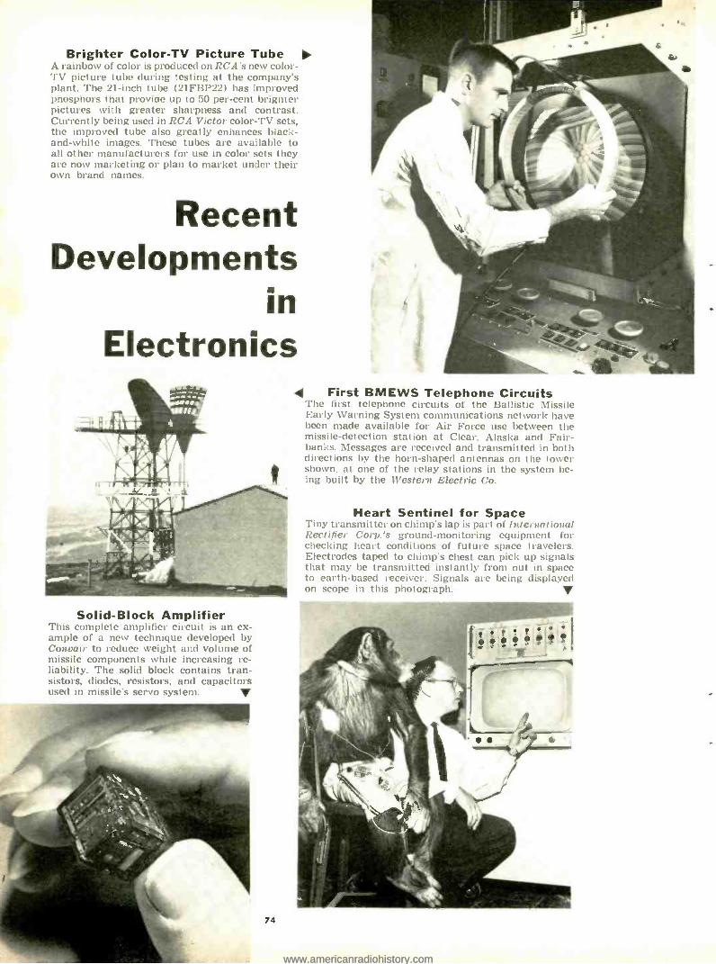
Brighter Color -TV Picture Tube A rainbow of color is produced on RCA's new color - TV picture tube during testing at the company's plant. The 21 -inch tube (21FBP22I has improved phosphors that provide up to 50 per -cent brighter pictures with greater sharpness and contrast. Currently being used in RCA Victor color -TV sets, the improved tube also greatly enhances black - and -white images. These tubes are available to all other manufacturers for use in color sets they are now marketing or plan to market under their own brand names.
Recent Developments
in Electronics
Solid -Block Amplifier This complete amplifier circuit is an ex- ample of a new technique developed by Convair to reduce weight and volume of missile components while increasing re- liability. The solid block contains tran- sistors, diodes, resistors, and capacitors used in missile's servo system. V
74
First BMEWS Telephone Circuits 'l'he first telephone circuits of the Ballistic Missile Early Warning System communications network have been made available for Air Force use between the missile -detection station at Clear, Alaska and Fair- banks. Messages are received and transmitted in both directions by the horn -shaped antennas on the tower shown. at one of the relay stations in the system be- ing built by the Western Electric Co.
Heart Sentinel for Space Tiny transmitter on chimp's lap is part nil Ioh-rnational Rectifier Corp.'s ground- monitoring equipment for checking heart conditions of future space travelers. Electrodes taped to chimp's chest can pick up signals that may be transmitted instantly from out in space to earth -based receiver. Signals are being displayed on scope in this photograph. V
www.americanradiohistory.comwww.americanradiohistory.com

Braid Carries Heart Pulses Human hearts that have stopped beat- ing can be started by sending timed electrical pulses to the heart through a thin stainless steel wire braid covered with plastic. The braided wire is at- tached to an electronic device - -the "Pacemaker" -that is worn around the patient's neck. The "Pacemaker" is transistorized and powered with mer- cury cells; it operates up to 40 days be- tween battery changes and its pulse rate is adjustable between 60 and 180 beats per minute. The braid, developed by National- Standard Co., consists of 16 stainless wires, each the thickness of a human hair. The steel braid (actually a catheter) is inserted through a vein at the neck, and thence into the heart. Sometimes the patient's heart regains enough strength to continue by itself after a week or two. One patient, how- ever, has carried the equipment for two years.
New "Dark- Heater" Tube The electronics technician in the photo is exam- ining two small heater wires in a laboratory dem- onstration of a new RCA chemical coating that greatly extends the life of radio and TV receiving tubes and also improves their performance. The "dark- heater" wire at the left, using the new coat- ing, has a 20 per -cent lower operating temperature than the bright -glowing conventional tube heater at the right. The company intends to use the new heaters in a wide variety of popular tubes intended for home radios, auto radios, TV sets, and phono- graphs. The new tubes are expected to last longer since there is less possibility of heater damage and shorts. In addition, the tubes are expected to have more stable characteristics, less a.c. leakage and hum, and a greater margin of safety in heater - cathode voltage ratings.
June, 1961
Outer -Space Radar Radar that uses a coherent light beam to detect distant targets has been developed by Hughes Aircraft Co. for use in orbiting satellites. The device marks the first practical ap- plication of the optical maser (or "laser"). Light from the laser trans- mitter (top) pulses out to a target, and is then reflected back and col- lected by the mirror in a telescope (below). Associated electronic equipment then amplifies and proc- esses the signal to provide range and distance data.
Electrically Suspended Gyro
First prototype of an electrically suspended gyroscope, developed by Minneapolis- Honeywell for use in the "Polaris" submarine navigation system, is being checked here. The gyro's rotor is suspended in a mag- netic field that is produced by ex- ternal coils to which high voltages are applied.
75
www.americanradiohistory.comwww.americanradiohistory.com

It is the belief of A. E. S. Inc., that we have de- veloped the high fidelity industry's first perform- ance duplicator, by this we mean, not just a unit to reproduce sound close to that of the real thing, but to give such a live performance that it would be considered not only reproduction but duplica- tion, to the point of temporary deliverance to the live performance.
This may seem to be quite an elaborate statement, but along with our own opinion we have in the past two years had many customers who have pur- chased our Gigolo speaker write in and tell us of comparison tests conducted in their homes with originally purchased speaker systems costing in many cases well over $100.00, these units consid- ered to be the industry's finest. Although their original system was a fine piece of reproducing
equipment it was still only reproduced sound, where in the case of their newly purchased Gigolo the sound seemed to be alive.
This remarkable performance plus the fact that we have sold in the past two years thousands of Gigolos, on a 100% GUARANTEE, cash return basis and have received only .5% (one half of one percent) returns, should prove that this is not just another advertising claim but a reality.
In the past, we have guaranteed the Gigolo to sound better than any bookshelf speaker manu- factured for home use on the market today re- gardless of price or your money back. We still make this offer and at the original price of $15.00 each. Please place your order now to insure rea- sonably prompt delivery.
1BU1K OWN
w WON anmxlee
r. eWMn naowe
YIi rillrreeleo enlala co. onlWll ]' WNW MIMI nrrvfqe [or
MUM nula Lou
NWn1Yn 1UMIMr1 all ((OIL
r Mr Ieseunl VOW.,
AM, ri COO eONllrll
The GIGOLO I is constructed with a resonant resistant wood product of at least ,/," thick- ness throughout. Its outside di- mensions are: 24" long, 12" high, 91/2" deep. The heavy construction and the fine work- manship suggest a value for exceeding its low, low price. All units sold on 100% money back Guarantee. Price $15.00. Unfinished Only, F.O.B. Factory.
The GIGOLO II is made of the finest select natural birch. All the wood used for the en- closure is at least s.L" thick. Outside dimen- sions are 24" long, 131/2" high, 12" deep. Our grill cloth is supplied by one of the country's largest manufacturers of acoustic grill material. Your GIGOLO II comes to you completely assembled and sanded ready for finishing in either blond, walnut, cherry, ma- hogany or ebony. All units sold on 100%
money back guarantee. Price -$49.50. Un- finished Only, F.O.B. Factory.
76 ELECTRONICS WORLD
www.americanradiohistory.comwww.americanradiohistory.com

AND NOW IN ANSWER TO TIIE QUES- TION OF SO MANY THRILLED GIGOLO OWNERS "IF THIS IS WHAT YOU CAN OFFER FOR 515.00 WHAT CAN BE DONE FOR A REASONABLE AMOUNT MORE ?" IN ANSWER TO TI IFS WE PRESENT TIIE GIGOLO II.
HERE IS A SYSTEM WITH TIIE ABIL- ITY TO REPRODUCE SUCH REALISTIC SOUND, HANDLE LARGE AMOUNTS OF POWER AND REPRODUCE SUCII EX-
TENDED FREO_UENCIES BOTH HIGI -I AND LOW THAT WE DO NOT RECOM- MEND IT FOR I TOME USE. A SYSTEM OF THIS TYPE WOULD MORE SUITABLY BE USED IN PROFESSIONAL APPLICA- TIONS, SUCII AS THEATRES, AUDITO- RIUMS, OR LABORATORIES, BUT FOR TIHHOSE WVIIO FEEL THEY MUST HAVE SOUND REPRODUCING EQUIPMENT BEYOND THE LIMITS OF HUMAN PER- CEPTION WE OFFER TIIE GIGOLO II FOR PUBLIC SALE.
SPECIAL NOTICE
All units purchased from A. E. S. Inc., either the recommended Gigolo I for home use, or the Professional Model Gigolo II, arc completely covered by our 100% MONEY BACK GUARANTEE. Upon receipt of your Gigolo, if you find any of the statements made in this advertisement were misleading or untrue, or if your Gigolo is not com- pletely satisfactory either in workmanship or performance, including reproducing frequencies and handling power beyond your requirements you may return this unit to the factory for full purchase price refund.
ORLON ACOUSTIC TERMINAL STRIP TO AMPLIFIER E OHMS DAMPENING MATERIAL
3/4" WOOD CONSTRUCTION REINFORCED ENCLOSURE
-
STANDING WAVE DISTORTION SHIELD
PNEUMATIC LOADING
MARIMUM CONTROL VOICE COIL 20% OF CONE DIAMETER
ULTRA -HIGH FREQUENCY HIGH PRESSURE VOICE WIDE ANGLE TWEETER COIL AIR RELEASE
10" HIGH COMPLIANCE WOOFER. ALMOST I" CONE DISPLACEMENT
SITCOM. REATES
ACOUSTICALLY TRANSPARENT GRILL CLOTH
EDGE
lune, 1961
A. E. S. Inc. 3338 Payne Ave., Cleveland 14, Ohio
Gentlemen please ship Gigolo I -$15.00 Each Gigolo 1I- $49.50 Each
I understand these units are guaranteed and if I am not satisfied I may return for a full purchase price refund.
Name
Address
City and State
Enclosed find check money order
77
www.americanradiohistory.comwww.americanradiohistory.com

ooooooooooooo O
KEEP CANDEE HANDEE: ó o
O RT91/ARC-2 TRANSCEIVER O
iiil,ornr: .\\I. , \t. li, ,1 1. 11 Inlnnl - 1 sIW rn,1. Ilange 111111 to nlln El' In Ight
O rha'nel,"lmmt'_'11í'I \Iñ.t.'
DC. /im.. bos..i39.95 . O 1 FAI MOUS O E'ER I I I O
This Is >IeueelÌalanlolokinR for111
J511 k, TI 59.95 o
:6C-ÌSJe 9.11 Me. 7 9 BC455: 0.11.1 Hc. 7 9
O MD-7 MODULATOR: SI,e,.11 39 O -
O A TRIO OF HEADSET BAROMAS, O HS23: 111 'nq,rl:mca. t.rnlbr 1,11.1.11.11 ;4.95 ne:11111am1. I11: I 11,n'. ,t In:\nnl,' O H3-33: Low In9a,lanr,.r'I.r: c- O rrd heHrin:Inn. Brand n . A',. ï. 5.95 ''' ndte . pealal O 141 Fl Headset: 15.0011 eyeles! Brand O iiew with chamois eunlurina. It's ter- 8.95 O CD-307Ä Headset Extension Cord: Ap 49,r O I,reiln:d,lr 5 fl. length. "n'y O APN -1 FM TRANSCEIVER
121,460 Me. e 11911. 01111 Haus, Ese. i.:6. 32.9 O .\pl,rox. .Im. sIt, per 111111 25 Ihn. TWO for 5.00
O YOU COT ITI WE WANT ITI LET'S DEALT We're paying top $SS for CRC -9: PRC -0, o -8. -9 -10: GN -3HA: All
`
electronic test equip. Weft, us ! estay! What Nave You?
O
O
O
O
O
T- 9e;ARC -S Nulle 2.1 -1 me. Earl. e' nd.. .54.9 T -19 -ARCS Nlnlr '1.1 ole Csrl. r 1.... 7.95 T- 20 /ARC5 Nmlr 4 -5.3 me. Esel. tond.... 4.9 T21 ARC -5 Stn, 5.9.7 ol. Esel. rond... .95
APX -S Conversion Manual .... 31.50
11! IrI:ot , Ii, ; ,i 11:11-! Blower...
Include' 3E29 'tube. I.n,í,i r59.95 rond.'. \1 STl -. \I. AT INI l' 1 + J Weight 40 ibs.
R -4A 'ARR -2 RECEIVER 2:1.123M `Ir. 11 1111,,'.. t nF'. liai` ,
O $2.95
O All items FOB Burbank, Calif., subject fo prior sole. In Coli). odd 4% Min. order $3.95.
o
t J. J. CANDEE CO. Dept. EW
o 509 No. Victory Blvd., Burbank, Calif. Phone: Victoria 9-2411
o
O
o
o
o
O
O
o
o
O
o
o
o
o
o
.o.o.o o.o1111 o o4Soooo
RADIO HANDBOOK - the comprehensive
reference source - a problem solver for
designers and builders of radio equipment
Gives simplified theory on practically every phase of radio. Tells how to design, build, and operate the latest standard types of radio transmitting and receiving equipment. More "How -To- Build" articles than any book in the field.
All information is original, up -to -date, and complete. 800 pages of data, clearly indexed, between hard covers -the largest RADIO HANDBOOK ever published.
*8.50
7$
-at your distributor a0fder tees yew tswrir NseaMk pub distritsla. If he cannot supply, send us his name and your remittance, and we will supply: foreign, add 10 %.
EDITORS and ENGINEERS, Ltd. Summerland 2. Cahlornla
Delos: Elestronic distribulels. arder from SOW , I,bruies. newsdeebrs order Iron Sabor S Tarlo,, Hillside. N. 1. r,porl lea. Canada /. from H. 1. Snyder Co . 440 Parli Ave Se.. N.Y. 16
Industrial Counting Techniques (Continued front page 41)
number of elements in each section. and the other channel controls the spacing between one section and the next. The long strip thus produced is later cut into individual sections. Each time the steel slug passes the pickup coil, cor- responding to the insertion of one metal element, a pulse feeds into the prede- termined counter. When the required number of elements has been inserted, channel A of the counter produces an output pulse. A solenoid now retracts the pawl from the ratchet, stopping the feed of metal. When the steel slug has passed the pickup coil a number of times corresponding to the desired spac-
STEEL SEGMENT
sl
BRASS DISC
MACHINE SHAFT
ELECTROMAGNETIC PICKUP COIL
DUAL PREDETERMINED ELECTRONIC COUNTER
CH AN.A- FASTENER LENGTH CHAN.B -SPACE LENGTH
= MACHINE
DRIVE
PUSH -PULL SOLENOIDS CONTROLLING METAL FEED
PAWL
RATCHET METAL FEED
Fig. 11. Use of a dual predetermined control to insert proper length of metal elements utilized in a slide fastener.
Fig
ing between sections, channel B pro- duces an output pulse. The pawl now engages the ratchet. and metal elements for the next section are inserted.
The "Programonitor" The "Cyclo- Monitor," manufactured
by Coe liter and Control Corporation, is a unique and versatile form of con- trolling counter. This unit consists of a rotating gear which moves axially on a threaded shaft. Segment cams attached to the front and back of the gear op- erate switches near each end of the gear travel. A mechanical clutch re- verses the gear rotation so that one counting cycle is completed during clockwise rotation and the next cycle during counterclockwise rotation. The count cycle can be preset to the desired number by means of calibrated dials, and units are available for stroke, rev- olutions. and electric (solenoid) count- ing. An expansion of this basic unit, the "Programonitor," is shown in Fig. 12. The prograni cylinder of this unit is a drum containing many holes arranged in a helical pattern. Pins inserted in selected holes operate Microswitches at predetermined counts during the com- plete counting cycle. Pins may be in- serted, for example. to produce switch- ing actions after 50, 125. 237, etc. pulses. Simply by changing the locations of the pins. a different switching program can be achieved. Units of this type are used industrially for controlling the pattern of holes punched in sound -dispersing tubes for automotive mufflers and for controlling the winding of stator coils for motors and alternators.
Conclusion
Industrial counting is no longer sim- ply a method of totalizing. but a form of automatic control. Such control has contributed significantly toward im- proved quality of product and reduced production costs. More important, per- haps, it has freed many workers from the tedium of routine tasks. allowing their talents to be utilized in more chal- lenging and productive areas. ---
12. Pins of program cylinder actuate switch after predetermined count.
ELECTRONICS WORLD
www.americanradiohistory.comwww.americanradiohistory.com

Microwave- Radiation Hazards (Continued from page 33)
however, problems of r.f. radiation measurement will not be entirely solved.
Problem of Effective Dosage
Even after we measure the radiation to which a subject has been exposed, the problem is only half solved. In the first place, not every subject is affected by radiation to the same extent. Frequency of the radiation is also an important factor. At some frequencies, people with thick layers of subcutaneous fat absorb radiation readily while at other fre- quencies the fat acts as a virtual insu- lator. Ultra -high frequencies pass through the body and can heat internal body tissues but layers of fat will ob- struct the radiation.
With microwaves the problem be- comes more difficult. Some of the micro- wave energy is reflected at the body surface -the amount of reflection de- pending on the body surfaces, the polar- ization of the energy, and the interven- ing medium between the generator and the subject. Microwave energy can be readily absorbed by the skin and fatty tissue directly beneath the skin and will not heat the body tissues underneath directly but as a result of stepped up circulation of the blood.
Thus, although the dielectric proper- ties of body tissues are well known and have been measured with some degree
of accuracy. we cannot predict the effects of radiation on an individual without knowing a great deal about his physical makeup. Moreover, when we must deal with the minute radiation in- volved in athermal effects. the problem becomes even more complex. One Dutch physician, W.A.G. van Everdingen, sought to eliminate this problem by in- serting, subcutaneously, small capsules of glycogen of precise concentration and viscosity.
The glycogen shows a rotation of its optical plane of polarization which can be measured with a polarimeter. This procedure is obviously unsuited to use with human subjects, although it did provide accurate dosage measurement for test animals.
Conclusion
Although we have reached a high level of sophistication in the radio and electronics fields, here is one problem which will plague scientists for some time to come -accurate radiation do- simetry for electromagnetic radiation in the u.h.f. and microwave regions. With space travel, enormous power levels will be required for communication and this will aggravate an already serious prob- lem, creating additional hazards for per- sonnel. Accurate personal dosimeters are expected to provide the answer.
In addition, new tools and approaches are needed to solve the major riddle of athermal effects which, although not considered dangerous to human life, will have to be re- evaluated in the light of future developments. -!3d-
)tl
illo
DID YOU FORGET To Send For Your Copy Of The 1961 "GREEN - SHEET " CATALOG? Don't fret. just use the handy coupon be- low to get your copy now.
Here are some specials:.. .
SO Foot, 8- Conductor Color -Coded Cable: Each lead is color -coded and tagged and num- bered. There are 8 spade lugs on each d Line is excellent and insulated with rubber covering. Each lead is individually covered with rubber also for added protection. so' Roll $2.95. RCA CRV -59AAC TV Camera: With 184c Iconosrops 595.00. Germanium Diode Sale: 1N34A, 1N60A, 1N69A I N70A Any ten for 1.00. Silicon Rectifiers: 750 Ma. Latest epoxy resin. bullet -type. subminiature rectifiers. 200 PIV
211e each l similar to 1N2069 i; 400 PIV re 32c each i similar to 1N207Oi: 600 PIV
re 36c each tsimilar to 1N2071 For the June Graduate: Beautiful World Globes Surface of the globes are raised -relief i actualls can feel mountains, etc. i . Ideal g :ft. $19.95. Sockets for 304TL and TH. New $1.15. C. D. Ham M Re . $110.00. Snooperscopes (see -in -the dark). Radius: 6' to 200'. Rand held. $59.00. RCA Precision 500 Et' crystal Oscillator: Accuracy plus or minus 0 0012'; . Contains precision 500 KC xtal. OMS Labs Xtal Oven. 5840 subm-min. tube. I term. ski. Mounts in standard 7 pin min socket. Requires 6.3 VAC or DC. 75 to 100 VDC with schematic. $3.73. Minimum order for above items -$3.00 Jennings UCS Variable Vacuum Capacitor: 10- 300 \ImF. o, 10 KV. Complete. i Less Shaft. i
$49.00. For 1991 Catalog ])nil coupon:
Barry Electronics Corp, 512 Broadway. NYC 12, NY Dept. EWS. Walker 5 -7000 Name Title Company A,I e
State
FANTASTIC VALUE...
with Squelch
DEALER INQUIRIES INVITED Radio -Phone is ideal for communication be- tween your boat and the shore, home, yacht club, or marina and provides dependable 2- way communications for construction crews, surveyors, farmers, hunters, fishermen and sportsmen of all kinds.
Famous "NAME BRAND" 27 m.c. "RADIO PHONE"
Citizens' Band 2 -way Radio
Single channel transceiver -27 megacycle citizens' band Versatile -can be operated by anyone, anywhere -on water or land May be used for personal con- versation not permitted on other frequencies 5 watt* transmitter with range up to several miles Highly sensitive receiver de- signed to hold ignition interfer- ence to a minimum Compact, portable -only 91/4" high, 71/4' wide, 5 " deep - weighs only 8 lbs.
GLOBE ELECTRONICS 3103 PICO BLVD., SANTA MONICA, CALIF.
EX 37206 -7
SPECIAL LIMITED OFFER!
Push -to -talk button on combina- tion microphone- speaker facili- tates one hand operation OFF -ON- VOLUME control 4 foot telescoping rod antenna may be completely detached Retractable carrying handle Attractively styled, weather- proof aluminum cabinet -two- tone blue with silver control panel Two types available for opera- tion from (1) 6 volt dc and 115 volts ac (2) 12 volt dc and 115 volt ac
$39Só 2 for $75.00
NO C.O.D. Orders Include sufficient postage for 104 or we will ship railway express collect.
June, 1961 79
www.americanradiohistory.comwww.americanradiohistory.com

Crò
TRANSMIT SELECTOR
u : s
II\ E
s i I. '
v e
o MICROPMONE
o Into Nno INTERNATIONAL CRYSTAL OAFS
MODEL 100 Available after June 15
VOLUME SQUELCH
111, 41111 OFF
TUNE
s CHANNEL
3 RL LIVE
SELECTOR
OPERATE CALIBRATE
RECEIVE TUNING
i MODEL 10 k omjro(
VOLUME
RECEIVE -TRANSMIT
Ç INTERNATIONAL CRYSTAL MFG.
TRANSMIT SELECTOR
80
MODEL 50 Available after April 15
VOLUMI 848118C14
MODEL 10
Available after June 15
AIL
ELECTRONICS WORLD
www.americanradiohistory.comwww.americanradiohistory.com

INTERNATIONAL'S
xecut i ve for S1'/1/;l1/llli f Wizen .ti band to iii in t, is ¡ct, t ¡on
INTRODUCING THREE SYSTEM - ENGINEERED TRANSCEIVERS
MODEL 100
The ultimate in Executive Citizens transceivers. NEW crystal filter which minimizes adjacent channel interference in the receiver. NEW built -in receiver calibration circuit. NEW International NR squelch. NEW 12 posi- tion crystal control transmit channel selector. NEW front panel microphone -
jack. NEW provision for connecting external speaker and S meter. Dual conversion superheterodyne receiver. Push -to -talk operation. Three way power supply for 6/12 vdc, 115 vac. Complete with 1 transmit crystal, 1 receive crystal, new style ceramic microphone and coil cord $199.50 *
MODEL 10
International's exciting NEW Compact transceiver for the budget minded customer who desires quality workmanship and engineering plus the best possible circuit for the money invested. Field tested full 5 watt transmitter contained in the higher price Executives. Tunable superheterodyne receiver covering all 23 channels. Three position crystal control transmit channel selector. Manual transmit -receive control. Noise limiter. Available acces- sories include four separate power supplies - 6 vdc, 12 vdc, 24 vdc or 115 vac, push -to -talk relay kit, squelch kit, and 12 position transmit channel selector. Complete with 1 transmit crystal, matching microphone and external speaker, but less power supply $59.50 *
MODEL 50
A precision engineered transceiver featuring push -to -talk operation. Three position crystal control transmit channel selector. Dual conversion super- heterodyne receiver tuning all 23 channels. Series Gated automatic noise limiter. NEW International NR squelch. Three way power supply - 6/12 vdc, 115 vac. Additional features of Model 100 are available as accessories, and may be added at any time. Complete with 1 transmit crystal, matching microphone $149.50
*Suggested Price
SEE THE EXECUTIVE SERIES AT YOUR AUTHORIZED INTERNATIONAL DEALER
INTERNATIONAL CRYSTAL MANUFACTURING CO., INC. 18 NORTH LEE OKLAHOMA CITY, OKLAHOMA
June, 1961 81
www.americanradiohistory.comwww.americanradiohistory.com

improve reception
with s WONDER OD
G r o u n d P l a n e
ANTENNA
for base station transmitters operating between 25 & 88 MC's Sturdy fiberglass sheath encasing conductor le- ments of this base station antenna reduces pre-
cipitation static and dampens vibrations. Excep-
tional strength results from the special Shakespeare
construction that distinguishes all WONDEOD an- tennas. Non -directional, vertically polarised - drooping radials for broad band operation. High - strength white fiberglass sheath, cadmium plated steel support brack- - et for mounting on srm n.. e-wie I1 /c pipe thread.
SO -239 UHF con -
nection.
539.95
lava. 0.11
61.0
61.1
61.2
163% F %
113'h 99'h
144% 77K
77.t on« C1 23.30 no«
30.33 roc
61.3 131 74 33.40 am
61 -4
613 61.6
61.7
131 63
103% 3311
93% 30
69% 37%
40.0 mc
47.34 no«
34.72 ac
72.11 ,nc
*Unless fr er specif ied en erd.r, w. will furnish cutting far
curves
atng antenna omfre- u Po ra peensin within MOWN. iwi its band.
P COLUMBIA PRODUCTS co. Subsidiary of Shakespeare Company
Columbia. South Carolina
LEARN TRANSISTOR, COMPUTER OR
RADAR ELECTRONICS
AT HOME !
Prepare now for a profitable career in one of these growing fields. Learn theory and practical application of all makes and types with proven home study courses from the Philco Technological Center. For FREE information write:
PHILCO, TECHNOLOGICAL CENTER P.O. Box 4730, Dept. W -2. Philadelphia 34. co
82
"SEMICONDUCTORS AND TRANSISTORS" edited by Alexander Schure. Published by John F. Rider Publisher, Inc.. New York. 135 pages. Price $2.90. Soft cover.
A discussion and evaluation of theory and characteristics of semiconductors and transistors with specific attention being given to atomic structure, quan- tum theory, conductors, insulators, and semiconductors. Conduction by holes, semiconductors with impurities. and the semiconductor rectifier are analyzed along with characteristics of p -n and a -p types.
Review questions are included at the end of each chapter.
"101 KEY TROUBLESHOOTING WAVEFORMS FOR VERTICAL -SWEEP CIRCUITS" by Rob- ert G. Middleton. Published by Howard W. Sams d Co.. Inc.. Indianapolis. 121 pages. Price $2.00. Soft cover.
This is the third in this author's cur- rent series dealing with scope wave- forms as an aid to TV troubleshooting. This volume covers the four types of vertical- oscillator and vertical- output stages. Along with photos of 101 abnor- mal waveforms, the author provides de- scriptions of circuit symptoms, evalua- tion tests. and notes. A comparison he- tween the set on the test bench and the scope patterns included in the text can reduce service time and eliminate costly guesswork.
a a o
"CITIZENS BAND RADIO HANDBOOK" by David E. Hicks. Published by Howard W. Sams d Co.. Inc.. Indianapolis. 187 pages. Price $2.95. Soft cover.
This practical guide covers choosing equipment. getting a license. and dis- cusses CB equipment circuits. antenna systems, fixed and mobile station instal- lations, maintenance and repairs, serv- icing adjustments and measurements. as well as operating procedures.
A glossary of CB terminology and an appendix containing the latest FCC CB Rules and Regulations are also included.
a o ..
"ALTERNATING CURRENT ELECTRICITY" by Alexander Efron. Published by John F. Rider Publisher. Inc,. New York. 93 pages. Price $2.25. Soft cover.
A basic text on alternating current which would be entirely suitable for the beginning student or the student tack- ling the subject on his own. The text is clear, well -written, and progressive with every chapter including problems of graded difficulty as well as questions and problems for self- testing.
o C
"TV TROUBLE ANALYSIS" by Harry Mileaf. Published by Cernsback Library. Inc.,
New York. 220 pages. Price $3.20. Soft cover.
This volume demonstrates in a prac- tical fashion how and why components and circuits fail and how these failures affect the audio and video sections of a TV receiver. By familiarizing himself with the theory and operation of a re- ceiver in trouble, the technician can improve his practical performance by cutting down on servicing time and in- creasing his ability to pinpoint troubles on unfamiliar sets.
"ABC'S OF RADAR" by Alan Andrews. Published by Howard W. Sates cf Co., hie- Indianapolis. 112 pages. Price $1.95. Soft cover.
To judge by our correspondence there is considerable interest in the subject of radar but unfortunately not too many texts at a basic level are currently avail- able. This volume should close this gap for technicians. students. and users. The text covers how radar works. types of systems, microwave principles, antenna systems, receivers and indicators, tuners and modulators, in addition to material needed in studying for the FCC Radar Endorsement Examination.
a e o
"SERVICING AGC SYSTEMS" by Henry Carter & Thomas Lesh. Published by Howard W. Scans d Co.. Inc.. Indianap- olis. 121 pages. Price $2.00. Revised edi- tion. Soft cover.
This is a completely revised edition of an earlier work and now embraces a.g.c. circuit theory for every type of system in use -including the modern BU8 variations. Nine chapters cover t he a.g.c. systems in various forms from their correct functioning to a.g.c. in trouble. The text includes line drawings. partial schematics. and CRT screen photos.
a
"RADIO AND TV TROUBLE CLUES" by Sams Staff. Published by Howard W. Sams d Co., Inc., Indianapolis. 96 pages. Price $1.50. Soft cover.
This practical handbook for the serv- ice technician is based on actual experi- ences of running down and curing "tough dogs." The first two chapters cover locating troubles while the third section includes a series of unusual trou- bles and their solutions. The text is lav- ishly illustrated with photos, schemat- ics. and line drawings.
a
"1960 -1961 TV CIRCUIT HANDBOOK" by Samuel L. Marshall. Published by How- ard W. Sates d Co., Inc., Indianapolis. 135 pages. Price $3.95. Soft cover.
This volume is intended to serve as
ELECTRONICS WORLD
www.americanradiohistory.comwww.americanradiohistory.com

Complete Portable Communications for Everyone
9 CITIZENS BAND
ttWALKIE TALKIE"
Ship to
Shore
For
Farming
LAFAYETTE
Construction Work
NO LICENSES,
TESTS OR
AGE LIMITS
-TRANSISTOR
H E-29
LAFAYETTE HE-20A
Deluxe CITIZENS
BAND TRANSCEIVER
Complete with Leathe Carrying Case, Earphone.
Antenna, Batteries, and Crystal
ONLY
95 10 Down 5A0
Now With Added Deluxe Features- Pi- Network for Greater Power Output Calibrated "S" Meter 14 Tube Performance, 3 Diodes Built -in 12 Volt Power Supply
for Mobile Use Complete with Matched Crystals for Channel 9
Completely Wired -Ready to Operate Fully Transistorized -9 Transistors plus 1 Diode Uses Inexpensive Penlight Batteries No License, Tests or
Age Limits Comes with Leather Carrying Case, Earphone, An- tenna, Batteries and Crystals As simple and easy to use as the telephone -and twice as handy. Receives and transmits up to 7 miles under favorable conditions, or 1.5 miles under average conditions. Weighs only 18 -oz. and slips into your pocket. Push-to- talk button operates built -in speaker as sensitive microphone.
MADE IN U.S.A.
A highly efficient 2 -way communications system operating over a distance of up to 20 miles or more depending on terrain. Features 4 crystal -controlled transmit positions and 4 crystal -controlled receive positions. Tuneable superhet receiver covers all 23 assigned channels. Other highlights include dependable push -to -talk ceramic mike & relay, adjustable squelch control, automatic series gate noise limiter and illuminated dial.
H E-800WX
LAFAYETTE HE-15A
SUPERHET Citizens Band TRANSCEIVER Completely Wired -Not A Kit 5 Crystal- Controlled Transmitting Positions Tuneable Receiver Over Full 23 Channels High Output Crystal
Microphone Complete with Transmitting Crystal for Channel 9
A compact, precision transmitter and receiver covering up to a 20 mile or more radius, depending upon conditions. The HE -15A features an effective full -wave variable noise limiter, RF jack on front panel, planetary vernier tuning, 5 -prong microphone jack for easy relay ad- dition, and 12 tube performance from 4 dual -function tubes, 2 single - function tubes, 2 rectifiers.
HE -19 Telescoping Whip Antenna Net 3.95 HE -16 Power Supply for 12 Volts Net 10.95 HE -18 Power Supply for 6 volts _. Net 10.95
ONY 50 5
5.00 Do wn
MADE IN U.S.A.
LAFAYETTE ALL -IN -ONE CITIZENS BAND MOBILE ANTENNA
The Scoop Buy for Citizens Band Mobiles
Chrome Swivel Base Stainless Steel Spring 1021/2'ß Stainless Steel Whip for Optimum 11 -Meter Performance
Chrome swivel ball mount base designed for mount- ing on any surface. Stainless steel spring holds rod in properly adjusted position and prevents rod dam- age from shocks and blows. Stainless steel whip for maximum resiliency and strength. FAYETTE
1k_ D = 0 165.08 LIBERTY AVENUE, JAMAICA 33, N.Y. OTHER LOCATIONS
NEW! LAFAYETTE RADIO FIELD INDICATOR T Continuously Indicates Transmitter Output TM -14 Rugged 200 ua Meter Movement Requires No Electricity, Batteries or A Must Transmitter Connection
Check the performance of marine, mobile or fixed transmitter. Features a 200 ua meter movement with vari- able sensitivity control. Earphones can be plugged in for an aural check of output. Antenna extends from 31/4" to 102/4 ". Magnet on bottom plate allows easy mounting on car 6.95 dash or metal surfaces. Size, less antenna, 348W, 2114H, 2 "D.
for All Ham
and CB
Operators
PLEASE INCLUDE SHIPPING CHARGES WITH ORDER
NEW YORK, N.Y. NEWARK, N. J. BRONX, N.Y. PARAMUS, N.J. BOSTON, MASS. PLAINFIELD, N.J.
100 6th Avenue 24 Central Avenue 542 E. Fordham Rd. 182 Route 17 110 Federal Street 139 W. 2nd Street
www.americanradiohistory.comwww.americanradiohistory.com

FREE CAREER
BOOKLET
to guide you to a successful future in
ELECTRONICS RADIO -T COMPUTERS ELECTRICAL ENGINEERING This interesting pictorial booklet tells you how you can prepare for a dynamic career as an Electrical En- gineer or Engineering Technician in many exciting, growing fields: MISSILES RADAR RESEARCH ELECTRICAL POWER ROCKETRY
AUTOMATION AVIONICS SALES DEVELOPMENT
Get all the facts about job opportu- nities, length of study, courses offered, degrees you can earn, scholarships, part-time work - as well as pictures of the Milwaukee School of Engineering's educational and recreational facilities. No obli- gation - it's yours free.
MILWAUKEE SCHOOL OF ENGINEERING
MAIL COUPON TODAY! MILWAUKEE SCHOOL OF ENGINEERING Dept. EW -661, 1025 N. Milwaukee St. Milwaukee, W' nn in MS -113
Please send FREE "Your Career" booklet I'm interested in Electronics Radio -TV
Computers Electrical Engineering Mechanical Engineering
(PLEASE PRINT)
Name ........__.___
Address.
City Zone ........_.State .._..._ _.... _..
I'm eligible fl,r. eteranv education benefits. Discharge date
IL J
84
a one -source reference to all new cir- cuits used in 1961 TV receivers. Thir- teen chapters cover circuits used by all the major manufacturers -from re- mote -tuner controls to picture tubes and including the latest in color TV.
The receivers of twenty -one manufac- turers have been included along with troubleshooting data, schematics, and block diagrams of the units being dis- cussed.
e e e
"BASIC MATHEMATICS" by Norman H. Crowhurst. Published by John F. Rider Publisher, Inc., New York. 141 pages. Price $3.90. Soft cover. Vol. 1.
This is the first of a projected four - volume series which is designed to cover the field of mathematics progressively. This first book deals with arithmetic as an outgrowth of learning to count with counting, addition, subtraction, multi- plication, division, fractions, decimals, percentages, and graphs covered.
If your basic grasp of some of the fundamental operations of mathematics is shaky, here is the place to start-
with arithmetic. Heavy use is made of illustrative material.
..
"BASIC TRANSISTORS" by Alexander Schure. Published by John F. Rider Pub- lisher, Inc., New York. 142 pages. Price $3.95. Soft cover.
This is a comprehensive, but basic, approach to the subject of transistors. The lavish use of schematics, photo - diagrams, line drawings, and cartoon illustrations help to convey the content. Review questions are included at the end of each section to aid the reader in determining his grasp of the ma- terial.
e e
"AN INTRODUCTION TO ELECTROTECH- NOLOGY" by S. J. Kowalski. Published by John F. Rider Publisher, Inc., New York. 294 pages. Price $7.00.
This text covers a.c. and d.c. electric- ity at a college level with considerable emphasis on the mathematical aspects. Those seeking a rigorous treatment of the subject and with sufficient mathe- matical background should find this
Single -Turn Coil Adjustment By HOWARD S. PYLE, W70E
HERE'S one that has apparently "gone by the board." Both radio hams and
commercial builders have used the stunt to be described for many years as an easy method of obtaining single -turn adjustment of an inductance by means of switching. It is still a good trick and well worth using.
Suppose, for example, that you have a 37 -turn airwound inductor which you want to adjust, a turn at a time, for use in an antenna tuner -maybe a base - loading coil for a vertical antenna or some similar application. You have trou- ble getting an alligator clip or equiva- lent on the turn you want, without shorting out adjacent turns. Further- more, if the coil is mounted in a metal housing, as is customary with antenna tuners and such devices, you find that despite all your care, including a "seat of the pants" compensation calculation, the adjustment doesn't hold when you put the cover plate back on the cabinet.
Wouldn't it be nice to simply turn a knob on a rotary switch and pick your turn? You can: you don't need a 37- point switch for a 37 -turn coil, nor a 50 -point switch for 50 turns. For the 37 -turn coil shown in Fig. 1, two 7 -point rotary switches will do the trick. For 50 turns, two 10 -point switches; for a
Fig. 1
TAP EVERY FIFTH TURN
111111 IIIII'I1111111111111111111111
TAP EVERY TURN FOR SEVEN TURNS
I TO CIRCUIT
iJ
NOTE: WITH SWITCHES IN POSITION SHOWN 12 URNS ARE IN THE CIRCUIT AND ALL UNUSED TURNS ARE SHORTED OUT
30 -turn coil, use two 5 -point switches. From the example shown in Fig. 1, you can figure out the correct switch for about any size coil which the ham would ordinarily use.
And, to make it easier to solder your taps to the coil turns, particularly on fairly closewound coils, use the stunt illustrated in Fig. 2. Merely push down the adjacent turn each side of the one you want to tap, using a small screw- driver or similar tool. For the single - turn taps which connect to S_ in Fig. 1, stagger these "push- downs" around the coil, as shown in Fig. 2.
This single -turn coil adjustment method is ideal for the conventional coil stock made by many manufacturers. It will also work well on your home -built coils whether spacewound of bare wire or closewound of insulated wire. -l-
Fig. 2
FACTORY- SUPPLIED ONE TURN BENT PLASTIC SPACERS DOWN ON EACH
SIDE OF TAP POINT SOLDERED
TAP
IA1
METHOD FOR TAPPING EVERY SEVERAL TURNS, 5,5,10 ANO SO ON,TO CONNECT TO SUFIS.II
FOR THE SINGLE -TURN TAP PORTION OF THE COIL, STAG- GER YOUR ADJACENT BENT - DOWN TURNS AROUND THE CIRCUMFERENCE THUS
ELECTRONICS WORLD
www.americanradiohistory.comwww.americanradiohistory.com

book useful. Practical examples and worked -out numerical presentations make this volume suitable for home - study providing the abovementioned prerequisites are met.
* a
"MOST- OFTEN -NEEDED 1961 RADIO DIA- GRAMS AND SERVICING INFORMATION" compiled by M. N. Reitman. Published by Supreme Publications, Highland Park, III. 190 pages. Price $2.50. Soft cover.
This is Volume 21 in this publisher's radio series and like its predecessors provides schematic diagrams, printed circuit views, all alignment and other service details needed to handle 1961 model radios, including auto sets, tran- sistor portables, AM -FM combinations, stereo, etc.
Twenty -nine set makers are repre- sented in this volume.
o
"ELECTRICAL PRINCIPLES OF ELECTRONICS" by Angelo C. Gillie. Published by McGraw -Hill Book Company, Inc., 517 pages. Price $10.00.
This is a basic text for the radio -TV service technician, the electrician, the layman, and the student. It provides clear, precise explanations of the funda- mental laws and principles of electricity and describes the new techniques and devices currently used by the electrical and electronics industry.
Since mathematics is used extensively throughout the text, including test prob- lems at the end of each chapter, the
reader is warned to sharpen his mathe- matical skills before tackling this book.
a *
"PRACTICAL AUTO RADIO SERVICE 8 IN- STALLATION" by Jack Greenfield. Pub- lished by Gernsback Library, Inc., New York. 156 pages. Price $2.95. Soft cover.
Not only does this volume tell how to get the radio into or out of the car but it describes in detail the different types of sets, the equipment and compo- nents needed to set up an auto radio servicing shop, how to remove and in- stall rear -seat speakers, how to trouble- shoot and repair all types of auto radios in addition to tuners, power, interfer- ence suppression, FM, and auto phono- graphs. The text is copiously illustrated.
o o e
"R /C PRIMER" by Howard G. McEntee. Published by Kalmbach Publishing Co., Milwaukee. 66 pages. Price $2.00. Soft cover.
This book tells how to install and op- erate radio -control equipment in planes, boats, and other models. Nine chapters cover frequency and licensing informa- tion, control with various types of equip- ment, components, transmitters, instal- lation, model boats, field and installation tests, maintenance, and troubleshooting. The text is detailed and well illustrated but is based on commercial equipment rather than "build -it- yourself" gear.
a a
"JONES NORTH AMERICAN AM -FM RADIO -TV STATION LISTINGS" compiled and published by Vane A. Jones Co., 3749 N.
Keystone Ave., Indianapolis 18. 90 pages. Price $1.00. Soft cover. Vol. 3.
This is an updated listing of over 7000 stations operating in the U.S. and Pos- sessions, Canada, Cuba, Mexico, and the West Indies. The booklet lists stations by location, frequency, and call letters.
o e no
"TUBE SUBSTITUTION HANDBOOK" by Sams Staff. Published by Howard W. Salas d Co., Inc., Indianapolis. 96 pages. Price $1.50. Soft cover. Vol. 2.
This is a revised and up -to -date listing of tube substitutions and covers over 4450 recommended substitutes.
The directory of receiving tubes has been expanded to 1644 types while three additional sections list 186 industrial and 494 European substitutes for Amer- ican receiving types and 453 American receiving -tube substitutions for Euro- pean types.
a a o
"SECOND -CLASS RADIOTELEPHONE LI- CENSE HANDBOOK" by Edward M. Noll. Published by Howard W. Sams d Co.. Inc., Indianapolis. 240 pages. Price $3.95. Soft cover.
This is a basic text covering all the information needed to pass the FCC's second -class radiotelephone license exam (which is required of anyone who services and some who operate two -way mobile radio equipment).
There are six chapters of questions and answers covering Elements I, II, and III. The 650 questions are arranged progressively. -[
"More than Citizens' Radio "... a complete, fully engineered "industrial- type" transceiver!
Anyone can operate -license issued by the FCC on request from $13495
Complete 23 channel Citizens' Band coverage -choose 1 of any 5 channels by the flip of a switch. Maximum legal power -excellent range -meets all FCC requirements. Excellent receiver sensitivity and selectivity -full fidelity voice reproduction.
"More than just 2 -way Citizens' Radio equipment" -the Viking "Messenger" will deliver the finest performance of any equipment available in the field. Designed throughout for 10
watt power level- limited to 5 watts for Citizens' Radio. Easy to install anywhere in your home, business location, car, truck or boat ... offers many unique features found only on
more expensive communications systems. Built -in Squelch, Automatic Volume Control, and Automatic Noise Limiter. Compact, modern styling -only 5 Ye" high, 7" wide, and 11 s/e"
deep. Complete with tubes, push -to -talk microphone, and crystals for one channel.
c FREE ' - Color Brochure
° ale ..
t'\ LW ,. Wit"
Farming. Boat -to-boat or Your own Construction or delivery or ship -to -shore personal or "off-the- road" fleet operation communication family use equipment WRITE TODAY
June, 1961
JE.F.JOHNSON COMPANY JJ 2510 10th Ave. S W. Wasem, Minnesota
Please rush me your full color brochure describ- ing the Viking "Messenger" Citizens' Transceiver.
NAME
ADDRESS
CITY STATE-.-__
Manufacturers of the world's most widely used personal communications transmitters
85
www.americanradiohistory.comwww.americanradiohistory.com

A new arrival in a community usually keeps dealing with the first service shop he uses. Make sure it is yours.
By ERNEST W. FAIR
Qai iv. qpisii
WHEN A new resident establishes himself in a neighborhood, he sel- dom has had any previous contacts
with local merchants. including service dealers. When he needs their services, he may ask a neighbor's advice or try one at random. In any case, as long as he gets reasonable satisfaction, he is likely to stay with the first contact he has made in each area for an indefinite period. This rule applies to his choice of an electronic service dealer as much as to any other type.
It follows that an extra effort to land such a customer is well worth making, even though it may not be easy. A few such newcomers will wander into your shop on a strictly random basis -if no competitor is doing anything to get them himself. However, if you belong to the majority of dealers who are looking for more business, why settle for this handful?
How do you get these new clients? Your regular advertising and promotion techniques for stirring up new business are probably not good enough, because they may not have the right approach for the special situation and because they seldom will be timed right. Re- member, for example, that most people who have just moved have good reason to be in the market for service soon. Their TV sets may have acquired mal- functions in the process of moving. An antenna installation may be an im- mediate requirement. Perhaps there is a need to re- install and adjust a hi -fi system. You've won at least half the battle if you have reached them before they have had a chance to look for any- one. Your special methods must be built around two important points: getting their names and addresses quickly and then making fast contact.
There are some excellent sources for getting the names. High up in this cate- gory are the offices of local public -utility companies. To make certain they have gas, electricity, and a phone available by the time they move into their new homes, people generally make arrange- ments in advance. You can be waiting at the newcomer's door before he gets there! Although the utility companies have no reason for going out of their way for you (i.e., you can't expect them to mail you all new names automatical- ly), they may let you check directly at their offices. To get names early, check as often as possible. Once a week is a good idea, if you can manage it. In some cities, such lists are published in busi- ness and legal newspapers.
Another good source is made up of local real -estate people, including build-
86
*LOCAL
POWER.
ers. These are worth trying because the names may be had well in advance of most moves and because the proportion of home buyers is high. The latter types are more likely to be in the market for new sets and other equipment or new installations.
Newspaper- delivery boys should also be considered. Although they cannot provide the most complete or earliest lists, their cooperation should be easier and cheaper to get if you run into trouble with other sources. An offer of, say, twenty -five cents for each new name should settle the matter.
Chambers of Commerce often make up such lists for their members. The only drawback is that your competitors may be members of the same group. If they are also making use of this source, you are better off with one of the agen- cies that can give you the names more quickly.
Some shop owners work together with local owners of other small businesses in exchanging newcomer names. The usual procedure is to cooperate with a few carefully selected firms, none of which is in competition with any other. Grocers, druggists, and service stations are among the better candidates. You will need other sources so that you can have names to exchange, but these fel- low dealers may give you names that have not turned up in other ways.
Your old customers can often be help- ful in tipping you off on new people coming into the community. Getting ac- tive, continued cooperation is difficult
/
without organizing a special program that would probably include some re- ward, but it doesn't cost a thing to drop a conversational question about any- thing new in the neighborhood -like new faces -every time you deal with a regular customer. You may catch a pros- pect or two that has slipped by other dragnets.
Finally, check the social or "society" section of local newspapers. Churches and other organized groups often give welcoming parties to recent arrivals, and these affairs will be listed. You will note that the strongest potential sources have been listed first. Neverthe- less. local conditions may make a pre- ferred source difficult to use or change the order of value. In any case, all of the suggestions have some merit.
Now let's assume that you reliably have the names of new people coming in. You still have to decide what to do with them. Even if your competitors have not been shrewd enough to acquire such lists as actively and successfully as you have done, it pays to do a good job of making contact. If your competitors are man- aging to keep up in the matter of getting names, the way in which you handle prospects is even more important.
A personal call is always the best type of contact. Try to make one early and try to make it yourself. However, if you are too busy, you may be able to dele- gate the chore to someone else, prefer- ably a member of your shop staff who is likely to make a good impression. Mailed appeals are certainly useful and should
ELECTRONICS WORLD
www.americanradiohistory.comwww.americanradiohistory.com

from each type of business, they have a special value. They are worth the fee they charge partly on the ground that they will not accept your competitors if you join up with them first.
For all the importance given here to some form of personal contact, the need for other supporting techniques, mostly involving the printed word, cannot be eliminated. Some printed matter can and should be brought along, as already noted, even on the personal call.
The most productive type of promo- tion item is one that, in addition to carrying your message, has some other value to the customer so that he will keep it and use it. Many business firms offer maps of their city or area. Espe- cially useful to the new arrival until he can find his way about the strange com- munity, these maps are most practical to obtain in quantity in a growing area that sees a reasonable rate of newcom- ers. To defray costs, they can be worked out cooperatively to carry the messages of a few other, non -competitive mer- chants.
A window sign or similar poster spe- cifically directed to this type of cus- tomer is also helpful. One approach used begins, "Newcomer to the community?
not be overlooked. However, in an active community, a recent arrival may get so many of these that he doesn't pay much attention to any. The personal call is successful because it is flattering. Any printed matter you might ordinarily mail can be taken along and handed over to the prospect directly.
Where conditions rule out the practi- cality of direct visits, the telephone may be your next best weapon. It retains the advantage of permitting a contact that is personal and flattering. It also in- volves little time, effort, or expense. Per- haps you can arouse the prospect's curi- osity enough so that he will act on your invitation to drop into your shop for a look around when he is nearby, even if he has no particular work in mind.
The "Welcome Wagon," a relatively new development, is also a good substi- tute for your personal visit. Such enter- prises usually exist in the more active communities -the very ones where it may be difficult for you to make per- sonal calls yourself. These projects gen- erally use well trained hostesses to call on the newcomers, present them with gifts, and apprise them of the services available from those local firms which the enterprise represents. Since these "wagon" enterprises, whatever titles they may use in various parts of the country, accept only one subscriber
June, 1961
(ì a;7 nr rr ,/,
' e
Come in and get acquainted." You can 1 work out your own message. If you are offering a map or other introductory gift as an inducement, this sign is the place to mention it. As to good locations for such signs, this is something you will have to work out yourself, because there are so many local variables. It is hard to anticipate in general what locations are most likely to catch newcomers or where you will have least difficulty in getting permission to place the posters. Don't overlook your own shop window, especially if you are well located. It costs nothing.
Advertising in such places as hotels and motels also should not be over- looked. People who are going to settle in a new community often make their first contacts there at just such estab- lishments : they frequently stop at one of these while seeking new homes or making arrangements for their moves.
Finally don't neglect an old standby - t he Yellow Pages of the phone directory. When a specific item or service is needed in a hurry, a person without prior contacts is more likely to use this source than a regular resident. However your ad here should be prepared to carry a word or two of welcome to new neighbors. This may guide such people to choose your listing from a handful of similar advertisers.
Although some of the suggestions made here have been shown, on the aver- age, to be more effective than others. there are no fixed rules. Local condi- tions can make averages meaningless. The resourceful shop owner will be ready to experiment, as he must in all things. If he makes the effort, he is al- most certain to come up with a profit- able program that outweighs its cost.
I 87
I
I
I
I
I
I
i r
www.americanradiohistory.comwww.americanradiohistory.com

from ELECTRONICS
BOOK SERVICE
books on radio & tv servicing ... yours for a
7,-DAY FREE
Here is a comprehensive selec- tion of books covering the field of radio and television servicing -for your use and profit! You'll find practical guides, reference books, background and advanced texts to give you step -by -step procedures for finding troubles and repairing radio receivers, television and FM sets, setting up your own servicing business, designing and building, and much more -each book filled with descriptive illustrations and.' diagrams.
And you can have one or more of these top notch best sellers - for 7 days FREE!
Simply write your choices on the coupon below and mail it to- day. Read and enjoy your books '
for seven full days. If, after that time, you do not agree that they ,
are everything you want, return them and owe nothing. Otherwise, '
send along your payment of our bill plus a small charge for postage ,
and handling. Here is the perfect way for:
every serviceman to build the li- ,
brary he must have. Order now!
2404. FM RADIO SERVICING HANDBOOK, King This is a practical guide to frequency - modulated V.H.F. ra- dio receivers, their design, construction, alignment and re- pair. Includes chap- ters on adaptors,
aerials, and high -fidelity audio equipment. A good introduction to FM theory, kept as non -math- ematical as possible. $5.00 2410. TELEVISION AND RADIO REPAIRING, Markus This book shows how to test, repair and replace each com- ponent of TV and radio receivers, power supplies, resistors and condensers, coils, tuning de- vices, and speakers. Shows what servicing involves, how to get information and tools necessary. The book includes the T.V. De- tect -0- Scope. $7.95
2422. HANDBOOK OF TV REPAIR, Hertzberg The simple mechan- ical and electrical maladies which are the great majority of television set troubles - what you
can do about them and what not to try. Covers tubes and testing, antennas, UGH convert- ers, fringe -area reception, the set and the chassis. $2.50 2506. FUNDAMENTALS OF RADIO AND ELECTRONICS, Everitt, et al All you need to know on elec- tronics and radios is found in this book -including transistors and vacuum tube principles and circuits. A product of close col- laboration among five radio au- thorities, it is perfect for self - study. 832 pp. $11.35 2402. PRACTICAL RADIO SERVICING, Marcus and Levy Dealing with the common types of radios in use, a -c /d -c re- ceivers, phonograph players. and battery and three way portables. This book not only describes cir- cuit fundamentals and servicing instruments and methods, but also gives graded job sheets giving valuable practical experi- ence. Includes the indispensable Radio Detect -O- Scope. Illus- trated. $8.95 2403. ELEMENTS OF RADIO SERVICING, Marcus and Levy Gives practical, step -by -step pro- cedures for finding troubles in radio receivers and making re- pairs. Readers with a background of simple radio theory can easily understand the book. Emphasizes over -all servicing procedures. $7.25 2406. ESSENTIALS OF TELEVISION, Slurzberg, Osterheld and Voegtlin Comprehensive study of basic TV circuits. The operation of a color set and three monochrome receivers is described in detail from the antenna to the picture tube and loudspeaker. Features the sound section, waveforms, the picture tube, etc. Complete with illustrations, examples. questions, problems. $8.95
2409. TELEVISION FOR RADIOMEN, NoII Here are the principles and es- sential mathematics of televi- sion. Detailed studies of cascade tuners, new video amplifier techniques, large screen pic- ture tubes, modern deflection systems, latest antenna detail. Covers U.H.F., color TV, tran- sistors, some topics not dealt with before. Construction, oper- ation and servicing of television. $10.00
2411.TELEVISION SERVICING, Levy and Frankel Explains how to find the section in which the trouble occurs and then to find the defective compo- nent. From the cir- cuits discussed,
which are employed in over 95% of TV receivers now in use, the reader gains an understanding of the principles involved. A knowledge of basic electronics is essential. $7.75 2423. BE YOUR OWN TELEVISION REPAIRMAN, Guth Seventy -five percent of the time the only trouble with your TV set is a faulty tube. With this complete book, covering all man- ufacturers' models, you can eas- ily replace the tube yourself. One dollar saves big repair charges. $1.00 ---- 2804. RADIO AND
TELEVISION MATHEMATICS, Fischer Whenever you need to look up the use of a formula or the correct substitution of numbers, you can
find it here -rapidly. More than 700 step -by -step solutions of the usual problems encountered in radio, television and industrial electronics, including all those needed for FCC exams. $6.95 2419. BASIC TELEVISION, Grob The basic book for training tele- vision servicemen and techni- cians. No mathematics other than simple arithmetic and alge- bra is needed. 660 pages with illustrations. $9.25 2420. TELEVISION FUNDAMENTALS, Fowler and Lippert A simple nonmathematical pres- entation of the basic principles the radiotechnician must know in order to install and service television receivers. Sound treat- ment of each element of the system -from the antenna to the picture tube. $8.50 2424. TELEVISION SERVICING, 3rd Edition, Buchsbaum Complete, most recent informa- tion on the design, construction, and servicing of both black -and- white and color sets. Shows how to locate and repair every con- ceivable trouble. $7.15 2427. COLOR TELEVISION FUNDAMENTALS, Kiver This book can teach anyone fa- miliar with monochrome televi- sion hew to install and service color TV sets. All circuit discus- sions employ highly successful step -by -step approach. $7.25
88 ELECTRONICS WORLD
www.americanradiohistory.comwww.americanradiohistory.com

2006. THE ELECTRONIC EXPERIMENTER'S MANUAL, David A. Findlay With a few dollars worth of basic tools and this book to guide you, you can explore the wonderworld of
electronics experimentation more com- pletely than ever before. 10 big sec- tions, including exciting projects you'll build and use. $4.95
2412. TELEVISION AND FM ANTENNA GUIDE, NoII and Mandl Iwo antenna experts tell you their se- crets of antenna choice for best recep- tion everywhere, including fringe and difficult areas. Discusses general char- acteristics, lengths spacings, and prin- ciples including impedance matching and loss factors. Several new types of an- tennae based on author's own experimen- tation included. $5.95
2425. ELEMENTS OF TELEVISION SERVICING FOR BENCH AND FIELD, Marcus and Gendler An up to date discus- sion of installation, servicing, and repair of TV receivers. An ample, practical guide
designed for the serviceman familiar with radio reception. $8.15
2017. ELECTRONIC EXPERIMENTER'S HANDBOOK, 1961 A do -it- yourself goldmine! Includes 40 all -new projects - 20 data charts and tables on circuits, resistors, transform- ers, capacitors, ham and citizens band radio, sound levels -and more. Projects for your shop, for your hi -fi and audio systems, for the ham and SWL and for fun. $1.00
ENCLOSE PAYMENT NOW WITH YOUR
ORDER AND YOU WILL GET AS A FREE BONUS
A COPY OF THE HARD -COVER EDITION
OF THE 1960 ELECTRONIC EXPERIMENTER'S HANDBOOK -
1t s
June, 1961
A ß'9S
VALUE
FREE!
2413. CLOSED -CIRCUIT AND INDUSTRIAL TELEVISION, NoII This text exhaustively studies theory and practice of closed- circuit and indus- trial television, present and potential. The technical section of the book cov- ers TV transmission and its application to specific commercial equipment. $4.95
2007. COMPUTERS AND HOW THEY WORK, James Fahnestock A fact- filled guidebook to electronic comput- ers. Covers the history of computers and ex- ,- plains the workings of every major computer
system ever used. Must reading for career -minded students and electronics pros who want a more complete knowl- edge of this important field. $4.95 2358. MECHANICS VEST POCKET REFERENCE BOOK Over 200 fact -filled pages including ta- bles, charts, formulas, for every aspect of mechanical work. Also includes loga- rithm table, conversion factors on gears, U. S. versus foreign measurements, etc. $2.50 2012. JOBS & CAREERS IN ELECTRONICS, 1961 Your key to a top -paying position in electronics! Describes interesting jobs for engineers, technicians, technical writers. Includes five big sections on opportunities in electronics, planning a career, testing your aptitude, case his- tories of careers and spare time elec- tronics. $1.00 2408. ESSENTIALS OF ELECTRICITY FOR RADIO AND TELEVISION, 2nd Edition. Slurzberg and Osterheld This book provides the necessary back. ground of electronics principles for an understanding of television, frequency modulation, and radio circuits. Electrical principles are explained in terms of elec- tron flow. $8.25
2008. CLASS D CITIZENS RADIO, Leo G. Sands Now, with more than a million vehicles equipped for its use, Citizens Radio is a ma- jor phase of the elec- tronics field. Here's the story on the whole
field -its history, rules, and everything about how it works. Learn exactly what Citizens Radio is, its applications, what you need, FCC rulings, etc. $4.95
2415. MANDL'S TELEVISION SERVICING, Mandl This standard textbook of television servicing includes recent information on transistor circuits, color TV, UGH and VGH receivers, cascade tuners, auto- matically focused tubes. A master table lists over 100 trouble symptoms, with possible causes and page number for full servicing instructions for that fault. $7.50
2502. ELEMENTS OF RADIO, 4th Edition, Marcus & Marcus This excellent one -vol- ume course on the essentials of radio has sold over a million copies! It employs the unique "spiral" meth-
od of instruction and is profusely illustrated. $7.00
2011. STEREO & HI -Fl DIRECTORY, 1961. Ziff -Davis New! Over 1200 component listings, 800 photos; latest models, prices! Entire sec- tions on every phase of stereo and mon- aural high fidelity. $1.00
ELECTRONICS BOOK SERVICE One Park Avenue, New York 16, N. Y. Please send me the book(s) I have listed below for a FREE 7 -Day Trial Examination. I understand that if I am not completely satisfied, I may return my selection(s) and I'll owe you nothing. Otherwise, I will send you payment for the book(s) of my choice, plus postage and handling.
NUMBER TITLE PRICE
`TOTAL 'New York City Residents, please add 3% sales tax. (If you need more space for other titles, attach a sheet of paper with addl. list.)
SAVE MONEY! Enclose payment in full for the books) of your choice and we will pay shipping charges. Same return privileges and prompt refund guaranteed.
Please send me FREE CATALOG, when published. EF556
NAME PLEASE PRINT CLEARLY
ADDRESS
CITY ZONE STATE (7 -day free trial offer good only In U.S.A. and Canada. Foreign customers must enclose payment in full. Satisfaction guaranteed or money refunded.)
89
www.americanradiohistory.comwww.americanradiohistory.com

REPEATING MESSAGE TAPE RECORDER
Mtd. by largest USA company. Original Cost $175. -Handsome metal case -Repeats a 31 1 minute message at 31,, I.P.S. -Relay Controlled. 3 tune AmpIll. Selenium Rect. -Size: 13" s 13" s 6'- Ideal for Hams. Advertisers. Etc. Requires external PM speaker and Recording Adaptor. PRICE $19.95
(If flooded) Recording Adaptor. NU. 't.
FILAMENT TRANSFORMER Input 110V. GO cycle. Secondary $2.49 6.3V. 41, 10 Amp. Ea. -
i BC 442 ANTENNA BOX (ARC S)
Contains RF Meter 1750 MA. 4$
ns., relay, etc. See "Coat Relay Conv." In CO 2.9 ;5 mag. March 1960 Ea. f .i
CARDWELL TRANSMITTING VAR. COND. Dual Section 211 UUF per $5.95 section. 5700 Volts AC Each
DYNAMOTOR SPECIALS 12 Volts InputOutput 440V. v1 200Ma. 12 Volts Input- Output 225V. t.: 100Ma. All in $5.95 one Dynamotor. BRAND NEW. Ea
BRAND NEW CARTER DYNAMOTOR INPUMA.
SMALL SIZEUTPUT 405 V.
Ea $4.95
NEW VACUUM CAPACITORS 50 MMF 511V .95 25 MMFIOHV 2.25 EIMAC VC SO MMF3211V ea. 8.95 JENNINGS 100 MMF-20HV ea. 12.95 JENNINGS JHC-150 MMF-SOHV.. ea. 24.95
CHOKE -FULLY CASED 5 HENRY n. 200 M.1 ... 1.95 5 HENRY N 250 Ma 2.25
10 HENRY 300 Mil 3.00 4 HENRY 400 Mil 3.95
12 HENRY 500 Mil 5.95 4 HENRY 900 Mil 8.95 6 HENRY 600 Mil 7.95 4 HENRY -1 amp. 11.95
BRAND NEW OIL CONDENSERS 50 MFD '_ \lu 4.50 6 MFO 2000 in 4.95
2 MFD .50 8 MCD .D.011 \111' 5.95 3 MCD \I.,' .60 2 MFD 2 1 \11e 2.50 4 MCD , \'11, .75 1 MCD .1111.0 \'111' 1.85 5 MFD 1 .80 2 MCD :111011 \'Irl' 3.50 6 MFD .85 1 MCD 111011 Vlu' 3.25 8 MFD .95 2 MED 11,1:,1 \I,1 6.25
10 MED 1.00 III ' 1.19 3 MFD 411u11 \'11c' 8.95 12 MEO 1.011 01' 1.50 4 MED 10011 12.95 15 MED 0100 10t' 1.70 1 MFD 501111 \'"l' .50 Sag 124 MFDI 2 MFD III 8.50
' \ O :. 2.50 4 ME 15.95
1MFD I \'11,' .50 15 MFD 5111.1 39.50 2 MCD I 1\-11t' .70 .5 MFD 75111/ l'Ot' 2.95
MFD 1,,,1i \111' 1.35 1 MFD ; 1t
' 6.95 8 MFD 1 1, \'III. 1.95 2 MFD 7 " 17.95
IO MED I 2.50 9 MFO 7 ^ 49.50 12 M \'In 2.95 2 MED I
1
' 29.95 15 m D 11111 \'In 3.50 5 MED 111,1,1,n ^ 59.95
1 MCD 12011 VIII .45 2 MEO 12.:00 ^ 34.50 1 MFO 1:a111 l'Ut .75 t MFD : - ' 42.50 2MFD 15110 VII« 1.10 .5MFD2" 000 "34.95 4MFD 1- doll l'Dl 1.95 1MFD'_- "69.95 8 MCD 1
,1111 VIH 2.95 10 MED , 1.11 1.95 1 MFD 20110 Vitt .85 20 MEO 1111 SI . 2.9S 2 MCD 20110 VIII 1.50 SO MED :1:111 AI'. 5.95 4 MFD'211011 \'lu 3.50 8 MiD 01.0 :\t'. 2.95
RELAYS WARD LEONARD Htavy duly relay Coil 220V
O 3 Pole ST. 25 phase.
OntaCtS G. $6.95 G Volt DC. M.S. Relay DPDT .95
6 Volt DC. M.S. Relay 3 PST N.O 65 I1 GUARDIAN
N.O p& 1l N.C.I RepI.I BC-610 Throw í2.5D
Potter -Brumfield SMSLS 5000 ohm. $$2 4 Ma. Sens El ( L
10 Amot Contacts y DPST 60 Cy. $1.50
Sens. Relay 11.000 ohm Coil. 1 Ma $1 95 Adj. Cont. Armature Tension E7
12 Volt DPOT DC Relay E, $1.35 SIGMA type 22RJC 8.000 ohm $2.49 SPOT. s .11 sealed relay i Sealed Relay. SPOT. 6.000 ohm
$$1.955 ohm
oil
500sitivity Control,
mils. 10 torr $9.25 ea $1.10 contains
SIGMA 5F-16.000 ohm SPOT. operates $3.95 on pores or less e, P
PANEL METERS STANDARD BRANDS
1'/2" METERS 0.100 MiCru ...3.95 0 -500 Micro 2 95
2" METERS 0.50 Micro ..4.95 100.0.100 Micro. .2.95 O -1 M.i 3 50 0.50 Ma 2 95 0-200 Ma 0 -500 Ma 22 95 O .10 Amps DC ...2 95 0.20 Volts DC.... 2 95 O .40 VOlts 2 95 18 -36 Volts DC... 1 99 0.150 V. AC 2 95 0 -5 ps RF 2.95
3" METERS 0.1 Mil DC 0 -10 Mils DC 0 -500 Mils DC
V. DC 0.150 V. AC 0.55 Amps RF. 0.15 Volts AC. 0 -1.5 NV 0.2.5 NV
4" METERS 0 -2500 V. DC 100.0.100 UA 0 -200 UA
3 95 3.95 4 50
3.95 5 95 6 95
6.95 5.95 6 95
All merchandise sold on a 10 day money back guarantee Min. Order $3.00 -25 ". w Ih Order- F.O.O. Nev. York
PEAK E L E C T R O N I C S C O M P A N Y 66 W. Broadway, New York 7, N. Y., W0.2.2370
90
New Audio
Test Report
LAB TESTED
ELEC ,1 i ICS WORLD
H. H. Scott Model LK -72 Stereo Amplifier Kit Lafayette 100 -Watt Stereo Power Amplifier Fisher 202 -R AM -FM Tuner
H. H. Scott Model LK -72 Stereo Amplifier Kit
THE MODEL LK -72 is H. H. Scott, Inc.'s second kit entry in the hi -fi
field. Like its predecessor -an FM tuner -no effort has been spared to make the building job simple, a lot of fun, and yet have the builder end up with a unit that looks and works like factory -built equipment. We are still very much im- pressed with the clever "Kit -Pak" where the container doubles as a carry- ing case and a work area. All the leads are pre -cut and pre- stripped, and this even includes the preparation of the shielded leads, thus eliminating this normally time -consuming task. Sockets and terminal strips are already riveted to the chassis.
This reviewer, having built a good many kits in the past, whizzed through the complete construction in only about 111,2 hours. But, even the novice should be able to do a good job and a fast job, thanks to all the help given by the man- ufacturer, in just a little more time than this. Incidentally, the kit does not use any printed wiring. Although some may consider this a bit old -fashioned, hand - wiring is easier to trace and service.
The Model LK -72 is an integrated stereo amplifier rated by its manufac- turer as a dual 36 -watt (music -power) or a dual 30 -watt (steady -state sine - wave power) unit. Two type 7591 pen- todes, with fixed bias, are used in push - pull for each output stage. These are driven by 7199 triode -pentodes, operat- ing as driver and phase -splitter. Ahead of the 7199 are two 12AX7's in each channel, operating as equalized pre - amps and tone -control amplifiers. These tubes use d.c. on their heaters to mini- mize hum.
In addition to the customary operat- ing controls and input and output facil- ities, there are some unusual features included. A front -panel center -channel level control is provided to control the amplitude of a signal derived from the two stereo output channels. This signal may be fed to a separate power ampli- fier and speaker located midway be- tween the left and right speakers to provide center "fill," if desired. It can also be used as a mono speaker in other parts of the home. A tape -monitor switch is also provided that permits the user to listen to the output of the tape recorder while it is actually making a tape.
Although there is a scratch -filter switch on the unit, there is no rumble - filter control. This is because this ampli- fier, like all the company's hi -fi ampli- fiers, has built into it a permanently connected sharp cut -off filter operating below 20 cps to eliminate subsonic fre- quencies.
A unique stereo balancing arrange- ment is used to make sure that the bal- ance control is properly set. To use it, simply switch the mode switch back and forth between two positions marked "Bal A" and "Bal B." while adjusting the balance control to get equal loud- ness from both loudspeakers. In the "Bal A" position, both stereo channels are combined and applied only to the left speaker; in the "Bal B" position. both channels are applied to the right speaker. Since exactly the same signals are applied to each speaker in turn, these will produce equal output in a properly balanced system.
ELECTRONICS WORLD
www.americanradiohistory.comwww.americanradiohistory.com

After completing the construction of the amplifier. we ran our usual tests with the following results:
Frequency response: At an output level of 2 watts, frequency response through the tuner input measured within +1 and -0 db from 30 cps to 15 kc., the limits of our test. The range of the bass control at 30 cps was +18 db to -18 db, and the range of the treble control at 15 kc. was +15 db to -19 db.
Power response: Using our usual standard of 2 per -cent maximum total harmonic distortion, we measured an output power (steady -state sine wave) of 32.5 watts at 1000 cps, 29.3 at 30 cps. and 32.8 watts at 15 kc. This perform- ance is quite good when compared to other amplifiers we have checked which readily produce rated power output at the mid- frequencies but whose output power drops off considerably (at the same distortion rating) at the frequency extremes. The power -response curve is seen to be very flat, ranging from less than + .1 to -.5 db at the 2 per -cent distortion levels. At the manufacturer's rated power output of 30 watts, we measured only .42 per -cent distortion at 1000 cps.
Intcrmodulation distortion: Using frequencies of 60 and 6000 cps at an equivalent sine -wave output power of 30 watts, we measured .93 per -cent in- termodulat ion distortion.
Sensitirity: For full -power output of 30 watts per channel, the following in- put voltages were required : for low - level magnetic phono input, 3.5 mv.; for high -level magnetic phono input, 11.7 mv.; for tuner or auxiliary input, .54 volt, all taken at 1000 cps.
Hum and noise: These measurements were taken with a 6 -mv. signal applied to the low -level magnetic phono input and with the volume control adjusted for a 2 -watt output. Under these condi- tions, hum and noise measured -65 db on the phono inputs and -- 67 db on the tuner input, with reference to 2 watts.
Equalisation: We then checked the accuracy of the RIAA phono equaliza- tion provided by the amplifier, and we found it to be within +1.8 and -.1 db of the standard curve. This is well within the 2 -db tolerance specified for this standard. \Ve also checked the ac- curacy of the NAB tape equalization, and this was found to be within +0 and -2 db of the standard curve.
Channel separation: This averaged 57 db from one channel to the other, as measured at 1000 cps. This figure is far better separation than exists in any phono cartridge that would be con- nected to the amplifier.
In summary, the Model LK -72 is a conservatively designed, versatile inte- grated stereo amplifier that should be a pleasure to build and a pleasure to use. The kit is available for $149.95 without case.
Lafayette 100 -Watt Stereo Power Amplifier
NE OF Lafayette's latest hi -fi com- ponents is the Model KT -550, a 50-
watt- per -channel stereo power ampli-
June, 1961
CI
91
www.americanradiohistory.comwww.americanradiohistory.com

COYNE'S New Complete 'Y I
OOTIN6
TR Op6LE SN
Takes Headaches Out Of All Servicing Problems!
.75avRI4r, TRANSISTOR TROUBLES
IN 12 MINUTES! Trouble -shoot every type of circuit in ALL transis- torized equipment! 525 pages: hundreds of illus- trations; 120 check charts! $5.1115
RECORD CHANGER TROUBLES IN 5 MINUTES! Locate mechanical and electronics troubles fast. Covers all makes. 320 pages; 450 photos; 53 check charts! 53.11$
TV TROUBLES IN 10 MINUTES!
Find the exact sound or picture trouble in any TV set from 700 possi- bilities! 300 pages; 300 diagrams, check charts! $.115
""9>4t COLOR TV TROUBLES
IN 15 MINUTES! Covers every type of color TV and picture tube! 550 pages: 362 check charts, diagrams. picture pat- terns! $5.115
Simple Check Chart System Saves Time
These amazing practical handbooks with an ENTIRELY NEW METHOD, show you how to find the trouble in ANY tv, record changer or transistor circuit FAST! Index tells you where to look; famous Check - Charts help you pin -point the exact trouble in minutes! These on -the -job books quickly pay for themselves in profitable new busi- ness and valuable time saved!
SEND NO MONEY! Just mail Coupon for 7 DAY FREE TRIAL. If you keep all 4 books. pay only $3.00 per month until $221.35 plus postage is paid. Cash price for Set only $18.9;. Or return books and pay not him. Nicher nay. FREE BOOK IS YOURS
VALUABLE
FREEC /Fr! Sens for ERSE TRIAL OFFER of all 4 Pin. Point booksanoset
ERSE book, -Bigger Profits in Ty" wbw MU You keepseriet or not!
FREE TRIAL OFFER...Mail Coupon Now!
Educational Book Publishing Div. COYNE ELECTRICAL SCHOOL, Dept. 61-RT 1455 W. Congress Pkwy., Chicago 7, Ill.
Rush 4 -Book PIN -POINT Series for 7 -day FREE TRIAL per offer. For individual books. check below. TV ($4.93 plus postage) RECORD CHANGER 1$3.95 plus postage) COLOR TV ($5.95 plus postage, TRANSISTORS ($5.93 plus postage)
Name Age
Address
City Zone. .State ' $18.95 Cash Price enclosed for 4 books.
Send 4 books C.O.D. for $18.95 plus M.O. fee. COYNE PAYS POSTAGE ON ALL CASH ,4 C.O.D. ORDERS. 7 -Day money -back cuarnntee on Cash or C.O.D. orders.
92
fier. The sheer massiveness and weight (some 60 pounds) of this unit certainly gives the impression that you're getting a lot of amplifier for your dollar. The conservative design, with its more -than- ample reserve of power, and the use of no less than six feedback loops permit- ting up to 50 db of feedback, combine to make this one of the best hi -fi amplifiers on the market.
The circuit uses ten tubes and five silicon diodes in all. New 7027A's are used as output tubes. The silicon diodes are employed with a heavy -duty choke and high -C, high -voltage electrolytics in a very well regulated voltage -doubler supply. Functionally, the amplifier is quite similar to others that are avail- able, but it does have an added impor- tant feature. A switched meter, along with controls, is incorporated so that the bias for each of the output tubes can be accurately adjusted. Also, the meter permits an a.c. balance adjust- ment for the output tubes to be made.
After we put together the kit, we ran it through our usual tests with these results:
The sensitivity of the amplifier is such that full 50 watts output occurs in each channel with .98 volt input.
The frequency response was -'--1 db from 4 to 75,000 cps at 2 watts output. At maximum power output, the fre- quency response was +0, -1. db from 13 to 55,000 cps -well beyond the au- dible range.
Our over -all hum figure was -60 db with open- circuited input, and -67 db with the input shorted. These figures are both related to an output of 2 watts. We found that, as with other amplifiers, proper polarization of the a.c. line and grounding helps to reduce hum.
The IM distortion (60 and 6000 cps at a 4 to 1 ratio) varied from a mere .1 %5
to only .44',: from 2 watts to 50 watts. These are well below the 1' figure that this reviewer considers representative of top performance.
The harmonic distortion at 1000 cps varied from .12'; to only .35% from 2 watts to 50 watts. At 30 cps and maxi- mum power output, the harmonic dis- tortion was .68%, and at 15,000 cps, it measured .57'; . This distortion is ex- tremely low at 50 watts output, but it does rise sharply beyond this power
level, as do most good amplifiers, to the point where we get 2 %; harmonic dis- tortion at 52.5 watts output. This re- viewer has always considered that even 2% harmonic distortion is undetectable by most individuals. Another interest- ing point is that the harmonic distortion stayed well below the 2% figure even with both channels delivering their full power output. Some amplifiers cannot deliver full power in both channels and maintain good performance, but be- cause of the extremely well -regulated power supply of the Model KT -550, this unit passes this test with flying colors. Here is a case where the manufacturer does not gain much by quoting a music - power rating figure. With a well -regu- lated supply and a well- designed ampli- fier with fixed bias, music -power rating would only be very slightly higher than a continuous sine -wave power rating.
We found that both the IM and har- monic distortion were about twice the above values when we followed the manufacturer's adjustment procedure. We actually adjusted the bias and bal- lance controls for minimum distortion, and the figures so obtained are those quoted above. If one has access to a dis- tortion meter, we would suggest that the controls be adjusted for minimum distortion at 20 watts output. But even if test equipment is not readily available for these adjustments, the IM and har- monic distortion would be below l': and 2' respectively using the method outlined by the manufacturer. We doubt that even the most critical ear would be able to detect this slight difference in performance.
The construction of the unit is ex- tremely simple if one follows the man- ual and, like nearly all power amplifiers, it does not take very long to build. Our estimate is around 6 to 8 hours depend- ing on the constructor's experience. Two printed circuit sub -assemblies help to simplify and speed construction.
In summary, then, from the test re- sults obtained, we would rate this am- plifier along with the very best in the field. It will provide excellent hi -fi per- formance whose quality would be lim- ited only by that obtained from the
ELECTRONICS WORLD
www.americanradiohistory.comwww.americanradiohistory.com

other components in the system. The unit is available as a kit for $134.50 and factory -assembled for $184.50. -31--
Fisher 202 -R AM -FM Tuner TRUE TO its advertised claims, the
Fisher Model 202 -R AM -FM tuner combines unusual features, fine crafts- manship, and truly deluxe design. Most unusual and novel is the "Microtune" feature which permits automatic a.f.c. suppression whenever the set is manu- ally tuned. As soon as the hand is re- moved from the tuning knob, a hum - sensing circuit actuates a relay which applies the a.f.c. again. This feature is particularly valuable for the less tech- nically minded and assures perfect tun- ing. The a.f.c. is not required in this design to minimize drift.
Using a total of 16 tubes, many of them multipurpose types, and 9 semi-
. conductor diodes, this tuner has excep- tionally fine performance characteris- tics on both AM and FM. The following data was obtained during our laboratory tests on the FM section of a factory - aligned unit :
Usable sensitivity (IHFM standard, 30 -db quieting and distortion) : at 90 mc., 1.0 nv.; at 98 mc., 0.8 nv.; at 106 mc.. 1.2ay.
Volume sensitivity I IHFM standard. 20 -db quieting) : at 90 mc.. 0.8 µv.; at 98 mc., 0.8 v.: at 106 mc., 1.0 µv.
I.F. bandwidth: 230 kc. at -3 db points.
Drift: No discernible drift when a.f.c. is on.
Hum: 60 -cps and 120 -cps hum was less than -66 db. (Our equipment lim- itations prevent measurement of a bet- ter figure.)
Maximum audio output: 4 volts r.m.s. Audio response: Within i-1 db from
40 to 15,000 cps (the frequency limits of our test equipment).
Although we did not measure it, the manufacturer claims a capture ratio of only 1.5 db. This means that unwanted signals and noise on the same frequency as the desired stations are rejected even when they are 84 per -cent as strong as the desired station.
The great sensitivity, excellent selec- tivity, and over -all fine performance are no miracle since a cascode r.f. amplifier is used and this is followed by no less than six i.f. stages. Five of these oper- ate as limiters with a gated -beam tube included in this group. These are fol- lowed by a wide -band ratio detector using a pair of matched crystal diodes. Special features include a muting cir- cuit to suppress between- station noise. a semiconductor capacitor as a.f.c. ele- ment, and a "Local- Distance" switch to prevent overloading of the r.f. stages on strong local stations. Two balun input transformers are used for balanced 300 - ohm or coaxial 72 -ohm antenna input. A tuning meter is employed for proper tuning adjustment.
The AM section also includes a sepa- rate tuning meter and a number of un- usual features. It is possible to select different audio and i.f. bandwidths for listening under different noise condi-
June, 1961
on the
CITIZENS BAND- LESS SIGNAL LOSS WITH
Wilms polyfoam'
As serious operators are fast discovering, AMPHENOL Polyfoam cable is the very best choice for citizens band antenna systems. Compared to RG -8 /U, AMPHENOL'S 621 -111
Polyfoam equivalent has up to 35% less signal loss. For the low power citizens band, Polyfoam's low loss is a vital factor in increased signal strength.
Polyfoam has other advantages. It's light- weight and easy to handle. It assembles quickly to coaxial terminations such as AMPHENOL 83 -1SP. And its cost is surprisingly low. You can buy all this in low -loss AMPHENOL Polyfoam 621 -111 for a mere 4 more a foot than RG -8 /U!
Insist upon genuine AMPHENOL Polyfoam cable, available through your Authorized AMPHENOL Distributor.
AMPHENOL DISTRIBUTOR DIVISION BROADVIEW, ILLINOIS
Amphenol -Borg Electronics Corporation
www.americanradiohistory.comwww.americanradiohistory.com

ANNUAL DOUBLE BONUS MONTH
1 F EE BONUS r 1 -
WORTH OF RADIO -TV PARTS Over 300 Pieces in our Famous Variety Olft Paks)
BONUS :2
PLUSS POLY PAK' ANY OF YOUR CHOICE
LISTED BELOW
BOTH FREE with $15 ORDER
. 1 Radio .1.4 TV Knobs 111,Pe
worth 31 ca Si lt 'i LOS. HARDWARE
. Inllls. etc. si orl.ly. 40 Two-Watt Resistors
:dom "n. Si :OOO OHM PHONE
Flo NE s1 s1
. . SOH,/ 1st PAK S1
1 it RCA PlueN.Jaek H,,. $1
,i TUBE SOCKETS Prone.. S1
,moan,/ ISTORS I.Ikr Si lei' rH1 '
I 'POLY' BOXES si lugs 8 Receptacles
. Worth' 33. si 1
o Ceramic Condensen ten! Si
_ Germanium Diodes e :11ed. like 51
,.lo Half Watt Resistors s1
1 . ,,t , s,STORS
Si 60 MICA CONDENSERS
Melt slivers trio! .n Si 1 . 1111(1V. Worth 3
IO Electrolytic Cond. uI: can A. Palter tyres ititals too! Worth 51
IOU Tubular Condensers molded oils.
roitor to oils.
.. vnrth Stn. JS SILVER MICAS
made. Si \
nS 3R. 300 FT. WIRE
of ore. l it t,. 1 .
70 TERMINAL STRIPS
o1h 35e points 51
1` SO COILS A nF, amt. n ligduned. ,.r. 1Yorth, 510. Si
70 Oise-Watt Resistan 1nel: precislnnt. W. W..
too. Worm fl S_Si RCA INVERTER
I to I10AI si ,Imes less tubes. 2Sylvania Transistors
+,,inter mke.' Si Worth 32 ea. "DIME.. SIZE MOTOR
'I nge. -I If,t .
non rpm. to àvnr. 5
TWO 9V BATTERIES He t. _6.51
I fresh stock. "]O Transistor
condensers. 0 03 Iìá, 30 i to IooYtir. s1 40 TINIEST RESIST-
ORS Body only 4/10.51 long. 5 values t'
; " 000 to 999 TIMER ,.der Root: Ion,, .hat: coll., motor.. Si
In FREE GIANT BARGAIN CATALOG
WRITE FOR YOURS!
65 Condenser Melt dtses. molded. nlle.l. t, ' 51
IS ROTARY SWITCHES A -It, :,n4.. r,n.
S11
lyolh 31T. 51 150 DISrC CONDENSERS
.111101 to Ht In 51 I uu\'.orih .S I o.
Output Transformers -ol.d. r. Open frame ('ties.
etc. SN. Si
U 3 NPN TRANSISTORS Worth 33 ea. IRO', 51 of d
1 10115 VAC SWITCHES Toltele il pe..3I'.3T.
n .hol, Inuit, 51 1r1.5V AC. SO Insulated Resistors
Iltr', 1... 1W. to I m 1 '.ú too. ,Worth 313s5í
10 PANEL SWITCHES \liceo, power. ` n
Eke. t.arlety 511 Worth 310. SS RESISTOR SPECIAL
to ,'aruu Prrri on.. i\' a
50W. 1 r, uo. S t
Worth SIO. 10 VOLUME CONTROLS
l'n 1 mrg. Some with 5l .trl irti. Worth 315. ri 1S AC -DC LINE CORDS
-,oid¡d hruti .`sñurl S1 30 PRINTED CIRCUITS ne.l.tor A e,11dem.er s networks
.3 SO -pc COBALT MAGNET For I n3's of
3riie 1Ì: vor 'S'1 In.
l .
, toR!
1. FI 2 BATTERIES Wie rkts. Si 251" size.
ize ; S oar is
1 1
mini .1-Inr' aotl Si 3 PNP' ISTORS
worm 3.1. loo'.. or 51 ^` 2 Power Transistors For ll tyre, O( S 1 audio u 5,7 ,3 SILICON
toi, RECTIFIERS Ill 11ät S 1 if P,
l] S Selenium Rectifiers VAC. 11VAC. 145 oll S
fl 25 ¡MOT LITES Har .\
" e : typ Si 1.5 to liV. O S MICRO SWITCHES Rated
coot 1 1 5 S'AC. s i
N INT o
1] 525 RELAY SURPRISE mteed sat.far Si
SO Precision Resistors WW & on1,11', rare
011111. i `pi o 51 _. 1. 2W. 1 e;." u1. :] S BRAND NEW 1U45 Tubes by Nvivabia. si
TINIEST ' I work. nrnur :.o 4transistor
s1k rk. 1 _ ,:,1. a5i 51 GIANT Ist:
'Sun ILOUry.' Ita Ina.
,'ll 4!'"' ,ttn U S CORD SETS rand. =";X: black. s 1
6 ROLLS OF TAPE 51 Inrl.e (Artton 5
1150 1.11 -0 CONDENSERS
H.. si CLIP 'N MAIL'
USE AS
ORD -A GRAM
111,211; 1 (20E
T AVE. CHELSEA
EVERE
S T
T
MASS. Write for free Catalog
oOW TO URO
94
' , per pak 1 lb. Return ad wit . ed. L.0.3.
,9U tlaysr include Postal CI II. oUT
net 30
tions. A front -panel switch selects either the built -in ferrite -core antenna or an external aerial. Delayed a.v.c. and a 10 -kc. whistle filter are provided. The circuit utilizes an r.f. amplifier stage and two stages of i.f. and gives excellent performance. Technical specifications of the AM portion of the tuner were measured as follows:
Usable sensitivity (for 1 -volt output): at 600 kc., 2 pv.; at 100 kc., 1.5 µv.; at 1500 kc., 2.5 µv.
Selectivity ( "Sharp" response) : -6 db at ±3.6 kc.
Audio response ( "Wide" response): within :171 db from 40 to 8700 cps. (Note: An even wider response position is available whose high -frequency limit
is set by the 10 -kc. whistle filter.) Cathode -follower outputs are pro-
vided for both AM and FM sections and there are separate output -level con- trols. A special switch position is pro- vided to correct the phase of stereo signals when an AM -FM stereo broad- cast is being received.
In addition to the excellent perform- ance of the AM and FM sections sepa- rately, they were also tried out in a simple stereo arrangement. The results were the best that this reviewer has yet heard with this type of stereo set up. From the viewpoint of price ($329.50) and performance, the Fisher Model 202 -R certainly is a deluxe instrument in every respect. --
Within the Industry (Continued fronI paye 20)
Ì
The NEC annually presents a Fellow- ship, valued at $2500, to an outstanding graduate in electrical engineering to further his study in electronics. The Fellowship covers a year of graduate study at any of the ten colleges and universities participating in the NEC.
ADOLPH WOLF has joined Electro- Voice, Ile. as vice- president of manufacturing.
He was formerly as- sistant chief produc- tion engineer for Zenith Radio Corpo- ration.
Mr. Wolf will fill a vacancy created by the retirement of Fred Lester, who is remaining as a mem-
ber of the board of directors. Among his responsibilities will be the direction of all production facilities for the electro- acoustic firm's plants in Buchanan, Michigan; Washington, Illinois; and Eureka, Illinois.
FRANK PYLE, JR. has been elected vice - president and ROBERT L. WEBSTER treas- urer at Utah Radio Products Corpora- tion ... JOHN J. PACCONI, JR. is the new
national field sales manager for Audio Empire ... Allied Radio Corp. has pro- moted RONALD KRAMER to the post of product merchandiser of semiconduc- tors, resistors, capacitors. and special - purpose tubes. He was formerly senior control buyer for the firm . TUDOR R. FINCH has been named assistant gen- eral manager of the semiconductor prod- ucts division of Motorola Inc. in Phoe- nix. He was formerly with Bell Labs . . .
ROBERT STROME is the new sales manager of Matant: Company, Inc. He was for- merly with Ampex ... ZEKE R. SMITH has been appointed executive vice -president and general manager of Potter cE n- field . . . International Resistance Co. has named JOHN S. KANE manager of its plastic products division . . . The appointment of THOMAS A. PERROTT, SR.
as vice -president and director of sales has been announced by Federated Elec- tronics. Inc. . . . HORACE R. POTTER has been elected president of the Reeres- HofJrma n division of Dynamics Corpora- tion of America. He has been with the division since 1951 . JOHN CIHOCKI has been appointed director of educa- tional services at Channel Muster Corp. He is active in the firm's transistor radio service clinic program . . . WIL- LIAM J. HENDERSON has been upped to the post of general sales manager of FXR, Inc., Woodside, N. Y. maker of microwave test instruments and asso- ciated equipment. --
ELECTRONICS WORLD
www.americanradiohistory.comwww.americanradiohistory.com

Throw Away Your I THE NEXT 90 DAYS CAN BE THE TURNING
Antenna Pulley Block POINT OF YOUR CAREER IN ELECTRONICS
By HOWARD S. PYLE, W7OE
DOES the pulley block on the house. tree, or mast that supports your
antenna stick, rust, squeak, and bind? Often, when you attempt to raise or lower it, does the down -haul rope or cable "jump the track" and get really stuck between the sheave and the hous- ing? Why don't you end it all by throw- ing the pulley block away and using the stunt described below?
For just a few cents -much less than the cost of a good pulley block- you can get from your power company, electri- cal or hardware dealer, what is known as a "service entrance insulator" of the screw -in type. Replace the screw -eye or eye -bolt and pulley block which you are now using with one of these insulators. They come in many sizes and the choice is yours. Any of them will hold any strain that the average ham antenna of the horizontal -wire type will impose on them. Remember, they hold long spans of heavy insulated copper wire for many years.
Reave your down -haul rope or cable through the eye in the insulator, which has a smooth glazed finish. You'll find that the down -haul will slip easily through it without friction and with no sheave to squeak, stick, or rust and that it will do so indefinitely. You can make it an even smoother slide if you rub a cake of wax or a candle along the length of the down -haul.
As long as we mentioned down- hauls, why use a rope for this? Why not the smoother, longer -lasting plastic- covered stranded steel wire clothes line? It will outlast any rope, and has no stretch nor shrinkage. It works ideally in the insu- lator "pulley" described above. You can get it in 50- or 100 -foot lengths from any hardware or variety store, or from the general mail -order houses. Two cau- tions however; be sure that you do not nick or cut the plastic overlay during installation as this would permit mois- ture to enter and rust the steel inner core; second, if you have a metal mast which you sometimes use as a vertical radiator, don't use the plastic line. The metal core could be at a resonant fre- quency and, with its parallel proximity to the mast, impair your radiation. If the mast is used solely for the support of a horizontal -wire antenna, this poses no problem. 3p
A- GLAZED PORCELAIN SERVICE ENTRANCE INSULATOR 8- DOWN -HAUL ROPE OR CABLE C -TREE, MAST, HOUSE GABLE OR OTHER SUPPORT
June, 1961
Your progress in electronics as an engineer, technician, sales engineer, depends upon electronic know -how. This summer - the next 90 day period -you can convert spare time into future security for you and your family by spending just a few hours a week with Rider Books. Each Rider book is a low -cost education in electronics -each is written by a top authority -and each is the easiest, fastest way to full under- standing of the subject.
NEW TITLES
INTERNATIONAL TRANSISTOR SUBSTITUTION GUIDEBOOK (4500 Direct Substitutions), /s'eut,. :t. Pullets, Jr., Eng. D. Reliable, Proved, Direct Substitutions only. Includes case styles and di- mensions, $1.50. CITIZENS BAND RADIO, .Inca Lylcl. $3.90. HOW TO LOCATE AND ELIMINATE RADIO AND TV INTERFERENCE (2nd Ed.), Fred D. Roue, $2.90. BASIC MATHEMATICS (4- Volume 'Pictured -Text' Courses), Norman II. C'rouhurst. New 'learn - by- pictures' course makes it easier than you ever dreamed to learn math -NOW AVAILABLE, VOL. I. Arithmetic As An Outgrowth Of Learn- ing to Count, $3.90. NOII' AVAILABLE, VOL. II, Introducing Algebra, Geometry, Trigonom- etry, Calculus as Ways of Thinking in Mathe- matics. $3.90. Vols. III and IV available to- wards end of 1061,
FA O S 'PICTURED -TEXT' COURSES - EACH A LOW -COST EDUCATION IN ELECTRONICS
BASIC ELECTRONICS (5- Volume Standard Course), Von l 'alke n b urph, . \'ooger, Neville, Inc., set of Vols. I to V in soft covers, $11.25; all s vols. in one cloth binding. $12.75. BASIC ELECTRONICS (Expanded Course), set of Vols. I to VI in soft covers, $13.85; 6 vols. in one cloth binding. $14.85. B ASIC ELECTRONICS (Vol. 6 Only), soft cover. $2.90; 170 -611, cloth, $3.95. BASIC ELECTRICITY, l'an l 'alken burgle, Nooger, Neville, Inc., soft cover, 5 vols., $11.25; all 3 val.., one binding. $12.75. B ASIC SYNCHROS AND SERVOMECHANISMS, l'on 1 'atinelburgh, Nuoger, Neville, lme., soft cover. vols $5.50; ! vols. in one cloth binding, $6.95. BASIC PULSES, Irving Gottlieb, P. E.. soft cover, $3.50; cloth, $4.75. BASIC TELEVISION, Alex. Sehen., Ph.D., soft cover, 5 vois 511.25; all 5 vols. in one cloth binding. $12.75. BASIC ELECTRICAL POWER DISTRIBUTION, .- lati,o eu, .1. Pa nsi,, i, ! vols., soft rover, 54.80. B ASICS OF FRACTIONAL HORSEPOWER MOTORS AND REPAIR, G. Srltaritnrr, $3.90; cloth. $4.90. BASIC CARRIER TELEPHONY, David Talley, L,E., soft rover, $4.25; cloth, $5.75. BASIC ULTRASONICS, ('roue Glirhnt,ia, soft .ov r. 53.50; rhnh, $4,60.
YOU MUST KNOW THESE VITAL BASIC AREAS OF ELECTRONICS
VIDEO TAPE RECORDING, Jsl ,,a /A n stein, cl',th, 58.95. MAGNETIC AMPLIFIERS Principles and Applica- tions, Paul Mali, $2.45. INTRODUCTION TO PRINTED CIRCUITS, R. L. s iriggrit, $2.70. BASICS OF PHOTOTUBES A PHOTOCELLS, $2.90. OBTAINING L INTERPRETING TEST SCOPE TRACES, John F. Rid, r, $3.00. HOW TO READ SCHEMATIC DIAGRAMS, I). .11,14.-. $3.50. BASIC VACUUM TUBES A THEIR USES, J. F. Riff, r
SC- Il. ,Aeeabnm'itz, soft cover, $3.75, cloth. $4.95 R -L -C COMPONENTS HANDBOOK, D. ,Mari.% $3.50.
FUNDAMENTALS
BASICS OF GYROSCOPES ('PIctured -Text' Course), Carl M.-hover, E.E., 2 vols., soft cover. $6.60, cloth. $7.75. BASICS OF MISSILE GUIDANCE L SPACE TECH- NIQUES ('Pictured -Text' Course), M. Hobbs, !'s., 2 vols., soft covers, $7.80; cloth. $9.00. FUNDAMENTALS OF RADIO TELEMETRY, M. Tep- p,r. $2.95. FUNDAMENTALS OF NUCLEAR ENERGY Z POWER REACTORS, II. Jacobom'itz, $2.95. INTRODUCTION TO ATOMIC ENERGY, w'n,. G. Atkinson, $1.35,
TREMENDOUS OPPORTUNITIES ARE IN STORE FOR MEN WHO KNOW ABOUT COMPUTERS
B ASICS OF DIGITAL COMPUTERS ('Pictured -Text' Course), John S. M. 3 vols., soft cover, $8.40; cloth, $9.50, BASICS OF ANALOG COMPUTERS, 7'hos. D. Truitt (Dir. of Advanced Study Group, Electronic Assoc., Inc.) & A. E. Ropers (Sr. Consultant, Electronic Assoc.. Inc.), 3 vols., in one cloth binding, $12.50. DESIGN OF TRANSISTORIZED CIRCUITS FOR DIGI- TAL COMPUTERS, .- Ibrahan, I. Pressman, .1I.S., cloth, $9.95.
HERE ARE THE MOST UNDERSTANDABLE BOOKS ON TRANSISTORS
B ASIC TRANSISTORS ('Pictured -Text' Course), soft . $3.95; cloth, $5.50.
SEMI -CONDUCTORS L TRANSISTORS, Alex. Scharr, Ph.D. 125th in Electronic Technology Series l , $2.90. FUNDAMENTALS OF TRANSISTORS, (2nd Ed., Re- vised and Enlarged), t,onard M. Krtgman, l',E., $3.50. FUNDAMENTALS OF TRANSISTOR PHYSICS, Irving (Jatllab, !'.E., $3.90. PRINCIPLES OF TRANSISTOR CIRCUITS', S. 1V. .1 ,cos, BSc., $3.90.
WHETHER YOUR INTEREST IS IN HI -FI AND AUDIO AS A HOBBY OR AS A CAREER -
THESE BOOKS ARE THE BEST AVAILABLE GETTING THE MOST OUT OF YOUR TAPE RE- CORDER, /1 -,4au Ro est. in, $4.25. STEREOPHONIC SOUND (2nd Ed.), Noncan /l,
e r net, et est, $2.90. BASIC AUDIO ('Pictured -Text' C ), Norman II. ('rolcharst, 3 vols., soft.$8.70; cloth.$9.95. FUNDAMENTALS OF HIGH FIDELITY, "!Burstein. 52.95. REPAIRING HI -FI SYSTEMS, U Fidel,lan,$3.90. GUIDE TO AUDIO REPRODUCTION,D Fidel mean, $3.50. HI -FI LOUDSPEAKERS i ENCLOSURES, Abraham D. I'oh, u. Marco cover. $4.60; cloth, $5.50. HOW TO SELECT L USE YOUR TAPE RECORDER, David .hart:, $2.95. VITAL 'TIME -SAVING' TOOLS FOR ENGINEERS ENCYCLOPEDIA ON CATHODE -RAY OSCILLO- SCOPES (2nd Ed.), Rider S Udall, 1360 pages, clots $27.00. CONDUCTANCE CURVE DESIGN MANUAL, Keats .1. Pullen, Jr., Eng. D., stiff cover, $4.25. CONDUCTANCE DESIGN OF ACTIVE CIRCUITS, heals .1, falls n. Jr., Eng. D.. cloth, $9.95. UNDERSTANDING MICROWAVES (Abridged Re- print), I'. J. Young, ¡'h.D.. 53.50.
PROFITABLE AREAS FOR SERVICE TECHNICIANS
MASTER RECEIVING - PICTURE TUBE SUBSTITU- TION GUIDEBOOK, !!..4. ,Middleton, $7.45. RECEIVING TUBE SUBSTITUTION GUIDEBOOK (4th suppl.), II. .4. Middl,lun, $1.35.
TUBE CADDY -TUBE SUBSTITUTION GUIDEBOOK, Middleton, 90e.
HOW TO TROUBLESHOOT TV SYNC CIRCUITS, 1. /:,veer, $2.90. REPA'RING TELEVISION RECEIVERS, C. Glick- stein. $4.40. HOW TO TROUBLESHOOT A TV RECEIVER, J. Richard JOh neun I 2nd Ed.) , $2.90. SERVICING TV VERTICAL A HORIZONTAL OUT- PUT SYSTEMS, II. Thomas, $2.90. HOW TO INSTALL IL SERVICE INTERCOMMUNI- CATION SYSTEMS, J. Darr, $3.60. RADIO RECEIVER LABORATORY MANUAL, A. H'. 1.err!b ,11.S.. $2.00. RADIO TROUBLESHOOTING GUIDEBOOK, Rider & Johnson, $2.40. HOW TO INSTALL L SERVICE AUTO RADIOS (2nd Ed.), J. Darr, $3.25. REPAIRING PORTABLE A CLOCK RADIOS, B. C'riesea B D. Gnrssin, $2.75.
More than 250 Rider titles covering every area of electronics, from basic electricity to spare age electronics ... available at your electronics parts distributor or bookstore, or order direct from publisher. write Dept. 6 -E%' for FREE catalog of all Rider titles.
'42 JOHN F. RIDER PUBLISHER, INC., 116 West 14th Street, New York 11, N. Y. Canada: Chas. W. Pointon, Ltd., 66 Racine Rd., Rexdale, Ont.
Essore Acme Code Company, Inc.. 630 9th Ave., N. Y. C. Indic Asi Publishing House, Bombay and other cities
95
www.americanradiohistory.comwww.americanradiohistory.com

IMPORTANT NEW
SAMS BOOKS -41" This Picture Book Diagnoses TV Tube Trouble
TV Tube Symptoms & Troubles by Bob Middleton
Most 'l'V troubles are caused by faulty tubes. This new Sams book shows over 150 actual photos of defective TV screens, ar- ranged by trouble symptom (picture tube displays of picture, sync, size and line - arity, raster and sound troubles). Tells you what each section of a TV set in
supposed to do, what happens when it doesn't, and shows how to pinpoint troubles to specific sections and tubes. Special 'l'ube Trouble Chart instantly relates troubles to specific tubes. No theory ... just the prac- tical photos and brief descriptions you need to locate most TV troubles in short 1 so order. 96 pages; 5% x 8S's ".Only.... SI
All You Need to Know to Align Radio & TV
Radio & TV Alignment Handbook by Warren J. Smith
If TV or radio alignment is hard for you, here's the AtpR book you'll want handy for constant reference. Tells you when alignment is nec- essary; shows what equip- ment you'll need, how to ..- hook it up, how to follow alignment procedures in service literature, and how to evaluate results. Com- plete; covers UHF and VHF tuner align- ment, adjustment and alignment of color 'I'V, AM and FM radios, etc. Includes nu- merous photos, drawings and circuit dia- grams. Helps you earn more through faster, better, customer- pleasing service work.
$ S 160 pages; 5% x 8% ". Only L-
The Latest on Stereo- Hi-Fi
Hi -Fi- Stereo Handbook by William F. Boyce
This authoritative Sams book is fully revised to in- clude the very last word on Stereo. Answers almost any question on Stereo and hi -fi anyone may want to ask. Covers sound fidelity and distortion, monophonic and stereophonic sound. stereo techniques, program source material, amplification and
control, loudspeakers, enclosures, system de- sign, selection and installation, multiplexing. etc. Profusely illustrated with diagrams and photos of equipment setups to guide you in detail along the way to better sound re- production. 256 pages; 5 %x 8W. Only 5395
NEWT VOL.. SERVICING TRANSISTOR RADIOS! Just out -covers 51 important models pro- duced in 1954 -60. Complete PHOTOFAc-re servicing data. 160 pages; 8 %x 11". Only $2.95
HOWARD W. SAMS & CO., INC.
Order from your Sams Distributor today, or mail to Howard W. Sams i Co., Ins., Dept. F -11 1720 E. 35th S1., Indi lis 6, Ind. Send me the following books:
TV Tube Symptoms & Troubles (TVT -1) Radio 8 TV Alignment Handbook (RTH -1) Hi -Fi- Stereo Handbook IHFB -2) Servicing Transistor Radios (TSM -B)
$ enclosed. Send Free Book list
Name
Address
City -Zone State IN CANADA: A. C. Simmonds i Sons, Ltd., Toronto 7
Lr.r.r. (outride U.S.A. priced slightly higher) mom.,
96
SERVICE Ihi lLIS -
A GENUINE UPSWING in color TV is in the making, if we are correctly in-
terpreting reports reaching us since the publication of "Color TV Service Today" in our April issue. The trend comprises at least two key developments on the manufacturing end of the industry, an advance in transmitting equipment, and a widespread upsurge of editorial and technical support from service associa- tions.
RCA's announcement of an improved version of the three -gun CRT, type 21FBP22, holds the promise of brighter, sharper pictures in reproducing both color and monochrome pictures. Opera- tionally similar to its predecessors, the new picture tube uses higher -efficiency phosphors of the sulfide type.
The actual gain in performance should be considerable, despite the modest sound of the change. Color phosphors have been a bottleneck for some time. Earlier phosphors have been relatively low in efficiency. This has meant that, when excited by the electron beam, the materials used have not been able to produce light output comparable to what is achieved in a monochrome CRT. The problem is further aggravated by the fact that, with three primary phos- phors of differing efficiencies used, out- put of all three must be balanced to the least efficient one.
The result' has been that brightness and contrast ratios available in color re- ception have not always been satisfac- tory under normal room lighting. In ad- dition, size of the undeflected spots that can be produced on the face of a CRT has not been fine enough to produce op- timum resolution, reducing sharpness of the picture. Furthermore, the persist- ence time of the phosphors has been kept somewhat long. While this has boosted apparent brightness, it has also resulted in smearing of the image in rapid- action scenes.
The new sulfide phosphors have high- er efficiency and are closely balanced with respect to this characteristic. They also have shorter persistence. As a re- sult, there is a marked improvement in picture brightness and the reproduced image is crisper, even during rapid ac- tion. One important factor is that color sets on public display, from which most prospective purchasers form their no- tions of the quality of color TV, will be less subject to a serious handicap. The ambient lighting in most dealers' show- rooms or other points of public display is generally so great that color sets could not be adjusted for optimum per- formance. In fact, the average set in
home use generally gave a better ac- count of itself.
The new tube is available in two ver- sions; a conventional one for use with a separate safety glass and another with an integral, laminated safety plate.
Zenith Is in Color When color TV sets first hit the mar-
ket many years ago, one of the leading set manufacturers, Zenith Radio Coo p., forthrightly announced that it had no plans to market sets, then or in the im- mediate future. This company stated its intention to continue active research but also said it would not offer a set for sale until it was assured that it could ma! :e a receiver that would provide the !eve's of performance, reliability, and se.0.e- ability that the public had come to ex- pect from monochrome TV.
After eight years of research and de- velopment, Zenith now feels ready to make its bid. It promises the depend- ability and performance toward which 't has been working in its newly announced sets, as well as simplified operation. Much of the quality is attributed to a new system of color demodulation em- ploying a new tube type. Both the sys- tem and the tube are Zenith. develop- ments. The new CRT with improved brightness is also being used. Complete circuit details will not be revealed until the receivers are in quantity distribu- tion. A happy note for independent serv- ice dealers: Zenith feels that well - trained independents will be able to len- der adequate service on the color sets and is making no plans to establish man- ufacturer service.
Other Color Gains An important obstacle to color set
sales has been the relatively small num- ber of broadcast facilities capable of originating and transmitting color pro- grams. Equipment costs have been high. Thus the added cost to advertisers in t
medium must also be high. Neil he broadcaster nor advertiser is willing to make the investment as long as the -e are few color receivers in use - -and many new -set buyers are staying away from color because there aren't enough programs available.
A break -through in this paradox may have been heralded by the work of Prof. William L. Hughes, of Iowa State Uni- versity's Department of Electrical En- gineering. It is reported to have mac'° major simplifications practical in the additional equipment and reduction in additional costs for color -program origi- nation and transmission. According to
ELECTRONICS WORLD
www.americanradiohistory.comwww.americanradiohistory.com

the developers, it will now be possible even for small stations to pick up, origi- nate. and record color shows on a regu- lar basis without unrealistic investment requirements.
Another straw in the wind is an edito- rial entitled "Color Television is Your Future." originally run in "TSA News." It has been picked up and featured by about a dozen other association publica- tions throughout the nation. One of these periodicals. "ETG News" of Bt ton, Mass., is currently running a ter l
nical series on color by A.C.W. Sau;. dens. Other associations are beginniu. to schedule technical lectures in this subject area again.
Bregenzer Honored This winter Bert Bregenzer, president
of the Electronic Service Dealers Asso- ciation of Western Pennsylvania, passed away. This writer. who has had oppor-
. tunity to observe this active, intelligent industry leader in some of the many duties he has performed for ESDA :ii also for NATESA, joins his many as ciates in regretting his loss. As a men), rial to Bert, an entire issue of tht "ESDA Scanner" has been given over to a tribute to this leader, including high- lights, in pictures and words, from his long career. The list of offices he held and accomplishments to his credit are too numerous to describe fully here. However, they underscore the magni- tude of the industry's loss.
Broadcast -Service Liaison "NATESA Scope" reports a roster of
half a dozen local affiliates who are reap- ing the benefits of promotion by broad- casters. These, along with the cooperat- ing broadcasters, include: TESA -Quint Cities. Ill., working with WHBF -TV: ITTA -Indianapolis, Ind., working with WFBM -TV; LEA -Lafayette, La., work- ing with KLFY: TESA -Iowa, North Chapter, working with KROC; TESA- St. Louis, Mo.. working with KPLR -TV; and TESA -New Orleans, La.. working with WWL. From reports we have re- ceived and run in the past, we know that the actual number of such cases of broadcaster -service cooperation, involv- ing groups in or out of NATESA, is greater than six. In any event, the co- operative trend is growing steadily, and NATESA's special efforts in this direc- tion will surely help it.
Kansas City Licensing Litigation to kill the Service License
Law in Kansas City, Mo.. has resulted in confusion on many counts. but one point seems to be clearing up. The in- junction enjoining the city from enforc- ing the law pending further court action was handed down after many service dealers had already applied for and ob- tained licenses. Where do they stand? It appears that, although no new li- censes are being issued, those already in force have not been suspended. Accord- ingly firms and individuals holding li- censes may display their certificates and may otherwise publicize the fact, as in their advertising, that they are license holders. -n- June, 1961
with
PHOTOFACT- goo know/ "With PHOTOFACT, rey servicing
time is drastically reduced and callbacks are almost eliminated.
I cannot afford to guess...my customer pays me for knowing, and
PHOTOFACT makes this possible." -Robert L. Conner
Conner's TV Service Helena, Ark. (meber the PEET Program)
Service Technicians! YOU EARN MORE...
YOU RATE with the public when you own
the PHOTOFACT service data library! You enjoy maximum earnings as the owner of a complete PHOTOFACT Service Data Library! It's inevitable, because no matter how expert you are, you can always save more time on any job, get more jobs done daily - EARN MORE, DAY IN AND DAY OUT...
What's more -as the owner of a complete PHOTOFACT Library, you know your customers' sets best. You can actually show each customer you have the PHOTOFACT Folder covering his very own set. Result : You command public respect and acceptance which paves the way to more business and earnings for you.
NOW IS THE TIME TO JOIN
THE POWERFUL NEW PROGRAM
FOR QUALIFIED TECHNICIANS
If you now own a PHOTO - FACT Library or plan to own one, you can apply for mem- bership in "PEET." It's the first industry program really designed to build powerful public acceptance for the Service Technician who qual- ifies. Builds enviable prestige and business for its members. Benefits cost you absolutely nothing if you qualify. Ask your Sams Distributor for the "PEET" details, or mail cou- pon today.
HOW TO STAY AHEAD... Yes, the truly successful Service Technicians are those who own the complete PHOTOFACT Library, who can meet and solve any re- pair problem- faster and more profitably. And these men keep ahead because they're on a Stand- ing Order Subscription with their Distributors to receive all new PHOTOFACTS as they are released monthly. (They're eligible for the benefits of membership in PEET, too -see below!) ONLY $10 DOWN puts the com- plete PHOTOFACT Library in your shop -and you have up to 30 months to pay. See your Sams Distributor
today, or write to Howard W. Sams
HOWARD W. SAMS 8 CO., INC. j -. 1724 E. 38th St., Indianapolis 6, Ind.
Send me full details on the new "PEET" Program.
Send full information on the Easy -Buy Plan and Free File Cabinet deal.
I'm interested in a Standing Order Subscription. I'm a Service Technician Cl full -time; O part-time
My distributor Is
Shop Name
Attn
Address
I City L_
Zone State J 97
www.americanradiohistory.comwww.americanradiohistory.com

C & H SALES CO.
SURPLUS SILICON RECTIFIERS. All rectifiers listed at maxi- mum peak inverse voltage ratings; mate forward voltage drop, I.S volts.
approxi-
1N1446 .750 amp. 100 volts .65 1N1447 .750 amp. 200 volts .75 1N1448 .750 mop. 300 volts .85 IN1449 .750 amp. 400 volts 1.00 1N1551 I amp. 100 volts .80 1N1552 I map. 200 volts .95 1N1553 I onto. 300 volts 1.10 1N1450 5 amp. 100 volts 1.00 1N1451 5 amp. 200 volts 1.25 IN1452 5 assn. 300 volts 1.50 1N1453 5 woo. 400 volts 2.00 IN1454 25 clap. 100 volts 3.00 1N1455 25 onto. 200 volls 3.50 1N1456 25 amp. 300 volts 4.50 1N1458 35 amp. 100 volts 3.50 1N1459 35 amp. 200 volts 4.00 1N1460 35 oleo. 300 volts 4.50 1 N05P7 50 onto. 50 volts 6.00 1N1462 50 amp. 100 volts 7.00 1N1466 75 amp. 100 volts 10.00 IN1467 75 amp. 200 volts 11.00 1N1468 75 0. 300 volts 12.50 1017 100 ante. 100 volts 13.00 0017 100 amp. 150 volts 13.50 1 N05V7 150 OM. 50 volts 16.50 1N1474 150 amp. 100 vous 17.00
ARC 1 TRANSCEIVER
(RT -18 /ARC -1) Complete with tubes. 24 volt dynamotor, and mounting rack. Fre- quency range 100 -136 mc. Provisions are made for the remote selection of a two -way
operating frequency which may be any one of nine pre -set frequencies in the band or a guard - channel frequency which is fixed within a re- stricted band. Used, in good condition. PRICE $25.00
X -BAND POWER LEVEL TEST SET, TS -36 /AP
R.:old new, in gin:d pact:-
Ing, vs su, ee.- iie,ls- eslt) to 3O Meas-
ures 8700-
on mr.
PRICE 514.95 each
FOR FIELD DAY Brand new power unit. PE162C. Lightweight: approx. 36 lbs, Output 7 volts DC at 3.3 amp and 550 volt DC. 200 mil. Governor controlled
with filter. Driven by Jacobsen single cylinder 2 cycle 1 h.0. engine. Units a
re complete with
set of tools. spare ports and manuals. Dim.: 16" wide. 18' _" long. 10's" high. Over- seas packaged.
Shipping weight: 00 lbs.
PRICE 539.95 each
LORAN RECEIVER AND INDICATOR, MODEL DAS
110 volt. 60 cycle. single phase. 1700 to 2000 kc frequency range. 1 band, 4 channel. 5" screen, used in good condition. Pie $49.50 each
TS-102/AP RANGE
CALIBRATOR Thi.
C1 ,lal cnn.
, le,l htl ,,ln .
;' .rr' rsd. i;r
, aI,11. li:i,i' ep.. I n?l a trl:inenl:r r 1i
pral.., ur n..1 mlrn,.,.1,m.I Illlm i
:.i :n.a r,t "tTlepineoe,thki.. . inul..1cunanunu.lr arlabla froto I '
PRICE 512.50 each
NO C.O.D.'S. REMIT FULL AMOUNT WITH ORDER.
2178 E. Colorado St. Pasadena 8, Calif.
98
Transistorized Tachometer (Contained from page 62)
for good power supply regulation (which is necessary for stable calibra- tion) and a wide temperature range without dissipating excessive power in the regulator. Therefore, those who wish to build this unit for use with 6- volt automobiles must use an independ- ent battery supply.
Calibration Calibrating the completed unit is
quite simple. The most desirable signal source for this purpose is an accurately calibrated pulse generator or audio square -wave generator. If only a sine - wave generator is available, its output may be converted to a square wave by means of a Schmitt trigger. The tran- sistor unit described in the article "Transistorized Square -Wave Shaper" (June, 1960), is suitable. A vacuum - tube unit may he used also, but it is important to remember to keep the peak input pulse amplitude below three volts. If it is not possible to obtain an audio generator. a test signal of high accu- racy may be derived from the 60 -cps line to give calibration points at 1200 rpm for a six -cylinder engine and 900 rpm for an eight. These test frequen- cies are not the best for calibrating a range of 5000 rpm. but the linearity of the unit is good enough that, with care, the resulting full -scale error will not be disproportionately large.
If a square wave is available, it is necessary to differentiate it and clip off the negative pulses. The train of posi- tive spikes is used to trigger the ta- chometer, being applied to the base of V, through a 0.001 -pf. capacitor. A suit- able circuit is shown in Fig. 3.
To make the calibration, the pots are set near the middle of their ranges and the timing capacitor trimmed, if nec- essary, to give an rpm indication near that corresponding to the setting of the pulse source. The final adjustment is then made with the calibrating pots and the shafts locked. If meters with usable scales are not available. the scales may be hand -drawn on a special heavily coated white paper with a pressure - sensitive adhesive back that is carried by most art supply houses. It will be noted that the lower scale in the unit illustrated has five subdivisions be- tween each numbered point; there should have been four on the lower and five on the upper.
The original unit was built and in- stalled in January, 1960, and has oper- ated without attention since that time, over a wide range of temperatures. -[3
Fig. 3. Differentiator- clipper for producing narrow positive pulses from a square wave.
.00It pt. 00 yf.
SOUARE -WAVE INPUT
3V. P -P MAXIMUM Ox N34A
TO BASE OF VI
TO TAP ON TI SECONDARY
QUICKLY CUT HOLES
in metal, plastics,
hard rubber...
ROUND SQUARE KEY 'D..
S l
GREENLEE CHASSIS PUNCHES
Make smooth, accurate openings in 1 % minutes or less . .. for sockets, plugs, controls, meters, panel lights, etc. Easy to use . . .
simply turn with wrench. Many sizes and models. Write for literature.
4=22:: GREENLEE
GREENLEE TOOL CO. 1916Columbia Ave., Rockford, Illinois
SEND
ELECTRONICS WORLD
EVERY
MONTH
name
;UlI1-esS
ELECTRONICS WORLD
city zone state
Check one:
3 years for $12 2 years for $9 1 year for $5
In the U. S., its possessions, and Canada Payment enclosed Bill me
Foreign rates: Pan American Union countries, add .50 per year; all other foreign countries, add $1,00 per year.
Mail to: ELECTRONICS WORLD Dept. EW 661 H, 434 S. Wabash Ave.
Chicago 5, III.
ELECTRONICS WORLD
www.americanradiohistory.comwww.americanradiohistory.com

NEXT TIME you pick up your CB mike to make a transmission, stop for a second, and think who may be
listening. You hope there'll be the sta- tion you're calling. But, in addition, there may be many other receptive ears. There are other stations in your own locality who monitor that particular channel. There are stations more than a thousand miles away who may pick you up on skip propagation. And, quite pos- sibly, there may be one of Uncle Sam's FCC Monitoring Stations listening to you via ground wave or skip and rou- tinely examining your signal and mes- sage content for compliance with appli- cable regulations.
This is not snooping on the part of the Federal Communications Commission. It is merely routine examination of the air waves to protect all users of all radio bands against communication -wrecking interference caused by a few wrong- doers. It is protection for the innocent person whose transmitter, unknown to him, is not functioning correctly.
To fulfill its monitoring functions, the FCC has set up under the Field Operat- ing Division of the Field Engineering and Monitoring Bureau a number of monitoring stations, whose function is surveillance of the entire radio spec- trum. At present there are 10 primary plus 8 secondary monitoring stations and 80 mobile units. All are intercon- nected by teletypewriter or radio net- works to function as an efficient, alert guardian of the airwaves.
CB Requires Special Monitoring
The activation of the class D Citizens Band presented special monitoring problems. You can easily see why. In a short space of time, this relatively new band blossomed forth with hundreds of thousands of transmitters. The fact that this band was found to have a much higher percentage of violations than other bands could easily be traced to the very nature of the class D service. No operator ability or technical know - how is required. The equipment is low - priced and because of highly competi- tive conditions is no better than it has to be. Much home -built equipment, con- structed by persons with limited knowl- edge and experience, is used. CB'ers are often "do -it- yourself" repairmen, and lack precision equipment necessary for
. determining compliance with technical standards. And, unfortunately, many CB enthusiasts have an almost total unfamiliarity with Part 19 of the Com- mission's Rules and Regulations -they prefer to accept rumors and scuttlebutt regarding operating standards.
With so much monitoring attention devoted to CB, with so many knotty problems yet to be solved, and with so many violation notices being issued, we thought it would be of interest to visit a monitoring station and talk face to face with FCC personnel about the problems created by CB.
Monitoring Station
For our purpose, we chose the Chilli- cothe, Ohio Secondary Monitoring Sta- tion. A letter to the FCC in Washington
June, 1961
cleared the way and we arranged with the Engineer -in- Charge of the station for a visit at a time when personnel experienced with CB problems would be on duty. The fact that we would be deal- ing with able monitoring personnel had been dramatically demonstrated only a few days before our visit -the Chilli- cothe station had played an important part in helping to locate the errant Portuguese cruise ship, "Santa Maria," by the use of direction -finding tech- niques.
The Chillicothe Monitoring Station is located on a 325 -acre, high, flat tract about 5 miles from Chillicothe, in South- ern Ohio. Like all monitoring stations, this one is located away from big city noises and interference and on high, un- obstructed flat ground where large an- tennas and direction- finding equipment can be erected and operated satisfactor- ily.
The Chillicothe Station is located off a back road on a large government reservation. The imposing array of rhombic antennas leaves no doubt that you have arrived at the right location, although other landmarks are notice- ably absent. A compact, low building several hundred yards from the road is the headquarters for the operation. As you drive up the lane to the building, you can see in the background the direc- tion- finding antenna, remotely con- trolled from inside the Monitoring Sta- tion.
We entered the compact office and met the Engineer -in- Charge, David Birnbaum, who ushered us through the remainder of the building. You get the impression that this operation is de- signed for efficiency. All the required facilities and comforts are there, but there is no gingerbread. Everything is strictly business. Because of its remote location and its 24- hour -per -day func- tion, the building is equipped with a small kitchen for the convenience of its employees. An exceptionally neat repair room provides the necessary facilities for maintaining monitoring equipment. But, the heart of the building is an im- posing and immaculate MonitorinL room which occupies the central portion of the building. The operating heart of this room is an efficiently planned con- sole, consisting of a large number of rack -mounted receivers, plus test and measuring equipment necessary to carry out the functions of the monitor- ing station. Nearby are a number of teletypewriters. interconnecting this station with other stations and offices of the FCC. Reference materials are in- corporated in compact bookshelves. A rack -mounted tape recorder permits the recording of any signals which the engi- neer -on -watch may wish to have for convenience in preparing citations.
Receivers covering the spectrum fro', 10 kilocycles to 4000 megacycles al mounted in relation to their importancc Receivers for those bands requiring the most attention are grouped near the central portion of the console, while those for less used bands are mounted near the outer edges of the console. A crystal frequency standard, oscillo
111111P1MMIll
jIOW THE FCC
(N!TORS THE
TIiENS BAND
By R. L. CONHAIM, 19W7577 President, Dayton Citizens Radio Assn.
You won't get a violation
notice unless you deserve it.
But here is what to do if
you get one, along with some
suggestions for avoiding citations in the first place.
www.americanradiohistory.comwww.americanradiohistory.com

scope, and easily read clock are all part of the central portion of the main con- sole. A desk top stretches from one side of the central console to the other for convenience in writing clown informa- tion or using reference materials. The teletypewriter which connects the Chil- licothe station to other stations in the monitoring net is centrally located. All equipment is so arranged that the engi- neer-on- watch. with his rolling swivel chair, can get swiftly from one part of the console to another. A central coaxial patch -panel allows him to interconnect any equipment he may wish to use.
Basically. all secondary monitoring stations have similar equipment. For special purposes, however. there may not be commercial equipment which will do the job. In such cases, monitoring station personnel make their own equip- ment. Primary monitoring stations have somewhat more elaborate equipment, can cover the entire radio spectrum. and usually have two engineers on each watch. The frequency standard used in secondary stations is usually a precise crystal standard, with crystals in ovens kept at very close temperature toler- ances. Such standards are accurate to 2 cycles in 10 megacycles. By frequently checking the standard against WWV, very accurate frequency measurement is assured. Some of the larger primary monitoring stations use the more mod- ern frequency counters.
How Monitoring Is Done
Some CB'ers look upon monitoring and investigative actions of the FCC as the same general function. In reality, however, they are entirely separate. Monitoring is routine checking of the radio spectrum. Investigation is the ex- amination of specific complaints. Moni- toring may turn up situations which need investigation. Monitoring stations may also take part in specific investiga- tions, furnishing technical assistance. Investigations are handled primarily by the offices of the 24 Field Districts of the
FCC. Investigations arise because of specific complaints from users of radio equipment. from ordinary citizens. or from the results of monitoring. Field offices are equipped with their own mo- bile investigative equipment.
Monitoring is normally done on the basis of so- called cruising assignments. On certain pre -scheduled days a given monitoring station, in cooperation with other stations in the monitoring net, will confine its attention to a particular portion of the frequency spectrum. \Vhen personnel is available. monitoring continues 24 hours per day, seven days a
week. Even with shortage of monitoring personnel several 24 -hour days of con- centrated monitoring may be accom- plished. with time off before or after the high -concentration period. So it's never safe to assume that come 5 p.m. or weekends, the FCC has "gone home" and the 11 -meter hand is open for any and all kinds of conversations.
Let's assume our typical monitoring assignment for the (lay is the class D Citizens Band. The operator on watch will use the receiver which covers the 27 -mc. portion of the spectrum. He will tune back and forth listening for Citi- zens Band signals. When his receiver picks up a signal, he will check the time then make a frequency measurement. He may then listen to the signal to de- termine if it is the type of message authorized for use on class D Citizens Band. He watches the clock to be sure the 5- minute rule is adhered to. He also checks, as far as he is able, for com- pliance with other technical require- ments of Part 19 of the Rules and Regu- lat ions.
During daytime hours, much of the CB activity of a monitoring station is based upon skip signals. If you get a violation notice, chances are it will come from some distant point- -1200 miles or more away -unless, of course, you are within ground -wave distance of an FCC monitoring station.
If the Monitoring Station determines
Fig. 1. Monitoring console of the Chillicothe, Ohio FCC monitoring station. Technician is contacting other stations by teletypewriter.
that the station being monitored is in violation of the rules. the operator will tape -record a portion of the conversa- tion. This is for the purpose of identify- ing the signal, both for the monitoring station and for the benefit of the li- censee. By including a portion of the conversation in the Official Notice of Violation, the licensee will be able to recall the particular conversation in- volved.
Based upon the call -sign given, the operator will then look up the name and address of the licensee from published files. If no information is available local- ly. a teletypewriter message to the FCC headquarters in \Vashington will bring the correct name and address.
Before any citation is issued, a list of proposed citations is sent to Washington headquarters by teletypewriter. Here the list is checked for validation and to avoid duplication. It is possible that two monitoring stations might propose to cite the same licensee for the same vio- lation. By pre -screening each monitor- ing station's proposed list of citations, such duplication is avoided. When the list has been validated by FCC head- quarters, the Official Notices of Viola- tion are completed by the monitoring station and mailed to the licensees in- volved. The entire procedure from moni- toring to mailing is accomplished in 1
or 2 clays.
Violations on Class D Citizens Band
The two largest categories of viola- tion being detected by FCC Monitoring Stations on class D Citizens Band are off-frequency operation and the use of class D stations for communications which are not permissible under the rules. The greatest number of citations are issued for these two reasons.
If you get the word from an FCC Monitoring Station, it may take one of two forms. You might get an Official Notice of Violation, FCC Form 793, such as shown in Fig. 2. However, if the violation is minor or represents some unsatisfactory condition in which no specific rule is involved, you are more apt to get an Advisory Notice, FCC Form 790. The Official Notice of Viola- tion requires an answer. The Advisory Notice does not. since it is merely a warning. If the monitoring station de- tects a Citizen Band Station DX -ing, but does not hear the other end of the conversation, it may send a Violation Notice to the offender it hears, and an Advisory Notice to the unheard station which it can identify by the call sign heard being called by the offending DX -er.
"Notice of Violation" Procedure
You won't get a citation unless you deserve it. Monitoring Stations don't is- sue them for questionable cases. Only out -and -out violations are cause for ci- tations. The FCC Monitors will give you the benefit of the doubt. They don't get paid according to the number of viola- tions they issue. Many of these men are hams themselves. They are merely try- ing to uphold the regulations of the FCC. But, if you do get one, be sure to
ELECTRONICS WORLD
www.americanradiohistory.comwww.americanradiohistory.com

FCC F. 791 N... Ixe
UNITED STATES OF AMERICA FEDERAL COMMUNICATIONS COMMISSION
P. 0. BOX 251 CHILLICOTHE, O.
OFFICIAL NOTICE OF VIOLATION
e W.n Ou. So. 5l.11t62
The facts set forth below indicate that you have violated the requirements of law and treaty. This Notice Is issued in accordance with Sectional of the Commission's Rules.
Within 10 DAYS from receipt of this Notice, a wraten answer in DUPLICATE shall be addressed to "Federal Communi- cations Commission" and SENT TO THE ADDRESS ABOVE. DO NOT address your reply to an individual.
MAKE CERTAIN THAT YOUR ANSWER: /o/ H n/ eeT n/ K0N .. AKT,ON
ION OP 0.110111 COD11101TIOM PP 10/11PC .
An (X ) denotes that item one of attached copy of this Notice must be completed by operator and sub- " milted with your answer.
I. I, the unders,oned, was the operator on duty at time of irregularity noted hereon, and hereby acknowledge thrs NOTICE:
2. HAMM Na a. 1.1ceN
R.L. CoN.air. 25CC >
laocvcv Ave
Da¡ tC, ( :.=0 (Sa,":.]c)
3. 1.0011 10 OP TATreN
Dayton, (ú io
4. KALE.,..
154.7757'
ti eLA..ee.TATio
Cit.zr-.1
6 0 zoo eLe ITT FREQUENCY DEVIATION 111111[01.11,1111
K GMT 1 110.110 111101.011 VC LOP
'e1. lr(1 to 27225 !'c. ":ct( I. low
9. PARTICULARS: Type A -3 emission. Excessive frequency deviation; non -compliance with Section 19.33 and cenumutications exceeding 5 consecutive minutes; non- cemrlianee with Section 19.61(f) of the Rules and Regulations governing stations in the Citizens Band Service. 5:20 P.M. "---TES, THAT MAKES IT BAD, I KNOW A LOT OF Bid STORES 7P TOsN ARE HAYING LOTS OF TROUBLE WITH THE ':ATER DRAINING DEWN, AND THEY CAN'T KEEP NE WALKS GLEAN--" 5:33 P.M. "19,7577"
5:2r Measured 27222.C4 Fc. <,.21.76 F.c.
Tolerar:cr 13E2 eye lrs.
Deviation 2(EC cyclrs
cyclrs
CA 2-1C1' eA. .aE.erüGOü
Fig. 2. Here's a sample citation with name and call sign of the author inserted.
read it carefully- -as well as any other memo which is enclosed. It is the prac- tice to enclose with CB citations a memorandum which fully explains the purposes for which CB is to be used and gives hints for avoiding future viola- tions.
Fig. 2 is a specimen Official Notice of Violation. This is based upon a real no- tice. but the name and call letters of the licensee involved have been changed to those of the author.
Note that a square designated by an arrow is not checked in our typical sample. This square is rarely checked in the case of a CB violation. If it is, how- ever, the operator who was on duty at the time of the violation must sign his name to item 1 of the notice.
Items 2, 3. 4. and 5 merely identify the licensee and class of station. Item 6 shows the date and hour when the ir- regularity was noted. Note that the time is given in Eastern Standard Time. which you will have to convert to your own local time. The assigned frequency is the CB channel closest to the meas- ured frequency. That doesn't mean your transmitter was switched to that chan- nel. For example, you might have been measured at. say, 26.971 mc. In this case
June, 1961
you might have been off 6 Ice. from channel 1 or 4 kc. from channel 2. The monitoring station would use the as- signed frequency value of 26.975 (chan- nel 2f since this is the closest standard frequency to your measured frequency. Some stations fill in the High /Low Channel block and some do not. Even if it is not fillet) in you can determine it by noting the difference between your measured frequency and the center fre- quency of the channel on which you were operating.
Item 9 gives the particulars of the irregularity. Many non -technically minded CB'ers may not understand the meaning of "type A -3 emission" shown on the sample. This merely means you were employing voice modulation with an amplitude modulated signal. This. of course, is the normal. authorized signal characteristic for class D Citizens Band. The violation notice then goes on to mention specifically the infractions of the rules which were noted. In each case, the particular paragraph of the FCC Rules and Regulations is men- tioned. Note that a portion of the mes- sage is then included for identification purposes. In this particular citation. the frequency was measured twice, nine
minutes apart. Note that the frequency deviation became worse during this period. This is quite common and just one more reason why you should not indulge in lengthy conversations. Many CB transmitters will wander farther and farther off frequency if the unit is left in transmit position over any appreciable period of time.
Be sure you answer your citation within ten days. If you are unable to answer enuring this period of time be- cause of illness or other reason. have someone else send a brief answer indi- cating the reason for your inability to answer in full. immediately. Then send your complete answer as soon as you are able. Be sure your answer is com- plete in itself. without referring to other notices. Don't make up excuses. Give straightforward explanations and be sure to explain how you will avoid re- currences of the irregularities for which you were cited. If off -frequency opera- tion is involved. have your unit checked by authorized repair personnel who are equipped to measure frequency ac- curately. If you need a new crystal, in- dicate in your reply whether or not you have installed or ordered a new crystal.
By all means stay off the air until you have had any technical irregularities corrected. You need not be concerned, however, that another Violation for the same irregularity will he issued within a few days of the first one. The Monitor- ing Station allows time for the first notice to be received. and your reply to be sent. During this interval they won't issue another citation for the same offense.
How Your Reply Is Handled
If the reply.'Oit send to the Monitor-
PRIMARY
P.O. BOX CITY
89 788 632 31 989 36 5165 98 2215 1035
810 5098 251 6310 44 191 1101 719
Allegan, Michigan Grand Island, Nebraska Kingsville, Texas Laurel, Maryland Livermore, California Millis, Massachusetts Portland 30, Oregon Powder Springs, Georgia Santa Ana, California Waipahu, Hawaii
SECONDARY
Fairbanks, Alaska Fort Lauderdale, Florida Chillicothe, Ohio Denison, Texas (Ambrose) Belfast, Maine Spokane 10, Washington Douglas, Arizona Anchorage, Alaska
Table mary
1. A complete listing of all the pri- and secondary FCC monitoring stations.
ing Station is satisfactory. a copy of the citation is marked "Cleared" and sent to FCC headquarters in Washington where it is kept on file. However. if your reply is incomplete or otherwise unsatisfac- tory, the Monitoring Station will first
101
www.americanradiohistory.comwww.americanradiohistory.com

NOW! Profits for you bringing better TV to problem areas.
Distributors, Servicemen ... investigate the profits in selling, installing, servic- ing, the EMCEE VHF Translator in areas that lack good direct TV reception. You also profit from increased TV set sales, service customers and sales of replacement parts.
CONVERSION FLEXIBILITY...any input channel to any non- adjacent output channel.
FREEDOM FROM INTERFERENCE ... no internal signals which coincide with input to any other translators.
EASY OPERATION UNDER FCC RULES ... simple control and identification unit minimizes mainte- nance and reduces cost ... no operator required.
EASY- INSTALLATION ...available for cabinet rack mounting or in weatherproof housing.
TRANSLATORS MAY HE RUN IN TANDEM TOO'.
ENGINEERING DEGREES \ N ¡N E.E. Option Electronics or Power v v J Civil. Mechanical.
Arts sle s.
Also in Liberal Ar
Earned through Home Study Specify course desired Pacific International
College of Arts d Sciences Primarily a Correspondence School Resident classes also available
5719 -R Santa Monica Blvd. Hollywood 38, Calli
PACIFIC
r I ELECTRONICS, MISSILES a COMMUNICATIONS, INC. 1
266 I. Third Street Moen. , Nw York
Gentlemen: _Please rush free planning package
including data sheet, complete installation check list, coverage calculation form. Please send free reprint of FCC rules covering translators.
NAME
ADDRESS.
CITY. _STATE
©LICTRONICS, ©ISSILES AND 3OMMUNICATIONS. INC.
266 E. Third Street Mount Vernon, New York
jIIIr MAIL ORDER HI -FI You can _ all your HI -FI trot. liah.e s o
I
of perfect deliv,r' y. We deliver hi -ti' components. or.ers 8 tape within 20 hours. SEND US YOUR LIST OF HI -FI RE- QUIREMENTS FOR OUR WHOLESALE QUOTATION and FREE catalogue. WE WILL NOT BE UNDERSOLD. write us tot, proof of this statement.
CARSTON 125.TO E. 88 St. New York 28. N.Y.
Hear'Em -Work'Em Better with
BROWNING CB Equipment
S -NINE CB TRANSMITTER
$119.50
Make your CB base station a real communications center with this Browning team. Highly sensitive and selective R -2700 Receiver de- livers sharp, noise -free reception on all CB channels. Overcomes even the most severe atmospheric and man -made interference. Browning S -NINE Transmitter al- lows full power transmission on all channels - introduces new features and advanced design never previously utilized in CB communications.
SATISFACTION GUARANTEED
c R -2700 CB RECEIVER
$149.00 Also Available R -2700 Receiver PLUS T -2700 Transmitter SPECIAL PACKAGE PRICE
rownin 102 UNION AVE., LACONIA,N
Send for Free Literature
FOUR CONVENIENT PURCHASE PLANS
102
attempt to clear up the matter by cor- respondence with you. If you fail to clear it in this way, the matter is re- ferred to \Vashington for investigation.
If you fail to reply to the first Official Notice of Violation. another notice is sent out by the Monitoring Station. If you still do not reply, a License Revoca- tion Warning is sent to you. This usual- ly jars loose even the most truculent die -hard. But, should you fail to answer that warning, you've had it. The Moni- toring Station, in such a case, will send your file to \Vashington for license revo- cation proceedings.
How To Avoid Citations
The best procedure, of course, is to avoid citations in the first place. Don't just decide to take your chances. With 18 stations engaged in 24-hour moni- toring, sooner or later your baci prac- tices are going to be intercepted and the inevitable citation will result. Instead, adopt your own "Operation Clean -Up" by observing these points:
1. Know The Rules and Regulations: Theoretically, you should have read Part 19 of the Rules and Regulations before you applied for a license. But, it is obvious that many CB'ers are un- familiar with the rules. The best idea is to buy Volume VI of the Federal Com- munications Commission Rules and Regulations. This volume is available from the Superintendent of Documents, Washington 25, D.C., for $1.25. \Vhen you purchase this volume you will auto- matically receive for an indefinite period substitute pages representing changes. deletions, or corrections. This will keep you up to date on all changes. Volume VI also contains Part 12- -Amateur Radio Service and Part 20-- Disaster Communications Service. You must buy the entire volume. You can't buy Part 19 alone. If you want more information about how the FCC is organized, buy Volume I for $2.50.
2. Be Sure You're On- Frequeney on All Channels Used: Have each transmit- ter checked by qualified personnel with adequate equipment. Some transmitters need checking almost daily. Others can go for six months without checking. Only experience with your own equip- ment will indicate how long the check- ing intervals should be. Don't accept the word of people using CB receivers, wavemeters, grid-dip meters, or home - brew meters. Good frequency meters are precision devices and only a pre- cision device can measure CB frequen- cies with the required degree of ac- curacy.
3. Don't DX or CQ: Even if a distant station calls you don't answer. Ground wave is rarely good for more than ten miles, even in mountainous terrain, and it may be less in average country. Don't repeatedly call "test." The FCC will interpret this as a CQ call. Call other stations only by number. Don't leave off the district prefix of your call sign. This is a common subterfuge used by DX -ers, but doesn't fool anyone. Monitoring Stations can easily fill in the missing district prefix with the aid of direction -finding techniques employed
ELECTRONICS WORLD
www.americanradiohistory.comwww.americanradiohistory.com

by two or more monitoring stations. 4. Watch Those Lengthy Conversa-
tions: Stick to the 5- minute rule. How many times have you heard yackers say, "Well, I guess we've used up our five" when they've been talking for an hour. Keep a clock in your operating position and make sure.
5. Watch the Rug Chewing and Ham - ming: Conversations which are not necessary to your business or personal affairs are illegal. Discussions about equipment belong on the ham bands. Subjects you wouldn't bother phoning someone about are hardly worthy ma- terial for CB. Remember, base -to -base conversations rarely come under the heading of necessary communications required in your personal affairs or your business.
Finally, remember that Citizens Radio Service was provided for you and every other citizen to help you carry on your business or personal affairs, when no other form of communication is available. Don't abuse the privilege. If you and a good many others continue to do so, it can only result in a gen- eral over -all tightening of the regula- tions that apply to the Citizens Band operator.
Let's hope the only official Notice of Violation you ever see, is the one in Fig. 2!
REPUNCHING SOCKET HOLES By ELWOOD C. THOMPSON
IIT i- tlften f I necessary, after .1 hole has been punched out in a chassis. to
make this hole larger so as to are -
date an electrolytic capacitor or tube socket of larger dimensions.
An easy, quick, and accurate way of ace plishing this is to keep on hand a k .Lout f each of your previous p hes. Then, say you 1 h a three- quarter-inch hole and find a larger hole neeessa r'. All you need to du is relit the three- quarter -inch k k , place the larger p 11 in the starting hole and punch away. Try it on a piece of scrap and see for yourself how simple it really is! 430-
"HELP"
Juno, 1961
Right now ... Citizens Band occupancy totals more than 200,000 transmitters ... the growth rate is over 8,000 installations per month! Only properly licensed and equipped servicemen can make frequency adjustments on these transmitters. PREPARE YOURSELF NOW FOR THIS BUSINESS IN YOUR AREA! To learn more, use coupon below.
Reliable ... since 1938!
Citizens Band (CB) is just one part of boom- ing mobile radio. There are over TWO MIL- LION other mobile radios, each needing reg- ular maintenance. Your free copy of How to Make Money in Mobile -Radio Maintenance" will show you how to start!
The LAMPKIN 105 -B MICROMETER FREQUENCY METER is a natural for CB work. Small, prrtable and rugged. Guaranteed accuracy of 0.0025% is ample for CB. Calibration readings supplied free on request for all 23 Class D channels. Immedi- ate delivery. Price only $260.00, net.
NEW: THE PPM METER. an accessory for the Type 105 -B. Accuracy better than 0.0001 %, for split- channel transmitters above 50 MC (not CB). PPM Meter price: $147.00 net, im- mediate delivery.
LAMPKIN MFM DIVISION
LABORATORIES, INC. BRADENTON. FLA
Ask By Name For GENUINE
your assurance of brand name quality
rUMP ER T!5$
r tió°ñ'oxi bRMA1oNfMoi'.: EconoV
CaálO andliM nrY, lof. ml -a Ibrl" dn
s32s Nri tn
FREE 5" PLASTIC
EXTENDER included with
each dan
Push Button Assembly
For Pin- point Applica- lions
Does Not Cause Shorts
ELECTRONIC CHEMICAL CORP. 813 Commampaw Avenue Jersey City 4, N. J.
r
MAIL COUPON TODAY!
LAMPKIN LABORATORIES, INC. I MFM Division, Bradenton, Florida I At no obligation to me, please send free I booklet and information on Lampkin
meters.
Name- Address - City- átate
_J SAVE OVER 50% AT McGEE
GENERAL ELECTRIC STEREO AMPLIFIER
REG. $169.95 - SALE PRICE $79.95 MS -4000A General Electric 56 watt 126 watt Per flannel) stereo amplifier. Save over 50 %. Regular net is 169.95.
r Price includes grey vinyl covered etal case 15512.5' high. Input Selector for tape heads, monaural or stereo Phono or tuner. I Bass
and treble tone
cos trol . volume and and le filter. tel
ohms, Push -pull 6973 output tubes for e channel. 12 tubes i all- Response 20 to 20,000 Cps. Snug. wt. 31 lbs. Regular audio net. 5169.95 $flJJ .95 McGee Sate piler. only Y aJJ
COMPLETE STEREO SYSTEM $199.95 Stock No. MSA -88. complete stereo system includes the 5e watt G.E. stereo amplifier described above. the famous Type A Garrard record ord changer with Shame M70 stereo cartridge and two El.Ctro -Voice SP -88, super 8" high fidelity speakers. Reg. net. 5332.95. $199.95 J Special sale price Stock No. M5B -12B. complete stereo ystem, same as above, but Includes two Eeetro -Voice SP.128. 12'" high
instead ice
°iakeis. Reg. 4209.95 Wood base tor Garrard changer- $4.95. LR53. 45 RPM spindle. $3.80 extra.
16 -5" SPEAKERS FOR $24.00
BUILD YOUR OWN "SWEET -16" SPEAKER SYSTEM
When 16 Speakers are used in a group, audio response goes down to 20 Cps and up above nor al audible range. Meier to Popular Electronics Jan. 1961. page S51 16 "all alike" Heavy duty S" Cleveland Electronics It o r. Alnico V PM's. (twice as heavy magnet as user, In the Popular Electronics modell with 8 ohm aluminum voice coils. McGee offers the speak -
you supply the wood. 5" speaker. Sweet 16 Model 147. $5.00 list value. Net price. $1.69 each. or 16 for $24.00. Sweet 16 Model 316. 56.00 list 5" speaker with 8 ohm. 1" aluminum voice coil and 3.16 oz. Alnico V magnet. Net $2.29 each. 16 for $32.00. 16 -5" Clelron speakers with 1 magnet and 3.2 Ohm V.C. Model 100. All 16 for S20.0Ó. Reprint of both Popular Electronics articles sent with each order. Model AT -3 Horn Tweeter same as the Calrad CT -3u 8 OHM. MCGees sale price $8.95, 2 for 517.00. Wire wound Con- trol and Capacitor 98C per set.
Write for McGee's 160 page 1961 catalog
McGEE RADIO CO. 1901 McGee St., Kansas City 8, Missouri
103
www.americanradiohistory.comwww.americanradiohistory.com

IMPROVING the WILLIAMSON
AMPLIFIER By TALBOT M. WRIGHT
Changing a few resistors in the driver section results in reduced distortion in this hi -fi amplifier design.
THE Williamson amplifier, whether it be of the classic triode type or the "Ultra- Linear" version, has to some
extent fallen into disfavor with audio- philes since it is now possible to build an amplifier at lower cost and still equal or better the Williamson's performance.
Many Williamson owners have dis- carded their trusty old amplifiers in favor of 50 or 60 watts in the never - ending chase after unmeasurable dis- tortion. Many Williamsons have been converted to higher powers by the use of newer tubes and heftier output trans- formers. In some cases the proud owner has realized an audible increase in defi- nition and an accompanying drop in distortion.
Frequently such an experimenter will add a high -power output stage to his Williamson drive system -in most cases paying for 50 watts in order to get a clean 20 watts. Even then he doesn't always get the improvement he expects. The fault lies not in the power stage but in the drive system. The two main faults of the Williamson are distortion at me-
13
14
13
12
ó 11
a: 10 0 n 9 6 î e
7
6
5
4
3
2
0 o
dium to high levels and instability. We'll discuss instability later -but first to the distortion.
IM Distortion
If you run an intermodulation distor- tion test on an average Williamson am- plifier using the classic drive system you will find that the IM exceeds 2'; at only slightly over half the rated power. By the time you reach rated power you find the distortion is well past the toler- able level. The result of this testing usually leads to a substitution of all the tubes in a wistful search for lower dis- tortion. Sometimes this helps a little.
Basically the voltage amplifiers are producing much greater amounts of dis- tortion than they should. "But," you say to yourself, "I followed the design scrupulously; even the voltages are what they should be." The point over- looked, however, is that the American 6SN7, 6CG7, or 12AU7 will not work well with the circuit values specified by Mr. Williamson in his original paper on the subject.
Fig. I. Reduction in intermodulation distortion of the amplifier shown in Fig. 2.
104
2 4 6 8 10 12 14 16 IB 20 22 24 26 28 POWER WATTS
(EOUIV. SINE -WAVE)
BEFORE
AFTER
30 32 34 36 38 40 42 44 46
A careful inspection of any U.S. tube manual will disclose the fact that the 6SN7 or 6CG7, as used in the William- son amplifier circuit, is badly under - biased.
Take the push -pull driver stage for instance. Usually the plate loads are 47,000 ohms and the cathode resistor is around 560 ohms. This produces a bias of around 51/2 volts with about 175 volts on the plates, assuming a supply of around 440 volts. The tube manuals in- dicate that the 6SN7 should be operated with 250 volts on the plate and an 9 %- volt bias.
All you have to do is change that cathode bias resistor from its present value to 1000 ohms. A resistor of 1200 ohms works well, too. With a 1000 -ohm bias resistor, there will be about 250 volts at the driver plates and the bias will rise to approximately 9 volts. Not only does this cut distortion but it means you can produce more drive volt- age. Naturally. too, you can now put more signal voltage into the 6SN7 driver before it starts to draw grid current. The driver will stay class A, in fact long after the output stage has finally given up.
Phis change alone, of course, will not eliminate the distortion fed into the out- put stage. The first two stages are still underbiased and they hang together be- cause of the d.c. coupling between them.
Let's start with the first stage. The bias resistor usually found there is 470 ohms. This should be increased to twice its value -simply add another 470 -ohm resistor in series with the first. This raises the bias to around 3 volts. but increasing this bias causes the plate voltage of this stage to go up, thereby decreasing the grid -cathode bias across the phase- inverter --the next stage.
There are now two things to be done: lower the supply voltage to the first stage and increase the supply voltage to the phase -inverter. If each of these is changed in the right proportion, both stages will be biased correctly.
The average Williamson circuit uses a 33,000 -ohm resistor from the 450 -volt supply point to decouple the first stage; this must be increased to about 47,000
ELECTRONICS WORLD
www.americanradiohistory.comwww.americanradiohistory.com

ohms. This will cut the current through the stage somewhat, producing a cath- ode bias of around 21s volts, and it will also lower the plate voltage. The de- coupling resistor to the phase -inverter is usually 22,000 ohms from the 450 -volt point. This resistor should be reduced to 3900 ohms, pulling more current through the phase -inverter and raising the cathode bias.
When these last two changes have been made there should be about a to 7 -volt bias from grid to cathode of the phase -inverter. Of course, if the ini- tial supply voltage is much below 450 you will not get exactly the right bias, but it will be close enough to allow the first two stages to bias each of her cor- rectly. Typical voltages for this circuit are found in Fig. 2.
The net result of all these changes is to almost double the drive voltage avail- able to the grids of the output tubes.
JI
_', C2
With a 450 -volt supply you can get well over 100 volts to each grid. With a 400 - volt supply that drops to something near 350 volts due to lack of regulation in the power supply, you should still be able to get 80 volts of drive per grid.
There is one thing moro which must be clone before you have the amplifier operating correctly. The output trans- formers used in Williamson amplifiers will not usually handle more than about 20 db of feedback, but increasing the re- sistor to the cathode of the first stage has already increased the feedback. Since the value of the cathode resistor has been doubled, it is necessary to double the value of the feedback resistor to put the feedback at its previous value.
With the changes outlined, any "Ul- tra- Linear" -type Williamson should not produce 1!; distortion until it reaches overload. If the drive voltages to the grids of the output tubes are balanced,
the distortion should be well below 0.5',;. Performance of the amplifier of Fig. 2
is illustrated in the curve of Fig. 1. For all IM tests, the generator supplied fre- quencies of 60 and 6000 cps at a ratio of 4 to 1. Readers should not be too con- cerned about the absolute values of power indicated nor a comparison of the power in one amplifier we have worked on with another. The important thing being shown here is the definite im- provement in performance that occurred with the changes incorporated.
Amplifier No. 2 (see Fig. 31 uses four 5881's in a push -pull parallel triode out- put stage. In this one only the biasing modifications have been made. The tubes were chosen at random and no at- tempt was made to balance the drives beyond the tolerances provided by the 5- year -old 5'; resistors already in the circuit. A 450 -volt capacitor -input power supply was used in this circuit.
Fig. 2. Circuit of one of the amplifiers modified by the author. The values of five resistors have been changed. C3
R21
2 7V
R5
R6
nov.
R9
if CNANGEO COMPONENTS
117 V.A.C.
651045 V6
0-e
,neeohu, audio taper pot R:.R 1.5 mreohm, 1'2 w. res. R. 10,000 ohm. 1 í re. res. R.- 18.000 ohm, .2 te. res. R,- 9111 ohm, 2 u'. res. 8..1141 -,R 4i, /11111 oho,, 2 a'. res. R 22.000 ohm, 2 te. re.s. Re -2011 ohm, 4 w. wirewound res.
-3900 oh,,,, 2 w. r, Rr,,R.,- 470,000 ohm, ' -: te. res. R.. -1000 ohm, 2 w. res. R.s- -150 ohm. 2 w. res.
100,000 ohm, 1'2 a. res. R., -100 ohra, pot
-100 ohm, 2 w. r,s. -- -1000 ohm, ! = a'. res.
June, 1961
550-O-S5O VOLTS
C 1
J
06V.
L
GZ 34 v5
1912
R ..- 250 ohm, 10 w. wireuonnd res. R 220,0110 ohm, I w. res. R 18,0011 ohm. I re. res.
- -.I pf.. 400 v. capacitor C 75 ppf., 400 v. capacitor c..(: .111 pf., 41111 v. capacitor C, 560 µpf.. 400 v. capacitor C..- 10 4., 350 v. elec. capacitor
pf., 400 v. capacitor C. 100 pl., 450 e. eler. capacitor
100 gpf.. 400 v. capacitor C,-60 pf 450 v. elec. capacitor (.r. 40 pf.. 450 p. elec. capacitor C: 20 4., 6011 v. eler. capacitor C 50 pl.. 50 a. elcc. capacitor
53
(. 600 4., 150 v. elec. capaci,. r C .0 -:,C:: Cr, -90 pf., 51111 v. elec. capacitor l Phono jack r /1 7 hy , SO ma., 500 oh,,, ch, ke ( 11 ,CB. -8 hy., 80.100 ohm. 200 ma. choke
switch T. Audio output trans. 66110 ohms to 8j 16
ohms. 30 watts I Dyne A.420 or equiv.) T:- Power trans. 530.0.550 a. to 2110 ma.: .5 s'.
m 2 amps: 6.3 v. 6!. 3 amps. V,,V -6SN7 tube t' V, -1614 tube l'. 67.34 V.- S.p.s. t., 6.3 v. normally open. 45 second
delay relay (Amperite 6N015)
105
www.americanradiohistory.comwww.americanradiohistory.com

I
BEFORE
s
AFTER
I
)0 2 4 6 6 10 12 14 I6 IR 20 22 24 21
POWER -WATTS (EOUIV SNE -WAVE)
Fig. 3. Improvement in performance of am- plifier using four 5881's in triode connection.
Amplifier No. 3 (see Fig. 41 uses two EL34 /6CA7's connected as pentodes with a 250 -ohm self -bias resistor and 5000 -ohm plate -to -plate load. Again, no special effort was made to balance the drives. A 450 -volt choke -input filter was used here.
Transient Response All of the foregoing will cut distortion
dramatically, but we have yet another problem to face : transient response. Im- provement in an amplifier's transient response is usually more striking than improvement in distortion. Now, the high -frequency response of many Wil- liamson amplifiers is ragged at best and it is nearly impossible to give a set of values to smooth the high end of all these units. However, the values given in Fig. 2 will be about right for an "Ul- tra- Linear" -type Williamson using either Staernr or Dytu(co transformers. The RC values bypassing the plate load of the first stage aren't too critical. The small capacitive feedback loop from the plate of the lower driver to the cathode of the first stage is also non -critical. However, the value of the capacitor should not exceed 100 (tftf. The only value that must be juggled with ex- treme care is the capacitor across the feedback resistor. About 50 í111f. to 150 ,111f. is usual in this position. The only
IS
14
13
12
10 z
s
4
3
2
way to optimize the high -frequency re- sponse of the amplifier is to use an oscil- loscope when making adjustments. In practically all cases, however, there will be no audible difference between results derived from using the given values and those derived from individual trimming.
The low- frequency transient response of the Williamson is less critical and easier to straighten out. Many ampli- fiers tend to get "bloopy" when hit by high- intensity, low- frequency sounds. due mainly to inadequate decoupling of the "B +." It is recommended that all of the stages be decoupled by at least 40 pf.. although in these amplifiers one of the (surprisingly) critical points is the phase inverter which should be more heavily decoupled. The now 3900 -ohm resistor decoupling the phase splitter should be bypassed with an electrolytic whose value is in the neighborhood of 80 to 100 pf. These changes will produce a stable amplifier if you have used a good output transformer.
Now that the amplifier has been sta- bilized, let's try to further improve the low -frequency transient response. The capacitor bypassing the cathode resistor of the output stage is usually some- where between 20 1f. and 250 pf. Use of the 250 -pf. capacitor bypasses the stage to around 6 cycles, that is, the stage is fiat to about 10 cycles. Low- pitched mu- sical waveshapes contain near -d.c. com- ponents and in order to handle these adequately you must have the output stage bypassed to approximately 1 /10th of the lowest frequency you wish to re- produce. If you want to have good tran- sient response below 60 cycles. you have to bypass the output stage more heavily than 250 11f. Capacity of 500 -600 11f.
(made up of a couple of 300 -pf. elec- trolytics in parallel) will bypass the output stage to about 3 cycles and will give good transient response to around 30 cycles. It is a rare speaker system that can produce 30 cycles and it is a rare room that will sustain that low a note even if the speaker is capable of
Fig. 4. Performance of another amplifier modified by author. This one utilized a pair of EL34 /6CA7's with cathode bias and a choke -input filter in the power supply.
BEFORE AFTER
00
106
2 4 6 6 10 12 14 16 18 20 22 24 26 28 30 32 34 36 38 40 42 44 46 POWER -WATTS
IEOUIV. SINE -WAVE)
producing that note in the first place. One word of caution: the use of very
large bypassing values, 1000 pf. for ex- ample, may again lead to instability.
Other Improvements
A Williamson amplifier incorporating the modifications already outlined will sound good indeed but there is one addi- tional thing you may do if you want to be "elegant." Any "Ultra- Linear" -type Williamson -even one with a choke -in- put power supply- -will display a (Imp in "B +" during extremely loud pas- sages. This has a limiting effect on the power output and the amplifier may not recover from overloads as quickly as you'd like. The remedy is to decouple the output stage more heavily. It has been found that four 90 -pf. electrolytics con- nected across the center -tap of the out- put transformer will provide superb transient response. These capacitors hold enough of a charge to supply the output tubes with plenty of current dur- ing short -duration, high- intensity sounds and prevent a drop in "B +." The amplifier shown in Fig. 2 does not dis- play the slightest change in "B +" until it is operating almost continuously in overload. The effect of this is most no- ticeable on low- frequency transients. Also, it will give the amplifier practi- cally instantaneous overload recovery.
Changing the bypassing of the output - stage cathode and increasing the out- put -stage decoupling will likely produce no audible changes unless you have a really fine speaker system. With such a system, the improvement is readily ap- parent.
Of course, neither of the last two modifications is of much value if the phono preamp does not equalize cor- rectly at the very low frequencies. Un- fortunately, many preamps don't. The boost applied below 100 cycles in the RIAA curve is a help, but many record companies do not always apply the pre- sumed low -frequency pre -emphasis. A discussion of equalization and tone -con- trol is beyond the scope of this art idle. so we will assume that you can get the lows into your amplifier.
The modifications outlined can be made for around $10 and, in view of the improvement in performance, are well worth the money. It is not the author's intention to disparage the original Wil- liamson amplifier design- -it has much to recommend it. It is easy to build and by re- biasing the voltage -amplifiers it becomes non -critical of tube selection. Furthermore, the "Ultra- Linear" ver- sion is capable of delivering all the clean power needed to drive any speaker sys- tem except for some of the less efficient -although excellent -bookshelf types.
The use of a choke -input power supply combined with the additional bypassing and decoupling will permit the "Ultra - Linear" -type Williamson to deliver several watts more than ordinary cir- cuitry permits. The distortion won't ex- ceed 1', until you reach overload and will sound as though you have doubled the power output when what you have done is improve the overload perform- ance.
ELECTRONICS WORLD
www.americanradiohistory.comwww.americanradiohistory.com

Arithmetic Circuits (Continued from paye 53)
duces a carry pulse during the time rep- resented by clock pulse 1 (see waveform Cl. When a half -adder receives an input at either one but not both of its input terminals, it produces an output at its sum terminal. In the example illus- trated in Fig. 6. this situation occurs twice: during clock pulse 3 and clock pulse 4 ( see waveform D).
The carry output pulse from HA, pro- duced (luring clock pulse 1 is applied through an o/' circuit to the delay. This pulse emerges from the delay one micro- second later. during clock pulse 2 (see waveform GI. The second half-adder (HA,) receives its inputs from the sum terminal of HA, and from the output of the delay. Whenever HA_ receives si- multaneous pulses from both of these sources it produces an output at its carry terminal. This situation does not arise in the example illustrated in Fig. 6 (see waveform El.
Whenever HA, receives a pulse at either one but not both of its input ter- minals, it produces an output at its sum terminal. This situation occurs three times in the example illustrated in Fig. 6 (during clock pulses 2, 3, and 4).
The output from the sum terminal of HA, (waveform H) represents binary number 1110. This is the binary repre- sentation for decimal 14, and is the sum of the two input numbers 1001 and 0101 (9 and 5). The output waveform of the serial adder therefore represents the binary sum of the two input numbers.
For illustration, the two input wave- forms of Fig. 6 are shown with four bits each. The same circuit however, can be used to add larger numbers simply by extending the input waveforms to a greater number of bits. -{
Fig. 6. Input and output of serial ad- der (top) are pulse trains. Trains (A to H) differ at various circuit points.
0 0, I I 0
OUTPUT
1
(A)
(B)
(C)
(DI
(E)
(F)
(G)
(H)
2 1
CLOCK
[1._ INPUT
:L INPUT
Ii CARRY TERMINAL OF HA, ji SUM TERMNAL OF HA,
S
HAg
1
CARRY TERMINAL OF HA,
INPUT TO DELAY
1 OUTPUT OF DELAY
1 j aft SUM TERMINAL OF HAg
June, 1961
IF IT'S ELECTRONIC, GET IT FROM GOODHEART!
{
535% IMPROVEMENT FOR YOUR RECEIVER! C. J. O'Riordan, radio operator, Florida Highway Patrol, wrote us: "... improved sensitivity and selectivity much more than that ... tuning is now razor sharp ... the combination is a listener's dream .
OX-535: Superhet revr. 190 -550 Mc. new. guaranteed. ready t0 USe. RF. 2 stages 8s kc IF, det -BFO. AF, 8 °airmr pwr supply. Use as low.Ireq. tune to your old
r communications rev s
IF and Couple that IF to ant. post of
OX-535. Adds double COnverSion for se. lectivity. and 3 extra amOl. stages for
15 sensitivity. Your old revr walla
m' '
Ws fob Los Ang.. $37.50 by Rail. Ex. collect only .
.
RADIO RCVR AND /OR SPECTRUM ANALYZER AN /APR-4 Receiver Unit. ready to accept plug -in tun. ing units from 38 to 4000 mc. This is the 30 Inc I.F. ampl. with Choice of 0.6 or 4 mC pass band. for Coon.
cations or for Noise 8 Spectrum analysis. Has built -in 120 v. 60 cy power supply, Panadapter out- put. Video Output. Phones outputs. S. Meter, BFO. and Volume Control. DO NOT CONFUSE with the much earlier model APR -l; this is APR -4! Electrically checked and ce tuied. less $69.50 tuning nits. 0 lbs lob Los Angeles Add $25.00 ea. for eleetriedll ycortllird TN 16. 17. 8 18 /APR -4: takes you 38.1000 mc. Add SS9.50 for electrically ertified TN19. 1000.2200 mc. Time Pay Plan revs e T.U. 38 -1000 above. $36.50 do 8 7 at 516.32. To 2200 °me. $54.00 down and 10 mos at $16.25.
TS -34 /AP Test Scope Is in use today in many Navy shops for general- purpose and radar s . Ready
use to u on 120 v. 50/60 cy. Sweeps 10.50.000 Cy. Video flat 40 cy-2t a MC. USettil to 4 mc. Attenuators SO rate C s VTVM. Has switch position in which each pulse to he studied. POs. or . triggers its o
° sweep. delays itself. then shows up station-
ary. 1 per Sweep. with sweep duration cho.ces of S. so. or 250 u . Ideal for TV pulses. Bulit.in lens enlarges 2" s n to S" image: light shield shows up vertical rises. In carrying case, w /reprint of 17 hook pages. less cords. checked for sweep & ;3950 de /leCtiOn. 50 Ms IOb Los Angeles. only .. .
I Atltl 510.00 for set Of cords 8 NV probe. i
1, 2, & 6 -PEN RECORDING OSCILLOGRAPHS G.E. I -pen. ink. 0.500 micro dmp dc 1250.00 G.E. I -pen. ink. 300 v C S 99.50 G.E. 1 -pen. ink. Ds ae ... S 99.50 5 an G.E. ¿-Don, ink. 115 v, 60 cy freq. reeortl S 99.50 G.E. 1 -pre, ink.. 0.300 a dc S 99.50 West. I.pen. ink. 0 -2t a amps ac S 99.50 West. ink, amps a S 99.50 Est. Angus 1 -pen. ink. 0.5 ma dC $250.00 Est.Angus 1 -pen, ink, and se - . . $125.00 Bru pen, ink. polyphase watts $125.00 Brush ink- magnetic penmotors 325.00 Brush ditto nk or etectric w/
r ply -
B rush 2pe !rke aifil r rnmolors. with matching amplifiers. et 750.00
B rush ó en. ma.nrhic pnoors
SCHEMATICS /CONVERSIONS, SURPLUS GEAR Ask us loe your needs: send stomped addressed en. velove. Add 25e for Chart explaining AN Nomen-
2clature. Examples 1 available literature: 0.page book n 1.177. with di.,gr.,n,
° f MX -949 U
socket adapter. & lobe data compiled to starch 1957. $5.00. RT18 ARC., sC,am. & tune -up inslr. 52.00.
;19.95 BUYS A 2-METER ELECTRONIC. SQUELCH RCVR AND A 2/ 6 10 METER XMTR
SCR- 522.C: Latest produc. tion! Receiver BC624C clean 12 tubes has electronic AVC.
IC improved output. Trans-
mitter BC- 625 -AM Clean with all 7 tubes.
Both Both units mounted in rack and case. is Ben - dx set is 100 -156 mc 4. Channel tl-control AM. Price 119.95 lob Buffalo. R.Y. Bremerton. wash.
l specify!1 for set and for is the original
Non / an es ithpa is list. I.F., sil formulas. and i power supply. for rec river cont
-m l
tuning. for sorte 2eter e and for tting rants on 6 and 10 meters. Exc. condition is u unconditionally g anteed!
0.1 % SORENSEN Line Voltage Regulator .50005. Brand n . w at low surplus price! Input 9s -130 V. I ph., with taps for 50 or 60 Cy. Use for any power up to 5000 11Its.
Output adjustable 0.120 V and holds to
S0.1 ', at line frequency. or to x0.25 ¡ it line fre- quency drifts S .,. Rego Oates against line changes
of C95
-1 30 V and against load ges from O to S KVA. Maximum harmonies less than 3 ¡! Recovery tune 0.15 seconds. Input to the Control section can he
° ved to the point
Where you will use the Power.
h Y compensating
l ine drop. rat- 11,nllt 28' 22- . 15" dO. Net wt 190 lbS.
Shpg wt 285 lbs FOB Utica. N. Y. In original factory n.,c s itahle for export. including SPARE PARTS
lss group. r pa es. Our price. WITHISPARES. . "$349.50 Sorenson 10025: 1 kva. 1 ph. 50 /60 Cy. 190 -260 v to 230 V 20.1;,. Exc. used. gold 100: $179.50 Sola
fob SOO °vap 95.125 60 cy. 1 ph to 115 v.
S I : , ext. used grad 100 Oú....... ;49.50 fob Los Angeles Sola 1 kva. specs and condition same as $69.50 above, fob Wash. DC Sala 1 kva above but new. lob $79.50 Pensacola- Fla. Sala 2 kva, specs & used C n0
o as $89.50 above, fob Wash. DC or Sunol. caw.
Sola 2 kva. 95.125 or 190 -250 v. 1 ph. SO or 60 IS
Marrf5t,u R v P new. lob $99.50
Sola 3 kva. 95 -130 or 190.260 v 1 ph. 60 Cy. to 118 or 236 v 21^. exC. used. Ert 100 $129.50
ss'Itlt'f: FOR INFI, N sI'14:It11)8 sT.sIt111Ni:S Kay Mega -Match fm sag. gen.. .05 -950 m sweep width 05 -40 me; has synched sawtooth out- S375.Ó0 put.
ee May With
d.spage 98. for other Signal fob
Generators. Add Meas. Corp. Model 84. 300.1000 mc $250.00 Delete LAE -2. sold 1. IReplace with Mod. 84.1 Delete URM -25's. Sold Out
a °Tz O (;:5
NAVY'S PRIDE COMMUNICATIONS RECEIVER PBS. 2 to 20 mc. 14tuhe Superhet inane by Stromher`- Carlson toexacting Bu Shin+ specs. strictly for Communications. Lo -pass filters ut off above 3500 Cy. which is ideal for Voice and CW intelligence. Special Output Limiting ekt saves ors ears. keeps a 3 mw output same al 100.000 V as at s uV. 4 bands. Vrrnier dial has 10- 1 0 -1000 logging Calibrator for each °band: vernier divisions an e from .0016 to .086 me. Sensitivity 2.5 to 4.3 uV. Average Selectivity: Signal 7.55 kC away must
he IO times as strong. Image and I.F. Rejection: Average 100 db. Has noise
limiter. MVC. BFO. Pitch. RF 8 AF Gain controls. RF. Mixer. 2 I.F..s. are 125071s. Ose.. BFO. o. 2nd AF are 12537's. Dot /Noose-Igniter & AVC r
' 12H6.5. 1st
AF & AF Phones output 1600 oitmsl a 125X7 & 12A6. 8 -watt AF output 1600 ms, is P.P 6V8's. Rect. is SU4G. Input 115 V. 50/60 Y. I ph. Use your BC.,stBand revs for doublessper-
°eterodynmg if you wish because I.F. is 1255 NC. Receiver Is 35 Ohs. 14' wa. 10" high. Pwresply /AF ampl. is 56 lbs. may he placed anywhere convenient and out of the way. In excellent u ed condition. Each has heed put Through a shop. checked out and aligned. Comes to yo complete. ready to plug In and use. PrteC1 Per- Slip eD .,lion guarante,ti. With schematic
Pay Puctiots. fi down 1200 5,5 IoM1
Char esto . S.C. A Best Buy! Only J si
R. E. GOODHEART CO. P. O. BOX 1220-A BEVERLY HILLS, CALIFORNIA
R W "SPECIAL" OF THE MONTH! ANTENNA BASE MOUNT with 4 Whip An-
tenna sections, 156". New. $2,95 Special All other new SCR -528 components in
stock -at low, low prices! Write today!
BC -604 FM TRANSMITTER 20 -27.9 Mc. With tubes. New $4.95
(All above items F.O.B. Chicago or Los Angeles)
ARC -3 RECEIVER 100-156 Mc $12.95 ARC -3 TRANSMITTER 100 -156 Mc 514.95
(ARC's F.O.B. Chicago only) Send M.O. or Check with Order. (.O.D.'1 2S% min.
Write for Flyer -LOADS OF BARGAINS!
R W ELECTRONICS 2430 S. MICHIGAN AVENUE DEPT. N. Phone: CAlumet 5.1281 CHICAGO 16. ILL.
Learn at Home to Fix
ELECTRIC APPLIANCES
Taster Furnished -No Extra Charge. F, fans. other electric appliances for friends and - ..
money in spare tiro. or built) your own full !oh. SA\-F: cash by repairing your sigh appliaurrs. I. !joy the security of a skill to all hack on luring slack periods. sea- sonal layoffs, when you retire. XIII will train you at home. MAIL COU PON NUN_. Lamle le so_a_d CatoloaL FREE.
(National Rod!. Inset.* Dept. EFI, Wash. 16, D. C. Please send me Electrical Appliance sample lesson and
(catalog FREE (No Salesman Will Call). I
!Name- Age !
!Address I lit Zone Slate
107
www.americanradiohistory.comwww.americanradiohistory.com

&Li GEM1 I IMPORTERS!
GOVT. AGENCIES I EXPORTERS!
APS-1 3 TRANSMITTER- RECEIVER ,,.1.470
1
52.95 nCR522 TRANSMITTER. $3.95 RECEIVER: I....
I $3.95 APX6 TRANSMITTER- RECEIVER SPECTATULAR!
Conversion Data .51.00 LESS TUBES: 53.95 WITH TUBES: $9.95
BC -375 100 W. TRANSMITTER Id
a l for 0 m stie use moor* AS oo't marine
and mobile!
HOVIE,
n,,
.,I iF :
2. 1
'
l . e rn., inning unit. Ì,.1..,.I $14.95
.9 9, DYNAMOTOR FOR ABOVE: Input' -t V.
I
,ne ,II,,, $7.95.
e I....I..11 :1
,.i ií'59.95 TUNING UNITS: Each $1.95
BC-620 XMTR-RECVR LM FREQ. METER, . Ih,
I
$18.45 ¡ : 549.501
ARC -2 COLLINS TRANSMITTER -RECEIVER J
549.95 BC -G11 HANDIE- TALKIE CHASSIS
$8.95 ARR -15 COLLINS AIRCRAFT COMM. RECVR.
549.50 APN-4B MARINE LORAN RECVR & INDICATOR
.519.50 50
APT 5 UHF RADIO TRANSMITTER
h;lel 519.95
NEW TRANSMITTING TUBES 4.65A . S. 7.50 4C1425OB 522.50 41254 19.95 4.4004 25.00 N32 2.95 4.10004 75.00 1429B,3E29 .95 2C39WA 12.95
WRITE IN for new Bargain Bulletin! All orders FOB Los Annele,. 250 depose red. All tes .baeet p Sale. NOTE
M Items
ORDER 93.00. WRITE TO DEPT. R.
COLUMBIA ELECTRONICS 4365 WEST PICO BLVD. LOS ANGELES 19, CALIF.
OF YOUR FREE JU BO CHOIED CE
IST nW ELO
WITH EVERY $9.00 ORDER IMAGINEZ RADIO -TV
$ ASSTS. BY THE POUND! 3.00 PER LEKTRON EXCLUSIVE! RD
One Pound -Worth 575
TUBULAR CONDENSERS
LI One Pound -Worth SOS
HI -Q CONDENSERS
One Pound -Worth WS
CERAMIC CONDENSERS
I One Pound -Worth $90
DISC CONDENSERS
One Pound -Worth $70
DISCS- Ceramics
TUBULARS
One Pound -Worth $75
DISCS & CERAMICS
MONEY BACK GUARANTEE -4001000 PCS PER PAK
I l iipi:1 ASS. 01(158Ár50. AMA'S' I
91.0. ..vh.II 01, 1,01 ,!.L c. I). rde
INCLUDE POSTAL ' %Il \h: In: l_
I 0: r .Hn MAIL.
108
Do You Want Warranty Work? !Continued 1,010 page 351
sufficiently sound to tide you over for short periods. You will not get im- mediate payment for warranty jobs. You turn your paper in to the manu- facturer or distributor at regular inter- vals, perhaps every thirty days, and there may be additional delay before re- imbursement.
There are some risks involved that may not be readily obvious. To put most extended warranties into effect, the set owner must register his set properly and have some proof of warranty to submit to the service dealer, where there is direct contact between the two. If the dealer is not careful, he may find himself submitting invalid claims on sets not properly covered, or for parts or labor outside the limits of the war- ranty. When this happens. the chances of getting satisfaction from the cus- tomer are not good. To avoid losses. be sure you are thoroughly familiar with the provisions of each manufacturer from whom you have authorization. Conditions vary so much that it is use- less to state general rules in a "survey" article of this type.
Another risk may be involved if you are going to part company with the pro- gram some time after having tried it out. (This may not be a matter of your own choice. The agreement usually pro- vides that either party may terminate it on short notice without reason.) If this occurs, do you have a stock of ' dead" merchandise with which you are stuck? Some manufacturers will take back everything for full credit. Others will penalize you somewhat, say to the extent of 10 per -cent. Still others may make no adjustment.
The most serious, long -term charges against extended warranties in general are made on two counts. First, elec-
tronic service has traditionally relied on the mark -up on replaced components for part of its profits, in addition to labor fees. As broader guarantees be- come more popular, if they do, they will eat into this substantial source of in- come. The second charge is that the schedule of fees prescribed by the manufacturer lends to dictate the in- dependent dealer's service charges and is not likely to help him bring them to the level at which he feels they should be. These are possibilities every dealer and dealer group must weigh for them- selves. along with a number of other factors.
A final, interesting angle: the dealer who finds against participation in a warranty program for radio and TV sets may not be so adamant when it comes to other equipment. such as auto radios. In the case of radio and TV, he may feel that the new programs tend to bring about undesired changes in an already established way of doing business, without any benefits. With other types of equipment. he may feel that he is in- deed branching out into business he would not otherwise have without in- curring any reductions in business he already has. -®-
GABFEST SCHEDULED
THE Twelfth Annual Gabfest of the Uniontown amateur Radio Club has
been Net for Saturday, J 171h at the Club G I. on OM Pittsburgh Road. 2 miles north Of Uniontown, Pa., just off Route 51.
There will he a "Swap and Shop" booth, refreshments will he available, and an impressive list of prizes will he awarded. The main drawing ont registra- tion will be a Drake 2A receiver while some lucky ham will take home a Ilalli- crafters HT -37 transmitter.
The affair is strictly stag. Registration is 82.00 at the door, 81.50 in advance. Comm t U -n Amateur Radio Club, P.O. Box 849, Uniontown, P.I. for full details and registrant'
MATCHING LOW -Z VERTICAL ANTENNAS
By HOWARD S.
\l' authorities tell us that ap,proxi- mate impedance at the base of elan.
of the conventional vertical radiators is in the neighborl 1 of 21 -22 ohms: others argue the point, but so what? Results are what we are after und here is a (rick that Iras worked well for the author.
The author was unable to lind a co- axial cable with an impedance of less than 52 ohms (RG -8 /U or 11G -58 /U closely approach this value). Muny hams attempt to use 52 -ohnt or 72-ohm roax and have difficulty in matching to the load unless an effective matching is employed.
Try this: use two lengths Of 52-ohm coaxial cable in parallel as u single feed - line, as shown in the diagram. Theoret- ically, as with parallel resistors, the im- pedance Of the line is eut approximately in half. Thus we e to a fairly close match with at 126 ohm Iinc match- ing at 21-22-ohm load.
The standing -wave ratio, using this trick, dropped f 3.5/1 to 1.5/1 with al coral nlensu rate increase in signal re-
PYLE, W7OE
ports front other stat' al two "S" units.
VERTICAL RADIATOR
-
-to the hune of
52TL COAXIAL CABLE
TR ANSMIT T E R
OUTPUT TERMINAIS
IF PREFERRED, A COAXIAL "T" FITTING CAN BE USED HERE
ELECTRONICS WORLD
www.americanradiohistory.comwww.americanradiohistory.com

ELECTRONIC CROSSWORDS By BRUCE BALK
(dnslccr on page. 123)
ACROSS 1. British radio and TV network
( abbr.) .
4. One of the coordinates of a crystal.
9. Choke coil (abbr.) .
12. Consumed. 13. Raise an antenna. 14. Highest note of the gamut. 15. Station selector portion of
radio receivers. 17. Multi -band transmitting
antenna. 19. Screwdriver, for example. 21. Transmitter or receiver
( slang I .
22. _ -- _ -pull output stage. 25. Fastener. 27. Vacuum -tube shell. 30. Modulation factor in FM. 32. Electrical or magnetic
separation. 34. Born (Fr.). 35. Network of three impedances. 36. FCC agency which detects un-
licensed radio stations. (abbr.). 38. Small, visible mark on radar
screen. 40. True power plus reactive power
(abbr.) .
41. Greek letter. 43. Type of transmission (abbr.). 45. Electro- acoustic power ratio. 47. Of the same frequency and in-
phase (abbr.). 49. Abbreviation used in reference
to the power rating of transfor- mers.
51. Carpenters' tools. 52. Unit of electrical resistance. 54. A spree or fling. 56. Attenuator. 58. Collector voltage ¡abbr.). 60. Speaker frame. 64. Before (poetic). 65. Pertaining to sound waves. 67. NBS' station call letters. 68. Engineers' organization
(abbr.) .
69. Energy -transferring device. 70. Voltage- current Iabbr.).
DOWN 1. Element on an FM -TV trans-
mitting antenna. 2. Unit of heat energy g abbr.) .
3. American educator I initials ). 4. Numerical value of black in the
color code. 5. Act of malicious burning. 6. Rare gas used in hot -cathode.
gas- discharge tubes (abbr.l. 7. Interrupted continuous waves
(abbr.). 8. Mix. 9. Electron emitter in a color TV
picture tube I two words). 10. Girl's nickname. 11. Device to convert rotary to lon-
gitudinal motion. 16. Hypothetical medium serving
as a propagator of radio waves. 18. Pen point. 20. Metal strip used on terminal -
screw to facilitate soldered wire connect 1011.
22. Coaxial lines or cables. 23. Perfect magnetic coupling be-
tween two coils. 24. One of the fifty ¡abbr.). 26. Connection point made in body
of resistor or coil. 28. Mean amplitude of a variable
quantity. 29. Bruins. 31. Greek letter (1)1.1. 33. Tube connection. 37. Wire covering (abbr.). 39. Momentary high- amplitude
levels. 42. Radio tube electrodes, desig-
nated by letter "P." 44. Devotee of radio programs.
abbr.) 46. Captured enemy (abbr.). 48. Schematic designation for a
filtering element. 50. Unit of acoustic absorption. 53. Single closed- circuit loop in a
network. 55. American architect 1863 -1942
(initials). 56. Low -voltage incandescent
lamp. 57. Part of to be." 59. Cry of a dove. 61. 1000 watts (abbr.). 62. Female sheep. 6:1. A "clean" ham station will not
cause this (abbr.). 66. Near ¡abbr.).
I 2 3 4 5 6 7 8 9 10 11
12 . 13 14
IS 16 . 17
21
18 .. 19 20
22 23 24 25 26 27 28 29
30 31 32 3 34
33 36 . 37 38 . 39 40
41 42 43 44 45 46 47 48 49 50 51 ..
52 53 54 55
56 57 58 59 60 61 62 63
64 65 66 67
68 69 70
lune, 1961
"Ray -Tel
clarity and
power surpass`
VII others"
...says Jesse Morgan of Edgartown, Massachusetts
Mr. Morgan, manager of a large, err' successful service station on the I island of Martha's Vineyard, de-
® pends on Ray -Tel to communi- 4i,,r cate between station and service ¡ cars. He reports Ray -Tel easy to operate and always reliable un-
der all conditions encountered on this 27- mile -long island. For compact, dependable, two -way communications choose
Ray-Tel. Outstanding Ray -Tel features include: automatic noise limiter and volume control selective superheterodyne receiver battery saver switch and vibrationproof mounting - all precision -engineered by Raytheon, leading producer of military and navigational equipment. Write today for the name and address of your nearest Ray -Tel retailer.
RAYTHEON DISTRIBUTOR PRODUCTS DIVISION 411 PROVIDENCE TURNPIKE WESTWOOD, MASS.
RAYTHEON C O M PAN Y
RAYTHEON
DISTRIBUTOR PRODUCTS DIVISION 109
www.americanradiohistory.comwww.americanradiohistory.com

r NEW single function LABORATORY INSTRUMENTS
FREE IS-DAY MONEY BACK GUARANTEE AN/
ALL
MIRROR ED
SCALES
ZERO CENTER TYPES
Ist Time Offered - MultiRange MlliVoltmeters, Ammeters, low -Range Ohmmeters at Less Than $30.00 Eochl Clip out and moil
Labs! Schools!
Industrials!
fl DMVC -5. Center zero 5-Rang. DC II11eoltmeter: -4_15m, 30m, ¿On,,
150m, 300mV DC. 2.58 accuracy $24.95
Li 0 --1.2. 3, 6' 12,
Reim 60, 120
voltmeter: 0,n D 300,600,
1200V DC. 2.5% accuracy 824.95
DVMC -10, Center zero 10 -Ranee DC voltmeter: = 0.6, 1.5, 3, 6, 15, 30, 60, 150, 300, 600V DC. 2.5% accuracy
$24.95
-I DAV -9, 9 -Ranee AC voltmeter: 0.1.2. 3, 6, 12, 30, 60, 120, 300. 600V AC. 3% accuracy
$24.95
D DMM5, 5 -Ranee DC Mleroamme- ter: O30p, 60fí, 120,., 300,, 600µA DC. 2.5% accuracy
$26.95
n OMMC -5 ̀ Center zero S -Range DC Mleroammeter: 1 -IS,. 30,, 60,, ISOy, 3000A DC. 2.5% accuracy
$26.95
l7 DMA -II 11-Range DC Ammeter: 0 600, 1.2m, 3m, 6m, I2m, 30m. 60m, 120m, 300m, 600m, 3A DC. 2.58 accuracy _.. .__.
$24.95
rf DMAC -I I, Center zero 11 -Range DC Ammeter: -,.300, y 0.6m, I.5m, 3m, 6m, 15m, 30m, 6Om, 150m. 300m, I. SA DC. 2.58 accuracy _....
$24.95
DAM-CS-Range DC AC Ammeter: 0.1.2, 3, 6, I2A AC. 0 -1.2, 3, 6, IM DC. DC 2.58, AC .5% accuracy
$26.95
f I DRM -5 B. 5 -Range Ohmmeter: 0 -50, 5K. 50K, 500K, SOM from 0.02!! 50 Meg:! on Scale line. 2.5% of full scale accuracy _. .
$28.95
NOT -57ABO NOT ,
sur 20,000 Model MULTI- TS 60H TESTER
DC V rona., 5.25-250.500-2500 20.0004 per V.
AC V. 1
anges- 10.50.100.300. '000 @ 10,000 :: per V.
DC 50 yo, 2.5 a Resisrance: 0.60.000 ehm,, 0
mee5
ohms per
t
4- Meter Scale
F] Clip out and moil
FREE LEATHER CASE
VOLT-OHM - MILLIAMETER With Test Leads
Model TS -55A
Clip out and mull
//,LKCIÛ;
Tube
Caddy
Meter,
n w
D C VOLTAGE RANGES. 0 :50. 500 a 1000
C VOLTAGE RANGES: :50 500 B 1000
D C. CURRENT RANGES: 0 t 6 0 SOOmn
RESISTANCE: 0 - 10011'' DECIBEL .
ELECTRONIC PRODUCTS, INC. 3 Woken Ave.. Ewe . Mess.
110
Voice Procedure For CB Operators By BROTHER ART
A plea to cut out excess wordage that makes operation inefficient as well as creates unneeded interference.
CITIZENS RADIO is now over two years old and with licensees number-
ing in the tens of thousands, some thought must be given to correct and concise voice procedures on the air. By ,adhering to the adage that "brevity is the soul of wit," up to 50 per -cent of the interference now encountered on the Citizens Radio bands can be eliminated and operations made more pleasurable for all licensees.
How often have you taken time to listen- -just listen --to a typical one- minute contact? If the entire conversa- tion were to be recorded the amount of excess verbiage would be staggering! If everyone now using the CB service will cooperate it will only be a matter of months before the bands will clear up and messages can he handled by more stations with less interference.
The greatest single time waster is the repeated use of call signs. All CB sta- tions are licensed as mobile units. Thus it is completely unnecessary and in fact unlawful to state that "this is 2W2333 mobile calling." To state that you are mobile is broadcasting, in a sense. be- cause your call sign as a CB station im- plies that you are mobile. And, if you are using the frequencies for business. who cares anyway? The person you are calling, if in your own license authoriza- tion, knows you al-e mobile. In turn. you know he is fixed or that he is your base station, so why call him "2W2333 base. this is 2W2:3at unit one mobile, come in -over." Everything in italics is excess and need not be stated for good. effec- tive communications.
The requirement for stations to sign their call signs and the sign of the sta- tion to whom they are talking holds only if you are working stations outside your own license authorization. Generally, not more than one. two, or three sta- tions are on the road and talking among themselves under this application. When this happens. all parties con- cerned know what the voice at his other station sounds like and the shortest pos- sible contact necessary to establish com- munication is all that is required. Also, when the conversation is underway. nei- ther station need sign unless the conver- sation goes over 10 minutes or until the end of the conversation. (Stations of the same call authorization need not ob- serve the five -minute rule.) Thus. 2W2333 would call the other station in his license authorization by simply stat- ing "2W2333, come in, over." The other station would come back by stating "Go ahead," or in cases where interference is present on the channel, "2W2333, go ahead." When you hear such a conversa- tion taking place, you automatically know that the two stations are licensed under the same call authorization and
that they are conducting business as usual. They aren't interested in telling the world where they are or that one is fixed and the other mobile. They aren't interested in taking up the channel for unnecessary calling or talking just to hear themselves talk.
This brief, to- the -point type of com- munication and calling procedure is not only legal but is being encouraged by the FCC. It is encouraged because it cuts interference and tends to discour- age the "broadcasters" who often wind up with tickets for infractions.
Why do many operators become "broadcasters "? Well, basically, because most of us have the urge to talk and be heard. When we get a microphone in front of us we like to talk -we really don't care too much about listening to what the other person is saying, but we really love to talk. It doesn't matter what the words are ... we are broad- casting and the entire world is listening! So, we talk this up by dragging out the call signs and by repetition. In other words, we are hamming.
This is why you often hear the follow- ing: "What is your 10 -20 location there 2201f2, over," (and /or the call sign rou- tine). Everything in italics in this mes- sage is excess verbiage and constitutes "broadcasting." It marks you as a be- ginner who just got his mike and a per- son who has the urge to "broadcast" - the type the FCC looks for. "10 -20, over" is all that needs to be said. This is the reason the codes were established -to keep on- the -air down to a minimum - and the rules require it.
So. when you catch yourself talking, using double words, or signing calls twice. or not thinking how you can make that last call one word shorter - you're telling the world that you are not a professional Citizens Bander -but a frustrated ham.
Incidentally, there is one very impor- tant provision which is too often ignored or overlooked and that is in regards to "secrecy of communications." This ap- plies to the CB service as well as other radio services. In business, this means that if your competitor happens to over- hear your office telling you that a service call is waiting and you reply that you can't get there right away, if he should just "happen" to stop by and take over the call himself, he is in direct violation of the act and can be fined up to $10,000 or get 10 years in the Federal lockup.
Or, if you hear Joe talking one night and you, in turn, tell Bill what you have heard Joe say ... same deal! You can be fined $10,000 and get up to 10 years for even repeating a portion of what you heard on the air! So keep it clean, keep it brief, and CB operation will be better for all concerned! -
ELECTRONICS WORLD
www.americanradiohistory.comwww.americanradiohistory.com

i
How Solutions Are Analyzed (Continued from page 37)
mentation media, and other substances.
Maintenance
The polarograph is sensitive to vi- bration and must be mounted on a stable platform, using shock mount- ings. Only the mercury- dropping elec- trode assembly has to be protected in this manner -the recording unit can be mounted anywhere.
Weak batteries will affect the results, if they are unable to maintain a con- stant output throughout the period re- quired to make a test. They usually pro- duce a curve that starts to rise steeply, but falls off and becomes extended along the voltage axis. When this oc- curs, the batteries should he checked under load and replaced if weak.
Dirty contacts or a defective po- tentiometer can introduce additional resistance into the circuit. The result is a curve that falls off rapidly where the contact is imperfect and rises sharp- ly when good contact is again estab- lished. In many polarographs, the po- tentiometer is a slidewire of resistance wire, such as constantan, and the con- tact is under pressure. To reduce wear and obtain best results, the assembly should be cleaned and lubricated from time to time.
For accurate results, it is essential that the mercury drops falling from the electrode be of uniform size and that they be formed and dropped at a constant rate. To accomplish this, the electrode should be clean, firmly mounted, and suspended in a vertical position. If air bubbles are permitted to form in the tube, they will also affect the dropping rate and give erratic results. 30
PROTECTION FOR TAPES By ROBERT HERTZBERG
APES being exchanged twister's "audio carrel lent.'" in \.s5 l otL and Lon-
don Ji.pl: s..l pour .111111111 and It noie, alti gle the, ale :n. sounded
ntal on their first pl :' hark ou the initial recorder.
The Uoublc disappeared when the. s.crc nailed in flat tin eigaretle bouc. in- sicnd of the usual 'trtlhoard containers. the thin sheet iron app :trends prosiding c gh magnetic shielding Io keep out -Ira, field.. These boxes are light in s.eighl, add onde slightly to lhr cost of pistage, and ran be used man. thin.,
June,
-3Ò-
June, 1961
125 Watt Output
"NEW!, FCC APPROVED
- ALL /SON ELECTRONICS INC.
TWO WAY RADIO COMMUNICATIONS EQUIPMENT AND ACCESSORIES
SALISBURY, NORTH CAROLINA
Model -650 Range - Booster
i
Range Booster Added To
Your 5 to 50 W. Low Power Station
Gives You
Big 125 W. Station Longer Range More Power Big Savings
GUTSTANDING FEATURES = UNIVERSAL- Operates with any type base station having power output rating of 5 to 75 watts. Two models are avail- able -Model 650 -RB, Frequency range 25 -54 Mc. 'Model 652 -RB, Frequency range 152-174 Mc. EXTRA POWER- Increases the operating power of your present base station up to 125 watts, offering Big Station Perform- ance. EXTRA RANGE- Increases operating range and provides unusually strong sig- nals in many low areas. Mobiles are easier to contact in fringe areas. AUTOMATIC OPERATION - Completely automatic switching is provided using the RF power in the antenna coaxial cable.
Place your order now for fast Delivery
When the base station is placed into transmit position the Range -Booster goes into operation increasing the power out- put. SIMPLE INSTALLATION -Just connect the Range -Booster in series with the an- tenna coaxial cable and plug power cord into standard 110 vac outlet. The splice cable is included with the proper fittings to locate the unit beside your station. In- structions included. BUILT TO LAST -Top quality ports, extra heavy duty are used in the Range - Booster for lasting service and very low upkeep costs. LOW COST -Your total investment is for less than the cost of many one piece high power stations available today.
60 to 90 Watt Output
$378 00 FOB
Attention Dealers Territories Available WRITE
Allison Electronics, Inc. P. O. Box 1277 Salisbury, N. C.
-- then you need us! L. FREE :;,age celaiug dlus Crating over 30 business forms and systems designed specifi- cally for TV-Radio Service.
I \ ON SALE AT YOUR PARTS JOBBER
t,0elrich Publications 4308 N. Milwaukee Chicago 41,111.
E YOU'LL BE AMAZED,.,
at our low, low hi -fi prices. Write for FREE discount catalog A -12, or send for our special quotations on your component needs.
KEY ELECTRONICS COMPANY 120 LIBERTY ST., NEW YORK 6, N.Y.
twenty to one dividend... ILL ¡Lc return you Can renise now iore,h1orra i
collece edaun on in engineering ur hnsincss. Rapid ¡tris a ntent t, too. Important hints like Tri -Starr College ^ adu,te, so they interview seniors , nipus Qualify faster as an Electronics idnig in-er. Ea, ira for of S. ;ea. e Degree in 27 .1/ont4, in Electrical Fang ineering (Electronics or Pones ma jar t, \ tedrmical. Chemical. .'rseria lit ieal. Civil Engineer. /n 36 Months in ltilinr.< . \dw
t
islrrt ion. For earnest. capable. mature stud. ia.ses. Afore professional clans hours. u.
ego ipprd labs. Dorms. Alodest ro, n. Pounded I I(r . Ian.. Mar., lune. Write I. II. .11r(. is ..
, for oÍ .1dmi,rion,, r r Catalog and "1 -oar
1661 College Ave., Angola, Indiana
111
www.americanradiohistory.comwww.americanradiohistory.com

COMPONENTS TOOLS TEST EQUIPMENT HI -FI AUDIO CB HAM COMMUNICATIONS
New Products and Literature for
Electronics Technicians
Additional information on the items covered in this section is available from the manufacturers. Each item is identified by a code number. To obtain further details, simply fill in the coupon appearing on page 128.
NEW SERVICE AIDS
1
Senfure is nou I(leasing is,u e\, cgllipnwmt items of interest to service technician., the
Model SMI12 deluxe v.t.v.m.v.o.m.. and a dual TV bias supple which is known as the BEI13.
The Model SM112 can be used on the bench as a v.t. v.m. and also serve as a portable v.o.111.
on service calls. Each scale on the v.t.v.lu. has an indicating arrow. The fund ion switch can be set
to any position and one of the arrows will glow, indicating the exact scale to be read. The v.t.- v.m. has six a.c. and d.c. voltage ranges, six resistance ranges, and zero-center scale. The v.o.m. features six a.c. and d.c. voltage ranges. two resistance ranges. and one d.c. current range. A six -inch meter is incorporated.
The bias supph can be used as a single 0.20 volt d.c. supply of as a dual 0-20 volt d.c. unit depending on recru el design. The supply is
well filtered, providing virtually pure d.c. with less than 1/111th of l'. ripple. Calibi:11 ion accu- racy is better than equivalent holm uJet :nues. according to the conq,:un.
2
TUBE -CHECKER KITS
Paco Electronics Co., Inc. has added a self- service tube -checker kit to its line of test
equipment. The new instrument is being offered in two ser- sions. the Ilwn- model as l -fill: :uul the com- pact (minter model as
I tit C. Broth models incor-
porate large. c:rsv.to. follow instruction data rods and illu- minated display head- ers. I he limn model includes space for all popular radio and 'I V tubes. Both kits tome with complete instruc- tions for assembling.
Factory wired, ready -to- operate versions of both testers are also available if desired.
H.V. CARTRIDGE RECTIFIERS
3 Electronic Devices, Inc. has developed a new technique in the preparation of selenium cells
for highsoltage cartridges which permits sele- nium rectifiers to be reduced in size up to 25
112
over units that had been preciously available. The new " \linisei'' units are said to provide
better electrical characteristics. i.e. lower forward voltage drop and lower leakage, as well as reduced volume. The line is being uttered in p.i.v. values ranging from 50 to 25.15111 volts and for current output requirements as high as 37.5 Ina. d.c.
FAST- HEATING SOLDERING GUN
A
Portable Electric Tools, Inc. has available a nee ins[ :ult- heating. transformer-npe sol-
dering gun which is being marketed as ''Ship- mate" S(:- 12111.
The gun plugs into any a.c. outlet for im- mediate heat. Featuring a rigid single -pole with extensions up to 12 inches. the gun can solder in normally inaccessible areas. :\ prefocused "sight light" throws a beam of light on the exact working area to insure accuracy. Screw -in tips. which require no cols, are available in a
wide assortment of sizes. The gun feature: a white. streamlined tltcrmo-
plastic horning s, high is flame- resistant and shat- terproof. .A han d -grip trigger lessens fatigue in operating the unir lug long periods.
MULTIPLE TRACER UNIT
Mercury Electronics Corpora has just in- troduced a new sosies aid %%high does the
stork of four dilicrent instruments: signal in- jector. signal de lulatnr. signal trace, and voltage tracer.
-1 he \tolet \I I -1 " \pulti haver" fealrucs an cxcIuivc rotating Load is ¡Ill dolent action hit Il selects une ul the loin instrument positions r . quired. I lie signal injector realities Si r :ul- sistorized signal generator with 111 -tuft peak output with .strong harmonics in the r.l. range. 7 he denolulaur Iras an r.l. crystal detcuar cir- cuit while the tracer has a lots Joss signal rind nit. 1 lie cull :tge sect inn includes a neon indicalur which glows when as. nur d.( . sullagc is present. Scnsit isils is 55 tolls lo 1ì11l1 tolls.
The components of the \lode! \ft -I are moored nth :t rugged phenolic board..% complete manna] for troubleshooting is included silt the instrument :long whir ins[ rua l ions for use.
V.T.V.M. IN KIT FORM
General Techniques. lita has introduced a new, profession:11-npe vacuuul -tube rolnnctcr
in kit form as its Model VTV515. According to the pang. when assembled, the resulting in.
strument compares fa- vorably with lalora- turc instruments in arIl.i t i, it s. nIracV. and Versa) il its.
i here :ue both zero and ohms ad lost pots as well
t
single C biucd Iumtinn'e- lector and on off switch. The insflu- mcnt has I.',.150u v. a. c. ranges: plus and minus d.c. from I.5 to 1 100 colts. 7 rc.ist.uu ranges from direct
reading to I nteg Ihm. peak -nl -peak and dl, scales as well as a handy clip for holding the probe when not in use.
ANTI -STATIC FLUID
1
\\'c.- Instruments Dis ision has introduced a new chemical Iluid which has been designed
to present build -up of static charges on plastic - faced instruments.
Static electricity on meter and instrument win- dows deflects pointers. causes faulty readings. and attracts and holds airborne dust and dirt. The new anti- static tiuil provides a thin. trans- parent coating which drains nil static electricity.
Tradeuanled " Statnul." the active factor in
the new fluid lias a long chain molt, ., ..
attractive to plastic inaterials on one end. I he other end consists of an ion I + ) link sshich provides an exccllcnl amnducui independent of moisture. 1 he product is being marketed in plas- tic squeeze bottles and impregnated cloths.
SOCKET PRESERVERS
8 Forwav Industries Inc. has developed a line of "1 Is i nl i ne'' tube socket preservers designed
to prevent permanently wired sockets on elec- tron tube testers from wearing out.
.- ccording to the company, the lose height of the sockets makes them especially suitable for portable equipment where there is minin clearance between the top panel and the cover of the tube tester.
The 7- and 9.pin sockets measure just 0.3$0" high above the equipment panel and the octal
ELECTRONICS WORLD
www.americanradiohistory.comwww.americanradiohistory.com

socket 0.7" high. -The body is mica -filled phe- nolic while the contact pins arc of beryllium copper, silver plated.
SIMPLE OSCILLOSCOPE
n Waterman Products Co., Inc. is marketing a
basic. low -cost scope which is suitable for student -experimenters. lose- frequency industrial app)katit s. and servire work.
Designated the "Primer-Scope .lark I." the unit is port- able and easy to aper ate. l he instrument has a :I" cathode-ray tithe which features an integral magnetic shield to prevent stray or spurious pickup.
he scope can be used for peak voltage measurement, a.c. Sig- nal waveform ohsctsa- tion. equipment nvnl- bleshooling, signal tracing. fret1 ucncy and
phase comp:uisuu ul tiro signals. etc. The "Mark I" operates from 105 -125 volt.
60 -cycle sources, draws 40 watts at 111 volts, and has a .5 amp fuse. l he unit measures 7114" high. 31/2" Hide, and is I I S4" long. he instrument comes completely wired and tested.
"SIDE ARM
10 Vaco Products C "side alto." .1 II
converts into :I high -I usefulness l as a .ei s it,-
he 5('t (Ott%isis (il :I
With regular climb it in the center: a 11"s -," standard blade that may be inserted either in the regular socket or the side socket, and a No. 2 Phillips blade which can likewise be used in both positions.
' SCREWDRIVER pant' has dcyclope(I a
.nulled scuewdris er which inq ue driver to extend its tool. I" plastic handle equipped
the end and an extra clutch
MIDGET SOLDERING IRON
11 General Electric has annuuni the availabil- ity of a new series of utidgct soldcl mg irons
which feature improved performance, a new han- dle design, and redesigned tip and heater assem- bly.
According to the company, performance level has been raised by moving the heating element in the tip closer to soldering surfaces. the new handle has been streamlined and shaped to fit the operator's hand. With a new clip arrange- ment, the tip and heater assemblies can be changed Laster and easier than with precious
The irons are available in 1" to 11.4" tip sizes Willi ti -volt. Ix. lo :is-wall ratings.
12
THERMOELECTRIC ARRAYS Ohio Semiconductors is currently introducing the I -A -2(1 -Thu nlo- Arran." a tluerulucicur it
desire which was formerly available only o11 spi. cial order. The "Array" is made up of sus el.11 smaller TA -12 junctions and is also available .n a finished "Thermo-Module" (Model "FA -20 5I) with 1 /16" thick aluminum plates on top and
bottom, ready for installation as a complete ther- moelectric unit.
The single module measures 11/2"x 11/2"x 11/
and is of rigid construction. It can pump more than 20 watts or typically attain a temperature differential between hot and cold plates in excess
Junta, 1961
FREE Catalog I NEST GOVT SURPLUS ELECTRONIC BARGAINS
PE -162 GASOLINE
ENGINE GENERATOR FOR POWERING:
RT -77 CRC -9 BC1306 /SCR -694 Compact. portable lightweight.
consisting o1 a 1 HP 3000 RPM 1 Cylinder.
,n ale cooled. 2 cycle. ano I rope starting gasoline engine directly selfected
to DC. shunt wound, a tiled. four pole generator contained in a frame of tubular
nstruction umea rubber shock mountings. Generator is DC shunt w und. sell excited, 4 pole. hall bearing. with output of 6.2/7 VDC 3.5 amp. and 500 VDC 230/250 MA, Unit has Junction Box t connecting cables for use with v radio equip
for is com- plete with tools A instruction book. Size: 17.s 16.4 x li ". Wt.: S7.'s lbs. semis. Wt.: 125 lbs. Price: Re -New: ... ...134.50 CO.1086 Canle for Connecting Power Unit to $5.95 BC -1306 and RT -77 Rec.Trans.
FM EQUIPMENT BC -603 FM REC. -20 -271 MC Re -New: $18.95 BC -683 FM REC. -27 -39.1 MC Re -New: $34.95 BC -923 FM REC. -27 -39.1 MC New: $29.95 BC 604 FM Trnsmtr. 20.27.9 MC:
U: 14.95 Re -N: s 7 I.. BC -684 Fm Trnsmtr. 27 39.1 MC.
Re -New: . Used: s -
FT -346 MOUNTING for Receiver only Re -New: DM 34 DYN. 12V. 1 BC- 603683 -U: S -R -N: s DM -35 DYN. 12V. I BC- 604 -684 -U: Sit !,". -R -N: s !, q-, AC POWER SUPPLY - F BC- 603.683 - Output: 220 VOC 80 MA A 24 VAC 2 Amps. Transformer A Tube type. Chassis not hot. Mounts on rear Plug of BC.603. K IT:
. Cie be adapted to other Receivers. $14.95 B C-620 FM Rec.. Trnsmtr.
20 to 27.9 MC ReN: -w. BC 659 FM R(C.- Trnsmtr.
27 -39.1 MC ........ PE 120 Power Supply for OC-659 or RC -620:
with Vibrator for 12 Volt n B A -41 Bias battery for BC- ns,.i:
RCA RECEIVER R- 320 /AR- 88 l'Y° Tube n"erhe'eroasne from 540 to 32.000 KC In six bands designed for r ptlon of AM. MCW a CW output Impedance 2.5
reception 600 ohm. One tuning control with hand spread plus the follow- ing tools: R.F. oGain, A.F. Gain, n- Trans -Rec MW -Rec CW. NF Tone- Ant. -Adj., band Change. selectivity. BFO BDJ. AVG.Manual.Manual Noise LimpeAVC Noise Limner. Noise Limiter. also Phone Jack. Complete with Tubes: 5/6507. 2/6.15. 2/6N6, 1/6SA7, 1/6146 1 /5113. 1/6537. a I VR.150: 456 MC IF. Operates from 115 /230 volts 60 c Cle. Rack panel mounting, 191. x 11 x 1914" INo Cabi- n tl Wt.: 98 lbs. Used- Checked for operation. P Ice -As described above 5175.00 P Ice -As above. with Crystal Phasing .... 5185.00
i
AN -29 Telescoping Antenna 0 ÁN45 Telescoping Antenna F
Address Dellt. EW All Prices F.O.B.. Lima. Ohio. $5.00 Minimum Order. 25%
Deposit on all C.O. D.'s.
R -48A /TRC -8 FM RECEIVER FM RADIO RECEIVER R48Á /TRC 8- Designed for nigh fidelity FM reception. this set has
a riable frequency Control Dorn om 230 to 250 MC I Band 115/230 V. 60 cot. Complete with 15 tubes: 8 /GAGS. 1/9002.1 5U4.
1 /0133 /VR -150, 1 /6V6, 1 /6SN7. 1/6N7. A l /GALS. Test Switch enables checking outputs of various stages hn
21 wmeter micro amp.
wM1 1 tB ale. Also ha squelch h has
with adj.. tune test switch. 4-- PM speaker, eaker, Vol, control, & p
axial antenna input, headset lack. Size:
20 x 9 x 16 ". Wt.: 67 Pf1Ce- $18.95 USED
RECEIVERS: R-23/ARC-5 RECEIVER-104, to I:r.. U: 512.95 NAVY PRO /CRY 46151-Itoo to 11,, ki'. U: 18.95 R-77 /ARC-3 AM REC.- to I:.o lit' ..U: 14.95 BC-733 Loeallrer REC.-1a.' --1ti,.'I M. U: 4.95 BC-1206 Beacon ReC.-20o-.IU xt' R.N: 9.95 BC-652 RECEIVER-! to 14 ti.r.. U: 19.95
TRANSMITTERS: T-17 /ARC.5 TRANS. -- I 0 ..New: 514.95 T -18 /ARC -5 TRANS.- New: 8.95 T.19 /Navy TRANS. -- . Used: 6.95 T.20 /ARC -5 TRANS.- . ....New: 8.95 T -21 /ARC -5 TRANS.- - New: 9.95 T -22 /ARC -5 TRANS.- - New: 12.95 T -23 /ARC -5 TRANS. I New: 16.95 T -67 /ARC -3 TRANS.- I Used: 16.95
TELEPHONES, HEADSETS, MICS., Etc.: TS -9 Handset Used: New: ':1 i; TS. 13 Handset. w /PL55 A PL68. U - - N: 3.a5 T -17 Microphone New: .
EE -8 Field Telephone...Used: $11: :5 Refond.: RM -52 Control Unit I Patch Found.) U: :t1 91 N: 1-1.1641 Herahrt -5000 nhm Nr w 3.so
SEND FOR FREE CATALOG! FAIR RADIO SALES
2133 ELIDA RD. P.O. Box 1105 LIMA, OHIO
Guewr^Fzeed/Crysta,es / BUY NOW AND SAVE ! !
OVERTONES: 10 to 30 Meg... Tol. 005%...52.50 AMATEUR 8, NOVICE Fundamental..Tol. .005% HC -6 Herm. Sealed $2.50 HC -6 -6 Meters 15th Overtone) 53.75 MARINE FRED. HC -6 (Herm. Sealed)
Tol. .005% 53.50 ALL MARINE FREQ. -FT -243, DC.34 Hold Tol. .005 $2.0 POLICE, C.A.P., CO, MARS. Tot. .01% $1.60
CITIZENS BAND -il METERS -.005% TOL. 26.965 to 27.225 MC, 3rd Over. Harm. Seal. or
FT -243 $2.50 13.4825 to 13.6125 MC, 2nd Harm. Herm. Seal. or
FT -243 $2.50 6741.25 to 6806.25 Ke, 4th Han. FT 243 only
. $2.00
SPECIAL! STOCK CRYSTALS FT -243 Holders 5700 KC to 8650 KC in steps of 25 KC's
SEND FOR FREE CATALOG
SPECIAL MONEY- SAVING ELECTRONIC SALE BOOK
® SEE
HUNDREDS Cf SUMMER BARGAINS!
SALE
OC-34 Hold. 1690 KC to 4440 KC steps of I n SC, ea. 79c
NOVICE BAND FT -243 Fund.oa. 80 Met. 3701-3748 -Steps of 1 KC. FTaN 40 Met. 7157198 -Steps of 1 Kc. FT -243 Obl. to 40 Met. 3576.3599. Steps of 1 KC. FT -243 15 Met. 5276-5312- 7034-70: Ste s of 1 KC. FT -243 FT -243 -2 Meters (Steps of 1 KC) 5.93 FT -243 -6 Meters (Steps of 1 KC) $.93 FT -243 -From 3000 -4000 S.93 FT -243 -From 1005 -2999 (Steps of 5 1(C) 52.39 FT -243- .005% Tol. From 3000 -8750 $2.00 FT-243-.01% Tol. From 3000.8750 51.60 FT -241 SSB Low Xtals 370 to 540 KC
(Steps of 1.852 and 1.388) 5 .49 FT -241 SSB Matched Pairs $1.95 FT241-AN /TRC -1- 721.167 KC- 1040 -625
(Steps of 1.042 KC- Except 1000 KC) $ 65 Include 5e per Crystal postage` M.S. only). Gant. add -, tax. No O.Ó.D. Prices s e t to chg. Ina. 2nd choice. sob. may be n . Min. Order 12.50 a
Opens Friday Evenings until 9 P.M.
6
"The House of Crystals" U. S. CRYSTALS. Inc.
1342 S. La Brea Ave, Los Angeles 19, Cal.
Packed with values and products available only from ALLIED
SAVE MOST on Allied Summer Specials! Terrific closeouts on quality Stereo hi -fi systems and components, tape recordera, phonos, records and tape. Top buys in Allied', own KNIGHT') products and ex- citing build-your-own KNI( ;HT- KITSA. Hundreds of specials in radios, cameras, TV accessories, Citizens Hand radio, amateur gear, P. A. aystems, test instru- ments. tools and electronic parts. Dozens of new electronic products. Save as never
before! Write today for this big Sale Hook.
ALLIED RADIO
ALLIED RADIO, Dept. 52 -F1 100 N. Western Ave., Chicago SO, Ill.
Send Free Allied Sale Book No. 205
Name .
Address . t
t City L
Zone Scare
J 113
www.americanradiohistory.comwww.americanradiohistory.com

of 80 degrees C. Where individual modules are
connected in series or parallel, capacities are cor-
respondingly greater. The basic thermoelectric configuration of the
TA -20M can be used as a spot cooler for power transistors and similar heat -generating electronic components.
13
TV /FM SYSTEM KIT Blonder -Tongue Laboratories, Inc. is now offering a TV /FM system kit which provides
quality reception on up to four TV or FM sets
from a single indoor antenna. The )lodcl 14K -1 kit includes a new type of
indoor antenna. a four -set coupler, 3(10 -ohm
twin -lead, and installation hardware. According to the company, assembly and installation can be
accomplished with just a screwdriver and a pair of shippers.
The antenna is assembled on a 72 "x I8" card- board which can be concealed in any convenient indoor location.
NEW TV KIT LINE
14 Transvision is marketing a new line of high - fidelity TV kits to meet the needs of those
seeking improved audio performance from their television receivers. Special circuits have been in- corporated to upgrade the audio.
The new circuits include d.c. restoration, ultra linear sweep circuits, push -pull audio amplifier, wide -band U. and video amplifiers with a flat 4 -mc. response curve, a woofer -tweeter hi -fi speaker, extended -range tone control, and pre - assembled and aligned critical circuits.
Several models are being offered in this new line, details of which are available from the manufacturer.
CAPACITOR KITS 1[ Pyramid Electric Co. is offering two new J "Sportsmen's Delight" capacitor kits. One is
the "Gold Standard" Ill Tackle Box which con- tains 75 assorted Mylar -paper molded capacitors and three (free) colorful trout flies packed in a
plastic box. The other kit. Model 515 "Lytik Kit," contains
15 assorted subminiature electrolytics, Type MLV, and three trout flies.
16
SOLID -STATE POWER SUPPLIES Smith- Florence, Inc- has introduced a com- plete line of miniature solid -state power sup-
plies. Two series are available. One provides from a 12- or 28 -volt d.c. input. outputs from 400 volts d.c. to 201)0 volts d.c. at 20 microamperes. The second series furnishes a 28 or 12 -volt d.c. output at 100 ma. [rom a 117 -volt a.c. source.
All power supplies aine equipped with a stand- ard octal plug for simplified mounting. Regula- tion is stated as 1 per -cent no load to full load.
5 -BAND RECEIVER KIT
11 Allied Radio Corp. has added a five -band re- ceiver to its "Knight -Kit" line of build -it-
yourself electronic equipment. The R55 employs a sensitive, selective superheterodyne circuit to receive international short -wave stations, ships at sea, aircraft, time signals. and amateur transmis- sions in addition to standard AM broadcasts, Coverage extends from 330 kc. to 36 mc. in four
bands plus a special range from 47 to 34 me. for tuning the 6 -meter amateur band.
The kit comes c plate with metal cabinet, tubes, all puts. wire and solder, wall -size pic- ture diagrams, and step -by -step instructions for assembly.
STABLE TV TUNER
18 Standard Kollsntan Industries, Inc. has an-
a mmtced lime clevclopntent of an extremely stable v.h.f. television touter adaptable to u.h.(. channels by insertion of adapter strips. The main feature of this tuner is the use of crystals to pro- vide oscillator stability to a tolerance of ±30 kc.
TRANSISTOR HEAT DISSIPATOR Methode Manufacturing Corp. is now in pro- duction on at heat dissipa - device for use
with semiconductor units of diameters varying from .323 to .333 and JEDEC outlines TO-:5, TO.9, TO -I1, and 7'0.39.
The unit hats tested out showing a heat resist. ance of 200 degrees C over 48 hours,
MINIATURE PUSH- BUTTON SWITCH 2UCarter Parts Co. announce completion of high pnlduct ion soling for its S6 series
molded push -button switch.
EXAMINE ANY OF THESE TESTERS BEFORE YOU BUY SUPERIOR'S NEW MODEL 85 TRANS -CONDUCTANCE TYPE
TUBE TESTER
Model 85- Trans -Conductance Tube T . Total Price ....552.50 Terms: $12 50 after 10 day trial, then $8.00 monthly for 5 months if satisfactory. Otherwise re- turn, no explanation necessary.
FREE FIVE (5) YEAR CHART DATA SERVICE. Revised up -to -date subsequent charts will be mailed to all Model 85 purchasers at no charge for a period of five years after date of purchase.
Model 85 comes complete, housed In a handsome port- able cabinet with slip -on
LL cover. Only
Employs latest Improved TRANS -CONDUCTANCE cir- cuit. Test tubes under "dy- namic" (simulated) operating conditions. An In -phase signal is Impressed on the input sec- tion of a tube and the resultant plate current change Is meas. ured as a function of tube quality. This provides the most suitable method of simulating the manner in which tubes actually operate In radio. TV receivers, amplifiers and other circuits. Ampllncation factor, plate resistance and cathode emission are all correlated in one meter reading.
.- SYMBOL REFERENCES: Model 85 employs time -sawing symbols (. +, , :) In place of difficult-to-remember
previously used. Re- pcated time -studies proved to us that use of these scientif- ically selected symbols speeded up the element switching step. As the tube manufacturers In- crease the release of new tube types. this time -saving feature becomes necessary and advan- tageous.
FREE- POINT LEVER TYPE ELEMENT SWITCH
Cw ASSEMBLY marked according 7Y to RETMA basing. permits ap-
any of the elements ofaa tube.
SUPERIOR'S NEW MODEL 52A Multi- Socket Type
TUBE TESTER TEST ANY TUBE IN 10 SECONDS FLAT !
Model 82 -A -TUBE TESTER Total Price 536.50 Terms: 56.50 after 10 day trial, Then 56.00 per month for 5 months if satisfactory. Other- wise return, no explanation necessary.
Don't let the low price mislead out We claim Model BSA will outperform similar looking units which sell for much more - and as proof. we offer to ship it on our examine before you buy policy.
Model KA ema bossed le handsome, portable Saddle -. Stitched Texas ease. Only
OTurn the filament selector switch to position specified. Insert tube into a numbered
2 socket designated our chart (over 600 types included),
OPress down the quality button-.
THAT'S ALL! Read emission qua-
lify direct on bad -good meter scale. SPECIFICATIONS
Tests over 800 tube types Tests 074 and other gas -filled tubes Employs new A- meter with sealed air. damping chamber resulting in accurate vlbratloniess readings Use of 22 sockets permits testing all popular tube types and prevents lPoe. alble obsolescence Dual Scale meter permits testing at low current tubes I and 9 pin straighteners mounted on panel All sections of multi- element tuba tested simultaneously Ultra -sensitive 1 test circuit will indicate I up to s megohms
DID YOU EVER Obviously prompt shipment ana attention
Order merchandise by mail. including deposit or payment in full. then wait and write ... wait and write? Purchase anytmng on time and sign a lengthy complex contract written in smaa difficultto-read type'
Purchase an item by mail or in a retail store then experience frustrating delay and red tape when you applied for a refund'
to orders is an essential requirement In our business...We ship at our risk!
114 ELECTRONICS WORLD
www.americanradiohistory.comwww.americanradiohistory.com

Designed primarily for applications not ex- ceeding 30 watts, the switch is said to be ideal for controlling relass. initiating tonner and scope readings, pulsing counters. and panel lights.
It is available with choke of button colors, and in open, closed. and double -throw configurations.
21
TWEEZER SOLDERING UNIT Oryx Coumpans has introduced a nun I wirier soldering instillment for the pnxiunr irnu sill-
111I scniicuudunhn.. 'I he instrument has sep- :irate heating vitamins in Cath arm. which dr- vclop 572 degrees F at the l/32" lips. Ile - signed for use with low-temperature sol- dos to protect diodes. transistors, and bi- metals, the tweeters can be used to posi- tion and hold the work rigidly while soldering and allow the operator an unob- structed sites at all times.
Weighing one ounce. the insu nt is six inches long and op- erates on six volts 11.r. Siy -salt transformers for use with the tweezers are at ailablc.
LOW- PRICED ULTRASONIC CLEANER
2 ' Industries has des doped a low
2 -
[ purrd ultrasonic cleaning unit designed es- peci.ills for a wide variety of consumer applica- tions. known as the "System Thirty." the new unit hors a one-pint capacity, features a broadband frequency -mud elated circuit which eliminates the need for automatic tuning. and is rued au :10
watts average power. 120 watt peak output.
lusell it. _ amps, the gt 1111.11111 Opernes limon the II7 -s,dl. 10- 60-cycle pir I line. A 220nult, 504).cst le export model is :dsn available. "I he cle:utiug t:nik measures :1 ié "x 3' s "x :1" deep. 'I he unit conics ill ses in decorator colors to harmonize with la mastery, office. store. or plant color schemes.
23
HI -FI -AUDIO PRODUCTS
FM /AM STEREO RECEIVER Sherwood Electronic Laboratories, Inc. is now marketing a compact stereo receiver
which combines the firm's 1;5I.551 tuner and a 50 -watt stereo auinpl ifuer in a single Cabinet. Fca- tuting 19 hart -palet Otnrols Joni Sts in has. the
egit .111
unit also tillers 9 inputs to pros ide maximum
known as the Motel S -7000, the new unit measures 161/4" x 14" x 41/2" and requires only the addition of speakers and a pl graph turntable or changer to complete a stereo center.
The timer suction features ttru tuning eyes for FA! and .A \I. independent FM /.1NI tuner operation for serres, simulcast reception, and a.f.c. The amplifier provides 24 watts per t ham nil and has a frequency response of !- 1 nib from 20 to 40,000 cps.
24
TAPE ACCESSORIES Pro -Tex Reel Rand Co. is offering a series of tape accessories of interest to audiophiles.
One unit is a friction -free take-up reel that pro -
sides a smooth and tight winding of the tape. A finey embossed designed on the inner surface of both reel flanges reduces reel -to -tape friction by 914C7, of a solid flange reel with additional reduction attainable on reds with flange ports.
The second item is rade':tined "Sealed reel" and seals tape and film fy dust and extremes of humidity. A molded resilient band of pmritted design snaps autul locks into a confotnming bead around the periphery of the reel. i he third item is a -magnetic reel clip than snaps over the reel flange to keep the tape from ltasuuiug and unwinding. Sites arc available to fit reels from 3" to 20" in diameter and for all widths of tape.
25
FM -AM STEREO RECEIVER Lafayette Radi., ( -,asp. is nut' offering a new all in sm -Ito nuisit renter as ils
Model L: \'225. The new unit femurs individual F \I and A \I
littler serliuns fur simult.,si stereo irruption plus dual 20-watt amplilnrls and preamplifiers in a single c pact unit.
The F \I receiver section includes an output for F \I multiplex and achieves a sensitivity of 1.5 µv. for 21) nib of quieting with a.L.c. and a. f.c. defeat assuring reception of the weakest signals. The A \I section femun,s superhet cir- cuitry with 3 a.v.c.- cont olled stages. ferrite -hop antenna, and broad or shall, bandwidth. Both
YES, WE OFFER TO SHIP AT OUR RISK ONE OR MORE OF THE TESTERS DESCRIBED ON THESE PAGES AND FOLLOWING PAGES
SUPERIOR'S NEW MODEL 83A
C. R.T. TESTER Toots .d Rejyeenate$ ALL PICTURE TUBES
ALL BLACK AND WHITE TUBES from SO door. to 110 door. top" from I" to b" type..
COLOR TUBES Tea, ALL piety,, wM. in Nee aeon met of M, gonna in Me Nil Model 83A provides separate filament operating voltages for the older 6.3 types and the newer 8.4 types. Model 83A properly tests the red. green and blue sections of color tubes Individually - for each section of a color tube contains its own Marent, plate, grid and cathode. Model 83A will detect tubes which are apparently good but require rejuvenation. Such tubes will provide a picture seemingly good but lacking In proper definition, contrast and focus.
Reluvenatlon of picture tribes Is not simply a matter of applying a high voltage to the filament. Such voltages Improperly applied can strip the cathode of the oxide coating essential for proper emission. The Model 83A applies a selective low voltage uniformly to assure increased life with no danger of cathode damage.
Comes housed in handsome portable Saddle Stitched Teson case -complete with sockets 1nr f
3850 all black and whit. lobes and all color tubrv. Oulu
Model 83A - C. R. Tube Tester. Total Price ......._ .._ 538.50 Terms: 58.50 after 10 day trial, then 56.00 monthly for 5 months if satisfactory. Otherwise re- turn, no explanation necessary.
Try any of the instruments on this page. the facing page and the following pages -for 10 days before you buy. If completely satisfied th n ,. indicated on coupon. No Interest or Finance Charges Added! If not completely satisfied return unit to us, no explanation necessary.
SUPERIOR'S NEW MODEL 88
TESTS ALL TRANSISTORS AND TRANSISTOR RADIOS
1. .t TRANSISTOR RADIO TESTER An R.F. Signal source, modu- lated by an audio tone la In- fected Into the transistor receiver from the antenna
Model 88 -Transistor Radio Tester and Dynamic Transistor Tester. Total Price._.. .538.50 Terms: 58.50 after 10 days trial, then 56.00 monthly for 5 months if satisfactory. Otherwise re- turn, no explanation necessary.
through the R.F. stage, past the mixer into the I.F. Ampli- fier and detector stages and on to the audio amplifier. This injected signal is then followed and traced through the re- ceiver by means of a built -in High Gain Transistorized Sig- nal Tracer until the cause of trouble is located and pin- pointed.
AS A TRANSISTOR TESTER The Model 88 will test all tran- sistors including NPN and PNP, silicon. germanium and the new gallium arsinide types, without referring to Characteristic data
Conies housed in a handsome portable case. sheets. The time- saving advan- Complete with set of Clip -On Cables for take of this technique is self - Transistor Testing, an R.F. evident A further benefit of this Diode Probe for R.F. and I.P. Tracing: an Audio Probe for Amplifier Tracing and Signal Injector Cable-Only.
s so service Is that It will enable you to test new transistors as they
r MOSS ELECTRONIC, INC., Dept. D -889 3449 Tenth Ave., New York 34, N. T.
Please send me the units checked on approval. If completely satisfied I will pay on the terms specified with no Interest or finance chorees added. Otherwise. I will return after a 10 dpy trial positively Cancelling all further obligations.
I O Model St .Total Pelee 131st 0 Model ,ea total P,Iee Iie. i. fu;. within IC day,. Balsa fe.M1. wllbin . ea,.. lance MIN monthly for a month, fe.M m.Nhlr r., 3 month..
Model 13- \..T.lal Price M.S. D Model ea Total pia. six io
I
Name
are rem . .
Address
City Zone State All prices net, F.O.B. N.Y.C.
esse a11Mn 1. da... Bolan,. f..31 wltnln Il da,.. Malotto Export Division: Rorke International Corp." ec.a momnl. wer ; n,.nIn, .c.00 m.nml. Irr ; memo.. 13 East 40th St., New York 16, N. Y.
June, 1961 115
www.americanradiohistory.comwww.americanradiohistory.com

new design
POWER PACKS
MODEL 305 D. C. POWER PACK
12 VOLTS D.C. 5 AMPS OUTPUT
115 VOLTS 60 CYCLE INPUT
LESS THAN 3/10 of 1 PERCENT
RIPPLE AT 3.75 AMPERES
RUGGED CONSTRUCTION
10 LBS. SHIPPING WEIGHT
APPROVED BY MFG'S
OF TRANSISTOR EQUIPMENT FOR
TRANSISTOR D.C. SOURCE
TESTING AUTO & MARINE ELECTRONIC EQUIPMENT
SALES DISPLAY BOARD
MOBILE NAM & C B EQUIPMENT
FOB FACTORY NET $17.95 ASK FOR QUANTITY DISCOUNTS
T.J. BENDER CO. INC. MAUMEE, OHIO
P.O. BOX 329 801 FORD ROAD
sections incorporate individual precision tuning meters and Ilytvhecl tuning for precise station selection.
Frequents response is 21)- 311.000 cps ± I dh at normal listening level. Hunt level is -61 alb
below lull output for low knell and 75 alb for high ¡es-el. (:h:tnnel separation is better than 50
Mt at In1)1) cps. I he insiJVnlenl is supplied with a brown fin-
ished enclosure 101/2" x 15" X 514 ".
REVERBERATION UNIT CBS Electronics is nrnntactur ing a reyer. peratiun unit sshith is trsigncd to be used'
with ans huer music .tm. Incorpor oing a magnetic this et alti two t.
ramie transducers. the Model 3.1 -C reverberation unit produces a short dulas in the audio signal Its tausiug it to U'as crse. mcch.111k:ills. two ut. 1.1111.11 Irngths of a tail .poing. \ tririnic trans-
26
tucri .11 t.1th end of the spring cons, is this met Ira ILit.11 stase motion back to electrical rnci gy. 1)illereut ial interference between the n.0 re-
flected sound waves, caused by driving the spi ing off -center. produces a natural spatial elicit on the ',tinted signal.
In order to add the 3 -I -C reverberation unit to an existing sid ro or mí)110 music ststcill. a simple control amplifier is required. This amplifier dc. livers deist: for the recerberal' unit and pro - vides a mixer for the delayed output signal so
that any ¡unouut of reverts can he added to the program.
COMPONENT CABINETS
21 The Lane Company, an old -line furniture manufacture'. has entered the portent
cabinet field with two units designed to match or complement its regular home furnishings offer. logs.
"Perception." shown in the photograph. is (lei
signed to houx stereo or motto :ttaelio amlpottcnis and a TV set. The hutch top provides space for storing records or may he used as a bar or what- not shelf.
l be stereo cabinet (01)1 -31) measures 20 x 80
x 31 inches while the companion hutch 1008.71) uuasurrs 1-11:3 x 72 x 281h inches. II comes in uiltd ts.tnut with wosenwood panels.
be ne' I unit. "C:uneo," has paneled 11001'S
which open to reveal stereo, radio. and TV units. A hutch top provides storage space for records. "I he ensemble crones in cameo walnut with pecan triai and cane door panels. It measures 19 x 79 x 32 inches while the hutch measures
EXAMINE ANY OF THESE TESTERS BEFORE YOU BUY SUPERIOR'S NEW MODEL 70 UTILITY TESTER
FOR REPAIRING ALL ELECTRICAL
APPLIANCES. MOTORS AUTOMOBILES As an electrical trouble eh the Model 70:
Will test Toasters, Irons. Broilers, Heating Pads. Clocks, Fans, Vacuum Cleaners, Re- frigerators, Lamps, Fluorescents, Switches. Thermostats. etc. Measures A.C. and D.C. Voltages. A.C. and D.C. Current. Resistances. Leakage. etc. Incorporates sensitive direct- reading resistance range which will measure all resistances commonly used in electrical appliances, motors, etc. Leakage detecting circuit will indicate continuity from zero ohms to 5 megohms (5,000,000 ohms).
As an Automotive Tester the Model 78 will test: Both 6 Volt and 12 Volt Storage Batteries Generators Starters Distrib-
utors Ignition Coils Regu- lators Relays Circuit Breakers Cigarette Lighters Stop Lights Condensers Di- rectional Signal Systems All Lampa and Bulbs Fuses Heating Systems Horns Also will locate poor grounds, breaks in wiring, poor connections. etc.
Model 70- Utility Tester Total Price $15.85 Terms: $3.85 after 10 day trial, then $4.00 monthly for 3 months, if satisfactory. Other- wise return, no explanation necessary.
\ INCLUDED FREE Only 9 585
ads. J 64 page condensed course In electrlelty. Profusely Illustrated. V,'ritten In simple, easy -to- understand style. i it Ma4 : 7a rames enmalele with beak and feel le
SUPERIOR'S NEW MODEL 80
20,000 0"?I1ALLMETER 6 INCH FULL-VIEM METER provides large easy -
ead calibrations. He squinting sr guessing when you use Bodel SO.
MIRRORED SCALE permits fine accu- rate Measurements where fractional readings ara important. ì SPECIFICATIONS:
7 D.C. VOLTAGE RANGES: (AL a sensitvity of 20,000 Ohms per Volt) 0 to 15/75/ 150/300/750/1500 /7500 Volts.
8 A.C. VOLTAGES RANGES: (At a sensitivity of 5.000 Ohms per Volt) 0 to 15/75/ 150/300 /750/1500 Volts.
3 RESISTANCE RANGES: o to 2,000/200.000 Onms. 0 -20 Megohms.
2 CAPACITY RANGES: 00u25 Mtd. to .3 Mid.. .05 MEd. to 30 Mfd.
5 D.C. CURRENT RANGES: 0 -75 Microamperes. 0 to 7.5/ 75/750 M,lllamperes, 0 to 15 Amperes.
3 DECIBEL RANGES: -6 db to +18 db. +14 db to +38 db. +34 db to +53 db.
NOTE' The line cord is used only for capstan, mxesuremence. Re,ntence ranee, °Deride an ,elf -contained eastern,
Medal U ADe westing comes complete with ting Instree- tleua, tat lads and Portable csrrylag eue. Only
Model 80- Allmeter
Terms: $12.50 after 10 doy trial, then 56.00 monthly for 5 months, if satisfactory. Other- wise return, no explanation necessary.
DID YOU EVER Obviously prompt shipment and
Order merchandise by mat, including deposit or payment In lull, then wait and
write ... wait ana write? Purchase anything on lime ana sign a lengthy complex contract written in small difficult-to read type?
Purchase an item by mail or in a retail store then experience frustrating delay and red tape when you applied for a refund?
attention to orders is an essential requirement in our business ...We ship at our risk!
116 ELECTRONICS WORLD
www.americanradiohistory.comwww.americanradiohistory.com

áu.50 wuh tl rirr
31í,e w1tM r.r nxi,.r n
V
e.. m eal ni
13 East 40th St., New York lt. N.1- 36.00 monthly month.
I I for 6 . WOO monthly for
141/4 x 49 x 401 inches. This unit is designated 967.31 for the cabinet and 967 -71 for the hutch.
28
AUDIO CABLE FOR STEREO Lenz Electric Mfg. Co. has just introduced
double- chaunel audio cable for use with stereo broadcast receivers, record changers, tape recorders, stereo- conversion equipment. and bin- aural headphones.
The "Multiplex" Code No. 17555 cable is constructed with two tinned -copper stranded conductors with color -castled insulation. Each con- ductor has a spirally wound shield that serves as the second conductor of each pair. The spirally wound shield is quickly and easily pig - tailevl into the lead for the second conductor of the pair.
29
STEREO TAPE PREAMP Allied Radio Corp. has added a universal stereo tape record-playback prcamp to its
"Knight -Kit" line of do -it- yourself audio equip- ment. Designed tor use with any good quality 3 -head tape transport. the new unit permits both stereo and mono recording and playback, plus such special effects as "echo chamber" recordings. multiple or "sound-on-sound" recordings, chan- nel-to- channel language study, etc.
Featuring concentric. clutch -type record level controls, the prcamp teruiit mixing the mike
and auxiliary inputs on either or both channels. These controls also provide facilities for ad- justing each channel individually for staking stereo recordings, then regulating master gaits
during the recording without upsetting stereo ch '1 balance.
Twits vu meters indicate recording and play- back levels while a versatile function switch pro- vides instant selection of record or playback on either channel monophonically or both together for stereo. Also included is a 7.5 and 3.75 ips equalization switch which functions in both re- cord and playback.
The kit comes complete with extruded alumi- num front panel, wire and solder, and easy -to. follow instruction manual.
BACKGROUND MUSIC AMP In Gronunes has just introduced a new univer- sal-type, constant-duty 20- watt high- fidelits
amplifier that has been specifically designed for backgroustd music and voice announcements.
The program selector on this stese 111114 per-
!nits choice of tuner, tape. ph0np i, or 6011 -01111t
telephone line. Separate %Moule controls are provided for mixing microphone with music. Bass and treble controls have protective caps to prevent tampering with the unit. It is catalogued as the Model 622.
31
BULK TAPE ERASER Rasos StatsuLoaning C pasty has intro- ducal a new automatic magnetic tape erasure
device which is tradenatned the "Jiffy-Rase."
ELECTRONIC TECHNICIANS!
Raise your professional standing and prepare for promotion!
Win your diploma in
ENGINEERING MATHEMATICS
from the Indiana Home Study Institute
We are proud to announce two great new courses in Engineering Mathematics for the electronics industry.
These unusual courses are the result of many years of study and thought by the President of Indiana Home Study, who has personally lectured in the classroom to thousands of men, from all walks of life, on mathematics, and electrical and electronic engineering.
You will have to see the lessons to appreciate them!
NOW you can master engineering mathematics, and actually enjoy doing it!
WE ARE THIS SURE: you sign no contracts -you pay only AFTER you have completed each Unit of your course.
In plain language, if you aren't satis- fied you don't pay, and there are no strings attached.
Write today (a postcard will be fine), for more information and your outline of courses.
You have nothing to lose, and every- thing to gain!
The INDIANA Home Study Institute 924 E. Columbia Avenue, Fort Wayne, Indiana
SUPERIOR'S NEW MODEL TV -50A
GENOMETER 7 Signal Generators in One!
Model TV50- A- Genometer Total Price .. ........ $47.50 Terms: 511.50 after 10 day trial, then $6.00 monthly for 6 months if satisfactory. Other- wise return, no explanation necessary.
The Model TV -50A comes complete with shielded leads and operating Instructions Only $4750
R.F. Signal Generator for A.M.
R.F. Signal Generator for F.M.
Audio Frequency Gener- ator
Bar Generator
Marker Generator
Color Dot Pattern Gener- ator
Cross Hatch Generator
A versatile an- inclusive GENERATOR which pro- vides ALL the outputs for servicing: A.M. Radio F.M. Radio Amplifiers Black and White TV Color TV
YES, WE OFFER TO SHIP AT OUR RISK ONE OR MORE OF THE TESTERS DESCRIBED ON THESE PAGES AND PRECEDING PAGES
Try any of the instruments on this page, the facing page and the preceding pages-10r 10 days before you buy. If completely satisfied
SUPERIOR'S NEW MODEL 79
SUPER -METER WITH NEW 6 FULL VIEW METER
Model 79- Super -Meter Total Price .... ....._- ................S38.50 Terms: $8.50 after 10 day trial, then $6.00 per month for 5 months, if satisfactory. Other- wise return, no explanation necessary.
SPECIFICATIONS: D.C. VOLTS: 0 to 7.5/15/75/150/750 /1,500 A.C. VOLTS: 0 to 15/30/150/300/ /1,500/3.000 D.C. CURRENT: 0 to 1.5/15/150 Ma. 0 to 1$/15 Amperes RESISTANCE: 0 to 1.000 /100.000 Ohms 0 to 10 Meg - ohms CAPACITY:.001 to 1 Mid. 1 to 50 Mfd. REACTANCE: 50 to 2,500 Ohms. 2.500 Ohms to 2.5 Megohms INDUCTANCE: .15 to 7 Henries, 7 to 7,000 Henries DECIBELS: -8 to +18, +14 to +38. +34 to +58.
The following components are all tested for QUALITY at appropri- ate test potentials. Ta-o separate BAD -GOOD scales on the meter are used for direct readings: All - Electrolytic Condensers from 1 MFD to 1000 MFD All Selenium Rectifiers All Germanium Diodes
All Silicon Rectifiers All Sili- con Diodes.
Model 79 comes complete with operating Instructions and test leads. Only ... 38S0
MOSS ELECTRONIC, INC., Dept. D -889 3819 Tenth Ave., New York 34, N. Y.
Please send me the units checked on approval. If completely satisfied I will pay on the terms specified with no interest or finance charges added. Otherwise. I will return after a 10 day trial positively cancelling all further obligations.
Name
Address I
City Zone State Model ta . Total Peke 115.13 Model ti Total Price 531.51 33.115 within u days. Balance use .olds le dam. Balance All prices net, F.O.B. N.Y.C. MN monthly for 3 menthe. N.M menthl. ter 5 menthe.
indicated on coupon. No Interest or Finance Charges Added! If not completely satisfied return unit to us, no explanation necessary.
June, 1961 117
www.americanradiohistory.comwww.americanradiohistory.com

The new unit is only 5 inches in diameter and employs an instantaneous "on-off" switch which controls the erasing action. Weighing 41/2 pounds and operating from any 100.130 volt a.c. source.
the unit may be used on any size tape and film reels. It is effective on paper, plastic, steel, or wire recording materials.
32
FOUR -TRACK TAPE HEAD Fidel' lite. has developed a new. com pact -LU de L magnetic recording and playback
head which it claims is one of the smallest of .ens umReul +n ail:1We units of its type.
The head is de- signed to include a
broad scope of elec- trical connections with a wide range of inductance. These features, along with optional right- or left - hand mounting facili- ties, arc expected to reduce costs for tape recorder makers.
PP"-
lOUIETR
Srr-Y Ycle TY T.nr$
!.'I-LLiii'..
411C--P SPRAY IT
OR
DROP IT
Aim
the first, the quality, the proved silencing "Lubri- Cleaner" for noisy con- trols and switches on TV,
radio and electronic in-
struments. SPRAY IT or DROP IT ... it's easy - efficient- effective. Make
QUIETROLE your silent partner in providing satis- factory service.
QUIETROLE by
{at UI / by/9 D OL Company
SPARTANBURG, South Carolina
In Canada, CROSS CANADA ELECTRONICS 12 Laurel St., Waterloo, Ont.
K UH N RECEIVING NEOUIPMENTEG
MOBILE FIXED
CONVERTERS
POLICE FIRE COMMERCIAL CITIZEN'S
BAND
3318 Complete
$24.95
Crystal con. trolled. Re.
Quires no high voltage supply. For
transistor car radios. Can be connected in moments for emergency use. 2.54 MC
Other models for 108 -162 MC available.
3154 A practical con- verter for emer- gency use with home or auto sets. Easily installed. Tunable over 12 MC in 26.54 MC or 30 MC in 108 -174 MC band.
Complete
$13.95
915ÁC Crystal controlled up to 54 MC. COMPLETE $16.95 Crystal controlled up to 165 MC. COMPLETE $22.95
315AD Crystal controlled. For use with transistor car radios. 2.54 MC. COMPLETE $17.95 316A VARIABLE CONVERTER. Front panel tuning permits rapid change between separated signals over 10 MC range in 26 -54 MC or 108- 174 MC band. COMPLETE $19.95
ORDER TODAY or SENO FOR FREE
CATALOG ... Con-
taining complete information on a
full line oft CONVERTERS AND RECEIVERS FOR
EVERY APPLICATION
CONVERTERS
ALL EQUIPPED
WITH SELF CONTAINED SWITCHING AND LEADS FOR RAPID CHANGEOVER
411,
3268
Complete
$44.95
SUPER CONVERTER. Crystal controlled. For transistor car radios.U tra high gain. Self
contained ANL. 2.54 MC.
tt.9r-,
Al t,t.. .. -
20 GLENW00D CINCINNATI 17.
OHIO
118
40 -WATT STEREO AMPLIFIER
33 Lafayette Radio Corp. has anntninced the
availability of a new integrated 40 -watt
stereo amplifier /preamp which is being marketed as the LA -2240.
Engineered for the control and reproduction of all stereo or mono sources, each channel will provide 20 watts of power and is equipped with terminations for both 8- and 16-ohm loud-
speakers. the full range of controls includes: independ-
ent concentric bass and treble. continuously variahlt .cl,.i, al ini. inlis io;Il cal hal:nrre.
loudness. nimble filter. mode switching. selector snitch. plus indiv ideal hum balance controls for each channel. located at the rear. Inputs consist of five stereo pairs while outputs include dual tape out and dual 8- and I6 -ohm speaker ter- minals.
Response is 12 to 100.000 cps ± 1 db at 1 watt and 50 to 70.000 cps ± I db at full output. The unit comes complete with enclosure and legs.
TONEARM & CARTRIDGE
34 I) naco Inc. is nuns near kel i ng the Danish - built ILRi) 16 -inch professional Sarin and
cartridge. the TA -16. Featuring the "Isodync" principle of inertial balance to attain true dy. n:miic equalization, the concept is said to main- tain precisely equal pressures on each side of the
record groin a regardless of the frictional forces which lend to make conventional arms slide in. ward.
Because of this. the makers claim lower record near. lower distortins. uniform channel balance, precise phase relationships. and uniform channel separation. The gimbal- plsined arm and remo
able cartridge assembly can track at a pressure as low as one gram. Tracking error is less than one degree.
'I he companion cartridge gives flat response from 30 to 15,000 cps within 2 db with 30-db channel separation up to I0,1)01) cps.
FOUR -TRACK TAPE DECK
35 Electronic Insu rament Co., Inc. is in produc- t on a new stereo four -track tape
deck for professional and home use. The RP.I 00
includes such features as 14- transistor playback and record amplifier electronics with separate
posh -poll bias -erase 0,1111.11M .1111 lull Icrli- fier: a ht steresis- synchronous capstan drive motor and two heavy -duty 4 -pole induction reel motors; and only three mechanical linkages to the deck.
Each head is provided with a 4 -point pro - tessional bead mount and the record and play heads have laminated Muntetal core pieces, inter- channel NImmetal shielding, and \I untetal outer shielding.
Frequency response is ± 2 db from 30 to 1 5.000 cps at 7.5 ips; noise is 55 db below maxi- mum recording level: and wow and fluter are
:at 3.75 ips the response is 30 to 10.000 cps
± 2 db with w'ow and flutter 0.25 %. The unit is available either fully wired and
tested or as a semi -kit with the entire tape transport assembled and tested and the electronics in kit form.
36
STEREO DYNAMIC MIKE Lafayette Radio Corp. has introduced a new stereo dynamic microphone, which utilizes
two separate dynamic microphone elements within one single compact unit, as the PA-263.
Completely flexible, the nee unit elimi- n:ucs the need for two microphones during stereo recording and is equipped with a
switch for stereo or mono operation. The individual elements are equipped with separate transformers to provide a polar pattern which is, in effect. 90 degrees apart for full pickup Within a 3H60 degree area. Frequents rr.
spouse is 50 to 1',.111)1)
Cps and is esscnt ions Hal from 80 to 10.000 cps. Impedance of the mike c 11.111111 ohms.
STEREO MUSIC CENTER
31 Shell Electronics Manufacturing Corp. has
added a c bination dual 20 -watt amplifier and A \I -FM stereo tuner with preamps to its line of audio equipment. as the "Nassau Stercoralna."
The unit limy ides 20 watts each channel stereo,
40 watts 11101111. and NO watts peak. Response is ± I db from 311 to 20.01)0 cps at rated output and -!- 1 db 20 to 10.1100 cps at 5 watts. Harmonic
ELECTRONICS WORLD
www.americanradiohistory.comwww.americanradiohistory.com

distortion is less than I ó. 30 to 10.1810 cps. while IM distortion at output is less than 2.-c from Iì11 to 6000 cps (4:1). Thee :nc ts .In, outputs (4, 8, 16, and 32 ohms) and a 600 -ohm third channel output.
FM frequency re- sponse is 20 to 20.001) cps ±1 db while AM coverage is 20 to 5000 cps ±1 db.
The " Stereorama" uses 21 tubes and meas- ures 171/4" x 141" x 6. 3/16". It is housed in a hand -rubbed walnut -finished wooden cabinet.
SPEAKER SYSTEM
38 Rek-O -Rut Company, Inc. has introduced a new concept in speaker
o design which has been incorporated in its Audax "Sonateer. -' The ucw unit employs five speakers but measures only 4" thick by 21" x 25 ". Its ra-
diation pattern is omnidirectional. The enclosure can be placed on the floor. in a
corner, against a wall. or free standing. It can be mounted or hung against a wall if desired. The company suggests its use in stereo ss stems be- cause of the omnidirectional character of its out- put.
Housed in an oil -rubbed walnut frame with filagree pattern of matching wood over the beige speaker cloth. the Model (:A -711 is the first of a series from this company that will eventually in- clude cabinets of traditional, classic, and provin- cial design.
Full specifications, including audio character - istics, are available on request.
CERAMIC CARTRIDGE LINE
39 Sonotone Corporation has added two new low-cost ceramic units, the "I61"' and the "181- to its line of stereo phonograph cartridges.
Channels of the new "167"' are separated by a full 22 db and reproduce the entire high -fidelity range. The flat response. 21 db from 211 to 10,000 cps with smooth roll -off to 12,0011 cps, is precisely tailored for RIA:\ char- acteristics. The compliance figure, 2.4 x 10 -" cm /dyne, allows increased output voltage which ties in with the tracking force of 4 to 6 grams in pro- fessional arms and 5 to 7 grants in changers. Voltage output is 0.5 volt.
The "18T" is designed to be used where more output voltage is desired. It is the same as the "I61" except that separation is 20 db and compliance is 1.5 x 10 -" cm /dyne. It tracks at 6 to 8 grains in professional arms and 7 to 9 grams in changers and has an output of 0.7 volt.
ACOUSTICAL CABINETRY ENSEMBLE
40 Rockford Special Furniture Co. has created a new ensemble of acous- tical cabinetry in lud¡an Provincial design for use with a wide variety
of separte hgh- fidelity ciinsponents. Decorator styled and acoustically engin,ra-d the new \I,,,Iel furl (MI
ensemble consists of a
center equipment cabi- net and free -standing twin speaker enclosure. The Model 600 equip- ment cabinet, with lift top. is designed to house amplifier and /or pre - amp, tuner, any record changer. or most tram scriptinn tables, or tape recorders. It has space for 100 LP records. The cabinet is 38" wide, 271/4" high. and 17" deep osch -all.
The Model 601 matched twin -speaker enclosures provide proper stereo separation yet arc free- standing for further separation or positioning. Each is designed to house up to 12" speaker. Each enclosure measures 17" wide, 271/4" high. and 17" deep.
The ensemble is being offered in fr uitwood or oiled- walnut finish. It is available on special order in hand -rubbed mahogany, blonde, or ebony finishes.
41
FOUR -TRACK STEREO RECORDER North American Philips Company has announced the availability of a new lightweight version of its "Continental" tape recorder which
has been specifically modified for high -fidelity applications. Designated as the "Continental 200." the unit opera tes at 7.5 ips and in-
corporates a narrow -gap. 4 -track record /playback head for full frequency response of 50 to 14.111111 cps. The unit will play standard 4 -track sire° tapes through an external psi -ft system and will record and play back on the four separate tracks through the unit itself or through an external sound system.
(Continued on page 120)
June, 1961
'MARK VII RADIO -PHONE
-TOP-OF-THE-LINE- CITIZENS' BAND
2 -WAY RADIO EQUIPMENT -
GIVES YOU THE MOST!
1
PROVEN PERFORMER FOR BUSINESS OR PLEASURE
This quality equipment from the leader is a leader in performance . dependability. Operates from car, home, office, boat or truck. Terrific for business or pleasure two -way communications. Can be used at any location having 6 or 12 volt DC or standard 115 AC power source.
High reliability, stable reception, solid transmission. Provides four crystal controlled channels for both transmit and receive; also manual receiver tuning for all 23 channels. A tremendous value from the leader!
See your RCA Radio -Phone Dealer. Or mail coupon.
Manufacturer's Nationally Advertised Price
RADIO CORPORATION OF AMERICA Telecommunication Center Dept. W -422 Meadow Lands, Pa.
Please send use FREE literature on the new RCA Mark VII Citizen Band 2 -Way Radio.
NAME
ADDRESS
CITY
PHONE
ZONE STATE
ADDITIONAL SALES OUTLETS are now being con- sidered. Sell the Citizens Band favorite i Write for further details nowt
The Most Trusted Name in Electronics RADIO CORPORATION OF AMERICA
119
www.americanradiohistory.comwww.americanradiohistory.com

PURCHASING A HI-FI
SYSTEM? TIME PAYMENTS
Up to 2 year
Send Us
Your List 01
Components For A
Package
Quotation YOU CAN BUY
WITH CONFIDENCE AT AIREX
All merchandise is brand nett, factory fresh & guaranteed.
free NI -fl Catalog
AIREX RADIO
CORPORATION 85 -R Cortlandt St., N.Y.
AVAILABLE to pay! Jim Lansing' Alter Lansing Electrovoice ,artley.
University Acoustic Research Janssen Jensen Wharfedale usL Citisen Band Gonset Hallicrofler Texas Crystals Concertons Viking Bell G.E. Weathers Harmon -Kordon She Pilot Sherwood' ESL Ouad Ampl- Spkrs Dual Changer Bogen leak Dynakit Fisher H. H. Scott Thorens- TEC- Transistor Amps DeWald Superscope Sony Roberts Challenger Wallnsak Garrard Norelca Mi racord Glaser- Steers Rk-O-Kut Components Tondbr Fairchild a Conrac Pickering Gray Adio Tap u Mud cord' Rockford Cabinets Artisalnl Cabinets
7, WO 4 -1820
EICO new Transistor Stereo, 4 -track Tape Deck
Model RP 100W iam^tc Iv x t I,.d, nlrl :I éed with a heads. and
ber S enrnd stereo yla) I m
Model RP 20011 ml -Kit includes transport
completely dembled °ml
n ed with heas: mid r ,-
delectronics. s
" record,
sereo playback ar.ann Where In ea rsassemble lit
ff
Write for full . eemcation
TAPE STORAGE OR
CARRYING CASE reg. 9.95, now 5.95
(Heavy wood nstruction, waterproof vinyl ee ring. Hold up to 24 taec)e p
reg. 2.45, now 1.49 (Press° rdboard, holds 10 tape or SO 45 rpm .I
SAXITONE RECORDING ,. ide guaranteed not to rub hark. Compere ours with !!other Iii 11'a m than plat "price"
We are l original pioneers in
6Is and our reputation mans
úÓ' ...elate Plaxtiri. 5 o0O' \Ì'A8 el POO' MYLAR ul'olyexerL 5 12011' MYI.AR. y mil. :' reel
1 201' Acetate Iplastici, 7" 12011. 111YI.AR. 1 t :j n. i -trungl 181111' tale plastic) 7" 1800'
acetate 1 mil. thick. 7"
400' 11Y1.AH, unto .iliaed. 7 2400' NYI..AR. tensiliaed, 7 "... 'tudlon. Pores Even Lower,
TAPE STORAGE CAN
nsres twist-lock 5f Insures moisture -prior' ;* ' non- t Nigh impact , 'I
s .
reg. IoW set c
Mono ..
L rl ,T ..
}.i P
.- 4 '
1 Trcim C. :
TAPE off or s,pltak -or >
'Hargaol" tale'. l' "I'ii whets )1,,u Leal i,tl
the tape recorder t usi. everything to ua.
,75 ,75 .99
1. IS 2.29 1.79 1.99 a.99
PLUS POST GE \ CS
ll" SAO( "aookh e
% open end ease
. 1 25, now s9e
25% off SALE 25% off ENTIRE STOCK PRE- RECORDED MUSIC TAPES
It we do nog hove it well order it for you
NORELCO SPEAKERS DISCONTINUED MODELS: Famous 9777- wow-,-. -., ', 971011 twin rime-PO/Opal
y 311.01.. 1411-
N'2 1.000 .ales. ,,..l:,l 600 '2:1.97. OW 11.9x: ah 3600M, list
10.00, usual NET 9.00, now ,93 while they last. Pit's POSTAGE. other Wool npw,ker obir-
tlon x1 sl ot SAs,d boat, EN Volt PVA1:11 lOC
IFICATION .111:0:1'.
SAXITONE TAPE SALES Ion'. I 11,11.14,1.0
El El 1
t
1 \le.. 1776 Colon-110a Rd.. NW, NW, Washington, D.C.
120
Completely self -contained, the system includes a tats -drive mechanism, recording /playback pre- amplifier, power amplifier, wide -range speaker, and a quality microphone.
42
STEREO HEADPHONES Lafayette Radio is offering a new set of stereo headphones designed for direct con -
Ici (ion to amplifier output. Designated as No. F -618, the phones contain
two 2142" dynamic speakers with a frequency range of 30 to 15,000 cps. The special lightweight
aluminum casings are designed for comfort with foam rubber car and head pads. Each earphone is rated at 8 ohms for stereo operation or 4 ohms for monophonic use. A seven -foot cord, with a two- circuit phone plug, is standard equipment.
43
TAPE TRANSPORT Allied Radio Corp. is now marketing its new stereo tape transport as the "Knight"
KN -41100. Featuring two -speed operation, handy keyboard controls. and three heavy -duty motors,
the new unit has been engineered to professional standards but with the average user in mind.
'there are three separate heads- crase, record. and playback -monitor, The unit plays 4 -track stereo and mono tapes through any sterco hi -ft system. It also provides recording of 4 -track stereo or mono tapes when used in conjunction with the company's Model KN -4001 stereo tape record- playback prcamp. In addition, the 8 -head design permits professional -type "echo chamber" recordings, multiple or "s 1 -on- sound" record- ings, plus A -B monitor switching.
Cot. No. 52
NEW!
STRAP -LESS Chimney Mount
Installs In No Chimney Too Large Seconds
Up To 1,500 lbs Can't Rust Away Clamping Pressure
NAM Nil NICE 51.25 Write lo, Is., o,,,e. Ask for bouton W6
R- Columbin Products Co., Inc. 2008 St. Johns Ave. Highland Park, Illinois
GET INTO
ELECTRONICS
I.T.I. is,II,O Ira.l. ht aU es s held engineers. .speclalintat In guided missiles. computers. radar
n and111 minnow.
lion. Ravie and advanced course In theory an d laboratory. Associate Associate In electronics In 2O months. R.S. in electronic engineerin_ obtainable. F :CPEI accredited. G.1. approved. Graduates In all
VALPARAISO TECHNICAL INSTITUTE Dept. RD Valparaiso. Indiana
A NOTE TO THE HI -FI BUYER AIR MAIL us your requirements for
an IMMEDIATE LOWEST PRICE QUOTATION Components, Topes and Recorders
SHIPPED PROMPTLY AT LOWEST PRICES
WRITE TODAY FOR FREE CATALOG AUDIO UNLIMITED
190 -W Lexington Ave. New York 16, N. Y.
~PACKAGE HI FI or SINGLE COMPONENTS
You'll find our prices low and service fool. ; Write for our quotation.
CENTER INDUSTRIAL ELECTRONICS. Inc. t 74 -L Cortland} Street. New York 7, N. Y. N flfl4,176 effffflflflM
FREE FOR - RADIO, TV,
-NOTHING WRITE
METREX
RAPID TROUBLE SHOOTER
-GUIDE- HIFI- RECORDERS TO BUY - TODAY SIB Hendrix St. Brooklyn 7, N.Y.
ELECTRONICS PREPARE FOR A GOOD JOB!
BROADCAST ENGINEER RADIO SERVICING AUTOMATION
TELEVISION SERVICING SLACK L WHITE -COLOR
APPROVED FOR VETERANS AND SURVIVORS OF VETERANS
BUILDING AIR CONDITIONED SEND FOR FREE LITERATURE
BALTIMORE TECHNICAL INSTITUTE 1425 EUTAW PLACE, BALTIMORE 17, MD.
ELECTRONICS WORLD
www.americanradiohistory.comwww.americanradiohistory.com

Seven hand% keyboard controls select any de- sired operas in, I11nct ion including; a t finite of 3.75 to ;.
CB- HAM -COMMUNICATIONS
SIX -CHANNEL CB TRANSCEIVER
44 I u «.t :mum nit au inns ( tip. 11,1, "III Io-_
il. all tic, siv -t h.luucl (.itinms Band Il.nn -. ceiu -i. the Custom \hxlel \1C 27. The till nit features dual trs sial-controlled double -cony rsion supencet rccris r.. t .tal-controllcd 1st and _nil conversion ost ill:tors. double -gated nuise sup- pression circuit. equal response on all channels. a.v,e.. positisr l ¡Hear squelch. nperatinn on ri and
12 sogt. d.(. and 117 salts :cc. ceramic mit uphuuc.
I his new " I own !; Cuinurs" unit measure. 4" x I !Ts" x 7" and weighs 11 pounds.
and press-to-talk
BEAM ANTENNA FOR CB AE Cubes Company is now i niru Nl uni ug what is ifj claimed to be the fug cubical quad -type beam antenna designed specifically for Citizens Band sers ice.
The Model CHO one's high performance for Ixltir transat icing and rccris ing. High gain (up to IO db), high front-to -back ratio, light weight. and small physical site make ibis an ideal di- rect' al antenna for CB, according t1 the man- ufacturer.
1111111(1. .I .Ii.lil.lhlr. the .4:11111.1111 :Mid the 11t-lu se su hit 11 11st-s !Oita glus spreader arms. I1rtails :11e :is uil:dllc in tier brut hure "C"
46
BASE -STATION CB ANTENNA GC Electronics Co. has dcscloped a new end -fed dipole antenna which is designed
specifically for CB base-station applicatitllls. 'I he unit consists of a full half-w-ase, two -section al utti i own radiator 17 feet long that is fed at the bottom high -impedance point through a special quarter -was l' launcher-matcher sect' of RG -N 'l' cable. This matcher section transforms the high impedance presented by the end of the vertical radiator to Stl ohms: impedance match at the input connector is excellent over the wide bandwidth of 26 to 28 inc.
41
CRYSTAL FILTERS Collins Radio ( p.H has a 1 a new Zinc of enstal filters fur a broad range
of applications in single sideband, telenketering,
missile guidance, radar and navigation equip- ment, and other communications and electronic uses,
Crystal filters oser the 10 kc. to 30 mc. range are now available in quantity. One of the new units is a 5 -Inc. filter in a thumb -size 1-k- cubic- inch case. Other of the new filters show com- parable improseukcnt in size reduction over earlier models.
MINIATURE CB UNIT AO Globe Electron its offering a new two-way %CI miniature uuuisneiter %diic h operates un the I it frequencies without lit /n.ì11, l :Ins kind.
IL'eighing only 131,-;! "min.._ the "l'os k(t pl measures 1.5-' x 21t" x 111/4" and is capable of transmitting and receiving at distances up to one mile.
lire unit can Ike
used as a paging sys-
tem or in pairs for two -wav communica- tion. 'Lise transceiver is powered by a built - in "Power -Pak" re- chargeable battery. The microphone and speaker arc built in. 'Ille retractable an- tenna is extended for transmitting. The unit comes r plele with battery charger.
49
CB TRANSMITTER TESTER St-t-o Llettron its Inc. is ula r kit iug the Model 510 transmitter tester which has been de-
signed for use with CB and other low- power transmitters up to ¡60 mc. The compact unit has a 3 -inch meter calibrated for direct reading of
537 PER 100 TUBES
Buy With Confidence At Lowest Prices! FAMOUS MAKE
ACCRA RON TV RADIO TUBES
Tubes fisted below are In stock now and available for im- mediate delivery to you! Each and every tube is individually boxed in a handsome carton and all are pre -tested for ac- curacy and peak performance! Every Tube Is Backed With Our Famous ONE YEAR FREE REPLACEMENT GUARANTEE Against All Operating Defects, Plus. A FIVE -DAY MONEY BACK GUARANTEE! And remember, The GUARANTEE YOU GET FROM "TUBE -A- RAMA" IS IN WRITING! Order 100 tubes ... price Is only 37C each!
FULLY GUARANTEED FOR 1 YEAR! TUBES MAY BE USED OR FACTORY SECONDS
Get More USE Out 01 Our USED Tubes. W. Put The USE In USED. TUBE -A -RAMA Will replace FREE any tube that becomes d
1(
e I n within 1 year from date of purchase! 6007 6CU6 65,7 704 1248 12Cr5 1978 0114 3BN6 5114G 6AUSGT 68R8 606 65G7 7135 12Á155 1204 244 014 3026 5V6GT 64Ú8 6858 60E6 65H7 706 12Á09 12F5 25Z6GT Icier 3CB6 588 6AV5GT 6SYSG 6DG6GT 65.17 707 12476 12F8 27 1B3CT 304 553 64V6 68X6 6016 6587 7118 12Á77 1285 35AS INSCT 354 646 6ÁW8 6827 6E5 65/7 7C4 12AÚ6 1287 3585 ILA 3V4 6484 6484GT 6C4 6E6 65Q7 7C5 12ÁU7 12E6 3505 116 0Q74 66F4 6455GT 6048 615 6507 7C6 12Á116 1207 35W4 INSCT 4058 GAGS 608 6086 6H6 6T4 7C7 12,187 12115 3525 IRS 4017 6AH4GT 6846 6C060 6J4 678 7E5 I2A84GT 12SA7 36 155 4006 6AH6 6005 6CF6 6JS GUS 7E6 12Á87 125J7 36 1E4 SAMS 6485 6BC8 6CG7 6J6 6US 7E7 12A17 12587 39/44 SU4 SANS GALS 6006 6CG8 6J7 6V6GT 7F7 1284 125N7CT 41 1Ú5 SATE 6AM8 68E6 6CH5 686GT 6W6GT 718 12846 12507 42 1V2 SAYS 6AN8 613E5 6CL6 607 684 767 12847 12516GT 43 132 5424 6405 60060 GCMG 6817 685GT 7H7 12806 12W6CT 5065 24F4 SORB 6406 6BN6 6CM7 6Q7 688 7817 120E6 1214 SORS 20N4 SCGB 6 0.07 60J6 6CM7 654 6566 707 12016 1447/120: SOCS 2CY5 SJ6 GARS 6885 6C08 657 7Á4/881 757 120147 1466 SOLE 345 504 SASS 6087 6CR6 658CT 7A5 736 12806 14Q7 56 3Á15 578 6476 6BL7GT 6C56 6SA7 746 7.7 120R7 194U4GT 80 3AU6 5U4 6AU6 6006 6057 65070T 747 754 12857 198G6G 840624 3OCS SUS 64U4GT 6606GT 6CU5 6515 748 724 IICAS 19J6 117.3 FREE CHEATER CORD WITH ORDER OF S7 OR MORE, ALL PARTS SHIPPED POSTAGE PAID UNLESS OTHERWISE STATED.
ALL TUBES INDIVIDUALLY BOXED, CODE DATED & BRANDED IIACCRATRONf1 PRODUCERS OF ACCRATRON
TUBE- A- RAMAHU 4 -9848
NATIONWIDE BUILDING HARRISON, NEW JERSEY
POSTAGE FREE on $5 or more in USA t Terr. Canadian L foreign orders send ap- proximate postage. 25C handling charge on orders less than $5. Send 25% deposit on COD's.
June, 1961 121
www.americanradiohistory.comwww.americanradiohistory.com

LEARN As You've Never Learned Before!
STARTLING NEW METHOD
EDUNGATOR AUTUStATidly I] EDUCATION
Using new psychological dis- coveries in learning processes, this revolutionary self -teaching technique is proving marvelously effective. Developed by NY Institute of Technology, it provides advanced classroom procedures right in your own home! It teaches by recorded voice, by testing and by picture illustration.
Edu-Mator Home Study Course
"MULTI- VIBRATORS" Designed as a refresher course for the practicing technician or engineer; as a detailed explora- tion of the subject for the student electronic technician. Comprises 4 hi -fi unbreakable 331/2 RPM recordings, 56 -page instruction book, illustrations and check sheets, all in attractive album package. No. 2450 Suggested Resale 60
Other "Edu -Mator Subjects Now in Preparation: Transistor Fundamentals Low Frequency Tran-
sistor Amplifiers Transistor Pulse Circuits Transistor Applications Basic Electricity, DC
& AC Circuits and Circuit Analysis
Available at Leading Electronic Distributors everywhere, or write to manufacturer:
HERMAN H. SMITH, INC. 2326 Nosfrand A . Brooklyn 10. N. Y.
CITIZEN BAND "D"
-FXAS ncrN
CLASS
CRYSTALS 3rd Overtone. Hermetically Sealed .00500 tolerance -Meet F C C equ,re-
,. -stn. , paufg -.OSO P,n d.- =171.212193 per
$ 95 y
yster.. d 3sc P e ÁLL 22 F les EACH
e.
In Stock! (add 5c per crystal for puntage and hand1n9)
The following Class 'D" Citizen Band Irequeneies in stock (frequencies listed in megacycles): 26.965. 26.975. 26.985. 27.005. 27.015. 27.025. 27.035. 27.055. 27.065. 27.075. 27.085. 27.105. 27.115. 27.125. 27.135. 27.155. 27.165. 27.175. 27.185. 27.205. 27.215. 27.225.
In. t 5.90 I ' -,'ifr t 1k..
RADIO CONTROL CRYSTALS In HC6 U HOLDERS -SIX FREQUENCIES
I in ug.
26.995, 27.045. 27.095, 27.145. 5295 27.19$. 27.2$5 ................ EACH
mid SC P r crystal for nnsl.,ce.nandlingI NOW'
IN HON IYlh i, o n rill t Ft.
Chicdg0 or at for
N CHICAGO. PHONE GL.i, a 3 -3555
Send for FREE CRYSTAL CATALOG 660 WITH OSCILLATOR CIRCUITS
ASK YOUR PARTS DEALER FOR TEXAS CRYSTALS Lin t.1 di.Pla If he d.,. .'k them.
' . I us his n.un, .m,i . , . I . d b , I '. . . . . . Rush your order to:
TEXAS CRYSTALS Dept. R.61 -1000 Crystal Drive, Fort Myers, Fla.
All orders shipped 1st Class Mail. For faster service phone WE 6.2100
TAPE RECORDERS HI -FI SLEEP
UNUSUAL VALUES -¡ FREE 1961 - Catalog DRESSNER
COMPONENTS LEARN KITS
MERITAPE. Low cost. high quality record- inn In boxes or
1523RA Jericho Toke New Hyde Park. M.Y.
122
percentage of amplitude modulation on both positive and negative peaks. It has a direct- reading scale for 0 -5 watts r.f. as well as a 0.400 ma. r.f. scale. A high -impedance input for use with hand -held transceivers is provided.
A "T" pad attenuator is available as
an accessory which adapts the unit for use with transmitters rated up to 50 watts input. Meas- uring 61/4" x 51/4" x 21/4", this compact tester permits modulation and power output checks without removing the transmitter chassis from the cabinet. The unit comes complete with all necessary cables and adapters for field, laboratory, or installation checks.
LONG -RANGE CB UNIT dUVocalise Company of America is marketing America what is claimed to be the first long- range.
self -powered portable CB transceiver with .A31
broadcast -band coverage. Designated as the "Commairc PT -27." the new
unit uses IN transistors. Power output is 1f: watt on transmission. With a suitable mobile and base
antenna installation. the new unit is said to equal the range of 5 -watt CB units. This double con- version superliet performance is. in part, at- tributable to a special receiver design which pro- vides extra selectivity and sensitivity as well as
good signal- tonoise ratio. The entire unit weighs 1 pounds and meas-
ures 10" x 41/4" x 711" including the handle. The comes complete with battery box and built -in charger. .interna. microphone. crystal
II"S*111110.
n 1 ttl
for one channel. FCC permit application forets. and operating instructions. The battery is not included.
MANUFACTURERS' LITERATURE GENERAL CATALOGUE
51 1
Pmnona Electronics Co., Inc. is offering copies of its new general catalogue 6 -61
which lists the firm's complete line of patch cords. connecting leads, cable assemblies, and test socket tube adapters.
I catalogue also makes mention of the com- pany's solderiess molded single and double ba-
nana plugs, test socket tube adapters, and socket sascrs.
52
CONDENSED TUBE CATALOGUE Litton Industries has issued a condensed cat -
:dt>gue Covering its 1961 line of electron rules. Quick reference specifications and photos
arc provided in the 16 -page catalogue which describes the complete line of microwave tubes, display devices, and operational accessories.
Millimeter wave tubes and monitor diodes are also described in some detail.
COAXIAL RELAY DATA Allied Control Co., Inc. has published a
data sheet listing operating conditions, coil. !lid coaxial cable specifications for its new low -
cost s.p.d.t. coaxial relay. Featuring low crosstalk and v.s.w.r., the new
coaxial relays are designed for use in mobile and stationary radio transceivers, as well as v.h.f., u.h.f., and video studio switching.
AUDIO PRODUCT CATALOGUE Sonotonc Corporation has just released its
dal 1961 catalogue of audio and electronic prod. ucts covering a broad line of equipment for the hi -fi and electronic field.
The 8 -page publication contains photos of all products Wits detailed specifications for each. Included are ceramic phono cartridges, crystal cartridges. toncarms, magnetic equalizers. mono and stereo tape heads. and ceramic microphones. Other products are rechargeable flashlight bat tery cartridges. loudspeakers, and electronic tubes.
TRANSISTOR TRANSFORMERS
5 Arco Elect 'c, Inc. is offering a single -page two -color data sheet covering a comprehen-
sive line of Dresser HST miniaturized transistor transformers which it is prepared to deliver from stock.
Units in the line include interst age. output. in. put. driver, isolation, etc. in a wide variety of impedances and currents. Minimum perfor>n- ance curves are also included on the data sheet.
HI -FI COMPONENT BROCHURE
56 Shurc Brothers, Inc. has issued a new and revised edition of its high -fidelity cnntponenl
brochure which should be of interest to audio- philes.
Included arc several new components, along with illustrations and specifications of standard models in the fir n's line of phono cartridges. toncarms, and other high -fidelity equipment.
Among the new c ponents listed are a tubular stylus and a stereo conversion prcamp. along with a professional independent toncarnt with cart- ridge installed.
SOLDERING TIP DATA
51 Hexacon Electric Company has published a
new catalogue which covers its "Hexclad" and "X tratlur" lines of long -life, iron -coaled soldering tips. The new line of "Durolherm" non -sticking iron -coated tips is also shown.
In addition to detailed specifications for each of the three types of tips. Catalogue 603 carries sketches of many different point shapes. Style of point, tip point size. and over-all length for h (reds of different tips are shown in tabu- lated form. The tabulation also indicates the company's catalogue number soldering -iron each different tip fits.
Use and care instructions are also covered in this publication.
58
PRECISION POTS Schwelser Electronics is distributing a four. color. six -page folder which is designed to
aid buyers and engineers in the selection of Day'strom's line of "Squaretrim" precision po-
tentiometers. The folder. which is fully illustrated, discusses
the construction and applications of these com-
ponents and gives their specifications in quick - reference, tabular form.
For additional information .
Use the ELECTRONICS WORLD Reader Service Coupon
on Page 128 ELECTRONICS WORLD
www.americanradiohistory.comwww.americanradiohistory.com

Type P,IC, O%1 .12 ti 10 711¡NNE I:i70T .1:. 0.1111 11I .41 111110 . IlA.7 -- 7A3 .42 11141: .311 1{1F4 .82 7.10 .44 11130T 1111:3 .40 717 .12
.43 011.7 .44 710 .43 11.4 .:I.1 1{.111 íl.'r -
.e:
Type Price Type Price Trpe Price
IX:,(:T 1011111 0:153
IQ307 1111.7 01.IIM
1113 .11 01V0 1.3 .Lltll 171 .JI 0100 I 1: -1 .41 0.11/7. 111 ..13
4u 1LV13 .42 1M
\:1 .95 1", 111'1' 0 . 44 117 . J Il
\I'J .MM 1: St' 10'l' 757 .IM AI 5 .IM .I0 ,7Q7 .48
0:\'rM ..IA 757 1
II%.1 .411 011 5417 XX131 101 .11 .I4
.12 OIL'S .10 71'4 .30 1i11'0 .JO 7%4 .0M
.11 10.11'31:'r , 1_AM .42 .l .JU 12.1t13 .'2
.
i 1 10:11'10 ..12 12,540 . l _
\ 1 .41 0:151M .411 121T7 .0I :.i"4A .05 ri1..5401' 1 2Al'1i
i1/,- ,05 I .In . 5 0 1 5:1I1'l'j1 I 2AU7 .44
I) .-IU 12,41'11 15 M . I I 0118 .14 \\I'J .411 011\0 .10 1251 IIA7
.31 0111'M .40 12 55 11.1 I M 01101: .40 .111
..iii 111110 .10 12.157
.:IU 0.L0 .4d .:11 I'lA/.7
.4:1 .4.2 .10
7115 7110 7117 711.1 7. 1
.4 i
.41
.:i!1
I 1'J )1
58 .4:, 11111:rí(: .11,) I2111 .4" 0:7 .12 01111.1 .11 1211.10 .1!
12w1{I:T Sr,
1'2X4 .40 12Z3 .J0 14A71
1287 I lnl: .45 1.1117 .JM 1U .AM I U.\UJUI' 1UH1'0l:
1.1111 I ..I.. . IA
TV PICTURE TUBES AT LOWEST PRICES
ALL ALUMINIZED GLASS TYPES Price Price Price
Tube With Old rune With Old Tune With Old Type Tube TIP,. Tube Type Tube 108P4 7.95 170J1.4 11.50 210EP4 21.00 12LP4 8.95 17CDP4 11.50 210EP4 15.75 1442P4 14.00 17C14 CA 132 210E1.4 21.00 14ATP4 14.00 BReS 17.00 31FP4 21.00 140 E CP 1701P4 17.00 210LP4 21.00
D 1
10.00 17H Rpa 12.50 21,05P4 21.00 14114P4 11.00 171 VP4 12.50 21EP4 14.25 14.2.4 11.00 170P4 11.50 21FP4 14.50 ' 14ßP4 11.00 20C OP4 13.50 21WP4 16.00 14W 2P4 11.00 208 MP4 14.50 211P4 16.50 í4[P 11.60 21ÁC BS 21YP4 16.00 ' 160P4 12.00 AMP4 15.75 211P4 15.50 I6ß RP4 9.95 2IAI ATP4 24C VP4 23.50 ' 161P 12.50 16.75 24AEP4 24.50 161P4 9.95 21AU AVP4 26.50 16WP4 12.00 4 24.50 17A1 AVP4 21AWP4 15.75 27EP4 39.95
15.75 2413114
12.50 21BTP 16.75 2714P1 39.93 1781.4 9.95 21C8P4 16.75 275P4 40.95 '
METAL TYPES 12UP4 12.00 16GP4 14.50 19A1,4 16.00 164P4 13.50 17CP4 17.00 21ÁP4 19.75 ' 16EP4 14.00 17GP4 17.60 21M1114 20.75 17TP 17.60
TEST TUBES 8RP4 16.07 sto4 16.07
1 year Warranty n,1,.., Include the of : eeepl.,nle Imilar tune n.1,r rac um. r10..rn ,e. Manor trot, t eel cesserltn electron crglu. :TIM
1111.. All parle Mel material.
1
1
ALL PRICES Fan 1 111bÁ101. 14715100. Deno.. required. When old tole Is not returned. r undanle at line of return. '2S,-. depot. re- ' Iulred n Có11 .1. PU.nis. Old tulles a -t he I
SÌti11eÄ nropal:I. T111n'+ .hipped 11011 Expre.s. Pprd oniv to Continental t'.M. and Canada.
1 WRITE FOR COMPLETE LIST I
-PICTURE TUBE OUTLET - 2922 MILWAUKEE AVE.. CHICAGO 18. ILLINOIS
Dickens 2-2048
GREAT SURPLUS VALUES!! OC -603 RECEIVER w /Dyn 517.00 BC -453 REC. 190.530 313.95 BC -454 REC. 3 -6 MC. 10.00 BC -455 REC. 6 -9.1 NEW 15.00 T -19 /ARC -5 XMTR. 3 -4 10.00 BC6S9- TRANSCEIVER with PE -120 19.50 T -47 /ART -13 TRANSMITTERS 39.00 BC603 AC- SUPPLY 9.95 SYNCHROSCOPES MODEL TS- 34 /AP 49.00 SOUND- POWERED DYNAMIC PHONES Pr. 4.75 REC. MICROWAVE R-111/APR-5 89.00 ARB /RCA -SIX TUBE RECEIVER 17.50 RA -62 -C POWER SUPPLY A-t n.r St 11.522 rp 1111 110 00 es , I Ike new' I: I) 1.17 V.... $49,.20 KITS only tor lul
. .nlal:'r IA e01111llnls u .et,elmrlIel llsii,00 41'1 Clll í1\1V1
GROUND -PLANE VHF ANTENNAS 57.93 1.111111 11111 I ITIZI Ns 111511 Flto\I 311 -2,111 114' -5I W
SEND FOR NEWEST FREE CATALOG
$5.00 Min. - 25% 09 . C.O.D.'S - F.O.B. Conn.
HI -MU ELECTRONICS 133 HAMILTON ST., NEW HAVEN, CONN
MAD? ...because of cold solder joints?
World's Finest
g
FIVE -CORE Eill0 SOLDER
Sold only by Radio Ports Distributors.
r
June, 1961
OUT Of SPACE? You bet we'd be.... if we were to tell you 211 about AUDIOS'S
'Out of this World Hi Fi Values'
uudk 25-W Oxford Road
Massapequa,NewYork,
Wrote for
2-. Col o log
Answer to Puzzle Appearing on Page 109
B B C Z A X I S R F C
A T E E R E C T E L A
T U N E R S W I N D O M
T O O L R I G
P U S H N U T B U L B
I N D E X G A P N E E
P I R I D P I P V A
E T A S S B N E P E R
S Y N C C C S A W L S
O H M L A R K
P A D E C B A S K E
E R E S O N I C W W V
A E S H O R N E
PHOTO CREDITS
Page Credit
32 Empire Devices Products Corp.
33 (Fig. 5) Hewlett Packard
37 Leeds Northrup
40 (Fig. 1) Data Instrument Div., Telecomputing Corp.
40 (Fig. 5) Potter Instruments Co., Inc.
41 (Figs. 8, 9, 10), 78 (Fig. 11) ...Electronic Counters Inc.
46 Antronic Corp.
47 Ford Motor Company
48, 49 Motorola Inc.
78 Counters and Control Corp.
90 H H. Scott, Inc.
92 Lafayette Radio
94 Fisher Radio Corp.
INVITATION TO AUTHORS
Just as a reminder, the Editors of ELECTRON-
ICS WORLD are always interested in obtain-
ing outstanding manuscripts, for publica-
tion in this magazine, covering the fields
of audio and high -fidelity and radio -TV-
industrial servicing. Articles in manuscript
form may be submitted for immediate de
cision or projected articles can be outlined
in a letter in which case the writer will be
advised promptly os to the suitability of
the topic. We can also use short "filler" items outlining worthwhile shortcuts that
have made your servicing chores easier.
This magazine pays for articles on accept-
ance. Send all manuscripts or your letters
of suggestion to the Editor, ELECTRONICS
WORLD, One Park Avenue, New York City
16, New York.
SAVE
SONAR Mith ORE
TUBES Tested for mutual conductance in our labs'
1 Year FREE replacement guarantee!
Prompt refunds on defective merchandise!
SPEC. P PUR. A TRMT6. AND IND. TUBES Ice Type Pri 111_ ..t. ,113 , Ce ITYPe Price Type Pratt. 11Aa -1 i.:. 71\ l.u. .1 11.{4 ,i.IJ\1'A ' 8/7;1 "' .73 371n
.1111 ,1142
'J_ 1IM I.13 .JI'
'14:J a .SJI M.r, 37.SI . .
,1 :1 ',1 D ..1 133 -0 5.11:1
.. ll,:i .411 ' inTl. , .:1,1 SNIJA
-:11 32,11,1 3M79 - L00 . In OnMO
' - _ 08112 a.7.5
O1:í3 1.n11
1 1,_ non ¡ -1:10 í.U3
N SI
\4 81:1 .Á11 .7., . i3 I.,,1 \13nß 2. -,._ 1.1:.
RECEIVING TUBES
SONARELECTRONIC
TUBE CO.
112 Martin 51., Paterson 3, N. J.
ENGINEERING SCIENCE MATH
ter....! . +v - &zidf& iA B.S. degree- 36 mos. B.E. degree - 27 mos. Accelerated year -round program prepares for early employment in fields of Science and Engineering. Regular 4 -year program for B.S. Degree completed in 36 months. special engineering degree program in 27. Classes start - June, July, September. Janu- ary. March. Quality education. Graduates employed from coast to coast. Government approved for vet- eran training. Students from 50 states. 40 countries. 20 buildings: dorms. gym. Campus. Save time and money. Earn board While studying. Write for catalog and t mplete information.
961 E. Washington Blvd. Fort Wayne 2, Indiana
DEGREE IN
27 or 36 MOS.
INDIANA TECHNICAL COLLEGE
123
www.americanradiohistory.comwww.americanradiohistory.com

LORAN R -65 /APN -9 RECEIVER
& INDICATOR V 11.1
from In ,n ii ". 11,
within Value 55.4.I6`...;tal. XC. Uned.,ll.tu
Plc,: \.. Val I1 yJD
..e,l. luntn. cryrtal and v100e. l.,,t , -í1'I C.11. row. 529.50 28 Volt Inverter Power Supply, New 1. t'.R. 12 -Volt Inverter Power Supply, Like ' Shock Mount for above.. ... 52.93 (' Iren ry arcm and í 0fi S. pin ;a ar lbo
We carry a complete line spare parts Ì0r above.
`w` LORAN APN -4 - FINE QUALITY i - .;j. NAVIGATIONAL EQUIPMENT
Determine exact geographic position of- our boot plane. Indicator andCreceiver complete with all tubes and crv'stal. INDICATOR
11 911/APN.4.Icomplete pwith tuba. RECEIVER TD.50
Receiver -Indicator as above. BRAND NEW $88.50 211V Inverter Power' Supply. New.. .... .1..1'.11. 12 -Volt Inverter Power Supply. 1.11íe New....l'.l'.Il. Shock
carry Mount
completeeline of spare parts for above.
FAMOUS BC -645 TRANSCEIVER 15 Tubes 435 to 500 MC
I and 111..lie ( k C.''' menmental 470.500 mc
ltuhes alone , than ale n 1
\ 7E7. 4 -4117. 2-7E0. á1.n, 2-050 ml I -., 310A. Now covers rs .Ini.
, .'.045 wtih tubes. lens 1.
SPECIAL' $19.50 PE- o,c Dynamotor. I_ 24\' Input 57 UHF Antenna Asceol bly 2.45 Complete Set of 10 Plug. 5.50 Control pox 2.25
SPECIAL "PACKAGE', OFFER: Iles BC-6 I:. and all
v bí. .r. \ \. $29.50 While > ,. i.,.
,á1L-- a .
jA 0 iá4 I
LORAN APN /4 OSCILLOSCOPE
b u.a 1111 t.1 '1,. rho. ly rr,o. bench.
Completely Assembled LIKE X,1,,, Supplied . -..
50111 only $14.50
ARC- 5/T -23 TRANSMITTER 100 -150 Me Include. 2 -832A, 2 -1625 521.50 Tube.. RAND NEW SPECIAL Limited quantity ARC -5/723 Rmltter.. OFFER! Excellent Used. less tubes 55.95
MD -7 MODULATOR for T -23, complete with 95 $9 . tubes. LIKE NEW is7 al5i
ARC -5 MARINE RECEIVER- TRANSMITTER Navy Type Comm. Receiver 1.5 to 3 1516 -951 MC BRAND NEW with O tubes i
a8 45 l Mc` BRANif NEW with tuba.. and 2Xta1 la.a MODULATOR for above. new with tube. 55.95
SCR -274 COMMAND EQUIPMENT -I ALL COMPLETE on WITH TUBES
e Und NEW BC -453 Receiver 100 -550 KC $12.95
514.95 IIC -454 Receiver 3.0 MC 10.45 12.45 IIC -4 55 Receiver 0.9 Mc 11.50 13.95
110 Volt AC POW., Supply Kit. for all 274 -N A111:.5 Receivers. Complete with metal $1.95
Insttructioease. actory ired, tested.. ready. to operate...511.50
SPLINED TUNING KNOB for 274-N and ARC -5 RECEIVERS. Fits BC -453. BC -454 an 49tí others. Only
S G.457 TRANSMITTER -4.5.3 Mc. complete 95 $8. t h :Ill tribes 11111 crystal. BRAND NEW.. .I YY
B C -438 TRANSMITTER -5.3 to T Me. Complete with all and CO-I, $9.15 !IRAN II B C -459 TRANSMITTER -7 -9.1 Me. $13 95 brute with all lui,. '
' rvstal. Exc. Used
BC 696 I7T1l Ft no comp, le with $9.95 a n ll Ih..:.0r1 rr> ., U-.l IIC -4511 Modulator USED 3.5 NEW 5.95
ALL ACCESSORIES AVAILABLE FOR ABOVE
SMALL DC MOTORS All 27.5 DC Input
1111 :1:; "zit'," Dia. 5069790 1110 RPM Delco $3.95 5BA10A152 145 RPM GE 4.25 5068750 160 RPM Delco 3.95 5072735 200 RPM Delco 3.95 5067127 250 RPM GE 4.25 5069800 575 RPM Delco 3.75 SBAIOF5226A r,75 RP]1 GE 3.75
2 VOLT BATTERY "PACKAGE"
el 1
\
Iir. \\'lUla:-d dur_, 11111te1,). \l.ulel .2U-2. 3" x {"
. h1e11 52.79 I -21x 7 ne Synchronous PIUC-In
Vibrator 1.49 1-quart Bottle Étecln1lÿle -tblt ^ I 1.43
ALL BRAND NEW! $ls4E Y Combination Price tl
SCHEMATIC DIAGRAMS rt °' AT":1 .nt. 65c
124
BC -603 FM RECEIVER 21.04.71113.02"11 .9 MC.
S1495 O sed NEW .c$15.95
Iíre11.1Rn.l. 1ole.1ltOn nlinuuu., tuning. lohe ,, ,I 'It 11 .1.045.. .,kí.1,-1, and ten rule.: :1-,:Aí'7. 1 -ó23n 2.12S67. 1 -0110, I.01'ti. 2- 0s1.4. EXTRA SET UF In TI:RI:N F'llll AROVI:
rut I 1 OW III original box.. 53.95 FT.237 Mount n[ Base for $5.95 11t'-n 1:1 Brand Now
12 or 24V Dynamotor for Above !íe50 Exc. Used 54.25 Brand New el r7
8C -683 FM Receiver. 27 to 35.0 Me. $33.33 complete walk all tu t. Ilka Neu, 4.Setllon Antenna for BC -603. 683 Receivers. C hale t0101 mounting ..t.e. BRAND NEW 54.95 BC -604 TRANSMITTER -Companion It for BC -603 Itcvr Mane. . With all , . -. BRAND
unit 56.95
4- Section t Antenna for I BC -604, 684 Transmitters.
We Carrywith a t complete) line Of spaBRAND r lta for above.
SPECIAL! BC -603 FM RCVR CONVERTED FOR ANY FREQ.-30 TO 50 MC.
BRAND NEW! ('h eck ail oat, perfect ork
$p9 .7V ,e c00ó ltInn, rend)' for ipertO,m. .needy LL
.7V Frequency desired Ile rn Cen 30.50 Mc, when ordering.
AC POWER SUPPLY FOR BC603, 683 Interchangeable. eplar.s thiminllnr. Iles 111. -00 switch. Ni) « I-:I'YII. CHANGE NEEl E0. Pfoo i e.
22i, 111' .r 11 \ I . I . 2 IV NI .. \Inn.... Complete 240 -page Technical Manual for BCS603. 604
BC -605 INTERPHONE AMPLIFIER for above. BRAND NEW Each $4.95
BC -638A FREQUENCY METER 100 -156 Mc. Xlal con- trolled. Rack mounting. For 110V AC operation. Less crystals. BRAND NEW $29.50
BENDIX DIRECTION FINDERS Fo c mmercal navigation on hoots. ha
'S. .. . .; .M..0
$19.50 IMAM,
plate with tue., .)11. ,1.. IC . ..... . .. Receiver Coniroi Bux.. t . 5 .95 f' Receiver 150-15110 Kc co ntinuous olag
tunes n v Used 27.50 sis:h( Receiver as above.
'S NEV 27.50 \I\5. Rotatabl
e Loop ver above .95 - ,
. \r.l ridm ll m.x 2.95 3.95 4.95
') O .a ..CI
ep-.ö''
TS -16 APN TEST SET
1 1 Ilwl,th f l \ ID E 3411 t.
1 iui e V.DC Input. th . In_
DN 0
$9.95
BC1206 -C BEACON RECEIVER 195 to 420 Kc. made by Setchel - Carlson. Works on
/r1 24.28 volts DC. 135 K. IF. Complete with 5 tubes. Size
hs BRAND NI w 4. $9.99
..55.95 2.95 2.95
SCR -522 2 -METER RIG! 1011 i. 51c.
1 t'1
SCR522 7.-R ,, over. 18 tubes, top rack and 1netal "case. "$29.50 COMBINATION. Enn. Used
DYNAMOTOR ASSEMBLY - --r Very fine unit. t le by Collins
Radio. Consists of TWO Dynamotors \! ,\ mounted on filter base. Dynamotor .1
INPUT OUTPUT I2VDC so 3.8A 220VDG o, 100 ma.
ACrr..a1 ' / Dynamotor .2 V© l2VOCN fu9.9A 400VDC ev
OUTPUT Ma.
BRANDI NEW, In original packing, $995
OUR LOW PRICE P
MOBILE- MARINE DYNAMOTOR Model DM35
aillir Pl"
OC Input ¡2V
223 rent Output: 02g1ó
talk intermittent IDs. Shpg wt. 14 lbs. OUR LOW PRICE. $8.95 BRAND NEW
OTHER DYNAMOTOR VALUES: Excellent BRAND Type Input Output Used NEW DM 25 12V 2.2A 250V .050A 54.50 DA -1A 28V í.6A 230V .IODA 3.25 DM -28 28V 224V .07A 2.75 4.75 DM -32A 28V 1.1A 250V .O5A 2.45 4.45 DM -334 28V SA 575V .16A
28V 7A 540V .25A 1.95 3.75 DM -34D 12V 2A 220V .O80A 4.15 5.50 DM-53A_ 2811-1.4A 220V .080A 3.75 8.45 DM -84A 12V 5.1A 275V .I50A 7.95 PE73C 28V 20A 1000V .350A 8.98 _14.95 PE -86 28V 1.254 230V .050A 2.75 3.85
,.Remittances 2 Full. SOc
Depoot Charged
an orders
d.
order 55.00. All shlpmen/e F.O.I. Our Warehouse. use. M.Y.C. All Merchandise subject to Prior Sale and Price Change.
G & G RADIO SUPPLY CO. Telephone: CO 7 -4605
Mail Order Retail Sales 51 Vesey St. 75 -77 Leonard St.
New York 7, N. Y. New York 13, N. Y.
ARC -3 RECEIVER!
Complete with All Used
En Like NEW . 521.50 Used 514.95 Crystal-controlled
0 to 156 MC..1 AM.. ally pre-selected Channels. 28.voit DC power input. Tubes: 1.9002, 6.6ANS. 1.125117. 3- 12507. 1.9001, 1.12N6, 2.125N7. 1- 125L7. 1 -12A6.
ARC -3 TRANSMITTER Comp, nit for nb,1e. tune. Inn to 150 MC o n any N plo selected channels. il 1111,0.. c y.Utl trolled. proveles tone and v,,icC ululation. 21,117
DC rower input. Complete with 011 $1695 Tulles: '1.0Yí1, 2.832A, 1. 125117. 1.1125. v 2-0Lit. Fisc. l'.e,l Only Like new condition..... . ...............$22.50
C AR-3 PUSHBUTTON CONTItOI. HON 55.95
AN/ART-I3 100-WATT XMTR 11 CHANNELS
200-1500 Kc
2 to 18.1 Mc
48° 4 -
e G- Ï spus+, GMptete with Tub.. FaIII, 11 1u4nuue An eralt T AM.
W. ND -\t 141/1.- k f 1
I r 1 51111111'1 1 " 1 1
II11 k 11
\4 I1 I in Xlal centiolled 1 ern PPS I1. in.elulate 511 in t 1
11. 1 11 t Ham 1 t ri U -
1 'li. r' A u IIw Price: $48.50
cri. r
5 .1 511. IS". l'.vr011
0 -18 Low Freq. Ose. Cod for ART.13 7.95 24V Dynamotor for ART13 11.95 Same above less ter.. ... 39.50
We Carry a complete line of spare parts for above.
POWER SUPPLY for BC -620, 659, available for 6, 12 or 24 Volts DC. Specify $8.95
BC -659 TRANSMITTER S. RECEIVER 27 1 :15,'1 Mc. E.M. Two In'e.e lected chin 1
lberolle,l. .taus. Complete with speaker, 0$10.95 s. I'sel,
5
Less .. 1150,1 5s. 95
LIMITED QUANTITY SPECIALS! First come, first served!
LAVOIE WAVE METER 375.725 Me Mmlel 1055 516.50 BC -344 RECEIVER í5n -15110 Ea' t on nu,oc 'rumng,
for 115 Y On e ele .\l Like New .559.50 BC -314 RECEIVER I5iI -I á111 KC ont lnuoux Tuning.
ír1. for 11 V DC 1.1,er:1111m . !.Ike Ntw' ....549.50 T5 -111 /CP WAVEMETER. 0E. 111tAND NEW ..527.50 BD -71 SWITCHBOARD. l.Ike New ... ....,.$15.50 TSI /ARP -1 TEST OSCI /Gold fluted
s peel1ill' 1 11,1.1, two tí55 lobes and c:1Tlt, .
1111111. Mt NI SV .. .. S 3.95
TS-10A APN ALTIMETER
FEST. SET 111'5X11 NI:W $16.50
NI[A I NI. - $19.50
ARW -26 RADIO REMOTE CONTROL RECEIVER oi 71 Mc C.11111 fro, . Battery operated. I.e - D Itll1NI NE:V - . 9 9.95
BC -347 INTERPHONE AMPLIFIER. aft, 5 1.95 AN /APT -S Airborne RADAR SET wílli tube..
like BC -611
new. BC-611 :151111 Ke I.ess Ballorte.
CATHODE ODE RAY TUBE (
542.50 SHIELDS 3 ".brand
ach .. ... .... S 1.59 CATHODE RAY TUBE SHIELDS 5 -. brand nute
S 2.95
BC -906 FREQ. METER- SPECIAL Cavity type. 145 to 235 Mc. BRAND NEW. complete with antenna. Manual included. OUR PRICE
LOW $ 10.88 SCR -625 MINE DETECTOR
$21.50
e 9 MICROPHONES Exee11ent BRAND I
Model -r,.,! ='r Used NEW T -1) . 1 ,,,. il.. i \t 4, 55.5 T-30 ... Arm, i. I hr Mike .11 .74
..Hands und Navy Lip Mike 1.25 45.9 ..andset 3.95 75 -13 ...Handset 4.25 75-3 ... Nandnet 4.25 RS -]8 .Nave TvDe 4.75 I
HEADPHONES Excellent BRAND I Model Description Used NEW HS -23.. High Impedance $2.19.. $4.49 NS -33.. Lote Impedance 2.69.. 4.59 I H5.30.... I iow Iton. lf.allle, toll TELEPHOMICS- IU Il "Ion
un inmedance RÌ:AD.
7'95
I :Ts. IRIANO NEW. l'I:il' PAIR 53.25 CDI'307A ((u.11nowit
111.SSoeliu `!'and .1E20 Jack I
a - - - 1 - ant - .M - - - - la - NO
EE -8 ARMY FIELD PHONES Excellent condition checked out. per- fect working order, complete with all $12.95 parts less battery. Each
BC -433 RADIO COMPASS RECEIVER 200 to 1750 Kc in 3 bands. 28 V DC power supply required. Complete with $21.50 15 tubes. BRAND NEW
BC -434A Tuning Control Box for above $3.95 Remote Control Cables & Plugs for above P.U.R.
DC AMMETER 0 -15 Amps
$3.99
Send Name. Address on Post Card for FREE BULLETIN of Wonderful Surplus Buys!
ELECTRONICS WORLD
www.americanradiohistory.comwww.americanradiohistory.com

ELECTRONICS MARKET PLACE
RATE: 6UC per word. Minimum 10 words. July issue closes May 3rd. Send order and remittance to: ELECTRONICS WORLD, One Park Ave., N. Y. C. 16, N. Y.
RADIO ENGINEERING
& INSTRUCTION
PHOTOGRAPHY For Pleasure or profit. Learn at home. Practical basic training. Long established school. Free booklet. American School of Photography. 835 Diversey Parkway. Dept. 253A, Chicago 14. Illinois. ELECTRONICS! Associate degree --29 months. Techni- cians, field engineers, specialists in communications, missiles, computers, radar automation. Start Septem- ber, February. Valparaiso Technical Institute, Dept. N, Valparaiso, Indiana. ENGINEERING Education for the Space Age. Northrop Institute of Technology is a privately endowed, non. profit college of engineering offering a complete Bach- elor of Science Degree Program and Two -Year ac- credited technical institute curricula. Students from 50 states, many foreign countries. Outstandingly suc- cessful graduates employed in aeronautics, electronics, and space technology. Write today for catalog --no ob- ligation. Northrop Institute of Technology, 1183 West Arbor Vitae Street, Inglewood 1, California. USED Correspondence Courses and Books sold and rented. Money back guarantee. Catalog free. (Courses Bought.) Lee Mountain, Pisgah, Alabama. RADIO Course only $26.95. Includes all parts, tubes, tools, instructions. Write for full information. Progres. sive "Edu- Kits" Inc., 1186 Broadway, Dept. 90E, Hew- lett. N.Y.
"REPAIR TV's. Complete Course $10.00, Certificate, Guaranteed. Bacone, Portageville, Missouri." EARN $150 Week as Electronics Draftsman. Send $2 first lesson. or $25 complete home study course. Prior, Inc., Dept. 123, 23 -09 169 Street, Whitestone 57, New York.
HIGHLY -Effective Home Study Review For FCC Com- mercial Phone Exams. Free Literature. Wallace Cook, Box 10634 Jackson 9, Miss.
FOR SALE
TV Tuners -Rebuilt or Exchanged $9.95 complete - all types -fast, guaranteed service. Send tuner with all parts to: L. A. Tuner Exchange, 4611 West Jeffer- son Blvd., Los Angeles 16. California. TUBES -TV, Radio, Transmitting And Industrial Types At Sensibly Low Prices. New, Guaranteed, 1st Qual- ity, Top Name Brands Only. Write For Free Catalog or Call WAlker 5 -7000, Barry Electronics Corp., 512 Broadway, New York 12N, N. Y.
DIAGRAMS for repairing radios or Television $2.00. Give make, model. Diagram Service, Box 672 -E, Hart- ford 1, Conn.
GOVERNMENT Surplus Receivers, Transmitters, Snoop - erscopes, Parabolic Reflectors, Picture Catalog 100. Meshna, Malden 48, Mass. RADIO & TV Tubes at Manufacturer's prices! 100% Guaranteed! Brand New! No re- brands or pulls! United Radio, Box 1000 -W. Newark, N. J.
AUTO Radio Distributor Selling Servicing Becker Blaupunkt, FM -AM, other European, American Sets. Save 30% ; . Square Electronics, 150-60 Northern Blvd., Flushing, N. Y.
GOVERNMENT Sells Surplus: - Electronics; Oscillo- scopes: Transceivers; Test Equipment; Radar; Sonar; Walkie- Talkie: Boats: Jeeps; Aircrafts: Misc. -Send for "U.S. Depot Directory & Procedures"-$1.00- Brody, Box 425, RT :, Nanuet, New York. PROFESSIONAL Electronic Projects -Organs. Timers, Computers. Industrial, etc. -$1 up. List Free. Parks, Box 1665 Lake City. Seattle 55, Wash. BEFORE You Buy Receiving Tubes or Hi -Fi Components send now for your giant Free Zalytron current catalog - featuring nationally known Zalytron First Quality TV- Radio Tubes, Hi -Fi Stereo Systems, Kits, Parts. etc. All priced to Save You Plenty -Why Pay More? Zalytron Tube Corp. 220 W. 42nd St.. NYC.
CITIZEN'S Band. Diagrams and information. Double transmitter efficiency and double your coverage with three stage RF lineup. Get rid of TVI headaches. Sim- plified method audio checking. Increase vibrator 8+ supply 6 or 12 volt. Improve beam or ground antenna. Ignition noise problems. Mobile or home converter. Mobile field strength meter. Plus addition information. $1.00. C. B. Improvement Co., 70 Hill St., Bloomfield, New Jersey. ELECTRONICS Kits Wired And Tested. 20% of kit price. J. R. Simpson, 46A Cedar St., Waltham 54, Mass.
June, 1961
DYNAMOTOR Brushes for Dm-35, Dm -37. 500 per pair. Bill Jones. 129 Davis St., Eufaula, Alabama. 2000vdc 750 madc in 250vdc steps ICAS, kit Silicon Rectifiers new, filter and transformers surplus $60.50 175 lb. 3400- o- 3400vac 400ma transformer, 9 -60 henry 400ma Reactor used, 4000vdc 6ufd new surplus con- densers $46, 155 Ib. JRJRCO 201 Fernwood Drive Evansville. 11, Ind. "PLANS- Automatic Amplifier Turn Off After Last Rec- ord- -$1.00 Ed- U- Lectro P.O. Box 251 Franklinville, New York. SERVICEMEN - Industrials - Laboratories - Schools. Brand new first line jobber boxed tubes at 60% off list. RCA GE Sylvania Raytheon. One year guarantee. Complete line. Send for detailed price list of elec- tronic bargains. Dual Electronics 902 Carmans Road, Amityville, Long Island. CBers' -Special 5 minute sand type timers. ± 15 sec. accuracy. Full 31 /2" high, red and white trim. 89C including postage. No. C.O.D. or stamps please. F & S Electronics Service, 200 Maple Ave., Graterford, Pa.
WANTED
QUICKSILVER, Platinum, Silver, Gold. Ores Analyzed. Free Circular. Mercury Terminal, Norwood, Massa- chusetts. CASH Paid! Sell your surplus electronic tubes. Want unused, Clean radio and TV receiving, transmitting special purpose, Magnetrons, Klystrons, broadcast types. Want military and commercial lab test equip. ment such as G.R,H.P., AN UPM prefix. Also want commercial Ham Receivers and Transmitters. For a
Fair Deal write: Barry Electronics Corp., 512 Broad- way, New York 12, N. Y. ,Walker 5- 7000). INVENTIONS Wanted for immediate promotion! Pat- ented, unpatented. Outright cash; royalties! Casco, Dept. BB Mills Building. Washington 6, D.C.
BLONDER- Tongue Audio -Baton B -9. Swap for Ribbon Mike. Roy's Radio Service. Jasper, Texas. TRIGGER -W9LVJ We Buy Shortwave Equipment For Cash. 7361 W. North. River Forest, Ill. Phone PR
1 -8616. Chicago TU 9 -6429.
TAPE & RECORDERS
SELF- Hypnosis tape. New! Free literature. McKinley - Smith Co., Dept. T6, Box 3038, San Bernardino, Calif. TAPE Recorders, HI -FI Components. Sleep Learning Equipment, Tapes. Unusual Values. Free Catalog. Dress -
ner, 1523 EW Jericho Turnpike, New Hyde Park. N.Y. RENT Stereo Tapes -over 2,000 Different -all major labels -free catalog. Stereo. Parti, 811 -G, Centinela Ave., Inglewood 3, California. DON'T Buy Hi -Fi components, kits. tape, tape record- ers until you get our low, low return mail quotes. "We Guarantee Not To Be Undersold." Wholesale catalog free. Hi- Fidelity Center, 220NC E. 23 St., New York 10 N.Y. AMPEX, Bozak, Citation, Concertone, Crown, Magnecord, Presto, Norelco, Tandberg, Sherwood, Thorens, Scott, Shure, others.... Trades. Boynton Studio, Dept. RT, 10 Pennsylvania Ave., Tuckahoe, New York.
HIGH -FIDELITY
DISGUSTED with "Hi" HiFi Prices? Unusual Dis- counts On Your High Fidelity Requirements. Write. Key Electronics, 120 Liberty St., New York 6, N. Y. Cloverdale 8-4288. RECORDERS, Components. Free wholesale catalogue. Carston 125 -R, East 88, N.Y.C. 28. PROMPT Delivery, We Will Not Be Undersold. Ampli- fiers. Tape Recorders. Tuners. Etc. No Catalogs, Air Mail Quotes. Compare. L. M. Brown Sales Corp., Dept. W. 239 E. 24 St.. N. Y. 10, N. Y.
SOUNDTASTIC! That's what our customers are saying upon receiving our prices on our latest High Fidelity Stereo and Monaural, amplifiers, tuners, turntables, speakers, tape recorders, kits. All brand new with factory guarantee. Individual quotations only. No catalogues. Audio World, 2057 Coney Island Avenue, Brooklyn 23, New York. Dept. HR
PRICES? The Best! Factory -sealed Hi -Fi Components? Yes! Send for free catalog. Audion, 251 Oxford Road. Massapequa. I.Y. '
SHOPPING GUIDE Classified
A HANDY GUIDE TO PRODUCTS, NOT NECESSARILY ELECTRONIC, BUT OF WIDE GENERAL INTEREST.
PHOTOGRAPHY -FILM, EQUIPMENT, SERVICES
OPTICAL- Science -Math Bargains- Request Free Giant Catalog "CJ" -144 pages -Astronomical Telescopes, Microscopes, Lenses, Binoculars, Kits, Parts. Amazing war surplus bargains. Edmund Scientific Co., Bar- rington, New Jersey.
EDUCATIONAL
OPPORTUNITIES
Basic course. Microphone technique: Recorded voice exercises, manual, lesson assignments. National Aca- demy of Broadcasting Washington 10, D.C.
HELP WANTED
EARN Extra money selling advertising book matches. Free Samples furnished. Matchcorp. Dept. MD -61, Chicago 32. III. HIGH Paying Jobs in Foreign Lands! Send $2.00 for complete scoop! Foreign Opportunities. Box 172, Co- lumbus 16, Ohio.
BUSINESS OPPORTUNITIES
FREE Book "990 Successful, Little -Known Businesses." Work home! Plymouth -455R, Brooklyn 4, New York.
MAKE $25 -$50 Week, clipping newspaper items for publishers. Some clippings worth $5.00 each. Par- ticulars free. National, 81 -DG, Knickerbocker Station, New York.
I Want A Man who wants a business of his own. I will train you, supply the equipment, help finance you start you rolling. This is not a risky -get -rich -quick scheme. It is a legitimate business, an exclusive pro- tected franchise, proved successful by hundreds throughout the country. Send name and address and phone number. Marion Wade, 2117 North Wayne, Dept. 24M. Chicago 14, Illinois. FRANCHISE Yourself with a reputable franchising firm, after surveying the full range of franchise offers pub- lished by N.F.R. the only recognized source. Write now for free "Franchise Profit Letter." National Fran- chise Reports Dept. EW -528 333 N. Michigan, Chicago 1. III.
MISCELLANEOUS
WRITERS! Request Free sample Pink Sheets listing markets USA. Literary Agent Mead, 915 Broadway, N.Y.
OVER 245,000 buyers and sellers will read your ad when placed in this space. It costs only 60C per word: minimum of 10 words including your name and address.
UNDERPAID? Technical Writers Earn $240.00 Up Week, Easy Condensed course $2.00. TWECO, P.O. Box 155 Indio, Calif.
125
www.americanradiohistory.comwww.americanradiohistory.com

Mac's Service Shop (Continued from page 58)
the input of the amplifier, the tuning being done with selsyn motors, when I got another idea: why not replace the loop with a shielded antenna transform- er and feed a signal from a remote an- tenna to the input of this transformer through a shielded coax cable ?"
"I can see some problems," Barney observed.
"I soon ran into them. First off, I couldn't find a transformer that would tune the broadcast band with the tuning capacitor used in the tuner and that had a 52 -ohm input. After leafing through every catalogue in the joint, I finally dropped a letter to a coil manufacturer and explained my problem. He wrote back promptly and suggested I use a transformer with an ordinary high -im- pedance primary but that I disconnect this primary from the terminal lugs, re- move the tiny ceramic capacitor con- necting the 'hot' ends of the primary and secondary windings, and substitute a new primary of about eight turns of No. 22 wire wound between the unused primary and the secondary. That solved one problem."
"I'm waiting to see how you matched any kind of a remote broadcast -band antenna to that 52 -ohm coax," Barney said with a wicked grin.
"That worried me, too. A center -fed half -wave antenna was entirely out of
the question, for we didn't have room to put up even a Marconi. Finally I borrowed a stunt from you mobile hams. I designed a base -loaded whip antenna. The whip was a wire running down from the top of the forty -foot wooden pole. The loading coil was a ten -inch length of two-inch-diameter coil stock with spacing that permitted small clips to be fastened to individual turns. This was housed in a weatherproof box at the base of the pole, and the bottom of the coil and the shield of the coax were grounded.
"The center conductor of the coax and the bottom of the whip wire were connected to small clips. The coax clip was fastened to the third or fourth turn from the bottom of the coil, and the whip clip was connected near the top of the coil. With the AM tuner set to the frequency of the weakest out -of -town station it was desired to receive, both clips were moved from turn to turn until the maximum signal, as indicated by maximum a.v.c. voltage, was ob- tained.
"The arrangement sounds rather Rube -Goldbergish, but it was low in cost and worked fine. A whip antenna with a loading coil has a narrow tuning range, but this presented no problem because the three out -of -town stations fell very close together near the center of the broadcast band. While the local station was, frequency -wise, some distance away, its signal was so strong that it brute -forced its way right on in. Quiet reception was had on all four stations."
"Well," Barney commented, "it makes me feel good to see that you had to do some second -guessing, too."
"I do a lot of it," Mac admitted. "In this business it's very easy to jump to a wrong conclusion about a cause of trouble or the best solution of a prob- lem: and it's human nature not to want to give up an idea of your own once you've got it. Actually, you shouldn't give up until you have investigated far enough to uncover strong evidence you're on the wrong trail. On the other hand, there's nothing wrong with sec- ond- guessing. Ralph Waldo Emerson put it pretty well when he wrote: 'A foolish consistency is the hobgoblin of little minds....' " -LW
HAMFESTS SCHEDULED
THE Hi- Plains tmateur Radio Club will hold its Twelfth .1 al 1Lunfest un
Sunday, May 21st at Plains, Kansas. Nine states were represented at Last
year's affair. For program details, contact Florence
El aehenberg, KOCJM, Kismet, Kansas, secretary of the Club.
a *
THE Northeast Ohio VHF Group has picked J 18th for its Sixth annual
Picnic to be held at Sunset Park, Ronde 619, near :tlti:utee, Ohio.
The a e hopes to exceed last year's record of 1000 attendees.
U. E. Butcher, K8 \ZU, 317 `Wall Street. Ravenna, 01tio can supply details for Horse interested in attending. -04-
1/1/, Twi,6114ya./ See How Walter Ashe
Always Saves You
More on Amateur
Equipment, Hi -Fi Systems,
Parts and Supplies
,, everything you need!
FREE NEW 144 -Page Walter Ashe Catalog
Get our "Surprise "* Trade -In allowance on any new 1961 equipment ... yours on Walter Ashe's famous
E -Z Terms! Ask for our reconditioned list, too! On %rn.ücr an.I 1975
RUSH COUPON -You'll hear from us double quick... Phone:
CHestnut 1.1125
WALTER ASHE
RADIO CO.
Dept. R -6 -61 1 1258 Pine Si. St. Louis 1, Mo.
126
r WALTER ASHE RADIO COMPANY Dept. R.6-61 11258 Pine Street. St. Louis, Misturi I am interested in
What is the Ashe "Surprise" allowance on
Name
Address
City _
Zone _
State
Send 1961 Catalog Send Reconditioned Bulletin
YOUR COPIES OF
ELECTRONICS .0 We.LO
ARE VALUABLE!
Keep them neat ... clean ... ready for instant reference !
Now you can keep a year's copies of ELECTRONICS WORLD in a rich- looking leatherette file that makes it easy to locate any issue for ready reference.
Specially designed for ELECTRONICS WORLD, this handy file -with its distinctive, washable Kivar cover and 16 -carat gold leaf lettering -not only looks good but keeps every issue neat, clean and orderly.
So don't risk tearing and soiling your copies of ELECTRONICS WORLD -always a ready source of valuable information. Order several of these ELEC- TRONICS WORLD volume files today. They are $2.50 each, postpaid -3 for $7.00, or 6 for $13.00. Sat- isfaction guaranteed, or Order direct from:
JESSE JONES BOX CORP. Dept. EW
(Established 1843) Box 5120, Philadelphia 41, Pa.
ELECTRONICS WORLD
www.americanradiohistory.comwww.americanradiohistory.com

NOW! FAST ONE DAY SERVICE RAD- TEL'S
FIRST QUALITY TUBES
SAVE up to 75%
ONE FULL YEAR
GUARANTEE
THE SIGN OF
RAD -TEL'S
RELIABILITY
LOW POWER AF TYPE
DRIVER AND OUTPUT
39¢ ea.
SERVICEMEN: BUY DIRECT FROM RAD -LEL! YOU'LL SAVE PLENTY. YOUR ORDER SHIPPED WITHIN 24 HOURS AFTER RECEIVING AND PRO- CESSING. RAD -TEL SELLS ONLY BRAND NEW TUBES, NOT USED.
1st TIME OFFERED
NOW! RAD -TEL'S "SET TESTED" TRANSISTORS ... AT FABULOUS LOW PRICES
A Rad -Tel "general purpose transistor" for each class. Similar to 100's specified in many projects. All transis- tors are grouped into 4 general classes:
LOW POWER RF
tj MIXER AND IF
49¢ ea.
SPECIAL PURPOSE TETRODES, ETC.
(Not available at this time)
HI POWER AF UNITS
190 CAR RADIO TYPE_, ea. POWER OUTPUT
POWER SUPPLY TYPE
HI POWER 139 ea.
YOU CAN SUBSTITUTE AND replace with Rad -Tel transistors when working with transistor projects. Transistor substitu- tions are based on "similar operating characteristics." All Rad -Tel transistors have expensive features, broad tolerances and are tested in AM radio, as radio frequency converter at 1.5 KC and 450 KC intermediate frequency, AF as audio frequency driver. You're safe building numerous projects when you use Rad -Tel's "set tested" transistors. Each Rad- Tel Transistor is fully tested and guaranteed to give sound operating performance without confusing you with COMPLI- CATED NUMBERS AND CHARACTERISTICS. Here are just a few suggested transistor projects:
Solar Powered Radio, Shirt Pocket Radio,
Carrier Power Receiver, Sine, Square -Wave Generator, Transistor Preamp for VTVM,
Regulated Power Supply, Meter Sensitivity Multiplier,
Oscillator Audio & RF Electronic Counters.
'Please note: Most projects, including diagrams, are
appearing in current magazines. We don't have diagrams.)
Qty. Type Price
_QZ4M _1AX2 _1B3GT _1DN5 _1G3 _113 _1K3
1LN5 _1R5 _1S5 _1T4 _1U4 _1U5 _1X2B
2AF4 _3AL5 -3AU6
.79 62
.79
.55
.79
.79
.79
.59
.62
.51 58
.57
.50 82
.96
.42
.51
Qty. Type Price Qty. Type Price
6AX7 _ 6BÁ6 _6BC5 _ 6BC7 _ 6BC8
6BD6 _ 6BE6 _68F6 .....6B66 _6BH6
68H8 _ 6B16 _ 6BK7 _6BL7
6BN4 __6BN6 -6805
.64 __12AF6 .49
.50 _12AJ6 .46
61 _12AL5 .45 94 _12AL8 .95 97 _12AQ5 .52 51 _12AT6 .43
.55 _12AT7 .76
44 _12AU6 .50 1.66 _12AU7 .61
65 _12AV5 .97 87 _12AV6 .41
62 _12AV7 .75 85 -12AX4 .67
1.00 _12AX7 .63
57 -12AZ7 .86 74 -1284 .63 65 _128A6 .50 - 3ÁV6
__38A6 -3BC5 - 3BE6 -3BN6 _3BU8 -_3BY6 _3BZ6 __3CB6 _3CF6
3CS6 - 3DK6 - 3DT6 _305 _3S4 _3V4
4BCB EACH TUB BN6
_4B07 _4858 - 4BÚ8 __4BZ6 _4BZ7
_4CS6 __4DE6
_4DK6 4DT6
_5AM8 _5AN8
5AQ5 - 5AT8 56K7Á
_5B07 _5BR8
41
51
54 52 76 78 55 55 54 60 52 60 50 80 61
58 96
75 1.01
98 .71
58 96 61
62 60
.55 79 86 52 80
.82 97 79
-6BQ6GT 1.05 - 6B07 1.00 _ 6BR8 .78 _611118 .70 _ 6BY6 .54 _ 6BZ6 .55 _6BZ7 1.01 _ 6C4 .43 _ 6CB6 .55
6CD6 1.42 -_ 6CF6 .64
6CG1 .61 6CG8 .77 6CM7 .66 .6CN7 .65 6CR6 .51
S 7
_12B06 _12BE6 _12BF6 -.12BH7 _12816 _12606 __12BY7 _12627 __12C5 _12CN5 _12CR6
-12CU5 _12CÚ6 -12CX6 _12DB5 _120E8
_12018
.50 53 44 77 56
1.06 77
75 56 56 54
.58 1.06 .54 69 75
.85 I UALLY & ATTRACTIVELY BOXED
IT 6CU5 6CÚ6
-6CY7 60A4
- 6DB5 -_60E6 _ 6066
6006 _ 6075
6076 __6EU8 _6EA8
6H6GT 6J5GT
__616 6K6 6S4
58 1.08
.71
.68 69 58
.59 1.10
.76
.53
.79
.79 58
.51
.67 63 .51
67 _12006 1.04
_12DS7 .79 _12DZ6 .56 __12EL6 .50 _12EG6 .54
12E26 .53 _12F8 .66 _12FM6 .45 _12K5 .65 _12SA7M .92
_12SK7GT .74 _12SN7 .67 _12SQ7M .78
_12111 .62 _12V6GT .53
12W6 .69
59c ea LOTS Of 5
RAD-TEL'S
SELECTED
KITS... UNBELIEVABLY LOW PRICED,
WHILE THEY
LAST,
794 ea
50 ASST'D TIE LUGS. NO, 1
10 ASST'D F.P. CONDENSERS. NO 6
50 ASST'D RADIO KNOBS. NO. 8
15 ASSTO T.V. COILS. N0. 13
20 ASST'D MOLDING SOCKETS. NO, 5
50 ASST'D BRACKETS 8 HARDWARE. NO
' 15 SETS ASST'D CONNECTORS. NO. 15
25 ASSTD TRIMMERS. NO. 7
10 ASST'D TUBE SHIELDS, NO. 26
1 LB. PROX. NUTS 8 BOLTS. NO. 20 4 ASST.() SOUND COILS. NO. 18
20 ASSTD HI -WATT RESISTORS. NO. S
17 - 7 ASST'D HORIZONTAL COILS. NO. 19 15 ASST'D BINDING POST TERMINALS. NO
10 ASST'D T.V. SLUG TUNED COILS. NO. 25
10 ASST'D VOLUME CONTROLS. LG 8 SN SHAFT. NO. 2
8 ASST'0 T.V. CONTROLS. SHORT SHAFT. NO. 21
8 ASST'D VOLUME CONTROLS. LONG SHAFT. NO. 22
10 ASST'D SWITCHES, DOUBLES. LONG 8 SHORT SHAFT. NO
10 ASST'D T V. PEAKING COILS. NO. 24
23
1é
RAD -TEL TUBE CO. NOT
AFFILIATED WITH ANY
OTHER MAIL ORDER
TUBE COMPAN
SEND FOR FREE TROUBLE SHOOTER GUIDE AND NEW TUBE & PARTS CATALOG
RADTEL TUBE CO. DEPT. EW -661 55 CHAMBERS STREET, NEWARK 5, N. 1.
TERMS: 25% deposit must accompany all orders, balance COD. Orders under $5: add $1 handling charge plus postage. Orders over $5: plus postage. Appros. B tubes per 1 lb. Subject to prior sale. Prices subject to change. No COD's outside continental USA.
June, 1961
__5CG8 .76 _5C18 .76 _ __5EA8 .80
_5EU8 .80 -516 .68
_5T8 .81 5U4 .60
_5U8 .81 _5V6 .56 _.5X8 .78 _5Y3 .46
6AB4 .46 _6AC7 .96
_ _6AF3 .73 __6AF4 .97 - 6AG5 .68 - 6AH6 .99
6SA7GT .76 _6SK7 .74
6SL7 .80 6SN7 .65 6SQ7 .73 6T4 .99
__6U8 .83 _ 6V6GT .54 __6W4 .60 _ 6W6 .71
_6X4 .39 6X5GT .53 _ 6X8 .80 7AU7 .61 7A8 .68
_7B6 .69 __7Y4 .69
_12X4 .38 _17AX4 .67 _17806 1.09
_17C5 .58 17CA5 .62
_17D4 .69 _17006 1.06
__17L6 .58 -17W6 .70 ._19AU4 .83 _198G6 1.39
_19T8 .80 _21EX6 1.49 _25806 1.11
_25C5 .53 _25CA5 .59
_25C06 1.44
_ _6AK5 .95
-6AL5 .47
6AM8 .78 _6A05 .53 _6AR5 .55
6AS5 .60 _6AT6 .43 _6AT6 .79 _6AU4 .82
6A06 .52 -6AÚ7 .61 _6AU8 .87
-6AV6 .41 -6AW8 .90 _6AX4 .66
8AU8 .83 _ 8AW8 .93 _8B05 .60
8CG7 .62
_8CM7 .68 _8CN7 .97
_8CX8 .93 _8EB8 .94
11 CY7 .75 _12A4 .60 _12AB5 .55 _12AC6 .49 _12AD6 .57 _12AE6 .43
_12AF3 .73
_25CU6 1.11 25DN6 1.42 25EH5 .55
_25L6 .57 25W4 .68
_25Z6 66 35C5 .51
35L6 .57 _35W4 .42
. 35Z5GT .60 -5085 .60 -5005 .53
_ _5013C4 .37 _50EH5 .55
5016 .61
_11723 .61
11 7
www.americanradiohistory.comwww.americanradiohistory.com

ADVERTISERS' INDEX JUNE, 1961
Advertisers listed below have additional information available on their products in the form of catalogues
and bulletins. To obtain more detailed data, simply circle the proper code number in the coupon below and mail
it to the address indicated. We will direct your inquiry to the manufacturer for processing.
CODE NO. ADVERTISER PAGE CODE NO. ADVERTISER PAGE CODE NO.
100 101 102
103 104 105 106 107 108
109 110 Ill 112 113 114 115
116 117 118 119 120 121
122 123 124 125 126
127 128
129 130 131 132 133
134
135
A.E.S. Inc 76, 71
Airex Radio Corporation 120 Alco Electronic Products, Inc 110 Allied Radio 7
Allied Radio 113 Allison Electronics, Inc 111 Amphenol -Borg Electronics Corporation 93 Arrow Fastener Company, Inc 72 Ashe Radio Co., Walter 126 Audio Unlimited 120 Audion 123
B & K Manufacturing Co 13
Baltimore Technical Institute 120 Barry Electronics Corp 79 Bell Telephone Laboratories 22 Bender Co. Inc.. T. J. 116 British Industries Corp 123
Browning 102
C & H Sales Co 98 Candee Co.. J. J. 78 Capitol Radio Engineering Institute 23 Carston 102 Center Industrial Electronics, Inc . 120
Channel Master 19
Cleveland Institute of Electronics 9
Columbia Electronics 108
Columbia Products Co. 82 Commissioned Electronics, Inc 120
Coyne Electrical School 92
Dressner 122
Dynaco, Inc 69
EICO 26
Editors and Engineers, Ltd 78
Electro- Voice, Inc 66 Electronic Chemical Corp 103
Electronics, Missiles &
Communications. Inc 102
Electronics Book Service 88, 89
Fair Radio Sales 113
136 137 138 139 140 141 142 143
144 145 146 147
148 149
150
151
152
153 154
155 156
157 158 159 160
161 162 163 164 165
166 167 168
G & G Radio Supply Co 124 General Electric Company 10, 11
General Electric Company 12 General Radiotelephone Company 91 Globe Electronics 79 Goodheart Co., R. E. 107 Grantham School of Electronics 17 Greenlee Tool Co 98
Heath Company 64, 65 Hi -Mu Electronics 123 Holt, Rinehart and Winston, Inc 6
Hy -gain Antenna Products 8
Indiana Home Study Institute, The 117 Indiana Technical College 123 International Crystal
Manufacturing Co., Inc 80, 81 International Radio &
Electronics Corp 66 International Resistance Company 16
Jerrold Electronics Corporation 18
Johnson Company, E. F. 85
Key Electronics Company 111
Kuhn Electronics Inc 118
Lafayette Radio 83 Lampkin Laboratories. Inc 103 Lektron 94 Lektron 108
McGee Radio Co 103 Metrex 120 Milwaukee School of Engineering 84 Moss Electronic, Inc 114, 115 Moss Electronic. Inc 116. 117
National Radio Institute 1
National Radio Institute 107 National Technical Schools 21
Newcomb Audio Products Co 73 North American Philips
Company, Inc 72
169
170
171
172 173 174 175
176
177 178 179 180 181 182
183
184 185 186
187 188
189
190 191 192
193 194 195
196 197
198 199
200
ADVERTISER PAGE
Nortronics Co., Inc., The 70
Oelrich Publications 111
Pacific International College of Arts & Sciences 102
Paco Electronics Company, Inc 67 Peak Electronics Company 90 Philco Technological Center 82 Picture Tube Outlet 123
Quietrole Company 118
RCA Institutes, Inc 14, 15 RTS Electronics Division 3
R W Electronics 107 R- Columbia Products Co., Inc 120 Rad -Tel Tube Co 127 Radio Corporation
of America THIRD COVER Radio Corporation
of America FOURTH COVER Radio Corporation of America 119 Raytheon Company 109 Rider Publisher, Inc.. John F 95
Sams & Co., Inc., Howard W. ... 96, 97 Sencore 25 Smith, Inc.. Herman H 122 Sonar Electronic Tube Co 123 Sonotone Corp 71
Sprague Products Co 63 Sylvania Electric
Products Inc SECOND COVER
Texas Crystals 122
Tri -State College 111
Tube -A -Rama 121
U. S. Crystals. Inc 113
University Loudspeakers, Inc 68
Valparaiso Technical Institute 120
Vocaline Company of America, Inc 20
Winegard Co 4, 5
The coupon below can also he used to obtain additional information on the netu
product items shown on pages 112 through 122 as well as on the ads as listed above.
VOID 2 AFTER
JUNE 30, 1961
NAME
STREET NO.
CITY ZONE STATE
ADVERTISED
PRODUCTS
(SEE INDEX ABOVE)
NEW PRODUCTS
& LITERATURE
OCCUPATIONAL
INFORMATION
128
100 101 102 103 104 105 106 107 108 109
120 121 122 123 124 125 126 127 128 129
140 141 142 143 144 145 146 147 148 149
160 161 162 163 164 165 166 167 168 169
180 181 182 183 184 185 186 187 188 189
200 201 202 203 204 205 206 207 208 209
220 221 222 223 224 225 226 227 228 229
110 111
130 131
150 151
170 171
190 191
210 211
230 231
112
132
152
172
192
212
232
113
133
153
173
193
213
233
114 115 116
134 135 136
154 155 156
174 175 176
194 195 196
214 215 216
234 235 236
117
137
157
177
197
217
237
118 119
138 139
158 159
178 179
198 199
218 219
238 239
1 2 3 4 5 6 7 8 9 10 11 12 13 14 15 16 17 18 19 20
21 22 23 24 25 26 27 28 29 30 31 32 33 34 35 36 37 38 39 40
41 42 43 44 45 46 47 48 49 50 51 52 53 54 55 56 57 58 59 60
SERVICE & MAINTENANCE TECHNICIAN FULL TIME
CONSUMER PRODUCTS
GOVERNMENT (Local, State, Federal) I
YES PART TIME
INDUSTRIAL
r' COMMERCIAL
NO FULL PART TIME TIME
MAIL TO
ELECTRONICS WORLD
P.O. BOX 212 VILLAGE STATION NEW YORK 14, N.Y.
ELECTRONICS
WORLD
READER
SERVICE
COUPON Make sure that your
name and address are printed clearly.
ELECTRONICS WORLD
www.americanradiohistory.comwww.americanradiohistory.com

RCAELECTRONIC INSTRUMENTS
"PREFERRED BY PROFESSIONALS"
METERS and TUBE TESTERS WV -38A VOLT -OHM -MILLIAMMETER
THE V -O -M WITH THE EXTRAS! Compare this superlative RCA V -O -M against the model you may have been thinking of buying. See if it doesn't check out better in these extra features:
EXTRA! 1.0 volt and 0.25 volt ranges DC!
EXTRA! Big easy -to -read 51/4" meter! EXTRA! Non -breakable plastic case; no glass to crack or shatter! EXTRA! Smart attractive modern styling-the V-0-M Of the future! EXTRA! Red test lead has probe and slip -on alligator clip for
added versatility! EXTRA! Orderly location of jacks below switches keeps
leads out t way!
EXTRA! Spring clips on handle to hold test leads! I
EXTRA! DB scales clearly marked: no squinting! EXTRA! Rugged, scuff- proof, stain -resistant laminated vinyl carrying case,
only $4.95' extra!
Only $43.95` complete with batteries, instruction book and all probes, clips and cables. (RCA V -O -M Kit only $29.95').
SCOPES WO-91A
5 -INCH
COLOR -TV
>i,J + OSCILLOSCOPE
High- performance, wide -band oscilloscope ideally suited for color -TV, black- and -white TV, and other electronic applications. Dual bandwidth (4.5 Mc, 0.053 volts rms/in. and 1.5 Mc, 0.018 volts rms /in.). Internal calibrating voltage and cali- brated graph screen. Includes special direct /low - cap shielded probe and cable.
Only $239.50' complete with ground cable, In- sulated clip, instruction book.
NEW! WO -33A
SUPER -PORTABLE
OSCILLOSCOPE
A low -cost all- purpose scope you can carry any- where -only 14 pounds - ideal for in- the -home
servicing of black- and -white and color -TV, audio and ultrasonic equipment. High gain and wide bandwidth to handle the tough jobs! Rugged and compact -scaled 3" graph screen.
Only $129.95' complete with low -cap direct input probe, cable, power cord, cord -carrying brackets, instructions. (RCA Super -Portable Oscilloscope Kit, only $79.95').
, NEW! wv-in
VOLTOHMYST®
Measures AC and DC voltages to 1500 volts; resistance from 0.2 ohm to 1,000 megohms. Separate scales, 11/2 volts rms and 4 volts peak -to -peak for low AC measurements.
Only $43.95' complete with probes, leads, instructions. (RCA VoltOhmyst Kit only $29.95').
NEW! WV -98B
SENIOR
VOLTOHMYST®
Measures AC and DC volt- ages (3% accuracy); re-
sistance from 0 to 1,000 megohms. Measures peak -to -peak values of complex waveforms. Rugged cast aluminum case, big 61/2" meter. Only $79.50 with leads, clips, instructions. Also available in economical kit form.
WT -110A
AUTOMATIC ELECTRON
TUBE TESTER Especially designed for TV and general service
testing of electron tubes. Uses automatic punched -card selection of correct test conditions on wide variety of tubes. Checks vacuum -tube rectifiers under high -current conditions. $199.50' complete with 263 punched cards, 24 blank cards, card punch instruction book.
GENERATORS NEW! WA -44C
AUDIO GENERATOR
Generates sine and square wave signals for testing audio systems.
Frequency range: 20 cps to 200 Kc. Used to measure intermodulatien distortion, frequency response, input and output impedances, speaker resonance, speed of recording and playback mechanisms, transient response and phase shift. Only $98.50' with cable and instructions.
WR -49B
SIGNAL
GENERATOR For alignment and signal tracing of AM /FM re- ceivers, low- frequency
signal tracing and alignment of TV of /if agipli- fiers. Six ranges -85 Kc to 30 Mc. Internal 400 cps modulation. Low rf signal leakage! Only $79.50' complete with shielded cable for rf and of output, instruction book.
i
. WR -69A
TELEVISION /FM ,a a SWEEP GENERATOR
' a For visual alignment and lam- troubleshooting of TV rf /if /vf circuits and other electronic equipment IF /video frequency ranges 50 Kc to 50 Mc, TV channels 2 to 13, plus FM range -88 -108 Mc. Sweep width continuously adjustable to 12 Mc or more. Only $295.00 with cables, instruction book.
WR -70A
RF /IF /VF MARKER ADDER
To be used with WR -69A or similar electronic equipment. Eliminates
waveform distortion due to receiver overloading during visual alignment by adding markers after the rf signal is demodulated. Only $74.50' with cables, instruction book.
WR -99A CRYSTAL -
CALIBRATED
MARKER GENERATOR
To supply a fundamental frequency rf carrier of crystal accuracy for
aligning and troubleshooting color -TV, black -and- white TV, FM receivers and other electronic equipment operating in 19 Mc to 260 Mc range. Only $242.50' complete with output cable, two phone tips, instruction book.
There's an RCA test instrument to help
you do every job better, and easier -and to save you valuable time. A comprehen- sive line of test accessories: video multi - markers, TV isotaps and bias supplies, probes and cables. See your Authorized RCA Electronic Instrument Distributor for complete information.
Oft RCA Electron Tube Division, Harrison, N.J.
The Most Trusted Name in Electronics RADIO CORPORATION OF AMERICA
'User Price (Optional)
www.americanradiohistory.comwww.americanradiohistory.com

The life of RCA Picture Tubes depends on it The electron gun, heart of every TV picture tube, is a precision instrument. A speck of dust in the wrong place can mean the differ- ence between poor and outstanding performance in a picture tube.
RCA assures outstanding performance in Silverama Picture Tubes by assembling every electron gun in the super -clean, dust - free atmosphere of the "White Room" at RCA's modern plant in Marion, Indiana.
Workers wearing lint-free smocks, must em ter "White Rocm" through an airlock. Room is kept under constant pressure to torce any air-borne dust out when a door is opened.
Measured in terms of your business -this extra precaution helps to substantially reduce troublesome "in- warranty failures" and costly call- backs. Sell the finest name brand picture tube -RCA Silverama.
Silverama contains all -new electron gun, all -new parts and materials except for the envelope which is used. See your Author- ized RCA Distributor today.
Finished guns after ultrasonic cleaning in a super wetting agent are carried to the as. sembly line in these covered plastic cases -further protection against contamination. i
RCA ELECTRON TUBE DIVISION, HARRISON, N
The Most Trusted Name in Television RADIO CORPORATION OF AMERICA
Guns await final assembly in this ores. surized plastic housing, Blower at top maintains pressure. prevents dust from entering housing.
www.americanradiohistory.comwww.americanradiohistory.com