pag 1 omnia 26-32-42 - ifm comac manual omnia.pdf · constructor or from his dealer. ... the covers...
TRANSCRIPT

OMNIA 26-32-42
I …….. pag. 3GB ……….“ 27F ……….“ 51D ……….“ 75E ……….“ 99
03/2003 Codice 75103012

123

124

27
SUMMARY
ON CONSIGNMENT OF THE MACHINE ....................................................................................................... 28INTRODUCTORY COMMENT................................................................................................................... 28TECHNICAL DATA............................................................................................................................... 28SYMBOLOGY USED ON THE MACHINE ...................................................................................................... 29SYMBOLOGY USED IN THE MANUAL ........................................................................................................ 31MACHINE PREPARATION ...................................................................................................................... 32
1. HANDLING OF THE PACKED MACHINE ..................................................................................................................................................... 322. HOW TO UNPACK THE MACHINE.............................................................................................................................................................. 323. CABLE CONNECTION TRACTION MOTOR.................................................................................................................................................. 324. INSTALLATION OF THE BATTERIES INTO THE MACHINE.......................................................................................................................... 335. CONNECTION OF THE BATTERY CONNECTOR .......................................................................................................................................... 336. CONNECTION OF THE BATTERY CHARGER............................................................................................................................................... 337. RECHARGE OF THE BATTERIES ................................................................................................................................................................ 348. LEVEL INDICATOR FOR THE CHARGE OF THE BATTERIES ....................................................................................................................... 349. SQUEEGEE ASSEMBLY ............................................................................................................................................................................. 3510. SQUEEGEE ADJUSTMENT....................................................................................................................................................................... 3511. COVER ASSEMBLY OMNIA 42 ................................................................................................................................................................ 3512. ASSEMBLY ROTATING BRUSHES........................................................................................................................................................... 3613. TANKS..................................................................................................................................................................................................... 3714. SOLUTION WATER.................................................................................................................................................................................. 37
GENERAL RULES OF SECURITY .............................................................................................................. 38PERFORMANCE ................................................................................................................................. 39
SQUEEGEE AUTOMATIC-MANUAL ................................................................................................................................................................. 40BRUSHES PRESSURE MANUAL..................................................................................................................................................................... 40BRUSHES PRESSURE WITH AUTOMATIC CONTROL..................................................................................................................................... 40TRACTION ..................................................................................................................................................................................................... 41BRAKES ......................................................................................................................................................................................................... 41DEVICE TOO FULL.......................................................................................................................................................................................... 41RECYCLING OF THE CLEANING SOLUTION.................................................................................................................................................... 41
ON COMPLETION OF THE WORK ............................................................................................................. 42DAILY MAINTENANCE.......................................................................................................................... 43
CLEANING OF THE RECOVERY TANK............................................................................................................................................................. 43CLEANING OF THE RECOVERY TANK FILTER ................................................................................................................................................ 43CLEANING OF THE SOLUTION TANK FILTER.................................................................................................................................................. 44CLEANING OF THE SQUEEGEE ....................................................................................................................................................................... 45DISASSEMBLY OF THE ROTATING BRUSHES ............................................................................................................................................... 45
WEEKLY MAINTENANCE ....................................................................................................................... 46REPLACEMENT REAR SQUEEGEE RUBBER ................................................................................................................................................... 46REPLACEMENT FRONT SQUEEGEE RUBBER ................................................................................................................................................. 46REPLACEMENT SPLASH GUARD BRUSHES BASE......................................................................................................................................... 46
TROUBLE SHOOTING GUIDE .................................................................................................................. 47INSUFFICIENT WATER ONTO THE BRUSHES................................................................................................................................................. 47THE MACHINE DOES NOT CLEAN SATISFACTORILY ..................................................................................................................................... 47THE SQUEEGEE DOES NOT DRY PERFECTLY ................................................................................................................................................ 47THE SUCTION MOTOR DOES NOT FUNCTION................................................................................................................................................ 48EXCESSIVE FOAM PRODUCTION ................................................................................................................................................................... 48
CHOICE AND USE OF BRUSHES .............................................................................................................. 49

28
On consignment of the machine
When the machine is consigned to the customer, an immediatecheck must be performed to ensure all the material mentionedin the shipping documents have been received and moreover tofind out that the machine has not suffered damage duringtransportation. If damage has occurred, get the shipping agentto verify immediately the amount and nature of the damagesuffered and at the same time inform our claim department. It isonly by prompt action of this type that compensation fordamage may be successfully claimed.
Introductory comment
This is a floor cleaning machine which, using the mechanicabrasive action of two rotary brushes and the chemical action ofa solution water-detergent, is able to clean any type of floor,picking up during its advance movement, the removed dirt andthe detergent solution which has not been absorbed from thefloor.The machine must be used only for such purpose. We wouldimpress upon you that any machine will function efficiently andoperate successfully, only if used correctly and maintained infully efficient working order. We therefore suggest you to readthis instruction booklet carefully and re-read it wheneverdifficulties arise in the course of machine use. Our ServiceDepartment is at your disposal for all such advice and servicingas may prove necessary.
TECHNICAL DATA U.M. OMNIA26 OMNIA32 OMNIA42Cleaning width mm 660 830 1040Squeegee width mm 1015 1115 1315Working capacity, up to sqm/h 2640 3320 4160Brushes ∅ mm 345 430 533Brushes rpm rpm 220 210 170Max. brushes pressure kg 80 80 80Max. specific pressure on the brushes g/sqcm 57 36 33Tension brushes motor V 36 36 36Power brushes motor W 1250 1250 1500Tension traction motor V 36 36 36Power traction motor W 300 450 450Type of drive aut. aut. aut.Movement speed km/h 0÷4 0÷4 0÷4Max gradient 10% 10% 10%Tension suction motor V 36 36 36Power suction motor W 560 560 560Suction vacuum mbar 190 190 190Capacity solution tank l 75 105 105Capacity recovery tank l 85 115 115Machine length mm 1600 1650 1750Machine height mm 1120 1120 1120Machine width (without squeegee) mm 700 850 760Battery compartment mm 436x614xH510Batteries V/Ah 36/285 36/285 36/285Batteries weight kg 305 305 305Machine weight (empty and without batteries) kg 205 240 290Acoustic radiation pressure level (in conformity with IEC 704/1) dB (A) <70 <70 <70Vibration level m/sqs 1.72 1.72 1.72

29
SYMBOLOGY USED ON THE MACHINE
I / O
Indicates the general switch
Indicates the exhaust pipe of the recovery tank
Symbol denoting cockIndicates the cock leverIndicates the solenoid valve switch
Symbol denoting up-down brushes baseIndicates the lever of the brushes base lifting
Symbol denoting up - down of the squeegeeIndicates the squeegee lever
Symbol denoting the brushes pressure
Symbol denoting brushIndicates the switch of the brushes control
Symbol denoting suction motorIndicates the suction motor switch
Symbol denoting charge level of the batteries

30
SYMBOLOGY USED ON THE MACHINE
Symbol denoting brakeIt is used on top of the emergency and parking brake lever
Symbol denoting brakeIt is used to indicate the signal lamp of the hand brake
Indication of the maximum temperature of the solution detergentPlaced near the charging hole of the solution tank
Symbol denoting the couplingIndicates the anchor points and the load direction
Symbol recyclingIndicates the actuation control of the solution recycling system (optional)
Symbol denoting the open bookIndicates that, the operator has to read the manual before the use of the machine

31
SYMBOLOGY USED IN THE MANUAL
Symbol denoting a warningRead carefully the sections preceded by this symbol, for the safety of the operator and of the machine
Indicates danger of gas exhalations and emission of corrosive liquids
Indicates fire dangerDo not approach with free flames

32
MACHINE PREPARATION
1. HANDLING OF THE PACKED MACHINE
The machine is packed in a specific package provided on a pallet for the handling withfork trucks. The packages cannot be placed on top of each other.The total weight is 277 kg for OMNIA26, 312 kg for OMNIA32 and 362 kg for OMNIA42.The overall dimensions are:
A: 1260 mm B: 1000 mm C: 1740 mm
2. HOW TO UNPACK THE MACHINE
1. Take off the outer package2. The machine is fixed on the pallet with metallic brackets3. Take off these brackets and possible wedges which block the wheelsNote Remember to reset the fastenings removed to take off the brackets
4. Using a chute, get the machine down from the pallet, pushing it in reverse motion.Avoid violent blows to the base
5. Keep the pallet and the fixing brackets for eventual transport necessities
3. CABLE CONNECTION TRACTION MOTOR
A technician of the Comac service dept. must carry out this operation.

33
MACHINE PREPARATION
4. INSTALLATION OF THE BATTERIES INTO THE MACHINE
The batteries are fitted in the appropriate compartment under the solution tank and mustbe handled by using appropriate lifting equipment suitable both for the weight and forthe coupler system. They must moreover satisfy the requirements quoted in theSpecification CEI 21-5. Dimensions of the battery compartment: 436 x 614 x H510 mm.
ATTTENTION! For maintenance and daily recharge of the batteries, itis necessary to follow strictly all the indications given from theconstructor or from his dealer.Specialized staff must carry out all the installation and maintenanceoperations.
For the battery installation it is necessary to:1. Make sure that the solution tank is completely empty2. Lift the solution tank completely3. Move the coupler prop onto the outermost hole (1) maintaining the tank in a vertical
position4. After the installation of the batteries hook up again the prop into its original position
ATTTENTION! In order to avoid irreparable damages to the solutiontank and/or to the recovery tank, keep the solution tank lifted invertical position when the prop is being uncoupled from its support.
5. CONNECTION OF THE BATTERY CONNECTOR
The battery connector (2) is placed under the solution tank and has to be connected tothe connector of the machine (1).
6. CONNECTION OF THE BATTERY CHARGER
The coupling connector of the battery charger is delivered in the bag where thisinstruction booklet is found and must be assembled on the battery charger cablesfollowing the suitable instructions
ATTENTION! This operation has to be carried out by specialized staff.A wrong or incomplete cable connection to the connector can causeserious damages to persons or things
34
MACHINE PREPARATION
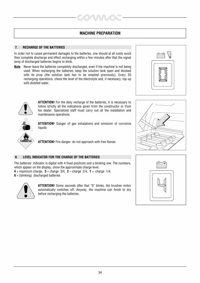
7. RECHARGE OF THE BATTERIES
In order not to cause permanent damages to the batteries, one should at all costs avoidtheir complete discharge and effect recharging within a few minutes after that the signallamp of discharged batteries begins to blink.Note Never leave the batteries completely discharged, even if the machine is not being
used. When recharging the batteries, keep the solution tank open and blockedwith its prop (the solution tank has to be emptied previously). Every 20recharging operations, check the level of the electrolyte and, if necessary, top upwith distilled water.
ATTENTION! For the daily recharge of the batteries, it is necessary tofollow strictly all the indications given from the constructor or fromhis dealer. Specialized staff must carry out all the installation andmaintenance operations.
ATTENTION! Danger of gas exhalations and emission of corrosiveliquids
ATTENTION! Fire danger: do not approach with free flames
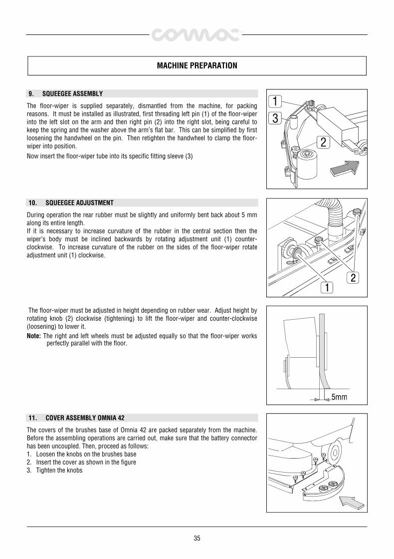
8. LEVEL INDICATOR FOR THE CHARGE OF THE BATTERIES
The batteries’ indicator is digital with 4 fixed positions and a blinking one. The numbers,which appear on the display, show the approximate charge level.4 = maximum charge, 3 = charge 3/4, 2 = charge 2/4, 1 = charge 1/4,0 = (blinking) discharged batteries
ATTENTION! Some seconds after that “0” blinks, the brushes motorautomatically switches off. Anyway, the machine can finish to drybefore recharging the batteries.
35
MACHINE PREPARATION
9. SQUEEGEE ASSEMBLY
The floor-wiper is supplied separately, dismantled from the machine, for packingreasons. It must be installed as illustrated, first threading left pin (1) of the floor-wiperinto the left slot on the arm and then right pin (2) into the right slot, being careful tokeep the spring and the washer above the arm’s flat bar. This can be simplified by firstloosening the handwheel on the pin. Then retighten the handwheel to clamp the floor-wiper into position.Now insert the floor-wiper tube into its specific fitting sleeve (3)
2
31
10. SQUEEGEE ADJUSTMENT
During operation the rear rubber must be slightly and uniformly bent back about 5 mmalong its entire length.If it is necessary to increase curvature of the rubber in the central section then thewiper’s body must be inclined backwards by rotating adjustment unit (1) counter-clockwise. To increase curvature of the rubber on the sides of the floor-wiper rotateadjustment unit (1) clockwise.
The floor-wiper must be adjusted in height depending on rubber wear. Adjust height byrotating knob (2) clockwise (tightening) to lift the floor-wiper and counter-clockwise(loosening) to lower it.Note: The right and left wheels must be adjusted equally so that the floor-wiper works
perfectly parallel with the floor.
11. COVER ASSEMBLY OMNIA 42
The covers of the brushes base of Omnia 42 are packed separately from the machine.Before the assembling operations are carried out, make sure that the battery connectorhas been uncoupled. Then, proceed as follows:1. Loosen the knobs on the brushes base2. Insert the cover as shown in the figure3. Tighten the knobs

36
MACHINE PREPARATION
12. ASSEMBLY ROTATING BRUSHES
1. Push downwards the control lever to lift the brushes baseNote In case of machines with automatic control (machines with actuator) rotate the
switch with key into position ON (1) and push the lever button (2) upwards somuch until the signal lamp of the up-down brushes base is coming off.
2. Turn the key into position OFF and take it off from the instrument board (1)
ATTENTION! To carry out the operations of brushes assembly withconnected current can cause serious damage to the hands.
3. With the brushes base in lifted position, insert the brushes into the seat of the plateunder the base until the three buttons fit into the holes of the plate. Turn the brushso that the buttons are pushed towards their retaining springs until the brush isclamped in place. The figure shows the direction of rotation for the coupling of thebrushes.
4. It is recommended to invert daily the position of the right brush with the left one andvice versa. If the brushes are not new and they show deformed bristles, it is better toreassemble them in the same position, in order to avoid that the different inclinationof the bristles causes an overload to the brushes motor and excessive vibrations.

37
MACHINE PREPARATION
13. TANKS
1. Check that the solution tank is empty, then lift it until the blocking prop is coupled.Check the correct position of the suction hose in its seat (1), that the solution hoseis firmly fixed to the proper connector (2) and that the upper plug is closed (3).
2. Release the prop and lower the solution tank
3. Check that the rear plug (1) and the exhaust one (2) of the recovery tank are closed.
14. SOLUTION WATER
1. Fill the solution tank with clean water at a temperature not more than 50°C and addliquid detergent in the proper concentration following the instructions of themanufacturer. Excess foam in the recovery tank could damage the suction motor, souse only the minimum amount of detergent necessary.
ATTENTION! Always use low foam detergent. To avoid the productionof foam, before starting to clean, put a minimum quantity of antifoamliquid into the recovery tank.
2. Retighten the plug of the solution tank.
ATTENTION! Do absolutely not use pure acid.
38
GENERAL RULES OF SECURITY
The rules below have to be followed carefully in order to avoid damages to the operator and to the machine.
� Read the labels carefully on the machine. Do not cover them for any reason and replace them immediately if damaged
� The machine must be used exclusively by authorized staff that has been instructed for its use
� During the working of the machine, pay attention to other people and especially to the children
� Do not mix different detergents, avoiding harmful odours
� Do not place any liquid containers onto the machine
� The storage temperature has to be between -25°C and +55°C
� The perfect operating temperature should be between 0°C and 40°C
� The humidity should be between 30 and 95%
� Do not use the machine in explosive atmosphere
� Do not use the machine as a means of transport
� Do not use acid solutions which could damage the machine and/or the persons
� Avoid working with the brushes when the machine stands still, in order to prevent floor damages
� Do not vacuum inflammable liquids
� This appliance is not suitable for picking up hazardous dust
� In case of fire, use a powder extinguisher. Do not use water
� Do not strike shelvings or scaffoldings, where there is danger of falling objects
� Adapt the utilization speed to the adhesion conditions
� Do not use the machine on areas having a higher gradient than the one stated on the number plate
� When the machine is in parking position, take off the key and insert the parking brake
� The machine has to carry out simultaneously the operations of washing and drying. Different operations have to be carried outin areas which are not permitted for the passage of non employed staff. Signal the areas of moist floors with suitable signs
� If the machine does not work properly, check by conducting simple maintenance procedures. Otherwise, it is better to ask forCOMAC technical service
� Where parts are required, ask for ORIGINAL spare parts to an agent and/or to an authorized dealer
� Use only original COMAC brushes indicated in the paragraph “CHOICE AND USE OF BRUSHES”
� In case of danger act immediately upon the emergency brake
� Take off the key or remove the battery connector before any maintenance, cleaning or parts’ replacement is done
� Do not take off the pieces which require the use of tools to be removed
� Before using the machine, check that all doors and coverings are in their position as indicated in this use and maintenancecatalogue
� Do not wash the machine with direct water jets or with high water pressure nor with corrosive material
� Every 200 working hours have a machine check through a Comac service department
� The machine should not be abandoned, because of the presence of toxic-harmful materials (batteries, oil etc.). This disposalmust be subject to the rules which provide for its scrapping in appropriate centres
� Be sure the solution tank is empty before lifting it
� In order to avoid scales on the solution tank filter, do not fill the detergent solution many hours before the machines’ use

39
PERFORMANCE
1. Carry out the operations for the preparation of the machine2. Connect the connector to the batteries (1)3. Check that the parking brake is released (2)4. Turn the key of the general switch (3) clockwise of a quarter turn. Immediately, the
general green signal lamp comes on (4) and the digital display indicates the chargelevel of the batteries
2
3 4
ON/OFF
5. Press the brushes motor switch (1)6. Press the suction motor switch (2)Note The machines with automatic version have the functioning of the suction motor
only during forward motion7. Press the solenoid valve switch (3) (only in the automatic versions)8. Adjust the amount of detergent solution through the cock lever (4).
3
21
4
9. Push forward and lift the control lever to lower the brushes base and to adjust itspressure onto the floor (1). In case of machines with actuator, lower the lever button(2) until the yellow lamp comes off (3).
10. Lower the squeegee acting upon the lever (4).Note For the automatic versions see further on in the paragraph “SQUEEGEE
AUTOMATIC MANUAL”
1 2
3 4
11. Pushing forward the lever on the handle bar, the machine begins to move. During thefirst metres of operating, check that the brushes pressure is suitable (see further onunder “BRUSHES PRESSURE”), that the quantity of the detergent solution issufficient and that the squeegee dries perfectly.The machine will now start working efficiently until the detergent solution runs out.

40
PERFORMANCE
ATTENTION! Whenever problems during operating occur, lowerpromptly the lever of the emergency brake placed on the rear rightside of the machine. This command will block immediately the tractionof the machine.To restart the machine again, press the releasing trigger and lift thelever of the emergency brake; then push forward the lever on thehandle bar.
SQUEEGEE AUTOMATIC-MANUAL
The machines with automatic version have the possibility to control electrically thesqueegee movement. Depending on the position of the switch (1) the followingfunctioning systems are activated.Automatic If the switch is placed on automatic, lowering of the squeegee and starting
of the suction motor are obtained with the machine advancement. Also,lifting of the squeegee and stopping of the suction motor are achieved withthe reverse motion of the machine.
Manual If the switch is placed on manual, the squeegee lifts and lowers itselfmanually through the commutator (2). The operation of the suction motoris commanded anyhow through the squeegee.
1 2
AUTO MAN
BRUSHES PRESSURE MANUAL
Brushes pressure can be adjusted through the lever shown in the figure. There are threepredetermined positions. Major is the pressure when the lever is in the highest position.The pressure must be chosen based upon the type of floor and the type of dirt.Excessive pressure causes higher brushes wear and major energy consumption.
BRUSHES PRESSURE WITH AUTOMATIC CONTROL
In case of machines equipped with automatic control (machines with actuator), the leverfor the adjustment of the brushes pressure allows four different levels. Also in this case,major is the pressure onto the brushes when the lever is in its highest position.

41
PERFORMANCE
TRACTION
These machines are equipped with electronically commanded traction, and continuousspeed variation.To move the machine, rotate the key into position ON, wait for three seconds and thenpush forwards (forward movement) or backwards (rear movement) the lever placed onthe handle bar.For safety reasons, in reverse motion, the speed movement is reduced.
ATTENTION! When carrying out even short backward movements,make sure that the squeegee is lifted.
BRAKES
The machine is equipped with two braking systems: a working brake controlled by thelever on the rear left side (2) and a parking and emergency brake controlled by the leverplaced on the rear right side (1).Lower the levers to operate the brakes.The lever of the emergency brake is equipped with a blocking device. To release thisbrake, press the trigger placed on the lever (1) itself.
DEVICE TOO FULL
The machine is equipped with a float, which intervenes when the recovery tank is full. Itsintervention causes the closing of the suction hose. In this case, it is necessary toproceed with the emptying of the recovery tank taking off the plug of the exhaust hose.
RECYCLING OF THE CLEANING SOLUTION
If the machine is equipped with a recycling system of the cleaning solution,for its use refer to the instructions given with the device. In any case, it isnecessary to pay attention to the following recommendations:
• the use of the recycling system must be limited to the cleaning of environmentsnot excessively dirty
• avoid absolutely to treat environments not homogeneous for use and typology ofdirt or anyhow separated between each other
• normally, the treated surface does not have to exceed twice as much of the onetreated without recycling
• remember that the detergent efficacy progressively gets exhausted and it isabsolutely not recommended to make additions in the dirty solution
• clean thoroughly the filters and the tanks at the end of the work

42
ON COMPLETION OF THE WORK
Having finished the job and before any type of maintenance is done, it is necessary to:1. Close the water cock (1)2. Lift the brushes base through the suitable lever if the machine is equipped with
manual control (2) or through the lever button, should the machine be equipped withthe automatic control (3)
Note In case of machines with automatic control act upon the lever button (3) until thesignal lamp of the up-down brushes base is coming off.
3. Lift the squeegee (4). The squeegee has to be lifted when the machine is notoperating. In this way damage to the squeegee rubbers is avoided
Note In case of automatic versions, put the switch into the “MAN” position, in order toavoid that it is being lowered during transfer 3
21
4
4. Switch off the brushes motor switch (1)5. Switch off the suction motor switch (2)6. Bring the machine up to the place provided for the water outlet7. Turn the key into position OFF (3)8. Insert the parking brake
3
21
9. Take off the exhaust pipe from its seat, unscrew the exhaust plug and empty therecovery tank.
ATTENTION! This operation has to be carried out using gloves toprotect from contact with dangerous solutions
10. Take off the brushes and clean them with a water jet (for the brushes disassemblyplease read further on under “DISASSEMBLY OF THE ROTATING BRUSHES”)
11. Clean the squeegee with a water jet.

43
DAILY MAINTENANCE
CLEANING OF THE RECOVERY TANK
1. Empty the recovery tank completely2. Empty the solution tank completely and lift it up to its vertical position blocking it
through the suitable prop3. Unscrew the wing nuts of the recovery tank cover, rotate it of 90° and take it off
4. Take off the rear plug of the recovery tank (1)5. Take off the exhaust hose from its seat and unscrew the plug (2)6. Clean the inside of the recovery tank with a water jet7. Reassemble everything repeating inversely above-mentioned operations
CLEANING OF THE RECOVERY TANK FILTER
1. Empty the solution tank completely and lift it up to its vertical position blocking itthrough the suitable prop
2. Unscrew the filter cover rotating it counterclockwise
ATTENTION! Do not let in water into the hose connected to the filtercover
3. Extract the filter body from its housing and rinse it thoroughly4. Reassemble everything repeating inversely above-mentioned operations
44
DAILY MAINTENANCE
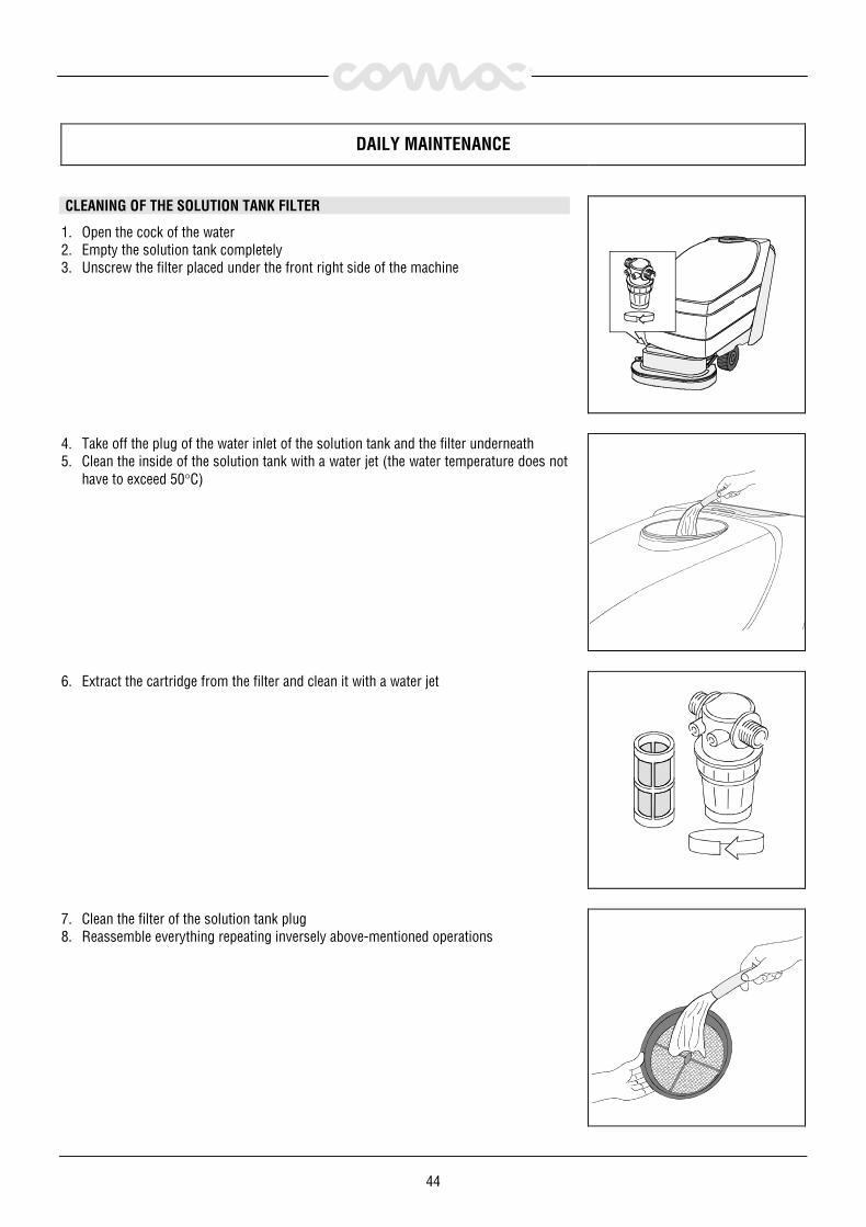
CLEANING OF THE SOLUTION TANK FILTER
1. Open the cock of the water2. Empty the solution tank completely3. Unscrew the filter placed under the front right side of the machine
4. Take off the plug of the water inlet of the solution tank and the filter underneath5. Clean the inside of the solution tank with a water jet (the water temperature does not
have to exceed 50°C)
6. Extract the cartridge from the filter and clean it with a water jet
7. Clean the filter of the solution tank plug8. Reassemble everything repeating inversely above-mentioned operations

45
DAILY MAINTENANCE
CLEANING OF THE SQUEEGEE
In order to have the best drying results, check that the squeegee is always clean. Toclean the squeegee:1. Lift the squeegee through the suitable lever2. Clean accurately the inside of the squeegee with a water jet3. Clean accurately the squeegee rubbers with a water jet4. Check the rubber wear and if necessary, turn them upside-down or change themNote The careful cleaning of the complete suction group assures higher life of the
suction motor.
DISASSEMBLY OF THE ROTATING BRUSHES
1. Lift the brushes base acting upon the suitable handleNote In case of machines with automatic control (machines with actuator), lift the
brushes base acting upon the suitable lever button.2. Rotate the key into position OFF and take if off from the switch
ATTENTION! To carry out the operations of the rotary brushes’disassembly with connected current can cause serious damages tothe hands.
3. Unhook the splash guard rubbers of the brushes base (for the disassembly of thesplash guard rubbers see “REPLACEMENT SPLASH GUARD BRUSHES BASE”)
4. Rotate the brush until it comes off from the brush plate seat as shown in the figure.The figure shows the rotating direction of the brushes disassembly.

46
WEEKLY MAINTENANCE
REPLACEMENT REAR SQUEEGEE RUBBER
If the rear squeegee rubber is worn and does not dry well, it is possible to change thedrying edge proceeding as follows:1. Push and rotate the fixing plates (1)2. Slip off the rubber blade and the rubber itself3. Turn the rubber upside-down and if necessary, replace it4. Reassemble everything repeating inversely above operations5. Adjust the squeegee height depending on the rubber (see under “SQUEEGEE
ADJUSTMENT”)
REPLACEMENT FRONT SQUEEGEE RUBBER
Aspiration is poor and the machine will not dry perfectly if the front floor-wiper rubber isworn. Proceed as follows to replace:
1. Detach the floor-wiper from the machine (1)2. Loosen the screws that clamp the front rubber3. Pull out the rubber-pressing blade4. Pull out and replace the rubberReassemble by repeating these procedures in reverse order
1
REPLACEMENT SPLASH GUARD BRUSHES BASE
Check the condition of the splash guards brushes base. If necessary, to replace them,proceed as follows:1. Loosen the screws (1) which fix the metallic blades2. Take off the splash guard and replace it3. Reassemble everything repeating inversely above operations

47
TROUBLE SHOOTING GUIDE
INSUFFICIENT WATER ONTO THE BRUSHES
1. Make sure that the cock is open (1). In this case the signal lamp must be on (2)2. Make sure that there is water in the solution tank3. In the machines with automatic version check that the solenoid valve switch is on
4. Clean the solution filter
THE MACHINE DOES NOT CLEAN SATISFACTORILY
1. Check the condition of the brushes and replace them, if necessary. The brushes haveto be changed when the bristles reach around 15mm. To work with worn brushescan cause floor damages.
2. Check that the brushes pressure is sufficient (see under “BRUSHES PRESSURE”)3. Use a different kind of brushes to the ones fitted as standard. For cleaning
operations on floors where the dirt proves to be particularly resistant, werecommend using special brushes which may be supplied optionally according toneeds (see under “CHOICE AND USE OF BRUSHES”)
THE SQUEEGEE DOES NOT DRY PERFECTLY
1. Check that the squeegee is clean2. Check the squeegee adjustments (see under “MACHINE PREPARATION”)3. Clean the whole suction group (see under “DAILY MAINTENANCE”)4. Replace the rubbers, if worn (see under “WEEKLY MAINTENANCE”)

48
TROUBLE SHOOTING GUIDE
THE SUCTION MOTOR DOES NOT FUNCTION
1. Check that the signal lamp of the suction motor switch is on2. Check whether the recovery tank is full; eventually empty it3. In the automatic versions, the suction motor works only when the squeegee is
lowered. Check that the selector is on the “AUTO” position and move forward ofsome metres.
4. Check the perfect float condition of the recovery tank filter (see under “CLEANING OFTHE RECOVERY TANK FILTER”)
EXCESSIVE FOAM PRODUCTION
Check that a low foam detergent has been used. If required, add a small quantity ofantifoam liquid into the recovery tank.Remember that, when the floor is not very dirty, more foam is generated. In this casedilute more the detergent.

49
CHOICE AND USE OF BRUSHES
POLYPROPYLENE BRUSH (PPL)It is used on all types of floors, which are hot water resistant (not more than 60°C). The Polypropylene brush is nonhygroscopicand therefore conserves its characteristics even if working in the wet conditions.
NYLON BRUSHIt is used on all types of floors with excellent wear and hot water resistance (more than 60°C). The nylon is hygroscopic and so,over time, looses its characteristics working on the wet.
ABRASIVE BRUSHThe brush bristles are charged with very aggressive abrasives. It is used to clean very dirty floors. To avoid floor damages, workstrictly only with the necessary pressure.
STEEL BRUSHThe bristles are made of steel wires or flat blades or can be mixed, by means of steel and synthetic fibres. The steel wire brush isused to descale very uneven floors or with wide joints. The brush with steel blades is used to scrape off more resistantincrustations.
THICKNESS OF THE BRISTLESThe thicker the bristles are, the more rigid they will be. These ones are therefore used on smooth floors or with small joints.On uneven floors with deep joints it is recommended that, softer bristles, which enter more easily in depth, are used.Please bear in mind that, when the bristles are worn out and get too short, they will get rigid and cannot penetrate anymore. Aswell as for thick bristles, the brush will begin to jump.
PAD HOLDERThe pad holder is recommended to clean glossy areas.There are two types of pad holders:1. The traditional pad holder is equipped with anchor points, which allow the abrasive pad to be held and dragged during the
work process.2. The pad holder is of the CENTER LOCK type, apart from the anchor points, is equipped with a central blocking release system
made in plastic. This allows a perfect match with the abrasive pad and to hold it without the risk of falling down. This type ofpad holder is recommended especially for machines with more brushes, where the centering of the pads is difficult.
LIST FOR THE CHOICE OF THE BRUSHES
Machine Q.ty Code Bristles type Thickn.∅∅∅∅ ∅∅∅∅ Brushes Notes
OMNIA26 2
668070106680702066807030668070406680705066718010
PPLPPLPPLABRASIVESTEELPad holder Center Lock
0.30.60.91
345345345345345335 Pad blocking
OMNIA32 2
668030106680302066803030668030406680305066703020
PPLPPLPPLABRASIVESTEELPad holder Center Lock
0.30.60.91
0.3
430430430430430410 Pad blocking
OMNIA42 2
668170106681702066817030668170406681705066710040
PPLPPLPPLABRASIVENYLONad holder Center Lock
0.90.60.31
0.9
533533533533533510 Pad blocking

50

51
SOMMAIRE
LIVRAISON DE LA MACHINE .................................................................................................................. 52AVANT-PROPOS ................................................................................................................................ 52CARACTERISTIQUES TECHNIQUES........................................................................................................... 52SYMBOLES SUR LA MACHINE ................................................................................................................ 53SYMBOLE DANS LE MANUEL ................................................................................................................. 55PREPARATION DE LA MACHINE .............................................................................................................. 56
1. DEPLACEMENT DE LA MACHINE EMBALLEE ............................................................................................................................................ 562. COMME ENLEVER L’EMBALLAGE A LA MACHINE..................................................................................................................................... 563. CONNEXION DU CABLE DE MOTEUR DE TRACTION................................................................................................................................. 564. MONTAGE DES BATTERIES DANS LA MACHINE....................................................................................................................................... 575. CONNEXION CONNECTEUR DES BATTERIES ............................................................................................................................................ 576. CONNEXION DE LA PRISE DE CHARGE BATTERIE.................................................................................................................................... 577. RECHARGE BATTERIE............................................................................................................................................................................... 588. INDICATEUR DE DECHARGE DE LA BATTERIE.......................................................................................................................................... 589. MONTAGE SUCEUR .................................................................................................................................................................................. 5910. REGLAGE SUCEUR.................................................................................................................................................................................. 5911. MONTAGE DU CARTER DE BROSSE DE LA OMNIA 42............................................................................................................................ 5912. MONTAGE DES BROSSES ROTATIVES.................................................................................................................................................... 6013. RESERVOIRS .......................................................................................................................................................................................... 6114. SOLUTION D’EAU PROPRE ..................................................................................................................................................................... 61
NORMES GENERALES DE SECURITE......................................................................................................... 62EMPLOI DE LA MACHINE ...................................................................................................................... 63
SUCEUR AUTOMATIQUE-MANUEL ................................................................................................................................................................ 64PRESSION DES BROSSES MANUELLE .......................................................................................................................................................... 64PRESSION DES BROSSES AVEC COMMANDE AUTOMATIQUE...................................................................................................................... 64TRACTION ..................................................................................................................................................................................................... 65FREINS........................................................................................................................................................................................................... 65DISPOSITIF TROP PLEIN ............................................................................................................................................................................... 65RECYCLAGE DE LA SOLUTION DE LAVAGE .................................................................................................................................................. 65
A LA FIN DE L’EXPLOITATION................................................................................................................. 66ENTRETIEN JOURNALIER...................................................................................................................... 67
NETTOYAGE DU RESERVOIR DE RECUPERATION ......................................................................................................................................... 67NETTOYAGE FILTRE DU RESERVOIR DE RECUPERATION ............................................................................................................................ 67NETTOYAGE DES FILTRES DU RESERVOIR DE SOLUTION............................................................................................................................ 68NETTOYAGE DU SUCEUR............................................................................................................................................................................... 69DEMONTAGE DES BROSSES ROTATIVES ...................................................................................................................................................... 69
ENTRETIEN HEBDOMADAIRE ................................................................................................................. 70REMPLACEMENT BAVETTE ARRIERE DU SUCEUR........................................................................................................................................ 70REMPLACEMENT BAVETTE AVANT DU SUCEUR ........................................................................................................................................... 70REMPLACEMENT BAVETTE DE PROTECTION CARTER DES BROSSES.......................................................................................................... 70
CONTROLE DE FONCTIONNEMENT........................................................................................................... 71L’EAU SUR LES BROSSES EST INSUFFISANTE.............................................................................................................................................. 71LA MACHINE NE NETTOIE PAS CORRECTEMENT .......................................................................................................................................... 71LE SUCEUR NE SECHE PAS PARFAITEMENT ................................................................................................................................................. 71L’ASPIRATION NE FONCTIONNE PAS ............................................................................................................................................................ 72PRODUCTION EXCESSIVE DE MOUSSE......................................................................................................................................................... 72
CHOIX ET UTILISATION DES BROSSES ...................................................................................................... 73

52
Livraison de la machine
Au moment de la livraison, contrôler immédiatement si on areçu toute la marchandise comme indiquée sur les documentset si la machine n’a pas été endommagée au cours du transport.En ce cas indiquer immédiatement au transporteur le type dedommages en informant également notre agence. C’est le seulmode d’action, qui, mis en pratique à temps vous permettrad’obtenir un dédommagement.
Avant-propos
C’est une autolaveuse qui utilise l’action mécanique d’abrasionréalisée par deux brosses rotatives et l’action chimique du à unesolution détergente capable de nettoyer n’importe quel sol etramassant pendant sa phase de travail les salissures et lasolution détergente non absorbée par le sol.La machine doit être utilisée seulement pour ce but. Unentretien soigné et rigoureux est une garantie pour laproductivité maximale de la machine. Nous vous prions de bienvouloir lire cette brochure d’instruction pour la mise en route etl’entretien de votre machine. En cas de nécessité, nos servicestechniques sont à disposition pour tout conseil ou intervention.
CARACTERISTIQUES TECHNIQUES U.M. OMNIA26 OMNIA32 OMNIA42Largeur de travail mm 660 830 1040Largeur de suceur mm 1015 1115 1315Capacité de travail, jusqu'à mc/h 2640 3320 4160Brosses ∅ mm 345 430 533Vitesse de rotation Tr/mn 220 210 170Pression des brosses maximum kg 80 80 80Pression spécifique maximum sur les brosses g/cmc 57 36 33Voltage moteur des brosses V 36 36 36Puissance moteur des brosses W 1250 1250 1500Voltage moteur de traction V 36 36 36Puissance moteur de traction W 300 450 450Traction aut. aut. aut.Vitesse d’avance km/h 0÷4 0÷4 0÷4Pente maximum 10% 10% 10%Voltage moteur d’aspiration V 36 36 36Puissance moteur d’aspiration W 560 560 560Dépression mbar 190 190 190Capacité réservoir d’eau propre l 75 105 105Capacité réservoir d’eau sale l 85 115 115Longueur machine mm 1600 1650 1750Hauteur machine mm 1120 1120 1120Largeur machine (sans suceur) mm 700 850 760Compartiment des batteries mm 436x614xH510Batteries V/Ah 36/285 36/285 36/285Poids des batteries kg 305 305 305Poids de la machine (à vide et sans les batteries) kg 205 240 290Niveau de pression acoustique (conformément aux normes IEC 704/1) dB(A) <70 <70 <70Niveau de vibration m/sc 1.72 1.72 1.72