padeye calculation example
TRANSCRIPT
COMPANYPROJECTSUBJECT
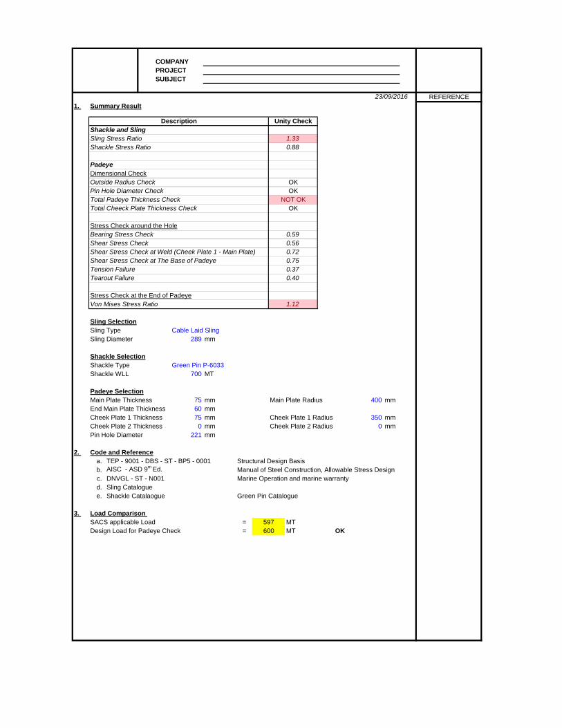
1. Summary Result
Shackle and SlingSling Stress RatioShackle Stress Ratio
PadeyeDimensional CheckOutside Radius CheckPin Hole Diameter CheckTotal Padeye Thickness CheckTotal Cheeck Plate Thickness Check
Stress Check around the HoleBearing Stress CheckShear Stress CheckShear Stress Check at Weld (Cheek Plate 1 - Main Plate)Shear Stress Check at The Base of PadeyeTension FailureTearout Failure
Stress Check at the End of PadeyeVon Mises Stress Ratio
Sling SelectionSling Type Cable Laid SlingSling Diameter mm
Shackle SelectionShackle Type Green Pin P-6033Shackle WLL MT
Padeye SelectionMain Plate Thickness mm Main Plate Radius mmEnd Main Plate Thickness mmCheek Plate 1 Thickness mm Cheek Plate 1 Radius mmCheek Plate 2 Thickness mm Cheek Plate 2 Radius mmPin Hole Diameter mm
2. Code and Referencea. TEP - 9001 - DBS - ST - BP5 - 0001 Structural Design Basisb. AISC - ASD 9th Ed. Manual of Steel Construction, Allowable Stress Designc. DNVGL - ST - N001 Marine Operation and marine warrantyd. Sling Catalogue e. Shackle Catalaogue Green Pin Catalogue
3. Load Comparison SACS applicable Load = MTDesign Load for Padeye Check = MT OK
0 0221
289
700
75 400
75 350
597600
60
0.720.750.370.40
1.12
0.88
0.590.56
NOT OKOK
23/09/2016 REFERENCE
Description Unity Check
1.33
OKOK
COMPANYPROJECTSUBJECT
23/09/2016 REFERENCE
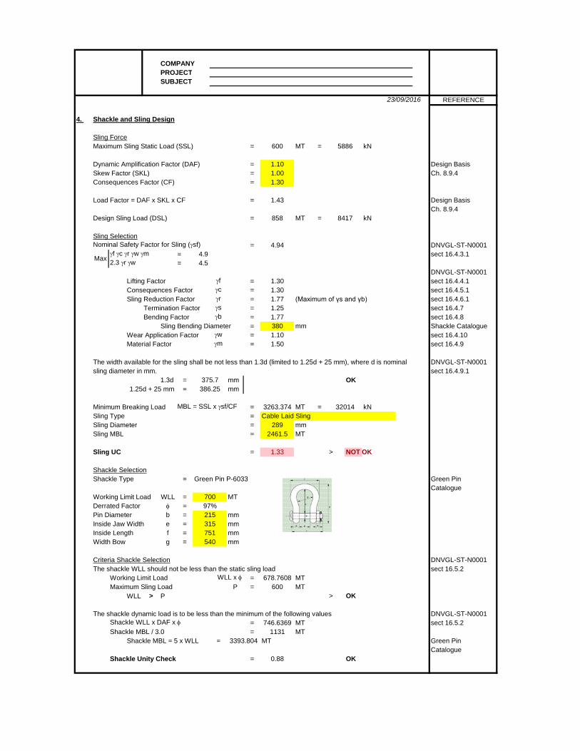
4. Shackle and Sling Design
Sling ForceMaximum Sling Static Load (SSL) = MT = kN
Dynamic Amplification Factor (DAF) = Design BasisSkew Factor (SKL) = Ch. 8.9.4Consequences Factor (CF) =
Load Factor = DAF x SKL x CF = Design BasisCh. 8.9.4
Design Sling Load (DSL) = MT = kN
Sling SelectionNominal Safety Factor for Sling (γsf) = DNVGL-ST-N0001
γf γc γr γw γm = 4.9 sect 16.4.3.12.3 γr γw = 4.5
DNVGL-ST-N0001Lifting Factor γf = sect 16.4.4.1Consequences Factor γc = sect 16.4.5.1Sling Reduction Factor γr = (Maximum of γs and γb) sect 16.4.6.1
Termination Factor γs = sect 16.4.7Bending Factor γb = sect 16.4.8
Sling Bending Diameter = mm Shackle CatalogueWear Application Factor γw = sect 16.4.10Material Factor γm = sect 16.4.9
The width available for the sling shall be not less than 1.3d (limited to 1.25d + 25 mm), where d is nominal DNVGL-ST-N0001sling diameter in mm. sect 16.4.9.1
1.3d = mm OK1.25d + 25 mm = mm
Minimum Breaking Load MBL = SSL x γsf/CF = MT = kNSling Type = Cable Laid SlingSling Diameter = mmSling MBL = MT
Sling UC = > NOT OK
Shackle SelectionShackle Type = Green Pin P-6033 Green Pin
CatalogueWorking Limit Load WLL = MTDerrated Factor φ =Pin Diameter b = mmInside Jaw Width e = mmInside Length f = mmWidth Bow g = mm
Criteria Shackle Selection DNVGL-ST-N0001The shackle WLL should not be less than the static sling load sect 16.5.2
Working Limit Load WLL x φ = MTMaximum Sling Load P = MT
WLL > P > OK
The shackle dynamic load is to be less than the minimum of the following values DNVGL-ST-N0001Shackle WLL x DAF x φ = MT sect 16.5.2Shackle MBL / 3.0 = MT
Shackle MBL = 5 x WLL = MT Green Pin Catalogue
Shackle Unity Check = OK0.88
751
678.7608600
746.63691131
3393.804
540
2892461.5
1.33
700
215315
3801.101.50
3263.374
97%
375.7386.25
32014
Max
1.301.301.771.251.77
1.001.30
1.43
858 8417
4.94
600 5886
1.10
COMPANYPROJECTSUBJECT
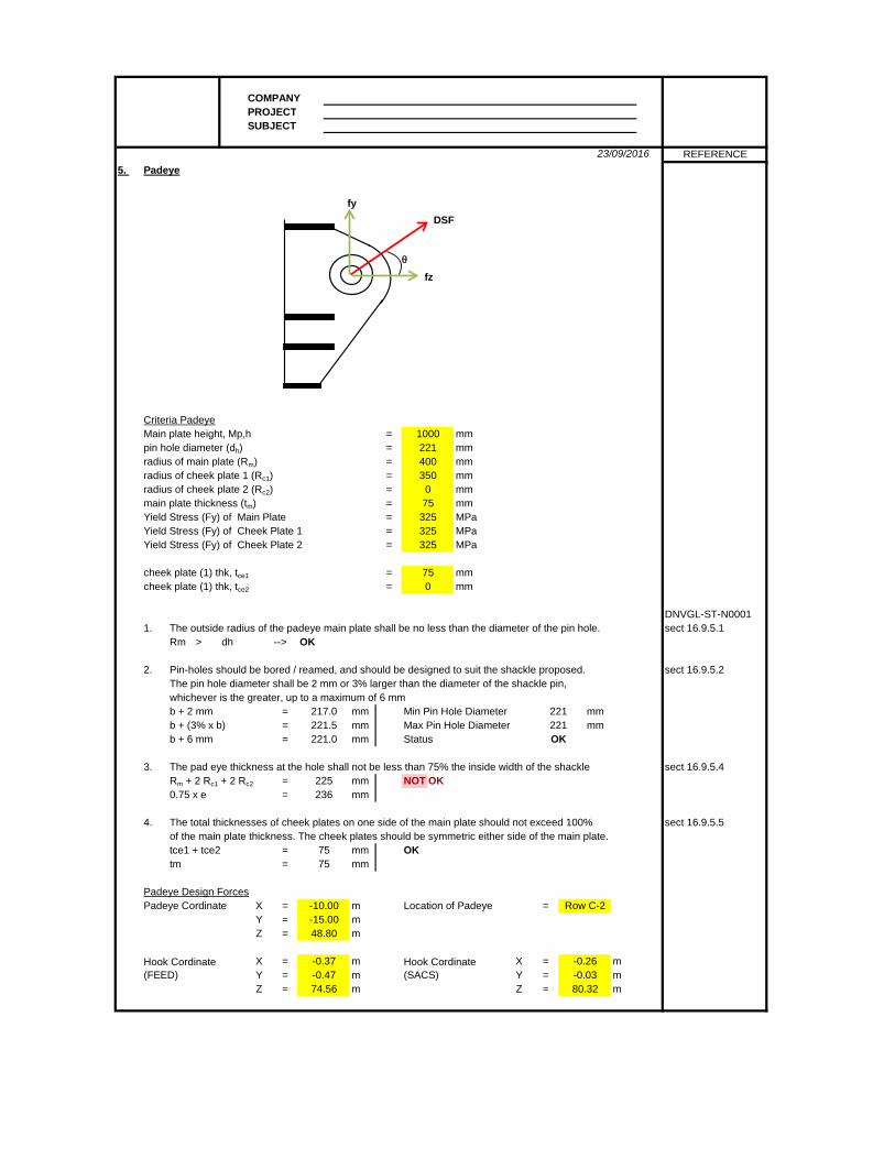
23/09/2016 REFERENCE5. Padeye
Criteria PadeyeMain plate height, Mp,h = mmpin hole diameter (dh) = mmradius of main plate (Rm) = mmradius of cheek plate 1 (Rc1) = mmradius of cheek plate 2 (Rc2) = mmmain plate thickness (tm) = mmYield Stress (Fy) of Main Plate = MPaYield Stress (Fy) of Cheek Plate 1 = MPaYield Stress (Fy) of Cheek Plate 2 = MPa
cheek plate (1) thk, tce1 = mmcheek plate (1) thk, tce2 = mm
DNVGL-ST-N00011. The outside radius of the padeye main plate shall be no less than the diameter of the pin hole. sect 16.9.5.1
Rm > dh --> OK
2. Pin-holes should be bored / reamed, and should be designed to suit the shackle proposed. sect 16.9.5.2The pin hole diameter shall be 2 mm or 3% larger than the diameter of the shackle pin,whichever is the greater, up to a maximum of 6 mmb + 2 mm = mm Min Pin Hole Diameter mmb + (3% x b) = mm Max Pin Hole Diameter mmb + 6 mm = mm Status
3. The pad eye thickness at the hole shall not be less than 75% the inside width of the shackle sect 16.9.5.4Rm + 2 Rc1 + 2 Rc2 = mm NOT OK0.75 x e = mm
4. The total thicknesses of cheek plates on one side of the main plate should not exceed 100% sect 16.9.5.5of the main plate thickness. The cheek plates should be symmetric either side of the main plate.tce1 + tce2 = mm OKtm = mm
Padeye Design ForcesPadeye Cordinate X = m Location of Padeye =
Y = mZ = m
X = m X = mY = m Y = mZ = m Z = m
Hook Cordinate (FEED)
Hook Cordinate (SACS)
-10.00-15.0048.80
-0.37-0.4774.56
-0.26-0.0380.32
Row C-2
75
217.0221.5221.0
225236
75
75325325325
750
221221OK
1000221400350
0
DSF
fz
fy
θ
COMPANYPROJECTSUBJECT
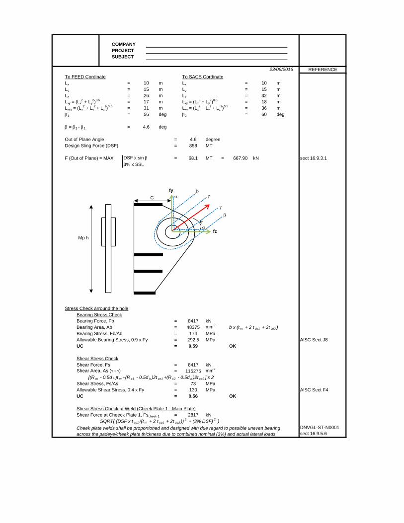
23/09/2016 REFERENCETo FEED Cordinate To SACS CordinateLx = m Lx = mLy = m Ly = mLz = m Lz = mLxy = (Lx
2 + Ly2)0.5 = m Lxy = (Lx
2 + Ly2)0.5 = m
Lxyz = (Lx2 + Ly
2 + Lz2)0.5 = m Lxy = (Lx
2 + Ly2 + Lz
2)0.5 = mβ1 = deg β2 = deg
β = β2 - β1 = deg
Out of Plane Angle = degreeDesign Sling Force (DSF) = MT
F (Out of Plane) = MAX DSF x sin β = MT = kN sect 16.9.3.13% x SSL
Stress Check arround the holeBearing Stress CheckBearing Force, Fb = kNBearing Area, Ab = mm2 b x (t m + 2 t ce1 + 2t ce2 )Bearing Stress, Fb/Ab = MPaAllowable Bearing Stress, 0.9 x Fy = MPa AISC Sect J8UC = OK
Shear Stress CheckShear Force, Fs = kNShear Area, As (γ - γ) = mm2
[(R m - 0.5d h )t m +(R c1 - 0.5d h )2t ce1 +(R c2 - 0.5d h )2t ce2 ] x 2Shear Stress, Fs/As = MPaAllowable Shear Stress, 0.4 x Fy = MPa AISC Sect F4UC = OK
Shear Stress Check at Weld (Cheek Plate 1 - Main Plate)Shear Force at Cheeck Plate 1, Fscheek 1 = kN
SQRT( (DSF x t ce1 /(t m + 2 t ce1 + 2t ce2 )) 2 + (3% DSF) 2 )DNVGL-ST-N0001sect 16.9.5.6
731300.56
2817
Cheek plate welds shall be proportioned and designed with due regard to possible uneven bearingacross the padeye/cheek plate thickness due to combined nominal (3%) and actual lateral loads
48375174
292.50.59
8417115275
4.6858
68.1
1731
26
1015
56
4.6
667.90
8417
1836
101532
60
fz
fy
θ
γ
γ
β
β
C
Mp h
α
α

COMPANYPROJECTSUBJECT
23/09/2016 REFERENCE
Fillet Weld Size, tw1 = mmFillet yield Strength, Fyw = MPa (70 ksi)Weld Shear Area, Aw1 = mm2 0.707 x Π x R c1 x t w1
Shear Stress at Weld, Fscheek1/Aw1 = MPaAllowable Shear Stress, 0.3 x Fyw = MPaUC = OK
Shear Stress Check at The Base of PadeyeShear Force, FsBase = kN DSF sin θ θ = 60 degShear Area, AsBase = mm2
Shear Stress = MPaAllowable Shear Stress, 0.4 x fy = MPa AISC Sect F4UC = OK
Tension and Tearout FailureTension Force, Ft = kNArea at Cross Section, At (α - α) = mm2
[(R m - 0.5d h )t m +(R c1 - 0.5d h )2t ce1 +(R c2 - 0.5d h )2t ce2 ] x 2Tension Stress, Ft/At = MPaAllowable Tensile Stress, 0.6 x fy = MPa AISC Sect D1UC = OK
Tearout Area, As (β - β) = mm2 t m ( Π R c1 x 2R m )Tearout Stress, Fs/As = MPaAllowable Shear Stress, 0.45 x fy = MPa AISC Sect D3.1UC = OK
Stress Check at the end of padeye
Main plate height, Mph = mmMain plate thickness, Mpt = mmStiffener Plate 1 width, t1w = mmStiffener Plate 1 thickness, t1t = mmStiffener Plate 2 width, t2w = mmStiffener Plate 2 thickness, t2t = mmStiffener Plate 3 width, t3w = mmStiffener Plate 3 thickness, t3t = mmStiffener Plate 4 width, t4w = mmStiffener Plate 4 thickness, t4t = mmDepth 1, d1 = mmDepth 2, d2 = mmDepth 3, d3 = mmCentre of pinhole to base of padeye, C = mmNeutral Axis, na = mm from top of stiffener 1
4400
550542.35
0.000.000.00
550.0040.00
0
0.40
100060
400.0040.000.00
731950.37
14246759
146
7500097
1300.75
8417115275
48227209
1041450.72
7289
35
taw taw
COMPANYPROJECTSUBJECT
23/09/2016 REFERENCE
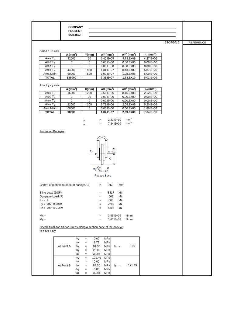
About x - x axis
About y - y axis
Ixx = mm4
Iyy = mm4
Forces on Padeyes
Centre of pinhole to base of padeye, C = mm
Sling Load (DSF) = kNOut-pane Load (F) = kNFx = F = kNFy = DSF x Sin θ = kNFz = DSF x Cos θ = kN
Mx = = NmmMy = = Nmm
Check Axial and Shear Stress along a section base of the padeyefs = fvx + fxy
fvy = MPafvx = MPafbx = MPa fs =fby = MPafaz = MPafvy = MPafvx = MPafbx = MPa fs =fby = MPafaz = MPa
At Point B
121.490.0084.35 121.490.0030.94
72894208
3.58.E+093.67.E+08
At Point A
0.008.7984.35 8.7923.0230.94
2.22.E+107.34.E+09
550
8417668668
TOTAL 98000 1.04.E+07 2.89.E+09 7.34.E+09Area Main 60000 0 0.00.E+00 0.00.E+00 1.80.E+07
Area T4 22000 305 6.71.E+06 2.05.E+09 5.20.E+09Area T3 0 0 0.00.E+00 0.00.E+00 0.00.E+00
2.12.E+09Area T2 0 30 0.00.E+00 0.00.E+00 0.00.E+00
A (mm2) X(mm) AX (mm3) AX2 (mm4) Iyy (mm4)Area T1 16000 230 3.68.E+06 8.46.E+08
TOTAL 136000 7.38.E+07 1.73.E+10 5.01.E+09Area Main 60000 500 3.00.E+07 1.08.E+08 5.00.E+09
Area T4 44000 980 4.31.E+07 8.43.E+09 5.87.E+06Area T3 0 0 0.00.E+00 0.00.E+00 0.00.E+00Area T2 0 0 0.00.E+00 0.00.E+00 0.00.E+00Area T1 32000 20 6.40.E+05 8.73.E+09 4.27.E+06
A (mm2) Y(mm) AY (mm3) AY2 (mm4) Ixx (mm4)
COMPANYPROJECTSUBJECT
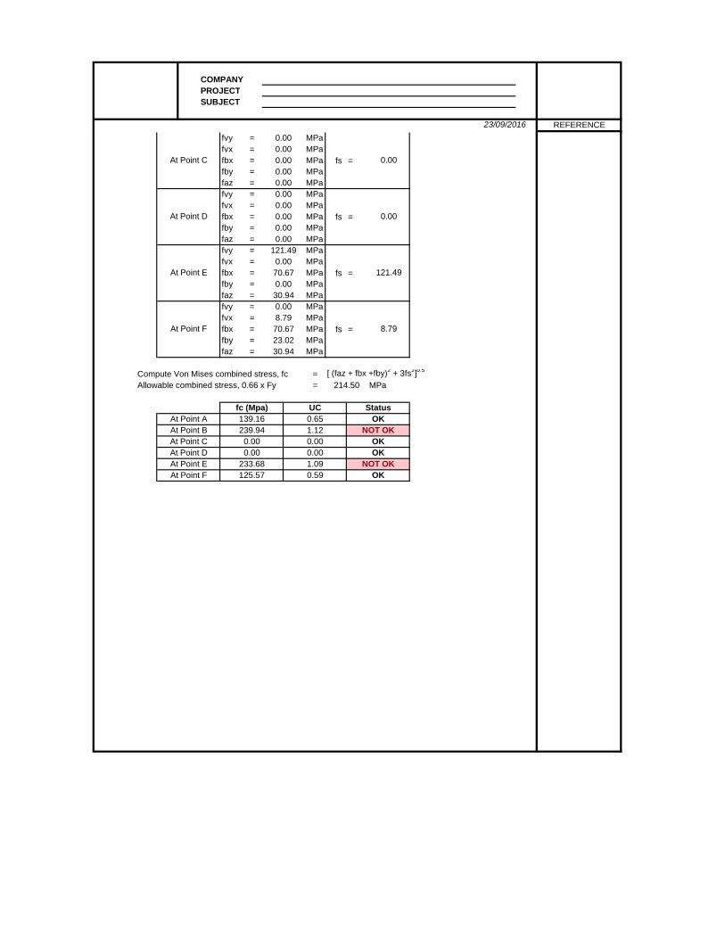
23/09/2016 REFERENCEfvy = MPafvx = MPafbx = MPa fs =fby = MPafaz = MPafvy = MPafvx = MPafbx = MPa fs =fby = MPafaz = MPafvy = MPafvx = MPafbx = MPa fs =fby = MPafaz = MPafvy = MPafvx = MPafbx = MPa fs =fby = MPafaz = MPa
Compute Von Mises combined stress, fc = [ (faz + fbx +fby)2 + 3fs2]0.5
Allowable combined stress, 0.66 x Fy = MPa
At Point F 125.57 0.59 OK
At Point D 0.00 0.00 OKAt Point E 233.68 1.09 NOT OK
At Point B 239.94 1.12 NOT OKAt Point C 0.00 0.00 OK
214.50
fc (Mpa) UC StatusAt Point A 139.16 0.65 OK
At Point F
0.008.7970.67 8.7923.0230.94
At Point E
121.490.0070.67 121.490.0030.94
At Point D
0.000.000.00 0.000.000.00
At Point C
0.000.000.00 0.000.000.00