paderborn cpu core for approximate computing
TRANSCRIPT

Paderborn CPU Core for ApproximateComputingDesign Document
September 30, 2016
Contents
1 Introduction 3
2 System Architecture Overview 52.1 Hardware-Side . . . . . . . . . . . . . . . . . . . . . . . . . . . . . . . . . 52.2 Software-Side . . . . . . . . . . . . . . . . . . . . . . . . . . . . . . . . . . 5
3 Approximation Techniques 73.1 Description of Existing Core . . . . . . . . . . . . . . . . . . . . . . . . . . 73.2 Approximate Arithmetic Logic Unit (ALU) . . . . . . . . . . . . . . . . . 10
3.2.1 Control Parameters for the ALU . . . . . . . . . . . . . . . . . . . 103.2.2 Changes to the Instruction Set . . . . . . . . . . . . . . . . . . . . 12
3.3 Lookup Table-based Approximation Unit (LUT) . . . . . . . . . . . . . . 133.3.1 Proposed HW Unit . . . . . . . . . . . . . . . . . . . . . . . . . . . 133.3.2 Compiler Interface . . . . . . . . . . . . . . . . . . . . . . . . . . . 153.3.3 Changes to CPU Core . . . . . . . . . . . . . . . . . . . . . . . . . 153.3.4 Changes to the Instruction Set . . . . . . . . . . . . . . . . . . . . 16
3.4 Testing . . . . . . . . . . . . . . . . . . . . . . . . . . . . . . . . . . . . . 18
4 Compiler/Language 214.1 Programmer’s Interface . . . . . . . . . . . . . . . . . . . . . . . . . . . . 21
4.1.1 Predefined Preprocessor Macros . . . . . . . . . . . . . . . . . . . 214.1.2 Pragma Directives . . . . . . . . . . . . . . . . . . . . . . . . . . . 214.1.3 Decorators . . . . . . . . . . . . . . . . . . . . . . . . . . . . . . . 224.1.4 Arithmetic Operation Approximation . . . . . . . . . . . . . . . . 244.1.5 Function Approximation . . . . . . . . . . . . . . . . . . . . . . . . 25
4.2 Compiler Frontend . . . . . . . . . . . . . . . . . . . . . . . . . . . . . . . 274.2.1 Lexical/Syntactical Analysis . . . . . . . . . . . . . . . . . . . . . . 274.2.2 Semantic Analysis . . . . . . . . . . . . . . . . . . . . . . . . . . . 27
1

4.2.3 Translation . . . . . . . . . . . . . . . . . . . . . . . . . . . . . . . 274.2.4 Code Generation . . . . . . . . . . . . . . . . . . . . . . . . . . . . 28
4.3 Compiler Backend . . . . . . . . . . . . . . . . . . . . . . . . . . . . . . . 294.3.1 Assembly Code Generation . . . . . . . . . . . . . . . . . . . . . . 294.3.2 Assembly . . . . . . . . . . . . . . . . . . . . . . . . . . . . . . . . 294.3.3 Linking . . . . . . . . . . . . . . . . . . . . . . . . . . . . . . . . . 29
4.4 LUT Configuration Generator . . . . . . . . . . . . . . . . . . . . . . . . . 294.4.1 Input Format . . . . . . . . . . . . . . . . . . . . . . . . . . . . . . 304.4.2 Intermediate Format . . . . . . . . . . . . . . . . . . . . . . . . . . 304.4.3 Weights Format . . . . . . . . . . . . . . . . . . . . . . . . . . . . . 314.4.4 Output Format . . . . . . . . . . . . . . . . . . . . . . . . . . . . . 324.4.5 Architecture Specification Format . . . . . . . . . . . . . . . . . . 324.4.6 Approximating Strategy . . . . . . . . . . . . . . . . . . . . . . . . 324.4.7 Keyvalue Summary . . . . . . . . . . . . . . . . . . . . . . . . . . . 344.4.8 Command-line Options . . . . . . . . . . . . . . . . . . . . . . . . 34
4.5 Testing Regime . . . . . . . . . . . . . . . . . . . . . . . . . . . . . . . . . 35
5 Conclusions 35
2
1 Introduction
The PACO (Paderborn CPU Core for Approximate Computing) development platformis a project group effort by students and advisors of the University of Paderborn. Ap-proximate Computing, as we understand it, provides calculation facilities to applicationprogrammers that allow them to trade off precision or probability-of-correctness for otherdesired qualities: e.g. reduced delay, higher energy efficiency.We perceive a lack of a complete stack of tools and general-purpose computing platformto evaluate new approximate implementations of functional units (hardware). Withour development platform, we want to enable exploration of new approximate hardwarecomponents in an ordinary general-purpose processor.This includes the whole stack:
• A modular RISC-V processor template with attached peripherals (memory, UARTetc.) synthesizable to FPGA.
• An easy-to-extend compiler toolchain that allows hardware developers to createnew (approximate) opcodes and programmers to write code (annotated C++)that can be compiled into machine code containing those approximate opcodes.
• A testing framework to test new instructions and hardware functional units in anautomated fashion.
• Example applications that are compiled using our toolchain.
• A QEMU just-in-time binary translation testbench for approximate applications.
• Two complex approximate functional unit designs useful for approximation, inte-grated into the CPU pipeline as examples.
We have chosen two previously unexplored approaches of approximate functional unitsto integrate in the pipeline: One is an approximate ALU capable of common ALUoperations (e.g. +, −, ∗) but with different possible degrees of precision, specified atapplication compile time. The other, less conventional, functional unit is supposed toevaluate complex functions approximately, functions which are not normally present asstand-alone instructions in a processor. Underlying technology is a Lookup Table.This Design Document is not an all-encompassing high-detail specification of the com-plete platform, but a succinct description of our goals, critical design problems, proposedsolutions and specification of interfaces between work packages, allowing us to compart-mentalize implementation.The next section “2 System Architecture Overview” contains an outline of the wholePACO platform, hardware and software, as well as references to sections explaining thedetails of each component. Section 3 – “Approximation Techniques” is a detailed de-scription of the proposed inner workings of the proposed approximate functional units inthe CPU as well as interfaces towards the compiler and the CPU. Section 4 – “Compil-er/Language” – contains a specification of all compiler interfaces, towards the applicationprogrammer and the hardware. Section 5 is the Conclusion for our Design phase.
3

To external readers we would also like to point out that other documents precede thisDesign Documentation: The Project Plan (stating our timeline and detailing our av-enues of exploration) and Exploration Documentation (summing up the results of ourexploration of the design space and setting up our design decisions).
4

CPU (modified RISC V)
IF ID EX MEM WB
LUT
precise ALU
approx. ALU
RAM
PACO core
Figure 1: Overview of the hardware core design.
2 System Architecture Overview
The PACO Approximate Computing System laid out in this document is composed ofhardware and software. The approximate hardware components created by our groupare functional units in the execution stage of the pipeline, which can perform the ap-proximate operations required by applications.The software primarily consists of a compiler toolchain that allows a user to generatebinaries that can compute approximate results on the hardware created in this project.
The rest of this section will outline the PACO system architecture as an orientationaid for the design description in sections 3 and 4.
2.1 Hardware-Side
An overview of the hardware has been presented in the Project Plan document. For ref-erence, Figure 1 is included as an update of the core overview presented in the ProjectPlan: We have chosen the Rocket[1] chip implementation of the RISC-V ISA as a tem-plate for extension with approximate functionality. We must modify the ISA (see Sec-tions 3.1, which means modifying the decoder, and we will add new functional units tothe execution stage of the processor pipeline. These new functional units are an ALUcapable of approximate calculations (see Section 3.2) and a Lookup Table unit capableof approximate evaluation of complex functions (see Section 3.3).
2.2 Software-Side
Our compiler system is built on the CLANG frontend for C/C++, an LLVM backendused for code optimization and target code generation as well as the binutils from theRISC-V toolchain that allow assembly and linking executables.Every stage of this toolchain will be extended by us to support the approximation unitsadded to the RISC-V processor, see Figure 2.
5

CLANG LLVM
LUT compiler
analysis translation optimization code generation
binutilsassembly linking
LLVMIR
RISC-Vassembly
elf(.bss)
elf(executable)
annotatedC/C++
Figure 2: Overview of the compiler toolflow used by PACO. Parts that will be modifiedor created by us are set in bold italic.
Modifications to the CLANG frontend include analysis and translation stages (see Sec-tion 4.2). Frontend output is LLVM intermediate representation (IR) code (see Table11), which is going to be extended to support additional instructions for our approxima-tion units.The LLVM backend (Section 4.3) optimization steps are mostly independent of the ex-tensions made to the IR and thus do not need to be modified. In contrast, the codegeneration stage (Section 4.3.1) is extended to translate approximate instructions fromthe LLVM IR to RISC-V-targeted assembly code, requiring extension of assembly lan-guage mnemonics to include approximate instructions. These additional mnemonics arethen converted to binary object code by the RISC-V binutils assembler. Finally thebinutils linker (Section 4.3.3) must combine all object code into a single binary file.
Lookup Table Configuration Generator One of the proposed approximate functionalunits is a programmable Lookup Table (LUT) in the execution stage of the pipeline.This LUT is supposed to evaluate complex (normally not included in an instruction set)functions approximately. Configuration for the LUT functional units has to be gener-ated on a per-application and per-complex-function basis. So, in parallel to the normalcompiler toolchain, specifications for Lookup table usage must be extracted from sourcecode in the CLANG frontend and processed in a separate program called the LUT com-piler or LUT configuration generator (see Section 4.4). This program inputs source coderepresenting a function to be approximated and outputs object code containing staticdata representing the configuration and ROM bitstreams of a Lookup table.
Immediately after loading a program the Lookup table hardware components areconfigured according to the previously generated bitstream (see Section 4.4.4). Sincemultiple compilation units may yield LUTs, knowledge of all the configurations is notpresent before the linking stage. Thus the linker must also manage LUT hardware coresand assign configuration bitstreams to them as well as translating LUT-related instruc-tions to use the correct LUT hardware core.
6

3 Approximation Techniques
A useful method of approximate computing must create a benefit in exchange for theerror introduced during computation. Approximation techniques allow this exchange,but the exchange rates depend on the application: e.g. one application might be tolerantof a certain percentage of calculations being plain wrong (error rate) while another mightbe tolerant of all calculations deviating by a certain amount from the correct result(deviation).
We have designed two approximation techniques trading off correctness for energyefficiency and/or reduction of computation delay. These will be specified in this section.
3.1 Description of Existing Core
We will implement our approximate functional units in a RISC-V processor. As a basisfor understanding the proposed modifications, this subsection explains relevant structureand behaviour of the the Rocket System-on-Chip we will use as a template for PACO.
RISC-V The RISC-V processors are written in Chisel 1. Chisel is a new open sourcehardware construction language developed at UC Berkeley that supports advanced hard-ware design in an extension of the Scala programming language. It raise the level of ab-straction of a hardware design by providing concepts like object orientation, functionalprogramming, parameterized types and type inference.A hardware description provided in Chisel is generated into appropriate low-level Verilogcode.
ISA The RISC-V ISA is composed of modules [2]. Each module defines an interface fora functionality in the ISA. The RISC-V ISA is defined as a base integer ISA. The baseinteger ISA is very similar to that of early RISC processors like MIPS or OpenRISC.The difference is that RISC-V has no branch delay slots and supports optional variable-length instruction encodings. Each base integer instruction set is characterized by thewidth of the integer registers and the corresponding size of the user address space.Each implementation of the RISC-V ISA has to implement the basic modules, eitherRV32I or RV64I. Any other module is optional. The base integer ISA can be extendedwith one or more optional instruction-set extensions, but the base integer instructionscannot be redefined.
Extensions RISC-V is divided into standard and non-standard extensions.Standard extensions are useful for common applications and do not conflict with otherstandard extensions. Non-standard extensions are specialized and may conflict withother non-standard extensions as well as standard extensions, not needed for this exten-sion. If possible, conflicts between standard extensions should be avoided.
1https://chisel.eecs.berkeley.edu/
7
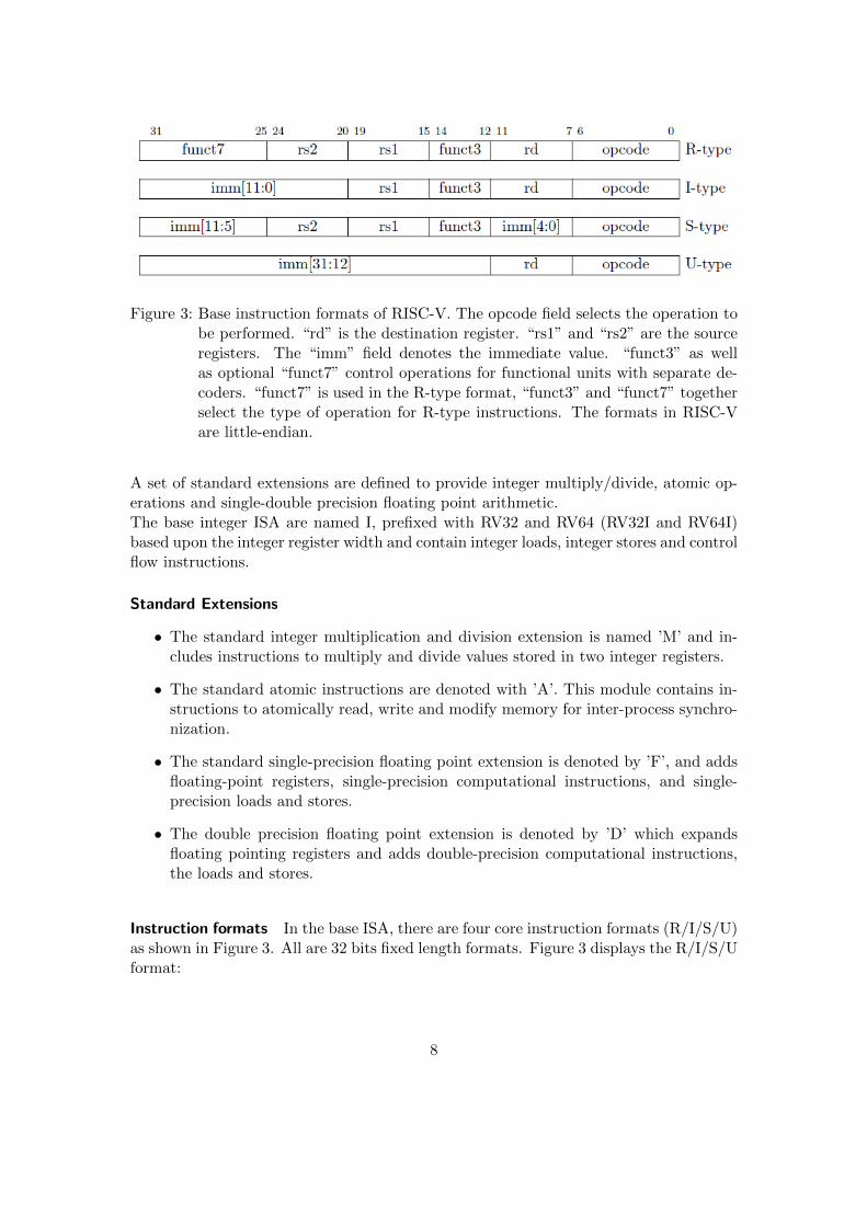
Figure 3: Base instruction formats of RISC-V. The opcode field selects the operation tobe performed. “rd” is the destination register. “rs1” and “rs2” are the sourceregisters. The “imm” field denotes the immediate value. “funct3” as wellas optional “funct7” control operations for functional units with separate de-coders. “funct7” is used in the R-type format, “funct3” and “funct7” togetherselect the type of operation for R-type instructions. The formats in RISC-Vare little-endian.
A set of standard extensions are defined to provide integer multiply/divide, atomic op-erations and single-double precision floating point arithmetic.The base integer ISA are named I, prefixed with RV32 and RV64 (RV32I and RV64I)based upon the integer register width and contain integer loads, integer stores and controlflow instructions.
Standard Extensions
• The standard integer multiplication and division extension is named ’M’ and in-cludes instructions to multiply and divide values stored in two integer registers.
• The standard atomic instructions are denoted with ’A’. This module contains in-structions to atomically read, write and modify memory for inter-process synchro-nization.
• The standard single-precision floating point extension is denoted by ’F’, and addsfloating-point registers, single-precision computational instructions, and single-precision loads and stores.
• The double precision floating point extension is denoted by ’D’ which expandsfloating pointing registers and adds double-precision computational instructions,the loads and stores.
Instruction formats In the base ISA, there are four core instruction formats (R/I/S/U)as shown in Figure 3. All are 32 bits fixed length formats. Figure 3 displays the R/I/S/Uformat:
8

• R-type instructions are register type instructions, most integer and floating pointcomputations use R-type format for register-register operations. Along with integerand floating point computations, atomic memory operations (AMO) instructionsare encoded in R-type instruction format.
• I-type instructions are shorthand for immediate instructions. Integer computationsusing register-immediate operations are encoded using I-type format. Apart fromthe integer computation indirect jump instruction (JALR), loads, shifts and systeminstruction uses I-type encoding.
• Store instructions are encoded using S-type format.
• Load upper immediate(LUI) uses U-type format. This instruction is used to build32-bit constants and places the U-immediate value in the top 20 bits of the des-tination register, filling in the lowest 12 bits with zeroes. AUIPC (add upperimmediate to PC2) also build PC-relative addresses using U-type format.
For our scalable ALU we plan to use R-type format for our instructions. The RISC-VISA keeps the source (rs1 and rs2) and destination (rd) registers at the same positionin all formats to simplify decoding. Immediate values are packed towards the leftmostavailable bits in the instruction and have been allocated to reduce hardware complexity.In particular, the sign bit for all immediate values is always in bit 31 of the instructionto speed up sign-extension circuitry.
Rocket Core The implementation of the RISC-V architecture, the Rocket Core, im-plements the 32-bit instruction set which can handle both 32-bit and 64-bit operands.The CPU contains 31 registers. The core works with six pipeline stages:
1. pcgen - generates the program counter value
2. fetch - fetches the instruction
3. decode - decodes the instruction
4. execute - the execution phase
5. mem - access to memory
6. commit - commits the result
A detailed overview can be found in ([1], page 13). All basic extensions are implementedin the Rocket Core, so all functions of the ISA are available and a floating point unit isincluded.Some functions need more than one cycle. A scoreboard takes care of data hazards thatcould occur while using functions like ”DIV”. All computations are done in user mode.The supervisor mode will be used for trap and interrupt handling.
2program counter
9

3.2 Approximate Arithmetic Logic Unit (ALU)
To attain scalable approximation, we designed a scalable ALU unit inside the pipeline,specifically in the decode/execution phase. The basic idea for our scalable ALU unit is toapproximate operands rather than ALU function itself, before processing the operands.The main idea is that a number of LSBs3 can be neglected if the application toleratessome specific error rate. This depends on required quality of results specified by theprogrammer. The approximation of operands takes place before the execution phaseand after the decode phase.
Arithmetic operations are good candidates for approximation since they are morecomplex and consume much more energy than logical and shift operations. Our de-sign supports approximate instructions for the ADD, SUB and MUL operations. Asneglecting bits in a division operation can produce undefined results, division is left out.Arithmetic operations with immediate values are also supported by the core, but aremostly used for control flow and less in normal arithmetic computations. Adding ap-proximate instructions for them will add to the complexity of the decode phase withoutgreat promise. More details on approximate instructions are shown in Section 3.2.2.
Scalable ALU The design in Figure 4 shows the circuitry to approximate operands ofcertain arithmetic operations, before feeding them to the ALU or the Multiplier unit.Approximation of operands is scalable by different levels according to 6 approximationbits present in the instruction format of approximate instructions. Approximation isdone by neglecting number of LSBs from each operand and replacing them with zeros.The graph shows the modification to one of the ALU input operands. A control sig-nal, id precsie, is set to zero if the operation is approximate. id app bits are the bitsresponsible for defining the degree of approximation.
Table 1 gives information on the number of LSBs being ignored for each level of ap-proximation and its corresponding encoding. The 7 encoding bits represent the 6 bitsobtained from the instruction concatenated with the control bit (as the right-most). I.e.the control bit is always 0, which means the instruction is approximate. This designvariant gives a maximum of 27 bits approximation and minimum of 2 bits.
From Table 1 it can be concluded that we never approximate last 5 bits (27 to 31) asthey form the MSB of the number – a 100% approximation can be achieved by leavingout the instruction.
3.2.1 Control Parameters for the ALU
As already mentioned, the approximation logic is provided with 6 bits defining the ap-proximation level. These must be present in the instruction format of every approximate
3The least significant bit is the lowest bit in a series of numbers in binary.
10

Figure 4: approximating input operands of ALU.
Encoding bits No of bits approximated
level 1 1111110 2 lsb neglectedlevel 2 1111100 4 lsb neglectedlevel 3 1111000 7 lsb neglectedlevel 4 1110000 10 lsb neglectedlevel 5 1100000 15 lsb neglectedlevel 6 1000000 20 lsb neglectedlevel 7 0000000 27 lsb neglected
Table 1: Encoding of approximation bits.
11
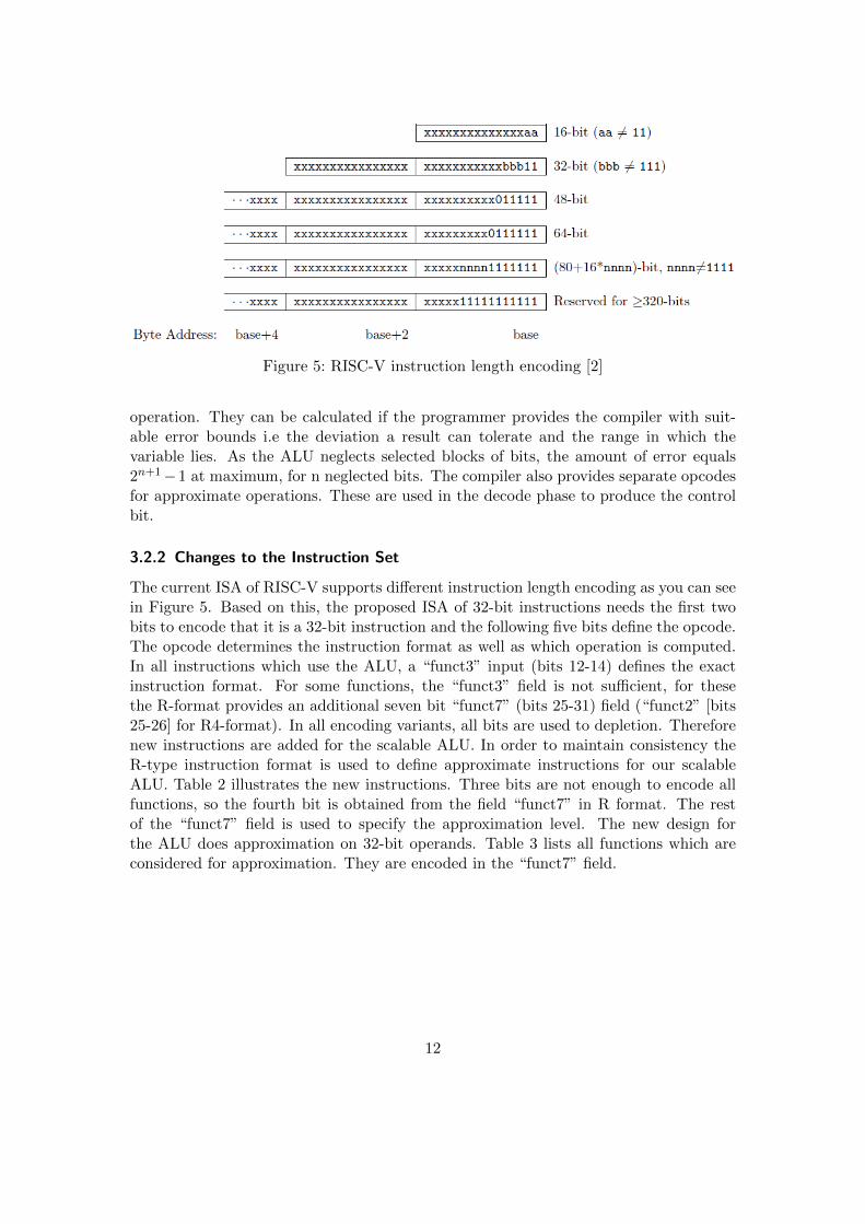
Figure 5: RISC-V instruction length encoding [2]
operation. They can be calculated if the programmer provides the compiler with suit-able error bounds i.e the deviation a result can tolerate and the range in which thevariable lies. As the ALU neglects selected blocks of bits, the amount of error equals2n+1−1 at maximum, for n neglected bits. The compiler also provides separate opcodesfor approximate operations. These are used in the decode phase to produce the controlbit.
3.2.2 Changes to the Instruction Set
The current ISA of RISC-V supports different instruction length encoding as you can seein Figure 5. Based on this, the proposed ISA of 32-bit instructions needs the first twobits to encode that it is a 32-bit instruction and the following five bits define the opcode.The opcode determines the instruction format as well as which operation is computed.In all instructions which use the ALU, a “funct3” input (bits 12-14) defines the exactinstruction format. For some functions, the “funct3” field is not sufficient, for thesethe R-format provides an additional seven bit “funct7” (bits 25-31) field (“funct2” [bits25-26] for R4-format). In all encoding variants, all bits are used to depletion. Thereforenew instructions are added for the scalable ALU. In order to maintain consistency theR-type instruction format is used to define approximate instructions for our scalableALU. Table 2 illustrates the new instructions. Three bits are not enough to encode allfunctions, so the fourth bit is obtained from the field “funct7” in R format. The restof the “funct7” field is used to specify the approximation level. The new design forthe ALU does approximation on 32-bit operands. Table 3 lists all functions which areconsidered for approximation. They are encoded in the “funct7” field.
12

XXXXXX X XXXXX XXXXX XXX XXXXX 0001011
approx funct4 rs2 rs1 funct3-1 rd opcode31-26 25 24-20 19-15 14-12 11-7 6-0
Table 2: New opcode for the scalable ALU
Function Opcode (Funct4)
ADD.APPROX 0000SUB.APPROX 0001MUL.APPROX 0010FADD.S.APPROX (Single precision Add floating point) 0100FSUB.S.APPROX (Single precision Sub floating point) 0101FMUL.S.APPROX (Single precision Mul floating point) 0110FSQRT.S.APPROX (Single precision Sqrt floating point) 1100FADD.D.APPROX (Double precision Add floating point) 1000FSUB.D.APPROX (Double precision Sub floating point) 1001FMUL.D.APPROX (Double precision Mul floating point) 1010FSQRT.D.APPROX (Double precision Sqrt floating point) 1101
Table 3: Function opcodes for the ALU
3.3 Lookup Table-based Approximation Unit (LUT)
3.3.1 Proposed HW Unit
The LUT unit is used to approximate arithmetic functions. The input range of a function(domain) will be divided into segments. The value of the function will be approximatedfor each segment either as a constant value or an affine function (defined by slope andbase).
The LUT unit supports integer and fixed-point operations. For the current designonly integers are considered. Extending the unit to process floating-point values willneed extra hardware. This is left to later phases of our work. The LUT unit consistsof three reconfigurable logic planes and a small ROM. An overview of the LUT unitarchitecture can be seen in Figure 6.
The ROM will store the approximated values of the arithmetic function for differentsegments of the domain. As a starting point for our design, the memory is addressedwith eight bits, has 256 entries and implemented in SRAM technology. It has one portfor reading and writing.
In order to achieve approximation of arithmetic functions with piecewise affine func-tions, two values, slope and offset, are stored for each segment. The slope is multipliedby the input value and then the offset is added. This will need extra hardware; namelytwo ROMs to store slope and offset values, a multiplier and an adder. The Architectureof the component is shown in Figure 7.
13

AND plane
Connection plane
OR plane
ROM
MUX
input
Figure 6: Architecture overview of the LUT unit
As Figure 6 shows, the signals from the OR-plane are used to address the ROM.This means only eight OR gates are needed. Ignoring optimization effects, the numberof AND gates corresponds to the number of segments where the arithmetic functionis sampled. For our current design, the AND-plane has eight inputs, along with theirinverted values, and 256 gates. To select the eight relevant bits from the 32-bit inputs,the selection-plane is used.
The states of the cross points, connected or disconnected, in the three reconfigurableplanes have to be stored in some memory structure. As this memory will not be accessedby the CPU memory address scheme, a simple structure of shift registers as shown inFigure 8 is sufficient. Data is copied to the registers using a simple memory interface. Ifthe “write enable” signal is enabled, new data is written to the upper register, and olderdata is shifted to the next register. The connection-plane, AND-plane and OR-planehave 32x8, 16x256 and 8x256 cross points respectively. These 6400 values are generatedby the compiler and loaded to main memory at program load time.
After implementing the LUT unit, the time delay of the complete unit will be estimatedto decide if the lookup operation can finish in one cycle. If not, the lookup can beimplemented as a multi-cycle operation and the CPU pipeline will be stalled.
14

ROM
MUX
ROM
MUX
Result
Mu
ltip
ly
8 From OR plane
Input
Ad
d
Figure 7: Using 2 ROMs to store values of slope and offset in one segment. 32 MUXsare used for 32 bit values stored in ROM, only one is shown here.
3.3.2 Compiler Interface
For the configuration of the LUT, the configuration data is generated by the compilerand loaded into main memory at program start time. It is later copied to the LUTin corresponding fields, the ROM and the shift registers, probably using DMA. Thisdata contains 256 approximated values of the original arithmetic function. These valuesare to be stored in LUT memory. The configuration data also contains a bit streamrepresenting the states of the cross points in the three reconfigurable planes. This isthen copied into the corresponding shift registers shown in Figure 8.
3.3.3 Changes to CPU Core
The LUT is part of the execution stage of the pipeline. Its input can handle 32-bitoperands (may be extended to 64-bit) from a register. But not all input bits from theregister can be used as AND plane input. The input is limited by the size of the LUTreconfigurable planes. The output contains a 32-bit (or, extended, 64-bit) operand.Depending on the size of the LUT (the proposed values are only starting points for the
15

Memory interface
Data
Write enable
Shift register
Figure 8: Memory interface to the shift register storing cross points states
implementation), it will take more than one cycle to look up the result. An acceptabletrade-off of size, accuracy and space has to be evaluated during implementation. Ifthe lookup takes more than one cycle, the processor has to use stalls. The LUT willbe used for complex functions, so potential for improvement remains, compared to thecomputation the processor would do without using the LUT.All LUTs will be programmed by loading the values from the memory by initializationof the LUT at program load time. Execution on the LUT has to wait until the LUT isconfigured. Initialization time also depends on the size of the LUT. If easily achievablewith the Rocket SoC, the data is loaded with DMA, to prevent the CPU from blockingduring configuration time.
3.3.4 Changes to the Instruction Set
The LUT unit expects four instructions to be supported by the processor.Each of the instructions operates on a single LUT hardware core and thus has a selectionfield specifying which LUT core to use.LUTL (table 4) performs a reset or configuration operation, transmitting a single wordof configuration data.
16

LUTS (table 5) queries the status of a LUT hardware core writing the result into adestination register.LUTE (table 7) starts a computation on a LUT hardware core writing the result into adestination register. It accepts one or two input registers.LUTW (table 9) performs identically to LUTE, however no computation is performed.
Table 4: LUTL
lutl rs1, lutsel, 0, reset/conf
00 000 XX XXXXX XXXXX XXX XXXX X 0101011
func2 reserved lutsel[4:3] reserved rs1 lutsel[2:0] reserved reset/conf. opcode31-30 29-27 26-25 24-20 19-15 14-12 11-8 7 6-0
“funct2” selects the function, lutsel selects which LUT to configure, “rs1” is the sourceregister for the LUT programming (ignored if reset/conf is set to 1), “reset, conf.” is toindicate whether to reset or configure the LUT, resetting the LUT core if set to 1 andloading a configuration word otherwise.
Table 5: LUTS
luts rd, lutsel
10 000 XX XXXXXXXXXX XXX XXXXX 0101011
func2 res lutsel[4:3] reserved lutsel[2:0] rd opcode31-30 29-27 26-25 24-15 14-12 11-7 6-0
“funct2” selects the function, lutsel selects which LUT to retrieve the status from and“rd“ indexes the register to store the status in.
The instructions are encoded to fit into the R-format of the RISC-V ISA like mostfunctions in the execution pipeline stage of the Rocket Core do. It also reduces the sizeof the decoder to fit into one instruction format. Since there is a little difference to theR-format we name this format the A (for approximate) format. If configuration of theLUT with the DMA works fine, the first instruction will only be a pseudo-instruction.The size of LUT units is subject to the trade-off between energy consumption and level ofapproximation (number of segments). Depending on this, it will be possible to implementmore or less LUTs. If the LUT is configured by DMA can be used to address more LUTunits. This has to be evaluated during the implementation.
17

Table 6: LUTE
lute rd, rs1, lutsel, strange
lute2 rd, rs1, rs2, lutsel, strange
01 X XX XX XXXXX XXXXX XXX XXXXX 0101011
func2 charm strange lutsel[4:3] rs2 rs1 lutsel[2:0] rd opcode31-30 29 28-27 26-25 24-20 19-15 14-12 11-7 6-0
Table 7: “funct2” and “opcode” identify the operation, “lutsel” selects which LUT touse, “rs1” and “rs2” are source registers for LUT input and, “rd” is the desti-nation register. “charm” determines if two source registers are used (1) or just“rs1” (0). “strange” is used to determine what LUT inputs are supplied with“rs1” and “rs2”. The following table shows how the three input words of theLUT core are affected by this instruction. “keep” signifies that the previouslyused word is kept as input.The “charm” bit is not part of the instruction’s mnemonic and is instead en-coded in its name: use “lute” for 0 and “lute2” for 1.
charm strange input 1 input 2 input 3
0 00 rs1 keep keep0 01 keep rs1 keep0 10 keep keep rs10 11 keep keep keep
1 00 rs1 rs2 keep1 01 keep rs1 rs21 10 rs2 keep rs11 11 keep keep keep
3.4 Testing
Hardware Approximate ALU and LUT units must be tested to check if they functionproperly and produce the expected results. The approximate results obtained are thencompared to the accurate results to check if error margins specified by the programmerare violated.
After implementing an ALU approximation technique, the design can be tested withdifferent operations, different operands and different values of neglect-amount. Testdata will be prepared manually at first. It does not have to wait for or depend onthe tool-chain. Scripts will automate feeding of data to the implemented hardware,collect results, compare to accurate results and return a human-readable summary tothe hardware developer.
The same applies for the LUT unit. Values stored in ROM and states of connection-
18

Table 8: LUTW
lutw rs1, lutsel, strange
lutw2 rs1, rs2, lutsel, strange
11 X XX XX XXXXX XXXXX XXX 00000 0101011
func2 charm strange lutsel[4:3] rs2 rs1 lutsel[2:0] res opcode31-30 29 28-27 26-25 24-20 19-15 14-12 11-7 6-0
Table 9: “funct2” and “opcode” identify the operation, “lutsel” selects which LUT touse, “rs1” and “rs2” are source registers for LUT input. “charm” determinesif two source registers are used (1) or just “rs1” (0). “strange” is used to de-termine what LUT inputs are supplied with “rs1” and “rs2”. The followingtable shows how the three input words of the LUT core are affected by thisinstruction. “keep” signifies that the previously used word is kept as input.The “charm” bit is not part of the instruction’s mnemonic and is instead en-coded in its name: use “lutw” for 0 and “lutw2” for 1.
charm strange input 1 input 2 input 3
0 00 rs1 keep keep0 01 keep rs1 keep0 10 keep keep rs10 11 keep keep keep
1 00 rs1 rs2 keep1 01 keep rs1 rs21 10 rs2 keep rs11 11 keep keep keep
Table 10: LUTE3
lute3 rd, rs1, rs2, rs3, lutsel
“LUTE3” is intended as a pseudo-instruction, to be translated with:
lutw2 rs1, rs2, lutsel, 0
lute rd, rs3, lutsel, 2
plane cross points are generated manually for certain arithmetic functions. Then differentlookup operations can be performed to check if the hardware design functions properly.
In a later phase of our work when the complete tool-chain is developed, standard testbenches will be used to measure the degradation of precision corresponding to different
19

levels of approximation.
Applications For the applications we want to run on PACO, we will create a QEMUemulation of our system so we can quickly check if the application is processed correctlywhen approximate instructions are binary-translated to a precise analogue of their func-tionality. This will speed up development and bug-hunting since it enables us to provideerror-free test cases for the hardware with higher probability.
20
4 Compiler/Language
The PACO language/compiler needs to offer programmers access to approximate com-putation units via an interface.
To this end we add annotations specifying types and functions as approximable to theCLANG C/C++ frontend. These annotations also specify additional parameters usedto determine the configuration of applicable approximation techniques.
On the backend side of the compiler, binaries will be created, integrating additionalsections for Lookup Table configuration data as well our new approximate instructions.
4.1 Programmer’s Interface
For an approximate interpretation of the source code, a developer needs to annotatetypes or whole sections of code as approximate. The design of these annotations is thetopic of this section. In general, we introduce type annotations and pragma commands,extending the CLANG C/C++ LLVM frontend.
Type annotations are used to derive characteristics of fine-grained approximation tech-niques such as the approximated ALU implemented in our core. Annotating function-s/invocations serves to mark entire sections of code as approximable which by default istranslated to a Lookup Table approximation unit.
The language extension itself is designed with extendability in mind: All annotationsfollow the same syntax using a construct called the approximation decorator, or justdecorator for short. Such a decorator is a list of named arguments called key-value pairsor simply key-values that specify method and degree of approximation to be used.Any later additions to the set of approximation units may use the same decorator andsimply change the set of values it contains.
4.1.1 Predefined Preprocessor Macros
The extended CLANG compiler defines the macro paco in order to allow distinguishingbetween PACO-aware and PACO-unaware compilers and thus write code compilable byboth kinds of compilers.
4.1.2 Pragma Directives
Additional configuration can be done to set up compiler behavior. This is done throughpragma statements:
• #pragma paco combine <mode>: When an operation is performed on operandswith different levels of precision, a resulting precision must be derived to configurethe underlying approximate functional unit and to infer the result type.The method to be used in such a scenario can be set with this pragma instruction.Permissible values for mode are:
21

– least precise Combines all operands’ precision levels so that the result willbe no more precise than any of the operands. If for example the first operandis precise in any but the least four bits and a second operand is imprecisein exactly the seventh-least significant bit, the result will be imprecise in thefour least significant bits as well as the seventh-least significant bit.In terms of ALU instructions, the precision masks of the operands will beand -combined (see Table 1).
– most precise Combines all operands’ precision levels so that the result willno less precise than any of the operands. If for instance the first operand isimprecise in four least significant bits and the second one is imprecise in two,the result will be imprecise in only the two least significant bits.In terms of ALU instructions, the precision masks of the operands will beor -combined (see Table 1).
– error Operation on inputs of differing precision is considered an error.
The value of this pragma defaults to error.
• #pragma paco intermediate literal <mode> Sets what precision a literal shouldhave that occurs alongside a decorated type as input to an arithmetic expression.This scenario occurs on binary operators and the ternary comparison operator.For binary operators the imprecise type to mimic in a literal is well-defined as thereis only one other operand. For the ternary comparison operator, the first operandholds a special purpose as the selector thus the type to mimic is also well-defined.Possible values for mode are:
– precise All literals are of their respective precise type. This is the defaultsetting.
– mimic A literal assumes the same type as an imprecise type occurring alongwith it.
4.1.3 Decorators
Besides selecting modes of operation through pragma directives as discussed in the pre-vious section, the main way to exploit approximate functional units is use of decorators.A decorator is a set of key-value pairs attached to a type / function definition or afunction invocation.The available keys and the acceptable type and meaning of assigned values depend on theapproximation unit to be used and will be explained further in the appropriate sectionsfor instruction-level approximation using the approximate ALU (Arithmetic operationapproximation) and function-level approximation using Lookup tables ( Function ap-proximation).
Approximation decorator To mark a syntax element of the source code as approximableand specify parameters on its approximation, an approximation decorator is used. This
22

is a set of key-value pairs enclosed in approx() . The value assigned to a key must bea literal:
approx_decorator ::= ( ’approx’ ’(’ approx_keyvalue+ ’)’ )+
approx_keyvalue ::= ident ’=’ literal
Example:
approx( neglect_amount=2 inject=1 )
(Note that the key-value pairs in this example do not reflect actual key-values used, butserve to illustrate the syntax only.)
The set of available keys and the expected types depends on the context in which thedecorator is used. If multiple approximation decorators are specified, they are evaluatedin order of appearance. This means that any key-value specified in a preceding decoratoris superseded by values assigned to the same key in any succeeding decorator.
The syntax of the approximation decorator has been chosen explicitly to allow anno-tated code to be compiled with any C compiler, ignoring approximation annotations. Todo this, a simple macro resolves all approximation decorators to nothing:
#ifndef __paco
#define approx(...)
#endif
Approximate types An approximate type is any simple data type decorated with anapproximation decorator. It is used to specify approximation parameters for individualvariables that is used to derive approximable operations.
approx_type ::= type_declaration approx_decorator
Example:
typedef int approx( neglect_amount=2 inject=1 ) int2;
typedef float approx( neglect_amount=4 ) float4;
typedef int4 approx( neglect_amount=7 inject=0 relax=1) int7;
If the base type is already approximate, any additionally specified keys supersede thosedefined in the original type definition. In the above example, int8 keeps the key-valueneglect amount=4 from its int4 base type but overrides inject=1 to inject=0.
Approximate functions To utilize coarse-grained approximation facilities such as LookupTables or Neural Processing Units, entire blocks of code must be evaluated at once. Thiscan be achieved by decorating a function definition, thereby applying approximation tothe entire function body. Approximate functions are defined by appending an approxi-mation decorator after the argument list. Example:
float function1(float a) approx( strategy="lut" ) {
return sqrt(a);
}
23

Approximate invocations If only a specific invocation of a function is to be approx-imated or it is to be approximated differently than it was specified in the functiondefinition, the invocation itself can be decorated with an approximation decorator, too.The effect is identical to copying the called function definition and applying the addi-tional decorator to the duplicate function definition.Decorating a function invocation follows the following syntax:
approx_invoc ::= identifier approx_decorator ’(’ argument_list ’)’
Example:
float a=approx( strategy="lut" ) sqrt(b);
4.1.4 Arithmetic Operation Approximation
One approximation technique of the PACO core is an approximate ALU which allows toneglect a number of bits of the operands. Neglecting bits in this case leaves the outputof the operation in those bits as undefined. Usage of this is determined by the types ofinputs and the assignment target of an arithmetic operation.Literal inputs are considered precise while variable inputs may have decorated types.Operation approximation understands these key-values:
• neglect amount: An integer specifying the number of bits to neglect. Valid num-bers are: 2, 4, 7, 10, 15, 20 and 27. For further information, refer to Table 1. Notethat this cannot be used in conjunction with mask (see below).
• mask: A 6 bit integer encoding the bit neglect mask according to Table 1. Notethat in contrast to using neglect amount, this way neglected bits can be selectedmore freely allowing intermediate bits to be neglected and less significant ones tobe left precise. Note that this cannot be used in conjunction with neglect amount.
• inject: If set to a non-zero integer, this variable is considered to be imprecisethus operations having this as an input can operate approximately. This is usedto denote that the source of data found in variables of this type are expected notto deliver exact values thus approximation can be performed even if the result isto be handled as precise.
• relax: If set to a non-zero integer (default), operations assigning to a variableof this type can be regarded as approximable. This is used to denote that theresult of an operation does not need to be exact thus even with precise inputsapproximation is performed.
Considering an expression tree involving decorated types as inputs and as assignmenttarget, translation occurs as follows:First, any neglect amount specification is translated into a neglect mask according toTable 1.
24

If the assignment target is annotated with the relax key-value, its neglect mask is ap-plied to the root operation of the expression tree and propagates downwards towardsthe leaves of the expression tree.Together with this back-propagated neglect, a forward-propagated neglect is computedfor each node of the expression tree by combining the neglect masks of the immediateinputs starting at the leafs.If both operands have an identical neglect mask, it is applied to the operation as is.If the neglect masks are different, they are combined according to the combine pragma.A literal assumes a neglect mask according to the intermediate literal pragma.An illustration of forward and backward propagation can be seen in Figure 9 for anexpression tree of x = a + (b · c).After both the forward and backward propagated neglect values are computed, they arecombined by picking the least precise of the two. This decision is sound as can be seenby the following elaboration:If the forward-propagated neglect allows more precision than is required by the back-propagated neglect, the additional precision is unnecessary by definition.If the forward-propagated values are less precise than the back-propagated neglect ac-cepts, additional precision in the operations yields random data as the input was alreadyrandom.
For each operation that can be approximated, error propagation must be computed.This is a function that dictates the neglect mask of the result type of this operationdepending on the neglect masks of the operation itself. Alongside this, the inversefunction needs to be computed as well in order to allow back-propagation to computewhat neglect mask the operation can use if the output needs to match a given neglectmask.
4.1.5 Function Approximation
LUT approximation only promises speed-up and reduction of energy usage for more com-plex functions. Therefore it is applied on blocks of code rather than single instructions.These blocks of code are identified as functions with no side effects, annotated with anapproximation decorator. Each invocation of this annotated function is then replacedwith an invocation of a corresponding LUT.To allow for different approximation parameters on a single function definition, the in-vocation of a function may also be decorated with an approximation decorator, resultingin a combined set of key-values from the decorator used on the annotated function andthe decorator used on the invocation.Note that having multiple invocations with different sets of key-values yields multipleLUT configurations.
These configurations are derived by extracting the annotated / invoked function sourcecode as well as the set of key-values and invoking an external LUT Configuration Gen-erator with these. This Generator then builds a configuration bitstream for the corre-
25

x
=
+
a *
a c111010
111100 110100
x
=
+
a *
a c111010
111100 110100
110100
x
=
+
a *
a c111010
111100 110100
110100
100000
x
=
+
a *
a c111010
111100 110100
110100
100000
100000
(a) Forward propagation
x
=
+
a *
a c
111110
x
=
+
a *
a c
111110
111110
x
=
+
a *
a c
111110
111110
111100
x
=
+
a *
a c
111110
111110
111100
111110
(b) Backpropagation
Figure 9: Exemplary neglect propagation for an expression tree of x = a + (b · c). Nodeannotations represent the neglect mask as it could be specified via the mask
key-value, actual numbers are purely exemplary.
26

sponding LUT which is combined with regular code in the linking stage of compilation.For further information refer to Section 4.4.
4.2 Compiler Frontend
A compiler toolchain is divided into the following stages:
4.2.1 Lexical/Syntactical Analysis
The lexical and syntactical analysis stages consist of reading the source code and derivinga syntax tree from it. This tree is used throughout the following compilation stagesto analyze the code and finally find an intermediate representation used to generatebinaries.For our modifications we need to add grammar rules and syntax tree components toaccommodate approximation decorators.
4.2.2 Semantic Analysis
This stage interprets data that was structured in the syntactical analysis phase. As partof this, identifiers are resolved and the types of variables and intermediate expressionsare resolved.Modifications in this phase are the following:
1. Definition of unrecognized key-values should yield a warning or an error, config-urable through command-line flags to the compiler frontend.
2. Assigning an unexpected type to a key-value has to be reported as an error.
3. Backpropagation of neglect in expression trees must be performed according to theselected backpropagation mode.
4. All Lookup Table based approximations must be listed by enumerating differentapproximation configurations in invocations of approximable functions.
These invocations are then provided with unique identifiers and passed to the LUT Con-figuration Generator using these identifiers as their names.
4.2.3 Translation
In this stage the analyzed syntax tree is translated from its source language-specific lan-guage to the LLVM intermediate language. During this step, function invocation nodescalling approximated functions are replaced with LUT invocation nodes.To add instructions to LLVM IR (Intermediate Representation) many compiler files needmodifications. These files are not discussed here any further, as it is too much imple-mentation detail. A step by step introduction can be found in LLVM documentation 4.
4http://llvm.org/docs/ExtendingLLVM.html
27

4.2.4 Code Generation
In this stage the translated syntax tree is translated into LLVM IR for the LLVM back-end to work on and apply optimizations.In addition to generating code for our custom instructions we also need to invoke theLUT Configuration Generator to find their configuration to be used in the final exe-cutable.Table 11 shows the PACO extension to the LLVM IR. The first part represents instruc-tions intrinsics corresponding to approximate ALU instructions as defined in Table 3and the second part represents LUT-related instructions as defined in Tables 4 and 7.Instruction intrinsics are functions in LLVM IR which always start with the prefix ”llvm.”and can be replaced by a backend which recognizes them with custom instructions. Everyother backend simply generates a function call.
Instruction Description
llvm.riscv.add.approx(rs, rt, rd, nm) Addition of rs and rt, with neglecting bits ac-cording to the neglecting mask (nm) and stor-ing the result in rd
llvm.riscv.sub.approx(rs, rt, rd, nm) Subtraction of rs by rt, with neglecting bitsaccording to nm and storing the result in rd
llvm.riscv.mul.approx(rs, rt, rd, nm) Multiplication of rs and rt, with neglectingbits according to the neglecting mask (nm)and storing the result in rd
llvm.riscv.fadd.s.approx(rs,rt,rd,nm) Single-precision floating-point additionllvm.riscv.fsub.s.approx(rs,rt,rd,nm) Single-precision floating-point subtractionllvm.riscv.fmul.s.approx(rs,rt,rd,nm) Single-precision floating-point multiplicationllvm.riscv.fsqrt.s.approx(rs,rt,rd,nm) Single-precision floating-point square rootllvm.riscv.fadd.d.approx(rs,rt,rd,nm) Double-precision floating-point additionllvm.riscv.fsub.d.approx(rs,rt,rd,nm) Double-precision floating-point subtractionllvm.riscv.fmul.d.approx(rs,rt,rd,nm) Double-precision floating-point multiplicationllvm.riscv.fsqrt.d.approx(rs,rt,rd,nm) Double-precision floating-point square root
llvm.riscv.lutl(rs,li,roc) Transmit a single configuration (roc = 1)word to LUT core li or reset it (roc = 0).
llvm.riscv.luts(rd,li) Get the status word of LUT core li and storeit at rd.
llvm.riscv.lute(rs,rd,li,strange) Execute a single computation on LUT core li,using rs as input and rd as output. Strangeselects which internal input register to use.
llvm.riscv.lute(rs,rt,ru,rd,li) Execute a single computation on LUT core li,using rs, rt, ru as inputs and rd as output.
Table 11: PACO extension to LLVM IR
28

4.3 Compiler Backend
4.3.1 Assembly Code Generation
After LLVM has finished optimizations, machine-specific assembly code is generatedfrom LLVM IR using intriniscs. In this step the back-end of LLVM will translate theLLVM IR to those understood by the assembler. Our part consists of extending thistranslation process with the mnemonics described in Table 11. In LLVM the foldersAsmParser and Bitcode (both contained in lib) are relevant for our modifications inreference to the machine-specific assembly code. This link 5 gives a general overview ofthe directory layout of LLVM.
4.3.2 Assembly
Starting from machine-specific assembly code, the assembler builds object code in a bi-nary format specific to our architecture. Each of our mnemonics of Table 11 belongsto one opcode specification of Table 3. The following examples shows how the LLVMIR mnemonics for the approximate addition and subtraction function are correlated totheir opcode specifications:
llvm.riscv.add.approx(rs, rt, rd, nm) → ADD.APPROX (0000)llvm.riscv.sub.approx(rs, rt, rd, nm) → SUB.APPROX (0001)
4.3.3 Linking
Finally, all assembled object files are linked together to a single executable.We need to configure the linker to do two things:First it needs to know about addresses used in LUT configuration loading in orderto translate them. Secondly, LUT configuration data must be included in appropriatesections. This is done by encoding the LUT configuration data as ELF, thereby enablingany linker to combine them into the final executable.At the linking stage, LUT hardware cores are also assigned: Up to the linking stage,the toolchain does not know how many LUT configurations are used throughout theentire program. Thus the job of the linker is to resolve symbolic LUT names in loadand invocation instructions and issue LUT hardware indices accordingly. (If more LUTconfigurations are present than there are LUT hardware cores, a linker error must begenerated.)
4.4 LUT Configuration Generator
The process of deriving LUT configuration data from an annotated function or invoca-tion is handled by an external program which is fed the source code of the function in
5http://llvm.org/docs/GettingStarted.html#general-layout
29

question and parameters in the form of key-values.
The program operates in two stages: First the given key-values and source code areevaluated and a LUT specification is generated from them as a piecewise affine function.In the second step such a piecewise affine function is read and compiled into a LUTbitstream ready for configuration of a LUT hardware unit.
LUT Configuration Name To properly link the final executable, each individual LUTconfiguration is assigned a globally unique identifier. This is an internal value determinedby the compiler and passed to the LUT Configuration Generator. It can be provided viacommand-line option, as key-value name or a name directive in the intermediate format(see below).
4.4.1 Input Format
Combining key-values and source code in one format, the following syntax is used as aninterchange format between the main compiler frontend (CLANG) and the LUT Con-figuration Generator.The file format is text-based with UTF-8 encoding, split into three blocks: Key-values,target signature and code.The key-value section contains one key-value pair per line, separated with equal signs.The key and value parts are the same syntactical constructs as they are in the key-valuedefinition in the C/C++ code.A single line containing %% seperates the three sections from one another, just like it isdone in flex input files.The second block contains only the signature of the target function in the form identifier
argument type -> result type.Finally the third block contains one or many function definitions, one of which havingthe same identifier as specified in the signature section which will be evaluated for ap-proximation. This allows for functions to be approximated that invoke other functionsdefined in source code.
4.4.2 Intermediate Format
In order to intervene in the process of compiling a LUT configuration, an intermediateformat can be used as input and output of the LUT compilation program.In this format, the LUT is specified as a list of segments. It is a line-based text file inUTF-8 encoding accepting double slashes and hashtags as initiators of line comments.Any non-comment line may contain a single directive, of which there are three: Namedirectives, domain directives and segment directives:
1. Name directives are required to find the name of the current compilation unit andthey are provided as
name <name>
30

With <name> being a string literal enclosed in double quotes. Specification of zeroor more than one name directives is considered an input error.
2. Domain specifications give the width of the approximated domain and its offset.The width is expressed as an exponent of 2:
domain <exponent> <offset>
3. Interval specifications are of the form:
interval <start> <end> <val1> <val2>
Such an interval specification maps the interval [start, end] to the function
x 7→ x− start
end− start∗ (val2− val1) + val1
As an intermediate specification is the representation of a Lookup table and by that afunction, no input value must be mapped to more than one output value: The set ofintervals defined in an intermediate specification must be disjoint.
4.4.3 Weights Format
The weights file is a line-based text file in UTF-8 encoding accepting double slashes andhashtags as line comment initiators.Each non-comment line is of the form range = expression mapping weights to one ormore input values.A range is either a number of an interval specified as a tuple:
range ::= number | ’(’ number ’,’ number ’)’
If the interval is empty (the second bound being less than the first bound), it is neverused but generates no error.An expression is either a number or an expression understood by a Lua interpreter. Inaddition to number literals it offers the following functions and constants:
• x (The input itself)
• abs(x)
• e, pi
• sin(x),cos(x),tan(x)
31

• sinh(x),cosh(x),tanh(x)
• sqrt(x),pow(base,exponent), exp(x)
• floor(x),ceil(x),round(x)
The weight specifications are read in order of occurrence in the weights file. If amultiple weights are specified for the same value, the last one is used. This is particularlyuseful for specifying weights over an interval with a few exceptions.
4.4.4 Output Format
The final data produced by the LUT Configuration Generator is the bitstream neededfor configuring a single LUT hardware unit.This data can be issued either as an ELF or C code The only section contained ineither format is a static data section containing the raw binary data (connection pointconfiguration and ROM data).This raw data stream is labeled with the name of the LUT as specified in its input orintermediate format.
4.4.5 Architecture Specification Format
In order to configure the LUT generation tool for different LUT architectures withoutrecompiling it, a single architecture specification file can be provided that overrides hard-coded architecture configuration.It uses the same format as the intermediate file without any code segments.Key-value pairs available for overriding depend on the implementation of the LUT Con-figuration Generator, however no compiler error must be generated for missing or un-recognized key-values. If a key-value is not present, it shall be left at the hard-codeddefault value. An unrecognized key-value shall generate a warning.
4.4.6 Approximating Strategy
Approximating the input function is done in two steps: First the input domain is splitinto segments according to a segmentation strategy, then each of these segments are as-signed a piecewise affine function through the approximation strategy.The input domain is derived from the data types of the input of the approximatedfunction. However, it can be overridden with the bounds key-value, which is a comma-separated list of intervals [min,max], (min,max], [min,max) or (min,max) of bound-aries.Furthermore a weights file may be used to weight input values. This can be seen as agrading of importance (non-positive weights representing exclusion) of input ranges andare used by some of the segmentation and approximation strategies.The number of segments to be used by the LUT defaults to the maximum numberavailable in the LUT hardware, however this may be overridden by the num-segments
key-value.
32

Utilizing these pieces of information, seven segmentation strategies are available whichare selected with the segments key-value:
uniform . This strategy partitions the domain into segments of equal length ignoringany weights that might have been specified.
log-left Subdivide the domain into a sequence of segments that grow exponentially inwidth from the lower end of the domain to the upper end.
log-right Subdivide the domain into a sequence of segments that grow exponentiallyin width from the upper end of the domain down to the lower end.
min-error . This strategy joins or splits segments in order to achieve the correct numberof segments representable by the LUT HW core. It does so by greedily picking anoperation exhibiting least error.
explicit segments . If the segments to be used are known beforehand, the programmercan specify them as a comma-separated list of intervals [min,max], (min,max],[min,max)or (min,max), similar to the specification of the input domain.
As an experimental feature, two-stage segmentation can be selected by using a secondkeyvalue, named segments2 which specifies another segmentation strategy to used forsubdividing segments found in the first stage.Note that for using two-stage segmentation, the min-error and min-error-weighted
segmentation strategies cannot be used for the first stage and no explicit segments mustbe specified.If two-stage segmentation is used, the num-primary-segments key-value has to be usedto specify how many segments shall be generated in the first stage. The total number ofsegments generated adheres to the num-segments key-value.
Using segment boundaries, three approximation strategies are available, which areselected with the approximation key-value:
interpolated . Simply connect the function values at each lower and upper segmentbound with a straight line.
linear . Minimize the mean square deviation of the line approximation.
step . Minimize the mean square deviation of a constant approximation.Note that error-minimizing strategies, both in segmentation and approximation stages,
are particularly time-consuming as they are performed numerically.
33

4.4.7 Keyvalue Summary
As the LUT Configuration Generator is modular, specifying any key-value that is notrecognized must not cause a compiler error (but may be reported as an info or warningmessage).Key-values understood by the LUT Configuration Generator are:
• name: This must be specified by the compiler and should generate a compiler errorif the programmer sets this key-value in the source code. The name itself mustbe a globally unique symbol identifier different from any other symbol identifierexported in any other binary produced in the compilation process.
• numSegments: An integer specifying the number of segments to use in the LUT. Itdefaults to the maximum number of intervals expressible in the target architecture.
• segments: Strategy to use for partitioning the input domain into intervals.
• explicitSegments: List of intervals making up an explicit segmentation. Cannotbe used with segments.
• segments2: To use two-stage segmentation, another segmentation strategy can bespecified in this key-value.
• numPrimarySegments: Sets the number of segments to be generated in the firststage of two-stage segmentation. If only one segmentation stage is used, this key-value is ignored.
• weights: Name of a file to be used as weights of input values.
• approximation: Strategy to be used to obtain affine functions for each segment.
• bounds: List of intervals comprising the input domain.
4.4.8 Command-line Options
To control the behavior of the LUT Configuration Generator, a number of argumentscan be specified on the command line preceding a single input file name:
• -i or --intermediate: Output an intermediate representation of the generatedLUT instead of building its bitstream.
• -a or --assembly: Output an assembly file (.s) of the generated bitstream insteadof an ELF object file.
• -c or --compile: The input is expected to be in intermediate format instead ofsource input.
• --arch <file>: Specify a file to read architecture-specific parameters from it anduse them to override the default parameters hard-coded into the program.
34

• -n <name> or --name <name>: Specify the name of the LUT. This overrides anyname specified in the input. If this is specified, a missing name in the input willnot generate a compiler error.
• -o <name> or --output <name>: Override the output file name to be generated.By default the output file is <id>.lut for intermediate files, <id>.s for assemblyoutput and <id>.o for ELF object files, <id> being the name of the compilationunit.
If instead of a file name a single hyphen (-) is specified as input, it is read from standardinput instead of the file system. Likewise, specifying a single hyphen as output file name,the output is written to standard output instead.
4.5 Testing Regime
In addition to the compiler toolchain, a test suite will be implemented. This test suiteis comprised of a number of source files to be exposed to the compiler. The compileroutput, warnings and error is then compared to an expected result and the resultingexecutable, if any, is executed on a hardware implementation or emulator and its resultis again compared to the expected result.As the language extension done by us do not infringe on native C/C++ functionality, allexisting test suites designed for the C/C++ language are considered part of the testingregime.Before the hardware functional units have been synthesized for FPGA, a QEMU just-in-time binary-translation emulator will allow us to check compiler output against simulatedhardware.
5 Conclusions
• We perceive the largely unknown inner workings of the Rocket chip as the biggesttechnological risk.
• We perceive the functional approximation of complex arithmetic functions as the(mathematical) problem with the most upside potential.
• We will try to implement this Design during our Implementation phase spanningto the end of July.
35

List of Tables
1 Encoding of approximation bits. . . . . . . . . . . . . . . . . . . . . . . . 112 New opcode for the scalable ALU . . . . . . . . . . . . . . . . . . . . . . . 133 Function opcodes for the ALU . . . . . . . . . . . . . . . . . . . . . . . . 134 LUTL . . . . . . . . . . . . . . . . . . . . . . . . . . . . . . . . . . . . . . 175 LUTS . . . . . . . . . . . . . . . . . . . . . . . . . . . . . . . . . . . . . . 176 LUTE . . . . . . . . . . . . . . . . . . . . . . . . . . . . . . . . . . . . . . 187 “funct2” and “opcode” identify the operation, “lutsel” selects which LUT
to use, “rs1” and “rs2” are source registers for LUT input and, “rd” is thedestination register. “charm” determines if two source registers are used(1) or just “rs1” (0). “strange” is used to determine what LUT inputs aresupplied with “rs1” and “rs2”. The following table shows how the threeinput words of the LUT core are affected by this instruction. “keep”signifies that the previously used word is kept as input. The “charm” bitis not part of the instruction’s mnemonic and is instead encoded in itsname: use “lute” for 0 and “lute2” for 1. . . . . . . . . . . . . . . . . . . 18
8 LUTW . . . . . . . . . . . . . . . . . . . . . . . . . . . . . . . . . . . . . . 199 “funct2” and “opcode” identify the operation, “lutsel” selects which LUT
to use, “rs1” and “rs2” are source registers for LUT input. “charm”determines if two source registers are used (1) or just “rs1” (0). “strange”is used to determine what LUT inputs are supplied with “rs1” and “rs2”.The following table shows how the three input words of the LUT core areaffected by this instruction. “keep” signifies that the previously used wordis kept as input. The “charm” bit is not part of the instruction’s mnemonicand is instead encoded in its name: use “lutw” for 0 and “lutw2” for 1. . 19
10 LUTE3 . . . . . . . . . . . . . . . . . . . . . . . . . . . . . . . . . . . . . 1911 PACO extension to LLVM IR . . . . . . . . . . . . . . . . . . . . . . . . . 28
List of Figures
1 Overview of the hardware core design. . . . . . . . . . . . . . . . . . . . . 52 Overview of the compiler toolflow used by PACO. Parts that will be mod-
ified or created by us are set in bold italic. . . . . . . . . . . . . . . . . . . 63 Base instruction formats of RISC-V. The opcode field selects the operation
to be performed. “rd” is the destination register. “rs1” and “rs2” are thesource registers. The “imm” field denotes the immediate value. “funct3”as well as optional “funct7” control operations for functional units withseparate decoders. “funct7” is used in the R-type format, “funct3” and“funct7” together select the type of operation for R-type instructions.The formats in RISC-V are little-endian. . . . . . . . . . . . . . . . . . . . 8
4 approximating input operands of ALU. . . . . . . . . . . . . . . . . . . . . 115 RISC-V instruction length encoding [2] . . . . . . . . . . . . . . . . . . . . 12
36

6 Architecture overview of the LUT unit . . . . . . . . . . . . . . . . . . . . 147 Using 2 ROMs to store values of slope and offset in one segment. 32
MUXs are used for 32 bit values stored in ROM, only one is shown here. . 158 Memory interface to the shift register storing cross points states . . . . . 169 Exemplary neglect propagation for an expression tree of x = a + (b · c).
Node annotations represent the neglect mask as it could be specified viathe mask key-value, actual numbers are purely exemplary. . . . . . . . . . 26
References
[1] Ben Keller. RISC-V, Spike, and the Rocket Core. http://www-inst.eecs.
berkeley.edu/~cs250/fa13/handouts/lab2-riscv.pdf, 2013. [Online; accessed16-Mar-2016].
[2] Andrew Waterman, Yunsup Lee, David A. Patterson, and Krste Asanovic. The risc-v instruction set manual, volume i: User-level isa, version 2.0. Technical ReportUCB/EECS-2014-54, EECS Department, University of California, Berkeley, May2014. [Online; accessed 16-Mar-2016].
37