packing list for: bmw k1200s - mcs 4400 kit - pirates'...
TRANSCRIPT

Packing list for: BMW K1200S - MCS 4400 kit Pack in small kit carton (MCS002) Qty Part Number Description 1 MCS 4408 Carburettor cable (No adjuster, 5mm nipple one end) 1 MCS 4402 Vacuum actuator assembly (large parts bag/bubble wrap) 1 MCSU 400C Computer configured for K1200S (medium parts bag) 1 MCS 4405 Cable Interface Unit (CIU) assembly (medium parts bag) NOTE: - Must have M4 x10 screw for actuator cable and M4 x 20 screw for throttle cable fitted in actuator cable threaded screw holes 1 MCS 4404 Switch assembly (medium parts bag) including 1 M5 x 35 socket head cap screw 7 5mm flat washers 1 Parts bag (See below for contents) 1 MCS 4401 Wiring loom – including: 1 MCS 4401 C tach sensor pig tail 1 MCS 4401 H power sensor pig tail Information, Set up and Operation Manual Operation and User Manual Installation Manual for K1200S Trouble shooting guide FOR BMW CAN Parts bag contents (medium parts bag) 3 8cm Foam mounting tape (computer mounting) 1 MCS 4407 Vacuum hose assembly 1 MCS 4403 Speed sensor assembly 1 M8 x 40 high tensile socket head cap screw (speed sensor mounting) 7 8mm x 16mm flat washer (speed sensor mounting) 5 MCS 046 magnet, 4.75mm dia x 4.75mm long 1 MCS558 Spiegler M10 x 1 brake pressure switch 2 10mm aluminium sealing washers 1 bottle Throttle cable oil 15 100mm cable ties 15 150mm cable ties 6 300mm cable ties 6 H 1527 Splice terminal 10cm HST3 Heat shrink tube 10cm HST6 Heat shrink tube

MotorCycle Cruise V2.83 © - BMW K1200S 2006
1

MotorCycle Cruise Controls
Regular safety check required for
BMW K1200S.
The installation of the cruise control for this model includes are front brake activated pressure switch. This switch replaces the brake line union ‘banjo’ bolt on the front brake hose at the junction block or at the master cylinder for the hose from the front brake lever. The reason for the installation of the brake pressure switch is explained below. The cruise control detects brake light activation from the bikes wiring at the brake light. Because it is not possible to monitor power to the brake light circuit, if the output to the brake light fails, or if a brake light connection or wire breaks there is no way to ‘tell’ the cruise control that this failure has occurred. As a result, in the event of such a failure the cruise control will still engage, but brake application will NOT disengage the cruise control. The brake pressure switch is used as a ‘backup’ system and is wired into the cruise control. This switch is used to disengage the cruise control in the event of failure of the bike’s brake light system. The operation of this switch is ‘invisible’ until a failure of the bike’s brake light system occurs. It is necessary to test the operation of this switch at regular intervals. We recommend that the operation of the switch is tested almost every time the ignition switch is turned OFF, particularly before any long trips. How to test the switch. • Turn the ignition switch ON. Check that the brake light comes on with normal brake application (front and
rear brake application). • Turn the ignition switch OFF. • Check for power to the cruise control as follows. Check that the back lights behind the buttons on the
cruise control switch are still on, or press the ON-OFF button to check that the red indicator light turns on and off. This indicates that the bikes accessory power is still on (it stays on for about 1 minute after the ignition is turned off on most bikes). If the power appears to be turned off, turn the ignition switch back on, then off again and re-check for power to the cruise control.
• Apply the front brake gently. Soon after you feel resistance at the lever, the pressure switch should operate
and the brake light should come on. NOTE: - The brake light will NOT come on with rear brake application.
WARNING: - If front brake application does NOT result in the brake light coming on, disable the cruise
control and do not use it until the fault is fixed. The cruise control can be disabled by any of the following methods: Remove the power fuse (in a fuse holder in the wiring harness near the cruise control computer). Disconnect the orange power wire for the cruise control (this connection is a single connector fitted to the orange wire at the rear of the bike’s accessory power plug).
MotorCycle Cruise V2.83 © - BMW K1200S 2006
1
Disconnect the loom plug from the cruise control computer.
• If the failure is caused by an inoperative brake pressure switch, replace the switch. • If the failure is caused by poor connections or damaged wires, repair or replace the parts. • This completes the brake pressure switch test. WARNING: - Any connection failure or damaged wires on the cruise control main harness will also
disable the cruise control EXCEPT for a failure in the connections to the brake pressure switch. Any switch failure, connection failure or damaged wires on the brake pressure switch or its connecting plug will NOT be detected by the cruise control. The ONLY way to detect this type failure is to perform the brake pressure switch test shown above.
Known installation compatibility issues.
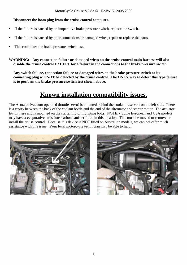
The Actuator (vacuum operated throttle servo) is mounted behind the coolant reservoir on the left side. There is a cavity between the back of the coolant bottle and the end of the alternator and starter motor. The actuator fits in there and is mounted on the starter motor mounting bolts. NOTE: - Some European and USA models may have a evaporative emissions carbon canister fitted in this location. This must be moved or removed to install the cruise control. Because this device is NOT fitted on Australian models, we can not offer much assistance with this issue. Your local motorcycle technician may be able to help.

Motorcycle
Electronic Cruise Control Installation Manual ©
(Sections 6 & 7)
Refer to the Information Setup & Operation Manual for Sections 1~5 & 8~12
For BMW K1200S
2006 model year
10 March 2009
MotorCycle Cruise Controls
MotorCycle Setup Pty. Ltd. A.B.N. 94 798 167 654
6 Kingston Street Mount Waverley, Victoria, 3149
AUSTRALIA
Mycleruise
Cotor

MotorCycle Cruise V2.83 © - BMW K1200S 2006
1
BMW K1200S Parts list for MCS 4400 kit Item Qty Part Number Description 1 1 MCSU 400C Computer 2 3 Foam mounting tape - 8cm long
MCS 4402 Vacuum actuator assembly
3 1 MCS 574 Vacuum actuator 4 1 MCS 4402A Actuator bracket
3 6g x 3/8” self tap screw MCS 4407 Vacuum hose assembly
5 1 MCS 032 Vacuum stop valve 6 1 MCS 025K Vacuum ‘T’ connector 7 4mm Vacuum hose
MCS 4404 Switch assembly
8 1 MCS 820 Control Switch 9 1 MCS 830P Switch bracket (MCS 4404A)
4 4 gauge x 1/2” stainless steel pan head self tap screw 1 100mm cable tie
10 1 M5 x 35 socket head cap screw 11 7 5mm flat washer
12 1 MCS 4401 Wiring loom
a Computer plug (26 pin) b Fuse holder (3 amp fuse) c Tach sensor connector (yellow wire) c1 MCS 4401 C Tach sensor pigtail (yellow wire) d Speed sensor (co-axial wire) e Actuator plug (4 pin) f Brake sensor connector (grey wire) g Hydraulic brake switch plug (2 pin orange and grey wires) h Power connector (orange wire) h 1 1 MCS 4401 H Power connector pigtail (orange wire) i Ground connector (black wire) j Control switch plug (6 pin)
13 1 MCS 558 Banjo bolt pressure switch (M10 x 1 thread) 14 2 10mm sealing washers
15 MCS 4405 Cable Interface Unit (CIU) assembly 16 1 MCS 4405A CIU housing 17 1 MCS 003F Actuator spool 18 1 MCS 4406 Carburettor spool 19 1 MCS 4406A Throttle spool 20 1 MCS 003H Bush 21 1 MCS 003K End Cap 22 1 M5 x 50 bolt (pivot bolt) 23 1 5mm plated flat washer 24 1 MCS 4405B CIU mounting bracket 25 1 F 20029 M5 mounting clip 26 1 M4 x 10 pan head screw (actuator cable retainer)

MotorCycle Cruise V2.83 © - BMW K1200S 2006
2
27 1 M4 x 20 pan head screw (throttle cable retainer)
28 1 MCS 4408 Carburettor cable MCS 4403 Speed sensor assembly
29 1 MCS 4403A Speed sensor bracket 30 1 MCS 027 Speed sensor 31 3 6mm flat washer 32 1 6mm Nyloc nut 33 1 M8 x 40 socket head cap screw 34 7 8mm flat washer
5 MCS 046 4.75mm dia x 4.75mm long magnet 10 MCS 042 4.75mm dia x 1.5mm long magnet 15 100mm cable ties 15 150mm cable ties 6 300mm cable ties Terminals for splice connections 6 H 1527 Splice terminal (small single) 10cm HST3 Heat shrink tube 10cm HST6 Heat shrink tube Information, Set up and Operation Manual Operation and User Manual Installation Manual Trouble shooting guide

MotorCycle Cruise V2.83 © - BMW K1200S 2006
3
15
21
103
45
67
89
1113
12
12
bj
21
22 23
hg
i
h1
1
a
ruiseCCotor
ycleM
2
cc1
e
3
4
30
24
171819
20
26
16
13f
27
14
25
3231 31
8
d
911
SETACC
RESDEC
ONOFF
10
11
7 5 7
34
28
2933 34
6
Throttle cable spool hole marking
Carburettor cable spool hole marking

MotorCycle Cruise V2.83 © - BMW K1200S 2006
4
Electronic Cruise Control
Installation Manual ©
REFER TO THE INFORMATION, SET UP AND OPERATION MANUAL FOR INFORMATION ABOUT
THE CRUISE CONTROL, SETTING UP, CALIBRATING AND USING THE CRUISE CONTROL
The cruise control computer used has been purpose built for motorcycle applications. Testing has resulted in programming to deliver safe, reliable operation on a variety of motorcycles, from 250cc up. It is essential that you install the cruise control in accordance with the advice in the installation instructions precisely so that electrical interference does not cause the unit to behave erratically or be rendered inoperative. We strongly recommend against fitting off-the-shelf motor car cruise controls to any motorcycle! WARNING: - This cruise will function properly only if your vehicle has resistor type
(radio suppression) ignition wires (spark plug leads). The cruise control may not function properly if aftermarket SOLID CORE spark plug wires are installed. Please read Section 11, Safety Issues & Features before fitting & using the cruise control.
If, after reading these instructions, you feel you are not competent to install this kit, we strongly urge you to seek the assistance of your local dealer. NOTE: - It is recommended that on most motorcycles the fuel tank is less than 1/4 full before attempting
to fit the cruise control. The fuel tank must be lifted for most installation and can be very heavy when full of fuel.
NOTE: - If the bike is fitted with a flasher device or LED brake light globe on the brake light system this
may cause interference with the cruise control brake detection. If the cruise control will not work try disconnecting the flasher device or replacing the LED globe with a conventional globe. Contact us for ways to enable both your brake light flasher or LED brake light and the cruise control.
CONTENTS
Chapters 1 to 5 and 8 to 11 are contained in the separate Information, Set up and Operation manual.
6. PREPARING THE BIKE FOR CRUISE CONTROL INSTALLATION 7. INSTALLATION

MotorCycle Cruise V2.83 © - BMW K1200S 2006
5
This manual contains several cautions, warnings and notes, which are prominently displayed. The convention used is: A warning applies whenever injury could result from ignoring the warning; A caution applies whenever damage to the bike or cruise control could result from ignoring the caution; and A note applies where other aspects should be considered before any action to do with installation is undertaken. EXAMPLES: WARNING: - Always ensure the bike is properly supported on the side or centre stand and cannot
accidentally fall off either stand.
CAUTION: - Before drilling any holes, make sure there are no components that may be damaged on the other side of the surface being drilled. Double check for any wiring harness that might be easily damaged by a drill bit.
NOTE: - Lay the wiring harness in place and connect the components before cable tying the harness in place.
PARTS LIST Check that all components depicted in the parts list of this manual are included in the cruise control kit. Please phone (03) 9808 2804 within Australia, international (61 3) 9808 2804, fax (61 3) 9808 2445 or e-mail [email protected] for advice, if any parts are missing; 6. PREPARING THE BIKE FOR CRUISE CONTROL INSTALLATION The following directions may be used to prepare the bike for cruise installation:
Seat. Use the key to release the seat lock and remove the seat.
Fairing panels. The fairing panels are mounted with several screws of varying lengths. Take careful note of the hole locations for each length screw.
MotorCycle Cruise V2.83 © - BMW K1200S 2006
6
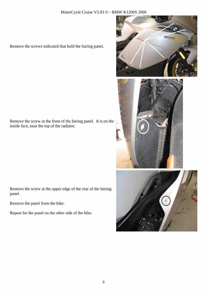
Remove the screws indicated that hold the fairing panel.
Remove the screw at the front of the fairing panel. It is on the inside face, near the top of the radiator.
Remove the screw at the upper edge of the rear of the fairing panel. Remove the panel from the bike. Repeat for the panel on the other side of the bike.

MotorCycle Cruise V2.83 © - BMW K1200S 2006
7
Upper fuel tank/battery access cover. Remove the 2 screws and lift up the battery access cover.
If a Sat/Nav is fitted to the bike, disconnect the wires for the unit at the plug under the cover. Remove the cover.
Fuel tank side cover panels. Remove the screws holding the panels.
Lift the panel and disengage the tabs shown.

MotorCycle Cruise V2.83 © - BMW K1200S 2006
8
Pull the panel to the rear to release the front corner from the grommet. Remove the panel. Remove the panel on the other side of the fuel tank.
Battery disconnection. Disconnect the cable from the negative battery terminal. Ensure that the cable cannot touch the battery terminal.
Fuel tank. Undo and remove the two mounting bolts and bosses at the rear of the fuel tank.
Disconnect the hose on the top of the tank.
MotorCycle Cruise V2.83 © - BMW K1200S 2006
9
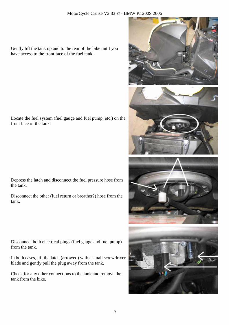
Gently lift the tank up and to the rear of the bike until you have access to the front face of the fuel tank.
Locate the fuel system (fuel gauge and fuel pump, etc.) on the front face of the tank.
Depress the latch and disconnect the fuel pressure hose from the tank. Disconnect the other (fuel return or breather?) hose from the tank.
Disconnect both electrical plugs (fuel gauge and fuel pump) from the tank. In both cases, lift the latch (arrowed) with a small screwdriver blade and gently pull the plug away from the tank. Check for any other connections to the tank and remove the tank from the bike.

MotorCycle Cruise V2.83 © - BMW K1200S 2006
10
Air inlet snorkels. Remove the air inlet snorkels from the bike. Release the two wedges to release the snorkel and air filter element (see next photo) and release the mount near the front of the snorkel.
Press the tab and slide the wedges out, then pull the snorkel and air filter element out of the air filter housing. Repeat on the other side snorkel.
Disconnect the throttle cable from the throttle bodies. Back off the adjuster at the throttle grip end of the throttle cable all the way to give as much free play as possible.
The throttle cable is shown routed on the right side of the bike, beside the frame and under the air filter housing.

MotorCycle Cruise V2.83 © - BMW K1200S 2006
11
Remove the rubber strap and the cable tie holding the throttle cable.
The throttle cable is connected to the throttle bodies between the two right side cylinders (arrowed).
Use the twist grip to apply full throttle. Insert a screwdriver or other similar device as shown to hold the throttle spindle in the full throttle position. See the next photo for more detail.
MotorCycle Cruise V2.83 © - BMW K1200S 2006
12
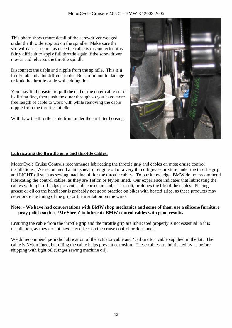
This photo shows more detail of the screwdriver wedged under the throttle stop tab on the spindle. Make sure the screwdriver is secure, as once the cable is disconnected it is fairly difficult to apply full throttle again if the screwdriver moves and releases the throttle spindle. Disconnect the cable and nipple from the spindle. This is a fiddly job and a bit difficult to do. Be careful not to damage or kink the throttle cable while doing this. You may find it easier to pull the end of the outer cable out of its fitting first, then push the outer through so you have more free length of cable to work with while removing the cable nipple from the throttle spindle. Withdraw the throttle cable from under the air filter housing.
Lubricating the throttle grip and throttle cables. MotorCycle Cruise Controls recommends lubricating the throttle grip and cables on most cruise control installations. We recommend a thin smear of engine oil or a very thin oil/grease mixture under the throttle grip and LIGHT oil such as sewing machine oil for the throttle cables. To our knowledge, BMW do not recommend lubricating the control cables, as they are Teflon or Nylon lined. Our experience indicates that lubricating the cables with light oil helps prevent cable corrosion and, as a result, prolongs the life of the cables. Placing grease or oil on the handlebar is probably not good practice on bikes with heated grips, as these products may deteriorate the lining of the grip or the insulation on the wires. Note: - We have had conversations with BMW shop mechanics and some of them use a silicone furniture
spray polish such as ‘Mr Sheen’ to lubricate BMW control cables with good results. Ensuring the cable from the throttle grip and the throttle grip are lubricated properly is not essential in this installation, as they do not have any effect on the cruise control performance. We do recommend periodic lubrication of the actuator cable and ‘carburettor’ cable supplied in the kit. The cable is Nylon lined, but oiling the cable helps prevent corrosion. These cables are lubricated by us before shipping with light oil (Singer sewing machine oil).

MotorCycle Cruise V2.83 © - BMW K1200S 2006
13
Remove the screw for the throttle grip cable cover and remove the cover.
Disconnect the cable nipple from the twist grip.
Unscrew the cable elbow fitting from the twist grip housing and withdraw the cable.
Unscrew the adjuster and run suitable lubricant (sewing machine oil or similar) down the cable.

MotorCycle Cruise V2.83 © - BMW K1200S 2006
14
Re-assemble the elbow/adjuster and run a little oil down the liner in the elbow.
Because most of these bikes have heated grips, it is probably not a good idea to put engine oil on the handlebar where the grip rotates. We have used silicone spray (spray some on to the handlebar at the end of the twist grip – arrowed) to good effect to improve the ‘feel’ of the twist grip action. Re-fit the cable and re-assemble the twist grip housing.
7. INSTALLATION
Installing the ‘carburettor’ cable Locate the new ‘carburettor’ cable in the kit. Insert the end of the cable that does NOT have an adjuster with the small barrel nipple under the air filter housing to the throttle bodies.

MotorCycle Cruise V2.83 © - BMW K1200S 2006
15
Route the inner cable (the wire rope) into the slotted receptacle in the throttle bodies (at the top of the picture). Pull the outer cable through into the receptacle. Connect the cable nipple to the throttle spindle then pull on the other end of the cable to hold full throttle while you remove the screwdriver that is holding the throttle open. Check that the cable fits correctly, is inserted properly in the receptacle (top pointer), going over the small spring loaded plate (middle pointer) and is under the bar (lower pointer) and wraps around the spindle correctly.
Installing the vacuum actuator (throttle servo) The actuator fits behind the coolant reservoir on the left side of the bike.
Remove the two mounting screws for the decorative panel that holds the electrical accessory socket. Withdraw the panel and let it hang of the wires or disconnect the plug on the back of the socket.

MotorCycle Cruise V2.83 © - BMW K1200S 2006
16
Ease the coolant reservoir outwards at the rear of the bottle and disengage the mount at the front edge of the bottle.
Remove the two mounting bolts at the rear of the starter motor.
Ease the coolant reservoir outwards and insert the cable end of the actuator into the space behind the reservoir. Look at the photos on the following pages to check the routing of the actuator cable while you are installing it. It is easier to route the cable during installation that after the actuator is mounted.
Position the actuator beside the end of the alternator so the mounting bracket is positioned on top of the starter motor mount. Re-install the two starter motor mounting bolts. Check VERY carefully that none of the cables or hoses will be chafed or cut by the actuator or the mounting bracket.

MotorCycle Cruise V2.83 © - BMW K1200S 2006
17
Route the actuator cable forward and to the right behind the N0. 2 idle air hose (the hoses are numbered); Below the idle air controller (middle of the picture); Behind the No. 3 and 4 air hoses; Up to the right behind the hose at the right rear corner of the air filter housing. WARNING: - Make sure that there is NO possibility of the actuator cable interfering with the operation of the throttle spindle.
Draw the cable out to the right side of the bike between the air filter housing and the frame.
Installing the Cable Interface Unit (CIU) The cable interface unit is mounted in the front right of the bike, above the radiator cap. Disassemble the CIU noting the location of the components.
Remove the mounting bolt for the front headlight/fairing frame (circled). Remove the cable tie arrowed.

MotorCycle Cruise V2.83 © - BMW K1200S 2006
18
Fit the CIU mounting bracket on the fairing frame mounting bolt. You will have to manoeuvre it a bit to get it into position. Replace the fairing frame mounting bolt.
Replace the cable tie removed earlier. This photo also shows another view of the CIU mounting bracket.
Route the bike’s original throttle cable down the back of the fairing frame as shown. Fit a cable tie at the top (arrowed) as shown. See the next photo for a closer look at the cable tie.

MotorCycle Cruise V2.83 © - BMW K1200S 2006
19
The cable tie holding the bike’s original throttle cable.
Loosen the lock screw in the actuator cable hole. Insert the actuator into the unthreaded hole in the CIU. Push the cable into the hole so it contacts the shoulder in the hole and GENTLY tighten the lock screw on to the cable. CAUTION: - Be careful not to over-tighten the screw and crush the cable or strip the threads.
Insert the ball nipple on the actuator cable into the hole in the thin actuator spool. Place the spool in the CIU as shown. Rotate the spool clockwise as far as it will go to fully extend the actuator cable.
Locate the free end of the ‘carburettor’ cable. This end has one lock nut on the adjuster and a ball nipple on the end of the cable. Insert the cable into the threaded hole in the CIU. Check the routing of the cables from the photo.

MotorCycle Cruise V2.83 © - BMW K1200S 2006
20
Screw the adjuster all the way in to the hole. Note: - Later cables have slightly longer adjusters, so it may be necessary to screw the adjuster out slightly to fit the spool in the CIU in the next step.
Place the ball nipple on the ‘carburettor’ cable into the marked hole in carburettor spool (the spool with the roll pin). Place the spool in the CIU with the paint mark side UP so the roll pin engages in the groove in the actuator spool. Insert the bush into the two spools. Check that the actuator cable is still fully extended by noting the position of the paint mark on the actuator spool relative to the roll pin in the carburettor spool.
Insert the end of the bike’s original throttle cable into the last hole.
Place the nipple on the original throttle cable in the marked hole in the throttle spool (the small spool with the groove in the underside). Place the spool on the bush so the roll pin on the carburettor spool engages in the groove in the throttle spool. Check the positions carefully against the photo.

MotorCycle Cruise V2.83 © - BMW K1200S 2006
21
Note that the throttle cable intrudes slightly into the screw hole.
Insert the M4 x 20 screw into this hole. Screw it in until you start to feel resistance, then turn it out slightly so the throttle cable is still free to move. This will be tightened later.
Place the end cap on the CIU. Fit a flat washer to the bolt. Insert the bolt into the CIU and into the mounting bracket. Tighten gently. After the bolt has all parts seated (when you start to feel a slight increase in the effort to tighten the bolt) do the bolt up a further ½ a turn. CAUTION: - Do not over tighten the bolt. Tighten the bolt until the nut comes up firm and no more than ½ a turn more. Over tightening the bolt can compress the bush into plastic housing and cause the spools to bind.
Push the bike’s original throttle cable into the CIU firmly to ensure that it is seated. Gently tighten the retainer screw to hold the cable in position. This is to prevent the cable falling out in situations where the cruise control has a lot of throttle applied. Under these conditions the throttle cable will have a lot of free play, and the cable could fall out of the CIU and cause a throttle jam. This screw prevents this happening.

MotorCycle Cruise V2.83 © - BMW K1200S 2006
22
Force a small amount of silicone sealant into the slot to prevent dirt or water entry.
Initial adjustment of the ‘carburettor’ cable free play Check that the twist grip has a lot of free play. Screw the adjuster at the CIU end of the carb cable out until there is about 1mm free movement in the cable. This can be checked by gently pulling the cable outer out of the adjuster, either at the CIU end of the cable or at the throttle body end. NOTE: - The twist grip should still have considerable free play.
Adjusting twist grip free play Use the adjuster in the throttle cable at the twist grip to adjust the free play in the twist grip. There should be about 2mm of free movement in the twist grip. Check throttle operation at all steering positions, full left, right and straight ahead. Make sure that the throttle snaps back to idle when released at all times.
Installing the vacuum hose Locate the idle air hose for N0. 3 cylinder. Disconnect the hose from the idle air control valve on the bottom of the air box. Be careful not to break the hose barb off the idle air control valve.
MotorCycle Cruise V2.83 © - BMW K1200S 2006
23
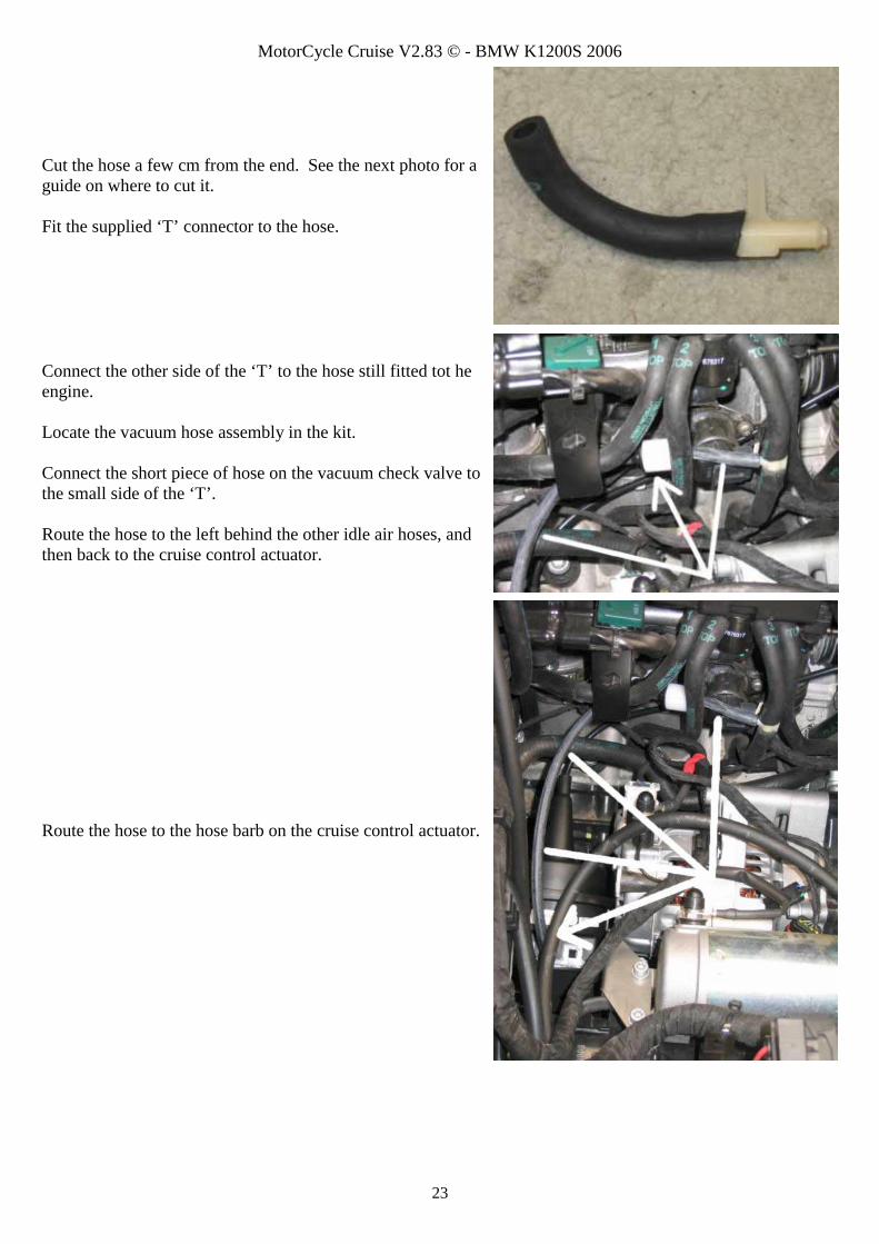
Cut the hose a few cm from the end. See the next photo for a guide on where to cut it. Fit the supplied ‘T’ connector to the hose.
Connect the other side of the ‘T’ to the hose still fitted tot he engine. Locate the vacuum hose assembly in the kit. Connect the short piece of hose on the vacuum check valve to the small side of the ‘T’. Route the hose to the left behind the other idle air hoses, and then back to the cruise control actuator.
Route the hose to the hose barb on the cruise control actuator.

MotorCycle Cruise V2.83 © - BMW K1200S 2006
24
Installing the speed sensor Undo and remove the lower mounting bolt for the right front brake calliper. Store it as it will not be re-used.
Locate the speed sensor assembly, new M8x 40 socket head cap screw and flat washers in the kit. Assemble the parts so there is one flat washer between the head of the bolt and the speed sensor bracket. Place 5 more washers on the bolt.
Place the sensor assembly on the bike as shown. Check carefully that the bracket is NOT contacting the fork leg around the bolt hose. Add an additional washer to the stack if required to ensure that the bracket does NOT contact the fork leg. Roughly align the speed sensor with the disc brake mounting bolts. NOTE: - do not tighten the bolt yet as the sensor will be removed later to connect the wires.
Locate the stack of magnets in the kit. NOTE: - you will find a set of 5 longer magnets and 10 very short magnets. Try the longer magnets first. One magnet must be placed in the head of each brake disc mounting bolt. The polarity of the magnets does not matter, but they must ALL be same polarity To achieve this, place the stack in the head of one of the front brake disc mounting bolts. Slide the stack of magnets off, leaving one magnet in the bolt.

MotorCycle Cruise V2.83 © - BMW K1200S 2006
25
Place the rest of the magnets in the bolts using the same method, without turning the stack of magnets around. This will ensure that they all have the same pole facing out
CAUTION: - Check that the magnets will not contact the fork leg or any other hardware during wheel rotation. If they do, remove the long magnets and replace them with 2 (two) of the shorter magnets in each bolt. Check the gap between the head of the sensor and the magnets. The gap should be more than 1mm to prevent the risk of damage, and less than 3mm to ensure that the cruise control will work at lower speeds. Bend the sensor bracket if required to adjust the gap
Installing the banjo bolt front brake pressure switch Cover the area below the brake union bolt with a cloth to prevent brake fluid contacting any parts. Brake fluid is corrosive to most paint finishes. Loosen and remove the banjo bolt brake line fitting that mounts the flexible brake hose to the master cylinder. Be careful not to operate the brake lever. Refit the brake hose with the new banjo bolt pressure switch provided in the kit. Use the new sealing washers also provided in the kit. Refer to your workshop manual for appropriate bolt tightening torque.

MotorCycle Cruise V2.83 © - BMW K1200S 2006
26
Detail of the banjo bolt switch after fitment.
WARNING: - The front brake circuit should now be bled to ensure that any air is purged from the brake circuit. Refer to your BMW workshop manual to facilitate this operation. In practice we have found that very gentle and careful repeated operation of the front brake lever, using only the first part of the lever travel, will effectively bleed any air back up into the brake fluid master cylinder and even into the reservoir. You can then ‘crack’ open the bleed nipple on the master cylinder to bleed out the last of the air without any significant fluid loss.
Route the wires from the banjo bolt switch as shown.
Installing the control switch Undo and remove the clutch lever assembly mounting bolt that his closest to the clutch lever. Store the bolt as it will not be re-used.

MotorCycle Cruise V2.83 © - BMW K1200S 2006
27
Use the M5 x 35 socket head cap screw and washers from the kit. Use 1 flat washer above the switch bracket. Use six (6) flat washers below the bracket.
5mm flat washer
5mm flat washers6 required
M5 x 35 cap screw
SETACC
RESDEC
ONOFF
Place the cruise control switch on the clutch lever clamp and tighten the bolt to hold the switch and clamp the clutch lever assembly to the handlebar.
Route the control switch wire around the fluid reservoir, then down the handle bar and to the rear with the bike’s other wires and cables.

MotorCycle Cruise V2.83 © - BMW K1200S 2006
28
Route the control switch wire inside the fairing frame above the steering damper, then down on the left side in front of the air filter housing. Leave the control switch wire for the moment. It will be routed and connected later.
Installing the computer (electronic module) On ‘our’ bike, there was sufficient room to mount the cruise control computer (electronic module) with the bike’s electronics module on the left side of the bike at the front. While this is probably a good logical location, we were hesitant to mount it here because the rubber straps holding the modules to the bike do not look very strong. You may decide to mount the computer here, particularly with additional cable ties to hold it, but we did not.
We did mount the computer directly behind this area, directly to the frame. The wiring loom is suitable for either location.
MotorCycle Cruise V2.83 © - BMW K1200S 2006
29
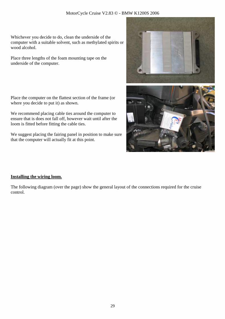
Whichever you decide to do, clean the underside of the computer with a suitable solvent, such as methylated spirits or wood alcohol. Place three lengths of the foam mounting tape on the underside of the computer.
Place the computer on the flattest section of the frame (or where you decide to put it) as shown. We recommend placing cable ties around the computer to ensure that is does not fall off, however wait until after the loom is fitted before fitting the cable ties. We suggest placing the fairing panel in position to make sure that the computer will actually fit at this point.
Installing the wiring loom. The following diagram (over the page) show the general layout of the connections required for the cruise control.

MotorCycle Cruise V2.83 © - BMW K1200S 2006
30
Tach sensor wiresuppressor resistorDO NOT R EM OVE ORCHANGE THIS SU PPR ESSOR
Cotor
Web
Site
: httt
p://w
ww
. mcc
ruis
e.co
mM
elbo
urne
, Vic
toria
, Aus
tralia
Ph +
61 3
980
8 28
04 F
ax +
61 3
980
8 24
45M
otor
Cy c
le C
ruis
e C
ontro
ls
C
Power fuse3 amp
M
Control switch
S E TA CC
RE SDE C
ONOFF
Control switchplug - 6 way
Vacuum Actuator
ruise
C omputer
ycle
Actuator plug- 4 way
Approx 40cm (16")
Banjo bolt pressure switchfitted to motorcycle's frontbrake circuitSwitch supplied with cruise kit
Orang e power wireConnect wire to accessory plug power wire
Ground wire - blackConnect to battery neg ative
Grey brake sensor wireC onnect wire to bike'sbrake l ight
Banjo bolt brakepressure switch plug
M otorcycle's brake light
Wheel speed sensor
Yellow Tach sensor wireC onnect wire to sig nalwire to ig nition coil
Two connections on the cruise control require a ‘spliced’ connection to the bike’s wiring. Power for the cruise control is sourced from a splice in the red/green 12V wire at the bike’s accessory plug. Engine speed (tach) sensing for the cruise control is sourced from a splice in one of the ignition coil wires. Two short ‘pigtail’ connectors with a spade terminal on the end (one orange and one yellow) are provided in the kit to facilitate these connections.
Fitting the orange power wire pigtail. Disconnect the plug to the accessory power socket if you have not already done so.

MotorCycle Cruise V2.83 © - BMW K1200S 2006
31
In order to gain access to a reasonable length of wire, it is helpful to disconnect this plug too.
Draw both plugs into the engine ‘bay’. Strip off as much of the cloth tape as possible from the brown and red/green wires to the accessory power plug.
Cut the red/green wire at approximately the half way point.
Strip the ends of the cut wires.

MotorCycle Cruise V2.83 © - BMW K1200S 2006
32
Follow the diagrams to make up the spliced connection. Strip and fold over the end of the orange wire to increase the conductor size to match that of the red/green wire.
The completed splice joint.
Brown wire to accesory plug
Crimp other red/green wire to orange wire
T wo spl ice terminals(cut two terminals from supplied strip of term inals)
Crimp orange pigtai l wi re to red/green wire
3cm of 3mm heat shrink tube& 3cm of 6mm heat shrink tube
Orange pigtai l from cruise control ki t
Strip end of pigtai l 4 times longer than usualFold over to provide greater conductor size
Red/green wire to accessory plugCut wire about 50mm fromplug and strip ends
Slide heat shrink over jo in andapply heat to shrink
MotorCycle Cruise V2.83 © - BMW K1200S 2006
33
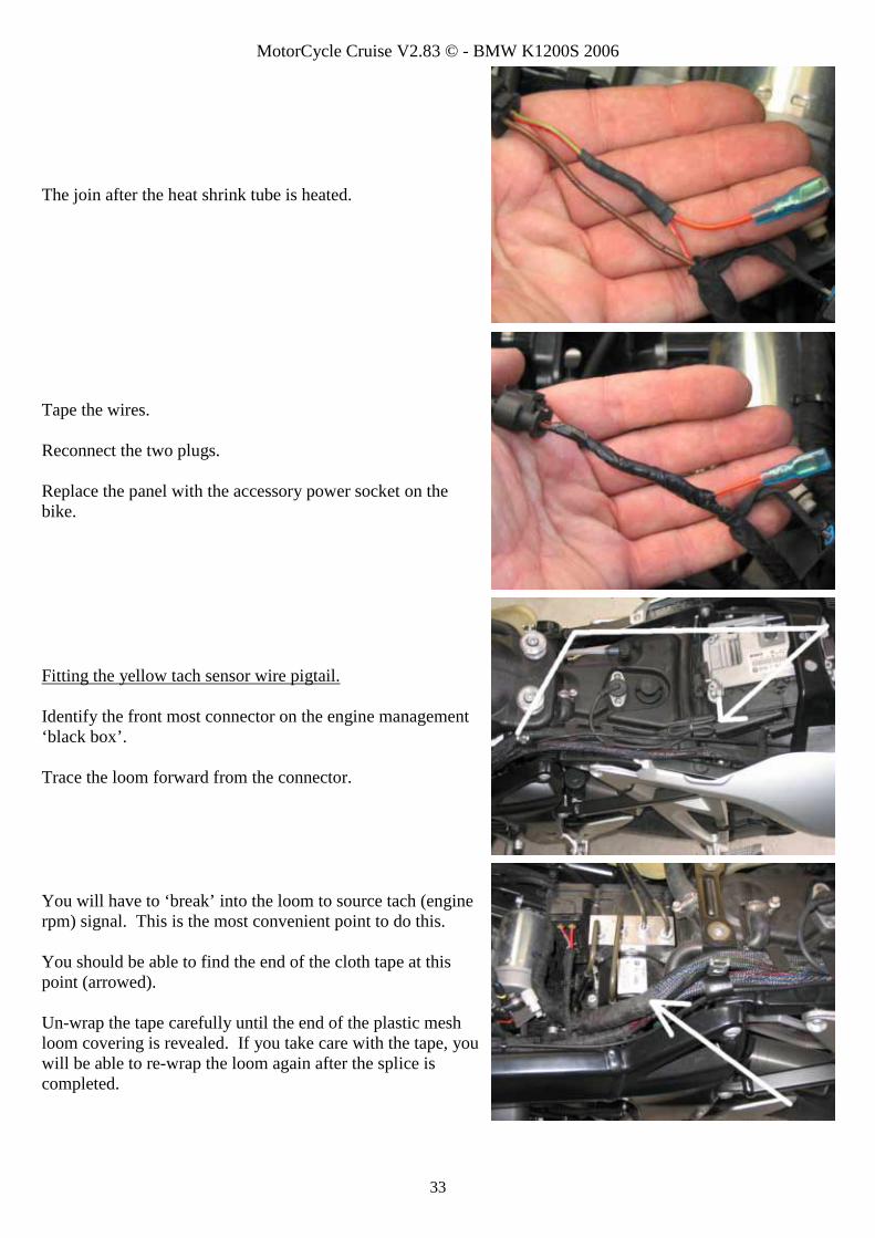
The join after the heat shrink tube is heated.
Tape the wires. Reconnect the two plugs. Replace the panel with the accessory power socket on the bike.
Fitting the yellow tach sensor wire pigtail. Identify the front most connector on the engine management ‘black box’. Trace the loom forward from the connector.
You will have to ‘break’ into the loom to source tach (engine rpm) signal. This is the most convenient point to do this. You should be able to find the end of the cloth tape at this point (arrowed). Un-wrap the tape carefully until the end of the plastic mesh loom covering is revealed. If you take care with the tape, you will be able to re-wrap the loom again after the splice is completed.

MotorCycle Cruise V2.83 © - BMW K1200S 2006
34
After pulling the mesh back to reveal about 10cm of loom, locate the black/red ignition wire (black with a red trace or stripe). This wire is the ignition signal wire to the ignition coils.
Cut this wire at about the mid point so that you have about 5cm (2”) of wire available in both directions.
Strip the ends of the wires. Place a 3cm length of each size of heat shrink tube over one wire (the one towards the back of the bike).
Follow the diagrams to make up the spliced connection. Strip and fold over the end of the orange wire to increase the conductor size to match that of the red/green wire.
Black/red wire from engine management computerCut wire and strip ends
3cm (1 1/4") of 3mm heat shrink tube
3cm (1 1/4") of 6mm heat shrink tube
Two spl ice terminals(cut two terminals from suppl ied strip of terminals)
Crimp yellow wire to black/red wire
Yel low pigtai l fromcruise control kitStrip end at least twice as long a normal
MotorCycle Cruise V2.83 © - BMW K1200S 2006
35
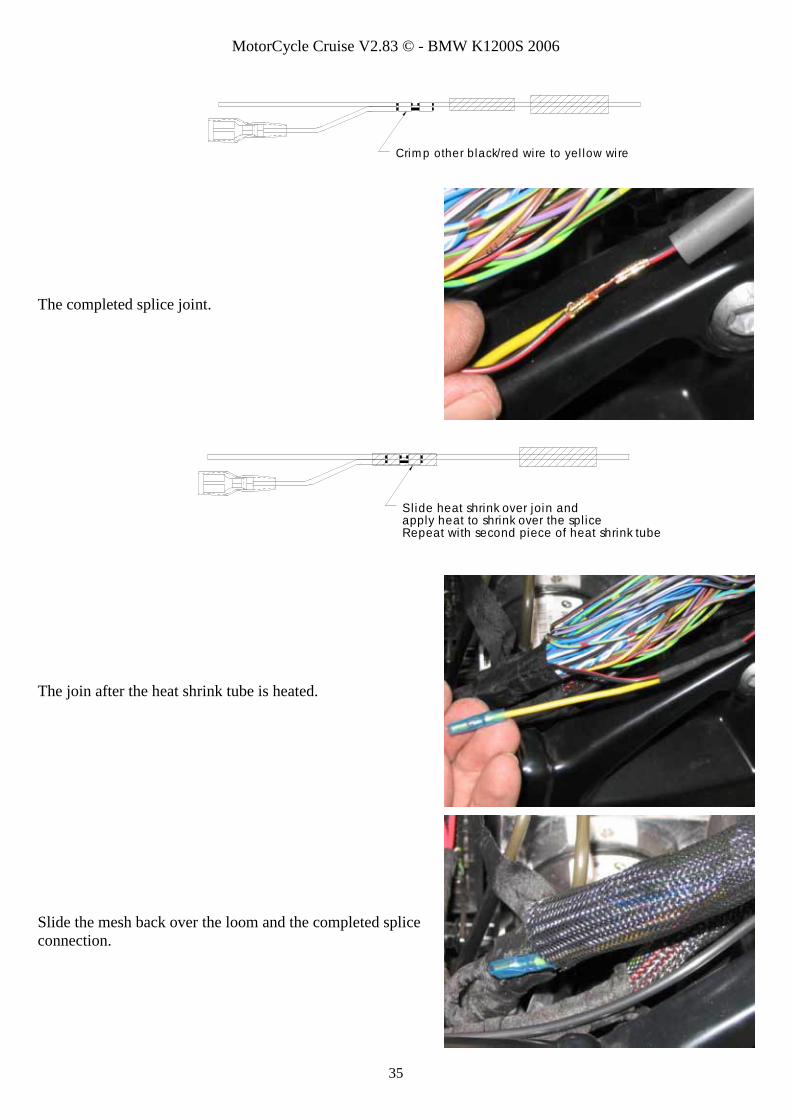
The completed splice joint.
The join after the heat shrink tube is heated.
Slide the mesh back over the loom and the completed splice connection.
Slide heat shrink over join andapply heat to shrink over the spl iceRepeat with second piece of heat shrink tube
Crim p other black/red wire to yel low wi re
MotorCycle Cruise V2.83 © - BMW K1200S 2006
36
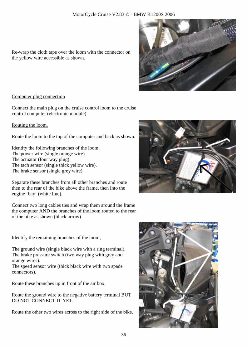
Re-wrap the cloth tape over the loom with the connector on the yellow wire accessible as shown.
Computer plug connection Connect the main plug on the cruise control loom to the cruise control computer (electronic module). Routing the loom. Route the loom to the top of the computer and back as shown. Identity the following branches of the loom; The power wire (single orange wire). The actuator (four way plug). The tach sensor (single thick yellow wire). The brake sensor (single grey wire). Separate these branches from all other branches and route then to the rear of the bike above the frame, then into the engine ‘bay’ (white line). Connect two long cables ties and wrap them around the frame the computer AND the branches of the loom routed to the rear of the bike as shown (black arrow).
Identify the remaining branches of the loom; The ground wire (single black wire with a ring terminal). The brake pressure switch (two way plug with grey and orange wires). The speed sensor wire (thick black wire with two spade connectors). Route these branches up in front of the air box. Route the ground wire to the negative battery terminal BUT DO NOT CONNECT IT YET. Route the other two wires across to the right side of the bike.

MotorCycle Cruise V2.83 © - BMW K1200S 2006
37
Control switch connection. Locate the wires from the cruise control switch that was fitted earlier. Form a loop in the wires and feed them through the cable ties that mount the computer to the frame. Connect the plug to the matching plug on the cruise loom (arrowed).
Fit a cable tie and bundle the switch wires as shown.
Route the brake pressure switch wire and the speed sensor wire across to the right side of the bike in front of the air box. Route the wires down on the left side. Route the brake pressure with wires to the connecting plug on the banjo bolt pressure with fitted earlier (white arrow), Route the speed sensor wire down and forward (black arrow). More detail of this is provided over the page.

MotorCycle Cruise V2.83 © - BMW K1200S 2006
38
Brake pressure switch connection. Connect the pressure with plug to the matching connector on the plug from the banjo bolt switch. Check VERY carefully that the wire will not be damaged by moving parts of the suspension or steering and steering damper at the front of the bike (arrowed). Fit cable ties where necessary.
Speed sensor connection Route the speed sensor wire forward inside the fairing frame and down with the front brake hose.
Route the speed sensor wire down the front brake hose.

MotorCycle Cruise V2.83 © - BMW K1200S 2006
39
Continue routing the wire down to the right side brake calliper, then behind the brake calliper mount to the speed sensor.
Loosen the brake calliper mounting bolt and dismount the speed sensor and bracket. Connect the speed sensor wires to the speed sensor. It does not matter which wire goes to which terminal.
Re-mount the speed sensor and tighten the brake calliper mounting bolt. Refer to the owner’s manual or your dealer for bolt tightening torque. Fit a cable tie to the speed sensor wire (arrowed). Fit cable ties at regular intervals along the brake hose and speed sensor wire. Re-check the speed sensor to magnet gap (1~3mm) and adjust if necessary.

MotorCycle Cruise V2.83 © - BMW K1200S 2006
40
Actuator and power connection. Route the actuator (four way plug) and power (orange wire) branches into the ‘engine bay’ with the bike’s main loom. Connect the actuator plug to the actuator. Connect the power wire to the orange pigtail wire fitted to the back of the accessory plug. Route the tach and brake sensor wires to the rear of the bike with the bike’s main loom.
Tach sensor connection. Route the yellow tach sensor wire to the yellow pigtail wire fitted earlier. Connect the wires.
Brake sensor connection. Undo the single screw on top of the brake/tail light.
Slide the light assembly to the rear to disengage the two mounting ‘prongs’. Remove the globe holder from the tail light.
MotorCycle Cruise V2.83 © - BMW K1200S 2006
41
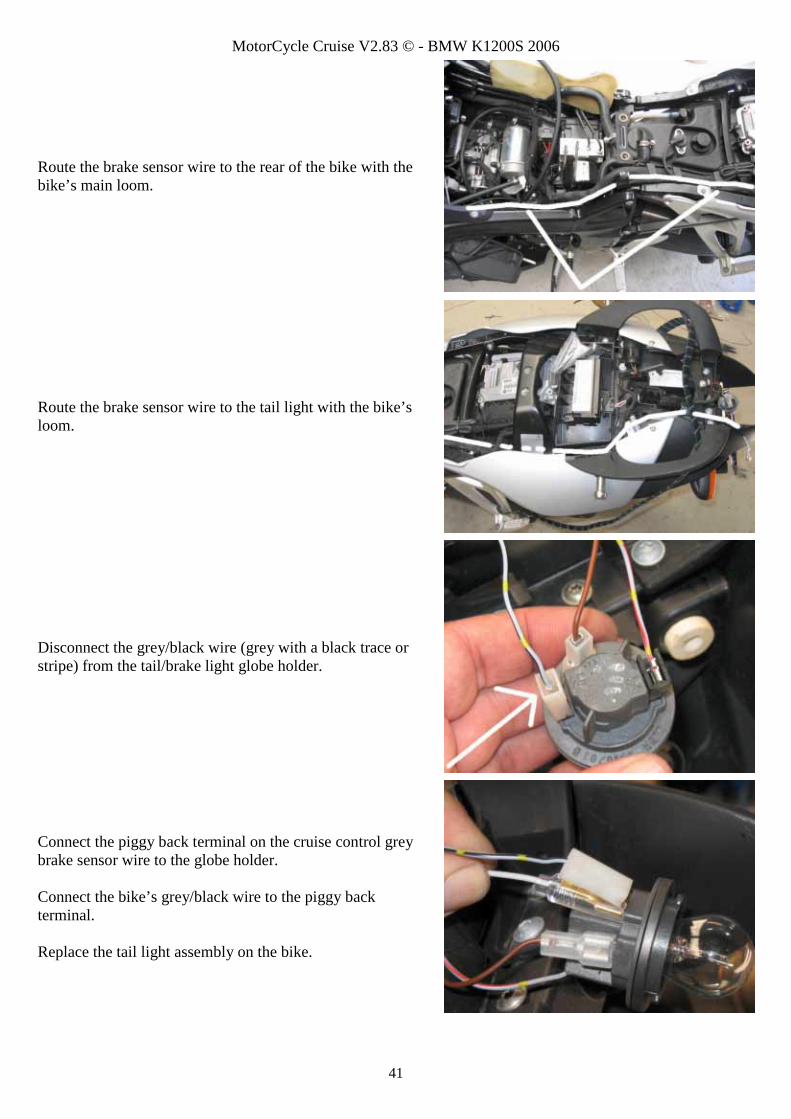
Route the brake sensor wire to the rear of the bike with the bike’s main loom.
Route the brake sensor wire to the tail light with the bike’s loom.
Disconnect the grey/black wire (grey with a black trace or stripe) from the tail/brake light globe holder.
Connect the piggy back terminal on the cruise control grey brake sensor wire to the globe holder. Connect the bike’s grey/black wire to the piggy back terminal. Replace the tail light assembly on the bike.

MotorCycle Cruise V2.83 © - BMW K1200S 2006
42
This completes the wiring loom installation apart from the ground connection which will be done after the fuel tank is replaced. Finishing up Check the routing of the wires and cables and fit cable ties where necessary. Check carefully for moving or stationary object that might damage any wires, cables or hoses. Check that all wiring connections are complete and any cable and hose connections are secure. CAUTON: Take extra care to ensure that all wires and cables will not be chafed or damaged when the
fuel tank is fitted to the bike. Replace the fuel tank on the bike reversing the removal process. Ground connection. Connect the main battery cable and the cruise control ground wire (single black wire) to the negative terminal on the battery. Re-fit the air filters and air inlet snorkels on both sides of the bike.
Carefully check that all connections are complete and the fuel tank is fitted correctly.

MotorCycle Cruise V2.83 © - BMW K1200S 2006
43
Carburettor cable final adjustment Start the engine and allow it to reach an operating temperature where the fuel injection fast idle control is off. This usually only takes a couple of minutes running time. Make sure that you have free play in the twist grip. Screw the adjuster at the CIU end of the ‘carburettor’ cable (arrowed) out SLOWLY until the engine idle speed just starts to increase. Check that the twist grip still has free play. Move the adjuster in the throttle cable at the twist grip to restore free play if there is none and repeat the above procedure on the ‘carburettor’ cable. Screw the adjuster on the carburettor cable back in ½ to 1 turn. This will give 0.5~1.0mm of free play in the cable. This sets the free play between the throttles and the cruise control actuator. Rev the engine a few times to check that it does return to idle properly each time the throttle is released. GENTLY tighten the lock nut on the adjuster. CAUTION: - The adjuster is made of brass and WILL break if over tightened. This type of damage will NOT be covered by warranty. Check and adjust the free play at the twist grip. There must be some free play to prevent the idle elevating. Check the throttle operation in all handlebar positions with engine off and engine running to ensure that handlebar movement does not cause binding or that the idle speed does not elevate. Your cruise control is now ready for testing! 8. DIAGNOSTIC MODE OPERATION Refer to Chapter 8, Diagnostic Mode Operation, in the Information, Set Up and Operation Manual. We suggest that you re-assemble the bike AFTER the diagnostic test is complete.