packet delay analysis of the advanced infrared (air) csma/ca mac
TRANSCRIPT

INTERNATIONAL JOURNAL OF COMMUNICATION SYSTEMSInt. J. Commun. Syst. 2005; 18:307–331Published online in Wiley InterScience (www.interscience.wiley.com). DOI: 10.1002/dac.705
Packet delay analysis of the advanced infrared (AIr) CSMA/CAMAC protocol in optical wireless LANs
P. Chatzimisiosn,y,z and A. C. Boucouvalas}
Multimedia Communications Research Group, School of Design, Engineering and Computing,
Bournemouth University, Fern Barrow, Poole, BH12 5BB, U.K.
SUMMARY
During the past few years the wireless technology market has experienced a tremendous growth. Userstoday expect to be able to communicate and access data anytime, anywhere, using almost any portabledevice. Infrared Data Association (IrDA) addressed the requirement for indoor multipoint wirelessconnectivity with the development of the advanced infrared (AIr) protocol stack utilizing the infraredspectrum. AIr medium access control (MAC) protocol employs a carrier sensing multiple access withcollision avoidance (CSMA/CA) protocol in addition to a request to send/clear to send (RTS/CTS) packetexchange reservation scheme and a linear adjustment of the contention window (CW). This paper developsa new modelling approach to evaluate saturation performance of the AIr protocol based on conditionalprobability arguments rather than bi-dimensional Markov chains. Moreover, we extend performancestudies in former literature papers by providing an intuitive AIr packet delay analysis assuming error-freetransmissions and a fixed number of stations. Using OPNET simulation results, we validate ourmathematical analysis and we show that the proposed model predicts AIr packet delay performance veryaccurately. Utilizing the derived mathematical analysis, we determine the significance of both link layer andphysical parameters, such as burst size, minimum CW size value and minimum turnaround time on AIrpacket delay performance. Finally, we propose suitable values for both backoff and protocol parametersthat reduce average packet delay and, thus, maximize performance. Copyright # 2005 John Wiley & Sons,Ltd.
KEY WORDS: wireless LANs; CSMA/CA; optical wireless; IrDA; packet delay; performance evaluation
1. INTRODUCTION
Recent advances in technology have made it possible to include computing and networkingtechnology into many devices such as mobile phones, laptop computers, printers, digitalcameras or PDAs. A large number of new devices (over 40 million) are manufactured every yearemploying infrared ports in order to fulfil their wireless connectivity needs [1]. Furthermore, the
Received 18 January 2004Revised 13 September 2004
Accepted 20 September 2004Copyright # 2005 John Wiley & Sons, Ltd.
yE-mail: [email protected]: [email protected]
nCorrespondence to: P. Chatzimisios, Multimedia Communications Research Group, School of Design, Engineering andComputing, Bournemouth University, Fern Barrow, Poole, BH12 5BB, U.K.
}E-mail: [email protected]

growing number of laptop computers in the market today leads to an increasing demand forfreedom from wired networks and for wireless LAN connectivity [2]. Infrared Data Association(IrDA) was established in 1993 by an industry-based group of over 150 leading companiesaiming to develop and promote communication standards especially suited for low cost, shortrange, cross-platform, point-to-point communications at a wide range of speeds. The well-known IrDA 1.x platform architecture [3] provided half-duplex, line of sight links at data ratesup to 16Mbit/s [4]. The IrDA standards have been implemented on various computer platformsand became widely available on personal computers and peripherals.
The directed nature of the infrared link and the function of the IrDA 1.x protocol mean thatonly one pair of devices can be connected at a time and multiplexing must be on an applicationbasis only. To deal with the increasing wireless LAN connectivity need and to overcome severalIrDA 1.x protocol limitations, such as point-to-point and range restrictions, IrDA proposed anew standard for indoor wireless LANs called advanced infrared (AIr). The idea of the AIrprotocol is to allow a pool of wireless users to share the infrared medium by employing asuitable medium access control (MAC) protocol. This is achieved by lifting the restrictionsexisted in the IrDA 1.x physical layer; IrLAP, the IrDA 1.x data link layer [5], is divided intothree sub-layers consisting of the AIr-MAC layer [6], which controls access to the medium andavoids packet collisions, the AIr link management (AIr-LM) layer [7], which providesmultiplexing for different client protocols and the AIr link control (AIr-LC) layer [8], whichprovides reliable data transfer and supports connections between multiple devices.
The new introduced physical layer, AIr PHY [9], is developed employing line of sight infraredports operating at a wide-angle of �608 [1, 10]. AIr PHY uses a four-slot pulse positionmodulation with variable repetition encoding (4PPM/VR) format with a base data rate of4Mbit/s. Transmission rate varies from 256 kbit/s to 4Mbit/s, trading speed for range. Variablerepetition encoding introduces redundancy used to improve signal-to-noise (SNR) ratio; betterSNR provides additional transmission range [11, 12]. Long-range AIr transceivers provide aneffective range of 3.8m at 4Mbit/s and an effective range greater than 7.6m at 256 kbit/s.
AIr MAC co-ordinates access to the infrared medium by employing carrier sense multipleaccess with collision avoidance (CSMA/CA) techniques. AIr MAC provides reliable andunreliable transfer modes as well as unreserved and reserved media access. In reserved mediaaccess, a contending station reserves the infrared channel by using a request to send/clear tosend (RTS/CTS) packet exchange and transmits a burst of data packets. The RTS/CTSexchange using the robust header of AIr packets effectively deals with the ‘hidden node’ problemcommon in wireless networks [13]. AIr MAC defines a long collision avoidance slot (CAS) timeperiod ðsÞ that includes the beginning of the CTS packet to avoid collisions caused from stationshidden from the transmitter that are not able to receive the RTS packet. Collision avoidanceprocedures are employed in an effort to minimize collisions; a contending station first selects anumber of CAS to defer transmission before attempting to reserve the media. This number israndomly selected in the range ½0;W � 1�; where W is the current contention window (CW) size.Each station adjusts its current CW value based on the experienced collisions and successfulreservations according to a linear CW adjustment. The AIr MAC protocol acts in a very similarmanner to that of the IEEE 802.11 WLAN protocol [14] but with certain significantdissimilarities. The two main differences are that: (a) IEEE 802.11 utilizes a short time slot incontrast with AIr that makes use of a long CAS slot and (b) in IEEE 802.11 an exponentialbackoff is employed and not a linear one as in AIr. The performance of the 802.11 MAC hasbeen analysed by various authors using both simulation [15] and analytical methods [16–19].
Copyright # 2005 John Wiley & Sons, Ltd. Int. J. Commun. Syst. 2005; 18:307–331
P. CHATZIMISIOS AND A. C. BOUCOUVALAS308

Although several papers in the literature [20–23] have attempted to study the AIrperformance, none deals with the delay of a transmitted packet using the AIr protocol. Infact, the throughput performance of AIr MAC’s unreserved transfer mode is presented inReference [20] by using simulation techniques. Performance evaluation of reserved transfermodes by simulation is examined in Reference [21] and the fair access of the infrared medium byall contending stations is presented in Reference [22]. An analytical model utilizing a bi-dimensional Markov chain is derived in Reference [23] to calculate AIr throughput performanceof unreserved and reserved transfer modes.
This paper presents an alternative and simpler derivation of the AIr performance analysispreviously based on a bi-dimensional Markov chain model. The new derivation is based onelementary conditional probability arguments and is more elegant than the original one inReference [23], since it clearly separates the backoff stage updating process from the backoffcounter update [19]; the new approach can be applied to any CSMA/CA MAC protocol. Wealso extend the performance analysis presented in Reference [23] to calculate the average packetdelay for the AIr protocol by deriving simple mathematical equations. As in Reference [23], thekey approximation of our model is the assumption that a reservation attempt collides with aconstant probability, which is independent of the number of collisions and successfulreservations the station has experienced in the past.} By comparing analytical with simulationresults we present evidence that our model provides extremely accurate results for AIr packetdelay performance. Utilizing the proposed analysis, we present an extensive AIr packet delayevaluation by taking into account all the factors and parameters that affect protocolperformance. Finally, we propose suitable values for both backoff and protocol parametersthat reduce average packet delay and, thus, maximize performance.
The rest of the paper is organized as follows. Section 2 provides an overview of the AIr MACfocusing on the collision avoidance procedures of the protocol. Section 3 presents theassumptions and protocol parameters utilized in our analysis. Moreover, a mathematicalanalysis is developed in order to compute the RTS packet collision and transmissionprobabilities as well as to calculate the average delay performance of packets being transmittedby the AIr protocol. Section 4 validates the proposed analysis by comparing analytical outcomewith OPNET simulation results. Section 5 employs the derived mathematical analysis andprovides an extensive performance evaluation of AIr MAC by studying the influence of thebackoff and system parameters on protocol performance. Finally, Section 6 concludes thepaper.
2. OVERVIEW OF AIR-MAC PROTOCOL
The variable repetition rate (RR) values that are supported by AIr PHY and MAC layers arepresented in Table I. The receiver monitors channel quality and advises the transmitter toimplement a suitable RR. The transmitter repeats the symbols it transmits RR times to increasethe symbol capture probability at the receiver side. RR coding is very suitable for PPM that AIrprotocol utilizes. A higher RR is used to achieve a better SNR [11, 12] as well as to reach astation that is far away from the transmitter (by trading speed for range).
}An analytical model based on the same assumptions for the exponential backoff adjustment algorithm of the IEEE802.11 protocol is presented in References [16–19].
Copyright # 2005 John Wiley & Sons, Ltd. Int. J. Commun. Syst. 2005; 18:307–331
PACKET DELAY ANALYSIS 309

AIr MAC utilizes 12 packet types in total, which are given in Table II. Two general classes aredefined; the reservation control packets (used to contend, initiate and terminate reservations)and the data transfer packets (used to transfer payload data). Figure 1 illustrates the generalformat of AIr packet. The Preamble (PA) field is transmitted for carrier sensing, symbol clocksynchronization and chip clock phase acquisition by the phase locked loop (PLL). Thesynchronization (SYNC) field qualifies the carrier detection and allows exact identification ofthe beginning of the robust header element. Both PA and SYNC fields actually allow thereceiver to detect the beginning of an incoming packet. The robust header (RH) field containsAIr PHY and AIr MAC information and is always transmitted using the maximum allowableRR encoding ðRR ¼ 16Þ to provide maximum detection sensitivity. Thus, all stations capable ofinterfering with the current transmission refrain from transmitting. The main body (MBR) fieldcontains upper layer and AIr MAC information and is transmitted using variable RR shown inTable I. MBR contains payload data and has a variable length. PA, SYNC and RH fields arepresent in all AIr MAC packet types. MBR is not present in some packet types; in this case theRH field is not protected by a CRC because it is transmitted using maximum RR ¼ 16: Whenpresent, it is followed by a cyclic redundancy check (CRC) field protecting both the RH and MBfields. The transmitter decides the suitable RR for specific transmission according to itsevaluation the link quality to the receiving station. A receiving station also recommends RRvalues to the transmitter based on its evaluation of link quality.
AIr MAC defines reliable and unreliable data transfer modes as well as reserved andunreserved media access shown in Figure 2. Unreliable transfer modes (Figures 2(a) and 2(b))guarantee the transmission of user data but not the delivery as no acknowledgement is provided
Table II. AIr MAC packet format types.
Type Description
RTS Request to send (reservation)CTS Clear to send (reservation)SOD Start of data (reservation)EOB End of burst (reservation)EOBC End of burst confirmed (reservation)UDATA Unreserved data packet (data transfer)DATA Reserved data packet (data transfer)SDATA Reserved data packet with sequencing (data transfer)ADATA Reserved data packet with acknowledgment (data transfer)ACK Acknowledgment packet (data transfer)SPOLL Sequenced poll packet (data transfer)SACK Sequenced acknowledgment (data transfer)
Table I. AIr repetition rate (RR) values.
RR Data rate
1 4 Mbit=s2 2 Mbit=s4 1 Mbit=s8 512 Kbit=s16 256 Kbit=s
Copyright # 2005 John Wiley & Sons, Ltd. Int. J. Commun. Syst. 2005; 18:307–331
P. CHATZIMISIOS AND A. C. BOUCOUVALAS310

to indicate correct packet reception. Reliable modes guarantee correct packet reception as anacknowledgement is provided for every data packet (Figure 2(c)) or for a packet burst (Figure2(d)). Unreserved data transfer mode (Figure 2(a)) transmits only one UDATA data packet to amulticast or broadcast (i.e. all devices) address using RR ¼ 16 to ensure maximum coverage.Note that the unreserved mode incurs the least overhead since does not reserve the infraredmedium by employing the RTS/CTS packet exchange and is unreliable because no acknowl-edgment is received. Reserved transfer mode with no acknowledgement (Figure 2(b)) uses theRTS/CTS reservation scheme to reserve the medium, transmits a window of DATA packets in asuccessful reservation, terminates the reservation using the EOB/EOBC packet exchange but itis still unreliable since no acknowledgement is exchanged. When one of the above two datatransfer modes is used, a MAC successful transmission indication to LM layer means that thepackets are sent and not that the packets are correctly received. Reserved transfer mode with
Preamble Sync RH CRCcontrolinformation
Main Body
sequencenumber
payload data
Packet header Robust header
64µs 40µs 32 bits 40 bits 8 bits variable length 32 bits
variable RRRR=16
Figure 1. AIr general packet format.
DATA
DATA
DATA
EOB
RTS
CTS
EOBC
Source Destination
UDATA
Source Destination
ADATA
ACK
ADATA
EOB
RTS
CTS
EOBC
Source Destination
ACK
SDATA0
SDATA1
SDATA4
EOB
RTS
CTS
EOBC 5
Source Destination
(a) (b) (c) (d)
. . . . .
... . .
Figure 2. AIr MAC transfer modes: (a) unreserved transfer mode with UDATA packet;(b) reserved transfer mode with DATA packet (no acknowledgement); (c) reservedtransfer mode with packet acknowledgement (ADATA packet); and (d) reserved
transfer mode with sequenced data (SDATA packet).
Copyright # 2005 John Wiley & Sons, Ltd. Int. J. Commun. Syst. 2005; 18:307–331
PACKET DELAY ANALYSIS 311

acknowledgement (Figure 2(c)) and reserved transfer mode with sequenced data (Figure 2(d))also employ the RTS/CTS reservation scheme and successful data reception is based on animmediate acknowledgement packet (ACK) and on a receiver’s indication in the end of burstconfirm (EOBC) packet of the next packet expected, respectively. For these two data transfermodes, a MAC successful transmission indication to LM layer means that the packets arecorrectly received. Since this work studies the performance of the reserved access reliablesequenced transfer mode (SDATA), the format definition of the AIr MAC packets used inSDATA is shown in Figure 3.
In reservation media access schemes (Figures 2(b)–2(d)), the transmitting station reserves themedium for the duration contained in the reservation time (RT) field of the RTS packet ittransmits. After a turn around time (TAT) delay, the receiving station responds with a CTSpacket and echoes the reservation period in the RT field of the CTS packet. As the RT field iscontained in RH, it is always transmitted using maximum RR ¼ 16 to ensure maximumcoverage. Thus, even stations being able to hear only the RTS or only the CTS packet defertransmission for the entire reservation period. Moreover, the RTS/CTS scheme is employed toaddress the hidden station (a station not being able to hear the transmitter or the receiver)problem [13] at the expense of the time required for transmitting the RTS and CTS packets.When the transmitter receives the CTS packet, waits for a TAT delay and initiates a windowpacket transmission. After the last data packet is transmitted and before the reservation timeexpires, the transmitter requests termination of current reservation by transmitting an end of
PA
Robust Header (RH) (RR=16)
Sync hRTS RID Type RT RR CRC variablereserved DA
PA Sync hCTS RID Type RT reserved
PA Sync hSDATA RID Type RR CRC variable reserved DA TAMGMTSADA Seq -SBL
PA Synch EOB RID Type reserved
PA Synch EOBC RID Type Seq-R RR*reserved reserved
MAC Body (MBR) MBR(RR)
numberof bits
duration (in µsec)
256 160 8 4 8 4 4 4
64 40 128
16 32
8 3216 16 8 <=16384
SDATA MBR overhead lS’ =16+16+8+8+32=80 bits
Figure 3. AIr MAC packet definitions.
Copyright # 2005 John Wiley & Sons, Ltd. Int. J. Commun. Syst. 2005; 18:307–331
P. CHATZIMISIOS AND A. C. BOUCOUVALAS312

burst (EOB) packet. The receiver waits a TAT period and confirms termination of currentreservation by responding with an EOBC packet. As with RTS/CTS exchange, a stationreceiving the EOBC or the EOB packet realizes that the current reservation is over and that it isable to contend for the medium again.
AIr MAC employs CSMA/CA techniques to minimize collision probability. A stationwishing to transmit and regardless of the transfer mode it employs, it first invokes the CAprocedures in an effort to minimize collisions with other stations. In the SDATA transfer mode,which is presented with detail in Figure 4, a contending station always invokes the CAprocedures before an RTS packet transmission. The contention period is slotted and a station isallowed to transmit only at the beginning of each slot time ðsÞ: A competing station for mediumaccess first senses the medium; if the medium is busy, it waits for the transmitting station tofinish and for the beginning of the next contention period. The contending station theninitializes its backoff counter by selecting an integer random number of CAS to defertransmission in order to minimize the collision probability with other transmissions. Thisbackoff counter is uniformly selected in the range ð0;CW� 1Þ where CW is the currentcontention window size and the backoff interval is assigned to CAS timer. The CW size valuesdepend on the number of successful reservations and collisions that the transmitting station hasexperienced in the past. If during the station’s deferral period another transmission is observed,the station freezes its CAS timer and restarts it again when the ongoing transmission is finished(the medium becomes free again) and the next contention period is started.k When the CAStimer reaches zero, the station attempts to reserve the channel by transmitting an RTS packet.While a transmitter is sending a packet, it blinds its own receiver such that it cannot receiveremote infrared pulses. The receiving station waits a minimum TAT to allow for thetransmitter’s receive circuitry to recover and responds with a CTS packet. After the successful
Source
Destination
RTS
CTS
SDATA 0 SDATA 1 SDATA 7…..
TAT EOB
EOBC 8
Other contending stations
CA Slots
CA Slots
defer contention
EX
IT2
EXIT1
TAT
CA Slots
TAT
TAT
CA Slots
CA Slots
CA Slots
Time
Time
Time
ppb
Figure 4. Reserved access scheme with sequenced transfer mode (SDATA packets).
kContention period starts a TAT period after the EOBC packet that terminates a reservation. The TAT delay is requiredbecause the station that transmitted the EOBC packet should be able to receive the next packet. Contention period endswhen a non-colliding RTS packet is transmitted.
Copyright # 2005 John Wiley & Sons, Ltd. Int. J. Commun. Syst. 2005; 18:307–331
PACKET DELAY ANALYSIS 313

RTS/CTS exchange, the transmitting station, after a TAT delay, transmits a burst of datapackets and requests termination of current reservation by transmitting a EOB packet. Thereceiving station responds with an EOBC packet confirming reservation termination. Thereservation time duration is echoed in the RT field of both the RTS and CTS packets. Thus,stations being able to hear only the RTS or only the CTS packet refrain from transmitting forthe entire reservation period.
AIr MAC also considers synchronizing all stations contending for the medium at exactly thesame time after a successful RTS/CTS medium reservation, even for stations hearing only theEOB or the EOBC packet. Synchronization is accomplished by implementing two timers(EXIT1 and EXIT2). EXIT1 time duration is defined as the TAT after the EOB plus thetransmission time of the EOBC packet plus the TAT after the EOBC packet and EXIT2 isdefined as the TAT delay (Figure 4). Moreover, a contending station, after transmitting the RTSpacket, starts the wait for CTS (WFCTS) timer. If another (one or more) stations has selectedthe same CAS slot, it transmits an RTS packet at the same time and the reservation attempt isunsuccessful. The transmitting stations determine the resulting collision by the WFCTS timerexpiration. This timer value ð5TATþ TTRHÞ expresses the amount of time a station that hastransmitted an RTS packet will wait for the corresponding CTS packet. If a valid CTS has notbeen received within the WFCTS period, the transmitter assumes that a collision occurred andcontends again for medium access by selecting a new CAS slot and re-attempting a reservation.To synchronize the colliding stations with the remaining stations, the WFCTS timer shouldexpire at the end of the current time slot. Time required for transmitting packets and packetelements as well as the timer values used in our work are summarized in Table III.
The AIr protocol defines a CAS duration, which is significantly longer than the one of similarCSMA/CA protocols in order to provide an effective solution to utilization degradation causedby collisions from hidden stations, a problem which is likely to appear in infrared LANs. Forexample, the IEEE 802.11 specification [14] defines that the CAS duration accounts for thepropagation delay, for the time needed to switch from receiving to transmitting state and for thetime needed for the physical layer to signal the channel state to the MAC layer. In AIr MAC,
Table III. AIr timer durations, packet and packet element transmission times for C ¼ 4 Mbit=s:
Packet/packet element Duration Time (ms)
TPA (packet element) 64TSYNC (packet element) 40TRH (packet element) 128TTRH (packet) TPA þ TSYNC þ TRH 232TRTS (packet) TTRH þ 48=C 244TCTS (packet) TTRH 232TEOB (packet) TTRH 232TEOBC (packet) TTRH 232TACK (packet) TTRH 232TAT 200s (CAS slot) 800EXIT1 timer TATþ TEOBC þ TAT 632EXIT2 timer TAT 200WFCTS timer s� TRTS 556
Copyright # 2005 John Wiley & Sons, Ltd. Int. J. Commun. Syst. 2005; 18:307–331
P. CHATZIMISIOS AND A. C. BOUCOUVALAS314

the CAS duration ðsÞ is defined as being greater than the transmission time of the RTS packetplus the TAT delay plus the time need to detect the beginning portion (PA and SYNC fields) ofthe responding CTS packet ðs > TRTS þ TATþ TTPA þ TTSYNCÞ: Such a long CAS durationensures that contending stations hidden from the transmitter that are not able to hear the RTSpacket transmission but not from the receiver will receive the beginning of the CTS packetwithin a single CAS duration. Thus, a longer CAS duration provides a much better hiddenstation approach at the expense of possible performance degradation if the number of emptyand colliding CAS during the contention periods is high. This number depends on the numberof the competing stations and on the CW values used by these stations.
As stations can only adjust their CW values after successful reservations and collisions, theimplemented CW adjustment algorithm becomes of great importance if maximum utilization isto be achieved. Small CW size values result in a very high collision probability and, therefore, tolow performance due to the increased number of collisions. When large CW size values areimplemented, the increased number of empty CAS will also result in low medium utilization. Astation can only estimate the suitable CW value it should implement based on the experiencedsuccessful reservations and collisions. AIr specifications define that the AIr-LM layer selects theCW value to be used in every reservation attempt and pass it down to the MAC layer. The AIr-LM layer does not provide rules for CW size adjustment but suggests guidelines by utilizing alinear algorithm for incrementing and decrementing CW after a collision and a successfulreservation attempt, respectively. This CW size adjustment can be achieved since thetransmitting station always ‘remembers’ the CW value used in the previous reservationattempt. If this attempt was successful, CW is decreased by 4; if it resulted in a collision, CW isincreased by 4. A minimum CW value of 8 (lower limit) and a maximum CW value of 256(upper limit) are also defined [7].
3. MATHEMATICAL ANALYSIS AND MODELLING
Our mathematical analysis consists of three parts. The first part presents the assumptions andthe parameters that we utilize in our analysis. The second part considers the behaviour of asingle station to compute the conditional probability p that an RTS packet experiences acollision and the stationary probability t that a station transmits an RTS packet in a randomlychosen CAS for a network of n stations. Note that both probabilities are independent of thereserved access scheme employed by the stations. Finally, in the last part, by examining theevents that can occur in a randomly chosen CAS, we derive the average delay performance ofpackets being transmitted by the AIr protocol; simple equations calculate packet delay as afunction of probabilities p and t: The key assumption used in our model is that an RTStransmission always collides with probability p regardless of the CW value used to select thedeferral period for the reservation attempt.
3.1. Analysis assumptions and parameter definitions
This work concentrates on the packet delay performance for a fixed number of stations undersaturation conditions. In saturation conditions, every station has immediately a burst of packetsready for transmission, after the completion of each successful burst transmission. In otherwords, the transmission queue for every station is always non-empty. All burst of packets are
Copyright # 2005 John Wiley & Sons, Ltd. Int. J. Commun. Syst. 2005; 18:307–331
PACKET DELAY ANALYSIS 315

considered ‘consecutive’, each one needs to wait for a random backoff time before beingtransmitted. All stations always employ the reserved transfer mode with sequenced dataalthough the analytical model can be easily altered to evaluate performance of the remainingreserved transfer modes supported by the AIr MAC (Figure 2). After a successful reservationattempt, a station transmits packets per burst (ppb) of fixed payload size of l bits at a fixed datarate of C Mbit=s: We assume ideal channel conditions meaning that a non-colliding packet isalways received error-free to all network stations. Current analysis also assumes that reservationcontrol packets (RTS, CTS, EOB and EOBC) are always transmitted error-free. This is arealistic assumption because, since control packets CTS, EOB and EOBC contain only an RHportion which is transmitted using the maximum repetition rate RR ¼ 16 to minimizetransmission errors. An RTS control packet has also an MBR field consisting of only 48 bits,which is transmitted using variable RR. This MBR length is extremely small for the expectedlink quality and the assumption that the RTS packets are always transmitted error-free alsoholds true. Moreover, since we do not consider channel bit errors, an RR increase resulting inhigher symbol capture probability at the receiver is not considered. The MB of all data packetsare always transmitted in the same RR and the RH portion is transmitted in the protocolsuggested RR value of 16. We also assume that the one-way propagation delay is very small andcan be safely neglected due to the fact that the considered indoor links operate at veryshort distances. Moreover, our analysis also assumes that there are no hidden stations. Thus,all stations will always receive the RTS and the CTS packets of a successful reservation.Therefore, there is no fairness problem as all stations have an equal chance to reserve theinfrared medium.
3.2. Calculation of the RTS transmission probability
As explained earlier, the backoff counter for every station depends on the collisions and on thesuccessful reservation attempts experienced by the station in the past. The CSMA/CA protocolprocedure specifies that before transmitting each station selects a random value for its backoffcounter in the range ð0;W � 1Þ: If the reservation attempt failed (the RTS transmissioncollided), then the AIr protocol employs the linear backoff i.e. the next backoff value will beselected in the range ½0; ðW þ 4Þ � 1� and so forth. We define for convenience W ¼ CWmin: Letm be the ‘maximum backoff stage’ defined as CWmax ¼ W þ 4m: Since a station may be in stagei 2 ½0;m�; we adopt the following notation:
Wi ¼ W þ 4i; i 2 ð0;mÞ ð1Þ
where i is defined as the backoff stage that identifies the number of retransmissions suffered byan RTS packet. According to the definition, we have W ¼ W0 ¼ CWmin and Wm ¼ CWmax: AIrstandard specifies that CWmax ¼ 256 and m ¼ 62 [7].
Let us denote with TX the event that a station is transmitting during a slot time and withPðs ¼ ijTXÞ the steady-state probability that a transmitting station is found in stage i > 0: Sincethis probability is given by the probability that the station, in the previous transmission slot, wasfound in stage i � 1 and that the transmission failed (with probability p), it follows thatPðs ¼ ijTXÞ can be calculated as
Pðs ¼ ijTXÞ ¼ cp
1� p
� �i
ð2Þ
Copyright # 2005 John Wiley & Sons, Ltd. Int. J. Commun. Syst. 2005; 18:307–331
P. CHATZIMISIOS AND A. C. BOUCOUVALAS316

where c is a constant parameter that we will derive next and p is the probability that areservation attempt fails due to a collision, when at least one of the n� 1 remaining stationstransmit an RTS packet in the same time slot. If we assume that all stations see the system atsteady state and transmit with probability t; the collision probability p is given by
p ¼ 1� ð1� tÞn�1 ð3Þ
For convenience in further calculations, we set
a ¼p
1� pð4Þ
Since a station is always found in the i stage, we have
Xmi¼0
Pðs ¼ ijTXÞ ¼ 1 ð5Þ
Substituting (2) and (4) into (5), the value of the parameter c is found as
c ¼1� a
1� amþ1¼
1� p=1� p
1� ðp=1� pÞmþ1ð6Þ
Using (4) and (6), (2) becomes:
Pðs ¼ ijTXÞ ¼ð1� 2pÞð1� pÞm
ð1� pÞmþ1 � pmþ1
p
1� p
� �i
ð7Þ
We are ultimately interested in the unconditional probability t ¼ PðTXÞ that the stationtransmits a packet in a randomly chosen slot. By utilizing Bayes’ theorem:
Pðs ¼ ijTXÞ ¼PðTXjs ¼ iÞPðs ¼ iÞ
PðTXÞð8Þ
which in turn yields, for all i values in ð0; . . . ;mÞ:
PðTXÞPðs ¼ ijTXÞPðTXjs ¼ iÞ
¼ Pðs ¼ iÞ ð9Þ
This equality yields also for the summation:
PðTXÞXmi¼0
Pðs ¼ ijTXÞPðTXjs ¼ iÞ
¼Xmi¼0
Pðs ¼ iÞ ¼ 1 ð10Þ
A reservation attempt occurs when the backoff counter of the transmitting stationbecomes equal to zero, regardless of the backoff stage. Thus, the transmission probability t isequal to
t ¼ PðTXÞ ¼1
Pmi¼0
Pðs ¼ ijTXÞPðTXjs ¼ iÞ
ð11Þ
It remains to find an expression for the conditional probability PðTXjs ¼ iÞ: This probabilitycan be calculated by dividing the average number of slots a station spends in the transmissionstate ði; 0Þ while in stage i (exactly 1 slot according to the adopted time scale), and the averagenumber of slots that a station spends in the backoff stage i which is equal to ðWi þ 1Þ=2: Sincethe average number of slot times spent for each backoff counter transition is exactly 1 slot,
Copyright # 2005 John Wiley & Sons, Ltd. Int. J. Commun. Syst. 2005; 18:307–331
PACKET DELAY ANALYSIS 317
therefore:
PðTXjs ¼ iÞ ¼1
1þ 1ðWi � 1Þ=2¼
2
Wi þ 1ð12Þ
Therefore, the probability t that a station transmits a packet in a randomly chosen slot time isequal to
t ¼1Pm
i¼0 ½ð1�2pÞð1�pÞm
ð1�pÞmþ1�pmþ1ð p1�pÞ
iWiþ12 �
¼2
ð1�2pÞð1�pÞm
ð1�pÞmþ1�pmþ1
Pmi¼0 ½ð
p1�pÞ
iðWi þ 1Þ�ð13Þ
After some algebra, Equation (12) becomes equal to**
tðpÞ : t ¼2
ðW þ 1Þ þ 4pðð1�pÞmþ1þð2mþ1Þpmþ1�ðmþ1ÞpmÞðð1�pÞmþ1�pmþ1Þð1�2pÞ
ð14Þ
Equations (3) and (14) represent a non-linear system with two unknowns p and t: This systemcan be solved by utilizing numerical methods and evaluating p and t for a certain W and mcombination. Note that p 2 ½0; 1� and t 2 ½0; 1�: As it has been shown in Reference [23]throughout a detailed proof, this non-linear system has a unique solution.
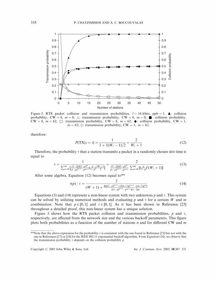
Figure 5 shows how the RTS packet collision and transmission probabilities, p and t;respectively, are affected from the network size and the various backoff parameters. This figureplots both probabilities as a function of the number of stations n and for different CW and m
0
0.1
0.2
0.3
0.4
0.5
0.6
0.7
0.8
0.9
1
0 5 10 15 20 25 30 35 40 45 50
Number of stations
Tra
nsm
issi
on p
roba
bilit
y
0
0.1
0.2
0.3
0.4
0.5
0.6
0.7
0.8
0.9
1
Col
lisio
n pr
obab
ility
Figure 5. RTS packet collision and transmission probabilities, l ¼ 16 kbits; ppb ¼ 1: m: collisionprobability, CW ¼ 8; m ¼ 0; 4: transmission probability, CW ¼ 8; m ¼ 0; &: collision probability,CW ¼ 8; m ¼ 62; &: transmission probability, CW ¼ 8; m ¼ 62; ^: collision probability, CW ¼ 1;
m ¼ 62; }: transmission probability, CW ¼ 1; m ¼ 62:
**Note that the above expression for the probability t is consistent with the one found in Reference [23] but not with theone in References [17] or [18] for the IEEE 802.11 exponential backoff algorithm. From Equation (14), we observe thatthe transmission probability t depends on the collision probability p:
Copyright # 2005 John Wiley & Sons, Ltd. Int. J. Commun. Syst. 2005; 18:307–331
P. CHATZIMISIOS AND A. C. BOUCOUVALAS318

values. When no CW size adjustment is enforced after a successful reservation or collisionðm ¼ 0Þ; the figure illustrates that the collision probability is highly dependent on the number ofstations. A large network size results in a higher collision probability and, thus, in an increasednumber of collisions. Conversely, when m ¼ 0 the probability of an RTS transmission ispractically not affected by network size. If CW size is increased or decreased after a collision or asuccessful reservation, respectively, results show that the collision probability increases asnetwork size increases for n520: Moreover, the RTS transmission probability is decreased for nvalues less than 25; for larger network size scenarios t attains roughly the same values having aslight decreasing trend.
3.3. Packet delay analysis
This section presents an elegant method to calculate the average packet delay for a successfullytransmitted packet, based on the analysis derived in the previous section. The average delayE½D� is defined to be the time interval from the time a packet is at the head of its MAC queueready for transmission, until its successful reception. The average packet delay E½D� can befound by
E½D� ¼ E½X �E½slot� ð15Þ
where E½X � is the average number of time slots needed for a successful packet transmission andE½slot� is the average length of a slot time. E½X � is calculated as
E½X � ¼1
tð1� pÞppb¼
1
tð1� tÞn�1ppbð16Þ
From Equation (15) we observe that the average packet delay depends on the average lengthof a slot time E½slot� which is still unknown and will be calculated next. Based on the calculatedRTS collision probability p and transmission probability t; and in order to compute E½slot�; wenow analyse all possible events that can occur in a randomly chosen time slot. Let Ptr be theprobability that at least one reservation attempt occurs (at least one station transmits an RTSpacket) in the considered slot. For a LAN of n stations, each transmitting with probabilityt; Ptr is given by
Ptr ¼ 1� ð1� tÞn ð17Þ
A packet collision takes place when two or more contending stations initiate simultaneouslyan RTS packet transmission attempting to reserve the infrared medium in the same slot time.The conditional probability Ps that an occurring RTS transmission is successful is given by theprobability that exactly one station transmits and the remaining n� 1 stations defertransmission, conditioned on the fact that at least one station (out of n stations) transmits anRTS packet.
Ps ¼Psuccess
Ptr¼
ntð1� tÞn�1
1� ð1� tÞnð18Þ
Therefore, a successful reservation attempt in a randomly selected slot occurs with probabilityPtrPs and the time utilized for transmitting payload information is ppb t; where ppb is thewindow size and t is defined as the time required for transmitting payload information data in
Copyright # 2005 John Wiley & Sons, Ltd. Int. J. Commun. Syst. 2005; 18:307–331
PACKET DELAY ANALYSIS 319

an SDATA packet. The value of t is given by
t ¼l
Cð19Þ
where l is the packet payload data length and C is the data rate.The average slot duration can be evaluated by considering that a random slot is empty with
probability 1� Ptr; with probability PtrPs the slot contains a successful reservation and withprobability Ptrð1� PsÞ the slot contains a collision. Thus, the average length of a slot timeE½slot� is equal to
E½slot� ¼ ð1� PtrÞsþ PtrPsTs þ Ptrð1� PsÞTc ð20Þ
where s is the duration of an empty slot time, Ts and Tc are the time durations the medium issensed busy due to a successful reservation and a collision involving two or more simultaneouspacket transmissions, respectively. A collision always lasts exactly one CAS and, therefore:
Tc ¼ s ð21Þ
Considering Equation (21), Equation (20) can be easily reduced to
E½slot� ¼ PtrPsTs þ s� PtrPss ð22Þ
For AIr networks employing the reserved transfer mode with sequenced data (SDATApacket) (Figure 2(d)), the duration of Ts is equal to
TSDATAS ¼ Dover þ ppbðtþ FS þ p1Þ ð23Þ
where Dover is the reservation overhead that includes the transmission time of the RTS, CTS,EOB and EOBC packets as well as the TAT delays that follow these packets, FS is thetransmission time of the SDATA packet overhead (preamble, robust header, CRC, etc.) and p1is the preparation time of an SDATA packet (practically equal to zero). Assuming that the RTSMBR field is always transmitted using RR ¼ 1; Dover is given by
Dover ¼ TRTS þ TATþ TCTS þ TATþ TEOB þ TATþ TEOBC þ TAT ð24Þ
The value of FS can be found as
FS ¼ TTRH þRR l0SC
ð25Þ
where l0S is the length of the MBR overhead of an SDATA packet and TRH is the transmissiontime of a packet with no MBR field (defined in Section 2). Table III gives all the packet andpacket element transmission times for C ¼ 4 Mbit=s: Finally, if we substitute Equations (16)and (22) into Equation (15), the average packet delay E½D� can be easily calculated.
Our analytical model also allows measurement of the time portion utilized on all componenttasks affecting AIr delay performance. Such an evaluation reveals the impact of physical andlink layer parameters to utilization. It is valuable for link designers in achieving high utilizationat a reasonable cost and for link implementers in selecting suitable parameter values in order tomaximize performance. Considering that a randomly selected slot is empty with probability1� Ptr and that the CAS duration is s; the time portion utilized in empty CAS because nostation transmits is given by
Tempty ¼ð1� PtrÞs
PtrPsTs þ s� PtrPssð26Þ
Copyright # 2005 John Wiley & Sons, Ltd. Int. J. Commun. Syst. 2005; 18:307–331
P. CHATZIMISIOS AND A. C. BOUCOUVALAS320

A randomly selected slot contains a collision with probability Ptrð1� PsÞ and the time portionutilized on collisions when two or more stations are simultaneously trying to reserve the infraredchannel is
Tcoll ¼Ptrð1� PsÞs
PtrPsTs þ s� PtrPssð27Þ
The time portion utilized on transmitting data packet overheads, the control packets (RTS/CTS/EOB/EOBC) and the associated TAT delays during a successful reservation period is givenby
Tover ¼PtrPsðTs � lppb=CÞPtrPsTs þ s� PtrPss
ð28Þ
As all component tasks that affect AIr delay performance are considered, the followingequation always holds true:
Tempty þ Tcoll þ Tover þU ¼ 1 ð29Þ
where U is defined as the utilization (throughput efficiency) of the link that can be found inReference [23]. Equation (29) can be easily verified from Equations (26), (27) and (28).
4. MODEL VALIDATION
In this section, we validate the previously presented analytical model by comparing analyticalwith simulation results obtained using the AIr simulator introduced in Reference [21]. Thissimulator was developed using the OPNET modeller modelling and simulation softwarepackage [24] and closely follows all timer values and packet element transmission times definedby AIr specifications. OPNET modeller is an event-driven simulator and provides a powerfulgraphical tool to display simulation statistics. OPNET uses hierarchically linked domains todenote a network design and stations are defined in the network domain, which is the top-leveldomain. Each station has a set of processes and each process can represent a layer in theprotocol stack. Moreover, a process can be defined by a finite state machine. The transmissionof packets across network links is controlled by pipeline-stage C=Cþþ coded routines and theuser can produce and add C code to be executed when entering and exiting each state. In fact,our OPNET AIr simulator emulates the real operation of a wireless station as close as possible,by implementing the collision avoidance procedures and by closely following all parameterssuch as TATs, propagation delays and packet transmission times defined by AIr specifications.
In fact, we have suitably modified the standard library of OPNET in order to employsaturation conditions, i.e. all stations always have a packet ready for transmission. After theessential modification of the simulator in order to calculate AIr packet delay performance, wehave run simulations on network sizes varying from 1 to 50 stations, in steps of 5. In allsimulation runs, we assumed ideal channel conditions; an error-free medium is assumed and nohidden stations are considered. Furthermore, the reserved transfer mode with sequenced datawas employed; stations transmit ppb SDATA packets in every successful reservation attempt.Each SDATA packet is always carrying 16 kbits of payload data (the maximum allowable size)at the 4 Mbit=s data rate.
Copyright # 2005 John Wiley & Sons, Ltd. Int. J. Commun. Syst. 2005; 18:307–331
PACKET DELAY ANALYSIS 321

Figure 6 provides packet delay performance results versus the number of stations and studiesthe accuracy of the developed mathematical analysis. The parameters used in both the analyticalmodel and the simulation runs follow the parameters summarized in Table III. The performancecomparison shows that analytical results (lines) coincide with simulation results (symbols) fordifferentW ; m and ppb values. Note that simulation results are acquired with a 95% confidenceinterval lower than 0.002. Our packet delay analysis gives results in high agreement withOPNET simulations and, therefore, it predicts very accurately AIr packet delay performance.Furthermore, an interesting observation is that packet delay significantly depends on theimplemented backoff parameters such as W ; m and ppb. The presented performance results area strong indication of the great importance for the proper selection of the backoff and protocolparameters in order to reduce packet delay and, thus, maximize performance.
5. PERFORMANCE EVALUATION
This section studies the impact of the backoff and system parameters on AIr MAC protocolperformance by employing the previously derived mathematical analysis. Figure 7 explores thedependency of performance on the CW size. Packet delay results are plotted versus number ofstations when no CW size adjustment is imposed ðm ¼ 0Þ after a successful reservation orcollision. The figure shows that packet delay is not practically affected when a large CW size isimplemented (CW ¼ 32 or 64) for any network scenario. Conversely, when a lower CW size isbeing used, packet delay is highly dependent on the network size n. When n increases, theincreased number of collisions results in high packet delay values and, therefore, in significantperformance degradation, especially for small CW size values. Thus, for a given network size
0
0.05
0.1
0.15
0.2
0.25
0.3
0.35
0.4
0.45
0 5 10 15 20 25 30 35 40 45 50
Number of stations
Pac
ket d
elay
(se
c)
Figure 6. Packet delay: analysis (lines) versus simulation (symbols), l ¼ 16 kbits; C ¼ 4 Mbit=s:^: CW ¼ 32; m ¼ 4; ppb ¼ 1; &: CW ¼ 64; m ¼ 62; ppb ¼ 2; m: CW ¼ 8; m ¼ 62; ppb ¼ 8:
Copyright # 2005 John Wiley & Sons, Ltd. Int. J. Commun. Syst. 2005; 18:307–331
P. CHATZIMISIOS AND A. C. BOUCOUVALAS322

and when no CW size adjustment is implemented, an appropriate CW size value should bechosen in order to obtain minimum packet delay and as a result maximum performance.
The effect of the number of ppb on performance is examined in Figure 8 by plotting packetdelay versus network size for different ppb values (ppb ¼ 1; 2; 4; 8 and 16). Results show that
0
0.05
0.1
0.15
0.2
0.25
0.3
0.35
0.4
0 5 10 15 20 25 30 35 40 45 50
Pac
ket d
elay
(se
c)
Number of stations
Figure 8. Packet delay versus n; for various ppb values, l ¼ 16 kbits; CW ¼ 8; m ¼ 62: &: ppb ¼ 1;}: ppb ¼ 2; ^: ppb ¼ 4; &: ppb ¼ 8; m: ppb ¼ 16:
0
1
2
3
4
5
0 5 10 15 20 25 30 35 40 45 50
Number of stations
Pac
ket d
elay
(se
c)
Figure 7. Packet delay versus n for fixed CW size, l ¼ 16 kbits; ppb ¼ 4: &: CWðslotsÞ ¼ 4;}: CWðslotsÞ ¼ 8; ^: CWðslotsÞ ¼ 16; &: CWðslotsÞ ¼ 32; m: CWðslotsÞ ¼ 64:
Copyright # 2005 John Wiley & Sons, Ltd. Int. J. Commun. Syst. 2005; 18:307–331
PACKET DELAY ANALYSIS 323

performance is significantly improved by putting multiple packets, and not only one, into eachburst transmission. The situation is justified by noting that for each packet transmission aseparate set of overhead information and delays (reservation time, inter-frame spaces, backofftime and acknowledgements) is needed. With packet bursting, instead of several sets of overheadfor each packet, only one set of overhead information will be used. In this way, the packet delaycan be reduced and the performance is significantly improved. Another useful observation isthat the performance is not considerably enhanced when ppb ¼ 16 compared to the case ofppb ¼ 8:
Figures 9 and 10 clearly show all the factors affecting packet delay versus network size for twodifferent ppb values (ppb ¼ 1 or 16). Figure 9 plots throughput efficiency and the time portionutilized on empty slots. The figure depicts that when the number of ppb is either equal to 8 or 16instead of ppb ¼ 1; throughput efficiency of the communication is increased. Note that whenppb ¼ 1; only 55% of the time is devoted in useful transmission in contrast with the case ofppb ¼ 8 or 16 when the equivalent amount of time is 82–88%. Furthermore, high ppb valuessignificantly decrease the amount of time consumed on empty slots. Figure 10 plots the timeportion utilized in packet collisions and in transmitting overheads during a successfultransmission i.e. SDATA packet headers, and control packets such as RTS, CTS, EOB andEOBC. The figure shows that when ppb increases, the amount of time consumed on inadequatetasks like packet collisions or transmitting overheads is significantly reduced. Thus, high ppbvalues appear to be a necessity in improving performance.
The effectiveness of the proposed CW size adjustment mechanism and CWmax value isexplored in Figures 11 and 12. These figures plots packet delay versus CW size and maximumbackoff stage m; respectively, for 5 different network sizes ðn ¼ 1; 5, 10, 20 and 50). Both figuresshow that the network size affects the performance considerably; in large networks packet delay
0%
10%
20%
30%
40%
50%
60%
70%
80%
90%
100%
0 5 10 15 20 25 30 35 40 45 50
Number of stations
Tim
e
Figure 9. Time allocation of various AIr tasks versus n; l ¼ 16 kbits; CW ¼ 8; m ¼ 62: &: throughputefficiency, ppb ¼ 1; &: throughput efficiency, ppb ¼ 8; m: throughput efficiency, ppb ¼ 16; 4: empty slots,
ppb ¼ 1; ^: empty slots, ppb ¼ 8; 4: empty slots, ppb ¼ 16:
Copyright # 2005 John Wiley & Sons, Ltd. Int. J. Commun. Syst. 2005; 18:307–331
P. CHATZIMISIOS AND A. C. BOUCOUVALAS324

attains higher values than smaller networks due to the increased number of collisions no matterthe CW size or the maximum backoff stage. Figure 11 depicts that the choice of CW size doesnot practically affect packet delay when a CW size adjustment mechanism exists ðm ¼ 62Þ;
0
0.05
0.1
0.15
0.2
0.25
0.3
0 1 2 3 4 5 6 7
CW size
Pac
ket d
elay
(se
c)
Figure 11. Packet delay versus CW size, for various n values, l ¼ 16 kbits; CW ¼ 8; m ¼ 62; ppb ¼ 4:&: n ¼ 1; }: n ¼ 5; ^: n ¼ 10; &: n ¼ 20; m: n ¼ 50:
0%
5%
10%
15%
20%
25%
30%
0 5 10 15 20 25 30 35 40 45 50
Number of stations
Tim
e
Figure 10. Time allocation of various AIr tasks versus n; l ¼ 16 kbits; CW ¼ 8; m ¼ 62: &: transmittingoverheads, ppb ¼ 1; &; transmitting overheads, ppb ¼ 8; m: transmitting overheads, ppb ¼ 16;
4: collisions, ppb ¼ 1; ^: collisions, ppb ¼ 8; }: collisions, ppb ¼ 16:
Copyright # 2005 John Wiley & Sons, Ltd. Int. J. Commun. Syst. 2005; 18:307–331
PACKET DELAY ANALYSIS 325
especially for high values of n: This conclusion is significantly different to the expressedconclusion in Figure 7 that an appropriate CW size value is essential for maximum performance.
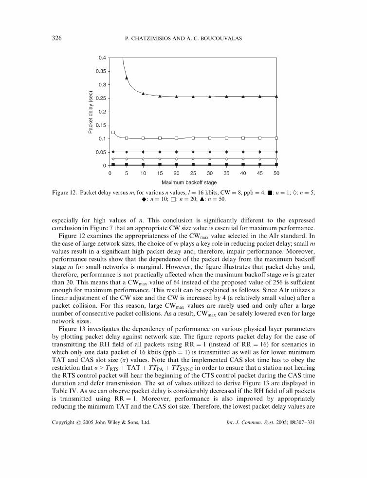
Figure 12 examines the appropriateness of the CWmax value selected in the AIr standard. Inthe case of large network sizes, the choice of m plays a key role in reducing packet delay; small mvalues result in a significant high packet delay and, therefore, impair performance. Moreover,performance results show that the dependence of the packet delay from the maximum backoffstage m for small networks is marginal. However, the figure illustrates that packet delay and,therefore, performance is not practically affected when the maximum backoff stage m is greaterthan 20. This means that a CWmax value of 64 instead of the proposed value of 256 is sufficientenough for maximum performance. This result can be explained as follows. Since AIr utilizes alinear adjustment of the CW size and the CW is increased by 4 (a relatively small value) after apacket collision. For this reason, large CWmax values are rarely used and only after a largenumber of consecutive packet collisions. As a result, CWmax can be safely lowered even for largenetwork sizes.
Figure 13 investigates the dependency of performance on various physical layer parametersby plotting packet delay against network size. The figure reports packet delay for the case oftransmitting the RH field of all packets using RR ¼ 1 (instead of RR ¼ 16) for scenarios inwhich only one data packet of 16 kbits (ppb ¼ 1) is transmitted as well as for lower minimumTAT and CAS slot size (s) values. Note that the implemented CAS slot time has to obey therestriction that s > TRTS þ TATþ TTPA þ TTSYNC in order to ensure that a station not hearingthe RTS control packet will hear the beginning of the CTS control packet during the CAS timeduration and defer transmission. The set of values utilized to derive Figure 13 are displayed inTable IV. As we can observe packet delay is considerably decreased if the RH field of all packetsis transmitted using RR ¼ 1: Moreover, performance is also improved by appropriatelyreducing the minimum TAT and the CAS slot size. Therefore, the lowest packet delay values are
0
0.05
0.1
0.15
0.2
0.25
0.3
0.35
0.4
0 5 10 15 20 25 30 35 40 45 50
Maximum backoff stage
Pac
ket d
elay
(se
c)
Figure 12. Packet delay versus m; for various n values, l ¼ 16 kbits; CW ¼ 8; ppb ¼ 4:&: n ¼ 1; }: n ¼ 5;^: n ¼ 10; &: n ¼ 20; m: n ¼ 50:
Copyright # 2005 John Wiley & Sons, Ltd. Int. J. Commun. Syst. 2005; 18:307–331
P. CHATZIMISIOS AND A. C. BOUCOUVALAS326

achieved for RR ¼ 1 and for the much smaller than the proposed TAT and s values(TAT ¼ 10; s ¼ 50).
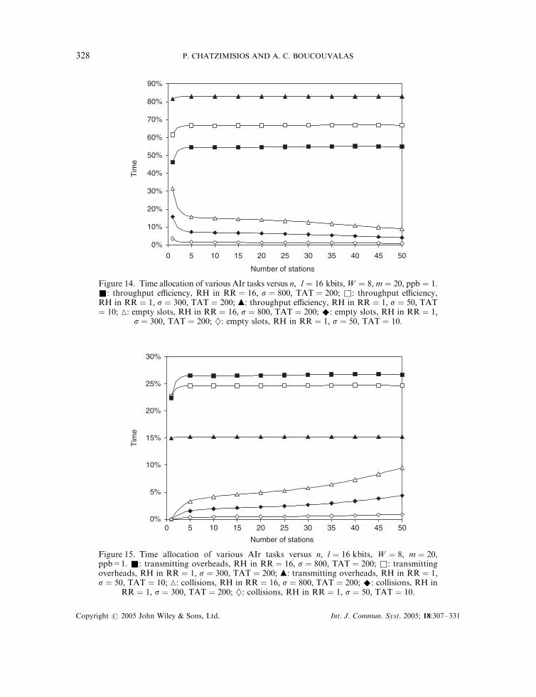
In Figures 14 and 15 we clearly demonstrate why performance is considerably improved whenthe RH field of all packets is transmitted using RR ¼ 1 and when smaller values TAT and svalues are implemented. These figures plot throughput efficiency and the time portion utilizedon empty slots (Figure 14) and the time portion utilized in packet collisions and in transmittingoverheads during a successful transmission (Figure 15). Figure 14 shows that performance issignificantly enhanced when RH is transmitted in RR ¼ 1 and for lower TAT and s values sincemore time is utilized for useful transmission and less time is consumed in empty slots. Figure 15also confirms the previous conclusion since much less time is utilized in transmitting overheadsor in packet collisions.
In Figure 16, packet delay is plotted against packet size in bits in order to study the effect ofthe packet payload size on performance. As it is expected, packet delay increases when packet
0
0.05
0.1
0.15
0.2
0.25
0.3
0.35
0.4
0 5 10 15 20 25 30 35 40 45 50
Number of stations
Pac
ket d
elay
(se
c)
Figure 13. Packet delay versus n; for various physical layer parameters, l ¼ 16 kbits; CW ¼ 8;m ¼ 20: &: RR ¼ 1; s ¼ 50; TAT ¼ 10; ppb ¼ 1; }: RR ¼ 1; s ¼ 100; TAT ¼ 50; ppb ¼ 1;^: RR ¼ 1; s ¼ 300; TAT ¼ 200; ppb ¼ 1; &: RR ¼ 16; s ¼ 700; TAT ¼ 100; ppb ¼ 1; m:
RR ¼ 16; s ¼ 800; TAT ¼ 200; ppb ¼ 1:
Table IV. AIr physical and link layer parameters for improved performance.
RR
Parameter 16 16 1 1 1TAT 200 100 200 50 10TRTS þ TATþ TPA þ TSYNC 548 448 428 278 238CAS duration ðsÞ 800 700 300 100 50Fs 252 252 132 132 132D 1740 1340 1260 660 500
Copyright # 2005 John Wiley & Sons, Ltd. Int. J. Commun. Syst. 2005; 18:307–331
PACKET DELAY ANALYSIS 327
0%
10%
20%
30%
40%
50%
60%
70%
80%
90%
0 5 10 15 20 25 30 35 40 45 50
Number of stations
Tim
e
Figure 14. Time allocation of various AIr tasks versus n; l ¼ 16 kbits;W ¼ 8; m ¼ 20; ppb ¼ 1:&: throughput efficiency, RH in RR ¼ 16; s ¼ 800; TAT ¼ 200; &: throughput efficiency,RH in RR ¼ 1; s ¼ 300; TAT ¼ 200; m: throughput efficiency, RH in RR ¼ 1; s ¼ 50; TAT¼ 10; 4: empty slots, RH in RR ¼ 16; s ¼ 800; TAT ¼ 200; ^: empty slots, RH in RR ¼ 1;
s ¼ 300; TAT ¼ 200; }: empty slots, RH in RR ¼ 1; s ¼ 50; TAT ¼ 10:
0%
5%
10%
15%
20%
25%
30%
0 5 10 15 20 25 30 35 40 45 50
Number of stations
Tim
e
Figure 15. Time allocation of various AIr tasks versus n; l ¼ 16 kbits; W ¼ 8; m ¼ 20;ppb=1. &: transmitting overheads, RH in RR ¼ 16; s ¼ 800; TAT ¼ 200; &: transmittingoverheads, RH in RR ¼ 1; s ¼ 300; TAT ¼ 200; m: transmitting overheads, RH in RR ¼ 1;s ¼ 50; TAT ¼ 10; 4: collisions, RH in RR ¼ 16; s ¼ 800; TAT ¼ 200; ^: collisions, RH in
RR ¼ 1; s ¼ 300; TAT ¼ 200; }: collisions, RH in RR ¼ 1; s ¼ 50; TAT ¼ 10:
Copyright # 2005 John Wiley & Sons, Ltd. Int. J. Commun. Syst. 2005; 18:307–331
P. CHATZIMISIOS AND A. C. BOUCOUVALAS328

size increases, especially in large network scenarios. However, it is understandable that throughputefficiency is improved when large-size packets are transmitted since in this way the negative effect onperformance of the packet overhead is minimized. For this reason, we are opposite a trade-offbetween throughput efficiency and packet delay performance as the network size increases.
6. CONCLUSIONS
In this paper, we presented a new and simpler derivation of the performance model in Reference[23]. This new derivation is simpler than the original one and accurate since is validated bycomparison with OPNET simulation results. Furthermore, a novel and intuitive analysis isderived that leads to simple equations for the average packet delay of the AIr protocol. Utilizingthe proposed analysis, we present an extensive AIr packet delay evaluation by taking intoaccount all the factors and parameters that affect protocol performance.
We observe that when no CW size adjustment is imposed ðm ¼ 0Þ after a successfulreservation or collision, packet delay performance is significantly affected particularly for smallnetwork sizes; a suitable CW size value should be chosen for maximum performance. Moreover,results show that performance does not considerably depend on the maximum backoff stage form values greater than 20. Another important parameter that affects packet delay is the payloadsize of the transmitted data packets. Performance results point out that there is a trade-offbetween throughput efficiency and packet delay performance, especially when the network sizeincreases. Finally, for indoor environments in which small amounts of data (ppb ¼ 1) aretransmitted in every successful reservation attempt, both the RR used in transmitting the RHfield of all packets as well as the minimum TAT can be safely lowered in order to reduce packetdelay and, thus, enhance the performance.
0
0.05
0.1
0.15
0.2
0.25
0.3
2048 4096 6144 8192 10240 12288 14336 16384
Packet size(bits)
Pac
ket d
elay
(se
c)
Figure 16. Packet delay versus l; for various n values, W ¼ 8; m ¼ 20; ppb=4. &: n ¼ 1; }: n ¼ 5;^: n ¼ 10; &: n ¼ 20; m: n ¼ 50:
Copyright # 2005 John Wiley & Sons, Ltd. Int. J. Commun. Syst. 2005; 18:307–331
PACKET DELAY ANALYSIS 329

REFERENCES
1. Williams S. IrDA: past, present and future. IEEE Personal Communications 2000; 7(1):11–19.2. Nee R, Awater G. New high-rate wireless LAN standards. IEEE Communications Magazine 1999; 37(12):82–88.3. IrDA: Serial Infrared Physical Layer Specification}Version 1.1. Infrared Data Association, 1995.4. IrDA: Serial Infrared Physical Layer Specification for 16Mb/s Addition (VFIR)}Errata to Version 1.3. Infrared Data
Association, 1999.5. IrDA: Serial Infrared Link Access Protocol (IrLAP)}Version 1.1. Infrared Data Association, 1996.6. IrDA: Advanced Infrared (AIr) MAC Draft Protocol Specification}Version 1.0. Infrared Data Association, 1999.7. IrDA: Advanced Infrared (AIr) Link Manager Draft Specification}Version 0.3. Infrared Data Association, 1999.8. IrDA: Advanced Infrared Logical Link Control (AIrLC) Specification}Version 1.0 (Infrared Data Association,
1999).9. IrDA: Advanced Infrared Physical Layer Specification (AIr-PHY)}Version 1.0. Infrared Data Association, 1998.10. Ozugur T, Copeland JA, Naghshineh M, Kermani P. Next generation indoor infrared-LANs: issues and approaches.
IEEE Personal Communications Magazine 1999; 6(6):6–19.11. Gfeller F, Hirt W. Advanced infrared (AIr): physical layer for reliable transmission and medium access. Proceedings
of International Zurich Seminar on Broadband Communications, 2000; 77–84.12. Ozugur T, Naghshineh M, Kermani P, Olsen CM, Rezvani B, Copeland JA. Performance evaluation of L-PPM
links using repetition rate coding. Proceedings of IEEE PIMRC’98, Boston, U.S.A., September 1998; 698–702.13. Kleinrock L, Tobagi F. Packet switching in radio channels, part II}the hidden terminal problem in carrier sense
multiple access and the busy tone solution. IEEE Transactions in Communications 1975; 23(12):1417–1433.14. Wireless LAN Medium Access Control (MAC) and Physical Layer (PHY) Specification. IEEE 802.11 WG: New
York, 1999.15. Crow BP, Widjaja I, Kim JG, Sakai PT. IEEE 802.11 wireless local area networks. IEEE Communication Magazine
1997; 35(9):116–126.16. Bianchi G. Performance analysis of the IEEE 802.11 distributed coordination function. IEEE Journal on Selected
Areas in Communications 2000; 18(3):535–547.17. Chatzimisios P, Vitsas V, Boucouvalas AC. Throughput and delay analysis of IEEE 802.11 protocol. Proceedings of
IEEE International Workshop on Networked Appliances (IWNA), Liverpool, U.K., October 2002; 168–174.18. Chatzimisios P, Boucouvalas AC, Vitsas V. IEEE 802.11 packet delay}a finite retry limit analysis. Proceedings of
IEEE Global Telecommunications Conference (Globecom), San Francisco, U.S.A., December 2003; 950–954.19. Bianchi G, Tinnirello I. Remarks on IEEE 802.11 DCF performance analysis. IEEE Communication Letters 2004,
to appear.20. Vitsas V, Boucouvalas AC. Performance evaluation of IrDA advanced infrared AIr–MAC protocols. Proceedings of
the Fifth Multi-Conference on Systemics, Cybernetics, and Informatics, vol. IV, Orlando, U.S.A., July 2001; 347–352.21. Vitsas V, Boucouvalas AC. Performance analysis of the AIr-MAC optical wireless protocol. Proceedings of the
International Conference on System Engineering, Communications and Information Technologies (ICSECIT 2001),Punta Arenas, Chile, April 2001.
22. Ozugur T, Naghshineh M, Kermani P, Copeland JA. Fair media access for wireless LANs. Proceedings of IEEEGLOBECOM’99, Rio de Janeiro, Brazil, 1999; 570–579.
23. Vitsas V, Boucouvalas AC. Performance analysis of the advanced infrared (AIr) CSMA/CA MAC protocol forwireless LANs. Wireless Networks 2003; 9(5):495–507.
24. OPNETTM Modeller. MIL3 Inc., 3400 International Drive NW, Washington, DC, 20008, U.S.A.
AUTHORS’ BIOGRAPHIES
Periklis Chatzimisios received his BSc degree in Informatics from TechnologicalEducational Institution of Thessaloniki, Greece, in 2000. He is currently pursuing aPhD in wireless communication protocols with the School of Design, Engineering &Computing (DEC) at Bournemouth University, U.K. His research focuses onperformance modelling and analysis as well as discrete-event simulation of wirelesscommunication protocols and communication networks. He has published over 20papers in the areas of wireless communications (especially IEEE 802.11 and IrDA)and network management. Mr Chatzimisios is a student member of IEEE, IEE and aprofessional member of ACM.
Copyright # 2005 John Wiley & Sons, Ltd. Int. J. Commun. Syst. 2005; 18:307–331
P. CHATZIMISIOS AND A. C. BOUCOUVALAS330

Anthony C. Boucouvalas received the BSc degree in Electrical and ElectronicEngineering from Newcastle upon Tyne University, U.K., in 1978. He received hisMSc and DIC degrees in Communications Engineering from Imperial College,University of London, U.K., in 1979, and the PhD degree in fibre optics fromImperial College, in 1982.Subsequently he joined GEC Hirst Research Centre, andbecame Group Leader and Divisional Chief Scientist working on fibre opticcomponents, measurements and sensors, until 1987, when he joined Hewlett PackardLaboratories as Project Manager. At HP he worked in the areas of opticalcommunication systems, optical networks, and instrumentation, until 1994, when hejoined Bournemouth University. In 1996 he became a Professor in MultimediaCommunications, and in 1999 became Director of the Microelectronics andMultimedia research Centre.
His current research interests lie in optical wireless communications, optical fibre communications,multimedia communications, and human–computer interfaces. He has published over 200 papers in theareas of fibre optics, optical fibre components, optical wireless communications and InternetCommunications, and HCI.Prof. Boucouvalas is a Fellow of the Inst. Elect. Eng. (FIEE), a Fellow of the Royal Society for the
encouragement of Arts, Manufacturers and Commerce, (FRSA), and a Member of the New YorkAcademy of Sciences, and ACM. He is an Editor of the IEEE Wireless Communications Magazine, IEEETransactions on Wireless Networks, EURASIP Journal on Wireless Communications and Networks,Wireless Communications and Mobile Computing Journal. He is the Vice Chairman of the IEEE UK&RICommunications Chapter and he is member of the Architectures Council of IrDA. He is in the OrganizingCommittee of the International Symposium on Communication Systems Networks and Digital SignalProcessing, (CSNDSP), Vice Chair of IEEE GLOBECOM 2003 for Optical Networking and Systems anda member of Technical Committees in numerous conferences.
Copyright # 2005 John Wiley & Sons, Ltd. Int. J. Commun. Syst. 2005; 18:307–331
PACKET DELAY ANALYSIS 331