packaged air handling products mua-ds-4 make-up … air handling... · blower and coil section —...
TRANSCRIPT

MUA-DS-4February 1998Second Printing
PackagedAir HandlingProducts
For Cooling, Ventilating andMake-Up Air Applications
MU
A-D
S-4

2©American Standard Inc. 1998
FeaturesandBenefits
The Trane packaged air handlingproduct line is suitable for cooling,ventilating and make-up airapplications. Unit sizes range from1500 to 14,000 cfm (0.7-6.6 cu. m/s)with 1/2 to 15 hp motor capabilities.
Units are ETL and CSA certified to UL-1995 standard for heating, cooling andventilating equipment. Units areavailable in one of eight standardarrangements. Air handling units aresuitable for commercial, institutionaland industrial applications whereexternal system pressure losses are ashigh as three inches WC.
Arrangements are divided into twoclassifications — standard and highcfm blower types.
The standard blower unit consists of ablower cabinet that houses thedampers, filters and blower in onecabinet. An optional evaporativecooling unit with standard 8 or optional12-inch media may also be included.
The high cfm blower unit uses aseparate damper/filter cabinet with a V-bank filter arrangement and a blowercabinet. An optional coil cabinet isoffered on units with a cfm range of upto 6,300. Both standard and high cfmblower arrangements may also includea downturn supply air plenum, outsideair and/or return air, intake hood and aroof curb.
All units are completely packaged, railmounted and wired to help assure asmooth installation and easy start-up.
Air control options offer a similar rangeof control features from manualdampers to modulating dampers thatmay include mixed air, dry bulb,pressure sensing, enthalpy control,DDC interface or ASHRAE Cycle controlarrangements.
Features and Benefits
• ETL and CSA UL-1995 Certified.• Cfm ranges from 1,500 to 14,000.• Motor sizes up to 15 hp.• ODP motors with high efficiency and
totally enclosed options.• Draw-thru cooling coil cabinet with
stainless steel drain pan.• Evaporative cooling with standard 8 or
optional 12-inch media (203 or 305mm).
• Insulated roof curb.• Standard 18-gauge cabinets.• Standard one-inch washable filters.• Standard blower door safety interlock
switch.• Standard 24-volt circuit breaker.• Standard printed circuit main
connection board.• Wiring harnesses with stamped wire
numbers.• Over 40 standard air control packages.

3
Features and Benefits 2
Unit Configurations 4
Model Number Description 5
General Data 6
Performance Adjustment Factors 7
Performance Data 8
Electrical Data 14
Controls 15
Dimensional Data 17
Weights 34
Options 35
Features Summary 35
Mechanical Specifications 36
Contents

4
Unit Type Standard FeaturesArrangement B — — Electrical cabinet isolated from the airstream.Air Handler with — Blower door interlock switch with service override.Standard Blower — Insulated Fan Section
— 1” Permanent Filters
Arrangement C — Same as Arrangement B withAir Handler with Standard — Insulated Supply PlenumBlower and DownflowSupply Plenum
Arrangement D — Same as Arrangement B withAir Handler with Standard — Evaporative CoolerBlower and — Sealed pump motor with float valveEvaporative Cooler — Heavy duty stainless steel water tank
— High Efficiency 8 media— Self cleaning design
Arrangement E — Same as Arrangement D withAir Handler with Standard — Insulated Supply PlenumBlower, Evaporative Coolerand DownflowSupply Plenum
Arrangement G — — Blower door interlock switch with service overrideAir Handler with — 1” Permanent FiltersHigh Cfm Blower — Electrical cabinet isolated from the airstream
— Quick opening access door— V bank filter and damper cabinet— Fully insulated filter/damper and blower cabinet
Arrangement J — Same as Arrangement G withAir Handler with High Cfm — Insulated Supply PlenumBlower and DownflowSupply Plenum
Arrangement K — Same as Arrangement G withAir Handler with High Cfm — Coil SectionBlower and Coil Section — Mounting for 4-6 row coils
— Stainless steel drain pan with 3/4” tapped outlets
Arrangement L — Same as Arrangement K withAir Handler with High Cfm — Insulated Supply PlenumBlower, Coil Section andDownflow Supply Plenum
Note: Motors/Air Inlet Configuration/Air Control and Damper Arrangement must be selected for each unit.Legend is as follows:B/F/D — Standard blower/Filter/DamperSP — Supply PlenumEV — Evaporative CoolerF/D — Filter/DamperB — High cfm BlowerCC — Coil Cabinet
Air Inlet Configuration (Digit 18 of the Model Number)
UnitConfigurations
1 2 3 4 5 See Note Below
Note: Horizontal outside air over return air. Specify air inlet configuration 4 or 5and then select miscellaneous option “D” for horizontal return.

5
A H 0 A 20 0 A 0 D0 0 0 C F 1 0 5 H 0 P
1 2 3 4 5,6 7 8 9 10,11 12 13 14 15 16 17 18 19 20 21
ModelNumberDescription
Digit 1,2 — Unit TypeAH = Air Handling Unit
Digit 3 — Furnace Type0 = None
Digit 4 — Development SequenceA = First Generation
Digit 5,6 — Unit Size20 = 1500 - 8000 Cfm40 = 4000 - 14000 Cfm
Digit 7 — Venting Type0 = None
Digit 8 — Main Power SupplyA = 115/60/1B = 208/60/1C = 230/60/1D = 208/60/3E = 230/60/3F = 460/60/3G = 575/60/3S = Special Main Power Supply
Digit 9 — Gas Control Option0 = No gas control option
Digit 10, 11 — Design SequenceDO = Design Sequence
Digit 12 — Fuel Type0 = No selection
Digit 13 — Heat Exchanger Material0 = No selection
Digit 14 — Air Handler ArrangementsB = Blower (Standard)C = Blower (Standard) PlenumD = Blower (Standard) Evaporative CoolerE = Blower (Standard) Evaporative Cooler/
PlenumG = Blower (High CFM)J = Blower (High CFM)/PlenumK = Blower (High CFM)/Coil CabinetL = Blower (High CFM)/Coil Cabinet/
PlenumS = Special Air Handler Arrangement
Digit 15 — Motor SelectionA = 1/2 HP w/contactorB = 3/4 HP w/contactorC = 1 HP w/contactorD = 1 1/2 HP w/contactorE = 2 HP w/contactorF = 3 HP w/contactorG = 5 HP w/contactorH = 1/2 HP w/magnetic starterJ = 3/4 HP w/magnetic starterK = 1 HP w/magnetic starterL = 1 1/2 HP w/magnetic starterN = 2 HP w/magnetic starterP = 3 HP w/magnetic starterQ = 5 HP w/magnetic starterR = 7 1/2 HP w/magnetic starterT = 10 HP w/magnetic starterU = 15 HP w/magnetic starterS = Special Motor
Digit 16 — Motor Speed and Starter0 = No Selection1 = Single Speed ODP 1800 RPM2 = Single Speed TEFC 1800 RPM3 = Single Speed High Efficiency ODP
1800 RPM4 = Single Speed High Efficiency TEFC
1800 RPM5 = 2S1W ODP 1800/900 RPM6 = 2S2W ODP 1800/1200 RPMS= Special Motor Speed and Starter
Digit 17 — Coil Options0 = No cooling coil selectionA = DX coil, 4 Row, Single CircuitB = DX coil, 4 Row, Dual CircuitC = DX coil, 6 Row, Single CircuitD = DX coil, 6 Row, Dual CircuitE = Chilled Water Coil, 4 Row, Single
CircuitG = Chilled Water Coil, 6 Row, Dual CircuitS = Special coil
Digit 18 — Air Inlet Configuration1 = Outside Air (OA) Horizontal Inlet2 = Outside Air W/Air Hood, Horizontal Inlet3 = Bottom Return Air (RA)4 = Outside and Return Air (OA/RA)5 = Outside and Return Air W/Air HoodS= Special Air inlet configuration
Digit 19 — Air Control and DamperArrangements0 = No SelectionA = Outside Air 2 pos. Motor/ SRB = Return Air 2 pos. Motor/ SRC = OA/RA 2 pos SRE = OA/RA Mod Mtr W/Mixed Air Control/
Min Pot/SRH = OA/RA Mod Mtr W/Mixed Air Control/
SRK = OA/RA Mod Mtr W/Min Pot/SRM = OA/RA Mod Mtr w/Dry Bulb/Mixed Air
Control/Min Pot/SRN = OA/RA Mod Mtr w/Enthalpy Controlled
Economizer/SRP = OA/RA Mod Mtr W/ Space Pressure
ControllerR = OA/RA Mod Mtr W/ S-350 P
Proportional Mixed Air Control/SRU = OA/RA MTR. W/External 0-10 VDC and
4-20 mA Analog Input/SR(External Input)
W= ASHRAE Cycle I (OA/RA 2 pos.w/warm-up stat/SR
X = ASHRAE Cycle II (OA/RA ModW/Warm-up Stat/Mixed Air/min pot/SR
Y = ASHRAE Cycle III (OA/RA Mod.W/Warm-up Stat/Mixed Air/SR
Z = Manual DampersS = Special air control and damper
arrangement
Digit 20 — California Shipment0 = Non-California Shipment1 = California Shipment
Digit 21 — Miscellaneous OptionsB = 12” Evaporative Media (Celdek)C = Moisture EliminatorsD = Horizontal ReturnE = Continuous Fan RelayF = FreezestatH = Return Air FirestatJ = Supply Air FirestatK = Manual Blower SwitchN = Double Wall ConstructionP = Low Leak DampersQ = Clogged Filter SwitchW= Interlock Relay — 24/115V Coil
SPDT10AX = Interlock Relay — 24/115/230V Coil
DPDT 10AZ = 8” Evaporative Media (Glasdek)1 = 12” Evaporative Media (Glasdek)2 = Hinged Service Access Doors

6
GeneralData
Packaged Air Handler Arrangement Reference
Filter Data Unit SizeArrangement 20 40
B-E (4) 20 x 20 (6) 20 x 20G-L (8) 20 x 20 (12) 20 x 20
Intake Hood
Blower/Main Electrical(High CFM) 0-15 HP
Damper/Filters(High CFM)
Coil Cabinet(High CFM)
Dampers/Filters/Blower/Main Electrical(Standard) 0-5 HP
Evaporative Cooler(Standard)
Supply Plenum
Standard Blower Standard Blower W/EC-Mate High CFM Blower High CFM Blower W/CoolingArrangements B, C Arrangements D, E Arrangements G, J Arrangements K, L
Capacity 20, 40 Capacity 20, 40 Capacity 20, 40 Capacity 20, 4020 - 1,500-6,000 CFM, 1/2-5 HP 20 - 1,500-6,000 CFM, 1/2-5 HP 20 - 3,000-8,000 CFM, 3/4-10 HP 20 - 3,000-4,300 CFM, 3/4-5 HP40 - 4,000-8,000 CFM, 1/2-5 HP 40 - 4,000-8,000 CFM, 1/2-5 HP 40 - 5,000-14,000 CFM, 3/4-15 HP 40 - 5,000-6,300 CFM, 3/4-7 1/2 HP
ESP .1-3” in WC ESP .1-3” in WC ESP .1-3” in WC ESP .1-3” in WC

7
Metric Conversion TableUnless otherwise specified, the following conversions may be used for calculating SI unitmeasurements:1 cubic foot= 0.028 m3 1 inch water column = 0.029 kPa1 foot = 0.0305 m 1 gallon = 3.785 L1 inch = 25.4 mm 1,000 Btu/Cu. Ft. = 37.5 MJ/m3
1 psig = 6.894 kPa 1 liter/second = CFM x 0.4721 pound = 0.453 kg 1 meter/second = FPM ¸ 196.81,000 Btu per hour = 0.293 kW
PerformanceAdjustmentFactors
Table PAF-1 — Correction Factors for AltitudeAltitude (Feet)
0’ 500’ 1000’ 1500’ 2000’ 2500’ 3000’ 3500’ 4000’ 4500’ 5000’ 5500’ 6000’Temp. Barometric Pressure (In. Hg)
F 39.92 29.38 28.86 28.33 27.82 27.31 26.82 26.32 25.84 25.36 24.9 24.43 29.98 -40 0.79 0.81 0.82 0.84 0.85 0.87 0.88 0.90 0.92 0.93 0.95 0.97 0.99
0 0.87 0.88 0.90 0.92 0.93 0.95 0.97 0.99 1.00 1.02 1.04 1.06 1.08 40 0.94 0.96 0.98 1.00 1.01 1.03 1.05 1.07 1.09 1.11 1.13 1.16 1.18 70 1.00 1.02 1.04 1.06 1.08 1.10 1.12 1.14 1.16 1.18 1.20 1.22 1.25 80 1.02 1.04 1.06 1.08 1.10 1.12 1.14 1.16 1.18 1.20 1.22 1.25 1.27100 1.06 1.08 1.10 1.12 1.14 1.16 1.18 1.20 1.22 1.25 1.27 1.29 1.32120 1.90 1.11 1.13 1.16 1.18 1.20 1.22 1.24 1.27 1.29 1.31 1.34 1.37
1. Actual ESP = Duct ESP x Factor ÷ Accs. SP2. Actual BHP = Cat. BHP ÷ Factor3. Correct BTUH Input = Catalog BTUH Input ÷ Factor4. Corrected BTUH Output = Corrected BTUH Input x Efficiency

8
Table PD-1 — Air Handling Performance Data — Arrangements B-ETotal External Static Pressure (Inches of Water)
0.2 0.4 0.6 0.8 1 1.2 1.4 1.6 1.8 2 2.2 2.4 2.6 2.8 3Capacity CFM RPM BHP RPM BHP RPM BHP RPM BHP RPM BHP RPM BHP RPM BHP RPM BHP RPM BHP RPM BHP RPM BHP RPM BHP RPM BHP RPM BHP RPM BHP
1,500 395 0.12 530 0.19 645 0.27 750 0.35 845 0.44 930 0.54 1010 0.65 1085 0.762,000 435 0.22 550 0.3 655 0.4 750 0.49 835 0.59 915 0.7 995 0.81 1065 0.93 1135 1.063,000 555 0.61 630 0.71 710 0.83 790 0.96 865 1.09 935 1.23 1000 1.37 1065 1.51 1125 1.66 1180 1.81 1240 1.96 1295 2.12 1350 2.28 1405 2.45 1455 2.62
20 4,000 700 1.33 750 1.47 805 1.61 865 1.75 930 1.9 990 2.07 1045 2.25 1105 2.43 1160 2.61 1210 2.8 1260 2.98 1310 3.17 1360 3.35 1405 3.54 1455 3.745,000 855 2.51 890 2.68 930 2.85 975 3.02 1020 3.19 1070 3.37 1120 3.55 1170 3.75 1220 3.96 1265 4.18 1310 4.4 1360 4.63 1400 4.865,500 935 3.3 965 3.49 1000 3.67 1040 3.86 1080 4.05 1120 4.24 1165 4.43 1210 4.63 1255 4.846,000 1015 4.25 1040 4.45 1075 4.65 1105 4.854,000 450 0.46 565 0.64 670 0.82 760 1.01 845 1.22 930 1.43 1005 1.66 1075 1.9 1140 2.15 1205 2.425,000 510 0.79 605 0.99 700 1.21 785 1.44 860 1.67 935 1.91 1005 2.16 1070 2.42 1135 2.69 1200 2.97
40 6,000 575 1.28 655 1.49 740 1.73 815 2. 885 2.28 955 2.56 1020 2.84 1085 3.12 1140 3.41 1200 3.71 1255 4.02 1315 4.34 1365 4.67 1420 5.7,000 650 1.95 715 2.19 785 2.44 855 2.73 920 3.04 985 3.36 1045 3.68 1105 4. 1160 4.33 1215 4.66 1270 4.998,000 725 2.83 780 3.1 840 3.38 905 3.67 965 3.99 1025 4.34 1080 4.71
Note: Refer to Table for Accessory Pressure Losses (Rooftop Arrangement B-E)
Table PD-2 — Air Handling Accessory Pressure Loss Data — Arrangements B-EPressure Loss (Inches of Water)
Rainhood Filters Supply Evaporative Return or OutsideWith Throwaway Washable Pleated Air Media Air
Capacity CFM Screen Mstr. Elim. 2” 1” 2” 1” 2” Plenum 8” 12” Damper1,600 .02 .02 .05 <.01 .01 .06 .03 .02 .02 .03 .031,800 .02 .03 .06 <.01 .01 .07 .04 .03 .02 .03 .032,000 .02 .03 .07 .01 .02 .08 .04 .03 .03 .04 .042,200 .03 .04 .08 .01 .02 .09 .05 .04 .03 .05 .05
20 2,400 .03 .05 .09 .02 .02 .11 .06 .05 .04 .06 .052,500 .04 .05 .09 .02 .03 .12 .07 .05 .04 .07 .063,000 .05 .07 .12 .03 .04 .16 .09 .07 .06 .10 .084,000 .09 .13 .17 .05 .07 .26 .16 .13 .11 .17 .155,000 .15 .20 .07 .11 .38 .23 .21 .18 .27 .235,500 .18 .25 .09 .13 .44 .28 .25 .22 .32 .283,200 .03 .04 .07 .01 .02 .09 .05 .02 .04 .06 .043,600 .04 .05 .09 .02 .02 .11 .06 .03 .05 .07 .054,000 .04 .06 .10 .02 .03 .13 .07 .04 .06 .09 .074,400 .05 .07 .11 .03 .04 .15 .09 .05 .07 .11 .08
40 4,800 .06 .09 .13 .03 .04 .18 .10 .05 .09 .13 .105,000 .07 .10 .13 .03 .05 .19 .11 .06 .09 .14 .106,000 .10 .14 .17 .05 .07 .26 .16 .08 .14 .20 .157,000 .13 .19 .07 .09 .33 .21 .11 .18 .27 .208,000 .17 .24 .09 .12 .42 .26 .15 .24 .36 .268,500 .20 .28 .10 .14 .17 .27 .41 .30
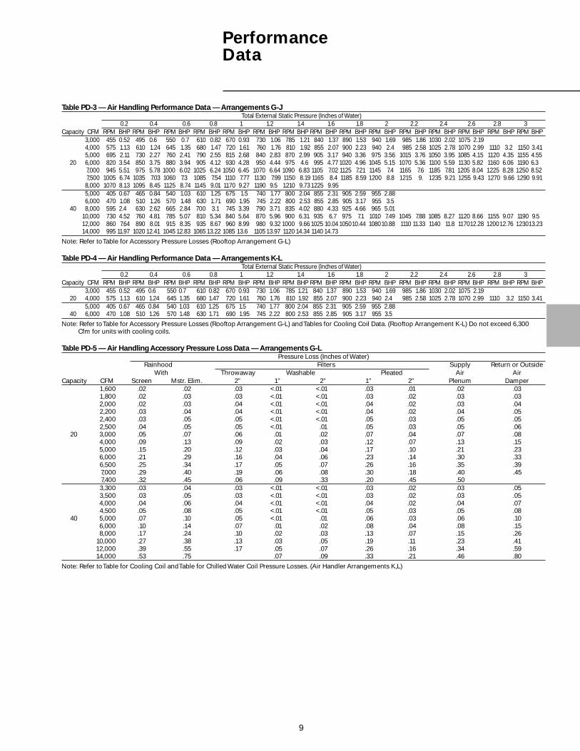
PerformanceData
9
Table PD-3 — Air Handling Performance Data — Arrangements G-JTotal External Static Pressure (Inches of Water)
0.2 0.4 0.6 0.8 1 1.2 1.4 1.6 1.8 2 2.2 2.4 2.6 2.8 3Capacity CFM RPM BHP RPM BHP RPM BHP RPM BHP RPM BHP RPM BHP RPM BHP RPM BHP RPM BHP RPM BHP RPM BHP RPM BHP RPM BHP RPM BHP RPM BHP
3,000 455 0.52 495 0.6 550 0.7 610 0.82 670 0.93 730 1.06 785 1.21 840 1.37 890 1.53 940 1.69 985 1.86 1030 2.02 1075 2.194,000 575 1.13 610 1.24 645 1.35 680 1.47 720 1.61 760 1.76 810 1.92 855 2.07 900 2.23 940 2.4 985 2.58 1025 2.78 1070 2.99 1110 3.2 1150 3.415,000 695 2.11 730 2.27 760 2.41 790 2.55 815 2.68 840 2.83 870 2.99 905 3.17 940 3.36 975 3.56 1015 3.76 1050 3.95 1085 4.15 1120 4.35 1155 4.55
20 6,000 820 3.54 850 3.75 880 3.94 905 4.12 930 4.28 950 4.44 975 4.6 995 4.77 1020 4.96 1045 5.15 1070 5.36 1100 5.59 1130 5.82 1160 6.06 1190 6.37,000 945 5.51 975 5.78 1000 6.02 1025 6.24 1050 6.45 1070 6.64 1090 6.83 1105 7.02 1125 7.21 1145 7.4 1165 7.6 1185 7.81 1205 8.04 1225 8.28 1250 8.527,500 1005 6.74 1035 7.03 1060 7.3 1085 7.54 1110 7.77 1130 7.99 1150 8.19 1165 8.4 1185 8.59 1200 8.8 1215 9. 1235 9.21 1255 9.43 1270 9.66 1290 9.918,000 1070 8.13 1095 8.45 1125 8.74 1145 9.01 1170 9.27 1190 9.5 1210 9.731225 9.955,000 405 0.67 465 0.84 540 1.03 610 1.25 675 1.5 740 1.77 800 2.04 855 2.31 905 2.59 955 2.886,000 470 1.08 510 1.26 570 1.48 630 1.71 690 1.95 745 2.22 800 2.53 855 2.85 905 3.17 955 3.5
40 8,000 595 2.4 630 2.62 665 2.84 700 3.1 745 3.39 790 3.71 835 4.02 880 4.33 925 4.66 965 5.0110,000 730 4.52 760 4.81 785 5.07 810 5.34 840 5.64 870 5.96 900 6.31 935 6.7 975 7.1 1010 7.49 1045 7.88 1085 8.27 1120 8.66 1155 9.07 1190 9.512,000 860 7.64 890 8.01 915 8.35 935 8.67 960 8.99 980 9.32 1000 9.66 1025 10.04 105010.44 108010.88 1110 11.33 1140 11.8 117012.28 120012.76 123013.2314,000 995 11.97 1020 12.41 1045 12.83 1065 13.22 1085 13.6 1105 13.97 1120 14.34 1140 14.73
Note: Refer to Table for Accessory Pressure Losses (Rooftop Arrangement G-L)
Table PD-4 — Air Handling Performance Data — Arrangements K-LTotal External Static Pressure (Inches of Water)
0.2 0.4 0.6 0.8 1 1.2 1.4 1.6 1.8 2 2.2 2.4 2.6 2.8 3Capacity CFM RPM BHP RPM BHP RPM BHP RPM BHP RPM BHP RPM BHP RPM BHP RPM BHP RPM BHP RPM BHP RPM BHP RPM BHP RPM BHP RPM BHP RPM BHP
3,000 455 0.52 495 0.6 550 0.7 610 0.82 670 0.93 730 1.06 785 1.21 840 1.37 890 1.53 940 1.69 985 1.86 1030 2.02 1075 2.1920 4,000 575 1.13 610 1.24 645 1.35 680 1.47 720 1.61 760 1.76 810 1.92 855 2.07 900 2.23 940 2.4 985 2.58 1025 2.78 1070 2.99 1110 3.2 1150 3.41
5,000 405 0.67 465 0.84 540 1.03 610 1.25 675 1.5 740 1.77 800 2.04 855 2.31 905 2.59 955 2.8840 6,000 470 1.08 510 1.26 570 1.48 630 1.71 690 1.95 745 2.22 800 2.53 855 2.85 905 3.17 955 3.5
Note: Refer to Table for Accessory Pressure Losses (Rooftop Arrangement G-L) and Tables for Cooling Coil Data. (Rooftop Arrangement K-L) Do not exceed 6,300Cfm for units with cooling coils.
Table PD-5 — Air Handling Accessory Pressure Loss Data — Arrangements G-LPressure Loss (Inches of Water)
Rainhood Filters Supply Return or OutsideWith Throwaway Washable Pleated Air Air
Capacity CFM Screen Mstr. Elim. 2” 1” 2” 1” 2” Plenum Damper 1,600 .02 .02 .03 <.01 <.01 .03 .01 .02 .03 1,800 .02 .03 .03 <.01 <.01 .03 .02 .03 .03 2,000 .02 .03 .04 <.01 <.01 .04 .02 .03 .04 2,200 .03 .04 .04 <.01 <.01 .04 .02 .04 .05 2,400 .03 .05 .05 <.01 <.01 .05 .03 .05 .05 2,500 .04 .05 .05 <.01 .01 .05 .03 .05 .06
20 3,000 .05 .07 .06 .01 .02 .07 .04 .07 .08 4,000 .09 .13 .09 .02 .03 .12 .07 .13 .15 5,000 .15 .20 .12 .03 .04 .17 .10 .21 .23 6,000 .21 .29 .16 .04 .06 .23 .14 .30 .33 6,500 .25 .34 .17 .05 .07 .26 .16 .35 .39 7,000 .29 .40 .19 .06 .08 .30 .18 .40 .45 7,400 .32 .45 .06 .09 .33 .20 .45 .50 3,300 .03 .04 .03 <.01 <.01 .03 .02 .03 .05 3,500 .03 .05 .03 <.01 <.01 .03 .02 .03 .05 4,000 .04 .06 .04 <.01 <.01 .04 .02 .04 .07 4,500 .05 .08 .05 <.01 <.01 .05 .03 .05 .08
40 5,000 .07 .10 .05 <.01 .01 .06 .03 .06 .10 6,000 .10 .14 .07 .01 .02 .08 .04 .08 .15 8,000 .17 .24 .10 .02 .03 .13 .07 .15 .2610,000 .27 .38 .13 .03 .05 .19 .11 .23 .4112,000 .39 .55 .17 .05 .07 .26 .16 .34 .5914,000 .53 .75 .07 .09 .33 .21 .46 .80
Note: Refer to Table for Cooling Coil and Table for Chilled Water Coil Pressure Losses. (Air Handler Arrangements K,L)
PerformanceData

10
PerformanceData
Table PD-6 — DX Cooling Coil Performance Data (Ref. R-22) — Rooftop Arrangements K, LCapacity based on 95 F EDB, 74 F EWB, 45 F Sat. Suction, 100 F Liquid
Number of RowsAir Face Fin 4 6
Unit Flow Velocity Spacing Capacity L.A.T. A.P.D. WT. Capacity L.A.T. A.P.D. WT.Capacity (SCFM) (FPM) (FPF) (MBH) (DB/WB) In. W.C. (LBS) (MBH) (DB/WB) In. W.C. (LBS)20 1600 217 *96 91.1 59 / 58 0.11 84 115
*120 99.5 56 / 56 0.12 89 122144 106.4 54 / 54 0.13 95 120.8 51 / 51 0.20 130
2000 271 96 105.3 61 / 59 0.17 84 129.3 55 / 55 0.25 115120 117.2 58 / 57 0.18 89 138.7 53 / 53 0.27 122144 126.6 56 / 55 0.20 95 145.3 52 / 52 0.29 130
3000 407 96 136.1 64 / 61 0.33 84 171.4 58 / 57 0.50 115120 154.4 61 / 59 0.36 89 186.6 56 / 56 0.54 122144 169.8 58 / 58 0.38 95 198.1 54 / 54 0.57 130
4000 542 96 160.0 66 / 63 0.51 84 204.4 61 / 60 0.77 115120 184.1 63 / 61 0.55 89 224.8 58 / 58 0.82 122144 205.2 61 / 59 0.59 95 243.3 56 / 56 0.87 130
4400 596 96 168.6 67 / 64 0.58 84 215.7 62 / 60 0.87 115120 194.5 64 / 62 0.63 89 238.1 59 / 59 0.94 122144 217.7 61 / 60 0.67 95 261.2 57 / 57 1.00 130
40 3300 304 96 173.1 61 / 59 0.21 115 207.5 56 / 55 0.31 158120 191.6 58 / 57 0.22 122 224.7 54 / 54 0.33 170144 205.9 56 / 56 0.24 130 237.6 52 / 52 0.36 182
4000 369 96 194.3 63 / 60 0.29 115 238.6 57 / 57 0.43 158120 216.5 60 / 58 0.31 122 260.6 55 / 55 0.46 170144 234.1 58 / 57 0.33 130 277.7 53 / 53 0.49 182
5000 461 96 219.9 65 / 62 0.40 115 277.9 59 / 58 0.60 158120 246.8 62 / 60 0.43 122 306.9 56 / 56 0.65 170144 271.9 59 / 58 0.46 130 330.3 54 / 54 0.69 182
6000 553 96 241.3 66 / 63 0.53 115 312.4 60 / 59 0.79 158120 273.5 63 / 61 0.56 122 348.2 58 / 57 0.85 170144 307.7 61 / 59 0.60 130 377.9 56 / 55 0.91 182
6300 581 96 247.1 67 / 63 0.56 115 321.9 61 / 60 0.84 158120 281.7 64 / 62 0.60 122 359.7 58 / 57 0.91 170144 317.7 61 / 60 0.64 130 391.3 56 / 56 0.97 182
Conversions:
2119 SCFM = 1 m/s196.8 FPM = 1 m/s3.412 MBH = 1 kW(F-32) 5/9 = C1 In. W.C. = 248.8 Pa1 LB. = 0.453 kg
Notes:
1.) Data certified in accordance with ARI Standard 410.2.) Capacity based on 95 F EDB, 74 F EWB, 45 F Sat. Suction, 100 F Liquid.3.) Weight listed is the total weight of the dry coil.4.) Coils denoted by an asterisk ( * ) require special pricing; consult product marketing for special coil requirements and pricing.

11
PerformanceData
Table PD-7 — DX Cooling Coil Performance Data (Ref. R-22) — Rooftop Arrangements K, LCapacity based on 80 F EDB, 67 F EWB, 45 F Sat. Suction, 100 F Liquid
Number of RowsAir Face Fin 4 6
Unit Flow Velocity Spacing Capacity L.A.T. A.P.D. WT. Capacity L.A.T. A.P.D. WT.Capacity (SCFM) (FPM) (FPF) (MBH) (DB/WB) In. W.C. (LBS) (MBH) (DB/WB) In. W.C. (LBS)
20 1600 217 *96 84 115*120 89 122*144 95 79.8 50 / 50 0.19 130
2000 271 *96 84 115*120 89 122144 82.2 54 / 54 0.20 95 97.7 51 / 51 0.29 130
3000 407 96 88.2 59 / 58 0.33 84 112.0 56 / 55 0.50 115120 97.7 58 / 57 0.36 89 123.1 54 / 54 0.53 122144 107.5 56 / 56 0.38 95 131.8 53 / 53 0.57 130
4000 542 96 101.3 61 / 59 0.51 84 134.3 57 / 56 0.77 115120 116.3 59 / 58 0.54 89 149.4 55 / 55 0.82 122144 130.5 57 / 57 0.58 95 161.7 54 / 54 0.87 130
4400 596 96 105.6 62 / 60 0.58 84 142.1 58 / 57 0.87 115120 123.1 60 / 58 0.62 89 158.7 56 / 55 0.94 122144 138.6 58 / 57 0.66 95 172.3 55 / 54 1.00 130
40 3300 304 *96 113.2 57 / 56 0.21 115 158*120 126.2 55 / 55 0.22 122 170144 136.5 54 / 54 0.24 130 155.2 51 / 51 0.36 182
4000 369 96 127.4 58 / 57 0.29 115 156.7 55 / 54 0.43 158120 143.1 56 / 56 0.31 122 168.7 53 / 53 0.46 170144 155.9 55 / 54 0.33 130 179.8 52 / 52 0.48 182
5000 461 96 144.9 60 / 58 0.40 115 179.0 56 / 56 0.60 158120 164.1 58 / 57 0.43 122 197.6 55 / 54 0.64 170144 180.2 56 / 55 0.46 130 213.9 53 / 53 0.68 182
6000 553 96 159.7 61 / 59 0.53 115 199.4 57 / 56 0.79 158120 182.0 59 / 58 0.57 122 224.5 55 / 55 0.84 170144 201.1 57 / 56 0.61 130 245.1 54 / 54 0.90 182
6300 581 96 163.8 61 / 59 0.56 115 205.6 58 / 57 0.84 158120 186.9 59 / 58 0.61 122 232.1 56 / 55 0.90 170144 206.9 57 / 57 0.65 130 253.9 54 / 54 0.96 182
Conversions:
2119 SCFM = 1 m/s196.8 FPM = 1 m/s3.412 MBH = 1 kW(F-32) 5/9 = C1 In. W.C. = 248.8 Pa1 LB. = 0.453 kg
Table PD-8 — Standard Conditions and Specifications — Refrigerant DX CoilCONDITIONS
Elevation 0 Ft.Entering Air Temperature DB: 80 F 95 FEntering Air Temperature WB: 67 F 74 FSuction Temperature: 45 F 45 FLiquid Temperature: 100 F 100 FFouling Factor: 0 HR x FT2 x F/BTUSPECIFICATIONS
Coil Type: DE optional DHTube Size: 1/2” O.D. x 0.016” TWT CopperRow Sizes: 4,6Fin Type: Delta-FloFin Size: 0.0055” AluminumFin Spacing: Standard — 96, (120), 144 Fins/Ft.
Optional — 72 thru 180 Fins/Ft.Circuiting: Standard — Single
Optional — Dual:a) Intertwinedb) Face-Split
Turbulators: NoDIMENSIONAL DATA LISTING
Unit Size Finned Width Fixed Finned Length20 30.00 34.0040 30.00 50.00
Note:1. Above specification is for standard coil with standard fin spacing.
Specify fin spacing and dual circuiting.2. Special coils — contact Product Marketing.3. Every order requires a coil selection.
Notes:1.) Data certified in accordance with ARI Standard 410.2.) Capacity based on 80 F EDB, 67 F EWB, 45 F Sat. Suction, 100 F Liquid.3.) Weight listed is the total weight of the dry coil.4.) Coils denoted by an asterisk ( * ) require special pricing; consult product marketing for special coil requirements and pricing.

12
PerformanceData
Table PD-9 — Chilled Water Coil Performance Data — Rooftop Arrangements K, LCapacity based on 95 F EDB, 74 F EWB, 45 EWT, 70 GPM
Number of RowsAir Face Fin 4 6
Unit Flow Velocity Spacing Capacity L.A.T. A.P.D. WT. Capacity L.A.T. A.P.D. WT.Capacity (SCFM) (FPM) (FPF) (MBH) (DB/WB) In. W.C. (LBS) (MBH) (DB/WB) In. W.C. (LBS)
20 1800 254 96 109.8 58 / 56 0.12 84 131.2 52 / 52 0.18 115120 119.0 55 / 54 0.14 89 138.6 50 / 50 0.21 122144 126.3 53 / 53 0.16 95 143.9 49 / 49 0.24 130
3000 424 96 148.1 63 / 60 0.27 84 185.5 57 / 56 0.40 115120 163.0 60 / 58 0.31 89 199.9 55 / 54 0.46 122144 174.9 58 / 57 0.35 95 210.8 53 / 53 0.52 130
4300 607 96 175.1 67 / 63 0.47 84 226.1 61 / 59 0.70 115120 195.3 64 / 61 0.52 89 247.5 58 / 57 0.78 122144 210.8 62 / 60 0.60 95 263.2 56 / 56 0.90 130
40 2100 202 96 136.2 56 / 55 0.08 115 159.5 51 / 51 0.12 158120 146.9 54 / 53 0.09 122 167.5 49 / 49 0.14 170144 155.0 52 / 51 0.11 130 172.9 48 / 48 0.16 182
3500 336 96 188.4 61 / 59 0.19 115 230.8 55 / 54 0.28 158120 205.7 58 / 57 0.22 122 246.5 53 / 53 0.33 170144 219.6 56 / 55 0.25 130 258.6 51 / 51 0.37 182
4900 470 96 223.8 64 / 61 0.32 115 281.9 59 / 57 0.47 158120 247.4 62 / 60 0.36 122 305.8 56 / 56 0.54 170144 265.9 60 / 58 0.41 130 323.6 55 / 54 0.61 182
6300 605 96 250.4 67 / 63 0.46 115 321.3 61 / 60 0.68 158120 278.8 64 / 62 0.51 122 351.4 59 / 58 0.77 170144 300.7 62 / 61 0.59 130 373.6 57 / 57 0.89 182
Conversions:
2119 SCFM = 1 m/s196.8 FPM = 1 m/s3.412 MBH = 1 kW(F-32) 5/9 = C1 In. W.C. = 248.8 Pa1 LB. = 0.453 kg
Table PD-10 — Chilled Water Coil Performance Data — Rooftop Arrangements K, LCapacity based on 80 F EDB, 67 F EWB, 45 EWT, 70 GPM
Number of RowsAir Face Fin 4 6
Unit Flow Velocity Spacing Capacity L.A.T. A.P.D. WT. Capacity L.A.T. A.P.D. WT.Capacity (SCFM) (FPM) (FPF) (MBH) (DB/WB) In. W.C. (LBS) (MBH) (DB/WB) In. W.C. (LBS)
20 1800 254 96 77.4 54 / 53 0.12 84 92.3 50 / 50 0.18 115120 83.9 52 / 52 0.14 89 97.5 49 / 49 0.21 122144 89.0 51 / 50 0.16 95 101.2 48 / 48 0.24 130
3000 424 96 104.9 58 / 56 0.27 84 131.0 53 / 53 0.40 115120 115.5 56 / 55 0.31 89 141.2 52 / 51 0.47 122144 123.7 54 / 54 0.35 95 148.6 51 / 50 0.53 130
4300 607 96 124.5 60 / 58 0.47 84 160.1 56 / 55 0.70 115120 138.4 58 / 57 0.53 89 174.9 54 / 54 0.79 122144 149.2 57 / 56 0.60 95 185.9 53 / 53 0.90 130
40 2100 202 96 95.9 53 / 52 0.08 115 112.1 49 / 49 0.12 158120 103.4 51 / 51 0.09 122 117.7 48 / 48 0.14 170144 109.0 50 / 49 0.11 130 121.5 47 / 47 0.16 182
3500 336 96 133.3 56 / 55 0.19 115 162.9 52 / 52 0.28 158120 145.5 54 / 53 0.22 122 174.0 51 / 50 0.33 170144 155.2 53 / 52 0.25 130 182.2 49 / 49 0.37 182
4900 470 96 158.9 59 / 57 0.32 115 199.6 55 / 54 0.47 158120 175.2 57 / 56 0.36 122 216.1 53 / 53 0.54 170144 188.1 55 / 55 0.41 130 228.4 52 / 52 0.61 182
6300 605 96 177.7 61 / 58 0.47 115 227.4 56 / 55 0.69 158120 197.5 59 / 57 0.52 122 248.5 55 / 54 0.78 170144 212.8 57 / 56 0.59 130 263.9 54 / 53 0.89 182
Conversions:2119 SCFM = 1 m/s196.8 FPM = 1 m/s3.412 MBH = 1 kW(F-32) 5/9 = C1 In. W.C. = 248.8 Pa1 LB. = 0.453 kg
Notes:1.) Data certified in accordance with ARI Standard 410.2.) Capacity based on 95 F EDB, 74 F EWB, 45 F Sat. Suction, 100 F Liquid.3.) Weight listed is the total weight of the dry coil.4.) Contact product marketing for special coil requirements.
Notes:
1.) Data certified in accordance with ARI Standard 410.2.) Capacity based on 80 F EDB, 67 F EWB, 45 F Sat. Suction, 100 F Liquid.3.) Weight listed is the total weight of the dry coil.4.) Contact product marketing for special coil requirements.

13
Table PD-11 — Standard Conditions and Specifications — Chilled Water CoilCONDITIONS
Elevation 0 Ft.Entering Air Temperature DB: 80 F 95 FEntering Air Temperature WB: 67 F 74 FEntering Water Temperature: 45 F 45 FWater Flow Rate: 70 GPM 70 GPMTube Velocity: 4 Ft./Sec.Fouling Factor: 0 HR x FT2 x F/BTUSPECIFICATIONS
Coil Type: W — Full Row SerpentineTube Size: 5/8” O.D. x 0.024” TWT CopperRow Sizes: 4,6Fin Type: Prima-FloFin Size: 0.0075” AluminumFin Spacing: Standard — 96, (120), 144 Fins/Ft.
Optional — 80 thru 168 Fins/Ft.Circuiting: Single CircuitDrainable: YesTurbulators: NoDIMENSIONAL DATA LISTING
Unit Size Finned Width Fixed Finned Length20 30.00 34.0040 30.00 50.00
Note:1. Above specification is for standard coil with standard fin spacing.2. Special coils — contact Product Marketing.3. Every order requires a coil selection.
PerformanceData
Table PD-12 — Evaporative Cooling Performance Data and Pressure Drop — Rooftop Arrangements D,E8” Saturation 12” Saturation Pressure Drop (1) (1)
CFM Efficiency Efficiency 8” or 12” Deep Media in. of Water “A” Unit Shipping Operating(cu. m/s) (cu. m/s) Range Range Face Area Size (KPa) (KPa) Width Wt. Wt.
Unit Size Min. Max. Min. Max. Min. Max. Ft.2 (m2) In. (mm) Min. Max. In. (mm) lb. (kg) lb. (kg)20 1,600 5,500 77 88 88 92 9.38 31 x 43 9/16 0.03 0.20 43 3/4 166 386
(0.755) (2.596) (0.87) (787) (1106) (0.01) (0.05) (1111) (75) (175)40 3,200 8,500 77 86 87 92 12.92 31 x 60 0.07 0.28 60 1/4 206 509
(1.510) (4.012) (1.20) (787) (1524) (0.02) (0.07) (1530) (93) (231)
Note:1. These weights are for evaporative cooler only.
CELdek® Evaporative MediaThe Trane Evaporative Cooler uses highefficiency CELdek® media. CELdek® ismade from a special cellulose paper,impregnated with insoluble anti-rotsalts and rigidifying saturants. The crossfluted design of the pads induces high-turbulent mixing of air and water foroptimum heat and moisture transfer.The Trane evaporative coolers arestandard with eight-inch deep mediawhich produce high efficiency and highface velocities, along with a two-inchdistribution pad to disperses the waterevenly over the pads. We offer anoptional 12-inch deep media (see chartat right for efficiencies).
Chart PD-1 — Evaporative Cooler Efficiency/A.P.D. Chart

14
Air Handling Units Motor Electrical DataVoltage 1/2 HP 3/4 HP 1 HP 1 1/2 HP 2 HP 3 HP 5 HP 7 1/2 HP 10 HP 15 HP115/60/1 ODP 7.2 10.9 13.4 18.0 26.0 33.0 NA NA NA NA208/60/1 ODP 4.3 6.0 6.7 9.3 11.5 16.5 NA NA NA NA230/60/1 ODP 4.3 5.5 6.7 9.0 13.0 16.5 NA NA NA NA208/60/3 ODP 2.8 2.6 3.2 4.8 6.2 8.4 12.2 24.0 28.0 44.9230/60/3 ODP 2.8 2.6 3.2 4.8 6.2 8.4 12.2 21.6 26.6 40.6460/60/3 ODP 1.4 1.3 1.6 2.4 3.1 4.2 6.1 10.8 13.3 20.3575/60/3 ODP 1.1 1.4 1.5 1.9 2.5 3.6 5.3 8.6 10.6 15.6115/60/1 TE 9.0 11.4 13.6 17.6 24.6 34.0 NA NA NA NA208/60/1 TE 3.9 4.5 6.8 8.0 12.3 17.0 NA NA NA NA230/60/1 TE 4.5 5.7 6.8 8.8 12.3 17.0 NA NA NA NA208/60/3 TE 2.1 2.8 3.4 4.8 6.4 9.4 14.0 21.8 28.7 42.6230/60/3 TE 2.2 2.8 3.6 4.9 6.4 9.2 13.0 20.4 26.4 28.4460/60/3 TE 1.1 1.4 1.8 2.4 3.2 4.6 6.5 10.2 13.2 19.2575/60/3 TE 0.9 1.3 1.7 1.9 2.6 3.6 5.1 7.6 9.6 14.4115/60/1 HEODP 5.2 6.4 9.2 12.5 16.4 NA NA NA NA NA208/60/1 HEODP 2.8 4.2 NA NA NA NA NA NA NA NA230/60/1 HEODP 2.6 5.2 4.6 6.3 8.2 NA NA NA NA NA208/60/3 HEODP 1.8 2.5 3.6 5.0 6.7 9.2 14.7 22.1 29.0 40.0230/60/3 HEODP 1.6 2.3 2.8 3.8 5.4 8.0 12.8 19.2 25.2 36.0460/60/3 HEODP 0.8 1.2 1.4 1.9 2.7 4.0 6.4 9.6 25.2 18.0575/60/3 HEODP NA NA 1.1 1.8 2.3 3.2 5.2 7.7 10.1 14.5115/60/1 HETE 5.5 7.6 9.2 14.0 19.2 NA NA NA NA NA208/60/1 HETE NA NA NA NA NA NA NA NA NA NA230/60/1 HETE 2.8 3.8 4.6 7.0 9.6 NA NA NA NA NA208/60/3 HETE NA NA 3.2 4.6 6.2 8.8 14.7 21.4 29.0 41.2230/60/3 HETE 4.6 6.3 3.0 4.2 5.8 8.0 12.0 18.8 25.2 37.0460/60/3 HETE 2.3 3.2 1.5 2..1 2.9 4.0 6.0 9.4 12.6 18.5575/60/3 HETE NA NA 1.1 1.8 2.4 3.2 4.8 7.5 10.2 14.9208/60/3 2S1W NA NA 3.0/1.0 4.4/1.8 6.2/3.0 9.0/3.4 15.0/6.0 21.0/7.5 29.0/9.6 NA230/60/3 2S1W NA NA 3.0/1.0 4.4/1.8 5.9/2.9 8.0/3.3 14.0/6.2 19.5/7.5 25.0/9.3 NA460/60/3 2S1W NA NA 1.5/0.5 2.2/1.9 3.1/1.3 3.8/1.6 6.8/2.8 10.0/4.0 12.0/4.3 18.0/6.0575/60/3 2S1W NA NA NA NA NA NA NA NA NA NA115/60/1 2S2W 9.2/6.0 9.2/4.6 11.9/6.9 NA NA NA NA NA NA NA208/60/1 2S2W NA 5.0/2.5 6.3/3.0 NA NA NA NA NA NA NA230/60/1 2S2W 4.6/3.0 4.6/2.3 6.0/3.6 NA NA NA NA NA NA NA208/60/3 2S2W 2.4/1.6 3.0/1.9 3.4/2.0 5.0/2.6 6.5/3.5 9.3/4.9 NA 20.0/11.0 27.0/14.0 NA230/60/3 2S2W 2.1/1.4 2.7/1.7 3.2/2.0 4.8/2.9 6.3/3.5 8.5/4.6 NA 19.0/10.0 25.0/12.5 NA460/60/3 2S2W 1.1/0.7 1.3/0.9 1.5/1.0 2.3/1.3 3.0/1.7 4.6/2.7 NA 9.7/5.5 12.2/7.0 NA575/60/3 2S2W NA NA NA NA NA NA NA NA NA NANotes:1. ODP = Open Drip Proof2. TE = Totally enclosed3. HEODP = High Efficiency Open Drip Proof4. HETE = High Efficiency Totally Enclosed5. 2S1W = Two Speed One Winding6. 2S2W = Two Speed Two Winding7. NA = Not Available
FLA based on NEC Ratings
ElectricalData

15
Controls
Air Inlet ConfigurationThe air inlet configuration defines theentering air opening for the airhandling units. This selection does notinclude dampers and must match therequired opening for the air controland damper arrangement. A horizontalreturn air feature is offered on air inletconfigurations 3 and 4.
Air Inlet Configuration
Note: Horizontal outside air over returnair. Specify air inlet configuration 4 or 5and then select miscellaneous option“D” for horizontal return.
Damper OptionsDampers shall be of the opposed bladetype, constructed of galvanized steelwith neoprene nylon bushings, bladesto be mechanically interlocked.
Optional low leak outside air dampersshall be of the opposed blade type,construction of galvanized steel withneoprene nylon bushings and vinylblade edge seals, blades to bemechanically interlocked.
Outside Air or Return Air/Two- PositionMotor/Spring ReturnUnits with outside air or return air onlyshall be provided with damper, two-position spring return damper motorand controls. The motor shall powerthe damper full open when the unit ison and full closed when the unit is off.
Outside Air/Return Air Two-PositionSpring ReturnTwo-position spring return motor withinterlocked outside and return airdampers shall be provided. The motorshall power either the outside airdamper full open and the return airdamper full closed or the outside airdamper full closed and the return airdamper full open in response to anoutside air temperature sensor.(Includes an outside air thermostat thatmakes on a rise in temperature anddrives the damper open.) When the unitis off, the motor will drive the outsideair damper full closed and the return airdamper full open.
Outside Air/Return Air ModulatingMotor with Mixed Air Control/Minimum Position Potentiometer/Spring ReturnModulating motor with interlockedoutside and return air dampers shall beprovided. The motor shall modulate theposition of the outside and return airdampers in response to a thermostaticcontroller located in the mixed airstream. Units shall also be providedwith a minimum positionpotentiometer for minimum outside airdamper position.
The spring return feature drives theoutside air damper full closed and thereturn air damper full open when theunit is off.
Outside Air/Return Air ModulatingMotor with Mixed Air TemperatureControl/Spring ReturnModulating motor with interlockedoutside and return air dampers shall beprovided. The motor shall modulate theposition of the outside and return airdampers in response to a thermostaticcontroller located in the mixed airstream.
The spring return feature drives theoutside air damper full closed and thereturn air damper full open when theunit is off.
Outside Air/Return Air ModulatingMotor with Minimum PositionPotentiometer/Spring ReturnModulating motor with interlockedoutside and return air dampers shall beprovided. The motor shall position theoutside and return air dampers inresponse to a manually setpotentiometer.
The spring return feature drives theoutside air damper full closed and thereturn air damper full open when theunit is off.
Outside Air/Return Air ModulatingMotor with Dry Bulb/Mixed AirTemperature Control and MinimumPosition Potentiometer/Spring ReturnModulating motor with interlockedoutside and return air dampers shall beprovided. The motor shall modulate theposition of the outside and return airdampers in response to a thermostaticcontroller and dry bulb thermostatlocated in the mixed air stream. Unitsshall also be provided with a minimumposition potentiometer for minimumoutside air damper position.
The spring return feature drives theoutside air damper full open and thereturn air damper full closed when theunit is off.
Outside Air/Return Air ModulatingMotor with Enthalpy ControlledEconomizer/Spring ReturnModulating motor with spring returnand interlocked outside and return airdampers shall be provided. The motorshall modulate the position of theoutside and return air dampers inresponse to an enthalpy controlledeconomizer. When the unit is off themotor will drive the outside air damperfull closed and the return air damperfull open.
Outside Air/Return Air ModulatingMotor with Space Pressure ControllerModulating motor with spring returnand interlocked outside and return airdampers shall be provided. The motorshall modulate the position of theoutside and return air dampers inresponse to a pressure sensor locatedin the building.
See NoteBelow
1 2 3
4 5

16
Controls
Outside Air/Return Air ModulatingMotor with S-350P Proportional MixedAir Control/Spring ReturnModulating motor with spring returnand interlocked outside and return airdampers shall be provided. The motorshall modulate the position of theoutside and return air dampers inresponse to a solid-state mixed airsensor and S-350 proportionalcontroller. When the unit is off themotor will drive the outside air damperfull closed and the return air damperfull open.
Outside Air/Return Air ModulatingMotor with External 4-20 mA or0-10 VDC Analog Input/Spring ReturnModulating motor interlocked withoutside and return air dampers shall beprovided. The motor shall modulate theposition of the outside and return airdampers in response to a 4-10 mA or0-10 VDC signal supplied by an externalDDC controller.
The spring return feature drives theoutside air damper full closed and thereturn air damper full open when theunit is shut down.
ASHRAE Cycle I (Outside/Return AirTwo-Position with Warm-Up Stat/Spring Return)Two-position spring return motor withinterlocked outside and return airdampers shall be provided. The motorshall power the outside air damper fullopen after a warm-up perioddetermined by a minimum supply airtemperature sensor when the unit ison, and full closed when the unit is off.
ASHRAE Cycle II (Outside Air/ReturnAir Modulating Motor with Warm-UpStat/Mixed Air Temperature Controller/Minimum Position Potentiometer/Spring Return)Modulating motor with interlockedoutside and return air dampers shall beprovided. The motor shall modulate theposition of the outside and return airdampers in response to a thermostaticcontroller located in the mixed airstream after a warm-up perioddetermined by a minimum supply airtemperature sensor. Units shall also beprovided with a minimum positionpotentiometer for minimum outside airdamper position.
When the unit is off, the motor willdrive the outside air damper full closedand the return air damper full open.
ASHRAE Cycle III (Outside Air/ReturnAir Modulating Motor with Warm-UpThermostat/Mixed Air TemperatureController/Spring Return)Modulating motor with spring returnand interlocked outside and return airdampers shall be provided. The motorshall modulate the position of theoutside and return air dampers inresponse to a thermostatic controllerlocated in the mixed airstream after awarm-up period determined by aminimum supply air temperaturesensor. Units shall also be providedwith a minimum positionpotentiometer for minimum outside airdamper position. When the unit is off,the motor will drive the outside airdamper full closed and the return airdamper full open.
Manual DampersUnits with outside air and return airshall be provided with manually setoutside and return air dampers.

17
Air Intake HoodArrangements B, C, D, E, G J, K, LUnit Sizes 20, 40
DimensionalData
DIMENSIONS ARE IN INCHES, DIMENSIONS INPARENTHESES ARE IN MILLIMETERS.
Model E Dimension20 40 3/8”
(1025)40 56 7/8”
(1445)

18
Over/Under Air Intake with HoodArrangements B, C, D, E, G J, K, LUnit Sizes 20, 40
DimensionalData
DIMENSIONS ARE IN INCHES, DIMENSIONS INPARENTHESES ARE IN MILLIMETERS.
Model E Dimension20 40 3/8”
(1025)40 56 7/8”
(1445)

19
Over/Under Air Intake without HoodArrangements B, C, D, E, G J, K, LUnit Sizes 20, 40
DimensionalData
DIMENSIONS ARE IN INCHES, DIMENSIONS INPARENTHESES ARE IN MILLIMETERS.

20
Supply Plenum ModuleArrangement C, E, J, LUnit Sizes 20, 40
DimensionalData
DIMENSIONS ARE IN INCHES, DIMENSIONS INPARENTHESES ARE IN MILLIMETERS.
Note: The dimensions shown do not include base skid rail.
Model A J20 43 7/8” 35”
(1114) (889)40 60 3/8” 51”
(1534) (1295)

21
Cooling Coil ModuleArrangements K, LUnit Sizes 20, 40
DimensionalData
DIMENSIONS ARE IN INCHES, DIMENSIONSIN PARENTHESES ARE IN MILLIMETERS.
Model A20 43 7/8”
(1114)40 60 3/8”
(1534)
Side Opening of Cooling Module
Maximum Coil Dimensions“L” Inside Max.
Unit Size Cabinet Opening20 42 1/4” (1073)40 58 3/4” (1492)
• The coil section drain pan connection is 3/4 inch NPT pipe thread. It is a female fitting that just protrudes outside of the unit baserail. It is located on the service side of the unit.
• The drain pan is constructed of stainless steel, including the fitting. It is sloped towards the center of the pan and level acrossthe width of the unit.
• P-trap required external to the unit provided by others.

22
DimensionalData
Evaporative Cooler ModuleArrangements D, EUnit Sizes 20, 40
DIMENSIONS ARE IN INCHES, DIMENSIONS INPARENTHESES ARE IN MILLIMETERS.
Model A20 43 7/8”
(1114)40 60 3/8”
(1534)

23
DimensionalData
Unit Dimensional DataCapacity A B C G J
20 43-7/8 23-13/16 21-15/16 42-1/16 35(1114) (605) (557) (1068) (889)
40 60-3/8 45-13/16 30-3/16 58-9/16 51-1/2(1534) (1164) (767) (1487) (1308)
Air Handler with Standard BlowerArrangement BAH0A 20, 40
(Left Hand Service Access Shown)
DIMENSIONS ARE IN INCHES, DIMENSIONSIN PARENTHESES ARE IN MILLIMETERS.

24
DimensionalData
Unit Dimensional DataCapacity A B C G J
20 43-7/8 23-13/16 21-15/16 42-1/16 35(1114) (605) (557) (1068) (889)
40 60-3/8 45-13/16 30-3/16 58-9/16 51-1/2(1534) (1164) (767) (1487) (1308)
Air Handler with Standard Blower and Downflow Supply PlenumArrangement CAH0A 20, 40
(Left Hand Service Access Shown)
DIMENSIONS ARE IN INCHES, DIMENSIONSIN PARENTHESES ARE IN MILLIMETERS.

25
Air Handler with Standard Blower and Evaporative CoolerArrangement DAH0A 20, 40
DimensionalData
Unit Dimensional DataCapacity A B C J
20 43-7/8 23-13/16 21-15/16 35(1114) (605) (557) (889)
40 60-3/8 45-13/16 30-3/16 51-1/2(1534) (1164) (767) (1308)
(Left Hand Service Access Shown)
DIMENSIONS ARE IN INCHES, DIMENSIONSIN PARENTHESES ARE IN MILLIMETERS.

26
DimensionalData
Unit Dimensional DataCapacity A B C J
20 43-7/8 23-13/16 21-15/16 35(1114) (605) (557) (889)
40 60-3/8 45-13/16 30-3/16 51-1/2(1534) (1164) (767) (1308)
(Left Hand Service Access Shown)
DIMENSIONS ARE IN INCHES, DIMENSIONSIN PARENTHESES ARE IN MILLIMETERS.
Air Handler with Standard Blower, Evaporative Cooler andDownflow Supply PlenumArrangement EAH0A 20, 40

27
Air Handler with High Cfm BlowerArrangement GAH0A 20, 40
DimensionalData
Unit Dimensional DataCapacity A B C G J
20 43-7/8 23-13/16 21-15/16 42-1/16 35(1114) (605) (557) (1068) (889)
40 60-3/8 45-13/16 30-3/16 58-9/16 51-1/2(1534) (1164) (767) (1487) (1308)
(Left Hand Service Access Shown)
DIMENSIONS ARE IN INCHES, DIMENSIONSIN PARENTHESES ARE IN MILLIMETERS.

28
Air Handler with High Cfm Blower and Downflow Supply PlenumArrangement JAH0A 20, 40
DimensionalData
Unit Dimensional DataCapacity A B C G J
20 43-7/8 23-13/16 21-15/16 42-1/16 35(1114) (605) (557) (1068) (889)
40 60-3/8 45-13/16 30-3/16 58-9/16 51-1/2(1534) (1164) (767) (1487) (1308)
(Left Hand Service Access Shown)
DIMENSIONS ARE IN INCHES, DIMENSIONSIN PARENTHESES ARE IN MILLIMETERS.

29
Air Handler with High Cfm Blower and Cooling Coil SectionArrangement KAH0A 20, 40
DimensionalData
Unit Dimensional DataCapacity A B C G J
20 43-7/8 23-13/16 21-15/16 42-1/16 35(1114) (605) (557) (1068) (889)
40 60-3/8 45-13/16 30-3/16 58-9/16 51-1/2(1534) (1164) (767) (1487) (1308)
(Left Hand Service Access Shown)
DIMENSIONS ARE IN INCHES, DIMENSIONSIN PARENTHESES ARE IN MILLIMETERS.

30
DimensionalData
Unit Dimensional DataCapacity A B C G J
20 43-7/8 23-13/16 21-15/16 42-1/16 35(1114) (605) (557) (1068) (889)
40 60-3/8 45-13/16 30-3/16 58-9/16 51-1/2(1534) (1164) (767) (1487) (1308)
(Left Hand Service Access Shown)
DIMENSIONS ARE IN INCHES, DIMENSIONSIN PARENTHESES ARE IN MILLIMETERS.
Air Handler with High Cfm Blower, Cooling Coil Section andDownflow Supply PlenumArrangement LAH0A 20, 40
31
DimensionalData
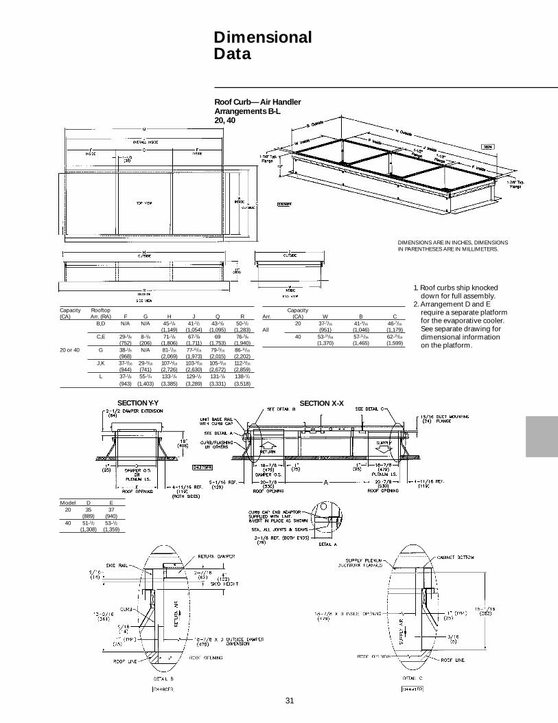
Roof Curb— Air HandlerArrangements B-L20, 40
DIMENSIONS ARE IN INCHES, DIMENSIONSIN PARENTHESES ARE IN MILLIMETERS.
CapacityArr. (CA) W B C
20 37-7/16 41-3/16 46-7/16
All (951) (1,046) (1,179)40 53-15/16 57-11/16 62-15/16
(1,370) (1,465) (1,599)
Capacity Rooftop(CA) Arr. (RA) F G H J Q R
B,D N/A N/A 45-1/4 41-1/2 43-1/8 50-1/2(1,149) (1,054) (1,095) (1,283)
C,E 29-5/8 8-1/8 71-1/8 67-3/8 69 76-3/8(752) (206) (1,806) (1,711) (1,753) (1,940)
20 or 40 G 38-1/8 N/A 81-7/16 77-11/16 79-5/16 86-11/16
(968) (2,069) (1,973) (2,015) (2,202)J,K 37-3/16 29-3/16 107-5/16 103-9/16 105-3/16 112-9/16
(944) (741) (2,726) (2,630) (2,672) (2,859)L 37-1/8 55-1/4 133-1/4 129-1/2 131-1/8 138-1/2
(943) (1,403) (3,385) (3,289) (3,331) (3,518)
Model D E20 35 37
(889) (940)40 51-1/2 53-1/2
(1,308) (1,359)
SECTION Y-Y SECTION X-X
1. Roof curbs ship knockeddown for full assembly.
2. Arrangement D and Erequire a separate platformfor the evaporative cooler.See separate drawing fordimensional informationon the platform.
32
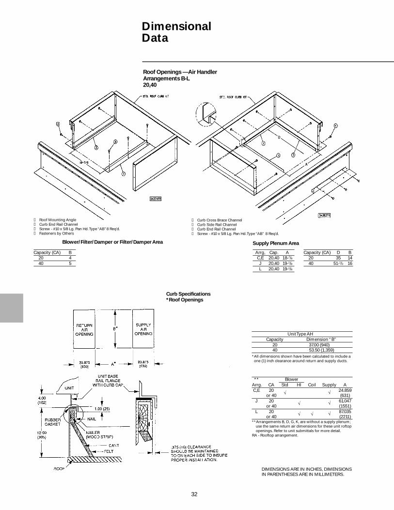
DimensionalData
Roof Openings —Air HandlerArrangements B-L20,40
Unit Type AHCapacity Dimension “B”
20 37.00 (940)40 53.50 (1,359)
*All dimensions shown have been calculated to include a one (1) inch clearance around return and supply ducts.
** BlowerArrg. CA Std HI Coil Supply A C,E 20 Ö Ö 24.859
or 40 (631) J 20 Ö Ö 61.047
or 40 (1551) L 20 Ö Ö Ö 87.035
or 40 (2211)**Arrangements B, D, G, K, are without a supply plenum;
use the same return air dimensions for these unit roftopopenings. Refer to unit submittals for more detail.
RA - Rooftop arrangement.
Curb Specifications*Roof Openings
DIMENSIONS ARE IN INCHES, DIMENSIONSIN PARENTHESES ARE IN MILLIMETERS.
Capacity (CA) B20 440 5
Arrg, Cap. AC,E 20,40 18-7/8J 20,40 19-1/8L 20,40 19-1/8
Capacity (CA) D B20 35 1440 51-1/2 16
Blower/Filter/Damper or Filter/Damper Area Supply Plenum Area
➀ Curb Cross Brace Channel➁ Curb Side Rail Channel➂ Curb End Rail Channel➃ Screw - #10 x 5/8 Lg. Pan Hd. Type “AB” 8 Req’d.
➀ Roof Mounting Angle➁ Curb End Rail Channel➂ Screw - #10 x 5/8 Lg. Pan Hd. Type “AB”8 Req’d.➃ Fasteners by Others

33
DimensionalData
Unit/Curb End Rail Assembly
Curb Cap End Adaptor -Supplied with the Unit(one each end)
Unit/Base Rail Assembly
Evaporative Cooler Curb/Platform Mounting Assembly
See View A
View ATyp. (8) PLC’s.
Evaporative CoolerCurb/Platform 20, 40
➀ Evaporative Cooler Assembly➁ Curb➂ 1/4-20 “KEPS” Nut (8) Required➃ 1/4-20 x 5/8 Lg. Hex Hd. Bolt (8) Required
34
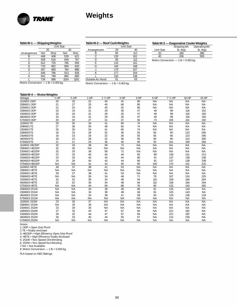
Table W-1 — Shipping WeightsUnit Size
20 40Arrangement Net Ship Net Ship
B 406 408 529 621C 509 616 649 767D 612 725 785 909E 715 852 905 920G 567 680 764 888J 649 786 913 928K 652 789 865 880L 734 896 1014 1191
Metric Conversion — 1 lb = 0.453 kg.
Table W-4 — Motor WeightsVoltage 1/2 HP 3/4 HP 1 HP 1 1/2 HP 2 HP 3 HP 5 HP 7 1/2 HP 10 HP 15 HP115/60/1 ODP 20 25 25 40 42 80 NA NA NA NA208/60/1 ODP 21 27 25 40 66 80 NA NA NA NA230/60/1 ODP 21 25 25 40 42 80 NA NA NA NA208/60/3 ODP 20 24 31 29 35 47 49 99 118 152230/60/3 ODP 20 24 31 29 35 47 49 99 118 150460/60/3 ODP 20 24 31 29 35 47 49 99 118 150575/60/3 ODP 20 20 27 31 37 56 73 105 116 150115/60/1 TE 26 30 34 41 65 74 NA NA NA NA208/60/1 TE 27 36 39 48 65 74 NA NA NA NA230/60/1 TE 26 30 34 41 65 74 NA NA NA NA208/60/3 TE 18 23 28 32 36 55 65 90 123 295230/60/3 TE 18 23 28 32 36 55 65 90 123 295460/60/3 TE 18 23 28 32 36 55 65 90 123 295575/60/3 TE 21 21 26 36 40 90 92 161 199 284115/60/1 HEODP 32 33 38 58 72 NA NA NA NA NA208/60/1 HEODP 32 30 NA NA NA NA NA NA NA NA230/60/1 HEODP 32 33 38 58 72 NA NA NA NA NA208/60/3 HEODP 22 25 40 44 44 83 89 139 141 213230/60/3 HEODP 24 26 40 43 44 80 91 137 138 238460/60/3 HEODP 24 26 40 43 44 80 91 137 138 238575/60/3 HEODP NA NA 41 44 45 90 100 170 141 215115/60/1 HETE 28 37 38 41 53 NA NA NA NA NA208/60/1 HETE NA NA NA NA NA NA NA NA NA NA230/60/1 HETE 28 37 38 41 53 NA NA NA NA NA208/60/3 HETE NA NA 39 34 48 71 78 107 124 225230/60/3 HETE 32 52 39 34 48 94 110 158 166 294460/60/3 HETE 32 52 39 34 48 94 110 158 166 294575/60/3 HETE NA NA 44 69 88 76 80 132 140 260208/60/3 2S1W NA NA 34 38 48 66 81 125 143 NA230/60/3 2S1W NA NA 34 38 48 66 81 125 143 NA460/60/3 2S1W NA NA 34 38 41 58 94 125 136 218575/60/3 2S1W NA NA NA NA NA NA NA NA NA NA115/60/1 2S2W 23 30 37 NA NA NA NA NA NA NA208/60/1 2S2W NA 29 36 NA NA NA NA NA NA NA230/60/1 2S2W 23 29 36 NA NA NA NA NA NA NA208/60/3 2S2W 27 32 44 47 67 84 NA 221 192 NA230/60/3 2S2W 26 32 44 47 67 84 NA 221 192 NA460/60/3 2S2W 26 33 40 44 55 67 NA 214 230 NA575/60/3 2S2W NA NA NA NA NA NA NA NA NA NA
Notes:1. ODP = Open Drip Proof2. TE = Totally enclosed3. HEODP = High Efficiency Open Drip Proof4. HETE = High Efficiency Totally Enclosed5. 2S1W = Two Speed One Winding6. 2S2W = Two Speed Two Winding7. NA = Not Available8. Metric Conversion — 1 lb = 0.453 kg.
FLA based on NEC Ratings
Weights
Table W-3 — Evaporative Cooler WeightsShipping Wt. Operating Wt.
Unit Size lb. (Kg) lb. (Kg)20 166 38640 206 509
Metric Conversion — 1 lb = 0.453 kg.
Table W-2 — Roof Curb WeightsUnit Size
Arrangement 20 40B 85 112C 133 161D 85 112E 133 161G 140 168J 179 207K 177 204L 210 238
Outside Air Hood 51 63
Metric Conversion — 1 lb = 0.453 kg.

35
Options
Trane rooftop packaged air handlershave the following design features:
• ETL and CSA UL-1995 certified.
• Units are completely wired, tested andrail-mounted with blower drives preset.
• Draw-thru cooling coil cabinetarrangements with stainless steel drainpan.
• Evaporative cooling arrangement withstandard 8 or optional 12-inch media(203 or 305 mm).
Remote Control Station(Order No. 134-0201-01)
• Wall mounted• Six LED status lamps• System on/off, fan auto/on, heat auto/
off, cool auto/off, auxiliary on/offswitching and modulating damperpotentiometer mounting.
• Plug-in terminal block wiring and wallmounting bracket.
• 6 1/4” W x 3 3/4” H x 1 1/2” D
Roof CurbsRoof curbs are available for all Tranepackaged air handlers offered in thiscatalog. All curbs are shipped knockeddown for field assembly. Curbs arenormally available on a short lead timebasis so that they may be on thejobsite well in advance of the units.Curbs are 12 inches high, factoring inthe four-inch unit base rail, overallheight to the bottom of the rooftopunit is actually 16 inches. Roof curbscan be supplied with one-inchfiberglass insulation.
Seven-Day Timeclock(Order No. 134-0201-02)
• Single pole double throw (SPDT) relayoutput at setpoint time
• Maximum of six setpoints per day• 7 3/4” H x 5” W x 3 7/16” D
24-Hour Timeclock(Order No. 134-0201-03)
• Single pole double throw (SPDT) relayoutput at setpoint time.
• Maximum 12 setpoints per day.• 7 3/4” H x 5” W x 3 7/16” D
FeaturesSummary

36
MechanicalSpecifications
Arrangements B-L
GeneralUnits shall be completely factoryassembled, wired and test fired. Unitsshall be mounted on metal rails withlifting and anchor holes and shall besuitable for slab or curb mounting. Allunits shall be ETL or UL certified forelectrical safety in compliance with UL1995 safety standard for heating,ventilating and cooling equipment.
ElectricalStandard control relays shall be socketmounted with terminal blockconnections. All control wiring shallterminate at terminal strips (singlepoint connection) and include anidentifying marker corresponding tothe wiring diagram. Motor and controlwiring shall be harnessed with terminalblock connections.
CasingCasings shall be die-formed, 18-gaugegalvanized steel and finished in air-dryenamel. Service and access panelsshall be provided through easilyremovable side access panels withcaptive fasteners. Fan sections andsupply plenums (when provided) shallbe insulated with fire resistant,odorless, matte-faced one-inch glassfiber material. Outside air hoods, whenprovided, ship with a wire mesh inletscreen.
Evaporative Cooler (Standard onArrangement D and E only)An evaporative cooler with 8-inchmedia shall be provided. Theevaporative cooler shall be of a self-cleaning design with a stainless steelwater tank, regulated water flow andoverflow protection. The cooler shallhave a cabinet assembly of heavy-gauge aluminized steel withweatherproof finish, a UL recognizedthermally protected sealedrecirculating pump motor, two-inchdistribution pad, and corrosionresistant PVC water distribution tubes.
Cooling Coil Section (Standard onArrangement K and L only)A cooling coil section, constructed ofgalvanized steel, shall be provided withthe unit. This section shall be insulatedwith fire resistant, odorless, matte-faced one-inch glass fiber material.
FansCentrifugal fan shall be belt-driven,forward curved with double inlet,statically and dynamically balanced.The blower wheel shall be fixed on akeyed shaft, supported with rubbergrommet on bearing only and ballbearing secured. 7 1/2 through 15 hpmotors are equipped with a pillowblock bearing assembly on the driveside. An access interlock switch shall beinstalled in the blower compartmentand will disengage the blower uponremoving the service panel. Anoverride shall be incorporated into theinterlock switch for serviceability.
FiltersFilter rack shall be constructed ofgalvanized steel with access throughthe side service panel. Standard filtersare one-inch permanent washable type(Arrangement B-E).
OR
Filter rack shall be of v-bank design forminimal pressure drop and beconstructed of galvanized steel withaccess through the side service panel.Standard filters are one-inchpermanent washable type(Arrangement G-L).
Electrical CabinetElectrical cabinet shall be isolated fromthe airstream with a non-removableaccess panel interior to the outerservice panel. There is provision in thiscabinet for component mounting, wirerouting and high voltage isolation.Motor and control wiring shall beharnessed with terminal blockconnections.
ControlsAll rooftop units shall be provided witha low voltage circuit breaker rated for150 percent of the units normal 24-voltoperating load.
Factory Installed Options
Motors — GeneralAll motors shall be ball bearing typewith resilient base mount and NEMAframe sizes from 48 to 256T. Windingsare Class “B”, 1800 rpm with servicefactors of 1/2 - 3/4 hp = 1.25 and 1 - 15 hp= 1.15.
Single-Speed Open Drip-proof60 HZ/1800 RPMSingle-Phase (with contactor) —Optional 115V, 208V and 230V motorsavailable in 1/2 - 2 hp models.
Three-Phase (with contactor) —Optional 208V, 230V and 460V motorsavailable in 1/2 - 5 hp models.
Single-Phase (with magnetic starter) —Optional 115V, 208V and 230V motorsavailable in 1/2 - 3 hp models.
Three-Phase (with magnetic starter) —Optional 208V, 230V, 460V and 575Vmotors available in 1/2 - 15 hp models.
Single-Speed TEFC60HZ/1800 RPMSingle-Phase (with contactor) —Optional 115V, 208V and 230V motorsavailable in 1/2 - 1 1/2 hp models.
Single-Phase (with magnetic starter) —Optional 115V, 208V and 230V motorsavailable in 1/2 - 3 hp models.
Three-Phase (with magnetic starter) —Optional 208V, 230V, 460V and 575Vmotors available in 1/2 - 15 hp models.
Single-Speed High Efficiency ODP60 HZ/1800 RPMSingle-Phase (with contactor) —Optional 115V and 230V motorsavailable in 1/2 - 1 hp models. Optional208V motors available in 1/2 - 3/4 hpmodels.
Single-Phase (with magnetic starter) —Optional 115V and 230V motorsavailable in 1/2 - 2 hp models. Optional208V motors available in 1/2 - 3/4 hpmodels.
Three-Phase (with magnetic starter) —Optional 208V, 230V and 460V motorsavailable in 1/2 -15 hp models. Optional575V motors available in 1 - 15 hpmodels.

37
MechanicalSpecifications
Single-Speed High Efficiency TEFC60 HZ/1800RPMSingle-Phase (with contactor) —Optional 115V and 230V motorsavailable in 1/2 - 1 1/2 hp models.
Single-Phase (with magnetic starter) —Optional 115V and 230V motorsavailable in 1/2 - 2 hp models.
Three-Phase (with magnetic starter) —Optional 230V and 460V motorsavailable in 1/2 - 15 hp models. Optional208V and 575V available in 1 - 15 hpmodels.
Two-Speed/One Winding Motors(Three-Phase Only)60 HZ/1800/900 RPMThree-Phase (with magnetic starter) —Optional 208V, 230V and 460V motorsavailable in 1 - 15 hp models.
Two-Speed/Two Winding Motors60 HZ/1800/1200 RPMSingle-Phase (with magnetic starter) —Optional 115V and 230V motorsavailable in 1/2 - 1 hp models. Optional208V motors available in 3/4 - 1 hpmodels.
Three-Phase (with magnetic starter) —Optional 208V and 230V motorsavailable in 1/2 - 15 hp models. Optional460V motors available in 1/2 - 3 hp and7 1/2 - 10 hp models. Optional 575Vmotors available in 7 1/2 - 10 hp models.
Manual Blower SwitchManual blower switch shall be factoryinstalled in the electrical cabinet.
DX or Chilled Water Cooling CoilsAvailable on arrangement K and L only.A direct expansion (DX) or chilledwater coil certified by ARI shall beprovided with the unit.
Damper OptionsDampers shall be of the opposed bladetype, constructed of galvanized steelwith neoprene nylon bushings, bladesto be mechanically interlocked.Optional low leak outside air dampersshall be of the opposed blade type,construction of galvanized steel withneoprene nylon bushings and vinylblade edge seals, blades to bemechanically interlocked.
Outside Air or Return Air/ Two- PositionMotor/ Spring Return
Units with outside air or return air onlyshall be provided with damper, two-position spring return damper motorand controls. The motor shall power thedamper full open when the unit is onand full closed when the unit is off.
OA/RA Two-Position Spring ReturnTwo-position spring return motor withinterlocked outside and return airdampers shall be provided. The motorshall power either the outside airdamper full open and the return airdamper full closed or the outside airdamper full closed and the return airdamper full open in response to anoutside air temperature sensor.(Includes an outside air thermostat thatmakes on a rise in temperature anddrives the damper open.) When theunit is off, the motor will drive theoutside air damper full closed and thereturn air damper full open.
OA/RA Mod Motor with Mixed AirControl/Min. Pot/Spring ReturnModulating motor with interlockedoutside and return air dampers shall beprovided. The motor shall modulate theposition of the outside and return airdampers in response to a thermostaticcontroller located in the mixed airstream. Units shall also be providedwith a minimum positionpotentiometer for minimum outside airdamper position.
The spring return feature drives theoutside air damper full closed and thereturn air damper full open when theunit is off.
OA/RA Mod Motor with Mixed AirControl/Spring ReturnModulating motor with interlockedoutside and return air dampers shall beprovided. The motor shall modulate theposition of the outside and return airdampers in response to a thermostaticcontroller located in the mixed airstream.
The spring return feature drives theoutside air damper full closed and thereturn air damper full open when theunit is off.
OA/RA Mod Motor with Min Pot/Spring ReturnModulating motor with interlockedoutside and return air dampers shall beprovided. The motor shall position theoutside and return air dampers inresponse to a manually setpotentiometer.
The spring return feature drives theoutside air damper full closed and thereturn air damper full open when theunit is off.
OA/RA Mod Motor with Dry Bulb/Mixed Air Control/Min Pot/Spring ReturnModulating motor with interlockedoutside and return air dampers shall beprovided. The motor shall modulate theposition of the outside and return airdampers in response to a thermostaticcontroller and dry bulb thermostatlocated in the mixed airstream. Unitsshall also be provided with a minimumposition potentiometer for minimumoutside air damper position.
The spring return feature drives theoutside air damper full open and thereturn air damper full closed when theunit is off.
OA/RA Mod Motor with EnthalpyControlled Economizer/Spring ReturnModulating motor with spring returnand interlocked outside and return airdampers shall be provided. The motorshall modulate the position of theoutside and return air dampers inresponse to an enthalpy controlledeconomizer. When the unit is off, themotor will drive the outside air damperfull closed and the return air damperfull open.
OA/RA Mod Motor with SpacePressure ControllerModulating motor with spring returnand interlocked outside and return airdampers shall be provided. The motorshall modulate the position of theoutside and return air dampers inresponse to a pressure sensor locatedin the building.

38
OA/RA Mod Mtr with S-350PProportional Mixed Air Control/Spring ReturnModulating motor with spring returnand interlocked outside and return airdampers shall be provided. The motorshall modulate the position of theoutside and return air dampers inresponse to a solid-state mixed airsensor and S-350 Proportionalcontroller. When the unit is off, themotor will drive the outside air damperfull closed and the return air damperfull open.
OA/RA Mtr. with External 4-20 mA or 0-10 VDC Analog Input/Spring ReturnModulating motor interlocked withoutside and return air dampers shall beprovided. The motor shall modulate theposition of the outside and return airdampers in response to a 4-10 mA or 0-10 VDC signal supplied by an externalDDC controller.
The spring return feature drives theoutside air damper full closed and thereturn air damper full open when theunit is shut down.
ASHRAE Cycle I (OA/RA Two- Positionwith Warm-up Stat/SR)Two-position spring return motor withinterlocked outside and return airdampers shall be provided. The motorshall power the outside air damper fullopen after a warm-up perioddetermined by a minimum supply airtemperature sensor when the unit ison, and full closed when the unit is off.
ASHRAE Cycle II OA/RA Mod withWarm-up Stat/Mixed Air/Min Pot/Spring ReturnModulating motor with interlockedoutside and return air dampers shall beprovided. The motor shall modulate theposition of the outside and return airdampers in response to a thermostaticcontroller located in the mixed airstream after a warm-up perioddetermined by a minimum supply airtemperature sensor. Units shall also beprovided with a minimum positionpotentiometer for minimum outside airdamper position. When the unit is off,the motor will drive the outside airdamper full closed and the return airdamper full open.
ASHRAE Cycle III OA/RA Mod. withWarm-up Stat/Mixed Air/SRModulating motor with spring returnand interlocked outside and return airdampers shall be provided. The motorshall modulate the position of theoutside and return air dampers inresponse to a thermostatic controllerlocated in the mixed airstream after awarm-up period determined by aminimum supply air temperaturesensor. When the unit is off, the motorwill drive the outside air damper fullclosed and the return air damper fullopen.
Manual DampersUnits with outside air and return airshall be provided with manually setoutside and return air dampers.
Additional Factory Installed OptionsFirestatIf temperature reaches the setpoint, thedampers will return to their normalposition and shut down the blower.Manual reset.
Return Air Mounted (setpoint typically130 F)
Supply Air Mounted (setpoint typically150 F)
FreezestatUnit shall be provided with a freezestat(0-100 F) with the sensing bulb locatedin the discharge airstream. Wired as aninterlock to prevent cold air discharge.
12-inch Evaporative Media12-inch media shall be provided for theevaporative cooler.
Double Wall ConstructionThe construction will consist of a 24-gauge inner liner wall with 1-inch 1½lb. density insulation. Access doors onthe specified side will be hinged and ofthe same double wall design. Doublewall is not available on the applicableevaporative cooler and furnacesections. Double wall construction willbe provided by the manufacturer onapplicable filter/damper, blower, coiland plenum cabinets.
Clogged Filter SwitchA clogged filter pressure switch withadjustable operating range andnormally open switch shall be installedto sense increased suction pressure bythe blower due to filter obstruction.Provision for remote indication shall beprovided by terminal block connectionpoints. Includes a status lamp mountedin the electrical cabinet.
Moisture EliminatorsProvided in place of an inlet screen onthe outside air hood. Includes apressure switch.
Horizontal ReturnUnit shall be supplied with the returnair opening at or under the outside airopening location depending on the airinlet configuration.
Continuous Fan Relay — 24V CoilDPDT 10ARelay provided with 24-volt coil anddouble pole double-throw 10-ampcontacts. Plugs into the mainconnection PC board in the electricalcabinet. Included as standard onArrangement D and E. May also beutilized as an exhaust fan interlock.
Interlock Relay — 24/115V Coil SPDT10ARelay has a selectable coil voltage of 24or 115 volts and single-pole doublethrow 10-amp contacts with LED onindicator lamp. Relay is utilized as anauxiliary relay.
Interlock Relay — 24/115-230V CoilDPDT 10ARelay has a selectable coil voltage of24, 115 or 230-volts and double poledouble throw 10-amp contacts. Utilizedas an auxiliary relay for generalpurpose duty.
Ambient Lockout
Airflow proving switch
Hinged Service Access DoorsOptional hinged doors are mounted tothe access side of the standard blower/filter/damper cabinet and high CFMfilter/damper and blower cabinets inleau of the standard removable accessdoors. The hinged doors include dualquick opening tool-less latches and fullperimeter gasketing to assure a watertight seal and door stops to guardagainst closure while open. Theremaining Duct Furnace(s), supplyplenum cabinets (if applicable) aresupplied with a standard removabledoor. The coil cabinet door utilizes aspecial removable vertical split doorallowing for coil access and unitpenetration for coil connections.
MechanicalSpecifications

39
MechanicalSpecifications
Evaporative Cooler
GeneralAn evaporative cooler with eight-inchmedia shall be provided. Theevaporative cooler shall be of a self-cleaning design with a stainless steelwater tank, regulated water flow andoverflow protection. The cooler shallhave a cabinet assembly of heavy-gauge aluminized steel withweatherproof finish, a UL recognized,thermally protected sealedrecirculating pump motor, two-inchdistribution pad, and corrosionresistant PVC water distribution tubes.
Factory Installed Options12-Inch Evaporative Media12-inch media shall be provided for theevaporative cooler.
Field Installed AccessoriesEvaporative Cooler PlatformProvides mounting support forevaporative cooler only
Fill and Drain KitIncludes three-way valve and relay andautomatic fill and drain for theevaporative cooler.
FreezestatFreezestat provides automatic shutoffand drain upon meeting outside airsetpoint.
Field Installed AccessoriesRemote Control StationWall mounted. Provides six LED statuslamps with System On/Off, Fan Auto/On, Heat Auto/Off, CoolAuto/Off,Auxiliary On/Off switching andmodulating damper potentiometermounting. Designed for easyinstallation with plug-in terminal blockwiring and wall mounting bracket.(Auxiliary On/Off may be used withthe evaporative cooler fill and drainkit)
Seven-Day TimeclockProvides single-pole double-throw(SPDT) relay output at setpoint timewith maximum six setpoints per day.
24-Hour TimeclockProvides single-pole double-throw(SPDT) relay output at setting timewith maximum 12 setpoints per day.
Disconnect Switch
115V Convenience OutletGFI (Ground Fault ConvenienceOutlet) is manual reset withweatherproof enclosure. (Requiresseparate 115V power supplied.)
Roof Mounting CurbInsulated roof curb shall be shippedunassembled with hardware packageand gasket attached. Curb and railshall total 16 inches high and suppliedwith a cross-member which allowsthe isolation of the return and supplyair streams (when supplied).
Evaporative Cooler PlatformProvides mounting support forevaporative cooler only.
Fill and Drain KitIncludes three-way valve and relay forautomatic fill and drain for theevaporative coolers. Optionalfreezestat provides automatic shutoffand drain upon meeting outside airsetpoint.
Optional Filters (One-inch permanentstandard)
Two-inch Permanent
Two-inch Throwaway
One-inch 30 percent Pleated Media
Two-inch 30 percent Pleated Media
Thermostats
Low voltage room thermostat, single-stage with fan auto-on-switch andsystem heat-off cool switch
Low voltage room thermostat, single-stage with fan auto-on switch
Low voltage room thermostat, two-stage with fan auto-on switch andsystem off-heat-auto-cool switch
Low voltage programmable roomthermostat, two-stage with LCDdisplay, fan auto-switch an system off-heat-auto-cool switch
Universal tamperproof guard for allroom thermostats
Low voltage duct thermostat, single-stage
Low voltage duct thermostat, two-stage
Room thermostat, electronicmodulating control
Duct thermostat, electronic modulatingcontrol
Duct thermostat, electronic modulatingcontrol with override room thermostat

Library Product Literature
Product Section Air Handling
Product Make-Up Air
Model 000
Literature Type Data Sales Catalog
Sequence 4
Date February 1998
File No. PL-AH-MUA-000-DS-4-298
Supersedes MUA-DS-4 695
Ordering No. MUA-DS-4
The Trane Company2701 Wilma Rudolph Blvd.Clarksville, TN 37040www.trane.com
An American Standard Company
The Trane Company has a policy of continuousproduct and product data improvement, itreserves the right to change product design andspecifications without notice.