packaged air cooled water chiller type...
TRANSCRIPT
BULLETIN NO. IM 172JULY 1978
INSTALLATION ANDMAINTENANCE DATA
PACKAGED AIR COOLED WATER CHILLER
TYPE ALR-060 THRU 130A
GROUP McQuay-PERFEX Inc. 13600 Industrial Park Blvd., P.O. Box 1551, Minneapolis, Mn. 55440 @
TABLE OF CONTENTS
INTRODUCTION ................................................... .NOMENCLATURE ................................................... .PRE-INSTALLATION ............................................... .INSTALLATION ............................................... ..4- 7
HANDLING ................................................... .LOCATION ................................................... .ACCESS FOR SERVICING ................................... ..5- 6VIBRATION ISOLATORS .................................... ..6- 7
WATER PIPING ............................................. .-.8-l 0PIPING PRACTICES ........................................... .CHILLED WATER THERMOSTAT ............................... ..8- 9FLOW SWITCH ................................................ .PIPING CONNECTIONS ...................................... ..10
FIELD WIRING ............................................. ..11-13START-UP AND SHUT-DOWN ................................... ..13-16ELECTRICAL ............................................... ..16-4 7
CONTROL CENTER ...................................... .-.16-l 7CONTROL PANEL LAYOUTS ................................... ..17ELECTRICAL LEGEND ....................................... ..18SEQUENCE OF OPERATION ................................ ..18-19PUMPDOWN CYCLE .......................................... ..19MAJOR COMPONENT LOCATIONS ............................... ..2 0WIRING SCHEMATICS .................................... ..21-3 9DESCRIPTION OF UNIT CONTROLS ......................... ..40-4 7
UNIT MAINTENANCE ......................................... ..47-5 1GENERAL ................................................. ..4 7REFRIGERANT SIGHT GLASS ................................. ..4 7FILTER-DRIERS ........................................... ..4 7LIQUID LINE SOLENOID VALVE .............................. ..4 8THERMOSTATIC EXPANSION VALVE ......................... ..48-4 9EVAPORATOR ........................................... ..49-5 0CONDENSERS .............................................. ..5 0COMPRESSOR WEAR AND LEAD-LAG ............................ ..5 0COMPRESSOR OIL LEVEL .................................... ..5 0FAN BELT TENSION ........................................ ..5 1FAN SHAFT BEARINGS ...................................... ..5 1FAN MOTOR BEARINGS ...................................... ..5 1ELECTRICAL TERMINALS .................................... ..5 1
IN WARRANTY RETURN MATERIAL PROCEDURE ....................... ..5 1TROUBLE SHOOTING CHART ...................................... ..5 2
Page 2

INTRODUCTION
McQuay type ALR Seasonpak air cooled water chillers are complete selfcontained automatic refrigerating units that include the latest inengineered components arranged to provide a compact and efficientunit. Each unit is completely assembled and factory wired beforeevacuation, charging and testing, and comes complete and ready forinstallation. Each unit consists of: twin air cooled condenserswith integral subcooler sections, multiple accessible hermetic com-pressors, replaceable tube dual circuit shell and tube evaporator,and complete refrigerant piping. Liquid line components that areincluded are: manual liquid line shutoff valves, replaceable corefilter driers, liquid line solenoid valves, sight glass/moisture in-dicators, and double diaphragm hydraulic element thermal expansionvalves. Other features include: compressor crankcase heaters, anevaporator heater for chilled water freeze protection, recyclingpumpdown during "on" or "off" seasons, compressor lead lag switch toalternate the compressor starting sequence, and sequenced startingof compressors.
The electrical control center includes all safety and operating con-trols necessary for dependable automatic operation. Each compressorand fan motor is fused in all three conductor legs and started by itsown three pole contactor.
NOMENCLATURE
RECIPROCATING COMPRESSORSLOW POWER CONSUMING
11AIR COOLED CONDENSER -ItA L R - 0 8 5 A D
DUAL REFRIGERANT CIRCUITSDESIGN VINTAGENOMINAL C AP ACI TY (TONS )
PRE-INSTALLATION
Inspection
When the equipment is received, all items should be carefully checkedagainst the bill of lading to insure a complete shipment. All unitsshould be carefully inspected for damage upon arrival. All shippingdamage should be reported to the carrier and a claim should be filed.The unit serial plate should be checked before unloading the unit tobe sure that it agrees with the power supply available.
Page 3
INSTALLATION
Handling
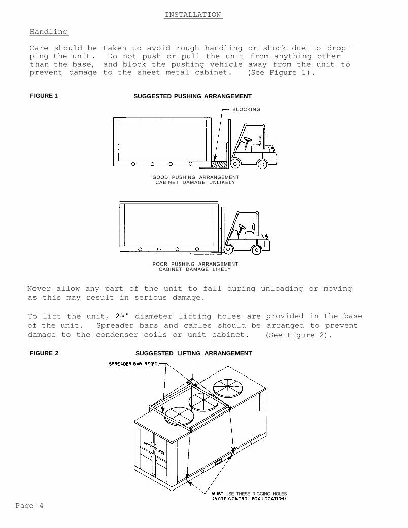
Care should be taken to avoid rough handling or shock due to drop-ping the unit. Do not push or pull the unit from anything otherthan the base, and block the pushing vehicle away from the unit toprevent damage to the sheet metal cabinet. (See Figure 1).
FIGURE 1 SUGGESTED PUSHING ARRANGEMENT
7 BLOCKING
GOOD PUSHING ARRANGEMENTCABINET DAMAGE UNLIKELY
POOR PUSHING ARRANGEMENTCABINET DAMAGE LIKELY
Never allow any part of the unit to fall during unloading or movingas this may result in serious damage.
To lift the unit, 2%" diameter lifting holes are provided in the baseof the unit. Spreader bars and cables should be arranged to preventdamage to the condenser coils or unit cabinet. (See Figure 2).
FIGURE 2 SUGGESTED LIFTING ARRANGEMENT
SPRE:ADER
Page 4
‘LMUST USE THESE RIGGING HOLES(NOTE CONTROL Box LOCATION)

Location
Due to the vertical condenser design, it is recommended that certainprecautions be taken before installation to orient the unit so thatprevailing winds blow parallel to the unit length thus minimizinqeffects on condensing pressure. If it is not practical to orientthe unit in this manner, a wind deflecting fence should be consi-dered.
It is also necessary to provide adequate clearance on all sides ofthe unit for service access and satisfactory performance. At least60 in. (1 fan diameter) should be allowed on each side of the unitfor condenser air inlet and compressor removal on units 060 & 065.If parallel units are installed side by side, 120 in. should beallowed between units. This will prevent excessive condensingtemperatures and enhance system performance and operating economy.Clearance for service access should be at least 78 in. at thecontrol center end for compressor removal on units 075 thru 130and sufficient at the end opposite the control center for evapora-tor tube replacement. These clearances are illustrated in Figure 3.
FIGURE 3 CLEARANCE AROUND UNIT
60” MINIMUM-CLEARANCEFOR AIR INLET
11 I I4
60” MINIMUM CLEARANCEFOR AIR INLET AND COMPRESSOR
REMOVAL ON ALR-060,065h
NOTE: Minimum vertical clearance above unit should be 10 feet
Access for Servicing
Each end of the unit must be accessible after installation for peri-odic service work. Compressors, filter driers, and manual liquidline shutoff valves are accessible from the control center end of theunit through removable access panels on unit sizes 075 thru 130 andhinged side access doors on unit sizes 060 and 065. All operational,safety, and starting controls are located in the unit control center.They are protected by a keylocked, weatherproof enclosure which con-tains internal "dead front" doors for protection of service person-nel from high voltage starting controls while servicing low voltageoperational controls. All resettable or adjustable controls arelocated just below the main control center. There is one resettablecontrol enclosure on each side of the unit and each encl.osure containscontrols for compressors on that side of the unit. Capped connectionsfor field service gauges are also located inside these enclosures. Inaddition, each of these enclosures are removable to improve access tocompressors for field replacement.
Page 5
The condenser fans, motors, and drives are accessible through a walk-in, keylocked access door on units ALR-075 thru 130 or a removableaccess panel on units ALR-060 and 065. The access door or panel islocated at the end of the unit opposite the control center. Expan-sion valves are accessible from the same access door on unit sizes075 thru 130 and from side access doors at the control center endon unit sizes 060 and 065.
An internal fan guard is located below the condenser fans and driveson units 075 thru 130. This guard must be removed to service thefan drives but must always be re-installed when service work is com-plete. On unit sizes 060 and 065, an interlock switch kills powerto condenser fans whenever the access panel is removed for servicework on fans or drives.
CAUTION: Disconnect all power to the unit whileservicing condenser fan drives.
Vibration Isolators
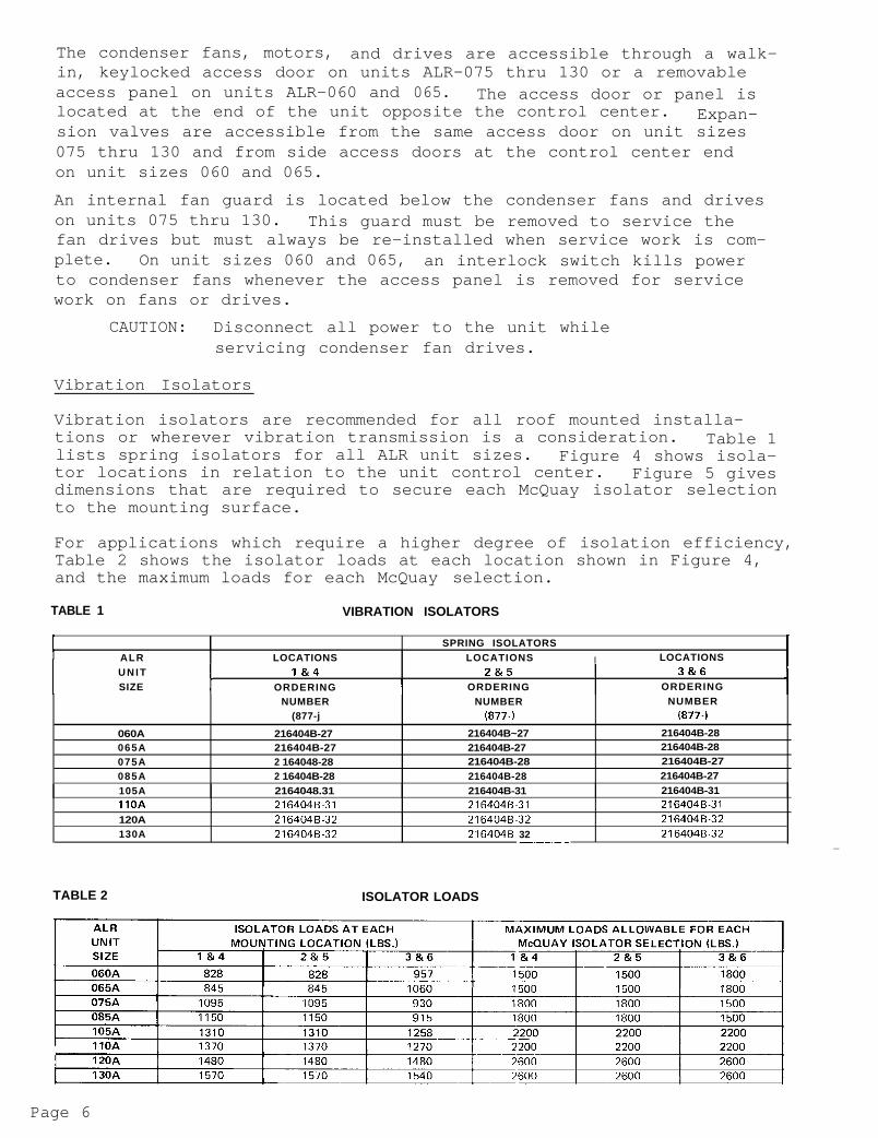
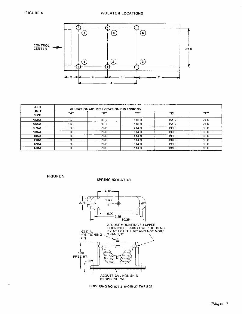
Vibration isolators are recommended for all roof mounted installa-tions or wherever vibration transmission is a consideration. Table 1lists spring isolators for all ALR unit sizes. Figure 4 shows isola-tor locations in relation to the unit control center. Figure 5 givesdimensions that are required to secure each McQuay isolator selectionto the mounting surface.
For applications which require a higher degree of isolation efficiency,Table 2 shows the isolator loads at each location shown in Figure 4,and the maximum loads for each McQuay selection.
TABLE 1 VIBRATION ISOLATORS
I I SPRING ISOLATORSALR LOCATIONS LOCATIONS I LOCATIONSU N I T
tl&4 Z&5 I
I3&6
SIZE ORDERING I ORDERING ORDERING 1NUMBER NUMBER NUMBER
(877-j (877-j (877-i
060A 216404B-27 216404B~27 216404B-28065A 216404B-27 216404B-27 216404B-28075A 2 164048-28 216404B-28 216404B-27085A 2 16404B-28 216404B-28 216404B-27105A 2164048.31 216404B-31 216404B-31IIOA 216404B.31 2164048-31 216404B.31
120A 216404B.32 216404B-32 216404B-32130A 216404B.32 216404B 32 216404B-32__- _
TABLE 2 ISOLATOR LOADS
Page 6
WATER PIPING
Piping Practices
Due to the variety of piping practices, it is advisable to followthe recommendations of local authorities. They can supply the in-staller with the proper building and safety codes required for asafe and proper installation.
Basically, the piping should be designed with a minimum number ofbends and changes in elevation to keep system cost down and perfor-mance up. It should contain:1.
2.
3.
4.
5.
6.
Vibration eliminators to reduce vibration and noise transmissionto the building.Shutoff valves to isolate the unit from the piping system dur-ing unit servicing.Manual or automatic air vent valves at the high points of thesystem.Some means of maintaining adequate system water pressure (e.g.;expansion tank or regulating valve).Temperature and pressure indicators located at the unit to aidin unit servicing.A strainer or some means of removing foreign matter from thewater before it enters the pump. It should be placed far enoughupstream to prevent cavitation at the pump inlet (consult pumpmanufacturer for recommendations). The use of a strainer willprolong pump life and thus keep system performance up.
Prior to insulating the piping and filling the system, a preliminaryleak check should be made.Piping insulation should include a vapor barrier to prevent moisturecondensation and possible damage to the building structure. It isimportant to have the vapor barrier on the outside of the insulationto prevent condensation within the insulation on the cold surfaceof the pipe.
Chilled Water Thermostat
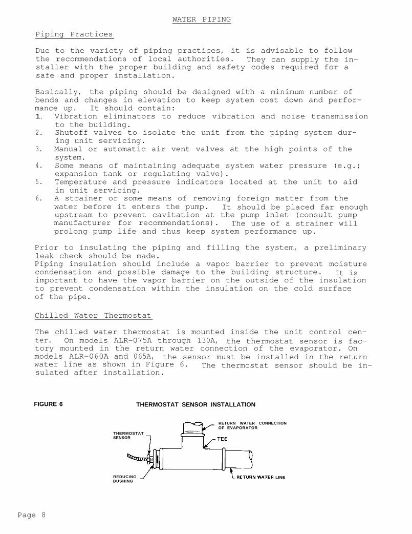
The chilled water thermostat is mounted inside the unit control cen-ter. On models ALR-075A through 130A, the thermostat sensor is fac-tory mounted in the return water connection of the evaporator. Onmodels ALR-060A and 065A,, the sensor must be installed in the returnwater line as shown in Figure 6. The thermostat sensor should be in-sulated after installation.
FIGURE 6 THERMOSTAT SENSOR INSTALLATION
RETURN WATER CONNECTIONOF EVAPORATOR
THERMOSTATSENSOR 7
REDUCING 1 LRETURN WATER LINEBUSHING
Page 8

CAUTION: Thermostats have maximum operating temper-ature limits of:
ALR-060 and 065140F on return water for standard ca-pacity reduction.125F on return water for optional ca-pacity reduction.ALR-075 throuqh 130125F on return water for standard ca-pacity reduction.250F on return water for optional ca-pacity reduction.
Temperatures exceeding these limits may dam-age the controls.
Flow Switch
A WATER FLOW SWITCH MUST BE MOUNTED in either the entering or leav-ing water line to insure that there will be adequate water flow andcooling load to the evaporator before the unit can start. This willsafeguard against slugging the compressors on start up. It alsoserves to shut down the unit in the event that water flow is inter-rupted to guard against evaporator freeze up.
A flow switch is available from McQuay under ordering number 860-175033x-00. It is a "paddle" type switch and adaptable to any pipesize from 1" to 6" nominal. Certain minimum flow rates are requiredto close the switch and are listed in Table 3. Installationshould be as shown in Figure 7.
TABLE 3 FIGURE 7
FLOW SWITCH MINIMUM FLOW RATES
NOMINAL MINIMUM REQUIREDPIPE SIZE FLOW TO ACTIVATE(INCHES) SWITCH (GPM)
1 6.00
1 l/4 9.801 l/2 12.70
2 18.802112 24.30
3 30.004 39.705 58.706 79.20
/FLOW DIRECTION
J’MARKED ON SWITCH
+ FLOW41.00 NPT FLOW SWITCHCONNECTION
5 PIPE DIA. - MINIMUM 5 PIPE DIA. - MINIMUMAFTER SWITCH BEFORE SWITCH
Electrical connections in the unit control center should be made atterminals 11 and 12. The normally open contacts of the flow switchshould be wired between these two terminals. There is also a set of
_ normally closed contacts on the switch that could be used for an in-dicator light or an alarm to indicate when a "no flow" conditionexists.
Page 9

Piping Connections
Water piping connections at the unit vary in size and style depen-ding on the baffle option ordered. These connection variations areshown in the table with Figure 8.
Piping through the unit cabinet can be through the end or bottom ofthe unit as the application dictates. Pilot holes locate the properhole centers for piping through the end of the unit. Figure 8 givesthe necessary dimensions for either piping method.
FIGURE 8
1
A L R DIMENSIONS (INCHES) COOLER I
r\, Y Y Y
060 A D 192 80.0 73.8 36.1 16.3 33.7 24.0
065 A D 192 80.0 73.8 36.1 16.3 33.7 24.0 tib.1075 A D 228 98.8 92.5 47.0 8.0 76.0 30.0 91.4
*COOLER CONNECTIONS - Ail connections are NPS steel pipe. 4 thru 6-inch p ipe connections are furnished with grooves for victauliccouplings by others.
Page 10
FIELD WIRING
Field Wirinq
Wiring should be done in accordance withordinances.
Warranty- -
all applicable codes and
Warranty is voided if wiring is not in accordance with specifica-tions. An open fuse indicates a short, ground, or overload. Beforereplacing a fuse or restarting a compressor or fan motor, the trou-ble must be found and corrected.
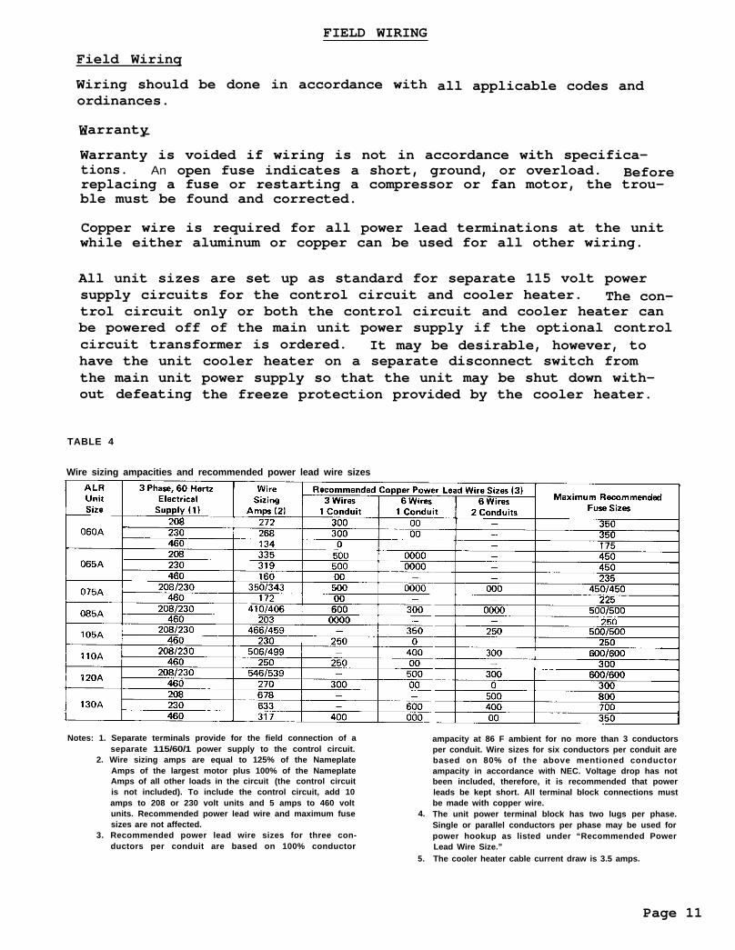
Copper wire is required for all power lead terminations at the unitwhile either aluminum or copper can be used for all other wiring.
All unit sizes are set up as standard for separate 115 volt powersupply circuits for the control circuit and cooler heater. The con-trol circuit only or both the control circuit and cooler heater canbe powered off of the main unit power supply if the optional controlcircuit transformer is ordered. It may be desirable, however, tohave the unitthe main unitout defeating
cooler heater on a separate disconnect switch frompower supply so that the unit may be shut down with-the freeze protection provided by the cooler heater.
TABLE 4
Wire sizing ampacities and recommended power lead wire sizes
Notes: 1. Separate terminals provide for the field connection of aseparate 115/60/1 power supply to the control circuit.
2. Wire sizing amps are equal to 125% of the NameplateAmps of the largest motor plus 100% of the NameplateAmps of all other loads in the circuit (the control circuitis not included). To include the control circuit, add 10amps to 208 or 230 volt units and 5 amps to 460 voltunits. Recommended power lead wire and maximum fusesizes are not affected.
4.
3. Recommended power lead wire sizes for three con-ductors per conduit are based on 100% conductor
5.
ampacity at 86 F ambient for no more than 3 conductorsper conduit. Wire sizes for six conductors per conduit arebased on 80% of the above mentioned conductorampacity in accordance with NEC. Voltage drop has notbeen included, therefore, it is recommended that powerleads be kept short. All terminal block connections mustbe made with copper wire.The unit power terminal block has two lugs per phase.Single or parallel conductors per phase may be used forpower hookup as listed under “Recommended PowerLead Wire Size.”The cooler heater cable current draw is 3.5 amps.
Page 11

A standard feature on all ALR units is COPSTM(Controlled Override ofPump Shutdown), a system for interlocking the field supplied chilledwater pump into the chiller control system. A relay (R-19) is wiredinto the unit control circuit so that a time clock and/or ambientthermostat can be connected to a pair of terminals (6 and 11) in-side the unit control center. The time clock can energize a pumpstarter. Once the pump starts, the flow switch and/or pump inter-lock will close and energize that part of the control circuit thatwill allow the unit to start.
This feature makes it possible to start the chilled water pump andthe chiller simultaneously only when cooling is required. For re-cycling pumpdown without a demand for cooling, a pair of relays(energized by low pressure controls) are also wired into this cir-cuit to start the pump, close the flow switch and pump down theunit.
NOTE: If a time clock, ambient thermostat and/or re-mote on-off switch are not used, terminals 6and 11 must be jumpered together before theunit will start.
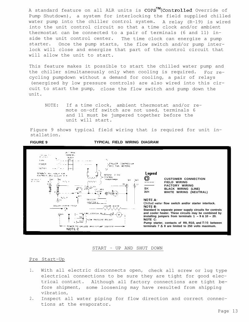
Figure 9 shows typical field wiring that is required for unit in-stallation.
FIGURE 9 TYPICAL FIELD WIRING DIAGRAM
CUSTOMER CONNECTIONFIELD WIRINGFACTORY WIRINGBLACK WIRING (LINE)WHITE WIRING (NEUTRAL)
flow switch and/or starter interlock.
Standard is separate power supply circuits for controlsand cooler heater. These circuits may be combined byinstalling jumpers from terminals 1 - 9 & 10 - 20.NOTE C:Pump starter, contacts of R9, R10, and R19 betweenterminals 7 & 8 are limited to 250 volts maximum.
START - UP AND SHUT DOWN
Pre Start-Up
1. With all electric disconnects open, check all screw or lug typeelectrical connections to be sure they are tight for good elec-trical contact. Although all factory connections are tight be-fore shipment, some loosening may have resulted from shippingvibration,
2. Inspect all water piping for flow direction and correct connec-tions at the evaporator.
Page 13
3.
4.
5.
6.
7.
8.
9.
10.
Open all water flow valves and start the chilled water pump.Check all piping for leaks and vent the air from the evaporatoras well as from the system piping. Flush the evaporator andsystem piping to obtain clean, non-corrosive water in the evap-orator circuit.Check to see that the thermostat water temperature sensor is in-stalled in the return water line (return to chiller). On ALR-075A through 13OA units with standard capacity reduction, orALR-060A and 065A units with standard or optional capacity reduc-tion, the sensor well should be full of heat conducting compoundand the sensor should be secured in the well with the retainingclip provided. On ALR-075A through 130A units with optional cap-acity reduction, the sensor is installed directly into the returnwater line i.e.; no well or heat conducting compound is required.Check the compressor oil level. Prior to start-up, the oil lev-el should cover at least l/2 of the oil sight glass. _Remove the (8) compressor shipping blocks that are attached to thecompressor rails and the base of the unit. The ALR 060 and 065 donot have shipping blocks.Check the voltage of the unit power supply and see that it iswithin the + 10% tolerance that is allowed.balance must be with _+ 2%.
Phase voltage un-
Check the unit power supply wiring for adequate ampacity and aminimum insulation temperature rating of 75C.Verify that all mechanical and electrical inspections have beencompleted per local codes.See that all auxiliary control equipment is operative and thatan adequate cooling load is available for initial start up.
Start-Up
1. Open the compressor suction and discharge shutoff valves until
2.back seated. Always replace valve seal caps.Open the manual liquid line shutoff valve at the outlet of thesubcooler.
3.
4.
5.
Check to see that pumpdown switches (PSl & PS2) are in the "man.pumpdown" position and the control stop switch (Sl) is in the"on " position.Adjust the dial on temperature controller TCl to the desiredchilled water temperature.Throw the main power and control circuit disconnects to the "on"position.
CAUTION: Most relays and terminals in the unitcontrol center are hot with Sl and thecontrol circuit disconnect on.
6.
7.
8.
9.
Allow the crankcase heaters to operate for at least 8 hours priorto start-up.Start the auxiliary equipment for the installation by turningon the time clock, ambient thermostat and/or remote on/off switchif the unit and chilled water pump are electrically interlockedby using the COPS method discussed in "Field Wiring".Start the system by moving pumpdown switches (PSl & PS2) to the"auto. pumpdown" position.After system performance has stabilized, it is necessary that the"Compressorized Equipment Warranty Form" (form no. 206036A) becompleted to obtain full warranty benefits. This form is shippedwith the unit and after completion should be returned to McQuay'sService Department through your sales representative.
Page 14

Temporary Shut-Down
Move pumpdown switches (PSl & PS2) to the "man. pumpdown" position.After the compressors have pumped down, turn off the chilled waterpump.
NOTE: With the unit left in this condition, it iscapable of recycling pumpdown operation. Todefeat this mode of operation, simply movecontrol stop switch (Sl) to the "off" position.
It is important that the compressors pump down before the water flowto the unit is interrupted to avoid freeze up in the evaporator.
Start-Up After Temporary Shut-Down
1. Start the chilled water pump.2. With control stop switch (Sl) in the "on" position, move pump-
down switches (PSl & PS2) to the "auto. pumpdown" position.3. Observe the unit operation for a short time to be sure that the
compressors do not cut out on low oil pressure.
Extended Shut-Down
1. Close the manual liquid line shutoff valves.2. After the compressors have pumped down, turn off the chilled
water pump.3. Turn off all power to the unit and to the chilled water pump.4. Move the control stop switch (Sl) to the "off" position.5. Close the compressor suction and discharge valves.6. Tag all opened disconnect switches to warn against start up be-
fore opening the compressor suction and discharge valves.7. Drain all water from the unit evaporator and chilled water pip-
ing if the unit is to be shut down during winter.
Start-Up After Extended Shut-Down
1.
2.
3.4.cJ.
6.
7.
8.
9.
Inspect all auxiliary equipment to see that it is in satisfac-tory operating condition.Remove all debris that has collected on the surface of the con-denser coils.Open the compressor suction and discharge valves.Open the manual liquid line shut off valves.
Check to see that pumpdown switches (PSl and PS2) are in the man-ual pumpdown position.Turn on the electric power to the unit and other parts of thesystem.Allow the crankcase heaters to operate for at least 8 hoursprior to start-up.Start the chilled water pump and purge the water piping as wellas the evaporator in the unit.Check to see that the control stop switch (S1)is in the "on" posi-tion.
CAUTION: Most relays and terminals in the unitcontrol center are hot with Sl and thecontrol circuit disconnect on.
Page 15
10. Start the unit by moving pumpdown switches (PSl & PS2) to the"auto. pumpdown" position.
11. After running the unit for a short time check the oil level ineach compressor crankcase and check for flashing in the refrig-erant sight glass (see "Maintenance" on Page 47).
ELECTRICAL
Control Center
All electrical controls are enclosed in a weatherproof control cen-ter with keylocked, hinged access doors. The control center is com-posed of three separate enclosures. The upper enclosure is thelargest and contains all of the 208, 230, or 460 volt compressor andfan motor starting controls. Also included in this enclosure butpartitioned separately are the exposed terminal type - 115 volt oper-ational controls. A "dead front" cover over the high voltage sec-tion protects service personnel from high voltage starting controlswhile servicing low voltage operational controls.
Below the upper enclosure are two smaller, separate enclosures thatcontain 115 volt adjustable or resettable controls. There is one ofthese enclosures on each side of the unit, and each contains controlsfor the compressors on that side.
Power supply conduits are intended to come into the bottom of theupper enclosure and between the two lower enclosures. it is recom-mended that the unit disconnect switch be mounted away from the unitbut Figure 10 recommends unit mounting arrangements if the disconnectmust be unit mounted.
Page 16


ELECTRICAL LEGEND
-A-----_--CL
200
\\ABF1F2Ft31,2,3.4FE5FB11,12,13FS1.2HP1.2HPHTRl, thru 4HTR5JBLPI,2LPMl thru 8Ml 1,12,13MPI thru 4OP1,2,3,4OPPBlPC1 and PC2TC5 and TC6PS1.2R3.4R5,6,7.8R9.10R13.14R15, 16R17.18RI9SlS2,3,4TlTD1,2,3,4TD5.6,7.8TD9,lOTD11,12,13NB1.2TB6,7TB5.8.9TClSC1T2T4TC2
FIELD WIRING AND NUMBERED TERMINALOPTIONAL WIRING
FACTORY WIRING AND NUMBERED TERMINAL
WIRE NUMBEROPTIONAL CONTROLS - SEE WI RING DIAGRAMSCONNECTERALARM BELLCONTROL CIRCUIT FUSEEVAPORATOR HEATER FUSEFUSE BLOCKS (COMP. 1,2,3,4)CONTROL CIRCUIT TRANSFORMER FUSE BLOCK - OPTIONALFUSE BLOCKS (COND. FAN 11,12,13)FREEZE CONTROLS (REF. CIRCUIT 1,2)HIGH PRESSURE CONTROLS (REF. CIRCUIT 1,2)HIGH PRESSURE GAUGE -OPTIONALCRANKCASE HEATERS (COMP. 1,2,3,4)EVAPORATOR HEATERJUNCTION BOX (FOR ALARM BELL) - OPTIONALLOW PRESSURE CONTROLS (REF. CIRCUIT 1,2)LOW PRESSURE GAUGE -OPTIONALCONTACTORS (COMP. 1,2,3,4)CONTACTORS (COND. FAN 11,12,13)MOTOR PROTECTORS (COMP. 1,2,3,4)OIL PRESSURE CONTROLS (COMP. 1,2,3,4)01 L PRESSURE GAUGE - OPTIONALMAIN POWER TERMINAL BLOCKFANTROL PRESSURE CONTROLSFANTROL TEMPERATURE CONTROLSPUMPDOWN SWITCHES (REF. CIRCUIT 1.2)STARTER RELAYS (COMP. 3,4)SAFETY RELAYS (COMP. 1,2,3,4)LOW PRESSURE RELAYS (REF. CIRCUIT 1,2)LOW AMBIENT START RELAYS (REF. CIRCUIT 1,2) -OPTIONALCOMPRESSOR LOCKOUT RELAYS - OPTIONALCONDENSER FAN RELAYPUMP STARTER RELAYCONTROL STOP SWITCHLEAD-LAG SWITCHESCONTROL CIRCUIT TRANSFORMER - OPTIONALPART WINDING TIME DELAYS (COMP. 1,2,3,4) -OPTIONALCOMP. LOCKOUT TIME DELAYS (COMP. 1,2,3,4) - OPTIONALLOW AMBIENT START TIME DELAYS (CIRCUIT 1,2) - OPTIONALCOMP. SEQUENCING TIME DELAYS (STAGES 2,3,4)TERMINAL BLOCKS (NEUTRAL-FACTORY WIRING)TERMINAL BLOCKS (HOT-FACTORY WIRING)TERMINAL BLOCKS (FIELD WIRING)WATER TEMP. CONTROL THERMOSTATOPTIONAL WATER TEMP. CONTROL THERMOSTAT SIGNAL CENTEROPTIONAL WATER TEMP. CONTROL THERMOSTAT TRANSFORMERALARM BELL TRANSFORMER - OPTIONALCOOLER HEATER THERMOSTAT
Sequence of Operation
The following sequence of operation is typical for ALR Seasonpak aircooled water chiller operation. It is written for a 4 compressorunit, but where components that apply to the fourth compressor arereferred to, the equivalent components for the third and second com-pressors of a 3 or 2 compressor unit are indicated in parentheses.
Page 18
With the control circuit power on, control stop switch ~1 closed,and manual pumpdown switches PSl and PS2 closed ("Auto" position),115 volt power is applied through control circuit fuse Fl to thecompressor crankcase heaters HTRl through HTR4, (HTR3, HTR2,) andalso to the contacts of low pressure switches LPl and LP2.
When the remote time clock or manual shutdown switch turns "on", COPSTMpump starter relay R19 is energized, closing contacts 1 and 3 to startthe chilled water pump. Relay R19, contacts 4, 6, 7 and 9 in thethermostatic circuit also close. With the flow switch closed, iffreeze controls FSl and 2, high pressure controls HP1 and 2 and com-pressor motor protectors MPl through MP4 (MP3, MP2) do not sense analarm condition, safety relays R5 through R8 (R7, R6) are energizedapplying power to the water temperature controller TCl. The unit willoperate automatically in response to TCl.
On a call for cooling, the temperature control thermostat TCl ener-gizes liquid line solenoid valve SVl, opening the valve and allowingrefrigerant to flow into the evaporator. As refrigerant pressurebuilds up, low pressure control LPl closes, energizing low pressurerelay R9 which closes to energize compressor contactor Ml, startingcompressor number 1. Closing relay R9 contacts also energizes con-denser fan relay R17, closing its contacts and providing power tocondenser fan motor contactors Mll,units,
12 & 13 on 3 & 4 compressoror Mll, & 12 on 2 compressor units.
If additional stages of cooling are required, temperature controlthermostat TCl energizes liquid line solenoid valve SV2 after timedelay relay TDll has sequenced closed, to initiate the same startingsequence in refrigerant circuit number 2.
On 3 and 4 compressor units, if additional cooling is still requiredthe third and fourth stages of temperature control thermostat TClenergize the third and fourth compressors after time delay relays TD12 and TD13 have sequenced closed.
Pumpdown Cycle
As temperature control thermostat TCl is satisfied, it opens itscontacts, de-energizing liquid line solenoid valve SVl, causing thevalve to close. When the compressor has pumped most of the refri-gerant from the evaporator to the condenser, the low pressure controlLPl opens, shutting down the compressor and condenser fan motors.
Should a closed solenoid valve allow refrigerant to leak to the lowside of the refrigerant circuit during unit "off" time, the buildupin pressure will cause the low pressure control to close, energizingthe low pressure relay and starting the compressor for pumpdown.
Page 19


High Pressure Control
The high pressure control is a single pole pressure activated switchthat opens on a pressure rise to de-energize the entire control cir-cuit except for compressor crankcase heaters and the cooler heater.It senses condenser pressure and is factory set to open at 380 PSIGand can be manually reset closed at 315 PSIG. To check the control,either block off condenser surface or start the unit with fuses inonly one fan fuse block (FB11) and observe the cut-out point of thecontrol by watching condenser pressure rise. The highest pointreached before cut-out is the cut-out setting of the control.CAUTION: Although there is an additional pressure relief device inthe system set at 425 PSIG, it is highly recommended that the "controlStop" switch (S1) be close at hand in case the high pressure controlshould malfunction.
Low Pressure Control
The low pressure control is a single pole pressure switch that closeson a pressure rise. It senses evaporator pressure and is factoryset to close at 60 PSIG and automatically open at 35 PSIG. To checkthe control (unit must be running), move the pumpdown switch(es) (PSland PS2) to the "man. pumpdown" position. As the compressor pumpsdown condenser pressure will rise and evaporator pressure will drop.The lowest evaporator pressure reached before cut-out is the cut-outsetting of the control. By moving the pumpdown switch(es) (PSl & PS2)to the "auto. pumpdown" position, evaporator pressure will rise. Thehighest evaporator pressure reached before compressor re-start is thecut in setting of the control.
Freeze ControlT2
LINE (SEE NOTE 1) NEUTRAL
HEATER ELEMENTCONTACT
L MLINE (SEE NOTE 2) YI LINE (SEE NOTE 3)
BIMETALLIC CONTACT
NOTES: 1. Hot whenever unit compressor(s) is running.2. Hot whenever control circuit flow switch and control
stop switch (S1) are closed.3. Provides power to energize compressor contactors
through low pressure relay (R9 or R10).
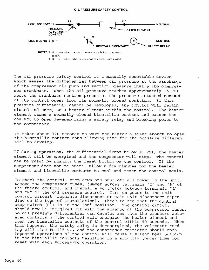
The freeze control is very similar to the oil pressure control inoperation except that it senses evaporator pressure only rather thana pressure differential. It contains a pressure actuated contactthat upon a fall in evaporator pressure energizes a heater elementthat in turn opens a normally closed bimetallic contact. When thebimetallic contact opens, it de-energizes the entire control circuitexcept for the compressor crankcase heaters and cooler heater. Thecontrol is factory set to close at 52 PSIG and open at 54 to 57 PSIG.It takes approximately 60 seconds to warm the heater element enoughto open the bimetallic contact. This time delay period preventsnuisance cutouts due to a momentary drop in suction pressure, butsince the control senses pressure rather than temperature, it stillprovides quicker response for protection than a temperature sensingcontrol.
Page 41

To check the control, the system must be operating. A voltmeter shouldbe connected across terminals of the pressure activated contact. Withthe unit running, there should be a 115 volt potential across theseterminals. Observing evaporator pressure, move the pumpdown switch(es)(PSl and PS2) to the "manual pumpdown" position. Evaporator pressurewill begin to drop. When the voltmeter goes to zero, the pressure acti-vated contacts of the control will have closed. Note the evaporatorpressure at which this happens. Because the unit will have pumpeddown before the 60 second delay period, bimetallic contacts L & M willnot open before the unit shuts down. This part of the control opera-tion may be checked after the pumpdown cycle is complete by connectinga jumper from terminal 1 in the control center to terminal T2 of thecontrol. This will energize the heater element of the control providedthat evaporator pressure is sufficiently low. Within about 60 seconds,the bimetallic contacts of the control should open.
Should the control(s) cause the unit to shut down during normal op-eration, a period of about 2 minutes will be required before thebimetallic contacts of the control will have cooled enough to allowthe control to be manually reset. Similar to the oil pressure safe-ty control, repeated successive operations of the freeze control willprolong the time required before reset.
Fantrol - Head Pressure Control
Fantrol is a system for progressively turning on or off condenserfans when they are no longer required. This is done to reduce con-denser capacity (typically in low outdoor ambient temperatures) andis accomplished by a combination of pressure and temperature actu-ated controls. The first fan (No. 11) is started by its contactorwhen the first compressor in the unit starts. The second fan (No.12) is controlled by a pair of parallel wired pressure switches,one of which senses condenser pressure in refrigerant circuit No.1and one which senses pressure in circuit No.2. The third fan (No.13-3 fan units only) is controlled by a pair of parallel wired tem-perature switches, one of which senses condenser air inlet tempera-ture for refrigerant circuit No.1 and one for circuit No.2. Pressureand temperature control set points are indicated below.
-1* No. fan 13 on 060 and 065 unit.
To check the cut-in points of the controls, the unit must initiallybe off. With the unit prepared for start up according to the pro-cedures outlined in this bulletin, move pumpdown switches (PSl & PS2)to the "auto. pumpdown" position. Evaporator pressure will begin torise and the compressor(s) should start with fan No. 11 startingimmediately. After the compressor(s) starts, observe condenserpressure as it rises. When the condenser pressure reaches approxi-mately 270 PSIG, contactor Ml2 should pull in to start fan No. 12.On 3 fan units, fan No. 13 should start via contactor Ml3 wheneverthe ambient air at the condenser inlet reaches 80F.
Page 42

It may be difficult to check the cut-out point of fan No. 13 (on 3fan units) at the instant it happens, but it should be off wheneverthe ambient air at the condenser inlet is below 70F. To check thecut-out point of fan No. 12, some means of reducing the load on theunit must be available or the fan operation and condenser pressure(s)must be observed as the load drops off naturally. When the conden-ser pressure drops to approximately 170 PSIG, contactor Ml2 shoulddrop out to turn off fan No. 12.
Dampertrol - Optional Head Pressure Control
t t0 0 0 - DAMPER SEC T I O N
DAMPERTROL IN OPEN POSITION
UNIT CONDENSER
r DAMPER SECTION
CONDENSER
DAMPERTROL IN BYPASS POSITION
Dampertrol is also a system for reducing condenser capacity when itis not required. It consists of an assembly of damper blades, link-ages and blade operators installed over the first fan turned on byFantrol (Fan No. 11) and arranged to operated as shown above. Theblade operators sense condenser pressure and extend or contract inresponse to that pressure to open or close the damper blades as re-quired to maintain adequate condenser pressure. The operators arefactory set to begin opening the damper blades at 170 _+ 5 PSIG andto be fully open at 250 _+ 10 PSIG.
To check the damper blade operator pressure settings, the unit shouldbe started with the fuses removed from fans 11 and 13 (on 3 fan unitsonly). At condenser pressures below 170 2 5 PSIG, the damper bladesshould be completely closed. As pressure rises above 170 2 5 PSIG,the damper blades should begin opening and be fully open at 250 +10 PSIG, leaving the fuses in on fan 12 will prevent head pressurefrom becoming excessive since this fan will start after the fullyopen setting of the damper operators has been observed.
Page 43

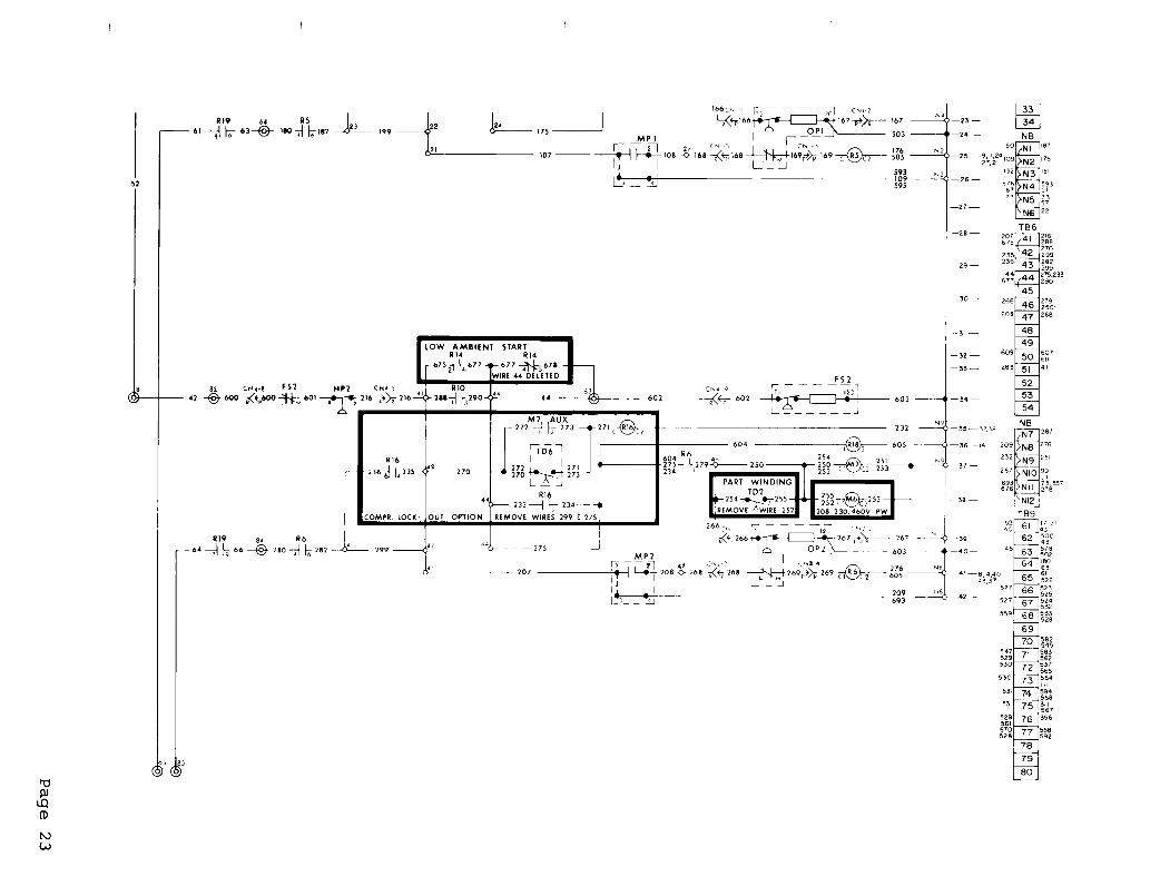
Part Windinq Start - Optional
LINE
PART WINDING COMPRESSOR CONTACTOR
;;;I
(2nd MOTOR WINDING)NOTE: Line IS only hot when the unit thermostat calls for compressor to run
Part winding start is available on all voltage units and consists ofa solid state time delay wired in series with the contactor that ener-gizes the 2nd winding of each compressor motor. Its purpose is tolimit current in-rush to the compressors upon start up. As each com-pressor starts, the contactor for the first motor winding is energizedinstantly while that for the second motor winding is delayed for 1second.
Control checkout is best accomplished by observation as each contac-tor is pulled in to see that the 1 second delay occurs before thesecond contactor pulls in.
Low Ambient Start - Optional
NOTE : Line is only hot when the unit thermostat calls for compressor to run
Low ambient start is available on all units as an option with Fantroland included automatically with optional Dampertrol or Seasontrol.It consists of a solid state normally closed time delay wired inseries with a relay. These are both wired in parallel to the liquidline solenoid valve so that when the solenoid valve is energized bythe unit thermostat, the low ambient start relay is also energizedthrough the time delay. The relay has contacts that essentiallyshort circuit the low pressure control and allow the compressor tostart with the low pressure control open.
After about 2 3/4 minutes, the time delay will open and de-energizethe relay. If the system has not built up enough evaporator pressureto close the low pressure control, the compressor will stop. Thetime delay can be reset to its original normally closed position bymoving the pumpdown switch(es) (PSl or PS2) to the "man. pumpdown"position. Moving the pumpdown switch back to the "auto. pumpdown"position will again energize the relay for another attempt at start
up. If the system has built up enough evaporator pressure, the com-pressor will continue to run.
Page 44

To check the control, turn off all power to the unit and remove thewire(s) (No. 113 SC 213) leading to the low pressure control(s) (LPl& LP2) from terminal 4 in the unit control center. Remove the com-pressor fuses and jumper across terminals L & M of the freeze con-trol(s) and oil pressure safety control(s). Energize the controlcircuit by turning on the control circuit disconnect or main powerdisconnect (depending on the installation) and the control stopswitch Sl. The compressor contactors should pull in instantly.After about 2 3/4 minutes they should drop out again.
Compressor Lockout - Optional
LOW PRESSURE COMPRESSOR
RI5I I
MI AUX. II 13NOTE) I t
I ’ ‘2
COMI? LOCKOUTTIME DELAY
NEUTRALS
TO UNIT THERMOSTAT
NOTE: Hot whenever freeze control and high pressure control permit safe operation
Compressor lockout consists of a solid state time delay wired inseries with the compressor contactor( Its purpose is to preventrapid compressor cycling when cooJ_ing demands are erratic. The cir-cuit illustrated above is for the lead compressor in each refriger-ant circuit. The circuit for the second compressor(s) performs thesame function but is wired differently (see unit wiring diagram).
When the unit thermostat no longer calls for cooling and the com-pressor contactor have opened, the lockout time delay breaks openthe circuit preventing compressor re-start.
The circuit remains open for a period of 5 minutes so that if theunit thermostat should call for cooling before the delay period hasexpired, the compressor will not re-start. After 5 minutes, thetime delay will close its contacts to complete the circuit and beready for start up. The time delay opens its contacts whenever pow-er to terminal 4 is interrupted and resets closed automatically af-ter the time delay period.
To check the control, the compressor(s) must be running initially.Move the pumpdown switch (PSl or PS2) to the "man. pumpdown" posi-tion. Immediately after the compressor(s) have stopped running,move the pumpdown switch back to the "auto. pumpdown" position. Thelead compressor should not re-start for 5 minutes. The second com-pressor in theonds after thehigh enough tothe same way.
refrigerant circuit should start approximately 20 sec-lead compressor, provided that the cooling load isrequire it. Each refrigerant circuit can be checked
Page 45
Alarm Bell - Optional
The 24 volt alarm bell is mounted inside the control center but notwired to the control circuit. It is expected that in most cases,the customer will want to relocate the bell where it will be moreeasily heard in the event of a safety failure. There are leads forconnection of the bell inside a junction box which is located in theunit control center. All that is necessary is that the bell bemounted in a preferred location and wired to the leads in the junc-tion box.
The bell is wired into the control circuit so that it will soundwhenever there is a failure due to low oil pressure, motor overload,an evaporator freeze condition, or excessive condenser pressure.
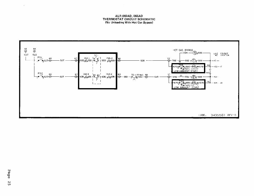
Hot Gas Bypass - Optional
HOT GAS BYPASS PIPING DIAGRAM HOT GAS BYPASS ADJUSTMENT RANGE
R EM OTE BULB ADJUSTMENT RANGE
Solenoid Valve
Remote Bulb
External EqualizerConnection to SuctionSide of Evapoator
Bypass Valve Expansion Valve
30 40 50 60 70 80 90 100 110TEMP (OF) A T B U L B LOCATION
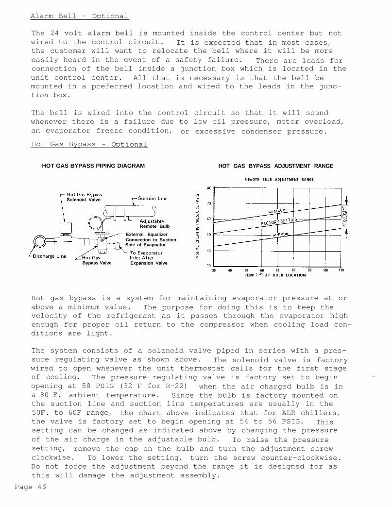
Hot gas bypass is a system for maintaining evaporator pressure at orabove a minimum value. The purpose for doing this is to keep thevelocity of the refrigerant as it passes through the evaporator highenough for proper oil return to the compressor when cooling load con-ditions are light.
The system consists of a solenoid valve piped in series with a pres-sure regulating valve as shown above. The solenoid valve is factorywired to open whenever the unit thermostat calls for the first stageof cooling. The pressure regulating valve is factory set to beginopening at 58 PSIG (32 F for R-22) when the air charged bulb is ina 80 F. ambient temperature. Since the bulb is factory mounted onthe suction line and suction line temperatures are usually in the50F. to 60F range, the chart above indicates that for ALR chillers,the valve is factory set to begin opening at 54 to 56 PSIG. Thissetting can be changed as indicated above by changing the pressureof the air charge in the adjustable bulb. To raise the pressuresetting, remove the cap on the bulb and turn the adjustment screwclockwise. To lower the setting, turn the screw counter-clockwise.Do not force the adjustment beyond the range it is designed for asthis will damage the adjustment assembly.
Page 46

The regulating valve opening point can be determined by slowly re-ducing the system load (or increasing the required chilled water tem-perature setting indicated on the unit thermostat), while observingthe suction pressure. When the bypass valve start to open, the re-frigerant line on the evaporator side of the valve will begin tofeel warm to the touch.
CAUTION: The hot gas line may become hot enough tocause injury in a very short time so careshould be taken during valve checkout_
UNIT MAINTENANCE
General
CAUTION: Disconnect all power before doing
On initial start up and periodically during
any service inside the unit.
operation after install-ation it will be necessary to perform certain routine service checks.Among these are checking the compressor oil level and taking conden-sing, suction, and oil pressure readings. During operation, the oillevel should be visible in the oil sight glass with the compressorrunning. On units ordered with gauges, condensing suction and oilpressures can be read from the unit control center. The gauges arefactory installed with a manual shut off valve on each gauge line.The valves should be closed at all times except when gauge readingsare being taken. On units ordered without gauges, the gauge shutoff valves come factory installed inside the unit control center forconvenient connection of service gauges from outside the unit.
Refriqerant Siqht Glass
The refrigerant sight glasses should be observed periodically. (amonthly observation should be adequate.) A clear glass of liquidindicates that there is adequate refrigerant charge in the unit toinsure proper feed through the expansion valve. Bubbling refriger-ant in the sight glass indicates that the unit is short of refrig-erant charge. An element inside the sight glass is sensitive tomoisture. A color key on the face of the sight glass indicates whatmoisture condition corresponds to a given element color. If thesight glass does not indicate a dry condition after a few hours ofoperation the unit should be pumped down and the cores in the filter-driers changed.
Filter-Driers
To change the filter drier core(s), pump th e unit down by movingpumpdown switches (PSl & PS2) to the "man. pumpdown" position.Turn off all power to the unit and install jumpers from terminals21 to 24 and 41 to 44. Turn power to the unit back on and re-startthe unit by moving pumpdown switches (PSl & PS2) to the "auto. pump-down" position. Close the manual liquid line shutoff valve(s) andwhen evaporator pressure reaches 0 PSIG, move the control stopswitch (Sl) to the "off" position. This will close the liquid linesolenoid valve(s) and isolate the short section of refrigerationpiping containing the filter-drier(s). Remove the cover plate fromthe filter-drier shell and replace the core(s).
After core replacement, replace the cover plate. A leak check a-round the flange of the filter-drier shell is recommended after thecores have been changed.
Page 47

Liquid Line Solenoid Valve
The liquid line solenoid valves, which are responsible for automaticpumpdown during normal unit operation, do not normally require anymaintenance. They may, however, require replacement of the solenoidcoil or of the entire valve assembly.
The solenoid coil may be removed from the valve body without openingthe refrigerant piping by moving pumpdown switches (PSl & PS2) tothe " m a n . pumpdown" position. The coil can then be removed from thevalve body by simply removing a nut or snap ring located at the topof the coil. The coil can then be slipped off its mounting stud forreplacement. Be sure to replace the coil on its mounting stud be-fore returning pumpdown switches (PSl & PS2) to the "auto. pumpdown"position.
__To replace the entire solenoid valve, the unit must be pumped down byuse of the manual liquid line valve.
Thermostatic Expansion Valve
INLET
POWER ELEMENT(CONTAINS DIAPHRAGM)
ADJUSTMENT SCREW
v/ CAP
HYDRAUL .IC FILLBETWEEN DI APHRAMS
The expansion valve is responsible for allowing the proper amount ofrefrigerant to enter the evaporator regardless of cooling load. Itdoes this by maintaining a constant superheat. (Superheat is thedifference between refrigerant temperature as it leaves the evapor-ator and the saturation temperature corresponding to the evaporatorpressure.) All ALR chillers are factory set for between 8F and 12Fsuperheat. If it is necessary to increase the superheat setting ofthe valve, remove the cap at the bottom of the valve to expose theadjustment screw. Turn the screw clockwise (when viewed from theadjustment screw end) to increase the superheat setting and counter-clockwise to reduce superheat. Allow time for system rebalance af-ter each superheat adjustment.
Page 48

The expansion valve, like the solenoid valve, should not normallyrequire replacement, but if it does, the unit must be pumped down byusing the manual liquid line shutoff valve. If the problem can betraced to the power element only, it can be unscrewed from the valvebody without removing the valve but only after pumping the unit downwith th e manual liquid line shutoff valves.
atorrEvapor
TOP VIEW OF TYPICAL DUAL CIRCUITSHELL AND TUBE EVAPORATOR
TER BAFFLES
ATER NOZZELS
TUBE SHEETSHEAD RINGS
LIQUID CONNECTIONS
SUCTlOhl CONNECTION
The evaporator is of the direct expansion, shell and tube type withrefrigerant flowing through the tubes and water flowing through theshell over the tubes. The tubes are internally finned to provide ex-tended surface as well as turbulent flow of refrigerant through thetubes. Normally no service work is required on the evaporator.There may be instances where a tube will leak refrigerant into thewater side of the system. In the cases where only one or two tubesleak. the problem can best be solved by plugging the tube at bothends. When the tube must be replaced, the old tube can be removedand replaced.
To remove a tube, the unit should be temporarily pumped down by mov-ing pumpdown switches (PSl & PS2) to the "man. pumpdown" position.Power to the unit should be shut off to install jumpers from termi-nals 21 to 24 and 41 to 44. Turn power to the unit back on the pumpdown both refrigerant circuits until evaporator pressure is at ornear 0 PSIG by closing the manual liquid line shutoff valves at theoutlet of each condenser. Close both compressor suction valves byturning the valve stems clockwise. These steps will insure a mini-mum amount of refrigerant loss when the evaporator is opened up.The tubes are mechanically expanded into the tube sheets (see sketchabove) at each end of the cooler. In order to remove the tubes itis necessary to break this bond by collapsing the tube. After doingthis at both ends of the shell, the tube can be removed for replace-ment. The new tube can then be inserted and re-expanded into thetube sheet.
Page 49
NOTE: The bond produced by expansion must be refri-gerant tight. This bond must be produced byrolling the tube into the tube sheet.
After re-assembling the evaporator, a small amount of refrigerantshould be introduced by momentarily opening the manual liquid linevalve. A leak check should then be performed on the evaporator.
Tube removal can only take place after the leaking tube is located.This aspect depends on the ingenuity of the serviceman. One methodthat would work would be to subject each tube to air pressure byplugging each end, and with a pressure gauge attached to one of theend plugs observe to see if there is a loss of air pressure over aperiod of a minute or two.
Note: The evaporator should always be supplied withclean water to minimize scale build up on therefrigerant tubes.
Condensers
Condensers are air cooled and constructed with 3/8 O.D. copper tubesbonded in a staggered pattern into rippled aluminum fins. No main-tenance is ordinarily required except the occasional removal of dirtand debris from the outside surface of the fins. Care should be takennot to damage the fins during cleaning.
Compressor Wear and Lead-Lag
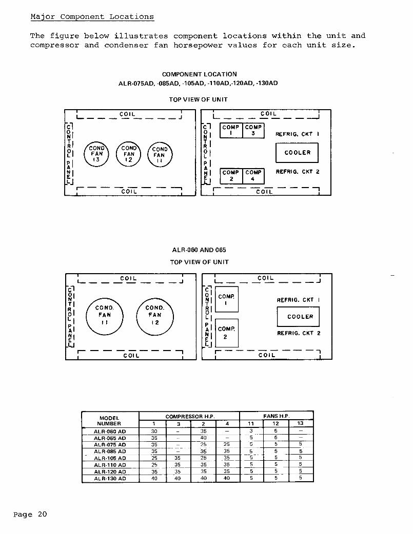
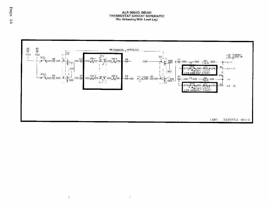
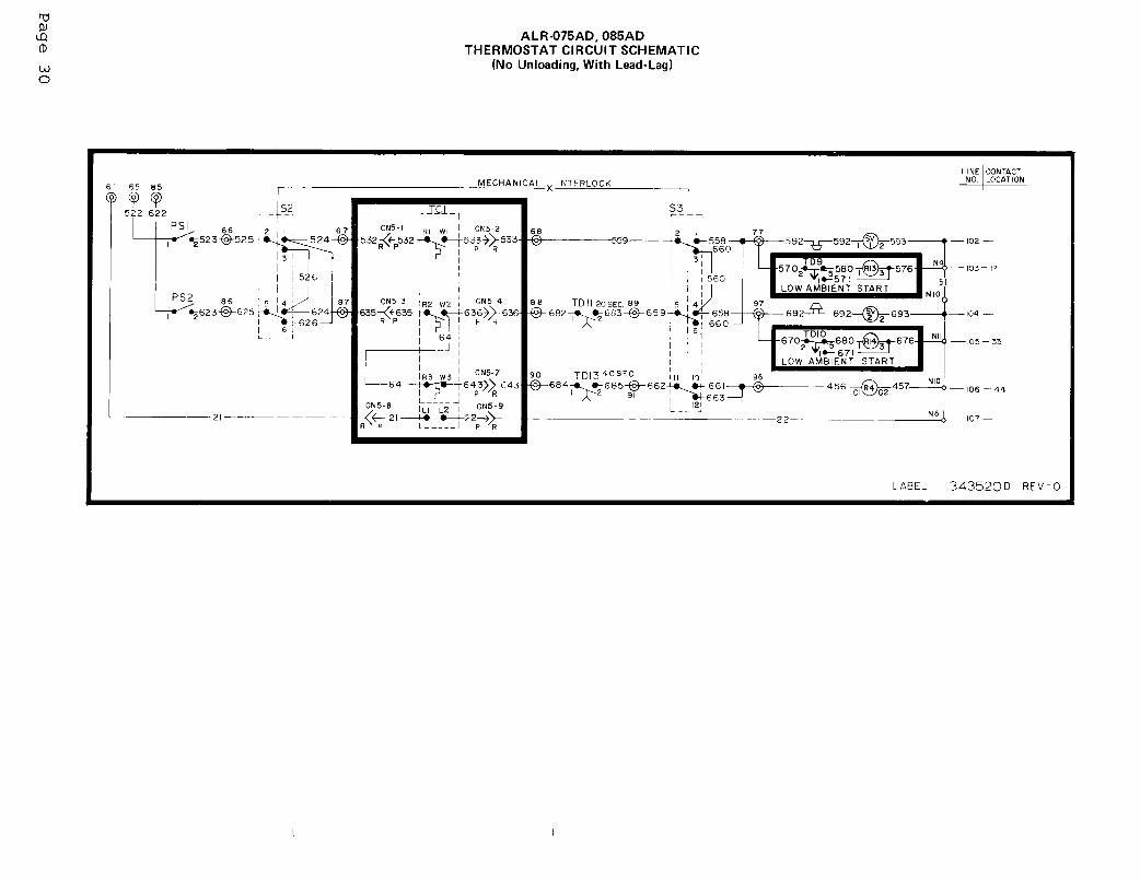
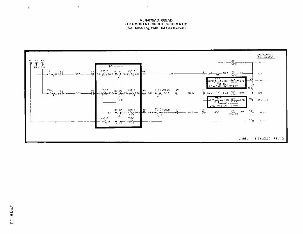
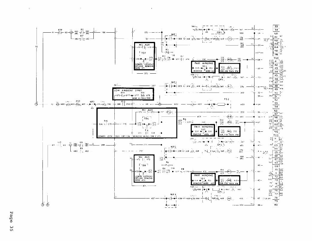
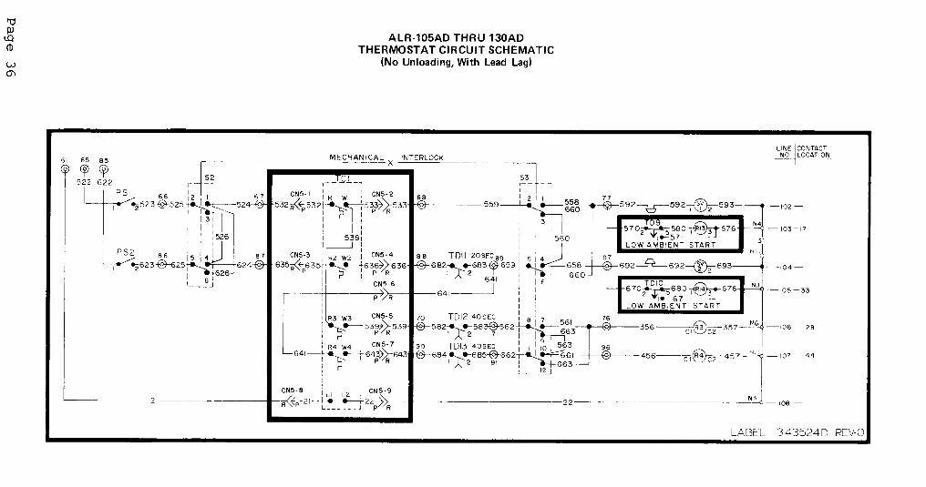
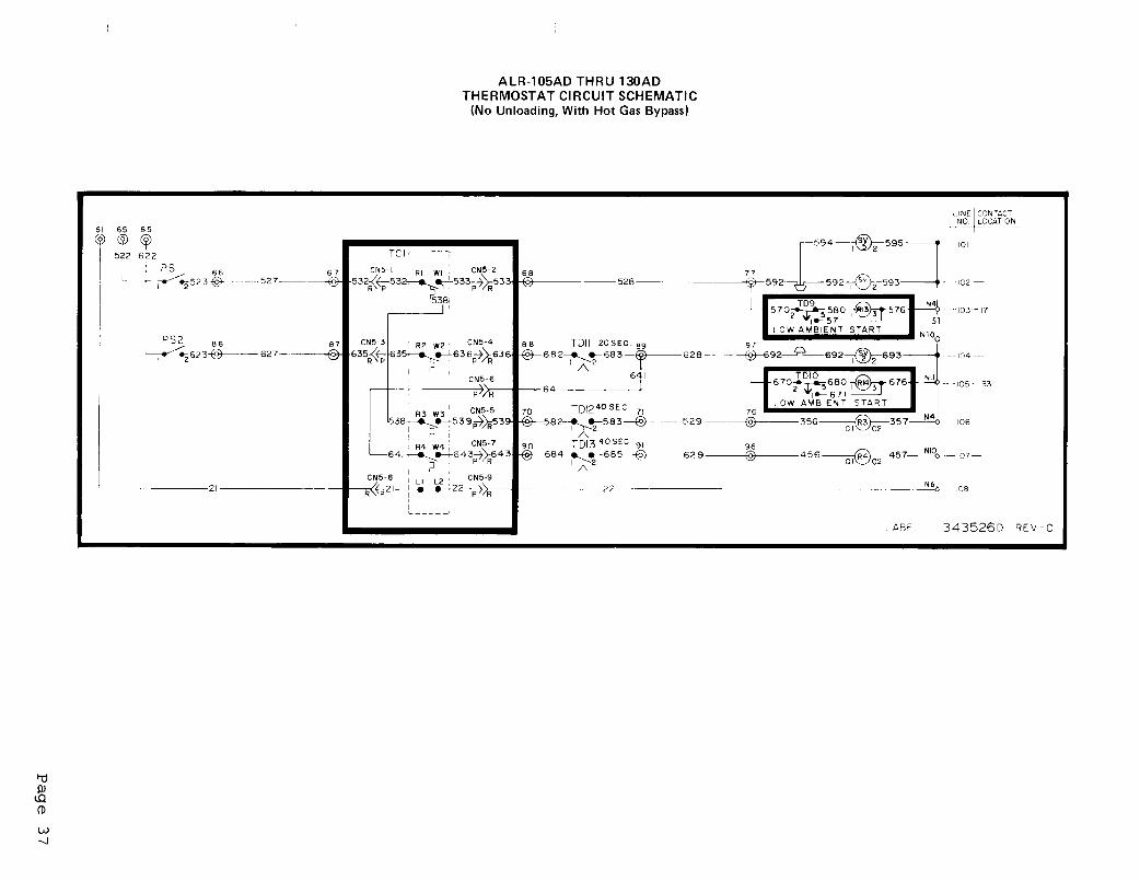
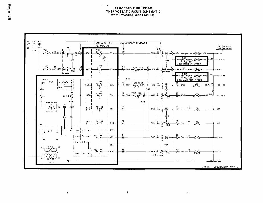
A standard feature on all McQuay ALR air cooled chillers is a systemfor reversing the sequence that compressors start in. (Chillers withthe hot gas bypass option do not have lead-lag.) For example, on a 4compressor unit with the lead-lag switches in the "circuit 1 leads"position, the normal starting sequence is 1, 2, 3, 4. With the lead-lag switches in the "circuit 2 leads" position, the reversed startingsequence is 2, 1, 4, 3 (see Component Location Diagram on Page 20).It is achieved electrically bu a multi-pole switching arrangement (seeControl Schematics on Pages 22 through 45. It is suggested that thelead lag switches in the unit control center be switched annually toprovide long compressor life.
Compressor Oil Level
Because of the large refrigerant charge required in an air cooled con-densing unit it is usually necessary to put additional oil into thesystem. The oil level should be watched carefully upon initial startup and for sometime thereafter.
At the present time, Suniso #3GS oil is the only oil approved by Cope-land for use in these compressors. The oil level should be maintainedat about the midpoint of the sight glass on the compressor body.
Fan Belt Tension
Check the belt tension after the first 48 hours of operation. By thistime the belts should have acquired their permanent stretch and fur-ther adjustments should not be necessary. However it is advisable torecheck the belt tension every 3 months.
Fan Shaft Bearings-The fan shaft bearings do not require lubrication at the time the unitis put into service. The fan shaft bearings should be greased once ayear using STANDARD OIL COMPANY AMCO Multi-Purpose Lithium Grease.DO NOT OVERLUBRICATE.
Page 50

Fan Motor Bearings
All fan motors are ball bearing, pre-lubricated and do not require theaddition of grease at the time of installation. \Periodically, the ball ;bearings should be cleaned and the grease renewed, to gain the ulti- 1,mate in service from the motor bearings. i
Extreme care must be exercised to prevent foreign matter from entering /the ball bearings. It is also important to avoid overgreasing. Only / (1a high grade clean mineral grease having the following characteristicsshould be used. Consistency: A little stiffer than that of Vaseline, /maintained over the operating temperature range; melting point prefer-.,'
,
ably over 150C (302OF); freedom from separation of oil and soap under /operating and storage conditions and freedom from abrasive matter,acid, alkali and moisture.
Specific greasing instructions are to be found on the label attachedto the unit and should be generally followed.
Electrical Terminals
CAUTION! ELECTRIC SHOCK HAZARD, TURN OFF ALL POWER BEFOREWITH FOLLOWING SERVICE.
All power electrical terminals should be retightened everyas they tendthe wire.
COMPRESSOR:who maintain
CONTINUING
6 months,to loosen in service due to normal heating and cooling at
IN WARRANTY RETURN MATERIAL PROCEDURE
Copeland Refrigeration Corporation has stocking wholesalersa stock of replacement compressors and service parts to
serve refrigeration contractors and servicemen as required.
When a compressor fails in warranty, the inoperative compressor can betaken to any authorized Copeland Wholesaler for an over-the-counter ex-change or an advance replacement can be obtained. Credit is issued onthe returned compressor upon receipt and factory inspection of the in-operative compressor. In this transaction, be certain that the com-pressor is definitely defective. If a compressor is received from thefield that tests satisfactorily, a service charge plus a transportationcharge will be charged against its original credit value.
On all out-of-warranty compressor failures, Copeland offers the samefield facilities for service and/or replacement as described above.The credit issued on the returned compressor will be determined by therepair charge established for that particular unit.
COMPONENTS OTHER THAN COMPRESSORS - Material may not be returned ex-cept by permission of authorized factory service personnel of McQuay,Inc. at Mpls., Minn. A "Return Goods" tag will be sent to be includedwith the returned material. Enter the information as called for on thetag in order to expedite handling at our factories and prompt issuanceof credits.
The return of the part does not constitute an order for replacement.Therefore, a purchase order must be enetered through your nearestMcQUAY Representative. The order should include part name, part number,model number and serial number of the unit involved.
Following our personal inspection of the returned part, and if it isdetermined that the failure is due to faulty material or workmanship,credit will be issued on customer's purchase order.
All parts shall be returned to the pre-designated McQUAY factory, trans-portation charges prepaid.
Page 51

TROUBLE SHOOTING CHART
PROBLEM
Compressorwill not run.
Compressor noisyor vibrating.
High DischargePressure
Low DischargePressure.
High SuctionPressure
Low SuctionPressure
Compressor wi ll lnot unloador load up.
CompressorLoading - UnloadingIntervals too short
Little or nooil pressure.
Compressorloses oil.
Motor overloadrelays open orfuses blown.
Compressor thermalProtector Switchopen.
Freeze protectionopens.
POSSIBLE CAUSES
1. Main switch open.2. Fuse blown.
3. Thermal overloads tripped or fuses blown.
4. Defective contactor or coil.5. System shut down by safety devices.
6. No cooling required.7. Liquid line solenoid will not open.8. Motor electrical trouble.9. Loose wiring1. Flooding of refrigerant into crankcase.2. Worn compressor.1. Dirty tube and fin surface (air cooled
condenser).2. Non-condensibles in system.3. System overcharged with refrigerant.4. Discharge shut off valve partially closed.1. Faulty condenser temperature regulation.2. Suction shutoff valve partially closed.3. Insufficient refrigerant in system.4. Low suction pressure.5. Compressor operating unloaded.
6. Low ambient controls not set properly.1. Excessive load.2. Expansion valve overfeeding.3. Compressor unloaders open.
1. Lack of refrigerant.2. Evaporator dirty.3. Clogged liquid line filter-drier.4. Clogged suction line or compressor suction
gas strainers.5. Expansion valve malfunctioning.6. Condensing temperature too low.7. Compressor will not unload.8. Insufficient water flow.1. Defective capacity control.2. Unloader mechanism defective.3. Faulty thermostat stage or broken capillary
tube.4. Stages not set for application.
1. Erratic water thermostat.2. Insufficient water flow.
1. Clogged suction oil strainer.2. Excessive liquid in crankcase.
3. Oil pressure gauge defective.
4. Low oil pressure safety switch defective.5. Worn oil pump.6. Oil pump reversing gear stuck in wrong
position.7. Worn bearings.8. Low oil level.9. Loose fitting on oil lines.
10. Pump housing gasket leaks.11. Flooding of refrigerant into crankcase.
1. Lack of refriaerant.2. Excessive compression ring blow-by.1. Low voltage during high load conditions.2. Defective or grounded wiring in motor or
power circuits.3. Loose power wiring.4. High condensing temperature.5. Power line fault causing unbalanced voltage.
6. High ambient temperature around theoverload relay.
7. Failure of second starter to pull in on part-winding start systems.
1. Operating beyond design conditions.2. Discharge valve partially shut.3. Blown valve plate gasket.1. Thermostat set too low.2. Low water flow.3. Low suction pressure.
POSSIBLE CORRECTIVE STEPS
1. Close switch.2. Check electrical circuits and motor winding for shorts or
grounds. Investigate for possible overloading. Replacefuse after fault is corrected.
3. Overloads are auto. reset. Check unit closely when unitcomes back on line.
4. Repair or replace.5. Determine type and cause of shutdown and correct it.
before resetting safety switch.6. None. Wait until unit calls for cooling.7. Repair or replace coil.8. Check motor for opens, short circuit or burn-out.9. Check all wire junctions. Tighten all terminal screws.1. Check setting of expansion valve.2. Replace.1. Clean.
2. Purge the non-condensibles.3. Remove excess.4. Open valve.1. Check condenser control operation.2. Open valve.3. Check for leaks. Repair and add charge.4. See below for Corrective Steps for low suction pressure.5. See below for Corrective Steps for failure of compressor
to load up.6. Reset controls.1. Reduce load or add additional equipment.2. Check remote bulb. Regulate superheat.3. See Corrective Steps below for failure of compressor
to load up.1. Check for leaks. Repair and add charge.2. Clean chemically.3. Replace cartrrdgefs).4. Clean strainers.
5. Check and reset for proper superheat. Replace if necessary.6. Check means for regulating condensing temperature.7. See Corrective Steps for failure of compressor to unload.8. Adjust gpm.1. Replace.2. Replace.3. Replace
4. Reset thermostat setting to fit application.
1. Replace.2. Adjust gpm.
1. Clean.2. Check crankcase heater. Reset expansion valve for higher
superheat. Check liquid line solenoid valve operation.3. Repair or replace. Keep valve closed except when taking
readings.4. Replace.5. Replace.6. Reverse direction of compressor rotation.
7. Replace compressor.8. Add oil.9. Check and tighten system.
10. Replace gasket.11. Adjust thermal expansion valve.
1. Check for leaks and repair. Add refriaerant.2. Replace compressor.1. Check supply voltage for excessive line drop.2. Replace compressor-motor.
3. Check all connections and tighten.4. See Corrective Steps for high discharge pressure.5. Check supply voltage. Notify power company. Do not
start until fault is corrected.6. Provide ventilation to reduce heat.
7. Repair or replace starter or time delay mechanism.
1. Add facilities so that conditions are within allowable limits2. Open valve.3. Replace gasket.1. Reset to 400F or above.2. Adjust gpm.3. See “Low suction pressure”.
FORM 339274Y REV. A