p.a.c.e. academy for gifted...
TRANSCRIPT

PROJECT MANUAL
BIDDING REQUIREMENTS, CONTRACTING REQUIREMENTS and
ARCHITECTURAL SPECIFICATIONS
P.A.C.E. ACADEMY FOR GIFTED STUDENTS
PHASE 1 INTERIOR RENOVATIONS 12 Bond Street, Richmond Hill, Ontario
File No. 18054 May 30, 2019

P.A.C.E. Academy for Gifted Students Phase 1 Interior Renovations 00 01 01 MCA File No. 18054 Project Title Page
00 01 01 - 1
May 30, 2019
PROJECT NAME PACE ACADEMY CLASSROOM RENOVATIONS
OWNER P.A.C.E. Academy of Gifted Children 12 Bond Crescent Richmond Hill, Ontario, L4E 3K2 Tel: 905-773-0997 Attn: Mr. Matthew Ross E-mail: [email protected]
CONSULTANT MC Architects Inc. 1881 Yonge Street, Suite 400 Toronto, Ontario M4S 3C4 Tel: 416-489-4646 Fax: 416-489-6989 Attn: Ms. Jill Tonini E-mail: [email protected]
STRUCTURAL Engineering Link Incorporated SUB-CONSULTANT 207 Adelaide Street East, Suite 200 Toronto, Ontario M5A 1M8
Tel: 416-599-5465 x 118 Fax: 416-471-6083 Attn: Mr. Randall DeLong, P.Eng. E-mail: [email protected]
MECHANICAL DEI & Associates Inc. SUB-CONSULTANT 55 Northland Road
Waterloo, Ontario N2V 1Y8 Tel: 519-725-3555 Fax: 519-725-2515 Attn: Mr. Michael Demaiter E-mail: [email protected]
ELECTRICAL DEI & Associates Inc. SUB-CONSULTANT 55 Northland Road
Waterloo, Ontario N2V 1Y8 Tel: 519-725-3555 Fax: 519-725-2515 Attn: Mr. Aaron Jones E-mail: [email protected]
END OF DOCUMENT

P.A.C.E. Academy for Gifted Students Phase 1 Interior Renovations 00 01 07 MCA File No. 18054 Seals Page
00 01 07 - 1
May 30, 2019
CONSULTANT=S SEAL This seal governs: DIVISION 1 to 12, of the specifications
END OF DOCUMENT

P.A.C.E. Academy for Gifted Students Phase 1 Interior Renovations 00 01 10 MCA File No. 18054 Table of Contents Document No. Title No. of Pages
00 01 10 - 1
May 30, 2019
VOLUME I BIDDING REQUIREMENTS CONTRACTING REQUIREMENTS and
ARCHITECTURAL and STRUCTURAL SPECIFICATIONS
INTRODUCTORY INFORMATION
00 01 01 Project Title Page .............................................................................................................................. 1 00 01 07 Seals Page.......................................................................................................................................... 1 00 01 10 Table of Contents .............................................................................................................................. 2 00 01 80 List of Abbreviations ......................................................................................................................... 4
BIDDING REQUIREMENTS
00 21 00 Instructions to Bidders ...................................................................................................................... 7 00 31 00 Available Project Information ........................................................................................................... 1
Designated Substances Survey Report ............................................................................................ 47 00 41 00 Bid Form ............................................................................................................................................ 6 00 43 00 Supplementary Bid Form .................................................................................................................. 6
CONTRACTING REQUIREMENTS
00 52 00 Agreement Form and Definitions ...................................................................................................... 2 00 72 00 General Conditions ........................................................................................................................... 1 00 73 00 Supplementary Conditions ................................................................................................................ 8
DIVISION 1 - GENERAL REQUIREMENTS
01 00 00 General Requirements .................................................................................................................. 10
DIVISION 2 – EXISTING CONDITIONS
02 41 19 Selective Demolition ......................................................................................................................... 3
DIVISION 3 - CONCRETE
03 30 00 Cast-in-Place Concrete (MCA) ........................................................................................................... 2 03 35 00 Concrete Floor Finishing ................................................................................................................... 3
DIVISION 4 - MASONRY
04 20 00 Masonry .......................................................................................................................................... 7 DIVISION 5 – METALS 05 52 00 Metal Railings for Stairs .................................................................................................................... 2
DIVISION 6 – WOOD, PLASTICS, AND COMPOSITES
06 10 00 Rough Carpentry ............................................................................................................................... 2 06 20 00 Finish Carpentry ................................................................................................................................ x

00 01 10 P.A.C.E. Academy for Gifted Students Phase 1 Interior Renovations Table of Contents MCA File No. 18054 Document No. Title No. of Pages
00 01 10 - 2 May 30, 2019
06 41 05 Plastic Laminates ............................................................................................................................... 2 06 41 10 Architectural Woodwork ................................................................................................................... 5 06 41 93 Cabinet and Miscellaneous Hardware .............................................................................................. 3
DIVISION 7 - THERMAL AND MOISTURE PROTECTION
07 21 13 Board Insulation ................................................................................................................................ 2 07 27 00 Air Barriers ........................................................................................................................................ 3 07 84 00 Fire Stopping and Smoke Seals ......................................................................................................... 3 07 92 00 Sealants ............................................................................................................................................. 4
DIVISION 8 - OPENINGS
08 11 00 Steel Doors and Frames .................................................................................................................... 5 08 71 00 Door Hardware.................................................................................................................................. 4 08 80 00 Glazing ............................................................................................................................................... 4
DIVISION 9 - FINISHES
09 22 16 Non-Structural Metal Framing .......................................................................................................... 2 09 29 00 Gypsum Board ................................................................................................................................... 4 09 30 13 Ceramic Tile ....................................................................................................................................... 6 09 51 00 Acoustical Ceilings ............................................................................................................................. 5 09 65 19 Resilient Tile Flooring ........................................................................................................................ 4 09 91 00 Painting ............................................................................................................................................. 8
DIVISION 10 - SPECIALTIES
10 11 15 Markerboards ................................................................................................................................... 3 10 11 20 Tackboards ........................................................................................................................................ 2 10 21 15 Plastic Toilet Partitions ...................................................................................................................... 3 10 28 13 Washroom Accessories ..................................................................................................................... 4 DIVISION 11 – EQUIPMENT Not Used DIVISION 12 – FURNISHINGS 12 24 13 Window Shades................................................................................................................................. 2 DIVISION 12 – to DIVISION 41 Not Used
END OF DOCUMENT

P.A.C.E Academy for Gifted Students Phase 1 Interior Renovations 00 01 60 MCA File No. 18054 List of Invited Bidders
00 01 60 - 1
May 30, 2019
1. GENERAL .1 This is an invited Tender. General Contract bidders submitting a bid require acceptance by the Owner
prior to obtaining Bid Documents. Refer to article 2 below.
2. GENERAL CONTRACT BIDDERS
The following General Contract bidders have been invited to bid:
.1 Balmain Construction Ltd 68 Millwick Drive Toronto, Ontario, Phone No.: 416-742-3950 Email: [email protected] Contact: Andrew DiLorenzo
.2 Paulsan Construction Inc 408 Henry Street, Unity 1 Brantford, Ontario, N3S 7W1 Phone No.: 519-304-7555
.3 Deciantis Construction Limited 2-475 Edward Avenue Richmond Hill, Ontario, L4C 5E5 Phone No.: 905-884-5131 Fax No.: 905-883-5243 Email: [email protected] Contact: Mr. R.D. Deciantis
.4 Gen-Pro/1320376 Ontario Ltd 2211 Plains Road East Burlington, Ontario, L7R 3R3 Phone No.: 905-333-5217 Fax No.: 905-333-5746 Email: [email protected] Contact: Mr. John Dawson
.5 Gerr Construction Ltd. 325 Lake Road Bowmanville, Ontario, L1C 4P8 Phone No.: 905-697-2290 Fax No.: 905-697-2723 E-mail: [email protected] Contact: Mr. Neil Gerrits
.6 J.J. McGuire General Contractors Inc. 1-880 Farewell Street Oshawa, Ontario, L1H 6N6 Phone No.: 905-436-2554 Fax No.: 905-436-8692 Email: [email protected] Contact: Mr. Jeff Robinson

00 01 60 P.A.C.E Academy for Gifted Students Phase 1 Interior Renovations List of Invited Bidders MCA File No. 18054
00 01 60 - 2 May 30, 2019
.7 Morosons Construction Ltd. 103 Fairbank Avenue Toronto, Ontario, M6E 3Y9 Phone No.: 416-233-4171 Fax No.: 416-781-7370 Contact: Mr. Haitham Radwan Email: [email protected] [email protected]
.8 Rutherford Contracting Ltd 224 Earl Stewart Drive Aurora, Ontario, L4G 6V7 Phone No.: 905-726-4888 Fax No.: 905-726-4889 Email: [email protected] Contact: Mr. Blair Chalmers
.9 Silver Birch Contracting Ltd 17045 Highway 27 Schomberg, Ontario, L0G 1T0 Phone No.: 905-952-3856 Fax No.: 905-952-3857 Email: [email protected] Contact: Mr. Dan Steenhoek
.10 Harrington and Associates 9821 Leslie Street, Suite 105 Richmond Hill, Ontario L4B 3Y4 Phone No.: 905-737-8185 Fax No.: 905-737-8180 E-mail: [email protected] Contact: Michele Del Duca .11 Remo General Contracting Ltd 2400 North Park Drive Brampton, Ontario, L6S 5M5 Phone No.: 905-792-0700 Fax No.: 905-792-7583 E-mail: [email protected] Contact: Mr. Raymondo Mollica
END OF DOCUMENT

P.A.C.E. Academy for Gifted Students Phase 1 Interior Renovations 00 01 80 MCA File No. 18054 List of Abbreviations
00 01 80 - 1
May 30, 2019
A
& AND @ AT ACT ACOUSTICAL TILE ADJ ADJUSTABLE AFF ABOVE FINISHED FLOOR ALT ALTERNATE ALU ALUMINUM ANOD ANODIZED AP ACOUSTICAL PANEL APPROX APPROXIMATE A/V AUDIO VISUAL AUTO AUTOMATIC
B
BBS BASKETBALL BACKSTOP BD BOARD BF BARRIER-FREE BITUM BITUMINOUS BLDG BUILDING BLKG BLOCKING BM BEAM BOT BOTTOM BRK BRICK BUR BUILT-UP ROOFING
C
CA COMMUNICATIONS ASSEMBLY CAB CABINET CAR CARPET C/B CATCH BASIN CB CHALKBOARD CBD CEMENT BOARD C/C CENTRE TO CENTRE CEP COMPOSITE EXTERIOR PANELS CJ CONTROL JOINT CL CENTRE LINE CLG CEILING CMT CERAMIC MOSAIC FLOOR TILE CMU CONCRETE MASONRY UNIT COL COLUMN CONC CONCRETE CONT CONTINUOUS CP CONTROL PANEL C/W COMPLETE WITH CWF CUSHIONED WOOD FLOORING CWT CERAMIC WALL TILE
D
D DEEP (DEPTH) DAMP DAMPPROOFING DET DETAIL DF DRINKING FOUNTAIN DFJ DRINKING FOUNTAIN-JUNIOR ELEM DFK DRINKING FOUNTAIN-KINDERGARTEN DIA DIAMETER DIAG DIAGONAL DIM DIMENSION DN DOWN DW DISHWASHER DWG DRAWING
E
EL ELECTRIC(AL) ELEV ELEVATION EP ELECTRICAL PANEL EPF EPOXY FLOORING EQ EQUAL EQ.T EQUIVALENT THICKNESS EXP EXPANSION EXIST EXISTING EXS EXPOSED STRUCTURE
F
FAWP FABRIC WRAPPED ACOUSTIC WALL PANELS
FD FLOOR DRAIN FE FIRE EXTINGUISHER FEC FIRE EXTINGUISHER CABINET FFL FINISHED FLOOR FFS FLOATING FROST SLAB FH FIRE HYDRANT FHC FIRE HOSE CABINET FIN FINISH(ED) FLEX FLEXIBLE FLR FLOOR FPC FLUOROPOLYMER COATING FPR FIRE PROTECTION RATING FR FIRE RETARDANT FRG FIRE-RATED GLASS FRR FIRE RESISTANCE RATING FS FIRE SEPARATION FSG FLOOR SOCKET-GYMNASTIC TYPE FSP FLOOR SOCKET-POST TYPE FTG FOOTING

00 01 80 P.A.C.E. Academy for Gifted Students Phase 1 Interior Renovations List of Abbreviations MCA File No. 18054
00 01 80 - 2 May 30, 2019
G
GALV GALVANIZE GB GRAB BAR GBA GYPSUM BOARD-ABUSE RESISTANT GBD GYPSUM BOARD GBF GYPSUM BOARD-FIBERGLASS-FACED GBI GYPSUM BOARD-IMPACT RESISTANT GBR GYPSUM BOARD-FIRE RESISTANT GBS GYPSUM BOARD-STANDARD GBW GYPSUM BOARD-WATER RESISTANT GL GLASS (GLAZING) GRND GROUND GYP GYPSUM
H
h HOUR H HIGH (HEIGHT) HB HOSE BIBB HBGC HIGH BUILD GLAZED COATING HCW HOLLOW CORE WOOD HD HAND DRYER HM HOLLOW METAL HORIZ HORIZONTAL HP HIGH POINT HU HEATING UNIT HVAC HEATING, VENTILATING, AND AIR
CONDITIONING HWT HOT WATER TANK
I
ID INSIDE DIAMETER IGU INSULATING GLASS UNIT IMP INSULATED METAL PANEL INSUL INSULATION
J
JCT JUNCTION JT JOINT
L
L LONG (LENGTH) LAB LABORATORY LAM LAMINATE / D / ION LAV LAVATORY LCT LINOLEUM COMPOSITION TILE LGL LAMINATED GLASS LLH LONG LEG HORIZONTAL
LLV LONG LEG VERTICAL LP LOW POINT LS LIGHT STANDARD LSF LINOLEUM SHEET FLOORING LWC LIGHTWEIGHT CONCRETE LWD LINEAR WOOD CEILING
M
MAX MAXIMUM MB MARKER BOARD MECH MECHANICAL MH MANHOLE MHU MECHANICAL HEATING UNIT MIN MINIMUM MIR MIRROR MISC MISCELLANEOUS MO MASONRY OPENING MP METAL PANEL MTD MOUNTED
N
NBCC NATIONAL BUILDING CODE OF CANADA N/A NOT APPLICABLE NFHB NON FREEZE HOSE BIBB NIC NOT IN CONTRACT No. NUMBER NOM NOMINAL NRFS NON-RATED FIRE SEPARATION NTS NOT TO SCALE NWC NORMAL WEIGHT CONCRETE
O
OBC ONTARIO BUILDING CODE O/C ON CENTRE OD OUTSIDE DIAMETER O/H OVERHEAD OWSJ OPEN WEB STEEL JOIST
P
PA PUBLIC ADDRESS SYSTEM PAP PREFINISHED ALUMINUM PANELS PCP PRECAST CONCRETE PAVER PDO POWER DOOR OPERATOR PERIM PERIMETER PERP PERPENDICULAR PL PLATE PLAM PLASTIC LAMINATE PLWD PLYWOOD

P.A.C.E. Academy for Gifted Students Phase 1 Interior Renovations 00 01 80 MCA File No. 18054 List of Abbreviations
00 01 80 - 3
May 30, 2019
POR PORCELAIN FLOOR TILE PMP PREFINISHED METAL PANEL PT PAINT P/C PRECAST PREFAB PREFABRICATED PRE PREFINISHED PTD PAPER TOWEL DISPENSER PUF POLYURETHANE FLOORING
Q
QT QUARRY TILE
R
R RADIUS RA RETURN AIR RACP RIGID ACOUSTICAL CEILING PANEL RAD RADIATOR RAWP RIGID ACOUSTICAL WALL PANEL RB RESILIENT (RUBBER) BASE RD ROOF DRAIN REF REFERENCE REFR REFRIGERATOR REINF REINFORCE / D / ING / MENT REQ REQUIRED REV REVERSE RFL RUBBER TILE FLOORING RFT RESILIENT FLOOR TILE RM ROOM RSF RUBBER SHEET FLOORING RST RUBBER STAIR TREAD RTT RESILIENT TERRAZZO TILE RSI THERMAL RESISTANCE (m2
C/W) RWL RAIN WATER LEADER
S
SAN SANITARY SB MMA SUPPLEMENTARY STANDARDS TO
DIVISION B OF THE OBC SBO SUPPLIED BY OWNER SCW SOLID CORE WOOD SCHED SCHEDULE SD SOAP DISPENSER SF SAFETY FLOORING SFS STRUCTURAL FROST SLAB SGL SPANDREL GLASS SIM SIMILAR SLC SEALED CONCRETE SLF SHEET LINOLEUM FLOORING SNB SANITARY NAPKIN DISPOSAL BIN
SND SANITARY NAPKIN DISPENSER SO SUPPLY ONLY SP SPANDREL PANEL SPEC SPECIFICATIONS SPK SPEAKER SSF SYNTHETIC SHEET FLOORING SS SERVICE SINK SST STAINLESS STEEL STV STAIN AND VARNISH STD STANDARD STL STEEL STRUCT STRUCTURE / STRUCTURAL SUPPL SUPPLEMENT(ARY) SUSP SUSPEND(ED) SVF SHEET VINYL FLOORING S/W SIDEWALK SWC SPECIAL WALL COATING SYM SYMBOL SYMM SYMMETRICAL
T
T THICK TAPS TACTILE ATTENTION PATTERN SURFACE TB TACKBOARD T&B TOP AND BOTTOM TD TOWEL DISPENSER TEL TELEPHONE TEMP TEMPORARY TER TERAZZO TERM TERMINAL TEX TEXTURED TGL TEMPERED GLASS T&G TONGUE AND GROOVE T/O TOP OF TPD TOILET PAPER DISPENSER TR TRANSOM TRD TREAD TRGL TRANSLUCENT GLASS TYP TYPICAL
U
U URINAL UBF URINAL - BARRIER-FREE UC UNDERCUT UJ URINAL - JUNIOR ELEMENTARY UL UNDERWRITERS’ LABORATORIES ULC UNDERWRITERS= LABORATORIES OF
CANADA U/N UNLESS NOTED OTHERWISE UNFIN UNFINISHED

00 01 80 P.A.C.E. Academy for Gifted Students Phase 1 Interior Renovations List of Abbreviations MCA File No. 18054
00 01 80 - 4 May 30, 2019
U/P UTILITY POLE U/S UNDER SIDE OF US URINAL - SENIOR ELEMENTARY UTIL UTILITY
V
VB VINYL BASE VCB VENTED COVE BASE VCT VINYL COMPOSITION TILE VERT VERTICAL VP VISION PANEL VR VAPOUR RETARDER VRB VENTED RUBBER BASE VT VINYL TILE VWF VINYL WALL FABRIC
W
W WIDE W/ WITH WB WHITEBOARD (MARKERBOARD) WC WATERCLOSET WCA WINDOW CLEANERS=ANCHOR WD WOOD WF WASH FOUNTAIN WFJ WASH FOUNTAIN-JUNIOR ELEMENTARY WGL WIRED GLASS WH WARNOCK HERSEY WP WEATHERPROOF(ING) WPF WATERPROOF FLOORING WR WASTE RECEPTACLE W/R WATER RESISTANT
END OF DOCUMENT

P.A.C.E. Academy for Gifted Students Phase 1 Interior Renovations 00 21 00 MCA File No. 18054 Instructions to Bidders
00 21 00 - 1
May 30, 2019
PART 1 GENERAL
1.01 INTENT
.1 The intent of this bid call is to obtain an offer to perform interior renovation work comprised of new partitioning, new surface finishes, millwork and associated structural, mechanical and electrical work located at 12 Bond Crescent Richmond Hill, Ontario for a Stipulated Price contract, in accordance with the Contract Documents.
.2 Perform the Work within the time stated in Section 01 00 00 – General Requirements.
.3 Work not included in the Contract comprises the following: .1 Furniture and fixtures supplied and installed by the Owner and identified as ANIC@ in the
Contract Documents. .4 Work of this Project shall include provisions for coordinating work identified in the Contract
Documents, for the following items: .1 Coordinating delivery, storage and handling, and providing installation of items supplied by
the Owner and identified as ASBO@ in the Contract Documents. .5 Building Permit:
.1 The Owner has applied for the Building Permit. The building permit fee shall be paid by the Owner.
.2 The Contractor shall pay all other fees, deposits, and charges related to Municipal, Provincial, and Federal requirements. The Contractor is responsible for determining the amounts of these permits, fees, deposits, and charges.
1.02 CONTRACT AND BID DOCUMENTS
.1 The Contract Documents are identified as P.A.C.E. Academy for Gifted Students - Interior Renovations. File number 18054 as prepared by the Consultant, MC Architects Inc. and as listed in the Project Manual.
.2 Definitions: .1 Owner: P.A.C.E Academy for Gifted Students. .2 Contract Documents: Defined in CCDC 2 - 2008, Stipulated Price Contract, English version,
Definitions, and shall include the following: .1 the Agreement between Owner and Contractor, and as amended in Document
00 52 00 - Agreement Form and Definitions; .2 the Definitions, and as amended in Document 00 52 00 - Agreement Form and
Definitions; .3 Document 00 73 00 - Supplementary Conditions; .4 the General Conditions of the Stipulated Price Contract; .5 Division 1 - General Requirements of the Specifications; .6 technical Specifications: Divisions 2 through 12 of the Specifications as listed in
Document 00 01 10 - Table of Contents; .7 the Drawings as listed in Document 00 01 15 - List of Drawings; .8 addenda as may be issued during the Bidding period; and .9 bid revisions as may be issued after the closing of the Bidding period but prior to
Contract signing. .3 Bid Documents: Contract Documents supplemented with Instructions to Bidders, Bid Form,
supplementary bid forms, bid securities and Agreement to Bond identified herein, and Undertaking of Insurance.
.4 Bid, Offer, or Bidding: Act of submitting an offer under seal to furnish goods or services.
.5 Bid Price: Monetary sum identified by the Bid Form, includes all taxes and custom duties in effect at the time of the bid closing except for Value Added Taxes (HST).
00 21 00 P.A.C.E. Academy for Gifted Students Phase 1 Interior Renovations Instructions to Bidders MCA File No. 18054
00 21 00 - 2 May 30, 2019
.6 Bidders: Persons or firms submitting Bids. Bidders shall be actually engaged as their recognized business in the lines of work required by the specifications, and shall be able to refer to work of a similar character which has been satisfactorily performed by them.
.3 Availability: .1 Electronic Bid Documents will be made available to selected General Contract bidders and
Mechanical and Electrical Subcontract bidders upon submission of a signed Electronic License Agreement provided by the Consultant.
.2 Bid Documents are made available only for the purpose of obtaining offers for this Project. Their use does not confer a license or grant for other purposes.
.4 Examination: .1 Upon receipt of Bid Documents verify that documents are complete; notify Consultant
should the documents be incomplete or missing. .2 Immediately notify the Consultant upon finding discrepancies or omissions in the Bid
Documents. .5 Queries/Addenda:
.1 Direct questions to appropriate individuals listed on the title page of the Project Manual.
.2 Addenda may be issued during the bidding period. All addenda become part of the Contract Documents. Include costs in the Bid Price.
.3 Verbal answers regarding questions that affect the Contract Price or the Contract Documents are only binding when confirmed by written addenda.
.4 Clarifications requested by bidders shall be submitted in writing not less than five (5) Working Days before date set for receipt of bids. The reply will be in the form of an addendum, a copy of which will be forwarded to known General Contract bidders no later than two (2) Working Days before receipt of bids. Addenda issued during the bidding period shall become part of the Bid Documents. Receipt of addenda shall be acknowledged in the space provided on the Bid Form.
.6 Product/System Options: .1 Where Products are specified or identified on Drawings by brand name, catalogue number,
model number, or manufacturer or Supplier name, base the Bid Price on these Products. .2 Refer to Section 01 00 00 - General Requirements for procedures to incorporate into the
Work specified alternatives to base bid Products. .3 Bidders may propose substitute Products by listing on the Proposed Alternative Form of
the Supplementary Bid Form. .4 The Contract will be awarded on the basis of the base Bid Price. .5 Alternates proposed by bidders will be reviewed after the successful bidder is selected and
the Bid Price will be adjusted accordingly. .6 Specified Products have been used in preparing the Specifications to establish the
minimum quality that proposed alternates shall meet to qualify as acceptable. Responsibility for proof of equality rests with the bidder.
.7 The bidder=s submission shall provide the reason for the proposed substitution, complete information on required revisions to other work to accommodate each proposed alternate, and sufficient supportive information to enable the Consultant to determine the acceptability of such Products.
.8 The Bidder=s submission shall confirm in writing that the Bidder has investigated the proposed Product and method and determined it to be equal or superior in all respects to that specified, and that the same warranty is provided for the proposed substitution as for the Product and method originally specified.
.9 Provide the dollar amount of additions to or deductions from the Bid Price, including all costs required to incorporate the proposed alternate into the Work.
.10 Later requests for reimbursement for costs resulting from the use of proposed alternates will not be considered.

P.A.C.E. Academy for Gifted Students Phase 1 Interior Renovations 00 21 00 MCA File No. 18054 Instructions to Bidders
00 21 00 - 3
May 30, 2019
.11 Unless requests for proposed alternates are submitted in this manner and subsequently accepted, provide Products as specified. No later substitutions will be accepted. Refer also to Section 01 00 00 - General Requirements.
.12 The Owner reserves the right to accept or reject, at his sole discretion, any proposed substitution.
1.03 SITE ASSESSMENT AND BIDDER QUALIFICATIONS
.1 Site Examination: .1 Visit the Project site and surrounding area and carefully examine all conditions affecting
the Work before submitting a bid. No payment for extra work will be allowed to the Contractor for conditions which may be determined by examination of the Contract Documents or the site.
.2 Bidders= Briefing: .1 A bidders= briefing has been scheduled for 11:00am on the 6th day of June, 2019 at the
location of the school. All General Contract bidders are encouraged to attend. Attendance will be recorded.
.2 Representatives of the Owner and Consultants will be in attendance.
.3 Information relevant to the Bid Documents will be recorded in an Addendum and issued to known bidders.
.3 Subcontractors: .1 The Owner reserves the right to reject a proposed Subcontractor for reasonable cause. .2 Refer to GC 3.7 of the General Conditions .3 The Owner may require bidders to submit evidence of their proposed Subcontractors=
experience, financial status, and capabilities in similar work previously executed.
1.04 BID SUBMISSIONS
.1 Bid Submission: .1 Bidders shall be solely responsible for the delivery of their bids in the manner and time
prescribed. .2 Bid Form Submission:
.1 Submit one copy of the executed offer on the original Bid Forms provided, signed and corporate sealed together with the required Security Deposit, Agreement to Bond, and Undertaking of Insurance in a closed opaque envelope, clearly identified on the outside with the bidder=s name, bidder=s return address, Project name, Project number and Owner=s name. Do not submit Bid Form by facsimile transmission. Bids submitted by facsimile transmission or by other electronic means will not be considered.
.2 Bids signed under seal, executed, and dated will be received by the Owner located at 12 Bond Crescent, Richmond Hill, Ontario before 3:00pm local time on the 13th day of June 2019.
.3 The clock at located in the lobby of the Owner=s office shall be the only bid reference clock used to determine the local time of bid submittal.
.4 Bids submitted after the specified time of bid submittal shall be returned to the bidder unopened. Bidders shall note that if the bid reference clock already shows the appointed hour at the time of submittal the bid will be regarded as having been received after the specified bid closing time and the bid will be rejected.
.5 Amendments to submitted bids will be permitted if received in writing prior to bid closing and if endorsed by the same party or parties who signed and sealed the offer. Other modifications, erasures, additions, conditions, qualifications, or un-initialed pre-closing amendments may result in the bid being declared non-compliant.

00 21 00 P.A.C.E. Academy for Gifted Students Phase 1 Interior Renovations Instructions to Bidders MCA File No. 18054
00 21 00 - 4 May 30, 2019
.3 Supplementary Bid Form Submission: .1 Submit one copy of Document 00 43 00 - Supplementary Bid Form as provided, to the
Consultant, signed and corporate sealed, within 24 hours after closing time for receiving Bid Forms, but before 3:00pm on the 14th day of June 2019.
.2 Submit the Supplementary Bid Form via e-mail to the Consultant, MC Architects, to the attention of Ms. Jill Tonini at [email protected]
.2 Bid Opening: .1 Bids will be opened privately at a time to be determined after the time for receipt of bids.
.3 Bid Ineligibility: .1 Fill out Bid Forms and Supplementary Bid Forms by neatly hand printing in ink or by typing.
Do not use pencil. Bids filled out in pencil will be rejected. .2 Bids shall not be qualified by any conditions other than conditions on the Bid Form or in
the specifications. Qualified bids may be rejected at the discretion of the Owner. .3 Ensure authorized persons sign all forms where indicated. Bids that are not originals, are
unsigned, improperly signed or sealed, conditional, illegible, obscure, contain arithmetical errors, erasures, alterations, or irregularities of any kind may be rejected at the discretion of the Owner.
.4 Bids with Bid Forms and enclosures which are improperly prepared may be rejected at the discretion of the Owner.
.5 Bids that fail to include security deposit, bonding or insurance requirements will be rejected.
.6 Bids are by invitation only, from selected bidders. Bids from unsolicited bidders will be returned unopened.
.7 Fill in all blank spaces. Bid Forms and Supplementary Bid Forms not completed in full may be rejected at the discretion of the Owner.
1.05 BID ENCLOSURES AND REQUIREMENTS
.1 Security Deposit: .1 General Contract Bids: Bids shall be accompanied by a security deposit as follows: Bid Bond
in an amount not less than 10 percent of the Bid Price. The Bid Bond shall be issued by a surety company acceptable to the Owner and licensed to conduct business in the Province of Ontario. Endorse the Bid Bond in the name of the Owner as Obligee, signed and sealed by the Contractor as Principal, and the Surety. No other form of bid security is acceptable.
.2 Use Bid Bond form CCDC 220.
.3 Bid Bonds shall be valid for a minimum period of sixty (60) days from the date of General Contract bid submission.
.4 Security Deposits will be returned when the Contract is properly signed and sealed and when within ten Working Days of acceptance of the Bid, the accepted bidder delivers to the Owner the required Performance Bond, Labour and Material Payment Bond, Insurance Certificate, and Workplace Safety and Insurance Board Certificate of Clearance.
.5 If no contract is awarded, all security deposits will be returned.
.6 Include the cost of the Bid Bond in the Bid Price. .2 Agreement to Bond:
.1 Submit with the Bid Form and Bid Bond an Agreement to Bond stating that the Surety providing the Bid Bond will supply the required Performance Bond and Labour and Material Payment Bond.
.2 The Agreement to Bond shall be valid for a minimum period of sixty (60) days from the date of bid submission.
.3 Performance Assurance: .1 The accepted bidder shall provide a Performance Bond and a Labour and Material Payment
Bond as described in the Supplementary Conditions.

P.A.C.E. Academy for Gifted Students Phase 1 Interior Renovations 00 21 00 MCA File No. 18054 Instructions to Bidders
00 21 00 - 5
May 30, 2019
.2 Include the cost of bonds in the Bid Price. .4 Insurance: Provide a signed "Undertaking of Insurance" on a standard form provided by the
insurance company stating their intention to provide insurance to the Bidder in accordance with the insurance requirements of the Contract Documents.
.5 Bid Requirements: .1 The bidder, in submitting an offer, agrees to complete the work by the date indicated in
the Contract Documents. Refer to Section 01 00 00 - General Requirements. .2 Refer to Supplementary Conditions for inclusion of taxes. .3 Where the bid forms require the Bidder to provide a breakdown of the bid price, the bid
price shall govern in the case of conflict or ambiguity between the bid price and the sum of the breakdown of the bid price.
.4 Bidders shall include in their Bid Price, the Total Cash Allowance Amount specified in Section 01 00 00 – General Requirements.
.5 List of Subcontractors: .1 Where required by the Bid Documents, bidders shall complete and submit a List of
Subcontractors, naming the Subcontractors which they will employ to perform specific items of the Work called for by the Contract.
.2 Only one Subcontractor shall be named for each item of work.
.3 Where the Bid Documents permit the listing of AOwn Forces@ for a specific item of the Work, the Owner reserves the right to obtain information respecting the qualifications and experience of the Bidder=s AOwn Forces@ for such item of the Work, and to reject the bid if such qualifications and experience are deemed insufficient.
.4 Failure of the bidder to list Subcontractors and Suppliers, where required, or the listing by a bidder of more than one Subcontractor or Supplier to perform or supply an item of work listed, may result in the bid being declared non-compliant.
.6 List of Alternate Prices: .1 Where required by the Bid Documents, bidders shall complete and submit a List of
Alternate Prices. .2 The Owner reserves the right to accept or reject any or all Alternate Prices. .3 Alternate Prices shall not be included in the Bid Price.
.7 List of Itemized Prices: .1 Where required by the Bid documents, bidders shall complete and submit a List of
Itemized Prices. .2 Itemized Prices for work shall be included in the Bid Price.
.8 Unit Prices: .1 Where required by the Bid Documents, bidders shall complete and submit a List of
Unit Prices. .2 Refer to paragraph 1.05.6 below.
.6 Fees for Changes in the Work: .1 Include in the Bid Form, the Unit Prices applicable for changes in the Work, whether
additions to or deductions from the work on which the Bid Price is based. .2 The unit prices listed shall be rated for the term of the Contract, and unless specifically
indicated, are for complete work, in place, supplied and installed in accordance with the applicable Contract requirements.
.3 The unit prices listed shall include all expenses listed in GC 6.3 for Change Directives and all markups.
.4 Unit prices for additional work shall not exceed unit prices for deducted work by more than 20%. Unit Prices shall not include Value Added Taxes (HST).
.5 Following bid closing, bidders may be requested to submit within 48 hours other unit prices not listed in the Bid Form.
.6 The Owner reserves the right to accept, reject, or negotiate with the Contractor any or all of the unit prices prior to signing the Contract.

00 21 00 P.A.C.E. Academy for Gifted Students Phase 1 Interior Renovations Instructions to Bidders MCA File No. 18054
00 21 00 - 6 May 30, 2019
.7 Should the Owner and the Contractor be unable to mutually agree on the amounts of the unit prices, the Owner shall have the right to hire outside contractors to perform the work concerned under separate contracts, without any financial penalty to the Owner and without additional overhead and profit to the Contractor.
.8 Refer to Document 00 73 00 - Supplementary Conditions for the overhead and profit fees applicable for changes in the Work.
.7 Bid Signing: .1 The bid form shall be signed under seal by the bidder. .2 Sole Proprietorship: Signature of sole proprietor in the presence of a witness who will also
sign. Insert the words "Sole Proprietor" under the signature. Affix seal. .3 Partnership: Signature of all partners in the presence of a witness who will also sign. Insert
the word APartner@ under each signature. Affix seal to each signature. .4 Limited Company: Signature of a duly authorized signing officer(s) in their normal
signatures. Insert the officer's capacity in which the signing officer acts, under each signature. Affix the corporate seal. If the bid is signed by officials other than the President and Secretary of the company, or the President-Secretary-Treasurer of the company, a copy of the by-law resolution of the Board of Directors authorizing them to do so, must also be submitted with the bid in the bid envelope.
.8 Appendices to the Bid Form: .1 Appendix B1 - List of Subcontractors: Include the names for the trades specifically
requested. .2 Appendix B2 - List of Alternate Prices: Include the cost variation to the Bid Price applicable
to the work described in Section 01 00 00 – General Requirements .3 Appendix B3 - List of Itemized Prices: Include a listing of itemized prices as specifically
requested by the Contract Documents. .9 Supplementary Bid Information: Complete the Supplementary Bid Form and Appendices
identified in Document 00 43 00.
1.06 OFFER ACCEPTANCE/REJECTION
.1 Duration of Offer: Bids shall remain open to acceptance and shall be irrevocable for a period of sixty (60) days after the date of bid submission, after which period bids expire.
.2 Acceptance of Offer: .1 The Owner reserves the right to accept or reject any or all offers or to cancel this bid
process in whole or in part. The lowest or any bid shall not necessarily be accepted. .2 The Owner reserves the right to delete any item of the Work, to change the scope of the
Work, and to negotiate the cost of such changes with any of the bidders, prior to entering into a Contract with a bidder.
.3 After acceptance by the Owner, the Owner will issue to the successful bidder a written bid acceptance.
.4 After a bid has been accepted and the Contract awarded, the bid securities of all the rejected bids will be returned to the respective bidders.
.3 Project Supervisor and Project Manager: Within 48 hours after being notified by the Owner of the award of the Contract, the successful bidder shall submit in writing the names of the Project supervisor meeting the requirements of GC 3.6, and the Project manager assigned to this Project, including a description of past experience on similar projects.

P.A.C.E. Academy for Gifted Students Phase 1 Interior Renovations 00 21 00 MCA File No. 18054 Instructions to Bidders
00 21 00 - 7
May 30, 2019
PART 2 PRODUCTS
Not Used
PART 3 EXECUTION
Not Used
END OF DOCUMENT
P.A.C.E. Academy for Gifted Students Phase 1 Interior Renovations 00 31 00 MCA File No. 18054 Available Project Information
00 31 00 - 1
May 30, 2019
1.0 GENERAL
.1 This information is hereby presented to Bidders for general information and guidance.
.2 The successful bidder shall not be entitled to extra payment or performance time for work which is required and which can be reasonably inferred as being necessary from the information presented.
2.0 DESIGNATED SUBSTANCES AND HAZARDOUS MATERIALS
.1 A copy of the designated substances and hazardous materials report with respect to the existing building is included with the Bid Documents and is bound in this volume. The report is entitled Designated Substances and Hazardous Building Materials Assessment Report, prepared by SafeTech Environmental Ltd, and is dated May 15, 2019.
.2 This report identifies materials in the existing building that may require special handling or disposal procedures, the condition of such materials, and recommendations for remedial action or removal. The recommendations given shall not be construed as a requirement of the Contract unless also contained in the Contract Documents.
END OF DOCUMENT

3045 Southcreek Road
Unit #14, Mississauga, ON
L4X 2X7
TEL 905.624.2722 1.877.GO.TO.SEL
FAX 905.624.4306
www.safetechenv.com
DESIGNATED SUBSTANCES AND HAZARDOUS BUILDING MATERIALS
ASSESSMENT REPORT
Renovation Project Academy for Gifted Children
12 Bond Crescent Richmond Hill
L4E 3K2
Prepared for: Mr. Matthew Ross
Academy for Gifted Children 12 Bond Crescent
Richmond Hill L4E 3K2
Prepared by:
Safetech Environmental Limited
James Macklin, WRT
Project Coordinator
Safetech Project Number: 3190396
Date of Site Work: April 22, 2019 Date of Issue: May 15, 2019

3045 Southcreek Road
Unit #14, Mississauga, ON
L4X 2X7
TEL 905.624.2722 1.877.GO.TO.SEL
FAX 905.624.4306
www.safetechenv.com
TABLE OF CONTENTS EXECUTIVE SUMMARY ................................................................................................. i
1.0 Introduction ......................................................................................................... 1
1.1 Background and Objectives ............................................................................... 1
1.2 Scope of Work .................................................................................................... 2
1.3 Description of Area(s) Assessed ........................................................................ 2
2.0 Results ................................................................................................................. 3
2.1 Designated Substances ..................................................................................... 3
2.1.1 Asbestos ...................................................................................................... 3
2.1.2 Lead .......................................................................................................... 10
2.1.3 Mercury ...................................................................................................... 10
2.1.4 Silica .......................................................................................................... 11
2.1.5 Other Designated Substances ................................................................... 11
2.2 Other Hazardous Materials .............................................................................. 11
2.2.1 Chemical Hazards ..................................................................................... 11
2.2.2 Biological Hazards ..................................................................................... 11
2.2.3 Environmental Hazards ............................................................................. 12
3.0 Conclusions and Recommendations ............................................................... 12
3.1 Designated Substances ................................................................................... 12
3.1.1 Asbestos .................................................................................................... 12
3.1.2 Lead .......................................................................................................... 15
3.1.3 Mercury ...................................................................................................... 17
3.1.4 Silica .......................................................................................................... 18
3.1.5 Other Designated Substances ................................................................... 19
3.2 Other Hazardous Materials .............................................................................. 19
3.2.1 Chemical Hazards ..................................................................................... 19
3.2.2 Biological Hazards ..................................................................................... 20
3.2.3 Environmental Hazards ............................................................................. 20
4.0 Limitations ......................................................................................................... 21

3045 Southcreek Road
Unit #14, Mississauga, ON
L4X 2X7
TEL 905.624.2722 1.877.GO.TO.SEL
FAX 905.624.4306
www.safetechenv.com
LIST OF TABLES Table 1: Summary of Hazardous Materials and Designated Substances Table 2: Building Description Table 3: Bulk Sample Analytical Results for Determination of Asbestos Content Table 4: Results of Assessment for Asbestos-Containing Materials Table 5: Results of Paint Condition and Lead Content Assessment
LIST OF APPENDICES Appendix A: Locations of Asbestos-Containing Materials Appendix B: Site Drawings Appendix C: Laboratory Certificate of Analysis – Asbestos Appendix D: Laboratory Certificate of Analysis – Lead Appendix E: Methodology

3045 Southcreek Road
Unit #14, Mississauga, ON
L4X 2X7
TEL 905.624.2722 1.877.GO.TO.SEL
FAX 905.624.4306
www.safetechenv.com
EXECUTIVE SUMMARY
Safetech Environmental Limited (Safetech) was commissioned by Academy for Gifted Children to conduct a designated substances and hazardous materials assessment in Project Specific Location of 12 Bond Crescent, Richmond Hill.
The objective of our assessment was to determine the presence, location, condition and quantities of designated substances and other hazardous materials that have the potential to be disturbed as part of planned construction activities (i.e. Renovation Project) so that appropriate control measures can be implemented to protect workers during the work.
A summary of our assessment results and general recommendations based on our findings are provided in the following table. This table should be considered a summary only. Please refer to the Results (Section 2.0) and Conclusions and Recommendations (Section 3.0), Locations of Asbestos-Containing Materials (Appendix A) and Site Drawings (Appendix B) of our report for additional details.
Table 1: Summary of Hazardous Materials and Designated Substances
Designated Substance
Findings Recommendations
Asbestos
The following asbestos-containing materials were identified in the subject area that may be impacted during the project:
- pipe fitting insulation - drywall joint compound - ceiling tiles - vinyl floor tiles.
Disturbance of asbestos-containing materials must be conducted in accordance with Ontario Regulation 278/05 Designated Substance – Asbestos on Construction Projects and in Building and Repair Operations. Refer to Table 4 (Results of Assessment for Asbestos-Containing Materials), Section 3.1.1 (Conclusions and Recommendations), Appendix A (Locations of Asbestos-Containing Materials) and Appendix B (Site Drawings). Asbestos-containing waste must be disposed of in accordance with R.R.O. 1990, Regulation 347, General - Waste Management.
The following building materials are suspected to be asbestos-containing:
-packing associated with bell and spigot joints -jacketing associated with electrical wiring -built-up roof membrane -fire core doors -flexible duct connectors -reflective light shields within incandescent light fixtures -concrete leveling compounds -refractory materials associated with the boiler

Safetech Project No: 3190396 Designated Substance and Hazardous Building Materials Report Renovation Project
12 Bond Crescent, Richmond Hill
Page ii
Lead
Off white, grey and black paint was confirmed to be a low-level lead-containing paint (<0.1% lead content).
Disturbance of lead-containing materials must be conducted in accordance with the Ministry of Labour Lead on Construction Projects guideline (2011) and/or the Environmental Abatement Council of Ontario (EACO) Lead Guideline (October 2014). For additional details, refer to Section 2.1.2 (Results) and Section 3.1.2 (Conclusions and Recommendations. Lead-containing wastes should be recycled if practicable or handled and disposed of according to R.R.O. 1990, Regulation 347, General- Waste Management.
The following materials are assumed to be lead-containing:
- paints and surface coatings (not sampled) - glazing associated with ceramic tiles - batteries associated with emergency lighting - batteries associated with the emergency generator - solder in copper pipe fittings - solder in electrical components
Mercury
Sources of mercury were observed in the subject area and include the following:
-vapour in fluorescent lamps -vapour in HID lamps -liquid in thermostats -thermometers associated with the boiler -thermometers associated with mechanical equipment
If required, handle lamps and vials with care and keep intact. All waste lamps and vials are recommended to be sent to a lamp recycling facility.
Silica
Building materials identified that are suspected to contain crystalline silica and may be disturbed as part of the planned construction project include:
- drywall walls/drywall joint compound - concrete - mortar - refractory associated with the boiler - ceiling tiles
Any work involving the disturbance of silica-containing materials should follow the procedures outlined in the Ministry of Labour “Silica on Construction Projects” guideline. For additional information, refer to Section 2.1.4 (Results) and Section 3.1.4 (Conclusions and Recommendations).
Other Designated Substances
No other designated substances are expected to be present in any significant quantities or in a form that would represent an exposure concern.
No protective measures or procedures specific to acrylonitrile, arsenic, benzene, coke oven emissions, ethylene oxide, isocyanates, and vinyl chloride are considered necessary.
Other Hazardous Materials
Findings Recommendations
Urea Formaldehyde Foam Insulation
No UFFI was identified or is suspected in the subject area.
No action required.
Mould Contamination
No suspect mould contamination was observed on building finishes in the subject area.
No action required.
Pest Infestation No pest infestations were observed in the areas assessed.
No action required.

Safetech Project No: 3190396 Designated Substance and Hazardous Building Materials Report Renovation Project
12 Bond Crescent, Richmond Hill
Page iii
Polychlorinated Biphenyls
Fluorescent light ballasts are assumed to contain PCB’s.
PCB-containing ballasts should be removed, separated from other waste and disposed of as PCB waste at an authorized destruction facility.
Ozone Depleting and Global Warming
Substances
No equipment was observed that is suspected to contain ozone depleting and/or global warming substances
No action required.
This assessment satisfies the Owner’s requirements under Section 30 of the Ontario Occupational Health and Safety Act (OHSA), Revised Statutes of Ontario 1990, as amended.
Should you have any questions regarding the information contained in the report, please contact our office.
Safetech Environmental Limited
James Macklin Project Coordinator

3045 Southcreek Road
Unit #14, Mississauga, ON
L4X 2X7
TEL 905.624.2722 1.877.GO.TO.SEL
FAX 905.624.4306
www.safetechenv.com
May 15, 2019 Academy for Gifted Children 12 Bond Crescent Richmond Hill L4E 3K2 Attention: Mr. Matthew Ross RE: Designated Substances and Hazardous Materials Assessment Renovation Project
Academy for Gifted Children 12 Bond Crescent, Richmond Hill
1.0 INTRODUCTION
1.1 Background and Objectives
Safetech Environmental Limited (Safetech) was commissioned by Academy for Gifted Children to conduct a designated substances and hazardous materials assessment in Project Specific Location (subject area) at 12 Bond Crescent, Richmond Hill (subject building). The objective of our assessment was to determine the presence, location, condition and quantities of designated substances and other hazardous materials in the subject building that have the potential to be disturbed as part of planned construction activities (i.e. Renovation Project) so that appropriate control measures can be implemented to protect workers during the work.
This assessment satisfies the Owner’s requirements under Section 30 of the Ontario Occupational Health and Safety Act (OHSA), Revised Statutes of Ontario 1990, as amended. Section 30(1) requires a building owner to determine if there are any designated substances present at a project site prior to construction or demolition activities. Sections 30(2), (3) and (4) require the Owner and constructors for a project to provide the findings in this report as part of the tendering information for any tendered project or to prospective contractors (and subcontractors) of a project before entering into a binding contract.
This report documents findings of our on-site inspection that was conducted on April 22, 2019 and provides conclusions and recommendations based on our findings and knowledge of the planned construction project.

Safetech Project No: 3190396 Designated Substance and Hazardous Building Materials Report Renovation Project
12 Bond Crescent, Richmond Hill
Page 2
1.2 Scope of Work
In accordance with our fee proposal document, our scope of work included the following activities:
• A review of existing documents, including renovation documents and drawings, floor plans and existing environmental assessment reports, etc., where available;
• A visual assessment of accessible area(s) in the specific area to identify the presence, location, condition and quantities of designated substances and other hazardous materials;
• Collection, analysis and interpretation of representative bulk samples of suspect asbestos-containing building materials for the determination of asbestos content and material classification;
• Collection, analysis and interpretation of representative paint chip samples for the determination of lead content; and
• Preparation of a report to document findings and provide recommendations regarding control measures and/or special handling procedures for designated substances or specific hazardous materials that may be disturbed as part of planned construction activities.
Documents reviewed to aid in our assessment included the following:
• Asbestos Survey Report, titled “Asbestos Survey Report, 12 Bond Street, June 2014”
• Floor Plans.
This assessment only identified designated substances and hazardous materials that were deemed to be part of the building or somehow otherwise incorporated into the building structure and its finishes. The following items were not included in our scope of work:
• Assessing occupant items such as stored products, furnishings, items and materials used or produced as part of a manufacturing process;
• Investigating underground materials or equipment (vessels, drums, underground storage tanks, duct-banks, pipes, or cables);
• Assessing enclosed wall or ceiling cavities; and
• Assessing risers, pipe chases or elevator shafts.
1.3 Description of Area(s) Assessed
The area(s) investigated included all accessible locations of the subject area. The extent of the area investigated is indicated on the floor plan(s) provided in Appendix B. Please not the following areas were not accessible during our assessment:
Refer to the following table for a general description of the subject building.

Safetech Project No: 3190396 Designated Substance and Hazardous Building Materials Report Renovation Project
12 Bond Crescent, Richmond Hill
Page 3
Table 2: Building Description
Estimated Year of Construction 1984
Number of Floors 2
Estimated Size of Building 50,0000 SF
Heating System Radiant heating
Structure Wood, concrete
Ceilings Drywall, texture coat
Walls Drywall
Floors Vinyl floor tile, carpet
2.0 RESULTS
Results of our visual assessment and bulk sample analytical findings are summarized in the sections below.
2.1 Designated Substances
2.1.1 Asbestos
Results of bulk sample analysis for the determination of asbestos content are summarized in the following table. Materials have been classified as “ACM”, “Non-ACM”, “Suspected ACM” or “Presumed Non-ACM” based on analytical results. Materials classified as Suspected ACM or Presumed Non-ACM may require further analysis (depending on site-specific conditions) to verify whether the material should be classified as ACM or Non-ACM. Please refer to the Limitations section of this report (Section 4.0) for additional details. The Laboratory Certificate of Analysis is included in Appendix C.
Table 3: Bulk Sample Analytical Results for Determination of Asbestos Content
Sample No.
Material Description Sample Location Asbestos Content
Material Classification
1a 1x1 Light Green Vinyl
Floor Tile Room 7 None Detected Non-ACM 1b
1c
2a 1x1 Dark Green Vinyl
Floor Tile Room 7 None Detected Non-ACM 2b
2c
3a
Block Mortar
Room 7 0.33% Chrysotile
Non-ACM 3b 1st Floor | Corridor 0.30% Chrysotile
3c Gym 0.45% Chrysotile

Safetech Project No: 3190396 Designated Substance and Hazardous Building Materials Report Renovation Project
12 Bond Crescent, Richmond Hill
Page 4
Sample No.
Material Description Sample Location Asbestos Content
Material Classification
4a
Interior Beige Caulking
Room 7
None Detected Non-ACM 4b Store Room 9
4c Room 8
5a
Boiler Breeching Mastic Boiler Room None Detected Non-ACM 5b
5c
6a
Black Mastic (under floor tile)
Gym Stage
None Detected Non-ACM 6b Corridor (adj. library)
6c Storage (adj. girls
change room)
7a
Brick Mortar
Stairwell Vestibule (adj. Room 8)
None Detected Non-ACM 7b Storage (adj. stairwell)
7c Central Stairwell
8a
Black Window Putty Exterior
3% Chrysotile ACM 8b
Not Analyzed 8c
9a White Window
Caulking Exterior None Detected Non-ACM 9b
9c
As per O.Reg. 278/05, ACM contains ≥0.5% asbestos by dry weight.
Materials assessed for asbestos content are summarized in the following table based on the type/use of the material.
Table 4: Results of Assessment for Asbestos-Containing Materials
Sprayed and Loose Fill Insulating Materials
Location/Description
Sprayed Fireproofing
None identified in subject area..
Sprayed Insulation
None identified in subject area..
Loose Fill / Vermiculite Insulation
None identified in subject area.. Interior portions of concrete block walls could not be assessed. However, it is not expected that these walls are insulated with loose fill or vermiculite insulation

Safetech Project No: 3190396 Designated Substance and Hazardous Building Materials Report Renovation Project
12 Bond Crescent, Richmond Hill
Page 5
Thermal System
Insulation Location/Description
Mechanical Pipe
Insulation – Straights
Pipe insulation was observed and found to be fiberglass and therefore would not contain asbestos.
Mechanical Pipe
Insulation – Fittings (elbows,
valves, tees, hangars,
etc.)
Pipe fitting insulation was observed in the subject area. Previous testing confirmed that this building material contains asbestos. Refer to the location, condition, friability, and estimated quantity in Appendix A.
HVAC Duct Insulation
HVAC ductwork was either not insulated or insulated with fiberglass insulation.
Breeching / Exhaust
Insulation Boiler breeching was insulated with fiberglass insulation.
Tank Insulation
None identified in subject area.
Boiler Insulation
The Boiler was not insulated.
Other Mechanical Equipment Insulation
None identified in subject area.
Architectural Finishes & Finishing Materials
Location/Description
Sprayed Texture / Stucco
Finishes
None identified in subject area.
Plaster Finishes
None identified in subject area.

Safetech Project No: 3190396 Designated Substance and Hazardous Building Materials Report Renovation Project
12 Bond Crescent, Richmond Hill
Page 6
Drywall Joint Compound
Drywall joint compound was previously identified and confirmed that this building material contains asbestos. Refer to the location, condition, friability, and estimated quantity in Appendix A.
Ceiling Tiles Location/Description
Lay-in Acoustic
Ceiling Tiles
2x4 swirl pinhole lay-in ceiling tiles were previously confirmed to contain asbestos. Refer to the location, condition, friability, and estimated quantity in Appendix A.
Various other 2x4 lay-in ceiling tiles were previously identified and confirmed that this building material is not asbestos-containing.
Glued-on Acoustic
Ceiling Tiles
Various 1x1 glued-on ceiling tiles were previously identified and confirmed that this building material is not asbestos-containing.
Transite Ceiling Panels
None identified in subject area.
Flooring Location/Description
Vinyl Floor Tiles
9x9 grey/beige vinyl floor tiles were observed in the subject area. Previous testing confirmed that this building material contains asbestos. Refer to the location, condition, friability, and estimated quantity in Appendix A.

Safetech Project No: 3190396 Designated Substance and Hazardous Building Materials Report Renovation Project
12 Bond Crescent, Richmond Hill
Page 7
Vinyl Floor Tiles (cont.)
1x1 white with grey streaks vinyl floor tiles were observed in the subject area. Previous testing confirmed that this building material contains asbestos. Refer to the location, condition, friability, and estimated quantity in Appendix A.
1x1 light green vinyl floor tiles was observed in the subject area. Bulk samples were collected during our assessment and results of analysis confirmed that this building material is not asbestos-containing. Refer to sample set 1 in Table 3.
1x1 dark green vinyl floor tiles was observed in the subject area. Bulk samples were collected during our assessment and results of analysis confirmed that this building material is not asbestos-containing. Refer to sample set 2 in Table 3.
Various other vinyl floor tiles were previously identified and confirmed that this building material is not asbestos-containing.
Vinyl Sheet Flooring
None identified in subject area.
Mastic
Mastic associated with vinyl floor tiles was observed in the subject area. Bulk samples were collected during our assessment and results of analysis confirmed that this building material is not asbestos-containing. Refer to sample set 6 in Table 3.

Safetech Project No: 3190396 Designated Substance and Hazardous Building Materials Report Renovation Project
12 Bond Crescent, Richmond Hill
Page 8
Mastic
Red mastic associated with the boiler breeching was observed in the subject area. Bulk samples were collected during our assessment and results of analysis confirmed that this building material is not asbestos-containing. Refer to sample set 5 in Table 3.
Asbestos Cement
Products Location/Description
Piping None identified in subject area.
Roofing, Siding,
Wallboard None identified in subject area.
Other Cement Products
Cement brick mortar was observed in the subject area. Bulk samples were collected during our assessment and results of analysis confirmed that this building material is not asbestos-containing. Refer to sample set 7 in Table 3.
Cement block mortar was observed in the subject area. Bulk samples were collected during our assessment and results of analysis confirmed that this building material is not asbestos-containing. Refer to sample set 3 in Table 3.
Exterior Building Materials
Location/Description
Caulking
Interior beige window caulking was observed in the subject area. Bulk samples were collected during our assessment and results of analysis confirmed that this building material is not asbestos-containing. Refer to sample set 4 in Table 3. This material did contain trace amounts of asbestos.

Safetech Project No: 3190396 Designated Substance and Hazardous Building Materials Report Renovation Project
12 Bond Crescent, Richmond Hill
Page 9
Caulking
Exterior white window caulking was observed in the subject area. Bulk samples were collected during our assessment and results of analysis confirmed that this building material is not asbestos-containing. Refer to sample set 9 in Table 3.
Putty
Black window putty was observed in the subject area. Bulk samples were collected during our assessment and results of analysis confirmed that this building material contains 3% chrysotile asbestos. Refer to sample set 8 in Table 3 and the location, condition, friability, and estimated quantity in Appendix A.
Roof Material
Roof membrane was observed in the subject area. Bulk samples could not be collected during our assessment as the school is still in operation. Therefore the roof is assumed to contain asbestos. Refer to the location, condition, friability, and estimated quantity in Appendix A.
Boiler Refractory
Boiler refractory brick was observed in the subject area. Bulk samples could not be collected during our assessment as the school is still in operation. Therefore the roof is assumed to contain asbestos. Refer to the location, condition, friability, and estimated quantity in Appendix A.
Misc. Materials
Location/Description
Suspect ACM
-packing associated with bell and spigot joints -jacketing associated with electrical wiring -built-up roof membrane -fire core doors -flexible duct connectors -reflective light shields within incandescent light fixtures -concrete leveling compounds -refractory materials associated with the boiler

Safetech Project No: 3190396 Designated Substance and Hazardous Building Materials Report Renovation Project
12 Bond Crescent, Richmond Hill
Page 10
2.1.2 Lead
Laboratory analytical results for paints tested to determine lead content are summarized in the following table. The Laboratory Certificate of Analysis is included in Appendix D. Refer to Section 3.1.2 of this report for recommended lead abatement procedures (if any) that correspond to the type of proposed construction, renovation, or demolition work. Table 5: Results of Paint Condition and Lead Content Assessment
Sample No.
Location Surface Paint Colour Condition
Lead Conc. (% by wt.)
Material Classification
L-01 Room 7 Block White Fair 0.057 LLLP
L-02 Boiler Room Concrete Grey Fair 0.037 LLLP
L-03 Gym Stage Floor Tile Black Fair <0.0081 LLLP
L-04 Storage Room 9
Block Off White Fair 0.062 LLLP
LCP: Lead-Containing Paint (>0.1% Lead Content); LLLP: Low-Level Lead Paint (≤0.1% Lead Content)
Suspect lead-containing materials observed in the subject area included the following:
- paints and surface coatings (not sampled) - glazing associated with ceramic tiles - batteries associated with emergency lighting - batteries associated with the emergency generator - solder in copper pipe fittings - solder in electrical components
2.1.3 Mercury
Mercury is present in the subject area in the form of:
-vapour in fluorescent lamps -vapour in HID lamps -liquid in thermostats -thermometers associated with the boiler -thermometers associated with mechanical equipment

Safetech Project No: 3190396 Designated Substance and Hazardous Building Materials Report Renovation Project
12 Bond Crescent, Richmond Hill
Page 11
2.1.4 Silica
A number of building materials were identified in the subject area that are suspected to contain crystalline silica. This includes the following materials:
- drywall walls/drywall joint compound - concrete - mortar - refractory associated with the boiler - ceiling tiles
2.1.5 Other Designated Substances
Acrylonitrile, arsenic, benzene, coke oven emissions, ethylene oxide, isocyanates, and vinyl chloride were not included in our assessment as these substances are not expected to be a significant component of building materials or present in a form that would represent an exposure concern. Additionally, no specific information regarding their use was provided to us.
2.2 Other Hazardous Materials
2.2.1 Chemical Hazards
No visible evidence of UFFI installation (i.e. injection openings) or overspray of foam insulation at wall/ceiling joints was identified in the subject area. In addition, due to the age of construction and use of the building, the presence of UFFI insulation within wall cavities is not suspected.
2.2.2 Biological Hazards
2.2.2.1 Mould Contamination
There was no visible evidence of obvious mould growth on building finishes in the subject area at the time of our assessment. In addition, there was no visible evidence of any significant water staining or discolouration to building finishes in the subject area that would suggest the potential for hidden mould growth behind these finishes.
2.2.2.2 Pest Infestation
There was no visible evidence of a pest infestation in the subject area.

Safetech Project No: 3190396 Designated Substance and Hazardous Building Materials Report Renovation Project
12 Bond Crescent, Richmond Hill
Page 12
2.2.3 Environmental Hazards
2.2.3.1 Polychlorinated Biphenyls (PCBs)
Our assessment for potential PCB-containing electrical equipment is summarized below. Equipment where the absence of PCBs could not be verified based on the information available are assumed to contain PCBs.
Approximately one hundred (100) fluorescent light fixtures were identified. These were noted to be a mixture of four-foot, two-lamp and four-lamp fixtures. Most of the lamps were noted to be T12; however, some of the four-lamp fixtures were noted to be retrofitted with newer T8 lamps. The internal light ballast could not be accessed and therefore is assumed to contain PCBs.
A total of approximately twenty (20) HID lights were also present throughout the subject area. These lights could not be accessed for further evaluation to determine the type(s) of ballasts present and therefore the ballasts within these lights are assumed to contain PCBs.
2.2.3.2 Ozone Depleting and Global Warming Substances
No fixed equipment suspected to contain ODS/GWS was observed in the subject area.
3.0 CONCLUSIONS AND RECOMMENDATIONS
3.1 Designated Substances
3.1.1 Asbestos
As results summarized in Table 3 indicate, no asbestos was detected in any of the bulk samples sets 1, 2, 3, 4, 5, 6, 7 and 9 retrieved for analysis. Therefore, this building material is considered to be Non-ACM and there are no requirements for management, disturbance or removal of this material under O. Reg. 278/05.
Results of our assessment indicated that the following asbestos-containing materials are present in the subject area that may be disturbed as part of the construction project.
- pipe fitting insulation - drywall joint compound - ceiling tiles - vinyl floor tiles.
The following building materials are suspected to be asbestos-containing but were not sampled as sampling would compromise the integrity of the material, lack of accessibility or potential hazards to the surveyor:

Safetech Project No: 3190396 Designated Substance and Hazardous Building Materials Report Renovation Project
12 Bond Crescent, Richmond Hill
Page 13
-packing associated with bell and spigot joints -jacketing associated with electrical wiring -built-up roof membrane -fire core doors -flexible duct connectors -reflective light shields within incandescent light fixtures -concrete leveling compounds -refractory materials associated with the boiler
Refer to Appendix A (Locations of Asbestos-Containing Materials) and Appendix B (Site Drawings) for types, locations, estimated quantities, and condition of asbestos-containing materials identified in the subject area.
For Renovations
Removal or disturbance of identified asbestos-containing materials must be conducted in accordance with O.Reg. 278/05. Asbestos containing materials in Poor condition must be removed and/or repaired immediately following applicable asbestos abatement procedures. Asbestos-containing materials in Good condition can remain in place until major system upgrading, maintenance or demolition which could result in disturbance of this material.
Roofing Membrane: The school was in operation at the time of our assessment and the roof materials could not be accessed for sampling. As such, roof membrane is assumed to be asbestos-containing. Once the school in unoccupied, Safetech should be contacted to conduct bulk sampling of the material to determine if it asbestos-containing. If samples of roof membrane are not collected, removal must be conducted following Type 3 procedures outlined in O.Reg. 278/05.
Vinyl Floor Tiles: The 1′x1′ grey/beige and 9’x9’ beige vinyl floor tile are considered to be a non-friable ACM. As per O. Reg. 278/05, removal of non-friable ACM can be conducted following Type 1 operations; as long as the material can be removed without being broken, cut, drilled or otherwise similarly disturbed. If the material cannot be removed without it breaking or being similarly disturbed then the work should be conducted using non-powered hand tools and the material should be wetted to control the spread of dust. If the material cannot be wetted or if power tools attached to dust-collecting devices equipped with HEPA (high efficiency particulate aerosol) filters are used during removal or disturbance, then work should be performed following Type 2 operations. If non-friable materials are removed or disturbed using power tools that are not attached to dust-collecting devices that are equipped with HEPA filters then work should be conducted following Type 3 operations.
Pipe Fitting Insulation: The pipe insulation is considered to be a friable ACM. As per O. Reg. 278/05, removal or disturbance of 1 square metre or less of friable ACM is classified as a Type 2 operation. If more than 1 square metre of friable ACM is to be removed or disturbed then work should be conducted following Type 3 operations;

Safetech Project No: 3190396 Designated Substance and Hazardous Building Materials Report Renovation Project
12 Bond Crescent, Richmond Hill
Page 14
unless the material is removed using a glove bag, in which case Type 2 operations are applicable.
Ceiling Tiles: In accordance with O. Reg. 278/05, removal of 7.5 square metres or more of asbestos-containing ceiling tiles (i.e. ten or more 2′x4′ tiles) should be conducted following Type 2 operations. However, care should be taken when removing the ceiling tiles to ensure they are removed without being broken, cut, abraded or otherwise handled in a manner that can cause an excessive release of ceiling tile debris. Otherwise, Type 3 operations are recommended to be followed. If less than 7.5 square metres of asbestos-containing ceiling tiles are removed and they can be removed in the manner indicated above, removal can be conducted following Type 1 operations.
Drywall Joint Compound: In accordance with O. Reg. 278/05, removal of less than 1 square metre of drywall where asbestos-containing drywall joint compound has been used can be conducted following Type 1 operations. If 1 square metre or more of drywall is removed where asbestos-containing drywall joint compound has been used then work should be conducted following Type 2 operations.
Refractory: The boiler units were in operation at the time of our assessment and internal refractory materials could not be accessed for sampling. As such, refractory is assumed to be asbestos-containing. If refractory materials are found once the units are opened, Safetech should be contacted to conduct bulk sampling of the material to determine if it asbestos-containing. If samples of refractory are not collected, removal must be conducted following Type 3 procedures outlined in O.Reg. 278/05.
General Recommendations: The removal or disturbance of ACM must follow the measures and procedures indicated in O. Reg. 278/05. This work should be conducted by workers who have received proper training by a “competent person” in the hazards of asbestos exposure, personal hygiene and work practices, and the use and care of respirators and protective clothing. Any worker/supervisor who works in a Type 3 operation must successfully complete the Asbestos Abatement Worker or Supervisor Training Program approved by the Ministry of Training, Colleges and Universities. It is recommended that all work involving the removal or disturbance of ACM be subject to inspection and testing to document conformance with O. Reg. 278/05 requirements. The degree of inspection and testing is dependent on site-specific conditions such as the type, duration, size and location of the work. In most circumstances Type 3 operations require a visual inspection and clearance air testing to be conducted by a competent worker on completion of the work. The inspection should be conducted to ensure that the enclosure and the work area inside the enclosure are free from visible dust, debris or residue that may contain asbestos. Clearance air testing for Type 3 operations requires a minimum number of air samples to be taken (depending on the size of the work area) following specific sampling and analytical procedures and all samples taken must meet the clearance criteria set out in O. Reg. 278/05.

Safetech Project No: 3190396 Designated Substance and Hazardous Building Materials Report Renovation Project
12 Bond Crescent, Richmond Hill
Page 15
3.1.2 Lead
Low Level Lead Paint (≤0.1%)
Results of paint chip analysis for the determination of lead content indicated that off white, grey and black paints associated with block and floor tiles is considered a ‘low-level lead paint’ (≤0.1% based on requirements of the Environmental Abatement Council of Ontario (EACO) Lead Guideline (2014)). If the ‘low-level lead paint’ is disturbed in a non-aggressive manner (no use of power tools/abrasive blasting, grinding, welding, heating, etc.), then respirators are not considered necessary. However, Class 1 measures and procedures should still be implemented during the non-aggressive disturbance of ‘low-level lead paints’, including, but not limited to, no smoking, eating, drinking and chewing gum in the work area; dust suppression methods must be implemented; and facilities must be made available so that workers can wash their hands and face.
Paints and surface coatings not sampled are assumed to be lead-containing (>0.1% lead content) in the subject area. Any disturbance of the lead-containing paints or surface coatings should be conducted in accordance with the procedures outlined in the Environmental Abatement Council of Ontario (EACO) “Lead Guideline” (October 2014) and/or the Ministry of Labour (MOL) “Lead on Construction Projects” guideline (April 2011). The extent of procedures required depends on the type of work to be conducted.
Emergency lighting is present on perimeter walls in the subject area and are suspected to contain lead-acid batteries. If emergency lighting is removed/replaced as part of the scheduled work activities, the batteries are recommended to be sent to a recycling facility for proper treatment.
Additional suspect lead-containing products not anticipated to be disturbed during construction includes solder on pipe fittings and electrical components. Future testing of these materials and specific handling/disposal requirements may be necessary if/when these materials are to be disturbed.
At this time the method of disturbance, if any, of lead-containing materials is unknown. It is recommended that any contractor whose work requires lead-containing materials to be disturbed consult the EACO or MOL guidelines prior to the start of work to determine the Class/Type of operation(s) and the corresponding control measures (engineering controls, work/hygiene practices, protective clothing and equipment and worker training) necessary to conduct the work in a manner that will prevent worker overexposure to lead. The following table outlines the classification of lead disturbance based on the EACO guideline.

Safetech Project No: 3190396 Designated Substance and Hazardous Building Materials Report Renovation Project
12 Bond Crescent, Richmond Hill
Page 16
Operation Description
Class 1
1. Removal of lead-containing or lead-based paints and surface coatings with a chemical gel/stripper or paste;
2. Application of lead-containing or lead-based paints and surface coatings with a brush, roller or sponge.
3. Installation or removal of lead sheeting or flashing. 4. Installation or removal of lead-containing packing, babbitt, caulking, gasket or
similar material. 5. Removal of materials coated with lead-containing or lead-based paints and surface
coatings, using non-powered hand tools, where the material remains chiefly intact and is not crumbled, pulverized or powdered.
6. Operating construction or demolition equipment (e.g. excavator, bulldozer) during building renovation or demolition where lead-based paints or surface coatings are present on building materials and are being disturbed.
7. Soldering with lead solder. 8. Removing lead-containing or lead-based paints or surface coatings with a heat
gun. 9. Removing lead-containing and lead-based paints and surface coatings using a
high-pressure water jet (e.g. pressure washer).
Class 2a
1. Removal of lead-containing or lead-based paints and surface coatings or lead-containing materials using a power tool that has an effective dust collection system equipped with a HEPA filter.
2. Welding, torching or high temperature cutting of lead-containing materials indoors when using an effective fume collector or smoke eater that filters and exhausts lead fume and expels it directly outdoors (away from occupants, entrances, walkways, rest areas, etc.). Fume collector or smoke eater must have effective source control and capture velocity, minimum of 0.5 metres per second (100 feet per minute) at the work surface.
3. Welding, torching or high temperature cutting of lead-containing and lead-based paints and surface coatings or lead-containing materials outdoors.
4. Removal of lead-containing mortar using handheld non-powered tools. 5. Removal of lead-containing and lead-based paints and surface coatings or lead-
containing materials by scraping or sanding (including wet sanding) using non-powered hand tools.
6. Demolition of plaster or building components that crumble, pulverize or powder and are covered with lead-containing or lead-based paints or surface coatings.
7. Clean up and removal of a significant amount of lead-containing dust and debris (that can be made easily airborne) using wet methods or HEPA vacuums.
Class 2b 1. Spray application of lead-containing paints and surface coatings

Safetech Project No: 3190396 Designated Substance and Hazardous Building Materials Report Renovation Project
12 Bond Crescent, Richmond Hill
Page 17
Operation Description
Class 3a
1. Removal of lead-containing or lead-based paints and surface coatings or lead-containing materials using a power tool without an effective dust collection system equipped with a HEPA filter.
2. Welding, torching or high temperature cutting of lead-containing materials indoors or in a confined space (e.g. within a ditch or pit).
3. Removal of lead-containing mortar using a powered cutting device. 4. Burning of a material containing lead. 5. Removal, cleaning or repair of a ventilation system or ductwork used for controlling
lead exposure. 6. Spray application of lead-based paints and surface coatings. 7. In the absence of an exposure assessment: a. demolition or cleanup of a facility where lead-containing products were
manufactured and significant dust and debris, which can be made easily airborne, is present.
b. cleanup of dust and debris down range of a firing station in an indoor firing range.an operation that may expose a worker to lead dust, fume or mist that is not a Class 1, Class 2, or Class 3B operation.
Class 3b 1. Abrasive blasting of lead-containing and lead-based paints and surface coatings or
lead-containing materials (including wet, slurry and dry abrasive blasting and dry-ice blasting).
If practicable, all bulk lead waste materials should be separated from other wastes and sent to a recycling facility. If not practicable, lead-containing waste should be handled and disposed of according to R.R.O. 1990, Regulation 347, General - Waste Management (Reg. 347) made under the Environmental Protection Act. Under this regulation (and depending on the quantity of waste generated) the waste may be subject to analysis following the Toxicity Characteristic Leaching Procedure (TCLP) to determine if it is a “leachate toxic waste” based on the leachate quality criteria provided in Schedule 4 of the regulation. Such wastes must meet specific treatment requirements (Schedule 5) or undergo alternative treatment for hazardous debris (Schedule 8) prior to land disposal.
3.1.3 Mercury
Fluorescent and HID lamps that require removal should be handled with care and kept intact to avoid potential exposure to mercury vapour present within the lamps. To prevent the release of mercury into the environment, Safetech recommends that all waste lamps be sent to a lamp recycling facility and not disposed of in landfill.
A mercury-containing thermostat, gauges and thermometers associated with the boiler and other mechanical equipment were observed in the subject area. These items are not expected to be removed as part of the construction project. However, care should be taken not to disturb these items during the work as breakage could cause a spill of liquid mercury. If any of these items are to be removed it should be done so carefully to avoid spillage and stored/packaged in a manner that will prevent breakage or spillage.

Safetech Project No: 3190396 Designated Substance and Hazardous Building Materials Report Renovation Project
12 Bond Crescent, Richmond Hill
Page 18
Any mercury-containing equipment that is to be removed is recommended to be recycled rather than disposed of in landfill.
Liquid mercury is suspected to be present in thermometers, barometers and other measuring devices (pressure gauges/sensors, vacuum gauges, manometers, etc.), thermostats and a variety of other electrical switches (temperature sensitive, tilt switches, float switches, etc.) associated with mechanical equipment. These items are expected to be removed as part of the construction project. Care should be taken not to disturb these items during the work as breakage could cause a spill of liquid mercury. If any of these items are to be removed it should be done so carefully to avoid spillage and stored/packaged in a manner that will prevent breakage or spillage. Any mercury-containing equipment that is to be removed is recommended to be recycled rather than disposed of in landfill.
Although no mercury was visibly identified in other equipment, dismantling of equipment was not conducted to verify the presence/absence of mercury. It is cautioned that thermometers, barometers and other measuring devices (pressure gauges/sensors, vacuum gauges, manometers, etc.), thermostats and a variety of other electrical switches (temperature sensitive, tilt switches, float switches, etc.) may contain mercury that may not be visible without dismantling the equipment. Such devices should be assumed to contain mercury until proven otherwise and similar precautions to those outlined above should be taken if any of these items are to be disturbed or taken out of service in the future.
3.1.4 Silica
Suspect silica-containing materials were identified to be present in the subject area. In their current state, building materials containing silica do not represent a risk to building occupants or construction workers. Risks associated with exposure to silica arise during demolition activities that cause silica dust to be created (particularly grinding, drilling or cutting operations and during major demolition), resulting in a crystalline silica inhalation hazard.
If any materials suspected to contain silica are to be removed or otherwise disturbed as a result of renovation/demolition activities it is recommended that procedures be put in place to control the generation of dust (such as routine water misting) and thus reduce the potential for worker exposure. Workers that have the potential to be exposed to airborne silica should also wear appropriate protective clothing and respiratory protection.
Any work involving the disturbance of silica-containing materials should follow the procedures outlined in the MOL “Silica on Construction Projects” guideline (April 2011). The appropriate engineering controls, work practices, hygiene practices, personal protective measures and training necessary to conduct the work in a safe manner are provided in this guideline. The general measures and procedures (or Type of operation)

Safetech Project No: 3190396 Designated Substance and Hazardous Building Materials Report Renovation Project
12 Bond Crescent, Richmond Hill
Page 19
necessary depends on the type of work to be conducted. The following table outlines the classification of silica disturbance based on the MOL guideline.
Operation Description
Type 1
1. The drilling of holes in concrete or rock that is not part of a tunneling operation or road construction.
2. Milling of asphalt from concrete highway pavement 3. Charging mixers and hoppers with silica sand (sand consisting of at least 95%
silica) or silica flour (finely ground sand consisting of at least 95% silica) 4. Any other operation at a project that requires the handling of silica-containing
material in a way that may results in a worker being exposed to airborne silica. 5. Entry into a dry mortar removal or abrasive blasting area while airborne dust is
visible for less than 15 minutes for inspection and/or sampling. 6. Working within 25 metres of an area where compressed air is being used to
remove silica-containing dust outdoors.
Type 2
1. Removal of silica containing refractory materials with a jackhammer 2. The drilling of holes in concrete or rock that is part of a tunneling or road
construction. 3. The use of a power tool to cut, grind, or polish concrete, masonry, terrazzo or
refractory materials. 4. The use of a power tool to remove silica containing materials. 5. Tunneling (operation of the tunnel boring machine, tunnel drilling, and tunnel mesh
installation). 6. Tuckpoint and surface grinding 7. Dry mortar removal with an electric or pneumatic cutting device 8. Dry method dust cleanup from abrasive blasting operations 9. The use of compress air outdoors for removing silica dust 10. Entry into area where abrasive blasting is being carried out for more than 15
minutes
Type 3 1. Abrasive blasting with an abrasive that contains >1% silica 2. Abrasive blasting or a material that contains >1% silica
3.1.5 Other Designated Substances
No other designated substances are expected to be a component of building materials in the subject area(s) in a form that would represent an exposure concern. Therefore, no protective measures or procedures specific to acrylonitrile, arsenic, benzene, coke oven emissions, ethylene oxide, isocyanates, and vinyl chloride are considered necessary.
3.2 Other Hazardous Materials
3.2.1 Chemical Hazards
As no UFFI was identified or is suspected to be present in the subject area(s) no further action is required. However, given that no destructive testing was conducted, there is a remote possibility that UFFI could be hidden within locations such as exterior wall

Safetech Project No: 3190396 Designated Substance and Hazardous Building Materials Report Renovation Project
12 Bond Crescent, Richmond Hill
Page 20
cavities. If suspect foam insulation is identified during renovation/demolition activities work should be stopped and the area should be re-assessed to evaluate conditions and determine appropriate control measures and worker protection, if necessary.
3.2.2 Biological Hazards
3.2.2.1 Mould Contamination
No mould contamination was identified in the subject area(s) and no further action is required at this time. Although no obvious mould contamination or evidence to suggest possible hidden mould contamination was identified in the subject area, there is still a potential for hidden mould growth to exist behind or underneath building finishes. Should suspect mould growth be discovered during the course of renovation or demolition work, Safetech recommends that all work stop so that the area can be assessed to evaluate proper control measures and remediation protocols in order to avoid worker exposure to mould and possible contamination of adjacent areas.
3.2.2.2 Pest Infestation
No visual evidence of any significant pest infestation was observed in the subject area. Therefore, no additional precautionary measures are deemed necessary for protection against biological contaminants potentially associated with pest infestation.
3.2.3 Environmental Hazards
3.2.3.1 Polychlorinated Biphenyls (PCBs)
The federal government has set strict regulations for the handling, storage and disposal of PCBs. The PCB Regulations (SOR/2008-273) came into effect on September 5th, 2008 and consolidates and replaces the Chlorobiphenyls Regulations (SOR/91-152) and the Storage of PCB Material Regulations (SOR/92-507). The purpose of the PCB Regulations is to improve the protection of Canada’s environment and the health of Canadians by minimizing the risks posed by the use, storage and release of PCBs by accelerating the elimination of these substances.
As of December 31, 2009 all current PCB storage sites are to have been eliminated and there should no longer be any electrical capacitors, electrical transformers, electromagnets, heat transfer equipment or any other equipment in service that contains PCBs at a concentration greater than 500 mg/kg (500 ppm). As of this time, all of this equipment should have been removed from service and sent for destruction. Furthermore, the PCB Regulations restricts the use of equipment containing PCBs (other than light ballasts or pole-top electrical transformers) at concentrations exceeding 50 mg/kg (50 ppm) in sensitive areas (such as drinking water treatment plants, schools, hospitals and senior citizen care facilities) by the same date. All other locations have until December 31, 2025 to decommission equipment containing 50 ppm to 500 ppm PCBs.

Safetech Project No: 3190396 Designated Substance and Hazardous Building Materials Report Renovation Project
12 Bond Crescent, Richmond Hill
Page 21
The internal light ballast could not be accessed and therefore is assumed to contain PCBs. When light fixtures are to be decommissioned all PCB-containing ballasts should be removed and separated from other waste and disposed of as PCB waste at an authorized destruction facility. The PCB content of “assumed PCB-containing” fluorescent light ballasts and HID lamp ballasts should be verified at this time by determining the date of manufacture and other pertinent information by referring to the Environment Canada document entitled “Identification of Lamp Ballasts Containing PCBs” (Report EPS 2/CC/2 (revised) August 1991) to aid in identification.
Newer T8 lamps present in some of the four lamp fluorescent light fixtures indicate that a partial lighting retrofit has taken place. These newer T8 lamps use ballasts that do not contain PCBs. Therefore, light fixtures containing T8 lamps are not expected to contain PCB ballasts. However, it should be cautioned that since only the lamps were retrofitted (and not the entire light fixture) there is a potential for previous ballasts used with T12 lamps (which may contain PCBs) to be left in place; although this was not identified within the one fixture with T8 lamps that was inspected. Therefore, should renovation/demolition work result in removal and disposal of existing fluorescent light fixtures containing T8 lamps it is still recommended that each fixture is individually assessed for the presence of PCB-containing ballasts and if discovered should be handled and disposed of accordingly as described above.
When PCB-containing equipment is taken out of service, jurisdiction falls under provincial regulations. As per R.R.O 1990, Regulation 347, General - Waste Management, the land disposal of PCB waste is prohibited. PCB wastes in Ontario are regulated under R.R.O 1990, Regulation 362, Waste Management – PCBs (Reg. 362), made under the Environmental Protection Act. Under this regulation, PCB waste is defined as any waste material containing PCBs at a concentration of more than fifty (50) parts per million by weight (i.e. >50mg/kg), with the exception of an electrical capacitor that has never contained over 1 kg of PCB’s. Any PCB-containing equipment taken out of service should be properly handled and disposed of at an authorized destruction facility in accordance with the requirements of Federal Regulation SOR/2008-273 and Reg. 362.
3.2.3.2 Ozone Depleting and Global Warming Substances
No equipment was identified in the subject area(s) that is expected to contain ozone depleting or global warming substances. As such, no recommendations are considered necessary at this time.
4.0 LIMITATIONS
The information and recommendations detailed in this report were carried out by trained professional and technical staff in accordance with generally accepted environmental and industrial hygiene work practices and procedures. Recommendations provided in this report have been generated in accordance with accepted industry guidelines and

Safetech Project No: 3190396 Designated Substance and Hazardous Building Materials Report Renovation Project
12 Bond Crescent, Richmond Hill
Page 22
practices. These guidelines and practices are considered acceptable as of the date of this report.
In preparation of this report, Safetech Environmental Limited (Safetech) relied on information supplied by others, including without limitation, information pertaining to the history and operation of the site, test results and reports of other consultants and testing services provided by independent laboratories. Except as expressly set out in this report, Safetech has not made any independent verification of information provided by independent entities.
The collection of samples at the location noted was consistent with the scope of work agreed-upon with the person or entity to whom this report is addressed and the information obtained concerning prior site investigations. As conditions between samples may vary, the potential remains for the presence of unknown additional contaminants for which there were no known indicators.
The analytical method used for determination of asbestos content meets the requirements of O. Reg. 278/05. However, small asbestos fibres may be missed by PLM due to resolution limitations of the optical microscope. Interfering binder/matrix and/or low asbestos content may also hinder positive identification by PLM. These conditions are common for vermiculite attic insulation (VAI) and non-friable organically bound (NOB) materials such as vinyl floor tiles, roofing materials, mastics and caulking and can lead to “false negative” results. If PLM analytical results for these types of materials indicate no asbestos detected they have been reported as “Presumed Non-ACM”. Due to limitations of the analytical method we cannot confirm that low quantities of asbestos are not present in these samples using solely PLM analysis. Additional analytical procedures should be considered for such materials to rule out false negative results.
Conclusions are based on site conditions at the time of inspection and can only be extrapolated to an undefined limited area around inspected locations. The extent of the limited area depends on building construction and conditions. Building materials that are not detailed within this survey due to inaccessibility during the time of survey and/or are uncovered during renovation/demolition activities should be properly assessed by a qualified person prior to their disturbance. Safetech cannot warrant against undiscovered environmental liabilities. If any information becomes available that differs from the findings in this report, we request that we be notified immediately to reassess the conclusions provided herein.
No other person or entity is entitled to use or rely upon this report without the express written consent of Safetech and the person or entity to who it is addressed. Any use that a third party makes of this report, or any reliance based on conclusions and recommendations made, are the responsibility of such third parties. Safetech accepts no responsibility for damages suffered by third parties as a result of actions based on this report.

Appendix A: Locations of Asbestos-Containing Materials

Appendix A Locations of Asbestos-Containing Materials Academy for Gifted Children, 12 Bond Street, Richmond Hill
Safetech Project No: 3190396
1 of 1
Floor Room No. Room Description System Material Description ClassificationFriable/
Non-FriableCondition Access Action
1 Store Room 9 Floor Vinyl Floor Tile ACM Non-Friable Good C 7
1 Classroom 10 Floor Vinyl Floor Tile ACM Good C 7
1 Classroom 11 Floor Vinyl Floor Tile ACM Good C 7
1 Work Room 12 Floor Vinyl Floor Tile ACM Good C 7
1 Store Floor Vinyl Floor Tile ACM Good C 7
1 Corridor Floor Vinyl Floor Tile ACM Good C 7
1 A.V. Store Floor Vinyl Floor Tile ACM Good C 7
1 Stage Floor Vinyl Floor Tile ACM Good C 7
1 Kitchen Floor Vinyl Floor Tile ACM Good C 7
1 Storage adjacenet G.W.R Floor Vinyl Floor Tile ACM Good C 7
1 Storage adjacnent Staff Room Floor Vinyl Floor Tile ACM Good C 7
1 Health Room Floor Vinyl Floor Tile ACM Good C 7
1 Storage adjacenet G.W.R Pipe Pipe Fitting Insulation ACM Good C 7
1 Storage adjacnent Staff Room Pipe Pipe Fitting Insulation ACM Good C 7
1 Health Room Pipe Pipe Fitting Insulation ACM Good C 7
1 Corridor Pipe Pipe Fitting Insulation ACM Good C 7
1 B.W.R Pipe Pipe Fitting Insulation ACM Good C 7
1 Library Pipe Pipe Fitting Insulation ACM Good C 7
1 Seminar Pipe Pipe Fitting Insulation ACM Good C 7
1 Boiler Room Pipe Pipe Fitting Insulation ACM Good C 7
1 Store adjacent stage Pipe Pipe Fitting Insulation ACM Good C 7
1 Room 7 Ceiling Ceiling Tiles 2x4 swirl pattern ACM Good C 7
1 Room 8 Ceiling Ceiling Tiles 2x4 swirl pattern ACM Good C 7
1 Boiler Room Mechanical Refractory Suspected ACM
1 Exterior Window Putty Black Suspected ACM Good C 7
1 Exterior Roof Roof Roofing Tar Black Suspected ACM Good C 7

Appendix B: Site Drawings

Appendix C: Laboratory Certificate of Analysis – Asbestos
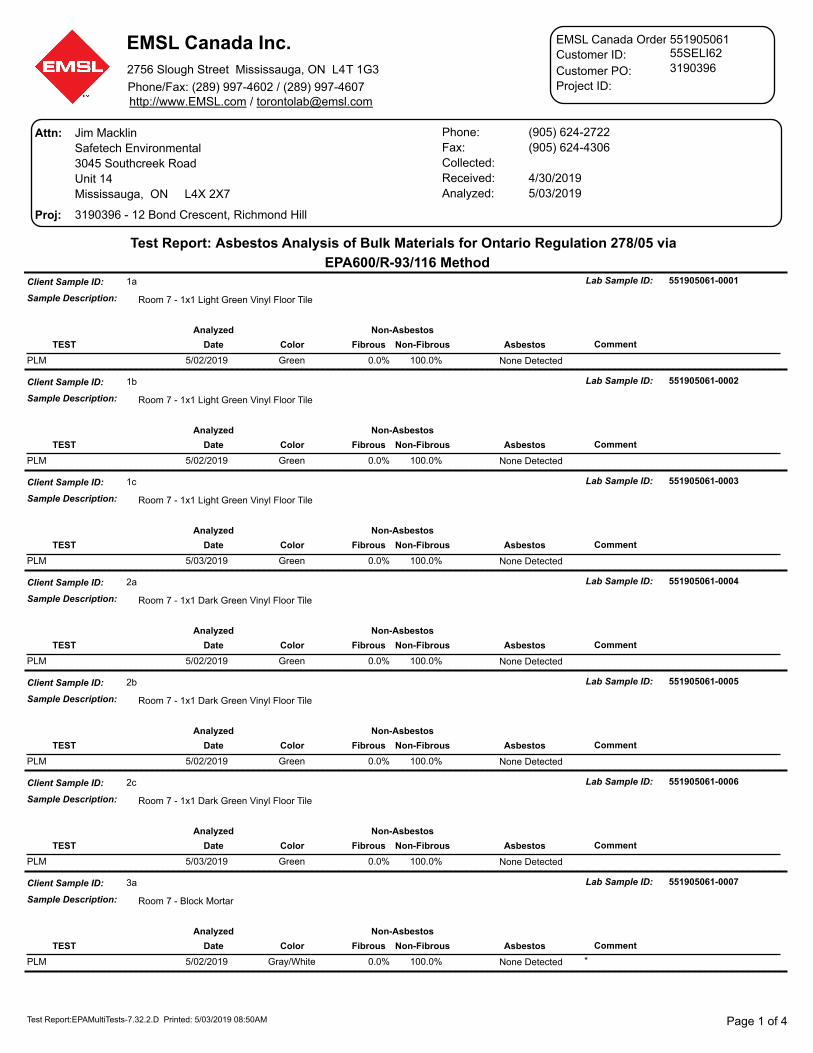
EMSL Canada Inc.
2756 Slough Street Mississauga, ON L4T 1G3
Phone/Fax: (289) 997-4602 / (289) 997-4607http://www.EMSL.com / [email protected]
55SELI62551905061
3190396
EMSL Canada Order ID:
Customer ID:
Customer PO:
Project ID:
Attn:
Proj: 3190396 - 12 Bond Crescent, Richmond Hill
Phone: (905) 624-2722
Fax: (905) 624-4306
Collected:
Received: 4/30/2019
Analyzed: 5/03/2019
Jim Macklin
Safetech Environmental
3045 Southcreek Road
Unit 14
Mississauga, ON L4X 2X7
Test Report: Asbestos Analysis of Bulk Materials for Ontario Regulation 278/05 via
EPA600/R-93/116 Method
Client Sample ID:
Sample Description:
Lab Sample ID: 551905061-00011a
Room 7 - 1x1 Light Green Vinyl Floor Tile
DateTEST Non-Fibrous Asbestos CommentColor Fibrous
Non-AsbestosAnalyzed
5/02/2019 0.0% 100.0%PLM Green None Detected
Client Sample ID:
Sample Description:
Lab Sample ID: 551905061-00021b
Room 7 - 1x1 Light Green Vinyl Floor Tile
DateTEST Non-Fibrous Asbestos CommentColor Fibrous
Non-AsbestosAnalyzed
5/02/2019 0.0% 100.0%PLM Green None Detected
Client Sample ID:
Sample Description:
Lab Sample ID: 551905061-00031c
Room 7 - 1x1 Light Green Vinyl Floor Tile
DateTEST Non-Fibrous Asbestos CommentColor Fibrous
Non-AsbestosAnalyzed
5/03/2019 0.0% 100.0%PLM Green None Detected
Client Sample ID:
Sample Description:
Lab Sample ID: 551905061-00042a
Room 7 - 1x1 Dark Green Vinyl Floor Tile
DateTEST Non-Fibrous Asbestos CommentColor Fibrous
Non-AsbestosAnalyzed
5/02/2019 0.0% 100.0%PLM Green None Detected
Client Sample ID:
Sample Description:
Lab Sample ID: 551905061-00052b
Room 7 - 1x1 Dark Green Vinyl Floor Tile
DateTEST Non-Fibrous Asbestos CommentColor Fibrous
Non-AsbestosAnalyzed
5/02/2019 0.0% 100.0%PLM Green None Detected
Client Sample ID:
Sample Description:
Lab Sample ID: 551905061-00062c
Room 7 - 1x1 Dark Green Vinyl Floor Tile
DateTEST Non-Fibrous Asbestos CommentColor Fibrous
Non-AsbestosAnalyzed
5/03/2019 0.0% 100.0%PLM Green None Detected
Client Sample ID:
Sample Description:
Lab Sample ID: 551905061-00073a
Room 7 - Block Mortar
DateTEST Non-Fibrous Asbestos CommentColor Fibrous
Non-AsbestosAnalyzed
5/02/2019 0.0% 100.0%PLM Gray/White *None Detected
Test Report:EPAMultiTests-7.32.2.D Printed: 5/03/2019 08:50AM Page 1 of 4

EMSL Canada Inc.
2756 Slough Street Mississauga, ON L4T 1G3
Phone/Fax: (289) 997-4602 / (289) 997-4607http://www.EMSL.com / [email protected]
55SELI62551905061
3190396
EMSL Canada Order ID:
Customer ID:
Customer PO:
Project ID:
Test Report: Asbestos Analysis of Bulk Materials for Ontario Regulation 278/05 via
EPA600/R-93/116 Method
Client Sample ID:
Sample Description:
Lab Sample ID: 551905061-00083b
1st Floor - Corridor - Block Mortar
DateTEST Non-Fibrous Asbestos CommentColor Fibrous
Non-AsbestosAnalyzed
5/02/2019 0.0% 100.0%PLM Gray/White *None Detected
Client Sample ID:
Sample Description:
Lab Sample ID: 551905061-00093c
Gym - Block Mortar
DateTEST Non-Fibrous Asbestos CommentColor Fibrous
Non-AsbestosAnalyzed
5/03/2019 0.0% 100.0%PLM Gray None Detected
Client Sample ID:
Sample Description:
Lab Sample ID: 551905061-00104a
Room 7 - Interior Beige Caulking
DateTEST Non-Fibrous Asbestos CommentColor Fibrous
Non-AsbestosAnalyzed
5/02/2019 0.0% 0.33%99.7% ChrysotilePLM Grav. Reduction White
Client Sample ID:
Sample Description:
Lab Sample ID: 551905061-00114b
Store Room 9 - Interior Beige Caulking
DateTEST Non-Fibrous Asbestos CommentColor Fibrous
Non-AsbestosAnalyzed
5/02/2019 0.0% 0.30%99.7% ChrysotilePLM Grav. Reduction White
Client Sample ID:
Sample Description:
Lab Sample ID: 551905061-00124c
Room 8 - Interior Beige Caulking
DateTEST Non-Fibrous Asbestos CommentColor Fibrous
Non-AsbestosAnalyzed
5/02/2019 0.0% 0.45%99.5% ChrysotilePLM Grav. Reduction White
Client Sample ID:
Sample Description:
Lab Sample ID: 551905061-00135a
Boiler Room - Boiler Breeching Mastic
DateTEST Non-Fibrous Asbestos CommentColor Fibrous
Non-AsbestosAnalyzed
5/02/2019 0.0% 100.0%PLM Brown/Red None Detected
Client Sample ID:
Sample Description:
Lab Sample ID: 551905061-00145b
Boiler Room - Boiler Breeching Mastic
DateTEST Non-Fibrous Asbestos CommentColor Fibrous
Non-AsbestosAnalyzed
5/02/2019 0.0% 100.0%PLM Brown/Red None Detected
Client Sample ID:
Sample Description:
Lab Sample ID: 551905061-00155c
Boiler Room - Boiler Breeching Mastic
DateTEST Non-Fibrous Asbestos CommentColor Fibrous
Non-AsbestosAnalyzed
5/03/2019 0.0% 100.0%PLM Red None Detected
Test Report:EPAMultiTests-7.32.2.D Printed: 5/03/2019 08:50AM Page 2 of 4

EMSL Canada Inc.
2756 Slough Street Mississauga, ON L4T 1G3
Phone/Fax: (289) 997-4602 / (289) 997-4607http://www.EMSL.com / [email protected]
55SELI62551905061
3190396
EMSL Canada Order ID:
Customer ID:
Customer PO:
Project ID:
Test Report: Asbestos Analysis of Bulk Materials for Ontario Regulation 278/05 via
EPA600/R-93/116 Method
Client Sample ID:
Sample Description:
Lab Sample ID: 551905061-00166a
Gym Stage - Black Mastic (under floor tile)
DateTEST Non-Fibrous Asbestos CommentColor Fibrous
Non-AsbestosAnalyzed
5/02/2019 0.0% 100.0%PLM Black/Beige Layers inseparableNone Detected
Client Sample ID:
Sample Description:
Lab Sample ID: 551905061-00176b
Corridor (adj. library) - Black Mastic (under floor tile)
DateTEST Non-Fibrous Asbestos CommentColor Fibrous
Non-AsbestosAnalyzed
5/02/2019 0.0% 100.0%PLM Black None Detected
Client Sample ID:
Sample Description:
Lab Sample ID: 551905061-00186c
Storage (adj. girls change room) - Black Mastic (under floor tile)
DateTEST Non-Fibrous Asbestos CommentColor Fibrous
Non-AsbestosAnalyzed
5/03/2019 0.0% 100.0%PLM Black None Detected
Client Sample ID:
Sample Description:
Lab Sample ID: 551905061-00197a
Stairwell Vestibule (adj. Room 8 ) - Brick Mortar
DateTEST Non-Fibrous Asbestos CommentColor Fibrous
Non-AsbestosAnalyzed
5/02/2019 0.0% 100.0%PLM Gray None Detected
Client Sample ID:
Sample Description:
Lab Sample ID: 551905061-00207b
Storage (adj. stairwell) - Brick Mortar
DateTEST Non-Fibrous Asbestos CommentColor Fibrous
Non-AsbestosAnalyzed
5/02/2019 0.0% 100.0%PLM Gray None Detected
Client Sample ID:
Sample Description:
Lab Sample ID: 551905061-00217c
Central Stairwell - Brick Mortar
DateTEST Non-Fibrous Asbestos CommentColor Fibrous
Non-AsbestosAnalyzed
5/03/2019 0.0% 100.0%PLM Gray None Detected
Client Sample ID:
Sample Description:
Lab Sample ID: 551905061-00228a
Exterior - Black Window Putty
DateTEST Non-Fibrous Asbestos CommentColor Fibrous
Non-AsbestosAnalyzed
5/02/2019 3.0% 94.0% 3% ChrysotilePLM Black
Client Sample ID:
Sample Description:
Lab Sample ID: 551905061-00238b
Exterior - Black Window Putty
DateTEST Non-Fibrous Asbestos CommentColor Fibrous
Non-AsbestosAnalyzed
5/02/2019PLM Positive Stop (Not Analyzed)
Test Report:EPAMultiTests-7.32.2.D Printed: 5/03/2019 08:50AM Page 3 of 4

EMSL Canada Inc.
2756 Slough Street Mississauga, ON L4T 1G3
Phone/Fax: (289) 997-4602 / (289) 997-4607http://www.EMSL.com / [email protected]
55SELI62551905061
3190396
EMSL Canada Order ID:
Customer ID:
Customer PO:
Project ID:
Test Report: Asbestos Analysis of Bulk Materials for Ontario Regulation 278/05 via
EPA600/R-93/116 Method
Client Sample ID:
Sample Description:
Lab Sample ID: 551905061-00248c
Exterior - Black Window Putty
DateTEST Non-Fibrous Asbestos CommentColor Fibrous
Non-AsbestosAnalyzed
5/02/2019PLM Positive Stop (Not Analyzed)
Client Sample ID:
Sample Description:
Lab Sample ID: 551905061-00259a
Exterior - White Window Caulking
DateTEST Non-Fibrous Asbestos CommentColor Fibrous
Non-AsbestosAnalyzed
5/02/2019 0.0% 100%PLM Grav. Reduction None DetectedWhite
Client Sample ID:
Sample Description:
Lab Sample ID: 551905061-00269b
Exterior - White Window Caulking
DateTEST Non-Fibrous Asbestos CommentColor Fibrous
Non-AsbestosAnalyzed
5/02/2019 0.0% 100%PLM Grav. Reduction None DetectedWhite
Client Sample ID:
Sample Description:
Lab Sample ID: 551905061-00279c
Exterior - White Window Caulking
DateTEST Non-Fibrous Asbestos CommentColor Fibrous
Non-AsbestosAnalyzed
5/02/2019 0.0% 100%PLM Grav. Reduction None DetectedWhite
PLM: (*) layers combined prior to analysis at client request
Analyst(s):
PLM (13)Ioana Taina
PLM Grav. Reduction (2)Kira Ramphal
PLM Grav. Reduction (4)Michelle Lung
PLM (6)Shorthri Kalikutty
Matthew Davis or other approved signatory
or Other Approved Signatory
Reviewed and approved by:
None Detected = <0.1%. EMSL maintains liability limited to cost of analysis. This report relates only to the samples reported above and may
not be reproduced, except in full, without written approval by EMSL. EMSL bears no responsibility for sample collection activities or analytical
method limitations. Interpretation and use of test results are the responsibility of the client. Samples received in good condition unless
otherwise noted. This report must not be used to claim product endorsement by NVLAP of any agency of the U.S. Government.
Samples analyzed by EMSL Canada Inc. Mississauga, ON NVLAP Lab Code 200877-0Initial report from: 05/03/201908:50:04
Test Report:EPAMultiTests-7.32.2.D Printed: 5/03/2019 08:50AM Page 4 of 4

Appendix D: Laboratory Certificate of Analysis – Lead

ConcentrationAnalyzed Weight RDL LeadClient SampleDescription Collected
Test Report: Lead in Paint Chips by Flame AAS (SW 846 3050B/7000B)*
EMSL Canada Inc.2756 Slough Street, Mississauga, ON L4T 1G3Phone/Fax: (289) 997-4602 / (289) 997-4607http://www.EMSL.com [email protected]
Attn: James MacklinSafetech Environmental3045 Southcreek RoadUnit 14Mississauga, ON L4X 2X7
Received: 04/30/19 3:28 PM
3190396 - 12 Bond Crescent, Richmond Hill
Fax: (905) 624-4306Phone: (905) 624-2722
Project:
Collected:
551905069CustomerID: 55SELI62CustomerPO: 3190396ProjectID:
EMSL Canada Or
Site: Room 7 - Off White Paint (Block)0.057 % wt5/1/2019 0.2452 g
551905069-00010.0082L-01 % wt
Site: Boiler Room - Grey Paint (Concrete)0.037 % wt5/1/2019 0.2500 g
551905069-00020.0080L-02 % wt
Site: Gym Stage - Black Paint (Floor Tile)<0.0081 % wt5/1/2019 0.2463 g
551905069-00030.0081L-03 % wt
Site: Storage Room 9 - Off White Paint (Block)0.062 % wt5/1/2019 0.2446 g
551905069-00040.0082L-04 % wt
Page 1 of 1Test Report PB w/RDL-2.0.0.0 Printed: 5/3/2019 9:46:28 AM
Rowena Fanto, Lead Supervisoror other approved signatory
*Analysis following Lead in Paint by EMSL SOP/Determination of Environmental Lead by FLAA. Reporting limit is 0.010 % wt based on the minimum sample weight per our SOP. Unless noted, results in this report are not blank corrected. This report relates only to the samples reported above and may not be reproduced, except in full, without written approval by EMSL. EMSL bears no responsibility for sample collection activities. Samples received in good condition unless otherwise noted. "<" (less than) result signifies that the analyte was not detected at or above the reporting limit. Measurement of uncertainty is available upon request. The QC data associated with the sample results included in this report meet the recovery and precision requirements unless specifically indicated otherwise. Definitions of modifications are available upon request.Samples analyzed by EMSL Canada Inc. Mississauga, ON A2LA Accredited Cert #2845.08; AIHA-LAP, LLC - ELLAP #196142
Initial report from 05/03/2019 09:46:28

Appendix E: Methodology

A. METHODOLOGY
The presence of hazardous materials was assessed by visual inspection. For the purpose of this assessment and this document, hazardous materials include designated substances as well as other chemical, biological and environmental hazards as defined below:
• Designated Substances (as prescribed by Ontario Regulation 490/09): • Acrylonitrile, Arsenic, Asbestos, Benzene, Coke Oven Emissions,
Ethylene Oxide, Isocyanates, Lead, Mercury, Silica and Vinyl Chloride.
• Other Hazardous Materials: • Chemical Hazards – Urea Formaldehyde Foam Insulation (UFFI) • Biological Hazards – Mould Contamination and Pest Infestation • Environmental Hazards – Polychlorinated Biphenyls (PCBs) and
Ozone Depleting & Global Warming Substances
Concealed locations such as above solid plaster or drywall ceilings, within plaster or drywall wall cavities, enclosed mechanical/pipe shafts and bulkheads, etc. were not investigated, unless otherwise stated in Section 1.3. Similarly, motors, blowers, electrical panels, etc., were not de-energized or disassembled to examine concealed conditions. Building materials that are not detailed within this assessment due to inaccessibility at the time of our site visit and/or uncovered during renovation/demolition activities should be assessed by a qualified person prior to their disturbance.
Bulk sampling followed by laboratory analysis was also conducted to confirm the presence/absence of select hazardous materials. Bulk sampling was limited to asbestos in building materials and lead in paint on building finishes (if flaking paint was present). All other hazardous materials were identified by visual inspection only. Where possible, observations regarding the location, quantity and condition of the hazardous materials identified were made in order to determine the potential for exposure and provide appropriate recommendations for remedial action, if necessary. Specific methodology for each individual hazardous material assessed is further detailed below. Neighborhood
A.1 Designated Substances
A.1.1 Asbestos
A visual inspection for the presence of both friable and non-friable asbestos-containing material (ACM) was performed in the subject area.
If an existing asbestos survey was available for review, Safetech relied on the information present. Building materials that were visually similar to materials previously tested and that were confirmed to be either ACM or non-ACM were considered to have consistent content and were not re-sampled. Additional sampling was only conducted where the investigator believed a need existed.

Bulk samples of building materials suspected to contain asbestos were retrieved by Safetech only for materials that were deemed to have a potential to be disturbed as part of the construction project. Some suspect materials may not have been sampled during our investigation. Bulk samples were retrieved in accordance with Section 3 and Table 1 of Ontario Regulation 278/05, “Designated Substance – Asbestos on Construction Projects and in Buildings and Repair Operations”. The number of samples collected for each material was based on the type and quantity of the material present in the subject area. Each individual sample was placed in a labeled zip-lock bag for transportation to an independent laboratory (EMSL). EMSL is accredited by the National Voluntary Laboratory Accreditation Program (NVLAP) for bulk asbestos fiber analysis.
Analysis for asbestos content was performed by the independent laboratory in accordance with the U.S. Environmental Protection Agency (EPA) Test Method EPA/600/R-93-116: Method for the Determination of Asbestos in Bulk Building Materials (June 1993). This method identifies the asbestos fibre content of building materials using polarized light microscopy (PLM) analytical techniques, with confirmation of presence and type of asbestos made by dispersion staining optical microscopy. This analytical method meets the requirements set forth in Section 3 of O. Reg. 278/05.
In accordance with O. Reg. 278/05, an asbestos-containing material is defined as material that contains 0.5 per cent or more asbestos by dry weight. The laboratory was instructed to conduct “stop-positive” analysis for all materials. If a sample was found to be asbestos-containing no further analysis was conducted for samples taken from the same homogeneous material.
Locations where ACM have been identified are detailed in this report. Recommendations pertaining to ACM were made based on the friability, accessibility and condition of the material in conjunction with the potential for the planned renovation work to disturb the ACM.
A.1.2 Assessment of Asbestos-Containing Building Materials
Accessibility, Condition and Action (Priority) ratings for individual items, or defined areas were developed by SEL to determine remedial action plans specific to the facility’s needs.
A.1.2.1 Accessibility
Accessibility has been assessed as: (A) Accessible to all non-maintenance occupants of the building; (B) Accessible to maintenance staff without a ladder; (C) Accessible to maintenance staff with a ladder and exposed to view without moving a building component; (D) Accessible to maintenance staff with a ladder and concealed from view due to a building component; (E) Not accessible without demolition or removal of fixed building components or building systems

A.1.2.2 Condition
The condition of asbestos-containing materials identified in the subject area was assessed as Good (G), Fair (F) or Poor (P). The assessment criteria used to determine condition is dependent on material characteristics, such as friability. The following table summarizes the criteria used by Safetech to evaluate the condition of ACM.
Sprayed Fireproofing, Sprayed Insulation and Sprayed Texture Finishes
Good
• Surface shows no significant signs of damage, deterioration, or delamination (i.e. <1%).
• Unencapsulated or unpainted fireproofing or texture finishes, where no delamination or damage is observed.
• Encapsulated fireproofing or texture finishes where encapsulation applied after damage or fallout.
Fair • Not utilized as part of condition assessment for these materials.
Poor • Greater than 1% damage, delamination, or deterioration to
surface.
• In areas where damage exists in isolated locations, both Good and Poor may be applicable.
Mechanical Insulation (boilers, breeching, ductwork, piping, tanks, equipment, etc.)
Good
• Insulation completely covered in jacketing and exhibits no evidence of damage or deterioration.
• Jacketing may have minor damage (i.e. scuffs or stains), but is not penetrated.
Fair
• Minor penetrating damage to jacketed insulation (cuts, tears, nicks, deterioration or delamination).
• Undamaged insulation that had never been jacketed.
• Insulation is exposed but not showing surface disintegration.
• Extent of missing insulation ranges from minor to none.
• Damage that can be repaired.
Poor
• Original insulation jacket is missing, damaged, deteriorated, or delaminated.
• Insulation is exposed and significant areas have been dislodged.
• Damage that cannot be easily repaired.
Non-Friable and Potentially Friable Materials (includes materials such as plaster finishes,
drywall compound, ceiling tiles, asbestos cement products, vinyl asbestos tile and asbestos paper
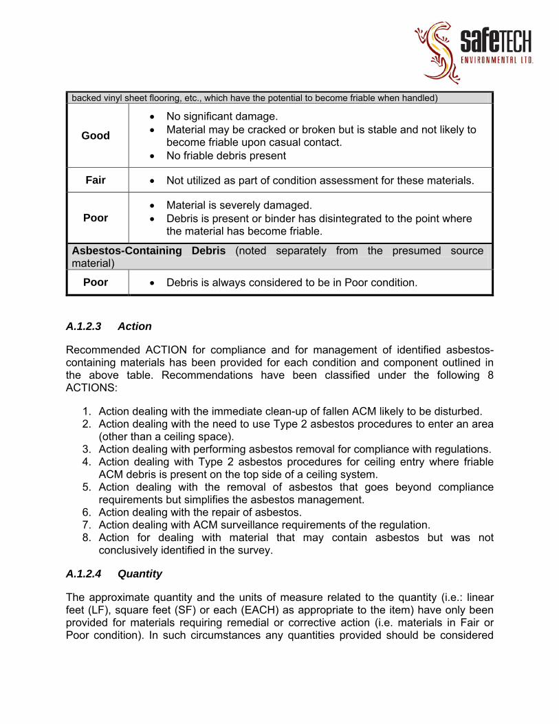
backed vinyl sheet flooring, etc., which have the potential to become friable when handled)
Good
• No significant damage.
• Material may be cracked or broken but is stable and not likely to become friable upon casual contact.
• No friable debris present
Fair • Not utilized as part of condition assessment for these materials.
Poor • Material is severely damaged.
• Debris is present or binder has disintegrated to the point where the material has become friable.
Asbestos-Containing Debris (noted separately from the presumed source material)
Poor • Debris is always considered to be in Poor condition.
A.1.2.3 Action
Recommended ACTION for compliance and for management of identified asbestos-containing materials has been provided for each condition and component outlined in the above table. Recommendations have been classified under the following 8 ACTIONS:
1. Action dealing with the immediate clean-up of fallen ACM likely to be disturbed. 2. Action dealing with the need to use Type 2 asbestos procedures to enter an area
(other than a ceiling space). 3. Action dealing with performing asbestos removal for compliance with regulations. 4. Action dealing with Type 2 asbestos procedures for ceiling entry where friable
ACM debris is present on the top side of a ceiling system. 5. Action dealing with the removal of asbestos that goes beyond compliance
requirements but simplifies the asbestos management. 6. Action dealing with the repair of asbestos. 7. Action dealing with ACM surveillance requirements of the regulation. 8. Action for dealing with material that may contain asbestos but was not
conclusively identified in the survey.
A.1.2.4 Quantity
The approximate quantity and the units of measure related to the quantity (i.e.: linear feet (LF), square feet (SF) or each (EACH) as appropriate to the item) have only been provided for materials requiring remedial or corrective action (i.e. materials in Fair or Poor condition). In such circumstances any quantities provided should be considered
rough estimates only and should not be solely relied upon for bidding purposes. It is the responsibility of the selected Contractor to obtain actual quantities.
A.2 Lead
If paint samples were collected, they would be collected by scraping the paint down to the base material substrate to ensure collection of all layers of paint. Care would be taken to avoid collection of the underlying substrate to reduce analytical substrate matrix interference.
If collected, paint samples would be submitted to an independent laboratory for the determination of lead content. The laboratory would participate in and accredited by the EPA (U.S. Environmental Protection Agency) for analysis of lead in paint chips through the American Industrial Hygiene Association (AIHA) Environmental Lead Laboratory Accreditation Program (ELLAP). Analysis would be conducted by the laboratory following the EPA “Test Methods for Evaluating Solid Waste, Physical/Chemical Methods” (SW-846), Method 7000B “Flame Atomic Absorption Spectrophotometry”. Result of analysis would be reported by the laboratory as the percentage of lead by weight of the total sample (% by wt.).
The presence of lead in other materials, such as lead sheeting, pigmented mortar, lead piping, lead solder, etc. would be noted where observed but not sampled to verify lead content. Lead can be present in these materials to varying degrees, depending on their age of application (refer to Appendix F for additional details) and should be considered lead-containing until proven otherwise.
A.3 Mercury
The type, quantity and location of mercury-containing equipment and devices in the subject area were determined by visual inspection based on appearance, age and knowledge of historical uses. Sampling for mercury-containing building materials and dismantling of suspect mercury-containing equipment was not performed. Where possible, attempts were made to verify the presence/absence of mercury by gathering additional information such as equipment model number, serial number, etc.
A.4 Silica
The presence of crystalline silica in building materials was determined through visual inspection of building materials only, based on knowledge of the historic use of silica-containing materials in certain building materials. Sampling to verify the presence/absence of silica in building materials was not performed.
A.5 Other Designated Substances
Other designated substances (i.e. acrylonitrile, arsenic, benzene, coke oven emissions, ethylene oxide, isocyanates, and vinyl chloride) are typically not expected to be

encountered in building materials as significant constituents or in a form that would represent an exposure concern. These substances were not included in our assessment unless specific information regarding their use (e.g. in a manufacturing process) was provided to us. Please refer to Appendix F for information regarding where these designated substances are typically found or used. No sampling for these designated substances was performed.
A.6 Other Hazardous Materials
A.6.1 Chemical Hazards
A.6.1.1 Urea Formaldehyde Foam Insulation (UFFI)
A visual inspection to evaluate the possible presence of Urea Formaldehyde Foam Insulation (UFFI) was conducted in the subject area. Our visual inspection was limited to looking for evidence of possible UFFI installation (i.e. repaired nozzle holes in walls) and overspray at wall/ceiling joints, etc. No destructive testing or material sampling was conducted as part of our assessment.
A.7 Biological Hazards
A.7.1.1 Mould Contamination
A visual inspection to determine the possibility of mould growth was conducted in the subject area. Our assessment was limited to looking for evidence of mould growth and water damage (staining, material deterioration, efflorescence, etc.) on the surface of building materials, which may be an indicator of hidden mould growth. No moisture content readings of building materials were taken to determine their current condition. Additionally, destructive testing to confirm the presence/absence of hidden mould growth and material sampling to verify the presence/absence of mould on suspect surfaces was beyond the scope of this assessment.
A.7.1.2 Pest Infestation
The presence and extent of pest infestation in the subject area was based on visually inspecting for evidence of significant pest activity, including signs of nesting, droppings/fecal accumulation, dead insects/carcass accumulation, etc. Evidence of minor pest presence was not considered to be indicative of pest infestation.
A.8 Environmental Hazards
A.8.1 Polychlorinated Biphenyls (PCBs)
The presence of PCB-containing electrical equipment in the subject area was identified through visual inspection and knowledge of the timeline of historical use.

For stand-alone transformers and capacitors, information from the manufacturer nameplate (such as the date of manufacture, dielectric fluid trade name or “Type Number”, etc.) was gathered, where possible, to further evaluate if the equipment may contain PCBs. This information was then compared to the information provided in the Environment Canada document entitled “Handbook on PCB’s in Electrical Equipment” (Third Edition, April 1988) to aid in identification. Transformers and capacitors confirmed to be manufactured after 1979 were assumed to not contain PCBs. If appropriate information could not be obtained it was assumed that the transformer or capacitor contained PCBs.
For fluorescent light ballasts, a representative number of fixtures were inspected, if possible, for assessment areas that were constructed prior to 1980 and where there was no history or evidence of a complete lighting retrofit. The light fixtures were examined by removing any lenses and ballast covers to expose the ballast and identify information such as ballast make, model number, serial number, and date code. This information was then compared to the information provided in the Environment Canada document entitled “Identification of Lamp Ballasts Containing PCBs” (Report EPS 2/CC/2 (revised) August 1991) to aid in identification. Ballasts that could not be confirmed Non-PCB-containing were assumed to contain PCBs. The light fixtures were not de-energized and ballasts were not removed to obtain manufacturer information that may be on the back of the ballast. If visual confirmation of ballast type could not be made it was assumed that light fixtures in areas constructed prior to 1980 that have not undergone a complete lighting retrofit have PCB-containing ballasts until proven otherwise.
No sampling of materials or fluids within equipment was conducted to verify the presence/absence of PCBs. Inspection and testing of other materials for PCB content, including (but not limited to) caulking, asphalt, oil-based paint, plastics, switches, electric cables and hydraulic fluids was beyond the scope of our assessment.
A.8.2 Ozone Depleting and Global Warming Substances
The presence of fixed equipment likely to contain ozone-depleting substances (ODS) and/or global-warming substances (GWS) was identified through visual inspection and knowledge of the timeline of historical use. This included equipment such as chillers, air-conditioners, walk-in refrigeration and freezer units and fixed dry-chemical fire extinguishers, where chemicals such as hydrochlorofluorocarbons (HCFCs), hydrofluorocarbons (HFCs) or halons may be present. Where possible, information regarding the type and quantity of refrigerant present was obtained from the manufacturer nameplate. Our visual assessment was limited to fixed equipment in the subject area and did not include portable equipment such as stand-alone refrigerators, freezers, water coolers, air-conditioners and fire extinguishers, etc.

P.A.C.E. Academy for Gifted Students Phase 1 Interior Renovations 00 41 00 MCA File No. 18054 Bid Form
00 41 00 - 1
May 30, 2019
Project No.: 18054
1. Project: P.A.C.E. Academy for Gifted Students Phase 1 Interior Renovations (Name) 12 Bond Crescent, Richmond Hill (Location)
2. Submitted to: P.A.C.E. Academy for Gifted Students (Owner) 12 Bond Crescent (Address) Richmond Hill, Ontario (City, Province, Postal Code)
3. From Bidder: (Legal Name)
........................................................................................................................................................ (Address)
........................................................................................................................................................ (City, Province, Postal Code)
4. Bid Price: We, the undersigned, having examined the Bid Documents as listed in Appendix B-1 of this Bid Form, and
Addendum No. to Addendum No. inclusive, all as issued by MC Architects Inc., and having
visited the Place of the Work, and examined all conditions, circumstances, and limitations affecting the Work,
[hereby offer to enter into a Contract with the Owner to perform the Work required by the Bid Documents for
the stipulated price of:
$ , in Canadian dollars, excluding Value Added Taxes (HST).] (Amount in figures)

P.A.C.E. Academy for Gifted Students Phase 1 Interior Renovations 00 41 00 MCA File No. 18054 Bid Form
00 41 00 - 2
May 30, 2019
5. Declarations: We, the undersigned, hereby declare that: .1 we agree to perform the Work, inclusive of mobilization time, in compliance with the required
completion schedule stated in the Bid Documents; .2 we have arrived at this bid without collusion with any competitor, and that no person, firm, or
corporation other than the undersigned has any interest in this Bid or in the proposed Contract for which this Bid is made;
.3 this Bid is open to acceptance for a period of sixty (60) days from the date of Bid submission;
.4 our combined overhead and profit mark-up on extras to the Contract shall not exceed ten percent (10%) for our own work, and five percent (5%) for our Subcontractors= work;
.5 our Subcontractors= combined overhead and profit mark-up on extras to the Contract shall not exceed ten percent (10%) for their own work;
.6 attached to this bid is a Bid Bond issued by:
.........................................................................................................................................................................
in the amount of $ ......................................................................................................................................... (We understand no other form of Bid Security is acceptable);
.7 attached to this bid is a separate Agreement to Bond issued by:
......................................................................................................................................................................... undertaking to provide the bonds required by the Bid Documents;
.8 attached to this bid is a signed AUndertaking of Insurance@ issued by:
......................................................................................................................................................................... stating their intention to provide insurance in accordance with the Bid Documents; and
.9 we shall submit the Supplementary Bid Form as required by the Instructions to Bidders

P.A.C.E. Academy for Gifted Students Phase 1 Interior Renovations 00 41 00 MCA File No. 18054 Bid Form
00 41 00 - 3
May 30, 2019
6. Signatures: Signed and Submitted for and on behalf of:
.................................................................................................. (Name of Bidder - company name)
.................................................................................................. (Name and Title of authorized signing officer)
.................................................................................................. (Signature of authorized signing officer)
.................................................................................................. (Name and Title of witness)
.................................................................................................. (Signature of Witness)
.................................................................................................. (Name and Title of authorized signing officer)
.................................................................................................. (Signature of authorized signing officer)
.................................................................................................. (Name and Title of witness)
.................................................................................................. (Signature of Witness) (Apply Seal Above)
Dated this day of , 20
Note: Affix corporate seal as required by Bid Documents.

P.A.C.E. Academy for Gifted Students Phase 1 Interior Renovations 00 41 00 MCA File No. 18054 Bid Form
00 41 00 - 4
May 30, 2019
APPENDIX B1 - LIST OF SUBCONTRACTORS
The following is the List of Subcontractors referred to in Document 00 21 00 - Instructions to Bidders, and is submitted by:
.................................................................................................................................................................................... to: (Bidder) (Owner)
dated ....................................................... , and which is an integral part of the Bid Form.
We, the above-named bidder, propose to use the Subcontractors named below. We declare that: .1 this list forms an integral part of the Bid Form; .2 no changes to the list shall be made without the Consultant=s express written permission; .3 no Subcontractor or Supplier listed below will be accepted who cannot provide the specified
manufacturer=s Product named in the Specifications; .4 each Subcontractor is listed by their proper legal name; and .5 we have contacted each Subcontractor on this list and have ascertained to our satisfaction that those
named are fully acquainted with the extent and nature of the work involved and of the proposed construction schedule, that they shall execute the work reliably and competently in conformance with the requirements of the Contract Documents, and that they shall provide bonds as specified.
The following work will be performed or provided by Subcontractors only and coordinated by the Bidder. This work shall not be performed by the Bidder=s own forces. Only one Subcontractor name shall be listed for each section of work.
SECTION OF WORK NAME OF SUBCONTRACTOR
Asbestos Abatement ..................................................................................................................... Demolition ..................................................................................................................... Masonry ..................................................................................................................... Mechanical ..................................................................................................................... Electrical .....................................................................................................................
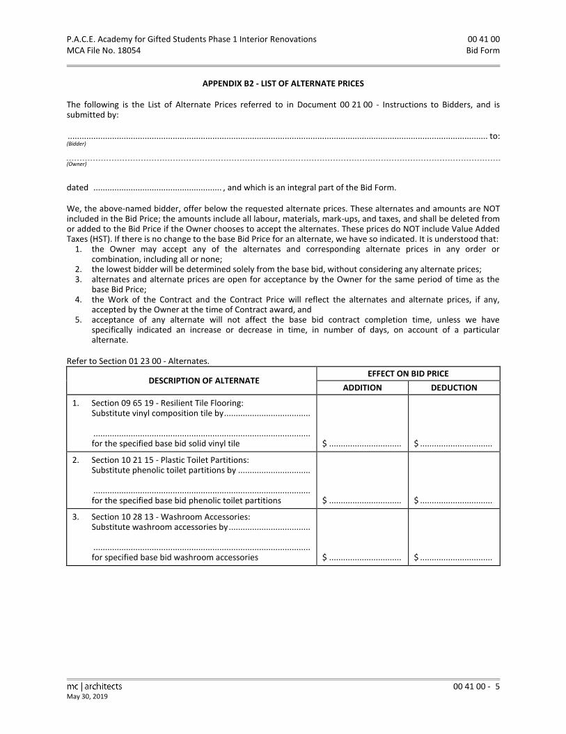
P.A.C.E. Academy for Gifted Students Phase 1 Interior Renovations 00 41 00 MCA File No. 18054 Bid Form
00 41 00 - 5
May 30, 2019
APPENDIX B2 - LIST OF ALTERNATE PRICES
The following is the List of Alternate Prices referred to in Document 00 21 00 - Instructions to Bidders, and is submitted by:
.................................................................................................................................................................................... to: (Bidder) (Owner)
dated ....................................................... , and which is an integral part of the Bid Form.
We, the above-named bidder, offer below the requested alternate prices. These alternates and amounts are NOT included in the Bid Price; the amounts include all labour, materials, mark-ups, and taxes, and shall be deleted from or added to the Bid Price if the Owner chooses to accept the alternates. These prices do NOT include Value Added Taxes (HST). If there is no change to the base Bid Price for an alternate, we have so indicated. It is understood that:
1. the Owner may accept any of the alternates and corresponding alternate prices in any order or combination, including all or none;
2. the lowest bidder will be determined solely from the base bid, without considering any alternate prices; 3. alternates and alternate prices are open for acceptance by the Owner for the same period of time as the
base Bid Price; 4. the Work of the Contract and the Contract Price will reflect the alternates and alternate prices, if any,
accepted by the Owner at the time of Contract award, and 5. acceptance of any alternate will not affect the base bid contract completion time, unless we have
specifically indicated an increase or decrease in time, in number of days, on account of a particular alternate.
Refer to Section 01 23 00 - Alternates.
DESCRIPTION OF ALTERNATE EFFECT ON BID PRICE
ADDITION DEDUCTION
1. Section 09 65 19 - Resilient Tile Flooring: Substitute vinyl composition tile by .....................................
............................................................................................. for the specified base bid solid vinyl tile
$ ...............................
$ ...............................
2. Section 10 21 15 - Plastic Toilet Partitions: Substitute phenolic toilet partitions by ...............................
............................................................................................. for the specified base bid phenolic toilet partitions
$ ...............................
$ ...............................
3. Section 10 28 13 - Washroom Accessories: Substitute washroom accessories by ...................................
............................................................................................. for specified base bid washroom accessories
$ ...............................
$ ...............................

P.A.C.E. Academy for Gifted Students Phase 1 Interior Renovations 00 41 00 MCA File No. 18054 Bid Form
00 41 00 - 6
May 30, 2019
APPENDIX B3 - LIST OF ITEMIZED PRICES
The following is the List of Itemized Prices referred to in Document 00 21 00 - Instructions to Bidders, and is submitted by:
.................................................................................................................................................................................... to: (Bidder) (Owner)
dated ....................................................... and which is an integral part of the Bid Form.
We, the above-named bidder, provide below the requested breakdown of items of Work; the work described and the amounts of these Itemized Prices are included in the Bid Price. The following Itemized Prices include all labour, materials, mark-ups, and taxes. These prices do NOT include Value Added Taxes (HST). It is understood that these Itemized Prices are provided for information purposes only and will not be used to modify the scope of the Work nor adjust the Bid Price.
DESCRIPTION OF ITEMIZED PRICE WORK ITEMIZED PRICE AMOUNT
1. Itemized Price No. 5: MECHANICAL PRICE The price to provide all work indicated on Mechanical Drawings and specified in Division 21, 22, and 23 of the Specifications.
$ ......................................................
2. Itemized Price No. 6: ELECTRICAL PRICE The price to provide all work indicated on Electrical Drawings and specified in Division 26, 27, and 28 of the Specifications.
$ ......................................................
END OF DOCUMENT

P.A.C.E. Academy for Gifted Students Phase 1 Interior Renovations 00 43 00 MCA File No. 18054 Supplementary Bid Form
00 43 00 - 1
May 30, 2019
Date: ............................................
Submitted by: ............................................................................................................................................................. (Name of Bidder) ............................................................................................................................................................. (Bidder’s Address) ............................................................................................................................................................. (City, Province, Postal Code)
Submitted to: P.A.C.E. Academy for Gifted Students (Owner)
1. In accordance with Document 00 21 00 - Instructions to Bidders and Document 00 41 00 - Bid Form, we, the undersigned, provide the Supplementary Bid Form appendices listed below and attached. (The information provided shall be considered an integral part of the Bid Form.)
2. The appendices attached are listed as follows: .1 Appendix S1 - Supplementary List of Subcontractors: Include the names of Subcontractors and the
portion(s) of the Work the Bidder will perform. .2 Appendix S2 - Proposed Alternate Form: Form for submission of Bidder - proposed alternates to
specified base bid Products. .3 Appendix S3 - List of Materials: Include a listing of Products and manufacturers of suppliers upon which
the Bid Price is based.
3. Supplementary Bid Form Signatures:
................................................................................... (Name Title of authorized signing officer) (Affix seal below)
................................................................................... (Signature of authorized signing officer)
................................................................................... (Name Title of authorized signing officer)
................................................................................... (Signature of authorized signing officer)

P.A.C.E. Academy for Gifted Students Phase 1 Interior Renovations 00 43 00 MCA File No. 18054 Supplementary Bid Form
00 43 00 - 2
May 30, 2019
APPENDIX S1 - SUPPLEMENTARY LIST OF SUBCONTRACTORS
The following is the Supplementary List of Subcontractors referred to in Article 2 of the Supplementary Bid Form submitted by:
.................................................................................................................................................................................... to: (Bidder) P.A.C.E. Academy for Gifted Students (Owner)
dated ....................................................... and which is an integral part of the Bid Form.
We, the above-named Bidder, propose to use the Subcontractors named below. We declare that: .1 this list forms an integral part of the Bid Form; .2 no changes to the list shall be made without the Consultant=s express written permission; .3 no Subcontractor or Supplier listed below will be accepted who cannot provide the specified
manufacturer=s Product named in the Specifications; .4 each Subcontractor is listed by their proper legal name; and .5 we have contacted each Subcontractor on this list and have ascertained to our satisfaction that those
named are fully acquainted with the extent and nature of the work involved and of the proposed construction schedule, that they shall execute the work reliably and competently in conformance with the requirements of the Contract Documents, and that they shall provide bonds as specified.
The following work will be performed or provided by Subcontractors and coordinated by the Bidder. Work to be performed by the Bidder=s own forces shall be noted AOWN FORCES@. Only one Subcontractor name shall be listed for each section of work.
SECTION OF WORK NAME OF SUBCONTRACTOR
Concrete ..................................................................................................................
Finish Carpentry ..................................................................................................................
Architectural Woodwork ..................................................................................................................
Fire Stopping and Smoke Seals ..................................................................................................................
Sealants ..................................................................................................................
Steel Doors and Frames ..................................................................................................................
Door Hardware Installation ..................................................................................................................
Glazing ..................................................................................................................
Ceramic Tile ..................................................................................................................
Acoustical Ceilings ..................................................................................................................
Resilient Tile and Sheet Flooring ..................................................................................................................
Painting ..................................................................................................................

P.A.C.E. Academy for Gifted Students Phase 1 Interior Renovations 00 43 00 MCA File No. 18054 Supplementary Bid Form
00 43 00 - 3
May 30, 2019
Toilet Partitions ..................................................................................................................
Washroom Accessories ..................................................................................................................

P.A.C.E. Academy for Gifted Students Phase 1 Interior Renovations 00 43 00 MCA File No. 18054 Supplementary Bid Form
00 43 00 - 4
May 30, 2019
APPENDIX S2 - PROPOSED ALTERNATE FORM
Submitted by: .................................................................................................................................................................. (Bidder)
to: P.A.C.E. Academy for Gifted Students .................................................................................................... (Owner)
Date: ..............................................................
1. We, the above-named bidder, submit, together with pertinent information attached to this form and as outlined in the Instructions to Bidders, the following proposed alternate to the specified work. We acknowledge that the amount listed below may be added to or subtracted from the Bid Price consistent with its acceptance by the Owner. If the proposed alternate is rejected we shall provide the specified Base Bid Product or employ the specified construction method, manufacturer, Supplier, or installer.
2. (List each proposed alternate on a separate sheet).
Proposed Alternate No. :
We propose to substitute for ...............................................................................................................................
...............................................................................................................................................................................
specified in Section ........................................................................................................... of the Specifications
with the following: ...............................................................................................................................................
...............................................................................................................................................................................
Reason for this proposed alternate: ....................................................................................................................
...............................................................................................................................................................................
Credit: $ .............................................................. Extra: $ ......................................................................
We submit attached hereto the following pertinent specification data:
...............................................................................................................................................................................
...............................................................................................................................................................................
...............................................................................................................................................................................
...............................................................................................................................................................................
...............................................................................................................................................................................

P.A.C.E. Academy for Gifted Students Phase 1 Interior Renovations 00 43 00 MCA File No. 18054 Supplementary Bid Form
00 43 00 - 5
May 30, 2019
APPENDIX S3 - LIST OF MATERIALS
The following is the List of Materials referred to in Article 2 of the Supplementary Bid Form submitted by:
to: (Bidder) (Owner)
Dated , and which is an integral part of the Bid Form.
The following is a list of materials, Products, and specified manufacturers or Suppliers upon which the Bid Price is based. The Bid Price shall include Products from one of the listed manufacturers or Suppliers. Bidders shall not add names nor alter this list in any way. If inappropriate substitutions are made by the Bidder on this list, the list shall be revised to conform to the Specifications and to the approval of the Consultant.
The Bidder shall identify the manufacturer or Supplier carried for each material by circling the appropriate name on the list. The Bidder shall circle only one manufacturer or Supplier name for any one item. If more than one name is circled or if no manufacturer or Supplier is identified for any one item, the Product manufacturer or Supplier listed in bold type shall be provided.
No changes to this list shall be made after bid submission without the Owner=s express written permission as issued by the Consultant.
SECTION
MATERIAL / PRODUCT
MANUFACTURER / SUPPLIER
06 41 05 Plastic Laminate Arborite Formica Nevamar Pionite Wilsonart
07 84 00 Fire Stopping A/D Fire Protection Systems Inc. Roxul Inc.
Smoke Seals 3M Canada Inc. Hilti (Canada) Corporation Tremco Construction Product
08 71 00 Door Hardware Empire Hardware Co. Ltd. Commercial Doors and Hardware Rivett Hardware Upper Canada Hardware
09 51 00 Acoustical Ceiling Tiles Armstrong World Industries Canada Ltd. CertainTeed Ceilings CGC Interiors

P.A.C.E. Academy for Gifted Students Phase 1 Interior Renovations 00 43 00 MCA File No. 18054 Supplementary Bid Form
00 43 00 - 6
May 30, 2019
Acoustical Suspension (non-fire rated T-bar) Armstrong World Industries Canada Bailey Metal Products Limited CertainTeed Ceilings CGC Interiors Chicago Metallic Corporation
Acoustical Suspension (fire-rated T-bar) CGC Interiors Bailey Metal Products Limited Chicago Metallic Corporation
Resilient Base (coved) Johnsonite Mannington Commercial Roppe Corporation
10 11 10 Markerboards Architectural School Products Delta Products Ltd. Global School Products Martack Specialties Ltd.
10 11 20 Tackboards Architectural School Products Delta Products Ltd. Global School Products Martack Specialties Ltd.
10 21 15 Plastic Toilet Partitions Bobrick Washroom Equipment Ampco Products, Inc. Buddsteel Architectural Products Saferail Products Inc. Global Toilet Partitions
10 28 13 Washroom Accessories Bobrick Washroom Equipment ASI Group Canada
Mirrors Bobrick Washroom Equipment ASI Group Canada
END OF DOCUMENT

P.A.C.E. Academy for Gifted Students Phase 1 Interior Renovations 00 52 00 MCA File No. 18054 Agreement Form and Definitions
00 52 00 - 1
May 30, 2019
1. AGREEMENT FORM AND DEFINITIONS
.1 Standard Construction Document - CCDC 2-2008, Stipulated Price Contract, English version, and as amended and modified below, forms the basis of Agreement between the Owner and Contractor including the Definitions of specific words and terms.
.2 Where these amendments, additions, and modifications specifically reference changes to the Agreement or Definitions, these amendments, additions, and modifications shall govern.
2. AMENDMENTS TO AGREEMENT FORM AND DEFINITIONS OF CCDC 2-2008
.1 AGREEMENT BETWEEN OWNER AND CONTRACTOR
.1 REF: ARTICLE A-5 PAYMENT .1 In paragraph 5.1, on the third line insert Aten@ in the blank space before the word Apercent@
and A10@ in the blank space between the parentheses. .2 Delete paragraph 5.1.2 and replace with the following:
A upon Substantial Performance of the Work, as certified by the Consultant, and one day after all lien rights have expired, pay to the Contractor any unpaid balance of holdback monies together with such Value Added Taxes as may be applicable to such payment, and@.
.3 In paragraph 5.1.3, revise the word Aissuance@ to Areceipt by the Owner@.
.4 In paragraph 5.3.1 on the seventh line, insert A[the Royal Bank of Canada]@ in the blank space.
.2 REF: ARTICLE A-6 RECEIPT OF AND ADDRESSES FOR NOTICES IN WRITING .1 Delete paragraph 6.1, and replace with the following:
A Notices in Writing between the parties or between them and the Consultant shall be considered to have been received by the addressee on the date of receipt if delivered by hand or by commercial courier or if sent during normal business hours by facsimile transmission and addressed as set out below. Such Notices in Writing will be deemed to be received by the addressee on the next business day if sent by facsimile transmission after normal business hours or if sent by overnight commercial courier. Such Notices in Writing will be deemed to be received by the addressee on the fifth Working Day following the date of mailing, if sent by pre-paid registered post, when addressed as set out below. An address for a party may be changed by Notice in Writing to the other party setting out the new address in accordance with this Article.@
.3 REF: ARTICLE A-7 LANGUAGE OF THE CONTRACT .1 Delete paragraph 7.1 in its entirety.
.4 REF: ARTICLE A-8 SUCCESSION .1 Add paragraph 8.2 as follows:
A Each party shall designate in writing an agent or employee who has authority to bind their principal in all matters relevant to the Contract including amendments thereto.@

00 52 00 P.A.C.E. Academy for Gifted Students Phase 1 Interior Renovations Agreement Form and Definitions MCA File No. 18054
00 52 00 - 2 May 30, 2019
.2 DEFINITIONS
.1 Add the following new Definitions: .1 Definition 27. Submittals
Submittals are documents or items required by the Contract Documents to be provided by the Contractor, such as: - Shop Drawings, samples, models, mock-ups to indicate details or characteristics, before the portion of the Work that they represent can be incorporated into the Work; and
- As-built drawings and manuals to provide instructions to the operation and maintenance of the Work.
.2 Definition 28. By Others By Others, when used in the Contract Documents, shall not mean by someone other than the Contractor. The only means by which something shown or specified shall be indicated as not being in the Contract is by the use of the initials AN.I.C.@ or the words Anot in (the) Contract@ or Aby Owner@.
.3 Definition 29. Exposed Exposed means visible by the occupants at completion of the Work, unless indicated otherwise. This includes roof area, mechanical and service spaces, inside cupboards and the like.
.4 Definition 30. Make Good Make Good means to restore new or existing work after being damaged, cut, or patched. Use materials identical to the original materials, with visible surfaces matching the appearance of the original surfaces in all details, and with no apparent junctions between new and original surfaces.
.5 Definition 31. Miscellaneous terms (by the Consultant) Where the words Reviewed, Instructed, Approved, Required, Directed, Permitted, Inspected, Ordered or similar words are used it shall be understood that they mean, unless the context provides otherwise, AReviewed by the Consultant@, AInstructed by the Consultant@, AApproved by the Consultant@, ARequired by the Consultant@, ADirected by the Consultant@, APermitted by the Consultant@, AInspected by the Consultant@, and AOrdered by the Consultant@.
.6 Definition 32. Miscellaneous terms (to the Consultant) Where the words Satisfactory, Submit, or similar words, or phases are used in the Contract Documents, it shall be understood that they mean, unless the context provides otherwise, ASatisfactory to the Consultant@ and ASubmit to the Consultant@.
END OF DOCUMENT

P.A.C.E. Academy for Gifted Students Phase 1 Interior Renovations 00 72 00 MCA File No. 18054 General Conditions
00 72 00 - 1
May 30, 2019
1. GENERAL CONDITIONS
.1 The General Conditions of Standard Construction Document - CCDC 2-2008, Stipulated Price Contract, English version, Parts 1 to 12 inclusive, are the General Conditions between the Owner and the Contractor.
2. SUPPLEMENTARY CONDITIONS
.1 Refer to Document 00 73 00 for amendments, additions, and modifications to these General Conditions.
END OF DOCUMENT

P.A.C.E. Academy for Gifted Students Phase 1 Interior Renovations 00 73 00 MCA File No. 18054 Supplementary Conditions
00 73 00 - 1
May 30, 2019
1. GENERAL CONDITIONS .1 The General Conditions, Parts 1 to 12 inclusive, of the Standard Construction Document CCDC 2-2008,
Stipulated Price Contract, English version, shall be considered complete only as amended and modified by the following Supplementary Conditions.
.2 Where these amendments, additions, and modifications specifically reference changes to the General Conditions, these amendments, additions, and modifications shall govern.
.3 Where a General Condition or paragraph of the General Conditions of the Stipulated Price Contract is deleted by these Supplementary Conditions, the numbering of the remaining General Conditions or paragraphs shall remain unchanged, and the numbering of the deleted item will be retained, unused.
2. SUPPLEMENTS TO GENERAL CONDITIONS
.1 REF: GC 1.1 CONTRACT DOCUMENTS
.1 In paragraph 1.1.2, add the following to the end of subparagraph 1.1.2.2: A ,except where the Consultant shall be indemnified as a third party beneficiary as provided in
subparagraphs 9.2.7.4, and 9.5.3.4 and in paragraph 12.1.3.@ .2 Add the following to the end of paragraph 1.1.6:
A The Specifications are divided into Divisions and the Divisions into Sections for the purpose of convenience and ready reference, but a Section may consist of the work of more than one trade Contractor or Supplier. The Specifications are intended to be read as a whole.@
.3 In paragraph 1.1.7, add new subparagraph 1.1.7.5 as follows: A In case of discrepancies, noted materials and annotations shall take precedence over graphic
indications in the Contract Documents.@ .4 Delete paragraph 1.1.8 and substitute the following:
A The Consultant on behalf of the Owner shall provide the Contractor without charge, only electronic Contract Documents in PDF format, exclusive of those required by jurisdictional authorities and the executed Contract Documents.@
.2 REF: GC 2.2 ROLE OF THE CONSULTANT
.1 In paragraph 2.2.9, at the end of the second line add the following sentence: A The Owner and the Contractor shall waive any claims against the Consultant arising out of the
making of such interpretations and findings in accordance with paragraphs 2.2.7, 2.2.8, and 2.2.9.@
.2 In paragraph 2.2.14, on the first line after the word Asubmittals@ delete the comma (,) and add the words Awhich are provided@.
.3 REF: GC 2.4 DEFECTIVE WORK
.1 In paragraph 2.4.1: .1 Add new subparagraph 2.4.1.1 as follows: A The Contractor shall rectify, in a manner acceptable to the Owner and the Consultant, all
defective work and deficiencies throughout the Work, whether or not they are specifically identified by the Consultant.@
.2 Add new subparagraph 2.4.1.2 as follows: A The Contractor shall prioritize the correction of any defective work which, in the sole discretion
of the Owner, adversely affects the day to day operation of the Owner.@
.4 REF: GC 3.1 CONTROL OF THE WORK .1 Add new paragraph 3.1.3 as follows:
A Prior to commencing individual procurement, fabrication, and construction activities, the Contractor shall verify, at the Place of the Work, all relevant measurements and levels necessary for proper and complete fabrication, assembly, and installation of the Work and

00 73 00 P.A.C.E. Academy for Gifted Students Phase 1 Interior Renovations Supplementary Conditions MCA File No. 18054
00 73 00 - 2 May 30, 2019
shall further carefully compare such field measurements and conditions with the requirements of the Contract Documents. Where dimensions are not included or contradictions exist or exact locations are not apparent, the Contractor shall immediately notify the Consultant in writing and obtain written instructions from the Consultant before proceeding with any part of the affected Work.@
.5 REF: GC 3.3 TEMPORARY WORK
.1 In paragraph 3.3.2, on the second line after the words Awhere required by law@, insert Aor by the Consultant@.
.6 REF: GC 3.4 DOCUMENT REVIEW
.1 Delete paragraph 3.4.1 and replace with the following: A The Contractor shall review the Contract Documents and shall report promptly to the
Consultant any error, inconsistency, or omission the Contractor may discover. Such review by the Contractor shall comply with the standard of care described in paragraph 3.14.1 of the Contract. Except for the Contractor=s obligation to make such review and report the result, the Contractor does not assume any responsibility to the Owner or to the Consultant for the accuracy of the Contract Documents. The Contractor shall not be liable for damage or costs resulting from such errors, inconsistencies, or omissions in the Contract Documents, which the Contractor could not reasonably have discovered. If the Contractor does discover any error, inconsistency, or omission in the Contract Documents, the Contractor shall not proceed with the work affected until the Contractor has received corrected or missing information from the Consultant.@
.7 REF: GC 3.5 CONSTRUCTION SCHEDULE
.1 In subparagraph 3.5.1.1, on the first line after the words Afirst application for payment,@ insert Aor the execution of the Contract to form part of the Construction Documents, whichever comes first,@.
.2 Add at the end of subparagraph 3.5.1.1: A This schedule shall enable the Owner and the Consultant to monitor the progress of the Work
on a weekly basis. The Contractor shall attend job site meetings every two weeks and any meetings of the Owner when reasonably called upon to do so to discuss the said schedule and subsequent progress of construction relating to said schedule.@
.3 In subparagraph 3.5.1.2, on the first line after the words Aon a monthly basis,@ add Aat a minimum or as required by the Consultant@.
.8 REF: GC 3.6 SUPERVISION
.1 In paragraph 3.6.1 on the first line after the words Awho shall be in@ insert Afull time@, and at the end of the third line insert Awhich shall be provided in writing.@
.9 REF: GC 3.7 SUBCONTRACTORS AND SUPPLIERS
.1 In subparagraph 3.7.1.1 add to the end of the second line Aincluding any warranties and service agreements which extend beyond the terms of this Contract.@
.2 In subparagraph 3.7.1.2 after the words Athe Contract Documents@ insert Aincluding required Bonding@.
.3 In paragraph 3.7.2, on the first line, delete the words Aif requested by the Owner@.
.10 REF: GC 3.8 LABOUR AND PRODUCTS .1 Add new paragraph 3.8.4 as follows:
A The Contractor is responsible for the safe on-site storage of Products and their protection (including Products to be installed under the Contract and supplied by the Owner and other contractors) in such ways as to avoid dangerous conditions or contamination to the Products

P.A.C.E. Academy for Gifted Students Phase 1 Interior Renovations 00 73 00 MCA File No. 18054 Supplementary Conditions
00 73 00 - 3
May 30, 2019
or other persons or property and in locations at the Place of the Work to the satisfaction of the Owner and the Consultant. The Owner shall provide all relevant information on the Products to be supplied by the Owner.@
.11 .REF: GC.3.10 SHOP DRAWINGS
.1 Delete the existing General Condition title ASHOP DRAWINGS@ and replace with ASHOP DRAWINGS AND OTHER SUBMITTALS@.
.2 In paragraphs 3.10.1, 3.10.2, 3.10.4, 3.10.7, 3.10.8, 3.10.9, 3.10.10, 3.10.11, and 3.10.12, after each instance of the words AShop Drawings@ add the words Aand Submittals@.
.3 Delete paragraph 3.10.3 and replace with the following: A Prior to the first application for payment, the Contractor and the Consultant shall jointly
prepare a schedule of the dates for submission and return of Shop Drawings and any Submittals.@
.4 In paragraph 3.10.12, on the second line delete the words Awith reasonable promptness so as to cause no delay in the performance of the Work@ and replace with Awithin 10 Working Days or such longer period as may be reasonably required@.
.12 .REF: GC 3.14 PERFORMANCE BY THE CONTRACTOR
.1 Add new General Condition GC 3.14 PERFORMANCE BY THE CONTRACTOR as follows: A 3.14.1 In performing the Contractor=s services and obligations under the Contract, the
Contractor shall exercise a standard of care, skill, and diligence that would normally be provided by an experienced and prudent Contractor supplying similar services for similar projects. The Contractor acknowledges and agrees that throughout the Contract, the Contractor=s obligations, duties, and responsibilities shall be interpreted in accordance with this standard. The Contractor shall exercise the same standard of due care and diligence in respect of any Products, personnel, or procedures which the Contractor may recommend to the Owner.
3.14.2 The Contractor further represents, covenants, and warrants to the Owner that: .1 the personnel the Contractor assigns to the Project are appropriately experienced;
and .2 the Contractor has a sufficient staff of qualified and competent personnel to replace
the Contractor=s designated supervisor and project manager, subject to the Owner=s approval, in the event of death, incapacity, removal, or resignation.@
.13 REF: GC 4.1 CASH ALLOWANCES
.1 Delete paragraph 4.1.4 and replace with the following: A Where the costs under a cash allowance exceed the amount of the allowance, unexpended
amounts from other cash allowances shall be reallocated, at the Consultant=s directions, to cover the shortfall.@
.2 Delete paragraph 4.1.5 and replace with the following: A The net amount of any unexpended cash allowance, after providing for any re-allocations as
contemplated in paragraph 4.1.4, shall be deducted from the Contract Price by Change Order.@ .3 Delete paragraph 4.1.7 and replace with the following:
A At the commencement of the Work, the Contractor shall prepare for the review and acceptance of the Owner and the Consultant, a schedule indicating the times, within the construction schedule referred to in GC 3.5, that items called for under cash allowances and items that are specified to be Owner purchased and Contractor installed or hooked up are required at the site to avoid delaying the progress of the Work.@
.4 Add new paragraph 4.1.8, as follows: A The Owner reserves the right to call, or to have the Contractor call, for competitive bids for
portions of the Work, to be paid for from cash allowances.@

00 73 00 P.A.C.E. Academy for Gifted Students Phase 1 Interior Renovations Supplementary Conditions MCA File No. 18054
00 73 00 - 4 May 30, 2019
.14 REF: GC 5.1 FINANCING INFORMATION REQUIRED OF THE OWNER .1 Add new paragraph 5.1.3 as follows:
A The Contractor acknowledges that this agreement is conditional upon the Owner obtaining the necessary approval and required funding from the Ministry of Education and Training, and that the Owner is not liable should such funding not be granted.@
.15 REF: GC 5.2 APPLICATION FOR PROGRESS PAYMENT
.1 In paragraph 5.2.4, on the first line, revise A15 calendar days@ to A20 calendar days@.
.2 Add new paragraph 5.2.8 as follows: A With the second and each subsequent application for payment, the Contractor shall submit a
Statutory Declaration, using the appropriate CCDC form.@
.16 REF: GC 5.3 PROGRESS PAYMENT .1 In paragraph 5.3.1:
.1 Delete subparagraph 5.3.1.1 in its entirety.
.2 In subparagraph 5.3.1.3, on the second line delete A20" and replace with A25". .2 Add new paragraph 5.3.2 as follows:
A There shall be no certification of payments after Substantial Performance of the Work until the Date of Completion of the Contract.@
.17 REF: GC 5.4 SUBSTANTIAL PERFORMANCE OF THE WORK
.1 In paragraph 5.4.1, at the end of the paragraph add the following: A The Contractor will proceed diligently to remedy and rectify all items contained on the
aforementioned list to the satisfaction of the Consultant and the Owner.@
.18 REF: GC 6.1 OWNER=S RIGHT TO MAKE CHANGES .1 Add new paragraph 6.1.3 as follows:
A The Contractor=s fee for overhead and profit for changes in the Work shall be calculated on the following basis: .1 combined overhead and profit mark-up on the Contractor=s work shall not exceed ten
percent (10%); .2 the Contractor=s combined overhead and profit mark-up on Subcontractors, work shall not
exceed five percent (5%); .3 combined overhead and profit mark-up charged by Subcontractors on their own work shall
not exceed ten percent (10%); .4 overhead and profit mark-up may be charged if a change in the Work results in a net
increase in the Contract Price; .5 overhead and profit shall not be charged if a change in the Work results in a net decrease in
the Contract Price; .6 where a change in the Work involves both additions and deletions, overhead and profit shall
apply only to the net increase in the Contract Price resulting from the change; .7 overhead and profit mark-ups shall be deemed to provide for payment in full for all items
that in the custom of the construction industry in Ontario are considered to be site or head office overhead and profit, supervision, and administration, and shall include, but is not limited to, the following:
.1 Contractor=s head office expenses; .2 Wages of Project managers, superintendents, assistants, watch persons, and
administrative personnel; .3 Temporary site office including costs for telephone and facsimile machine; .4 Small tools; .5 Insurance and bonding premiums; .6 As-built drawings;

P.A.C.E. Academy for Gifted Students Phase 1 Interior Renovations 00 73 00 MCA File No. 18054 Supplementary Conditions
00 73 00 - 5
May 30, 2019
.7 Clean-up and disposal of waste materials.@
.19 REF: GC 6.2 CHANGE ORDER .1 In paragraph 6.2.1, at the end of the paragraph add the following:
A Quotations submitted by the Contractor for any changes to the Work shall be accompanied by a complete itemized breakdown of all costs so that the total price can be properly assessed@.
.20 REF: GC 6.3 CHANGE DIRECTIVE
.1 In paragraph 6.3.6, delete subparagraph 6.3.6.3 and replace with the following: A The Contractor=s fee for overhead and profit shall be calculated as described under GC 6.1
OWNER=S RIGHT TO MAKE CHANGES.@
.21 REF: GC 6.4 CONCEALED OR UNKNOWN CONDITIONS .1 In subparagraph 6.4.1.1, on the second line after the words Athe Contract Documents@, insert Aas
determined by the Consultant@. .2 In subparagraph 6.4.1.2, on the third line, after the words Athe Contract Documents@, insert Aas
determined by the Consultant@. .3 Add new paragraph 6.4.5 as follows:
A The Contractor confirms that, prior to bidding the Project, the Contractor carefully investigated the Place of the Work and applied to that investigation the degree of care and skill described in paragraph 3.14.1, given the amount of time provided between the issue of the bid documents and the actual closing of bids, the degree of access provided to the Contractor prior to submission of bids, and the sufficiency and completeness of the information provided by the Owner. The Contractor is not entitled to compensation or to an extension of the Contract Time for conditions which could reasonably have been ascertained by the Contractor by such careful investigation undertaken prior to the submission of bids.@
.22 REF: GC 6.5 DELAYS
.1 In paragraph 6.5.1, at the end of the paragraph after the word Adelay@, add the following words: A , but excluding any consequential, indirect, or special damages@.
.2 Add new paragraph 6.5.6 as follows: A If the Contractor is delayed in the performance of the Work by an act or omission of the
Contractor or anyone employed or engaged by the Contractor directly or indirectly, or by any cause within the Contractor=s control, then the Contract Time shall be extended for such reasonable time as the Consultant may decide in consultation with the Contractor. The Owner shall be reimbursed by the Contractor for all reasonable costs incurred by the Owner as the result of such delay, including all services required by the Owner from the Consultant as a result of such delay by the Contractor and, in particular, the cost of the Consultant=s services during the period between the date of Substantial Performance of the Work stated in Article A-1 herein as the same may be extended through the provisions of these General Conditions and any later, actual date of Substantial Performance of the Work achieved by the Contractor.@
.23 REF: GC 6.6 CLAIMS FOR A CHANGE IN CONTRACT PRICE
.1 In paragraph 6.6.5: .1 On the second line after the words Aof the claim@ add: Aas noted in paragraph 6.6.3". .2 At the end of the paragraph, after the word Aparties@ add: Aand the Consultant@.
.24 REF: GC 7.1 OWNER=S RIGHT TO PERFORM THE WORK, TERMINATE THE CONTRACTOR=S RIGHT TO
CONTINUE WITH THE WORK OR TERMINATE THE CONTRACT .1 Add new subparagraph 7.1.3.4 as follows:
A An Aacceptable schedule@ as referred to in 7.1.3.2. of the General Conditions means a schedule approved by the Consultant and the Owner wherein the default can be corrected within the

00 73 00 P.A.C.E. Academy for Gifted Students Phase 1 Interior Renovations Supplementary Conditions MCA File No. 18054
00 73 00 - 6 May 30, 2019
balance of the Contract Time and shall not cause delay to any other aspect of the Work or the work of other contractors, and in no event shall it be deemed to give a right to extend the Contract Time.@
.25 REF: GC 7.2 CONTRACTOR=S RIGHT TO SUSPEND THE WORK OR TERMINATE THE CONTRACT
.1 Add new subparagraph 7.2.3.5 as follows: A The foregoing defaults in contractual obligations shall not apply to the withholding of
certificates or payments, or both, in accordance with the General Conditions, because of the Contractor=s failure to pay all legitimate claims promptly, nor because of the registration of liens against the Owner=s property, until such claims and liens are discharged.@
.2 Add new paragraph 7.2.6 as follows: A If the Contractor stops the Work or terminates the Contract as provided for in paragraph 7.2.1
to 7.2.5 above, he shall ensure the site and the Work is left in a safe, secure condition as required by Authorities Having Jurisdiction as well as the Contract Documents.@
.26 REF: GC 8.2 NEGOTIATION, MEDIATION AND ARBITRATION
.1 Add new paragraphs 8.2.9 to 8.2.14 as follows: A 8.2.9 Within five days of receipt of the notice of arbitration by the responding party under
paragraph 8.2.6, the Owner and the Contractor shall give the Consultant a written notice containing:
a) a copy of the notice of arbitration; b) a copy of Supplementary Conditions 8.2.9 to 8.2.14 of this Contract; and,
c) any claims or issues which the Contractor or the Owner, as the case may be, wishes to raise in relation to the Consultant arising out of the issues in dispute in the arbitration.
8.2.10 The Owner and the Contractor agree that the Consultant may elect, within ten days of receipt of the notice under paragraph 8.2.9, to become a full party to the arbitration under paragraph 8.2.6 if the Consultant:
a) has a vested or contingent financial interest in the outcome of the arbitration; b) gives the notice of election to the Owner and the Contractor before the
arbitrator is appointed; c) agrees to be a party to the arbitration within the meaning of the rules referred
to in paragraph 8.2.6; and, d) agrees to be bound by the arbitral award made in the arbitration. 8.2.11 If an election is made under paragraph 8.2.10, the Consultant may participate in the
appointment of the arbitrator and, notwithstanding the rules referred to in paragraph 8.2.6, the time period for reaching agreement on the appointment of the arbitrator shall begin to run from the date the respondent receives a copy of the notice of arbitration.
8.2.12 The arbitrator in the arbitration in which the Consultant has elected under paragraph 8.2.10 to become a full party may:
a) on application of the Owner or the Contractor, determine whether the Consultant has satisfied the requirements of paragraph 8.2.10; and,
b) make any procedural order considered necessary to facilitate the addition of the Consultant as a party to the arbitration.
8.2.13 The provisions of paragraph 8.2.9 shall apply mutatis mutandis to written notice to be given by the Consultant to any sub-consultant.
8.2.14 In the event of notice of arbitration given by a Consultant to a sub-consultant, the sub-consultant is not entitled to any election with respect to the proceeding as outlined in 8.2.10, and is deemed to be bound by the arbitration proceeding.@

P.A.C.E. Academy for Gifted Students Phase 1 Interior Renovations 00 73 00 MCA File No. 18054 Supplementary Conditions
00 73 00 - 7
May 30, 2019
.27 .REF: GC 9.1 PROTECTION OF WORK AND PROPERTY .1 In paragraph 9.1.1, delete subparagraph 9.1.1.1 and replace with the following:
A errors in the Contract Documents which the Contractor could not have discovered applying the standard of care described in paragraph 3.14.1;@.
.2 Delete paragraph 9.1.2 and replace with the following: A Before commencing any work, the Contractor shall determine the locations of all underground
utilities and structures indicated in the Contract Documents or that are discoverable from an inspection of the Place of the Work exercising the degree of care and skill described in paragraph 3.14.1.@
.28 REF: GC 9.2 TOXIC AND HAZARDOUS SUBSTANCES
.1 In paragraph 9.2.6, on the second line after the word Aresponsible@, add the following words: A or whether any toxic or hazardous substances or materials already at the Place of Work (and
which were then harmless or stored, contained, or otherwise dealt with in accordance with legal and regulatory requirements) were dealt with by the Contractor or anyone for whom the Contractor is responsible in a manner which does not comply with legal and regulatory requirements, or which threatens human health and safety or the environment, or material damage to the property of the Owner or others,@.
.2 In subparagraph 9.2.7.4, after the word AContractor@, add the words Aand the Consultant@.
.3 In paragraph 9.2.8, on the second line after the word Aresponsible@, add the following words: A or that any toxic or hazardous substances or materials already at the Place of the Work (and
which were then harmless or stored, contained, or otherwise dealt with in accordance with legal and regulatory requirements) were dealt with by the Contractor or anyone for whom the Contractor is responsible in a manner which does not comply with legal and regulatory requirements, or which threatens human health and safety or the environment, or material damage to the property of the Owner or others,@.
.29 REF: GC 9.4 CONSTRUCTION SAFETY
.1 In paragraph 9.4.1 on the first line delete the words ASubject to paragraph 3.2.2.2 of GC 3.2 - CONSTRUCTION BY OWNER OR OTHER CONTRACTORS, the@ and replace with the word AThe@.
.30 REF: GC 9.5 MOULD
.1 In subparagraph 9.5.3.4, after the word AContractor@ add the words Aand the Consultant@.
.31 REF: GC 10.2 LAWS, NOTICES, PERMITS, AND FEES .1 In paragraph 10.2.2 insert the following at the end of the paragraph:
A The Contractor shall pay construction damage deposits levied by the municipality in connection with the issuance of the building permit. The ABuilding Permit Copy@ of the Drawings and Specifications as approved by the Chief Building Official and issued as part of the Building Permit shall be reviewed by the Consultant for any requirements which could affect the Contract Documents. It shall then be kept on the job and maintained in good condition from commencement to completion of the Work. On completion of the Work this ABuilding Permit Copy@ shall be delivered in good condition to the Consultant.@
.2 In paragraph 10.2.5, on the first line delete the word AThe@ and replace with the words: ASubject to paragraph 3.14.1, the@.
.32 REF: GC 11.2 CONTRACT SECURITY
.1 Delete paragraph 11.2.1 and replace with the following: A The Contractor shall, within ninety (90) days of Bid closing and prior to Contract signing,
provide a fifty percent (50%) Performance Bond and a fifty percent (50%) Labour and Material Payment Bond. Bonds shall include for rectification of warranty items and shall continue to be in force for a period of two years beyond the date of Substantial Performance of the Work.@

00 73 00 P.A.C.E. Academy for Gifted Students Phase 1 Interior Renovations Supplementary Conditions MCA File No. 18054
00 73 00 - 8 May 30, 2019
.33 REF: GC 12.1 INDEMNIFICATION .1 In paragraph 12.1.1, add new subparagraph 12.1.1.3 as follows:
A The Contractor shall indemnify and hold harmless the Consultant and the Consultant=s agents and employees from and against claims, demands, losses, costs, damages, actions, suits, or proceedings by third parties that arise out of, or are attributable to, the Contractor=s performance of the Contract, provided such claims are attributable to bodily injury, sickness, disease, or death, or to injury to or destruction of tangible property, and caused by negligent acts or omissions of the Contractor or anyone for whose acts the Contractor may be liable, and made in writing within a period of 6 years from the date of Substantial Performance of the Work as set out in the certificate of Substantial Performance of the Work, or within such shorter such period as may be prescribed by any limitation statute of the province or territory of the Place of the Work.@
.2 In subparagraph 12.1.2.1, on the third and fourth lines after “GC 11.1 – INSURANCE,” revise to read as follows: “ the general liability insurance limit for one occurrence and aggregate limit within any policy
year referred to in CCDC 41 shall be increased from $ 5,000,000.00 to $ 10,000,000.00 in both instances.”
.34 REF: GC 12.3 WARRANTY
.1 In paragraph 12.3.2, on the first line delete the word AThe@ and replace with the words: ASubject
to paragraph 3.14.1, the@.
END OF DOCUMENT

P.A.C.E. Academy for Gifted Students Phase 1 Interior Renovations 01 00 00 MCA File No. 18054 General Requirements
01 00 00 - 1
May 30, 2019
PART 1 GENERAL
1.01 SECTION INCLUDES
.1 Work covered by Contract Documents.
.2 Cash Allowances.
.3 Contingency Allowance.
.4 Alternates.
.5 Project coordination and organization.
.6 Cutting and patching.
.7 Project meetings.
.8 Submittals.
.9 Schedules.
.10 Quality control.
.11 Construction facilities and temporary controls.
.12 Material and equipment.
.13 Project closeout.
1.02 RELATED SECTIONS
.1 Document 00 21 00 - Instructions to Bidders.
.2 Document 00 52 00 - Agreement Form and Definitions.
.3 Document 00 72 00 - General Conditions.
.4 Document 00 73 00 - Supplementary Conditions.
1.03 WORK COVERED BY CONTRACT DOCUMENTS
.1 Title and Description of the Work: The Work of this Contract is identified as P.A.C.E. Academy for Gifted Students Phase 1 – Interior Renovations and comprised of interior renovations including new partitioning, floor wall and ceiling finishes; along with associated structural mechanical and electrical work. The Project is located at 12 Bond Street, Richmond Hill Ontario.
.2 Contract Method: CCDC2 - 2008, Stipulated Price Contract, English version.
.3 Work by Others: .1 Work excluded from this Contract: Furniture, equipment, furnishings, and fixtures installed
by the Owner and identified as ANIC@ in the Contract Documents. .2 Work of this Project shall include coordinating delivery, storage, and handling, and
providing installation of items supplied by the Owner which are identified as ASBO@ in the Contract Documents.
.4 Regulating Authorities and Documents: .1 Conform to the requirements of Authorities Having Jurisdiction including Public Utilities. .2 Waste Auditing and Reduction:
.1 Demolition and construction waste shall be audited and source-separated as required under the Environmental Protection Act. Materials that shall be source-separated include corrugated cardboard, brick, concrete, steel, wood, and gypsum board.
.2 Comply with O.Reg. 102/94, Waste Audits and Waste Reduction Workplans and O. Reg. 103/94, Industrial, Commercial and Institutional Source Separations Programs.
.5 Completion Dates for the Work: .1 The Contract shall be Substantially Performed by August 15, 2019. .2 The Project shall be totally completed by August 31, 2019.
.6 This project is based on the International System of Units (SI). Measurements are expressed in metric (SI) units. All dimensions shall be expressed in metres and millimetres.

01 00 00 P.A.C.E. Academy for Gifted Students Phase 1 Interior Renovations General Requirements MCA File No. 18054
01 00 00 - 2 May 30, 2019
1.04 CASH ALLOWANCES
.1 Refer to GC 4.1 - CASH ALLOWANCES
.2 Supply only cash allowances, unless otherwise specified, cover net cost to the Contractor of Products, delivery to site, taxes and duties, but exclude H.S.T.
.3 Supply and installation cash allowances, unless otherwise specified, cover net cost to the Contractor of services, Products, Labour, Construction Equipment, freight, delivery to site, handling, unloading, storage, installation, taxes, and other authorized expenses incurred in performing the Work, but exclude H.S.T.
.4 Inspection and testing cash allowances, unless otherwise specified, cover net cost to the Contractor of inspection and testing services, and taxes, but exclude H.S.T.
.5 The Contract Price, and not the cash allowance, includes the Contractor=s coordination and overhead and profit in connection with such cash allowance.
.6 The total cash allowance amount will be adjusted in whole by way of Change Order prior to the issuance of the final Certificate of Payment.
.7 Supply Only Cash Allowances: .1 Door Hardware .2 Furnishings
.8 Supply and Installation Cash Allowances: .1 Designated Substances and hazardous building materials inspections, abatement and
disposal. .2 Boiler Replacement .3 Selected door and frame replacements .4 Interior signage.
.9 Inspection and Testing Cash Allowances: .1 Concrete Testing
.10 Total Cash Allowance Amount: $ 350,000.00
1.05 CONTINGENCY ALLOWANCE
.1 Refer to GC 4.2 - CONTINGENCY ALLOWANCE.
.2 Include in the Contract Price a stipulated sum contingency allowance of $50,000.00.
.3 Do not include in the Contract Price, additional sums for products, installation, overhead or profit.
.4 Expenditures under the contingency allowance will be authorized and evaluated by the Consultant in accordance with the procedures provided in the General Conditions, Part 6 - CHANGES IN THE WORK.
1.06 ALTERNATES
.1 Indicate variation of Bid Price for Alternates listed in the Bid Form and specific specification sections. Note that this form requests a Adifference@ in Bid Price by adding to or deducting from the Bid Price.
.2 The Owner reserves the right to accept or reject any alternate. Unless an alternate is formally accepted in writing by the Owner, the Contractor shall provide the specified Base Bid Product, material, or system.
.3 Refer to Document 00 21 00 - Instructions to Bidders: Product/System Options for Contractor proposed alternates to specified work.
.4 Refer to Material and Equipment article below for procedures regarding substitutions.
1.07 PROJECT COORDINATION
.1 Coordinate progress of the Work, progress schedules, submittals, use of site, temporary utilities, construction facilities and controls.
.2 Owner Occupancy:

P.A.C.E. Academy for Gifted Students Phase 1 Interior Renovations 01 00 00 MCA File No. 18054 General Requirements
01 00 00 - 3
May 30, 2019
.1 Construct the Work in stages to accommodate the Owner=s continued use of the premises during construction.
.2 Maintain public usage of building facilities and exits. Ensure fire protection equipment and fire alarms are operational at all times.
.3 Coordinate any necessary interruptions with the Owner and obtain approval prior to interrupting safety systems.
.4 Take reasonable measures to control noise and other objectionable effects. Schedule these operations for off hours, whenever possible, and obtain Owner=s approval prior to proceeding with such work when this is not possible.
1.08 CUTTING AND PATCHING
.1 Approvals: Submit written request in advance of cutting or alteration which affects: .1 Structural integrity of any element of project. .2 Integrity of weather-exposed or moisture-resistant elements. .3 Efficiency, maintenance, or safety of any operational element. .4 Visual qualities of sight-exposed elements. .5 Work of Owner or separate contractor.
.2 Inspection: .1 Inspect existing conditions, including elements subject to damage or movement during
cutting and patching. .2 After uncovering, inspect conditions affecting performance of work. .3 Beginning of cutting or patching means acceptance of existing conditions.
.3 Execution: .1 Perform cutting, fitting, and patching to complete the Work. .2 Remove and replace defective and non-conforming work. .3 Provide openings in non-structural elements of the Work for penetrations of mechanical
and electrical work. .4 Perform work to avoid damage to other work. .5 Prepare proper surfaces to receive patching and finishing. .6 Employ original installer to perform cutting and patching for weather-exposed and
moisture-resistant elements, and sight-exposed surfaces. .7 Cut rigid materials using power saw or core drill. Pneumatic or impact tools are not
allowed. .8 Restore work with new products in accordance with Contract Documents. .9 Fit work tight to pipes, sleeves, ducts, conduit, and other penetrations through surfaces. .10 At penetration of fire-rated wall, ceiling, or floor construction, completely seal voids with
fire-resistant material, specified in Section 07 84 00 - Fire Stopping and Smoke Seals, full thickness of construction element.
.11 Refinish surfaces to match adjacent finishes; for continuous surfaces refinish to nearest intersection; for an assembly, refinish entire unit.
1.09 PROJECT MEETINGS
.1 Schedule and administer project progress meetings throughout progress of work.
.2 Distribute to the Owner and Consultant written notice of each meeting four Working Days in advance of meeting date to the Consultant and Owner.
.3 Provide physical space and make arrangements for meetings.
.4 Record minutes. Include significant proceedings and decisions. Identify >action by= parties in the right-hand column of the minutes page.
.5 Reproduce and distribute copies of minutes within three Working Days after each meeting and transmit to the Owner, the Consultant, other meeting participants, and affected parties not in attendance.

01 00 00 P.A.C.E. Academy for Gifted Students Phase 1 Interior Renovations General Requirements MCA File No. 18054
01 00 00 - 4 May 30, 2019
1.10 SUBMITTALS
.1 Administrative: .1 Submit to the Consultant submittals listed for review. Submit with reasonable promptness
and in an orderly sequence so as to not cause delay in the Work. .2 Work affected by the submittal shall not proceed until the review is complete. .3 Review submittals prior to submission to Consultant. This review represents that necessary
requirements have been determined and verified, or will be, and that each submittal has been checked and co-ordinated with requirements of the Work and Contract Documents.
.4 Verify field measurements and affected adjacent work are coordinated.
.5 For sections of the Work where both Shop Drawing and sample submissions are specified, the requested samples shall be submitted together with the Shop Drawings. Shop Drawing submissions not accompanied by the appropriate samples shall be considered incomplete.
.2 Shop Drawings and Product Data: .1 Refer to GC 3.10 - SHOP DRAWINGS AND OTHER SUBMITTALS. .2 Manufacturer=s Certification:
.1 Product manufacturers shall review, stamp, and initial Shop Drawings prior to the Consultant=s review.
.2 For sections of the Work where Products are specified by manufacturer=s name and Product name or model number, Shop Drawing submissions shall be accompanied by a letter of certification prepared by the Product manufacturer.
.3 The manufacturer=s letter of certification shall be dated and include the following: .1 Name of Project and the Consultant=s Project number. .2 Name of the Subcontractor. .3 Name of the manufacturer=s contact person with telephone and fax numbers. .4 A complete list of Products, including series numbers, model numbers, and styles. .5 Certification that the details shown on the Shop Drawings accurately depict the
identified manufacturer=s Products. .6 Certification that the Subcontractor has issued a purchase order, letter of intent,
or otherwise entered into a contract with the Product manufacturer. .4 Refer to Material and Equipment article below for requirements regarding
manufacturer=s inspection and certification. .3 AShop Drawings@ means drawings, diagrams, illustrations, schedules, performance charts,
brochures and other data which are to be provided by the Contractor to illustrate details of a portion of the Work.
.4 Indicate materials, methods of construction and attachment or anchorage, erection diagrams, connection, explanatory notes and other information necessary for completion of work.
.5 Adjustments made on Shop Drawings by Consultant are not intended to change the Contract Price.
.6 Make changes in Shop Drawings as the Consultant may require.
.7 Shop Drawing submissions may be in print or electronic form.
.8 If submission is in print form: .1 Submit three copies of Shop Drawings for each requirement requested in Architectural
Specifications sections and as the Consultant may reasonably request. .2 Submit four copies of Shop Drawings for each requirement requested in Structural,
Mechanical, or Electrical Specifications sections and for each requirement requested in Architectural Specifications sections that has a Structural, Mechanical, or Electrical component.
.3 Submit three copies of Product data sheets or brochures for requirements requested in Specifications sections and as the Consultant may reasonably request where Shop Drawings will not be prepared due to standardized manufacture of Product.
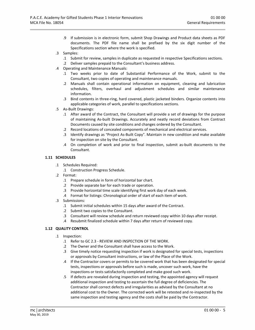
P.A.C.E. Academy for Gifted Students Phase 1 Interior Renovations 01 00 00 MCA File No. 18054 General Requirements
01 00 00 - 5
May 30, 2019
.9 If submission is in electronic form, submit Shop Drawings and Product data sheets as PDF documents. The PDF file name shall be prefixed by the six digit number of the Specifications section where the work is specified.
.3 Samples: .1 Submit for review, samples in duplicate as requested in respective Specifications sections. .2 Deliver samples prepaid to the Consultant=s business address.
.4 Operating and Maintenance Manuals: .1 Two weeks prior to date of Substantial Performance of the Work, submit to the
Consultant, two copies of operating and maintenance manuals. .2 Manuals shall contain operational information on equipment, cleaning and lubrication
schedules, filters, overhaul and adjustment schedules and similar maintenance information.
.3 Bind contents in three-ring, hard covered, plastic jacketed binders. Organize contents into applicable categories of work, parallel to specifications sections.
.5 As-Built Drawings: .1 After award of the Contract, the Consultant will provide a set of drawings for the purpose
of maintaining As-built Drawings. Accurately and neatly record deviations from Contract Documents caused by site conditions and changes ordered by the Consultant.
.2 Record locations of concealed components of mechanical and electrical services.
.3 Identify drawings as AProject As-Built Copy@. Maintain in new condition and make available for inspection on site by the Consultant.
.4 On completion of work and prior to final inspection, submit as-built documents to the Consultant.
1.11 SCHEDULES
.1 Schedules Required: .1 Construction Progress Schedule.
.2 Format: .1 Prepare schedule in form of horizontal bar chart. .2 Provide separate bar for each trade or operation. .3 Provide horizontal time scale identifying first work day of each week. .4 Format for listings: Chronological order of start of each item of work.
.3 Submissions: .1 Submit initial schedules within 15 days after award of the Contract. .2 Submit two copies to the Consultant. .3 Consultant will review schedule and return reviewed copy within 10 days after receipt. .4 Resubmit finalized schedule within 7 days after return of reviewed copy.
1.12 QUALITY CONTROL
.1 Inspection: .1 Refer to GC 2.3 - REVIEW AND INSPECTION OF THE WORK. .2 The Owner and the Consultant shall have access to the Work. .3 Give timely notice requesting inspection if work is designated for special tests, inspections
or approvals by Consultant instructions, or law of the Place of the Work. .4 If the Contractor covers or permits to be covered work that has been designated for special
tests, inspections or approvals before such is made, uncover such work, have the inspections or tests satisfactorily completed and make good such work.
.5 If defects are revealed during inspection and testing, the appointed agency will request additional inspection and testing to ascertain the full degree of deficiencies. The Contractor shall correct defects and irregularities as advised by the Consultant at no additional cost to the Owner. The corrected work will be retested and re-inspected by the same inspection and testing agency and the costs shall be paid by the Contractor.

01 00 00 P.A.C.E. Academy for Gifted Students Phase 1 Interior Renovations General Requirements MCA File No. 18054
01 00 00 - 6 May 30, 2019
.2 Independent Inspection Agencies: .1 Independent Inspection and Testing Agencies will be engaged by the Owner for the
purpose of inspecting and testing portions of the Work. Costs shall be paid from the cash allowance as specified in this section.
.2 Provide equipment required for executing inspection and testing by appointed agencies. .3 Report Distribution:
.1 Submit 1 copy of inspection and test reports to the Owner.
.2 Submit 2 copies of inspection and test reports to the Consultant within 10 Working Days of the date of the subject inspection or test.
.3 Provide 2 copies of inspection and test reports to the Contractor.
.4 Provide 1 copy of inspection and test reports to Subconsultants affected.
.5 Provide 1 copy of inspection and test report to Subcontractor of work being inspected or tested.
.6 Provide 1 copy of inspection and test reports to Municipal Building Department.
1.13 CONSTRUCTION FACILITIES AND TEMPORARY CONTROLS
.1 Installation and Removal: .1 Provide construction facilities and temporary controls in order to execute the Work
expeditiously. .2 Remove from site all such work after use.
.2 Dust Tight Screens: .1 Provide dust tight screens or partitions to localize dust generating activities, and for
protection of workers, finished areas of Work and public. .2 Maintain and relocate protection until such work is complete.
.3 Protection of Building Finishes and Equipment: .1 Provide protection for finished and partially finished building finishes and equipment
during performance of the Work. .2 Provide necessary screens, covers, and hoarding as required. .3 Be responsible for damage incurred due to lack of or improper protection.
.4 Site Storage and Loading: .1 Refer to GC 3.11 - USE OF THE WORK .2 Confine the Work and operations of employees to limits indicated by the Contract
Documents. Do not unreasonably encumber premises with Products. .3 Do not load or permit to be loaded any part of the Work with a weight or force that will
endanger the Work. .5 Sanitary Facilities:
.1 Provide sufficient sanitary facilities for workers in accordance with requirements of local health authorities.
.2 Maintain in clean condition and keep stocked with supplies. .6 Water Supply:
.1 The existing building water service may be used to supply potable water for construction use.
.7 Temporary Heating: .1 Provide temporary heating required during construction period, including attendance,
maintenance and fuel. .2 Construction heaters used inside building must be vented to outside or be non-flameless
type. Solid fuel salamanders not permitted. .3 Maintain temperatures of minimum 10C in areas where construction is in progress, unless
indicated otherwise in specifications. .4 Ventilate heated areas and keep building free of exhaust or combustion gases. .5 Permanent heating system of building, or portions thereof, may be used when available.
Be responsible for damage thereto.

P.A.C.E. Academy for Gifted Students Phase 1 Interior Renovations 01 00 00 MCA File No. 18054 General Requirements
01 00 00 - 7
May 30, 2019
.8 Temporary Power and Light: .1 The existing building electrical service may be used during construction for temporary
lighting and operation of power tools, to maximum supply allowed by the existing electrical service.
.2 Provide and maintain temporary lighting throughout the Project. Level of illumination on all floors and stairs shall not be less than 162 lx (15 foot candles).
.9 Temporary Computer: .1 Provide and maintain on site a computer with E-mail capability.
.10 Equipment, Tool, and Materials Storage: .1 Provide and maintain, in clean and orderly condition, lockable weatherproof sheds for
storage of tools, equipment and materials. .2 Locate materials not required to be stored in weatherproof sheds on site in manner to
cause least interference with work activities. .11 Project Cleanliness and Property Protection:
.1 Maintain the Work in tidy condition, free from accumulation of waste products and debris.
.2 Remove waste material and debris from the Work and deposit in waste container or remove from site at end of each working day.
.3 Clean interior areas prior to start of finish work, maintain areas free of dust and other contaminants during finishing operations.
.4 Protect surrounding private and public property from damage during performance of the Work.
.5 Keep municipal roadways and sidewalks adjacent to the site clean and free of mud, dust, dirt, and debris.
.12 Fire Protection: .1 Open rubbish and the burning of rubbish are not permitted on site. .2 The appropriate clauses of the Ontario Building Code relating to fire protection shall be
strictly followed. .13 Temporary Use of New Permanent Service and Equipment: Do not use any new permanent
service or equipment without the written approval of the Owner. .14 Construction Parking: Parking will be permitted on site provided it does not disrupt the
performance of the Work nor interfere with access to the building by occupants and visitors. Coordinate requirements with the Owner=s representative. Parking is not permitted on the street at any time.
1.14 MATERIAL AND EQUIPMENT
.1 Product and Material Quality: .1 Refer to GC 3.8 - LABOUR AND PRODUCTS. .2 Products, materials, equipment and articles (referred to as Products throughout
specifications) incorporated in the Work shall be new, not damaged or defective, and of best quality (compatible with specifications) for purpose intended. If requested, furnish evidence as to type, source and quality of Products provided.
.3 Defective Products will be rejected, regardless of previous inspections. Inspection does not relieve responsibility, but is precaution against oversight or error. Remove and replace defective Products at own expense and be responsible for delays and expenses caused by rejection.
.4 Should any dispute arise as to quality or fitness of Products, the decision rests strictly with the Consultant based upon requirements of the Contract Documents.
.2 Availability and Substitutions: .1 Provide products as specified in these specifications or as identified on Drawings. Where
several proprietary Products are specified for an item, and they are not identified as alternatives, then any one of the several is acceptable. Refer to Alternates article above for procedures to incorporate specified alternatives into the Work.

01 00 00 P.A.C.E. Academy for Gifted Students Phase 1 Interior Renovations General Requirements MCA File No. 18054
01 00 00 - 8 May 30, 2019
.2 During the bid period and prior to the Contract signing alternates may be proposed by the Contractor. Refer to Document 00 21 00 - Instructions to Bidders: Product/System Options for procedures to incorporate proposed alternates into the Work.
.3 Except as provided in subparagraphs .4 and .5, no substitutions to specified Products will be accepted after the Contract has been signed.
.4 Immediately upon signing the Contract, review Product delivery requirements and anticipate foreseeable supply delays for any items. If delays in supply of Products are foreseeable, or if it is found that specified materials have become unavailable for incorporating into the Work, notify the Consultant of such, in order that substitutions or other remedial action may be authorized in ample time to prevent delays in the performance of the Work.
.5 In the event of failure to notify the Consultant at the commencement of the Work and should it subsequently appear that the Work may be delayed for such reason, the Consultant reserves the right to substitute more readily available products of similar character, at no increase in the Contract Price. In every case the Contractor shall be responsible for changes in space requirements regarding substituted Products.
.3 Transportation, Storage, Handling and Protection: .1 Pay transportation costs of Products required in the performance of the Work. .2 Handle and store products in manner to prevent damage, adulteration, deterioration and
soiling and in accordance with manufacturer=s instructions when applicable. .3 Store packaged or bundled Products in original and undamaged condition with
manufacturer=s seals and labels intact. .4 Store Products subject to damage from weather in weatherproof enclosures.
.4 Manufacturer=s Instructions: .1 Unless otherwise indicated in Specifications install or erect Products in accordance with
manufacturer=s instructions. Do not rely on labels or enclosures provided with Products. Obtain written instructions directly from manufacturers.
.2 Notify the Consultant in writing, of conflicts between the specifications and manufacturer=s instructions, so that the Consultant may establish the course of action.
.3 Improper installation or erection of Products, due to failure in complying with these requirements, authorizes the Consultant to require removal and reinstallation at no increase in Contract Price.
.5 Manufacturer=s Inspection and Certification: .1 Whenever indicated on the Drawings, in the Specifications, or in manufacturers= or
Suppliers= written instructions, manufacturers’ representatives shall inspect work that incorporates their materials or Products.
.2 When manufacturer inspection is required, the manufacturer=s representative shall be on site at the start of work that incorporates the manufacturer=s Products, in order to verify that the correct Products are installed and proper installation procedures are followed.
.3 When the work incorporating the manufacturer=s Products is completed, the manufacturer=s representative shall carry out a final inspection in order to verify that the work as installed complies with the Contract Documents and the approved Shop Drawings.
.4 After the manufacturer=s final inspection, the manufacturer shall prepare a letter of certification of inspection. This letter shall be submitted to the Contractor for inclusion with the documentation required in the Project Closeout article below.
.5 The letter of certification of inspection shall be dated and include the following: .1 Name of Project and the Consultant=s Project number. .2 Name of Subcontractor. .3 Name of manufacturer=s contact person, and on-site representative if different, with
telephone and fax numbers. .4 Dates of on-site inspections, including start-up and final inspection.

P.A.C.E. Academy for Gifted Students Phase 1 Interior Renovations 01 00 00 MCA File No. 18054 General Requirements
01 00 00 - 9
May 30, 2019
.5 Certification that the work as installed incorporates the correct materials and Products and satisfies the requirements of the Contract Documents and approved Shop Drawings.
.6 Workmanship and Coordination: .1 Workmanship shall be best quality, executed by workers experienced and skilled in the
respective duties for which they are employed. Immediately notify the Consultant if required work is such as to make it impractical to produce required results.
.2 Do not employ any unfit person or anyone unskilled in their required duties.
.3 Decisions as to quality or fitness of workmanship in cases of dispute rest solely with the Consultant, whose decision is final.
.4 Ensure cooperation of workers in laying out work. Maintain efficient and continuous supervision. Coordinate placement of openings, sleeve, and accessories.
.7 Concealment: .1 In finished areas, conceal pipes, ducts and wiring in floors, walls and ceilings, except where
indicated otherwise. .2 Before installation, inform the Consultant if there is a contradictory situation. Install as
directed by the Consultant. .8 Fastenings:
.1 All fastenings shall be permanent, of same metal, or compatible with any metals with which they are in contact, of adequate size and spacing, to ensure permanent anchorage against load or shear.
.2 Exposed fastenings shall be evenly spaced, neatly laid out, and shall not mar surfaces of prefinished materials.
.3 No ram setting or similar techniques will be permitted, without prior written approval of the Consultant.
1.15 PROJECT CLOSEOUT
.1 Final Cleaning: .1 Refer to GC 3.13 - CLEANUP .2 When the Work is Substantially Performed, remove surplus products, tools construction
machinery and equipment not required for performance of the remaining work. .3 Remove waste materials and debris from site at regularly scheduled times or dispose of as
directed by the Consultant. Do not burn waste materials on site, unless approved by the Consultant.
.4 Leave the Work broom clean before inspection process commences.
.5 Clean and polish glass, mirrors, hardware, wall tile, stainless steel, chrome, porcelain enamel, baked enamel, plastic laminate, mechanical and electrical fixtures. Replace broken, scratched or disfigured glass.
.6 Remove stains, spots, marks and dirt from decorative work, electrical and mechanical fixtures, furniture fitments, and walls
.7 Vacuum clean and dust building interiors, behind grilles, louvres and screens.
.8 Wax, seal, or prepare floor finishes, as recommended by the manufacturer.
.9 Broom clean and power wash exterior walks, steps and surfaces that have been soiled during the Work.
.10 Remove dirt and other disfigurations from exterior surfaces. .2 Systems Demonstrations:
.1 Prior to final inspection, demonstrate operation of each system to the Owner and the Consultant.
.2 Instruct personnel in operation, adjustment, and maintenance of equipment and systems, using provided operation and maintenance data as basis for instruction.

01 00 00 P.A.C.E. Academy for Gifted Students Phase 1 Interior Renovations General Requirements MCA File No. 18054
01 00 00 - 10 May 30, 2019
.3 Documents: .1 Collect reviewed submittals and assemble documents executed by Subcontractors,
suppliers, and manufacturers. .2 Submit material prior to final Application for Payment. .3 Submit operation and maintenance data, record (as-built) drawings, and manufacturers=
letters of certification of inspection. .4 Provide warranties and bonds fully executed and notarized. .5 Execute transition of Performance and Labour and Materials Payment Bond to warranty
period requirements. .6 Submit a final statement of accounting giving total adjusted Contract Price, previous
payments, and monies remaining due. .7 The Consultant will issue a final change order reflecting approved adjustments to the
Contract Price not previously made. .4 Spare Parts and Maintenance Materials:
.1 Provide spare parts and maintenance and extra materials in quantities specified in individual specification sections.
.2 Provide items of same manufacture and quality as items in the Work.
.3 Deliver to Project site in location as directed; place and store.
.4 Submit inventory list to the Consultant. Include approved lists in Maintenance Manual specified in Submittals article above.
.5 Inspection and Takeover Procedures: .1 Comply with the provisions of OAA/OGCA Document No. 100, Take-Over Procedures,
except as modified in these specifications. .2 Prior to application for certificate of Substantial Performance, carefully inspect the Work
and ensure it is complete, that major and minor construction deficiencies are complete, defects are corrected and building is clean and in condition for occupancy. Notify the Consultant, in writing, of satisfactory completion of the work and request an inspection.
.3 During the Consultant=s inspection, a list of deficiencies and defects will be tabulated. Correct same.
.4 When the Consultant considers deficiencies and defects have been corrected and it appears requirements of the Contract have been performed, make application for certificate of Substantial Performance. Refer to General Conditions Article GC 5.4 - SUBSTANTIAL PERFORMANCE OF THE WORK for specifics to the application.
PART 2 PRODUCTS
Not Used.
PART 3 EXECUTION
Not Used.
END OF SECTION

P.A.C.E. Academy for Gifted Students Phase 1 Interior Renovations 02 41 19 MCA File No. 18054 Selective Demolition
02 41 19 - 1
May 30, 2019
PART 1 GENERAL
1.01 SECTION INCLUDES
.1 Demolition and removal of portions of interior non-load bearing walls and partitions.
.2 Demolition and removal of portions of interior load bearing walls and structure.
.3 Removal of surface finishes, suspended ceilings, millwork, fitments and doors
.4 Removal of designated substances and hazardous materials.
1.02 RELATED SECTIONS
.1 Section 01 00 00 - General Requirements.
1.03 STANDARDS
.1 Comply with O. Reg. 213/91, Regulations for Construction Projects, made under the Occupational Health and Safety Act.
1.04 ASBESTOS
.1 Demolition of spray or trowel applied asbestos can be hazardous to health. Should material resembling spray or trowel-applied asbestos be encountered, stop work and notify the Consultant immediately.
.2 Do not proceed until written instructions have been received from the Consultant.
.3 Refer to The Designated Substance Survey in Section 00 31 00.
1.05 PROTECTION
.1 Prevent movement, settlement, or other damage to adjacent structures, utilities, and parts of building to remain in place. Provide bracing and shoring as required. Shoring shall be designed by a Professional Engineer licensed to practise in the Province of Ontario.
.2 Keep noise, dust, and inconvenience to occupants to minimum.
.3 Protect building systems, services and equipment. Protect existing finished surfaces to remain in areas of the Work.
.4 During stages of the Work when portions of the building may be occupied by the Owner, maintain protected egress and access to exits at all times.
.5 Provide temporary barriers, security devices, dust screens, covers, railings, supports and other protection as required.
.6 Provide dust screens to limit spread of dust generated during demolition operations.
.7 Take precautions to support affected construction to remain during demolition of adjacent elements.
.8 Demolition Dust Control: .1 Designate truck loading points to avoid trucks tracking demolition debris off site. Loading
points shall be on a gravel base or paved area. Maintain in a clean condition. .2 Clean all vehicles leaving the site of dust from demolition debris. Include the washing of
tires and sweeping or washing of exteriors and tailgates by a designated labourer. Maintain a daily log of each truck leaving the site.
.3 Tarp all vehicles leaving the site which are loaded with demolition debris. .9 Waste Auditing and Reduction:
.1 Demolition and construction waste shall be audited and source-separated as required under the Environmental Protection Act. Materials that shall be source-separated include corrugated cardboard, brick, concrete, steel, wood, and gypsum board.
.2 Comply with O.Reg. 102/94, Waste Audits and Waste Reduction Workplans and O.Reg. 103/94, Industrial, Commercial and Institutional Source Separation Programs.
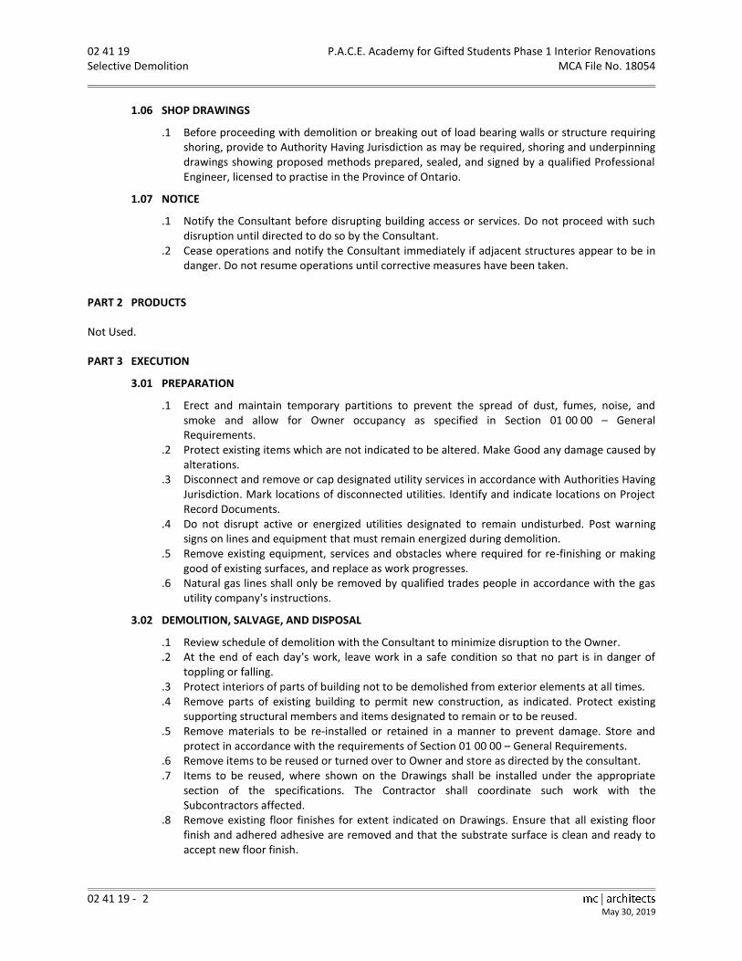
02 41 19 P.A.C.E. Academy for Gifted Students Phase 1 Interior Renovations Selective Demolition MCA File No. 18054
02 41 19 - 2 May 30, 2019
1.06 SHOP DRAWINGS
.1 Before proceeding with demolition or breaking out of load bearing walls or structure requiring shoring, provide to Authority Having Jurisdiction as may be required, shoring and underpinning drawings showing proposed methods prepared, sealed, and signed by a qualified Professional Engineer, licensed to practise in the Province of Ontario.
1.07 NOTICE
.1 Notify the Consultant before disrupting building access or services. Do not proceed with such disruption until directed to do so by the Consultant.
.2 Cease operations and notify the Consultant immediately if adjacent structures appear to be in danger. Do not resume operations until corrective measures have been taken.
PART 2 PRODUCTS
Not Used.
PART 3 EXECUTION
3.01 PREPARATION
.1 Erect and maintain temporary partitions to prevent the spread of dust, fumes, noise, and smoke and allow for Owner occupancy as specified in Section 01 00 00 – General Requirements.
.2 Protect existing items which are not indicated to be altered. Make Good any damage caused by alterations.
.3 Disconnect and remove or cap designated utility services in accordance with Authorities Having Jurisdiction. Mark locations of disconnected utilities. Identify and indicate locations on Project Record Documents.
.4 Do not disrupt active or energized utilities designated to remain undisturbed. Post warning signs on lines and equipment that must remain energized during demolition.
.5 Remove existing equipment, services and obstacles where required for re-finishing or making good of existing surfaces, and replace as work progresses.
.6 Natural gas lines shall only be removed by qualified trades people in accordance with the gas utility company=s instructions.
3.02 DEMOLITION, SALVAGE, AND DISPOSAL
.1 Review schedule of demolition with the Consultant to minimize disruption to the Owner.
.2 At the end of each day=s work, leave work in a safe condition so that no part is in danger of toppling or falling.
.3 Protect interiors of parts of building not to be demolished from exterior elements at all times.
.4 Remove parts of existing building to permit new construction, as indicated. Protect existing supporting structural members and items designated to remain or to be reused.
.5 Remove materials to be re-installed or retained in a manner to prevent damage. Store and protect in accordance with the requirements of Section 01 00 00 – General Requirements.
.6 Remove items to be reused or turned over to Owner and store as directed by the consultant.
.7 Items to be reused, where shown on the Drawings shall be installed under the appropriate section of the specifications. The Contractor shall coordinate such work with the Subcontractors affected.
.8 Remove existing floor finishes for extent indicated on Drawings. Ensure that all existing floor finish and adhered adhesive are removed and that the substrate surface is clean and ready to accept new floor finish.

P.A.C.E. Academy for Gifted Students Phase 1 Interior Renovations 02 41 19 MCA File No. 18054 Selective Demolition
02 41 19 - 3
May 30, 2019
.9 Remove and dispose of contaminated or dangerous materials in accordance with Ministry of the Environment regulations and local by-laws. Do not burn materials on site.
.10 Dispose of removed materials, except where specified otherwise, in accordance with the Authority Having Jurisdiction. Except where noted otherwise, immediately remove demolished materials from the site. Upon completion of work leave areas of work in clean condition.
3.03 HAZARDOUS AND DESIGNATED SUBSTANCES
.1 Refer to the Designated Substance Survey Report bound with document 00 31 00 - Information Available to Bidders for an inventory of the location of known hazardous and asbestos-containing materials.
.2 The Contractor and all Subcontractors shall review the Designated Substance Survey Report prior to commencing work.
.3 The Contractor shall post a copy of the Designated Substance Survey Report in the workplace.
.4 The Contractor shall coordinate work involving asbestos and asbestos removal with the Owner=s Representative.
.5 Upon locating unexpected asbestos-containing materials during the Work, immediately cease work in the areas and contact the consultant. Do not proceed with work until directed to do so by the Consultant.
.6 Comply with all regulations relating to asbestos. The removal and disposal of asbestos shall be in accordance with the Regulation Respecting Asbestos on Construction Projects and in Buildings and Repair Operations made under the Occupational Health and Safety Act.
END OF SECTION

P.A.C.E. Academy for Gifted Students Phase 1 Interior Renovations 03 30 00 MCA File No. 18054 Cast-in-Place Concrete
mc architects 03 30 00 - 1 May 30, 2019
PART 1 GENERAL
1.01 SECTION INCLUDES
.1 Cast-in-place concrete.
1.02 RELATED SECTIONS
.1 Section 01 00 00 - General Requirements.
.2 Section 03 35 00 - Concrete Floor Finishing.
1.03 REFERENCES
.1 ASTM-C109-91, Test Method for Compressive Strength of Hydraulic Cement Mortars (Using 2 in. Or 50 mm Cube Specimens).
.2 ASTM-C309-93, Specification for Liquid Membrane-Forming Compounds for Curing Concrete.
.3 CAN/CSA-A5-93, Portland Cement.
.4 CAN/CSA-A23.1-M90, Concrete Materials and Methods of Concrete Construction.
.5 CAN/CSA-A23.2-M90, Methods of Test for Concrete.
.6 CAN3-A23.3-M84, Design of Concrete Structures for Buildings.
.7 CAN3-A266.1-M78, Air-Entraining Admixtures for Concrete.
.8 CAN3-A266.2-M78, Chemical Admixtures for Concrete.
PART 2 PRODUCTS
2.01 MATERIALS
.1 Concrete: .1 Portland Cement: to CAN/CSA-A5. .2 Water: to CAN/CSA-A23.1. .3 Aggregates: to CAN/CSA-A23.1. Coarse aggregate shall be normal density. .4 Air Entraining Admixture: to CAN3-A266.1. .5 Chemical Admixtures: to CAN3-A266.2. Consultant will review use of accelerating or set
retarding admixtures prior to cold and hot weather placing. .6 Curing Compound: to CAN/CSA-A23.1, white.
.2 Concrete Mixes: .1 Interior Slabs:
.1 Normal density concrete
.2 Class of Exposure: N
.3 Cement: Type 10
.4 Min. Compressive Strength: 25MPa at 28 days
.5 Max. Water/Cement ratio: 0.55
.6 Max. Size Aggregate: 20mm
.7 Slump at time and point of discharge 50mm to 100mm
PART 3 EXECUTION
3.01 PREPARATION FOR CONCRETE PLACEMENT
.1 Obtain Consultant=s approval before placing concrete. Provide 24 hours’ notice prior to placing of concrete.
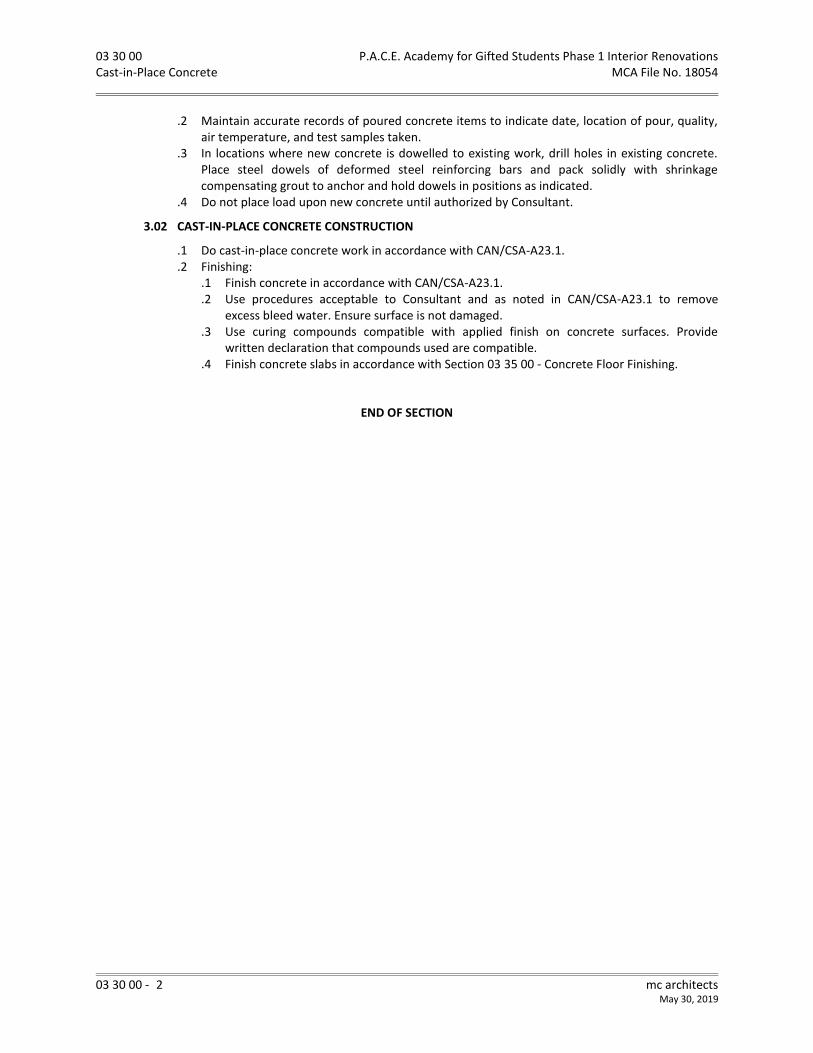
03 30 00 P.A.C.E. Academy for Gifted Students Phase 1 Interior Renovations Cast-in-Place Concrete MCA File No. 18054
03 30 00 - 2 mc architects May 30, 2019
.2 Maintain accurate records of poured concrete items to indicate date, location of pour, quality, air temperature, and test samples taken.
.3 In locations where new concrete is dowelled to existing work, drill holes in existing concrete. Place steel dowels of deformed steel reinforcing bars and pack solidly with shrinkage compensating grout to anchor and hold dowels in positions as indicated.
.4 Do not place load upon new concrete until authorized by Consultant.
3.02 CAST-IN-PLACE CONCRETE CONSTRUCTION
.1 Do cast-in-place concrete work in accordance with CAN/CSA-A23.1.
.2 Finishing: .1 Finish concrete in accordance with CAN/CSA-A23.1. .2 Use procedures acceptable to Consultant and as noted in CAN/CSA-A23.1 to remove
excess bleed water. Ensure surface is not damaged. .3 Use curing compounds compatible with applied finish on concrete surfaces. Provide
written declaration that compounds used are compatible. .4 Finish concrete slabs in accordance with Section 03 35 00 - Concrete Floor Finishing.
END OF SECTION

P.A.C.E. Academy for Gifted Students Phase 1 Interior Renovations 03 35 00 MCA File No. 18054 Concrete Floor Finishing
03 35 00 - 1
May 30, 2019
PART 1 GENERAL
1.01 SECTION INCLUDES
.1 Finishing concrete floor surfaces.
1.02 RELATED SECTIONS
.1 Section 01 00 00 - General Requirements.
.2 Section 03 30 00 - Cast-in-Place Concrete.
.3 Section 09 65 19 – Resilient Tile Flooring
1.03 REFERENCES
.1 ACI-302.1R-96,Guide for Concrete Floor and Slab Construction.
.2 ASTM-C171-97a, Sheet Materials for Curing Concrete.
.3 ASTM-C309-98a, Standard Specification for Liquid Membrane-Forming Compounds for Curing Concrete.
.4 ASTM-E1155M-96, Standard Test Method for Determining FF.
.5 CSA-A23.1-09, Concrete Materials and Methods of Concrete Construction.
.6 CSA-A23.2-14, Test Methods and Standard Practices for Concrete.
1.04 QUALITY ASSURANCE
.1 Conform to CSA-A23.1, CSA-A23.2, and ACI 302.1R.
1.05 QUALIFICATIONS
.1 Concrete Finishes Company specializing in commercial floor finishing with a minimum of five years documented experience, approved by the Consultant.
1.06 WARRANTY
.1 Provide a warranty for the work of this section in accordance with the General Conditions but for a period of three years.
.2 The warranty shall cover defects in concrete floor finishing due to faults in workmanship or materials provided in this section.
PART 2 PRODUCTS
2.01 MATERIALS
.1 Water: clean, potable and not detrimental to quality of concrete.
.2 Concrete Materials: Conform to Sections 03 10 00 - Concrete Forming, Section 03 20 00 - Concrete Reinforcing, and Section 03 30 00 - Cast-in-Place Concrete. Air content of concrete shall not exceed 3%.
.3 Concrete Sealer (SLC): water-based concrete densifier and chemical hardener. W.R. Meadows of Canada: Liqui-Hard Ultra.
PART 3 EXECUTION
3.01 EXAMINATION
.1 Verify that substrate surfaces are ready to receive work and elevations are as indicated on Drawings and as instructed by the finish flooring manufacturer.
.2 Beginning of installation shall mean acceptance of substrate and site conditions.

03 35 00 P.A.C.E. Academy for Gifted Students Phase 1 Interior Renovations Concrete Floor Finishing MCA File No. 18054
03 35 00 - 2 May 30, 2019
3.02 FINISHING CONCRETE FLOORS
.1 Finish concrete to CSA-A23.1 and CSA-A23.2.
.2 When concrete is placed, strike off or rod surface with a straight edge. Darby or bull float the surface to smooth and level the concrete.
.3 When the concrete has hardened enough to leave only slight footprints on the surface, float the surface with metal floats and power finishing machines and bring surface to a true elevation. Do not over float. Avoid bringing water and fines to the surface.
.4 Concrete Floors for Applied Thin-set Ceramic Tile Finish: .1 After floating, allow bleed water or sheen to disappear. .2 Steel trowel the surface by means of power and hand trowels. .3 Do not bring water and fines to the surface by over trowelling. .4 Surface shall have a fine even textured steel finish. Do not leave any hard smooth polished
or burnished surface areas. .5 Cure by the moist curing or sealed surface methods only.
.5 Concrete Floors for Applied Resilient Flooring Finish: .1 After floating, allow bleed water or sheen to disappear. .2 Steel trowel the surface by means of power and hand trowels. .3 Do not bring water and fines to the surface by over trowelling. .4 Allow slight interval for concrete to harden further and repeat trowelling operation. .5 Leave the surface with a smooth, level, extremely fine textured but not burnished finish. .6 Cure by any of the curing methods specified below. Ensure that any curing and sealing
compounds used are compatible with the resilient flooring adhesive .6 Sprinkling of dry cement or dry cement and sand mixture over concrete surfaces is not
acceptable.
3.03 CURING
.1 Cure concrete in accordance with CSA-A23.1 and CSA-CSA-A23.2.
.2 Moist Curing Method: .1 Cover the concrete with burlap or canvas coverings. .2 Keep the surface continuously wet by sprinkling or fog spray. .3 Concrete shall be kept moist for a minimum of seven consecutive days when normal
Portland cement is used, and for a minimum of three consecutive days when high early strength Portland cement is used.
.3 Sealed Surface Curing Method: .1 Cover the concrete with waterproof paper or polyethylene sheets. Lap all joints and tape. .2 Coverings shall be sufficiently heavy to be resistant to tearing and puncturing. .3 Coverings shall be kept in place for a minimum of seven consecutive days when normal
Portland cement is used, and for a minimum of three consecutive days when high early strength Portland cement is used.
.4 Liquid Applied Curing Compound Method: .1 Apply liquid curing compounds in strict accordance with the manufacturer=s instructions. .2 Ensure that curing compounds are compatible with applied floor finish adhesives.
.5 After curing and when concrete is dry, seal control joints and joints at junction with vertical surfaces with sealing compound.
.6 Concrete Sealer Application: .1 Ensure concrete surface is clean and free of standing water. Remove all material that may
prevent sealer adhesion. .2 Prime concrete surface as recommended by the concrete sealer manufacturer. .3 Apply concrete sealer at a uniform coverage by spray or roller application as
recommended by the concrete sealer manufacturer.

P.A.C.E. Academy for Gifted Students Phase 1 Interior Renovations 03 35 00 MCA File No. 18054 Concrete Floor Finishing
03 35 00 - 3
May 30, 2019
.4 Apply second coat of concrete sealer, as recommended by the manufacturer, within 24 hours of first coat application.
3.04 TOLERANCES
.1 Exposed High Wear Resistance Surface Dense Trowelled: 6mm in 3000mm.
.2 Exposed Smooth Non-slip Surface Trowelled and Broomed: 8mm in 3000mm.
.3 For porcelain tile, resilient sheet and resilient tile flooring level concrete slab to achieve a tolerance of 7mm in 3000mm
.4 Correct defects in the floor only by grinding or removal and replacement of the defective slabs. Areas requiring corrective work will be identified by the Consultant. Re-measure corrected areas. Costs of corrective work shall be borne by the Contractor.
3.05 PROTECTION
.1 Protect finished installation in accordance with the requirements of Section 01 00 00 – General Requirements.
END OF SECTION

P.A.C.E. Academy for Gifted Students Phase 1 Interior Renovations 04 20 00 MCA File No. 18054 Masonry
04 20 00 - 1
May 30, 2019
PART 1 GENERAL
1.01 SECTION INCLUDES
.1 Procedures for unit masonry work.
.2 Procedures for incorporating products to be built into unit masonry.
.3 Mortar for unit masonry.
.4 Masonry accessories, reinforcement, and connectors.
.5 Concrete unit masonry.
.6 Clay unit masonry
1.02 PRODUCTS INSTALLED BUT NOT SUPPLIED UNDER THIS SECTION
.1 Division 5: Supply of bearing plates, built-in anchors, and loose steel lintels.
.2 Section 08 11 00 - Steel Doors and Frames: Supply of hollow metal door frames for installation in masonry walls and partitions.
1.03 RELATED SECTIONS
.1 Division 1 - General Requirements.
.2 Section 05 12 00 - Structural Steel.
.3 Section 07 21 13 - Board Insulation.
.4 Section 07 27 00 - Air Barriers.
.5 Section 07 84 00 - Fire Stopping and Smoke Seals.
.6 Section 07 92 00 - Sealants: Sealants and caulking procedures.
.7 Section 08 11 00 - Steel Doors and Frames: Supply of hollow metal frames.
.8 Section 09 91 00 - Painting.
1.04 REFERENCES
.1 ASTM-A153/A153M-09, Standard Specification for Zinc Coating (Hot-Dip) on Iron and Steel Hardware.
.2 ASTM-C207-06(2011), Standard Specification for Hydrated Lime for Masonry Purposes.
.3 BIA, Technical Notes on Brick Construction No. 20, Cleaning Brick Masonry, November 1990.
.4 CSA-A23.1-09, Concrete Materials and Methods of Concrete Construction.
.5 CAN/CSA-A82-06, Fired Masonry Brick Made From Clay or Shale.
.6 CAN/CSA-A165 Series - 04 (R2009), CSA Standards on Concrete Masonry Units.
.7 CAN/CSA-A179-04 (R2009), Mortar and Grout for Unit Masonry.
.8 CAN/CSA-A370-14, Connectors for Masonry.
.9 CAN/CSA-A371-04 (R2009), Masonry Construction for Buildings.
.10 CAN/CSA-A3001-13, Cementitious Materials for Use in Concrete.
.11 CAN/CSA-A3002-13, Masonry and Mortar Cement.
.12 CAN/CSA-G30.18-09, Billet-Steel Bars for Concrete Reinforcement.
.13 CSA-S304.1-04, Design of Masonry Structures.
1.05 QUALITY ASSURANCE
.1 Masonry work shall be carried out by experienced masons under the continuous supervision of a competent foreman with a minimum of 5 years’ experience with work of similar size and complexity.
1.06 DELIVERY, STORAGE AND HANDLING
.1 Deliver materials to job site in dry condition.
.2 Keep materials dry until use except where wetting of bricks is specified.
.3 Store under waterproof cover on pallets or plank platforms held off ground by means of plank or timber skids.

04 20 00 P.A.C.E. Academy for Gifted Students Phase 1 Interior Renovations Masonry MCA File No. 18054
04 20 00 - 2 May 30, 2019
1.07 ENVIRONMENTAL REQUIREMENTS
.1 Hot Weather Requirements: Protect freshly laid masonry from drying too rapidly, by means of waterproof, non-staining coverings.
.2 Protect masonry and other work from marking and other damage. Protect completed work from mortar droppings. Use non-staining coverings.
1.08 QUALITY ASSURANCE
.1 Mortar prepared on-site based on proportion specifications: .1 Prior to the commencement of masonry work prepare on-site, under the supervision of the
inspection and testing company, mortar mixes for each mortar type specified. .2 The inspection and testing company will sample and test the mortar mixes to determine a
site aggregate/cement ratio Control Value for each mortar type. .3 Once Site Control Values are established these will form the basis of acceptance for all
subsequent Sample Ratio Tests conducted during the course of the work. .2 Mortar prepared off-site based on property specifications:
.1 Prior to the commencement of masonry work the inspection and testing company will sample and perform laboratory tests for each mortar type prepared off-site to verify compliance with the specifications.
.2 Testing shall consist of the determination of: .1 Aggregate/cement ratio. .2 Water retention. .3 Compressive strength. .4 Air content.
.3 Once acceptable values are established these will form the basis of acceptance for tests conducted during the course of the work.
PART 2 PRODUCTS
2.01 MATERIALS
.1 Mortar Materials: to CAN/CSA-A179. .1 Use the same brands of materials and source of aggregate for the entire project. .2 Portland Cement: Type GU, in accordance with CSA-A3001. .3 Masonry Cement: in accordance with CSA-A3002. .4 Hydrated Lime: Type S, in accordance with ASTM-C207. .5 Sand: in accordance with CSA-A179. .6 Water: potable and in accordance with CSA-A179. Water shall not contain acids, alkalis,
oils, and organic material. .2 Masonry Grout: Refer to Structural Drawings for masonry grout specifications. .3 Masonry Accessories:
.1 Horizontal Control Joint Filler: purpose-made elastomer for minimum compression of 25% of uncompressed size. .1 Emseal Corporation: Greyflex. .2 Tremco Commercial Sealants & Waterproofing: illmod 600.
.2 Vertical Control Joint Filler: preformed expanding elastomer for minimum compression of 25% of uncompressed size. .1 Emseal Corporation: Greyflex. .2 Tremco Commercial Sealants & Waterproofing: illmod 600.
.3 Compressible Joint Filler at Penetrations and Top of Masonry Partitions: .1 AD Fire Protection Systems Inc.: A/D Firebarrier Mineral Wool Firestopping Insulation. .2 Roxul Inc.: RXL Safe Fire Stop Batt.

P.A.C.E. Academy for Gifted Students Phase 1 Interior Renovations 04 20 00 MCA File No. 18054 Masonry
04 20 00 - 3
May 30, 2019
.4 Masonry Reinforcement and Connectors: .1 Bar Reinforcement: to CAN/CSA-A371 and CAN/CSA-G30.18. .2 Wire Joint Reinforcement - Single Wythe Walls: to CAN/CSA-A371, ladder type, 4.76mm
diameter wire, size to suit wall thickness. .1 Blok-Lok Limited: BL-10 Ladder Reinforcement. .2 Dur-O-Wal: DA3200 Single Wythe Ladur.
.3 Wire Joint Reinforcement - Cavity Walls: to CAN/CSA-A371, ladder type, 4.76mm diameter wire, size to suit wall thickness. Blok-Lok Limited: BL-42 Ladder Reinforcement.
.4 Corrosion Protection for Wire Joint Reinforcement: galvanized to ASTM-A153/A153M. .1 Exterior Wall: Hot dip galvanized, Class B2, 458g/m2 minimum coating. .2 Interior Wall: Mill galvanized.
.5 Cavity Wall Insulation Fasteners: .1 Blok-Lok Limited: Plastic wedge shaped, purpose made to wedge between masonry
reinforcing and cavity wall insulation. Wedge-Lok. .2 Fero Corporation: Polyethylene, purpose made to fit over connector and secure
insulation in place. Fero Insulation Support.
2.02 MORTAR MIXES
.1 Except where specified otherwise, the basis of acceptance for mortar prepared on-site shall be the proportion specifications in CAN/CSA-A179.
.2 The basis of acceptance for mortar prepared off-site shall be the property specifications in CAN/CSA-A179.
.3 Mortar for Exterior Masonry Above Grade: .1 Loadbearing: Type S. .2 Non-loadbearing: Type N.
.4 Mortar for Interior Masonry: .1 Loadbearing: Type S. .2 Non-loadbearing: Type N.
.5 The following apply regardless of the mortar types and uses specified above: .1 Mortar for grouted reinforced masonry: Type S. .2 Mortar for pointing: Type N.
.6 Pointing Mortar: Prehydrate pointing mortar by mixing ingredients dry, then mix again adding just enough water to produce damp unworkable mix that will retain its form when pressed into ball. Allow to stand for not less than 1 hour nor more than 2 hours then remix with sufficient water to produce mortar of proper consistency for pointing.
2.03 CONCRETE MASONRY UNITS
.1 Standard Light Weight Concrete Masonry Units: to CAN/CSA-A165. .1 Use at all above grade interior walls and partitions unless otherwise indicated or specified. .2 Hollow unit classification: H/15/C/M. .3 Solid unit classification: S/15/C/M. .4 Slag aggregate. .5 Size: modular, nominal 200mm by 400mm. .6 Special shapes: provide bull-nosed units for exposed corners. Provide purpose-made
shapes for lintels and bond beams. Provide additional special shapes as indicated. .2 Standard Normal Weight Concrete Masonry Units: to CAN/CSA-A165.
.1 Use at exterior walls and all loadbearing walls.
.2 Hollow unit classification: H/15/A/M; H/20/A/M units where indicated on Structural Drawings.
.3 Solid unit classification: S/15/A/M; S/20/A/M units where indicated on Structural Drawings.
.4 Size: modular, nominal 200mm by 400mm.

04 20 00 P.A.C.E. Academy for Gifted Students Phase 1 Interior Renovations Masonry MCA File No. 18054
04 20 00 - 4 May 30, 2019
.5 Special shapes: provide bull-nosed units for exposed corners. Provide purpose-made shapes for lintels and bond beams. Provide additional special shapes as indicated.
.3 Concrete Brick: to CAN/CSA-A165. .1 Type: II. .2 Size: Metric modular.
2.04 CLAY MASONRY UNITS
.1 Face Brick: Burned clay brick, to CAN/CSA-A82. .1 Grade: EG (Exterior Grade). .2 Type: X. .3 Manufacturer: Brampton Brick .4 Size: Metric Modular .5 Colour and texture: xxxxxx
PART 3 EXECUTION
3.01 INSTALLATION - GENERAL
.1 Do masonry work in accordance with CAN/CSA-A370, CAN/CSA-A371, and CSA-S304.1 except where specified otherwise.
.2 Do masonry mortar work in accordance with CAN/CSA-A179 except where specified otherwise.
.3 Build masonry plumb, level, and true to line, with vertical joints in alignment.
.4 Layout coursing and bond to achieve correct coursing heights, and continuity of bond above and below openings, with minimum of cutting.
.5 Reinforcement: .1 Accurately place reinforcement, support, and secure against displacement as indicated on
structural drawings and in accordance with CAN/CSA-A371. .2 Prior to placing grout, obtain Consultant's approval of placement of reinforcement and
connectors. .3 Do additional reinforcement of masonry as indicated. .4 Locations of Joint Reinforcement:
.1 Concrete masonry unit wythe in cavity walls.
.2 Single wythe masonry walls and partitions. .5 Install joint reinforcement horizontally at 400mm on centre vertical spacing, unless
indicated otherwise. .6 Place additional reinforcement extending 600mm beyond jambs in courses 200mm,
400mm and 800mm above and below wall openings. .7 Lap joint reinforcement 300mm at splices.
.6 Reinforce and grout loadbearing masonry walls as shown on the Structural Drawings.
.7 Bonding and Tying: .1 Bond walls of two or more wythes using metal connectors in accordance with the OBC,
CSA-S304.1, CAN/CSA-A371 and as indicated. .2 Tie masonry veneer to backing in accordance with OBC, CSA-S304.1, CAN/CSA-A371 and as
indicated. .8 Reinforced Lintels and Bond Beams:
.1 Reinforce masonry lintels and bond beams as indicated on Structural Drawings. Make joints in lintels and bond beams to match adjacent walls.
.2 Place and grout reinforcement in accordance with CAN/CSA-A371, and the Structural Drawings.
.9 Extend walls and partitions to underside of deck or slab unless noted otherwise on Drawings.
.10 Construct portions of walls and partitions above doors, screens and other openings to match adjacent wall and partition construction unless noted otherwise on Drawings.

P.A.C.E. Academy for Gifted Students Phase 1 Interior Renovations 04 20 00 MCA File No. 18054 Masonry
04 20 00 - 5
May 30, 2019
.11 Masonry Accessories: .1 Install continuous control joint fillers in control joints at locations indicated. .2 Install compressible joint filler at the top of masonry partitions that are not fire
separations. Refer to Section 07 84 00 - Fire Stopping and Smoke Seals for joint treatment at fire separations.
.12 Refer to Structural Drawings for load-bearing masonry structural requirements.
3.02 INSTALLATION - CONCRETE UNIT MASONRY
.1 Concrete Masonry Units: .1 Bond: running bond unless indicated otherwise .2 Coursing height: 200mm for one unit and one joint. .3 Jointing: concave.
.2 Concrete Masonry Unit Lintels: .1 Install reinforced concrete masonry unit lintels over openings in masonry where steel or
reinforced concrete lintels are not indicated. .2 End bearing: as indicated on Drawings but not less than 200mm.
.3 All exposed jambs, corners, sills, ledges, and caps of concrete masonry units shall be bullnosed finish.
.4 At walls to receive ceramic tile or rubber base, first block course shall have 90 corners with top edge of block ground round to match bullnose block above.
.5 Cores of hollow concrete masonry units within 400mm of wall openings shall be filled solid with grout.
3.03 INSTALLATION CLAY - UNIT MASONRY
.1 Bond: to match existing.
.2 Coursing Height: to match existing.
.3 Jointing: concave.
.4 Clean unglazed clay unit masonry as work progresses.
3.04 CONSTRUCTION
.1 Exposed Masonry: Remove chipped, cracked, and otherwise damaged units in exposed masonry and replace with undamaged units.
.2 Jointing: .1 Allow joints to set just enough to remove excess water, then tool with round jointer to
provide smooth, true to line, compressed, uniformly concave joints unless other jointing is indicated or specified.
.2 Strike flush all joints concealed in walls and joints in walls to receive plaster, tile, insulation, or other applied material except paint or similar thin finish coating.
.3 Wall surfaces and joint treatment for concealed portions of walls above ceilings and behind wall mounted fitments shall match exposed surfaces.
.3 Cutting: .1 Cut out for electrical switches, outlet boxes, and other recessed or built-in objects. .2 Make cuts straight, clean, and free from uneven edges.
.4 Building-In: .1 Prevent displacement of built-in items during construction. Check for plumb, location and
alignment frequently, as work progresses. .2 Build-in hollow metal frames. Brace door jambs to maintain plumb. Fill spaces between
jambs and masonry with mortar. Set frame anchors as specified in Section 08 11 00 - Steel Doors and Frames.
.3 Where structural steel members penetrate masonry walls fill-in spaces with neatly cut pieces of masonry units set in event mortar beds with tooled joints. Do not use rubble or broken pieces and mortar combinations as in-fill.

04 20 00 P.A.C.E. Academy for Gifted Students Phase 1 Interior Renovations Masonry MCA File No. 18054
04 20 00 - 6 May 30, 2019
.5 Wetting of Bricks: .1 Except in cold weather, wet bricks having an initial rate of absorption exceeding
1g/minute/1000mm5, wet to uniform degree of saturation, 3 to 24 hours before laying, and do not lay until surface dry.
.2 Wet tops of walls built of bricks qualifying for wetting, when recommencing work on such walls.
.6 Support of Loads: .1 Use grout to CAN/CSA-A179 where grout is used instead of solid units. Cells with
reinforcement shall be grouted. Grout masonry in accordance with CSA-S304.1 and as indicated on Structural Drawings.
.2 Install building paper below voids to be filled with concrete or grout; keep paper 25mm back from faces of units.
.7 Provision for Movement: .1 Leave 25mm space between top of non-load bearing walls and partitions and structural
elements. Do not use wedges. .2 Build masonry to tie in with stabilizers, with provision for vertical movement.
.8 Loose Steel Lintels: Install loose steel lintels supplied by Division 5. Centre over opening width.
.9 Bearing Plates and Anchors: Install loose steel bearing plates and anchors supplied by Division 5.
.10 Control Joints for Non-loadbearing Masonry Walls: .1 Construct continuous full height control joints as indicated. .2 Fill void at control joint with 20MPa concrete grout to form continuous key. .3 Locate interior wall control joints at a maximum spacing of 6000mm, and where
non-loadbearing walls meet loadbearing walls. .11 Site Tolerances: Tolerances in notes to Clause 5.3 of CAN/CSA-A371 apply. .12 Lateral Support and Anchorage:
.1 Do lateral support and anchorage in accordance with CSA-S304.1 and as indicated.
.2 Lateral Support Anchors (for attachment to structural steel): Blok-Lok, Flex-o-Lok. .13 Control Joints: Terminate reinforcement 25mm short of each side of control joints unless
otherwise indicated.
3.05 FIELD BENDING AND TOUCH-UP
.1 Do not field bend reinforcement and connectors except where indicated or authorized by the Consultant.
.2 When field bending is authorized, bend without heat, applying a slow and steady pressure.
.3 Replace bars and connectors which develop cracks or splits.
.4 Touch up damaged and cut ends of epoxy coated or galvanized reinforcement steel and connectors with compatible finish to provide continuous coating.
3.06 RE-INSTALLATION
.1 Cut openings in existing work as indicated.
.2 Openings in walls to be approved by Consultant.
.3 Make Good existing work. Use materials to match existing.
3.07 CLEANING
.1 Standard Masonry Units: Allow mortar droppings on masonry to partially dry then remove by means of trowel, followed by rubbing lightly with small piece of block and finally by brushing.
.2 Protect windows, sills, doors, trim and other work, and clean brick masonry as follows: .1 Remove large particles with wood paddles without damaging surface. Saturate
masonry with clean water and flush off loose mortar and dirt. .2 Scrub with solution of 25mL trisodium phosphate and 25mL household detergent
dissolved in 1 L of clean water using stiff fibre brushes, then clean off immediately

P.A.C.E. Academy for Gifted Students Phase 1 Interior Renovations 04 20 00 MCA File No. 18054 Masonry
04 20 00 - 7
May 30, 2019
with clean water using hose. Alternatively, use proprietary compound recommended by brick masonry manufacturer in accordance with manufacturer's directions.
.3 Repeat cleaning process as often as necessary to remove mortar and other stains.
.4 Use acid solution treatment for difficult to clean masonry as described in BIA Technical Note No. 20.
3.08 FIELD QUALITY CONTROL
.1 Inspection and testing of masonry work will be carried out by an inspection and testing company designated by the Consultant.
.2 Cost of masonry inspection and testing will be paid from the cash allowance specified in Section 01 00 00 – General Requirements.
.3 Masonry Mortar: As masonry work progresses, the inspection and testing company will test and report on mortar properties as follows: .1 Mortar prepared in accordance with proportion specifications: Aggregate/Cement ratio. .2 Mortar prepared in accordance with property specifications: compressive strength. .3 Provide six 50mm by 50mm by 50mm mortar samples taken at random for each test when
requested by inspection and testing company.
END OF SECTION

P.A.C.E. Academy for Gifted Students Phase 1 Interior Renovations 05 52 00 MCA File No. 18054 Metal Railings for Stairs
05 52 00 - 1
May 30, 2019
PART 1 GENERAL
1.01 SECTION INCLUDES
.1 Wall mounted stainless steel handrails.
1.02 RELATED SECTIONS
.1 Section 01 00 00 - General Requirements.
.2 Section 09 91 00 - Painting.
1.03 REFERENCES
.1 ASTM-A269-96e1, Standard Specification for Seamless and Welded Austenitic Stainless Steel Tubing for General Service.
.2 ASTM-A307-94, Standard Specification for Carbon Steel Bolts and Studs, 60,000 psi Tensile.
.3 CAN/CGSB-1.40-97, Anticorrosive Structural Steel Alkyd Primer.
.4 CAN/CGSB-1.181-92, Ready-Mixed Organic Zinc-Rich Coating.
.5 CSA-S16-09, Design of Steel Structures.
.6 CSA-W47.1-97, Certification of Companies for Fusion Welding of Steel Structures.
.7 CSA-W59-M1989, Welded Steel Construction (Metal Arc Welding).
1.04 DESIGN REQUIREMENTS AND QUALITY ASSURANCE
.1 Detail and fabricate railings to NAAMM Metal Stairs Manual.
.2 Qualification of Welders: .1 Welding of stair railings shall be performed by fabricators certified under CSA-W47.1.
.3 Conform to requirements of authorities having jurisdiction.
.4 Conform to requirements of CSA-S16.
1.05 SHOP DRAWINGS
.1 Submit Shop Drawings in accordance with Section 01 00 00 – General Requirements
.2 Indicate construction details, sizes of steel sections, thickness of steel sheet, and connection and handrail details.
.3 Submit Shop Drawings bearing the seal and signature of a qualified Professional Engineer licensed to practise in the Province of Ontario.
PART 2 PRODUCTS
2.01 MATERIALS
.1 Steel Plate: to CAN/CSA-G40.21, Grade 260W.
.2 Stainless Steel Tubing: to ASTM-A269, type 304 seamless, welded with AISI No. 4 finish.
.3 Welding Materials: to CSA-W59.
.4 Bolts: to ASTM-A307.
2.02 FABRICATION
.1 Fabricate to NAAMM-AMP510.
.2 Weld connections where possible, otherwise bolt connections. Countersink exposed fastenings, cut off bolts flush with nuts. Make exposed connections of same material, colour and finish as base material on which they occur.
.3 All welded areas on stainless steel shall be ground and finished to blend with adjacent areas for an invisible seam.
.4 Shop fabricate railings in sections as large and complete as practicable.
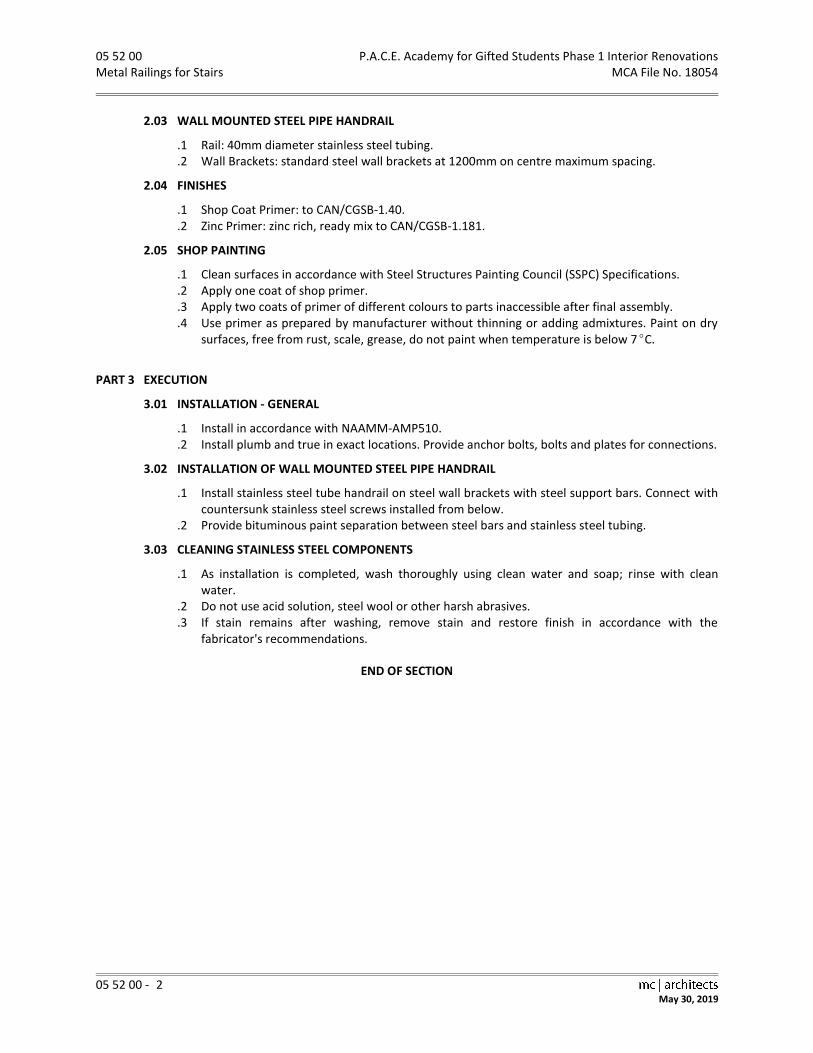
05 52 00 P.A.C.E. Academy for Gifted Students Phase 1 Interior Renovations Metal Railings for Stairs MCA File No. 18054
05 52 00 - 2 May 30, 2019
2.03 WALL MOUNTED STEEL PIPE HANDRAIL
.1 Rail: 40mm diameter stainless steel tubing.
.2 Wall Brackets: standard steel wall brackets at 1200mm on centre maximum spacing.
2.04 FINISHES
.1 Shop Coat Primer: to CAN/CGSB-1.40.
.2 Zinc Primer: zinc rich, ready mix to CAN/CGSB-1.181.
2.05 SHOP PAINTING
.1 Clean surfaces in accordance with Steel Structures Painting Council (SSPC) Specifications.
.2 Apply one coat of shop primer.
.3 Apply two coats of primer of different colours to parts inaccessible after final assembly.
.4 Use primer as prepared by manufacturer without thinning or adding admixtures. Paint on dry surfaces, free from rust, scale, grease, do not paint when temperature is below 7C.
PART 3 EXECUTION
3.01 INSTALLATION - GENERAL
.1 Install in accordance with NAAMM-AMP510.
.2 Install plumb and true in exact locations. Provide anchor bolts, bolts and plates for connections.
3.02 INSTALLATION OF WALL MOUNTED STEEL PIPE HANDRAIL
.1 Install stainless steel tube handrail on steel wall brackets with steel support bars. Connect with countersunk stainless steel screws installed from below.
.2 Provide bituminous paint separation between steel bars and stainless steel tubing.
3.03 CLEANING STAINLESS STEEL COMPONENTS
.1 As installation is completed, wash thoroughly using clean water and soap; rinse with clean water.
.2 Do not use acid solution, steel wool or other harsh abrasives.
.3 If stain remains after washing, remove stain and restore finish in accordance with the fabricator=s recommendations.
END OF SECTION

P.A.C.E. Academy for Gifted Students Phase 1 Interior Renovations 06 10 00 MCA File No. 18054 Rough Carpentry
06 10 00 - 1
May 30, 2019
PART 1 GENERAL
1.01 SECTION INCLUDES
.1 Wood grounds, nailers, blocking in walls.
.2 Wood furring.
1.02 RELATED SECTIONS
.1 Section 01 00 00 - General Requirements.
.2 Section 06 20 00 - Finish Carpentry.
1.03 REFERENCES
.1 AWMAC/WI–NAAWS, North American Architectural Woodwork Standards, version 3.1, 2017.
.2 CSA-B111-1974, Wire Nails, Spikes and Staples.
.3 CAN/CSA-O141-05, Softwood Lumber.
.4 CSA-O151-09, Canadian Softwood Plywood.
.5 NLGA, Standard Grading Rules for Canadian Lumber, 2014.
1.04 QUALITY ASSURANCE
.1 Lumber Identification: by grade stamp of an agency certified by Canadian Lumber Standards Accreditation Board.
.2 Plywood Identification: by grade mark in accordance with applicable CSA standards.
1.05 STORAGE, DELIVERY AND HANDLING
.1 Store clear of ground or other bearing surfaces on blocking to prevent damage from moisture absorption.
.2 Store on site for minimum amount of time prior to incorporating into building.
.3 Tarp or cover exposed materials for protection from elements.
PART 2 PRODUCTS
2.01 LUMBER MATERIAL
.1 Lumber: unless specified otherwise, softwood, S4S, moisture content 12% or less in accordance with following standards: .1 CAN/CSA-O141. .2 NLGA Standard Grading Rules for Canadian Lumber.
.2 Furring, Blocking, Nailing Strips, Grounds, Rough Bucks: .1 S2S is acceptable. .2 Board sizes: "Standard" or better grade. .3 Dimension sizes: "Standard" light framing or better grade.
2.02 PANEL MATERIALS
.1 Canadian Softwood Plywood (CSP): to CSA-O151, standard construction.
2.03 ACCESSORIES
.1 Nails, Spikes and Staples: to CSA-B111.
.2 Proprietary Fasteners: toggle bolts, expansion shields and lag bolts, screws and lead or inorganic fibre plugs, recommended for purpose by manufacturer.
2.04 FINISHES
.1 Galvanizing: to CAN/CSA-G164.
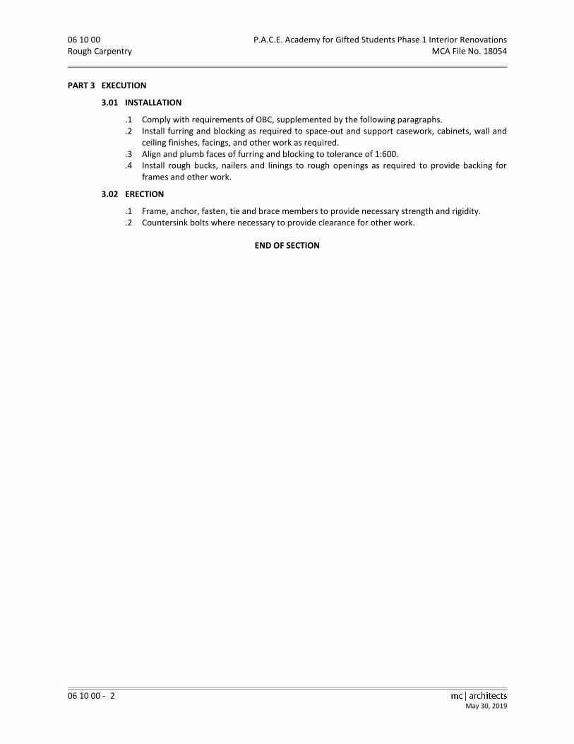
06 10 00 P.A.C.E. Academy for Gifted Students Phase 1 Interior Renovations Rough Carpentry MCA File No. 18054
06 10 00 - 2 May 30, 2019
PART 3 EXECUTION
3.01 INSTALLATION
.1 Comply with requirements of OBC, supplemented by the following paragraphs.
.2 Install furring and blocking as required to space-out and support casework, cabinets, wall and ceiling finishes, facings, and other work as required.
.3 Align and plumb faces of furring and blocking to tolerance of 1:600.
.4 Install rough bucks, nailers and linings to rough openings as required to provide backing for frames and other work.
3.02 ERECTION
.1 Frame, anchor, fasten, tie and brace members to provide necessary strength and rigidity.
.2 Countersink bolts where necessary to provide clearance for other work.
END OF SECTION

P.A.C.E. Academy for Gifted Students Phase 1 Interior Renovations 06 20 00 MCA File No. 18054 Finish Carpentry
06 20 00 - 1
May 30, 2019
PART 1 GENERAL
1.01 SECTION INCLUDES
.1 Installation of shop fabricated casework.
.2 Site fabricated fitments.
.3 Installation of steel doors.
.4 Installation of door hardware and miscellaneous hardware.
1.02 RELATED SECTIONS
.1 Section 01 00 00 - General Requirements.
.2 Section 06 41 05 - Plastic Laminates.
.3 Section 06 41 10 - Architectural Woodwork.
.4 Section 06 41 93 - Cabinet and Miscellaneous Hardware.
.5 Section 08 11 00 - Steel Doors and Frames.
.6 Section 08 71 00 - Door Hardware.
.7 Section 09 91 00 - Painting.
1.03 PRODUCTS INSTALLED BUT NOT SUPPLIED UNDER THIS SECTION
.1 Shop Fabricated Fitments: casework and millwork supplied under Section 06 41 10 - Architectural Woodwork.
.2 Steel Doors: supplied under Section 08 11 00 - Steel Doors and Frames.
.3 Door Hardware: supplied under Section 08 71 00 - Door Hardware.
.4 Miscellaneous Hardware: supplied under Section 06 41 93 - Cabinet and Miscellaneous Hardware.
1.04 REFERENCES
.1 ANSI-A208.1-1993, Particleboard, Mat-Formed Wood.
.2 AWMAC/WI–NAAWS, North American Architectural Woodwork Standards, version 3.1, 2017.
.3 CAN/CGSB-1.175-97, Polyurethane Interior Coating.
.4 CAN/CGSB-11.3-M87, Hardboard.
.5 CLA, Canadian Hardwood Flooring Grading Rules, 2002.
.6 CSA-B35.4-1972, Wood Screws.
.7 CSA-B111-1974, Wire Nails, Spikes and Staples.
.8 CAN/CSA-G164-M92, Hot Dip Galvanizing of Irregularly Shaped Articles.
.9 CSA-O115-M1982, Hardwood and Decorative Plywood.
.10 CSA-O121-08, Douglas Fir Plywood.
.11 CAN/CSA-O132.2 Series-90 (R1996), Wood Flush Doors.
.12 CAN/CSA-O141-05, Softwood Lumber.
.13 CSA-O151-09, Canadian Softwood Plywood.
.14 CSA-O153-M1980, Poplar Plywood.
.15 CAN3-O188.1-M78, Interior Mat-Formed Wood Particleboard.
.16 NHLA, Rules for the Measurement and Inspection of Hardwood and Cypress, January 2015.
.17 NLGA, Standard Grading Rules for Canadian Lumber, 2014.
1.05 SAMPLES
.1 Submit samples in accordance with Section 01 00 00 – General Requirements.
.2 Samples: sample size shall be 300mm by 300mm or 300mm long unless specified otherwise of each wood species which is to receive finishing at the job site; finished samples of each panel material which has a factory applied finish; PVC edge strip.

06 20 00 P.A.C.E. Academy for Gifted Students Phase 1 Interior Renovations Finish Carpentry MCA File No. 18054
06 20 00 - 2 May 30, 2019
1.06 SHOP DRAWINGS
.1 Submit Shop Drawings in accordance with Section 01 00 00 – General Requirements.
.2 Indicate details of construction, profiles, jointing, fastening and other related details.
.3 Indicate all materials, thicknesses, finishes and hardware.
1.07 PRODUCT, DELIVERY, STORAGE, AND HANDLING
.1 Protect materials against dampness during and after delivery.
.2 Store materials in ventilated areas, protected from extreme changes of temperature or humidity.
.3 Wood door delivery, storage and handling shall be in accordance with Section 2 and 9, of AWMAC/WI–NAAWS.
.4 Delivered materials, which are damaged in any way will be rejected by the Consultant and shall be removed from the site and replaced with acceptable materials.
PART 2 PRODUCTS
2.01 LUMBER MATERIAL
.1 Softwood Lumber: unless specified otherwise, S4S, moisture content of 7% or less in accordance with the following standards: .1 CAN/CSA–O141. .2 NLGA Standard Grading Rules for Canadian Lumber. .3 AWMAC/WI–NAAWS custom grade, moisture content as specified.
.2 Machine stress-rated lumber is acceptable for all purposes.
.3 Hardwood Lumber: Select White Hard Maple moisture content of 7% or less in accordance with the following standards: .1 National Hardwood Lumber Association (NHLA). .2 AWMAC/WI–NAAWS custom grade, moisture content as specified.
2.02 PANEL MATERIAL
.1 Douglas Fir Plywood (DFP): to CSA-O121, standard construction.
.2 Canadian Softwood Plywood (CSP): to CSA-O151, standard construction.
.3 Hardwood Plywood: to CSA-O115. Face veneer: Plain Sliced, bookmatched, Select White Hard Maple. Core as specified.
.4 Poplar Plywood (PP): to CSA-O153, standard construction.
.5 Particleboard: medium density, M-3 grade to ANSI-A208.1.
.6 Hardboard: to CAN/CGSB-11.3.
.7 Melamine Panels: .1 Melamine overlay, thermofused under heat and pressure to particleboard core. Colour will
be selected by the Consultant. Texture: [ ]. .2 Overlay shall be bonded to both faces where exposed on two sides, and when the panel
material requires a finished surface on one side only, the reverse side shall be overlaid with a plain buff balancing sheet.
.3 Edge finishing: matching 3.2mm PVC edge strip, colour and pattern through full thickness of material.
2.03 ACCESSORIES
.1 Nails and Staples: to CSA-B111; galvanized to CAN/CSA-G164 for exterior work, interior humid areas and for treated lumber; plain finish elsewhere.
.2 Wood Screws: to CSA-B35.4 electroplated, type and size to suit application.
.3 Splines: metal.
.4 Adhesive: as recommended by material manufacturer.

P.A.C.E. Academy for Gifted Students Phase 1 Interior Renovations 06 20 00 MCA File No. 18054 Finish Carpentry
06 20 00 - 3
May 30, 2019
PART 3 EXECUTION
3.01 INSTALLATION
.1 Do finish carpentry in accordance with AWMAC/WI–NAAWS, except where specified otherwise.
.2 Scribe and cut as required, fit to abutting walls, and surfaces, fit properly into recesses and to accommodate piping, columns, fixtures, outlets, or other projecting, intersecting or penetrating objects.
.3 Form joints to conceal shrinkage.
.4 Install shop fabricated casework and millwork. Refer to Section 06 41 10 - Architectural Woodwork.
.5 Install site fabricated fitments as shown on Drawings.
.6 Install wood doors. Refer to Section 08 14 00 - Wood Doors.
.7 Install steel doors. Refer to Section 08 11 00 - Steel Doors and Frames.
.8 Install door hardware. Refer to Section 08 71 00 - Door Hardware.
.9 Install miscellaneous hardware. Refer to Section 06 41 93 - Cabinet and Miscellaneous Hardware.
3.02 CONSTRUCTION
.1 Fastening: .1 Position items of finished carpentry work accurately, level, plumb, true and fasten or
anchor securely. .2 Design and select fasteners to suit size and nature of components being joined. Use
proprietary devices as recommended by manufacturers. .3 Set finishing nails to receive filler. Where screws are used to secure members, countersink
screw in round cleanly cut hole and plug with wood plug to match material being secured. .4 Replace items of finish carpentry with damage to wood surfaces including hammer and
other bruises. .2 Shelving: Install shelving on ledgers or shelf brackets, as indicated.
3.03 SCHEDULE OF SITE FABRICATED FITMENTS
.1 Change Room Benches: .1 To AWMAC/WI–NAAWS for custom quality. .2 Fabricate and install as detailed. .3 Wood: Solid White Hard Maple.
END OF SECTION

P.A.C.E. Academy for Gifted Students Phase 1 Interior Renovations 06 41 05 MCA File No. 18054 Plastic Laminates
06 41 05 - 1
May 30, 2019
PART 1 GENERAL
1.01 SECTION INCLUDES
.1 Plastic laminate finish for postformed counters.
.2 Plastic laminate finish for flatwork.
1.02 RELATED SECTIONS
.1 Section 01 00 00 - General Requirements.
.2 Section 06 20 00 - Finish Carpentry.
.3 Section 06 41 10 - Architectural Woodwork.
.4 Section 07 92 00 - Sealants
1.03 REFERENCES
.1 CAN/CGSB-71.20-M88, Adhesive, Contact, Brushable.
.2 CAN3-A172-M79 (R1996), High Pressure Paper Base, Decorative Laminates.
1.04 SAMPLES
.1 Submit samples in accordance with Section 01 00 00 – General Requirements.
.2 Submit samples of joints, edging, cutouts and postformed profiles.
.3 Provide maintenance data for laminate work for incorporation into manual specified in Section 01 00 00 – General Requirements.
1.05 STORAGE AND PROTECTION
.1 Maintain relative humidity between 25 and 60% at 22C during storage and installation.
1.06 WARRANTY
.1 Submit a warranty for plastic laminate work in accordance with the General Conditions, but for a period of three years.
.2 The warranty shall cover materials, workmanship and delamination.
PART 2 PRODUCTS
2.01 MATERIALS
.1 Laminated Plastic for Flatwork: to CAN3-A172, general purpose grade, type 1, thickness of 1.6mm.
.2 Laminated Plastic for Postforming Work: to CAN3-A172, postforming grade, type 2 thickness of 1.25mm.
.3 Plastic laminate shall have a matte finish in standard colours selected by the Consultant from the product line of one of the following manufacturers: .1 Arborite. .2 Formica. .3 Nevamar. .4 Pionite. .5 Wilsonart.
.4 Laminated Plastic Backing Sheet: general purpose grade S not less than 0.5mm thick or same thickness and colour as face laminate.
.5 Laminated Plastic Adhesive: contact adhesive to CAN/CGSB-71.20.
.6 Sealer: water resistant sealer or glue acceptable to laminate manufacturer.
.7 Sealants: Refer to Section 07 92 00 - Sealants.
.8 Draw Bolts and Splines: as recommended by fabricator.

06 41 05 P.A.C.E. Academy for Gifted Students Phase 1 Interior Renovations Plastic Laminates MCA File No. 18054
06 41 05 - 2 May 30, 2019
2.02 FABRICATION
.1 Comply with CAN3-A172, Appendix 'A'.
.2 Obtain governing dimensions before fabricating items which are to accommodate or abut appliances, equipment and other materials.
.3 Ensure adjacent parts of continuous laminate work match in colour and pattern.
.4 Veneer laminated plastic to core material in accordance with adhesive manufacturer's instructions. Ensure core and laminate profiles coincide to provide continuous support and bond over entire surface. Use continuous lengths up to 3000 mm. Keep joints 600 mm from sink cutouts.
.5 Form shaped profiles and bends as indicated, using postforming grade laminate to laminate manufacturer's instructions.
.6 Use straight self-edging laminate strip for flatwork to cover exposed edge of core material. Chamfer exposed edges uniformly at approximately 20 degrees. Do not mitre laminate edges.
.7 Apply laminate backing sheet to reverse side of core of plastic laminate work.
.8 Apply laminated plastic liner sheet where indicated.
PART 3 EXECUTION
3.01 INSTALLATION
.1 Install work plumb, true and square, neatly scribed to adjoining surfaces.
.2 Make allowances around perimeter where fixed objects pass through or project into laminated plastic work to permit normal movement without restriction.
.3 Use draw bolts and splines in countertop joints. Maximum spacing of 450 mm on centre, 75 mm from edge. Make flush hairline joints.
.4 Provide cutouts for inserts, grilles, appliances, outlet boxes and other penetrations. Round internal corners, chamfer edges and seal exposed core.
.5 At junction of laminated plastic counter back splash and adjacent wall finish, apply small bead of sealant.
.6 Apply laminated plastic to units for on-site laminating as indicated. Adhere laminated plastic over entire surface. Make corners with hairline joints. Use full sized laminate sheets. Make joints only where approved. Slightly bevel arrises.
.7 For site application, offset joints in plastic laminate facing from joints in core.
3.02 PROTECTION
.1 Cover finished laminated surfaces with heavy Kraft paper or place in cartons during shipment.
.2 Protect installed laminated surfaces by approved means. Do not remove protective coverings until immediately before final inspection.
END OF SECTION

P.A.C.E. Academy for Gifted Students Phase 1 Interior Renovations 06 41 10 MCA File No. 18054 Architectural Woodwork
06 41 10 - 1
May 30, 2019
PART 1 GENERAL
1.01 SECTION INCLUDES
.1 Shop fabricated fitments: casework and millwork.
1.02 RELATED SECTIONS
.1 Section 01 00 00 - General Requirements.
.2 Section 06 41 05 - Plastic Laminates.
.3 Section 06 20 00 - Finish Carpentry.
.4 Section 06 41 93 - Cabinet and Miscellaneous Hardware.
.5 Section 06 61 16 - Solid Polymer Panels and Counter Tops.
.6 Section 07 92 00 - Sealants.
.7 Section 08 71 00 - Door Hardware.
.8 Section 09 91 00 - Painting.
.9 Division 22 - Plumbing: Sink Installation.
.10 Division 26 - Electrical: Power outlets and valance lighting.
1.03 PRODUCTS INSTALLED BUT NOT SUPPLIED UNDER THIS SECTION
.1 Millwork hardware, supplied under Section 06 41 93 - Cabinet and Miscellaneous Hardware and Section 08 71 00 - Door Hardware.
.2 The architectural millwork Subcontractor shall include in his contract the cost to provide millwork hardware, as specified in Section 06 41 93 - Cabinet and Miscellaneous Hardware.
1.04 REFERENCES
.1 ANSI-A208.1-2009, Particleboard, Mat Formed Wood.
.2 ANSI-A208.2-1994, Medium Density Fibreboard for Interior Use.
.3 ASTM-A167-96, Standard Specification for Stainless and Heat-Resisting Chromium-Nickel Steel Plate, Sheet, and Strip.
.4 AWMAC/WI–NAAWS, North American Architectural Woodwork Standards, version 3.1, 2017.
.5 CAN/CGSB-11.3-M87, Hardboard.
.6 CAN3-A172-M79 (R1996), High Pressure Paper Base, Decorative Laminates.
.7 CSA-B111-1974, Wire Nails, Spikes and Staples.
.8 CAN/CSA-O141-05, Softwood Lumber.
.9 CAN3-O188.1-M78, Interior Mat-Formed Wood Particleboard.
.10 NHLA, Rules for the Measurement and Inspection of Hardwood and Cypress, January 2015.
.11 NLGA, Standard Grading Rules for Canadian Lumber, 2014.
1.05 SHOP DRAWINGS
.1 Submit Shop Drawings in accordance with Section 01 00 00 – General Requirements.
.2 Indicate details of construction, profiles, jointing, fastening and other related details.
.3 Indicate all materials, thicknesses, finishes and hardware.
.4 Indicate locations of all service outlets in casework, typical and special installation conditions, and all connections, attachments, anchorage and location of exposed fastenings.
1.06 SAMPLES
.1 Submit samples in accordance with Section 01 00 00 – General Requirements.
.2 Submit samples: sample size 300mm by 300mm of typical finished door panel.
.3 Submit 300mm by 300mm colour samples of each type of laminated plastic selected.
.4 Submit 300mm by 300mm samples of each type of melamine panel.
.5 Submit 300mm by 300mm samples of each type of solid wood and plywood used in exposed work with examples of finish.

06 41 10 P.A.C.E. Academy for Gifted Students Phase 1 Interior Renovations Architectural Woodwork MCA File No. 18054
06 41 10 - 2 May 30, 2019
1.07 QUALITY ASSURANCE
.1 The architectural woodwork Subcontractor shall be a member in good standing of the Architectural Woodwork Manufacturers Association of Canada (AWMAC).
.2 Architectural woodwork shall be manufactured and installed to the specified AWMAC/WI–NAAWS standards.
.3 Work which does not meet AWMAC/WI–NAAWS, as specified, shall be replaced by the architectural woodwork Subcontractor, at no additional cost to the Owner and to the satisfaction of the Consultant.
.4 Architectural woodwork shall be provided by one of the following companies: .1 Canadian Institutional Furniture Co. (CIF). .2 Personal Touch Woodcrafters Ltd. .3 Second Generation Furnishings Inc. .4 Top Millwork. .5 Hemmingwoods
1.08 DELIVERY, STORAGE, AND HANDLING
.1 Protect casework and millwork against dampness and damage during and after delivery.
.2 Store casework and millwork in ventilated areas, protected from extreme changes of temperature or humidity.
.3 Do not deliver casework and millwork units to site until storage areas are complete and conditions permit, to ensure no damage will occur while in storage.
1.09 WARRANTY
.1 Submit a warranty for architectural woodwork in accordance with the General Conditions, but for a period of three years.
.2 The warranty shall cover replacing and refinishing to make good any defects due to defective materials, faulty workmanship, and delamination, and shall certify that the architectural woodwork has been manufactured and installed in accordance with the standards incorporated in the AWMAC/WI–NAAWS.
PART 2 PRODUCTS
2.01 MATERIALS
.1 Softwood Lumber: unless specified otherwise, S4S, moisture content 7% or less in accordance with following standards: .1 CAN/CSA-O141. .2 NLGA Standard Grading Rules for Canadian Lumber. .3 AWMAC/WI–NAAWS custom grade, moisture content as specified.
.2 Machine stress-rated lumber is acceptable for all purposes.
.3 Hardwood Lumber: Select White Hard Maple moisture content 7% or less in accordance with following standards: .1 National Hardwood Lumber Association (NHLA). .2 AWMAC/WI–NAAWS custom [premium] grade, moisture content as specified.
.4 Particleboard: medium density M-3 grade to ANSI-208.1.
.5 Maple Plywood: to AWMAC/WI–NAAWS. G2S where both sides are exposed, G1S where only one side is exposed, Select White Hard Maple, plain sliced and bookmatched face veneer, Grade A, core as specified.
.6 Hardboard: to CAN/CGSB-11.3, Type 2-Tempered.
.7 Laminated Plastic: to CAN3-A172. Refer to Section 06 41 05 - Plastic Laminates for type and finish.
.8 Melamine Panels:

P.A.C.E. Academy for Gifted Students Phase 1 Interior Renovations 06 41 10 MCA File No. 18054 Architectural Woodwork
06 41 10 - 3
May 30, 2019
.1 Melamine overlay, thermofused under heat and pressure to medium density M-3 grade particleboard core.
.2 Overlay shall be bonded to both faces where exposed on two sides, and when panel material requires surface on one side only, reverse side shall be overlaid with a plain buff balancing sheet.
.3 Acceptable Products: .1 Egger: H1210 Grey Beige .2 Brookside Veneers: 2-298/00/xp12 Silver Grey Oak .3 Tafisa: T2013 Summertime Blues, Sommet Series, Viva texture .4 Panolam: Wedding Cake .5 Panval: 511 Hiteak
.9 Solid Core Wood Doors: Custom quality, particleboard core to AWMAC/WI–NAAWS, Section 9, thickness as shown on Drawings. Provide interior solid wood blocking at surface-mounted hardware locations and as shown on Drawings. .1 Select White Hard Maple grade, plain sliced and bookmatched face veneer and stile edges.
.10 Hardwood Edging: .1 All exposed edges shall be banded with 3mm hardwood edging. .2 Edging shall be multi-layered natural wood made from 0.6mm veneers laminated together
with PVA glue containing no hazardous ingredients and having no harmful effects on health or the environment.
.3 Final assembly of the edging shall be surface sanded to 180 grit and roughly sanded on the reverse side for good adhesion.
.4 The top layer of the edging shall have a continuous high quality veneer to match the plywood with minimal colour variation.
.5 All layers of the edging shall have asymmetrical finger joints.
.6 All edging shall be stored in a controlled humidified environment prior to application in order to provide proper adhesion.
.11 PVC Edging: 3.2mm thick, colour and pattern through full thickness of material to match panel finish, with rounded edges.
.12 Nails and Staples: to CSA-B111.
.13 Wood Screws: steel type and size to suit application.
.14 Splines: metal.
.15 Sealant: Refer to Section 07 92 00 - Sealants. Use aluminum coloured sealant at stainless steel locations.
.16 Millwork Hardware: Refer to Section 06 41 93 - Cabinet and Miscellaneous Hardware and Section 08 71 00 - Door Hardware.
.17 Grilles: .1 Sill grille: Price Industries, model No. LBPH Series, Type 25C, with 25mm border, type A
fastenings, B15 brushed aluminum finish, 200mm wide, refer to Drawings for length. .2 Foot grille: Price Industries, model No. LG250, type A fastenings, 2mm thick, B15 brushed
aluminum finish, 100mm high, refer to Drawings for length.
2.02 MANUFACTURED UNITS
.1 Casework: General. .1 This article covers all casework unless detailed or specified otherwise. .2 Fabricate casework to AWMAC/WI–NAAWS custom quality grade, unless specified
otherwise, and to details and sizes as indicated. .3 Furring, blocking, nailing strips, grounds and rough bucks and sleepers.
.1 S2S is acceptable.
.2 Board sizes: "Standard" or better grade.
.3 Dimension sizes: "Standard" light framing or better. .2 Case Bodies:

06 41 10 P.A.C.E. Academy for Gifted Students Phase 1 Interior Renovations Architectural Woodwork MCA File No. 18054
06 41 10 - 4 May 30, 2019
.1 Melamine panels, 19mm thick, particleboard core.
.2 PVC edging, colour to match melamine panels finish. .3 Backs: Melamine panels, 6mm thick, particleboard core. .4 Shelving:
.1 Melamine panels, particleboard core.
.2 For spans up to 810mm: 19mm melamine panels.
.3 For spans greater than 810mm and up to 1050mm: 25mm melamine panels.
.4 For spans greater than 1050mm: support with intermediate gable.
.5 PVC edging, colour to match shelving finish. .5 Drawers:
.1 Face: melamine panels, 19mm thick, particleboard core. PVC edging colour to match face finish
.2 Drawer Box - Front, back and sides: melamine panels 13mm thick, particleboard core, white colour. Melamine edging to match drawer box finish.
.3 Drawer Bottom: melamine panels, 6mm thick, particleboard core. .6 Casework Doors:
.1 Melamine panels, 19mm thick, particleboard core.
.2 PVC edging, colour to match door finish. .7 Closet Doors: Solid core wood doors with plastic laminate finish. Plastic laminate shall be as
specified in Section 06 41 05 - Plastic Laminates. .8 Counter Tops:
.1 Postformed: Laminated plastic on 19mm particleboard.
.2 Self-edge Flatwork: Laminated plastic on 19mm particleboard
.3 Refer to Section 06 41 05 for Plastic Laminates. .9 Set finish nails below finished surfaces. .10 Shop install cabinet hardware supplied by Section 06 41 93 - Cabinet and Miscellaneous
Hardware for doors, shelves and drawers. Recess shelf standards unless noted otherwise. .11 Shelving to cabinetwork shall be adjustable unless otherwise noted. .12 Provide cutouts for plumbing fixtures, inserts, appliances, outlet boxes and other fixtures. .13 Shop assemble work for delivery to site in size easily handled and to ensure passage through
building openings.
2.03 MULTI-PURPOSE ROOM BENCH
.1 Fabricate to AWMAC/WI–NAAWS for custom quality.
.2 Gables and Bottom: melamine panels, 19mm thick, colour as indicated. PVC edging, colour shall match panels.
.3 Top: .1 Top layer: 19mm particleboard. .2 Bottom layer: melamine panels, 19mm thick, colour to match gables and bottom. .3 Finish: Plastic Laminate. Refer to Section 06 41 05 – Plastic Laminates. .4 Edging: Solid Maple, size and configuration as detailed.
2.04 CLASSROOM CUBICLES
.1 Fabricate to AWMAC/WI–NAAWS for custom quality.
.2 Fabricate from 19mm melamine panels as indicated and detailed
.3 Provide two double coat hook per cubicle bay, supplied by Section 06 41 93 - Cabinet and Miscellaneous Hardware.
2.05 FINISHING
.1 White Hard Maple veneer fitments and solid trims shall be finished in accordance with Section 5 - Finishing of AWMAC/WI–NAAWS.
.2 Finish:

P.A.C.E. Academy for Gifted Students Phase 1 Interior Renovations 06 41 10 MCA File No. 18054 Architectural Woodwork
06 41 10 - 5
May 30, 2019
.1 Transparent clear finish: Post-Catalyzed Lacquer Finish System, Satin gloss finish.
.2 Semi-Transparent stain and varnish finish: Post-Catalyzed Lacquer Finish System, with vinyl washcoat and stain, stain colour will be selected by the Consultant, Satin gloss finish.
PART 3 EXECUTION
3.01 EXAMINATION
.1 Prior to fabricating the work of this section verify dimensions on site to minimize site cutting.
.2 Where appropriate incorporate extra material to allow for scribing to adjacent surfaces.
3.02 INSTALLATION
.1 Do architectural woodwork to AWMAC/WI–NAAWS, except where specified otherwise.
.2 Install prefinished millwork at locations shown on Drawings. Position accurately, level, plumb straight.
.3 Fasten and anchor millwork securely. Provide heavy duty fixture attachments for wall mounted cabinets.
.4 Use draw bolts in countertop joints.
.5 Scribe and cut as required to fit abutting walls and to fit properly into recesses and to accommodate piping, columns, fixtures, outlets or other projecting, intersecting or penetrating objects.
.6 At junction of plastic laminate counter back and side splash with adjacent wall finish, apply a small bead of sealant. Refer to Section 07 92 00 - Sealants.
.7 Apply bituminous coating over wood framing members in contact with masonry or cementitious construction.
.8 Install hardware for woodwork of this Section as specified in Section 06 41 93 - Cabinet and Miscellaneous Hardware and Section 08 71 00 - Door Hardware. Fit hardware accurately and securely in accordance with the hardware manufacturer's directions.
3.03 CLEANING
.1 Clean millwork and cabinet work, inside cupboards and drawers and all outside surfaces.
3.04 PROTECTION
.1 Protect millwork and cabinet work from damage until final inspection.
END OF SECTION

MCA File No. 18054 06 41 93 P.A.C.E. Academy for Gifted Students Phase 1 Interior Renovations Cabinet and Miscellaneous Hardware
06 41 93 - 1
May 30, 2019
PART 1 GENERAL
1.01 SECTION INCLUDES
.1 Hardware for custom fabricated millwork.
.2 Miscellaneous hardware.
1.02 RELATED SECTIONS
.1 Section 01 00 00 - General Requirements.
.2 Section 06 20 00 - Finish Carpentry.
.3 Section 06 41 10 - Architectural Woodwork.
.4 Section 08 71 00 - Door Hardware.
1.03 PRODUCTS SUPPLIED BUT NOT INSTALLED UNDER THIS SECTION
.1 Millwork Hardware: for installation under Section 06 41 10 - Architectural Woodwork.
.2 Miscellaneous Hardware: for installation under Section 06 20 00 - Finish Carpentry.
1.04 REFERENCE STANDARDS
.1 CAN/CGSB-69.17-M86, Bored and Preassembled Locks and Latches.
.2 CAN/CGSB-69.25-M90/ANSI/BHMA-A156.9-1982, Cabinet Hardware.
.3 CAN/CGSB-69.27-93/ANSI/BHMA-A156.11-1991, Cabinet Locks.
.4 CAN/CGSB-69.32-M90/ANSI/BHMA-A156.16-1981, Auxiliary Hardware.
1.05 SAMPLES
.1 Submit samples in accordance with Section 01 00 00 – General Requirements.
.2 Submit one sample of each piece of hardware.
1.06 HARDWARE SCHEDULE
.1 Submit cabinet and miscellaneous hardware schedule in accordance with Section 01 00 00 – General Requirements.
.2 Indicate specified hardware, including make, model, material, function, finish and other pertinent information.
1.07 MAINTENANCE DATA
.1 Provide maintenance data, parts list, and manufacturer's instructions for incorporation into manual specified in Section 01 00 00 – General Requirements.
.2 Brief maintenance staff regarding proper care, cleaning, and general maintenance.
1.08 DELIVERY AND STORAGE
.1 Store hardware in locked, clean and dry area.
.2 Package each item of hardware including fastenings, separately or in like groups of hardware, label each package as to item definition and location.
PART 2 PRODUCTS
2.01 HARDWARE ITEMS
.1 Use one manufacturer's Product for all similar items.
2.02 MILLWORK HARDWARE
.1 Cabinet Hardware: to CAN/CGSB-69.25.

06 41 93 P.A.C.E. Academy for Gifted Students Phase 1 Interior Renovations Cabinet and Miscellaneous Hardware MCA File No. 18054
06 41 93 - 2 May 30, 2019
.1 Hinges: 170 opening, self-closing, full overlay hinges, with factory-installed knock-on dowels. Wood screw fastening system will not be accepted. Acceptable Products: Blum or Salice.
.2 Hinge Plates: one piece plate with minimum 3mm height adjustment, install using pre-mounted system screws. Wood screw fastening system will not be accepted.
.3 Door Dampener: Blumotion 971A with Cruciform Base.
.4 Bumpers: polyurethane, 3mm high by 10mm diameter. Minimum 2 per door and drawer front.
.5 Pulls: 8mm diameter solid aluminum wire type pull, 96mm centres, silver anodized finish. Häfele Canada Inc.: 116.05.922.
.6 Latches: Elbow catch , Richelieu Heavy Duty Elbow Catch No. 5540180, nickel finish.
.7 Double Door Bolt: Die-cast zinc, Häfele Canada Inc. Automatic Door Bolt No. 245.58.754.
.8 Cabinet Locks: To CAN/CGSB-69.27, cylinder lock recessed in door or drawer front, dead bolt type lock , complete with matching strikes as required. .1 Door locks: CompX National Stock Locks C8704. .2 Drawer locks: CompX National Stock Locks C8703.
.9 Closet Door Lock Sets: Supplied by Section 08710 - Door Hardware.
.10 Pilasters: "U" shaped for recessed installation steel with zinc plating. Knape and Vogt KV-255.
.11 Shelf Brackets: Clip-in steel brackets - Finish to match pilasters. Knape and Vogt KV-256.
.12 Drawer Slides: 45 kg capacity, full extension, length to suit, with self-closing feature. .1 Accuride No. 3832 EC Easy Close
.13 Flush Bolts: Onward 392C.
2.03 MISCELLANEOUS HARDWARE
.1 Auxillary Hardware: to CAN/CGSB-69.32.
.2 Coat Rods: .1 Rod: 27mm diameter polished stainless steel tube. Knape and Vogt, KV-660SS. .2 Flanges: Steel end flanges, finished to match coat rod. Knape and Vogt KV-734CHR. .3 Intermediate Hangers: Vertical hanger rod, finish to match coat rod. Hangers for rods
spanning more than 1200mm. Knape and Vogt KV-760ANO. .3 Coat Hooks: Install in locations indicated.
.1 Typical: Zinc die cast, satin nickel finish, 89mm high with 50mm projection. Häfele Canada Inc.: 885.06.209.
.2 Double Hook: polished aluminum, 56mm high with 25mm projection. Häfele Canada Inc.: 845.13.200.
.3 Snap-Down Safety Hook: stainless steel with maximum 50mm projection, with snap-down safety hook. .1 ASI Group Canada: Security Clothes Hook W-123. .2 Bobrick Washroom Equipment Inc.: Vandal Resistant Clothes Hook B-983.
.4 Hinges: Stanley 741, 89mm by 89mm butt hinge, or Hager 1279, 89mm by 89mm butt hinge.
.5 Cylinder Lock: Schlage cylinder on master key system. Refer to Section 08 71 00 - Door Hardware.
2.04 FASTENINGS
.1 Provide screws, bolts, expansion shields and other fastening devices required for satisfactory installation and operation of hardware.
.2 Exposed fastening devices shall match finish of hardware.
.3 Use fasteners compatible with material through which they pass.
2.05 KEYING
.1 Cabinet locks shall be keyed alike by room and master keyed.

MCA File No. 18054 06 41 93 P.A.C.E. Academy for Gifted Students Phase 1 Interior Renovations Cabinet and Miscellaneous Hardware
06 41 93 - 3
May 30, 2019
.2 Provide keys in duplicate for every lock in this Contract.
.3 Provide three master keys.
PART 3 EXECUTION
3.01 INSTALLATION INSTRUCTIONS
.1 Furnish manufacturers' instructions for proper installation of each hardware component.
.2 Hardware for millwork units shall be supplied to Section 06 41 10 - Architectural Woodwork for installation.
.3 Miscellaneous hardware shall be installed under Section 06 20 00 - Finish Carpentry.
END OF SECTION

P.A.C.E. Academy for Gifted Students Phase 1 Interior Renovations 07 21 13 MCA File No. 18054 Board Insulation
07 21 13 - 1
May 30, 2019
PART 1 GENERAL
1.01 SECTION INCLUDES
.1 Cavity Wall Insulation.
1.02 RELATED SECTIONS
.1 Section 01 00 00 - General Requirements.
.2 Section 04 20 00 - Masonry
.3 Section 07 27 00 - Air Barriers.
1.03 REFERENCES
.1 ASTM-E96/E96M-10, Standard Test Methods for Water Vapour Transmission of Materials.
.2 CGSB-71-GP-24M-77, Adhesive, Flexible, for Bonding Cellular Polystyrene Insulation.
.3 CAN/ULC-S701-11, Thermal Insulation, Polystyrene, Boards and Pipe Covering.
.4 CAN/ULC-S704-11, Standard Specifications for Thermal Insulation, Polyurethane and Polyisocyanurate Boards, Faced.
1.04 DELIVERY, STORAGE AND HANDLING
.1 Store, handle and protect products under provisions of Section 01 00 00 - General Requirements.
.2 Minimize the time polystyrene insulation Products are stored or exposed to sunlight at Project site.
.3 Store Products away from construction activity and sources of ignition.
.4 Protect products from damage during handling, installation and at point of installation.
PART 2 PRODUCTS
2.01 INSULATION
.1 Cavity Wall Insulation: .1 Extruded polystyrene to CAN/ULC-S701, Type 3, thickness as indicated. .2 Thermal Resistance: RSI value of 0.87 per 25mm thickness. .3 Dow Chemical Canada Inc.: Styrofoam Cavitymate. .4 Owens Corning Canada LP: FOAMULAR C-200.
2.02 ADHESIVES
.1 Adhesive (for polystyrene): to CGSB 71-GP-24. Henry Company Canada: Air-Bloc 21.
2.03 ACCESSORIES
.1 Air Seal: As specified in Section 07 27 00 - Air Barriers.
PART 3 EXECUTION
3.01 EXAMINATION
.1 Verify that building substrate surfaces, adjacent materials and installation conditions are ready to accept the work of this section. Ensure insulation materials and surfaces are dry.
.2 Verify that substrate is flat, sound, clean and free of objectionable air surface voids, fins, irregularities, and materials or substances that may impede adhesive bond.
.3 Notify Consultant upon completion of installation of vapour retarder and air seal to allow inspection before insulating material is installed or work is obscured.
.4 Beginning of installation shall mean acceptance of substrate.

07 21 13 P.A.C.E. Academy for Gifted Students Phase 1 Interior Renovations Board Insulation MCA File No. 18054
07 21 13 - 2 May 30, 2019
3.02 PREPARATION
.1 Clean substrates of substances harmful to insulation.
3.03 INSTALLATION – GENERAL
.1 Use boards of largest possible dimensions to reduce the number of joints. Boards with chipped and broken edges are unacceptable.
3.04 CAVITY WALLS
.1 Ensure air seal is installed in accordance with Section 07 27 00 - Air Barriers.
.2 Cut and fit insulation tight to protrusions or interruptions to insulation plane.
.3 Cavity Walls with Masonry Backup: .1 Install boards horizontally. .2 Apply adhesive in three continuous beads on each board length. Apply adhesive fully
around protrusions. .3 Position and press boards into firm contact with substrate.
3.05 PROTECTION
.1 Protect insulation and vapour retarders under provisions of Section 01 00 00 – General Requirements.
.2 Do not permit work to be damaged prior to covering insulation. Protect from harmful weather exposures and physical abuse.
.3 Provide temporary coverings or enclosures when insulation will be subject to damage and cannot be protected by permanent construction immediately after installation.
END OF SECTION

P.A.C.E. Academy for Gifted Students Phase 1 Interior Renovations 07 27 00 MCA File No. 18054 Air Barriers
07 27 00 - 1
May 30, 2019
PART 1 GENERAL
1.01 SECTION INCLUDES
.1 Membrane air seal materials and installation methods.
1.02 RELATED SECTIONS
.1 Section 01 00 00 - General Requirements.
.2 Section 04 20 00 - Masonry.
.3 Section 07 21 13 - Board Insulation: Cavity wall insulation.
1.03 REFERENCES
.1 ASTM-C920-14a, Standard Specification for Elastomeric Joint Sealants.
.2 CGSB-19-GP-14M-84, Sealing Compound, One Component, Butyl-Polyisobutylene Polymer Base, Solvent Curing.
.3 Sealant and Waterproofer's Institute - Sealant and Caulking Guide Specification.
1.04 SUBMITTALS
.1 Submit samples of air barrier material in accordance with Section 01 00 00 – General Requirements.
.2 Manufacturer's Installation Instructions: Submit indicating preparation, installation requirements and techniques, product storage and handling criteria.
.3 Inspection Company Reports: Submit reports on air barrier membrane installation as it progresses.
1.05 QUALITY ASSURANCE
.1 Perform Work in accordance with Sealant and Waterproofer's Institute - Sealant and Caulking Guide Specification.
.2 Air barrier applicators shall be licensed or approved by the membrane material manufacturer.
.3 Air barrier materials and accessory materials shall be from the Product line of one manufacturer.
1.06 QUALIFICATIONS
.1 Applicator: Company specializing in performing work of this section approved and trained by materials' manufacturers.
.2 The applicator shall have proven experience in the work of this section for jobs of similar size.
1.07 ENVIRONMENTAL REQUIREMENTS
.1 Do not install solvent curing sealants or vapour release adhesive materials in enclosed spaces without ventilation.
.2 Maintain temperature and humidity recommended by materials manufacturers before, during and after installation. Ensure materials are stored at a minimum temperature of 5oC.
1.08 SEQUENCING AND COORDINATION
.1 Sequence work to permit installation of materials in conjunction with related materials and seals.
.2 Coordinate work of this section with all sections referencing this section.
1.09 WARRANTY
.1 Provide a warranty in accordance with the General Conditions, but for a period of two years.
.2 The warranty shall cover defects in material and workmanship.

07 27 00 P.A.C.E. Academy for Gifted Students Phase 1 Interior Renovations Air Barriers MCA File No. 18054
07 27 00 - 2 May 30, 2019
PART 2 PRODUCTS
2.01 MEMBRANE AIR BARRIER
.1 Membrane Air Barrier: Self-adhesive, rubberized asphalt bonded to sheet polyethylene, nominal total thickness of 1mm to 1.5mm. .1 Henry Company Canada: Blueskin SA. .2 Soprema Inc.: Sopraseal Stick 1100T. .3 W.R. Grace & Co. of Canada Ltd.: Perm-A-Barrier. .4 W.R. Meadows of Canada Ltd.: Sealtight Air-Shield.
.2 Mastic: Compatible with membrane air barrier and substrate, thick mastic of uniform consistency. .1 Henry Company Canada: Blueskin Sealant. .2 Soprema Inc.: Sopramastic 200. .3 W.R. Grace & Co. of Canada Ltd.: Bituthene Mastic. .4 W.R. Meadows of Canada Ltd.: Sealtight Pointing Mastic.
.3 Primer: Compatible with membrane air barrier and substrate. .1 Henry Company Canada: Bakor Blueskin Primer. .2 Soprema Inc.: Elastocol 700 Primer. .3 W.R. Grace & Co. of Canada Ltd.: Perm-A-Barrier Primer. .4 W.R. Meadows of Canada Ltd.: Sealtight Mel-Prime.
PART 3 EXECUTION
3.01 EXAMINATION
.1 Verify that substrate surfaces are dry and clean and conditions are ready to accept the work of this section.
.2 Commencement of work implies the acceptance of substrate surfaces.
3.02 PREPARATION
.1 Remove loose or foreign matter which might impair adhesion of materials.
.2 Clean and prime substrate surfaces to receive air barrier membrane in accordance with manufacturer's instructions.
.3 Prime only substrate surface that can be covered with membrane the same day.
.4 Protect all surrounding areas and surfaces from damage and staining during application of air barrier membrane.
3.03 AIR BARRIER MEMBRANE INSTALLATION
.1 Install materials in accordance with manufacturer's instructions.
.2 Seal joints and perimeter edges of sheet steel air barrier.
.3 Co-operate with other trades to ensure continuity of air barrier membrane at junctions of different components and constructions.
.4 Stagger end laps to avoid four-way joints in air barrier membrane.
.5 Apply a bead of mastic to end laps, application terminations, and around all penetrations of the membrane.
.6 At the end of each day ensure that the work of this section is protected from adverse weather and other mechanical damage.
3.04 PROTECTION OF FINISHED WORK AND CLEANING
.1 Protect finished work under provisions of Section 01 00 00 - General Requirements.
.2 Do not permit adjacent work to damage work of this section.

P.A.C.E. Academy for Gifted Students Phase 1 Interior Renovations 07 27 00 MCA File No. 18054 Air Barriers
07 27 00 - 3
May 30, 2019
.3 Clean spills, stains, and soiling from construction that would be exposed in the completed work. Use cleaning agents and procedures recommended by the manufacturer of the affected construction.
.4 Remove all masking materials after installation is completed.
3.05 SCHEDULE
.1 Wall Air Seal Over Outer Surface of Inner Wythe of Masonry: Membrane air barrier over masonry units, seal masonry anchor and other penetrations air tight.
END OF SECTION
P.A.C.E. Academy for Gifted Students Phase 1 Interior Renovations 07 84 00 MCA File No. 18054 Fire Stopping and Smoke Seals
07 84 00 - 1
May 30, 2019
PART 1 GENERAL
1.01 SECTION INCLUDES
.1 Fire stopping openings and penetrations at walls, partitions and floors.
.2 Smoke seals for vertical and horizontal fire separations.
1.02 RELATED SECTIONS
.1 Section 01 00 00 - General Requirements.
.2 Section 04 20 00 - Masonry
.3 Section 09 29 00 - Gypsum Board.
.4 Division 23 – Heating, Ventilating, and Air Conditioning (HVAC): Fire stopping within mechanical assemblies.
.5 Division 26 - Electrical: Fire stopping electrical assemblies.
1.03 REFERENCES
.1 ULC, List of Equipment and Materials, Fire Resistance, latest On-line Edition.
.2 CAN4-S115-M85, Standard Method of Fire Tests of Firestop Systems.
.3 WH, Intertek ETL Semko, Directory of Listed Building Products, latest On-line Edition.
1.04 DESIGN AND PERFORMANCE REQUIREMENTS
.1 Service Penetration Assemblies and Fire Separation Joint Assemblies: certified in accordance with CAN4-S115 and listed in ULC Guide No. 40 U19 or Intertek ETL Semko Directory of Listed Building Products, Fire Stop Systems. .1 Fire stop rating at vertical fire separations and assemblies having a fire resistance rating:
F rating equal to the fire protection rating required for closures in the fire separation. .2 Fire stop rating at horizontal fire separations: FT rating equal to the fire resistance rating of
the assembly. .2 Service Penetration and Fire Separation Joint Firestop Components: certified by ULC in
accordance with CAN4-S115 and listed in ULC Guide No. 40 U19.13 and ULC Guide No. 40 U19.15, or by Intertek Testing Services and listed in the Directory of Listed Products, Firestop Systems.
.3 The fire-resistance rating of an installed fire stopping assembly shall be in accordance with the OBC.
.4 Fire stopping and smoke seals at openings intended for ease of re-entry such as cables shall be elastomeric seal.
.5 Fire stopping and smoke seals at openings around penetrations for pipes, ductwork and other mechanical items requiring sound and vibration control shall be elastomeric seal.
1.05 SAMPLES
.1 Submit samples in accordance with Section 01 00 00 – General Requirements.
.2 Submit duplicate 300mm by 300mm samples of fire stopping material proposed for the Project.
1.06 SHOP DRAWINGS
.1 Submit Shop Drawings and Product data in accordance with Section 01 00 00 – General Requirements.
.2 Submit Shop Drawings to show proposed material, reinforcement, anchorage, fastenings and method of installation. Construction details should accurately reflect actual job conditions.
.3 Submit manufacturer's Product data for materials and prefabricated devices, providing descriptions are sufficient for identification at job site. Include the manufacturer's printed installation instructions.

07 84 00 P.A.C.E. Academy for Gifted Students Phase 1 Interior Renovations Fire Stopping and Smoke Seals MCA File No. 18054
07 84 00 - 2 May 30, 2019
.4 Submit certification agency assembly data sheets for each type of joint and penetration assembly required for the Work.
PART 2 PRODUCTS
2.01 MATERIALS
.1 Fire Stopping: .1 Asbestos-free materials and systems capable of maintaining an effective barrier against
flame and heat in compliance with requirements of CAN4-S115 and not to exceed opening sizes for which they are intended.
.2 Acceptable Products: .1 A/D Fire Protection Systems Inc.: A/D Firebarrier Mineral Wool Fire Stopping
Insulation. .2 Roxul Inc.: RXL Safe Fire Stop Batt.
.2 Smoke Seals: fire resistant material capable of maintaining an effective barrier against smoke and gases. .1 Fire Rated Sealant - Type 1 (for joints in vertical surfaces): non-sagging, fire rated silicone
listed for use in fire separations: .1 Hilti (Canada) Corporation: CP 601S Elastomeric Firestop Sealant. .2 3M Canada Inc.: Fire Barrier 2000 Silicone Sealant. .3 Tremco Construction Products: TREMstop Fyre-Sil.
.2 Fire Rated Sealant - Type 2 (for head of wall applications): sprayable single component, water-based, acrylic fire stop sealant. .1 Hilti (Canada) Corporation: CP672 Firestop Joint Spray. .2 3M Canada Inc.: 3M FireDam 200 Spray. .3 Tremco Construction Products: TREMstop Acrylic SP.
.3 Primers: to manufacturer's recommendation for specific material, substrate, and end use.
.4 Water: potable, clean and free from injurious amounts of deleterious substances.
.5 Damming and Backup Materials, Supports and Anchoring Devices: to manufacturer's recommendations, and in accordance with tested assembly being installed as acceptable to authorities having jurisdiction.
PART 3 EXECUTION
3.01 PREPARATION
.1 Examine sizes and conditions of voids to be filled to establish correct thicknesses and installation of materials. Ensure that substrates and surfaces are clean, dry and frost free.
.2 Prepare surfaces in contact with fire stopping materials and smoke seals to manufacturer's instructions.
.3 Maintain insulation around pipes and ducts penetrating fire separations.
.4 Mask where necessary to avoid spillage and over coating onto adjoining surfaces; remove stains on adjacent surfaces.
3.02 INSTALLATION
.1 Install fire stopping and smoke seal material and components in accordance with ULC or Intertek listed assembly and manufacturer's instructions.
.2 Seal holes or voids made by through penetrations, poke-through termination devices, and unpenetrated openings or joints to ensure continuity and integrity of fire separation are maintained.
.3 Provide temporary forming as required and remove forming only after materials have gained sufficient strength and after initial curing.

P.A.C.E. Academy for Gifted Students Phase 1 Interior Renovations 07 84 00 MCA File No. 18054 Fire Stopping and Smoke Seals
07 84 00 - 3
May 30, 2019
.4 Tool or trowel exposed surfaces to a neat finish.
.5 Remove excess compound promptly as work progresses and upon completion.
3.03 SCHEDULE
.1 Fire stop for full depth or thickness of the assembly or component being fire stopped.
.2 Apply smoke seal material to both sides of vertical assemblies required to have smoke seals. This applies to all fire separations, whether rated or unrated.
.3 Fire Stop and Smoke Seal At: .1 Penetrations through vertical fire separations of masonry, concrete, or gypsum board
construction. .2 Top of fire separations of masonry construction at underside of fluted steel deck
assemblies: .1 Option No. 1: cUL Design No. HW-D-0098.
.1 Fire stopping: all specified fire stopping Products.
.2 Smoke seal: Hilti Type 2 fire rated sealant. .2 Option No. 2: ULC Design No. HW23.
.1 Fire stopping: all specified fire stopping Products.
.2 Smoke seal: 3M Type 2 fire rated sealant. .3 Option No. 3: cUL Design No. HW-D-0092 (Configuration A and B).
.1 Fire stopping: all specified fire stopping Products.
.2 Smoke seal: Tremco Type 2 fire rated sealant. .3 Intersection of fire separations of masonry or gypsum board construction. .4 Penetrations through fire-resistance rated floor slabs, ceilings and roofs, and horizontal fire
separations. .5 Openings and sleeves installed for future use through fire separations. .6 Mechanical assemblies penetrating fire separations: Refer to Division 23 – Heating,
Ventilating, and Air Conditioning (HVAC). .7 Electrical assemblies penetrating fire separations: Refer to Division 26 - Electrical.
.4 Reinspection of the installed fire stopping and smoke seals will be performed after installation of subsequent work of other sections, and prior to concealment.
.5 Repair damage to fire stopping and smoke seals caused by testing or by other trades before fire stopping and smoke seals are concealed, or if exposed, before final inspection.
3.04 CLEAN UP
.1 Remove excess materials and debris and clean adjacent surfaces immediately after application.
.2 Remove temporary dams after initial set of fire stopping and smoke seal materials.
END OF SECTION

P.A.C.E. Academy for Gifted Students Phase 1 Interior Renovations 07 92 00 MCA File No. 18054 Sealants
07 92 00 - 1
May 30, 2019
PART 1 GENERAL
1.01 SECTION INCLUDES
.1 Sealants and caulking for exterior wall openings and joints.
.2 Sealants and caulking for interior wall openings and joints.
1.02 RELATED SECTIONS
.1 Section 01 00 00 - General Requirements.
.2 Section 04 20 00 - Masonry.
.3 Section 06 41 05 - Plastic Laminates.
.4 Section 06 41 10 - Architectural Woodwork.
.5 Section 08 11 00 - Steel Doors and Frames.
.6 Section 09 30 13 - Ceramic Tiling.
1.03 REFERENCES
.1 ASTM-C920-14a, Standard Specification for Elastomeric Joint Sealants.
1.04 SAMPLES
.1 Submit samples in accordance with Section 01 00 00 – General Requirements.
.2 Submit samples of sealant colours for selection by the Consultant.
.3 Submit duplicate samples of each type of material and colour selected.
1.05 DELIVERY, STORAGE, AND HANDLING
.1 Deliver and store materials in original wrappings and containers with manufacturer's seals and labels intact. Protect from freezing, moisture, water and contact with ground or floor.
1.06 ENVIRONMENTAL AND SAFETY REQUIREMENTS
.1 Comply with requirements of Workplace Hazardous Materials Information System (WHMIS) regarding use, handling, storage, and disposal of hazardous materials, and regarding labeling and provision of material safety data sheets acceptable to the authority having jurisdiction.
.2 Conform to manufacturer's recommended temperatures, relative humidity, and substrate moisture content for application and curing of sealants including special conditions governing use.
.3 Ventilate area of work as required and as may be directed by the Consultant by use of approved portable supply and exhaust fans.
1.07 QUALITY ASSURANCE
.1 Sealants shall be installed by a qualified caulking Subcontractor with a minimum of five years’ experience and a proven record of good quality workmanship.
.2 Sealants shall be appropriate for the application and materials to be caulked.
1.08 WARRANTY
.1 Submit a warranty for joint sealant installation in accordance with the General Conditions, but for a period of two years.
.2 The warranty shall cover materials and application and shall include joint leakage, hardening, cracking, crumbling, melting, bubbling, shrinkage, running, sagging, change of colour, loss of adhesion, loss of cohesion and staining of adjacent materials or surfaces.
.3 Replacement of joint sealants shall include removal of defective materials, preparation for and application of new materials and the repair and making good of damaged adjacent materials.

07 92 00 P.A.C.E. Academy for Gifted Students Phase 1 Interior Renovations Sealants MCA File No. 18054
07 92 00 - 2 May 30, 2019
PART 2 PRODUCTS
2.01 SEALANT MATERIALS
.1 Polyurethane - Three Part Epoxidized. .1 To ASTM-C920, Type M, Grade NS, Class 50, Use NT, T, A, M, and O, chemical curing
polyurethane, colour selected by Consultant from the manufacturer's special colour range. .2 Acceptable Products:
.1 BASF/Sonneborn: Masterseal NP 2.
.2 Sika Canada Inc.: Sikaflex 2C NS EZ Mix.
.3 Tremco Commercial Sealants & Waterproofing: Dymeric 240. .2 Silicone - One Part Neutral Cure.
.1 To ASTM-C920, Neutral curing, Type S, Grade NS, Class 50, Use NT, M, G, A, and O, custom colour selected by the Consultant.
.2 Acceptable Products: .1 Adfast Inc.: ADSEAL 4940. .2 CSL Silicones Inc.: CSL-343 Silicone Construction Sealant. .3 Dow Corning Corporation: Dow Corning 795 Silicone Building Sealant. .4 General Electric Canada Inc.: Momentive Performance Materials SCS2000 Silpruf
Sealant. .5 Sika Canada Inc.: SikaSil WS-295. .6 Tremco Commercial Sealants & Waterproofing: Spectrem 2.
.3 Silicone - One Part, Mildew Resistant. .1 To ASTM-C920, Type S, Grade NS, Class 50, Use NT, G, A, and O, white colour unless
specified otherwise. .2 Acceptable Products:
.1 Adfast Inc.: X-TRASIL 4710.
.2 CSL Silicones Inc.: CSL-160 Consumer Silicone Sealant.
.3 Dow Corning Corporation: Dow Corning 786 Silicone Sealant.
.4 General Electric Canada Inc.: Momentive Performance Materials Sanitary SCS1700 Silicone Sealant.
.5 Sika Canada Inc.: SikaSil GP/GP HT.
.6 Tremco Commercial Sealants & Waterproofing: Tremsil 200. .4 Acrylic Emulsion - One Part.
.1 To ASTM-C920, colour selected by Consultant from manufacturer's standard colour range.
.2 Acceptable Products: .1 BASF/Sonneborn: Sonolac. .2 Tremco Commercial Sealants & Waterproofing: Tremflex 834.
.5 Preformed Compressible and Non-Compressible Back-up Materials. .1 Polyethylene, Urethane, Neoprene or Vinyl Foam.
.1 Extruded closed cell foam backer rod.
.2 Size: oversize 30 to 50%. .2 Neoprene or Butyl Rubber: Round solid rod, Shore A hardness 70. .3 High Density Foam: Extruded closed cell polyvinyl chloride (PVC), extruded polyethylene,
closed cell, Shore A hardness 20, tensile strength 140 to 200kPa, extruded polyolefin foam, 32kg/m; density, or neoprene foam backer, size as recommended by manufacturer.
.4 Bond Breaker Tape: Polyethylene bond breaker tape which will not bond to sealant.
2.02 JOINT CLEANER
.1 Non-corrosive and non-staining type, compatible with joint forming materials and sealant recommended by sealant manufacturer.
.2 Primer: as recommended by manufacturer.

P.A.C.E. Academy for Gifted Students Phase 1 Interior Renovations 07 92 00 MCA File No. 18054 Sealants
07 92 00 - 3
May 30, 2019
PART 3 EXECUTION
3.01 PROTECTION
.1 Protect installed work of other trades from staining or contamination.
3.02 PREPARATION OF JOINT SURFACES
.1 Examine joint sizes and conditions to establish correct depth to width relationship for installation of backup materials and sealants.
.2 Clean bonding joint surfaces of harmful matter substances including dust, rust, oil grease, and other matter which may impair work.
.3 Do not apply sealants to joint surfaces treated with sealer, curing compound, water repellent, or other coatings unless tests have been performed to ensure compatibility of materials. Remove coatings as required.
.4 Ensure joint surfaces are dry and frost free.
.5 Prepare surfaces in accordance with manufacturer's directions.
3.03 PRIMING
.1 Where necessary to prevent staining, mask adjacent surfaces prior to priming and caulking.
.2 Prime sides of joints in accordance with sealant manufacturer's instructions immediately prior to caulking.
3.04 BACKUP MATERIAL
.1 Apply bond breaker tape where required to manufacturer's instructions.
.2 Install joint back-up to achieve correct joint depth and shape, with approximately 30% compression.
3.05 MIXING
.1 Mix materials in strict accordance with sealant manufacturer's instructions.
3.06 APPLICATION
.1 Unless otherwise specified or indicated sealant colour will be selected by the Consultant to match the colour of the exposed finished surface.
.2 Air Barrier Foam Sealant: .1 Apply air barrier foam sealant in strict accordance with the manufacturer's printed
instructions. .2 Fill joints, pockets and openings using purpose made dispensing gun, making allowance for
post-expansion of foam. .3 Filled joints, pockets and openings shall be free of air pockets and embedded foreign
materials. .4 Cut back excess foam sealant after curing. .5 Where building sealant is to be applied over the installed foam sealant, ensure foam
sealant is cut back or recessed to sufficient depth to allow for installation of joint back-up and building sealant.
.6 Remove sealant smears and droppings immediately after foam sealant has cured to hard surface film.
.7 Clean off any foam sealant from surfaces not intended to receive foam sealant.
.8 Make good or replace all such soiled surfaces. Clean surfaces as recommended by applicable trades and leave surfaces in original condition.
.3 Sealant: .1 Apply sealant in accordance with manufacturer's written instructions. .2 Mask edges of joint where irregular surface or sensitive joint border exists to provide a
neat joint.

07 92 00 P.A.C.E. Academy for Gifted Students Phase 1 Interior Renovations Sealants MCA File No. 18054
07 92 00 - 4 May 30, 2019
.3 Apply sealant in continuous beads.
.4 Apply sealant using a gun with properly sized nozzle.
.5 Use sufficient pressure to fill voids and joints solid.
.6 Form surface of sealant with full bead, smooth, free from ridges, wrinkles, sags, air pockets, and embedded impurities.
.7 Before skinning begins tool exposed surfaces to give slightly concave shape.
.8 Remove excess compound promptly as work progresses and upon completion. .4 Curing:
.1 Cure sealants in accordance with sealant manufacturer's instructions.
.2 Do not cover up sealants until proper curing has taken place. .5 Cleanup:
.1 Clean adjacent surfaces immediately and leave work neat and clean.
.2 As work progresses remove excess material and droppings using recommended cleaners.
.3 Remove masking tape after initial set of sealant.
3.07 SEALANT SCHEDULE
.1 Perimeters of exterior openings where frames meet exterior facade of building (ie. brick, concrete masonry units, precast concrete, metal siding, building panels): .1 Three Part Epoxidized Polyurethane. .2 One Part Neutral Cure Silicone.
.2 Seal interior perimeters of exterior openings as detailed on Drawings: .1 One Part, Acrylic Emulsion.
.3 Joints between gypsum board and other dissimilar construction: .1 One Part Acrylic Emulsion.
.4 Perimeters of interior frames and other interior joints not otherwise specified, where paint finish is required: .1 One Part Acrylic Emulsion.
.5 Perimeter of interior frames and other interior joints not otherwise specified, where paint finish is not required: .1 One Part Acrylic Emulsion. .2 One Part Neutral Cure Silicone.
.6 Interior masonry vertical control joints (block-to-block, block-to-concrete, and intersecting masonry walls): .1 Three Part Epoxidized Polyurethane. .2 One Part Neutral Cure Silicone.
.7 Perimeter of washroom and other plumbing fixtures (e.g. sinks, tubs, urinals, water closets, basins, vanities): .1 One Part, Mildew Resistant Silicone.
.8 Joints at cabinets and millwork, as detailed: .1 One Part Mildew Resistant Silicone, clear, colourless.
END OF SECTION
P.A.C.E. Academy for Gifted Students Phase 1 Interior Renovations 08 11 00 MCA File No. 18054 Steel Doors and Frames
08 11 00 - 1
May 30, 2019
PART 1 GENERAL
1.01 SECTION INCLUDES
.1 Interior steel doors and frames
1.02 RELATED SECTIONS
.1 Section 01 00 00 - General Requirements.
.2 Section 04 20 00 - Masonry.
.3 Section 06 20 00 - Finish Carpentry.
.4 Section 07 92 00 - Sealants.
.5 Section 08 71 00 - Door Hardware.
.6 Section 08 80 00 - Glazing.
.7 Section 09 91 00 - Painting.
1.03 REFERENCES
.1 ASTM-A653/A653M-11, Standard Specification for Steel, Sheet, Zinc-Coated (Galvanized) or Zinc-Iron Alloy-Coated (Galvannealed) by the Hot-Dip Process.
.2 ASTM-A924/A924-10a, Standard Specification for General Requirements for Steel Sheet, Metallic-Coated by the Hot-Dip Process.
.3 ASTM-A1008/A1008M-12a, Standard Specification for Steel, Sheet, Cold-Rolled, Carbon, Structural, High-Strength Low-Alloy, High-Strength Low-Alloy with Improved Formability, Solution Hardened, and Bake Hardenable.
.4 CAN/CGSB-1.40-97, Anticorrosive Structural Steel Alkyd Primer.
.5 CAN/CGSB-1.181-92, Ready-Mixed Organic Zinc-Rich Coating.
.6 CAN/CSA-G40.20-13, General Requirements for Rolled or Welded Structural Quality Steel.
.7 CSA-W59-M1989, Welded Steel Construction (Metal Arc Welding).
.8 Canadian Steel Door Manufacturers Association, (CSDMA), Canadian Fire Labeling Guide for Commercial Steel Door and Frame Products, 2009.
.9 Canadian Steel Door Manufacturers Association, (CSDMA), Recommended Dimensional Standards for Commercial Steel Doors and Frames, 2000.
.10 Canadian Steel Door Manufacturers Association, (CSDMA), Recommended Specifications for Commercial Steel Door and Frame Products, 2006.
.11 NFPA 80-2010, Standard for Fire Doors and Other Opening Protectives.
.12 CAN4-S104-10, Standard Method for Fire Tests of Door Assemblies.
.13 CAN4-S105-09, Standard Specification for Fire Door Frames Meeting the Performance required by CAN4-S104.
.14 CAN4-S106-03, Standard Method for Fire Tests of Windows and Glass Block Assemblies.
1.04 REQUIREMENTS OF REGULATORY AGENCIES
.1 Steel Fire Rated Doors and Frames: labeled and listed by an organization accredited by the Standards Council of Canada in conformance with CAN4-S104 and CAN4-S105 for ratings specified or indicated.
.2 Install labeled steel fire rated doors and frames in accordance with NFPA 80 and as specified otherwise.
1.05 SUBMITTALS
.1 Submit in accordance with Section 01 00 00 – General Requirements.
.2 Shop Drawings: .1 Submit Shop Drawings for the work of this section.

08 11 00 P.A.C.E. Academy for Gifted Students Phase 1 Interior Renovations Steel Doors and Frames MCA File No. 18054
08 11 00 - 2 May 30, 2019
.2 Indicate each type of door, material, steel core thicknesses, mortises, reinforcements, location of exposed fasteners, openings-glazed or louvred, arrangement of hardware and fire rating.
.3 Indicate each type of frame material, core thickness, reinforcements, glazing stops, openings, location of anchors and exposed fastenings and finishes.
.4 Include a schedule identifying each unit with door marks and numbered relating to numbering on Drawings and door schedule prepared by the Consultant.
1.06 DELIVERY, STORAGE & HANDLING
.1 Frame units shall be braced to prevent distortion during shipment.
.2 Store doors and frames vertically, resting on wood blocking, with sufficient slope to prevent any accumulation of standing water.
.3 Doors and frames shall be removed from packaging. Store doors and frames with spacers/blocking to allow air to circulate. Do not store under tarpaulins, plastic film, or other wrapping materials that may retain moisture or create a humidity tent.
1.07 WARRANTY
.1 Provide a warranty for steel doors and frames under the provisions of the General Conditions, but for a period of five years.
.2 The warranty shall cover defects in materials and workmanship.
PART 2 PRODUCTS
2.01 MANUFACTURERS
.1 Acceptable Manufacturers and Suppliers: .1 Artek Door (1985) Limited. .2 Baron Metal Industries Inc. .3 Daybar Industries Limited. .4 Fleming Steel Doors and Frames.
.2 All steel door and frame Products shall be supplied from one manufacturer.
2.02 MATERIALS
.1 Steel Sheet: cold rolled, commercial quality to ASTM-A1008/A1008M, matte finish.
.2 Galvanized Steel Sheet: .1 Galvannealed coating: To ASTM-A924/A924M, coating designation ZF120 in accordance
with ASTM-A653/A653M. .3 Doors:
.1 Door face sheets: 1.6mm base metal thickness, galvannealed coating. .4 Door Core:
.1 Hollow steel, vertically stiffened with 1.0mm thick steel ribs spot welded to face sheet. .5 Door Frames:
.1 Steel frames 1.6mm base metal thickness, galvannealed coating. .6 Provide other door and frame components in accordance with CSDMA requirements. .7 Door Silencers: Single stud rubber or neoprene type. .8 Primer: For galvanized steel sheet to CAN/CGSB-1.181. .9 Jamb Anchors:
.1 Solid Masonry: Galvanized adjustable "T" shaped anchor fabricated from 1.6mm thick steel.
.2 Concrete Walls or Existing Walls: Machine screw and steel shield.
.3 Floor Anchor: 1.6mm thick, galvanized steel clip angle welded to frame with holes for securing to floor.
P.A.C.E. Academy for Gifted Students Phase 1 Interior Renovations 08 11 00 MCA File No. 18054 Steel Doors and Frames
08 11 00 - 3
May 30, 2019
.10 Sealant: Refer to Section 07 92 00 - Sealants.
.11 Vision Panels: Refer to Door Schedule and Section 08 80 00 – Glazing.
2.03 FABRICATION - GENERAL
.1 Fabricate doors and frames as detailed, to CSDMA Recommended Specifications for Commercial Steel Door and Frame Products, except where specified otherwise. Reinforce door and frames to suit hardware requirements specified in Section 08 71 00 - Door Hardware. Use hardware templates supplied by Section 08 71 00. .1 For mortised template hinges, provide minimum 3.4mm thick reinforcement, with integral
high-frequency angle, and integral field-conversion from standard-weight to heavy-weight hinges, at all hinge locations in both doors and frames.
.2 For mortise locks, provide minimum 1.3mm thick reinforcing box, with integral lock-edge mounting tabs and lock body supports.
.3 For cylindrical locks, provide minimum 1.3mm thick reinforcing, with integral lock-edge mounting tabs and latch case support.
.4 Provide all function holes for all latching and locking hardware, including those for through-bolted lever trim.
.2 Coordinate with hardware Supplier and make provisions for the installation of power door operators, and electronic panic devices provided by Section 08 71 00 - Door Hardware. Coordinate with the electrical Subcontractor and make provisions for security door contacts.
.3 Factory mortise, reinforce, drill and tap doors and frames for mortised hardware. Reinforce doors and frames for surface mounted hardware. Site-drill and tap for installation of surface-applied hardware in accordance with hardware manufacturers= installation templates.
.4 Holes 12.7mm in diameter and larger shall be factory prepared. Holes less than 12.7mm in diameter shall be factory prepared when required for the function of the device or when these holes overlap function holes.
.5 Mortised cutouts shall be protected with steel guard boxes.
.6 Shop prime cold rolled steel sheet.
.7 Apply, at factory, touch up primer to doors and frames manufactured from galvanized steel where coating has been removed during fabrication.
.8 Welding shall conform to CSA-W59.
.9 Glazing stops shall be 0.9mm formed channels 19mm high, accurately fitting butt joints in corners. Anchor with sheet metal screws.
.10 Fire Labeled Doors and Frames: .1 Provide fire labeled doors and frames for openings requiring fire protection ratings. .2 Provide doors with required minimum temperature rise on opaque portion of unexposed
side as indicated on the Door Schedule for openings into exit stairs. .3 Doors and frames shall be tested in conformance with CAN4-S104 and CAN4-S106. .4 Doors and frames shall be listed by a nationally recognized agency having a factory
inspection service and shall be constructed as detailed in Follow-Up Service Procedures/Factory Inspection Manuals issued by the listing agency to individual manufacturers.
.5 Where a door is installed with a continuous hinge, place fire labels on the header of the frame and the top rail of the door.
2.04 DOOR FABRICATION
.1 Make provision for glazing as indicated and provide the necessary glazing stops.
.2 Construct rail and stile doors in same manner as flush doors.
.3 Construct matching panels in same manner as doors.
.4 Fabricate all steel doors with longitudinal edges seamless, continuously welded, ground smooth, and sanded flush. No visible seams will be accepted.

08 11 00 P.A.C.E. Academy for Gifted Students Phase 1 Interior Renovations Steel Doors and Frames MCA File No. 18054
08 11 00 - 4 May 30, 2019
.5 Fabricate all steel doors with top and bottom channels flush and filled solid, extending the full width of door and welded to both faces. Coordinate with hardware supplier for recessed hardware requirements. Exterior doors shall have condensation weep-holes at the bottom.
.6 Hollow Metal Construction: .1 Reinforce with vertical stiffeners, securely welded to each face sheet at 150mm on centre
maximum.
2.05 FRAME FABRICATION
.1 Cut mitres and joints accurately, reinforce as required, and weld continuously on inside of frame profile. Knocked-down frames are not acceptable.
.2 Grind welded corners and joints to a flat plane. Fabricate all steel frames with seamless edges and joints, continuously welded, ground smooth, and sanded flush. No visible seams or paste filler will be accepted.
.3 All mullions shall be fabricated with a 1.0mm thick continuous internal assembly channel running the full length of the mullion. This reinforcing is to prevent any deflection of the mullion.
.4 Anchors: .1 Provide clip angles at base of jambs for anchoring to floor. .2 Provide mullion floor anchors for the base of all vertical mullions, including
removable-type where specified. .3 Jamb and mullion anchors shall be of appropriate design, location, and quantity to comply
with fire protection rating requirements for all frames, whether fire-labeled or not. .4 Provide appropriate jamb anchors for type of wall construction and as detailed. Locate
anchors immediately above or below each hinge reinforcement on the hinge jamb and directly opposite on the strike jamb and spaced as follows.
.5 Anchors for Masonry Walls: .1 Frame opening height up to 2300mm: "T" strap: 3 anchors. .2 Frame opening height 2300 to 2450mm: "T" strap: 4 anchors.
.6 Anchors for Previously Placed Masonry Walls: Locate anchors not more than 150mm from the top and bottom of each jamb, and intermediate anchors at 600mm on centre maximum.
.5 Install 3 silencers on strike jamb for each single door and 2 silencers at head for pairs of doors.
.6 Make provisions for glazing as indicated and provide necessary glazing stops.
.7 Provide two temporary jamb spreaders per frame to maintain proper alignment during shipment.
.8 Provide mortar boxes that protect all threaded screw holes on mortised hardware preparations.
2.06 FINISHING
.1 File and grind all exposed welds smooth to a flat plane for appearance of one piece construction. Fill voids with metallic paste filler, grind and sand to a uniform smooth finish.
.2 Primed Surfaces: Clean surfaces to be primed. Shop apply full smooth coat of primer.
.3 Zinc Coated: Use zinc rich paint to meet CGSB-1.181 for coating areas where galvanizing has been removed during fabrication.
PART 3 EXECUTION
3.01 INSTALLATION - GENERAL
.1 Installation of fire protection rated doors and frames shall be in accordance with NFPA-80.

P.A.C.E. Academy for Gifted Students Phase 1 Interior Renovations 08 11 00 MCA File No. 18054 Steel Doors and Frames
08 11 00 - 5
May 30, 2019
3.02 FRAME INSTALLATION
.1 Set frames plumb, square, level and at correct elevation.
.2 Brace frames rigidly in position while building-in. Remove temporary steel shipping jamb spreaders. Install temporary wood spreaders at third points of door frame, to maintain frame width. Provide temporary vertical support at centre of head for openings over 1200mm wide. Remove wood spreaders after frames have been built-in.
.3 Secure anchors and connectors to adjacent construction.
.4 Allow for deflection of structure. Ensure structural loads are not transmitted to frames.
.5 Open sections at jambs, heads, and sills of exterior frames shall be fully filled with foam insulation by the Contractor.
.6 Frames in interior unit masonry walls shall be fully grouted in place.
.7 Fill depressions at screw heads with metallic paste filler, grind, and sand to a uniform smooth finish. Touch-up damaged galvanizing and primed surfaces.
3.03 DOOR INSTALLATION
.1 Install doors and prepare for hardware installation in accordance with hardware templates and manufacturers= instructions and Section 08 71 00 - Door Hardware.
.2 Provide even margins between doors and jambs and doors and finished floors as follows: .1 Hinge side: 1.0mm .2 Latch side and Head: 1.5mm. .3 Finish Floor: 13mm.
.3 Adjust operable parts for correct clearances and function.
.4 Install door silencers after frames have been painted.
.5 Steel doors shall be glazed by Section 08 80 00 - Glazing.
3.04 CAULKING
.1 Seal joints between framing members and adjacent construction to provide an air vapour seal.
.2 Apply joint sealant in accordance with Section 07 92 00 - Sealants.
3.05 FINISH REPAIRS
.1 Touch up with primer galvanized finish damaged during installation.
END OF SECTION

P.A.C.E. Academy for Gifted Students Phase 1 Interior Renovations 08 71 00 MCA File No. 18054 Door Hardware
08 71 00 - 1
May 30, 2019
PART 1 GENERAL
1.01 SECTION INCLUDES
.1 Supply of door hardware for interior steel doors.
1.02 RELATED SECTIONS
.1 Section 01 00 00 - General Requirements.
.2 Section 06 20 00 - Finish Carpentry.
.3 Section 06 41 00 - Architectural Woodwork.
.4 Section 08 11 00 - Steel Doors and Frames.
1.03 REFERENCE STANDARDS
.1 CAN/CGSB-69.17-M86, Bored and Preassembled Locks and Latches.
.2 CAN/CGSB-69.18-M90/ANSI/BHMA-A156.1-1981, Butts and Hinges.
.3 CAN/CGSB-69.29-93/ANSI/BHMA-A156.13-1980, Mortise Locks and Latches.
.4 CAN/CGSB-69.34-93/ANSI/BHMA-A156.18-1987, Materials and Finishes.
.5 Canadian Steel Door Manufacturers Association, (CSDMA), Recommended Dimensional Standards for Commercial Steel Doors and Frames, 2000.
.6 NFPA 80-2010, Standard for Fire Doors and Other Opening Protectives.
1.04 REQUIREMENTS OF REGULATORY AGENCIES
.1 Hardware for doors in fire separations and exit doors shall be certified by a Canadian Certification Organization accredited by the Standards Council of Canada.
1.05 SUBMITTALS
.1 Submit templates to installers and fabricators as required.
.2 Submit four copies of a detailed final Door Hardware List prepared by a qualified Architectural Hardware Consultant. .1 Indicate door hardware proposed including manufacturer, make, catalogue model number,
material, function, finish, location, keying, and other pertinent information. .2 The list shall be in the same format as the hardware list bound in this project manual.
.3 Submit manufacturers= specifications, catalogue cuts, and other data required to identify individual components listed and to demonstrate compliance with specified requirements for items contained in the final door hardware list. Submission of manufacturers= full line brochures is not acceptable.
1.06 MAINTENANCE DATA
.1 Provide parts list, manufacturers= instructions, and operation and maintenance data for each type of door hardware for incorporation into maintenance manual specified in Section 01 00 00 – General Requirements.
.2 Brief the Owner=s maintenance staff regarding proper care, cleaning, and general maintenance of door hardware in accordance with Section 01 00 00 – General Requirements.
1.07 MAINTENANCE MATERIALS
.1 Provide maintenance materials in accordance with Section 01 00 00 – General Requirements.
.2 Supply four sets of wrenches for door closers, locksets, latchsets, and exit devices.
.3 Supply four sets of other special parts or tools required for proper maintenance and adjustment of door hardware.
1.08 DELIVERY AND STORAGE
.1 Package each item of hardware, including fastenings, separately or in like groups of hardware. Label each package as to item definition and location and corresponding with the hardware list.

08 71 00 P.A.C.E. Academy for Gifted Students Phase 1 Interior Renovations Door Hardware MCA File No. 18054
08 71 00 - 2 May 30, 2019
.2 Ensure shipments are made in a timely manner to ensure progress of the Work and to comply with the Contractor=s construction schedule.
.3 Store door hardware in a locked, clean and dry area.
.4 In the event of damage to hardware items, immediately make repairs or replacements as necessary to the Consultant=s approval and at no additional cost to the Owner.
1.09 WARRANTY
.1 Submit a warranty for door hardware in accordance with the General Conditions, but for a period of three (3) years unless specified otherwise.
.2 Provide a lifetime warranty for all mortise hinges.
.3 Door hardware warranties shall cover all defects in material and workmanship that become apparent during the warranty period and such defects shall be made good or the defective product shall be replaced.
PART 2 PRODUCTS
2.01 DOOR HARDWARE - GENERAL
.1 Door hardware will be supplied under the Cash Allowance
.2 The hardware supplier shall thoroughly review the Door Hardware List to be issued by the Consultant, the architectural door and hardware schedules, and the drawings prior to preparing the final Door Hardware List.
.3 The base bid shall be based on the manufacturers and Products specified and listed in the Consultant=s hardware list.
.4 For proposed alternatives refer to Document 01 00 00 – General Requirements.
.5 Use one manufacturer=s Products only for all similar items.
.6 Ensure that the hardware specified is suitable in both dimension and function for the intended purpose. Advise the Consultant of discrepancies or omissions. All door hardware shall be heavy duty commercial grade.
.7 Approved Hardware Suppliers: Door hardware shall be supplied by one of the following companies: .1 Commercial Doors and Hardware. .2 Empire Hardware Co. Ltd. .3 Great Lakes Architectural Hardware. .4 Regional Doors & Hardware. .5 Rivett Hardware. .6 Upper Canada Specialty Hardware.
.8 Keying: .1 Doors shall be keyed differently, keyed alike in groups, master keyed and grand master
keyed as directed and to suit the Owner=s existing master keying system. Submit keying schedule.
.2 Provide keys in duplicate for every lock.
.3 Provide three master keys for each master key or grand master key group.
.4 Stamp keying code numbers on keys and cylinders. .9 Strikes: ANSI with lip except deadlock strikes which shall be ANSI without lip.
2.02 DOOR HARDWARE - PRODUCTS
.1 Finish: Take special care to coordinate all of the various manufactured items furnished under this section to ensure an acceptably uniform finish.
.2 Hardware Finish Codes and Descriptions:
BHMA CODE CANADIAN CODE U.S.CODE DESCRIPTION
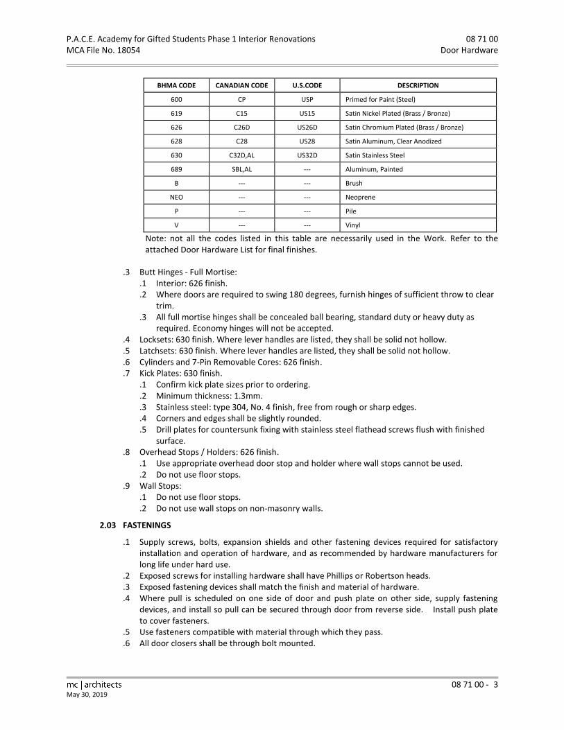
P.A.C.E. Academy for Gifted Students Phase 1 Interior Renovations 08 71 00 MCA File No. 18054 Door Hardware
08 71 00 - 3
May 30, 2019
BHMA CODE CANADIAN CODE U.S.CODE DESCRIPTION
600 CP USP Primed for Paint (Steel)
619 C15 US15 Satin Nickel Plated (Brass / Bronze)
626 C26D US26D Satin Chromium Plated (Brass / Bronze)
628 C28 US28 Satin Aluminum, Clear Anodized
630 C32D,AL US32D Satin Stainless Steel
689 SBL,AL --- Aluminum, Painted
B --- --- Brush
NEO --- --- Neoprene
P --- --- Pile
V --- --- Vinyl
Note: not all the codes listed in this table are necessarily used in the Work. Refer to the attached Door Hardware List for final finishes.
.3 Butt Hinges - Full Mortise: .1 Interior: 626 finish. .2 Where doors are required to swing 180 degrees, furnish hinges of sufficient throw to clear
trim. .3 All full mortise hinges shall be concealed ball bearing, standard duty or heavy duty as
required. Economy hinges will not be accepted. .4 Locksets: 630 finish. Where lever handles are listed, they shall be solid not hollow. .5 Latchsets: 630 finish. Where lever handles are listed, they shall be solid not hollow. .6 Cylinders and 7-Pin Removable Cores: 626 finish. .7 Kick Plates: 630 finish.
.1 Confirm kick plate sizes prior to ordering.
.2 Minimum thickness: 1.3mm.
.3 Stainless steel: type 304, No. 4 finish, free from rough or sharp edges.
.4 Corners and edges shall be slightly rounded.
.5 Drill plates for countersunk fixing with stainless steel flathead screws flush with finished surface.
.8 Overhead Stops / Holders: 626 finish. .1 Use appropriate overhead door stop and holder where wall stops cannot be used. .2 Do not use floor stops.
.9 Wall Stops: .1 Do not use floor stops. .2 Do not use wall stops on non-masonry walls.
2.03 FASTENINGS
.1 Supply screws, bolts, expansion shields and other fastening devices required for satisfactory installation and operation of hardware, and as recommended by hardware manufacturers for long life under hard use.
.2 Exposed screws for installing hardware shall have Phillips or Robertson heads.
.3 Exposed fastening devices shall match the finish and material of hardware.
.4 Where pull is scheduled on one side of door and push plate on other side, supply fastening devices, and install so pull can be secured through door from reverse side. Install push plate to cover fasteners.
.5 Use fasteners compatible with material through which they pass.
.6 All door closers shall be through bolt mounted.

08 71 00 P.A.C.E. Academy for Gifted Students Phase 1 Interior Renovations Door Hardware MCA File No. 18054
08 71 00 - 4 May 30, 2019
PART 3 EXECUTION
3.01 INSTALLATION INSTRUCTIONS
.1 Furnish door and frame manufacturers with complete instructions and templates for preparation of their work to receive hardware. Advise door and frame manufacturers to be aware that strike heights as listed in the table below are required for this Project.
.2 Furnish manufacturers' instructions for proper installation of each hardware component.
3.02 INSTALLATION
.1 Door hardware shall be installed by Section 06 20 00 - Finish Carpentry.
.2 Architectural Hardware Consultant: .1 The Hardware Supplier shall have in his employ an Architectural Hardware Consultant who
is a current member of the American Society of Hardware Consultants, and who shall be made available for consultation during the course of construction at no additional cost to the Owner.
.3 Locate and mount hardware at standard location dimensions in accordance with CSDMA, Recommended Dimensional Standards for Commercial Steel Doors and Frames, and as indicated in the following table:
HARDWARE MOUNTING HEIGHTS
HARDWARE ITEM DIMENSION ABOVE FINISH FLOOR
LOCKSET or LATCHSET 1025 mm to Centreline of Strike
DEADLOCK 1200 mm to Centreline of Strike
EXIT DEVICE 1025 mm to Centreline of Strike
PUSH PLATE and DOOR PULL 1140 mm to Centreline of Plate or Pull
.1 The Hardware Installer shall carefully check manufacturers= installation instructions supplied with hardware products for conflicts with the above noted dimensions.
.2 The Hardware Installer shall use manual or AYankee@ screw drive to turn screws into pre-drilled pilot holes for the installation of hinges on mineral core fire protection rated doors. Note that other methods of installation may void the door manufacturer=s warranty.
.3 The recommended mounting heights shall be considered a general guide unless conditions such as intermediate rails and lines of glass dictate otherwise.
.4 Locate door stops to contact doors 75 mm from latch edge.
.5 Install hardware and trim square and plumb to doors.
.6 Safeguard keys, tag with opening number, and turn over to the Owner=s representative.
.7 Supply locksets to Section 06 41 10 - Architectural Woodwork for 35mm and 45mm thick doors where such doors are part of millwork closet units. Keying shall be in accordance with the building keying system for doors.
3.03 ADJUSTING, INSPECTION, AND CLEANING
.1 Adjust hardware so that latches, locks and closers operate smoothly and without binding and with minimal resistance in use.
.2 Ensure doors with closers close firmly and against building air pressure and can be opened readily as suitable for installation.
.3 Clean hardware after installation following hardware Suppliers= recommendations.
.4 At Project completion all items of door hardware shall be clean and free from disfigurement. The Contractor shall repair or replace hardware found to be defective.
END OF SECTION
P.A.C.E. Academy for Gifted Students Phase 1 Interior Renovations 08 80 00 MCA File No. 18054 Glazing
08 80 00 - 1
May 30, 2019
PART 1 GENERAL
1.01 SECTION INCLUDES
.1 Glazing for interior doors.
1.02 RELATED SECTIONS
.1 Section 01 00 00 - General Requirements.
.2 Section 08 11 00 - Steel Doors and Frames.
1.03 REFERENCES
.1 ANSI-Z97.1-2009, Safety Glazing Materials Used in Buildings - Safety Performance Specifications and Methods of Test.
.2 ASTM-C920-14a, Standard Specification for Elastomeric Joint Sealants.
.3 ASTM-D2240-97, Standard Test Method for Rubber Property-Durometer Hardness.
.4 ASTM-E84-98, Standard Test Method for Surface Burning Characteristics of Building Materials.
.5 CAN/CGSB-12.1-2017, Safety Glazing.
.6 CAN/CGSB-12.20-M89, Structural Design of Glass for Buildings.
.7 CPSC 16 CFR 1201-2012, Safety Standard for Architectural Glazing Materials.
.8 Glass Association of North America (GANA), Glazing Manual, 2005.
1.04 PERFORMANCE REQUIREMENTS
.1 Structural Design of Glass: .1 Glass thickness:
.1 Specified glass thicknesses are minimums.
.2 Confirm glass thicknesses by analyzing Project loads and in-service conditions.
.3 Provide glass lights in the thicknesses required to meet or exceed these requirements, but not less than the minimum thickness specified.
.2 Size glass units and glass thickness in accordance with CAN/CGSB-12.20.
.3 Size glass to withstand wind loads, dead loads and positive and negative live loads as measured in accordance with ASTM-E330.
.4 Limit glass deflection to 1/175 of span to a maximum of 15mm with full recovery of glazing materials.
1.05 SUBMITTALS
.1 Submit in accordance with Section 01 00 00 – General Requirements.
.2 Submit all documentation and samples for review by Consultants at one time, prior to ordering glass products.
.3 Shop Drawings: .1 Submit Shop Drawings for the work of this section. .2 Shop Drawings shall include glass type, thicknesses, sizes, shapes, accessories, locations,
and glazing methods. .3 Shop Drawings shall include a glazing schedule listing glass types and thicknesses for each
size opening and location. .4 Samples:
.1 Submit 300mm by 300mm size samples of each type of glass specified.
1.06 QUALITY ASSURANCE
.1 Glass and glazing work of this section shall conform to good glazing practice as described in the IGMA-North American Glazing Guidelines for Sealed Insulating Glass Units for Commercial and Residential Use and the GANA Glazing Manual.

08 80 00 P.A.C.E. Academy for Gifted Students Phase 1 Interior Renovations Glazing MCA File No. 18054
08 80 00 - 2 May 30, 2019
.2 Submit all documentation specified to show that all Products used meet or exceed the requirements of these Specifications.
.3 All glass shall bear manufacturer's labels identifying glass type and thickness. Labels shall remain on glass until final cleaning.
.4 Fire-rated Impact-rated Glazing Material: .1 Each piece of fire-rated glazing material shall be labeled with a permanent label including
name of Product, manufacturer, testing laboratory, fire rating period, and safety glazing standards.
.2 Glazing material installed in high traffic locations subject to human impact shall be certified and labeled with a permanent label indicating the Product meets impact resistance requirements specified in CPSC 16 CFR 1201 and ANSI-Z97.1.
.5 Glazing Subcontractor shall be member in good standing of the Architectural Glass & Metal Contractors Association or the Ontario Glass & Metal Association and have a minimum of five years uninterrupted experience in successfully carrying out projects of similar size.
1.07 SITE CONDITIONS AND COORDINATION
.1 Do not install any glazing until all nearby mortar work is complete.
.2 Report to the Consultant in writing any defects in existing work, or unsatisfactory site conditions. Start no work until conditions are satisfactory. Starting work shall imply acceptance of existing conditions and surfaces.
.3 Glaze with compounds, sealants, or tapes only when glazing surfaces are at temperatures recommended by the tape or sealant manufacturer, and when the substrates are free of moisture.
.4 Cooperate with other Subcontractors and with framing Supplier(s) to ensure the work of this section is completed as specified.
1.08 WARRANTY
.1 Provide a warranty for glazing material and workmanship in accordance with the General Conditions, but for the time periods listed below.
.2 For the purposes of this article, but without limiting the generality of this article; defects or deficiencies shall include: .1 Defects or deficiencies in design, workmanship or materials forming part of the work of
this section. .2 “Materials” shall include glass and glazing, aluminum, gaskets, tapes and sealants.
PART 2 PRODUCTS
2.01 MATERIALS: FLAT GLASS
.1 Fire-Rated Glass (FRG): Clear and wireless laminated glass ceramic glazing material, minimum 8mm thick, premium (polished) surface finish, fire-rated and impact safety rated with permanent cUL logo. .1 Nippon Electric Glass Company Ltd.: FireLite Plus. Supplied by Technical Glass Products -
Canada. .2 Schott North America, Inc.: Pyran Platinum L. Supplied by Glassopolis. .3 Vetrotech Saint-Gobain North America Inc.: Keralite Select L. Supplied by F1 Glazing
Solutions Inc.
2.02 ACCESSORIES
.1 Setting Blocks: Neoprene, 80 - 90 Shore A durometer hardness to ASTM-D2240, to suit glazing method, glass light weight and area.

P.A.C.E. Academy for Gifted Students Phase 1 Interior Renovations 08 80 00 MCA File No. 18054 Glazing
08 80 00 - 3
May 30, 2019
.2 Spacer Shims: Neoprene 50 - 60 Shore A durometer hardness to ASTM-D2240, 75mm long by one half height of glazing stop by thickness to suit application. Self-adhesive on one face.
.3 Typical Glazing Tape: Preformed butyl compound with integral resilient tube spacing device, 10 - 15 Shore A durometer hardness to ASTM-D2240; coiled on release paper; size to suit glazing method, black colour.
.4 Fire Glazing Tape: Preformed and adhesive-backed, specially formulated high performance tape for use in fire protection rated doors and frames. Pemko: FG3000 Fire Glazing Tape.
.5 Sealant: One part neutral cure silicone to ASTM-C920, custom colour selected by the Consultant. .1 Dow Corning Corporation: 795 Silicone Building Sealant. .2 General Electric Canada Inc.: Silpruf Sealant.
PART 3 EXECUTION
3.01 EXAMINATION
.1 Verify that openings for glazing are correctly sized and within tolerances to maintain uniform face and edge clearances.
.2 Inspect all butt and mitre joints in framing. Seal joints found to be open with a compatible sealant prior to glazing.
.3 Verify that surfaces of glazing channels or recesses are clean, free of obstructions, and ready to receive glazing.
.4 Report to the Consultant in writing any defects in existing work, or unsatisfactory site conditions. Do not begin to install glass until all conditions are satisfactory. Starting work shall imply acceptance of existing conditions and surfaces.
3.02 PREPARATION
.1 Ensure fabricated glass will fit openings and that all required clearances to framing will be maintained.
.2 Clean contact surfaces with solvent and wipe dry.
.3 Seal porous glazing channels or recesses with substrate compatible primer or sealer.
.4 Prime surfaces scheduled to receive sealant. Ensure surfaces are free of moisture.
.5 Contractor shall take all precautions necessary to protect materials, before and after installation, from lime, mortar, water run-off from concrete or copper, careless handling of tools, weld spatter, acids, roofing tar, solvents, abrasive cleaners, and other items that could damage the glass surfaces. Do not rely on use of protective plastic films to protect materials.
3.03 INSTALLATION: GENERAL
.1 Install all materials according to manufacturers’ instructions and reviewed Shop Drawings and best practices as described in IGMA and GANA glazing manuals. Ensure each material used is compatible with the material which it contacts.
.2 Provide specified edge and face clearances and glass bite.
.3 Follow sealant manufacturer's recommendations for proper joint design, including use of joint fillers, primers, and bond breakers, as required to suit jobsite conditions.
.4 Remove excess glazing and sealant compounds, dirt, and other substances from glass and adjacent surfaces at completion of glazing work.
.5 Provide safety markings to installed glass. Do not mark glass with paint or any other substance that is hard to remove or could leave permanent stains.
.6 Replace all defective glass products and glass damaged during installation at no cost to the Owner.

08 80 00 P.A.C.E. Academy for Gifted Students Phase 1 Interior Renovations Glazing MCA File No. 18054
08 80 00 - 4 May 30, 2019
3.04 INSTALLATION: INTERIOR - DRY METHOD (TAPE AND TAPE)
.1 At fire protection rated doors use the specified fire glazing tape.
.2 Cut glazing tape to length and set against permanent stops, projecting 1.5mm above sight line.
.3 Place setting blocks at 1/3 points, with edge block maximum 150mm from corners.
.4 Rest glazing on setting blocks and push against tape for full contact at perimeter of light or unit.
.5 Cut glazing tape to length and place glazing tape on free perimeter of glazing, projecting 1.5 mm above sight line.
.6 Install removable stop without displacement of tape. Exert pressure on tape for full continuous contact.
.7 Knife trim protruding tape.
3.05 PROTECTION
.1 Contractor shall take all precautions necessary to protect stored glass and installed glass, from lime, mortar, solvents, abrasive cleaners, careless handling of tools, and any other activities by building trades that could permanently damage the glass surfaces.
.2 Install protective cover to glazing where there is a high risk of damage. Use plywood, heavy Kraft paper or non-staining transparent plastic sheet. Do not let protective materials contact surface of glass. Consult with Glazing Subcontractor to determine appropriate protective measures.
3.06 CLEANING
.1 Remove all protective materials, glazing materials, and other deposits from finished surfaces.
.2 Remove labels after work is complete.
.3 Clean glass according to instructions from glazing contractor.
.4 Do not use vigorous cleaning methods. Avoid scratching glass.
.5 Clean and restore stained or damaged surfaces in accordance with manufacturer's recommendations. Replace glass if cleaning is impossible.
3.07 GLAZING SCHEDULE
.1 Steel Doors: .1 Specified in Section 08 11 00. .2 Glazed by this section. .3 Method (interior): Interior Dry (tape and tape).
END OF SECTION

P.A.C.E. Academy for Gifted Students Phase 1 Interior Renovations 09 22 16 MCA File No. 18054 Non-Structural Metal Framing
09 22 16 - 1
May 15, 2015
PART 1 GENERAL
1.01 SECTION INCLUDES
.1 Steel framing for interior gypsum board clad partitions.
1.02 RELATED SECTIONS
.1 Section 01 00 00 - General Requirements.
.2 Section 09 29 00 - Gypsum Board
1.03 REFERENCES
.1 ASTM-A653/A653M-11, Standard Specification for Steel, Sheet, Zinc-Coated (Galvanized) or Zinc-Iron Alloy-Coated (Galvannealed) by the Hot-Dip Process.
.2 ASTM-A924/A924-10a, Standard Specification for General Requirements for Steel Sheet, Metallic-Coated by the Hot-Dip Process.
.3 ASTM-C645-96a, Standard Specification for Nonstructural Steel Framing Members.
.4 ASTM-C920-14a, Standard Specification for Elastomeric Joint Sealants.
.5 CSA-A82.31-M1980, Gypsum Board Application.
PART 2 PRODUCTS
2.01 PARTITION FRAMING MATERIALS
.1 Non-loadbearing Channel Stud Framing: to ASTM-C645, roll formed from a minimum of 0.79mm thick steel sheet, hot-dip galvanized in accordance with ASTM-A924/A924M, coating designation Z120 in accordance with ASTM-A653/A653M, for screw attachment of gypsum board and with service access holes. Stud size as indicated on Drawings.
.2 Floor and Ceiling Tracks: to ASTM-C645, in widths to suit stud sizes, hot-dip galvanized in accordance with ASTM-A924/A924M, coating designation Z120 in accordance with ASTM-A653/A653M. .1 Typical track: 32mm minimum flange height. .2 Long-leg track: 50mm minimum flange height.
.3 Metal Channel Stiffener: 38mm by 19mm size, 1.4mm thick cold rolled steel, hot-dip galvanized in accordance with ASTM-A924/A924M.
2.02 ACCESSORIES
.1 Insulating Strip: rubberized, moisture resistant 3mm thick foam strip, 12mm wide, with self-sticking adhesive on one face, lengths as required.
.2 Dampproof Course: polyethylene film, 0.15mm thick.
PART 3 EXECUTION
3.01 ERECTION
.1 Align partition tracks at floor and ceiling and secure at 600mm on centre maximum spacing for their full length with fasteners appropriate to substrate.
.2 Install dampproof course under stud floor partition tracks on slabs on grade.
.3 Place studs vertically at 400mm on centre spacing unless noted otherwise and not more than 50 mm from abutting walls, and at each side of openings and corners. Position studs in tracks at floor and ceiling. Cross brace steel studs with metal channel stiffeners as required to provide rigid installation to manufacturer=s instructions. Butt runners at wall intersections and corners.
.4 Erect metal studding to a tolerance of 3mm in 3000mm.
.5 Attach studs to bottom and ceiling track by using screws, crimp method or welding as required, unless noted otherwise on drawings.
09 22 16 P.A.C.E. Academy for Gifted Students Phase 1 Interior Renovations Non-Structural Metal Framing MCA File No. 18054
09 22 16 - 2 May 15, 2015
.6 Co-ordinate simultaneous erection of studs with installation of service lines. When erecting studs ensure web openings are aligned.
.7 Frame openings and around built-in equipment, cabinets and access panels, on four sides. Extend framing into reveals. Check clearances with equipment Suppliers.
.8 Install steel studs or furring channel between studs for attaching electrical and other boxes. Ensure that electrical boxes are not installed back to back in same stud space.
.9 Extend partitions to underside of deck or slab above, except where noted otherwise on Drawings.
.10 Maintain a clearance under beams, joists, structural slabs, floor and roof decks, and other structural elements to avoid the transfer of structural loads to the studs. Use double long-leg track slip joint in these locations.
.11 Install continuous insulating strips to isolate studs from non-insulated surfaces, or at exterior walls.
END OF SECTION

P.A.C.E. Academy for Gifted Students Phase 1 Interior Renovations 09 29 00 MCA File No. 18054 Gypsum Board
09 29 00 - 1
May 30, 2019
PART 1 GENERAL
1.01 SECTION INCLUDES
.1 Gypsum Drywall Systems: .1 Interior walls, partitions and ceilings for tape and joint compound finish. .2 Steel framing systems to receive gypsum board.
.2 Gypsum Board Attachment: .1 Gypsum board screw-attached to steel framing and furring.
1.02 RELATED SECTIONS
.1 Section 01 00 00 - General Requirements.
.2 Section 07 84 00 - Fire Stopping and Smoke Seals.
.3 Section 09 22 16 - Non-Structural Metal Framing: Interior partition stud system.
.4 Section 09 51 00 - Acoustical Ceilings.
.5 Section 09 91 00 - Painting.
.6 Supply of work which shall be installed by this Section is specified in: .1 Division 23 - Heating, Ventilating, and Air Conditioning (HVAC): To furnish access panels. .2 Division 26 - Electrical: To furnish access panels.
1.03 REFERENCES
.1 ASTM-A653/A653M-11, Standard Specification for Steel, Sheet, Zinc-Coated (Galvanized) or Zinc-Iron Alloy-Coated (Galvannealed) by the Hot-Dip Process.
.2 ASTM-A924/A924M-10a, Standard Specification for General Requirements for Steel Sheet, Metallic-Coated by the Hot-Dip Process.
.3 ASTM-C36-97, Standard Specification for Gypsum Wallboard.
.4 ASTM-C475-94, Standard Specification for Joint Compound and Joint Tape for Finishing Gypsum Board.
.5 ASTM-C840-96, Standard Specification for Application and Finishing of Gypsum Board.
.6 ASTM-C954-11, Standard Specification for Steel Drill Screws for the Application of Gypsum Panel Products or Metal Plaster Bases to Steel Studs from 0.033in (0.84mm) to 0.112in (2.84mm) in Thickness.
.7 ASTM-C1047-95, Standard Specification for Accessories for Gypsum Wallboard and Gypsum Veneer Base.
.8 ASTM-C1177/C1177M-08, Standard Specification for Glass Mat Gypsum Substrate for Use as Sheathing.
.9 ASTM-C1396/C1396M-11, Standard Specification for Gypsum Board.
1.04 ENVIRONMENTAL REQUIREMENTS
.1 Maintain temperature minimum 10C, maximum 21C for 48 hours prior to and during application of gypsum boards and joint treatment, and for at least 48 hours after completion of joint treatment. In cold weather, provide heat to the areas of work to establish required temperature range.
.2 Apply board and joint treatment to dry surfaces.
.3 Provide adequate ventilation to draw off excess moisture.
1.05 QUALITY CONTROL
.1 The work of this section shall be carried out by experienced drywallers under the continuous supervision of a competent foreman with a minimum of 5 years’ experience with work of similar size and complexity.

09 29 00 P.A.C.E. Academy for Gifted Students Phase 1 Interior Renovations Gypsum Board MCA File No. 18054
09 29 00 - 2 May 30, 2019
PART 2 PRODUCTS
2.01 BOARD MATERIALS
.1 Standard Gypsum Board (GBD): to ASTM-C36, standard gypsum panel, thickness as indicated, 1200mm wide by maximum practical length, square cut ends, tapered edges.
.1 CertainTeed Gypsum Canada Inc.: AirRenew Essential Indoor Air Quality Gypsum Board.
.2 CGC Inc.: Sheetrock Gypsum Panels.
.3 Georgia-Pacific Gypsum: ToughRock Gypsum Board. .2 Fire Resistant Gypsum Board (GBR): to ASTM-C36, fire resistant, thickness as indicated, square cut
ends, tapered edges, for certification laboratory classification. .1 CertainTeed Gypsum Canada Inc.: Type C Gypsum Board. .2 CGC Inc.: Sheetrock Firecode C Core Gypsum Panels. .3 Georgia-Pacific Gypsum: ToughRock Fireguard C Gypsum Board.
2.02 ACCESSORIES
.1 Metal Furring Runners, Hangers, Tie Wires, Inserts, Anchors: galvanized steel. .1 Hangers: minimum 3.4mm steel. .2 Tie wire: 1.6mm galvanized soft annealed steel. .3 Metal runners: 1.6mm thick cold rolled steel. Provide 38 mm by 13 mm where supported
at 900mm maximum centres and 38mm by 19mm where supported at 1200mm maximum centres.
.2 Drywall Furring Channels: 0.55mm core thickness, galvanized cold rolled steel channels, hot dip coating to ASTM-A924/A924M, coating designation Z120 in accordance with ASTM-A653/A653M, for screw attachment of gypsum board. Hat type profile, with 32mm by 22mm depth.
.3 Resilient Drywall Furring: 0.5mm base steel thickness galvanized steel, hot dip coating to ASTM-A924/A924M, coating designation Z120 in accordance with ASTM-A653/A653M, for resilient attachment of gypsum board, with perforated flanges. Canadian Gypsum Company: RC-1 Resilient Channel.
.4 AZ@ Furring Studs: 0.5mm base steel thickness, galvanized steel, hot dip coating to ASTM-A924/A924M, coating designation Z120 in accordance with ASTM-A653/A653M, for attachment of gypsum board at furred-out insulated walls, depth as shown on Drawings.
.5 Fasteners: to ASTM-C954. Stainless steel screws for exterior soffit sheathing.
.6 Panel Adhesive: to CAN/CGSB-71.25, as recommended by board manufacturer.
.7 Metal Trims, Cornerbeads, Control Joints, and Reveal Mouldings: to ASTM-C1047, 0.5mm base thickness commercial grade sheet steel, galvanized with perforated flanges; one piece length per location.
.1 Edge Trim: .1 CertainTeed Gypsum Canada Inc.: ProRoc AquaBead Corner Reinforcement L-Trim. .2 CGC Inc.: Sheetrock Paper Faced Metal Trim AL@ Shape, (B4 Series).
.2 Corner beads: .1 CertainTeed Gypsum Canada Inc.: ProRoc AquaBead Corner Reinforcement
Outside 90o. .2 CGC Inc.: Sheetrock Paper Faced Metal Outside Corner Bead, 90 degree (B1 Series).
.8 Insulating Strip: rubberized, moisture resistant, 3mm thick foam strip, 12mm wide, with self-sticking permanent adhesive on one face, lengths as required.
.9 Joint Compound and Joint Tape: to ASTM-C475, asbestos-free, as recommended by board manufacturer.

P.A.C.E. Academy for Gifted Students Phase 1 Interior Renovations 09 29 00 MCA File No. 18054 Gypsum Board
09 29 00 - 3
May 30, 2019
PART 3 EXECUTION
3.01 ERECTION
.1 Do work in accordance with ASTM-C840 except where specified otherwise.
.2 Extend partitions to underside of deck or slab unless noted otherwise on Drawings.
.3 Construct portions of partitions above doors, screens, windows, and other openings to match adjacent partition construction unless noted otherwise on Drawings.
3.02 WALL FURRING
.1 Install wall furring for gypsum board wall finishes in accordance with ASTM-C840 except where specified otherwise.
.2 Furr openings and around built-in equipment, cabinets, access panels, on four sides. Extend furring into reveals. Check clearances with equipment suppliers.
.3 Furr duct shafts, beams, columns, pipes and exposed services where indicated.
.4 Erect resilient furring transversely across studs, spaced maximum 600mm on centre and not more than 150mm from ceiling/wall juncture. Secure to each support with 25mm drywall screw.
.5 Install 150mm continuous strip of 12.7mm gypsum board along base of partitions where resilient furring is installed.
3.03 GYPSUM BOARD INSTALLATION
.1 Do not apply gypsum board until bucks, fastenings, supports, blocking, electrical and mechanical work are installed and approved.
.2 Ensure that environmental conditions have been satisfied prior to commencing work and that adjacent construction has been completed so that this work is not impeded.
.3 Apply single and double layer gypsum board as indicated on Drawings to metal furring or framing using screw fasteners. Maximum spacing of screws shall be 300mm on centre.
.4 Secure all gypsum board parallel to framing. Stagger joints on opposite sides of partition framing. Position all edges over drywall furring channels.
3.04 ACCESSORIES INSTALLATION
.1 Erect accessories straight, plumb or level, rigid and at proper plane. Use full length pieces where practical. Make joints tight, accurately aligned and rigidly secured. Mitre and fit corners accurately, free from rough edges. Secure at 150mm on centre.
.2 Install metal trims where gypsum board butts against surfaces, at edges exposed to view, having no trim concealing junction, at control joints and where otherwise indicated.
.3 Install insulating strips continuously at edges of gypsum board and metal trims abutting metal window, screen and exterior door frames, to provide thermal break.
3.05 TRIM AND REVEALS
.1 Minimize joints. Use corner pieces and splicers.
3.06 TAPING AND FILLING - GYPSUM BOARD
.1 Finish face panel joints and internal angles with joint system consisting of joint compound, joint tape and taping compound installed according to manufacturer's directions and feathered out onto panel faces.
.2 Levels of Finish: in accordance with ASTM-C840. .1 Typical finish: Level 4 finish, unless noted otherwise.
.3 Finish corner beads and trims as required with two coats of joint compound and one coat of taping compound, feathered out onto panel faces.
.4 Fill screw head depressions with joint and taping compounds to bring flush with adjacent surface of gypsum board so as to be invisible after surface finish is completed.

09 29 00 P.A.C.E. Academy for Gifted Students Phase 1 Interior Renovations Gypsum Board MCA File No. 18054
09 29 00 - 4 May 30, 2019
.5 Sand lightly to remove burred edges and other imperfections. Avoid sanding adjacent surface of board.
.6 Draw joint compound from bead to bead on board surfaces one metre or less in size.
3.07 CLEANING
.1 Remove excess joint compound from adjacent surfaces and materials, before it sets.
.2 Use joint compound to fill any depressions, holes or defective joints.
.3 Ensure that the completed work is plumb, straight and level with a smooth even texture, to receive subsequent finishes.
END OF SECTION

P.A.C.E. Academy for Gifted Students Phase 1 Interior Renovations 09 30 13 MCA File No. 18054 Ceramic Tiling
09 30 13 - 1
May 15, 2015
PART 1 GENERAL
1.01 SECTION INCLUDES
.1 Wall tile over concrete masonry units.
.2 Floor tile over concrete slab.
1.02 RELATED SECTIONS
.1 Section 01 00 00 - General Requirements.
.2 Section 03 30 00 - Cast-in-Place Concrete.
.3 Section 03 35 00 - Concrete Floor Finishing.
.4 Section 04 20 00 - Masonry.
.5 Section 07 92 00 - Sealants
.6 Section 10 28 13 - Washroom Accessories.
1.03 ALTERNATES
.1 Refer to Section 01 00 00 – General Requirements.
.2 This section specifies alternate Products. Refer to Part 2.
1.04 REFERENCE STANDARDS
.1 ANSI-A118.1-1992, Specifications for Dry-Set Portland Cement Mortar.
.2 ANSI-A118.4-1992, Specifications for Latex Portland Cement Mortar.
.3 ANSI-A118.6-1992, Specifications for Ceramic Tile Grouts.
.4 ANSI-A118.10-1993, Load Bearing, Bonded, Waterproof Membranes for Thin-Set Ceramic Tile and Dimension Stone Installations.
.5 ANSI-A136.1-1992, Organic Adhesives for Installation of Ceramic Tile.
.6 ANSI-A137.1-2012, Specification for Ceramic Tile.
.7 ASTM-C207-91(1997), Standard Specification for Hydrated Lime for Masonry Purposes.
.8 CAN/CSA-A23.1-09, Concrete Materials and Methods of Concrete Construction.
.9 CAN/CSA-A3001-13, Cementitious Materials for Use in Concrete.
.10 ISO-10545-Series, Ceramic Tiles, Standards for Testing.
.11 ISO-13006-2012, Ceramic Tiles, Definitions, Classifications, Characteristics and Marking.
.12 ISO-23599-2012, Assistive Products for Blind and Vision-Impaired Persons - Tactile Walking Surface Indicators.
.13 TTMAC - Specification Guide 09 30 00 - Tile Installation Manual, 2016-2017.
1.05 QUALITY ASSURANCE
.1 The work of this section shall be carried out by a company that is a member in good standing of the Terrazzo, Tile and Marble Association of Canada.
.2 This work shall be done under proper supervision by persons skilled in the methods following the recommendations of the manufacturer of the Products involved and having a minimum of two years proven experience.
.3 The ceramic tile Subcontractor shall provide proof of having successfully completed at least three projects of similar size and scope.
.4 Prevent any traffic over completed floors for a period of 72 hours after completion.
.5 Provide protection of finished floors subject to construction traffic.
1.06 SAMPLES
.1 Submit samples in accordance with Section 01 00 00 – General Requirements.
.2 Submit samples of grout colour for selection by the Consultant.
.3 Submit samples of each type of transition strip, control joint, and base cap specified.

09 30 13 P.A.C.E. Academy for Gifted Students Phase 1 Interior Renovations Ceramic Tiling MCA File No. 18054
09 30 13 - 2 May 15, 2015
1.07 MAINTENANCE INSTRUCTIONS
.1 Provide maintenance instructions as recommended by the material suppliers in accordance with Section 01 00 00 – General Requirements.
.2 Provide four copies of the TTMAC Maintenance Guide, latest edition, for inclusion in the Maintenance Manual.
.3 Give specific warning of any maintenance practice or material which may damage or disfigure the finished work or alter the coefficient of friction (i.e., slip resistance) of the finished surface.
1.08 MAINTENANCE MATERIAL
.1 Provide a minimum of one unopened boxes of each type and colour of tile required for the Project for maintenance use. Store where directed.
.2 Maintenance material shall be of same production run as the installed material.
1.09 ENVIRONMENTAL REQUIREMENTS
.1 Portland Cement Mortars and Bond Coats: Maintain air temperature and structural base temperature at ceramic tile installation area above 12C for 72 hours before and during installation, and 48 hours after installation and until setting materials have cured.
.2 Rapid-set Mortars or Latex Modified Mortars: Follow manufacturers= recommendations.
.3 Lighting: Ceramic tile work shall not proceed unless the permanent lighting is in place and operational or a minimum of 161Lm/m5 lighting is provided on the surface to be tiled.
.4 Disposal of Mortar, Grout, and Adhesives: .1 The Contractor and Ceramic Tiling Subcontractor shall properly dispose of, and remove
from site, all unused mortar, grout, and adhesives. .2 Do not dispose of mortar, grout, or adhesives in floor drains, manholes, or catch basins.
1.10 WARRANTY
.1 Provide a warranty for ceramic tile work in accordance with the General Conditions, but for a period of three years.
.2 The warranty shall cover the complete installation provided under this section against defective material and workmanship.
PART 2 PRODUCTS
2.01 CERAMIC TILE
.1 Porcelain Floor Tile - (POR): meeting requirements of ANSI-A137.1 or ISO-13006, 150mm by 915mm, square edges, slip resistant surface. .1 Saddlebrook XT series tile as supplied by Daltile.
Colour to be “Gravel Road” No. XT SD86. .2 Porcelain Cove Base – (POR): meeting requirements of ANSI-A137.1 or ISO-13006, 150mm by
305mm, cove base. .1 Haut Monde series base as supplied by Daltile. Colour to be “Glitterati Granite” No. HM03 (unpolished)
.3 Ceramic Wall Tile - meeting requirements of ANSI-A137.1 or ISO-13006, glazed plain face. Matching edge trim to suit application. .1 CWT-1: Colour Wheel series – Linear as supplied by Daltile.
Colour to be “Desert Grey” No. X114 .2 CWT-2: Colour Wheel series – Linear as supplied by Daltile
Colour to be “Ocean Blue” No. 1049

P.A.C.E. Academy for Gifted Students Phase 1 Interior Renovations 09 30 13 MCA File No. 18054 Ceramic Tiling
09 30 13 - 3
May 15, 2015
2.02 MORTAR AND ADHESIVE MATERIALS
.1 Portland Cement: to CAN/CSA-A5, Type 10.
.2 Sand: to CAN/CSA-A23.1, clean, washed, sharp sand, passing 1.6mm sieve.
.3 Hydrated Lime: to ASTM-C207.
.4 Water: potable and free of chemicals detrimental to mortar and grout mixes.
.5 Dry-Set Portland Cement Mortar: to ANSI-A118.1. Mapei Inc., Kerabond Dry-Set Mortar or Flextile Ltd., No. 51 Floor and Wall Mix.
.6 Latex-Portland Cement Mortar: to ANSI-A118.4. .1 Ardex Engineered Cements: Ardex X77 Microtec Fiber Reinforced, Polymer Modified Thin
Set Mortar. .2 Flextile Ltd.: Flextile 51 Floor and Wall Mortar Mix with Flextile 43 Thin Set Mortar
Additive. .3 Laticrete International Inc.: Floor=N Wall Thin-Set with Laticrete 3701 Latex Grout and
Mortar Admix. .4 Mapei Inc.: Kerabond Dry-Set Mortar and Keralastic Liquid Flexible Additive. .5 TEC: Super Flex - Premium Latex Modified Thin Set Mortar.
.7 Organic Adhesive: to ANSI-A136.1, Type II. .1 Ardex Engineered Cements: Ardex D14 Type 1 Premixed Tile Adhesive. .2 Flextile Ltd.: Flextile No. 200 Wall and Floor Adhesive. .3 Laticrete International Inc.: Laticrete 15 Multi-Mastic Ceramic Tile Adhesive. .4 Mapei Inc.: KER 909 Ceramic Wall Tile Adhesive. .5 TEC: Ceramic Tile Adhesive.
.8 Latex Additive: formulated for use in Portland cement mortars and leveling coats. .1 Ardex Engineered Cements: Ardex E90 Mortar Admix. .2 Flextile Ltd.: Flextile Mortar Additive No. 43 or No. 44. .3 Laticrete International Inc.: Laticrete 3701 Latex Grout and Mortar Admix. .4 Mapei Inc.: Keralastic Liquid Flexible Additive .5 TEC: XtraFlex - Premium Acrylic Mortar Additive.
2.03 GROUT
.1 Latex-Portland Cement Sanded Grout: to ANSI-A118.6, consisting of blended Portland cement, aggregates, and pigments with latex additive. Colours to be selected by the Consultant. .1 Ardex Engineered Cements: Ardex FL Rapid Set, Flexible, Sanded Grout. .2 Flextile Ltd.: Flextile Polymer Modified Floor Grout, 600 Series. .3 Laticrete International, Inc.: Laticrete Floor Grout and Joint Filler, 500 Series with Laticrete
1776 Grout Admix Plus. .4 Mapei Inc.: KER 200 Sanded Grout. .5 TEC: AccuColor - Premium Sanded Grout.
.2 Latex-Portland Cement Unsanded Grout: to ANSI-A118.6, consisting of blended Portland cement, aggregates, and pigments with latex additive. Colours to be selected by the Consultant. .1 Ardex Engineered Cements: Ardex FG-C Microtec Unsanded Floor and Wall Grout. .2 Flextile Ltd.: Flextile Polymer Modified Wall Grout, 500 Series. .3 Laticrete International, Inc.: Laticrete Dry-Set Wall Grout, 600 Series with Laticrete 1776
Grout Admix Plus. .4 Mapei Inc.: KER 800 Unsanded Grout. .5 TEC: AccuColor-Premium Unsanded Grout.
.3 One Component Stain and Mildew Resistant Grout: Flextile Ltd., Colour Max Urethane Base Grout.
.4 Grout preparation: follow manufacturer=s printed instructions.

09 30 13 P.A.C.E. Academy for Gifted Students Phase 1 Interior Renovations Ceramic Tiling MCA File No. 18054
09 30 13 - 4 May 15, 2015
2.04 ACCESSORIES
.1 Divider Strips: zinc, 1.6mm thick by depth of coating.
.2 Sealant: in accordance with Section 07 92 00 - Sealants. Colour will be selected by the Consultant.
.3 Floor Sealer and Protective Coating: supply and apply to tile and grout supplier=s recommendations. Provide data sheets to Owner for all sealers and coatings used.
.4 Transition Strips: .1 Porcelain Tile to Sealed Concrete: Satin anodized aluminum profile with textured, sloped
exposed surface, tapered leading edge, integrated trapezoid-perforated anchoring leg, and integrated grout joint spacer. Schlüter-RENO-RAMP, size to suit tile thickness.
.2 Porcelain Tile to Vinyl Composition Tile: Satin anodized aluminum profile with sloped exposed surface, 4mm high leading edge, integrated trapezoid-perforated anchoring leg. Schlüter-RENO-U, size to suit tile thickness.
.3 Porcelain Tile to Carpet: Satin anodized aluminum profile with sloped exposed surface, 6mm deep channel below exposed surface, integrated trapezoid-perforated anchoring leg. Schlüter-RENO-TK. Provide radius perforation for curves.
.5 Control Joints: Type 304 stainless steel profile with integrated trapezoid-perforated anchoring legs, connected by a 11mm wide replaceable thermoplastic rubber movement zone. Schlüter-DILEX-KSN, size to suit tile thickness. Colour will be selected by the Consultant.
.6 Base Cap: Satin anodized aluminum profile with integrated trapezoid-perforated anchoring leg, and complete with prefabricated corners. Schlüter-SCHIENE, size to suit tile thickness.
2.05 MORTAR AND ADHESIVE MIXES
.1 Mortar Bed for Floors: 1 part Portland cement, 4 parts sand, 1 part water. Adjust water volume depending on water content of sand. Use latex additive in modification of mortar bed. Alternatively use Flextile Ltd., 4:1 Dry Pack Mortar and No. 44 Latex Additive.
.2 Leveling Coat: 1 part Portland cement, 4 parts sand, minimum 1/10 part latex additive, 1 part water including latex additive. Alternatively use Flextile Ltd., No.59 Flex-Flo or No.5900 Flex-Flo Plus. Alternatively use Flextile Ltd., No.59 Flex-Flo or No.5900 Flex-Flo Plus.
.3 Measure mortar ingredients by volume.
.4 Dry Set Mortar: mix to manufacturer's instructions.
.5 Organic Adhesive: pre-mixed, as recommended by the tile manufacturer for application to installed substrate.
PART 3 EXECUTION
3.01 EXAMINATION AND PREPARATION
.1 Surfaces shall be clean, dimensionally stable, cured, and free of contaminants such as oil, sealers and curing compounds.
.2 Concrete Substrate Finish: Cure concrete for a minimum of 28 days. .1 Thin-set applications: steel trowel and fine broom finish. .2 Mortar bed applications: screed finish. .3 Mortar bed applications with a cleavage membrane: Steel trowel finish.
.3 Substrate Surface Variation: .1 Mortar bed applications: 6mm in 3000mm maximum. .2 Thin-set applications: 3mm in 3000mm and 1.5mm in 305mm maximum. .3 Vertical surfaces: 3mm in 2400 mm.
.4 Examine areas in which the work of this section is to be applied and notify the Consultant of any deficiencies which must be corrected before work can commence.
.5 Do not proceed with the work until improper conditions are corrected.
P.A.C.E. Academy for Gifted Students Phase 1 Interior Renovations 09 30 13 MCA File No. 18054 Ceramic Tiling
09 30 13 - 5
May 15, 2015
.6 Protect other work during installation and protect tile work until properly set, grouted and sealed.
.7 Co-ordinate the work of this section related to the work of other sections.
.8 Apply a leveling coat on uneven surfaces, or surfaces which do not guarantee a plumb or level finish to the tile.
.9 Install mortar bed as required in new washrooms to bring surface to correct elevation for installation of floor tile
3.02 WORKMANSHIP
.1 Perform all work in accordance with the requirements of the TTMAC Tile Installation Manual.
.2 Apply tile or backing coats to clean and sound surfaces.
.3 Bring every fourth course, vertical and horizontal, to plumb and level continuous lines.
.4 Thoroughly back-up with mortar all cove, cap, nosing, trimmer, and moulded or shaped pieces and secure firmly in place.
.5 Fit tile around corners, fixtures, drains and other built-in objects. Maintain uniform joint appearance. Cut edges smooth, even, and free from chipping. Edges resulting from splitting are not acceptable. Rub exposed edges smooth with abrasive stone.
.6 Leave or cut opening to correct sizes to receive accessories, fittings, or other built-in work.
.7 Drill tile for hardware and for pipes where possible. Otherwise, at pipes and fittings, fit tile closely so that escutcheons cover cut edges of tile.
.8 Maximum finished surface tolerance shall be 1:800.
.9 Make joints between tile uniform, plumb, straight, true, even and flush with adjacent tile with a tolerance of 1mm per 3mm of joint width. Ensure sheet layout is not visible after installation. Align patterns. Align joints of wall tile with floor tile.
.10 Lay out tiles so that fields are centred on areas, and according to the drawings with perimeter and cut tiles a minimum 1/2 size. Maintain height of panels in full courses to nearest indicated dimension.
.11 Keep 2/3 of the depth of grout joints free of setting material.
.12 Sound tiles after setting and replace hollow- sounding units to obtain full bond.
.13 Make internal angles square, external angles rounded.
.14 Use round edged tiles at termination of wall tile panels, except where panel abuts projecting surface or differing plane.
.15 Install divider strips at junction of tile flooring and dissimilar materials.
.16 Allow a minimum of 24 hours after installation of tiles before grouting. Grouting shall be in accordance with manufacturer=s directions. Fill joints solidly.
.17 Finished grout shall be uniform in colour, smooth and without voids, pinholes or low spots. Cover setting bed completely.
.18 Protect tiles from grout staining. Test in advance and pre-seal tile if required. Follow grout manufacturer=s recommendations for grout and residue removal. Remove excess grout and polish with clean cloths.
.19 Clean installed tile surfaces after installation and grouting has cured. Final cleaning is specified in Section 01 00 00 – General Requirements.
.20 Finished tile work shall be free of tiles which are pitted, chipped, cracked or scratched.
.21 Install expansion joints where indicated. Install specified control joints at 6000mm on centre in each direction unless indicated otherwise. Make joint width same as tile joints. Where indicated, fill control joints with sealant in accordance with Section 07 92 00 - Sealants. Keep building expansion joints free of mortar and grout. Match colour of sealant to colour of grouted joints.
.22 Transition Strips: .1 Install specified transition strips where ceramic tile flooring meets dissimilar flooring. .2 Install transition strips fully bonded to floors following the manufacturers=
recommendations.

09 30 13 P.A.C.E. Academy for Gifted Students Phase 1 Interior Renovations Ceramic Tiling MCA File No. 18054
09 30 13 - 6 May 15, 2015
.3 Install strips under doors at openings. .23 Caulk around piping and fittings extending through tiled surfaces. Tool to a smooth, flush
surface, free from air bubbles and contamination. Provide backer rod under sealant. .24 Protect installed areas from traffic until setting materials have cured for the periods specified in
the TTMAC Tile Installation Manual. .25 Barricade grouted areas to prevent foot traffic for 24 hours after grouting. .26 Apply floor sealer and protective coating in accordance with the manufacturer=s instructions.
3.03 TILE INSTALLATION SCHEDULE
.1 Walls: .1 Masonry: Thin-set method. Install in accordance with TTMAC detail 303W-2016-2017, with
latex-Portland cement mortar bond coat and latex-Portland cement unsanded grout. .2 Gypsum Board: Thin-set method. Install in accordance with TTMAC detail
304W-2016-2017, with organic adhesive and latex-Portland cement unsanded grout. .2 Floors:
.1 Concrete Slabs - Thin-set method (in Corridors): Install in accordance with TTMAC detail 311F-2016-2017, Detail A, with latex-Portland cement mortar bond coat and latex-Portland cement sanded grout. Back butter tile and set on freshly notched thin-set mortar.
.2 Concrete Slabs - Mortar Bed (in Washrooms): .1 Mortar bed: latex-modified mortar bed, minimum 30 mm thick at drains, and sloped
at 6 mm in 300 mm to drains. Finish surface of mortar bed to match corridor concrete slab elevation at door thresholds
.2 Install tile over mortar bed that has cured a minimum of 24 hours in accordance with TTMAC detail 319SR-2016-2017, with latex-Portland cement mortar bond coat and latex-Portland cement sanded grout.
.3 Notch thin-set bond coat in straight lines. Backbutter tile and set on the freshly notched thin-set mortar while moving the tile back and forth at 90 to the notches.
.3 Control Joints and Expansion Joints: .1 Install tile as detailed and in accordance with TTMAC detail 301MJ-2016-2017. .2 Keep all control and expansion joints free of setting materials.
END OF SECTION

P.A.C.E. Academy for Gifted Students Phase 1 Interior Renovations 09 51 00 MCA File No. 18054 Acoustical Ceilings
09 51 00 - 1
May 30, 2019
PART 1 GENERAL
1.01 SECTION INCLUDES
.1 Acoustical ceiling panels.
.2 Suspension systems and trim for acoustical ceilings.
1.02 RELATED SECTIONS
.1 Section 01 00 00 - General Requirements.
.2 Division 23 – Heating, Ventilating, and Air Conditioning (HVAC): Mechanical Ceiling Components.
.3 Division 26 - Electrical: Electrical Ceiling Components.
1.03 REFERENCES
.1 ASTM-C635/C635M-07, Standard Specification for the Manufacture, Performance, and Testing of Metal Suspension Systems for Acoustical Tile and Lay In Panel Ceilings.
.2 ASTM-C636/C636M-08, Standard Practice for Installation of Metal Ceiling Suspension Systems for Acoustical Tile and Lay In Panels.
.3 CAN/CGSB-92.1-M89, Sound Absorptive Prefabricated Acoustical Units.
.4 CSA-B111-1974, Wire Nails, Spikes and Staples.
.5 CAN/ULC-S102-M88, Standard Method of Test for Surface Burning Characteristics of Building Materials and Assemblies.
1.04 DESIGN REQUIREMENTS
.1 Maximum Deflection: 1/360th of span to ASTM-C635/C635M deflection test.
.2 Installation Tolerances: to ASTM-C636/C636M.
1.05 SUBMITTALS
.1 Submit in accordance with Section 01 00 00 – General Requirements.
.2 Shop Drawings: .1 Submit Shop Drawings for the work of this section. .2 Shop Drawings shall indicate layout and details of acoustical ceilings including locations of
items which are to be coordinated with or supported by the ceilings. .3 Samples:
.1 Submit duplicate 300mm by 300mm samples of each type of acoustical unit.
.2 Submit one representative model of ceiling suspension system for approval.
.3 Ceiling system sample shall show basic construction and assembly, treatment at walls, recessed fixtures, splicing, interlocking, finishes, and acoustical unit installation.
1.06 REGULATORY REQUIREMENTS
.1 Fire-resistance Rated Floor/Ceiling and Roof/Ceiling Assembly: certified by a Canadian Certification Organization accredited by the Standards Council of Canada.
.2 Fire-resistance Rated Suspension System: certified by a Canadian certification organization accredited by the Standards Council of Canada.
1.07 ENVIRONMENTAL REQUIREMENTS
.1 Permit wet work to dry before commencement of acoustical panel installation.
.2 Maintain uniform minimum temperature of 15C and humidity of 20 to 40% before and during installation.
.3 Deliver finish materials in unopened packaging provided by manufacturer.
.4 Store materials in work area 48 hours prior to installation, in protected dry areas.

09 51 00 P.A.C.E. Academy for Gifted Students Phase 1 Interior Renovations Acoustical Ceilings MCA File No. 18054
09 51 00 - 2 May 30, 2019
1.08 MAINTENANCE MATERIALS
.1 Provide one sealed carton of acoustical panels for each pattern and type required for the Project.
.2 Extra materials shall be from the same production run as installed materials.
.3 Clearly identify each type of acoustical unit, including colour and texture.
.4 Store where directed by the Owner.
1.09 WARRANTY
.1 Provide a warranty for acoustical ceilings in accordance with the General Conditions, but for a period of two years.
.2 The warranty shall cover the complete installation provided under this section against defective material and workmanship.
PART 2 PRODUCTS
2.01 ACOUSTICAL PANELS
.1 Acoustical Panels Type 1 (ACT1) - Typical non-fire rated ceilings: to CAN/CGSB-92.1. .1 Type: Mineral composition acoustical units, sag resistant. .2 Pattern: non-directional fissured. .3 Flame spread rating of 25 or less. .4 Smoke developed class of 50 or less. .5 Noise reduction coefficient (NRC) designation of 0.55 minimum. .6 Ceiling Attenuation Class (CAC) designation of 30 minimum. .7 Light reflectance range of 0.80 and above. .8 Edge type: square. .9 Colour: white. .10 Size: 16 mm minimum thickness, 610mm by 1220mm. .11 Shape: flat. .12 Acceptable Products:
.1 Armstrong World Industries Canada Ltd.: Fine Fissured 1729.
.2 CertainTeed Ceilings: Vantage 10, VAN-197.
.3 CGC Interiors: Radar ClimaPlus 2410. .2 Acoustical Panels Type 2 (ACT2) - Fire rated ceilings: to CAN/CGSB-92.1.
.1 Type: Mineral composition acoustical units, sag resistant.
.2 Pattern: non-directional fissured.
.3 Flame spread rating of 25 or less.
.4 Smoke developed class of 50 or less.
.5 Noise reduction coefficient (NRC) designation of 0.55 minimum.
.6 Ceiling Attenuation Class (CAC) designation of 30 minimum.
.7 Light reflectance range of 0.80 and above.
.8 Edge type: square.
.9 Colour: white.
.10 Size: 16mm minimum thickness, 610mm by 1220mm.
.11 Shape: flat.
.12 Minimum weight: 4.88kg/m5
.13 Acceptable Products: .1 Armstrong World Industries Canada Ltd.: Fine Fissured 1830. .2 CertainTeed Ceilings: Protectone Vantage 10, PVN-197. .3 CGC Interiors: Radar ClimaPlus 2415.
.3 Acoustical Panels Type 3 (ACT3) - Washable non-fire rated ceilings: .1 Type: Mineral composition acoustical units with soil-resistant vinyl film surface .2 Pattern: non-perforated.
P.A.C.E. Academy for Gifted Students Phase 1 Interior Renovations 09 51 00 MCA File No. 18054 Acoustical Ceilings
09 51 00 - 3
May 30, 2019
.3 Flame spread rating of 25 or less.
.4 Smoke developed class of 50 or less.
.5 Noise reduction coefficient (NRC) designation of 0.10 minimum.
.6 Ceiling Attenuation Class (CAC) designation of 40 minimum.
.7 Light reflectance range of 0.75 and above.
.8 Edge type: square.
.9 Colour: white.
.10 Size: 16mm minimum thickness, 610mm by 1220mm.
.11 Shape: flat.
.12 Minimum weight: 4.8 kg/m5
.13 Acceptable Products: .1 Armstrong World Industries Canada Ltd.: Clean Room VL - Nonperforated, 870. .2 CertainTeed Ceilings: Safetone Vinylshield C 1170-CRF-1 Nonperforated. .3 CGC Interiors: Clean Room ClimaPlus Class 100 Panels, 56091.
2.02 SUSPENSION SYSTEM
.1 Intermediate duty system to ASTM-C635.
.2 Basic Materials for Suspension System: commercial quality cold rolled steel zinc coated.
.3 Exposed Tee-bar Grid Components: white colour. Components die cut. Main tee, 43mm high, with double web, rectangular bulb and 25mm rolled cap on exposed face. Cross tee, 43mm high, with rectangular bulb; web extended to form positive interlock with main tee webs; lower flange extended and offset to provide flush intersection; wall moulding, 22mm wide by 22mm high, finished to match main tees and cross tees.
.4 Suspension System Type 1 (T-bar1) - Non-fire rated ceilings: .1 Two directional exposed tee-bar grid, double web. .2 Armstrong World Industries Canada Ltd.: Prelude ML Exposed Tee System. .3 Bailey Metal Products Limited: Lance-Lock System 900 (BEH). .4 CertainTeed Ceilings: Classic Hook System. .5 CGC Interiors: Donn DX Exposed Grid Suspension System. .6 Chicago Metallic Corporation: Series 1200 Suspension System.
.5 Suspension System Type 2 (T-bar2) - Fire-resistance rated ceilings: .1 Certified for use in rated assembly, certification organization=s design No. as noted in the
Construction Legend for floor/ceiling and roof/ceiling assemblies. .2 Two directional exposed tee-bar grid. .3 Bailey Metal Products Limited: Lance-Lock System 1800 (BEF). .4 CGC Interiors: Donn DXL Exposed Grid Suspension System. .5 Chicago Metallic Corporation: Fire Front 1250 Snap-Grid System.
.6 Suspension System Type 3 (T-bar3) - Washable non-fire rated ceilings: .1 Two directional exposed tee-bar grid, double web. .2 Hot dipped galvanized, painted steel tee with painted aluminum cap. .3 Armstrong World Industries Canada Ltd.: Prelude XL for Exterior Applications. .4 Bailey Metal Products Limited: Lance-Lock System 700. .5 CertainTeed Ceilings: Classic Aluminum Cap Hook System. .6 CGC Interiors: Donn ZXLA Suspension System. .7 Chicago Metallic Corporation: Series 1830 HDG Suspension System.
2.03 ACCESSORIES
.1 Hanger Wire: galvanized soft annealed steel wire, 3.6mm minimum diameter. .1 Fire-rated assemblies: To certification laboratory design requirements.
.2 Hanger Inserts: purpose made.
.3 Carrying Channels: 1.2mm cold rolled galvanized steel channel, 38mm deep with 19mm flanges.

09 51 00 P.A.C.E. Academy for Gifted Students Phase 1 Interior Renovations Acoustical Ceilings MCA File No. 18054
09 51 00 - 4 May 30, 2019
.4 Hanger Anchoring Devices: Philips Red Head by Philips Drill Company of Canada Limited. .1 T32, self-drilling for use in concrete deck. .2 WS-3822 wedge anchor with tie wire insert for use in composite concrete and steel deck. .3 SDI-3822 for use in steel deck, with screw eye bolts to suit inserts.
.5 Suspension System Accessories: splices, bull nose corner caps, hold down clips, wire ties, retainers and typical flush wall moulding, to complement suspension system components, as recommended by system manufacturer.
PART 3 EXECUTION
3.01 EXAMINATION
.1 Do not install acoustical panels and tiles until work above ceiling has been inspected by the Consultant.
3.02 INSTALLATION - SUSPENSION SYSTEM
.1 Installation: in accordance with ASTM-C636 except where specified otherwise.
.2 Install suspension system to manufacturer's instructions and certification organization=s tested design requirements where referenced.
.3 Do not erect ceiling suspension system until work above ceiling has been inspected by the Consultant.
.4 Do not secure hangers to fluted steel floor or roof deck. Secure hangers to overhead structure using attachment methods as required for particular structure and acceptable to the Consultant. Where structural spacing exceeds ceiling hanger spacing, provide double carrying channels nested and placed perpendicular to and on top of bottom flange of steel beams or on top of the lower chords of the open web steel joists, and secured to each joist with three loops of 1.2 mm galvanized soft steel wire.
.5 Where obstructions interfere with the placement of ceiling hangers, provide double carrying channels nested and hung from the structure above on both sides of the obstruction.
.6 Provide isolation hangers at all hangers where indicated as required for specific ceiling assemblies.
.7 Install hangers on main tees spaced at maximum 1200mm centres and within 150mm from ends of main tees and tee splices.
.8 Lay out with border units not less than 50% of standard unit width and according to reflected ceiling plans.
.9 Ensure suspension system is coordinated with location of related components.
.10 Install typical wall moulding to provide correct ceiling height.
.11 Completed suspension system shall support super-imposed loads, such as lighting fixtures, diffusers, grilles, speakers and other ceiling mounted fixtures.
.12 Support at light fixtures and diffusers with additional ceiling suspension hangers within 150mm of each corner and at maximum 600mm around perimeter of fixture. Install an additional hanger immediately above each fastener for ceiling mounted curtain tracks.
.13 Interlock cross member to main runner to provide rigid assembly. Ensure all main tee splices and cross tee end clips are fully engaged.
.14 Frame at openings for light fixtures, air diffusers, speakers and at changes in ceiling heights.
.15 Finished ceiling system shall be square with adjoining walls and level within 6mm in 3000mm.
3.03 INSTALLATION - ACOUSTICAL PANELS
.1 Install acoustical panels and tiles in ceiling suspension system.
.2 In fire rated ceiling systems, secure lay-in panels with hold-down clips where required by the assembly design and protect over light fixtures, diffusers, air return grilles and other appurtenances according to certification organization=s design requirements.

P.A.C.E. Academy for Gifted Students Phase 1 Interior Renovations 09 51 00 MCA File No. 18054 Acoustical Ceilings
09 51 00 - 5
May 30, 2019
.3 Scribe acoustic units accurately and neatly to fit adjacent work. Butt joints tight, terminate edges with moulding.
3.04 INTERFACE WITH OTHER WORK
.1 Co-ordinate ceiling work to accommodate components of other sections, to be built into acoustical ceiling components, such as light fixtures, diffusers, speakers and sprinkler heads.
.2 Neatly cut acoustical units to fit tightly around all building elements that penetrate ceiling.
3.05 CLEANING
.1 Clean with non-solvent based commercial cleaners.
.2 Touch up minor scratches, abrasions, voids and other defects in painted surfaces as acceptable. Replace damaged sections when touch-up is not acceptable to the Consultant.
.3 Replace components which are visibly damaged, marred or not cleanable.
.4 Remove all excess material and debris when work of this section is completed.
3.06 SCHEDULE
.1 Typical Non-fire Rated Ceilings: .1 Acoustical panel: all Type 1 acoustical panels. .2 Suspension system: all Type 1 suspension systems.
.2 Fire Rated Floor/Ceiling Assemblies: comply fully with the certification organization=s requirements for the ceiling assembly design options listed below. .1 Option No. 1 - ULC Design No. I217.
.1 Acoustical panel: Armstrong Type 2 acoustical panel only.
.2 Suspension system: CGC Type 2 suspension system only.
.3 Hold down clips: not required if acoustic panel weighs at least 4.88kg/m2. .2 Option No. 2 - ULC Design No. G218:
.1 Acoustical panel: CertainTeed Type 2 acoustical panel only.
.2 Suspension system: all Type 2 suspension systems.
.3 Hold down clips: required. .3 Option No. 3 - ITS CMC/FCA 120-03:
.1 Acoustical panel: all Type 2 acoustical panels.
.2 Suspension system: Chicago Metallic Type 2 suspension system only.
.3 Hold down clips: not required if acoustic panel weighs at least 4.88kg/m2. .3 Fire Rated Roof/Ceiling Assemblies: comply fully with the certification organization=s
requirements for the ceiling assembly design options listed below. .1 Option No. 1 - ULC Design No. R210.
.1 Acoustical panel: Armstrong Type 2 acoustical panel only.
.2 Suspension system: CGC Type 2 suspension system only.
.3 Hold down clips: required. .2 Option No. 2 - UL Design No. P259.
.1 Acoustical panel: CertainTeed Type 2 acoustical panel only.
.2 Suspension system: all Type 2 suspension systems.
.3 Hold down clips: required. .3 Option No. 3 - ITS CMC/FCA 60-02.
.1 Acoustical panel: all Type 2 acoustical panels.
.2 Suspension systems: Chicago Metallic Type 2 suspension system only.
.3 Hold down clips: not required if acoustic panel weights at least 4.88 kg/m5. .4 Washable Non- fire Rated Ceilings:
.1 Acoustical panel: all Type 3 acoustical panels.
.2 Suspension system: all Type 3 suspension systems.
END OF SECTION

P.A.C.E. Academy for Gifted Students Phase 1 Interior Renovations 09 65 19 MCA File No. 18054 Resilient Tile Flooring
09 65 19 - 1
May 30, 2019
PART 1 GENERAL
1.01 SECTION INCLUDES
.1 Resilient tile flooring.
.2 Flooring preparation.
1.02 RELATED SECTIONS
.1 Section 01 00 00 - General Requirements.
.2 Section 03 35 00 - Concrete Floor Finishing.
.3 Section 09 30 13 - Ceramic Tile.
1.03 ALTERNATES
.1 Refer to Section 01 00 00 - Alternates.
.2 Provide alternate prices for work specified in Part 2 of this section.
1.04 REFERENCES
.1 ASTM-F1066-04(2010)e1, Standard Specification for Vinyl Composition Floor Tile.
.2 ASTM-F1700-04(2010), Standard Specification for Solid Vinyl Floor Tile.
.3 ASTM-F1861-08(2012)e1, Standard Specification for Resilient Wall Base.
.4 CAN/CGSB-25.20-95, Surface Sealer for Floors.
.5 CAN/CGSB-25.21-95, Detergent-Resistant Floor Polish.
1.05 SAMPLES
.1 Submit samples in accordance with Section 01 00 00 – General Requirements.
.2 Submit duplicate full size tiles, 300mm long base as specified.
.3 Submit colour samples of flooring accessories for selection by the Consultant.
.4 Submit samples of each type of resilient transition strip specified.
1.06 CLOSEOUT SUBMITTALS
.1 Provide maintenance data for resilient flooring for incorporation into manual specified in Section 01 00 00 – General Requirements.
1.07 EXTRA MATERIALS
.1 Provide extra materials of resilient tile flooring and base in accordance with Section 01 00 00 – General Requirements.
.2 Provide one unopened box of flooring installed of each colour, pattern and type of flooring material required for this Project for maintenance use.
.3 Provide one 3600mm length of each type and colour of resilient base required for this Project for maintenance use.
.4 Extra materials shall be from same production run as installed materials.
.5 Clearly identify each container of floor tile and label each piece of resilient base.
.6 Store where directed by the Owner.
1.08 ENVIRONMENTAL REQUIREMENTS
.1 Maintain air temperature, structural base temperature, and humidity control at flooring installation area above 20C for 48 hours before, during and for 48 hours after installation.
1.09 WARRANTY
.1 Submit the manufacturer=s warranty for the Products of this section in accordance with the General Conditions, but for a period of five years.

09 65 19 P.A.C.E. Academy for Gifted Students Phase 1 Interior Renovations Resilient Tile Flooring MCA File No. 18054
09 65 19 - 2 May 30, 2019
PART 2 PRODUCTS
2.01 FLOORING MATERIALS
.1 Vinyl Tile (VT): to ASTM-F1700, 3mm thick, 300mm by 300mm size. .1 Delane series tile as manufactured by Flexco
Colours: VT-1 “Medium Grey” VT-2 “Tusk” No. 319
.2 Alternatives: Refer to Section 01 00 00 – General Requirements. .1 Vinyl Composition Tile (VCT): to ASTM-F1066, 3 mm thick, 300 mm by 300 mm size.
Colour will be selected by the Consultant from the standard range. Acceptable Manufacturers: .1 Amtico: ColoursPlus, Fortress Elements. .2 Armstrong: Excelon, Imperial Texture. .3 Flextile: Flex-Thru Architectural Collection. .4 Johnsonite: Azrock VCT. .5 Mannington Commercial: Essentials/Designer Essentials.
.2 Resilient Base (RB): to ASTM-F1861, Type TS-vulcanized thermoset rubber Style B-coved, typical. Minimum 1200mm length and 100mm high by 3mm thick, with grooved back. .1 Coved base:
.1 Johnsonite: Traditional Rubber Wall Base, DC. Colour: “Charcoal WG” No. 20
.2 Mannington Commercial: Optimum Edge Coved Wall Base. Colour: to be selected from manufacturer’s standard colour range
.3 Roppe Corporation: Pinnacle Rubber Standard Toe Base. Colour: to be selected from manufacturer’s standard colour range
2.02 FLOORING ACCESSORIES
.1 Primers and Adhesives: .1 Primer: as recommended by flooring manufacturer for specific material on applicable
substrate, above, at or below grade. .2 Adhesive: Armstrong S-750 Premium Floor Tile Adhesive. Equivalent Products from Amtico,
Flextile, Johnsonite, or Mannington are also acceptable. Ensure flooring materials and adhesive are compatible.
.2 Sub-floor Filler and Leveler: as recommended by flooring manufacturer for use with their Product.
.3 Sealer: type recommended by flooring manufacturer, meeting the requirements of CAN/CGSB-25.20.
.4 Floor Protection: heavy kraft paper laminated with non-staining adhesive to both sides of glass fibre reinforcing ply.
.5 Wax: self-polishing emulsion type as recommended by flooring manufacturer.
.6 Resilient Transition Strips: Vinyl, in colours selected by the Consultant. .1 Vinyl Composition Tile to Sealed Concrete:
.1 Johnsonite: RRS-XX-C Reducing Strip.
.2 Roppe Corporation: No. 45 Reducer Strip. .2 Vinyl Composition Tile to Vinyl Composition Tile:
.1 Johnsonite: FS-XX-DW2 Feature Strip.
.2 Roppe Corporation: No. 195 Feature Strip.

P.A.C.E. Academy for Gifted Students Phase 1 Interior Renovations 09 65 19 MCA File No. 18054 Resilient Tile Flooring
09 65 19 - 3
May 30, 2019
PART 3 EXECUTION
3.01 SITE VERIFICATION OF CONDITIONS
.1 Ensure concrete floors are dry, by using test methods recommended by tile manufacturer.
.2 Check for dusting and other defects which may affect bonding of adhesive.
.3 If the test results exceed the limitations specified to not proceed until the problem is corrected and satisfactory test results are obtained.
3.02 SUB-FLOOR TREATMENT
.1 Remove sub-floor ridges and bumps. Fill low spots, cracks, joints, holes and other defects with sub-floor filler.
.2 Clean floor thoroughly of any old adhesives, dirt, oil, grease and other material which may affect adhesive bonding and cause telegraphing. Apply filler; trowel and float to leave smooth, flat hard surface. Prohibit traffic until filler has cured and is dry.
.3 Prime concrete to flooring manufacturer's printed instructions.
.4 At junctions with adjacent thicker floor finishes, raise subfloor level under resilient tile by applying an appropriate cementitious sub-floor leveler and feathering out edges so that slopes do not exceed 1:150. Ensure finish floor surface is flush across such junctions.
3.03 TILE APPLICATION
.1 Use only adhesives recommended and approved by the flooring manufacturer.
.2 Apply adhesive uniformly using recommended trowel in accordance with flooring manufacturer's instructions. Do not spread more adhesive than can be covered by flooring before initial set takes place.
.3 Lay flooring with joints parallel to building lines to produce symmetrical tile pattern. Border tiles shall be a minimum half tile width.
.4 Install flooring to square grid pattern with all joints aligned with continuous joints flowing with direction of mottle, with pattern grain parallel for all units and parallel to width of room.
.5 As installation progresses, and after installation, roll flooring in 2 directions from centre area of work with 45 kg minimum three section roller to ensure full adhesion.
.6 Cut tile and fit neatly around fixed objects. Continue flooring over areas which will be under built-in furniture and fitments, without interrupting floor pattern.
.7 Install flooring in pan type floor access covers. Maintain floor pattern.
.8 Terminate flooring at centerline of door in openings where adjacent floor finish or colour is dissimilar.
.9 Coordinate installation of appropriate transition strips at junction with dissimilar floor materials with trades installing these materials and transition strips.
.10 Resilient Transition Strips: .1 Install specified resilient transition strips at junction with dissimilar floor materials and
coordinate installation with trades installing these materials. .2 Install resilient transition strips fully bonded to floors using manufacturer recommended
adhesive. .11 Install strips under doors at openings.
3.04 BASE APPLICATION
.1 Lay out base to keep the number of joints to a minimum. Base joints shall be at maximum length available or at internal or formed corners.
.2 Clean the substrate and prime with one coat of adhesive.
.3 Apply adhesive to back of base.
.4 Set base tightly against wall and floor surfaces and roll by using a 3 kg hand roller.
.5 Install straight and level to a variation tolerance of 1:1000.

09 65 19 P.A.C.E. Academy for Gifted Students Phase 1 Interior Renovations Resilient Tile Flooring MCA File No. 18054
09 65 19 - 4 May 30, 2019
.6 Scribe and fit to door frames and other obstructions. Use premoulded end pieces at flush door frames.
.7 Cut and miter internal corners. Wrap and scribe back of base according to approved fashion for right angle external corners, using a full bedding of adhesive. Use formed straight base material for external corners of other angles, minimum 300mm for each leg. Wrap around toeless base at external corners.
3.05 INITIAL CLEANING AND WAXING
.1 Remove excess adhesive from floor, base and wall surfaces without damage, as work progresses.
.2 Clean, seal and wax vinyl composition tile flooring and resilient base surface to flooring manufacturer's instructions immediately after installation.
.3 Final cleaning is specified in Section 01 00 00 – General Requirements.
3.06 PROTECTION OF FINISHED WORK
.1 Protect new floors from time of final set of adhesive until Project completion.
.2 Prohibit traffic on floor for 48 hours after installation.
.3 Protect floors by lapping joints of protection material a minimum of 150mm, sealing with non-asphaltic tape.
END OF SECTION

P.A.C.E. Academy for Gifted Students Phase 1 Interior Renovations 09 91 00 MCA File No. 18054 Painting
09 91 00 - 1
May 30, 2019
PART 1 GENERAL
1.01 SECTION INCLUDES
.1 Painting and surface preparation for interior unfinished surfaces as scheduled.
.2 Field-painting and surface preparation of exposed mechanical and electrical piping, conduit, ductwork and equipment.
.3 Repainting and surface preparation at areas of remodeling.
.4 Provide labour, material, equipment and services necessary for completion of the above noted work.
1.02 RELATED SECTIONS
.1 Section 01 00 00 - General Requirements.
.2 Section 04 20 00 - Masonry.
.3 Section 08 11 00 - Steel Doors and Frames: Shop coat.
.4 Section 09 29 00 - Gypsum Board.
1.03 REFERENCES
.1 The Master Painters Institute (MPI), Architectural Painting Specification Manual (APSM), latest edition.
.2 CAN/CGSB-85.10-99, Protective Coatings for Metals.
.3 CAN/CGSB-85.100-93, Painting.
1.04 SUBMITTALS
.1 Submit in accordance with Section 01 00 00 – General Requirements.
.2 Submit duplicate 200mm by 300mm sample colour cards of each paint finish and colour required, appropriately labelled with colour name, number, gloss/sheen, manufacturer, Project name, and Subcontractor name.
.3 Include specifications of materials, Products, and application procedures used to obtain finishes. Re-submit samples until acceptable to the Consultant.
.4 Colours shall match those specified in the Consultant=s colour schedule as identified by an acceptable paint manufacturer=s colour designation system.
.5 Retain samples at the Work site until completion of the Work.
.6 Two weeks before the commencement of painting and finishing, and prior to ordering materials, submit to the Consultant a complete paint finish schedule for approval. The schedule shall list the name of the paint manufacturer, the catalogue number, grade, and quality of the materials proposed for use, surfaces to be painted, room names and numbers, and colour chip sample.
.7 Submit two sets of Material Safety Data Sheets (MSDS) prior to commencement of work for review and for posting at the job site as required.
.8 Materials and Products delivered to the site shall comply with the approved paint finish schedule.
1.05 QUALITY ASSURANCE
.1 Preliminary Painting Meeting: .1 The Contractor shall arrange and convene a preliminary painting meeting one week prior
to the commencement of the work of this section under the provisions of Section 01 00 00 – General Requirements.
.2 The following parties shall be in attendance: the Contractor, the Owner=s representative, the Consultant, and the painting Subcontractor.

09 91 00 P.A.C.E. Academy for Gifted Students Phase 1 Interior Renovations Painting MCA File No. 18054
09 91 00 - 2 May 30, 2019
.3 The agenda shall include the review of substrates for acceptability, surface preparation, materials, conditions for paint application, paint application procedures, inspection procedures, and coordination with related work.
.2 Manufacturer=s Qualifications: The paint Products of the Paint Manufacturer shall be as listed in Chapter 5 - Approved Products List of the MPI Manual.
.3 Applicator=s Qualifications: .1 The painting Subcontractor shall have a minimum of ten years proven satisfactory
experience. .2 A crew of painters shall be maintained throughout the duration of the work who shall be
qualified to fully satisfy the requirements of this Specification. .4 Comply with requirements of the MPI Manual and CAN/CGSB-85.100, except where greater
requirements are specified.
1.06 REGULATORY REQUIREMENTS
.1 Conform to the latest edition of Industrial Health and Safety Regulations issued by authorities having jurisdiction in regard to site safety, including, but not limited to, ladders, scaffolding, and ventilation.
.2 Conform to requirements of local authorities having jurisdiction in regard to the storage, mixing, application, and disposal of all paint and related waste materials.
1.07 DELIVERY, STORAGE AND HANDLING
.1 Paint materials shall be delivered to the job site in original sealed and labeled containers bearing the manufacturer=s name, type of paint, brand name, colour designation, and instructions for mixing and reducing, and application requirements.
.2 Store materials in original labeled containers in a secure area as directed by the Contractor. Paint materials shall be stored at a minimum ambient temperature of 7C, in a well-ventilated and heated, single designated area. Keep storage area clean and tidy.
.3 Take all necessary precautionary and safety measures to prevent fire hazards and spontaneous combustion. Provide appropriate fire extinguishers in storage area.
.4 Take appropriate precautions, including no smoking restrictions, where toxic and explosive solvents are used.
1.08 MAINTENANCE MATERIAL
.1 Provide a minimum of one (1) full 4 litre can of each type and colour of paint required for the Project for maintenance use. Store where directed.
.2 Maintenance material shall be of same production run as the installed material.
1.09 ENVIRONMENTAL REQUIREMENTS
.1 Do not apply paint finish in areas where dust is being generated.
.2 Temperature: .1 No painting shall be performed when surface and ambient temperatures are below 5C. .2 The minimum temperature for Latex paints shall be 10C for both interior work and
exterior work. .3 Relative humidity shall not be higher than 85%. .4 Moisture Content of Surfaces:
.1 Tests shall be by electronic moisture meter.
.2 Gypsum Board: Maximum moisture content of 12%.
.3 Concrete Masonry Units: Maximum moisture content of 12% for solvent type paint. Concrete and masonry walls must be installed at least 28 days and must be visually dry on both sides before painting commences.
.4 Wood: Maximum moisture content of 15%.

P.A.C.E. Academy for Gifted Students Phase 1 Interior Renovations 09 91 00 MCA File No. 18054 Painting
09 91 00 - 3
May 30, 2019
.5 Lighting: Painting shall not proceed unless the permanent lighting is in place and operational or a minimum of 161 lm/m5 lighting is provided on the surfaces to be painted.
.6 Ventilation: In areas where painting is proceeding provide adequate continuous ventilation and heating to maintain temperatures above 7C for 24 hours before, during and 24 hours after paint application.
.7 Avoid applying paint to surfaces when exposed to direct sunlight.
1.10 WASTE MANAGEMENT AND DISPOSAL
.1 Remove and dispose of excess material and waste resulting from the work of this section.
.2 All excess materials and empty containers shall be removed from the site and disposed of or recycled in accordance with local regulations.
.3 Obtain information regarding applicable Provincial and local government regulations for disposal of paint, stain, wood preservative finishes, and related thinners and solvents.
.4 All waste materials shall be separated and recycled. Collect waste paint by type and provide for delivery to recycling or collection facility. Materials that cannot be reused shall be treated as hazardous waste and disposed of in an appropriate manner.
.5 Place materials defined as hazardous or toxic waste, including used sealant and adhesive tubes and containers, in containers or areas designated for hazardous waste.
.6 Cleaning and Disposal Procedures: .1 Retain cleaning water for water-based materials to allow sediments to be filtered out. In
no case shall equipment be cleaned using free draining water. .2 Retain cleaners, thinners, solvents, and excess paint and place in designated containers
and ensure proper disposal. .3 Return solvent and oil soaked rags used during painting operations for contaminant
recovery, proper disposal, or appropriate cleaning and laundering. .4 Dispose of contaminants in an approved legal manner in accordance with hazardous waste
regulations. .5 Ensure empty paint cans are dry prior to disposal or recycling. .6 Close and seal tightly partly used cans of materials including sealant and adhesive
containers and store protected in well ventilated fire-safe area at moderate temperature. .7 Set aside and protect surplus and uncontaminated finish materials not required by the Owner
and deliver or arrange collection for verifiable re-use or re-manufacturing.
PART 2 PRODUCTS
2.01 MATERIALS
.1 Acceptable Products: paint Products shall be of a type and brand herein specified and listed under Chapter 5 - Approved Products List of the MPI Manual and selected from the Products supplied by one of the following manufacturers: .1 Benjamin Moore and Co. .2 PPG Architectural Coatings Inc. .3 The Sherwin-Williams Company.
.2 Paint materials for each coating formula shall be Products of a single manufacturer.
.3 Paint material such as linseed oil, shellac, turpentine, and any of the materials not specifically mentioned herein, but required for first class work with the finish specified, shall be the highest quality product of an approved MPI listed manufacturer. All coating materials shall be compatible.
.4 All materials used shall be lead and mercury free and shall have low VOC content where possible.
.5 Gloss terms shall have values defined in the MPI Manual. Refer to article below.
.6 Bonding Primer: waterborne acrylic primer, low VOC. .1 Benjamin Moore and Co.: Insl-X Stix Waterborne Bonding Primer SXA-110.

09 91 00 P.A.C.E. Academy for Gifted Students Phase 1 Interior Renovations Painting MCA File No. 18054
09 91 00 - 4 May 30, 2019
.2 PPG Architectural Coatings Inc.: Dulux Gripper Universal Acrylic Primer-Sealer.
.3 The Sherwin-Williams Company: Extreme Bond Interior/Exterior Primer.
2.02 MIXING AND TINTING
.1 Paints shall be ready-mixed and pre-tinted unless otherwise specified.
.2 Re-mix all paint in containers prior to and during application to ensure complete dispersion of settled pigment, and colour and gloss uniformity.
.3 Paints shall have good flowing and brushing properties and shall dry or cure free of sags to yield the desired finish specified.
2.03 GLOSS / SHEEN RATINGS
.1 Paint gloss shall be defined as the sheen rating of applied paint, in accordance with the following MPI values:
Gloss Level Description Units @ 60 Units @ 85
G1 Matte or Flat Finish 0 to 5 10 max
G2 Velvet Finish 0 to 10 10 to 35
G3 Eggshell Finish 10 to 25 10 to 35
G4 Satin Finish 20 to 35 35 min
G5 Semi-Gloss Finish 35 to 70 --
G6 Gloss Finish 70 to 85 --
G7 High-Gloss Finish >85 --
.2 Gloss level ratings of painted surfaces shall be as specified herein.
PART 3 EXECUTION
3.01 EXAMINATION
.1 Thoroughly examine all surfaces scheduled to be painted prior to commencement of the work of this section.
.2 Report in writing to the Contractor and the Consultant any condition adversely affecting this work.
.3 Do not proceed with painting work until defects have been corrected and surfaces are acceptable to the Painting Subcontractor and the Painting Inspector.
.4 Commencement of work shall be held to imply acceptance of surfaces.
3.02 PREPARATION AND PROTECTION
.1 Prepare all surfaces in accordance with MPI requirements. Refer to MPI Painting manual in regard to specific requirements.
.2 Cleaning: .1 Vacuum clean all interior areas and surfaces immediately prior to commencing finishing
work. .2 Ensure surfaces to receive paint finish are free of machine, tool or sandpaper marks, oil,
grease, dirt or other substances which may impair finishing work, appearance or adhesion of paint.
.3 Remove rust from damaged surfaces primed by other Sections. Re-prime as required, using same primer material.
.3 Mildew Removal:

P.A.C.E. Academy for Gifted Students Phase 1 Interior Renovations 09 91 00 MCA File No. 18054 Painting
09 91 00 - 5
May 30, 2019
.1 Scrub the affected areas with a solution of 150 grams of tri-sodium phosphate (TSP) and 125 grams of bleach per 32 litres of water.
.2 Rinse well with clear water and allow surface to dry completely before proceeding with further surface preparation or painting.
.4 Existing Painted Surfaces: .1 Prepare existing surfaces to be repainted in accordance with CAN/CGSB-85.100. .2 Remove any finish that is incompletely bonded to substrate. .3 Smooth uneven or rough surfaces. .4 Roughen high gloss or very smooth finished surfaces to ensure adhesion of new coatings. .5 Apply an acrylic bonding primer on existing painted surfaces that have been previously
coated with alkyd or oil-based materials. Once cured inspect bonding primer to ensure proper adhesion prior to application of finish coats of paint
.6 Reprime areas bared to substrate by preparation. .5 Provide adequate protection from paint and damage for other surfaces. Make good damage
caused by failure to provide suitable protection. .6 Furnish sufficient drop cloths, shields and protective equipment to prevent spray or dropping
from fouling surfaces not being painted and in particular, surfaces within the storage and preparation area.
.7 Removal of Flammable Rubbish: Cotton waste, cloths, and material which may constitute a fire hazard shall be placed in closed metal containers containing water and shall be removed daily from the site.
.8 Removal of Hardware: .1 Remove all electrical plates, surface hardware, canopies of lighting fixtures, fittings, and
fastenings prior to painting operations. .2 Items removed shall be securely stored, cleaned, and replaced on completion of work in
each area. .3 Do not use solvents that may damage finish to clean hardware.
.9 Confirm preparation and primer used with fabricator of steel items.
3.03 APPLICATION–GENERAL
.1 Perform Work of this Section under the supervision of an experienced foreman.
.2 Paint application shall be generally by the accepted trade method.
.3 Each coat of paint shall be slightly darker than the preceding coat unless otherwise approved.
.4 Paint behind surface mounted fixtures and fitments on walls and ceilings with full coats of paint.
3.04 APPLICATION–PRIMERS
.1 Apply one coat of primer to exposed ferrous metal surfaces including structural steel, mechanical and electrical equipment, piping, ducts, and conduit that have not received a shop coat of primer.
.2 Touch up shop primed metal work after loose paint, rust, and scale have been removed.
.3 Re-seal all cut edges of wood to be painted or finished if the material was cut subsequent to initial sealing.
.4 Apply wood primer or undercoat by brush and work thoroughly into the wood grain, cracks, splits, and recessed nail heads. Spread prime coats evenly and completely to ensure good bond of succeeding coats of paint.
.5 Priming and Back-Priming: .1 Interior woodwork which is to receive a paint or enamel finish shall be back-primed upon
arrival at the site with enamel undercoating paint.

09 91 00 P.A.C.E. Academy for Gifted Students Phase 1 Interior Renovations Painting MCA File No. 18054
09 91 00 - 6 May 30, 2019
3.05 APPLICATION–FINISH COATS
.1 Conform to Requirements of the MPI Painting Manual, latest edition, for generally accepted trade methods of application.
.2 Mix materials thoroughly before application, apply evenly under adequate illumination and free from sags, runs, crawls and other defects. Do cutting in neatly.
.3 Apply coats of the proper consistency as received from the container, and brush well showing a minimum of brush strokes.
.4 Sand and dust between each coat to remove defects visible from a distance up to 1.5m, and to provide anchor for successive coats.
.5 Permit paint to dry thoroughly between coats. Apply each coat at proper consistency. Each coat of finish shall be dry and hard before the next coat is applied. Ensure that the number of coats required has been applied.
.6 Finish tops, bottoms, and edges of doors and sashes in the same manner as the remainder of the door or sash.
.7 Apply filler to open grain woods. Tint filler to match wood when clear finishes are specified. Work filler well into the grain and wipe excess from the surface before it sets.
.8 When the primer-sealer coat is dry, touch up all visible suction spots before the next coat is applied and do not proceed with the work until all suction spots are sealed.
.9 Finish work uniformly as to sheen, gloss, colour, and texture. Touch up suction or Ahot spots@ in surfaces after first coat.
.10 Apply materials in accordance with the directions and instructions of the manufacturers of the various materials. Do not use adulterants.
.11 Finish closets, alcoves, and other areas not specifically identified as specified for adjoining surfaces of rooms unless otherwise indicated. Paint unexposed surfaces, that will be hidden in the finished work by built-in furniture or fitments, to match adjacent exposed painted surfaces. Finish all other surfaces the same as the nearest or adjoining surfaces unless otherwise specified or indicated.
.12 Grilles and perforated items required to be painted shall be sprayed.
.13 Repaint the entire plane of areas showing incomplete coverage. Touch-ups are not acceptable.
.14 Do not paint over fire protection rating labels on doors, frames, and windows, nor over identification labels on mechanical and electrical equipment.
.15 Paint removable and operable items, such as access panels and doors, grilles. And similar items, while the item is removed, or the door open so as not to create a paint seal at the juncture of the opening or removable item and its fixed frame or substrate.
.16 Existing Surfaces: .1 On existing painted surfaces apply the two final finish coats as specified in the Painting
Schedule below. .2 The primer coat is required only on surfaces bared by preparation. .3 Repaint existing surfaces and finishes where shown on Room Finish Schedule where
alterations or renovations have been carried out, and where finished surfaces have been disturbed by the alterations or renovations.
.4 Repaint surfaces entirely between changes of plane. .17 Final finishes shall provide uniform colour and sheen across the full surface area.
3.06 APPLICATION–MECHANICAL AND ELECTRICAL EQUIPMENT
.1 Paint exposed conduits, ducts, pipes, hangers and other mechanical and electrical equipment occurring in finished areas as well as inside cupboards and cabinet work. Colour and texture shall match adjacent surfaces, except as noted otherwise. Co-ordinate with mechanical trades applying banding and labeling after pipes have been painted.
.2 Paint disconnect switches for fire alarm system and exit light systems in red enamel.
P.A.C.E. Academy for Gifted Students Phase 1 Interior Renovations 09 91 00 MCA File No. 18054 Painting
09 91 00 - 7
May 30, 2019
.3 Paint surfaces inside of ductwork and elsewhere behind grilles where visible using primer and one coat of matte black paint.
.4 Paint both sides and edges of plywood backboards for equipment before installation.
.5 Leave equipment in original finish except for touch-up as required, and paint conduits, mounting accessories and other unfinished items.
.6 Leave name plates unpainted.
3.07 CLEANING
.1 Promptly as the work proceeds and on completion of the work, remove all paint where spilled, splashed or spattered using means and materials that are not detrimental to affected surfaces.
.2 During the progress of the work keep the premises free from any unnecessary accumulation of tools, equipment, surplus materials and debris.
.3 At the conclusion of the work leave the premises neat and clean to the satisfaction of the Consultant, and the Contractor.
3.08 PAINTING SCHEDULE
.1 General: .1 Paint system references listed, unless indicated otherwise, are based on Chapters 2 and 3
of the MPI Manual. .2 Paint systems are Premium Grade unless noted otherwise. .3 Use low odour, low VOC products wherever possible.
.2 Interior Finishes - MPI Manual Chapter 3: .1 Concrete Masonry Units: INT 4.2A Latex (over latex block filler), Gloss Level G5
(Semi-Gloss) finish. Use 2 coats of block filler on lightweight concrete block surfaces. .2 Gypsum Board (Ceilings): INT 9.2A Latex (over latex primer sealer), Gloss Level G1 (Flat)
finish. [Double prime fiberglass faced gypsum board.] .3 Gypsum Board (Walls): INT 9.2B High Performance Architectural Latex (over latex primer
sealer), Gloss Level G5 (Semi-Gloss) finish. [Double prime fiberglass faced gypsum board.] .4 Painted Woodwork: INT 6.3A High Performance Architectural Latex (over latex primer
sealer), Gloss Level G5 (Semi-Gloss) finish. .5 Stained Woodwork: INT 6.3E, Polyurethane Varnish (over stain), Gloss Level G4 (Satin)
finish. .6 Clear Finish Woodwork: INT 6.3K, Polyurethane Varnish, Gloss Level G4 (Satin) finish. .7 Ferrous Metal: INT 5.1L Epoxy (over epoxy primer) finish. .8 Zinc-Coated Metal: INT 5.3M, High Performance Architectural Latex (over water based
galvanized primer), Gloss Level G5 (Semi-Gloss) finish. .9 Zinc-Coated Metal at Stairs: INT 5.3D, Epoxy (over epoxy primer), Gloss Level G6 (Gloss)
finish.
3.09 FIELD QUALITY CONTROL / STANDARD OF ACCEPTANCE
.1 All surfaces, preparation, and paint applications shall be inspected.
.2 Painted surfaces shall be considered to lack uniformity and soundness if any of the following defects are apparent to the Consultant: .1 brush and roller marks, streaks, laps, runs, sags, drips, heavy stippling, hiding or shadowing
by inefficient application methods, skipped or missed areas, and foreign materials in paint coatings;
.2 evidence of poor coverage at rivet heads, plate edges, lap joints, crevices, pockets, corners and re-entrant angles;
.3 damage due to touching before paint is sufficiently dry or any other contributory causes;
.4 damage or contamination of paint due to blown contaminants; .3 Painted surfaces shall be considered unacceptable if any of the following are evident under
final lighting source (including daylight) for interior surfaces:

09 91 00 P.A.C.E. Academy for Gifted Students Phase 1 Interior Renovations Painting MCA File No. 18054
09 91 00 - 8 May 30, 2019
.1 visible defects are evident on vertical surfaces when viewed at normal viewing angles from a distance of 1000mm;
.2 visible defects are evident on horizontal surfaces when viewed at normal viewing angles from a distance of 1000mm;
.3 visible defects are evident on ceiling, and other overhead surfaces when viewed at normal viewing angles;
.4 when the final coat on any surface exhibits a lack of uniformity of colour, sheen, texture, and hiding across full surface area.
.4 Painted surfaces rejected by the Consultant shall be made good at the expense of the Painting Subcontractor. Small affected areas may be touched up; large affected areas without sufficient dry film thickness of paint shall be repainted. Runs, sags, or damaged paint shall be removed by scraper or by sanding prior to application of paint.
END OF SECTION
P.A.C.E. Academy for Gifted Students Phase 1 Interior Renovations 10 11 15 MCA File No. 18054 Markerboards
10 11 15 - 1
May 30, 2019
PART 1 GENERAL
1.01 SECTION INCLUDES
.1 Markerboards.
.2 Trim and Accessories
1.02 RELATED SECTIONS
.1 Section 01 00 00 - General Requirements.
.2 Section 06 10 00 - Rough Carpentry: Strapping and Grounds.
.3 Section 06 20 00 - Finish Carpentry.
.4 Section 10 11 20 - Tackboards.
1.03 REFERENCES
.1 AAMA-611-14, Voluntary Specification for Anodized Architectural Aluminum.
.2 ASTM-A653/A653M-11, Standard Specification for Steel Sheet, Zinc-Coated (Galvanized) or Zinc-Iron Alloy-Coated (Galvannealed) by the Hot-Dip Process.
.3 ASTM-A924/A924M-10, Standard Specification for General Requirements for Steel Sheet, Metallic-Coated by the Hot-Dip Process.
.4 CAN/ULC-S706-09, Standard for Wood Fibre Insulating Boards for Buildings.
1.04 SHOP DRAWINGS
.1 Submit Shop Drawings in accordance with Section 01 00 00 – General Requirements.
.2 Indicate location, type, size, panel arrangement, backing, hardware, anchor or mounting details, frame or trim and accessories.
1.05 SAMPLES
.1 Submit samples in accordance with Section 01 00 00 – General Requirements.
.2 Submit duplicate 300mm by 300mm sample of each type of markerboard, and a 150mm long sample of each type of trim.
1.06 CLOSEOUT SUBMITTALS
.1 Provide operation and maintenance data for incorporation into the manual specified in Section 01 00 00 – General Requirements.
.2 Affix removable maintenance instruction labels markerboards.
1.07 WARRANTY
.1 Submit a warranty for markerboard writing surfaces in accordance with the General Conditions but for a period of 10 years.
.2 The warranty shall cover defects other than those due to normal wear and usage, and shall include fading, crazing, peeling, chipping and the surface becoming slick, glassy or otherwise unsuitable for use.
PART 2 PRODUCTS
2.01 ACCEPTABLE MANUFACTURERS
.1 To establish a standard for bidding purposes, the drawings and specifications are based on products supplied by Architectural School Products. (ASP). The following manufacturers/suppliers are also acceptable: .1 Delta Products Ltd. (DPL). .2 Global School Products (GSP). .3 Martack Specialties Ltd. (MSL).

10 11 15 P.A.C.E. Academy for Gifted Students Phase 1 Interior Renovations Markerboards MCA File No. 18054
10 11 15 - 2 May 30, 2019
2.02 MATERIALS
.1 Laminating Adhesive: to manufacturer=s standards.
.2 Joint Reinforcement: concealed mechanical jointing system to provide straight, rigid, continuously supported, tight butt, flush joints at surface.
.3 Anchor Clips, Brackets and Fasteners: concealed type for fixed mounting.
.4 Facings: .1 Steel sheet: 0.7 mm thickness, commercial quality to ASTM-A653/A653M, pre-cleaned and
treated to ensure maximum adhesion of an acid resistant type A (for Markerboard) porcelain enamel.
.2 Core: Fibreboard, to CAN/CSA A247, 11 mm thick, impregnated type.
.3 Backing: Galvanized, 0.4 mm thick steel, with Z275 zinc coating to ASTM-A924/A924M.
2.03 MANUFACTURED UNITS AND COMPONENTS
.1 The components listed below are selected from the Product line of Architectural School Products (ASP). Equivalent components supplied by the other companies listed in article 2.01 above are also acceptable
.2 Markerboards: ASP, Vit-Rite White Porcelain Enamel Markerboard.
.3 Maprail: ASP, No. 206, across entire width of markerboards.
.4 Marker Tray: ASP, No. 212.
.5 Marker Tray - Single Blade (for mounting above millwork): ASP, No. 264.
.6 Extruded Aluminum: Aluminum Association alloy AA6063-T5. Minimum 1.5 mm thick.
.7 Perimeter Trim: ASP, No. 205.
.8 Divider/Joiner Trim: ASP, No. 207.
.9 Concealed Mechanical Joining System: Integral, slotted PVC insert laminated into ends of panels and 25mm wide, 2mm thick galvanized steel spline.
2.04 ACCESSORIES
.1 Manufacturer=s standard accessories.
.2 Roller Map Hooks: two for each 1830 mm length of maprail.
.3 End Stops: At each end of maprail.
.4 End Closures: At each end of marker tray.
.5 Cork Insert: Natural grain cork, continuous at maprail.
2.05 FABRICATION
.1 Fabricate markerboard panels to sizes indicated.
.2 Factory laminate markerboards, consisting of 0.7mm thick facing sheet with 11mm core and 0.4mm thick backing sheet. Adhesive shall be in accordance with manufacturer=s recommendations.
.3 Make finished panels flat and rigid and fit with joint reinforcement.
.4 Fit joints between abutting panels with joint reinforcement except where covering trim is required.
.5 Install trim on panels in factory. Make mitres and joints to hair-line fit, free of rough edges. Use concealed brackets to reinforce and hold joints tight and flush. No exposed fasteners are permitted.
.6 Overlap trim 6 mm onto panels. Provide closed ends for chalktrays and open-end extrusions.
.7 Factory fit assemblies too large for shipment to site in one piece, disassemble for delivery and site assemble.
P.A.C.E. Academy for Gifted Students Phase 1 Interior Renovations 10 11 15 MCA File No. 18054 Markerboards
10 11 15 - 3
May 30, 2019
2.06 FINISHES
.1 Porcelain Enamel: To Porcelain Enamel Institute Standards PEI S104 with regards to durability, smoothness of texture, colour continuity. Gloss factor of 6-8 as measured by 45 degree glossometer: .1 Surface finish for dry erasable markers and suitable for use as a projection screen: white
colour. .2 Aluminum Trim Finishes: Finish exposed surfaces of aluminum components in accordance with
AAMA-611, clear satin anodic finish, AA-A41.
PART 3 EXECUTION
3.01 INSTALLATION
.1 Installation of materials shall not commence until overhead work such as mechanical, electrical, ceiling and painting is completed.
.2 Millwork that co-ordinates with markerboards shall be in place before material is installed.
.3 Install markerboards in accordance with manufacturer=s instructions, parallel to floor with uniform vertical surface, plumb and level, to provide rigid, secure writing surface.
.4 Joints in adjoining markerboards shall be tight, hairline, butt joints properly aligned by means of continuous steel splines, let into slotted PVC inserts.
.5 Mechanical Attachment: .1 To concrete or solid masonry use lag screw and expansion bolts or screws and fibre plugs
as appropriate for stresses involved. .2 To hollow masonry use toggle bolts or equivalent. .3 To wood or sheet metal studs use screws. Secure into solid framing members built-in to
stud partitions.
3.02 CLEANING
.1 Clean surfaces after installation using manufacturer=s recommended cleaning procedures.
END OF SECTION

P.A.C.E. Academy for Gifted Students Phase 1 Interior Renovations 10 11 20 MCA File No. 18054 Tackboards
10 11 20 - 1
May 30, 2019
PART 1 GENERAL
1.01 SECTION INCLUDES
.1 Tackboards.
.2 Trim and Accessories
1.02 RELATED SECTIONS
.1 Section 01 00 00 - General Requirements.
.2 Section 06 10 00 - Rough Carpentry: Strapping and Grounds.
.3 Section 06 20 00 - Finish Carpentry.
.4 Section 10 11 15 - Markerboards.
1.03 REFERENCES
.1 AAMA-611-14, Voluntary Specification for Anodized Architectural Aluminum.
.2 CAN3-O188.1-M78, Interior Mat-Formed Wood Particleboard.
.3 CAN/ULC-S102-10, Standard Method of Test for Surface Burning Characteristics of Building Materials and Assemblies.
1.04 SHOP DRAWINGS
.1 Submit Shop Drawings in accordance with Section 01 00 00 – General Requirements.
.2 Indicate location, type, size, panel arrangement, backing, hardware, anchor or mounting details, frame or trim and accessories.
1.05 SAMPLES
.1 Submit samples in accordance with Section 01 00 00 – General Requirements.
.2 Submit duplicate 300mm by 300mm sample of tackboard and a 150mm long sample of each type of trim.
1.06 REGULATORY REQUIREMENTS
.1 Surface burning characteristics of materials: listed and labeled by an organization accredited by the Standards Council of Canada.
PART 2 PRODUCTS
2.01 ACCEPTABLE MANUFACTURERS
.1 Architectural School Products (ASP).
.2 Delta Products Ltd. (DPL).
.3 Global School Products (GSP).
.4 Martack Specialties Ltd. (MSL).
2.02 MATERIALS
.1 Laminating Adhesive: to manufacturer's standards.
.2 Mounting Adhesive: to manufacturer=s standard.
.3 Anchor Clips, Brackets and Fasteners: concealed type for fixed mounting.
.4 Facing: .1 Natural cork tackboards (TB-1): single layer natural cork, fine grain large granular sheet, 6
mm thick, natural colour, laminated to backing as specified below. Classified as to surface burning characteristics in accordance with CAN/ULC-S102, flame spread 55, smoke developed 55-70, fuel contributed 20.
.5 Backing: Particleboard: to CAN3-O188.1, Grade R, 6mm thick.

10 11 20 P.A.C.E. Academy for Gifted Students Phase 1 Interior Renovations Tackboards MCA File No. 18054
10 11 20 - 2 May 30, 2019
2.03 COMPONENTS
.1 The components listed below are selected from the Product line of Architectural School Products (ASP). Equivalent components supplied by the other companies listed in article 2.01 above are also acceptable.
.2 Extruded Aluminum: Aluminum Association alloy AA6063-T5. Minimum 1.5mm wall thickness.
.3 Perimeter Trim: ASP: No. 205.
.4 Divider/Joiner Trim: ASP: No. 207.
.5 Tack Strips: ASP, No. 74 Maprail.
2.04 FABRICATION
.1 Fabricate tackboard panels to sizes indicated.
.2 Factory laminate tackboards, consisting of 6 mm cork sheet, with backing.
.3 Install trim on panels in factory. Make mitres and joints to hair-line fit, free of rough edges with concealed brackets to reinforce and hold joints tight and flush. No exposed fasteners are permitted.
.4 Overlap trim 6mm onto panels. Provide closed ends for open-end extrusions.
.5 Factory fit assemblies too large for shipment to site in one piece, disassemble for delivery and site assemble.
2.05 FINISHES
.1 Aluminum Trim Finishes: Finish exposed surfaces of aluminum components in accordance with AAMA-611, clear satin anodic finish, AA-A41.
PART 3 EXECUTION
3.01 INSTALLATION
.1 Installation of materials shall not commence until overhead work such as mechanical, electrical, ceiling and painting is completed.
.2 Millwork that co-ordinates with tackboards shall be in place before materials is installed.
.3 Install tackboards in accordance with the manufacturer=s instructions, parallel to floor with uniform vertical surface, plumb and level, to provide rigid, secure surface.
.4 Mechanical attachment (typical unless indicated otherwise): .1 To concrete or solid masonry use lag screw and expansion bolts or screws and fibre plugs
as appropriate for stresses involved. .2 To hollow masonry use toggle bolts or equivalent. .3 To wood or sheet metal studs use screws. Secure into framing members built-in to stud
partitions. .5 Adhesive attachment (only where indicated):
.1 Apply self-stick adhesive foam tape strips over back surface at maximum 300mm on centre spacing. Keep tape minimum 6mm from edges.
.2 Use recommended adhesive applied using spot method with daubs 40 mm diameter by 25mm high at 200mm on centre each way to adhere tackboard to wall. Press firmly into adhesive to ensure adhesion.
3.02 CLEANING
.1 Clean surfaces after installation using manufacturer=s recommended cleaning procedures.
END OF SECTION

P.A.C.E. Academy for Gifted Students Phase 1 Interior Renovations 10 21 15 MCA File No. 18054 Plastic Toilet Partitions
10 21 15 - 1
May 30, 2019
PART 1 GENERAL
1.01 SECTION INCLUDES
.1 Toilet partitions.
.2 Urinal screens.
.3 Hardware for toilet partitions and urinal screens.
1.02 RELATED SECTIONS
.1 Section 01 00 00 - General Requirements.
.2 Section 06 41 05 – Plastic Laminates.
.3 Section 10 28 13 - Washroom Accessories: Washroom accessories and grab bars.
1.03 ALTERNATE
.1 Refer to Section 01 00 00 – General Requirements.
.2 Provide alternate price for work specified in Part 2 of this section.
1.04 REFERENCES
.1 ASTM-A167-96, Standard Specification for Stainless and Heat-Resisting Chromium-Nickel Steel Plate, Sheet, and Strip.
.2 CAN3-A172-M79 (R1996), High Pressure Paper Base, Decorative Laminates.
1.05 SAMPLES
.1 Submit samples in accordance with Section 01 00 00 – General Requirements.
.2 Submit duplicate 300mm by 300mm samples of panel showing finish on both sides, two finished edges and core construction.
.3 Submit duplicate representative samples of each hardware item, including brackets, fastenings and trim.
1.06 SHOP DRAWINGS
.1 Submit Shop Drawings in accordance with Section 01 00 00 – General Requirements.
.2 Indicate fabrication details, plans, elevations, hardware, and installation details.
1.07 CLOSEOUT SUBMITTALS
.1 Provide maintenance data for plastic laminate for incorporation into manual specified in Section 01 00 00 – General Requirements.
1.08 STORAGE AND PROTECTION
.1 Protect finished laminated plastic surfaces during shipment and installation. Do not remove until immediately prior to final inspection.
1.09 QUALITY CONTROL
.1 The plastic toilet partition Subcontractor shall be an approved installer of the toilet partition manufacturer=s products and shall have a minimum of five years proven experience of satisfactory installation of comparable structures.
.2 Submit, if requested, written list of successfully completed projects.
.3 Installation shall be by competent tradesmen under the full-time experienced supervision of the plastic toilet partition Subcontractor.

10 21 15 P.A.C.E. Academy for Gifted Students Phase 1 Interior Renovations Plastic Toilet Partitions MCA File No. 18054
10 21 15 - 2 May 30, 2019
PART 2 PRODUCTS
2.01 MANUFACTURERS AND PRODUCTS
.1 Base Bid: Water resistant, solid phenolic core, overhead braced toilet partitions with specified heavy duty institutional hardware. Bobrick Washroom Equipment of Canada Ltd. - 1082.67 Dura Line Series.
.2 Alternates: Refer to Section 01 00 00 – General Requirements. Solid phenolic core, overhead braced toilet partitions with specified heavy duty institutional hardware, by one of: .1 Ampco Products Inc.: Overhead braced, solid phenolic core. .2 Buddsteel Architectural Products Ltd.: Style No. 1, Solid Core Phenolic Washroom
Partitions. .3 Saferail Products Inc.: Model 6000 with institutional hardware .4 Global Toilet Partitions: Floor Anchored/Overhead Braced Phenolic Partitions.
2.02 MATERIALS
.1 Solid Laminated Plastic Panels: solid phenolic core with resin-impregnated kraft, colour, and clear melamine surface sheets fused at high temperature and pressure. Laminate surface shall have a matte finish and shall be selected by the Consultant from the plastic laminate manufacturer=s Products selected in Section 06 41 05 - Plastic Laminates.
.2 Stainless Steel Sheet Metal: to ASTM-A167, Type 304 with satin finish.
.3 Headrails: Stainless steel, anti-grip design.
.4 Pilaster Shoe: stainless steel.
.5 Attachment: stainless steel tamper proof type screws and bolts.
2.03 COMPONENTS
.1 Hinges: .1 Heavy duty, barrel hinges. .2 Material/finish: 1.6mm stainless steel. .3 Swing: as shown on Drawings. .4 Return movement: gravity. .5 Adjustable door-open angle. .6 Emergency access feature.
.2 Latch Set: surface mounted, combination latch, door-stop, keeper and bumper, stainless steel.
.3 Wall and Connecting Brackets: 1.2mm full height stainless steel extrusion or casting.
.4 Coat Hook: .1 Typical toilet stalls: not required. .2 Barrier-free toilet stalls: Refer to Section 10 28 13 - Washroom Accessories for coat hooks.
.5 Door Pull: Barrier-free type suited for out swinging doors, stainless steel.
2.04 FABRICATION
.1 Doors and Panels: 19mm thick, solid laminated plastic panels, to sizes indicated. At barrier-free toilet stalls, include panels of appropriate size and additional pilasters, connecting brackets, and hardware as required to Provide stall sizes shown on Drawings.
.2 Urinal Screens: 19mm thick, solid laminated plastic panels, to sizes indicated.
.3 Pilasters: 19mm thick, constructed same as door, to sizes indicated.
PART 3 EXECUTION
3.01 INSTALLATION
.1 Ensure supplementary anchorage, if required, is in place.
.2 Do work in accordance with CAN/CSA-B651 and all applicable regulations.

P.A.C.E. Academy for Gifted Students Phase 1 Interior Renovations 10 21 15 MCA File No. 18054 Plastic Toilet Partitions
10 21 15 - 3
May 30, 2019
3.02 ERECTION
.1 Partition Erection: .1 Install partitions secure, plumb and square. .2 Leave maximum 12mm space between wall and panel or end pilaster. .3 Anchor mounting brackets to masonry or concrete surfaces using screws and shields: to
hollow walls using bolts and toggle type anchors, to steel supports with bolts in threaded holes.
.4 Attach panel and pilaster to brackets with through type sleeve bolt and nut.
.5 Provide for adjustment of floor variations with screw jack through steel saddles made integral with pilaster. Conceal floor fixings with stainless steel shoes.
.6 Equip each door with hinges, and latch set, mounting heights 1500mm unless noted otherwise. Do not install coat hooks. Adjust and align hardware for proper function. Set door open position at 30" to front. Install door bumper.
.7 At barrier-free stalls where over-size partitions are shown on Drawings, provide additional panels and pilasters complete with mounting brackets and all required hardware.
.8 Coat hooks in barrier-free stalls shall be mounted on the side wall at maximum 1200mm above the floor and shall project no more than 50mm.
.9 Install surface mounted door bumpers specified in Section 10 28 13–Washroom Accessories. Door bumpers shall be installed on toilet partition panel where door opens into stall, and on wall where door opens outward against a wall.
.10 Equip out swinging doors with door pulls on outside of door.
.11 Install hardware for grab bars mounted on toilet partitions. .2 Floor Supported and Overhead Braced Partition Erection:
.1 Attach pilasters to floor with pilaster supports and level, plumb, and tighten installation with leveling device.
.2 Secure pilaster shoes in position.
.3 Secure headrail to pilaster face with not less than two fasteners per face.
.4 Set tops of doors parallel with overhead brace when doors are in closed position. .3 Urinal Screen Erection:
.1 Provide urinal screens consisting of panel and pilaster as specified for toilet compartments.
.2 Anchor screen panels to walls and pilasters with full length continuous panel brackets secured with screws and shields at masonry walls, with bolts and toggle type anchors at hollow walls, and with bolts in threaded holes at steel supports.
.3 Attach panels and pilasters to brackets with through-type sleeve bolts and nuts.
.4 Attach pilasters at floor and ceiling with anchor shoes secured to floor slab and supplementary anchorage above ceiling finish
3.03 ADJUSTMENT
.1 Upon completion of the work or when directed to do so, remove all traces of protective coating or paper from toilet partition surfaces.
.2 Clean exposed surfaces and fittings.
.3 Test hinges, locks, and latches and, where necessary, adjust and lubricate.
.4 Ensure that partitions and screens are well secured, stable, and solid and that spaces at door perimeter, between panels and pilasters, between panels and walls, and between pilasters and walls are of a uniform and consistent width and of a minimal size to ensure it is not possible to see persons using the stalls.
END OF SECTION

P.A.C.E. Academy for Gifted Students Phase 1 Interior Renovations 10 28 13 MCA File No. 18054 Washroom Accessories
10 28 13 - 1
May 30, 2019
PART 1 GENERAL
1.01 SECTION INCLUDES
.1 Washroom accessories.
.2 Metal-framed washroom mirrors.
.3 Miscellaneous accessories.
1.02 RELATED SECTIONS
.1 Section 01 00 00 - General Requirements.
.2 Section 10 21 15 - Plastic Toilet Partitions.
1.03 ALTERNATES
.1 Refer to Section 01 00 00 – General Requirements
.2 Provide an alternate price for Products specified in Part 2 of this section.
1.04 REFERENCES
.1 ASTM-A167-96, Standard Specification for Stainless and Heat-Resisting Chromium-Nickel Steel Plate, Sheet, and Strip.
.2 ASTM-A653/A653M-11, Standard Specification for Steel Sheet, Zinc-Coated (Galvanized) or Zinc-Iron Alloy-Coated (Galvannealed) by the Hot-Dip Process.
.3 ASTM-A924/A924M-10a, Standard Specification for General Requirements for Steel Sheet, Metallic-Coated by the Hot-Dip Process.
.4 ASTM-B456-95, Standard Specification for Electrodeposited Coatings of Copper Plus Nickel Plus Chromium and Nickel Plus Chromium.
.5 CAN/CGSB-1.81-M90, Air Drying and Baking Alkyd Primer for Vehicles and Equipment.
.6 CAN/CGSB-1.88-92, Gloss Alkyd Enamel, Air Drying and Baking.
.7 CAN/CGSB-12.5-M86, Mirrors, Silvered.
.8 CGSB 31-GP-107Ma-90, Non-Inhibited Phosphoric Acid Base Metal Conditioner and Rust Remover.
.9 CAN/CSA-G164-M92, Hot Dip Galvanizing of Irregularly Shaped Articles.
1.05 SHOP DRAWINGS
.1 Submit Shop Drawings in accordance with Section 01 00 00 – General Requirements.
.2 Submit a washroom accessories schedule indicating all accessories to be provided on a room by room basis.
.3 Indicate quantity, manufacturer, model numbers, size and description of components, base material, surface finish inside and out, hardware and locks, attachment devices, description of rough-in-frame and building-in details of anchors for grab bars.
1.06 CLOSEOUT SUBMITTALS
.1 Provide operation and maintenance data for washroom accessories for incorporation into manual specified in Section 01 00 00 – General Requirements.
1.07 EXTRA MATERIALS
.1 Provide special tools and keys required for accessing, assembly and disassembly or removal for washroom accessories in accordance with requirements specified in Section 01 00 00 – General Requirements.
.2 Deliver special tools and keys to the Owner=s representative.

10 28 13 P.A.C.E. Academy for Gifted Students Phase 1 Interior Renovations Washroom Accessories MCA File No. 18054
10 28 13 - 2 May 30, 2019
1.08 WARRANTY
.1 Provide a warranty for washroom mirrors in accordance with the General Conditions, but for a period of five years.
.2 The warranty shall cover the replacement of the mirror should defects in silvering occur during the warranty period.
PART 2 PRODUCTS
2.01 MATERIALS
.1 Sheet Steel: commercial quality, hot dip coating to ASTM-A924/A924M, coating designation ZF75 in accordance with ASTM-A653/A653M..
.2 Stainless Steel Sheet Metal: to ASTM-A167, Type 304, with satin finish.
.3 Stainless Steel Tubing: Type 304, commercial grade, seamless welded, 1.2mm wall thickness, satin finish.
.4 Fasteners: concealed screws and bolts hot dip galvanized, exposed fasteners shall match face of unit. Expansion shields of fibre, lead or rubber at solid walls and toggle bolts at hollow walls as recommended by accessory manufacturer for the component and its intended use.
2.02 WASHROOM ACCESSORIES
.1 Acceptable Manufacturers: .1 Base Bid:
.1 ASI Group Canada (A).
.2 Bobrick Washroom Equipment, Inc. (B). .2 Alternates: Refer to Section 01 23 00 - Alternates.
.1 Bradley Corporation (BC).
.2 Frost Products Limited (F).
.3 Saferail Products Inc. (S). .2 Toilet Tissue Dispenser: Double roll type, surface mounted, chrome plated steel frame, capacity
of 500 double ply roll, roll under spring tension for controlled delivery. .1 Acceptable Products: A-0715 or B-265. .2 Alternates: BC-5224 or F-150 or S-422.
.3 Soap Dispenser: liquid push-in valve, self-contained 1.18L tank, stainless steel piston and valve assembly, tamper proof filler lock, surface mounted, exposed metal components stainless steel. .1 Acceptable Products: A-0345 or B-4112. .2 Alternate: BC-6542 or F-710A or S-206.
.4 Sanitary Napkin and Tampon Dispenser: stainless steel, recessed unit including rough-in frame, minimum capacity: 20 napkins and 30 tampons, fifty (50) cent operation, key locked, continuous hinge front panel. .1 Acceptable Products: A-64684 or B-370650. .2 Alternates: BC-407-44 or F-615-5-25 or S-700.
.5 Sanitary Napkin Disposal Bin: stainless steel surface unit, continuous hinged door, self-closing, embossed with "napkin disposal", removable stainless steel receptacles fitted with spring clip for deodorizer block. .1 Acceptable Products: A-0473-1A or B-254. .2 Alternates: BC-4722-15 or F-622 or S-760.
.6 Washroom Grab Bars (straight 600mm long, non-slip grip): 38mm diameter by 1.2mm wall thickness stainless steel tubing with peened gripping surface, 80mm diameter wall flanges with covers, concealed screw attachment, flanges welded to tubular bar, provided with steel back plates and all accessories as required for proper mounting and capable of withstanding

P.A.C.E. Academy for Gifted Students Phase 1 Interior Renovations 10 28 13 MCA File No. 18054 Washroom Accessories
10 28 13 - 3
May 30, 2019
downward pull of 2.2kN. Supply steel back plates to Section 09 22 16 - Non-Structural Metal Framing for building into stud systems where required. .1 Acceptable Products: A-3201P-M24 or B-6806.99 x 24. .2 Alternates: BC-8122-001-24 or F-1001D-24P with concealed mounting or S-920CP-24.
.7 Washroom Grab Bars (L-shaped 760mm horizontal and vertical legs, non-slip grip): 38mm diameter by 1.2mm wall thickness stainless steel tubing with peened gripping surface, 80mm diameter wall flanges with covers, concealed screw attachment, flanges welded to tubular bar, provided with steel back plates and all accessories as required for proper mounting and capable of withstanding downward pull of 2.2kN. Supply steel back plates to Section 09 22 16 - Non-Structural Metal Framing for building into stud systems where required. .1 Acceptable Products: A-3204P-M3030 or B-816722.99. .2 Alternates: BC-8122-2-057-30x30 or F-L1003D-30x30P and F-R1003D-30x30P with
concealed mounting or S-920003CP-3030. .8 Washroom Grab Bars at BF urinals (straight 300mm long, non-slip grip): 38mm diameter by
1.2mm wall thickness stainless steel tubing with peened gripping surface, 80mm diameter wall flanges with covers, concealed screw attachment, flanges welded to tubular bar, provided with steel back plates and all accessories as required for proper mounting and capable of withstanding downward pull of 2.2kN. Supply steel back plates to Section 09 22 16 - Non-Structural Metal Framing for building into stud systems where required. .1 Acceptable Products: A-3201P-M12 or B-6806.99 x 12. .2 Alternates: BC-8122-001-12 or F-1001D-12P with concealed mounting or S-920CPX12.
.9 Coat Hook: Stainless steel with maximum 50mm projection, with snap down safety hook. .1 Acceptable Products: A-123 or B-983. .2 Alternate: BC-SA36 or F-1150 or S-2030.
.10 Washroom Shelf: Surface-mounted, 1.2mm stainless steel with 1.6mm stainless steel mounting brackets, 400mm long and 100mm deep. .1 Acceptable Products: A-0692-416. .2 Alternate: BC-SA49.
.11 Surface Mounted Door Bumpers: stainless steel and nylon base and post with black neoprene bumper. .1 Acceptable Products: B-687 or BC-9144.
2.03 METAL FRAMED WASHROOM MIRRORS
.1 Acceptable Manufacturers: .1 Base Bid:
.1 ASI Group Canada. (A).
.2 Bobrick Washroom Equipment, Inc. (B). .2 Alternates: Refer to Section 01 23 00 - Alternates.
.1 Bradley Corporation (BC).
.2 Frost Products Limited (F).
.3 Saferail Products Inc. (S). .2 Fixed Framed Mirrors - Type 1: 610mm by 1220mm by 6mm thick tempered glass mirror and
one-piece stainless steel channel frame with 90 mitred corners, with concealed fasteners and locking screws. .1 Acceptable Products: A-0600-B2448 or B-1658 2448. .2 Alternates: BC-781-2-2448 or F-941-2448 or S-130.88 2448.
2.04 FABRICATION
.1 Weld and grind joints of fabricated components flush and smooth. Use mechanical fasteners only where approved.
.2 Wherever possible form exposed surfaces from one sheet of stock, free of joints.
.3 Brake form sheet metal work with 1.5mm radius bends.

10 28 13 P.A.C.E. Academy for Gifted Students Phase 1 Interior Renovations Washroom Accessories MCA File No. 18054
10 28 13 - 4 May 30, 2019
.4 Form surfaces flat without distortion. Maintain flat surfaces without scratches or dents.
.5 Back paint components where contact is made with building finishes to prevent electrolysis.
.6 Hot dip galvanize concealed ferrous metal anchors and fastening devices to CAN/CSA-G164.
.7 Shop assemble components and package complete with anchors and fittings.
.8 Deliver inserts and rough-in frames to job site at appropriate time for building-in. Provide templates, details and instructions for building in anchors and inserts.
.9 Provide steel anchor plates and components for installation on studding and building framing.
2.05 FINISHES
.1 Chrome and Nickel Plating: to ASTM-B456, polished finish.
.2 Baked Enamel: condition metal by applying one coat of metal conditioner to CGSB- 31-GP-107Ma, apply one coat Type 2 primer to CAN/CGSB-1.81 and bake, apply two coats Type 2 enamel to CAN/CGSB-1.88 and bake to hard, durable finish. Sand between final coats. Colour selected from standard range by the Consultant.
.3 Manufacturer's or brand names on face of units are not acceptable.
PART 3 EXECUTION
3.01 INSTALLATION
.1 Install and secure accessories rigidly in place as follows: .1 Hollow masonry units or existing plaster or drywall: use toggle bolts drilled into cell/wall
cavity. .2 Solid masonry or concrete: use bolt with lead expansion sleeve set into drilled hole. .3 Toilet/shower compartments: use male/female through bolts.
.2 Install grab bars on built-in anchors provided by bar manufacturer.
.3 Use tamper-proof screws and bolts for fasteners.
.4 Fill units with necessary supplies shortly before final acceptance of building.
.5 Install mirrors in locations indicated using concealed fasteners.
3.02 SCHEDULE
.1 Locate accessories where indicated on Drawings. Exact locations will be determined by the Consultant.
END OF SECTION

P.A.C.E. Academy for Gifted Students Phase 1 Interior Renovations 12 24 13 MCA File No. 18054 Window Shades
12 24 13 - 1
May 30, 2019
PART 1 GENERAL
1.01 SECTION INCLUDES
.1 Manual window shades.
.2 Window shade accessories.
1.02 RELATED SECTIONS
.1 Section 01 00 00 - General Requirements.
1.03 REFERENCES
.1 CAN/ULC-S109-03, Standard for Flame Tests of Flame-Resistant Fabrics and Films.
1.04 SAMPLES
.1 Submit samples in accordance with Section 01 00 00 – General Requirements.
.2 Submit samples of shade fabric for selection by the Consultant.
.3 Submit duplicate 300mm by 300mm samples of selected shade fabric for approval by the Consultant.
1.05 SHOP DRAWINGS
.1 Submit Shop Drawings in accordance with Section 01 00 00 – General Requirements.
.2 Indicate finishes, dimensions, operator details, anchorage details, and hardware and accessories details.
1.06 TEST REPORTS
.1 Submit test reports affirming that the shading fabric conforms to flame retardance criteria as tested in accordance with CAN/ULC-S109.
1.07 WARRANTY
.1 Provide a warranty for window shades in conformance with the General Conditions, but for a period of five years.
.2 The warranty shall cover the complete installation against defective materials and workmanship.
PART 2 PRODUCTS
2.01 MATERIALS AND FABRICATION
.1 Manual Window Shading System: Chain and sprocket roller shade system. .1 Where blackout shades are indicated on the Drawings, the system below shall be modified
to accommodate a dual shade system. .2 Operation: Chain operated with infinite positioning. Left or right hand operation as
required. .3 Mounting Type: Face of mullions. .4 End Brackets: 77mm by 96mm, two piece moulded ABS with 64mm diameter nylon drive
sprocket. .5 Shade Tube: Extruded aluminum, 1.52mm thick with internal continuous fins for strength
and drive capabilities when attached to the nylon sprocket. .6 Fascia: Extruded 6063-T5 aluminum with clear anodized finish. Fascia shall be complete
with extruded aluminum mounting clips and brackets. Do not use exposed fasteners. .7 Drive Assembly: Capable of being field adjusted from the exterior of the shade unit without
having to disassemble the hardware. Provide with built-in shock absorber system to prevent chain breakage under normal usage conditions.

12 24 13 P.A.C.E. Academy for Gifted Students Phase 1 Interior Renovations Window Shades MCA File No. 18054
12 24 13 - 2 May 30, 2019
.8 Drive Chain: No. 10 stainless steel bead chain formed in a continuous loop.
.9 Hem Bar: Exposed type, extruded 6063-T5 aluminum, clear anodized finish with steel inserts and end caps.
.10 Side and Bottom Blackout Channels: Extruded aluminum channels, 38mm by 29mm complete with blackout bristles on both sides of channels to minimize light infiltration.
.11 Acceptable Manufacturers and Products: .1 Hunter Douglas Architectural: RB500 Manual Roller Shades. .2 Solarfective Products Limited: Teleshade Shading System. .3 SunProject Canada Inc.: Moduline Lite-Lift Shading System.
.2 Shading Fabric: woven cloth of vinyl coated polyester yarn consisting of 75% PVC and 25% polyester, 3% open area. The fabric shall be dimensionally stable. Colour will be selected by the Consultant from the manufacturer=s standard range. Fabric shall be certified by an independent laboratory to pass flame retardant tests according to CAN/ULC-S109. .1 Acceptable Product: Phifer Incorporated, SheerWeave Style 4400. .2 Colour will be selected by the Consultant from the manufacturer=s standard range.
.3 Blackout Fabric: 100% opaque, four ply glass fibre shade material coated with vinyl. If sewn, needle holes shall not permit light penetration. The fabric shall be washable with soap and water. The fabric shall be dimensionally stable, hang flat without buckling or distortion and shall be certified by an independent laboratory to pass flame retardant tests according to CAN/ULC-S109. .1 Acceptable Product: Phifer Incorporated, SheerWeave Style 7100 Blackout Fabric. .2 Colour will be selected by the Consultant from the manufacturer=s standard range.
PART 3 EXECUTION
3.01 INSTALLATION
.1 Install window shades where shown on Drawings following the manufacturer=s printed specifications.
.2 Provide support brackets as required to prevent deflection of components.
.3 Use non-corroding metal fasteners for installation.
.4 Adjust system to provide for smooth operation without binding.
3.02 DEMONSTRATION
.1 Demonstrate to the Owner=s personnel the operation and maintenance requirements for the equipment of this section under the provisions of Section 01 00 00 – General Requirements.
END OF SECTION

P.A.C.E. Academy for Gifted Students Phase 1 Interior Renovations 26 00 11 MCA File No. 18054 Electrical Specification Index May 31, 2019 Page 1 of 1
Division 26 Common Requirements for Electrical 26 00 11 Electrical Specification Index Common Contract Requirements for Electrical 26 01 15 Electrical Fees 26 01 16 Electrical General Requirements 26 01 17 Demolition and Renovation Common Work Results for Electrical 26 05 19 Wires and Cables 26 05 21 Outlet Boxes, Conduit Boxes and Fittings 26 05 22 Wire and Box Connectors – 0 –1000 V 26 05 26 Grounding Secondary 26 05 33 Conduits, Conduit Fastenings and Conduit Fittings 26 05 75 Auxiliary Systems Low-Voltage Distribution Equipment 26 27 26 Wiring Devices Interior Lighting 26 51 13 Lighting Equipment 26 51 16 Digital Occupancy & Daylight Control Systems
END OF SECTION

P.A.C.E. Academy for Gifted Students Phase 1 Interior Renovations 26 01 15 MCA File No. 18054 Electrical Fees May 31, 2019 Page 1 of 1
Part 1 General
1.1 GENERAL INSTRUCTIONS
.1 Comply with the General Conditions, Supplementary Conditions, and all of General Requirements, Mechanical and Electrical Divisions.
1.2 FEES
.1 The contractor is to include general inspection fees in tender.
END OF SECTION

P.A.C.E. Academy for Gifted Students Phase 1 Interior Renovations 26 01 16 MCA File No. 18054 Electrical General Requirements May 31, 2019 Page 1 of 20
Part 1 General
1.1 GENERAL
.1 This Section covers items common to Electrical Divisions.
.2 This section supplements requirements of Division 1.
.3 Furnish labour, materials, and equipment necessary for completion of work as described in contract documents.
1.2 INTENT
.1 Mention herein or indication on Drawings of articles, materials, operations, or methods requires: supply of each item mentioned or indicated, of quality, or subject to qualifications noted; installation according to conditions stated: and, performance of each operation prescribed with furnishing of necessary labour, equipment, and incidentals for electrical work.
.2 Where used, words “Section” and “Division” shall also include other Subcontractors engaged on site to perform work to make building and site complete in all respects.
.3 Where used, word “supply” shall mean furnishing to site in location required or directed complete with accessory parts.
.4 Where used, word “install” shall mean secured in place and connected up for operation as noted or directed.
.5 Where used, word “provide” shall mean supply and install as each is described above.
1.3 TENDERS
.1 Submit tender based on specified described equipment or Alternates listed.
1.4 LIABILITY INSURANCE
.1 This contractor must maintain and produce at the request of the consultant proof of proper insurance to fully protect the Owner, the Consultant and the Contractor from any and all claims due to accidents, misfortunes, acts of God, etc.
1.5 DRAWINGS
.1 Electrical Drawings do not show structural and related details. Take information involving accurate measurement of building from building drawings, or at building. Make, without additional charge, any necessary changes or additions to runs of conduits and ducts to accommodate structural conditions. Location of conduits and other equipment may be altered by Consultant without extra charge provided change is made before installation and does not necessitate major additional material.
.2 As work progresses and before installing fixtures and other fittings and equipment which may interfere with interior treatment and use of building, provide detail drawings or obtain directions for exact location of such equipment and fitments.

P.A.C.E. Academy for Gifted Students Phase 1 Interior Renovations 26 01 16 MCA File No. 18054 Electrical General Requirements May 31, 2019 Page 2 of 20
.3 Electrical drawings are diagrammatic. Where required work is not shown or only shown diagrammatically, install same at maximum height in space to conserve head room (minimum 2200 mm (88") clear) and interfere as little as possible with free use of space through which they can pass. Conceal wiring, conduits and ducts in furred spaces, ceilings and walls unless specifically shown otherwise. Install work close to structure so furring will be small as practical.
.4 Before commencing work, check and verify all sizes, locations, grades, elevations, levels and dimensions to ensure proper and correct installation. Verify existing/municipal services.
.5 Locate all electrical equipment in such a manner as to facilitate easy and safe access to and maintenance and replacement of any part.
.6 In every place where there is indicated space reserved for future or other equipment, leave such space clear, and install services so that necessary installation and connections can be made for any such apparatus. Obtain instructions whenever necessary for this purpose.
.7 Relocate equipment and/or material installed but not co-ordinated with work of other Sections as directed, without extra charge.
.8 Where drawings are done in metric and product not available in metric, the corresponding imperial trade size shall be utilized.
1.6 INTERFERENCE AND CO-ORDINATION DRAWINGS
.1 Prepare interference and equipment placing drawings to ensure that all components will be properly accommodated within the constructed spaces provided.
.2 Prepare drawings to indicate co-ordination and methods of installation of a system with other systems where their relationship is critical. Ensure that all details of equipment apparatus, and connections are co-ordinated.
.3 Ensure that clearances required by jurisdictional authorities and clearances for proper maintenance are indicated on drawings.
.4 Upon consultant’s request submit copies of interference drawings to consultant.
1.7 QUALITY ASSURANCE
.1 The installations of the division must conform to the latest edition of the Electrical Safety Code as well as its supplemental bulletins and instructions. Provide materials and labour necessary to comply with rules, regulations, and ordinances.
.2 Complete underground systems in accordance with CSA C22.3 No. 7-94 except where specified otherwise.
.3 Abbreviations for electrical terms: to CSA Z85-1983.
.4 In case of differences between building codes, provincial laws, local ordinances, utility company regulations, and Contract Documents, the most stringent shall govern. Promptly notify Consultant in writing of such differences.

P.A.C.E. Academy for Gifted Students Phase 1 Interior Renovations 26 01 16 MCA File No. 18054 Electrical General Requirements May 31, 2019 Page 3 of 20 1.8 ALTERNATES AND SUBSTITUTIONS
.1 Throughout these sections are lists of “Alternate Equipment” manufacturers acceptable to Consultant if their product meets characteristics of specified described equipment.
.2 Each bidder may elect to use “Alternate Equipment” from lists of Alternates where listed. Include for any additional costs to suit Alternated used. Prices are not required in Tender for Alternates listed except where specifically noted as “Separate Price”.
.3 It is responsibility of this Division to ensure “Alternate Equipment” fits space allocated and gives performance specified. If an “Alternate Equipment” unit is proposed and does not fit space allotted nor equal specified product in Consultant’s opinion, supply of specified described equipment will be required without change in Contract amount. Only manufacturers listed will be accepted for their product listing. All other manufacturers shall be quoted as substitution stating conditions and credit amount.
.4 If item of material specified is unobtainable, state in Tender proposed substitute and amount added or deducted for its use. Extra monies will not be paid for substitutions after Contract has been awarded.
1.9 EXAMINATION
.1 Site Inspection
.1 Examine premises to understand conditions, which may affect performance of work of this Division before submitting proposals for this work.
.2 No subsequent allowance for time or money will be considered for any consequence related to failure to examine site conditions.
.2 Drawings:
.1 Electrical Drawings show general arrangement of fixtures, power devices, equipment, etc. Follow as closely as actual building construction and work of other trades will permit.
.2 Consider Architectural, Mechanical, and Structural Drawings part of this work insofar as these drawings furnish information relating to design and construction of building. These drawings take precedence over Electrical Drawings.
.3 Because of small scale of Drawings, it is not possible to indicate all offsets, fittings, and accessories, which may be required. Investigate structural and finish conditions affecting this work and arrange work accordingly, providing such fittings, valves, and accessories required to meet conditions.
.3 Ensure that items to be furnished fit space available. Make necessary field measurements to ascertain space requirements including those for connections and furnish and install equipment of size and shape so final installation shall suit true intent and meaning of Contract Documents. If approval is received by Addendum or Change Order to use other than originally specified items, be responsible for specified capacities and for ensuring that items to be furnished will fit space available.
P.A.C.E. Academy for Gifted Students Phase 1 Interior Renovations 26 01 16 MCA File No. 18054 Electrical General Requirements May 31, 2019 Page 4 of 20 1.10 SEQUENCING AND SCHEDULING
.1 It is understood that while Drawings are to be followed as closely as circumstances permit, this Division will be held responsible for installation of systems according to the true intent and meaning of Contract Documents. Anything not clear or in conflict will be explained by making application to Consultant. Should conditions arise where certain changes would be advisable, secure Consultant's approval of these changes before proceeding with work.
.2 Coordinate work of various trades in installing interrelated work. Before installation of electrical items, make proper provision to avoid interferences in a manner approved by Consultant. Changes required in work specified in these sections caused by neglect to do so shall be made at no cost to Owner.
.3 Arrange fixtures, conduit, ducts, and equipment to permit ready access to junction boxes, starters, motors, control components, and to clear openings of doors and access panels.
.4 Furnish and install inserts and supports required by these sections unless otherwise noted. Furnish sleeves, inserts, supports, and equipment that are an integral part of other Divisions of the Work to Sections involved in sufficient time to be built into construction as the Work proceeds. Locate these items and see that they are properly installed. Expense resulting from improper location or installation of items above shall be borne by the electrical trade.
.5 Adjust locations of ducts, conduits, equipment, fixtures, etc, to accommodate work from interferences anticipated and encountered. Determine exact route and location of each conduit and duct prior to installation.
.1 Make offsets, transitions, and changes in direction of ducts, and electrical raceways as required to maintain proper head room and pitch of sloping lines whether or not indicated on Drawings. Make offsets, transitions, and changes in direction of ducts, and electrical raceways as required to maintain proper head room and pitch of sloping lines whether or not indicated on Drawings.
.2 Supply and install pull boxes, etc, as required to effect these offsets, transitions, and changes in direction.
1.11 DRAW BREAKDOWN
.1 This Contractor MUST submit a breakdown of the tender price into classifications to the satisfaction of the Consultant, with the aggregate of the breakdown totaling the total contract amount. Each item must be broken out into material and labour costs. Progress claims, when submitted are to be itemized against each item of the draw breakdown. This shall be done in table form showing contract amount, amount this draw, total to date, % complete and balance.
.2 Breakdown shall be as follows:
.1 Permits and fees
.2 Mobilization (maximum 1%)
.3 Demolition
.4 Panelboards and miscellaneous distribution equipment

P.A.C.E. Academy for Gifted Students Phase 1 Interior Renovations 26 01 16 MCA File No. 18054 Electrical General Requirements May 31, 2019 Page 5 of 20
.5 Feeder conduits
.6 Branch conduits
.7 Feeder cables
.8 Branch wiring
.9 Lighting fixtures (interior)
.10 Emergency lighting
.11 Fire alarm system
.12 Public address system revisions
.13 Security system revisions
.14 Voice/Data system revisions
.15 Starters, contactors and control devices
.16 Wiring for mechanical equipment
.17 Wiring for owner’s equipment
.18 Commissioning and Integrated System Testing
.19 Electrical contractor closeout requirements (minimum of 3% but not less than $5,000.00)
.3 The breakdown must be approved by the Consultant prior to submission of the first draw.
.4 Breakdowns not complying to the above will not be approved.
.5 Breakdown must indicate total contract amount.
.6 Mobilization amount may only be drawn when all required shop drawings have been reviewed by the consultant.
1.12 SHOP DRAWINGS AND PRODUCT DATA
.1 General
.1 Furnish complete catalog data for manufactured items of equipment to be used in the Work to Consultant for review within 30 days after award of Contract.
.2 Provide a complete list of shop drawings to be submitted prior to first submission.
.3 Before submitting to the Consultant, review all shop drawings to verify that the products illustrated therein conform to the Contract Documents. By this review, the Contractor agrees that it has determined and verified all field dimensions, field construction criteria, materials, catalogue numbers, and similar data and that it has checked and coordinated each shop drawing with the requirements of the work and of the Contract Documents. The Contractor’s review of each shop drawings shall be indicated by stamp, date and signature of a qualified and responsible person possessing by the appropriate authorization.
.4 If material or equipment is not as specified or submittal is not complete, it will be rejected by Consultant.
.5 Additional shop drawings required by the contractor for maintenance manuals, site copies etc., shall be photocopies of the “reviewed” shop drawings. All costs to provide additional copies of shop drawings shall be borne by the contractor.

P.A.C.E. Academy for Gifted Students Phase 1 Interior Renovations 26 01 16 MCA File No. 18054 Electrical General Requirements May 31, 2019 Page 6 of 20
.6 Submit all shop drawings for the project as a package. Partial submittals will not be accepted.
.7 Catalog data or shop drawings for equipment, which are noted as being reviewed by Consultant or his Engineer shall not supersede Contract Documents.
.8 Review comments of Consultant shall not relieve this Division from responsibility for deviations from Contract Documents unless Consultant's attention has been called to such deviations in writing at time of submission, nor shall they relieve this Division from responsibility for errors in items submitted.
.9 Check work described by catalog data with Contract Documents for deviations and errors.
.10 Shop drawings and product data shall show: .1 Mounting arrangements. .2 Operating and maintenance clearances. e.g. access door swing spaces.
.11 Shop drawings and product data shall be accompanied by: .1 Detailed drawings of bases, supports, and anchor bolts. .2 Manufacturer test data where requested. .3 Manufacturer to certify as to current model production. .4 Certification of compliance to applicable codes.
.12 State sizes, capacities, brand names, motor HP, accessories, materials, gauges, dimensions, and other pertinent information. List on catalog covers page numbers of submitted items. Underline applicable data.
.13 Once these shop drawings are returned “reviewed” or “reviewed as noted” fabrication, production, and installation may commence. NOTE: If a shop drawing is returned “reviewed as noted” this Contractor must provide written indication that the comments have been complied with. A partial list of shop drawings includes: .1 Panelboards .2 Fire alarm system components .3 Luminaires and drivers .4 Emergency battery units and fixtures .5 Security system components .6 Public address system components .7 Starters, contactors and control devices .8 Firestopping materials .9 Surface raceways .10 Wiring devices .11 Clocks .12 Cable management hangers .13 Occupancy sensors .14 Computer system components

P.A.C.E. Academy for Gifted Students Phase 1 Interior Renovations 26 01 16 MCA File No. 18054 Electrical General Requirements May 31, 2019 Page 7 of 20
.15 Co-ordination study
.16 Roof cone
.2 Submissions shall be submitted electronically.
.1 Electronic Submissions: .1 Electronically submitted shop drawings shall be prepared as follows:
.1 Use latest software to generate PDF files of submission sheets.
.2 Scanned legible PDF sheets are acceptable. Image files are not acceptable.
.3 PDF format shall be of sufficient resolution to clearly show the finest detail.
.4 PDF page size shall be standardized for printing to letter size (8.5"x11"), portrait with no additional formatting required by the consultant. Submissions requiring larger detail sheets shall not exceed 11"x17".
.5 Submissions shall contain multiple files according to section names as they appear in Specification.
.6 File names shall include consultant project number and description of shop drawing section submitted.
.7 Each submission shall contain an index sheet listing the products submitted, indexed in the same order as they appear in the Specification. Include associated PDF file name for each section.
.8 On the shop drawing use an “electronic mark” to indicate what is being provided.
.9 Each file shall bear an electronic representation of the “company stamp” of the contractor. If not stamped the file submission will not be reviewed.
.2 Email submissions shall include subject line to clearly identify the consultants’ project number and the description of the shop drawings submitted.
.3 Electronic attachments via email shall not exceed 10MB. For submissions larger than 10MB, multiple email messages shall be used. Denote related email messages by indicating “1 of 2” and “2 of 2” in email subject line for the case of two messages.
.4 Electronic attachments via web links (URL) shall directly reference PDF files. Provide necessary access credentials within link or as username/password clearly identified within body of email message.
.5 On site provide one copy of the “reviewed” shop drawings in a binder as noted above.
.6 Contractor to print 3 copies of “reviewed” shop drawings and compile into maintenance manuals.

P.A.C.E. Academy for Gifted Students Phase 1 Interior Renovations 26 01 16 MCA File No. 18054 Electrical General Requirements May 31, 2019 Page 8 of 20 1.13 CARE, OPERATION AND START-UP
.1 Instruct Consultant and operating personnel in the operation, care and maintenance of equipment.
.2 Arrange and pay for services of manufacturer's factory service engineer to supervise start-up of installation, check, adjust, balance and calibrate components.
.3 Provide these services for such period, and for as many visits as necessary to put equipment in operation, and ensure that operating personnel are conversant with all aspects of its care and operation.
1.14 VOLTAGE RATINGS
.1 Operating voltages: to CAN3-C235-83.
.2 Motors, electric heating, control and distribution devices and equipment to operate satisfactorily at 60 Hz within normal operating limits established by above standard. Equipment to operate in extreme operating conditions established in above standard without damage to equipment.
1.15 PERMITS, FEES AND INSPECTION
.1 A submission has been made (if required by this size of project) by the consultant to the Electrical Safety Authority for review of this project. The payment of the required review costs will be co-ordinated by the consultant. A copy of the Electrical Safety Authority review report will be forwarded to the successful contractor for information and action.
.2 The contractor is required to include in his tender all required inspection costs by the Electrical Safety Authority. Permit application is the responsibility of the contractor.
.3 Reproduce drawings and specifications required by Electrical Safety Authority at no cost.
.4 Notify Consultant of changes required by Electrical Safety Authority prior to making changes.
.5 Furnish Certificates of Acceptance to Engineer from Electrical Safety Authority and other authorities having jurisdiction upon completion of work.
.6 This contractor must furnish any certificates required to indicate that the work completed conforms with laws and regulations of authorities having jurisdiction.
1.16 MATERIALS AND EQUIPMENT
.1 Equipment and material to be CSA certified. Where there is no alternative to supplying equipment which is not CSA certified, obtain special approval from Electrical Safety Authority.
.2 Factory assemble control panels and component assemblies.

P.A.C.E. Academy for Gifted Students Phase 1 Interior Renovations 26 01 16 MCA File No. 18054 Electrical General Requirements May 31, 2019 Page 9 of 20 1.17 ELECTRIC MOTORS, EQUIPMENT, AND CONTROLS
.1 Supplier and installer responsibility is indicated in the Equipment Wiring Schedule on electrical drawings.
.2 Control wiring and conduit is specified in the Electrical specifications except for conduit, wiring and connections below 50 V, which are related to control systems specified in the Mechanical specifications.
1.18 FINISHES
.1 Shop finish metal enclosure surfaces by application of rust resistant primer inside and outside, and at least two coats of finish enamel.
.1 Paint indoor switchgear and distribution enclosures light grey.
.2 Clean and touch up surfaces of shop-painted equipment scratched or marred during shipment or installation, to match original paint.
.3 Clean and prime exposed non-galvanized hangers, racks, fastenings, and conduits etc. to prevent rusting.
1.19 EQUIPMENT IDENTIFICATION
.1 Identify electrical equipment with nameplates as follows:
.2 Nameplates:
.1 Lamicoid 3 mm (1/8") thick plastic engraving sheet, black face, white core, mechanically attached with self tapping screws.
NAMEPLATE SIZES Size 1 9 mm x 50 mm (3/8" x 2") 1 line 3 mm (1/8") high letters Size 2 12 mm x 70 mm (1/2" x 2 1/2") 1 line 5 mm (3/16”) high letters Size 3 12 mm x 70 mm (1/2" x 2 1/2") 2 lines 3 mm (1/8") high letters Size 4 20 mm x 90 mm (3/4" x 3 1/2") 1 line 9 mm (3/8") high letters Size 5 20 mm x 90 mm (3/4" x 3 1/2") 2 lines 5 mm (3/16") high letters Size 6 25 mm x 100 mm (1" x 4") 1 line 12 mm (1/2") high letters Size 7 25 mm x 100 mm (1" x 4") 2 lines 6 mm (1/4”) high letters
.3 Wording on nameplates labels to be approved by Consultant prior to manufacture.
.4 Allow for average of twenty-five (25) letters per nameplate.
.5 Identification to be English.
.6 Nameplates for terminal cabinets and junction boxes to indicate system and/or voltage characteristics.
.7 Nameplates for disconnects, starters and contactors must indicate equipment being controlled and voltage.

P.A.C.E. Academy for Gifted Students Phase 1 Interior Renovations 26 01 16 MCA File No. 18054 Electrical General Requirements May 31, 2019 Page 10 of 20 1.20 WIRING IDENTIFICATION
.1 Identify wiring with permanent indelible identifying markings, either numbered or coloured plastic tapes, on both ends of phase conductors of feeders and branch circuit wiring.
.2 Maintain phase sequence and colour coding throughout.
.3 Colour code: to CSA C22.1.
.4 Use colour coded wires in communication cables, matched throughout system.
1.21 CONDUIT AND CABLE IDENTIFICATION
.1 Colour code conduits, boxes and metallic sheathed cables.
.2 Code with plastic tape or paint at points where conduit or cable enters wall, ceiling, or floor, and at 15 m (45') intervals.
.3 Colour bands must be 25 mm (1") wide.
Prime up to 208 V yellow Voice system green Data System orange Security brown Public address black Fire alarm red Emergency lighting pink
.4 This contractor must paint all system junction boxes and covers in conformance with the above schedule.
1.22 PROTECTION OF OPENINGS
.1 Protect equipment and systems openings from dirt, dust, and other foreign materials with materials appropriate to system.
1.23 WIRING TERMINATIONS
.1 Lugs, terminals, screws used for termination of wiring to be suitable for either copper or aluminum conductors.
1.24 MANUFACTURERS AND CSA LABELS
.1 All labels must be visible and legible after equipment is installed.
1.25 WARNING SIGNS
.1 To meet requirements of Electrical Safety Authority and Consultant.
.2 Provide porcelain enamel signs, with a minimum size of 175 mm x 250 mm (7" x 10").

P.A.C.E. Academy for Gifted Students Phase 1 Interior Renovations 26 01 16 MCA File No. 18054 Electrical General Requirements May 31, 2019 Page 11 of 20 1.26 LOCATION OF OUTLETS
.1 Do not install outlets back-to-back in wall; allow minimum 150 mm (6") horizontal clearance between boxes.
.2 Change location of outlets at no extra cost or credit, providing distance does not exceed 3 m (10'), and information is given before installation.
.3 Locate light switches on latch side of doors. Locate disconnect devices in mechanical and elevator machine rooms on latch side of door.
1.27 MOUNTING HEIGHTS
.1 Mounting height of equipment is from finished floor to centreline of equipment unless specified or indicated otherwise. Coordinate with block coursing (if applicable).
.2 If mounting height of equipment is not specified or indicated, verify before proceeding with installation.
.3 Install electrical equipment at following heights unless indicated otherwise.
.1 Local switches: 1100 mm (42").
.2 Wall receptacles: .1 General: 400 mm (16"). .2 Above top of continuous baseboard heater: 200 mm (8"). .3 Above top of counters or counter splash backs: 100 mm (4"). .4 In mechanical rooms: 1200 mm (48").
.3 Panelboards: as required by Code or 1400 mm (56").
.4 Voice/Data outlets: At height of adjacent outlet or at 400 mm (16").
.5 Fire alarm stations: 1200 mm (3' - 11").
.6 Fire alarm visual and signal devices: 2250 mm (88 ½").
.7 Thermostat: 1200 mm (3’-11").
.8 Clocks: 2100 mm (84").
.9 Heaters: 200 mm (8" AFF) to bottom of heater.
.10 Emergency call switches and/or pushbuttons: 900 mm (36").
1.28 LOAD BALANCE
.1 Measure phase current to panelboards with normal loads (lighting) operating at time of acceptance. Adjust branch circuit connections as required to obtain best balance of current between phases and record changes.
.2 Submit, at completion of work, report listing phase and neutral currents on panelboards, operating under normal load. State hour and date on which each load was measured, and voltage at time of test.

P.A.C.E. Academy for Gifted Students Phase 1 Interior Renovations 26 01 16 MCA File No. 18054 Electrical General Requirements May 31, 2019 Page 12 of 20 1.29 CONDUIT AND CABLE INSTALLATION
.1 Install conduit and sleeves prior to pouring of concrete. Sleeves through concrete shall be schedule 40 steel pipe, sized for free passage of conduit, and protruding 50 mm (2") beyond either side.
.2 Install cables, conduits and fittings to be embedded or plastered over, neatly and close to building structure so furring can be kept to minimum.
1.30 FIELD QUALITY CONTROL
.1 Conduct and pay for following tests:
.1 Power distribution system including phasing, voltage, grounding, and load balancing.
.2 Circuits originating from branch distribution panels.
.3 Lighting and its control.
.4 Motors, heaters and associated control equipment including sequenced operation of systems where applicable.
.5 Systems: fire alarm system, communications.
.2 Furnish manufacturer's certificate or letter confirming that entire installation as it pertains to each system has been installed to manufacturer's instructions.
.3 Insulation resistance testing.
.1 Megger circuits, feeders and equipment up to 350 V with a 500 V instrument.
.2 Check resistance to ground before energizing.
.4 Carry out tests in presence of Consultant.
.5 Provide instruments, meters, equipment and personnel required to conduct tests during and at conclusion of project.
.6 Submit test results for Consultant's review.
1.31 CO-ORDINATION OF PROTECTIVE DEVICES
.1 Ensure circuit protective devices such as overcurrent trips, relays and fuses are installed to required values and settings as indicated on drawings or as determined from co-ordination study.
1.32 GUARANTEE AND WARRANTY
.1 At the substantial completion stage of this project this Contractor must provide a written guarantee indicating that any defects, not due to ordinary wear and tear or improper use which occur within the first year from the date of substantial completion will be corrected at the contractors expense.
P.A.C.E. Academy for Gifted Students Phase 1 Interior Renovations 26 01 16 MCA File No. 18054 Electrical General Requirements May 31, 2019 Page 13 of 20
.2 If the electrical sub-contractor’s office is 50 kilometers (30 miles) or more from the project site, the sub-contractor is to provide a service/warranty work agreement for warranty period with a local electrical sub-contractor approved by Consultant. Include copy of service/warranty agreement in warranty section of operation and maintenance manual.
.3 Warranty period shall start from date of substantial completion.
1.33 SYSTEM START UP
.1 Provide consultant with written notice verifying all equipment operation and installation is complete prior to scheduled start-up period.
.2 Start up shall be in presence of the following: owner or representative, consultant, contractor, and manufacturer’s representative. Each person shall witness and sign off each piece of equipment.
.3 Arrange with all parties and provide 72 hours notice for start up procedure.
.4 Simulate system start up and shut down and verify operation of each piece of equipment.
.5 These tests are to demonstrate that the systems and equipment installed are operational as specified.
.6 The contractor must describe during the start up session the required maintenance for each piece of equipment according to the manufacturer.
.7 The contractor must provide all necessary tools (including a digital multimeter) to successfully complete the start up procedure.
1.34 OPERATION AND MAINTENANCE MANUAL
.1 Provide operation and maintenance data for incorporation into manual as specified in other Sections of this Division.
.2 Operation and maintenance manual to be approved by, and final copies deposited with, Consultant before final inspection. Make changes as requested and re-submit as directed by Consultant.
.3 Submit one manual for approval. Three manuals will be required at project completion. Each of which shall be in a three ring binder (minimum 50 mm (2") ring) labelled:
.1 Operation and Maintenance Manual.
.2 Project Name.
.3 Location.
.4 Each manual must include (in “tabbed” sections) the following:
.1 Index
.2 List of General, Mechanical, Electrical Contractors and all associated sub-contractor names, addresses and contact numbers.
.3 List of suppliers and equipment wholesalers local to the project.
.4 One year warranty letter for all parts, equipment and workmanship.
.5 List of manufacturers, spare parts list and source.
P.A.C.E. Academy for Gifted Students Phase 1 Interior Renovations 26 01 16 MCA File No. 18054 Electrical General Requirements May 31, 2019 Page 14 of 20
.6 Copy of typewritten schedules for all new and renovated panels.
.7 Receipt of spare fuses from owner's representative.
.8 Receipt of turned over keys for electrical panels.
.9 Final certificate from the Electrical Safety Authority.
.10 Final Fire alarm verification certificate and field technician device sheets.
.11 Certificate of exit/emergency lighting testing as per the specification.
.12 Copy of electrical shop drawings which have been stamped and reviewed by Consultant
.13 Coordination study shop drawings.
.14 Any special warranties on equipment required (i.e. LED lighting and digital control).
.15 Certificate of completion from all associated sub-contractors.
.16 Cable test results and floor plans containing address labels.
.17 Copy of stamped letter from Seismic design professional.
.18 System commissioning certificate and report.
.5 Upon acceptance of Operation and Maintenance Manual by the consultant, a pdf file on the entire manual is to be provided on a USB stick. Only one USB stick is to be provided containing both the approved manuals and record drawings.
1.35 RECORD DRAWINGS
.1 Site records:
.1 Contractor shall provide 2 sets of reproducible electrical drawings. Provide sets of white prints as required for each phase of the work. Mark thereon all changes as work progresses and as changes occur. This shall include field and contract changes to electrical systems.
.2 On a weekly basis, transfer information to reproducibles, revising reproducibles to show all work as actually installed.
.3 Use different colour waterproof ink for each service.
.4 Make available for reference purposes and inspection at all times.
.2 Record drawings:
.1 Identify each drawing in lower right hand corner in letters at least 3 mm (1/8") high as follows: - "RECORD DRAWINGS: THIS DRAWING HAS BEEN REVISED TO SHOW ELECTRICAL SYSTEMS AS INSTALLED" (Signature of Contractor) (date).
.2 Submit hard copy to Consultant for approval. When returned, make corrections (if any) as directed.
.3 Once approved, submit completed reproducible paper record drawings as well as a scanned pdf file copy on USB stick with Operating and Maintenance Manuals.
.3 The contractor will include in his tender, a lump sum of $1,500.00 for DEI & Associates Inc. to CAD the Record drawings. The CAD drawings files will be provided to the owner as part of the maintenance manuals.
P.A.C.E. Academy for Gifted Students Phase 1 Interior Renovations 26 01 16 MCA File No. 18054 Electrical General Requirements May 31, 2019 Page 15 of 20 1.36 DEMONSTRATION AND OPERATING AND MAINTENANCE INSTRUCTIONS
.1 Supply tools, equipment and personnel to demonstrate and instruct operating and maintenance personnel in operating, controlling, adjusting, trouble-shooting and servicing of all systems and equipment during regular work hours, prior to acceptance.
.2 Manufacturers or their representatives are to provide demonstrations and instructions.
.3 Use operation and maintenance manual, Record drawings, audio visual aids, etc. as part of instruction materials.
.4 Instruction duration time requirements as specified in appropriate sections.
.5 Where deemed necessary, Consultants may record these demonstrations on video tape for future reference.
1.37 SUBSTANTIAL PERFORMANCE
.1 Complete the following to the satisfaction of the consultant prior to submission of substantial performance.
.1 Record Drawings.
.2 Maintenance Manuals.
.3 System Start up.
.4 Instructions to Owners. Final Certificates (Electrical Safety Authority, Fire Alarm, Emergency Lighting, Integrated Life Safety Systems Commissioning, Public Address, Electrical Seismic Restraint Engineers’ Letter).
1.38 TRIAL USAGE
.1 Consultant or owner may use equipment and systems for test purposes prior to acceptance. Supply labour, material, and instruments required for testing.
1.39 REVISION TO CONTRACT
.1 Provide the following for each item in a given change notice:
.1 Itemized list of material with associated costs.
.2 Labour rate and itemized list of labour for each item.
.3 Copy of manufacturers/suppliers invoice if requested.
1.40 EQUIPMENT SUPPORTS
.1 Equipment supports supplied by equipment manufacturer: shall be installed by the electrical contractor.
.2 Equipment supports not supplied by equipment manufacturer: fabricate from structural grade steel meeting requirements of - Structural Steel Section. Submit structural calculations with shop drawings if necessary.
1.41 SLEEVES
.1 Pipe sleeves: at points where pipes pass through masonry, concrete, or fire rated assemblies and as indicated.
P.A.C.E. Academy for Gifted Students Phase 1 Interior Renovations 26 01 16 MCA File No. 18054 Electrical General Requirements May 31, 2019 Page 16 of 20
.2 Schedule 40 steel pipe.
.3 Sleeves with annular fin continuously welded at midpoint:
.1 Through foundation walls.
.2 Where sleeve extends above finished floor.
.4 Sizes: minimum 6 mm (1/4") clearance all around, between sleeve and conduit.
.5 Terminate sleeves flush with surface of concrete and masonry walls, concrete floors on grade and 25 mm (1") above other floors.
.6 Through foundation walls PVC sleeves are acceptable.
.7 Fill voids around pipes:
.1 Caulk between sleeve and pipe in foundation walls and below grade floors with waterproof fire retardant non-hardening mastic.
.2 Where sleeves pass through walls or floors, provide space for firestopping. Where pipes/ducts pass through fire rated walls, floors and partitions, maintain fire rating integrity.
.3 Fill future-use sleeves with easily removable filler.
1.42 FIRESTOPPING
.1 Firestopping material and installation within annular space between conduits, ducts, and adjacent fire separation.
.2 Provide materials and systems capable of maintaining effective barrier against flame, smoke, and gases.
.3 Comply with the requirements of CAN4-S115-M35, and do not exceed opening sized for which they have been tested.
.4 Systems to have an F or FT rating (as applicable) not less than the fire protection rating required for closures in a fire separation. Provide “firewrap” blanket around services penetrating firewalls.
.5 Extent of blanket must correspond to ULC recommendations. In general wrap individual conduits with approved firewrap materials on each side of firewall. Refer to architectural drawings for FT ratings. Provide 1 and/or 2 layers of firewrap with transverse and longitudinal seams overlapped and/or butted (second layer offset from first layer). Cut edges are to be sealed with aluminum foil tape. Provide 50 mm stainless steel banding at 200 mm intervals. Install firewrap to manufacturers’ recommendations for proper FT rating. Acceptable manufacturers are 3M Firemaster ductwrap or approved equal.
.6 The firestopping materials are not to shrink, slump or sag and be free of asbestos, halogens and volatile solvents.
.7 Firestopping materials are to consist of a component sealant applied with a conventional caulking gun and trowel.
.8 Firestop materials are to be capable of receiving finish materials in those areas, which are exposed and scheduled to receive finishes.
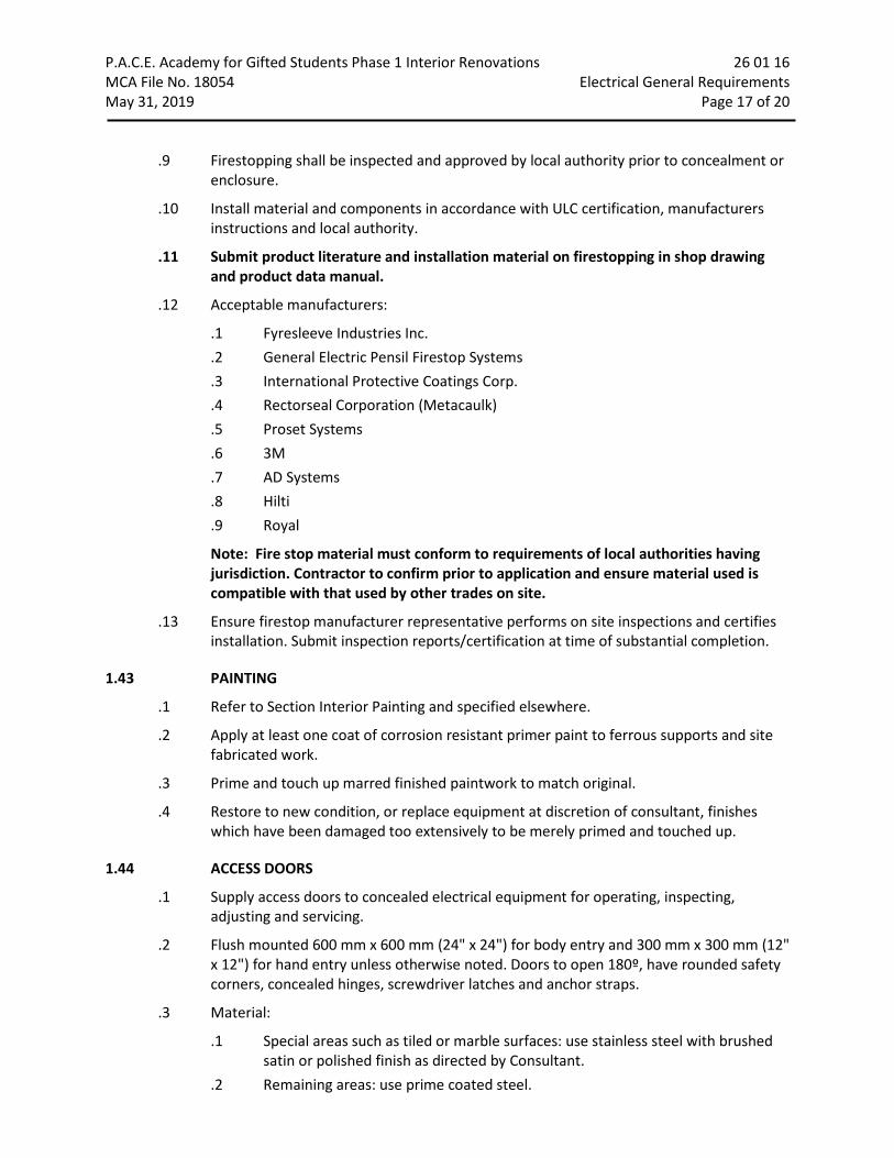
P.A.C.E. Academy for Gifted Students Phase 1 Interior Renovations 26 01 16 MCA File No. 18054 Electrical General Requirements May 31, 2019 Page 17 of 20
.9 Firestopping shall be inspected and approved by local authority prior to concealment or enclosure.
.10 Install material and components in accordance with ULC certification, manufacturers instructions and local authority.
.11 Submit product literature and installation material on firestopping in shop drawing and product data manual.
.12 Acceptable manufacturers:
.1 Fyresleeve Industries Inc.
.2 General Electric Pensil Firestop Systems
.3 International Protective Coatings Corp.
.4 Rectorseal Corporation (Metacaulk)
.5 Proset Systems
.6 3M
.7 AD Systems
.8 Hilti
.9 Royal
Note: Fire stop material must conform to requirements of local authorities having jurisdiction. Contractor to confirm prior to application and ensure material used is compatible with that used by other trades on site.
.13 Ensure firestop manufacturer representative performs on site inspections and certifies installation. Submit inspection reports/certification at time of substantial completion.
1.43 PAINTING
.1 Refer to Section Interior Painting and specified elsewhere.
.2 Apply at least one coat of corrosion resistant primer paint to ferrous supports and site fabricated work.
.3 Prime and touch up marred finished paintwork to match original.
.4 Restore to new condition, or replace equipment at discretion of consultant, finishes which have been damaged too extensively to be merely primed and touched up.
1.44 ACCESS DOORS
.1 Supply access doors to concealed electrical equipment for operating, inspecting, adjusting and servicing.
.2 Flush mounted 600 mm x 600 mm (24" x 24") for body entry and 300 mm x 300 mm (12" x 12") for hand entry unless otherwise noted. Doors to open 180º, have rounded safety corners, concealed hinges, screwdriver latches and anchor straps.
.3 Material:
.1 Special areas such as tiled or marble surfaces: use stainless steel with brushed satin or polished finish as directed by Consultant.
.2 Remaining areas: use prime coated steel.

P.A.C.E. Academy for Gifted Students Phase 1 Interior Renovations 26 01 16 MCA File No. 18054 Electrical General Requirements May 31, 2019 Page 18 of 20
.3 Fire rated areas: provide ULC listed access doors
.4 Installation:
.1 Locate so that concealed items are accessible.
.2 Locate so that hand or body entry (as applicable) is achieved.
.3 Installation is specified in applicable sections.
.5 Acceptable materials:
.1 Le Hage
.2 Zurn
.3 Acudor
.4 Nailor Industries Inc.
1.45 DELIVERY STORAGE & HANDLING
.1 Follow Manufacturer's directions in delivery, storage, and protection, of equipment and materials.
.2 Deliver equipment and material to site and tightly cover and protect against dirt, water, and chemical or mechanical injury, but have readily accessible for inspection. Store items subject to moisture damage (such as controls) in dry, heated space.
1.46 REPAIR, CUTTING, CORING AND RESTORATION
.1 Be responsible for required digging, cutting, and patching incident to work of this Division and make required repairs afterwards to satisfaction of Consultant. Cut carefully to minimize necessity for repairs to existing work. Do not cut beams, columns, or trusses.
.2 Patch and repair walls, floors, ceilings, and roofs with materials of same quality and appearance as adjacent surfaces unless otherwise shown. Surface finishes shall exactly match existing finishes of same materials.
.3 Each Section of this Division shall bear expense of cutting, patching, repairing, and replacing of work of other Sections required because of its fault, error, tardiness, or because of damage done by it.
.4 Cutting, patching, repairing, and replacing pavements, sidewalks, roads, and curbs to permit installation of work of this Division is responsibility of Section installing work.
.5 Slots, cores and openings through floors, walls, ceilings, and roofs shall be provided by this contractor but performed by a trade specializing in this type of work. This Division shall see that they are properly located and do any cutting and patching caused by its neglect to do so.
1.47 EXISTING SYSTEMS
.1 Connections into existing systems to be made at time approved by Consultant. Request written approval of time when connections can be made.
.2 Be responsible for damage to existing plant by this work.
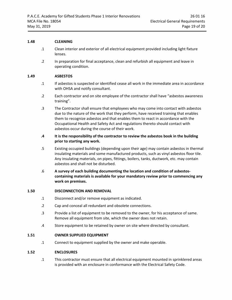
P.A.C.E. Academy for Gifted Students Phase 1 Interior Renovations 26 01 16 MCA File No. 18054 Electrical General Requirements May 31, 2019 Page 19 of 20 1.48 CLEANING
.1 Clean interior and exterior of all electrical equipment provided including light fixture lenses.
.2 In preparation for final acceptance, clean and refurbish all equipment and leave in operating condition.
1.49 ASBESTOS
.1 If asbestos is suspected or identified cease all work in the immediate area in accordance with OHSA and notify consultant.
.2 Each contractor and on site employee of the contractor shall have “asbestos awareness training”.
.3 The Contractor shall ensure that employees who may come into contact with asbestos due to the nature of the work that they perform, have received training that enables them to recognize asbestos and that enables them to react in accordance with the Occupational Health and Safety Act and regulations thereto should contact with asbestos occur during the course of their work.
.4 It is the responsibility of the contractor to review the asbestos book in the building prior to starting any work.
.5 Existing occupied buildings (depending upon their age) may contain asbestos in thermal insulating materials and some manufactured products, such as vinyl asbestos floor tile. Any insulating materials, on pipes, fittings, boilers, tanks, ductwork, etc. may contain asbestos and shall not be disturbed.
.6 A survey of each building documenting the location and condition of asbestos-containing materials is available for your mandatory review prior to commencing any work on premises.
1.50 DISCONNECTION AND REMOVAL
.1 Disconnect and/or remove equipment as indicated.
.2 Cap and conceal all redundant and obsolete connections.
.3 Provide a list of equipment to be removed to the owner, for his acceptance of same. Remove all equipment from site, which the owner does not retain.
.4 Store equipment to be retained by owner on site where directed by consultant.
1.51 OWNER SUPPLIED EQUIPMENT
.1 Connect to equipment supplied by the owner and make operable.
1.52 ENCLOSURES
.1 This contractor must ensure that all electrical equipment mounted in sprinklered areas is provided with an enclosure in conformance with the Electrical Safety Code.

P.A.C.E. Academy for Gifted Students Phase 1 Interior Renovations 26 01 16 MCA File No. 18054 Electrical General Requirements May 31, 2019 Page 20 of 20 1.53 EXISTING CONCRETE SLAB X-RAY/SCANNING
.1 This contractor shall retain the services of a qualified company to provide and X-Ray and/or scan of the existing buried services in walls and/or floors prior to starting any work in the affected area.
.2 Failure to locate existing piping, conduit, rebar etc., shall not relieve this contractor of repair of same prior to installing his service.
.3 This contractor shall be responsible for all repairs and/or replacement of existing services caused by cutting the existing concrete slabs and/or walls.
END OF SECTION

P.A.C.E. Academy for Gifted Students Phase 1 Interior Renovations 26 01 17 MCA File No. 18054 Demolition and Renovation May 31, 2019 Page 1 of 2
Part 1 General
1.1 GENERAL PROVISIONS
.1 Conform to the General Provisions of Division 1 and Electrical General Requirements Section.
.2 This project is one of a retrofit nature in part, and which will require extensive demolition.
.3 Allow for all remedial work in areas indicated on the drawings and as generally defined in the relevant sections of the specifications.
1.2 SCOPE OF WORK
.1 The scope of work is essentially the selected disconnection and/or removal of services and/or equipment, devices etc. as indicated or required to complete the work.
.2 The reference drawings indicate some of the services which shall remain and some may have to be retained through construction and a phased changeover to help construction i.e. electrical service, phone service, winter heat, and temporary construction services i.e. washroom facility. This co-ordination remains the responsibility of the contractors.
Part 2 Products
2.1 GENERAL
.1 This Division is to liaise with the Owners or Consultant for equipment being removed that may be suitable for reuse to that specified or handed over to the owner.
.2 This Division to take full responsibility for any special tools or equipment required to disassemble or remove material from building.
Part 3 Execution
3.1 GENERAL
.1 The general requirements are indicated on the drawings and on the outline specification in Division 1.
.2 The general execution of the demolition is to be carried out in a clean and efficient manner.
.3 Demolition of existing ceiling, walls etc., to facilitate removal of existing services or equipment or installation of new to be kept to a minimum and then restored to match existing.
.4 All openings or holes created by removal of existing electrical systems which are not being reused are to be patched with the same material surrounding surfaces.
.5 All new holes and openings to facilitate electrical systems are to be patched to match surrounding surfaces.
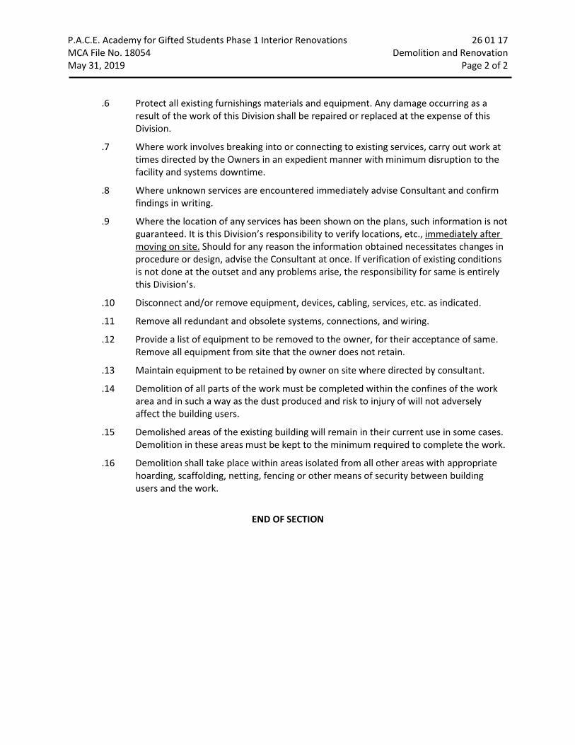
P.A.C.E. Academy for Gifted Students Phase 1 Interior Renovations 26 01 17 MCA File No. 18054 Demolition and Renovation May 31, 2019 Page 2 of 2
.6 Protect all existing furnishings materials and equipment. Any damage occurring as a result of the work of this Division shall be repaired or replaced at the expense of this Division.
.7 Where work involves breaking into or connecting to existing services, carry out work at times directed by the Owners in an expedient manner with minimum disruption to the facility and systems downtime.
.8 Where unknown services are encountered immediately advise Consultant and confirm findings in writing.
.9 Where the location of any services has been shown on the plans, such information is not guaranteed. It is this Division’s responsibility to verify locations, etc., immediately after moving on site. Should for any reason the information obtained necessitates changes in procedure or design, advise the Consultant at once. If verification of existing conditions is not done at the outset and any problems arise, the responsibility for same is entirely this Division’s.
.10 Disconnect and/or remove equipment, devices, cabling, services, etc. as indicated.
.11 Remove all redundant and obsolete systems, connections, and wiring.
.12 Provide a list of equipment to be removed to the owner, for their acceptance of same. Remove all equipment from site that the owner does not retain.
.13 Maintain equipment to be retained by owner on site where directed by consultant.
.14 Demolition of all parts of the work must be completed within the confines of the work area and in such a way as the dust produced and risk to injury of will not adversely affect the building users.
.15 Demolished areas of the existing building will remain in their current use in some cases. Demolition in these areas must be kept to the minimum required to complete the work.
.16 Demolition shall take place within areas isolated from all other areas with appropriate hoarding, scaffolding, netting, fencing or other means of security between building users and the work.
END OF SECTION

P.A.C.E. Academy for Gifted Students Phase 1 Interior Renovations 26 05 19 MCA File No. 18054 Wires and Cables May 31, 2019 Page 1 of 2
Part 1 General
1.1 REFERENCES
.1 CSA C22.2 No.0.3-92, Test Methods for Electrical Wires and Cables.
1.2 PRODUCT DATA
.1 Submit product data in accordance with Electrical General Requirements Section.
Part 2 Products
2.1 BUILDING WIRES
.1 Conductors: stranded for 10 AWG and larger.
.2 Minimum size: 12 AWG.
.3 Copper conductors: size as indicated, with 600 V insulation of chemically cross-linked thermosetting polyethylene material 90°C (194ºF) rated T90 for indoor above grade installations and RW90 for below grade installations.
2.2 ARMOURED CABLES
.1 Conductors: insulated, copper minimum size as indicated above.
.2 Type: AC90 (minimum size 12 AWG).
.3 Armour: interlocking type fabricated from aluminum strip.
.4 Connectors must be suitable for installed environment and approved for use with armoured cable.
Part 3 Execution
3.1 INSTALLATION OF BUILDING WIRES
.1 Install wiring from source to load through raceways as specified.
.2 Provide separate neutral conductors for all lighting circuits and circuits originating from surge protected panels. Size raceways accordingly.
3.2 INSTALLATION OF ARMOURED CABLES
.1 Group cables wherever possible.
.2 Terminate cables in accordance with Wire and Box Connectors - 0 - 1000 V Section.

P.A.C.E. Academy for Gifted Students Phase 1 Interior Renovations 26 05 19 MCA File No. 18054 Wires and Cables May 31, 2019 Page 2 of 2
.3 These cables are to be installed in concealed locations only. These concealed locations are considered to be stud walls and “drops” to stud walls, lighting fixtures, and ceiling mounted devices.
.4 These “drops’ shall not be permitted to exceed 2.4 m (8'-0"). To limit these “drops” to lengths noted above provide additional branch wiring in conduit.
END OF SECTION
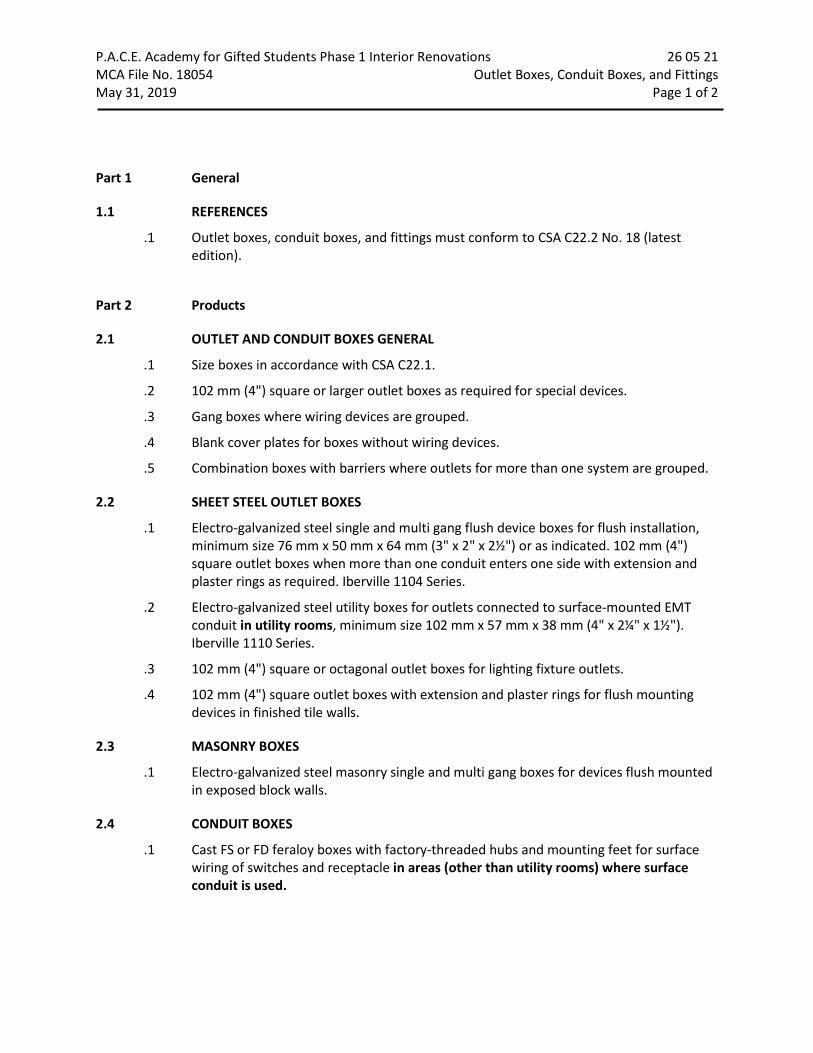
P.A.C.E. Academy for Gifted Students Phase 1 Interior Renovations 26 05 21 MCA File No. 18054 Outlet Boxes, Conduit Boxes, and Fittings May 31, 2019 Page 1 of 2
Part 1 General
1.1 REFERENCES
.1 Outlet boxes, conduit boxes, and fittings must conform to CSA C22.2 No. 18 (latest edition).
Part 2 Products
2.1 OUTLET AND CONDUIT BOXES GENERAL
.1 Size boxes in accordance with CSA C22.1.
.2 102 mm (4") square or larger outlet boxes as required for special devices.
.3 Gang boxes where wiring devices are grouped.
.4 Blank cover plates for boxes without wiring devices.
.5 Combination boxes with barriers where outlets for more than one system are grouped.
2.2 SHEET STEEL OUTLET BOXES
.1 Electro-galvanized steel single and multi gang flush device boxes for flush installation, minimum size 76 mm x 50 mm x 64 mm (3" x 2" x 2½") or as indicated. 102 mm (4") square outlet boxes when more than one conduit enters one side with extension and plaster rings as required. Iberville 1104 Series.
.2 Electro-galvanized steel utility boxes for outlets connected to surface-mounted EMT conduit in utility rooms, minimum size 102 mm x 57 mm x 38 mm (4" x 2¼" x 1½"). Iberville 1110 Series.
.3 102 mm (4") square or octagonal outlet boxes for lighting fixture outlets.
.4 102 mm (4") square outlet boxes with extension and plaster rings for flush mounting devices in finished tile walls.
2.3 MASONRY BOXES
.1 Electro-galvanized steel masonry single and multi gang boxes for devices flush mounted in exposed block walls.
2.4 CONDUIT BOXES
.1 Cast FS or FD feraloy boxes with factory-threaded hubs and mounting feet for surface wiring of switches and receptacle in areas (other than utility rooms) where surface conduit is used.

P.A.C.E. Academy for Gifted Students Phase 1 Interior Renovations 26 05 21 MCA File No. 18054 Outlet Boxes, Conduit Boxes, and Fittings May 31, 2019 Page 2 of 2 2.5 FITTINGS- GENERAL
.1 Bushing and connectors with nylon insulated throats.
.2 Knock-out fillers to prevent entry of debris.
.3 Conduit outlet bodies for conduit up to 32 mm (1- 1/4") and pull boxes for larger conduits.
.4 Double locknuts and insulated bushings on sheet metal boxes.
Part 3 Execution
3.1 INSTALLATION
.1 Support boxes independently of connecting conduits.
.2 Fill boxes with paper, sponges or foam or similar approved material to prevent entry of debris during construction. Remove upon completion of work.
.3 For flush installations mount outlets flush with finished wall using plaster rings to permit wall finish to come within 6 mm (1/4") of opening.
.4 Provide correct size of openings in boxes for conduit, mineral insulated and armoured cable connections. Reducing washers are not allowed.
.5 Outlets if unwired are to be provided with blank coverplates to suit related sections of this specification.
END OF SECTION

P.A.C.E. Academy for Gifted Students Phase 1 Interior Renovations 26 05 22 MCA File No. 18054 Wire and Box Connectors – 0 – 1000 V May 31, 2019 Page 1 of 1
Part 1 General
1.1 REFERENCES
.1 CSA C22.2 No.65-1956(R1965) Wire Connectors.
Part 2 Products
2.1 MATERIALS
.1 Pressure type wire connectors: with current carrying parts of copper sized to fit copper conductors as indicated.
.2 Fixture type splicing connectors: with current carrying parts of copper sized to fit copper conductors 10 AWG or less.
.3 Clamps or connectors for armoured cable, mineral insulated cable, and flexible conduit, as required.
Part 3 Execution
3.1 INSTALLATION
.1 Remove insulation carefully from ends of conductors and:
.1 Apply coat of zinc joint compound on aluminum conductors prior to installation of connectors.
.2 Install mechanical pressure type connectors and tighten screws with appropriate compression tool recommended by manufacturer. Installation shall meet secureness tests in accordance with CSA C22.2 No.65.
.3 Install fixture type connectors and tighten. Replace insulating cap.
END OF SECTION
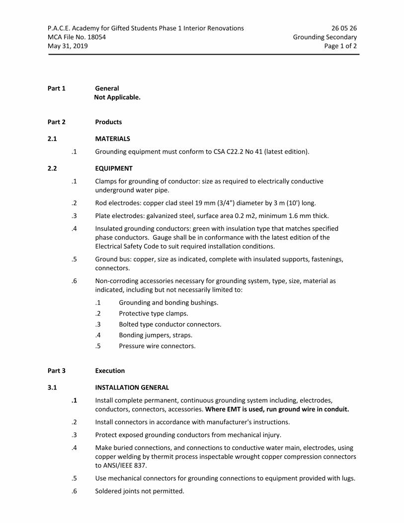
P.A.C.E. Academy for Gifted Students Phase 1 Interior Renovations 26 05 26 MCA File No. 18054 Grounding Secondary May 31, 2019 Page 1 of 2
Part 1 General Not Applicable.
Part 2 Products
2.1 MATERIALS
.1 Grounding equipment must conform to CSA C22.2 No 41 (latest edition).
2.2 EQUIPMENT
.1 Clamps for grounding of conductor: size as required to electrically conductive underground water pipe.
.2 Rod electrodes: copper clad steel 19 mm (3/4") diameter by 3 m (10') long.
.3 Plate electrodes: galvanized steel, surface area 0.2 m2, minimum 1.6 mm thick.
.4 Insulated grounding conductors: green with insulation type that matches specified phase conductors. Gauge shall be in conformance with the latest edition of the Electrical Safety Code to suit required installation conditions.
.5 Ground bus: copper, size as indicated, complete with insulated supports, fastenings, connectors.
.6 Non-corroding accessories necessary for grounding system, type, size, material as indicated, including but not necessarily limited to:
.1 Grounding and bonding bushings.
.2 Protective type clamps.
.3 Bolted type conductor connectors.
.4 Bonding jumpers, straps.
.5 Pressure wire connectors.
Part 3 Execution
3.1 INSTALLATION GENERAL
.1 Install complete permanent, continuous grounding system including, electrodes, conductors, connectors, accessories. Where EMT is used, run ground wire in conduit.
.2 Install connectors in accordance with manufacturer's instructions.
.3 Protect exposed grounding conductors from mechanical injury.
.4 Make buried connections, and connections to conductive water main, electrodes, using copper welding by thermit process inspectable wrought copper compression connectors to ANSI/IEEE 837.
.5 Use mechanical connectors for grounding connections to equipment provided with lugs.
.6 Soldered joints not permitted.

P.A.C.E. Academy for Gifted Students Phase 1 Interior Renovations 26 05 26 MCA File No. 18054 Grounding Secondary May 31, 2019 Page 2 of 2
.7 Install bonding wire for flexible conduit, connected at both ends to grounding bushing, solderless lug, clamp or cup washer and screw. Neatly cleat bonding wire to exterior of flexible conduit.
.8 Ground pad mounted transformers as detailed on the drawings.
3.2 EQUIPMENT GROUNDING
.1 Install grounding connections to typical equipment included in, but not necessarily limited to following list. Service equipment, frames of motors, starters, control panels, and distribution panels.
3.3 COMMUNICATION SYSTEMS
.1 Install grounding connections for telephone, sound, fire alarm, computer network systems as follows:
.1 Telephones: make telephone grounding system in accordance with telephone company's requirements.
.2 Sound, fire alarm, computer network systems as indicated.
3.4 FIELD QUALITY CONTROL
.1 Perform tests in accordance with Electrical General Requirements Section.
.2 Perform ground continuity and resistance tests using method appropriate to site conditions and to approval of local authority having jurisdiction over installation.
.3 Perform tests before energizing electrical system.
END OF SECTION

P.A.C.E. Academy for Gifted Students Phase 1 Interior Renovations 26 05 33 MCA File No. 18054 Conduits, Conduit Fastenings and Conduit Fittings May 31, 2019 Page 1 of 3
Part 1 General
1.1 REFERENCES
.1 Canadian Standards Association (CSA)
.1 CAN/CSA C22.2 No.18-92, Outlet Boxes, Conduit Boxes, and Fittings.
.2 CSA C22.2 No.56-1977(R1977), Flexible Metal Conduit and Liquid-Tight Flexible Metal Conduit.
.3 CSA C22.2 No.83-M1985(R1992), Electrical Metallic Tubing.
.4 CSA C22.2 No.211.2-M1984(R1992), Rigid PVC (Unplasticized) Conduit.
.5 CAN/CSA C22.2 No.227.3-M91, Flexible Nonmetallic Tubing.
Part 2 Products
2.1 CONDUITS
.1 Electrical metallic tubing (EMT) with couplings: to CSA C22.2 No.83.
.2 Rigid PVC conduit: to CSA C22.2 No.211.2.
.3 Flexible metal conduit: to CSA C22.2 No.56, aluminum and liquid-tight flexible metal.
.4 Flexible PVC conduit: to CAN/CSA C22.2 No.227.3, ENT.
2.2 CONDUIT FASTENINGS
.1 One hole steel straps to secure surface conduits 53 mm (2") and smaller. Two hole steel straps for conduits larger than 53 mm (2").
.2 Beam clamps to secure conduits to exposed steel work.
.3 Channel type supports for two or more conduits at 1.5 m (5'0") oc.
.4 Threaded rods, 6 mm (1/4") diameter, to support suspended channels.
2.3 CONDUIT FITTINGS
.1 EMT fittings shall be set screw style (zinc alloy).
.2 Flexible metal conduit fittings shall be screw-in type.
.3 Liquid type flexible metal conduit fittings shall be sealtite type.
.4 PVC fittings shall be PVC type complete with PVC adaptors at all boxes.
.5 Coating: same as conduit.
.6 Factory "ells" where 90° bends are required for 27 mm (1") and larger conduits.
.7 Where bushings are noted to be provided they must be “screwed” type fastened to a conduit connector. Push-fit or glued in place bushings will NOT be accepted.
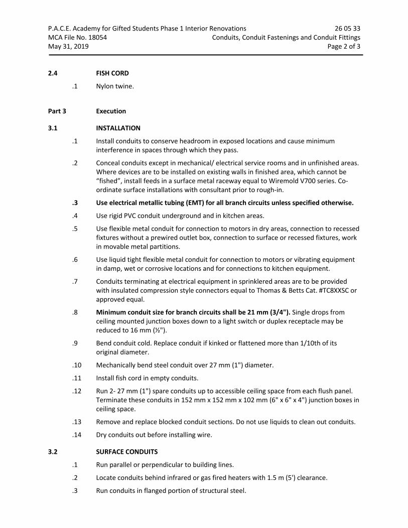
P.A.C.E. Academy for Gifted Students Phase 1 Interior Renovations 26 05 33 MCA File No. 18054 Conduits, Conduit Fastenings and Conduit Fittings May 31, 2019 Page 2 of 3 2.4 FISH CORD
.1 Nylon twine.
Part 3 Execution
3.1 INSTALLATION
.1 Install conduits to conserve headroom in exposed locations and cause minimum interference in spaces through which they pass.
.2 Conceal conduits except in mechanical/ electrical service rooms and in unfinished areas. Where devices are to be installed on existing walls in finished area, which cannot be “fished”, install feeds in a surface metal raceway equal to Wiremold V700 series. Co-ordinate surface installations with consultant prior to rough-in.
.3 Use electrical metallic tubing (EMT) for all branch circuits unless specified otherwise.
.4 Use rigid PVC conduit underground and in kitchen areas.
.5 Use flexible metal conduit for connection to motors in dry areas, connection to recessed fixtures without a prewired outlet box, connection to surface or recessed fixtures, work in movable metal partitions.
.6 Use liquid tight flexible metal conduit for connection to motors or vibrating equipment in damp, wet or corrosive locations and for connections to kitchen equipment.
.7 Conduits terminating at electrical equipment in sprinklered areas are to be provided with insulated compression style connectors equal to Thomas & Betts Cat. #TC8XXSC or approved equal.
.8 Minimum conduit size for branch circuits shall be 21 mm (3/4"). Single drops from ceiling mounted junction boxes down to a light switch or duplex receptacle may be reduced to 16 mm (½").
.9 Bend conduit cold. Replace conduit if kinked or flattened more than 1/10th of its original diameter.
.10 Mechanically bend steel conduit over 27 mm (1") diameter.
.11 Install fish cord in empty conduits.
.12 Run 2- 27 mm (1") spare conduits up to accessible ceiling space from each flush panel. Terminate these conduits in 152 mm x 152 mm x 102 mm (6" x 6" x 4") junction boxes in ceiling space.
.13 Remove and replace blocked conduit sections. Do not use liquids to clean out conduits.
.14 Dry conduits out before installing wire.
3.2 SURFACE CONDUITS
.1 Run parallel or perpendicular to building lines.
.2 Locate conduits behind infrared or gas fired heaters with 1.5 m (5') clearance.
.3 Run conduits in flanged portion of structural steel.
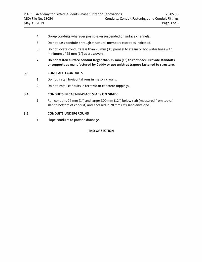
P.A.C.E. Academy for Gifted Students Phase 1 Interior Renovations 26 05 33 MCA File No. 18054 Conduits, Conduit Fastenings and Conduit Fittings May 31, 2019 Page 3 of 3
.4 Group conduits wherever possible on suspended or surface channels.
.5 Do not pass conduits through structural members except as indicated.
.6 Do not locate conduits less than 75 mm (3") parallel to steam or hot water lines with minimum of 25 mm (1") at crossovers.
.7 Do not fasten surface conduit larger than 25 mm (1") to roof deck. Provide standoffs or supports as manufactured by Caddy or use unistrut trapeze fastened to structure.
3.3 CONCEALED CONDUITS
.1 Do not install horizontal runs in masonry walls.
.2 Do not install conduits in terrazzo or concrete toppings.
3.4 CONDUITS IN CAST-IN-PLACE SLABS ON GRADE
.1 Run conduits 27 mm (1") and larger 300 mm (12") below slab (measured from top of slab to bottom of conduit) and encased in 78 mm (3") sand envelope.
3.5 CONDUITS UNDERGROUND
.1 Slope conduits to provide drainage.
END OF SECTION

P.A.C.E. Academy for Gifted Students Phase 1 Interior Renovations 26 05 75 MCA File No. 18054 Auxiliary Systems May 31, 2019 Page 1 of 5
Part 1 General
1.1 SHOP DRAWINGS
.1 Submit shop drawings for each system in Conformance with The Electrical General Requirements Section.
1.2 PRODUCT/MAINTENANCE DATA
.1 Submit product/maintenance data for each system for inclusion in maintenance manual conforming to The General Electrical Requirements Section.
1.3 SCOPE
.1 The scope of this Section will include the following systems.
.1 Surface mounted raceway.
.2 Cable management hangers.
.3 Telecommunication network system rough-in.
.4 Miscellaneous clocks.
.5 Occupancy sensors.
.6 Hand dryers.
Part 2 Products
2.1 SURFACE MOUNTED RACEWAY
.1 The two compartment surface raceway shall be complete with the following features:
.1 Surface non-metallic raceway is to be utilized in dry interior locations only as covered in Article 352 Part B of the National Electrical Code, as adopted by the National Fire Protection Association and as approved by the American National Standards Institute.
.2 The surface non-metallic raceway system specified herein for branch circuit wiring and/or data network, voice, video and other low-voltage wiring shall be the T70 System as manufactured by Panduit (no equals).
.3 The raceway and all system components must be UL Listed and exhibit non-flammable self-extinguishing characteristics tested to comparable specifications of UL94V-0. The raceway base and cover shall be manufactured by rigid compound, available in ivory or white colours (Architect Selection).
.4 The raceway shall be a two-piece design with a base and a snap-on cover. Total width shall be 133 mm (5.1/4”) by 44.5 mm (1.3/4”) deep with an approximate thickness of 2.4 mm (1/12”). The base and cover shall be available in 2.4 m (8’) lengths. The raceway shall be available with two multiple wiring channels formed by integral barriers in the base.
.5 The cover shall span the entire width of the base concealing all of the wiring channels.

P.A.C.E. Academy for Gifted Students Phase 1 Interior Renovations 26 05 75 MCA File No. 18054 Auxiliary Systems May 31, 2019 Page 2 of 5
.6 A full compliment of fittings must be available including, but not limited to flat, internal and external elbows, tees entrance fittings, cover clips and end caps. They shall be manufactured of a rigid PVC compound. The fittings shall have a matte texture, in ivory or white colours to match the base and cover. They shall overlap the cover and base to hide uneven cuts. All fittings shall be supplied with a base where applicable to eliminate mitring. A transition fitting shall be available to adapt to other Wiremold series raceways.
.7 Device brackets shall be available for mounting standard devices in-line with the raceway. Faceplates shall match and fit flush in the device plate. They shall be manufactured of rigid PVC compound. They shall be ivory or white colours to match raceway base cover (Architect selection). Contractor is to provide devices as noted.
.8 The raceway manufacturer will provide a complete line of connectivity outlets and modular inserts for UTP (including Category 5e and 6), STP (150 ohm) Fibre Optic, Coaxial and other cabling types with face plates and bezels to facilitate mounting. The electrical contractor is to provide adapter plates for faceplates to be provided by the voice/data sub-contractor. The recommended plate is a Deco adapter 3-port plate style, confirm with voice/data sub-contractor.
2.2 CABLE MANAGEMENT HANGERS
.1 Hangers where noted are to be complete with the following features:
.1 Approximately 150 mm (6”) high by 80 mm (3 1/4”) protrusion.
.2 Constructed from 5 mm (3/16”) x 20 mm (3/4”) flat steel bar and formed to resemble the letter “G”.
.3 Seven 6 mm (¼”) diameter mounting holes are to be provided around the hanger perimeter.
.4 Matte black finish.
.5 Suitable for wall or suspended mounting.
.6 Acceptable Manufacturers: .1 EMF Cat. #H-533-S
.7 Manufacturer Contact: Electron Metal Fabricators Inc. 2160 Dagenais Boulevard West Laval, Quebec H7L 5X9 Phone: 450-625-8064 or 1-800-267-8064 Fax: 450-625-8004
.8 Acceptable Alternate: Wiremold Cat. #GH030406 Mono System Cat. # The Hook H-433 Cablofil Cat. #CSGH-3-4-6

P.A.C.E. Academy for Gifted Students Phase 1 Interior Renovations 26 05 75 MCA File No. 18054 Auxiliary Systems May 31, 2019 Page 3 of 5 2.3 TELECOMMUNICATION NETWORK SYSTEM ROUGH-IN
.1 Outlets where noted shall be single gang flush mounted in wall or surface raceways.
.2 Outlets if unwired are to be provided with blank coverplates to suit related sections of this specification.
.3 Provide a #6 insulated green ground conductor from main service ground to voice equipment backboard located on drawings.
.4 Refer to Telecommunication Network Installations section for additional Telecommunication network installation requirements.
2.4 OCCUPANCY SENSORS
.1 Where noted on drawings the wall mounted (passive technology) occupancy sensor used in storage and service rooms shall be:
.1 Hubbell Cat. # AP1277XIN (colour by Architect).
.2 Wattstopper Cat. #PW-100-VOLT-X (colour by Architect).
.3 Leviton Cat. #ODS-15-ID-VOLT-X (colour by Architect).
.4 Sensor switch Cat. #WSD-VOLT-X (colour by architect).
.5 Eaton NeoSwitch Cat #VNW-P-1001-MV-X (colour by architect).
.2 Where noted on the drawings, the wall mounted switch style occupancy sensor used in Administrative Offices and Seminar/Meeting Rooms shall be a dual technology switch with either single or double relay (circuit) as noted on the drawings. Colour to suit architect.
Note: For dual relay switches, program the sensor for 15 minute off delay, enabled walk-thru, audible alert enabled, relay 1 on mode: auto on, relay 2 on mode: manual on.
.1 Single relay (circuit): Wattstopper Cat. #DW-100
.2 Dual relay (circuit): Wattstopper Cat. #DW-200
.3 Approved equal: .1 Hubbell. .2 Leviton. .3 Sensor switch. .4 Eaton
.3 Provide other occupancy sensors to suit the detail on the drawings.
.4 All sensors shall be set to 5 minutes “delay to off” unless otherwise directed.

P.A.C.E. Academy for Gifted Students Phase 1 Interior Renovations 26 05 75 MCA File No. 18054 Auxiliary Systems May 31, 2019 Page 4 of 5 2.5 HAND DRYERS
.1 Hand dryers where noted on the drawings are to be supplied and installed by this Division with the following features:
.1 Surface mounting.
.2 Fixed nozzle.
.3 White finish with automatic activation.
.4 Rating of 950 W (8.3 A) at 120 V.
.5 World Dryer Cat. # Q-974A.
.6 Approved alternate: .1 NOVA 4-0412
Part 3 Execution
3.1 SURFACE MOUNTED RACEWAY
.1 Raceway is to be supplied and installed c/w all necessary fittings, hardware and device brackets for configuration as noted in the drawings for a complete functional installation.
.2 Install conduit system, wiring and devices as indicated.
.3 Ensure raceway is installed as per manufacturer recommendations.
.4 Where the raceway ends at a wall install end cap.
3.2 CABLE MANAGEMENT HANGERS
.1 Install hangers as per details in configuration noted.
.2 Prior to installation co-ordinate location with other services within the ceiling space.
.3 Co-ordinate with noted sub-contractors to install cables noted to be utilizing these hangers. Cables are to be installed such that the maximum sag between hangers does not exceed 25 mm (1"). This electrical contractor is to coordinate.
.4 Attaching cable to any t-bar support rods is not acceptable.
3.3 TELECOMMUNICATION NETWORK SYSTEM ROUGH-IN
.1 Provide backboard as noted complete with ground connection to main service ground.
.2 Conduits terminated into ceiling spaces must be within 3m (10') of zone conduits (if applicable).
.3 Ensure specified zone conduits are installed back to service backboard.
.4 Outlets are to be installed complete with 25 mm (1") conduit to corridor ceiling space or nearest zone conduit (if applicable).
.5 Provide insulated bushings on all conduits terminated in ceiling space.
.6 Refer to Telecommunication Network Installations Section for additional Telecommunication network installation requirements.

P.A.C.E. Academy for Gifted Students Phase 1 Interior Renovations 26 05 75 MCA File No. 18054 Auxiliary Systems May 31, 2019 Page 5 of 5 3.4 OCCUPANCY SENSORS
.1 Install power packs in accessible maintenance areas.
.2 Provide access doors if power packs are installed above drywall ceilings.
.3 It shall be the contractor’s responsibility to locate and aim sensory in the correct location required for complete and proper coverage within the range of coverage as per the manufacturer’s recommendations. The locations and quantities of sensors shown on the drawings are diagrammatic and indicate only the rooms which are to be provided with sensors. The contractor shall provide additional sensors if required to properly and completely cover the respective rooms.
.4 It is the contractor’s responsibility to arrange a pre-installation meeting with the manufacturer’s factory authorized representative, at the facility, to verify placement to sensors and installation criteria.
.5 The contractor shall also provide the on-site training necessary to familiarize the owner’s personnel with the operation, use, adjustment and problem solving diagnosis of the occupancy sensing devices systems.
.6 Upon completion of the installation, the system shall be completely commissioned by the manufacturer’s factory authorized technician who will verify all adjustments and sensor placement to ensure a trouble-free occupancy-based lighting control. Submit commissioning report with closeout documents.
3.5 HAND DRYERS
.1 Install and connect hand dryers in conformance with manufacturer’s recommendations.
.2 Hand dryers are to be mounted at a height to suit age of expected users’. Unless otherwise noted confirm height with manufacturer, owner, Architect, and/or consultant prior to rough in.
.3 Once installed this contractor is to caulk the joint between dryer and wall surface with a bead of white silicone.
END OF SECTION

P.A.C.E. Academy for Gifted Students Phase 1 Interior Renovations 26 27 26 MCA File No. 18054 Wiring Devices May 31, 2019 Page 1 of 4
Part 1 General
1.1 SHOP DRAWINGS AND PRODUCT DATA
.1 Submit shop drawings and product data in accordance with Electrical General Requirements Section.
Part 2 Products
2.1 SWITCHES
.1 General purpose AC switches must conform to CSA C22.2 No. 111 (latest edition).
.2 15 or 20 A, 120 V, single pole, double pole, three-way, four-way, keyed, or motor rated switches complete with pilot light.
.3 Manually-operated general purpose ac switches with following features:
.1 Terminal holes approved for No. 10 AWG wire.
.2 Silver alloy contacts.
.3 Urea or melamine molding for parts subject to carbon tracking.
.4 Suitable for back and side wiring.
.5 Toggle style (architect to select colour).
.4 Toggle operated fully rated for tungsten filament and fluorescent lamps, and up to 80% of rated capacity of motor loads.
.5 Switches of one manufacturer throughout project.
.6 Acceptable materials:
single pole: Hubbell Cat # HBL1201 Series
three way: Hubbell Cat # HBL1203 Series
four way: Hubbell Cat # HBL1204 Series
Keyed: Hubbell Cat. #HBL1221 Series complete with 2 keys per switch
(Keys): Hubbell Cat. #HBL1209
Motor rated: Hubbell Cat. #HBL1221PL c/w pilot light (20 A):
.7 Acceptable alternate manufacturers include:
.1 Pass & Seymour
.2 Leviton.

P.A.C.E. Academy for Gifted Students Phase 1 Interior Renovations 26 27 26 MCA File No. 18054 Wiring Devices May 31, 2019 Page 2 of 4 2.2 RECEPTACLES
.1 Receptacles, plugs, and other similar wiring devices must conform to CSA 22.2 No 42 (latest edition).
.2 Duplex receptacles, CSA type 5-15 R, 125 V, 15 A, U ground, with following features (20A where noted):
.1 Urea molded housing (Colour by architect).
.2 Suitable for No. 10 AWG for back and side wiring.
.3 Break-off links for use as split receptacles.
.4 Eight back wired entrances, four side wiring screws.
.5 Triple wipe contacts and rivetted grounding contacts.
.3 Other receptacles with ampacity and voltage as indicated.
.4 Receptacles of one manufacturer throughout project.
.5 Acceptable materials:
Standard duplex receptacle Hubbell Cat # HBL5252CN Surge duplex receptacle Hubbell Cat. #HBL5260SA complete with
Decora style coverplate to suit specification below
Ground fault protected T-slot receptacles
Hubbell Cat. # GF20L A complete with Decora style coverplate to suit specification below
T-slot receptacles Hubbell Cat. #HBL5352 Dryer receptacle Hubbell Cat # HBL9430A Range receptacle Hubbell Cat # HBL9450A Tamper resistant receptacle Hubbell Cat # BR15TR Tamper resistant T-slot receptacle Hubbell Cat. #BR20TR Tamper resistant ground fault protected receptacle
Hubbell Cat. #GFTR15
Tamper resistant ground fault protected T-slot receptacle
Hubbell Cat. #GFTR20 complete with Decora style coverplate to suit specification below
Tamper resistant duplex receptacle complete with dual USB ports
Hubbell Cat. #USB15XXX
USB charger duplex receptacles Hubbell Cat. # USB15X2 XX complete with Decora style coverplate to suit specification below.
USB charger T-slot receptacles Hubbell Cat. #USB20X2 XX complete with Decora style coverplate to suit specification below.
Decora style duplex receptacle Hubbell Cat. #HBL2152 complete with Decora style coverplate to suit specification below
Decora T-slot receptacle Hubbell Cat. # HBL2162 complete with Decora style coverplate to suit specification below.
Decora tamper resistant receptacle Hubbell Cat. #DR15TR c/w Decora style coverplate to suit specification below

P.A.C.E. Academy for Gifted Students Phase 1 Interior Renovations 26 27 26 MCA File No. 18054 Wiring Devices May 31, 2019 Page 3 of 4
Decora tamper resistant T-slot receptacle
Hubbell Cat. #DR20TR c/w Decora style coverplate to suit specification below
Automatically Controlled Receptacles (Green)
Hubbell Cat. #BR15C2GN(Green)
Automatically Controlled Tamper Resistant Receptacles (Green)
Hubbell Cat. #BR15C2GNTR
.6 Acceptable alternate manufacturers include:
.1 Pass & Seymour
.2 Leviton
2.3 COVER PLATES
.1 Cover plates from one manufacturer throughout project.
.2 Sheet steel utility box cover for wiring devices installed in surface-mounted utility boxes.
.3 Stainless steel, brushed, 1 mm (1/32") thick cover plates for wiring devices mounted in flush-mounted outlet box.
.4 Sheet metal cover plates for wiring devices mounted in surface-mounted FS or FD type conduit boxes.
.5 Weatherproof cover plates complete with gaskets and “heavy-duty in use” covers in conformance with the Electrical Safety Authority. Provide product equal to Intermatic Cat. #WP5100C.
Part 3 Execution
3.1 INSTALLATION
.1 Switches:
.1 Install single throw switches with handle in "UP" position when switch closed.
.2 Install switches in gang type outlet box when more than one switch is required in one location.
.3 Mount toggle switches at height specified in Electrical General Requirements Section or as indicated.
.2 Receptacles:
.1 Install receptacles in gang type outlet box when more than one receptacle is required in one location.
.2 Mount receptacles at height specified in Electrical General Requirements Section or as indicated.
.3 Where split receptacle has one portion switched mount vertically and switch upper portion.

P.A.C.E. Academy for Gifted Students Phase 1 Interior Renovations 26 27 26 MCA File No. 18054 Wiring Devices May 31, 2019 Page 4 of 4
.3 Cover plates:
.1 Protect stainless steel cover plate finish with paper or plastic film until painting and other work is finished.
.2 Install suitable common cover plates where wiring devices are grouped.
.3 Do not use cover plates meant for flush outlet boxes on surface-mounted boxes.
END OF SECTION

P.A.C.E. Academy for Gifted Students Phase 1 Interior Renovations 26 51 13 MCA File No. 18054 Lighting Equipment May 31, 2019 Page 1 of 6
Part 1 General
1.1 REFERENCES
.1 American National Standards Institute (ANSI)
.2 American National Standards Institute/Institute of Electrical and Electronics Engineers (ANSI/IEEE)
.1 ANSI/IEEE C62.41- 1991, Recommended Practices for Surge Voltages in Low-Voltage AC Power Circuits.
.3 American Society for Testing and Materials (ASTM)
.1 ASTM F1137- 88 (1993), Specification for Phosphate/Oil and Phosphate/Organic Corrosion Protective Coatings for Fasteners.
.4 United States of America, Federal Communications Commission (FCC)
.1 FCC (CFR47) EM and RF Interference Suppression.
.5 IESNA LM-79-08, IES Electrical Method for the Electrical and Photometric Measurements of Solid State Lighting Products.
1.2 SHOP DRAWINGS AND PRODUCT DATA
.1 Submit shop drawings in accordance with Electrical General Requirements Section for all light fixtures supplied under this contract.
.2 Submit complete photometric data prepared by independent testing laboratory for luminaires where specified, for review by Consultant.
.3 Photometric data to include: VCP Table spacing criterion.
1.3 SCOPE
.1 This contractor is responsible to supply and install all lighting fixtures as scheduled and/or indicated including lamp and those accessories required for a complete lighting system. This contractor must coordinate lighting installations with all other Divisions of this project.
.2 All fixtures must be CSA approved or approved at this contractor’s expense by the Special Inspection Division of the Electrical Safety Authority.
1.4 GUARANTEE
.1 Guarantees shall be as follows from date of substantial completion.
.1 LED fixtures, and driver: 5 years.
.2 The labour required to replace these drivers must be included in the above guarantee.

P.A.C.E. Academy for Gifted Students Phase 1 Interior Renovations 26 51 13 MCA File No. 18054 Lighting Equipment May 31, 2019 Page 2 of 6 Part 2 Products
2.1 FIXTURE CONSTRUCTION
.1 Fixtures must be constructed of 20 gauge (minimum) cold rolled steel. All metal edges require smooth finish.
.2 Light leaks must be prevented by providing gasketting, stops, and barriers.
.3 Fixtures must be finished in high reflective baked white enamel. This surface must have a reflectance of not less than 85%.
2.2 FIXTURE LENS
.1 Unless otherwise noted fixture lenses shall be as follows:
.1 Lens thickness: 3.2 mm (1/8").
.2 Material: injection moulded clear prismatic virgin acrylic.
.3 Frame: hinged, latched, steel.
2.3 LED FIXTURES
.1 Fixture LED’s must be tested in conformance with IESNA LM80 standard.
.2 LED’s must be selected using a binning algorithm to ensure colour and lumen output of a given fixture are consistent, as well as meet or surpass ANSI C78.377 specification for the rated lifetime of the fixture. Colour accuracy between products must be within a 2-step MacAdam ellipse.
.3 Luminaires must be tested to IESNA LM79 by an independent approved laboratory.
.4 Luminaires must be tested prior to shipping.
.5 Luminaires must be ULC certified and approved for use in Canada.
.6 Fixtures must maintain a minimum of 90% of their initial light output for 60,000 hours. Submit test results upon request.
.7 Lumen values indicated for fixtures in the project documents are to be considered as “absolute” or “delivered” values.
.8 Other than for specialty fixtures, and unless otherwise indicated, the maximum driver current is to be 750 mA.
2.4 STANDARD EXIT LIGHTING UNITS
.1 Exit lighting units must conform to CSA C860, CSA 22.2 No. 141 (latest edition).
.2 Housing: extruded aluminum housing, white finish.
.3 Face and back plates: extruded aluminum.
.4 Lamps: 2W LED.
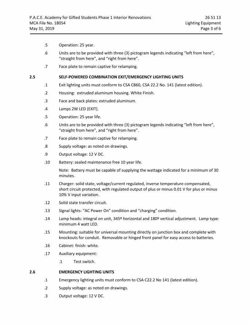
P.A.C.E. Academy for Gifted Students Phase 1 Interior Renovations 26 51 13 MCA File No. 18054 Lighting Equipment May 31, 2019 Page 3 of 6
.5 Operation: 25 year.
.6 Units are to be provided with three (3) pictogram legends indicating “left from here”, “straight from here”, and “right from here”.
.7 Face plate to remain captive for relamping.
2.5 SELF-POWERED COMBINATION EXIT/EMERGENCY LIGHTING UNITS
.1 Exit lighting units must conform to CSA C860, CSA 22.2 No. 141 (latest edition).
.2 Housing: extruded aluminum housing. White Finish.
.3 Face and back plates: extruded aluminum.
.4 Lamps 2W LED (EXIT).
.5 Operation: 25 year life.
.6 Units are to be provided with three (3) pictogram legends indicating “left from here”, “straight from here”, and “right from here”.
.7 Face plate to remain captive for relamping.
.8 Supply voltage: as noted on drawings.
.9 Output voltage: 12 V DC.
.10 Battery: sealed maintenance free 10 year life.
Note: Battery must be capable of supplying the wattage indicated for a minimum of 30 minutes.
.11 Charger: solid state, voltage/current regulated, inverse temperature compensated, short circuit protected, with regulated output of plus or minus 0.01 V for plus or minus 10% V input variation.
.12 Solid state transfer circuit.
.13 Signal lights: “AC Power On” condition and “charging” condition.
.14 Lamp heads: integral on unit, 345º horizontal and 180º vertical adjustment. Lamp type: minimum 4 watt LED.
.15 Mounting: suitable for universal mounting directly on junction box and complete with knockouts for conduit. Removable or hinged front panel for easy access to batteries.
.16 Cabinet: finish: white.
.17 Auxiliary equipment:
.1 Test switch.
2.6 EMERGENCY LIGHTING UNITS
.1 Emergency lighting units must conform to CSA C22.2 No 141 (latest edition).
.2 Supply voltage: as noted on drawings.
.3 Output voltage: 12 V DC.

P.A.C.E. Academy for Gifted Students Phase 1 Interior Renovations 26 51 13 MCA File No. 18054 Lighting Equipment May 31, 2019 Page 4 of 6
.4 Battery: sealed, maintenance free, 10 year life.
Note: Battery units must be capable of supplying the wattage indicated for a minimum of 30 minutes.
.5 Charger: solid state, multi rate, voltage/current regulated, inverse temperature compensated, short circuit protected with regulated output of plus or minus 0.01 V for plus or minus 10% input variations.
.6 Solid state transfer circuit.
.7 Low voltage disconnect: solid state, modular, operates at 80% battery output voltage.
.8 Signal lights: “AC Power ON” condition and “charging” condition.
.9 Lamp heads: integral on unit, 345º horizontal and 180º vertical adjustment. Lamp type: minimum 4 watt LED.
.10 Cabinet suitable for direct of shelf mounting to wall and complete with knockouts for conduit. Removable or hinged front panel for easy access to batteries.
.11 Auxiliary equipment:
.1 Test switch.
.2 Ac input and DC output terminal blocks inside cabinet.
.3 Shelf.
.4 Cord and plug connection for AC. (Not applicable on 347 V units).
2.7 REMOTE EMERGENCY LIGHTING FIXTURES
.1 Remote emergency lighting fixtures must conform to CSA C22.2 No141 (latest edition).
.2 Fixtures shall be small “micro” size or recessed style as indicated in the Light Fixture Schedule.
.3 Fixtures must be adjustable type heads with canopy.
.4 Fixtures are to be provided with protective lexan cube when specified in the Light Fixture Schedule.
.5 Unless otherwise indicated surface mounted fixtures in washrooms, locker rooms, changerooms, and gymnasiums must be provided with wire guard.
2.8 ACCEPTABLE LIGHTING MANUFACTURERS
.1 Refer to Lighting Fixture Schedule
Part 3 Execution
3.1 INSTALLATION
.1 Locate and install luminaires as indicated. Luminaires are not to be supported from the roof deck. Provide additional unistrut support channel and/or support from structure. Co-ordinate with consultant on site.
.2 Ball align hangers must be provided for rod suspended fixtures.

P.A.C.E. Academy for Gifted Students Phase 1 Interior Renovations 26 51 13 MCA File No. 18054 Lighting Equipment May 31, 2019 Page 5 of 6
.3 Fixtures surface mounted to suspended ceilings must be secured through ceiling assembly to cross member supports. These supports are to be steel channels or angles independently secured to structure using # 12 “jack” chain. Each chain must be secured so no fixture weight is added to the ceiling assembly.
.4 Plaster frames/flange kits must be provided by this Division for fixtures recessed in plaster and/or drywall ceilings.
.5 Where specified, fixtures to be chain hung shall be hung using “jack” chain with a capacity to suit the fixture weight. Branch circuit wiring feeding these fixtures shall be AC90 cable “ty-wrapped” at 900mm (36") intervals along length of drop. Final appearance must be neat and professional.
.6 Install exit lighting units with illuminated faces and chevrons/arrows indicating path(s) of exit as indicated. Unless otherwise noted install exit fixtures at 2400 mm (8' 0") above finished floor.
.7 Install emergency lighting units and associated remote mounted fixtures as indicated.
.8 Direct “heads” on units and remote mounted fixtures to illuminate path(s) of exit.
.9 Install emergency lighting units and remote fixtures at 300mm (12") below finished ceiling, unless indicated otherwise.
.10 Provide a 15 A 120 V duplex receptacle (connected to circuit indicated) adjacent to unit. Not applicable on 347 V units. This receptacle connection is to be no lower than 8' 0" (2400 mm) AFF.
.11 Special installation: Secure fixtures to structure to conform to the Electrical Safety Code using “jack chain” NOT ceiling suspension wire. Where coreslab is used, suspension point must be independent of the one used for suspension of the ceiling assembly. As an alternate to jack chain the contractor may use a pre-manufactured aircraft cable suspension and fastening system as manufactured by Gripple (Gripple Cat. #HF02-10F2). Provide minimum 2 per fixture.
.12 All battery units are to be provided with a visible lamicoid label indicating the unit number as per drawings.
3.2 WIRING
.1 Connect luminaires to lighting circuits as indicated.
.2 Connect exit fixtures to exit lighting circuits and unit equipment (if applicable).
.3 Connect unit equipment to circuits as indicated.
.4 All wiring of remote emergency fixtures shall be minimum #10 T90 for each circuit and run in conduit. Wiring must be sized in conformance with manufacturer’s recommendations for distances required.
3.3 LUMINAIRE ALIGNMENT
.1 Align luminaires mounted in continuous rows to form straight uninterrupted line.
.2 Align luminaires mounted individually parallel or perpendicular to building grid lines.

P.A.C.E. Academy for Gifted Students Phase 1 Interior Renovations 26 51 13 MCA File No. 18054 Lighting Equipment May 31, 2019 Page 6 of 6 3.4 DELIVERIES
.1 Fixtures are to be completely assembled at the manufacturer’s plant and delivered to the project site in original unitized containers. Ensure that a dry, protected and secure space is available for proper storage before scheduling delivery of fixtures.
3.5 TESTING/CERTIFICATION
.1 At the completion of the project and in the presence of the consultant, test all exit and emergency fixtures. On company letterhead, the contractor is to prepare a chart indicating:
.1 project
.2 date
.3 equipment type
.4 certification of correct connection
.5 certification of correct operation
.6 duration of test in minutes (minimum 30)
.7 actual period of testing (time of day)
.2 Provide “Integrated Testing” of this life safety system in conformance with the noted specification section. Include all associated costs in tender.
END OF SECTION

P.A.C.E. Academy for Gifted Students Phase 1 Interior Renovations 26 51 16 MCA File No. 18054 Digital Occupancy & Daylight Control Systems May 31, 2019 Page 1 of 9
Part 1 General
1.1 REFERENCES
.1 American National Standards Institute/Institute of Electrical and Electronic Engineers (ANSI/IEEE).
.2 Underwriter Laboratories of Canada (ULC).
.3 International Electrotechnical Commission.
.4 International Organization for Standardization (ISO).
.5 National Electrical Manufacturers Association (NEMA).
1.2 SHOP DRAWINGS AND PRODUCT DATA
.1 Submit shop drawings in accordance with Section 26 01 16.
.2 Submit composite wiring diagrams and control schedule for each room control circuit type as proposed to be installed. Include load type, sequence of operation, sensor parameters, time delays, sensitivities and daylighting set points.
.3 Catalog cut sheets with performance specifications demonstrating compliance with specified requirements.
1.3 SCOPE
.1 This contractor is responsible to supply and install all equipment and control wiring as specified for the digital occupancy and daylight control systems. This contractor must coordinate these control systems with the lighting fixtures being supplied for the project to ensure intended function as specified.
.2 Control Intent: Control Intent includes, but is not limited to:
.1 Defaults and initial calibration settings for such items as time delay, sensitivity, fade rates, etc.
.2 Initial sensor and switching zones
.3 All equipment must be CSA approved or approved at this contractor’s expense by the Special Inspection Division of the Electrical Safety Authority.
.4 Reference section 26 51 13 for Lighting information.
.5 Reference section 26 05 75 for line voltage occupancy sensors and switches (hard wired analog).

P.A.C.E. Academy for Gifted Students Phase 1 Interior Renovations 26 51 16 MCA File No. 18054 Digital Occupancy & Daylight Control Systems May 31, 2019 Page 2 of 9 1.4 SYSTEM DESCRIPTION AND OPERATION
.1 The Digital Lighting Control (room level) as defined under this section covers the following equipment:
.1 Digital Room Controllers – Self-configuring, digitally addressable one, two or three relays controllers.
.2 Digital Occupancy Sensors – Self-configuring, digitally addressable and calibrated occupancy sensors with LCD display and two-way active infrared (IR) communications.
.3 Digital Switches – Self-configuring, digitally addressable pushbutton switches, dimmers, and scene switches with two-way active infrared (IR) communications.
.4 Digital Photosensors – Single-zone closed loop sensors with two-way active infrared (IR) communications can provide switching or dimming control for daylight harvesting.
.5 Configuration Tools – Handheld remote for room configuration provides two way infrared (IR) communications to digital devices and allows complete configuration and reconfiguration of the device / room from an accessible location.
1.5 LIGHTING CONTROL APPLICATIONS
.1 Provide a minimum application of intended lighting control functions as detailed on design drawings and specified herein. Control functions shall include the following:
.1 Space Control Requirements – Provide occupancy/vacancy sensors with Manual-ON functionality in all spaces except toilet rooms, storerooms, or other applications where hands-free operation is desirable and Automatic-ON occupancy sensors are more appropriate. For spaces with multiple occupants, or where line-of-sight may be obscured, provide ceiling- or corner-mounted sensors.
.2 Bi-Level Lighting – Provide single zone, multi-level controls in any enclosed office, conference room, meeting room, and training room in all enclosed spaces except where variable dimming or multi-zone switching is used.
.3 Daylit Areas – All luminaries closest to the daylight source, and zoned separately from other fixtures in the space, shall be controlled separately from luminaires outside of daylit zones. Multiple-leveled switched daylight harvesting controls may be utilized for areas marked on drawings.
1.6 WARRANTY
.1 Provide a five year complete manufacturer’s warranty on all products to be free of manufacturers’ defects.
1.7 QUALITY ASSURANCE
.1 Manufacturer: Minimum 10years experience in manufacture of lighting controls.

P.A.C.E. Academy for Gifted Students Phase 1 Interior Renovations 26 51 16 MCA File No. 18054 Digital Occupancy & Daylight Control Systems May 31, 2019 Page 3 of 9 Part 2 Products
2.1 MANUFACTURERS
.1 Basis of design product: WattStopper Digital Lighting Management (DLM). Acceptable alternates are subject to compliance and prior approval with specified requirements of this section, as one of the following:
.1 Cooper Controls (Greengate).
.2 Sensor Switch (nlight).
.3 Philips Antumbra System
.2 Substitutions:
.1 All proposed substitutions (clearly delineated as such) must be submitted in writing for approval by the design professional a minimum of 7 working days prior to the bid date and must be made available to all bidders.
.2 By using pre-approved substitutions, the contractor accepts responsibility and associated costs for all required modifications to circuitry, devices, and wiring.
2.2 DIGITAL WALL OR CEILING MOUNTED OCCUPANCY SENSOR SYSTEM
.1 Wall or ceiling mounted (to suit installation) passive infrared (PIR), ultrasonic or dual technology digital (passive infrared and ultrasonic) occupancy sensor. Furnish the Company’s system which accommodates the square-foot coverage requirements for each area controlled, utilizing room controllers, digital occupancy sensors and accessories which suit the lighting and electrical system parameters.
.2 Digital Occupancy Sensors shall provide calibration and electronic documentation for the following features:
.1 Digital calibration and pushbutton programming for the following variables: .1 Sensitivity – 0-100% in 10% increments .2 Time delay – 1-30 minutes in 1 minute increments .3 Test mode – Five second time delay .4 Detection technology – PIR, Ultrasonic or Dual Technology activation
and/or re-activation. .5 Walk-through mode .6 Load parameters including Auto/Manual-ON, blink warning, and
daylight enable/disable when photosensors are included in the digital lighting management local network.
.2 Two-way infrared (IR) transceiver to allow remote programming through handheld commissioning tool and control by remote personal controls.
.3 Device Status LEDs including: .1 PIR Detection .2 Ultrasonic detection .3 Configuration mode .4 Load binding

P.A.C.E. Academy for Gifted Students Phase 1 Interior Renovations 26 51 16 MCA File No. 18054 Digital Occupancy & Daylight Control Systems May 31, 2019 Page 4 of 9
.4 Manual override of controlled loads.
.5 One or two RJ-45 port(s) for connection to digital lighting management local network.
.3 Multiple occupancy sensors may be installed in a room by simply connecting them to the free topology digital lighting management local network. No additional configuration will be required.
WattStopper product numbers: LMPX, LMDX, LMPC, LMUC, LMDC.
2.3 DIGITAL WALL SWITCHES
.1 Low voltage momentary pushbutton switches in 1, 2, 3, 4, 5 and 8 button configuration; colour per architect, compatible with wall plates with decorator opening. Wall switches shall include the following features:
.1 Two-way infrared (IR) transceiver for use with personal and configuration remote controls.
.2 Removable buttons for field replacement with engraved buttons and/or alternate color buttons. Button replacement may be completed without removing the switch from the wall.
.2 Multiple digital wall switches may be installed in a room by simply connecting them to the free topology digital lighting management local network. No additional configuration will be required to achieve multi-way switching.
.3 The following switch attributes may be changed or selected using a wireless configuration tool:
.1 Load and Scene button function may be reconfigured for individual buttons (from Load to Scene, and vice versa).
.2 Individual button function may be configured to Toggle, On only or Off only.
.3 Individual scenes may be locked to prevent unauthorized change.
.4 Switch buttons may be bound to any load on a room controller and are not load type dependent; each button may be bound to multiple loads.
.4 Two RJ-45 ports for connection to digital lighting management local network.
.5 Multiple digital wall switches may be installed in a room by simply connecting them to the free topology digital lighting management local network. No additional configuration will be required to achieve multi-way switching.
.6 WattStopper product numbers: LMSW-101, LMSW-102, LMSW-103, LMSW-104, LMSW-105, LMSW-108, LMDM-101.

P.A.C.E. Academy for Gifted Students Phase 1 Interior Renovations 26 51 16 MCA File No. 18054 Digital Occupancy & Daylight Control Systems May 31, 2019 Page 5 of 9 2.4 DIGITAL POWER PACKS (ROOM CONTROLLERS)
.1 Room Controllers automatically bind the room loads to the connected devices in the space without commissioning or the use of any tools. Room Controllers shall be provided to match the room lighting load and control requirements. The controllers will be simple to install and will not have, dip switches, potentiometers or require special configuration. The control units will include the following features:
.1 Automatic room configuration to the most energy-efficient sequence of operation based upon the devices in the room.
.2 Simple replacement – Using the default automatic configuration capabilities, a room controller may be replaced with an off-the-shelf unit without requiring any configuration or setup.
.3 Device Status LEDs to indicate: .1 Data transmission .2 Device has power .3 Status for each load .4 Configuration status
.4 Quick installation features including: .1 Standard junction box mounting
.5 Plenum rated
.6 Manual override and LED indication for each load
.7 120 VAC, 60 Hz operation.
.8 Zero cross circuitry for each load.
.2 On/Off Room Controllers shall include:
.1 One or multiple relay configuration to suit control details
.2 Efficient 150 mA switching power supply
.3 Sufficient sensor connection points to suit indicated function without the requirement for additional hardware
.4 Discrete model listed for connection to receptacles, for schedule-based control of plug loads within the space. .1 One relay configuration only. .2 Automatic-ON/OFF configuration.
.5 Three RJ-45 digital lighting management local network ports.
.6 WattStopper product numbers: LMRC-101, LMRC-102, LMPL-101, LMPL-201
.3 On/Off Room/Dimming enhanced Room Controllers shall include:
.1 One or multiple relay configuration to suit control details.
.2 Efficient 250 mA switching power supply.
.3 One 0-10 volt analog output per relay for control of compatible ballasts and LED drivers.

P.A.C.E. Academy for Gifted Students Phase 1 Interior Renovations 26 51 16 MCA File No. 18054 Digital Occupancy & Daylight Control Systems May 31, 2019 Page 6 of 9
.4 The following dimming attributes may be changed or selected using a wireless configuration tool: .1 Establish preset level for each load from 0-100%. .2 Set high and low trim for each load. .3 Set lamp burn in time for each load up to 100 hours.
.5 Four RJ-45 digital lighting management local network ports.
.6 WattStopper product numbers: LMRC-211, LRMC-212, LRMC-213, LMPL-201, LMRC-311, LMRC-312, LMRC-313.
2.5 DIGITAL PHOTO SENSORS
.1 Digital photosensors work with room controllers to provide automatic switching or dimming daylight harvesting capabilities for any load type connected to a room controller. Closed loop photosensors measure the ambient light in the space and control a single lighting zone.
.2 Digital photosensors include the following features:
.1 An internal photodiode that measures only within the visible spectrum, and has a response curve that closely matches the photopic curve. The photodiode shall not measure energy in either the ultraviolet or infrared spectrums. The photocell shall have a sensitivity of less than 5% for any wavelengths less than 400 nanometers or greater than 700 nanometers.
.2 Sensor light level range shall be from 1-10,000 footcandles (fc).
.3 The capability of switching one-third, one-half or all lighting ON and OFF, or raising or lowering lighting levels, for each controlled zone, depending on the selection of room controller(s) and load binding to room controller(s).
.4 For switching daylight harvesting, the photosensor shall provide a deadband or a separation between the “ON Setpoint” and the “OFF Setpoint” that will prevent the lights from cycling after they turn off.
.5 For dimming daylight harvesting, the photosensor shall provide the option, when the daylight contribution is sufficient, of turning lights off or dimming lights to a user-selectable minimum level.
.6 Optional programmable wall switch override to allow occupants to reduce lighting level to increase energy savings or, if permitted by system administrator, raise and lower lighting levels for a selected period of time or cycle of occupancy.
.7 Infrared (IR) transceiver for configuration and/or commissioning with a handheld configuration tool, to transmit detected light level to wireless configuration tool, and for communication with personal remote controls.
.8 Configuration LED that blinks to indicate data transmission
.9 Status LED indicates test mode, override mode and load binding.
.10 Recessed switch to turn controlled load(s) ON and OFF.
.11 One RJ-45 port for connection to digital lighting management local network.

P.A.C.E. Academy for Gifted Students Phase 1 Interior Renovations 26 51 16 MCA File No. 18054 Digital Occupancy & Daylight Control Systems May 31, 2019 Page 7 of 9
.12 An adjustable head and a mounting bracket to accommodate multiple mounting methods and building materials. The photosensor may be mounted on a ceiling tile, skylight light well, suspended lighting fixture or backbox.
.3 Closed loop digital photosensors include the following additional features:
.1 An internal photodiode that measures light in a 100 degree angle, cutting off the unwanted light from bright sources outside of this cone.
.2 Automatic self-calibration, initiated from the photosensor, or a wireless configuration tool.
.3 Automatically establishes setpoints following self-calibration.
.4 A sliding setpoint control algorithm for dimming daylight harvesting with a “Day Setpoint” and the “Night Setpoint” to prevent the lights from cycling.
.5 WattStopper Product Number: LMLS-400
2.6 DIGITAL ROOM CONTROL SYSTEMS
.1 Digital occupancy and daylight control system designed to control a small area of a building (room level). Digital devices connect to the room controller(s) using CAT 5e cables with RJ-45 connectors which provide both data and power to room devices. Features of the system shall include:
.1 Plug n’ Go automatic configuration and binding of occupancy sensors, switches and lighting loads to the most energy-efficient sequence of operation based upon the device attached.
.2 Simple replacement of any device in the system with a standard off the shelf unit without requiring commissioning, configuration or setup.
.3 Push n’ Learn configuration to change the automatic configuration, including binding and load parameters without tools, using only the buttons on the digital devices which are part of the local system.
.4 Two-way infrared communications for control by handheld remotes, and configuration by a handheld tool including adjusting load parameters, sensor configuration and binding, within a line of sight of up to 30 feet from a sensor, wall switch or IR receiver.
2.7 CONFIGURATIONS TOOLS
.1 A configuration tool facilitates optional customization of digital lighting control system featuring infrared communications.
.2 Features and functionality of the wireless configuration tool shall include:
.1 Two-way infrared (IR) communication with digital lighting management IR-enabled devices within a range of approximately 30 feet.
.2 Read, modify and send parameters for occupancy sensors, daylighting sensors, room controllers and buttons on digital wall switches.
.3 Save up to nine occupancy sensor setting profiles, and apply profiles to selected sensors.
.3 WattStopper Product Numbers: LMCT-100, LMCI-100/LMCS-100

P.A.C.E. Academy for Gifted Students Phase 1 Interior Renovations 26 51 16 MCA File No. 18054 Digital Occupancy & Daylight Control Systems May 31, 2019 Page 8 of 9 Part 3 Execution
3.1 INSTALLATION
.1 Install the work of this Section in accordance with manufacturer’s printed instructions unless otherwise indicated.
.2 When using wire for connections other than the digital lighting management local network (LMRJ Cat 5e with RJ-45 connectors), provide detailed point to point wiring diagrams for every termination. Provide wire specifications and wire colors to simplify contactor termination requirements.
.3 Calibrate all sensor time delays and sensitivity to guarantee proper detection of occupants and energy savings.
.1 Adjust time delay so that controlled area remains lighted for 5 minutes after occupant leaves area.
.4 Install power packs in accessible maintenance areas unless noted otherwise. Provide access doors if power packs are installed above drywall ceilings.
.5 Install sensors in gym where noted on plan at mid-height of wall.
.6 It shall be the contractor’s responsibility to locate and aim sensory in the correct location required for complete and proper coverage within the range of coverage as per the manufacturer’s recommendations. The locations and quantities of sensors shown on the drawings are diagrammatic and indicate only the rooms which are to be provided with sensors. The contractor shall provide additional sensors if required to properly and completely cover the respective rooms.
.7 Provide written or computer-generated documentation on the commissioning of the system including room by room description including:
.1 Sensor parameters, time delays, sensitivities, and daylighting setpoints.
.2 Sequence of operation, (e.g. manual ON, Auto OFF. etc.)
.3 Load Parameters (e.g. blink warning, etc.)
.8 Re-commissioning – After 30 days from occupancy re-calibrate all sensor time delays and sensitivities to meet the Owner’s Project Requirements. Provide a detailed report to the Architect / Owner of re-commissioning activity.
3.2 FACTORY COMMISSIONING
.1 Upon completion of the installation, the system shall be commissioned by the manufacturer's factory authorized representative who will verify a complete fully functional system.
.2 The electrical contractor shall provide both the manufacturer and the electrical engineer with ten working days written notice of the system start-up and adjustment date.

P.A.C.E. Academy for Gifted Students Phase 1 Interior Renovations 26 51 16 MCA File No. 18054 Digital Occupancy & Daylight Control Systems May 31, 2019 Page 9 of 9
.3 Upon completion of the system commissioning the factory-authorized technician shall provide the proper training to the owner's personnel on the adjustment and maintenance of the system.
.4 Factory commissioning shall include functional testing and documentation of the control system conforming to the “Functional Testing” requirements included in the current ASHRAE standard. This cost shall be included in the Tender Price.
END OF SECTION