p52-56 cable tech - alpintechnik.com an alliance with freyssinet ... the towers to the deck via twin...
TRANSCRIPT

Increased traffi c demands and changes to bridge technology are driving the upgrade of Sydney’s Anzac Bridge in a complex two-year programme of works to extend cable life, improve maintenance access and upgrade pedestrian safety.
The cable-stayed bridge was built in the early 1990s and carries approxi-mately 125,000 vehicles each day as well as providing a route for pedestrians and cyclists. Since it was built, a number of things prompted the owner, Roads & Maritime Services of New South Wales to review the structural performance of the bridge and consider whether additional maintenance was required to extend the longevity of the bridge. Specifi c areas investigated included stay cable vibrations, water ingress and durability, stay capacity, access improvements and upgrades of the safety fence.
In order to deliver the rehabilitation project, Roads & Maritime Services formed an alliance with Freyssinet, Baulderstone, and Sage Automation, which was known as the Bridge Solution Alliance. They took a two-phase approach, with the fi rst phase involving investigation of the existing structure and design development within a very tight six-month schedule. Phase two, which has a two-year pro-gramme, involves the implementation of the maintenance works designed in the fi rst phase. Through a collaborative approach between BSA and consultants such as Aurecon, Cardno and Leonhardt, Andrä & Partner, the fi rst phase was delivered as planned. Phase two is now over halfway through; it began in August 2011 and is expected to be fi nished in September 2013.
The bridge is a cable-stayed structure with two planes of cables connecting the towers to the deck via twin edge-beams that are 1.8m deep and range in width from 1.5m to 1.35m. The edge beams are heavily reinforced and incorporate prestressing; the reinforced concrete deck is supported by cross-girders which are spaced at 5.1m centres.
The bridge has three main cable-stayed spans making up a total length of 805m including approaches, with a typical deck width of 32.2m. The main span is 345m long and has 140m-long back spans which are supported by 128 stay cables that fan
out from the top of two 120m-high towers. The stay cables consist of parallel strand wire; they range from 25 to 74 strands and up to a maximum length of 195m.
The deck was originally designed to accommodate six lanes of traffi c as well as a pedestrian/cyclist pathway but had suffi cient capacity for an increased traffi c load and is currently operating with eight marked traffi c lanes.
Towards the end of the original construction, the stay cables were observed to be suffering rain-wind induced vibrations, as the phenomena is now known, and there was a concern that these large vibrations could cause a premature loss of fatigue life in the strands over time.
On modern bridges, two design features are generally proposed to solve this problem; the fi rst is to fi x a helical rib to the exterior surface of the stay cable sheath. The second solution is to apply dampers to the cables at the bottom anchorages. Before the alliance was formed, RMS worked with Freyssinet to specify a damping system for the Anzac Bridge, comprising of internal radial dampers for the longer stays and internal hydraulic dampers for the medium and short stays. However during the detailed design phase the team decided that for aesthetic consistency and to standardise the maintenance of the dampers, only internal radial dampers would be used.
The critical issue with the helical rib was how to apply it to the existing cables. The solution developed on the Anzac Bridge was to weld an in situ 3mm-wide rib to the existing sheath of each stay using a purpose-built robotic welder module fi tted to a cable climbing robot.
52 www.bridgeweb.com Bd&e | ISSUE 69 | 2012
� CABLE TECHNOLOGY
ANZAC ALLIANCE
Major rehabilitation works are being carried out on the Anzac Bridge in Australia, including the use of robotic equipment to weld a fi llet on the cable sheath. Report by Rod Oates, Eric Kuhn, Andrew Thompson, Xavier Koscher and Robert Craig
For aesthetic reasons, only internal radial dampers were fi tted to the cables.
54 www.bridgeweb.com Bd&e | ISSUE 69 | 2012
This part of the work was developed by Alpin Technik & Ingenieurservice jointly with Freyssinet. Because this type of retrofi t has never previously been car-ried out at this scale on a cable-stayed structure, extensive trials were undertaken including a full-scale site test with a prototype welding unit. Improvements were made after this trial and a more robust site-specifi c unit was delivered by Alpin to weld the remaining 127 stays in a continuous welding programme.
The robotic welder offers two main benefi ts - the fi rst being safety, eliminating the need for people to work at height over traffi c. Both the control of the welding and the inspection of the work in progress are performed by system operators working at ground level. Alpin’s cable robot is equipped with on-board cameras allowing the sheath and the application of the weld to be continuously inspected whilst the welding is being carried out. This allows potential defects to be quickly detected and fi xed with minimal disruption. The second benefi t is cost; this method of in situ welding saves the cost of removing and replacing the sheaths, along with all of the associated costs related to erecting scaffolding and working at height. As Bd&e went to press, this work was almost complete.
Internal radial dampers are also being installed to minimise vibration effects on the stays. These dampers will be installed at a height of 1.5m above deck level. A two-part steel guide tube will connect to the existing steel formwork tube to pro-vide support to the dampers and transmit the lateral loads from the internal radial damper back to deck level.
The radial dampers and other stay components will be installed in two halves, re-quiring intricate two-part connections in order to connect these elements together and also to the original formwork tube protruding from the deck edge beam.
A fi xed point is required behind the anchorage on cable-stayed bridges to ensure that vibrations in the cable are not transferred to the locking wedges where dam-age can potentially occur. To gain the maximum effectiveness of the dampers, the lever arm between this fi xed point and the damper needs to be maximised.
On modern stay cables this fi xed point is created by a deviation or fi ltering device which is fully integrated into the anchorages. However for the Anzac Bridge, a two-part system was devised whereby the anchorage and deviation collar are separate, with the deviation collar being located in the formwork tube, generally towards the top of it.
But in order to maximise the effi ciency of the damper, the existing deviators will be removed and replaced by new generation deviators specifi cally designed by Freyssinet. These will be installed further down the formwork tubes than originally.
This solution has a number of advantages; fi rstly, that the existing formwork tube has adequate stiffness to resist the design loads from the dampers. Additionally, the fi xed point for the stays at deck level will be moved, thus arresting any loss in fatigue life due to the bending action of the stays under vibration effects. The dampers can hence be positioned at a lower level to minimise the visual impact and
allow easier access for long term maintenance. A fi nal advantage is that the new deviator is profi led to eliminate fraying corners, and this will maximise the fatigue life of the stay cables.
The bridge was originally designed with a provision for the stay cables to be grouted over their full length, but was subsequently redesigned with no grout and wax fi lled anchorages instead. As a result, the HDPE duct extended through the formwork tube to the bottom anchorage with an 8mm-diameter drainage hole through the anchorage plate. This drainage system was not adequate to mitigate water build up within the formwork tube and in addition, the length of the overlap sleeves for thermal expansion/contraction at the top of the stays was not suffi cient. Subsequently they have separated, which has allowed water infi ltration and is exacerbating drainage issues.
As part of the project, BSA is carrying out refurbishment works to improve the drainage of the stay system. Rope access techniques will be used to repair the dam-aged overlap sleeves near the top of the stay cables and adjust the main sheathing to maintain minimum overlap for thermal expansion/contraction.
The HPDE duct within the formwork tube will be removed to provide better access for maintenance, using a special cutting tool developed by Alpin Technik & Ingenieurservice. A new 30mm-diameter hole will be drilled through the concrete anchorage blister below the edge beam, to allow water egress from the anchorage zone and additional drainage holes will be created through the new guide tubes and internal dampers above deck level.
n CABLE TECHNOLOGY
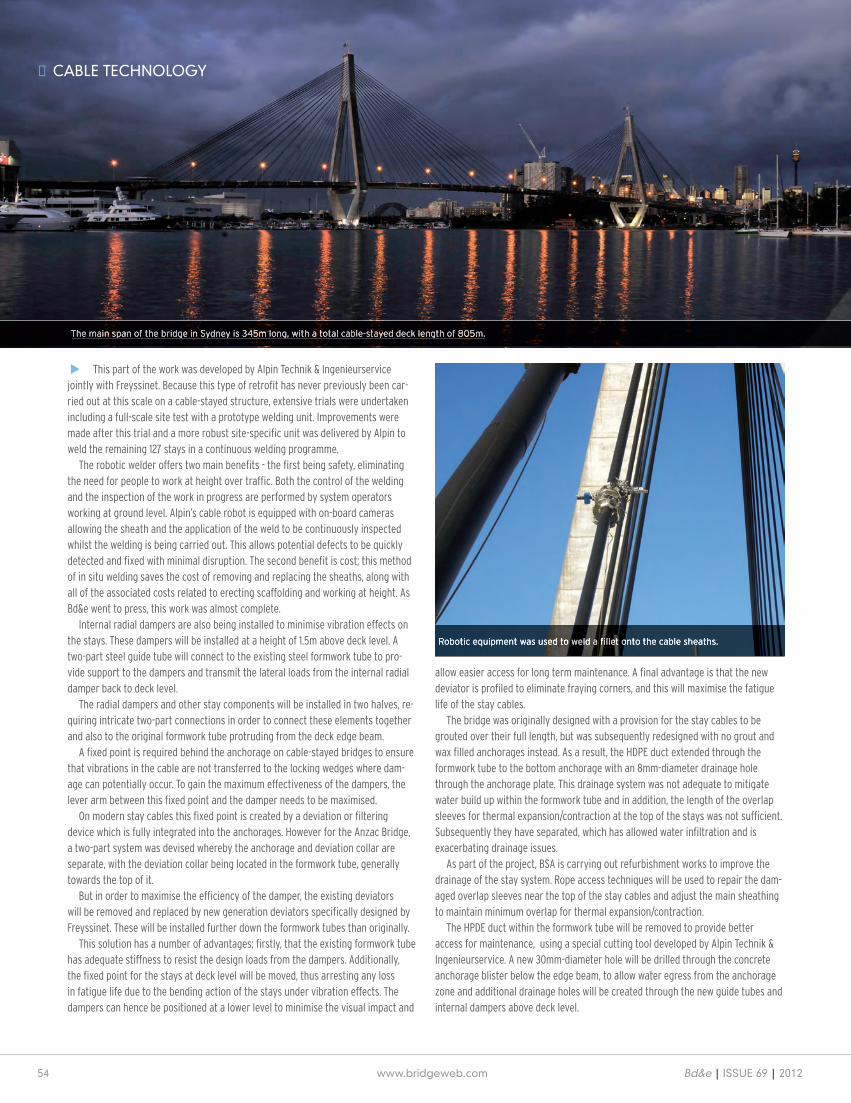
The main span of the bridge in Sydney is 345m long, with a total cable-stayed deck length of 805m.
Robotic equipment was used to weld a fi llet onto the cable sheaths.

Bd&e | ISSUE 69 | 2012 www.bridgeweb.com 55
CABLE TECHNOLOGY n
When the bridge was built the strands were protected along their length with an HDPE coating extruded over the galvanised strand with a petroleum wax fi lling for durability. At the anchorage ends the HDPE coating was removed to allow the steel wedges to grip the strand at the anchorage. The region in front of the anchor was covered with an anchor cap and the region behind it was separated from the rest of the stay with a stuffi ng box. These two regions were then injected with wax to prevent corrosion of the strand.
Inspections of the bottom anchorages showed that the quality of the wax had de-teriorated over time and in some locations it was leaking. BSA carried out extensive on-site trials to develop a method which would allow the wax to be removed without damaging the stay cables. The solution involves inserting heating rods through the anchorage bearing plate at specifi c locations in the anchorage zone and heating the wax in a controlled way to enable it to be drained. Once this has been removed, each anchorage will be refi lled by injecting it with Cirinject wax.
The number of new components being added to the stay cables at deck level will demand an increase in maintenance, and this in turn requires the existing access system to be upgraded. Previous access arrangements involved a temporary static line to access each stay cable at deck level. For the rehabilitation works, a tempo-rary access walkway was required along the full length of the bridge.
Through a value-for-money workshop, it was determined that upgrading the temporary access walkway to a permanent walkway would provide a safer access system across the bridge for long term maintenance.
New deck level maintenance walkways have been installed along the outside of the edge beams over the entire 650m bridge length. They are 700mm wide and
were built using four custom launching gantries designed by BSA.The walkways are made of aluminium structural elements with FRP grating,
chosen for their low whole-life cost and the fact that they are light enough to assemble in situ by hand. During the construction phase a BSA-designed transport system running on temporary rails is being used on the walkway to allow transport of materials and provision of crane assistance to each stay location.
Meanwhile new industrial lifts are being installed inside the northern leg of each tower to improve access from the deck level to the bottom of the tower head, which is currently accessed via an internal ladder system. The new lifts will have a 500kg safe working load.
The bridge was built in the early 1990s and carries 125,000 vehicles per day.
T E N S O S T R U C T U R E S
SUSPENSION STRUCTURES
CABLE STAYED STRUCTURES
E N G I N E E R I N G
Design support
Standard and dedicated tensionsystems production
Installation and tensioning proceduredefinition
Site assistance and installation
Maintenance and inspection services
Stahlbau Pichler
Redaelli Tecna S.p.A.Engineering Division
Via A. Volta, 1620093 Cologno Monzese
Milano, ItalyTel. +39 02 25307291Fax +39 02 25307292
Design support
Standard and dedicated tensionsystems production
Installation and tensioning proceduredefinition
Site assistance and installation
Maintenance and inspection services
T E N S O S T R U C T U R E S
SUSPENSION STRUCTURES
CABLE STAYED STRUCTURES
E N G I N E E R I N G
BRIDGE MEZZA PAGINA 16-10-2012 15:46 Pagina 1

56 www.bridgeweb.com Bd&e | Issue 69 | 2012
n CABLe TeCHNOLOGY
Access within the actual tower head is cramped due to the presence of the stay cables and anchorage caps. To improve the safety of movement of maintenance materials, new hoists will be installed in extremely tight constraints to provide a 300kg safe working load. The hoists will operate a custom-designed tray system which is guided on tracks inside the tower. One of the key criteria for the hoists was also that it could act as an emergency egress system in the event of a person being injured in the tower.
New under-deck maintenance catwalks are being installed to provide access to the eight stay cable anchorages at each end of the bridge, which can only cur-rently be accessed by the use of work platforms from ground level.
The bridge geometry makes it impossible for the under-deck gantry to reach all the stay anchorages and future plans to develop the land under the back-spans of the bridge mean that access for elevated work platforms cannot be relied upon.
These catwalks will be made of fabricated aluminium Warren trusses spanning approximately 10.3m between supports, clad with a perforated aluminium sheet to produce a plain surface mirroring the edge beam above. Aluminium was chosen as the preferred material due to its low long-term maintenance requirements.
The trusses will be supported by L-shaped fabricated steel beams connected to the inside face of the deck edge beam to create the effect of a floating catwalk. Access will be provided via the underdeck gantry which will dock into purpose-designed bays on the ends of the catwalks.
Some minor modifications to the existing underdeck gantry will also be under-taken as part of the works. The main change involves improving the emergency
egress system and maximising the space around the stay anchorages by install-ing extendable sliding aluminium platforms.
As part of the works, BSA investigated the adequacy of the safety fence on the northern edge of the bridge, next to the pedestrian walkway. The existing fence did not meet the strength or security requirements of the project brief and the team decided that a safety fence should also be installed on the southern edge.
The new fences will be constructed of a 3m-high aluminium post and rail type system with security weldmesh panels. The fence frames are formed of two primary load carrying posts at a 4.5m nominal spacing, with secondary smaller posts located centrally between the primary posts. A 170mm-diameter top rail will be bolted to the primary posts, forming a portal frame for longitudinal stability. Expansion joints will be located in the top rail and will include a spigot that will allow temperature movements and make future replacement possible.
The fence posts will be fabricated, tapered aluminium I-sections, with a slight curvature to provide an out of plane stiffness to the mesh panels to minimise warping or ‘pillowing’. The taper of the I-section is intended to maximise the ef-ficiency of the posts whilst minimising the visual impact.
The mesh panels will be built using powder-coated steel with an aperture size that provides good transparency, even when viewing from oblique angles n
Rod Oates is technical interface manager for RMS; Eric Kuhn is general manager of Alpin Technik; Andrew Thompson is alliance manager for Baulderstone; Xavier Koscher is project delivery manager for Freyssinet; Robert Craig is project deliv-ery manager for Sage Automation.
THE PROVENSTEEL BRIDGE DESIGN SOLUTION
The leading software package for designing and rating curved and straight steel girder bridges for compliance with AASHTO
ASD, LFD, & LRFD specifications.
Tel: (573) 446-3221 [email protected]
leading software package