p517/617 lec3, p1 r-l-c ac circuits - department of …gan/teaching/summer...p517/617 lec3, p1 r-l-c...
TRANSCRIPT
P517/617 Lec3, P1R-L-C AC Circuits
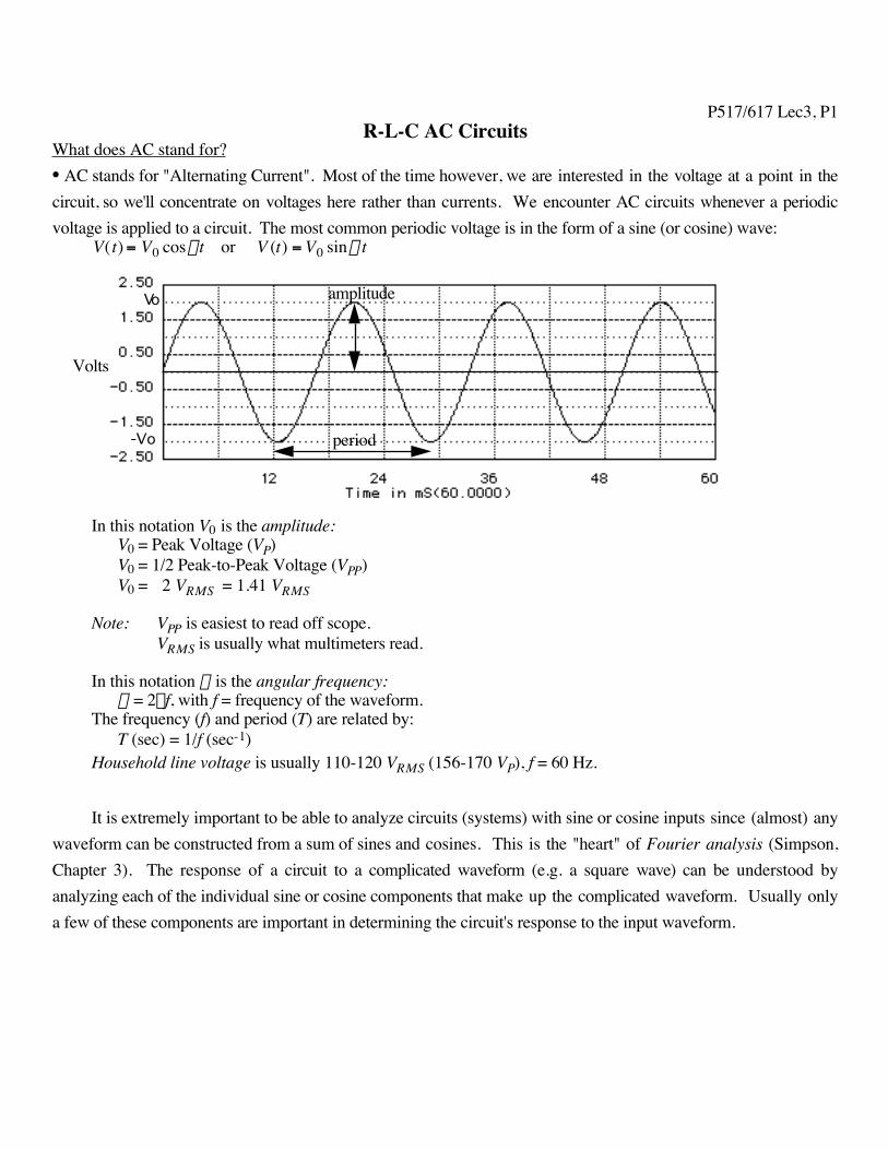
What does AC stand for?• AC stands for "Alternating Current". Most of the time however, we are interested in the voltage at a point in thecircuit, so we'll concentrate on voltages here rather than currents. We encounter AC circuits whenever a periodicvoltage is applied to a circuit. The most common periodic voltage is in the form of a sine (or cosine) wave:
V(t) = V0 coswt or V (t) = V0 sinwt
Volts
period
amplitudeVo
-Vo
In this notation V0 is the amplitude:V0 = Peak Voltage (VP)V0 = 1/2 Peak-to-Peak Voltage (VPP)V0 = ÷2 VRMS = 1.41 VRMS
Note: VPP is easiest to read off scope.VRMS is usually what multimeters read.
In this notation w is the angular frequency:w = 2pf, with f = frequency of the waveform.
The frequency (f) and period (T) are related by:T (sec) = 1/f (sec-1)
Household line voltage is usually 110-120 VRMS (156-170 VP), f = 60 Hz.
It is extremely important to be able to analyze circuits (systems) with sine or cosine inputs since (almost) anywaveform can be constructed from a sum of sines and cosines. This is the "heart" of Fourier analysis (Simpson,Chapter 3). The response of a circuit to a complicated waveform (e.g. a square wave) can be understood byanalyzing each of the individual sine or cosine components that make up the complicated waveform. Usually onlya few of these components are important in determining the circuit's response to the input waveform.
P517/617 Lec3, P2R-C Circuits and AC waveforms• There are many different techniques for solving AC circuits, all of them are based on Kirchhoff's laws. When wesolve for the voltage and/or current in an AC circuit we are really solving a differential equation. The differentcircuit techniques are really just different ways of solving the same differential equation.
• brute force solution to differential equation • complex numbers (algebra) • Laplace transforms (integrals)
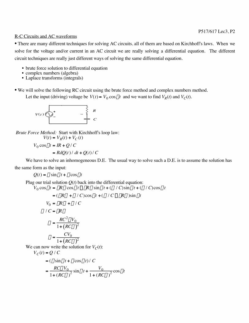
• We will solve the following RC circuit using the brute force method and complex numbers method.Let the input (driving) voltage be V(t) = V0 coswt and we want to find VR(t) and VC(t).
R
CV t( )
Brute Force Method: Start with Kirchhoff's loop law:V(t) = VR(t) + VC (t)
V0 coswt = IR + Q / C= RdQ(t ) / dt + Q(t) / C
We have to solve an inhomogeneous D.E. The usual way to solve such a D.E. is to assume the solution hasthe same form as the input:
Q(t) = a sinwt + b coswtPlug our trial solution Q(t) back into the differential equation:
V0 coswt = aRw coswt - bRw sinwt + (a / C)sinwt + (b / C)coswt= (aRw +b / C)coswt + (a / C - bRw )sin wt
V0 = aRw +b / Ca / C = bRw
a =RC2wV0
1+ RCw( )2
b =CV0
1+ RCw( )2
We can now write the solution for VC(t):VC(t) = Q / C
= (a sinwt + b coswt) / C
=RCwV0
1+ (RCw )2 sinwt +V0
1 + (RCw )2 coswt
P517/617 Lec3, P3
We would like to rewrite the above solution in such a way that only a cosine term appears. In this form wecan compare it to the input voltage. From the previous page we have:
VC(t) =RCwV0
1+ (RCw )2 sinwt +V0
1 + (RCw )2 coswt
=V0
1+ (RCw)2RCw
1+ (RCw )2sinwt +
11 + (RCw )2
coswtÈ
Î Í
˘
˚ ˙
We get the above equation in terms of cosine only using the following dirty trick from basic trig:cos(q1 - q2 ) = sin q1 sinq2 + cosq1 cosq2
We can now define an angle such that:cosf =
11 + (RCw )2 , sinf =
RCw
1 + (RCw)2 , tan f = RCw
Finally (!) we can write the desired expression for VC(t):
VC(t) =V0
1+ (RCw)2 cos(wt - f )
From the above expression we see that VC(t) and V0(t) are out of phase.
Using the above expression for VC(t), we obtain:VR (t) = IR
= R dQdt
= RC dVCdt
=-RCwVo
1+ (RCw )2sin(wt - f )
Again, we would like to have cosines instead of sines. We do this using:- sin q = cos(q + p / 2)
Finally (!!) we have:VR (t) =
RCwVo
1+ (RCw )2 cos(wt - f + p2 )
• Some things to note:VC(t), VR(t), and I(t) are all out of phase with the applied voltage.I(t) and VR(t) are in phase with each other.VC(t) and VR(t) are out of phase by 900.The amplitude of VC(t) and VR(t) depend on w.
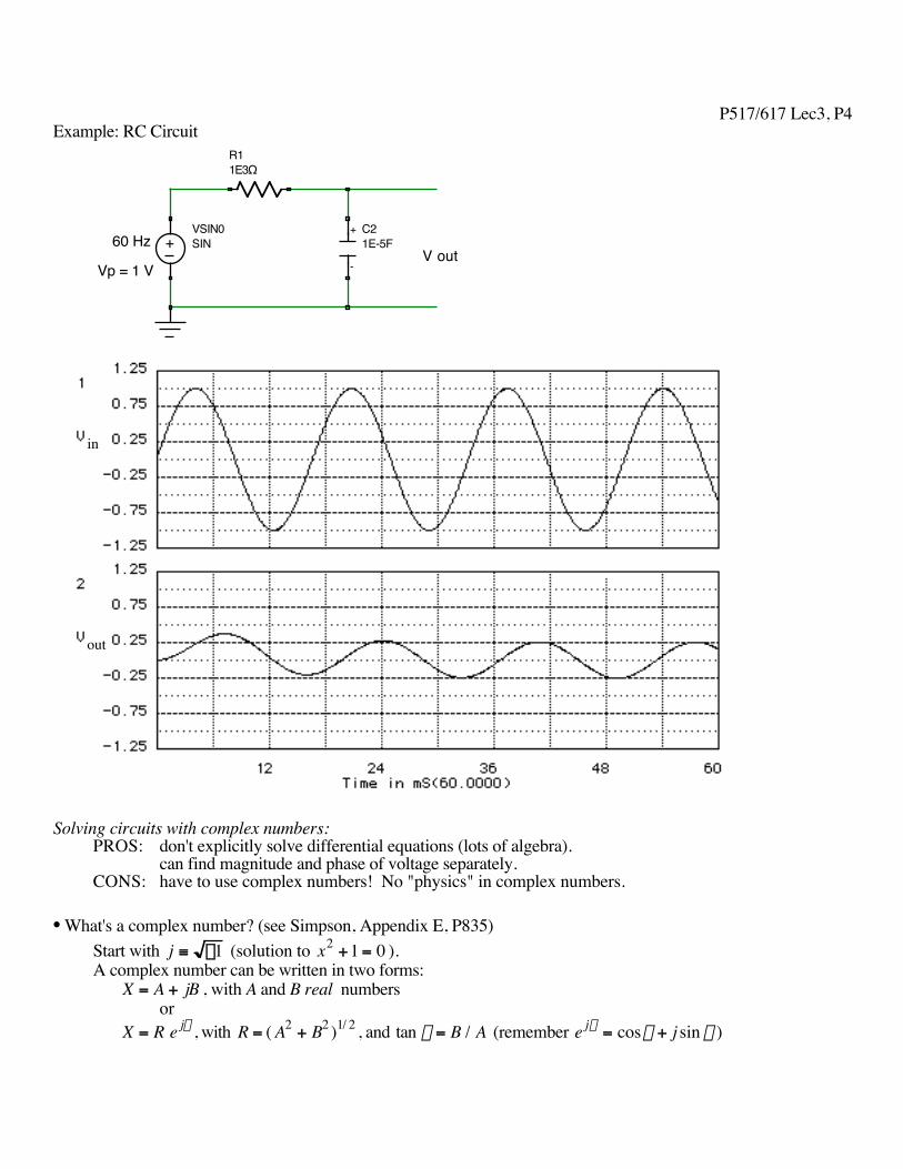
P517/617 Lec3, P4Example: RC Circuit
+ SINVSIN0
R11E3Ω
C21E-5F
+
-V out
60 Hz
Vp = 1 V
in
out
Solving circuits with complex numbers:PROS: don't explicitly solve differential equations (lots of algebra).
can find magnitude and phase of voltage separately.CONS: have to use complex numbers! No "physics" in complex numbers.
• What's a complex number? (see Simpson, Appendix E, P835)Start with j ≡ -1 (solution to x2 +1 = 0 ).A complex number can be written in two forms:
X = A + jB , with A and B real numbersor
X = R e jf , with R = ( A2 + B2 )1/ 2 , and tan f = B / A (remember e jf = cosf + j sin f )
P517/617 Lec3, P5Define the complex conjugate of X as:
X* = A - jB or X* = R e- jf
The magnitude of X can be found from:| X|= ( XX*)1/2 = (X * X)1/ 2 = (A2 + B2 )1/2
Suppose we have 2 complex numbers, X and Y with phases a and b respectively,
Z =XY
=X e ja
Y e jb =XY
e j(a -b )
The magnitude of Z is just |X|/|Y|, while the phase of Z is a - b.• So why is this useful?
Consider the case of the capacitor and AC voltage:V(t) = V0 coswt
= Re al V0e jwt( )I(t) = C dV
dt= -CwV0 sin wt
= Re al jwCV0e jw t( )
= Re al V0e jw t
1 jwCÊ
Ë Á ˆ
¯ ˜
= Re al VXC
Ê
Ë Á ˆ
¯ ˜ with V and XC complex
We now have Ohm's law for capacitors using the capacitive reactance XC.
XC =1
jwCWe can make a similar case for the inductor (V = LdI / dt ):
I(t) =1L
V0Ú coswt dt
=V0 sin wt
Lw
= Re al V0e jwt
jwLÊ
Ë Á ˆ
¯ ˜
= Re al VXL
Ê
Ë Á ˆ
¯ ˜ with V and XL complex
We now have Ohm’s law for inductors using the inductive reactance XL:XL = jwL

P517/617 Lec3, P6• XC and XL act like frequency dependent resistors. However they also have a phase associated with them due totheir complex nature.
XL fi 0 as w fi 0 (short circuit, DC)XL fi • as w fi • (open circuit)XC fi 0 as w fi • (short circuit)XC fi • as w fi 0 (open circuit, DC)
• Back to the RC circuit. Allow voltages, currents, and charge to be complexVin = V0 coswt
= Re al V0ejwt( )
= Re al VR + VC( )We can write an expression for the charge (Q) taking into account the phase difference (f) between applied
voltage and the voltage across the capacitor (VC).Q(t) = CVC(t)
= Ae j (wt-f )
where Q and VC are complex, A and C real.
We can find the complex current by differentiating the above:I(t) = dQ(t) / dt
= jwAe j(w t- f )
= jwQ(t )= jwCVC (t)
Vin = VC + VR
= VC + IR= VC + jwCVCR
VC =Vin
1 + jwRC
= Vin
1jwC
R +1
jwC
= VinXC
R + XC
The above looks like a voltage divider equation!!!!!
P517/617 Lec3, P7We can easily find the magnitude of VC
VC =Vin XCR + XC
=V0
1wC
R2 + (1 wC)2
=V0
1+ RCw( )2
which is the same as the result on page 3.
Is this solution the same as what we had when we solved by brute force?
VC = Real Vin1 + jwRC
Ê
Ë Á ˆ
¯
= Real V0e jw t
1 + jwRCÊ
Ë Á ˆ
¯ ˜
= Real V0e jwt
1 + (wRC)2 e jf
Ê
Ë Á
ˆ
¯ ˜
where f is given by tan f = wRC .
VC = Real V0e j( wt-f )
1 + (wRC)2
Ê
Ë Á
ˆ
¯ ˜
=V0 cos(wt - f )
1 + (wRC)2
YES the solutions are identical.
• We can now solve for the voltage across the resistor.Start with the voltage divider equation in complex form:
VR =VinR
R + XC
VR =Vin R
R + XC
=V0R
R2 + (1 wC)2
=V0wRC
1 + (wRC)2
This amplitude is the same as the brute force differential equation case!
P517/617 Lec3, P8• Important note:
When we add complex voltages together we must take into account the phase difference between them. Thus,the sum of the voltages at a given time satisfy:
V02 =|VR|2 +|VC |2 and not V0 =|VR| +|VC |
R-C Filters• Filters:
Allow us to select (reject) wanted (unwanted) signals on the basis of their frequency structure.Allow us to change the phase of the voltage or current in a circuit.
Define the gain (G) or transfer (H) function of a circuit:G( jw ) = H( jw ) = Vout / Vin (jw is often denoted by s).
G is independent of time, but can depend on w, R, L, C.
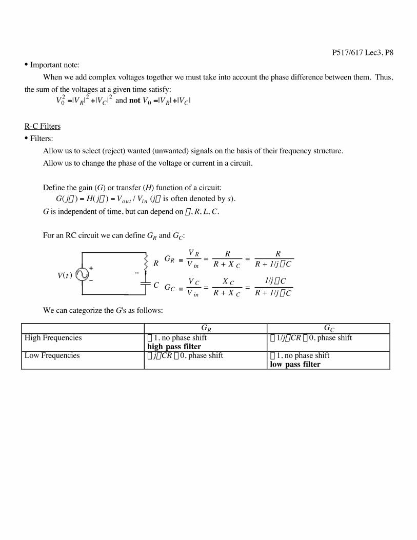
For an RC circuit we can define GR and GC:
R
C
GR ≡ V RV in
= RR + X C
= RR + 1/j wC
GC ≡V CV in
= X C
R + X C =
1/j wCR + 1/j wC
V t( )
We can categorize the G's as follows:
GR GCHigh Frequencies ª 1, no phase shift
high pass filterª 1/jwCR ª 0, phase shift
Low Frequencies ª jwCR ª 0, phase shift ª 1, no phase shiftlow pass filter
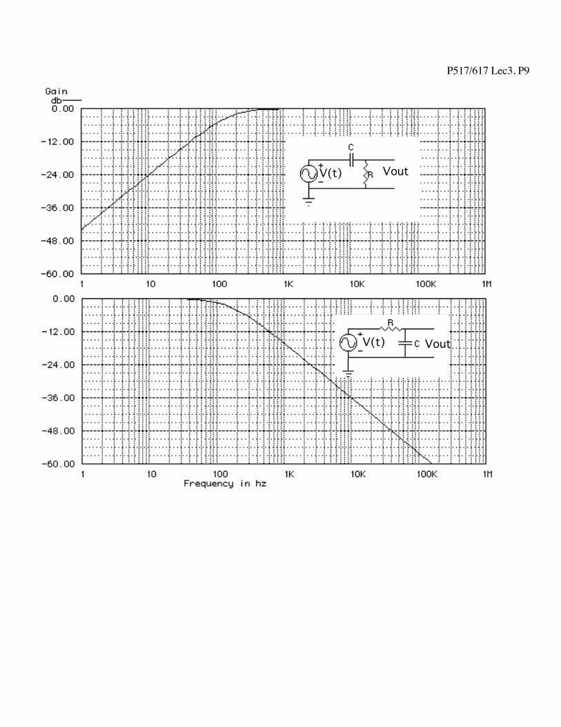
P517/617 Lec3, P9
R
CV(t)
GR ≡ VRVin
= RR + XC
= RR + 1/j wC
GC ≡ VCVin
= XCR + XC
= 1/j wCR + 1/j wC
V(t) Vout
VoutV(t)
P517/617 Lec3, P10
V(t)
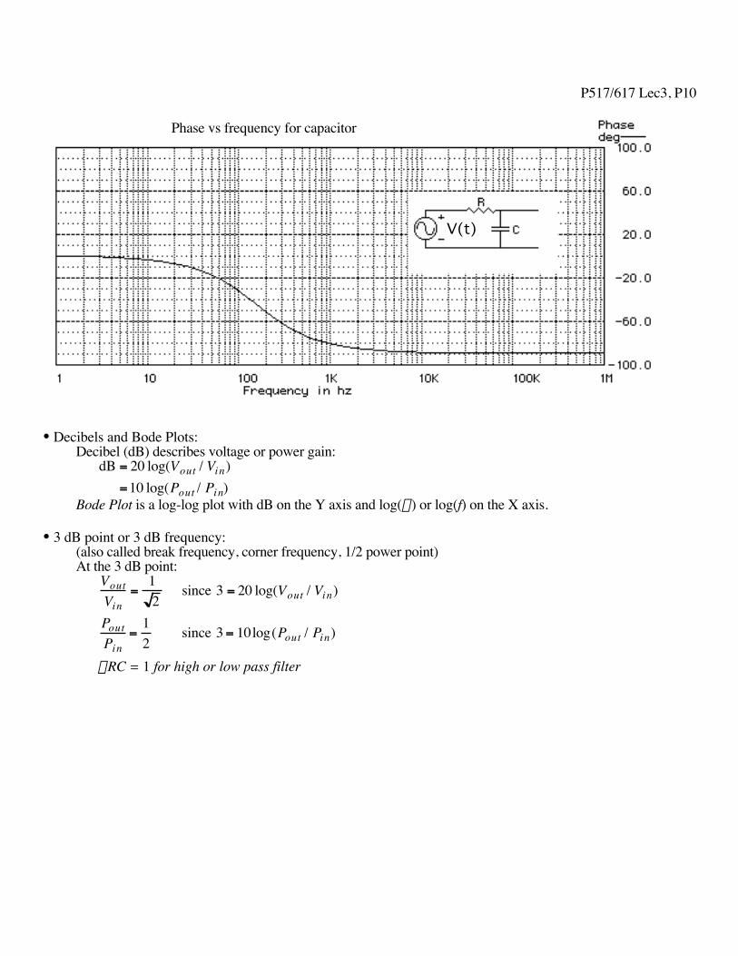
Phase vs frequency for capacitor
• Decibels and Bode Plots:Decibel (dB) describes voltage or power gain:
dB = 20 log(Vout / Vin)=10 log(Pout / Pin)
Bode Plot is a log-log plot with dB on the Y axis and log(w) or log(f) on the X axis.
• 3 dB point or 3 dB frequency:(also called break frequency, corner frequency, 1/2 power point)At the 3 dB point:
VoutVin
=12
since 3 = 20 log(Vout / Vin)
PoutPin
=12
since 3 = 10log(Pout / Pin)
wRC = 1 for high or low pass filter