p y,f' - nasa · ... (ignition energy for a sugar dust explosion in a sugar refinery) ... are...
TRANSCRIPT

NASA Technical Paper 3553
/',,¢" - _2 ©
p_ y,f'Developmental Problems and Their Solution for the SpaceShuttle Main Engine Alternate Liquid Oxygen High-PressureTurbopump: Anomaly or Failure Investigation the KeyR.S. Ryan and L.A. Gross
(NASA-TP-3553) DEVELOPMENTALPROnLEMS AND THEIR SOLUTION FOR THE
SPACE SHUTTLE MAIN ENGINE ALTERNATE
LIQUID OXYGEN HIGH-PRESSURE
TUR_OPUMP: ANOMALY OR FAILURE
INV_STIGATION THE KEY (NASA.
I Marshall Space Flight Center} 79 p H1/20
N95-28263
Unclas
0050110
May 1995
https://ntrs.nasa.gov/search.jsp?R=19950021842 2018-08-26T03:14:32+00:00Z


TABLE OF CONTENTS
I. INTRODUCTION .............................................................................................................
II. GENERAL .........................................................................................................................
III. FAULT TREE/LOGIC DIAGRAM/ACTIONS/GENERAL VIBRATION
AND BEARING TEAMING .............................................................................................
IV. HIGH-SYNCHRONOUS VIBRATION ...........................................................................
A. Dynamic Characteristics of Turbomachinery .............................................................
B. Rotordynamic Characteristics of ATD Lox Pump .....................................................
V. BEARING WEAR .............................................................................................................
VI. OVERALL CONCLUSION/SUMMARY ........................................................................
REFERENCES ...............................................................................................................................
BIBLIOGRAPHY ..........................................................................................................................
Page
1
3
5
13
13
16
4O
67
69
7O
PRECEDING I gC/K.NOTiii

LIST OF ILLUSTRATIONS
Figure
1.
2.
3.
4.
5.
.
7.
8.
9.
10.
11.
12.
13.
14.
15.
16.
17.
18.
19.
20.
21.
22.
Title
ATD high-pressure oxidizer turbopump (HPOTP) .......................................................
Turbomachinery rotordynamics .....................................................................................
Rotordynamic correlation ..............................................................................................
FTA symbols .................................................................................................................
Typical fault tree (ignition energy for a sugar dust explosion in a sugar
refinery) .........................................................................................................................
Cause and effect fishbone diagram ................................................................................
HPOTP synchronous vibration fault tree .......................................................................
Bearing distress investigation fault tree .........................................................................
HPOTP synchronous vibration fault tree team ..............................................................
HPOTP sample fault tree ...............................................................................................
Linear resonance response .............................................................................................
Nonlinear resonance response .......................................................................................
Bearing force versus deflection .....................................................................................
System response .............................................................................................................
PEBB/damper seal .........................................................................................................
Vibration response scenarios .........................................................................................
Typical vibration response .............................................................................................
HPOTP synchronous vibration resolution process ........................................................
MSFC/Pratt & Whitney vibration team .........................................................................
ATD rotordynamic interactions .....................................................................................
HPOTP synchronous vibration problem characteristics ................................................
Reduced critical team synergistic effects ......................................................................
Page
3
4
5
6
7
8
9
10
12
12
14
15
15
17
18
19
20
21
22
22
23
23
iv

LIST OF ILLUSTRATIONS (Continued)
Figure
23.
24.
25.
26.
27.
28.
29.
30.
31.
32.
33.
34.
35.
36.
37.
38.
39.
40.
41.
42.
43.
44.
Title
Critical tracks near the pump rotating speed (pump configuration 3-1A) .....................
Critical tracks near the pump rotating speed (pump configuration 4-1D) .....................
Hot-fire data of radial synchronous acceleration versus pump speed ...........................
ATD HPOTP deadband interaction ...............................................................................
Analytical sideband simulation ......................................................................................
Damper seal stiffness versus convergence ratio ............................................................
Pump end ball bearing stiffness as a function of bearing tilt .........................................
Increased inducer tip clearance reduced synchronous forcing function with
no loss in suction performance margin ..........................................................................
ATD HPOTP synchronous flow dynamics ....................................................................
ATD synchronous vibration fix summary .....................................................................
HPOTP vibration configuration study plan ...................................................................
SSME/ATD HPOTP unit 06-2 vibration .......................................................................
Unit 03-1A vibration envelope for turbopump without corrective fixes (03-1)and intermediate corrective fix (03-1A) ........................................................................
Synchronous vibration onset eliminated from operating range .....................................
1X synchronous trackings versus time ..........................................................................
1X synchronous trackings versus time--unit 7-2A .......................................................
End-to-end runs of two of the development pumps .......................................................
Bearing coolant flow temperature .................................................................................
Bearing coolant temperature rise ...................................................................................
SSME/ATD HPOTP pump end ball bearing experience before corrective solution .....
Bearing life ....................................................................................................................
Bearing wear parameters ...............................................................................................
Page
25
25
26
26
27
28
29
30
31
32
34
35
36
37
38
39
41
51
51
52
53
53
V

LIST OF ILLUSTRATIONS (Continued)
Figure
45.
46.
47.
48.
49.
50.
51.
52.
Title
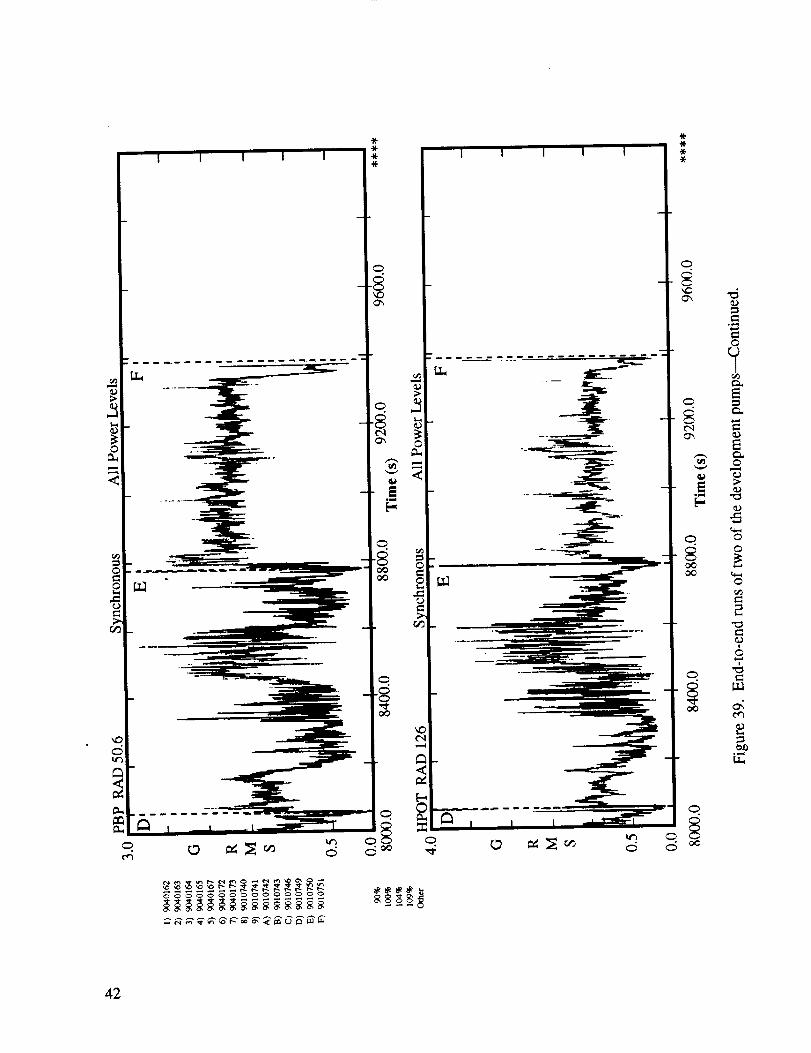
Operation of misaligned bearing ...................................................................................
Cage thermal model of bearing distress scenario ..........................................................
Loss of lubrication bearing failure simulation ...............................................................
CFD analysis of ATD bearing coolant flows ................................................................
Stribeck curve (coefficient of friction versus viscosity by velocity/pressure) ...............
Lox EHD film thickness analysis ..................................................................................
PEBB outer race piloted cage ........................................................................................
SSME/ATD HPOTP bearing configuration ..................................................................
Page
56
57
58
61
62
62
64
65
vi

TECHNICAL PAPER
DEVELOPMENTAL PROBLEMS AND THEIR SOLUTION FOR THE
SPACE SHUTTLE MAIN ENGINE ALTERNATE LIQUID OXYGENHIGH-PRESSURE TURBOPUMP: ANOMALY OR FAILURE
INVESTIGATION THE KEY
I. INTRODUCTION
The space shuttle main engine (SSME) alternate turbopump developmental (ATD) program,
particularly the high-pressure oxidizer pump, has experienced problems that were program threaten-ing. The problem solutions, in a timely manner, were key to program continuation and success. This
was accomplished using a concurrent engineering-multidiscipline team with members from
NASA/MSFC, Pratt & Whitney, Rocketdyne, and special consultants as needed. This paper serves
two purposes: (1) to demonstrate the formal failure investigation and solution approach and (2) to
provide documentation of the basic problems and their solutions.
The key to correcting deficiencies is having a sound supporting technology program and the
use of a concurrent Government-contractor engineering team coupled with the formal fault tree
approach. It is the nature of engineers to want to make intuitive jumps and to check out a proposed
solution without using a formal guided approach. As powerful as intuition is, this approach generally
results in additional problems, costly additional changes, and operational constraints. This isbecause high-performance systems, such as the oxidizer turbopump, are finely tuned systems
balanced between conflicting or competing parameters such as cost, weight, performance, and relia-
bility. The authors' experience is replete with examples of synergistic effects resulting from small
changes which lead to other problems or performance loss. In order to deal with this synergism,
sensitivity analysis has to be accomplished in order to first understand the cause and second to
arrive at a problem fix. This task becomes a part of the formal failure investigation.
A fault tree analysis method is a good choice to establish the problem cause or causes and to
define a properly balanced solution. This formalized approach consists of a set of basic steps that
have known characteristics, t The steps are:
(1) Define the basic characteristics of the system
(2) Derive a cause and effect by failure modes and effects analysis (FMEA) or fault tree(can use the fishbone)
(3) Develop a logic diagram to resolve the fault tree (rule in or out potential causes)
(4) Conduct analyses and tests to resolve the fault tree (formalized actions)
(5) Determine the cause or causes
(6) Recommend potential fixes.

The characteristicsof this processare:
(1) Formal fault treeclosurematrix
(2) Develop supportingdatafiles
(3) Date all papers(evolutionarychangehistory)
(4) No "eureka's"
(5) Formal, dated,personalizedactionitems
(6) Lessonslearnedconclusions.
Two problemsexperiencedby theATD liquid oxygen(lox) pump arediscussedin this paper:(1) high-synchronousvibration and (2) bearingdegradationand short bearinglife. Theseproblemsareof special interest becausethey illustrate the fundamentalaspectsof balancingcomplex, inter-active, nonlinearperformanceparameters(technicalissues)during designand development,requir-ing a concurrentengineeringteamusingtheformalizedfault treeapproach.
The technical aspectsof theseinteractingperformanceparameters,as well as the fault treeapproach,arevery instructive as lessonslearnedfor futureprojects.Someof the interestingparame-ters are: rotordynamics (responseand stability), flow efficiency, induced environments (thermal,vibration, flow), bearing characteristics(cooling, lubrication, materials,etc.), and geometriccharac-teristics.Thesecanbe summarizedunder five major headings:
( 1) Hydrodynamics:performanceandinducedenvironments
(2) Rotordynamics:balance,vibration, stability
(3) Bearings:characteristicsandlife
(4) Housing and supportstructure(stiffnessand flow geometrics)
(5) Damping seals:characteristicsandperformance.
This paperwill discussthe two developmentproblems,(1) vibration and (2) bearing life--how they were approached, the technical issues,and the solutions implemented. Both of theproblems are closely related and are nonlinear in nature, with many strong interactions.Understanding the associatedsensitivities and the resulting trades was essential to solving theproblemswithout introducing other problems.Taguchi designof experimentswasusedto augmentand guide diagnostic testing. The underlying principle is: high-performance machines are acompromise,a balancingact; hence,solving one problem,as a minimum, reducesthe margins inanotherarea--many times at the expenseof performance,cost,and reliability.
2

II. GENERAL
Turbopumps (oxidizer and fuel) are used to increase pressures to the levels required in the
combustion chambers of high specific impulse (ISP) liquid rocket engines. The SSME uses a two-stagepump system and a dual combustion cycle to achieve very higu ISP (453 s). The high-pressure lox
pump, the subject of this paper, has a three-stage turbine driven by hydrogen/oxygen combustion
products that powers two liquid oxygen pumps on a common shaft. The larger of the two pumps, adouble-suction pump with integral inducers, supplies oxygen at 4,000 lb/in 2 to the main combustion
chamber. The smaller pump supplies lox at 8,000 lb/in 2 for combustors driving the engine turbines. Across-section of the turbopump is shown in figure 1.
PEBB DeadbandMain Pump
Turbine End Rollerand Ball Bearing
PEBB Preload
PreprimerPump
InducerIntepropellantSeal Package
3 Stage Turbine
Figure 1. ATD high-pressure oxidizer turbopump (HPOTP).
The rotor is supported by a roller bearing on the turbine end, and a ball bearing and damping seal
on the pump end. Axial thrust is controlled during operation by a double-acting balance piston on the
shrouds of the main pump impeller. Transient axial thrust is controlled by the two ball bearings. The ball
bearings are preloaded with a spring axially to ensure proper ball race contact. In order to guaranteeaxial movement capability, the ball bearings are built with a clearance between the outer race and
bearing support structure. The purpose of the damping seal is to provide damping for rotordynamicmodes, ensuring low vibration and stability. Designing the damping seal to provide fluid stiffness results
in creating a parallel support system on the pump end. This parallel load path produces interactions andsystem trades that must be tuned and balanced.
The pump operates over a speed range of 0 to 24,500 r/min. Temperatures in the turbine are
approximately 1,500 °R with an inlet pressure of 4,800 lb/in 2. A purge seal system is located between
the pumps and turbine to prevent hydrogen from mixing with oxygen during operation.

The above characteristics are obtained in a system of minimum size and weight. The pump
has high-energy density and operates at a high speed. The conflicting requirements between the
performance requirements and minimum weight lead to a finely tuned system. The result is a fine
balance between performance (ISP, flow, pressure), stability, weight, and lifetime, as well as theunwanted rogue forces that affect its own system and the rest of the engine system.
This brings into play several specialized disciplines such as structural analysis, structural
dynamics, rotordynamics, thermal, fluid flow, bearings, seals, materials, and performance in a highly
interactive and sensitive manner. Generally, design analysis cannot fully replicate this phenomenonbecause analysis is just models built around approximate assumptions and incomplete data. An
example is shown in figure 2. The output of the models is the turbomachinery characteristics that can
be understood by varying the various design parameters. In the final analysis, the only completecharacterization is the hot firing of the turbomachinery system. This means that specialized tests
(structure, flow, etc.), using special instrumentation, are run to quantify parameters for the models
and to certify the system. The results of the analysis are then correlated with the hot-fire data
(obtained using special instrumented development hardware) to baseline the models for design use.In addition, hardware tear down and inspection provide further correlation and insight (fig. 3).
Through this process of dispersed parameter analysis supported by specialized tests to define the
parameters correlated to development hot-fire data (dispersed to understand margins) and hot-fire
hardware inspections, a balanced design is accomplished. Similar design, analysis, and correlation
cycles are followed for all of the key aspects of the turbomachine. The important fact to remember is
that the pump operates as a system, not a set of independent disciplines, in a highly interactivemanner.
Damping Seal [* Damping Seal I• Stiffness [ _ ]
• Damping ] * Density |• temperature j
_._ _l Bearing _ __.-,,.,_ i
[ I I_ • Vibration _ _ I
_ _ Speed __ Pressure _ ]
_ • Temperature _ I
_ •Deflect,on "_'
Bearing Deadband] *"..._-7777""- 1 * Nonlinear interaction between deadband I
• 5tmness ] and damping seal performance, also other ]
/ factors such as 3P
Side Forces
• Deflecting
Other Forces
• Pump Impeller• Pump Inducer
Seal Forces
• Damping• Stiffness
Alford Forces
Balance Piston
• Stiffness
• Damping• Axial Position
Figure 2. Turbomachinery rotordynamics.
4

Rotordynamic Model
• Sensitivity• Pre and Post Test
Correlation
Hot-Fire Data
• Diagnostic• Statistical
Correlation
Post Hardware Characteristic
• Build Condition
• Wear Patterns• Thermal Discoloration
• Dimensional Changes
Structural Analysisand Verification
• Pressure
• Thermal
• Dynamic- 2-D
-3-D
- Test
Environments
• Pressure
• Flow
• Vibration
Correlation Cause v Fix
Figure 3. Rotordynamic correlation.
During development, when problems occur due to this fine tuning of design parameters, a
formal procedure must be followed to ensure proper understanding of the system and the correct
solutions. This approach is the fault tree with supporting logic diagrams, analyses, and tests. The
next section discusses this approach.
III. FAULT TREE/LOGIC DIAGRAM/ACTIONS/GENERAL
VIBRATION AND BEARING TEAMING
Determining the cause and the solution to developmental problems experienced in space
programs is most efficiently accomplished using a concurrent engineering-multidiscipline team
employing fault trees with support logic diagrams and formal action items. The concurrent
engineering-multidiscipline team is necessary to ensure communications and understanding.
The fault tree approach focuses the activity by requiring the use of supporting data to formally
close all branches not contributing to the problem. These data are acquired by analyses, special
tests, and system tests. The point to remember is that all analyses and special tests are merely
models of the real thing and are based on many assumptions. The only true data are obtained from
instrumented system tests and inspection and evaluation of the hardware after these tests. In the
final analysis, the hardware has the answer. The problem is our ability to read it. One usually reads
5

it basedon the theoriesone understands,which emphasizesthe needto have all plausible theoriesinvestigatedand understood.Consultantscanhelpgreatly in this area.
The fault tree approach(fishbonediagramscan beusedin placeof the fault tree) requiresathorough understandingof the system.Basedon this understanding,all the potential causesandcontributing parametersare identified. Using thesecauses,a fault tree is laid out that identifies thepathof the potential causes.Figure 4 showstheelementsof a fault tree.Figure 5 is anexampleof afault tree developed for a dust explosion in a sugar mill. Figure 6 is an example of a fishbone diagram
for cause and effect for categorizing mistakes. How and which of these to use depends on the prob-
lem and the team. Many times the symbols described can be eliminated resulting in a straight-line
cause tree, simplifying the layout of work.
LOGIC GATES
IllAND gate: failure will occur if all inputs fail
(parallel reliability)OR gate: failure will occur if any input fails
(series reliability)
EVENT GATES
A failure which results from A basic failure which is
combined effects of other statistically dependentfailures on other events, but not
developed downward
A failure which is
statistically dependent onother events, but is not
developed downward
A failure which isstatistically dependenton other events and is
important enough tojustify separate FTA
Figure 4. Fault tree analysis (FTA) symbols.
This straight-line approach, in conjunction with logic flow diagrams, was used by both the
vibration and bearing teams. Figure 7 is the fault tree for the vibration team, and figure 8 is the fault
tree for the bearing life team. The teams' compositions included NASA, Pratt & Whitney,
Rocketdyne, and several consultants, in all disciplines including structures, flow, thermal, manufac-turing, etc. In all cases, a formal action item list and fault tree closure matrix were used in
conjunction with logic networks. Design of experiments was used to guide diagnostic testing.
The teams functioned in two distinct ways. First, the team members spent several days
together at the Pratt & Whitney plant to lay out the fault tree and start the process. The teamsreconvened in face-to-face meetings at critical path decision points. Second, a biweekly
teleconference was held with all members participating to discuss action item results and to fine tunethe plan.
6

@@
@
@

°_
8

©
0
©
ea_
9

10

®

This teleconferencing approach was chosen so that the engineers could be at their home sta-
tion and have access to computer programs and test facilities. This dual approach of periodic face-to-
face meetings supplemented with teleconferences was very successful; particularly with the effi-
ciency of electronic data transfer between individual computers and fax machines. This allowed com-plete utilization of test and other facilities at MSFC and Pratt & Whitney and the variously honed
skills their respective engineers and managers provided.
The major problem that the teams had to deal with was declaring success or partial successand thus discarding the formal process. It is mandatory that the process be completed, not accepting
any "eureka's." Engineers by nature like to use intuition and solve the problem without the burden
of the formal process. The history of aerospace problems dictates that the formal process as outlined
be used. Figure 9 shows this formal process by breaking out the fault tree by work breakdown struc-ture (WBS) numbers with comments and actions. Figure 10 is a typical action item tracking matrix.
D SEAL ECC
LOSS _' 1.? 1.1 I_..I.1.1 _ TAP'EPC_LEAR12.1 1.2.1.1,12.2
$. LQA.O
12 t.l.t 2.LI
FO(E.E O nESp.
LMPACI S
GEOM {OVAkILAI IOr_)I _.1.1,1 2.L_
PnfSS
1211122
T[kIP
I 11.1.122,2
Team: Resonant AmplificationLoss of Damping
Issue: Housing DeflectionDegrades Damper Seal
Actions: - Pressure Diagnostic Testingin LO2 & LN2
- Hardware Mods
• Increased Taper of Damper Seal
Cause
1.1
1.1.1
1,11.1
1.1.1.1.1
1,1.1.1.12
1.1.1.1.1.3
1.1.1.1.1,4
Figure 9. HPOTP synchronous vibration fault tree team.
Forced V1b
Ruid Excitation
Turbine
Hot Gas Path
Inlet
Blades & Vanes
TAD
Collector Manifold
Support
Thick & thin inlet struts are potential
sources for vortex shedding.
Refuting
04-1D ran to 111% with no sync step.
Turbine run _overy high power,
indicating no tu(oine fluid dnver.
Vortex shedding frequencies are
p robably high.
Action
Assess K]stler data in turnaround duct
(Action 1.5.1)
Calculate inlet vane vor_x shedding
fn_quenclas (Action 1.1.1.16)
Blades and vanes potantiat sources of
vortex shedding, unsteady separation.
Struts & split_r are potential sources
of vortex shedding or stall.
Same as above
;ame as above
Same as above
• Sameasabove• TAD separation freq.
--/= 10-100 Hz
None EB collector does not include LOX
head exchanger.
High vibrations not seen on G-3 flange,
GFE vanes/hot gas manifold geometry;ame as current flight hardware.
SAMPLE
Disposition
Not cradible
Not credible
(>1,000 Hz)
Not credible
Not credible
Not cradil_e
Figure 10. HPOTP sample fault tree.
12
IV. HIGH-SYNCHRONOUS VIBRATION
Several instances of unacceptable synchronous vibrations have occurred during development
of the ATD oxidizer turbopump. Initially, there was a high vibration that built up over a short period
of time and caused premature shutdown of the turbopump. This problem was corrected by: (1) ensur-
ing that the bearing-support-housing-to-outer-race clearance remained slightly convergent; (2)
increasing the mean-bearing-outer-race-to-support-housing clearance; (3) ensuring that the
damping seal was convergent to maintain adequate stiffness and damping; and (4) reducing the
inducer hydrodynamic forcing function. These changes reduced vibrations to acceptable levels and
allowed long-duration development testing to proceed. While the synchronous level was reduced, adistinct vibration sensitivity occurred in which multiple shifts in synchronous level persisted during
the turbopump operation. This sensitivity was of concern because of the possibility that shifts were
symptoms of a marginally acceptable vibration condition which would eventually precipitate high-
level vibrations in a turbopump. The problem was corrected by (1) tightening the turbine roller bear-
ing deadbands and retention, and (2) increasing the stiffness of the damping seal after extensive
data correlation showed these to be the most likely sources of the problem.
A. Dynamic Characteristics of Turbomachinery
The nature of turbomachinery is very complex with many interacting parameters. In general,
this set of interactions is very sensitive to small changes. This is especially true for the
rotordynamics discipline and particularly for high-performance systems such as the SSME high-
pressure pumps. Rotordynamics for these pumps is very complex and is highly nonlinear. There are
many forcing functions that are derived from the fluid forces of the liquid being pumped and the
turbine forces associated with the hot-gas power system. Forces also exist due to the structural
system such as unbalance, friction, and vibration. The turbomachinery system is composed of the
pressure vessel, rotor supports, shafts, impellers, turbine, and damping devices all of which combineto make the rotordynamic system. Childs 2 and Rao 3 discuss these various aspects representing the
rotordynamics characteristics.
In general, all dynamic phenomena can be classified in three ways: (1) forced oscillations
where the frequency content of the natural or induced forces drive the dynamics of the system;
(2) instabilities where the forces increase with increasing amplitude of response, creating a negative
feedback (instability) further increasing the response; and (3) transient response. These three typesof responses can be illustrated with a single mass spring damper system. Also, this same simple
model can be used to help understand the oxidizer pump vibration problem by making several analo-
gies. It should be pointed out however, that the actual rotordynamic system's nonlinearities pre-
cludes a complete analogy using this simple system.
To derive this simple approach, the assumption has to be made that one can represent each of
the pump's dynamic system modes as uncoupled modes represented by individual uncoupledsecond-order differential equations. These equations can be linear or nonlinear in nature. The result-
ing equations have the form
MJ_(t)+CX(t)+KX(t) = F(t) . (1)
This equation for the rotordynamic analogy is complex in that M includes everything that
makes up the effective system mass for a given mode, such as that part of the fluid mass which adds
13

to the structural mass.The dampingis the total systemdamping,both positive and negative, thatarisesfrom the structure, the flowing fluids, and flowing gases.In turbomachinery,some of thedampingterms are negativeand canproduceinstabilities. Examplesare: turbine tip seal forcesandshaft internal friction. TM The stiffness term has the same inherent complexities because stiffness
can arise from seals, bearings, structure, etc. The degree to which one can approximate this
combination into the single mean, damping, stiffness coefficient determines how much insight this
simple system can provide. However, an approximate representation provides the insight and guides
the understanding, and can provide a simple theoretical basis for interpreting information and data.
As stated previously, the response of this system can be placed in three categories:(1) forced response, (2) instability, and (3) transient, each of which is prevalent in rotating
machinery. Each of these three types of responses can be linear or nonlinear in nature. Because the
fault tree ruled out the instability early, leaving only the forced and transient response categories, it
is prudent that one understands the basics of both the linear and nonlinear nature of forced response
(transient response is a special type of forced response where the force or deflection is applied or
released, then the structure rings out or decays from this energy pulse input).
1. Linear System. The assumptions that have to be made for this linear system analogy tohold is that there are no structural clearances (all parts in contact), and that the fluid forces are
linear. In this case, the M, C, and K are a function of the operating conditions which are generally a
function of time. Further, it is best to freeze these conditions at any one point in time assuming that
the time changes are slow and do not significantly influence the frozen time point approximation. In
this case, the response varies only as a function of the forcing function amplitude, the ratio of system
frequency to the forcing function frequency, and the damping (fig. 11).
Amp.
Reduced DampingFl(t)
1.0
mR
Figure 11. Linear resonance response.
The choices open to reduce the amplitude of a forced linear system are to: (1) reduce forcingfunction amplitude, (2) increase system damping, (3) shift system's natural frequency away from
resonance with the forcing function, and (4) shift forcing function away from the system natural fre-
quency. Obviously in a linear system, any combination of the above can be utilized to change theresponse amplitude.
2. Nonlinear System. Nonlinear systems are more complex and more difficult to interpret.
Nonlinearities can be due to clearances, amplitude dependency, or time dependency. In turbo-
machinery, the main effect is clearance and amplitude dependency. The characteristic frequency curve
14

as wasshown on figure 11 changesdrastically.To illustrate the change,a stiffness hardeningandsoftening systemare chosenas examples.This casecurve is only valid for one given nonlinearitytype. Nonlinearities other thansofteningor hardeningwould look different, as well asthe effect ofthe forces on hardeningor softening stiffness.Examplesof amplitude-sensitivenonlinearities areshownin theresonancecurvesin figure 12.
Sol_eningSystem Hardening System
2
E 1.o
Damping Effect
R-WR
Figure 12. Nonlinear resonance response.
Rotating machinery can have a nonlinear bearing stiffness characteristic caused by rolling
contact bearings moving within the housing clearance. As the bearing comes into full contact with the
housing, a significant increase in stiffness will occur. Large changes in amplitude of the machine
vibrations will result if the machine is operating near the critical speed, either before or after
engagement, of the bearing with the housing support (fig. 13). In a dynamic situation, there is
Deflection
Figure 13. Bearing force versus deflection.
15

a back-and-forthmotion betweentheclearancethatproducesan amplitude-varyingstigfness.This isa function of theshaft orbit positioncreatingavery complexnonlinearsystem.The simpleanalogof aplanarnonlinearity doesnot attempt to show this effect. For example,the stiffness beforeclearanceis takenup (if two springsareparallel) is:
Kl =KT . (2)
After the clearance is taken up, the stiffness is:
K1 +K2 = Kr . (3)
This equation becomes:
MX+Cf_ +[KI+K2(X__XI)]X = A sin f2t . (4)
As a result, the stiffness is highly nonlinear, producing the typical beating-wave formsinstead of pure sine waves. Ideally, turbomachinery should operate subcritical; thus, when K2 kicks
in, the critical frequency is always above the operating range. Otherwise, if the operating point for KI
is supercritical, then when the clearance is taken up, the frequency moves toward, or through, the
operating range.
This implies that it is hard to use a simple analog to model the problem accurately, and one
must rely on empirical data evaluation and nonlinear rotordynamic simulations. In fact, this is the
only way the system is accurately represented without compromising assumptions. The test data
are complete and the simulation is an approximation. The nonlinear rotordynamic simulation does,
however, allow a good understanding of the sensitivity of the system to parameter variations and
illustrates the basic physics of the system. The major problem in rotordynamic nonlinear simulations
is the determination and quantification of the input data such as seal forces, rotor fluid forces, andAlford forces. The dynamic characteristics of rolling element bearings and structural dynamics are
also difficult to accurately model.
3. Instabilities. The common title given to most rotordynamic instabilities is whirl. Whirl canbe caused by the hot-gas forces, fluid forces, or frictional forces in the structural system. Because
the shaft is rotating at high speeds, these modes can set up as either forward or backward whirl. Theinstabilities are caused by the forces and displacement generated by the motion being out of phase
such that they add energy to the system. Whirl modes usually exist at some fraction of the
synchronous speed around 60, 90 percent, etc. Because it was easily shown by analysis and the hot-
fire data that no instabilities exist in the ATD lox pump, instabilities will not be discussed anyfurther in this report. Many references exist, such as references 2, 4, 5, 6, 12, and 13.
B. Rotordynamic Characteristics of ATD Lox Pump
1. Characteristics. Reviewing the ATD lox pump configuration, it is clear that it is a highly
coupled system. Rotordynamically, it is composed of a very rigid shaft supported by three elements
radially and three longitudinally. The three radial supports are: (1) damping seal, (2) ball bearing
(pump end), and (3) turbine end roller bearing (fig. 1). Because the damping seal is located adjacentto the pump-end ball bearing, and the seal has significant stiffness, a dual load path exists. The ball
bearing stiffness comes into play when rotor forces are great enough to cause a displacement of seal
stiffness large enough to move the bearing through the deadband and engage it with the support
16

housing. This createsa nonlinear spreadand displacement-sensitivesystem requiring tuning andbalancingfor successfuloperation.All bearingsareconstrainedandsupportedby the housing.
On one end of the shaft is the turbinethat producestherotary power and it is very hot. Theother end contains the preburner and main stagepumps, both at cryogenic temperatures.Sealsbetweenthe different areasarenecessaryto separateoxygen and the fuel-rich hot gas, and to pro-vide performance.All theseelementseither determinestiffnessand massdynamiccharacteristicsorthey generateforcessuchas unbalanceor fluid (dampingand stiffness) aswell as structural damp-ing. Additionally, the pump-endball bearinghasa preloadspring that ensuresthe correct axial loadfor successfulbearing operation. A separatorbetweenthe inner and outer raceskeeps the ballsapart.
Figure 14summarizesthe rotordynamiccharacteristicsto beconsideredin the turbopump.Adetailednonlinear rotordynamic simulation14hasbeenformulatedand implementedto simulate theinteractions of all thesecoupled parametersand/or subsystems.Becauseof the high-performancerequirements, the system becomesa finely tuned and balancedsystem between these variousparameters.The simulation can be linearized to producefrequencies,damping, and stability. Thenonlinear formulation normally producestime responsesas doesthe hot-fire instrumentation,whichcan be analyzed and evaluated using standarddata processingtechniques.These include analogamplitudeplots versustime, root meansquare(RMS) amplitudeplots versustime, point time spec-tral analysis, and isoplots (frequency spectrumsversus time). It is important for analysis/testcorrelationto utilize commondataevaluationtechniquesfor both.
System Modes
• Structural
-Housing-Rotor
-Bearing
• Hydro
-Damper Seal-Turbine
-Impellers-Seals
• Deadbands (bearings)
• Preload (bearings)
• Structural
• Hydro
-Damping Seal-Impellers-Seals
-Turbine
-Balance Piston
+System Response
• Hydrodynamics
• Structural Dynamics
i InstabilityForced Response-Nonlinear-Linear
-Reduced Critical as Function
of Operating Parameters
Algorithms for generalizedforces are here. Combines
right with left and middle todetermine system characteristics.
Figure 14. System response.
Forces
• Side Forces Hydro (static)
• Unbalance
• ttydrodynamic l_n¢_-Stiffness _O_m_
-Cross-Coupled ]s¢_,Etc.
• Acoustics
• Static Pressures
• Turbine (Alford)
° Balance Piston
17

2. High-Synchronous Vibration Cause. The ATD lox pump was designed to have its critical
modes well above its critical speed, plus to have a strong damper seal to augment the rotor system
damping. The stiffness for the rotor support is a combination of both the bearings and the damper
seal. The damper and pump-end ball bearing are located adjacent to each other, providing parallelload paths (fig. 15). This complicates the dynamic characteristics, simulation, and understanding in
that the pump criticality is essentially determined by the damper spring until rotor deflection is large
enough to transverse the bearing deadband and allow engagement of the bearing with the housing.
Because the damper seal has substantial stiffness, the pump can operate without the bearing adding
stiffness. Additionally, frictional hang-up of the bearing outer race in the housing and unfavorable
tilting of bearing outer race relative to the rotor may significantly reduce the radial stiffness of theball bearing. In operations, the critical mode (fig. 16) has been in the operational speed range,
creating the high synchronous vibration. A typical vibration response is shown in figure 17. Thelower critical radial stiffness resulted in a premature cutoff by the engine redline protection system.The other undesirable vibration did not result in redline shutdown and was named "vibration
sensitivity." Vibration sensitivity was a catch-all term applied to synchronous vibration shifts of 1
to 2 g's, and spikes which could not be related to any changes in physical or operational
characteristics of the turbopump. While not of themselves harmful, the potential for their being a
precursor to unacceptable vibration made them a major concern during development.
JPreburner
Pump
, Pump-En < _ Ball Bearing
...l..._eadban df/,/ //ff/J
Nonlinear Stiffness
Pump-End Ball
Bearing
Effective _per
Stiffness _ ,"
_ Deflection, XDeadband
Figure 15. PEBB/damper seal.
The bearing must have some small clearance relative to the housing support in order to allow
axial shaft motion resulting from operating point changes. Operating point changes cause a change in
the pressure forces acting on the rotor elements that is corrected by a balance-compensating piston
that requires rotor motion. The bearing inner race, which is part of the rotor, moves axially with the
rotor. If the bearing outer race does not track the rotor (hang-up is the term used to describe this
condition), the bearing can overload to failure or lose radial stiffness depending on the direction of the
rotor motion. The preload spring action against the bearing outer race maintains the proper axial loadfor long bearing life.
18

61
_.._°oc)
<_
o
o
o
0
t_
o,,,_ °
0
! !
0 0
0 0
0 0
_ 0
0 0
t_
0i,,,,d °
b,,d°

O_

As mentioned previously, the ATD HPOTP experienced high-synchronous vibration during
development that reached levels which were considered to be unsafe and premature test termination
had to be initiated. The characteristics of this response were originally interpreted as a nonlinearjump due to the compressed time scale. Expansion of the scale showed the response to be that of a
tuned (resonance) lightly damped system. Figure 17 shows typical vibration response of the pumps
as power (speed) is increased. After months of fine-tuning build clearances, and several redesigns,
without affecting the problem, a vibration team was formed in May 1992 to understand and solve theproblem (see earlier discussion).
Application of the fault tree and the logic diagram to the problem (figs. 18, 19, and 20)
identified three primary sources of the vibrations: (1) a criticality in the operating speed range of thepump, (2) inadequate rotor damping, and (3) high dynamic forcing functions (section IV). The
conclusion drawn by the team (figs. 21 and 22) was that a system mode resonant condition is the
principal source of high vibration, with amplifiers arising from a hydrodynamic forcing function and
reduced damping. There were two potential ways the criticality could be in the operation range. Thefirst was due to the ball bearing tilting in the wrong direction, greatly reducing the bearing stiffness
and, thus, causing the critical speed to drop into the operating speed range; second bearing hang-up,
causing load stiffness.
Fault Tree
I PotentialCause(s) ]
II
I Support
and
RefutingData
Facts
No
I,,..r
Data Base
IHDW. Config]H OperationaIResults
Analysis
atist/
A B C _
X
Y _/
z _
Yl-- | Time
Correlations I I
Logic Network
,_ Lab _Results
iAnalyses _ '_ Tests HPOTP I
Improvements ]
Figure 18. HPOTP synchronous vibration resolution process.
21

• Analyses TeamsStrudural
- Rotordynamic* CFD
- Damping SealEngine System
Analyses Requirements
• Turbopump Configuration- Project- Design- Test
- Structures
- Hydrodynamics
• SystemsIntegt'etiorl- FaultTree/Logic- Hot Fire Tesl. RotoKlynemlcAnalyses. Integration:Data/Analyses. Assessment/
Recommendations
GOALS
Cause of High G'sRecommend Fixes
SSMEPROJECT
Test Plans/Requirements
I • Data Base Teams i
Hot Fire TestsCold Flow TestsStructural Tests
Damping SealTests
Figure 19. MSFC/Pratt & Whitney vibration team.
Brg Deadband
Rotordynamics
Figure 20. ATD rotordynamic interactions.
22

Limit
g
NSS
RPM IOq%
• Synchronous frequencyvibration
• Sudden increase to overlimit (g's)
• Suction specific speed(NSS) sensitivity
IRPM IOqT.
Figure 21.
i- Op LineIncreasing inducercavitation is the majorch_lnge with NSS
HPOTP synchronous vibration problem characteristics.
Rotor Critical
Speed &
Damping
Damper [ PebbSeal [Deadband
Taper ]
I Misalignment
I
i ebbIRadial
Stiffness
Iiax'_']Preload
Main Stage
Hydromechanical
Forces (cavitation)
I
IBalanceIPistonForces
II
Inducer ]Forces
ICavitation I
ma
Figure 22. Reduced critical team synergistic effects.
High
Synchronous
Vibration
23

As discussedearlier, the vibrationcauseandfix wasderivedby using the fault tree andlogicdiagrams (fig. 18). This figure shows the interaction betweenthe fault tree, logic network, anddatabasesobtainedfrom analysis,hot firing of the pump or engine system,and a speciallaboratorytestusedto developproblemcausesandresolutionfixes. Notice how highly interactiveand iterativethis process is. Figure 19 further clarifies this process, showing the various analyses teams,databaseteam,pump configurations,and systemsintegration.Thesetype chartsmust be tailored foranyproblembeingstudied.
a. Criticality in Operating Range. Clearly, there have been pump criticalities in theoperating speed range. The speed and sensitivity depends on the damper seal stiffness and the
bearing deadband tilt and hang-up. These modes are system modes involving the dynamics of the
total turbopump system. Many times, these are referred to, or classified, as either a housing or rotor
mode. All this implies is that more of the motion/deflection is associated with that element; however,
the total system is participating and is important (fig. 20).
These system modes are very complex and nonlinear and are a function of the structuralcharacteristics, the fluid characteristics, the hot gas characteristics, and special element character-
istics such as bearings, seals, and damping seals (fig. 22). The nonlinearities arise because the fluid
characteristics are functions of speed squared hydrodynamic (e.g., cavitation), and the deadbandsand clearances between structural elements. Figure 21 shows the typical HPOTP synchronous
vibration characteristics indicating fluid cavitation dependence. Inspection of some bearings after
hot-fire operation clearly indicates that the bearing sleeve-to-housing clearance never closed andthe sleeve never engaged the housing. Hence, the stiffness from rotor support was primarily due to
the roller bearing on the turbine end and the damping seal on the pump end. If this assumption ismade and the system modes calculated in a linear model, there is a strong criticality that tracks near
the pump rotating speed (figs. 23 and 24). Notice, depending on the damping seal stiffness, how
close the pump mode (critical) is to the operating speed. Figure 23 is for pump configuration 3-1A
which had a stiffer damper seal than configuration 4-1D, which is shown on figure 24. Obviously, this
analysis assumes no ball bearing stiffness. With nonlinear stiffness (ball beating moving in and out
of its deadband), the critical frequency would increase and could become subcritical. Linearcriticalities for different pumps have different damper seal stiffness. The dashed line is pump speed,
the others are pump modes, with the heavy line illustrating the pump criticality.
There are other modes in the operating range that are not sensitive to operating conditions
and are generally low-gain modes. By plotting hot-fire data of acceleration versus pump speed
(fig. 25), it is possible to interpret the results as a resonance; however, other interpretations of thedata are possible. Typically during the runs of the early pump configurations, synchronous sidebands
are present. These are probably caused by nonlinear amplitude resolution. Figure 26 shows this
pictorially for these conditions: (1) the static load predominates, holding the rotor and bearing
against the housing; (2) the dynamic and static load are equal, showing the rotor/bearing moving in
and out of contact with the housing; and (3) the dynamic load is greater than the static load, showing
full contact around the orbit. A simulation of this effect shows the amplitude modulations and thesidebands (fig. 27).
One hypothesis was that the damping seal operating conditions could be such that the seal
was divergent. In this case, the stiffness and damping provided by the seal was low. Figure 28shows how the stiffness varies with the divergence and where the different pumps have operated.
Changing the seal to a convergent operating condition could shift the criticality out of the operating
range, depending on other clearances and flow conditions. Also, the convergent seal provides more
damping, resulting in a potential increase in the vibration margin.
24

N"l-v
OLLIn"LL
900 '
o
800
70O
6OO
5O0
400
30O
2O0
100- - /
0-I !
5,000 10,000
1-CRAY 17:23:16 08/13/92
, c ^ ,,_,.. ,.e"ec" c .v vvv
I | I
15,000 20,000 25,000 30,000 40,000
o_
o
J
s
! !
35,000
RPM
/ Pump
Speed
Figure 23. Critical tracks near the pump rotating speed (pump configuration 3-1A).
N"l-v
I.O
tl
700"
600
5OO
400
30O
2OO
100
0
5,000 10,000
LC -C-4.-e-,
,,.,.7-
! i
1--CRAY 13:35:36 08/13/92
i i i
\
i
s
i
15,000 20,000 25,000 30,000 35,000 40,000
/ Pump
Speed
RPM
Figure 24. Critical tracks near the pump rotating speed (pump configuration 4-ID).
25

3.5 35
3.0r_
r_ 2.5@
tlSt...
2.0<
= 1.5
@
@ 1.0
0.5
30
25
|20 _
15
l0
0.0 0100 150 200 250 300 350 400
E8--161 SYNC Freq.
Figure 25. Hot-fire data of radial synchronous acceleration versus pump speed.
Rotor/housing contact dependent on static/dynamic load ratio, deadband clearance, and damper seal stiffness
Q Static> Dynamic Q Static= Dynamic Q Static< Dynamic
Deadband
Rotor
At
Sta .... Deadband
,'" 7clearance
t 11
k -. ......... - eflecte_
Free _ ,.- ........ -- Deflected!floating 7t....---...., _,,_ orbit !
'/ . \_, I
L-J ,Rotor/
lk_--. -.-_11_ housing
contact[
_Dyn
Sta
Deflected
clearance
Rotor Bottomed Against Housing Partial Rotor Contact Full Rotating Contact
26
Sta = Static load
Dyn = Dynamic loadw = Whirl
Figure 26. ATD HPOTP deadband interaction.

\
cD
r-
E
W7C'-4 C,4
i I I I I F i l l i i i i ] i i
o 0b,7
eJ:13_[ S J0.1an0._
ooo
I_<:_
.N
o
N
I I
i I
' i = i
, I
, , , .
i,,,=
i
' ' ' I .... 1 ....
(q'-l) :_u_H flail dmnd
oo
o
m
oo_
E-M
"Z:3C_
<
r-:C'4
_Dt-*
ca_
27

700.0
600.0
500.0
400.0
300.0
200.0
_U3-1A Kxx
U3---1 Kxx
_U4-1D Kxx
+ U5-2 Kxx
---I_]--- U3-1A DP
---A--- U3-1 DP
- - _ - - U4-1D DP
--'_- -- U5-2 DP
115%
: 65%'
- 450O
- 4000
- 3500
- 2500
- 200O
100.0 1500
0.8 1 1.2 1.4 1.6 1.8 2
Damper Seal Convergence Ratio
g
O
e_
Figure 28. Damper seal stiffness versus convergence ratio.
Another theory that had much support had to do with the relative tilt of the ball bearingbetween the housing and the rotor shaft. In this configuration, the bearing was not running flat, which
creates nonlinear stiffness characteristics for the bearing. The bearing was making contact at the
pump end due to the bearing support (housing) being divergent with power increases. Figure 29shows how the bearing softens with radial deflection as a function of bearing tilt in this direction.
Hardware changes were made to control the damping seal characteristics and to open up the
deadband of the bearing so that the bearing tilted properly and did not hang up. These changes were
made and that significantly shifted the point at which high vibration occurred. At this point, it was
concluded that the hydrodynamic forcing function was too large, driving the response. Changes were
made (next section) that greatly reduced the forcing function and essentially eliminated the highvibration.
b. Hydrodynamic Forces. Evaluation of the hot-fire data has shown the presence of a
significant hydrodynamic forcing function at one-time, two-times, and three-times synchronous
frequency. These data were obtained through special instrumentation using Kistler pressuretransducers. As a result, a major effort was conducted in computational fluid dynamics (CFD)
analysis and water flow testing to understand the source of these forces and to determine a fix. The
flow testing was accomplished in the MSFC water flow facility (fig. 30).
Results of the CFD and flow testing showed the source to be the inducer clearances and
shape. Figure 31 shows the flow test cavility, pump configuration, CFD results, and flow test result
used to verify the hydrodynamic force phenomenon. Figure 32 depicts some of the various changes
28

6_
0_ m
tO
I===i
I.=t°
0_
_=_°o
O
2.
0_
O O
O
i"
_a °°
_=_
o
o
Dynamic Load
PEBB Radial Stiffness - Secant (lb/in)
,...]
sign- ._ ,--< >----[ ]
]/_ 1oo o p p
0 _ 0 ..-..I _t_
×
¢" II II

O_
Synchronous Amplitude (psi rms)
JO


"0
0O"
3
x(D
N

made to the pump and also repeats the change in synchronous hydroforcing function for threedifferent inducer tip clearances. The 0.030-in radial tip clearance reduced the synchronous forcing
function by a factor of three. This explained why there was a sensitivity to the net suction specific
(NSS) (fig. 32). The problem can be further complicated by the factor that the force is nonlinear in
that the amplitude is not just a function of clearance and rotor speed, but is a function of the radial
rotordynamic amplitude and the axial location relative to the housing. This implies that therotordynamic amplitude needs to be contained or damped; however, it was concluded for the ATD lox
pump that the amplitude nonlinearity did not occur.
c. System Evaluation. Using this information developed by analyses, lab tests, and hot-
firing the pump, a problem resolution plan was developed. Figure 33 is a matrix of potential problem
fixes proposed for evaluation. Not all were tested; however, the indepth scope of the investigation is
indicated by the list. Because the problem was caused by a system critical in the operating range,
and the larger-than-predicted hydrodynamic forcing function, correcting sections should beincorporated that would produce margins in the system. This was done by building a convergent
damping seal, providing a flat and stiffened housing support, increasing the bearing deadband and the0.030-in inducer tip clearance thereby reducing the hydrodynamic forcing functions.
This design provided margins for the vibration problem. Figure 34 shows the margin demon-
strated for HPOTP unit 06-2 that exceeds any NSS expected during flight. Figure 35 shows the
same type information for the pump configurations before any fix pump configuration (left graph). Theminimum NSS operating conditions are shown as well as the points where vibration occurred. Notice
the vibration line (boundary line), which shows that these configurations are unacceptable. Pump
03-1A did not have the increased inducer tip seal clearance, but had the larger ball bearing deadband
and convergent damping seal. Notice the improvement over the 03-1 configuration. However, there
were still vibration problems for higher NSS conditions, as shown on figure 35. When all the
enhancements are included in configuration 06-1, the vibration response is acceptable. Figure 36 is a
bar graph showing the vibration history of pumps prior to the uncovering of the bearing wear problem.
Since the bearing problem occurred, several bearing changes have been tried to solve this
problem that have aggravated the vibration sensitivity. In these cases, the vibration has not been
excessively high, but has large variations (factors up to 5) at the same power level. Several
potential areas were reopened in the fault tree to deal with vibration sensitivities. In all cases, it
was hypothesized that it was a combination of a criticality in the operating range plus the
hydroforcing function increasing with changing NSS. There are two sources for the criticality in theoperating range. The first source is little or no ball bearing contact, hence the damping seal stiffness
drives the pump support stiffness. In other words, the ball bearing acts as a bumper ball in a
nonlinear manner. All ball bearings are nonlinear, but do not have the damper seal stiffness to retard
its motion through the deadband as does the ATD lox pump. Much work was done by simulation anddata evaluation to prove this theory; however, in this and for the other theories, there was some
correlating and some refuting cases. For example, figures 37 and 38 are the vibration levels and
pump speed plotted versus time. One can infer that there are two possible resonances on figure 37that run B1-165 as the speed changes between 200 and 400 s. Figure 38 shows the vibration
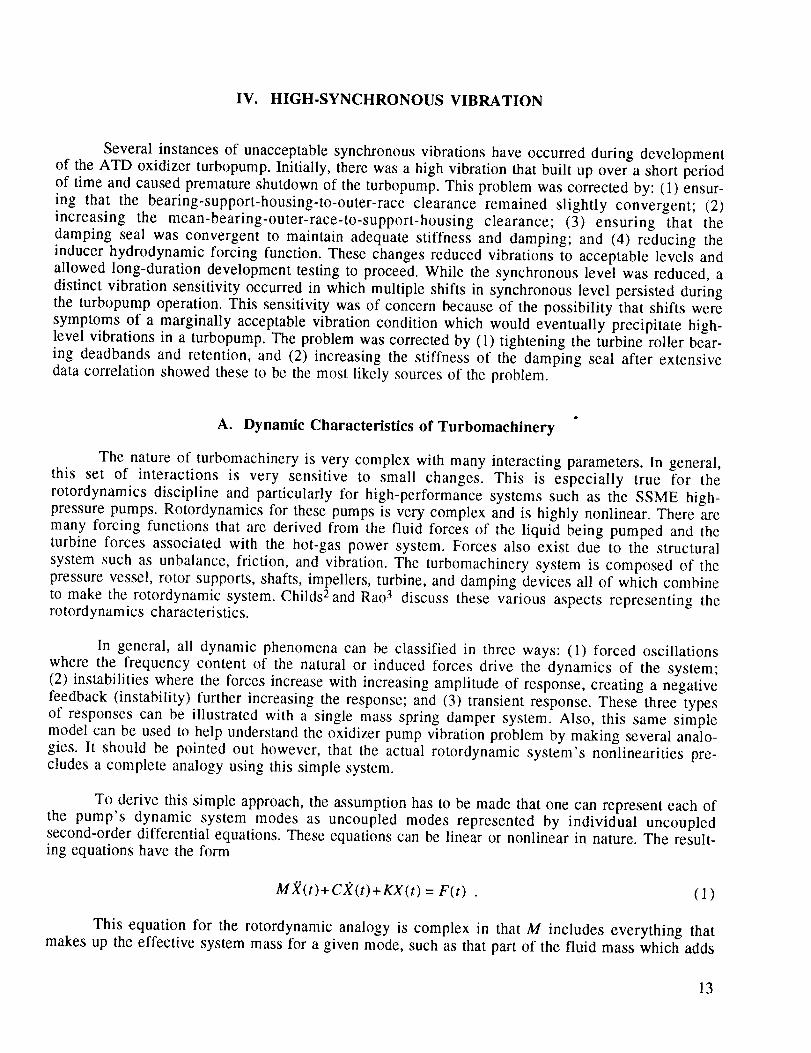
sensitivity spike. As a method of illustration, figure 39 shows the end-to-end test history of one of
the pumps showing the characteristics across time of the vibration sensitivity. However, it was
never possible with extensive simulations and hot fire data analysis to establish a firm correlationfor a resonance caused by the pump end bearing, damping seal combination.
The second source for the vibration sensitivity is the turbine end roller bearing support
changing due to thermal effects which could move a second critical mode into the operating range.
33

:_::!: :::::
: :: ::.:: !|::_::::::::• :::: ; :I
::::::.:_::::::::: i!i_iiOi!_i_i£i i_ ixl _ix _ iXi ixi i i i<i _X_ _ _ _ i _ i _ ! !X
0 • _ .... _ "_ ..... : _ ! _ i i_i i_i _ ii i i i i i i i i i ! i i i i _ _ !_ ! ! ! i i ! i i
: :::::::::::
......... _ i . _ i _ _ . ! ! ! ! ! ! ! ! ! ! ! ! !: :: .i: ::..:::::_|_ .... illegal _i_i
0 i i _ i i i i i_i i ! i i i i i i ........................... ii!ii!ii!!illi!!iii!iiiiii!i!i
iii iiili iii!il .............i i_i ixi i<i i_i i i i i !xi i<i ixi i i i_i i i i_i i ixl
:1::::':,: .... :: , .:t:::::*.l:.
::::: :i::: ::::. : I ,,:: ,. ::
i i i i i i i i i i i i i i i i i i i i i i i i i i i ! i ii i i i i i i i i i i ! i i i i i i i i i i i i i i i i i i
:1::::::::::_:::: :;:::::::::l;................. _i!_i_illi_!
................. ii i i i i i i i_i i i i i i i _i i_i i i i i i ! !! i i i ! ! i i_i i i i i _ i i i x:_ !_ i i i _ i i =..... : : ,-, , , . , , , , : igl igl i i i i i i i i .o::::::::::::::::: i!_!_!iiiillil
:::::::: ::::: : ili_!i_iiii_l!i!_!,._.._.!!i_ :::::::_:::::o_
:::i.:::::::::::. _i|_i|!ili|_|
,_ : : _ _ _ ; : i i i i ! i i i i i iXi ! i _ iXi i !_! f i i0 ! i i i i i i i i i _ i i i i i i_ _ _ _ _ _ _ i _ _ i _ _ _ _ _ _ ....
................. __i!_!i|_i!.._i:!illi|_ill :::::::::::::III. II.IIIIJ_IL.I[ LtIII. I..tL$#1
; ; : i i 7-: i i i i ! i i_i i i i : : i _ i i i i i i ! _tlili:_ll|liillml!/ ill/ill/l--ill|
1::':11 Ilil:_lll: Ii ::::litll:i
i i i_ i_i--: t i i i i !_! i I i i t i i ! ! ! i_i_ t t.... i _ " _" i : . _i i : I ' m: :
:_i t _: : t" . : : : : : l • :_. • .m: : :• t --:_ : • ._. : • : : • : : : : . : ._ : :=. _ . . i_ : • : . t , : • • : .... _0. • i,o:=,, ...... .... : :, ........ ,
: :_: .^.--i :_i t t_i i i ! i , t _ , _ cl i#_i v _ti I" i l 1 : : _ : : 1 : : _: " I :'_: i v.
• : ): :_i _:_1 I I _ l_l I: _ ki I II : I, 1 I: _: : : 1 : ;liil I )l
' w_ .... _ --- • .....
• _._.._i_i !_._ _m!>._._:_. _'=: _:_:_: : _ I_= :_:: i_ _ _i_ _: ;_:_:m:_i _:_:_:_I :_:_:o:_:_: i i_i,_i_.i : _ _i._: i _:_ _!_l_!_l.=: _I Kl_i._ !_ _i'_i_:_i : i._i_:vi_!I _ _ ii_i'=i_i_i_ _l_wi_ _i_iE_= _._ i :_i_i_i
• _. _. _',_" _" : • : : : _:_: : : _: ._: _: _t : • " : • : : • _: _:: :_: _ _._ ._ _._ _- _ _ _ m. _ _ • •• _' _ • - _,_: • _: • : _: : : : _: :'_: _: : _. _. : : :_: 0:_:
:_:_:_:m:_: ._:_._'_._:_.=-_'o: _:_:_: _.:.:_: - !_:0:_:_:=--'-- _ _ _ i'-- i _ -- _ "- v: • --. _ _ ...... : • : . -._ .....:::_t0: :'_. ::::i _: _:-:::_,:':i:::: ._._._=_-_,__ .... m: : :_:._N_ t _o. :_,_,
• _'_. ,_'_ • : ! ._'_:_. _: : : : '_: : : : : • : _:_: _: •
: .E,_. • ._: :m:o:o: :E:E:=. : : _: :o,o:o:o:.-. • : .... _: •
-- .._:_,--:_:0:0:_ --:--:_ 0:0:_ W:C: :m:-- --:--:--: : :_:_:_:_:
34

_g
n.l_..l°
GO
O_
ga
o"
I....i •
o
I¢
o
_°0
¢¢
,,¢
NSS - Nx/-_ TSH = 10
Suction Specific Speed w (NPSH + TSH) 3/4 1

9_
NSS = N'_ TSH ,. 10
Suction Specific Speed u (NPSH + TSH) 3/4 I
NSS = N_f_ TSH = 10
Suction Specific Speed -- (NPSH + TSH) 3/4 1
!

L_
Z7
0_
Z7
,.<
c
o
¢_ bo
<
e=_
e'_
O I
>O
0_ Ibo
0_
No Sync Vib
No Sync Vib
No Sync Vib
I
I
Maximum NSS Operation
Suction Specific Speed
bO
O0
010
I I I
©©>
Na_
0
"< _. '-'"
(/1_,_ Z
,-.<_..,o
<_.._°

8£
"rli.d°
>¢
t_
_=to
o
f_
0_
.¢f_
t_
t-o
O
C3_OO
Syncnr0n0us Speed - Hz
Amplitude Grms (IX)

tt%
0
II!
: 8
I
I
(XI) smJ9 oPnl!ldtuv
zH - pood S snouo.xuau_ S
0
00
0
39

Hot-fire data have shown that there is undesirable hot-gas leakage that is affecting the roller
bearing support. Special instrumentation was installed in pump build 03-2 to assess the thermalenvironment. The data showed erratic hot-gas leakage that changed the roller bearing support
temperature from the design predicted. The change in the housing temperature will alter the bearing
support fits and thus change the support stiffness. A comprehensive effort was undertaken to
provide a stable housing environment.
During this bearing solution development of the lox pump, prior to the evolution of the above
critical design review (CDR) configuration, one pump configuration, 7-2D, experienced a high-g
redline engine cutoff. This pump was being used to tune the bearing clearances, reducing theclearance in order to ensure less nonlinear bearing deadband effects. The bearing hung up, which
caused the high-g shutoff, as discussed previously, was shown to be the cause through teardown
inspection.
Since the vibration team was dissolved (solution of the high-synchronous spikes and bearing
degradation problems), the turbine-end thermal excursions have been fixed and the CDR pump con-
figurations built and tested. These pumps have not experienced any high-g spikes, and no vibration
sensitivity.
V. BEARING WEAR
An HPOTP bearing distress problem first surfaced in September 1992 when long-duration
engine testing was started after resolution of the synchronous vibration problem. The bearing which
failed was the oxidizer-cooled pump-end ball bearing of the turbopump. With one exception (whichwill be discussed later) the bearing would fail after as little as a 100 s of operation to a few thousand
seconds operation. Externally, a 2.5 ° step increase followed by a ramp increase in the coolant tem-
perature rise across the bearing was noted (figs. 40 and 41). This event was assumed to be the
bearing failure and is seen to be a discrete occurrence that does not take a long period of time to
happen. Operation after this event showed continuing wear of the bearing as evidenced in the changein posttest rotor travel. When a turbopump teardown inspection of the bearing was done, the balls
and races were found to be worn and thermally discolored, and the Salox-M ® cage showed heavy
fore/aft ball pocket wear. Comparison of the inner race surface color with test specimens heated in anoxygen environment indicated that the surface temperature reached 1,400 °F, a temperature well
beyond design intent. Figure 42 is a bar graph of the bearing life experience for several pumps
(numbers at top of bars) before the acceptable solution was implemented, showing that somebearings failed early and some ran a long time without failure.
In view of the design and development experience, the onset of the wear problem was
unexpected. The static and dynamic loads carried by the beating were kept low by careful attention
to hydrodynamic and mechanical design of the turbopump. Posttest examination of the ball tracks on
the bearing races verified that the loads were meeting the design. The bearing is cooled by approxi-mately 16 lb/s of lox flow from the preburner pump discharge. The Salox-M ® bearing cage is
designed to provide cage-to-bearing transfer film lubrication. Extensive design verification testing at
the component level of the bearing under simulated load and coolant were very successful. Severalbearings were operated to twice the 71/2 hour design life with no evidence of abnormal wear. A single
failure in the component tests was isolated to a test rig misalignment problem. A similar design
liquid hydrogen-cooled bearing used in the high pressure fuel turbopump (HPFTP) had successfully
passed component test and was showing no problems in turbopump development, even though it
runs 50-percent faster than the oxidizer pump bearing.
40

o0
0
0
_.)
_.)
00
0
?0
o'1
41
I I I I I
m
.0
0
0
0
0
0
0
U_
o_
0_-_
U_
42

§
0
I "S'_l
§
°,_
c-O
0
0
0
0
e"
0
o_
43

0
e_0
0
0
0
6
t-¢3
44

45

46

o
c
_t"o
©
__oooo ....
°,_._
o
o
o
°_..,
4?

4S

C_
c_
o
49

I I I I I
5O

8-
[,.6-
4-=I=
=a
8
ce 4
0
W
0
,. | - __
,,,,,,,,, ,,,, ,,,,,
200 400 600
Time From Start Signal (s)
Normal Bearing Coolant
Temperature Profile
i _ .t2J t I
Ddm Evel
01 , ..... ,,, .... ,,,,,
200 400
Time From Start Signal (s)
High HeatGeneration Event
60O
Figure 40.
• Radial deadband:
Clearance that allows
bearing to move axially
with rotor (± .016 °)
• Preload spring: _
Provides axial load /
needed to produce \
'adials'i"°ss---X \ J� /f._-k_ ;%;rl,'a =.ILl #/// II
f \ql, a-l=_m_--=-_'/ y \'------
A.l,_,a,,,otor / / i.----B_n_,'Tvibratory response ..... f t _na D r
Also produces radial # /'
stiffness like a bearing /
L....... Ball bearing:
Provides rotor radial support.
Desired cross-comer
Ioadpath shown
Bearing coolant flow temperature.
10
o
r_
i,
i
._ rrl
I,Ir_
[J
i r
fll
rll
11!
(i
IllS]OR': OF PEFJB r}ELr^-1 SI"IK{-S
2--[::]--02 - 3 904- 156 3---_--05 -- 2 C rlo'l - 1 -57
.5--t_--OS-2B 901 -:18
1
f
I
'7 T F N r,ll'_
1_).;- 1< 904 15,l
4--.¢_--0 ', 113 904 159
'2g ........
!
_,{1 *i (11)- I i'_Q :.'(10
......................... (_'=¢9
250 30o ;$t,O
:11M,_ sec
I
4(]0 4{,0 %()() % p-,[i
Figure 41. Bearing coolant temperature rise.
P_IGE IS
0t. lt(t (it_r!_
51

PEBB Accum Time at SSC
4500 - --
4500 - --
4500
4500
"-" 4500
4500 - -
'- 4500
4500
.$--2A,
Bearing Code:
O Still Operational
O Some Wear But May Be Used on E8
• Wear, Not Reusable
X Bearing Distress
Bearing Activity Status, (S/N)
4500
Figure 42. SSME/ATD HPOTP pump end ball bearing experience before corrective solution.
Reviewing, the life of rolling contact bearings is determined by many external factors such as
dynamic and static radial loads, axial loads, bearing misalignment, instabilities in the rotor dynamics,
lubrication, cooling and bearing geometry. Most research and engineering effort has been expended
on oil-lubricated bearings. Cryogenic rocket engine turbomachinery cannot use oil lubrication due to
the cold and the incompatible nature of the liquids being pumped. There have been major problems indeveloping adequate bearing life with lox and, to a lesser extent, liquid hydrogen-cooled bearings in
turbopumps. The primary failure mode has been bearing wear and distress. Bearing fatigue failure,
upon which the life predictions of well-designed oil-lubricated ball bearings are based, have not been
the usual failure mode for bearings cooled and lubricated with cryogenic propellants. The problems of
bearing design are compounded by the requirement that these pumps be lightweight and have a veryhigh power density. In these turbopumps, the bearing life determining mechanisms have been heat
dissipation and generation. Figure 43 shows how for a high power bearing a balance determines
whether a bearing will operate successfully or will overheat. It is possible to put all the major
parameters that influence bearing life under these two headings (fig. 44). Heat generation in the
bearing is primarily from frictional contact between component surfaces, hysteresis losses because
of cyclic stressing of the materials, and viscous fluid losses in the coolant. Heat dissipation is
through convective heat transfer to the coolant in the flooded cryogenic bearing design. It should be
pointed out that there is a strong interaction, or coupling, between heat dissipation and heat genera-
tion that is nonlinear in nature. As the heat generation exceeds the heat dissipation capacity,
52

0
',,._,
High Life
)._w Power
N_h Power
Heat Generation
Low Life
I Bearing Life = (Dissipation) - (Heat Generation) [
Low bearing life (wear) is caused by inadequateheat dissipation for a given heat generation
Heat dissipation and heat generation are coupled
independent variables
Heat generation with inadequate heat dissipation
results in excessive inner race temperature whichis the prime source of bearing wear
Figure 43. Bearing life.
i
[Cooling ]
Coef_c_ent I
I of Friction ]
I
]Lubrication I
] Salox IIOxidesl
i
I Temp. I| •
Press. I|
Temp.
I Pre
I
I
I
SurJ ice[Fin sh ]
I!
i ISupply
Distribution
Figure 44. Bearing wear parameters.
53

abrasive surface oxide formation starts, the thickness of the elastohydrodynamic film is reduced,
ball-to-cage interactions increase, inner race clearance (IRC) is reduced, prelubrication breaks
down, and cage-to-ball-to-race lubrication transfer diminishes. All of these factors further increaseheat generation, leading to what is often termed "thermal runaway" of the bearing.
Thus, a situation had evolved in which all bearings placed into service were failing within a
few hundred seconds of operation for no apparent reason. Development of the turbopump was being
delayed and significant cost increases were being incurred because of the inability to resolve the
bearing failure. At the end of 1992, development termination was threatened unless the problemcould be solved within 3 months. A team of Government and contractor specialists was formed with
a directive to take all reasonable steps to resolve the problem by the deadline. Because of the
limited time available to correct the problem, a concurrent approach was taken. Design and procure-
ment of potential fixes was undertaken based on best engineering estimates of their potential for
solving the problem. Fixes that were not viable based on increased understanding of the failures
were dropped and new designs were added. While this approach is not the most cost effective, it
does give the quickest engineering response time. The steps this team took, starting with a detailedfault tree analysis, are reviewed in the following paragraphs.
The detailed fault tree developed by the investigation team is shown in figure 8. The viable
candidate failure mechanism that devolved from the fault tree analysis were:
(1) Misalignment
(2) Prelubrication
(3) Cage instability
(4) Inadequate IRC
(5) High loads--fixed and dynamic
(6) Inadequate cooling
(7) Inadequate lubrication
(8) High ball/race heat generation
(9) Bearing material and configuration
(10) Other potential causes.
All but items (6), (7), and (8) were eventually dispositioned as not being a cause or at the
most being a secondary factor in the bearing wear. The failure scenario that most closely fit analy-ses, test results, and hardware evidence involved a combination of these three items on the list. Adiscussion of each of the mechanisms and the assessment of its involvement in the wear mechanism
follows.
54

(1) BearingMisalignment
Inspectionsof the first distressedpump-endball showedevidence of bearing misalign-ment (tilting), i.e., angular displacementbetweenthe inner and outer races.The evidencewas pro-nouncedfore andaft cagepocketwearthat will occurastheballs of themisalignedbearingspeedupand slow down as they orbit the inner race (fig. 45). These data initiated investigations tounderstandhow misalignmentmight affect bearingheatgenerationand thusbearinglife. As a result,detailedsensitivity studiesusing variousbearingcodeswereconducted.
The resultsof thesestudiesshowedthat if the bearing misalignedmore than 4 milliradians,the temperaturewould rise as the cage pocket clearancewas used up. This temperaturerise wasfound to rise to the sublimation temperatureof Salox-M® at the cage/ball interface, which couldrender the Salox-M® transfer film ineffective.This could increasethe ball-to-race friction quickly,causingpotentially large temperaturedelta T's and bearing distress.Figures 46 and 47 show thisdata. Figure 46 shows the heat in Btu's versusmilliradians. Figure 46 illustrates the cage pockettemperature,while figure 47 shows the temperaturedelta T if the friction coefficient is linearlychangedfrom Salox-M®-on-steel to steel-on-steel.
Two facts argued againstexcessivemisalignmentof the bearing. Inspections of the racetracksof bearingsafter turbopumpoperationdid not showindicationsof misalignment.A turbopumpbearing was also instrumented for outer race misalignment. These measurementsdid not showexcessivemisalignment.For thesereasons,this failure mechanismwasdiscredited.
(2) Prelubrication
As previously mentioned,therewasoneexceptionto the generalearly failure character-istic shown during turbopumpoperation.Early in the investigation, one turbopump (unit 07-2) ransuccessfullyfor over 5,000 s with no bearingdistressandmarginally acceptableball and racewear.This tended to confirm that the bearingdesignwas acceptableas demonstratedin the componenttest.This result causedan intensivestudy of the factors contributing to successfuloperationof thisbearing.Two factors stoodout: (1) it hadbeenrun for over 1,700s before high speedoperationwasundertaken,and (2) it, as was also the caseof the componentdesigndemonstrationbearings,hadnot receiveda prelubricationof the racesuntil the first 1,700s of operationwerecompleted.Inspec-tion showedthe inner raceof this bearingto be very smoothandpolishedrelative to the outer race.This is contrary to the experienceof the failed bearingwherethe innerraceshowedseveredistress.
It was also observedthat the ball track wear on the racesshowedthat some failed bearingshadswitched from outer raceball spin control to inner raceball spin control. Theory allows this tohappenwith an increasein thefriction factorat the innerraceover that at theouter raceby a factor ofthree.Thus, attemptingto isolatethe factors which maintainedthe low surfacefriction at the innerraceof this particular bearingwasgiven a greatdealof attention.Theseefforts were not successfulanda full understandingof thecharacteristicsthat madethis bearingandturbopumpunique were notachieved. Prelubrication of the bearing raceswas baselinedas an improvement that could onlyimprove bearing operation. It was also concludedthat the reversingof ball spin control was theacceleratorof the bearingdistress,not the initiator.
(3) CageInstability
All pump-end ball bearingshave shown evidence of some contact between the innerdiameter of the cage and the inner race land. This evidence could possibly be explained by an
55
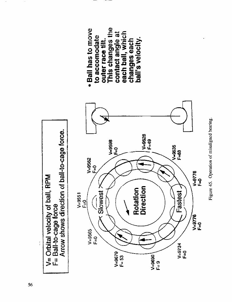
o
o
.___
t _
Om<tl II
>LL
°_,._
o
oe.a0_
©
,,4
56

I.S
_.,_o0"o
O_
:3-c_
0
i,===*
0
cT
_rq
0
M_ Cage Poc_t Su_c8 Temp, °R
i ..... ' co _ , "
Cii_ _o8_ FricdondH_, Bt_/scc (I)_' I%1 _" {: _=
_--h_......._....._......_--------_......-_ ""-" " '"" '"="
...... '........_....... ,< o_..=. ;:t__i ,.,c_ _ _. -_,-.,.cn,_.
w._ m @ e::_v.
' _ i \L., _, _ • ,.,_x_
-'I O"


unstable cage which in effect "hula hoops" during rotation. The influencing factors for the instability
are: (1) ball-to-cage pocket clearance, (2) cage balance, and (3) cage to land clearance. Other evi-dence to support the instability was the fore and aft wear on the cage pockets, which indicates
excessive movement of the balls relative to the cage. The effect of the instability would manifest
itself in cage frequencies in the dynamic data and in an increased temperature rise in the bearing.
Analysis results showed that with the existing clearances and unbalance the cage should be stable.In fact, the ball-to-pocket clearance can eventually be doubled from the baseline clearance before
instability is a problem. Examining the dynamic data for cage instability and correlating it with the
bearing coolant delta T shows that the cage frequency is pronounced only after the step event of the
delta T. During the initial slow rise of the delta T where heat generation is increasing, the cageappears to be stable. This leads one to believe that the cage frequency is a result of the accelerated
wear process and not a cause. Because of this evidence, the cage instability scenario was dismissedas not credible.
(4) Inadequate Internal Radial Clearance (IRC)
The proper design of a ball bearing requires that the internal radial clearance at operation
be sufficient to allow the balls to load against the races at the proper contact angle and provide suffi-
cient margin against a thermal or mechanical loss of radial clearance. Inadequate IRC allows theball-to-race contact angle to be less than design (ball track will be low on the inner race). This
condition promotes increased heating of the balls and inner race due to higher contact stresses, andprovides less margin against thermal runaway.
Examination of the inner races of the units which did not fail (low time units) showed that the
ball tracks were at the proper contact angle. Failed units had ball tracks which were not too low;
however, the track was very wide--some nearly touched the inner race high shoulder comer. This is
believed to be due to post-accelerate wear damage and not an indication of the as-built or pre-event
contact angle. Based on this evidence, the inadequate IRC scenario was judged as not credible.
(5) High Bearing Loads: Fixed and Dynamic
While the inspections of distressed bearings did not show overt signs of either highradial or axial loading, the unknowns in the design and our previous experience with ball bearings in
cryogenic turbopumps did not allow us to immediately close out overload as a potential failure mech-
anism. In the turbopump design, the bearing cartridge must move axially in response to all operating
point changes to ensure acceptable axial thrust balance. The cartridge (sleeve) has tight clearances,
with the pump housing making a design that could potentially bind and introduce high axial loads into
the bearing. In addition, the uncertainty in the hydrostatic loads acting on the rotor of a high pressureturbopump can be very large and as yet cannot be accurately predicted for a design. Dynamic loads
on the bearing, especially in a turbopump which has exhibited high vibration sensitivity, are always abearing load concern.
Strain gauges were mounted on the pump-end ball bearing preload spring on several devel-
opment turbopumps to give a direct reading of the axial static and dynamic loads. They showed that
the bearing axial load was as predicted and that the bearing was moving axially as required to
accommodate pump operating points changes. The axial dynamic loads measured were very low. Asubsequent turbopump with radial position measurements of the bearing sleeve deadband showed
the sleeve to be moving radially, which confirmed that the radial loads were close to design. Againthe dynamic load indications as seen by these gauges were low. Based on these data along with
59
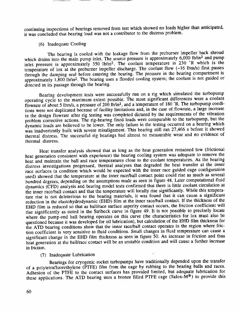
continuinginspectionsof bearings removed from test which showed no loads higher than anticipated,it was concluded that bearing load was not a contributor to the distress problem.
(6) Inadequate Cooling
The bearing is cooled with the leakage flow from the preburner impeller back shroudwhich drains into the main pump inlet. The source pressure is approximately 6,000 lb/in 2 and pump
inlet pressure is approximately 350 Ib/in 2. The coolant temperature is 230 OR which is the
temperature of lox at the preburner impeller discharge. The coolant flow (-16 Ibm/s) first passes
through the damping seal before entering the beating. The pressure in the bearing compartment is
approximately 1,800 lb/in 2. The bearing uses a flooded cooling system; the coolant is not guided or
directed in its passage through the bearing.
Bearing development tests were successfully run on a rig which simulated the turbopump
operating cycle to the maximum extent possible. The most significant differences were a coolantflowrate of about 5 Ibm/s, a pressure of 200 lb/in 2, and a temperature of 180 °R. The turbopump condi-
tions were not duplicated because of facility limitations and, in the case of flowrate, a large increase
in the design flowrate after rig testing was completed dictated by the requirements of the vibration
problem corrective actions. The rig-bearing fixed loads were comparable to the turbopump, but the
dynamic loads are believed to be lower. The only failure in the testing occurred on a bearing which
was inadvertently built with severe misalignment. This bearing still ran 27,466 s before it showed
thermal distress. The successful rig bearings had almost no measurable wear and no evidence ofthermal distress.
Heat transfer analysis showed that as long as the heat generation remained low (frictionalheat generation consistent with experience) the bearing cooling system was adequate to remove the
heat and maintain the ball and race temperatures close to the coolant temperatures. As the bearing
distress investigations progressed, thermal analyses that degraded the heat transfer at the innerrace surfaces (a condition which would be expected with the inner race guided cage configuration
used) showed that the temperature at the inner race/ball contact point could rise as much as several
hundred degrees, depending on the assumptions made as seen in figure 48. Later computational fluid
dynamics (CFD) analysis and bearing model tests confirmed that there is little coolant circulation at
the inner race/ball contact and that the temperature will locally rise significantly. While this tempera-ture rise is not deleterious to the bearing materials, it was found that it can cause a significant
reduction in the elastohydrodynamic (EHD) film at the inner race/ball contact. If the thickness of the
EHD film is reduced so that as ball/race surface asperity contact occurs, the friction coefficient will
rise significantly as noted in the Stribeck curve in figure 49. It is not possible to precisely locatewhere the pump-end ball bearing operates on this curve (the characteristics for lox must also be
questioned because it was developed for oil lubrication), but calculation of the EHD film thickness forthe ATD bearing conditions show that the inner race/ball contact operates in the region where fric-
tion coefficient is very sensitive to fluid conditions. Small changes in fluid temperature can cause a
significant change in the EHD film thickness as seen in figure 50. An increase in friction and thus
heat generation at the ball/race contact will be an unstable condition and will cause a further increasein friction.
(7) Inadequate Lubrication
Bearings for cryogenic rocket turbopumps have traditionally depended upon the transferof a polytetrafluorethylene (PTFE) film from the cage by rubbing to the bearing balls and races.
Adhesion of the PTFE to the contact surfaces has provided limited, but adequate lubrication forthese applications. The ATD bearing uses a bronze filled PTFE cage (Salox-M ®) to provide this
60

Z0
//
\ i =
,00
en
=t×
n- n"co
Z0I-.
Z >-_.}-.}.-
u.J ,_
0
00
e"
<
0
r..)
_6
61

=L
oC..)
LEo
t.3
o
o.001
Figure 49.
t
I
JIJ
),<<t ! )._ITO 3)
I
t I
I _"SURFACE ROUGHNESS It
II _ >31'010 )_:,S
-MIC
lIII1I
IJ , ,
too
Viscosity _ x Velocity VPressure P
Stribeck curve (coefficient of friction versus viscosity by velocity/pressure).
o¢
.q
#f.14
3.00 10 "6
2.50 10 .6
2.00 10-6
1.50I0"6
l.O0I0"6
5.00 10.7
150
8-113 • ADORE Results - EHD model includes changes(END film and Inner Race to Iox viscosity with temperature and pressure in
Injection) the contact zone. Empirical equation developed-_ _ . for oil films.
...... O Outer Race ......" _1 1...... _ _ J ! *Contact film temps are assumed to be equal the
: _ |-----.e-- inner.a= ] } max inner race temperature.
• ._]'-. ] __:Ty.pical OR ...J............• lO4O/. RPL.
• _. ",o /./ FIlm • For partial EHD film, the race to ball friction
i _ ",, IP i [ I factor =.04 and the ball to cage friction factor
• "-'qr .. [ _ ! i ij \I -., I l i
3-IG / ....S;"$_.........7::::...........l...................i...................i....................
(EHD film_, - I _ ""! ...... Asperity HeightNo Injection j ! __$'-_" 'i ......... e On Inner Race = 1.E-6 inL;oollng) .,.=_=====_==..,=,,,==......=m..,=..,...,...,.=.=-=,,.,...,.,..,.
t ! i _All Other Pumps.... i .... i .... i,,, (NoEHD) ,I ....
200 250 300 350 400 450 500 550
Contact Film Temperature, °R
Figure 50. Lox EHD film thickness analysis.
62

lubrication function. Inspection of bearings from the rig testing showed that an adequate film of PTFE
was being transferred as evidenced in the copper shading of the ball track on the races. Inspection ofbearings from the early turbopump tests substantiated these results, and it was concluded that thelubrication intent was being met.
After the onset of the bearing distress problem, a prelubrication process for initially the inner
race and later for both races was developed. Prelubrication was initiated to insure that an adequatelubrication film was present at the ball/race contact from the start of turbopump operation. The raceswere burnished with a Salox-M ® block on the race contact surfaces.
During the failure investigation, the adequacy of the Salox-M ® lubrication was questioned
and several efforts were initiated to further improve the prelube and to provide a low speed run-in ofthe bearing. No definitive answers on the effectiveness of the prelube or on the worth of the run-in
were reached. It was concluded that the worth of the prelube was most modest. The low speed run-in was dropped because of inconclusive test results.
As previously noted, the EHD film lubrication is significant in the successful operation of the
ATD bearing. Again, small changes in lox properties can be shown to dramatically change the friction
factor as seen in figure 49. The increased coolant temperature from the successful rig tests to
turbopump would cause a significant decrease in the EHD film thickness, and thus, a tendency foroperation in the boundary lubrication region (fig. 49). Traction tests run at MSFC showed a friction
factor of less than f = 0.1, with conditions simulating the pump-end ball bearing, except that normalboiling point oxygen was used as a coolant. When the test was repeated with higher loads and lowerspeeds, the friction factor increased to f = 0.2. This is a clear indication of a sensitive EHD film
contributing to the rig coefficient of friction.
Based upon these results, it was concluded that bearing distress could not be correlated to
any breakdown or failure of the cage transfer film. The effectiveness of the transfer film is, however,
open to question, and it is the opinion of many of the team members that it contributes little to thebearing lubrication.
(8) High Ball/Race Heat Generation
Excessive heat generation, which by itself or in conjunction with another failure mecha-nism, was considered as a potential cause of the thermal distress seen on the balls and races. Heat
is generated by relative motion between the ball and races at the point of contact. The heat gener-ated is thus a function of the friction factor of the materials, the contact loads, and bearing geometry,
which will contribute in establishing the magnitude of relative motion. As noted earlier, the bearingloads were determined to be within the design limits. The bearings were determined to be as
designed, and the load tracks on bearings that had not failed showed that the bearings were operat-
ing as designed geometrically. The friction factor at the contact is set by the surface finish and the
EHD film established. The bearing balls and race contact area were being finished to < 1 tin, a value
consistent with low rolling friction operation. The EHD film, as previously discussed, was believedto be marginal and for this reason excessive heat generation was a viable failure mechanism.
A simplified fault tree that concentrates on the viable interrelated failure mechanisms is
shown in figure 44. There are several paths through this fault tree leading to a distressed beating.The bearing team was unable to isolate the failures to a single mechanism. It is uncertain that thereis a unique mechanism which will fit all of the failures. A combined mechanism with the several ele-
ments making differing contributions depending on the circumstances may be quite appropriate.
63

The fault treeapproachservedthis failure investigationwell. Themost difficult and time-con-sumingpart of the investigationwasdevelopingdatato closeout severalbranches of the fault tree.
(9) Bearing Material and Configuration
The other main emphasis of the investigation was in the area of the bearing material and
bearing configuration. Bearing materials were considered to play a minor role in the failure cause; the
heavier steel balls with their friction and heat transfer characteristics could have been part of the
cause along with improper coolant. Bearing configuration characteristics that were studied and ruled
out as a primary cause were ]RC, inner race guided cage, cage pocket-to-ball clearance, and balldiameter. As solutions to the bearing distress problem were explored, all these areas were used to
improve margins as well as solve the problem cause. The final configuration has outer race guided
cage (fig. 51), stiffened housing, silicon nitride balls, lower preload spring, larger ball-to-cage pocket
clearances, and auxiliary cooling (fig. 52).
Outer Race Piloted Cage Inner Race Piloted Cage
Figure 51. PEBB outer race piloted cage.
(10) Other Potential Causes
The team methodically pursued many other causes from balance position control
authority, axial preload, high-radial load, surface sliding, plastic deformation, manufacturing, plus theother items discussed.
64

Original Cooling (235 "R) Auxiliary IR Cooling (235 + 195 "R)
IR Guided OR GuidedIR Guided
t'Baseline)OR Guided
w / cutback IF]
--y ........ -_
_J4___t___
t
Figure 52. SSME/ATD HPOTP bearing configuration.
(11) Conclusion
The bearing problem was caused by excessive ball/inner race friction which in turn was
caused by inadequate lubrication.
The bearing degradation scenario is:
(1) The basic cause of the problem is high heat generation and poor heat dissipation.
(2) Inadequate coolant temperature and distribution are the prime mechanisms for the heat
dissipation. Heat generation is also improved by increasing the thickness of the EHD
film (which reduces the ball/race contact coefficient of friction) and enhancing theSalox-M ® transfer and retention.
(3) The EHD film generated by cold lox is very sensitive to:
(a) Coolant temperature (viscosity)
(b) Surface finish
(c) Beneficial oxides created by cold lox
(d) Contact pressure
(e) Velocity.
A breakdown of the EHD film and loss of the Salox-M® transfer film caused by higher temperaturelox is believed to be the trigger mechanism that initiates the rapid wear phenomenon.
65

(4) The ball raceway control is a secondaryevent caused by the sudden increase incoefficient of friction at the inner race,and contributesto the rapid rise in delta T andbearing wear.
(5) The use of silicon nitride ball material lowers the heat generation and improves heat
transfer, enhancing bearing life. Silicon nitride balls also minimize the potential for break-down of the EHD film and Salox-M ® transfer film and reduces the loads due to lower
mass. The ball material can also tolerate much higher temperatures than can 440C steelballs.
(6) The success of unit 7-2 is explained by the low power run-in operation early in the test-ing of its bearing. Operation at 65-percent RPL results in a 40 °R reduction in coolant
supply temperature, which is highly beneficial to creating the improved surface finish
before extended operation at high power with the higher heat generation.
The corrective actions to eliminate wear are: to improve the coolant supply at the inner race
ball contact, to use an outer race guided cage, and to use silicon nitride balls. In development of the
corrective measures, the silicon nitride bearing balls and the outer race guided cage were introduced
into the turbopump together. All turbopumps with these two modifications ran successfully andshowed no measurable ball, race, or cage wear when inspected. Subsequently, the inner race ball
contact cooling modification was added and again pumps with the three changes have operated with
no wear. A single turbopump was built with only the outer race guided cage and inner race ball con-
tact cooling modifications. The bearing was found to be worn and thermally distressed after 400 s of
operation. Bearing coolant temperature rise data indicate the distress started after only 40 s of
operation. Based upon this result, it must be concluded that the cooling improvements of themselveswere inadequate to correct the problem. The silicon nitride ball characteristics, high elasticity, low
centrifugal forces, reduced race contact heat generation, higher thermal conductivity, and a lower fric-
tion coefficient, when used with metal races, are crucial to successful operation in the ATD HPOTP
application. No additional work was undertaken in this program to further understand the contribu-
tion to successful bearing operation of each of the design improvements. Based on this experience
and several previous unsuccessful attempts to develop lox cooled baring, dependence on only a
transfer and/or an EHD film is too marginal and uncertain for successful bearing operation. The ben-efits of the silicon nitride balls are required.
Bearing technology and turbomachinery understanding were certainly advanced. The team's
final fix for the bearing problem is:
(1) Silicon nitride balls with steel races
(2) Outer race-guided cage
(3) Larger ball-to-cage pocket clearances
(4) Inner race prelubrication only
(5) Colder coolant directed to inner race.
These changes were completely successful in correcting the wear problem. No bearing wear
has been observed since these incorporations.
66

The team did pursueother solutionssuch as better prelubrication, and hydrostatic damperseal bearings.Although the hydrostaticdamperseal bearinghad manymerits, it is probably a goodbearingfor thefuture.
Even if thebettercoolantwas fundamentalto thebearingdistre_ solution, dependingon it tocreateEHD film is not prudent.Therefore,it is mandatorythat thebenefitssilicon nitride balls bringbepartof thesolution in order to guaranteebearinglife.
VI. OVERALL CONCLUSION/SUMMARY
The rotordynamics of high-performance turbomachinery are a very complex, nonlinear system
composed of the pressure vessel and rotor support system, the hot-gas turbine drive system, the
cryo-liquid pump system, system damping devices, and the bearings. The hot gas and hydroforces
can be both periodic forcing functions and unstable (negative damping sources). Because of the high-performance requirements and the weight/volume constraints, there is a very fine tuning (balancing
act) between performance requirements and rotordynamic characteristics. This means that sophisti-
cated analysis tools, component tests, and a comprehensive hot-fire margin test program should be
established. Due to the analytical complexity and the inability to properly quantify forces such ashot-gas environments, hydro environments, structural characteristics, bearing characteristics, and
only limited analytical verification (trend/sensitivity prediction only) the margin test program ismandatory.
The solution to the ATD LO2 turbopump problems were possible only because of the fore-
sight of NASA leadership over the years to build test facilities (air and water flow, propulsive),
analysis technology in bearings, heat transfer, rotordynamics and CFD, bearing materials develop-ment, and bearing lubrication. This includes MSFC development as well as the Pratt & Whitney E-8test stand.
In future systems, it is highly desirable that the dual support system (ball bearing/damping
seal) be replaced with either a hydrodynamic damping bearing or foil bearing, eliminating the mainsource of nonlinearities or move the damping seal and provide system damping at another location--
possibly using a different source which allows full development of the ball bearing for stiffness
potential. The damping seal hydro bearing is unique in that it simultaneously provides both dampingand stiffness.
The only total answer to what is transpiring in a turbopump is found by testing in pump
stands or engine systems with adequate data obtained by special instrumentation and posttesthardware inspection. In the final analysis, the hardware has the answer, our job is to read it. Work
needs to be continued to accurately provide the hot gas and hydroforces characteristics so that the
analytical models can be more heavily depended on for design verification and operations. Betterinstrumentation needs to be developed to verify these forces and determine in hot fire actual rotorresponses.
Bearing technology development must continue. The silicon nitride ball bearing technology
saved the ATD program. It is certainly a lesson learned that new programs are highly dependent onthe technology programs. The same is true of special test facilities. These were critical in the
vibration and bearing degradation solutions: (1) the E-8 hot-fire pump test, (2) MSFC bearingtesters, and (3) MSFC cold-flow facilities.
67

It is very important that the designand the manufacturingprocessallow very quick changesin order to properly evaluate parametersensitivities and cause/solutionhardware characteristics.This ability allowed the teamto accomplishits mission.
Sensitivity analysis as well as off-nominal testing are key to understandingproblems andarriving at solutions. This coupleswith the proven approachof searchingfor deviation and theireffects. Playing the two togethershowsunderstandingof problem.
For future programs,sensitivity analysisandtesting (cold flow, dynamic,and hot fire) shouldbedoneearly in theprogramto eliminatemostof the problemsdownstream.It is doubtful, however,that this would have caught the bearing wear problem; but, it would have certainly eliminated thevibrationproblem.
The use of a concurrent engineering team in conjunction with the use of formal fault trees is
mandatory for cause identification and problem resolution. The team members' selection is critical in
that teaming brings no magic elixir to the table, thus the team is no stronger than the skills of the
team members. This implies that organizations must vigorously develop the total person of its per-sonnel.
All future systems should be designed with the goal of robustness. 15
Silicon nitride balls provide substantial margins to the ball beating life.
Through the results of the team's efforts, it is concluded that the ATD LO2 turbopump is
acceptable for certification from both beating life and vibration sensitivities and high-g vibration.However, for management of the pumps operationally requires that an extensive vibration database
of both ground and flight test be maintained.
68

.
2,
,
4.
.
.
.
.
11.
12.
13.
14.
REFERENCES
Biggs, R.E." "Propulsion System Failure Analysis-A Methodology." AIAAJSAE/ASME/
ASEE 28th Joint Propulsion Conference and Exhibit, July 6-8, 1992, Nashville, TN, pp. A1492-3796.
Ehrich, F.F., and Childs, D.: "Self-Excited Vibration in High-Performance Turbomachinery."Mechanical Engineering, May 1984, pp. 66-79.
Rao, J.S.: "Rotordynamics." Second edition, J. Wiley, 1991.
SSME Alternate Turbopump Development Program, Supplemental Report HPOTP PEBBInvestigation, United Technologies, Pratt & Whitney.
Ryan, R.S., Gross, L.A., Mills, D., and Mitchell, P.: "The Space Shuttle Main Engine LiquidOxygen Pump High-Synchronous Vibration Issue, The Problem, The Resoluti.on Approach, theSolution." AIAA Paper 94-3153, June 1994.
Huzal, D., and Huang, D.: "Modern Engineering for Design of Liquid Propellant RocketEngines." AIAA 1992, ISBN 1-56847-43-6111-147.
Csomor, A., Faulkner, C., and Ferlite, F.: "ALS Turbomachinery Technology.'" SAE Inter-national Aerospace Technology Conference and Exposition, Long Beach, CA, October 1--4,1990.
Ehrich, F.F.: "Shaft Whirl Induced by Rotor Internal Damping." Journal of Applied Mechanics,June 1964.
von Pragenau, G.: "Damper Seals for Turbomachinery." NASA TP-1987, March 1982.
Childs, D.W., and Kim, C.H.: "Testing for Rotordynamic Coefficients and Leakage: Circumfer-entially-Grooved Turbulent Annular Seals." Proceedings of the IFToMM International Confer-
ence on Rotordynamics, Tokyo, Japan, September 1986, pp. 609-618.
Childs, D.W., and Kim, C.H.: "Test Results for Round-Hole Pattern Damper Seals: OptimumConfigurations and Dimensions for Maximum Net Damping." ASME Transactions, Journal of
Tribology, vol. 108, October 1986, pp. 605-611.
Matthew, E.K.: "Solving Subsynchronous Whirl in the High Pressure Hydrogen Turbo-machinery of the SSME." AIAA Journal of Spacecraft and Rockets, vol. 17, No. 3, Article No.78-1002R, June 1980.
Childs, D.W., and Kim, C.H.: "Analysis and Testing for Rotordynamic Coefficients of Turbulent
Annular Seals with Dircctionally Homogeneous Surface-Roughness Treatment for Rotor andStator Elements." ASME Journal of Tribology, vol. 107, July 1986, pp. 298-308.
Ryan, S.G.: "Limit Cycle Vibrations in Turbomachinery." NASA Technical Paper 3181,December 199 I.
15. Ryan. R.S." "Robustness." NASA Technical Paper 3336, March 1993.
69

BIBLIOGRAPHY
Metals Handbook Ninth Edition, Volume II, Failure Analysis and Prevention, Failures of Rolling-
Element Beatings, pp. 490-514.
Bacht, D.G., Hawkins, L.A., Scharrer, J.K., and Murphy, B.T.: "Suppression of SubsynchronousVibration in the SSME HPFTP." Presented at the Sixth Workshop on Rotordynamic Instability
Problems in High Performance Turbomachinery, College Station, TX, May 1990.
Black, H.F. and Jenssen, D.N.: "Dynamic Hybrid Properties of Annular Pressure Seals." Journal of
Mechanical Engineering, vol. 184, 1970, pp. 92-100.
Black, H.F., and Jenssen, D.N.: "Effects of High Pressure Ring Seals on Pump Rotor Vibrations."
ASME Paper No. 71-WA/FE-38, 1971.
Black, H.F.: "'Effects of Hydraulic Forces in Annular Pressure Seals on the Vibration of Centrifugal
Pump Rotors." Journal of Mechanical Engineering Science, vol. 11, No. 2, 1969, pp. 208-213.
Bursey, R.W., et al.: "'Incorporation of Silicon Nitride Rolling Elements Into the Pratt & Whitney
High Pressure Oxidizer Turbopump for the Space Shuttle Main Engine." Conference onAdvanced Earth-to-Orbit Propulsion Technology, May 1994.
Childs, D.W., and Garcia, F.: "Test Results for Sawtooth Pattern Damper Seals: Leakage and
Rotordynamic Coefficients." ASME Journal of Tribology, vol. 109, January 1987, pp. 136-143.
Childs, D.W.: "The Space Shuttle Maine Engine High Pressure Fuel Turbopump Rotordynamic
Instability Problem,, ASME Paper 77-GT-49, 1976.
Den Hartog, J.P.: "Mechanical Vibrations." McGraw Hill Book Co., New York, NY, 1956.
Dillis, M.K.: "Development and Application of Cooling Injection for the Pratt & Whitney High
Pressure Oxygen Turbopump for the Space Shuttle Main Engine." Conference on Advanced
Earth-to-Orbit Propulsion Technology, May 1994.
Janney, J.R.: "Guide to Investigation of Structural Failures." American Society ot ISivil Engineers,New York, NY, 1979.
Jenssen, D.N.: "Dynamics of Rotor Systems Embodying High Pressure Ring Seals." Ph.D.Dissertation, Harlot-Watt University, Edinburgh, Scotland, July 1970.
Kim, C.H., and Childs, D.W.: "Analysis for Rotordynamic Coefficients of Helically, Grooved
Turbulent Annular Seals." ASME Transaction Journal of Tribology, vol. 109, January 1987, pp.136-143.
Lomakin, A.: "Calculation of Critical Speed and Securing of Dynamic Stability of the Rotor of
Hydraulic High Pressure Machines With Reference to Forces Arising in the Seal Gaps."
Energomashinostroenle, vol. 4, April 1958, pp. 1-5.
70

Marmol, R.A., Smalley, A.T., and Tecz, J.A.: "Spline Coupling Induced NonsynchronousRotorVibrations.'" ASME Paper79-DET-60, September1979.
McCarty, J., Murphy, J.M.: "An Assessmentof Liquid Propulsion in the United States." AIAAPaper,July 1989.
Mitchell, J.P., and Prive, J.L.: "Space ShuttleMain Engine (SSME) Alternate Turbopump Designand Development." 43rd Congressof the International AstronauticalFederation,WashingtonDC, August 1992.
Nolan, S., Hibbs, R., and Genge,G.: "Hot Fire Testing of a SSME HPOTP With an AnnularHydrostatic Bearing." AIAA Paper93-2358,1993.
O'Hara, K.: "Liquid PropulsionSystemReliability, Design for Reliability." AIAA Paper 89-2428,July 1989.
Petroski,H.: "Design Paradigms,CaseHistoriesof Error and Judgmentin Engineering." CambridgeUniversity Press,1994.
Pugh,S.: "Total Design." Addison-WesleyPublishingCo., New York, NY, 1991.
Pye,D.: "The Natureof Design."ReicholdBookCorporation,New York, NY, 1969.
Rieger,N.: "Balancing of Rigid andFlexible Rotors."The Shockand Vibration Information Center,USA Dept. of Defense,1986.
Roseau,M.: "Vibrations in MechanicalSystems."Springer-Varlay,New York, NY, 1984.
Scharrer, J., and Nunez, D.: "The SSME HPFTP Wavy Interstage Seal: Part I-Seal Analysis."Machinery Dynamics-Applications and Vibration Control Problems, ASME Pub. DE-vol. 18-2,1989, pp. 95-100.
Scharrer, J., and Nelson, C.: "Rotordynamic Coefficients for Partially Roughened Pump AnnularSeals." ASME Journal of Vibrations and Acoustics, vol. 113, No. 2, 1991, pp. 240-244.
Scharrer, J., and Nelson, C.: "Rotordynamic Coefficients for Partially Tapered Annular Seals: Part I--
Incompressible Flow." ASME Journal of Tribology, vol. 113, No. 1, 1991, pp. 48-52.
Scharrer, J., Rubin, N., and Nelson, C.: "The Effects of Fixed Rotor Tilt on the Rotordynamic
Coefficients of Incompressible Flow Annular Seals." ASME Journal of Tribology, vol. 115, No.3, 1993, pp. 336-341.
Scharrer, J., Tellier, J., and Hibbs, R.: "A Study of the Transient Performance of HydrostaticBearings: Part I--Test Apparatus and Facility." STLE Paper 91-TC-3B-I, 1991.
Scharrer, J.K., Hibbs, R.I., and Nobs, S.A.: "Extending the Life of the SSME HPOTP Through theUse of Annular Hydrostatic Bearings." AIAA Paper 92-3401, July 1992.
Spanyer, K.: "Characteristics Pertaining to a Stiffness Cross-Coupled Jeffcott Model." ASME Paper85-DET-144, September 1985.
71

Wallace,P.J.:"The Techniqueof Design." Sir IsaacPitman& SonsLtd, London,England,1952.
Zarestsky,E.: "Life Factorsfor Rolling Bearings."STLE PublicationSP-34,t992.
72 _.u s. GOVERNMENT PRINTING OFFICE 1995 633--109 / 20041

Form Approved
REPORT DOCUMENTATION PAGE OMaNo 070_Ora8
Public reDortlng burden for thi_, coHec_ton of _nformatlon ,s _tlmated to average 1 hour Oef reslx)nse, including the time for reviewing instructions, searching existing data sources.gathering and rnamtammg the data needed, and completing and reviewing the collection of reformation. Send comments regarding this Durden estimate or any other asoect of this
collocation of information, .ncludJng suggestions for reducing th*s ic>urden, tO Washington He_cluar_e_ Service_. Oirec'tOrate _or Information ODerations and RelDorts. 1215 Jefferson
Davis Highway, Su*te 1204. Arlington. VA 22202-4302, and to the Office of Management and BUdget. PaDerwork Reduction Proje_ (0704-0188), Washington, DC 20503.
1. AGENCY USE ONLY (Leave blank) 2. REPORT DATE 3. REPORT TYPE AND DATES COVERED
May 1995 Technical Paper41. TITLE AND SUBTITLE $. FUNDING NUMBERS
Developmental Problems and Their Solution for the Space Shuttle
Main Engine Alternate Liquid Oxygen High-Pressure Turbopump:Anomaly or Failure Investigation the Key
§. AUTHOR(S)
R. Ryan and L.A. Gross
7. PERFORMING ORGANIZATION NAMEtS) AND ADDRESS(ES)
George C. Marshall Space Flight Center
Marshall Space Flight Center, Alabama 35812
9. SPONSORING/MONITORING AGENCY NAME(S) AND ADDRESS(ES)
National Aeronautics and Space Administration
Washington, DC 20546
8. PERFORMING ORGANIZATIONREPORT NUMBER
I"I-780
10. SPONSORING / MONITORINGAGENC%/ REPORT NUMBER
NASA TP-3553
11. SUPPLEMENTARYNOTES
Prepared by Structures and Dynamics Laboratory, Science and Engineering Directorate.
12a. OISTRIBUTION / A VAILARILITY STATEMENT
Unclassified--Unlimited
Subject Category 20
t2b. _STRIBUTION CODE
13. ABSTRACT (Maximum 200 words)
The space shuttle main engine (SSME) altenuite high-pressure liquid oxygen pump experienced synchronousvibration and ball bearing life problems that were program threateuing. The success of the program hinged on the abilityto solve these development problems. The design and tl_ solutions to these problems are engirded in the lessons learnedand experiences from prior programs, technology programs, and the ability to properly conduct failure or anomalyinvestigations. The failure investigation determines the problem cause and is the basis for recommending designsolutions. For a complex problem, a comprehensive solution requires timE formal investigation procedures be used, in-cluding fault trees, resolution logic, and action items worked through a concurrent engineering-multidiscipline team. Thenormal tendency to use an intuitive, cut-and-try approach will usually prove to be costly, both in money and time, andwill reach a less than optimum, poorly understood answer. The SSME alternate high-pressure oxidizer turbopump devel-opment Ires had two complex problems critical to program sucoess: (1) higla syockronous vibrations and (2) excessiveball bearing wear. This paper will use these two problems as examples of this formal failure investigation approach. Theresults of the team's investigation provides insight into the complexity of the turbomaehinery technical discipline inter-acting/sensitivities and the fine balance of competing investigations required to solve problems and guarantee programsuccess. It is very important to the solution Im3cess that maximum use be made of the resources that both the contractorand Government can bring to the problem in a supporting and noncompeting way. There is no place for the not-invented-here attitude. The resources include, but are not limited to: (1) specially _ professionals, (2) supportingtechnologies, (3) computation codes and capabilities, and (4) test and manufacturing facilities.
L14. SUBJECT TERMS
Turbopump, rotordynamics, vibration, bearings
17. SECURITY CLASSIFICATION 18. SECURITY CLASSIFICATION 19. SECURITY CLASSIFICATION
OF REPORT OF THIS PAGE OF ABSTRACT
Unclassified Unclassified Unclassified
NSN ZS40-O1-280-S500
15. NUMBER OF PAGES77
16. PRICE CODE
A05
20. LIMITATION OF ABSTRACT
Unlimited
Standard Form 298 (Rev. 2-89)


National Aeronautics and
Space Administration
Code JTT
Washington, DC
20546-0001
Official Business
Penalty for Priz_te Use, $300
Postmaster: If Undeliverable (Section 158 Postal Manual), Do Not Return