p rogressive e ngineering i nc
TRANSCRIPT

58640 State Road 15 Phone: 574-533-0337
www.p-e-i.com
Goshen, IN 46528 -Fax: 574-533-9736 -
Progressive Engineering Inc.
3/12/2013 -
6/2/2016 - Revised page 2 section 2 - code revision dates.
Added Michigan Residential Code reference to Section 2
Revised page 2 section 3 - address change.
Revised on5/6/2011
I-STAIR SYSTEMS, INC.
i18gs, i20gs and trg45 I-Stair BracketConcentrated Load Testing
3/11/2011
This test report contains Seventeen (17) pages, including the cover sheet. Any additions to, alterations of, or unauthorized use of excerpts from this report are
expressly forbidden.
2011-404
1. TITLE
2. OBJECTIVE
1. 2.3.
3. TESTED FOR
I-Stair Systems, Inc.6548 Center Industrial Dr.Jenison, MI 49428
4. TESTING ORGANIZATION
58640 State Road 15Goshen, IN 46528www.p-e-i.com
5. TESTING PERSONNEL Laboratory Manager - Jason R. HoldemanProject Manager - Jacob Bontrager
All of the tests were witnessed by Mike Prins of I-Stair Systems, Inc.
6. TESTING EQUIPMENT
- Load Cell (PEI No. 465)
- Data Acquisition System (PEI No. 566)
This test report pertains only to the specimens tested. It remains the soleresponsibility of the manufacturer to provide a product consistent to that whichwas tested.
Progressive Engineering Inc.
See IAS Evaluation Report No. TL-178 for ISO 17025 Accreditation.
- Linear Transducers (PEI No. 648, 653, 731)
2015 Michigan Residential Code, Table R301.5 (Stairs), Note c2012 IBC, Table 1607.1, Note F
ICC-ES AC174 §4.1
To verify the step brackets and the tread riser gusset can withstand the forcerequired by the codes listed below. Secondly, to verify the use of tread and risermaterials.
i18gs, i20gs and trg45 I-Stair Bracket Concentrated Load Testing
Rev. 6/2/2016 2 of 17 PEI Report No. 2011-404

7. TEST SPECIMEN
8. TEST SET-UP
9. TEST PROCEDURE
10. TEST RESULTS
See the attached data pages for details.
The load was applied to 850 lbf, which is more than 2.5 times the 300 lbfrequirement. Load was applied at a uniform rate through the 2" by 2" loadingblock until the desired load was reached. The load was increased until a failurewas attained at the final test location, at the direction of the client.
The test specimen was built by I-Stair Systems Inc., and was verified by PEI personnel to the attached drawings.
The i18gs I-Stair Brackets consisted of triangular shaped galvanized steel with atriangular shaped cut-out in the center. The average measured thickness was.046". Two (2) 1" wide tabs, one (1) located on each side of the triangle, werefolded at a 90° angle and fastened to the stair tread and the other to the stairriser. See attached drawing B2 for details.
The i20gs I-Stair Brackets consisted of triangular shaped galvanized steel with atriangular shaped cut-out in the center. The average measured thickness was.036". Two (2) 1" wide tabs, one (1) located on each side of the triangle, werefolded at a 90° angle and fastened to the stair tread and the other to the stairriser. See attached drawing B3 for details.
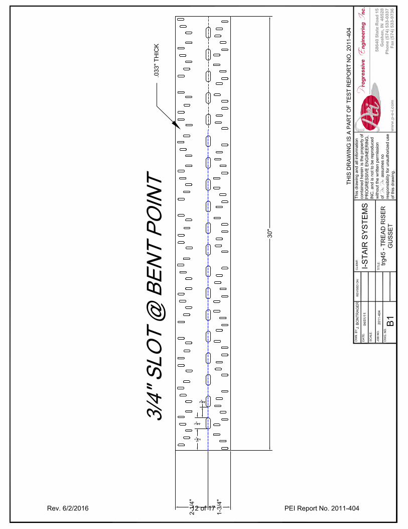
The trg45 consisted of a gang nail plate 30 inches long, with 3/4” slots at the bendpoint. The average measured thickness is .033". The gusset is intended for usewith stair systems 45" wide.
A hydraulic cylinder was positioned above the test specimen, in the desiredlocation, with a load cell, and a 2.000" x 2.000" loading block inline. A lineartransducer was set to measure the deflection of the hydraulic cylinder at the loadpoint, and two other were used to subtract out the system deflection. The systemdeflection was defined as movement not directly related to the loaded parts, suchas the test specimen support at the base and the stringer deflection. The DataAcquisition System was set to record the Load and Deflection throughout thetests. See attached fixture Drawing No. F1765 for details.
The brackets were attached to a 2x4 stringer, which were attached to the baseand back piece which was comprised of 3/4" OSB. The brackets were fastened tothe stringer with 1-1/2" long Galvanized Joist Hanger Nails. The treads and theriser were fastened with 3/4" long Drywall Screws.
The steps were comprised of 3/4” OSB material for the tread as well as the risersupport underneath the tread. Each tread to riser connection was supported withthe trg45. The tread and riser material measured 45 inches wide.
Rev. 6/2/2016 3 of 17 PEI Report No. 2011-404

Date: Project No.: 2011-404Client: I-Stair Systems, Inc. Temp.: 62.7° F
Specimen: i18gs I-Stair Bracket, trg45 Humidity: 39.4% R.H.Test: 2" x 2" Concentrated Load Deflection Limit @ 300 lbf*: .125"
Load (lbf) Step Lip Step BackBetween supports
200 .086 .078 .071300 .103 .100 .107400 .117 .119 .144500 .133 .136 .185600 .149 .155 .232700 .166 .177 .303800 .184 .200 .401
Note: Each location was loaded separately.
* Based on ICC-ES AC174 §4.11 The deflection is measured at the loading nose. The system deflection was removed.
Progressive Engineering Inc.Stair Tread Concentrated Load Test
3/11/2011
Test Location / Deflection1 (in)
Rev. 6/2/2016 4 of 17 PEI Report No. 2011-404

Date: Project No.: 2011-404Client: I-Stair Systems, Inc. Temp.: 62.7° F
Specimen: i20gs I-Stair Bracket, trg45 Humidity: 39.4% R.H.Test: 2" x 2" Concentrated Load Deflection Limit @ 300 lbf*: .125"
Load (lbf) Step Lip Step BackBetween supports
200 .040 .048 .069300 .055 .068 .099400 .068 .089 .130500 .084 .108 .163600 .100 .129 .198700 .120 .149 .235800 .141 .171 .280
Note: Each location was loaded separately.
* Based on ICC-ES AC174 §4.11 The deflection is measured at the loading nose. The system deflection was removed.
Progressive Engineering Inc.Stair Tread Concentrated Load Test
3/11/2011
Test Location / Deflection1 (in)
Rev. 6/2/2016 5 of 17 PEI Report No. 2011-404

Date: Project No.: 2011-404Client: I-Stair Systems, Inc. Temp.: 62.7° F
Specimen: i20gs I-Stair Bracket, trg45 Humidity: 39.4% R.H.Test: 2" x 2" Concentrated Load Deflection Limit @ 300 lbf*: .125"
Load (lbf)Step Lip to
Failure200 .067300 .085400 .103500 .119600 .135700 .151800 .167900 .186
1000 .2051100 .2451200 .3041300 .4361400 .762
Maximum Load: 1,424 lbf
* Based on ICC-ES AC174 §4.11 The deflection is measured at the loading nose. The system deflection was removed.
Progressive Engineering Inc.Stair Tread Concentrated Load Test
3/11/2011
Deflection1 (in)
Failure Mode:
During loading, the bracket directly under theloading nose started to deform at the lowerportion of the bracket. Load was applied until aloss of load, and no subsequent load gainswere noted. See failure pictures for furtherdetails.
Rev. 6/2/2016 6 of 17 PEI Report No. 2011-404

Date: Project No.: 2011-404Client: I-Stair Systems, Inc. Temp.: 62.7° F
Specimen: trg45 1 Humidity: 39.4% R.H.Test: 2" x 2" Concentrated Load Deflection Limit @ 300 lbf*: .125"
Load (lbf)Midspan -
trg45
200 .041300 .059400 .077500 .094600 .111700 .130800 .150
* Based on ICC-ES AC174 §4.11 tread-riser-gusset, 45” 2 The deflection is measured at the loading nose. The system deflection was removed.
Progressive Engineering Inc.Stair Tread Concentrated Load Test
3/11/2011
Deflection2 (in)
Rev. 6/2/2016 7 of 17 PEI Report No. 2011-404

Prog
ress
ive
Eng
inee
ring
Inc.
I-Sta
ir Sy
stem
s2x
2" C
once
ntra
ted
Load
Load
ver
sus
Def
lect
ion
i18G
S I-S
tair
Bra
cket
and
trg4
5
0
100
200
300
400
500
600
700
800
900 0.
000
0.05
00.
100
0.15
00.
200
0.25
00.
300
0.35
00.
400
0.45
0D
efle
ctio
n (in
ches
)
Load (lbf)
Ste
p Li
pB
etw
een
Sup
ports
Ste
p B
ack
Rev. 6/2/2016 8 of 17 PEI Report No. 2011-404

Prog
ress
ive
Eng
inee
ring
Inc.
I-Sta
ir Sy
stem
s2x
2" C
once
ntra
ted
Load
Load
ver
sus
Def
lect
ion
i20G
S I-S
tair
Bra
cket
and
trg4
5
0
100
200
300
400
500
600
700
800
900 0.
000
0.05
00.
100
0.15
00.
200
0.25
00.
300
0.35
00.
400
0.45
0D
efle
ctio
n (in
ches
)
Load (lbf)
Ste
p Li
pB
etw
een
Sup
ports
Ste
p B
ack
Rev. 6/2/2016 9 of 17 PEI Report No. 2011-404

Prog
ress
ive
Eng
inee
ring
Inc.
I-Sta
ir Sy
stem
s2x
2" C
once
ntra
ted
Load
Load
ver
sus
Def
lect
ion
i20G
S I-S
tair
Bra
cket
and
trg4
5
0
200
400
600
800
1,00
0
1,20
0
1,40
0 0.00
00.
050
0.10
00.
150
0.20
00.
250
0.30
00.
350
0.40
00.
450
Def
lect
ion
(inch
es)
Load (lbf)
Ste
p Li
p to
Fai
lure
Rev. 6/2/2016 10 of 17 PEI Report No. 2011-404

Prog
ress
ive
Eng
inee
ring
Inc.
I-Sta
ir Sy
stem
s2x
2" C
once
ntra
ted
Load
Load
ver
sus
Def
lect
ion
trg4
5" I-
Stai
r Bra
cket
0
100
200
300
400
500
600
700
800
900 0.
000
0.05
00.
100
0.15
00.
200
0.25
00.
300
0.35
00.
400
0.45
0D
efle
ctio
n (in
ches
)
Load (lbf)
Mid
span
(trg
45)
Rev. 6/2/2016 11 of 17 PEI Report No. 2011-404
Rev. 6/2/2016 12 of 17 PEI Report No. 2011-404

Rev. 6/2/2016 13 of 17 PEI Report No. 2011-404

Rev. 6/2/2016 14 of 17 PEI Report No. 2011-404

Rev. 6/2/2016 15 of 17 PEI Report No. 2011-404

Rev. 6/2/2016 16 of 17 PEI Report No. 2011-404

Typical test setup Typical test setup
INSERT PICTURE HERE (2.72" H. X 3.63" W.) INSERT PICTURE HERE (2.72" H. X 3.63" W.)
Testing back location Testing midspan back location
Ultimate load failure mode Ultimate load failure mode
Progressive Engineering Inc.
INSERT PICTURE HERE (2.72" H. X 3.63" W.) INSERT PICTURE HERE (2.72" H. X 3.63" W.)
INSERT PICTURE HERE (2.72" H. X 3.63" W.) INSERT PICTURE HERE (2.72" H. X 3.63" W.)
Rev. 6/2/2016 17 of 17 PEI Report No. 2011-404