p e/ advisory circular - critical uncertainties · pdf fileadvisory circular subject: system...
TRANSCRIPT
P e/ U.S. Deportmmr olTronsportotion Federal Aviation Administration -
Advisory Circular
Subject: SYSTEM DESIGN AND ANALYSlS Dntc: G/21/88 ACNo: 25.1309-1A Initiated by: ANN- 110 CJWF
1. PURPOSE. This Advisory Circular (AC) describes various acceptable means for showing compliance with the requirements of fi 25.1309(b), (c), and (d) of the Federal Aviation Regulations (FAR). These means are intended to provide guidance for the experienced engineering and operational Judgment that must form the basis for'compliance findings. They are not mandatory. Other means may be used if they show compliance with this section of the FAR.
2. CANCELLATION. AC 25.1309-l dated g/7/82, is hereby cancelled.
3. APPL!CABILITY. Section 25.13U9(b) provides yeneral requirements for a logical and acceptable inverse relationship between the probability and the severity of each failure condition, and Ej 25.1309(d) requires that compliance be shown primarily by analysis. Section 25.1309(c) provides general requirements for system monitoring, failure warniny, and cap‘aaility for appropriate corrective crew action. Because 0 25.1309(b) and (c) is a regulation of general applicability, it may not be used to replace or alter any allowed design practices or specific requirements of Part 25, and each requirement of 6 2S.l309(b) and (c) applies only if other applicable sections of Part 25 do not provide a specific system requirement that has a similar purpose. While 9 25.13i19(b) and (c) does not apply to the performance, flight characteristics, and structural loads and strength requirements of Subparts B and C, it does apply to any system on which compliance with any of those requirements is based. For example, it does not apply to an airplane's inherent stall characteristics or their evaluation, but it does apply to a stall warning system used to enable compliance with 5 25.207.
4. BACKGROUND. The Part 25 airworthiness standards dre based on the fail-safe design concept that has evolved over the years. A brief description is provided in Paragraph 5. Section 25.1309(b) and (c) sets forth certain objective safety requirements based on this design concept. Many systems, equipment, and their installations have been successfully evaluated to*the applicable requirements of Part 25, including $j 25.1309(b), (c), and (d), without usiny structured means for safety assessments. However, in recent years there has been an increase in the degree of system complexity and integration, and in the number of safety-critical functions performed by systems. Difficulties had been experienced in assessing the hazards that could result from failures of such systems, or adverse interactions amony them. These difficulties led to the use of structured means for showing compliance

AC 25.1309-1A 6/21/88
with Q 25.1309(b). For this and other reasons, yuidance was needed on acceptable means of-compliance with $ 25.1309(b), (c), and (d).
a. Section 25.1309(b) and (d) specifies required safety levels in qualitative terms, and requires that a safety assessment be made. Various assessment techniques have been developed to assist applicants and the FAA in determining that a logical and acceptable inverse relationship exists between the probability and the severity of each failure condition. These techniques include the use of service experience data of similar, previously-approved systems, and thorough qualitative analyses.
b. In addition, difficulties had been experienced in assessing the acceptability of some designs, especially those of systems, or parts of systems, that are complex, that have a high degree of integration, that use new technoloyy or new or different applications of conventional technology, or that perform safety-critical functions. These difficulties led to the selective use of rational analyses to estimate quantitative probabilities, and the development of related criteria based on historical data of accidents and hazardous incidents caused or contributed to by failures. These criteria, expressed as numerical probability ranyes associated with the terms used in Ej 25.1309(b), b ecame commonly-accepted for evaluatiny the quantitative analyses that are often used in such cases to support experienced engineering and operational judgment dnd to supplement qualitative analyses and tests.
5. THE FAA FAIL-SAFE DESIGN CONCEPT. The Part 25 airworthiness standards are based on, dnd incorporate, the obJectives, and principles or techniques, of the fail-safe design concept, which considers the effects of failures and Combinations of failures in defining a safe desiyn.
a. The following basic objectives pertaining to failures apply:
(1) In any system or subsystem, the failure of any sinyle element, component, or connection duriny any one flight (brake release through ground deceleration to stop) should be assumed, reyardless of its probability. Such
.sinyle failures should not prevent continued safe flight and landing, or significantly reduce the capability of the airplane or the ability of the crew to cope with the resulting failure conditions.
(2) Subsequent failures during the same flight, whether detected or latent, and combinations thereof, should also be assumed, unless their joint probability with the first failure is shown to be extremely improbable.
Par 4

6/21/88 AC 25.1309-1A
b. The fail-safe design concept uses the following design principles or techniques in order to ensure a safe design. The use of only one of these principles or techniques is seldom adequate. A combination of two or more is usually needed to provide a fail-safe design; i.e., to ensure that major failure conditions are improbable and that catastrophic tailure conditions are extremely improbable.'
(1) Desiyned Inteyrity and Quality, including Life Limits, to ensure intended function and prevent failures.
(2) Redundancy or Backup Systems to enable continued function after any single (or other defined number of) failure(s); e.g., two or more engines, hydraulic systems, flight control systems, etc.
(3) Isolation of Systems, Components, and Elements so that the failure of one does not cause the failure of another. Isolation is also termed independence.
(4) Proven Reliability so that multiple, independent failures are unlikely to occur during the same flight.
(5) Failure Warning or Indication to provide detection.
(6) Flightcrew Procedures for use after failure detect ion, to enable continued safe flight and landing by specifying crew corrective action.
(7) Checkability: the capability to check a component 's condition.
(8) Designed Failure Effect Limits, including the capability to sustain damage, to limit the safety impact or effects of a failure.
(9) Designed Fdilure Path to control and direct the effects of a failure in a way that limits its safety impact.
(10) haryins or Factors of Safety to allow for any undefined or unforeseeable adverse conditions.
(11) Error-Tolerance that considers adverse effects of foreseeable errors during the airplane's design, test, manufacture, operation, and maintenance.
6. DEFINITI3NS. The following definitions apply to the system design and analysis requirements of 0 25,1309(b), (c), and (d) and the guidance material provided in this AC. They should not be assumed to apply to the same or
Par 5
.AC 25.1309-1A 6/21/88
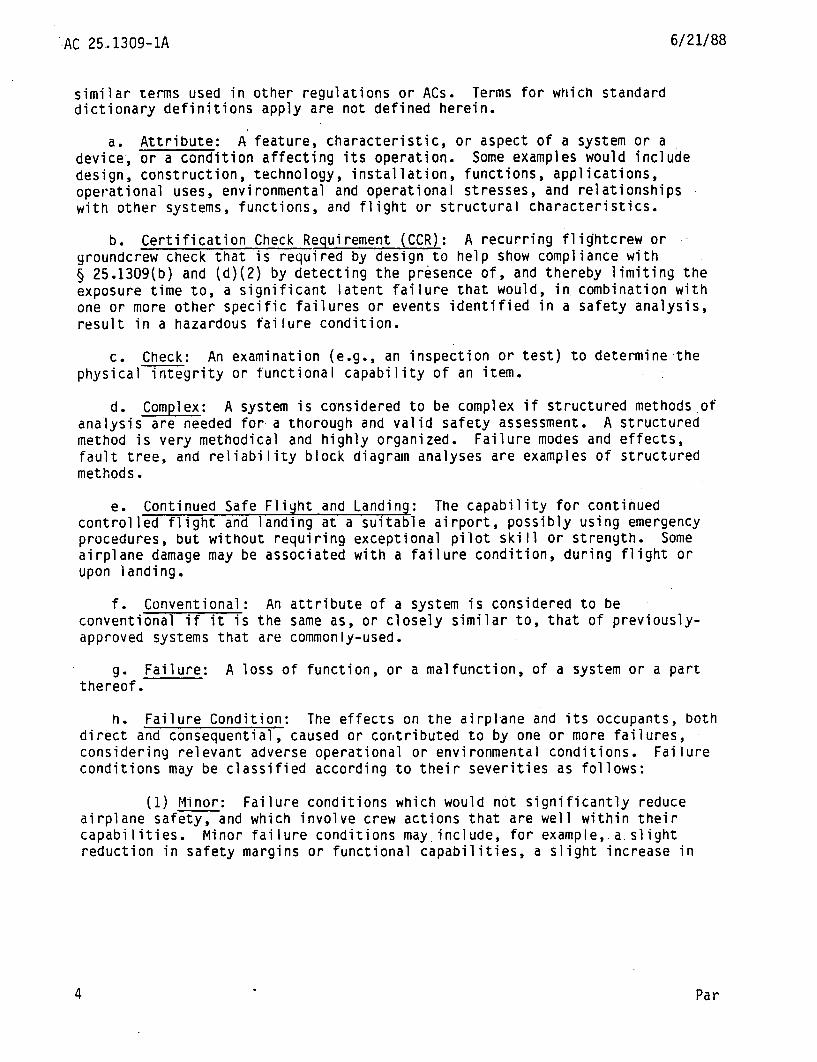
similar terms used in other regulations or ACs. Terms for which standard dictionary definitions apply are not defined herein.
a. Attribute: A feature, characteristic, or aspect of a system or a device, or a condition affecting its operation. Some examples would include design, construction, technology, installation, functions, applications, operational uses, environmental and operational stresses, and relationships with other systems, functions, and flight or structural characteristics.
b. Certification Check Requirement (CCR): A recurring flightcrew or groundcrew check that is required by design to help show compliance with 0 25.1309(b) and (d)(2) by detecting the presence of, and thereby limiting the exposure time to, a significant latent failure that would, in combination with one or more other specific failures or events identified in a safety analysis, result in a hazardous failure condition.
c. Check: An examination (e.g., an inspection or test) to determine.the physicalintegrity or functional capability of an item.
d. Complex: A system is considered to be complex if structured methods,of ana‘lysis are needed for a thorough and valid safety assessment. A structured method is very methodical and highly organized. Failure modes and effects, fault tree, and reliability block diagram analyses are examples of structured methods.
e. Continued Safe Flight and Landing: The capability for continued controlled flight and landing at a suitable airport, possibly using emergency procedures, but without requiring exceptional pilot skill or strength. Some airplane damage may be associated with a failure condition, during flight or upon landing.
f. Conventional: An attribute of a system is considered to be conventional if it is the same as, or closely similar to, that of previously- approved systems that are commonly-used.
9* Failure: A loss of function, or a malfunction, of a system or a part thereof.
h. Failure Condition: The effects on the airpl-ane and its occupants, both direct and consequential, caused or contributed to by one or more failures, considering relevant adverse operational or environmental conditions. Failure conditions may be classified according to their severities as follows:
(1) Minor: Failure conditions which would not significantly reduce airplane safety, and which involve crew actions that are well within their capabilities. Minor failure conditions may.include, for examp'le,.a.slight reduction in safety margins or functional capabilities, a slight increase in
Par

6/21/88 AC 25.1303-1A
crew workload, such as routine fliyht plan changes, or some inconvenience to occupants.
(2) Major: Failure conditions which would reduce the capability of the airplane or the ability of the crew to cope with adverse operating conditions to the extent that there would be, for example, --
(i) A significant reduction in safety margins or functional capabilities, a siynificant increase in crew workload or in conditions impairing crew efficiency, or some discomfort to occupants; or
(ii) In more severe cases, a large reduction in safety margins or functional capabilities, higher workload or physical distress such that the crew could not be relied on to perform its tasks accurately or completely, or adverse effects on occupants.
(3) Catastrophic: Failure conditions which would prevent continued safe flight and landing.
i. Redundancy: The presence of more than one independent means for accomplishing a given function or flight operation. Each means need not necessarily be identical.
L Qualitative: Those analytical processes that assess system and airplane safety in a subjective, nonnumerical manner.
k. Quantitative: Those analytical processes that apply mathematical methods to assess system and airplane safety.
7. IILSCUSSION. Section 25.1309(b) and (d) requires substantiation by analysis, and where necessary, by, appropriate ground, flight, or simulator tests, that a logical and acceptable inverse relationship exists between the probability and the severity of each failure condition. However, tests are not required to verify failure conditions that are postulated to be catastrophic. As discussed in Paragraph 3, some systems and some functions must be evaluated for compliance with certain specific system requirements that take precedence over certain requirements of 5 25.1309(b) and (c) that have similar purposes. In either case, however, the goal is to ensure an acceptable overall airplane safety level, considering all failure conditions of all systems.
a. The requirements of 6 25.1309(b) and (d) are intended to ensure an orderly and thorough evaluation of the effects on safety of foreseeable failures or other events, such as errors or external circumstances, separately or in combination, involving one or more system functions. The interactions of these factors within a system and among relevant systems should be considered.
Par 6

AC 25.1309-1A 6/21/88
b. The severities of failure conditions may be evaluated according to the following considerations:
(1) Effects-on the airplane, such as reductions in safety margins, degradations in performance, loss of capability to conduct certain flight operations, or potential or consequential effects on structural integrity.
(2) Effects on the crewmembers, such as increases above,their normal workload that would affect their ability to cope with adverse operational or environmental conditions or subsequent failures.
(3) Effects on the occupants; i.e., passenyers and crewmembers.
c. For convenience in conducting design assessments, failure conditions may be classified according to their severities as minor, major, or catastrophic. Paragraph 6h provides accepted definitions of these terms.
(1) The classification of failure conditions does not depend on whether or not a system or function is required by any specific regulation. Some systems required by specific regulations, such as transponders, position lights, and public address systems, may have the potential for only minor
Conversely, other systems not required by any specific flight management systems and automatic landing systems,
ial for major or catastrophic failure condi'tions.
failure conditions. regulation, such as may have the potent
(2) Regard less of the types of assessment used, the classification of failure conditions should always be accomplished with consideration of all relevant factors; e.g., system, crew, performance, operational, external, etc. Examples of factors would include the nature of the failure modes, any effects or limitations on performance, and any required or likely crew action. It is particularly important to consider factors that would alleviate or intensify the severity of a failure condition. An example of an alleviating factor would be the continued performance of identical or operationally-similar functions by other systems not affected by a failure condition. Examples of intensifying factors would include unrelated conditions that would reduce the ability of the crew to cope with a failure condition, such as weather or other adverse operational or environmental conditions, or failures of other unrelated systems or functions.
d. The probability that a failure condition would occur may be assessed as probable, improbable, or extremely improbable. These terms are explained in Paragraphs 9e and 1Ub. Each failure condition should have a probability
6 Par 7

c/21/88 AC 25.1309-1A
that is inversely-related to its severity. Figure 1, Probability vs. Consequence Graph, illustrates this relationship.
(1) Minor failure conditions may be probable.
(2) Major failure conditions must be improbable.
(3) Catastrophic failure conditions must be extremely improbable.
Figure 1: Probability vs. Consequence Graph
Catastrophic Accident
AdVeRGe Effects on occupants
Airpbne Damage
Emergency Procedures
Procedures
Probability of Failwe Condition
e. An assessment to identify and classify failure conditions is necessarily qualitative. On the other hand, an assessment of the probability of a failure condition may be either qualitative or quantitative. An analysis may range from a simple report that interprets test results or compares two similar systems to a detailed analysis that may (or may not) include estimated numerical probabilities. The depth and scope of an analysis depends on the types of functions performed by the system, the severities of system failure conditions, and whether or not the system is complex. Regardless of its type, an analysis should show that the system and its installation can tolerate failures to the extent that major failure conditions, are improbable and catastrophic failure conditions are extremely improbable.
(1) Experienced engineering and operational judgment should be applied when determining whether or not a system is complex. Comparison with similar, previously-approved systems is sometimes helpful. All relevant system
Par 7

AC 25.1309-1A 6/21/88
attributes should be considered; however, the complexity of the software used to program a digital computer-based system should not be considered because the software is assessed and controlled by other means, as described in Paragraph 7i. -
(2) An analysis should always consider the application of the fail- safe design concept described in Paragraph 5, and give special attention to ensuring the etfective use of design techniques that would prevent single failures or other events from damaying or otherwise adversely affecting more than one redundant system channel or more than one system performing operationally-similar functions. When considering such common-cause failures or other events, consequential or cascading effects should be taken into account if they would be inevitable or reasonably likely.
(3) Some examples of such potential common-cause failures or other events would include rapid release of energy from concentrated sources such as uncontained failures of rotating parts' or pressure vessels, pressure differentials, noncatastrophic structural failures, loss of environmental conditioning, disconnection of more than one subsystem or component by overtemperature protection devices, contamination by fluids, damage from localized fires, loss of power, excessive voltage, physical or environmental interactions among parts, use of incorrect, faulty, or boyus parts, human or machine errors, and foreseeable adverse operational conditions, environmental conditions, or events external to the system or to the airplane.
f. As discussed in Paragraphs 8c(l) and 8d(2), compliance for a system or part thereof that is not complex may sometimes be shown by design and installation appraisals and evidence of satisfactory service experience on other airplanes using the same or other systems that are similar in their relevant attributes.
Y- In general, a failure condition resulting from a single failure mode of a device cannot be accepted as being extremely improbable. In very unusual cases, however, experienced engineering judgment may enable an assessment that such a failure mode is not a practical possibility. When making such an assessment, all possible and relevant considerations should be taken into account, including all relevant attributes of the device. Service experience showiny that the failure mode has not yet occurred may be extensive, but it can never be enough. Furthermore, flightcrew or groundcrew checks have no value if a catastrophic failure mode would occur suddenly and without any prior indication or warning. The assessment’s logic and rationale should be so straightforward and readily-obvious that, viewpoint,
from a realistic and practical any knowledgeable, experienced person would unequivocally conclude
that the failure mode simply would not occur, unless it is associated with a wholly-unrelated failure condition that would itself be catastrophic.
8 Par 7

6/21/88 AC 25.1309-1A
h. Section 25.1309(c) provides requirements for system monitoring, failure warning, and capability for appropriate corrective crew action. Guidance on acceptable means of compliance is provided in Paragraph 89.
i. In general, the means of compliance described in this AC are not directly applicable to software assessments because it is not feasible to assess the number or kinds of software errors, if any, that may remain after the completion of system design, development, and test. Advisory Circular ZO-115A dated August 12, 1986, "Radio Technical Commission for Aeronautics Document RTCAIDO-17BA," or later revisions thereto, provides acceptable means for assessinq and controlling the software used to program digital computer-based systems. Uocument RTCA/DO-178A dated March 22, 1985, "Software Considerations in Airborne Systems and Equipment Certification," defines and uses certain terms to classify the criticalities of functions. For information, these terms have the following relationships to the terms used in this AC to classify failure conditions: failure conditions adversely affecting non-essential functions would be minor, failure conditions adversely affecting essential functions would be major, and failure conditions adversely affecting critical functions would be catastrophic.
8. ACCEPTABLE TECHNIQUES. The applicant is responsible for applying reasonable criteria and experienced engineering and operational judgment to identify and classify each failure condition and to choose the methods of assessment to be used to determine compliance with 0 25.1309(b), (c), and (d). All relevant applicant engineering organizations, such as systems, structures, propulsion, and flight test, should be involved in the identification and classification of failure conditions. The applicant should then obtain early concurrence of the cognizant certificating office on the failure conditions, their classifications, and the choice of an acceptable means of compliance. This paragraph describes acceptable techniques, but not the only techniques, for determining compliance. (Paragraph 12 briefly and partially summarizes these techniques.) Regardless of the techniques used, the considerations described in Paragraphs 7c and 7e should always be taken into account.
a. Functional Hazard Assessment. A useful preliminary step is to conduct a functional hazard assessment (FHA)to identify and classify potentially- hazardous failure conditions, and to describe them in functional and operational terms. An FHA is qualitative and is conducted usiny experienced engineering and operational judgment. The criteria described in Paragraph 7f are sometimes sufficient for systems as described therein. For other systems, an FHA tends to be structured because it involves a comprehensive, systematic, deductive, high-level examination of system functional failures to identify and classify the resulting failure conditions. An FHA is often used by applicants as a preliminary engineering tool to help determine the acceptability of a design concept, to identify potential problem areas or desirable design changes, or to determine the need for and scope of any additional analyses. At the applicant's option, an FHA may be included in the certification documentation. In some cases, it may show that additional documentation is not needed.
Par 7 9

AC 25.1309-1A 6121188
b. Analysis of Minor Failure Conditions. An analysis, which could be an FHA, should consider the effects of system failures on other systems or their functions. It is complete if it shows that system failures would cause only minor failure conditions. If the system, in itself, has the potential for only minor failure conditions, and the common design practice of providing physical and functional isolation between it and other systems is used, an analysis that shows such isolation is usually sufficient.
C. Analysis of Major Failure Conditions. Major failure conditions must be shown to be improbable. Those that are more severe (reference Paragraph 6h(2)(ii)) should have smaller probabilities than those that are less severe (reference Paragraph 6h(2)(i)). The considerations described in Paragraphs 7c and 7e should always be taken into account.
(1) Using experienced engineering and operational Judgment, an assessment as described in Paragraph 7f is often sufficient. Compliance may also be shown qualitatively by a failure modes and effects analysis, or by a fault tree or reliability block diagram analysis. A quantitative analysis is sometimes used to support experienced judgment and to supplement qualitative analysis for the more severe major failure conditions.
(2) An analysis of a redundant system is usually complete if it shows isolation between redundant system channels and satisfactory reliability for each channel. For complex systems, a failure modes and effects analysis or a fault tree or reliability block diagram analysis is often used to show that isolation actually exists (i.e., that any single failure would not affect more than one redundant system channel), and to show that the failure modes of the system do not have any adverse effects on safety-related functions performed by other systems.
d. Analysis of Catastrophic Failure Conditions. Catastrophic failure conditions must be shown to be extremely improbable. A very thorough safety assessment is necessary. The considerations described in Paragraphs lc and-7e should always be taken into account.
(1) The assessment usually consists of an appropriate combination of qualitative and quantitative analyses, such as those described in Paragraphs 9 and 1U.
(2) Using experienced engineering and operational judgment, an assessment as described in Paragraph 7f is sometimes sufficient, provided that the service experience data, which should be based on commonly-used systems that are identical or have a very close similarity in their relevant
10 Par 8

6/21/88 AC 25.1309-1A
attributes, show that no potentially-catastrophic defects have been discovered in the identical or similar~systems or their installations.
e. Operational or Environmental Conditions. A probability of one should usually be used for encountering a discrete condition for which the airplane is desiyned, such as instrument meteorological conditions or Category III weather operations. On the other hand, reasonable and rational consideration of the statistically-derived probability of a random condition may usually be included in an analysis, provided it is based on an applicable supporting data base and its statistical distribution. When combining the probability of such a random condition with that of a system failure, care should be taken to ensure that the condition and the system failure are independent of one another, or that any dependencies are properly accounted for. Two examples of the reasonable and rational use of such random conditions are the encountering of hazardous turbulence or gust levels after the failure of a structural load alleviation system, and the availability of a suitable alternate airport having a crosswind lower than that at the intended destination airport after a system failure that results in a loss of high rudder authority. The applicant should obtain early concurrence of the cognizant certificating office when such conditions are to be included in an analysis.
f. Latent Failures. A latent failure is one which is inherently undetected when it occurs. A sionificant latent failure is one which would, in combination with one or more other specific failures or events, result in a* hazardous failure condition. Because the frequency at which a device is checked directly affects the probability that any latent failure of that device exists, CCRs (reference Paragraph 6b) may be used to help show compliance with 5 25.1309(b) and (d)(2) for significant latent failures. However, the use of CCRs or other checks in lieu of practical and reliable failure monitoring and warning systems to detect siynificant latent failures when they occur does not comply with 5 25.1309(c) and (d)(4). A practical failure monitoring and warniny system is one which is considered to be within the state-of-the-art. A reliable failure monitoring and warning system is one which would not result in either excessive failures of a yenuine warning, or excessive or untimely false warnings which can sometimes be more hazardous than lack of provision for, or failures of, yenuine but infrequent warninys. Experienced judgment should be applied when determining whether or not a failure monitoring and warning system would be practical and reliable. Comparison with similar, previously-approved systems is sometimes helpful. Paragraphs Bg(4) and 11 provide further guidance on the use of CCRs.
9* Acceptable means of compliance with 6 25.1309(c). Section 25.1309(c) requires that warning information must be provided to alert the crew to unsafe system operating conditions, and to enable them to take appropriate corrective action. It also requires that systems, controls, and associated monitoring
Par 8 11

AC 25.1309-1A 6/21/88
and warning means must be designed to minimize crew errors which COlJld create additional hazards. Compliance with this section is shown qualitatively.
(1) Failure warning or indication may either be natural (inherent) or designed into a system. In either case, it should be timely, rousing, obvious, clear, and unambiguous. It should occur at a point in a potentially- catastrophic sequence of failures where the airplane's capability and the crew's ability still remain sufficient for appropriate corrective crew action.
(2) Unless they are accepted as normal airmanship, procedures for the crew to follow after the occurrence of failure warning should be described in the FAA-approved Airplane Flight Manual (AFM) or AFM revision or supplement.
(3) Even.if operation or performance is unaffected or insignificantly affected at the time of failure, warning is required if it is considered necessary for the crew to take any action or observe any precautions. Some examples would ‘include reconfiguring a system, being aware of a reduction in safety margins, changing the fliyht plan or regime, or makiny an unscheduled landing to reduce exposure to a more hazardous failure condition that would result from subsequent failures or operational or environmental conditions. Warning is also required if a failure must be corrected before a subsequent flight. If operation or performance is unaffected or insignificantly affected, warning may be inhibited during specific phases of flight where corrective action by the crew is considered more hazardous than no action. :
(4) The use of CCRs or other checks in lieu of practical and reliable failure monitoring and warning systems to detect siynificant latent failures when they occur does not comply with 0 25.1309(c) and (d)(4). Paragraphs 8f and 11 provide further guidance on the use of CCRs.
(5) The assumptions of Paragraph lla that the flightcrew will take appropridte corrective action dnd perform required checks correctly are based on compliance with the requirement for a design that minimizes the potential for hazardous crew errors; however, quantitative assessments of tne probabilities of cr,ew errors are not considered feasible. Particular attention should be given to the placement of switches or other control devices, relative to one another, so as to minimize the potential for inadvertent incorrect crew action, especially during emeryencies or periods of high workload. Extra protection, such as the use of guarded switches, may sometimes be needed.
12
9. QUALITATIVE ASSESSMENT. Various methods for assessing the causes, severities, and likelihood of potential failure conditions are available to support experienced engineering and operational judgment. Some of these methods are structured. The various types of analysis are based on either
Par 8

6/21/88 AC 25.1309-1A
inductive or deductive approaches. Descriptions of typical types of analysis and explanations of qualitative probability terms are provided below.
a. Design Appraisal. A qualitative appraisal of the integrity and safety of the design. An effective appraisal requires experienced judgment, and in accordance with Paragraph 7e, should place special emphasis on any failure conditions that are likely to prevent continued safe flight and landing.
b. Installation Appraisal. A qualitative appraisal of the integrity and safety of the installation. An effective appraisal requires experienced judgment, and in accordance with Paragraph 7e, should place special emphasis on any failure conditions that are likely to prevent continued safe flight and landing. Any deviations from normal, industry-accepted installation practices, such as clearances or tolerances, should be evaluated, especially when appraising modifications made after entry into service.
c. Failure Modes and Effects Analysis. A structured, inductive, bottom-up analysis which is used to evaluate the effects on the system and the airplane of each possible element or component failure. When properly formatted, it will aid in identifying latent failures, and the possible causes of each failure mode.
d. Fault Tree or Reliability Block Diagram Analysis. Structured, deductive, top-down analyses which are used to identify the conditions, failures, and events that would cause each defined failure condition. They are graphical methods of identifying the logical relationship between each particular failure condition and the primary element or component failures, other events, or combinations thereof that can cause it. A failure modes and effects analysis is usually used as the source document for those primary failures or other events. A fault tree analysis is failure-oriented, and is conducted from the perspective of which failures must occur to cause a defined failure condition. A reliability block diagram analysis is success-oriented, and.is conducted from the perspective of which failures must not occur to preclude a defined failure condition.
e. Qualitative Probability Terms. When using qualitative analyses to determine compliance with $ 25.1309(b), the following descriptions of the probability terms used in this regulation and this AC have become commonly- accepted as aids to engineering judgment:
(1) Probable failure conditions are those anticipated to occur one or more times during the entire operational life of each airplane.
(2) Improbable failure conditions are those not anticipated to occur during the entire operational life of a single random airplane. However, they may occur occasionally during the entire operational life of all airplanes of one type.
Par 9 13

AC 25.1309-1A 6121188
(3) Extremely Improbable tailure conditions are those so unlikely that they are not anticipated to occur during the entire operational life of all airplanes of one type.
10. QUANTITATIVE ASSESSMENT. A quantitative analysis may be used to support experienced engineering and operational judgment and to supplement qualitative analyses. A description of such an analysis, discussion and guidance information, and explanations of quantitative probability terms are provided below. A quantitative analysis is often used for catastrophic or severe major failure conditions of systems that are complex, that have insufficient service experience to help substantiate their safety, or that have attributes that differ significantly from those of conventional systems.
a. Probability Analysis. A failure modes and effects, fault tree, or reliability block diagram analysis which also includes numerical probability i nformdti on. The probabilities of primary failures cdn be determined from failure rate data and exposure times, using failure rates derived from service experience on identical or similar items, or acceptable industry standards. The conventional mathematics of probability can then be used to calculate the estimated probdbility of each tailure condition as a function of the estimated probabilities of its identified contributory failures or other events.
(1) It is recognized that, for various reasons, component failure rate data are not precise enough to enable accurate estimates of the probabilities of failure conditions. This results in some degree of uncertainty, as indicated by the wide line on Figure 1, Probability'vs. Consequence Graph, and the expression "on the order of" in the descriptions of the quantitative probability terms that are provided in Paragraph lob. When calculating the estimated probability of each failure condition, this uncertainty should be accounted for in a way that does not compromise safety.
(2) Because the improbable range is broad (reference Paragraph 8c), the applicant should obtain early concurrence of the cognizant certificating office on an acceptable probability tor each major failure condition. Unless acceptable probability criteria are provided elsewhere, such as in other ACs, acceptable probabilities for failure conditions should be derived from complete event scenarios leading to an inability for continued safe flight and landing. The considerations described in Paragraphs 7c dnd 7e should always be taken into account so that the probability requirements are rational and realistically-based. Using experienced engineering and operational judgment, acceptable probabilities should have reasonable tolerances because the uncertainty is accounted for as discussed in Paragraph lOa(1).
b. Quantitative Probability Terms. When using quantitative analyses to help determine compliance with 5 25.1309(b), the following descriptions of the probability terms used in this regulation and this AC have become commonly- accepted as aids to engineering judgment. They are usually expressed in terms
14 Par 9

6/2i/aa AC 25.1309-1A
of acceptable numerical probability ranges for each flight-hour, based on a flight of mean duration for the airplane type. However, for a function which is used only during a specific flight operation; e.g., takeoff, landing, etc.,
'the acceptable probability should be based on, and expressed in terms of, .the flight operation's actual duration.
(1) Probable failure condl$ions are those having a probability yreater than on the order of 1 X 10 .
(2) Improb$ble failure the order of 1 X 10
conditions are those having a probabil,Jty on or less, but greater than on the order of 1 X 10 .
(3) Extremely Improbable-4ailure conditions are those having a probability on the order of 1 X 10 or less.
11. OPERATIONAL AN0 MAINTENANCE CUNSIUEKATIONS. This AC addresses only those operational and maintenance considerations that are directly related to compliance with 5 25.1309(b), (c), and (d); other operational and maintenance considerations are not discussed herein. Flightcrew and groundcrew tasks related to compliance with this regulation should be appropriate and reasonable. However, as discussed in Paragraph 8g(5), quantitative assessments of the probabilities of crew errors are not considered teasible. Therefore, reasonable tasks are those for which full credit can be taken because the flightcrew or groundcrew can realistically be anticipated to perform them correctly and when they are required or scheduled. In addition, based on experienced engineering and operational judgment, the discovery of obvious failures during normal operation and maintenance of the airplane may be considered, even though such failures are not the primary purpose or focus of the operational or maintenance actions.
a. Flightcrew Action. When assessing the ability of the flightcrew to cope with a failure condition, the warning information and the complexity of the required action should be considered (reference Paragraph 8g(5)). If the evaluation indicates that a potential failure condition can be alleviated or overcome during the time available without jeopardizing other safety-related flightcrew tasks and without requiring exceptional pilot skill or strength, credit may be taken for correct and appropriate corrective action, for both qualitative and quantitative assessments. Similarly, credit may be taken for correct flightcrew performance of CCKs if overall flightcrew workload during the time available to perform them is not excessive and if they do not require exceptional pilot skill or strength. Unless flightcrew actions are accepted as normal airmanship, they should be described in the FAA-approved AFM or AFM revision or supplement.
b. Groundcrew Action. Credit may be taken for correct groundcrew accomplishment of reasonable CCRs, for both qualitative and quantitative assessments. Such requirements should be provided for use in FAA-approved maintenance programs.
Par 10 15

AC 25.1309-1A 6/21/88
C. Certification Check Requirements. As discussed in Paragraphs 6b and 8f, CCRs (also referred to as Certification Maintenance Requirements, or CMRs).may be needed to help show compliance with 5 25.1309(b) and (d)(Z) for significant latent failures. Rational methods, tihich usually involve quantitative analyses or relevant service experience data, should be used to determine CCR intervals. These intervals should have reasonable tolerances so that CCRs can be performed concurrently with other maintenance, inspection, or check procedures not required by design for compliance with 9 25.1309(b) and (d)(Z). Such tolerances are dCCeptdble because the uncertainty described in Paragraph lOa(1) is accounted for as discussed therein. If CCRs are used, they and their intervals and tolerances, and any post-certification changes, or procedures provided in the type design for an airplane owner or operator to make such changes, should be approved by, or with the concurrence of, the certificating office having cognizance over the type design that relates to the system and its installation.
(1) Any applicant originatiny CCRs that dre to be performed by flightcrews should provide all relevant information to owners and operators of the airplane in the FAA-approved AFM or AFM revision or supplement.
(2) Any applicant originating CCRs that are to be performed by groundcrews should provide all relevant information to owners and operators of the airplane early enough for well-planned, timely incorporation into FAA- approved maintenance programs. If appropriate, approved procedures for reasonable adjustments to CCR intervals as a result of knowledge acquired from service experience may be provided for use in FAA-approved maintenance programs.
(3) Any owner or operator of an airplane may request that alternative CCRs or their intervals be allowed and specified in an operator's specification approved under the applicable operating regulation or in accordance with an FAA-approved maintenance program. As discussed in Paragraph llc, concurrence of the certificating office having cognizance over the type design that relates to the system and its installation is necessary.
d. Flight with Equipment or Functions Inoperative. Any applicant may elect to develop a list of equipment and functions which need not be operative for safe flight and landiny, based on stated compensating precautions that should be taken; e.g., operational or time limitations, or flightcrew or groundcrew checks. The documents used to show compliance with 5 25.1309(b), (c), and (d), together with any other relevant information, should be considered in the development of this list, which then becomes the basis for a Master Minimum Equipment List (MMEL). Experienced engineering and operational Judyment should be applied during the development of the MMEL.
16 Par 11

6/21/88 AC 25.1309-1A
12. STEP-BY-STEP GUIDE. This guide and Fi.ure 2, Depth of Analysis Flowchart, are provided primarily for the use of app +- icants who are not familiar with the various methods and procedures yenerally‘used by industry to conduct design safety assessments.
I Conduct functional I Fiaure
I hazard assessment. (Reference Paragraph 8a)
I Depth of Analysis Flowchafl
Show that the failure
l conditions are minor. (Reference Paragraph 8b)
complex? (Reference
those used in other airplanes in its relevant attributes?
Justifysimilarity. : (Reference Paragraphs 71, and 8c(l) or 8d(2))
Failure condition classification:
I Mapr
m--2..- -__-lt.--L.- ---------_ ~onuucr qualnarrve assessments. (Reference Paragraphs EC or Ed, and 9)
in its relevant attributes?
I Conduct qualitative assessments, andquantitative assessmentsas appropriate. (Reference
Severe Major, or Catastrophic Paragraphs EC or Ed, 9, and 10)
This guide and Figure 2 are not certification checklists, and they do not include all the information provided in this AC. There is no necessity for,an app'licant to use them or for the FAA to accept them, in whole or in part, to
Par 12 17

AC X.1309-1A 6121188
show compliance with any regulation. Their sole purposes are to assist applicants by illustrating a systematic approach to design safety assessments, to enhance understandiny and communication by summariziny some of the information provided in this AC, and to provide some suggestions on documentation.
a. Define the system and its interfaces, and identify the functions that the system is to perform. Determine whether or not the system is complex, similar to systems used on other airplanes, and conventional.
b. Identify and classify the significant (i.e., non-trivial) failure conditions. All relevant applicant engineeriny organizations, such as systems, structures, propulsion, and flight test, should be involved in this process. This identification and classification may be done by conductiny an FHA, which is usually based on one of the following methods, as appropriate:
(1) If the system is not complex, and if its relevant attributes are similar to those of systems used on other airplanes, this identification and classification may be derived from design and installation appraisals and the service experience of the comparable, previously-approved systems.
(2) If the system is complex, it is necessary to systematically postulate the effects on the safety of the airplane and its occupants- resultiny from any possible failures, considered both individually and in combination with other failures or events.
Choose the means to be used to determine compliance with 5 25.:309(b), (c), and (d). The depth and scope of the analysis depends on the types of functions performed by the system, the severities of system failure conditions, and whether or not the system is complex. For major failure conditions, experienced engineering and operational judgment, desiyn and installation appraisals, and comparative service experience data on similar systems may be acceptable, either on their own or in conjunction with qualitative analyses or selectively-used quantitative analyses. For catastrophic failure conditions, a very thorough safety assessment is necessary. The applicant should obtain early concurrence of the cognizant certificatiny office on the failure 'conditions, their classifications, and the choice of an acceptable means of compliance.
d. Implement the design and produce the data which are dgreed with the certificating office as being acceptable to show compliance. To the extent feasible, an analysis should be self-contained; however, if it is not, all other documents needed should be referenced. A typical analysis should include the followiny information to the extent necessary to show compliance:
(1) A statement of the functions, boundaries, and interfaces of the system.
18 Par 12

:5/21/88 AC 25.1309-1A
(2) A list of the component parts and equipment of which the system is comprised, and their design standards. This list may reference other documents; e.g.-, Technical Standard Orders (TSOs), manufacturer's or military
.specifications, etc.
(3) The conclusions, including a statement of the failure conditions and their classifications and probabilities (expressed qualitatively or quantitatively, as appropriate), that show compliance with the requirements of 0 25.1309(b), (c), and (d).
(4) A description that establishes correctness and completeness and traces the work leading to the conclusions. This description should include the basis for the classification of each failure condition (e.g., analysis or ground, flight, or simulator tests.) It should also include a description of precautions taken against common-mode or common-cause failures, provide any data such as component failure rates and their sources and applicability, support any assumptions made, and identify any required flightcrew or groundcrew actions, including any CCRs.
(6 LEROY A. KEITH 1 Manager, Aircraft Certification Division
Par 12 19