p-51d mustang bnf instruction manual - bind-n-fly
TRANSCRIPT
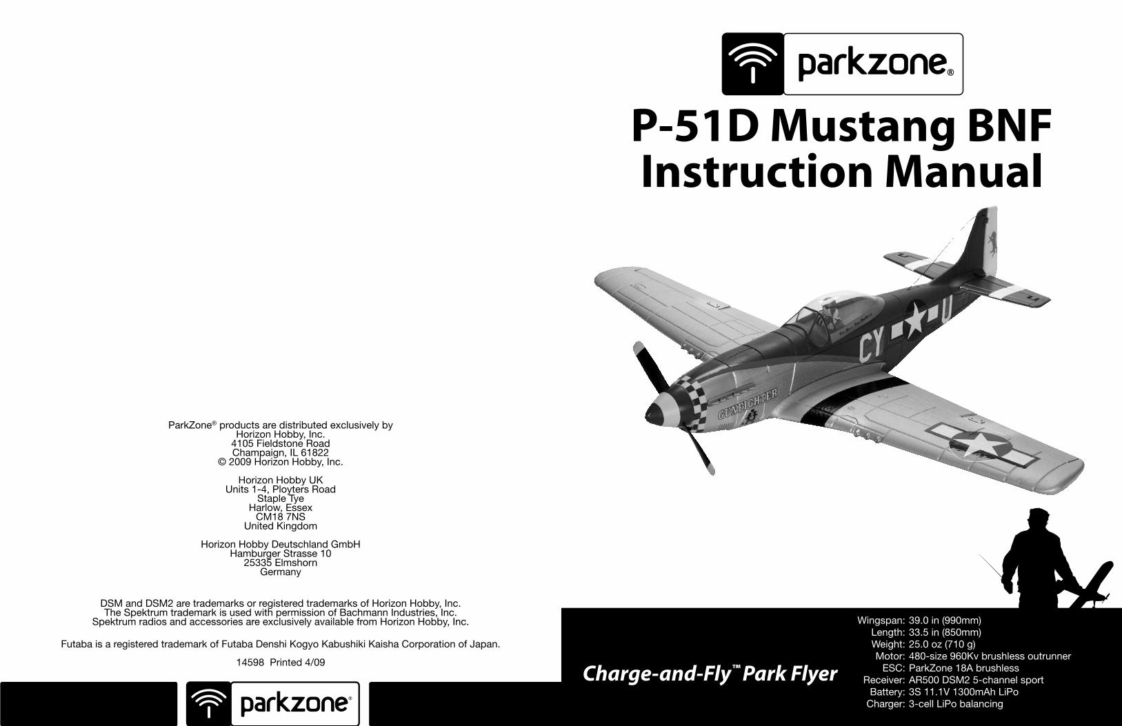
Charge-and-Fly™ Park Flyer
P-51D Mustang BNFInstruction Manual
ParkZone® products are distributed exclusively by Horizon Hobby, Inc.
4105 Fieldstone Road Champaign, IL 61822
© 2009 Horizon Hobby, Inc.
Horizon Hobby UKUnits 1-4, Ployters Road
Staple Tye Harlow, Essex
CM18 7NSUnited Kingdom
Horizon Hobby Deutschland GmbHHamburger Strasse 10
25335 Elmshorn Germany
DSM and DSM2 are trademarks or registered trademarks of Horizon Hobby, Inc. The Spektrum trademark is used with permission of Bachmann Industries, Inc.
Spektrum radios and accessories are exclusively available from Horizon Hobby, Inc.
Futaba is a registered trademark of Futaba Denshi Kogyo Kabushiki Kaisha Corporation of Japan.
14598 Printed 4/09
Wingspan: 39.0 in (990mm) Length: 33.5 in (850mm) Weight: 25.0 oz (710 g) Motor: 480-size 960Kv brushless outrunner ESC: ParkZone 18A brushless Receiver: AR500 DSM2 5-channel sport Battery: 3S 11.1V 1300mAh LiPo Charger: 3-cell LiPo balancing
3 4
Congratulations on your purchase of the ParkZone® P-51D Mustang. The North American P-51D Mustang is arguably the most famous military aircraft of all time. Many will credit the fall of the Nazi regime in Europe to the development and production of this great fighter. This was not only because it was able to protect long-range bombers such as the B-17, but because of outstanding offensive capabilities.
Your ParkZone P-51D Mustang BNF purchase includes everything needed to get you in the air—all in one box. You will only need to attach the wing, horizontal tail, charge the battery pack, and bind to your favorite Spektrum™ DSM2™ transmitter prior to taking to the air. Everyone at ParkZone is committed to giving you the most enjoyable flight experience possible. In order for your first flight to be safe and successful, we ask that you do not fly until you have read these instructions thoroughly.
Charging the Aircraft BatteryThe charger included with your P-51D Mustang uses unique circuitry that ensures an accurate charge every time and protects your Lithium Polymer battery from the dangers of overcharging. This charger continually monitors the battery and automatically stops charging when the battery is fully charged.
DC Li-Po Balancing Charger Features
• Charges 3-cell lithium polymer battery packs at 1-amp
• LED charge status indicator
• 12V accessory outlet input cord. You must charge the included Li-Po battery pack with a Li-Po specific charger only (such as the included charger). Never leave the battery and charger unattended during the charge process. Failure to follow the instructions properly could result in a fire. When charging, make certain the battery is on a heat-resistant surface.
1. The 12V DC 3S Li-Po balancing charger provides a charge current of 1 amp. The typical charge time for the included 11.1V 1300mAh Li-Po is approximately 1 hour.
2. Locate the safety charge lead on the battery pack. Connect the battery pack to the charger. Charge through the balance lead on the battery pack. The blue EC3 connector will remain disconnected when using the included charger.
3. Connect the charger to either a 12V power outlet in a vehicle or the AC adapter included with your Super Cub. Please note that some 12V outlets require your vehicle to be running for the outlet to be operational. It is recommended to consult your vehicle owner’s manual if you are unsure. The LED will continually blink while the battery charges. It is not recommended to charge batteries while the vehicle is in motion.
4. Charging is finished when the LED indicator glows steadily.
P-51D Mustang BNFIntroduction
BNF Components
Step 1
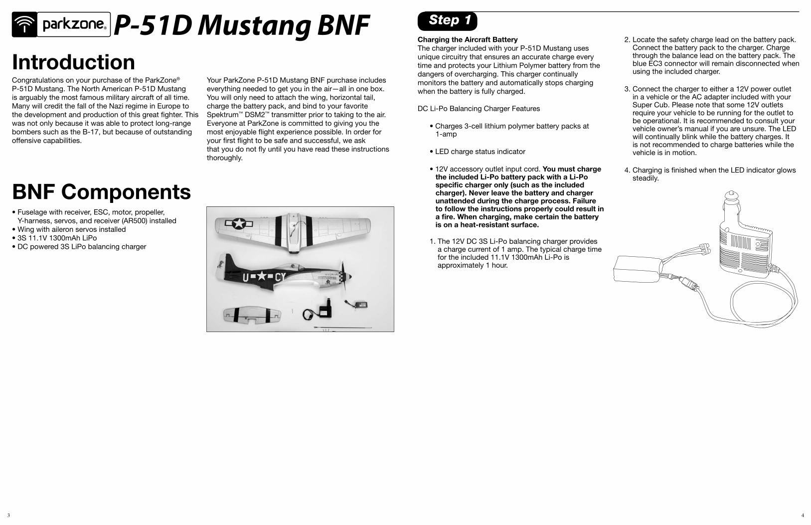
• Fuselage with receiver, ESC, motor, propeller, Y-harness, servos, and receiver (AR500) installed
• Wing with aileron servos installed• 3S 11.1V 1300mAh LiPo• DC powered 3S LiPo balancing charger
5 6
Step 3Transmitter Specific Binding Instructions
DX5e:A. To bind your P-51D Mustang to the DX5e, plug
the bind plug into the Batt/Bind port on the AR500 receiver.
B. Plug the battery into the ESC of the airplane. The LED on the receiver will begin flashing.
C. Move the sticks and switches on the transmitter to the desired failsafe positions (low throttle and neutral control positions).
D. Pull and hold the Trainer Switch on the transmitter while turning the transmitter on. Release the trainer switch once the LEDs on the front of the transmitter flash.
E. The LED on the receiver will go solid amber and the system will connect after several seconds.
DX6i:A. To bind your P-51D Mustang to the DX6i, plug the
bind plug into the Batt/Bind port on the AR500 receiver.
B. Plug the battery into the ESC of the airplane. The LED on the receiver will begin flashing.
C. Move the sticks and switches on the transmitter to the desired failsafe positions (low throttle and neutral control positions).
D. Pull and hold the Trainer Switch on the transmitter while turning the transmitter on. Release the trainer switch once the word BIND flashes on the LCD screen on the front of the transmitter.
E. The LED on the receiver will go solid amber and the system will connect after several seconds.
DX7 (includes DX7se):A. To bind your P-51D Mustang to the DX7, plug the
bind plug into the Batt/Bind port on the AR500 receiver.
B. Plug the battery into the ESC of the airplane. The
LED on the receiver will begin flashing.
C. Move the sticks and switches on the transmitter to the desired failsafe positions (low throttle and neutral control positions).
D. Press the bind button on the back of the transmitter while turning the transmitter on. The bind button on the back of the transmitter will flash. Release the button after 2-3 seconds.
E. The LED on the receiver will go solid amber and the system will connect after several seconds.
X9303:A. To bind your P-51D Mustang to the X9303, plug
the bind plug into the Batt/Bind port on the AR500 receiver.
B. Plug the battery into the ESC of the airplane. The
LED on the receiver will begin flashing.
C. Move the sticks and switches on the transmitter to the desired failsafe positions (low throttle and neutral control positions).
D. Press the bind button on the back of the transmitter while turning the transmitter on. The bind button on the back of the transmitter will flash. Release the button after 2-3 seconds.
E. The LED on the receiver will go solid amber and the system will connect after several seconds.
12X:A. To bind your P-51D Mustang to the 12X, plug
the bind plug into the Batt/Bind port on the AR500 receiver.
B. Plug the battery into the ESC of the airplane. The LED on the receiver will begin flashing.
C. Move the sticks and switches on the transmitter to the desired failsafe positions (low throttle and neutral control positions).
D. Press the black bind button on the back of the transmitter while turning the transmitter on. Release the button after 2-3 seconds.
E. The LED on the receiver will go solid amber and the system will connect after several seconds.
Step 2Transmitter and Receiver BindingBinding is the process of programming the receiver of the control unit to recognize the GUID (Globally Unique Identifier) code of a single specific transmitter. It will be necessary for you to ‘bind’ your chosen Spektrum DSM2 technology equipped transmitter to the receiver for proper operation.
The transmitter you select must be a DSM2 full range (high power) Tx>. The following is a list of some of the Spektrum DSM2 equipped transmitters and modules that will bind to the receiver of the P-51D Mustang:
Spektrum DX5e Spektrum DX6i Spektrum DX7 JR X9303 2.4 JR 12X 2.4
Note: The Spektrum DX6 (SPM2460) is equipped with DSM (not DSM2) technology and is not compatible with the receiver of the P-51D Mustang.
The following steps outline the binding process:
• Confirm the process of entering the bind mode for your chosen transmitter by reviewing the instruction manual included with the transmitter.
• Make sure the flight battery is disconnected from the receiver unit and the transmitter is turned off.
• Plug the bind plug into the Batt/Bind port on the AR500 receiver.
• Plug the flight battery into the battery lead of the ESC. The LED on the receiver unit will begin flashing.
Note: NEVER plug the balance lead of the battery directly into the receiver. This will cause damage to the receiver and battery.
• After verifying the LED is flashing on the receiver, follow the steps that allow your chosen transmitter to enter bind mode.
• If you entered bind mode correctly, you will see a solid LED approximately 5–10 seconds later on the receiver. You should now be bound to the transmitter, and have full control and function.
If you encounter any problems, repeat the binding process again, see the troubleshooting guide or call the Horizon Support Team at 1-877-504-0233.
7 8
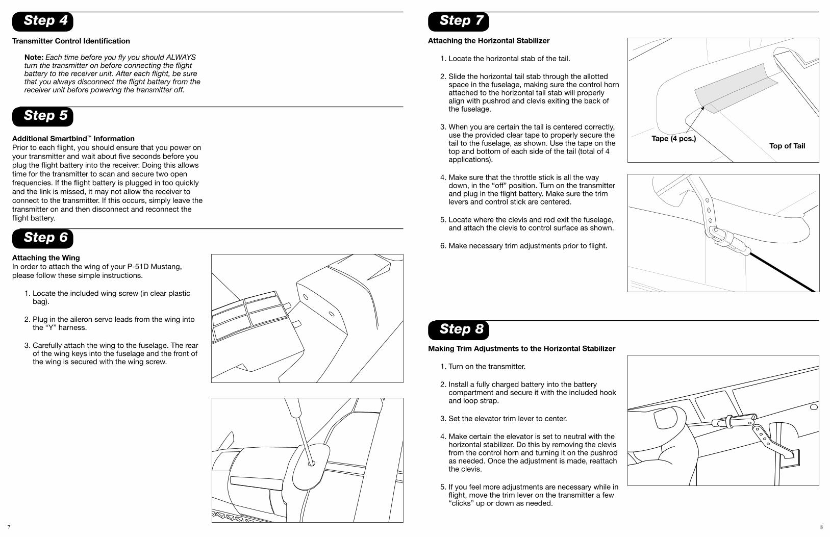
Step 7Attaching the Horizontal Stabilizer
1. Locate the horizontal stab of the tail.
2. Slide the horizontal tail stab through the allotted space in the fuselage, making sure the control horn attached to the horizontal tail stab will properly align with pushrod and clevis exiting the back of the fuselage.
3. When you are certain the tail is centered correctly, use the provided clear tape to properly secure the tail to the fuselage, as shown. Use the tape on the top and bottom of each side of the tail (total of 4 applications).
4. Make sure that the throttle stick is all the way down, in the “off” position. Turn on the transmitter and plug in the flight battery. Make sure the trim levers and control stick are centered.
5. Locate where the clevis and rod exit the fuselage, and attach the clevis to control surface as shown.
6. Make necessary trim adjustments prior to flight.
Top of TailTape (4 pcs.)
Step 8Making Trim Adjustments to the Horizontal Stabilizer
1. Turn on the transmitter.
2. Install a fully charged battery into the battery compartment and secure it with the included hook and loop strap.
3. Set the elevator trim lever to center.
4. Make certain the elevator is set to neutral with the horizontal stabilizer. Do this by removing the clevis from the control horn and turning it on the pushrod as needed. Once the adjustment is made, reattach the clevis.
5. If you feel more adjustments are necessary while in flight, move the trim lever on the transmitter a few “clicks” up or down as needed.
Step 4
Step 5
Transmitter Control Identification
Note: Each time before you fly you should ALWAYS turn the transmitter on before connecting the flight battery to the receiver unit. After each flight, be sure that you always disconnect the flight battery from the receiver unit before powering the transmitter off.
Additional Smartbind™ InformationPrior to each flight, you should ensure that you power on your transmitter and wait about five seconds before you plug the flight battery into the receiver. Doing this allows time for the transmitter to scan and secure two open frequencies. If the flight battery is plugged in too quickly and the link is missed, it may not allow the receiver to connect to the transmitter. If this occurs, simply leave the transmitter on and then disconnect and reconnect the flight battery.
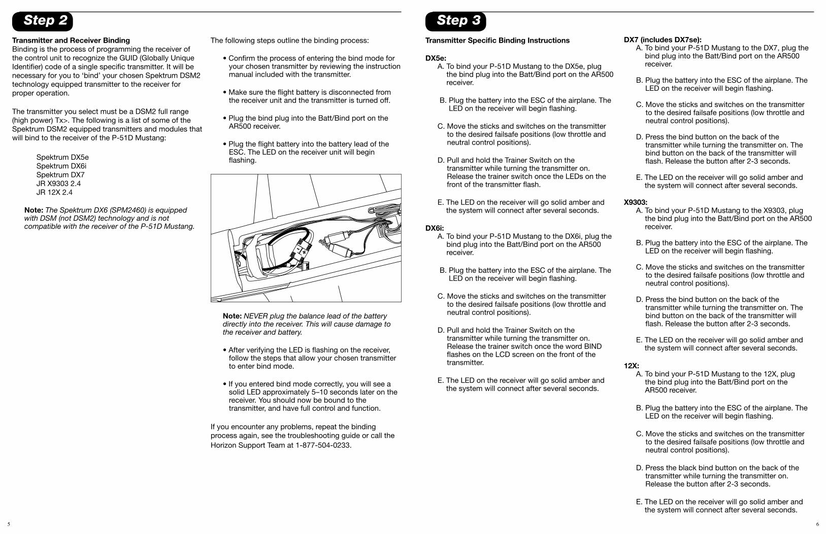
Step 6Attaching the WingIn order to attach the wing of your P-51D Mustang, please follow these simple instructions.
1. Locate the included wing screw (in clear plastic bag).
2. Plug in the aileron servo leads from the wing into the “Y” harness.
3. Carefully attach the wing to the fuselage. The rear of the wing keys into the fuselage and the front of the wing is secured with the wing screw.
9 10
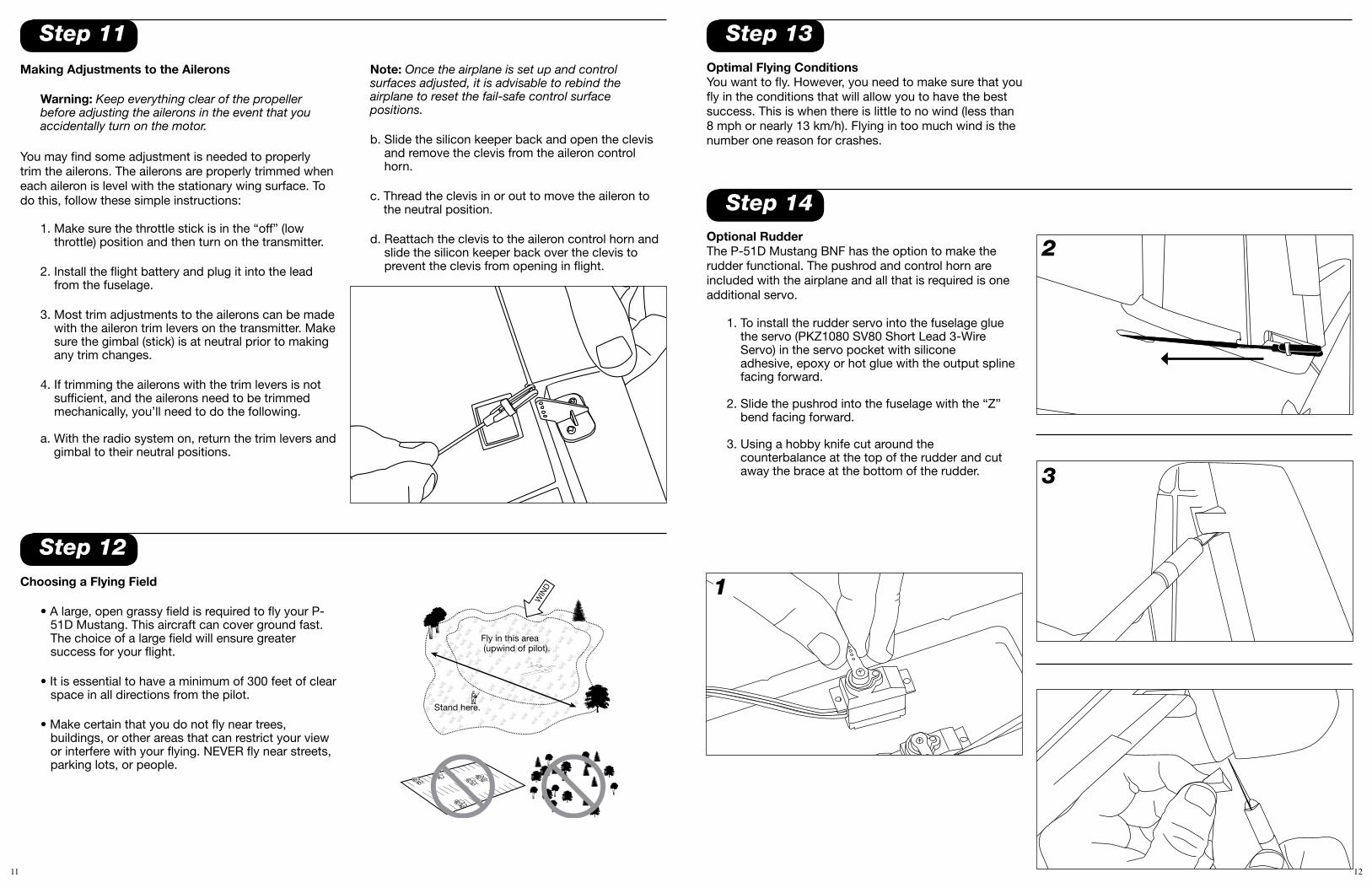
Step 10Control Test
Warning: Keep everything clear of the propeller before starting the control test in the event that you accidentally turn on the motor.
Note: If you are using a Spektrum or JR DSM radio, you are going to have to reverse the ailerons on the transmitter prior to flying. Failure to do this will result in the ailerons being reversed and will likely result in a crash.
1. Be certain that the throttle stick is in the “off” (low throttle) position and that both trim levers are centered.
2. Switch on the transmitter and check to make sure the transmitter has power.
3. Install the flight battery into the fuselage and plug it into the battery connector.
4. Move the stick from side to side. The ailerons on the trailing edge of the wings should move per your transmitter input. When the stick is pushed to the right, the right aileron should deflect upward and the left aileron downward, and vice versa.
5. Pull the stick back and the elevator control surface should move upward (as shown).
6. Move the stick full forward. When this is done, the elevator control surface should move down (as shown).
7. When the test is complete, be sure to disconnect the flight battery first, and then turn off the transmitter. This should be done each time you turn off the airplane.
Note: It is very important to make sure that the control surfaces are at 0 degrees when the transmitter control stick and trim levers are centered. (See Steps 5 and 8 for making needed adjustments to control surfaces.)
If your airplane is not responding correctly to the transmitter input, do not fly! Some correction is needed. Call the Horizon Support Team line at 1-877-504-0233.
Note: Transmitter below reflects Mode 2 only
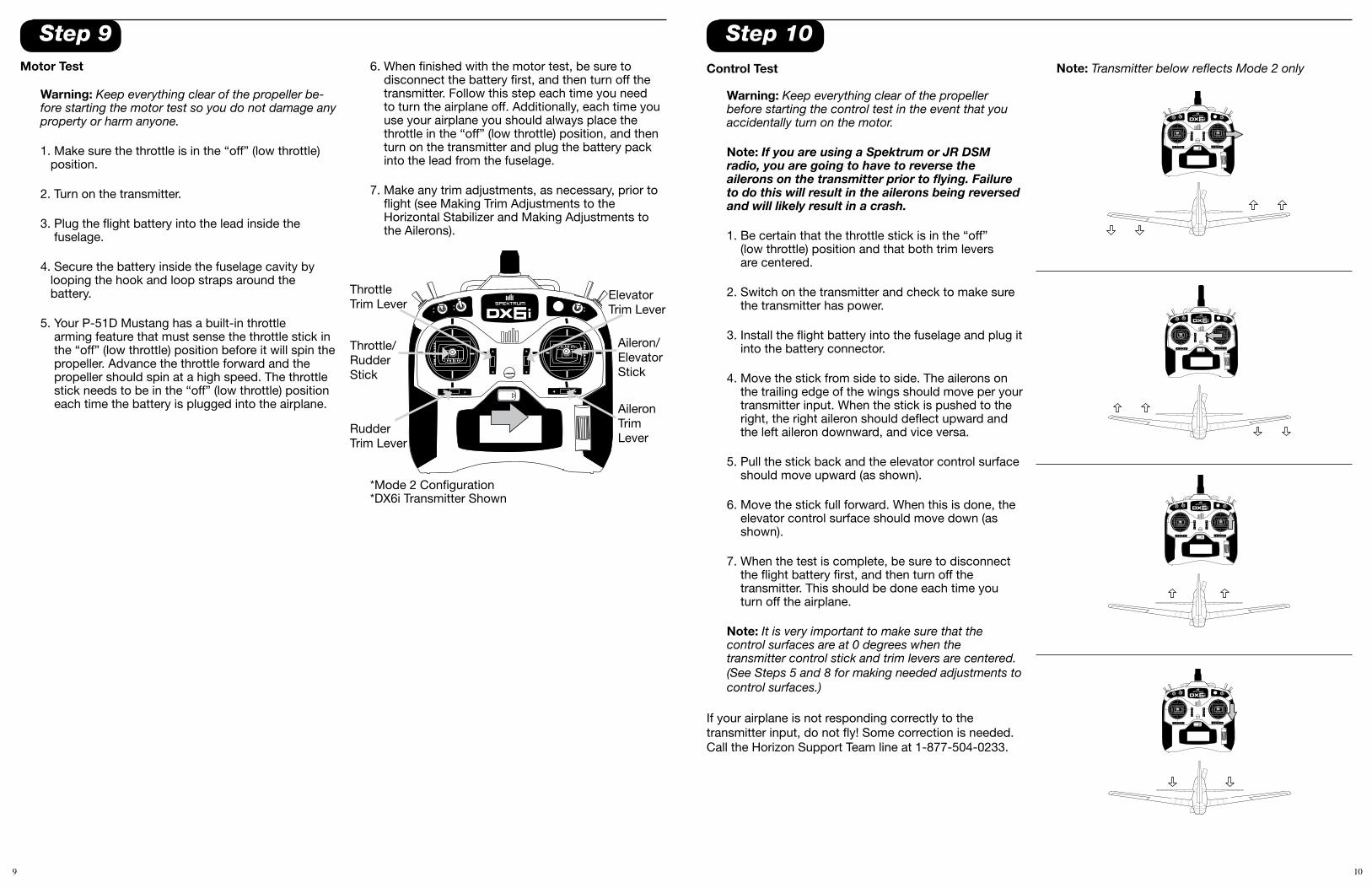
Step 9Motor Test
Warning: Keep everything clear of the propeller be-fore starting the motor test so you do not damage any property or harm anyone.
1. Make sure the throttle is in the “off” (low throttle) position.
2. Turn on the transmitter.
3. Plug the flight battery into the lead inside the fuselage.
4. Secure the battery inside the fuselage cavity by looping the hook and loop straps around the battery.
5. Your P-51D Mustang has a built-in throttle arming feature that must sense the throttle stick in the “off” (low throttle) position before it will spin the propeller. Advance the throttle forward and the propeller should spin at a high speed. The throttle stick needs to be in the “off” (low throttle) position each time the battery is plugged into the airplane.
6. When finished with the motor test, be sure to disconnect the battery first, and then turn off the transmitter. Follow this step each time you need to turn the airplane off. Additionally, each time you use your airplane you should always place the throttle in the “off” (low throttle) position, and then turn on the transmitter and plug the battery pack into the lead from the fuselage.
7. Make any trim adjustments, as necessary, prior to flight (see Making Trim Adjustments to the Horizontal Stabilizer and Making Adjustments to the Ailerons).
Aileron/Elevator Stick
Rudder Trim Lever
Throttle Trim Lever
Throttle/Rudder Stick
Elevator Trim Lever
AileronTrim Lever
*Mode 2 Configuration*DX6i Transmitter Shown
11 12
Step 12
Step 13
Step 14
Optimal Flying ConditionsYou want to fly. However, you need to make sure that you fly in the conditions that will allow you to have the best success. This is when there is little to no wind (less than 8 mph or nearly 13 km/h). Flying in too much wind is the number one reason for crashes.
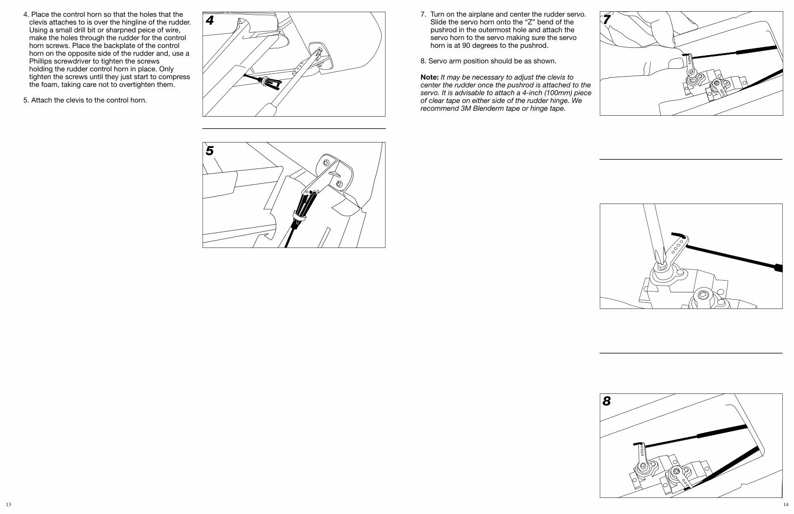
Optional RudderThe P-51D Mustang BNF has the option to make the rudder functional. The pushrod and control horn are included with the airplane and all that is required is one additional servo.
1. To install the rudder servo into the fuselage glue the servo (PKZ1080 SV80 Short Lead 3-Wire Servo) in the servo pocket with silicone adhesive, epoxy or hot glue with the output spline facing forward.
2. Slide the pushrod into the fuselage with the “Z” bend facing forward.
3. Using a hobby knife cut around the counterbalance at the top of the rudder and cut away the brace at the bottom of the rudder.
Step 11Making Adjustments to the Ailerons
Warning: Keep everything clear of the propeller before adjusting the ailerons in the event that you accidentally turn on the motor.
You may find some adjustment is needed to properly trim the ailerons. The ailerons are properly trimmed when each aileron is level with the stationary wing surface. To do this, follow these simple instructions:
1. Make sure the throttle stick is in the “off” (low throttle) position and then turn on the transmitter.
2. Install the flight battery and plug it into the lead from the fuselage.
3. Most trim adjustments to the ailerons can be made with the aileron trim levers on the transmitter. Make sure the gimbal (stick) is at neutral prior to making any trim changes.
4. If trimming the ailerons with the trim levers is not sufficient, and the ailerons need to be trimmed mechanically, you’ll need to do the following.
a. With the radio system on, return the trim levers and gimbal to their neutral positions.
Note: Once the airplane is set up and control surfaces adjusted, it is advisable to rebind the airplane to reset the fail-safe control surface positions.
b. Slide the silicon keeper back and open the clevis and remove the clevis from the aileron control horn.
c. Thread the clevis in or out to move the aileron to the neutral position.
d. Reattach the clevis to the aileron control horn and slide the silicon keeper back over the clevis to prevent the clevis from opening in flight.
Choosing a Flying Field
• A large, open grassy field is required to fly your P-51D Mustang. This aircraft can cover ground fast. The choice of a large field will ensure greater success for your flight.
• It is essential to have a minimum of 300 feet of clear space in all directions from the pilot.
• Make certain that you do not fly near trees, buildings, or other areas that can restrict your view or interfere with your flying. NEVER fly near streets, parking lots, or people.
Fly in this area (upwind of pilot).
Stand here.
WIN
D
2
3
1
13 14
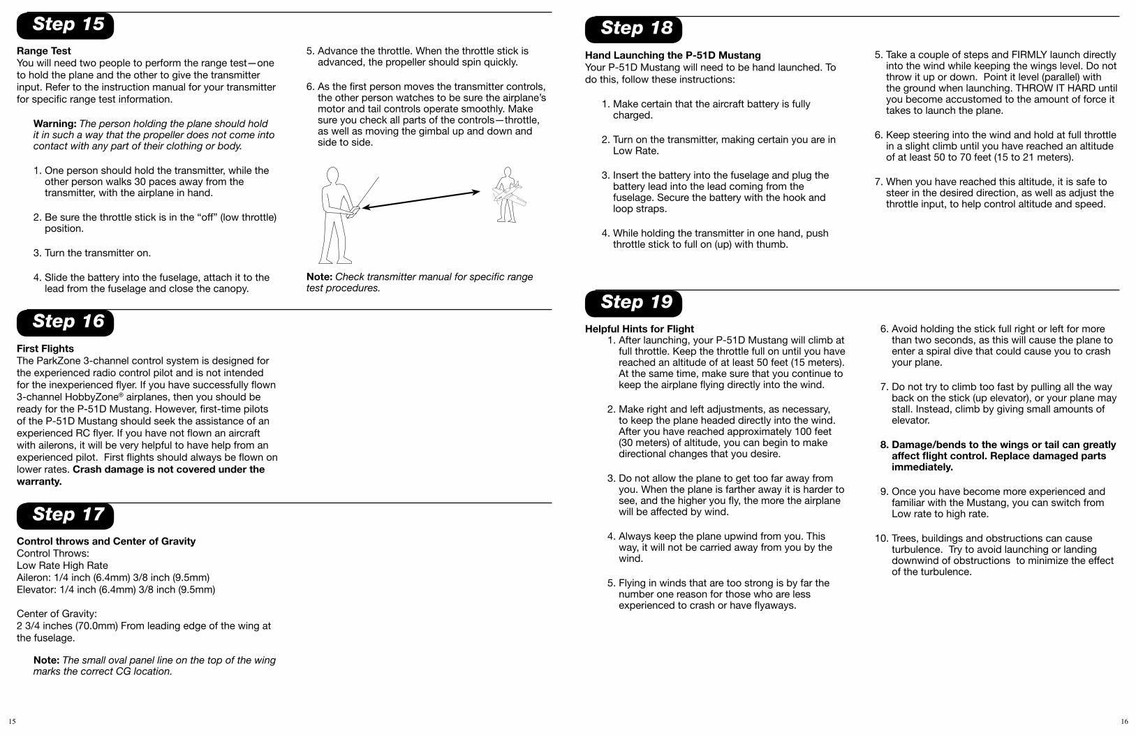
4. Place the control horn so that the holes that the clevis attaches to is over the hingline of the rudder.Using a small drill bit or sharpned peice of wire, make the holes through the rudder for the control horn screws. Place the backplate of the control horn on the opposite side of the rudder and, use a Phillips screwdriver to tighten the screws holding the rudder control horn in place. Only tighten the screws until they just start to compress the foam, taking care not to overtighten them.
5. Attach the clevis to the control horn.
7. Turn on the airplane and center the rudder servo. Slide the servo horn onto the “Z” bend of the pushrod in the outermost hole and attach the servo horn to the servo making sure the servo horn is at 90 degrees to the pushrod.
8. Servo arm position should be as shown.
Note: It may be necessary to adjust the clevis to center the rudder once the pushrod is attached to the servo. It is advisable to attach a 4-inch (100mm) piece of clear tape on either side of the rudder hinge. We recommend 3M Blenderm tape or hinge tape.
4
5
7
8
15 16
5. Advance the throttle. When the throttle stick is advanced, the propeller should spin quickly.
6. As the first person moves the transmitter controls, the other person watches to be sure the airplane’s motor and tail controls operate smoothly. Make sure you check all parts of the controls—throttle, as well as moving the gimbal up and down and side to side.
Note: Check transmitter manual for specific range test procedures.
First FlightsThe ParkZone 3-channel control system is designed for the experienced radio control pilot and is not intended for the inexperienced flyer. If you have successfully flown 3-channel HobbyZone® airplanes, then you should be ready for the P-51D Mustang. However, first-time pilots of the P-51D Mustang should seek the assistance of an experienced RC flyer. If you have not flown an aircraft with ailerons, it will be very helpful to have help from an experienced pilot. First flights should always be flown on lower rates. Crash damage is not covered under the warranty.
Control throws and Center of GravityControl Throws:Low Rate High RateAileron: 1/4 inch (6.4mm) 3/8 inch (9.5mm)Elevator: 1/4 inch (6.4mm) 3/8 inch (9.5mm)
Center of Gravity:2 3/4 inches (70.0mm) From leading edge of the wing at the fuselage.
Note: The small oval panel line on the top of the wing marks the correct CG location.
Step 16
Step 18
Step 17
Step 19
Range TestYou will need two people to perform the range test—one to hold the plane and the other to give the transmitter input. Refer to the instruction manual for your transmitter for specific range test information.
Warning: The person holding the plane should hold it in such a way that the propeller does not come into contact with any part of their clothing or body.
1. One person should hold the transmitter, while the other person walks 30 paces away from the transmitter, with the airplane in hand.
2. Be sure the throttle stick is in the “off” (low throttle) position.
3. Turn the transmitter on.
4. Slide the battery into the fuselage, attach it to the lead from the fuselage and close the canopy.
Helpful Hints for Flight 1. After launching, your P-51D Mustang will climb at
full throttle. Keep the throttle full on until you have reached an altitude of at least 50 feet (15 meters). At the same time, make sure that you continue to keep the airplane flying directly into the wind.
2. Make right and left adjustments, as necessary, to keep the plane headed directly into the wind. After you have reached approximately 100 feet (30 meters) of altitude, you can begin to make directional changes that you desire.
3. Do not allow the plane to get too far away from you. When the plane is farther away it is harder to see, and the higher you fly, the more the airplane will be affected by wind.
4. Always keep the plane upwind from you. This way, it will not be carried away from you by the wind.
5. Flying in winds that are too strong is by far the number one reason for those who are less experienced to crash or have flyaways.
Step 15
Hand Launching the P-51D MustangYour P-51D Mustang will need to be hand launched. To do this, follow these instructions:
1. Make certain that the aircraft battery is fully charged.
2. Turn on the transmitter, making certain you are in Low Rate.
3. Insert the battery into the fuselage and plug the battery lead into the lead coming from the fuselage. Secure the battery with the hook and loop straps.
4. While holding the transmitter in one hand, push throttle stick to full on (up) with thumb.
5. Take a couple of steps and FIRMLY launch directly into the wind while keeping the wings level. Do not throw it up or down. Point it level (parallel) with the ground when launching. THROW IT HARD until you become accustomed to the amount of force it takes to launch the plane.
6. Keep steering into the wind and hold at full throttle in a slight climb until you have reached an altitude of at least 50 to 70 feet (15 to 21 meters).
7. When you have reached this altitude, it is safe to steer in the desired direction, as well as adjust the throttle input, to help control altitude and speed.
6. Avoid holding the stick full right or left for more than two seconds, as this will cause the plane to enter a spiral dive that could cause you to crash your plane.
7. Do not try to climb too fast by pulling all the way back on the stick (up elevator), or your plane may stall. Instead, climb by giving small amounts of elevator.
8. Damage/bends to the wings or tail can greatly affect flight control. Replace damaged parts immediately.
9. Once you have become more experienced and familiar with the Mustang, you can switch from Low rate to high rate.
10. Trees, buildings and obstructions can cause turbulence. Try to avoid launching or landing downwind of obstructions to minimize the effect of the turbulence.
17 18
1. Don’t fly in winds over 10 mph! If you are a less experienced pilot, this is especially important.
2. A pilot who has never flown a 3-channel plane with pitch control should get help from an experienced radio control pilot during first flights. Pilots who have not flown a 3-channel plane at all should not fly unless an experienced RC pilot is present to guide them.
3. Choose your flying field carefully—grass and soft ground with a 600-foot (183-meter) diameter of open space is optimal for flying and will lengthen the life of your airplane. Make sure there are no obstacles that will get in your way when flying, such as trees or buildings. Make sure you do not fly where there are pedestrians who could be hurt by the airplane.
4. Remember that holding the stick full over for too long can cause the airplane to spiral dive and crash. At the very first sign of the plane beginning to spiral down, immediately release the stick and give the opposite turn control to the spiral, then pull back on the elevator gently to level flight and level the wings.
Success Tipsdoes not occur to the battery, charger or any other property. While charging, place the battery on a heat-resistant surface. Do not lay it on carpet or upholstery while charging.
6. Never cut into the battery, charger, or airplane wires or serious injury may occur. Causing the battery to “short out” (crossing negative and positive bare wires) can cause fire, serious injury and damage.
7. Hold the plane securely when the flight battery is plugged in, and keep all body parts away from the propeller. When you finish flying your airplane, always unplug the battery before you turn off the transmitter.
8. NEVER plug the balance lead of the battery directly into the receiver. This will cause damage to the receiver and battery.
9. The 18-amp ESC included with this airplane is specifically designed for this power system. If the power system is upgraded or larger propellers are used, we recommend the E-flite 30-amp ESC (EFLA1030).
10. Never leave the airplane in direct sunlight (when not in flight). Failure to do this can result in damage to the foam.
Warnings and Safety1. Read and follow this manual completely,
observing all instructions and safety directions. Otherwise, serious injury and damage can occur. Think about your safety, and the safety of others, first.
2. Keep the propeller away from body parts and clothing, even when it isn’t spinning, as it could be turned on by accident. Beware of hair becoming entangled in the propeller, especially while launching your plane.
3. Do not fly when it’s too windy or you may lose control and crash, causing injury or damage. Never fly near people, vehicles, train tracks, buildings, power lines, water, hard surfaces or trees. Never allow anyone to attempt to catch the airplane while it’s in flight or serious injury may result.
4. Age Recommendation: 14 years or over. This is not a toy. This product is not intended for use by children without direct adult supervision.
5. Only use a battery charger that is Lithium Polymer compatible to charge the flight battery. Never leave the charger unattended while charging. This will help prevent overcharging and make sure damage
5. Don’t attempt to fly or do maneuvers beyond your flying abilities. Seek the assistance of an experienced pilot when trying new maneuvers that are more extreme and involve fast flight.
6. If you’re gliding with the motor off, allow your plane more area for turns.
7. Position yourself at your flying field so that you keep the sun at your back and out of your eyes. Wear sunglasses on bright days.
8. Keep the aircraft upwind, especially on windier days, to prevent it from “flying away.” The wind is normally stronger at higher altitudes than it is on the ground.
9. Keep your plane in front of you so you don’t have to turn in circles as you fly. Try to avoid flying directly overhead.
19 20
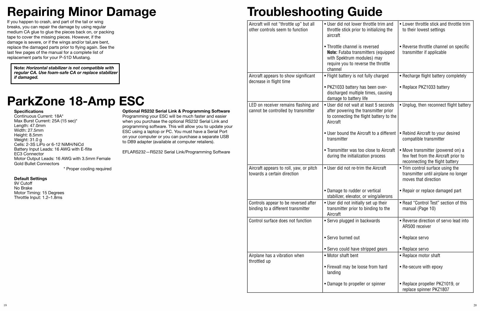
Troubleshooting GuideAircraft will not “throttle up” but all other controls seem to function
• User did not lower throttle trim and throttle stick prior to initializing the aircraft
• Throttle channel is reversed Note: Futaba transmitters (equipped with Spektrum modules) may require you to reverse the throttle channel
• Lower throttle stick and throttle trim to their lowest settings
• Reverse throttle channel on specific transmitter if applicable
Aircraft appears to show significant decrease in flight time
• Flight battery is not fully charged
• PKZ1033 battery has been over-discharged multiple times, causing damage to battery life
• Recharge flight battery completely
• Replace PKZ1033 battery
LED on receiver remains flashing and cannot be controlled by transmitter
• User did not wait at least 5 seconds after powering the transmitter prior to connecting the flight battery to the Aircraft
• User bound the Aircraft to a different transmitter
• Transmitter was too close to Aircraft during the initialization process
• Unplug, then reconnect flight battery
• Rebind Aircraft to your desired compatible transmitter
• Move transmitter (powered on) a few feet from the Aircraft prior to reconnecting the flight battery
Aircraft appears to roll, yaw, or pitch towards a certain direction
• User did not re-trim the Aircraft
• Damage to rudder or vertical stabilizer, elevator, or wing/ailerons
• Trim control surface using the transmitter until airplane no longer moves that direction
• Repair or replace damaged part
Controls appear to be reversed after binding to a different transmitter
• User did not initially set up their transmitter prior to binding to the Aircraft
• Read “Control Test” section of this manual (Page 10)
Control surface does not function • Servo plugged in backwards
• Servo burned out
• Servo could have stripped gears
• Reverse direction of servo lead into AR500 receiver
• Replace servo
• Replace servoAirplane has a vibration when throttled up
• Motor shaft bent
• Firewall may be loose from hard landing
• Damage to propeller or spinner
• Replace motor shaft
• Re-secure with epoxy
• Replace propeller PKZ1019, or replace spinner PKZ1807
Repairing Minor Damage
ParkZone 18-Amp ESC
If you happen to crash, and part of the tail or wing breaks, you can repair the damage by using regular medium CA glue to glue the pieces back on, or packing tape to cover the missing pieces. However, if the damage is severe, or if the wings and/or tail,are bent, replace the damaged parts prior to flying again. See the last few pages of the manual for a complete list of replacement parts for your P-51D Mustang.
Note: Horizontal stabilizer is not compatible with regular CA. Use foam-safe CA or replace stabilizer if damaged.
SpecificationsContinuous Current: 18A*Max Burst Current: 25A (15 sec)*Length: 47.0mm Width: 27.5mmHeight: 8.5mmWeight: 31.0 gCells: 2-3S LiPo or 6-12 NiMH/NiCdBattery Input Leads: 16 AWG with E-fliteEC3 ConnectorMotor Output Leads: 16 AWG with 3.5mm FemaleGold Bullet Connectors
* Proper cooling required
Default Settings9V CutoffNo BrakeMotor Timing: 15 DegreesThrottle Input: 1.2–1.8ms
Optional RS232 Serial Link & Programming SoftwareProgramming your ESC will be much faster and easier when you purchase the optional RS232 Serial Link and programming software. This will allow you to update your ESC using a laptop or PC. You must have a Serial Port on your computer or you can purchase a separate USB to DB9 adapter (available at computer retailers).
EFLARS232—RS232 Serial Link/Programming Software
21 22
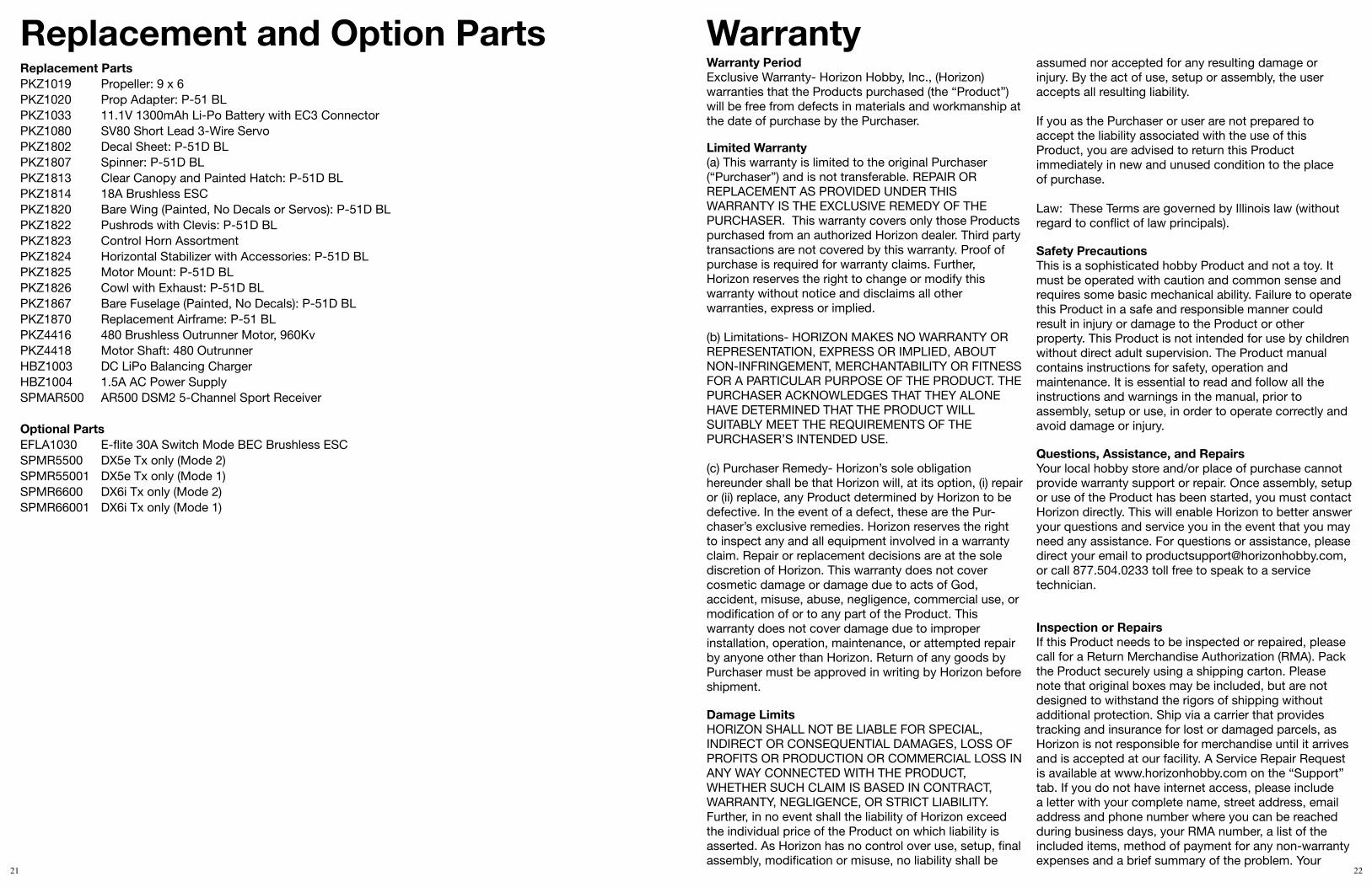
WarrantyWarranty PeriodExclusive Warranty- Horizon Hobby, Inc., (Horizon) warranties that the Products purchased (the “Product”) will be free from defects in materials and workmanship at the date of purchase by the Purchaser.
Limited Warranty(a) This warranty is limited to the original Purchaser (“Purchaser”) and is not transferable. REPAIR OR REPLACEMENT AS PROVIDED UNDER THIS WARRANTY IS THE EXCLUSIVE REMEDY OF THE PURCHASER. This warranty covers only those Products purchased from an authorized Horizon dealer. Third party transactions are not covered by this warranty. Proof of purchase is required for warranty claims. Further, Horizon reserves the right to change or modify this warranty without notice and disclaims all other warranties, express or implied.
(b) Limitations- HORIZON MAKES NO WARRANTY OR REPRESENTATION, EXPRESS OR IMPLIED, ABOUT NON-INFRINGEMENT, MERCHANTABILITY OR FITNESS FOR A PARTICULAR PURPOSE OF THE PRODUCT. THE PURCHASER ACKNOWLEDGES THAT THEY ALONE HAVE DETERMINED THAT THE PRODUCT WILL SUITABLY MEET THE REQUIREMENTS OF THE PURCHASER’S INTENDED USE.
(c) Purchaser Remedy- Horizon’s sole obligation hereunder shall be that Horizon will, at its option, (i) repair or (ii) replace, any Product determined by Horizon to be defective. In the event of a defect, these are the Pur-chaser’s exclusive remedies. Horizon reserves the right to inspect any and all equipment involved in a warranty claim. Repair or replacement decisions are at the sole discretion of Horizon. This warranty does not cover cosmetic damage or damage due to acts of God, accident, misuse, abuse, negligence, commercial use, or modification of or to any part of the Product. This warranty does not cover damage due to improper installation, operation, maintenance, or attempted repair by anyone other than Horizon. Return of any goods by Purchaser must be approved in writing by Horizon before shipment.
Damage LimitsHORIZON SHALL NOT BE LIABLE FOR SPECIAL, INDIRECT OR CONSEQUENTIAL DAMAGES, LOSS OF PROFITS OR PRODUCTION OR COMMERCIAL LOSS IN ANY WAY CONNECTED WITH THE PRODUCT, WHETHER SUCH CLAIM IS BASED IN CONTRACT, WARRANTY, NEGLIGENCE, OR STRICT LIABILITY. Further, in no event shall the liability of Horizon exceed the individual price of the Product on which liability is asserted. As Horizon has no control over use, setup, final assembly, modification or misuse, no liability shall be
assumed nor accepted for any resulting damage or injury. By the act of use, setup or assembly, the user accepts all resulting liability.
If you as the Purchaser or user are not prepared to accept the liability associated with the use of this Product, you are advised to return this Product immediately in new and unused condition to the place of purchase.
Law: These Terms are governed by Illinois law (without regard to conflict of law principals). Safety PrecautionsThis is a sophisticated hobby Product and not a toy. It must be operated with caution and common sense and requires some basic mechanical ability. Failure to operate this Product in a safe and responsible manner could result in injury or damage to the Product or other property. This Product is not intended for use by children without direct adult supervision. The Product manual contains instructions for safety, operation and maintenance. It is essential to read and follow all the instructions and warnings in the manual, prior to assembly, setup or use, in order to operate correctly and avoid damage or injury. Questions, Assistance, and RepairsYour local hobby store and/or place of purchase cannot provide warranty support or repair. Once assembly, setup or use of the Product has been started, you must contact Horizon directly. This will enable Horizon to better answer your questions and service you in the event that you may need any assistance. For questions or assistance, please direct your email to [email protected], or call 877.504.0233 toll free to speak to a service technician.
Inspection or RepairsIf this Product needs to be inspected or repaired, please call for a Return Merchandise Authorization (RMA). Pack the Product securely using a shipping carton. Please note that original boxes may be included, but are not designed to withstand the rigors of shipping without additional protection. Ship via a carrier that provides tracking and insurance for lost or damaged parcels, as Horizon is not responsible for merchandise until it arrives and is accepted at our facility. A Service Repair Request is available at www.horizonhobby.com on the “Support” tab. If you do not have internet access, please include a letter with your complete name, street address, email address and phone number where you can be reached during business days, your RMA number, a list of the included items, method of payment for any non-warranty expenses and a brief summary of the problem. Your
Replacement and Option PartsReplacement PartsPKZ1019 Propeller: 9 x 6PKZ1020 Prop Adapter: P-51 BLPKZ1033 11.1V 1300mAh Li-Po Battery with EC3 ConnectorPKZ1080 SV80 Short Lead 3-Wire Servo PKZ1802 Decal Sheet: P-51D BL PKZ1807 Spinner: P-51D BL PKZ1813 Clear Canopy and Painted Hatch: P-51D BL PKZ1814 18A Brushless ESC PKZ1820 Bare Wing (Painted, No Decals or Servos): P-51D BL PKZ1822 Pushrods with Clevis: P-51D BLPKZ1823 Control Horn Assortment PKZ1824 Horizontal Stabilizer with Accessories: P-51D BL PKZ1825 Motor Mount: P-51D BLPKZ1826 Cowl with Exhaust: P-51D BL PKZ1867 Bare Fuselage (Painted, No Decals): P-51D BLPKZ1870 Replacement Airframe: P-51 BL PKZ4416 480 Brushless Outrunner Motor, 960KvPKZ4418 Motor Shaft: 480 OutrunnerHBZ1003 DC LiPo Balancing ChargerHBZ1004 1.5A AC Power SupplySPMAR500 AR500 DSM2 5-Channel Sport Receiver
Optional PartsEFLA1030 E-flite 30A Switch Mode BEC Brushless ESCSPMR5500 DX5e Tx only (Mode 2)SPMR55001 DX5e Tx only (Mode 1)SPMR6600 DX6i Tx only (Mode 2)SPMR66001 DX6i Tx only (Mode 1)

23 24
CE Compliance Information for the European Union
Instructions for Disposal of WEEE by Users in the European UnionThis product must not be disposed of with other waste. Instead, it is the user’s responsibility to dispose of their waste equipment by handing it over to a designated collections point for the recycling of waste electrical and electronic equipment. The separate collection and recycling of your waste equipment at the time of disposal will help to conserve natural resources and ensure that it is recycled in a manner that protects human health and the environment. For more information about where you can drop off your waste
equipment for recycling, please contact your local city office, your household waste disposal service or where you purchased the product.
Declaration of Conformity(in accordance with ISO/IEC 17050-1)
No. HH2009051302
Product(s): ParkZone P-51 BL BNF Item Number(s): PKZ1880 Equipment class: 1
The objects of declaration described above are in conformity with the requirements of the specifications listed below, following the provisions of the European R&TTE directive 1999/5/EC:
EN 301 489-1, 301 489-3 General EMC requirements for Radio equipmentEN 301 489-17 v.1.2.1
Signed for and on behalf of:Horizon Hobby, Inc.Champaign, IL USAMay 13,2009 Steven A. Hall
Vice President International Operations and Risk Management Horizon Hobby, Inc.
original sales receipt must also be included for warranty consideration. Be sure your name, address, and RMA number are clearly written on the outside of the shipping carton.
Warranty Inspection and RepairsTo receive warranty service, you must include your original sales receipt verifying the proof-of-purchase date. Provided warranty conditions have been met, your Product will be repaired or replaced free of charge. Repair or replacement decisions are at the sole discretion of Horizon Hobby. Non-Warranty Repairs Should your repair not be covered by warranty the repair will be completed and payment will be required without notification or estimate of the expense unless the expense exceeds 50% of the retail purchase cost. By submitting the item for repair you are agreeing to payment of the repair without notification. Repair estimates are available upon request. You must include this request with your repair. Non-warranty repair estimates will be billed a minimum of ½ hour of labor. In addition you will be billed for return freight. Please advise us of your preferred method of payment. Horizon accepts money orders and cashiers checks, as well as Visa, MasterCard, American Express, and Discover cards. If you choose to pay by credit card, please include your credit card number and expiration date. Any repair left unpaid or unclaimed after 90 days will be considered abandoned and will be disposed of accordingly. Please note: non-warranty repair is only available on electronics and model engines.
United States:Electronics and engines requiring inspection or repair should be shipped to the following address:
Horizon Service Center4105 Fieldstone RoadChampaign, Illinois 61822
All other Products requiring warranty inspection or repair should be shipped to the following address:
Horizon Product Support4105 Fieldstone RoadChampaign, Illinois 61822
Please call 877-504-0233 or e-mail us at [email protected] with any questions or concerns regarding this product or warranty.
United Kingdom:Electronics and engines requiring inspection or repair should be shipped to the following address:
Horizon Hobby UKUnits 1-4 Ployters RdStaple TyeHarlow, EssexCM18 7NSUnited Kingdom
Please call +44 (0) 1279 641 097 or e-mail us at [email protected] with any questions or concerns regarding this product or warranty.
Germany:Electronics and engines requiring inspection or repair should be shipped to the following address:
Horizon Technischer ServiceHamburger Strasse 1025335 ElmshornGermany
Please call +49 4121 46199 66 or e-mail us [email protected] with any questions or concerns regarding this product or warranty.