p-19 oshkosh ultra high pressure (uhp) firefighting truck
TRANSCRIPT

DEPARTMENT OF THE AIR FORCE Headquarters US Air Force
QTP24-3-L145 26 March 2019
Washington, D.C. 20330-1030
P-19 Oshkosh Ultra High Pressure (UHP) Firefighting TruckVehicle Management Codes: L145
QUALIFICATION TRAINING PACKAGE

CONTENTS
SECTION 1—OVERVIEW ....................................................................................................................... 3 1.1. Overview. .......................................................................................................................................................................... 3
SECTION 2—RESPONSIBILITIES ........................................................................................................ 3 2.1. Responsibilities. ................................................................................................................................................................ 3
SECTION 3—INTRODUCTION .............................................................................................................. 4 3.1. Objectives. ......................................................................................................................................................................... 4
3.2. Desired Learning Outcome. ............................................................................................................................................. 5
3.3. Lesson Duration. .............................................................................................................................................................. 5
3.4. Instructional References. ................................................................................................................................................. 5
3.5. Instructional Training Aids and Equipment. ................................................................................................................. 6
SECTION 4—TRAINEE PREPARATION ............................................................................................. 7 4.1. Licensing Requirements................................................................................................................................................... 7
4.2. Required Reading (Testable Material). .......................................................................................................................... 7
SECTION 5—KNOWLEDGE LECTURE AND EVALUATION. ........................................................ 7 5.1. Knowledge Overview (Lecture). ...................................................................................................................................... 7
5.2. Overview of Training and Requirements. ...................................................................................................................... 7
5.3. Vehicle Inspection. ......................................................................................................................................................... 12
5.4. Vehicle Safety and Equipment. ..................................................................................................................................... 16
5.5. Driving Safety and Precautions. .................................................................................................................................... 17
5.6. P-19 Oshkosh UHP Firefighting Truck Vehicle Operation. ....................................................................................... 20
5.7. Firefighting Systems Operation. ................................................................................................................................... 22
5.8. Structural Systems Operation. ...................................................................................................................................... 24
5.9. Dry Chemical System Operation................................................................................................................................... 28
5.10. Agent Re-Servicing. ........................................................................................................................................................ 28
5.11. Dry Chemical Overview. ................................................................................................................................................ 31
SECTION 6—EXPLANATION AND DEMONSTRATION ............................................................... 33 6.1. Instructor’s Preparation. ............................................................................................................................................... 33
6.2. Safety Procedures and Equipment. ............................................................................................................................... 33
6.3. Operator Maintenance Demonstration......................................................................................................................... 34
6.4. Operation Demonstration. ............................................................................................................................................. 34
SECTION 7—TRAINEE PERFORMANCE AND EVALUATION ................................................... 36 7.1. Trainee Performance. .................................................................................................................................................... 36
7.2. Performance Evaluation. ............................................................................................................................................... 39
Attachment 1—GLOSSARY OF REFERENCES AND SUPPORTING INFORMATION 43
Attachment 2—SUBJECT KNOWLEDGE 45
Attachment 3—VEHICLE INSPECTION GUIDE 50
Attachment 4—PERFORMANCE TEST 54
Attachment 5—OPERATION & TROUBLESHOOTING GUIDE FOR THE AIR FORCE IDLE REDUCTION TECHNOLOGY (IRT) SYSTEM 57
Attachment 6—SEVEN-STEP INSPECTION PROCESS 61

Section 1—OVERVIEW 1.1. Overview.
1.1.1. Send comments and suggested improvements on AF Form 847, Recommendation for Change of Publication through Air Force Installation and Mission Support Center (AFIMSC) functional managers via e-mail at [email protected]. 1.1.2. How to use this plan:
1.1.2.1. Instructor:
1.1.2.1.1. Provide overview of training, Section 2 and Section 3. 1.1.2.1.2. Instructor’s lesson plan for trainee preparation, give classroom lecture, Section 4. 1.1.2.1.3. Instructor’s lesson plan for knowledge test, Section 5. 1.1.2.1.4. Instructor’s lesson plan for demonstration, Section 6. 1.1.2.1.5. Instructor’s lesson plan for performance and evaluation, Section 7.
1.1.2.2. Trainee:
1.1.2.2.1. Reads material entire lesson plan prior to classroom lecture. 1.1.2.2.2. Follows along with lecture using this lesson plan and its attachments. 1.1.2.2.3. Takes knowledge P-19 Oshkosh UHP Firefighting Truck and airbrakes tests. 1.1.2.2.4. Uses Attachment 3 as a guide for vehicle inspection. 1.1.2.2.5. Takes performance test, Attachment 4.
Section 2—RESPONSIBILITIES 2.1. Responsibilities.
2.1.1. The trainee shall:
2.1.1.1. Ensure the trainer explains the lesson plan process and the responsibilities. 2.1.1.2. Review the lesson plan/module/unit and the manufacturer’s operator’s manual with the trainer.

2.1.1.3. Ask questions if he/she does not understand the objectives for each unit. 2.1.1.4. Review missed questions with the trainer.
2.1.2. Instructor shall:
2.1.2.1. Review the lesson plan with the trainee. 2.1.2.2. Conduct knowledge training with the trainee using the lesson plan. 2.1.2.3. Grade the review questions using the answer key. 2.1.2.4. Review missed questions with the trainee to ensure the required task knowledge has been gained to complete the task. 2.1.2.5. Sign-off the task(s).
2.1.3. The Certifier shall:
2.1.3.1. Evaluate the Airman’s task performance without assistance. 2.1.3.2. Sign-off the task(s).
Section 3—INTRODUCTION 3.1. Objectives.
3.1.1. Given lectures, demonstrations, hands-on driving session and a performance and written test, trainees will be able to perform operator’s inspection and complete the performance test with zero instructor assists and achieve 80% on the written test. The written test for the P-19 Oshkosh UHP Firefighting Truck is located on the Civil Engineering Virtual Learning Center (CE-VLC).
3.1.1.1. Train and qualify each trainee in inspection, safe operation, preventive maintenance and resupply of the P-19 Oshkosh UHP Firefighting Truck. 3.1.1.2. This training will ensure the trainee becomes a qualified P-19 Oshkosh UHP Firefighting Truck operator; an operator who has the knowledge and skills to operate the P-19 Oshkosh UHP Firefighting Truck in a safe and professional manner. 3.1.1.3. Familiarize licensed personnel in the inspection, operation, and re-servicing of the P-19.
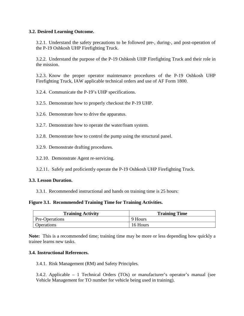
3.2. Desired Learning Outcome.
3.2.1. Understand the safety precautions to be followed pre-, during-, and post-operation of the P-19 Oshkosh UHP Firefighting Truck. 3.2.2. Understand the purpose of the P-19 Oshkosh UHP Firefighting Truck and their role in the mission. 3.2.3. Know the proper operator maintenance procedures of the P-19 Oshkosh UHP Firefighting Truck, IAW applicable technical orders and use of AF Form 1800. 3.2.4. Communicate the P-19’s UHP specifications. 3.2.5. Demonstrate how to properly checkout the P-19 UHP. 3.2.6. Demonstrate how to drive the apparatus. 3.2.7. Demonstrate how to operate the water/foam system. 3.2.8. Demonstrate how to control the pump using the structural panel. 3.2.9. Demonstrate drafting procedures. 3.2.10. Demonstrate Agent re-servicing. 3.2.11. Safely and proficiently operate the P-19 Oshkosh UHP Firefighting Truck.
3.3. Lesson Duration.
3.3.1. Recommended instructional and hands on training time is 25 hours:
Figure 3.1. Recommended Training Time for Training Activities.
Training Activity Training Time Pre-Operations 9 Hours Operations 16 Hours
Note: This is a recommended time; training time may be more or less depending how quickly a trainee learns new tasks.
3.4. Instructional References.
3.4.1. Risk Management (RM) and Safety Principles. 3.4.2. Applicable – 1 Technical Orders (TOs) or manufacturer’s operator’s manual (see Vehicle Management for TO number for vehicle being used in training).

3.4.3. AFMAN 24-306, Operation of Air Force Government Motor Vehicles. 3.4.4. AF Form 1800. 3.4.5. Code of Federal Regulations (CFR), Title 49—Transportation, Subtitle B—Other Regulations Relating to Transportation (Continued), Chapter III—Federal Motor Carrier Safety Administration, Department of Transportation, parts 300-399; on-line at http://www.access.gpo.gov/nara/cfr/cfr-table-search.html. 3.4.6. United States Department of Transportation, Federal Motor Carrier Safety Administration; on-line at http://www.fmcsa.dot.gov/index.htm. 3.4.7. Oshkosh Striker 1500 with Ultra High Pressure. 3.4.8. Oshkosh Striker Operator’s Manual/CD-Rom. 3.4.9. IFSTA Aircraft Rescue and Firefighting, Fourth Edition. 3.4.10. CDC 10027, Driver/Operator ARFF Performance Test. 3.4.11. National Fire Protection Association (NFPA) 1003, Standard for Airport Fire Fighter Professional Qualifications. 3.4.12. NFPA 1041, Standard for Fire Service Instructor Professional Qualifications. 3.4.13. NFPA 1403, Standard on Live Fire Training Evolutions. 3.4.14. NFPA 1500, Standard on Fire Department Occupational Safety and Health Program.
3.5. Instructional Training Aids and Equipment.
3.5.1. P-19 Oshkosh UHP Firefighting Truck Lesson Plan. 3.5.2. P-19 Oshkosh UHP Firefighting Truck. 3.5.3. Applicable TO or Manufacturer’s Operator’s Manual. 3.5.4. AF Form 1800. 3.5.5. Oshkosh Striker 1500 with Ultra High Pressure. 3.5.6. Oshkosh Striker Operator’s Manual/CD-Rom. 3.5.7. IFSTA Aircraft Rescue and Firefighting, Fourth Edition.

3.5.8. Videos (if locally produced). 3.5.9. Suitable training area. 3.5.10. Traffic cones.
Section 4—TRAINEE PREPARATION 4.1. Licensing Requirements.
4.1.1. Trainee must have in his/her possession a valid state driver’s license. 4.1.2. AF Form 171, Request for Driver’s Training and Addition to U.S. Government Drivers IAW AFI 24-301. 4.1.3. Applicable local licensing jurisdiction requirements.
4.2. Required Reading (Testable Material).
4.2.1. Read this lesson plan in its entirety. 4.2.2. Read AFMAN 24-306. 4.2.3. Read manufacturer’s operator’s manual for the vehicle being trained on.
Section 5—KNOWLEDGE LECTURE AND EVALUATION. 5.1. Knowledge Overview (Lecture).
5.1.1. The majority of the material below was written using the instructional references listed in Section 3. They have been expanded upon and modified to address the knowledge needs in accordance the role of the GMV operator under the mission and standards required by the USAF.
5.2. Overview of Training and Requirements.
5.2.1. Training objectives:
5.2.1.1. Given lectures, demonstrations, hands-on driving session and a performance and written test, trainees will be able to perform operator’s inspection and complete the performance test with zero instructor assists and achieve 80% on the written test on the CE-VLC. 5.2.1.2. Train and qualify each trainee in safe operation and preventive maintenance of the P-19 Oshkosh UHP Firefighting Truck.

5.2.1.3. This training will ensure the trainee becomes a qualified P-19 Oshkosh UHP Firefighting Truck operator—an operator who has the knowledge and skills to operate a P-19 Oshkosh UHP Firefighting Truck in a safe and professional manner.
5.2.2. Desired learning outcomes:
5.2.2.1. Understand the safety precautions to be followed before-, during-, and after-operation of the P-19 Oshkosh UHP Firefighting Truck. 5.2.2.2. Understand the purpose of the P-19 Oshkosh UHP Firefighting Truck and its role in the mission.
5.2.2.2.1. Purpose is to combat aircraft fire in all weather conditions. 5.2.2.2.2. Role in the mission: Unit, Base, Community (during natural disasters), and Air Force.
5.2.3. Specifications. For vehicle specifications, see Attachment 2, the P-19 Oshkosh UHP Firefighting Truck Power Point and P-19 Oshkosh UHP Firefighting Truck Manufacturer’s Operator’s Manual. 5.2.4. P-19 Oshkosh UHP Firefighting Truck Design Overview.
5.2.4.1. The Oshkosh P19 Ultra High Pressure ARFF vehicle is designed to combat aircraft fire. It has seating for three firefighters. The truck body is mounted on a 4x4 chassis and is powered by a single engine located at the rear of the vehicle. It is equipped with a low and high pressure water pump capable of delivering agent at extremely high pressure and an auxiliary dry chemical system. It is equipped with a structural panel and can draft for sustained.
5.2.5. Drive Train.
5.2.5.1. Engine. The vehicle is powered by a Deutz turbocharged V8 diesel. The engine puts out 670 horsepower and generates 2131 LB-FT of torque. 5.2.5.2. Transmission. The vehicle is equipped with an Allison 4800 EVS electronic 7 speed transmission. The transmission will automatically select gears based on engine rpm, throttle position, vehicle load and road speed. However, the operator can manually control the up-shifts and down-shifts when it is necessary for safe driving in traffic or in certain road conditions. The transmission will not allow he/she to select a range that will over-speed the engine pump drive governors. Note: With the pump engaged the transmission is restricted to 1st and 2nd gear. 5.2.5.3. Power Divider. Power Divider Oshkosh. Check oil level daily. Add oils as needed so fluid is between COLD FULL and COLD ADD.

5.2.5.4. Transfer Case. Oshkosh TAK-4 Independently mounted with torque proportioning differential and driver selected locking mechanism. 5.2.5.5. Suspension. Oshkosh exclusive TAK-4 Independent Suspension System with dual control arms and single coil springs. Up to 16 inches of wheel end travel.
5.2.5.5.1. Axles. The axles are a 31,000 lb. double reduction with bevel gear and has driver operated differential lock.
5.2.5.6. Differential Locking System. Each axle differential is equipped with an inter-axle locking mechanism. The transmission inter-axle differential is also equipped with a driver selected locking mechanism. The differential locking system permits the driver to simultaneously lockup the differential in the transmission, the inter-axle differential in the rear axles, and engage the controlled traction differentials in both axles simply by activating a single switch on the dashboard.
5.2.5.6.1. This system has three positions and can be engaged while moving. However the wheels must be straight, not spinning, and under the speed required for the position selected. 5.2.5.6.2. Top speeds for each are: Position 1 is 70 mph; position 2 is 30 mph; position 3 is 10.
5.2.5.7. Wheels and Tires.
5.2.5.7.1. The vehicle rides 24R21 tires that are inflated to 95 psi. 5.2.5.7.2. Brakes. The vehicle has a dual air brake system that uses disk brakes and features an Anti-Lock Brake System (ABS). The dual air system provides enough air pressure for braking should one of the two systems fail. The anti-lock brakes are a unique safety feature to this vehicle. Each wheel is controlled independently with a separate pressure modulation valve (PMV) which controls the breaking pressure applied when needed. The ABS is automatically activated when required by driving conditions.
5.2.6. Air System.
5.2.6.1. Air Dryer. The function of the air dryer is to collect and remove air system contaminants in solid, liquid and vapor form before they enter the brake system. It provides clean, dry air to the components of the brake system which increases the life of the system and reduces maintenance costs. 5.2.6.2. Air Tanks. There are two air storage tanks and one quick build up tank. The drains are located under the driver’s side rear compartment and the moisture should be drained out daily.

5.2.7. Electrical System.
5.2.7.1. The vehicle is equipped with a 24 volt and 12 volt direct current (VDC) electrical system that consists of batteries, alternators, and battery charger. 5.2.7.2. Alternator. Delco Remy 28SI high output. 5.2.7.3. Batteries. There are four (4) maintenance free Group 31 batteries. The batteries are connected in series and parallel to keep the system at 24 volts and 12 volts. This vehicle is equipped with a NATO plug that can be used to jump start any vehicle that is equipped with a NATO plug.
5.2.8. Winterization System. The winterization system is a 16,000 W fuel-burning unit, mounted in the right side maintenance compartment. Coolant is circulated through the water jacket and heated by the burning mixture of diesel fuel and air inside the combustion chamber. Fuel for the heater is drawn from the vehicle fuel tank by an electric fuel pump on the heater. The vehicle shore line will need to be utilized so the batteries are not drained. 5.2.9. Fuel System.
5.2.9.1. Fuel Tank. A 90 gallon steel fuel tank with necessary piping valves, priming pump and hoses. The fuel fill is located on the right side near the rear tire behind the compartment door. 5.2.9.2. Fuel/Water Separator. Inside the left rear compartment with all the filters, there is a fuel water separator. Must be drained daily at checkout.
5.2.10. P-19 Oshkosh UHP Firefighting System. 5.2.10.1. Water/Foam Tank.
5.2.10.1.1. The water tank is a 1500 gallon ultra-high impact polypropylene thermo plastic tank that can be gravity filled from the top, pressure filled through inlets on either side, or filled from drafting operations. 5.2.10.1.2. The foam tank is 210 gallon ultra-high impact polypropylene thermo plastic tank can be gravity filled from above, pressure filled using the onboard foam fill/transfer pump, or from pressurized foam source.

5.2.10.2. Dry Chemical System. The dry chemical system is provided to supplement the conventional water/foam agent system. The dry chemical powder is the faster of the two for extinguishing flammable liquid fires. The dry chemical powder is dispensed in a large cloud with quick knock-down action. Application of foam to form a permanent blanket is desirable to prevent the possibility of a re-flash.
5.2.10.2.1. The vehicle’s bumper turret is fitted with a dry chemical nozzle to make the turret perform like a dual agent turret. The dry chemical nozzle is part of the main turret and is rotated along the same horizontal and vertical planes by moving the turret joystick in the corresponding direction. 5.2.10.2.2. The dry chemical system consists of a 550 lb. dry chemical powder storage tank mounted in the vehicle center body section, a 2640 psi nitrogen cylinder which provides propellant, a handline reel, hose and nozzle. All system discharge valves are remote controlled pneumatically actuated, except the discharge valve in the handline nozzle. The system may be activated from either the handline discharge control valve, located on handline hose reel, or a switch on the right hand dash switch panel. An indicator light, mounted on the RH dash switch panel, is provided to show when the system is pressurized.
5.2.10.3. Water Pump.
5.2.10.3.1. A Waterous model CPK-5 Ultra-High Pressure Pump: transfer case driven, single-stage centrifugal, cast iron body, silicon brass impeller, and stainless steel shaft. Pump and roll capable, 320 gpm at 1370 psi. 5.2.10.3.2. Waterous CPK-2 Low pressure pump. Hydraulic motor driven, single-stage centrifugal, cast iron body, silicon brass impeller, stainless steel shaft. Pump and roll capable, 340 gpm at 170 PSI.
5.2.10.4. High Pressure Discharges.
5.2.10.4.1. Bumper Turret. Non-Aspirating, Electric Joystick Control, 300 gpm (1136 lpm) at 1250 psi(8619 kPa) at the Nozzle Inlet. All functions of this turret are controlled by a joystick located inside the cab. 5.2.10.4.2. Hose Reel. 150 ft. of 1’ diameter of high pressure hose capable of 21 gpm at 1350 psi.

5.2.10.5. Intakes/Discharges.
5.2.10.5.1. 2 1/2 “Discharges. There is a 2 1/2” pump discharge on each side of the vehicle in the pump compartment. They are controlled with manual ball valves and by the structural panel. 5.2.10.5.2. Intakes. There are two intakes located and each side of the vehicle. All intakes have a max intake pressure of 80 psi.
5.2.11. Vehicle Instruments, Controls, Equipment. Read and understand the information on P-19 instruments, controls and equipment found in Attachment 2. Be familiar with the normal use and readings of the instruments and controls that are factory installed on this vehicle.
5.3. Vehicle Inspection.
5.3.1. Read and understand the following information, ensure proper driving procedures, and avoid hazardous operating conditions. Be familiar with the normal use and readings of the instruments and controls. The following figures and tables list and identify the instruments and controls that are factory installed on this vehicle. See Attachment 3 for the Vehicle Inspection Guide and Memory Aid. 5.3.2. Types of Vehicle Inspection. Perform all pre-start servicing and inspections prior to operating the vehicle or at the beginning of each personnel change and after each use. Inspections cover the vehicle and its firefighting systems. The inspection enables the operator and crew personnel to detect discrepancies before they lead to vehicle malfunctions. It is intended that the following inspections and services listed be accomplished by the visual and “feel” method and should not be cause for extensive test, unless such actions are obviously required. Also, refer to the Technical Order for this vehicle which covers all items that need to be inspected and the frequency to do so.
Note: If discrepancies are found they must be reported to VCO, the supervisor, and/or vehicle maintenance:
5.3.3. Pre-trip Inspection – find items/problems that could cause accident or breakdown. Use “systematic” or “walk around” method.
5.3.3.1. General Check.
5.3.3.1.1. Check for loose or missing attaching hardware. 5.3.3.1.2. Visually inspect vehicle for external damage. 5.3.3.1.3. Visually inspect vehicle for any leaks, spilled fuel, coolant or lubricating oil.
5.3.3.2. Engine Oil Check.

5.3.3.2.1. Engine oil level is checked with a dipstick accessible from the left-hand maintenance access compartment. The oil fill tube is located in the left-hand maintenance access compartment. Check the oil level with the engine shut-off and cold. Add oil to bring the level between the ADD and FULL mark on the dipstick. 5.3.3.2.2. Visually inspect for oil, water, or fuel leaks.
5.3.3.3. Hydraulic Fluid Reservoir Fluid Check.
5.3.3.3.1. Check the oil level in the hydraulic fluid reservoir. Check the reservoir using the sight glass. 5.3.3.3.2. The hydraulic fluid reservoir is located on the left rear maintenance compartment. The fluid level must be checked with the vehicle engine off.
5.3.3.4. Transmission Fluid. If checked cold make sure fluid is present on dipstick. Check again after vehicle has been started and put in gear then back to neutral with the brake set. 5.3.3.5. Power Divider Oil Level Check.
5.3.3.5.1. Check the power divider oil level with either the oil level lights or reservoir level sight glass daily. Add oil through the reservoir fill tube.
5.3.3.6. Radiator Coolant Level Check.
5.3.3.6.1. Check the radiator coolant level at the sight glass on radiator pressure tank inside the left engine compartment. There should NOT be any coolant left in the white overflow container when truck has cooled down.
Note: If vehicle is hot/running NEVER remove the radiator cap as it may cause serious burns.
5.3.3.7. Visually inspect the engine components, wires and hoses for leaks, chafing wear, etc.
5.3.3.7.1. Check Fuel-Water Separator. Open the fuel/water separator filter drain valve on the bottom of the filter. The filter can be found in the left side engine compartment. Drain water until fuel appears. Close the valve and check for leaks after engine has been started.
5.3.3.8. Belts. Check the engine belts for frayed areas, cracks and general wear.

5.3.3.9. Batteries.
5.3.3.9.1. Check the battery terminals for corrosion. 5.3.3.9.2. Check the battery’s electrolyte level. 5.3.3.9.3. Check battery hold down clamps for security. 5.3.3.9.4. Battery charger. 5.3.3.9.5. Check wiring terminals and connections for corrosion.
5.3.3.10. Check dry chemical system according to the following procedure:
5.3.3.10.1. Check the general appearance of system components for obvious defects, physical damage, or missing parts. 5.3.3.10.2. Make sure that the dry chemical system activation switch on the right-hand dash switch panel is locked in the OFF position. 5.3.3.10.3. Make sure that the dry chemical system blow down switch on the right-hand dash switch panel is locked in the OFF position. 5.3.3.10.4. Inspect the nitrogen cylinder. Full pressure is 2640. 5.3.3.10.5. Make sure that the nitrogen cylinder supply valve is fully open. 5.3.3.10.6. Read the pressure on the nitrogen cylinder pressure gauge. The pointer should be in the operating range.
5.3.3.11. Periodically inspect the dry chemical power tank by completing the following steps:
5.3.3.11.1. Relieve pressure in the tank by opening the tank vent valve. 5.3.3.11.2. Check the condition of the dry chemical powder. The term “caked” applied to dry chemical describes a specific condition. It is best identified as dry chemical containing hard lumps.
5.3.3.11.2.1. These lumps will render a dry chemical extinguisher inoperative. The condition usually follows the absorption and later the evaporation of an unusual amount of moisture. It is often confused with packing, a condition produced by normal settling, by vibration or by impact.

5.3.3.11.3. Use the Aerate agent selection on the dash display screen to prevent caking. After aerate agent has been completed proceed to the top of the vehicle and vent pressure from system.
5.3.3.12. Inspect the handline:
5.3.3.12.1. Make sure that the handline dry chemical discharge control valve is locked in the OFF position. 5.3.3.12.2. Release the hose reel brake and unreel all of the handline hose. 5.3.3.12.3. Check the hose for abrasions, cuts, or weather-checking. 5.3.3.12.4. Make sure that the hose couplings (nozzle and reel) are tight and examine for mechanical damage or corrosion. 5.3.3.12.5. Lubricate the hose reel bearings. 5.3.3.12.6. Examine the dry chemical powder discharge nozzle opening for obstructions. 5.3.3.12.7. Operate the nozzle discharge levers to check for free movement. 5.3.3.12.8. Return the discharge levers to their CLOSED (push-forward) positions. 5.3.3.12.9. Depress the rewind switch or use the manual rewind crank handle to rewind the hose onto the reel. 5.3.3.12.10. Tighten the hose reel brake.
5.3.3.13. Cab and Body Checks. 5.3.3.13.1. Check operation and general condition of cab doors. 5.3.3.13.2. Check operation and general condition of compartment doors. 5.3.3.13.3. Clean all light lenses and inspect for damage. Replace as necessary. 5.3.3.13.4. Inspect all glass for breaks or discoloration.
5.3.3.13.5. Check operation of sliding windows in cab.
5.3.3.13.6. Check operation and condition of seat adjustment mechanism and seat belts.

5.3.3.13.7. Take inventory of accessory tools and firefighting equipment. Replace any missing or damaged items.
5.3.3.14. Wheel and Tire Checks.
5.3.3.14.1. Check for proper tire air pressure. 5.3.3.14.2. Inspect tires for uneven wear or damage. 5.3.3.14.3. Check rims for corrosion or damage. 5.3.3.14.4. Check wheel mounting nuts for corrosion and tightness.
5.3.3.15. Pre-trip vehicle inspection test. Use Attachment 3 as a walk-around guide along with AF Form 1800.
5.3.4. A Seven-Step Inspection Method will help ensure the inspection is the same each time it is conducted, and that nothing is left out. See Attachment 6 for the Seven-Step Inspection Method.
5.4. Vehicle Safety and Equipment.
5.4.1. General. It is imperative that safety be considered at all times while driving this Aircraft Rescue Firefighting (ARFF) vehicle. When making emergency runs, the adrenaline is high. This increased energy level may result in poor judgment when driving. Remember, the team will be of no value unless the crew and equipment arrive safely at the scene. Read and understand the Vehicle Manufacturer’s Operator's Manual before driving this ARFF vehicle, and that the driver become accustomed to the "feel" of this vehicle and learn its capabilities and limitations in order to maintain control while enroute to an emergency. 5.4.2. Review this group thoroughly and often to maintain vehicle and passenger safety. All driving instructions in this group are based on the assumption the operator has obtained a CDL (Commercial Driver's License) with the tanker endorsement or have comparable training and/or experience. A yearly training program is also recommended. 5.4.3. Hazards and Human Factors:
5.4.3.1. Traffic due to size and weight. 5.4.3.2. Jerky starts and stops. 5.4.3.3. Traveling too fast and turning too sharply. 5.4.3.4. Cutting corners too sharply.
5.4.4. Safety Clothing and Equipment:

5.4.4.1. Safety steel-toed boots must be worn. 5.4.4.2. Gloves will be worn during cargo loading and unloading (take off rings/jewelry first. 5.4.4.3. First aid kit. 5.4.4.4. Inclement weather gear, if required 5.4.4.5. Hearing protection, if required.. 5.4.4.6. AF Form 1800.
5.5. Driving Safety and Precautions.
5.5.1. Safe driving procedures are covered in IFSTA Pumping Apparatus Driver/Operator Handbook, IAW NFPA 1002, Standard for Fire Apparatus Driver/Operator Professional Qualifications. 5.5.2. Before driving.
5.5.2.1. Whenever possible, make runs with a full water tank. This will prevent the water from “sloshing” and will minimize unpredictable shifts in the load and vehicle control. It is important to note that the increased load will also cause the center of gravity to become higher. 5.5.2.2. Tire pressure can be adjusted to increase handling on poor-weather and off-road surfaces. The driver must determine the tire pressure that provides the desired balance between off-road mobility, poor weather handling, and on-road performance. 5.5.2.3. Upon entering the vehicle cab, adjust the seat position. Make sure there is sufficient clearance between the head and the cab roof at the seat’s maximum upward travel. Serious injury may occur if head clearance is not adequate. 5.5.2.4. Fasten seat belts immediately after adjusting the seat height and before moving the vehicle. All persons riding in the vehicle cab must be seated in approved riding positions and secured by seat belts any time the vehicle is in motion. Failure to use seat belts can result in serious injury or death. 5.5.2.5. Before starting the vehicle engine, completely understand the function of all gauges and know their normal readings. The operator must also understand the operation of all switches and vehicle controls.

5.5.2.6. Make sure to read and follow the start-up and shut-down procedures before starting the vehicle engine. Failure to follow proper start-up and shut-down procedures may result in severe engine damage.
5.5.3. General Safe Driving Procedures. Safe driving procedures are covered in IFSTA Aircraft Rescue and Firefighting, Fourth Edition, Chapter 8, Aircraft Rescue and Firefighting – Apparatus Driver/Operator, IAW NFPA 1003, Standard for Airport Firefighter and NFPA 1002, and Standard on Fire Apparatus Driver/Operator Professional Qualifications.
5.5.3.1. Always hold the steering wheel firmly on both sides to allow maximum control. 5.5.3.2. Look ahead of the moving vehicle (12 to 15 seconds) to prepare and adjust for upcoming obstacles. This means that the line of vision is on objects that will be passed within 12 to 15 seconds at the current rate of travel. 5.5.3.3. In an emergency situation, DRIVE DEFENSIVELY. Even though the operator is in a hurry, they must be extra observant of airport vehicles and equipment. 5.5.3.4. Take turns slowly. This vehicle's center of gravity can be as high as 6 feet (1.8 m) off the ground. This is very high relative to other automobiles; most have a center of gravity only 1-1/2 to 2-feet (46 to 61 cm) from the ground. All vehicles are vulnerable to roll-over if safe driving habits are not observed. Remember, the higher the speed is, the larger the safe turning radius becomes. 5.5.3.5. When turning, DO NOT attempt to estimate the speed. Check the speedometer BEFORE making the turn in order to estimate how much to slow down. The vehicle's smooth riding suspension, the high visual perspective in the cab, and the lack of consistent reference points makes it easy to underestimate the current speed. 5.5.3.6. Brake BEFORE a curve or a turn, and accelerate slightly through it to maintain control. 5.5.3.7. DO NOT brake while the wheels are turned, as it could result in loss of control, skidding, and possible roll-over. 5.5.3.8. When responding to emergencies, accelerate fast while straight, but brake hard before going into a turn or curve. 5.5.3.9. Slow down enough before turning the steering wheel so there is not a need to brake again until completing the turn. 5.5.3.10. If skidding occurs, DO NOT allow the wheels to lock while attempting to brake. For vehicles equipped with the optional anti- lock brake system (ABS), brake hard. The ABS computer will automatically prevent lock-up.

5.5.3.11. For vehicles without ABS or if the ABS is inoperative, modulate or "pump" the brakes to slow the vehicle. 5.5.3.12. To recover from a skid, quickly turn the steering wheel in the desired direction. As the vehicle gets back on course, quickly counter-steer to prevent the vehicle from skidding in the opposite direction. 5.5.3.13. When making lane changes or negotiating curves, allow the vehicle to return to its normal straight ahead, balanced position before turning the steering wheel in the opposite direction. The smooth suspension enables the vehicle to travel at high speeds; however, it also decreases the high speed maneuverability of the vehicle. 5.5.3.14. Remember the vehicle is equipped with a large water tank. Liquid causes increased difficulty when changing the direction of motion, especially when carrying a partial load. Tank trucks can overturn around curves, even at slow speeds. The water tank is equipped with baffles in both directions to help reduce this effect; however, when driving a tank vehicle, the straight path is the best path.
5.5.4. Higher rollover risk. Avoid abrupt maneuvers and excessive speed. 5.5.5. Right turns.
5.5.5.1. Turn slowly, give the vehicle and others more time to avoid problems. 5.5.5.2. Make the right turn without swinging into another lane. 5.5.5.3. Prevents vehicles passing on the right. 5.5.5.4. If the operator must cross into the oncoming lane to make a turn: Watch for vehicles coming toward the vehicle being operated; give them room to go by; stop; do not back up for them.
5.5.6. Left turns.
5.5.6.1. Ensure the vehicle has reached the center of intersection before starting the left turn. 5.5.6.2. If two left turn lanes, take the right-hand lane.
5.5.7. Space needed to cross or enter traffic.
5.5.7.1. Slow acceleration and the space large vehicles require. 5.5.7.2. Acceleration varies with the load.
5.5.8. Poor Weather:
5.5.8.1. Pay close attention to the weather and surface conditions while driving. Snow and ice can be a problem, especially in shaded areas. If a vehicle slides on a patch of ice and then suddenly hits dry pavement, the sudden stop may result in roll-over, even at speeds under 10 mph (16 km/hr.). 5.5.8.2. Rain can cause slick conditions, especially just after the rain begins. The stopping distance of the vehicle will double on wet roads. 5.5.8.3. Hydroplaning can occur if standing water is present. At high speeds, the tires may be unable to displace the water, resulting in a film of water between the tires and the driving surface. This will lead to loss of braking and steering control. Increased tire pressure and slower speeds will help to reduce the chance of hydroplaning when driving through standing water.
5.5.9. Braking During Slippery Conditions.
5.5.9.1. ABS Equipped Vehicles. Step hard on the brake until the vehicle has stopped. DO NOT pump the brakes, as this will confuse the ABS and cause it to work improperly. 5.5.9.2. Vehicles without ABS or with Inoperative ABS. DO NOT allow the wheels to lock. To prevent this, modulate or “pump” until the vehicle has stopped.
5.6. P-19 Oshkosh UHP Firefighting Truck Vehicle Operation.
5.6.1. Pre Operational Checks. IAW AFI 23-302, operators shall not delay discrepancy reporting on systems or devices adversely affecting the safety of personnel or the operation of vehicles and equipment. Do not delay maintenance reporting, nor let the vehicle or equipment item continue in service, for the discrepancies listed below.
5.6.1.1. Ensure all windows and mirrors are clean. 5.6.1.2. Adjust driver’s seat to the most comfortable operating position. 5.6.1.3. Adjust the mirrors to provide unobstructed views to the rear, sides, and front of the truck. 5.6.1.4. Do not attempt to engage the front axle interlock if either rear tire is spinning or under a torque condition (accelerator pedal applied). Drive line damage could occur. Do not attempt to disengage the front axle interlock under a torque condition or damage could again occur to the driveline. 5.6.1.5. Fasten safety belt and ensure all passengers are properly secured.

5.6.2. Starting the Vehicle. Observe the following procedures when starting the vehicle engine:
5.6.2.1. Make sure that the parking brake knob is pulled out so that the parking brakes are applied. 5.6.2.2. Make sure that the parking brake knob is pulled out so that the parking brakes are applied. 5.6.2.3. Turn ignition switch to the ON position. 5.6.2.4. Wait for system to go through start up sequence. 5.6.2.5. Turn and hold ignition until vehicle starts. 5.6.2.6. Observe the engine gauges and warning lights for proper readings. 5.6.2.7. Listen for unusual engine noises with the engine running. 5.6.2.8. Check the fuel tank level on the gauge. 5.6.2.9. Operate on all the vehicle lights. 5.6.2.10. Operate the warning lights. 5.6.2.11. Operate horn, heater and defroster. 5.6.2.12. Operate communications system and siren. 5.6.2.13. Check the operation of the steering system. 5.6.2.14. Check for proper operation of the “low air” warning alarm. Alarm should sound when air pressure is below 65 psi. 5.6.2.15. Check the brake system air pressure and operation. 5.6.2.16. Check the parking brake operation.
5.6.3. Fire Equipment Checks.
5.6.3.1. Check the bumper turret operation:
5.6.3.1.1. Left. 5.6.3.1.2. Right.

5.6.3.1.3. Up. 5.6.3.1.4. Down. 5.6.3.1.5. Straight stream. 5.6.3.1.6. Fog.
5.6.3.2. Turret oscillation switch. 5.6.3.3. Deploy/stow switch. 5.6.3.4. Engage the water mode selector switch (blue) pump is engaged. 5.6.3.5. Return selector switch to the OFF position.
5.6.4. Check the foam concentrate level and water level in the tanks (gauge). 5.6.5. Camera Operation.
5.6.5.1. Back-up camera feed. 5.6.5.2. FLIR Camera feed.
5.6.6. Normal Vehicle Shutdown.
5.6.6.1. Observe the following procedure when stopping the vehicle engine:
5.6.6.1.1. Bring the vehicle to a stop, place the transmission gear range selector in neutral (N) and apply the parking brake by pulling out the control knob. 5.6.6.1.2. Allow the engine to run between idle (600 rpm) and 1000 rpm with no load for at least 3 minutes. This allows the engine to cool and permits the turbocharger to slow down. 5.6.6.1.3. Turn-off all accessories.
5.7. Firefighting Systems Operation.
5.7.1. The following paragraphs will describe operating procedures necessary for all firefighting missions for which the vehicles were designed. It is strongly recommended that all personnel required to operate the vehicles study the contents of these procedures thoroughly and practice the safety precautions specified.

5.7.2. Water/Foam ARFF System.
5.7.2.1. The firefighting system is designed so that either water or foam can be discharged without interruption while the vehicle is in motion, standing still, or maneuvering over rough terrain. The firefighting system discharge controls, gauges, and instrumentation are arranged on the RH dash switch panel and dash, and may be operated by either the driver or an operator. 5.7.2.2. Engaging the water (blue) or foam (yellow) mode switch by pressing up for 3-5 seconds, on the RH dash switch panel engages the pump clutch. The pump will then be turning at an rpm in relation to the engine rpm. This will also restrict the transmission to 1st and 2nd gear.
5.7.2.2.1. Pressing the foam (yellow) rocker switch will activate the water pump. If only water is needed use the (blue) rocker switch.
5.7.2.2.2. When a discharge switch is engaged to activate a discharge outlet (i.e. turret, etc.) the modulating clutch in the power divider will disengage for pump-and-roll operation, and the engine rpm will be brought up to governed pumping rpm.
5.7.3. Water Pump. The water pump is protected from overheating by a temperature protection valve that will dump water to the ground when the temperature of the water in the pump is approximately 170° F. This water is replenished with cool water from the agent water tank. It is recommended that the water or foam mode switch not be engaged before coming within 300-feet of the fire; not when exiting the fire station or enroute to the fire.
5.7.4. Activating the Water/Foam Firefighting System.
5.7.4.1. Select water or foam by holding down the desired mode switch for 3-5 seconds on the RH dash switch pane. Foam switch will engage water. 5.7.4.2. Engage the bumper turret or open the nozzle on the 1” handline to start flowing.
5.7.5. Shutdown the Water/Foam Firefighting System.
5.7.5.1. Disengage turret/handline. 5.7.5.2. Press the bottom half of the water or foam rocker switch to disengage pump.

5.8. Structural Systems Operation.
5.8.1. The following sections contain instructions for preparing the vehicle for structural pumping operation, and also operating the structural control panel.
5.8.1.1. Preparation for Pumping from Hydrant or Nurse Truck. Whenever the vehicle must operate at extended distances from the water supply, or very high discharge pressures are required to pump water to great heights the vehicle may be coupled to a hydrant or a nurse truck. 5.8.1.2. When the vehicle has reached the fire, the driver must place the transmission gear range selector in neutral (N) and apply the parking brakes. 5.8.1.3. Working on the left side of the vehicle, CLOSE the water tank shutoff valve. Make sure that the hydrant connection valve is closed. 5.8.1.4. Couple the hose to hydrant or nurse truck and to the 2-1/2-inch suction inlet on the vehicle. 5.8.1.5. If the 2-1/2-inch side discharge outlets are to be used, connect hoses and equipment as desired. 5.8.1.6. Turn the hydrant supply ON, or OPEN the discharge valve on the nurse truck. 5.8.1.7. The vehicle is now ready for structural pump operation.
5.8.2. Pumping the Agent Water Tank. 5.8.2.1. When the vehicle has reached the fire, the driver must place the transmission gear range selector in neutral (N) and apply the parking brakes. 5.8.2.2. Working on the left side of the vehicle, make sure that the water tank shutoff valve is OPEN. 5.8.2.3. If 2-1/2-inch side discharge outlets are to be used, connect hoses and equipment as desired.
5.8.3. Pumping from Draft.
5.8.3.1. When pumping from draft, water is drawn from a supply such as a pond, lake, swimming pool, etc. 5.8.3.2. Maneuver the vehicle as close as possible to the water supply. Place the transmission gear range selector in neutral (N) and apply the parking brake. 5.8.3.3. Working on the left side of the vehicle, close the water tank shutoff valve.

5.8.3.4. Make sure that all discharge connections on the vehicle are closed. 5.8.3.5. Attach the Pre-con Hydra shield automatic inlet valve (not required).
5.8.3.5.1. The Hydra shield inlet valve is used to control flow of water when drafting only. This valve must be fully opened when priming the pump. After water is flowing the handle can be moved to the middle position to allow the valve to control the flow of water into the pump. This device will also close and hold the prime if operations are switched to onboard tank.
5.8.3.6. Attach sections of 4½ -inch suction hose to suction inlet. 5.8.3.7. Attach a suction strainer to the end of the suction hose before immersing the hose in the water supply. In placing the suction hose, make sure that no part of the hose is higher than the 5- inch suction inlet on the side of the vehicle, to avoid the formation of an air pocket in the hose. 5.8.3.8. Immerse the suction strainer at least two feet below the surface of the supply water to prevent the formation of whirlpools, which will allow the pump to draw air and loose prime. 5.8.3.9. Activate the structural control panel by turning ON the master switch. All discharge outlets MUST be closed before attempting to prime the pump. 5.8.3.10. Establish water pump prime by pressing the primer button located at the structural panel. A definite change in sound of the priming pump will be heard when priming is complete, and water will be seen from the priming pump discharge line underneath the vehicle. 5.8.3.11. Engage the water mode switch on the structural control panel and adjust the engine throttle to the approximate pumping rpm by pressing the button +/- while observing engine rpm as shown on the tachometer. 5.8.3.12. Check the water pump suction gauge reading, verifying the pump is primed and developing pressure. 5.8.3.13. The vehicle is now ready for structural pumping.
5.8.4. Structural Panel Operation.
5.8.4.1. After the vehicle is setup for structural pumping in accordance with instructions for pumping from hydrant or draft; all pumping operations are controlled from the structural control panel on the left side of the vehicle.

5.8.4.2. Pressure Relief/Pilot Valve.
5.8.4.2.1. Normally stored in the OFF position. When in the ON position, the discharge relief valve allows the operator to maintain a constant pressure being discharged at multiple discharge lines. The pressure will be kept constant, even if one or more lines are closed, preventing surges at the remaining discharge lines. The desired pressure can be adjusted at the discharge relief valve. The relief valve determines the actual pressure output of the pump. The pilot valve is an adjustable, spring loaded valve that determines the pump pressure at which the relief valve opens. 5.8.4.2.2. Make sure that the water tank shutoff switch is in the OPEN position. 5.8.4.2.3. Make sure that the relief valve ON/OFF switch is set to ON. 5.8.4.2.4. Close all discharges. 5.8.4.2.5. Engage water mode selection switch by pressing up for 3-5 seconds, on the structural panel. 5.8.4.2.6. Open the turret/handline and increase rpm’s to desired pump pressure. 5.8.4.2.7. Check the reading on the water pump pressure gauge. If the reading is not at the desired pressure, turn the water pressure adjustment knob on the pilot valve clockwise to increase water pressure, or counter clockwise to decrease water pressure. 5.8.4.2.8. Ultra-High Pressure pumping system does NOT support structural pressure governor mode. The pilot valve will affect the UHP operation and needs to be in the OFF position for proper function.
5.8.5. Water Pumping Mode.
5.8.5.1. Open hydrant connection valve if pumping from nurse truck or hydrant supply. 5.8.5.2. Turn master panel switch on to activate structural control panel. 5.8.5.3. Place water mode switch in ON position. This will engage the water pump. 5.8.5.4. Make sure the relief valve ON-OFF switch is in the ON position. 5.8.5.5. Adjust engine throttle speed for desired output pressure. 5.8.5.6. Check pump pressure gauge. If reading is not at pressure desired, turn water pressure adjustment knob on pilot valve clockwise to increase pressure, or counterclockwise to decrease pressure as required.

5.8.5.7. Open 2-1/2 inch side discharge valves by pulling up on lever(s). Monitor individual discharge hose pressure on gauges and adjust valves to obtain desired individual hose pressures. 5.8.5.8. Bumper turret and hand lines may be discharged as in normal operation. 5.8.5.9. When structural operations are complete, return the engine throttle to low idle, disengage water pump, and turn-off the structural control panel switch.
5.8.6. Pumping Foam Agent.
5.8.6.1. Pumping. In foam mode water is supplied from a hydrant, draft, or the water tank, and foam concentrate is supplied from the foam tank on the vehicle. Prepare the vehicle for pumping water from draft, hydrant, nurse truck, or agent water tank, and observe the following steps:
5.8.6.1.1. Open the hydrant connection valve pumping water from hydrant or nurse truck. 5.8.6.1.2. Turn-on the structural panel master switch to activate the control panel. 5.8.6.1.3. Place the foam mode switch in the ON position. This will engage the water pump and activate the proportioning system. 5.8.6.1.4. Make sure that the relief valve ON/OFF switch is in the ON position. 5.8.6.1.5. Adjust the engine throttle speed for desired output pressure. 5.8.6.1.6. Open the 2-1/2 inch side discharge valves by pulling up on the lever(s). 5.8.6.1.7. Monitor individual discharge hose pressure on gauge(s) and adjust valves to obtain the desired individual hose pressures. 5.8.6.1.8. Bumper turret and hand lines may be discharged as in normal operation. 5.8.6.1.9. After completion of foam pumping operations, flush piping and handline hoses with clean water. 5.8.6.1.10. When structural operations are complete, return the engine to idle, disengage pump and turn-off the structural control panel master switch.
5.8.6.2. Make sure that the water tank shutoff valve is in the OPEN position. 5.8.6.3. Make sure that the relief valve ON/OFF switch is ON. 5.8.6.4. CLOSE all discharges.

5.8.6.5. Engage the water mode switch on the right-hand switch dash panel. 5.8.6.6. Discharge the bumper turret in high flow. 5.8.6.7. Check the reading on the water pump pressure gauge, located below the right-hand switch dash panel. If the reading is not at the desired pressure, turn the water pressure adjustment knob on the pilot valve clockwise to increase water pressure, or counter-clockwise to decrease water pressure as required to achieve desired pressure setting.
5.9. Dry Chemical System Operation.
5.9.1. Park the vehicle, place the transmission in neutral (N) and apply the parking brake.
5.9.1.1. With the blowdown switch on the RH dash switch panel in the OFF position, place the dry chemical activation switch on the RH dash switch panel in the ON position. 5.9.1.2. Remove the nozzle from stowage, release the hose reel brake and unreel all of the hose. 5.9.1.3. Place the handline dry chemical discharge control valve in the ON position. 5.9.1.4. OPEN (pull back) the dry chemical powder discharge lever on the handline nozzle. 5.9.1.5. Direct the stream at the base of the flame with a side-to-side motion. 5.9.1.6. When firefighting operations are completed, close the handline nozzle. Return all dry chemical controls to the OFF position. 5.9.1.7. Blowdown the system before rewinding the hose.
5.10. Agent Re-Servicing.
5.10.1. Fill from Draft Operation. The vehicle is equipped to draft water from a pond or stream, for the purpose of filling the agent water tank. Fill from draft operation is as follows:
5.10.1.1. Position vehicle close to the water supply. The gear shift lever must be placed in neutral (N) and the parking brakes applied to permit activation of the fill from draft panel. 5.10.1.2. Close the water tank outlet valve by placing the water tank shutoff valve switch in the CLOSED position. 5.10.1.3. Attach sections of 5-inch suction hose to the draft inlet on the left side of the vehicle and connect the suction strainer to the end of the hose.
5.10.1.4. Activate the control panel by turning on the panel switch. Establish water pump prime by pressing the priming knob, the pressure vacuum gauge records water pump intake vacuum. All discharge valves must be closed during priming or the operator will not be able to draw water to the pump. A definite change in sound of the priming pump is heard when priming has been completed. 5.10.1.5. Open the water tank fill valve by pulling the fill from the draft handle out. 5.10.1.6. Turn-on water pump and set desired pressure not more than 80 psi. 5.10.1.7. When the fill from draft pumping operation has been completed. 5.10.1.8. Disengage the water switch. 5.10.1.9. Place water tank fill switch in the OFF position. 5.10.1.10. Return the throttle control to engine idle. 5.10.1.11. Remove hose and replace caps. 5.10.1.12. Open the water tank outlet valve by placing the water tank shutoff valve switch in the OPEN position. 5.10.1.13. Turn-off the panel activation switch. 5.10.1.14. Close water tank fill hatch on top of vehicle.
5.10.2. Filling the Water Tanks.
5.10.2.1. Pre-Operational Checks:
5.10.2.1.1. Make sure that the vehicle has been completely serviced and inspected. 5.10.2.1.2. Close all drain valves and discharge outlets.
5.10.2.2. Filling the Water Tank from Overhead. 5.10.2.2.1. Release latches and open the water tank top hatch. 5.10.2.2.2. Insert a 2-1/2” filler hose. 5.10.2.2.3. Open the supply source valve and fill the water tank. 5.10.2.2.4. Close the supply source valve.

5.10.2.2.5. Close the water tank top hatch and secure latches when the fill operation is complete.
5.10.2.3. Filling the Water Tank from Side Fill Connections.
5.10.2.3.1. Remove the cap and connect a hose to the water fill inlet on either side of the vehicle. 5.10.2.3.2. Connect the hose to a pressurized supply source. 5.10.2.3.3. Open the supply source valve. 5.10.2.3.4. Open the water tank fill valve and monitor the tank level at the tank level lights located on the structural panel or by a helper on top of the vehicle. 5.10.2.3.5. Close the supply source valve and water tank fill valve. 5.10.2.3.6. Disconnect the hose and install the water fill inlet cap. 5.10.2.3.7. If the water tank top hatch was opened, close and secure the latches.
5.10.3. Foam Fill:
5.10.3.1. Steps for filling foam using the transfer pump. 5.10.3.2. Put the truck in high idle. 5.10.3.3. Loosen the plug on the foam fill line (driver’s side). 5.10.3.4. Make hose connection. 5.10.3.5. Pull out foam fill handle. 5.10.3.6. Flip switch to open foam tank. 5.10.3.7. Place hose in foam barrel. 5.10.3.8. Pull foam pump engage. 5.10.3.9. Continue until tank is full. 5.10.3.10. Once the tank is full flush the system. 5.10.3.11. Start the flush process by pressing the yellow clean-up mode icon. 5.10.3.12. Press foam flush and open the discharge that was used.

5.10.3.13. Shut-off water pump.
5.11. Dry Chemical Overview.
5.11.1. Blowdown Procedures:
5.11.1.1. Blowdown the dry chemical system as soon as practical after use and before extended vehicle travel. If dry chemical powder is allowed to remain in the system, vehicle vibration may cause packing in the piping and handline hose. 5.11.1.2. With all of the dry chemical controls in the OFF position, place the dry chemical blowdown switch on the RH dash switch panel in the ON position. 5.11.1.3. Place the dry chemical discharge control valve at the handline in the ON position, and OPEN (pull back) the dry chemical powder discharge lever on the handline nozzle until the system is blown clean. 5.11.1.4. CLOSE (push forward) the dry chemical powder discharge lever on the handline nozzle, and place the dry chemical discharge control valve at the handline in the OFF position. 5.11.1.5. Depress the rewind switch to rewind the handline hose. Tighten the hose reel brake.
5.11.2. Refilling the dry chemical powder tank:
5.11.2.1. Relieve the pressure in the dry chemical powder tank by opening the tank vent valve and leaving it open. 5.11.2.2. Remove the powder tank fill cap slowly and place a funnel in the opening. 5.11.2.3. Fill the tank with free-flowing dry chemical powder to a level not closer than 12-inches (30 cm) from the bottom of the fill opening. Nominal tank capacity is 450 lbs. 5.11.2.4. Clean the fill opening threads and gasket seating surface. 5.11.2.5. Examine the fill cap gasket for elasticity, cuts, or weather checking. 5.11.2.6. Clean and coat the gasket lightly with a good grade of high heat-resistant grease, then reinstall. 5.11.2.7. Inspect the threads in the fill cap and on the fill opening for nicks, burrs, cross-threading, and rough or feathered edges. Clean and coat the fill cap threads with a good grade of high heat-resistant grease.

5.11.2.8. Make sure that the gasket is in place, reinstall the fill cap and hand tighten. Close the powder tank vent valve. 5.11.2.9. Read the nitrogen cylinder gauge, note the pressure, check the ambient temperature, and see the Temperature Correction Chart in section 5.5 of T.O. 36A12-8-30-1. Replace the nitrogen cylinder if below minimum pressure.
5.11.3. Electric Winch Safety Information. The winch is intended to be used for removing the expired argon cylinder, and installing a replacement argon cylinder.
5.11.4. Changing the Nitrogen Cylinder:
5.11.4.1. Replace the nitrogen cylinder whenever cylinder pressure falls below 1750 psi (12064 kPa) at 70ºF (21ºC) and after each use. 5.11.4.2. Make sure that the agent handline discharge control valve is locked in the OFF position. 5.11.4.3. Make sure that the agent system activation switch on the vehicle dash switch panel is locked in the OFF position. 5.11.4.4. Close the cylinder supply valve by turning the supply valve hand wheel clockwise and hand tighten. 5.11.4.5. Using an open end wrench, disconnect the high pressure hose to supply valve outlet on the neck of the cylinder. 5.11.4.6. Install the cylinder valve protection cap onto the cylinder. 5.11.4.7. Pivot the guide plate out. 5.11.4.8. Connect the winch cable to the top of the cylinder cradle. 5.11.4.9. Loosen the nuts on each side of the cradle retainer and slide the bracket out of the guide channel. 5.11.4.10. Use the winch to lift the cylinder cradle assembly and guide the bottom of the assembly out of the compartment. Lower the cylinder to the ground with the winch controls. 5.11.4.11. Loosen strap around cylinder. 5.11.4.12. Have the cylinder recharged or replaced. 5.11.4.13. Install nitrogen cylinder.
5.11.4.14. Place cylinder into cradle. 5.11.4.15. Tighten strap around cylinder. 5.11.4.16. Connect winch to lifting strap on cradle. 5.11.4.17. Lift the assembly with the winch and place into designated spot. Lower the assembly so it is resting on the bottom of the compartment. 5.11.4.18. Attach guide bracket. 5.11.4.19. Attach high pressure hose. 5.11.4.20. Turn cylinder on. 5.11.4.21. Pivot guide plate. 5.11.4.22. Close compartment.
Section 6—EXPLANATION AND DEMONSTRATION 6.1. Instructor’s Preparation.
6.1.1. Establish a training location. 6.1.2. Obtain appropriate manufacturer’s operator’s manual. 6.1.3. Schedule/reserve a vehicle. 6.1.4. Ensure trainee completes AF Form 171.
6.2. Safety Procedures and Equipment.
6.2.1. The following safety items should be followed by both the instructor and trainee.
6.2.1.1. Chock wheel (if required) when P-19 Oshkosh UHP Firefighting Truck is parked. 6.2.1.2. Remove all jewelry and identification tags. 6.2.1.3. Personal protective equipment and equipment items.
6.2.1.3.1. Safety steel-toed boots must be worn. 6.2.1.3.2. Gloves will be worn during cargo loading and unloading. 6.2.1.3.3. First aid kit.

6.2.1.3.4. Inclement weather gear, if required.
6.2.1.3.5. Hearing protection, if required.
6.2.1.4. Walk around vehicle to familiarize the trainee with all warning labels and signs. 6.2.1.5. Ensure trainee wears seat belts. 6.2.1.6. Properly adjust driver’s seat and all mirrors, if available. 6.2.1.7. Throughout demonstration, practice P-19 Oshkosh UHP Firefighting Truck safety.
6.2.2. Practice basic RM process during demonstration:
6.2.2.1. Identify hazards. 6.2.2.2. Assess hazards. 6.2.2.3. Develop controls and make decisions. 6.2.2.4. Implement controls. 6.2.2.5. Supervise and evaluate.
6.3. Operator Maintenance Demonstration.
6.3.1. With trainee, accomplish vehicle inspection using AF Form 1800. The vehicle inspection will follow the seven-step method as described in Attachment 6. An inspection guide (Attachment 3) can be used to ensure all areas of the P-19 Oshkosh UHP Firefighting Truck are covered in addition to the “Operation Demonstration” guidelines provided below.
6.4. Operation Demonstration.
6.4.1. Throughout demonstration.
6.4.1.1. Allow for questions. 6.4.1.2. Repeat demonstrations as needed.
6.4.2. For the P-19 Oshkosh UHP Firefighting Truck, within the training area, demonstrate and explain the following. See Attachment 4 for demonstration requirement details. Note: Use information contained on the data plate and/or the operator’s manual:
6.4.2.1. P-19 Oshkosh UHP Firefighting Truck capacities Explain parking brake as they apply to P-19 Oshkosh UHP Firefighting Truck being used. 6.4.2.2. P-19 Oshkosh UHP Firefighting Truck controls. 6.4.2.3. Point out the items to be inspected during operations.
6.4.2.3.1. Instruments. 6.4.2.3.2. Air pressure gauge (if the vehicle has air brakes). 6.4.2.3.3. Temperature gauges. 6.4.2.3.4. Pressure gauges. 6.4.2.3.5. Ammeter/voltmeter. 6.4.2.3.6. Mirrors. 6.4.2.3.7. Tires.
6.4.3. Demonstrate Apparatus Positioning/Maneuvering/Modulation (1 hour night operations). 6.4.4. Demonstrate Turret Operation. 6.4.5. Demonstrate re-supply operations (support relay operations, resupply of ARFF Vehicle Sprinkle Systems).
6.4.6. Demonstrate vehicle backing. 6.4.7. Demonstrate day/night flightline driving operation. 6.4.8. Demonstrate assigned aircraft set-up positions. 6.4.9. Demonstrate operation of the Snozzle®. 6.4.10. Demonstrate ability to operate apparatus under off-road conditions. 6.4.11. Demonstrate the following on the predetermined course:
6.4.11.1. Alley dock. 6.4.11.2. Backward serpentine.
6.4.11.3. 180 degree turnaround.

6.4.11.4. Diminished clearance.
6.4.11.5. Lane change.
6.4.11.6. Straight line backing.
6.4.12. Show trainee the after-operation inspection and report.
6.4.12.1. Ensure vehicle is cleaned. 6.4.12.2. Ensure cargo straps and chains are properly stowed. 6.4.12.3. Refuel vehicle. 6.4.12.4. Following manufacturer’s shut-down procedures and:
6.4.12.4.1. Park.
6.4.12.4.2. Apply brakes.
6.4.12.4.3. Place transmission in neutral (park or an automatic).
6.4.12.5. Perform a walk around inspection. 6.4.12.6. Drain air tanks. 6.4.12.7. Annotate any discrepancies found on AF Form 1800.
6.4.13. Conclude by allowing time for questions and any requested re-demonstrations. Section 7—TRAINEE PERFORMANCE AND EVALUATION 7.1. Trainee Performance.
7.1.1. See Attachment 4 for the P-19 Oshkosh UHP Firefighting Truck Performance Evaluation. 7.1.2. Instructor will:
7.1.2.1. Ensure safety at all times. Note: Stop training when safety items are violated. Proceed only when the trainee fully understands how to avoid repeating the safety infraction(s).
7.1.2.1.1. Chock wheel (if required) when P-19 Oshkosh UHP Firefighting Truck is parked.

7.1.2.1.2. Remove all jewelry and identification tags.
Note: If available, mark vehicle with magnetic sign indicating “Driver-in-Training” or “Trainee Operator.”
7.1.2.2. Personal protective equipment and other items:
7.1.2.2.1. Safety steel-toed boots must be worn. 7.1.2.2.2. Gloves will be worn during cargo loading and unloading. 7.1.2.2.3. First aid kit. 7.1.2.2.4. Coveralls. 7.1.2.2.5. Inclement weather gear, if required.
7.1.2.2.6. Hearing protection, if required.
7.1.2.3. Pay particular attention to the cautions and warnings listed in the operator's manual. 7.1.2.4. Ensure trainee wears seat belts. 7.1.2.5. Properly adjust driver’s seat and all mirror. 7.1.2.6. P-19 Oshkosh UHP Firefighting Truck safety items/procedures. 7.1.2.7. Ensure the driver is aware of driving situations he/she is to perform. 7.1.2.8. Conduct during/after-action reviews with the trainee (demonstration may need to be re-accomplished).
7.1.3. Trainee Performance:
7.1.3.1. Conduct operator maintenance (have trainee explain items being inspected). Note: Allow trainee to use Attachment 3 as a guide while performing inspection.
7.1.3.1.1. Pre-inspection.
7.1.3.1.2. During-inspection. 7.1.3.2. Ensure AF From 1800 is properly documented.
7.1.3.2.1. Establish a road course with turns and stops signs.
7.1.3.2.2. Backing. Serve as the trainee’s spotter, or if available, have another trainee be the spotter. 7.1.3.2.3. Continue until trainee can show proficiency in operating.
7.1.3.3. Have trainee practice the following P-19 Oshkosh UHP Firefighting Truck operations (use spotter when backing) until they can safely and efficiently perform:
7.1.3.3.1. Alley dock 7.1.3.3.2. Serpentine 7.1.3.3.3. 180 degree turnaround 7.1.3.3.4. Diminished clearance 7.1.3.3.5. Lane change 7.1.3.3.6. Straight line backing 7.1.3.3.7. Operation of Snozzle®. 7.1.3.3.8. Operation under off-road conditions. 7.1.3.3.9. Operation of turret. 7.1.3.3.10. Flightline driving operation (day and night). 7.1.3.3.11. Assigned aircraft set-up positions.
7.1.3.4. Perform after-operation inspection.
7.1.3.4.1. Ensure vehicle is cleaned.
7.1.3.4.2. Cargo straps and chains are properly stowed.
7.1.3.4.3. Ensure vehicle is refueled.. 7.1.3.4.4. Following manufacturer’s shut-down procedures and:
7.1.3.4.4.1. Park. 7.1.3.4.4.2. Apply brakes. 7.1.3.4.4.3. Place transmission in neutral (park or an automatic).
7.1.3.5. Perform a walk-around inspection. 7.1.3.6. Drain air tanks. 7.1.3.7. Report any discrepancies found on AF Form 1800.
7.2. Performance Evaluation.
7.2.1. Trainee will perform performance evaluation found in Attachment 4.
7.2.1.1. Instructor and trainee will review Attachment 4.
7.2.1.2. Instructor will answer trainee’s questions.
Note: If available, mark vehicle with magnetic sign indicating “Driver-in-Training” or “Trainee Operator.”
7.2.2. Instructor will:
7.2.2.1. Ensure safety at all times.
7.2.2.1.1. Place wheel chocks (if required) when P-19 Oshkosh UHP Firefighting Truck is parked.
7.2.2.1.2. Remove all jewelry and identification tags.
7.2.2.2. Personal protective equipment and other items.
7.2.2.2.1. Safety steel-toed boots (if required). 7.2.2.2.2. First aid kit.
7.2.2.3. Pay particular attention to the cautions and warnings listed in the operator's manual.
7.2.2.4. Ensure trainee wears seat belts.
7.2.2.5. Properly adjust driver’s seat and all mirrors (if available).
7.2.3. Explain driving techniques. 7.2.4. Establish a road course (see Attachment 4).
7.2.5. Ensure the driver is aware of driving situations. 7.2.6. Conduct after-action reviews with the trainee.

7.2.7. Trainee is not allowed any instructor assists to pass performance evaluation. 7.2.8. Evaluation checklist provided in Attachment 4. 7.2.9. Retraining; retrain No-Go’s.
7.2.9.1. Re-demonstrate “No-Go” items.
7.2.9.2. Have trainee re-perform until they show proficiency in operating, critique weaknesses as observed.
7.2.9.3. Re-evaluate.

Attachment 1
GLOSSARY OF REFERENCES AND SUPPORTING INFORMATION
References AFI 24-301, Ground Transportation, 1 November 2018 AFMAN 24-306, Operation of Air Force Government Motor Vehicles, 6 December 2016 IFSTA Aircraft Rescue and Firefighting, Fourth Edition NFPA 1003, Standard for Airport Fire Fighter Professional Qualifications NFPA 1041, Standard for Fire Service Instructor Professional Qualifications NFPA 1403, Standard on Live Fire Training Evolutions NFPA 1500, Standard on Fire Department Occupational Safety and Health Program Title 49 CFR Parts 300-399, Federal Motor Carriers, 23 August 2013
Adopted Forms AF Form 171, Request for Driver’s Training and Addition to U.S. Government Drivers AF Form 847, Recommendation for Change of Publication AF Form 1800, Operator’s Inspection Guide and Trouble Report Abbreviations and Acronyms ABS—Antilock Brake System AFI—Air Force Instruction AFIMSC—Air Force Instruction Mission Support Center AFMAN—Air Force Manual ARFF—Aircraft Rescue Fire Fighting CDL—Commercial Driver’s License CE-VLC—Civil Engineering Virtual Learning Center CFR—Code of Federal Regulations DOT—Department of Transportation FLIR—Forward Looking Infrared FMCSA-- Federal Motor Carrier Safety Administration GPM—Gallons Per Minute HAZMAT—Hazardous Materials IAW—In Accordance With

IRT—Idle Reduction Technology KM--Kilometer MPH—Miles per Hour NFPA—National Fire Protection Association PMV—Pressure Modulation Valve PSI—Pounds per Square Inch RM—Risk Management RPM─ Revolutions per Minute TO—Technical Order UHP—Ultra-High Pressure VCO—Vehicle Control Officer VDC—Volts Direct Current

Attachment 2
SUBJECT KNOWLEDGE
A2.1. P-19 Oshkosh UHP Firefighting Truck Vehicle Specifications. The following table gives specifications for the P-19 Oshkosh UHP Firefighting Truck. For additional information, refer to this vehicle’s Manufacturer’s Operator’s Manual. Table A2.1. P-19 Oshkosh UHP Firefighting Truck Vehicle Specifications.
Specifications P-19 Oshkosh UHP Firefighting Truck Part Specification
General Top Speed 70 mph (112 km/hr)
Weight Dry Weight: 37,040 lbs Operational (GROSS) Weight: 54,100
Overall Length 426’’ Overall Width 120’’ Overall Height 150” Loaded 157’’ Unloaded Angle of Approach/Departure 30 degrees Turning Radius 84.5 ft.
Radiator Coolant Capacity 15 gallons
Note: Fill located on top of the vehicle. Check the sight glass located in left rear engine compartment on radiator.
Transmission Make Allison Model 4800 7-speed automatic Normal Operating Temperature 160ºF-200ºF Transmission Oil Type TES 389 ATF Oil Capacity 16.6 gal (63 liters)
Engine Make Deutz Horsepower Rating 670 Engine Oil 15W40
Power Divider Make Oshkosh Oil Type SAE 15W40 Oil Capacity 10 gallons
Tires Size 24R21 Operating Pressure 95 psi Wheelbase 219 in.
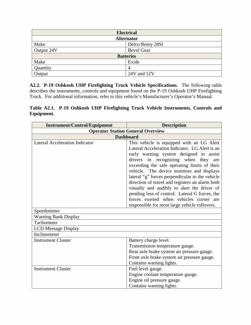
Electrical Alternator
Make Delco Remy 28SI Output 24V Bevel Gear
Batteries Make Exide Quantity 4 Output 24V and 12V
A2.2. P-19 Oshkosh UHP Firefighting Truck Vehicle Specifications. The following table describes the instruments, controls and equipment found on the P-19 Oshkosh UHP Firefighting Truck. For additional information, refer to this vehicle’s Manufacturer’s Operator’s Manual. Table A2.1. P-19 Oshkosh UHP Firefighting Truck Vehicle Instruments, Controls and Equipment.
Instrument/Control/Equipment Description Operator Station General Overview
Dashboard Lateral Acceleration Indicator This vehicle is equipped with an LG Alert
Lateral Acceleration Indicator. LG Alert is an early warning system designed to assist drivers in recognizing when they are exceeding the safe operating limits of their vehicle. The device monitors and displays lateral “g” forces perpendicular to the vehicle direction of travel and registers an alarm both visually and audibly to alert the driver of pending loss of control. Lateral G forces, the forces exerted when vehicles corner are responsible for most large vehicle rollovers.
Speedometer Warning Bank Display Tachometer LCD Message Display Inclinometer Instrument Cluster Battery charge level.
Transmission temperature gauge. Rear axle brake system air pressure gauge. Front axle brake system air pressure gauge. Contains warning lights.
Instrument Cluster Fuel level gauge. Engine coolant temperature gauge. Engine oil pressure gauge. Contains warning lights.

Left Hand Dash Panel Park Brake Knob Master Switch Top Warning Switch Shift Selector Engine Start Switch HVAC Controls Mirror Heat Switch Winterization Switch Driveline Selector Mirror Controls High Idle
Console Switch Panel Foam Switch (Yellow) Water Pump Switch (Blue) Compartment Open Light Working and Ground Light Switches Deluge Switch Bumper Turret Control Joystick
Right Hand Dash Panel Display Screens
Left Display (Firefighter Display) This display shows the operator pump psi, Water lever, Foam level, Dry chemical level. This is NOT a touchscreen display. There are buttons along the bottom that correspond to a function on the display. Across the top of the screen is the warning/fault display. To check the faults, press the red or yellow triangle for more information.
Button 1 Foam percentage selection is not on this model due to the vehicle not having electronic foam injection.
Button 2 Caution alarm silence. Button 3 Clean-up mode (flush and blowdown): The
normal color is black. If display is yellow there is a system clean-up required. Pressing the button will give specific details of what system need cleaned.
Button 4 Fault indicator. It will show up black under normal conditions. It will change to yellow or red depending on fault. Pressing the button again will access the information screen.
Button 5 Screen Dimmer. Button 6 Screen Brightener. Button 7 Menu Button.

Right Display (Camera) The display shows the different cameras equipped on the vehicle. Button 1 Camera 1 Feed. Button 2 Camera 2 Feed. Button 3 Camera 3 Feed. Button 4 Turns screen off. To reactivate, press Buttons
1-3. Button 5 Screen Dimmer. Button 6 Screen Brighter.
Additional Equipment Cameras This vehicle has a backup camera that when
connected properly should automatically show up on the screen when “Reverse” is selected. Forward Looking Infrared (FLIR) Camera: The FLIR camera typically mounts on top of the nozzle. In this position, it rotates vertically with nozzle movement but not horizontally. The wide field of view provided by the FLIR. lens does not usually require horizontal movement. If the object to be viewed is not in the picture, the boom can be rotated left or right. The FLIR and color cameras share the same monitor with a selector switch on the zoom control box.
Structural Screen Button 3 Clean-up mode (flush and blowdown). The
normal color is black. If display is yellow there is a system clean-up required. Pressing the button will give specific details of what system need cleaned.
Button 5 Screen Dimmer. Button 6 Screen Brightener.
Structural Panel Switch 1 Turns structural panel on Switch 2 Water tank shut-off (used for drafting) Switch 3 Water (blue) only pump activation Switch 4 Foam (yellow) activation. This will engage the
water pump as well. Switch 5 RPM/PSI mode selection Switch 6 Increase/Decrease rpm or psi (throttle speed) Switch 8 Idle/Preset switch 150 psi, 1500 rpm Pump Primer Foam percent selection switch for the entire truck system. Tank Drain.

Tank fill from draft. Pull handle out to fill Emergency engine shutdown. Red button Pressure relief valve. Foam multi-metering valve handle This handle can be used to control the foam
percentage in the two 2 ½ inch discharges.

Attachment 3
P-19 OSHKOSH UHP FIREFIGHTING TRUCK INSPECTION GUIDE
GENERAL STEP 1. VEHICLE OVERVIEW Paperwork
• AF Form 1800 • Discrepancy Correction Complete (VM Annotation)
Vehicle Approach • Damage • Vehicle Leaning? • Fresh Leakage of Fluids • Hazards Surrounding Vehicle
INTERNAL STEP 2. ENGINE COMPARTMENT Leaks/Hoses/Electrical Wiring Insulation Oil Level Coolant Level Power Steering Fluid Windshield Washer Fluid Battery Fluid Level, Connections & Tiedowns Automatic Transmission Fluid Level Engine Compartment Belts STEP 3. ENGINE START/CAB CHECK (LEFT/FRONT/RIGHT) Safe Start Gauges
• Oil Pressure Gauge • Air Pressure Gauge • Temperature Gauge (Coolant/Engine Oil) • Ammeter/Voltmeter
Siren Communications System Windows Seat Adjustment Mirrors & Windshield Wipers/Washers Removable Firefighting Equipment (missing/damaged)
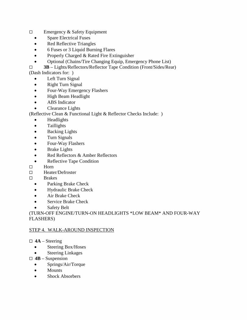
Emergency & Safety Equipment • Spare Electrical Fuses • Red Reflective Triangles • 6 Fuses or 3 Liquid Burning Flares • Properly Charged & Rated Fire Extinguisher • Optional (Chains/Tire Changing Equip, Emergency Phone List)
3B – Lights/Reflectors/Reflector Tape Condition (Front/Sides/Rear) (Dash Indicators for: )
• Left Turn Signal • Right Turn Signal • Four-Way Emergency Flashers • High Beam Headlight • ABS Indicator • Clearance Lights
(Reflective Clean & Functional Light & Reflector Checks Include: ) • Headlights • Taillights • Backing Lights • Turn Signals • Four-Way Flashers • Brake Lights • Red Reflectors & Amber Reflectors • Reflective Tape Condition
Horn Heater/Defroster Brakes
• Parking Brake Check • Hydraulic Brake Check • Air Brake Check • Service Brake Check • Safety Belt
(TURN-OFF ENGINE/TURN-ON HEADLIGHTS *LOW BEAM* AND FOUR-WAY FLASHERS) STEP 4. WALK-AROUND INSPECTION 4A – Steering
• Steering Box/Hoses • Steering Linkages
4B – Suspension • Springs/Air/Torque • Mounts • Shock Absorbers

4C – Brakes • Slack Adjustors & Pushrods • Brake Chambers • Brake Hoses/Lines • Drum Brake • Brake Linings
4D – Wheels • Rims • Tires • Hub Oil Seals/Axle Seals • Lug Nuts • Spacers & Budd Spacing
4D – Body Panels
LEFT SIDE/DRIVER SIDE OF P-19 OSHKOSH UHP FIREFIGHTING TRUCK 4E – Doors 4E – Mirrors 4E – Fuel Tank
RIGHTSIDE/PASSENGER SIDE OF P-19 OSHKOSH UHP FIREFIGHTING TRUCK 4E – Doors 4E – Mirrors 4E – Fuel Tank 4E – Body Panels UNDER VEHICLE 4F – Drive Shaft 4F – Exhaust 4F – Frame FIREFIGHTING EQUIPMENT, WATER & FOAM PIPING 4G – Piping/Drain Valves (Underside) 4G – Foam Tank Gate Valve 4G – Foam Tank Overflow Hose Clamp 4G – Firefighting Equipment 4G – Dispense Systems Gauge Readings 4G – Hose Reel 4G – Hose REAR OF P-19 OSHKOSH UHP FIREFIGHTING TRUCK 4H – Doors

Figure A3.1. P-19 Oshkosh UHP Firefighting Truck Inspection Guide.

Attachment 4
PERFORMANCE TEST
A4.1. Desired Learning Outcome.
A4.1.1. Understand the safety precautions to be followed pre, during, and post operation of the P-19 Oshkosh UHP Firefighting Truck. A4.1.2. Understand the purpose of the P-19 Oshkosh UHP Firefighting Truck and its role in the mission. A4.1.3. Know the proper operator maintenance procedures of the P-19 Oshkosh UHP Firefighting Truck IAW applicable technical orders and use of AF Form 1800. A4.1.4. Safely and proficiently operate the P-19 Oshkosh UHP Firefighting Truck.
A4.2. Instructions. Before beginning the performance test, the trainer will brief the trainee on the scenario he/she will need to accomplish. He/she will be given additional directions and instructions as needed to proceed through the scenario. A4.3. Scoring.
A4.3.1. The trainer examiner will be scoring the trainee on P-19 Oshkosh UHP Firefighting Truck operations and also the general safe driving practices. The examiner will give directions and instructions to the trainee in sufficient time for o execute a driving maneuver. He/she will not be asked to drive in an unsafe manner. A4.3.2. The examiner will be making various marks on the performance test checklist. This does not necessarily mean the trainee has done anything wrong. It is in the best interest to concentrate on the operation of the P-19 Oshkosh UHP Firefighting Truck. The trainer will explain the test results at the conclusion of the performance test. A4.3.3. Tasks being graded are listed on the following page; the trainee will be required to successfully pass all items. A4.3.4. The instructor will stop the test at any time safe P-19 Oshkosh UHP Firefighting Truck operations are not being followed or as deemed necessary for safety concerns.
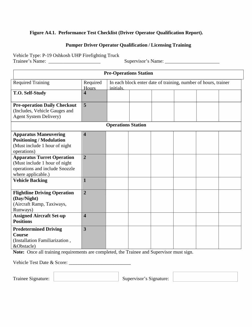
Figure A4.1. Performance Test Checklist (Driver Operator Qualification Report).
Pumper Driver Operator Qualification / Licensing Training
Vehicle Type: P-19 Oshkosh UHP Firefighting Truck Trainee’s Name: _____________________ Supervisor’s Name: ______________________
Apparatus Maneuvering Positioning / Modulation (Must include 1 hour of night operations)
4
Apparatus Turret Operation (Must include 1 hour of night operations and include Snozzle where applicable.)
2
Vehicle Backing
1
Flightline Driving Operation (Day/Night) (Aircraft Ramp, Taxiways, Runways)
2
Assigned Aircraft Set-up Positions
4
Predetermined Driving Course (Installation Familiarization , &Obstacle)
3
Note: Once all training requirements are completed, the Trainee and Supervisor must sign.
Vehicle Test Date & Score: _________________________
Trainee Signature: Supervisor’s Signature:
T.O. Self-Study 4
Pre-operation Daily Checkout (Includes, Vehicle Gauges and Agent System Delivery)
5
Pre-Operations Station
Required Training Required Hours
In each block enter date of training, number of hours, trainer initials.
Operations Station

Trainee’s Name: ___________________ Evaluators Name: _________________________
Driver Operator Certification Report Candidate must pass all evaluated areas for licensing
Note: Refer to CDC 10023W Driver/Operator - Pumper Performance Test for detailed description of above task.
Driver Operator Remedial Training
If a candidate fails a certification task, provide an explanation of what remedial training was accomplished to correct deficiency.
Date Trainer Trainee Initials
Task(s) Failed
What training was done to correct the deficiency:
I certify that I have tested the above individual and they are proficient to drive and operate the vehicle. Evaluator Signature:
Go No-Go Evaluated Area Successfully complete all pre-operations daily checks
(Inside Cab, Outside, Engine Compartment, Fire Pump, Water Tank, Foam Tank/System, Tools and Equipment )
Successfully identify the major components of the agent delivery system Successfully identify and explain potential performance problems based upon
apparatus gauge readings Successfully explain the basic dimensions and turning radius of the apparatus Successfully pump a supply line to an ARFF apparatus Successfully demonstrate maneuvering/positioning of apparatus IAW Aircraft pre-incident
plans for all assigned aircraft (Wind direction, terrain, type of aircraft, cargo, armament, fire location & other ARFF vehicle positions shall be considered)
Successfully demonstrate apparatus modulation (pump & roll) while discharging agent on initial approach to an aircraft related fire (Continuous / uninterrupted discharge of agent once apparatus is in range of intended target )
Successfully demonstrate operation of the Snozzle (Where applicable ) Successfully complete an obstacle driving course
( Alley Dock, Serpentine, 180 degree Turnaround, Diminished Clearance, Lane Change, Straight Line )
Successfully demonstrate ability to operate apparatus under off road conditions ( loose soil/sand, wet soil/sand, reduced sight, undercarriage obstruction )

Attachment 5
OPERATION & TROUBLESHOOTING GUIDE FOR THE AIR FORCE IDLE REDUCTION TECHNOLOGY (IRT) SYSTEM
A5.1. Idle Reduction Technology (IRT) Overview. IRT describes the technology and practices that minimize the amount of time operators idle their engines. Avoiding idling time has a multitude of benefits including: savings in fuel and maintenance costs, extending vehicle life, and reducing damaging emissions. This truck is equipped with this technology. A5.2. Enabling IRT. There is only one way to enable IRT on this unit, the following conditions have to be met for 2 minutes for the multiplexing system to request the generator to automatically start. If any of the conditions change from the state mentioned the timer will reset to zero and will restart once they are met again:
A5.2.1. Truck engine running. A5.2.2. Transmission is in neutral. A5.2.3. Park brake is applied. A5.2.4. Pump not engaged. A5.2.5. Generator is not running. A5.2.6. IRT disable switch off (down position). A5.2.7. Generator DC control breaker switch is ON.
A5.3. IRT Mode. No more than 5 seconds after the generator auto starts (2 min of idling) the truck engine will automatically shut OFF. Approximately 5 seconds after the engine automatically shuts OFF the converters will switch the truck over to generator power at this point the truck is considered to be IRT mode.
A5.3.1. In IRT mode the following 120v items WILL be powered up:
A5.3.1.1. Block heaters.
A5.3.1.2. Climate control system (Penguin).
A5.3.1.3. Oil heaters.
A5.3.1.4. Pan heaters.
A5.3.1.5. Battery heater.

A5.3.1.6. Battery chargers.
A5.3.1.7. IRT converters.
A5.3.2. In IRT mode the following 12V items WILL be powered:
A5.3.2.1. Radios. A5.3.2.2. DOT lighting. A5.3.2.3. NFPA required emergency lights. A5.3.2.4. Step lights. A5.3.2.5. Work lights. A5.3.2.6. Compartment lights.
A5.3.3. In IRT mode the following 120V items will NOT be powered:
A5.3.3.1. Lights. A5.3.3.2. Reels. A5.3.3.3. Receptacles.
A5.3.4. The truck is considered to be in Generator mode when converters are not enabled and the generator was manually started with the truck running this mode the gen will need to have manual preheat applied via the switch in the overhead driver side before the gen is started. Gen mode the following 120V items WILL be powered:
A5.3.4.1. Reel. A5.3.4.2. Receptacles.
A5.3.5. To switch from IRT mode to normal operation mode:
A5.3.5.1. Bring Ignition switch one click down to Master power. A5.3.5.2. Wait for generator to turn-off. A5.3.5.3. Wait 2 seconds. A5.3.5.4. Power back up and start truck.

A5.4. IRT Operating Indicator. Light found in overhead driver side.
A5.4.1. The IRT operating indicator will flash 120 fpm when disable switch is in “ON” position indicating IRT CANNOT be enabled. Not flashing if service switch is OFF, steady burn indicates IRT is operating a custom flash pattern when the DC control breaker found on the generator is in the OFF position. A5.4.2. If the generator cranks but does not run within approx. 10 sec of the request to start, cycle power to truck and with engine not running verify generator functionality manually via the manual start button in the overhead or with the switch found on the generator itself. A5.4.3. If generator is running but does not switch over, verify converter breakers and solenoids are working properly, converters not switching over will sound the reverse alarm.

Figure A5.1. Troubleshooting IRT Problems.
Troubleshooting IRT Problems Symptom Possible Solution
Generator does not automatically start after 2 minutes of truck idle.
Verify that: Truck engine is running; Transmission is in neutral; Park Brake is applied; Pump not engaged; Generator is not running; IRT disable switch is off (down position); Switch on generator is in the ON position. Manually change state to each command mentioned above. Cycle power to truck. Contact local dealer for support.
Generator running but converters do not power up.
Verify that the generator started automatically after truck has been idling for 2 min. Verify that the coil side of relay has 12 volts to ground. If not, contact local dealer for support. Verify source side of relay has 120 volts to ground. If not, press fault reset button on generator. Verify load side of relay has 120 volts to ground. If not, replace relay.
Generator running and convertors are ON, does not switch from battery power to generator power.
Verify source side of solenoid has 12 volts to ground. If not, verify fuse, replace if necessary. Verify load side of solenoid has 12 volts to ground. If, not replace solenoid. Verify trigger wire to solenoid has 12 volts to ground. If not, verify connection of wire.
Truck 12 volt A/C not working when IRT turned off.
Turn truck OFF for 2 seconds. Contact local dealer for support.
Reverse warning when generator auto start and engine auto OFF.
Converters did not power up or solenoids did not transfer truck to generator power. Cycle power to truck.
Verify symptom "Generator running but converters do not power up" Verify load side of fuse has 12 volts to ground. If not, replace fuse. Contact local dealer for support.

Attachment 6
SEVEN-STEP INSPECTION PROCESS Figure A6.1. Seven-Step Inspection Process.
Seven-Step Inspection Process Step Procedure 1. Vehicle Overview • Review the AF Form 1800.
o Ensure any discrepancy has been corrected.
o Vehicle Management annotated the discrepancy was completed.
o Approaching the vehicle. Damage or vehicle leaning to one
side. Fresh leakage of fluids. Hazards around vehicle.
2. Check Engine Compartment • Note: Check that the parking brakes are on and/or wheels chocked. The operator may have to raise the hood, tilt the cab (secure loose things so they don't fall and break something), or open the engine compartment door.
• Check the following: o Engine oil level. o Coolant level in radiator; condition of
hoses. o Power steering fluid level; hose
condition (if so equipped). o Windshield washer fluid level. o Battery fluid level, connections and
tie-downs (battery may be located elsewhere).
o Automatic transmission fluid level (may require engine to be running).

o Check belts for tightness and excessive wear (alternator, water pump, air compressor)--learn how much "give" the belts should have when adjusted right.
o Leaks in the engine compartment (fuel, coolant, oil, power steering fluid, hydraulic fluid, battery fluid). Cracked, worn electrical wiring insulation.
3. Start Engine and Inspect Inside the Cab (Get in and Start Engine)
• Make sure parking brake is on. • Put gearshift in neutral (or park if
automatic). Start engine; listen for unusual noises.
• If equipped, check the Anti-lock Braking System (ABS) indicator lights. Light on dash should come on and then turn-off. If it stays on the ABS is not working properly.
• Note: For trailers only, if the yellow light on the left rear of the trailer stays on, the ABS is not working properly.
• Look at the gauges. o Oil pressure. Should come up to
normal within seconds after engine is started.
o Air pressure. Pressure should build from 50 to 90 psi within 3 minutes. Build air pressure to governor cut-out (usually around 120 – 140 psi. Know the vehicle’s requirements.
o Ammeter and/or voltmeter. Should be in normal range(s).
o Coolant temperature. Should begin gradual rise to normal operating range.
o Engine oil temperature. Should begin gradual rise to normal operating range.

o Warning lights and buzzers. Oil, coolant, charging circuit warning, and antilock brake system lights should go out right away.
o Check Condition of Controls. Check all of the following for looseness, sticking, damage, or improper setting:
Steering wheel. Clutch. Accelerator (gas pedal). Brake controls. Foot brake. Trailer brake (if vehicle has one). Parking brake. Retarder controls (if vehicle has
them). Transmission controls. Interaxle differential lock (if vehicle
has one). Horn(s). Windshield wiper/washer. Lights. Headlights. Dimmer switch. Turn signal. Four-way flashers. Parking – clearance – identification –
marker switch (switches). • Check mirrors and windshield. o Inspect mirrors and windshield for
cracks, dirt, illegal stickers, or other obstructions to seeing clearly. Clean and adjust as necessary.
• Check emergency equipment. o Check for safety equipment: Spare electrical fuses (unless vehicle
has circuit breakers). Three red reflective triangles, 6 fuses
or 3 liquid burning flares.

Properly charged and rated fire extinguisher. Check for optional items such as:
Chains (where winter conditions require).
Tire changing equipment. List of emergency phone numbers
Accident reporting kit (packet). o Check safety belt. Check that the
safety belt is securely mounted, adjusts; latches properly and is not ripped or frayed.
4. Turn-off Engine • Make sure the parking brake is set, turn-off the engine, and take the key with.
• Turn-on headlights (low beams) and four-way emergency flashers, and get out of the vehicle.
5. Do Walk-Around Inspection • General. o Go to front of vehicle and check that
low beams are on and both of the four-way flashers are working.
o Push dimmer switch and check that high beams work.
o Turn-off headlights and four-way emergency flashers.
o Turn-on parking, clearance, side-marker, and identification lights.
o Turn-on right turn signal, and start walk-around inspection.
o Walk around and inspect. Clean all lights, reflectors, and glass
as while doing the walk-around inspection.
• Left front side. o Driver's door glass should be clean. o Door latches or locks should work
properly. • Left front wheel.

o Condition of wheel and rim--missing, bent, broken studs, clamps, lugs, or any signs of misalignment.
o Condition of tires--properly inflated, valve stem and cap OK, no serious cuts, bulges, or tread wear.
o Use wrench to test rust-streaked lug nuts, indicating looseness.
o Hub oil level OK, no leaks. Left front suspension.
o Condition of spring, spring hangers, shackles,
o U-bolts. o Shock absorber condition. • Left front brake. o Condition of brake drum or disc. o Condition of hoses. • Front. o Condition of front axle. Condition of
steering system. o No loose, worn, bent, damaged or
missing parts. o Must grab steering mechanism to test
for looseness. o Condition of windshield. o Check for damage and clean if dirty. o Check windshield wiper arms for
proper spring tension. o Check wiper blades for damage,
"stiff" rubber, and securement. o Lights and reflectors. o Parking, clearance, and identification
lights clean, operating, and proper color (amber at front).
o Reflectors clean and proper color (amber at front).
o Right front turn signal light clean, operating, and proper color (amber or white on signals facing forward).
• Right side
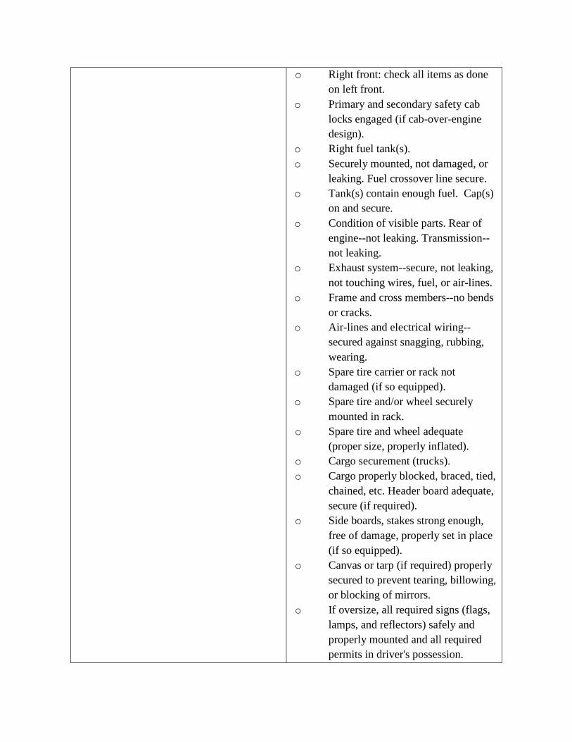
o Right front: check all items as done on left front.
o Primary and secondary safety cab locks engaged (if cab-over-engine design).
o Right fuel tank(s). o Securely mounted, not damaged, or
leaking. Fuel crossover line secure. o Tank(s) contain enough fuel. Cap(s)
on and secure. o Condition of visible parts. Rear of
engine--not leaking. Transmission--not leaking.
o Exhaust system--secure, not leaking, not touching wires, fuel, or air-lines.
o Frame and cross members--no bends or cracks.
o Air-lines and electrical wiring--secured against snagging, rubbing, wearing.
o Spare tire carrier or rack not damaged (if so equipped).
o Spare tire and/or wheel securely mounted in rack.
o Spare tire and wheel adequate (proper size, properly inflated).
o Cargo securement (trucks). o Cargo properly blocked, braced, tied,
chained, etc. Header board adequate, secure (if required).
o Side boards, stakes strong enough, free of damage, properly set in place (if so equipped).
o Canvas or tarp (if required) properly secured to prevent tearing, billowing, or blocking of mirrors.
o If oversize, all required signs (flags, lamps, and reflectors) safely and properly mounted and all required permits in driver's possession.

o Curbside cargo compartment doors in good condition, securely closed, latched/locked and required security seals in place.
• Right rear. o Condition of wheels and rims--no
missing, bent, or broken spacers, studs, clamps, or lugs.
o Condition of tires--properly inflated, valve stems and caps OK, no serious cuts, bulges, tread wear, tires not rubbing each other, and nothing stuck between them.
o Tires same type, e.g., not mixed radial and bias types.
o Tires evenly matched (same sizes). Wheel bearing/seals not leaking.
o Suspension. o Condition of spring(s), spring
hangers, shackles, and u-bolts. o Axle secure. o Powered axle(s) not leaking lube
(gear oil). Condition of torque rod arms, bushings.
o Condition of shock absorber(s). o If retractable axle equipped, check
condition of lift mechanism. If air powered, check for leaks.
o Condition of air ride components. o Brakes. o Brake adjustment. o Condition of brake drum(s) or discs. o Condition of hoses--look for any
wear due to rubbing. o Lights and reflectors. o Side-marker lights clean, operating,
and proper color (red at rear, others amber).

o Side-marker reflectors clean and proper color (red at rear, others amber).
• Rear. o Lights and reflectors. o Rear clearance and identification
lights clean, operating, and proper color (red at rear).
o Reflectors clean and proper color (red at rear).
o Taillights clean, operating, and proper color (red at rear).
o Right rear turn signal operating, and proper color (red, yellow, or amber at rear).
o License plate(s) present, clean, and secured.
o Splash guards present, not damaged, properly fastened, not dragging on ground, or rubbing tires.
o Cargo secure (trucks). o Cargo properly blocked, braced, tied,
chained, etc. Tailboards up and properly secured.
o End gates free of damage, properly secured in stake sockets.
o Canvas or tarp (if required) properly secured to prevent tearing, billowing, or blocking of either the rearview mirrors or rear lights.
o If over-length, or over-width, make sure all signs and/or additional lights/flags are safely and properly mounted and all required permits are in driver's possession.
o Rear doors securely closed, latched/locked.
• Left side. o Check all items as done on right side,
plus:
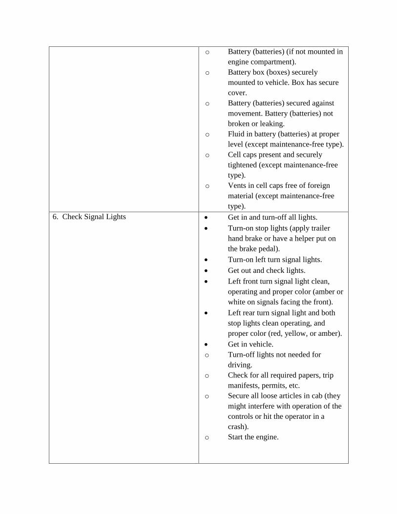
o Battery (batteries) (if not mounted in engine compartment).
o Battery box (boxes) securely mounted to vehicle. Box has secure cover.
o Battery (batteries) secured against movement. Battery (batteries) not broken or leaking.
o Fluid in battery (batteries) at proper level (except maintenance-free type).
o Cell caps present and securely tightened (except maintenance-free type).
o Vents in cell caps free of foreign material (except maintenance-free type).
6. Check Signal Lights • Get in and turn-off all lights. • Turn-on stop lights (apply trailer
hand brake or have a helper put on the brake pedal).
• Turn-on left turn signal lights. • Get out and check lights. • Left front turn signal light clean,
operating and proper color (amber or white on signals facing the front).
• Left rear turn signal light and both stop lights clean operating, and proper color (red, yellow, or amber).
• Get in vehicle. o Turn-off lights not needed for
driving. o Check for all required papers, trip
manifests, permits, etc. o Secure all loose articles in cab (they
might interfere with operation of the controls or hit the operator in a crash).
o Start the engine.

7. Start the Engine and Check Test for Hydraulic Leaks
• Test for hydraulic leaks. o If the vehicle has hydraulic brakes,
pump the brake pedal three times. o Then apply firm pressure to the pedal
and hold for five seconds. o The pedal should not move. If it
does, there may be a leak or other problem.
• Brake system. • Test parking brake. o Fasten safety belt. o Set parking brake (power unit only).
Release trailer parking brake (if applicable). Place vehicle into a low gear.
o Gently pull forward against parking brake to make sure the parking brake holds.
o Repeat the same steps for the trailer with trailer parking brake set and power unit parking brakes released (if applicable).
o If it doesn't hold vehicle, it is faulty; get it fixed.
• Test service brake stopping action. o Go about 5 miles per hour. o Push brake pedal firmly. o "Pulling" to one side or the other can
mean brake trouble. o Any unusual brake pedal "feel" or
delayed stopping action can mean trouble.
o If the trainee finds anything unsafe during the Vehicle inspection, get it fixed. Federal and state laws forbid operating an unsafe vehicle.
• Check vehicle operation regularly: o Instruments. o Air pressure gauge (if the vehicle has
air brakes). Temperature gauges.

o Pressure gauges. Ammeter/voltmeter.
o Mirrors. o Tires. o Cargo, cargo covers. Lights, etc. o If the trainee sees, hears, smells, or
feels anything that might mean trouble, he/she should check it out.
• Safety inspection. o Drivers of trucks and truck tractors
when transporting cargo must inspect the securement of the cargo within the first 50 miles of a trip and every 150 miles or every 3 hours (whichever comes first) after.
• Document any discrepancy on AF Form 1800. Sign-off AF Form 1800 to signify accomplishment of inspection.

Figure A6.2. Additional Steps for Inspecting Air Brakes System.
Additional Steps for Inspecting Air Brakes Step Procedure
2. Engine Compartment Checks • Check air compressor drive belt condition and tightness (if compressor is belt driven).
5. Walk-Around Inspecting • Check manual slack adjusters on S-cam brakes. Note: Vehicles with automatic slack adjustors still must be checked.
o Park on level ground and chock the wheels. o Release the parking brakes so the operator can
move the slack adjusters. o Use gloves and pull hard on each slack
adjuster that it can be reached. o Check slack adjuster, more than 1-inch
indicates adjustments required (vehicles with too much brake slack can be very hard to stop). Adjust it or have it adjusted.
• Check brake drums (or discs), linings, and hoses.
7. Final Air Brake Check • Test low pressure warning signal. o Shut the engine off when the vehicle has
enough air pressure so that the low pressure warning signal is not on.
o Turn the electrical power on. o Step on and off the brake pedal to reduce air
tank pressure. o Low air pressure warning signal should come
on before the pressure drops to less than 60 psi in the air tank with lowest pressure.
• Check that the spring brakes come on automatically.
o Chock the wheels. o Release the parking brakes when enough air
pressure is built up. o Shut the engine off. o Step on and off the brake pedal to reduce the
air tank pressure. o "Parking brake" knob should pop out when
the air pressure falls to the manufacturer's specification.
• Check rate of air pressure buildup o Refer to manufacturer’s recommendation for
average buildup time.

o If not within recommended time, the air pressure may drop too low during driving operations.
• Test air leakage rate. o With a fully-charged air system (typically 125
psi). o Turn-off the engine. o Release the service brake and time the air
pressure drop. o The loss rate should be less than 2 psi in one
minute for single vehicles. o Not less than 3 psi in 1 minute for
combination vehicles. • Then apply 90 psi or more with the brake
pedal. o After the initial pressure drop, if the air
pressure falls more than 3 psi in 1 minute for single vehicles.
o Not more than 4 psi for combination vehicles. • Check air compressor governor cut-in and
cut-out pressures. o Air compressor should start at about 100 psi
and stop at about 125 psi. o Run the engine at a fast idle. o Air governor should cut-out the air
compressor at about the manufacturer's specified pressure.
o Engine idling, step on and off brake to reduce air tank pressure.
o Compressor should cut-in at manufacturer's specified cut-in pressure.
o Test parking brake: Stop the vehicle; put the parking brake on; gently pull against it in low gear to determine if parking brake will hold.
Test service brakes. Wait for normal air pressure. • Release the parking brake. • Move the vehicle forward slowly (about 5
mph). • Apply the brakes firmly using the brake pedal. • Note any vehicle "pulling" to one side,
unusual feel, or delayed stopping action.