oxy fuel welding basic setup & use. typical torch system n oxygen cylinder n acetylene cylinder...
TRANSCRIPT
Oxy Fuel WeldingBasic Setup & Use
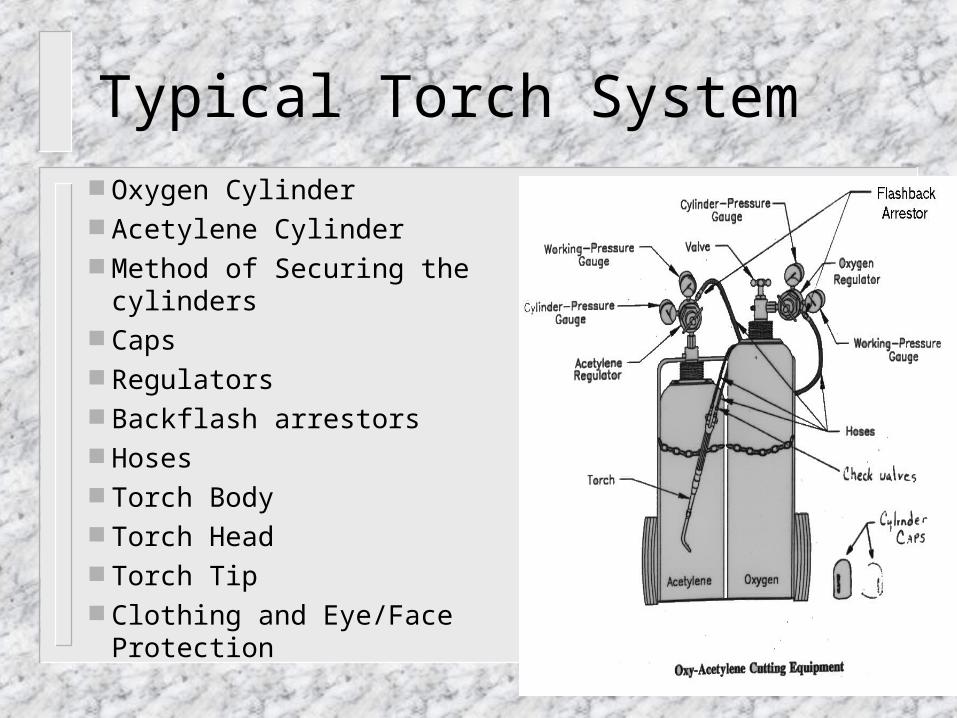
Typical Torch System Oxygen Cylinder Acetylene Cylinder Method of Securing the cylinders Caps Regulators Backflash arrestors Hoses Torch Body Torch Head Torch Tip Clothing and Eye/Face Protection
Oxygen Cylinders
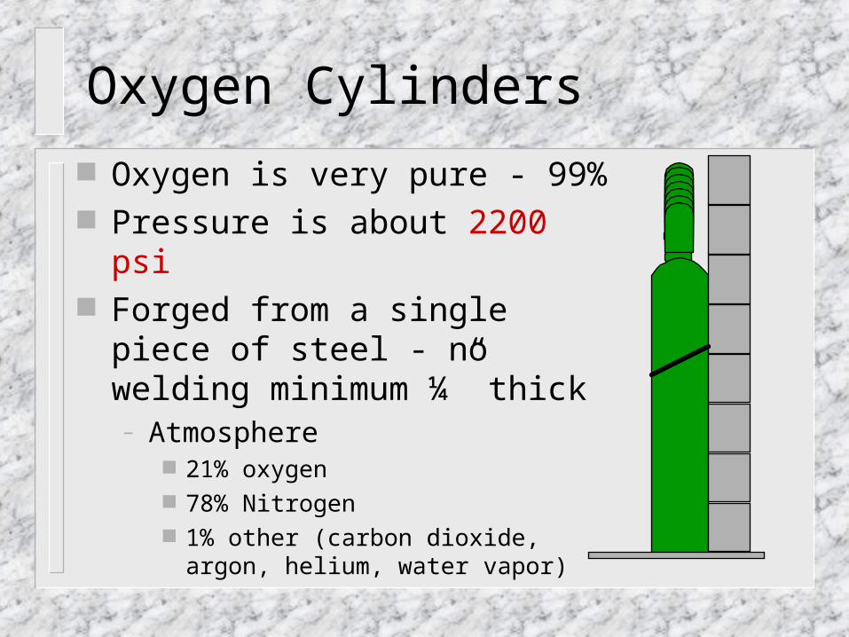
Oxygen is very pure - 99% Pressure is about 2200 psi Forged from a single piece of steel -
no welding minimum ¼” thick– Atmosphere
21% oxygen 78% Nitrogen 1% other (carbon dioxide, argon, helium,
water vapor)
Oxygen Cylinder Safety
Open valve all the way. Transport with safety cap on Tanks should always be safety chained Torpedo
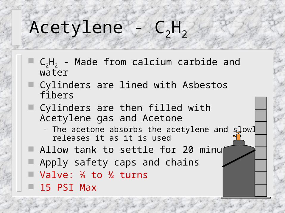
C2H2 - Made from calcium carbide and water Cylinders are lined with Asbestos fibers Cylinders are then filled with Acetylene gas and Acetone
– The acetone absorbs the acetylene and slowly releases it as it is used
Allow tank to settle for 20 minutes Apply safety caps and chains Valve: ¼ to ½ turns 15 PSI Max
Acetylene - C2H2
Regulators
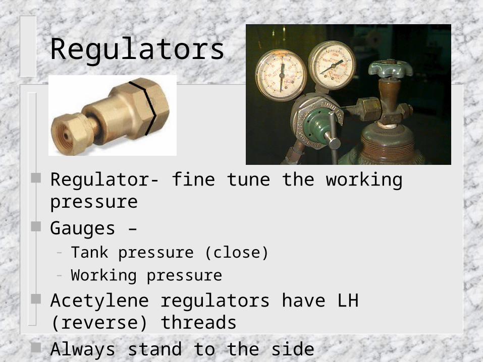
Regulator- fine tune the working pressure Gauges –
– Tank pressure (close) – Working pressure
Acetylene regulators have LH (reverse) threads Always stand to the side Crack valve during tank replacement
Backflash Arrestor
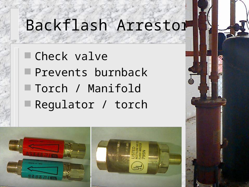
Check valve Prevents burnback Torch / Manifold Regulator / torch
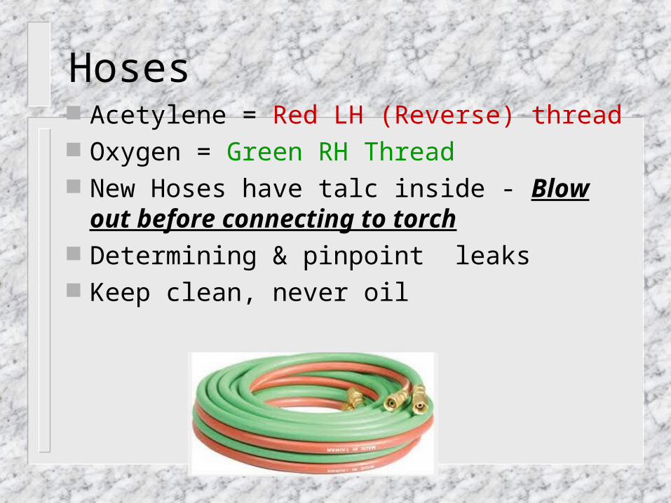
Hoses Acetylene = Red LH (Reverse) thread Oxygen = Green RH Thread New Hoses have talc inside - Blow out
before connecting to torch Determining & pinpoint leaks Keep clean, never oil
Back Flash
Reverse flow of combusting gas into cylinder Typically caused by improper working
pressures or torch distance Crackle, stub, whistle IMIDIATELY kill main acetylene valve\ Tank could explode Video
Torch Body
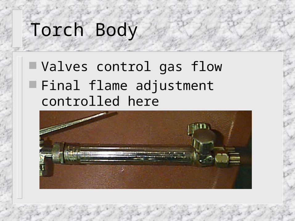
Valves control gas flow Final flame adjustment controlled here
Setup Procedures
Confirm regulator screw positions (out) Stand to the side of regulators Open tanks one at a time
– (Acetylene: 1/4 turn, Oxygen: Full)
Set acetylene working pressure– Welding: 3-5 psi, Cutting: 5-7 psi
Set Oxygen– Welding: 3-5 psi, Cutting: 20-23 psi

Setup Video (5 min)
http://www.youtube.com/watch?v=EQjd3qBpWVE
Lighting Procedure
Crack acetylene valve Light with friction lighter
– (do not light with anything else!!!) Adjust acetylene (little smoke) Slowly adjust oxygen for neutral flame
– Note: cutting pressure is set with trigger pulled Flame temp is about 5500°F Steel melts at 2800°F
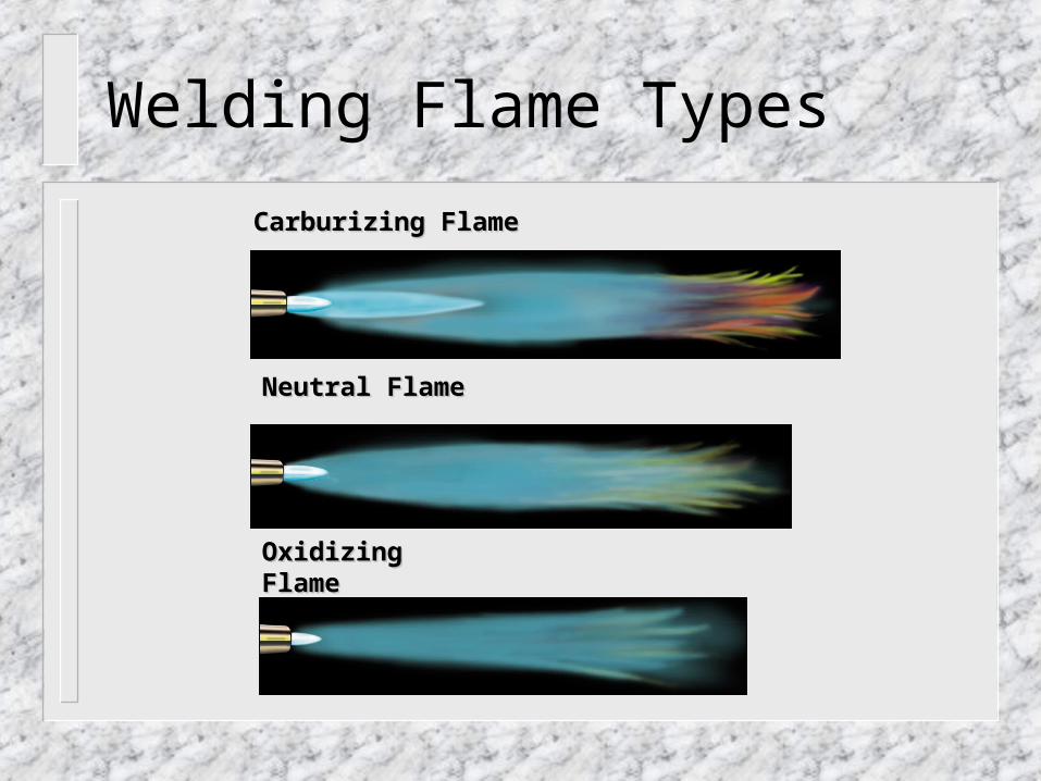
Carburizing FlameCarburizing Flame
Neutral Flame Neutral Flame
Oxidizing FlameOxidizing Flame
Welding Flame Types
Shut Down Procedure
Turn off acetylene torch valve Turn off oxygen torch valve Shut down tanks Bleed lines Shut down regulators
Oxy-Acetylene Welding (no filler)
Hold blue cone about 1/16-1/8” from metal at a 15-45° angle
Move tip in small circles until a molten puddle is formed
Slowly push the puddle across the metal
Oxy-Acetylene Welding (With Filler R-45)
Filler material helps fill the joint Added to puddle on backstroke Heat metal until puddle is formed Position 20* angle from base metal 90* torch relationship Metal will melt off of filler rod and be drawn into
puddle Slowly push the puddle across the work piece
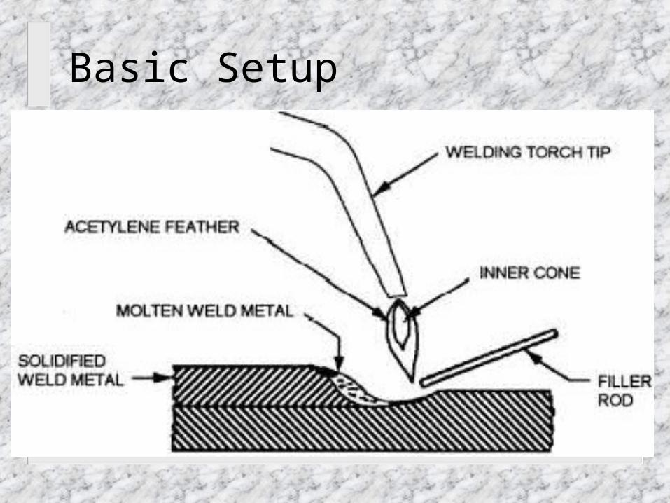
Basic Setup
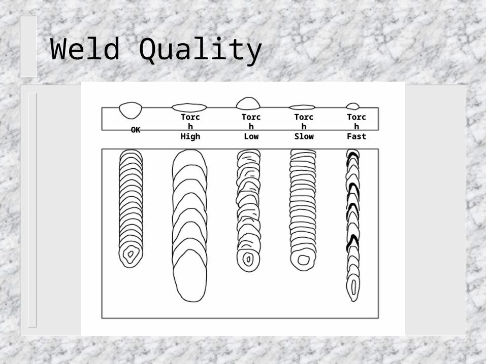
OKOK
Torch Torch HighHigh
Torch Torch LowLow
Torch Torch SlowSlow
Torch Torch FastFast
Weld Quality
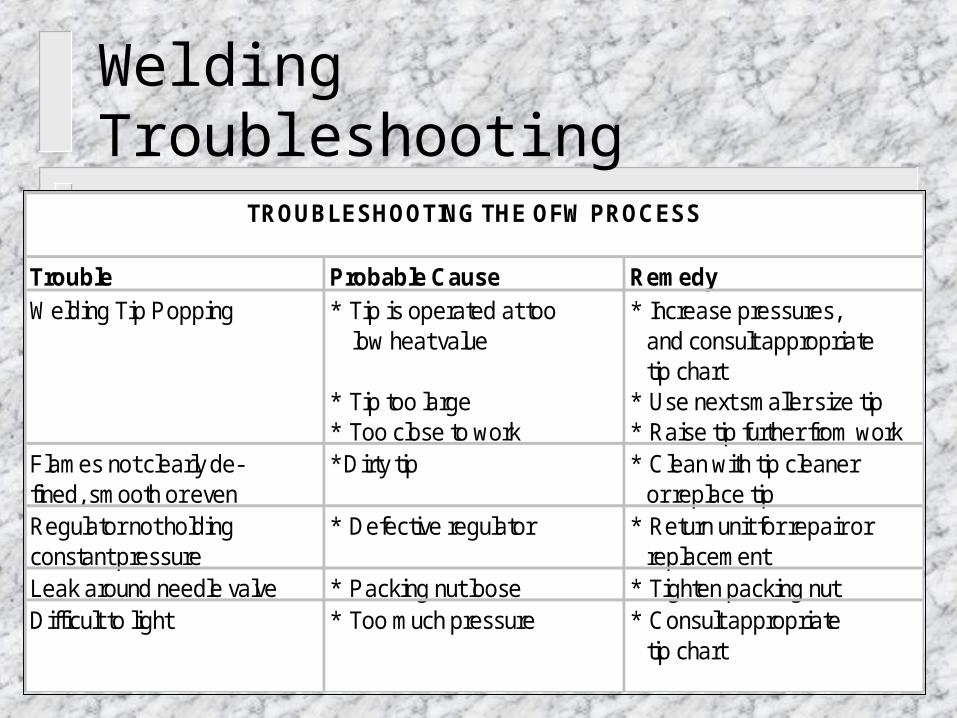
TROUBLESHOOTING THE OFW PROCESS
Trouble Probable Cause RemedyWelding Tip Popping * Tip is operated at too * Increase pressures,
low heat value and consult appropriate tip chart
* Tip too large * Use next smaller size tip* Too close to work * Raise tip further from work
Flames not clearly de- * Dirty tip * Clean with tip cleanerfined, smooth or even or replace tipRegulator not holding * Defective regulator * Return unit for repair orconstant pressure replacementLeak around needle valve * Packing nut loose * Tighten packing nutDifficult to light * Too much pressure * Consult appropriate
tip chart
Welding Troubleshooting
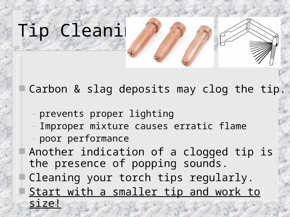
Tip Cleaning
Carbon & slag deposits may clog the tip. – prevents proper lighting– Improper mixture causes erratic flame – poor performance
Another indication of a clogged tip is the presence of popping sounds.
Cleaning your torch tips regularly. Start with a smaller tip and work to size!
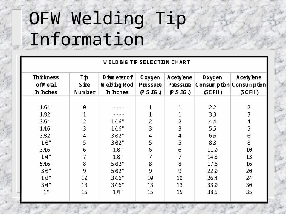
WELDING TIP SELECTION CHART
Thickness Tip Diameter of Oxygen Acetylene Oxygen Acetyleneof Metal Size Welding Rod Pressure Pressure Consumption Consumption
In Inches Number In Inches (P.S.I.G.) (P.S.I.G.) (SCFH) (SCFH)
1/64" 0 - - - - 1 1 2.2 21/32" 1 - - - - 1 1 3.3 33/64" 2 1/16" 2 2 4.4 41/16" 3 1/16" 3 3 5.5 53/32" 4 3/32" 4 4 6.6 61/8" 5 3/32" 5 5 8.8 83/16" 6 1/8" 6 6 11.0 101/4" 7 1/8" 7 7 14.3 135/16" 8 5/32" 8 8 17.6 163/8" 9 5/32" 9 9 22.0 201/2" 10 3/16" 10 10 26.4 243/4" 13 3/16" 13 13 33.0 301" 15 1/4" 15 15 38.5 35
OFW Welding Tip Information

BRAZING TIP SELECTION CHART
Thickness Tip Diameter of Oxygen Acetylene Oxygen Acetyleneof Metal Size Brazing Rod Pressure Pressure Consumption Consumption
In Inches Number In Inches (P.S.I.G.) (P.S.I.G.) (SCFH) (SCFH)
1/64" 0 ---- 1 1 2.2 21/32" 1 ---- 1 1 3.3 33/64" 2 1/16" 2 2 4.4 41/16" 3 1/16" 3 3 5.5 53/32" 4 3/32" 4 4 6.6 61/8" 5 3/32" 5 5 8.8 83/16" 6 1/8" 6 6 11.0 101/4" 7 1/8" 7 7 14.3 135/16" 8 5/32" 8 8 17.6 163/8" 9 5/32" 9 9 22.0 201/2" 10 3/16" 10 10 26.4 24
OFB Brazing Tip Information
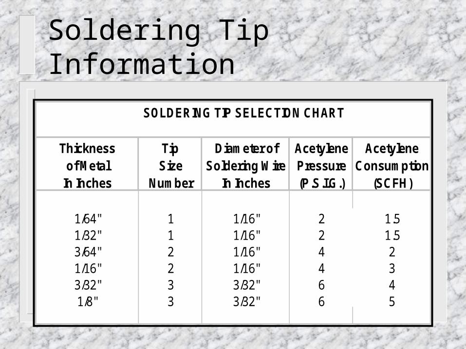
SOLDERING TIP SELECTION CHART
Thickness Tip Diameter of Acetylene Acetyleneof Metal Size Soldering Wire Pressure Consumption
In Inches Number In Inches (P.S.I.G.) (SCFH)
1/64" 1 1/16" 2 1.51/32" 1 1/16" 2 1.53/64" 2 1/16" 4 21/16" 2 1/16" 4 33/32" 3 3/32" 6 41/8" 3 3/32" 6 5
Soldering Tip Information
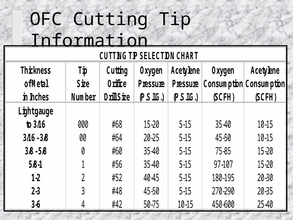
CUTTING TIP SELECTION CHART
Thickness Tip Cutting Oxygen Acetylene Oxygen Acetyleneof Metal Size Orifice Pressure Pressure Consumption Consumption
in Inches Number Drill Size (P.S.I.G.) (P.S.I.G.) (SCFH) (SCFH)Light gauge
to 3/16 000 #68 15-20 5-15 35-40 10-153/16 - 3/8 00 #64 20-25 5-15 45-50 10-153/8 - 5/8 0 #60 35-40 5-15 75-85 15-20
5/8-1 1 #56 35-40 5-15 97-107 15-201-2 2 #52 40-45 5-15 180-195 20-302-3 3 #48 45-50 5-15 270-290 20-353-6 4 #42 50-75 10-15 450-600 25-40
OFC Cutting Tip Information