owon oscilloscope installation and use guide i. pc ... · the above two are both fit for windows...
TRANSCRIPT

OWON Oscilloscope Installation and Use Guide
Welcome to use Oscilloscope analysis software. The kind of communication software is use to acquire, store, analyze and display the data. The instruction book and the following helps are for your reference.
I. PC Software USB Driver Install Guide
USB with better rate and reliability is a kind of data transmission mode to widely use in connecting with PC.(ps: USB interface of Hand Hold type device series is mini USB. Please refer the device instruction)
The serial port is another kind of transmission mode in some outdated PC as a supplementary in failure of USB transmission.
The above two are both fit for Windows NT(2000, XP, Vista),while USB driver in Win 98 only for manual installation.
(1). For Windows XP or Windows 2000 (1-1-1)
Notice: for both x86 and x64. Plug into the running well device to open [Found New Hardware Wizard] dialog.
Or you can right click [My Computer] and select [Manage], in the left area of opened [Computer Management] select [Device Manager] , double click the item [USB Device] with “?” in the middle area to open the Wizard,
In the Wizard, select [No, not this time] ,
Page 1 of 21OWON Oscilloscope Installation and Use Guide
07/18/11file:///C:/Osc_Owon_Guide.htm
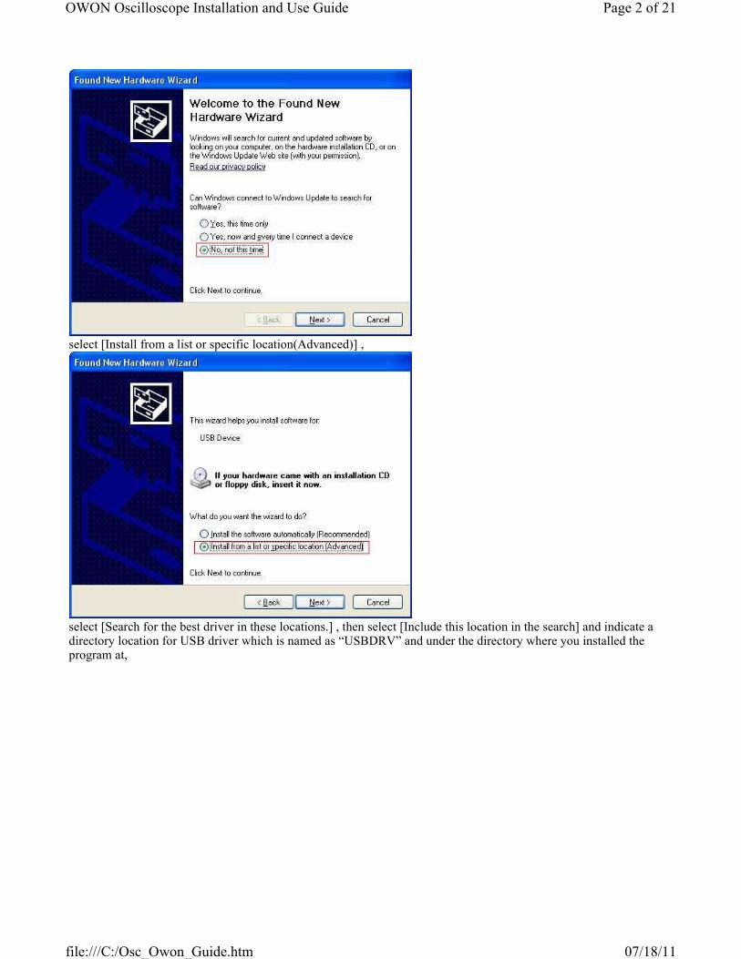
select [Install from a list or specific location(Advanced)] ,
select [Search for the best driver in these locations.] , then select [Include this location in the search] and indicate a directory location for USB driver which is named as “USBDRV” and under the directory where you installed the program at,
Page 2 of 21OWON Oscilloscope Installation and Use Guide
07/18/11file:///C:/Osc_Owon_Guide.htm

Then the installation is running,
And complete,
Page 3 of 21OWON Oscilloscope Installation and Use Guide
07/18/11file:///C:/Osc_Owon_Guide.htm
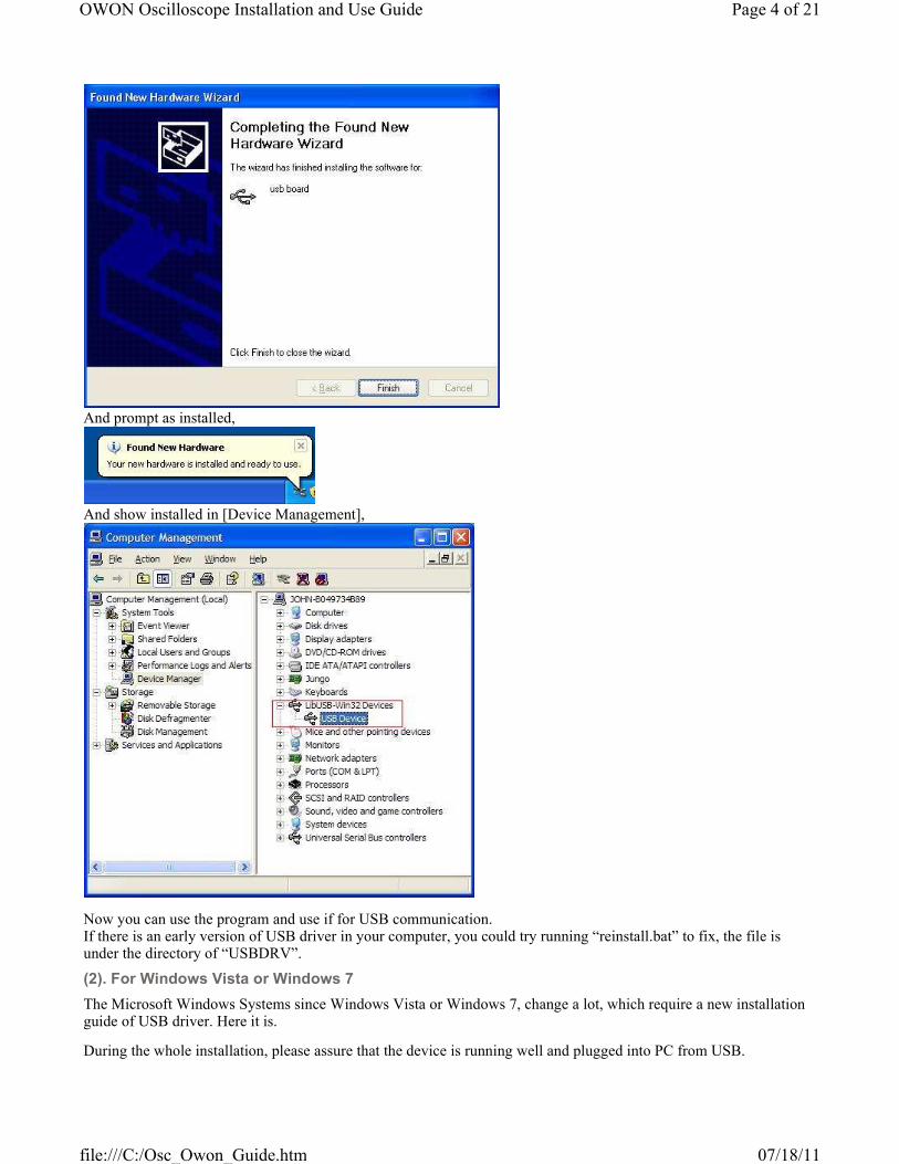
And prompt as installed,
And show installed in [Device Management],
Now you can use the program and use if for USB communication.If there is an early version of USB driver in your computer, you could try running “reinstall.bat” to fix, the file is under the directory of “USBDRV”.
(2). For Windows Vista or Windows 7
The Microsoft Windows Systems since Windows Vista or Windows 7, change a lot, which require a new installation guide of USB driver. Here it is.
During the whole installation, please assure that the device is running well and plugged into PC from USB.
Page 4 of 21OWON Oscilloscope Installation and Use Guide
07/18/11file:///C:/Osc_Owon_Guide.htm
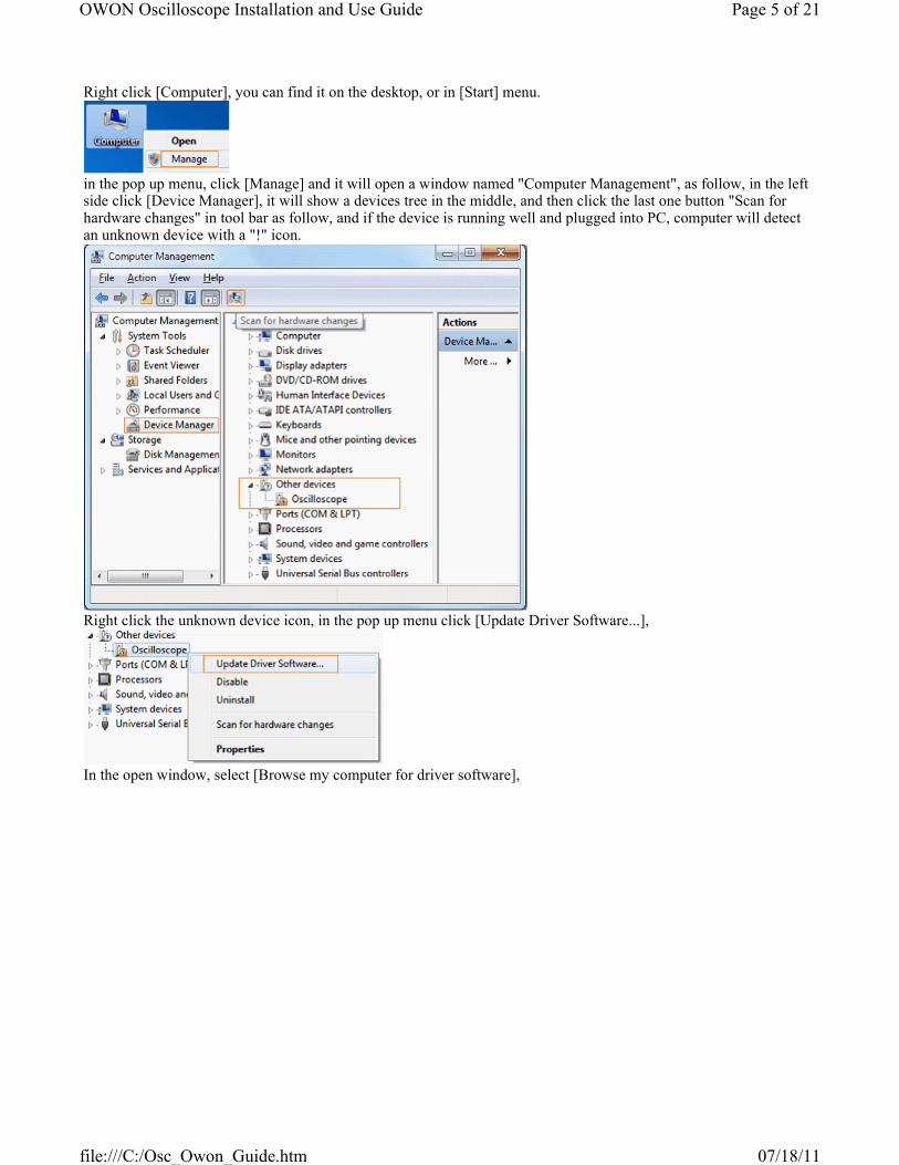
Right click [Computer], you can find it on the desktop, or in [Start] menu.
in the pop up menu, click [Manage] and it will open a window named "Computer Management", as follow, in the left side click [Device Manager], it will show a devices tree in the middle, and then click the last one button "Scan for hardware changes" in tool bar as follow, and if the device is running well and plugged into PC, computer will detect an unknown device with a "!" icon.
Right click the unknown device icon, in the pop up menu click [Update Driver Software...],
In the open window, select [Browse my computer for driver software],
Page 5 of 21OWON Oscilloscope Installation and Use Guide
07/18/11file:///C:/Osc_Owon_Guide.htm
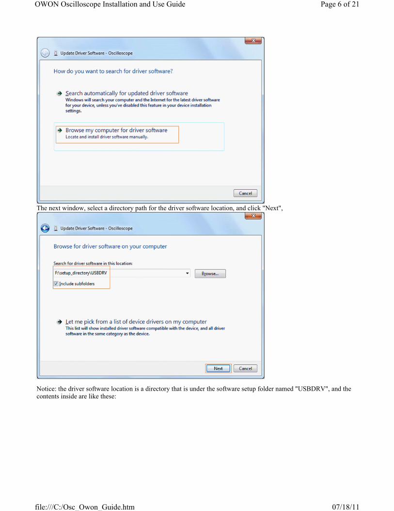
The next window, select a directory path for the driver software location, and click "Next",
Notice: the driver software location is a directory that is under the software setup folder named "USBDRV", and the contents inside are like these:
Page 6 of 21OWON Oscilloscope Installation and Use Guide
07/18/11file:///C:/Osc_Owon_Guide.htm

OK, back to the driver installing, after last "Next" step, the system is installing driver software for you, as follow,
In the course,
It (for Windows XP x86&x64, Windows Vista x86&x64, Windows 7 x86) may open a window named "Windows Security" as below, and just select "Install this driver software anyway" to continue,
Page 7 of 21OWON Oscilloscope Installation and Use Guide
07/18/11file:///C:/Osc_Owon_Guide.htm

Or sometimes it(for Windows 7 x64) may open a window named "Windows Security" as below, and just click "Install" to continue,
And then continue installing,
And finish.Now a successful installation window opens with information "Windows has successfully updated your driver software".
Page 8 of 21OWON Oscilloscope Installation and Use Guide
07/18/11file:///C:/Osc_Owon_Guide.htm

Close the window, have a look at the "Computer Management" window, you will find a device under [LibUSB-Win32 Devices], it should be like this:
Now the USB driver will work.
(3). Serial Port connection
Connect with serial port in PC directly.
II. User Interface
When the software enters into the main interface as Fig 2-2 which has eight parts:
Page 9 of 21OWON Oscilloscope Installation and Use Guide
07/18/11file:///C:/Osc_Owon_Guide.htm
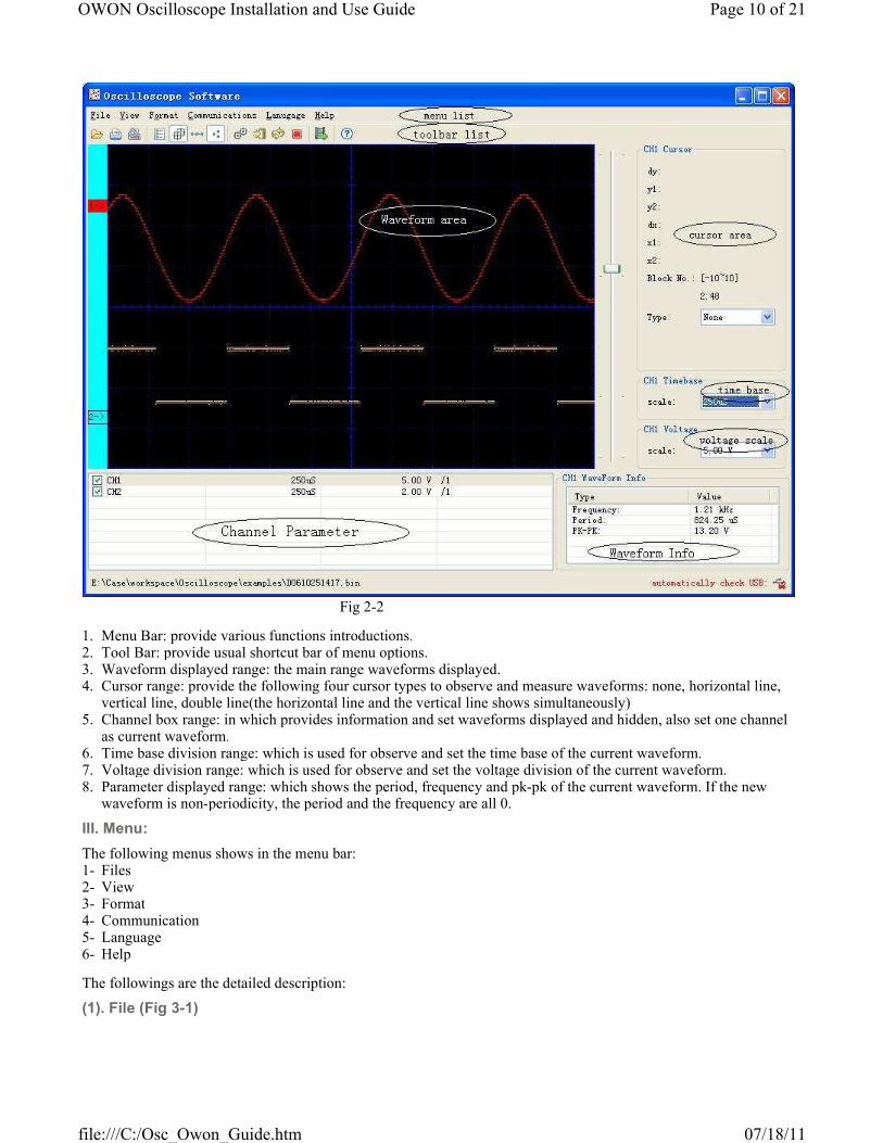
Fig 2-2
1. Menu Bar: provide various functions introductions.2. Tool Bar: provide usual shortcut bar of menu options.3. Waveform displayed range: the main range waveforms displayed.4. Cursor range: provide the following four cursor types to observe and measure waveforms: none, horizontal line,
vertical line, double line(the horizontal line and the vertical line shows simultaneously)5. Channel box range: in which provides information and set waveforms displayed and hidden, also set one channel
as current waveform.6. Time base division range: which is used for observe and set the time base of the current waveform.7. Voltage division range: which is used for observe and set the voltage division of the current waveform.8. Parameter displayed range: which shows the period, frequency and pk-pk of the current waveform. If the new
waveform is non-periodicity, the period and the frequency are all 0.
III. Menu:
The following menus shows in the menu bar:
The followings are the detailed description:
1- Files2- View3- Format4- Communication5- Language6- Help
(1). File (Fig 3-1)
Page 10 of 21OWON Oscilloscope Installation and Use Guide
07/18/11file:///C:/Osc_Owon_Guide.htm

Fig 3-1
1. Open: open the saved files with bin suffix.2. Open recent: save the 10 open recent files3. Save: save the current waveforms as pictures and support bmp, png, gif etc.4. Print preview: preview the print effect5. Print: by printer6. Page setup: set the boundary value for printing7. Exit: exit from the software
(1). View menu(Fig 3-2)
Fig 3-2-1
1. XY waveform: The voltage values of sampling point in CH1, CH2 are shown as X,Y of point coordinates. If only one of the channels, the function is not available.
2. Value list: The sequence of voltage value in sampling point of every channel is shown in the list which could be saved as .txt or .xls (Windows Office Excel) files exported to other documents. The list supply check all or check none, the right part as saved channel and click EXIT to close the list.
Fig 3-2-2: Value list
1. Grids color: Bring out the color dialogue box and change the color.
Page 11 of 21OWON Oscilloscope Installation and Use Guide
07/18/11file:///C:/Osc_Owon_Guide.htm
2. Background color: double click waveform area of display to bring out the color dialogue box and change the background color.3. Grids line: display or hide the grid scale of image background.
(3). Format menu(Fig 3-3)
Fig 3-3-1
1. Data line: draw the sampling point and connect by lines.2. Data point: draw the sampling point discretely3. Waveform inverse: inverse the channel voltage value.
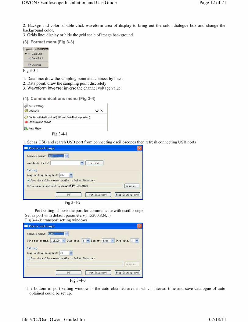
(4). Communications menu (Fig 3-4)
Fig 3-4-1
1. Set as USB and search USB port from connecting oscilloscopes then refresh connecting USB ports
Fig 3-4-2
Port setting: choose the port for communicate with oscilloscope Set as port with default parameters(115200,8,N,1). Fig 3-4-3: transport setting windows
Fig 3-4-3
The bottom of port setting window is the auto obtained area in which interval time and save catalogue of auto obtained could be set up.
Page 12 of 21OWON Oscilloscope Installation and Use Guide
07/18/11file:///C:/Osc_Owon_Guide.htm
2. data acquirement: acquire waveform data from instrument Note: You can get the data from instrument after connecting PC with USB cable and install driver and then choose the
correct interface setting.
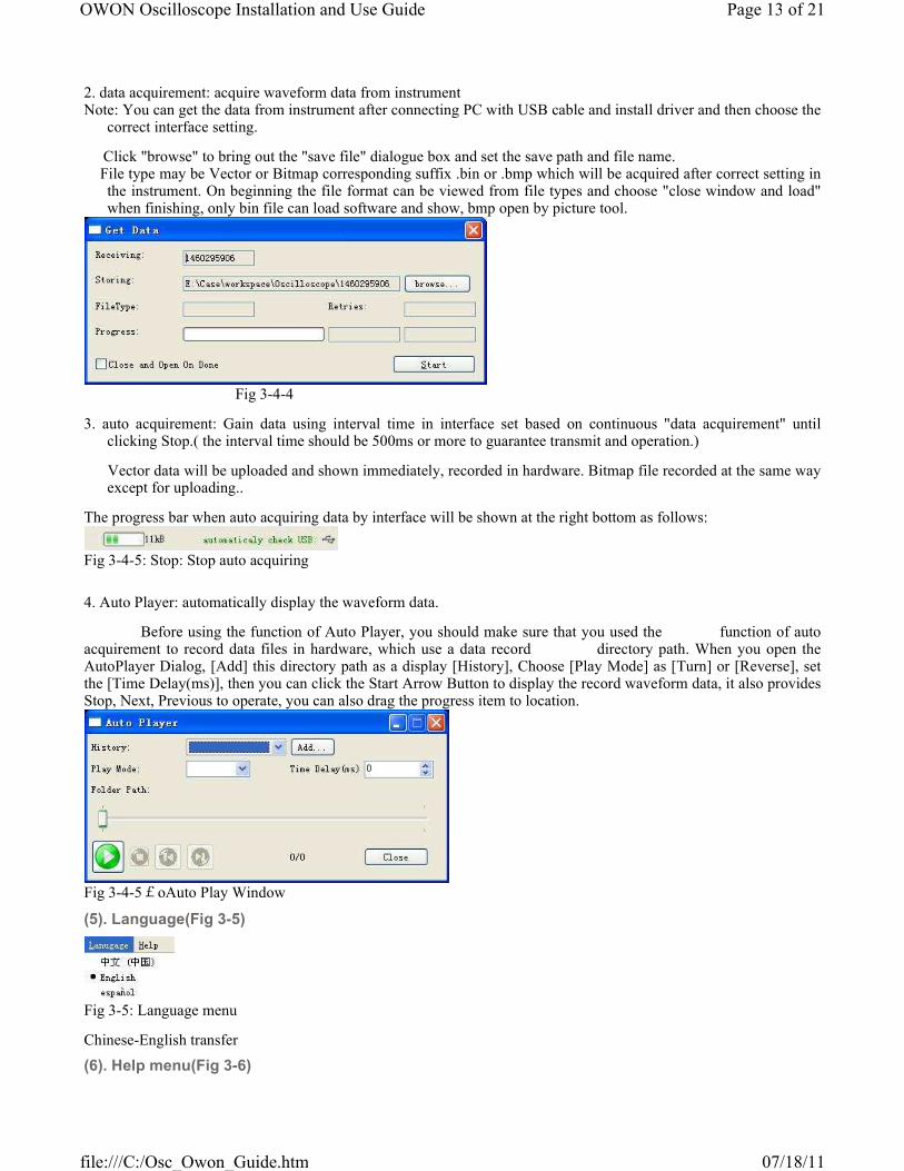
Click "browse" to bring out the "save file" dialogue box and set the save path and file name. File type may be Vector or Bitmap corresponding suffix .bin or .bmp which will be acquired after correct setting in
the instrument. On beginning the file format can be viewed from file types and choose "close window and load" when finishing, only bin file can load software and show, bmp open by picture tool.
Fig 3-4-4
3. auto acquirement: Gain data using interval time in interface set based on continuous "data acquirement" until clicking Stop.( the interval time should be 500ms or more to guarantee transmit and operation.)
Vector data will be uploaded and shown immediately, recorded in hardware. Bitmap file recorded at the same way except for uploading..
The progress bar when auto acquiring data by interface will be shown at the right bottom as follows:
Fig 3-4-5: Stop: Stop auto acquiring
4. Auto Player: automatically display the waveform data.
Before using the function of Auto Player, you should make sure that you used the function of auto acquirement to record data files in hardware, which use a data record directory path. When you open the AutoPlayer Dialog, [Add] this directory path as a display [History], Choose [Play Mode] as [Turn] or [Reverse], set the [Time Delay(ms)], then you can click the Start Arrow Button to display the record waveform data, it also provides Stop, Next, Previous to operate, you can also drag the progress item to location.
Fig 3-4-5£oAuto Play Window
(5). Language(Fig 3-5)
Fig 3-5: Language menu
Chinese-English transfer
(6). Help menu(Fig 3-6)
Page 13 of 21OWON Oscilloscope Installation and Use Guide
07/18/11file:///C:/Osc_Owon_Guide.htm

Fig 3-6-1
1. Help: Open help file
2. Update: Find new version in server and download update as follows:
Fig 3-6-2: About: information
IV. Toolbar:
Toolbar shortcuts common menu items about 12 numbers of knobs as follows:
1 2 3 4 5 6 7 8 9 10 11 12 13 14
icon name function
1 open Open saved files with suffix bin
2 Print preview Preview the print effect
3 print Print by printer
4 Data display Display every voltage sequence of sampling point
5 Display/hide grids Display or hide grids scale of waveform background
6 Display linked waveform
Draw the sampling point and connect in direct line
7 Display data point Draw the sampling point discretely
8 Inverse waveform inverse
9 Communication setting
Set communication parameter
10 Manual acquirement
Open waveform acquirement interface
11 Auto acquirement Auto acquiring files
12 stop Stop auto acquiring
13 AutoPlay Auto play the .bin file
14 help Open help files
IIV. Relevant operations:
Relevant operations
(1).Operation for waveforms display range: (Fig 5-1)
(1). waveform moving up and down1. operation for waveforms display range: (Fig 5-1-1-5)
Page 14 of 21OWON Oscilloscope Installation and Use Guide
07/18/11file:///C:/Osc_Owon_Guide.htm

Firstly, the position as Fig (1->)is the zero voltage position of current waveform.
1) fine adjustment: drag "1->" and make the waveform move up and down on the screen 2) coarse adjustment: drag the ruler slider on the right and make the waveform move up and down, the moving
area is the maximum movable area on time base division ( which could be check the current blocks on the right of cursor area, a block 1/8 of height of the screen.)
(2). waveform move left and right: Move the mouse to the waveform, it becomes icon, then drag the mouse to make the waveform left and right as Fig 5-1-1
Fig 5-1-1
1). Change the color of waveform: double click "1->" to bring out color dialogue box to change the color. 2). The time base division of current waveform can be shown and adjusted in such area (as Fig 5-1-2) which is the
time range about one scale on the vertical line (8 scales in the following), and adjust the scale in the come box, the waveform zoom to the corresponding division with the centre scale mark as centre shaft.(Fig 5-1-3)
Page 15 of 21OWON Oscilloscope Installation and Use Guide
07/18/11file:///C:/Osc_Owon_Guide.htm

Fig 5-1-2
Page 16 of 21OWON Oscilloscope Installation and Use Guide
07/18/11file:///C:/Osc_Owon_Guide.htm

Fig 5-1-3
2. In this aspect, voltage division can be use to show and adjust the current waveform which is one scale on the horizontal line (12 scales in the following, different series with different format which are only for reference.) and adjust the scale in the come box, the waveform zoom to the corresponding division with the zero voltage position as centre shaft.
Page 17 of 21OWON Oscilloscope Installation and Use Guide
07/18/11file:///C:/Osc_Owon_Guide.htm

Fig 5-1-4
(2). Operation in cursor area(Fig 5-2)
There are four cursor types for selection to measure and locate, such as: none, horizontal line, vertical line, double line (that is horizontal line and vertical line display at the same time) (Fig 5-2-1)
Page 18 of 21OWON Oscilloscope Installation and Use Guide
07/18/11file:///C:/Osc_Owon_Guide.htm
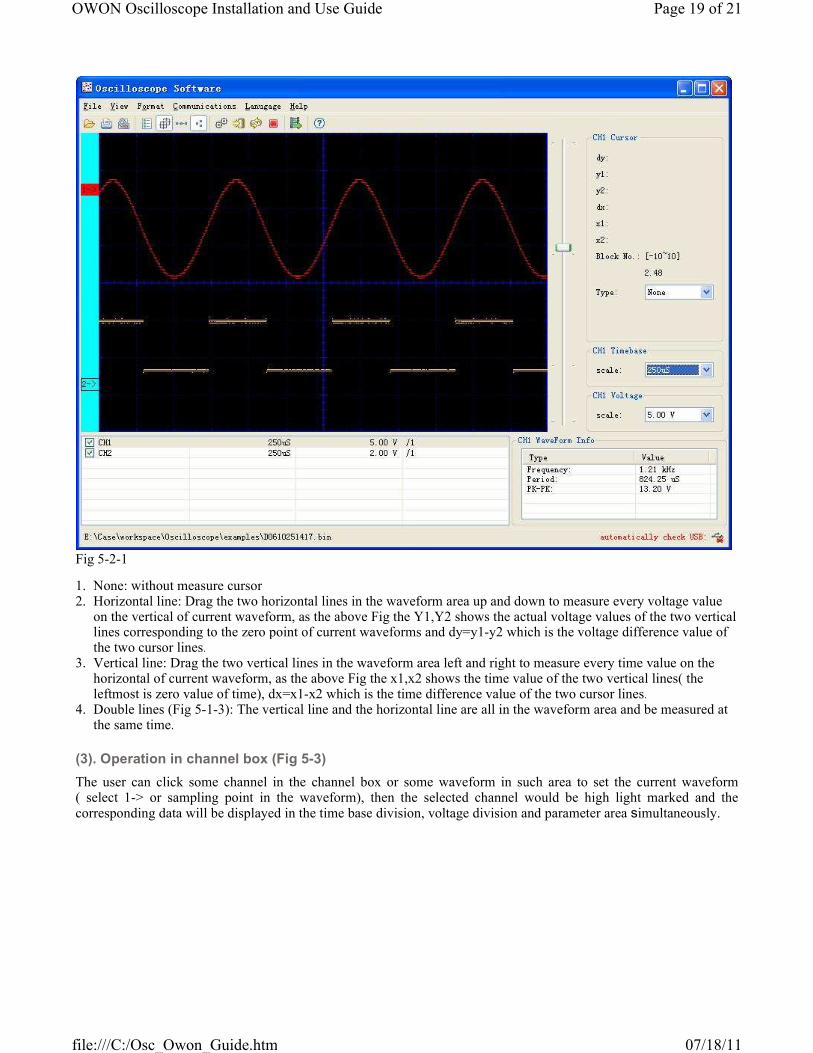
Fig 5-2-1
1. None: without measure cursor2. Horizontal line: Drag the two horizontal lines in the waveform area up and down to measure every voltage value
on the vertical of current waveform, as the above Fig the Y1,Y2 shows the actual voltage values of the two vertical lines corresponding to the zero point of current waveforms and dy=y1-y2 which is the voltage difference value of the two cursor lines.
3. Vertical line: Drag the two vertical lines in the waveform area left and right to measure every time value on the horizontal of current waveform, as the above Fig the x1,x2 shows the time value of the two vertical lines( the leftmost is zero value of time), dx=x1-x2 which is the time difference value of the two cursor lines.
4. Double lines (Fig 5-1-3): The vertical line and the horizontal line are all in the waveform area and be measured at the same time.
(3). Operation in channel box (Fig 5-3)
The user can click some channel in the channel box or some waveform in such area to set the current waveform ( select 1-> or sampling point in the waveform), then the selected channel would be high light marked and the corresponding data will be displayed in the time base division, voltage division and parameter area simultaneously.
Page 19 of 21OWON Oscilloscope Installation and Use Guide
07/18/11file:///C:/Osc_Owon_Guide.htm

Fig 5-3-1
It is index page......Select INDEX and CONTENTS of INSERT menu in the MS-Word, then select INDEX and click OK.
(4). Operation for channel inverse
Operation for inverse: inverse the channel voltage value.
Before channel inversed:
Page 20 of 21OWON Oscilloscope Installation and Use Guide
07/18/11file:///C:/Osc_Owon_Guide.htm

After channel inversed:
Notice: the channel inversed status will keep on and apply for next waveform file's same channel as long as the software is not closed.
Page 21 of 21OWON Oscilloscope Installation and Use Guide
07/18/11file:///C:/Osc_Owon_Guide.htm