owners manualaz685612.vo.msecnd.net/.../xc90_ownersmanual_en.pdf · · 2014-11-19owners manual...
TRANSCRIPT
VOLVO XC90
Owners Manual
WEB EDITION
DEAR VOLVO OWNERTHANK YOU FOR CHOOSING VOLVO
We hope you will enjoy many years of driving pleasure in your
Volvo. The car has been designed for the safety and comfort of
you and your passengers. Volvo is one of the safest cars in the
world. Your Volvo has also been designed to satisfy all current
safety and environmental requirements.
In order to increase your enjoyment of the car, we recommend
that you familiarise yourself with the equipment, instructions
and maintenance information contained in this owner's manual.
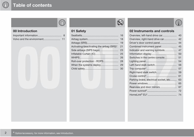
Table of contents
2 * Option/accessory, for more information, see Introduction.
0000 Introduction
Important information................................. 8
Volvo and the environment....................... 11
0101 Safety
Seatbelts................................................... 16
Airbag system........................................... 18
Airbags (SRS)............................................ 19
Activating/deactivating the airbag (SRS)*. 21
Side airbags (SIPS bags).......................... 23
Inflatable Curtain (IC)................................ 25
WHIPS....................................................... 26
Roll-over protection - ROPS..................... 28
When the systems deploy......................... 29
Child safety............................................... 30 0202 Instruments and controls
Overview, left-hand drive car.................... 40
Overview, right-hand drive car.................. 42
Driver's door control panel....................... 44
Combined instrument panel...................... 45
Indicator and warning symbols................. 47
Information display................................... 50
Switches in the centre console................. 51
Lighting panel........................................... 54
Left-hand stalk switch............................... 56
Trip computer*.......................................... 57
Right-hand stalk switch............................ 59
Cruise control*.......................................... 61
Parking brake, electrical socket, etc......... 63
Power windows......................................... 65
Rearview and door mirrors....................... 67
Power sunroof*......................................... 72
HomeLink EU*......................................... 74

Table of contents
* Option/accessory, for more information, see Introduction. 3
0303 Climate control
General information on climate control..... 80
Electronic Climate Control, ECC............... 84
Fuel-driven parking heater*....................... 87
0404 Interior
Front seats................................................ 92
Front seats - Executive ............................ 94
Interior lighting.......................................... 95
Storage spaces in the passenger com-partment.................................................... 97
Storage spaces in the passenger com-partment - Executive .............................. 102
Rear seat................................................. 103
Cargo area.............................................. 105 0505 Locks and alarm
Keys and remote controls....................... 114
Locking and unlocking............................ 116
Child safety locks.................................... 119
Alarm*...................................................... 121

Table of contents
4 * Option/accessory, for more information, see Introduction.
0606 Starting and driving
General.................................................... 126
Refuelling................................................ 128
Starting the engine.................................. 132
Manual gearbox...................................... 134
Automatic gearbox.................................. 135
All-wheel drive*....................................... 138
Brake system.......................................... 139
Stability and traction control system*..... 141
Parking assistance*................................. 143
Blind Spot Information System - BLIS*... 145
Towing and recovery.............................. 149
Start assistance...................................... 151
Driving with a trailer................................ 152
Towing equipment*................................. 154
Detachable towbar*................................ 156
Loading................................................... 160
Adjusting headlamp pattern.................... 161
0707 Wheels and tyres
General.................................................... 168
Tyre pressure.......................................... 171
Warning triangle* and spare wheel*........ 173
Changing wheels.................................... 176
tyre pressure monitoring......................... 178
Emergency puncture repair*................... 180
0808 Car care
Cleaning.................................................. 186
Touching up paintwork........................... 189
Rustproofing........................................... 190
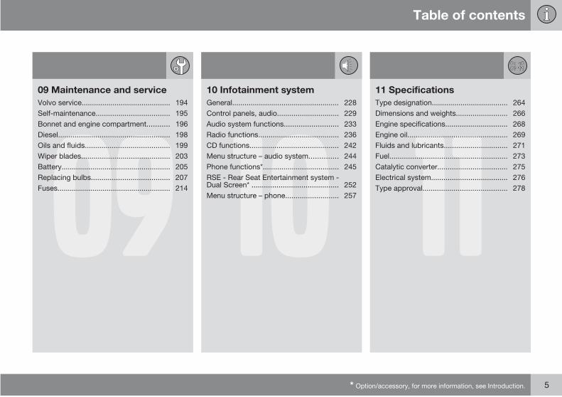
Table of contents
* Option/accessory, for more information, see Introduction. 5
0909 Maintenance and service
Volvo service........................................... 194
Self-maintenance.................................... 195
Bonnet and engine compartment........... 196
Diesel...................................................... 198
Oils and fluids......................................... 199
Wiper blades........................................... 203
Battery..................................................... 205
Replacing bulbs...................................... 207
Fuses....................................................... 214 1010 Infotainment system
General.................................................... 228
Control panels, audio.............................. 229
Audio system functions.......................... 233
Radio functions....................................... 236
CD functions........................................... 242
Menu structure – audio system.............. 244
Phone functions*..................................... 245
RSE - Rear Seat Entertainment system -Dual Screen* .......................................... 252
Menu structure – phone.......................... 257 1111 Specifications
Type designation..................................... 264
Dimensions and weights......................... 266
Engine specifications.............................. 268
Engine oil................................................ 269
Fluids and lubricants............................... 271
Fuel......................................................... 273
Catalytic converter.................................. 275
Electrical system..................................... 276
Type approval......................................... 278
Table of contents
6
1212 Alphabetical Index
Alphabetical Index.................................. 279

Table of contents
7

Introduction
Important information
8
Reading the Owner's Manual
IntroductionA good way of getting to know your new car is
to read the owner's manual, ideally before your
first journey. This will give you the opportunity
to familiarise yourself with new functions, to
see how best to handle the car in different sit-
uations, and to make the best use of all the
car's features. Please pay attention to the
safety instructions contained in the manual.
The equipment described in the owner's man-
ual is not present in all cars . In addition to
standard equipment, this manual also
describes options (factory fitted equipment)
and certain accessories (retrofitted extra
equipment). If you are uncertain over what is
standard or option/accessory then contact
your Volvo dealer.
Volvo cars are adapted for the varying require-
ments of different markets, as well as for
national or local legal requirements and regu-
lations.
The specifications, design features and illus-
trations in this owner's manual are not binding.
We reserve the right to make modifications
without prior notice.
© Volvo Car Corporation
OptionAll types of option/accessory are marked with
an asterisk .
The range of options/accessories for the dif-
ferent car models varies depending on the mar-
ket. The majority of options are factory fitted
and cannot be retrofitted, accessories are ret-
rofitted.
Contact your authorised Volvo dealer for more
information.
Special texts
WARNING
Warning texts advise of a risk of personalinjury.
IMPORTANT
Important texts advise of a risk of materialdamage.
NOTE
NOTE texts give advice or tips that facilitatethe use of features and functions for exam-ple.
FootnoteThere is footnote information in the owner's
manual that is located at the bottom of the
page. This information is an addition to the text
that it refers to via a number. If the footnote
refers to text in a table then letters are used
instead of numbers for referral.
Message textsThere are displays in the car that show text
messages. These text messages are high-
lighted in the owner's manual by means of the
text being slightly larger and printed in grey.
Examples of this are in menu texts and mes-
sage texts on the information display (e.g.
Audio settings).
DecalsThe car contains different types of decal which
are designed to convey important information
in a simple and clear manner. The decals in the
car have the following descending degree of
importance for the warning/information.

Introduction
Important information
9
Warning for personal injury
G031590
Black ISO symbols on yellow warning field,
white text/image on black message field. Dan-
gerous situation which, if not avoided, may
result in serious personal injury or fatality.
Risk of property damage
G03
1592
White ISO symbols on black symbol field, white
text/image on black message field. If a colour
is required then the decal shall be blue. Dan-
gerous situation which, if not avoided, may
result in minor or moderate damage to prop-
erty.
Information
G03
1593
White ISO symbols and white text/image on
black message field.
Procedure listsProcedures where action must be taken in a
certain sequence are numbered in the owner's
manual.
Introduction
Important information
10
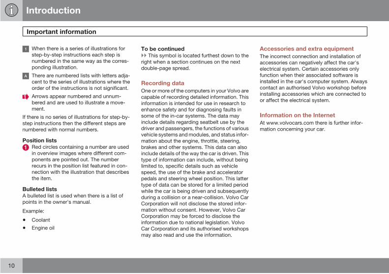
When there is a series of illustrations for
step-by-step instructions each step is
numbered in the same way as the corres-
ponding illustration.
There are numbered lists with letters adja-
cent to the series of illustrations where the
order of the instructions is not significant.
Arrows appear numbered and unnum-
bered and are used to illustrate a move-
ment.
If there is no series of illustrations for step-by-
step instructions then the different steps are
numbered with normal numbers.
Position listsRed circles containing a number are used
in overview images where different com-
ponents are pointed out. The number
recurs in the position list featured in con-
nection with the illustration that describes
the item.
Bulleted listsA bulleted list is used when there is a list of
points in the owner's manual.
Example:
• Coolant
• Engine oil
To be continuedThis symbol is located furthest down to the
right when a section continues on the next
double-page spread.
Recording data
One or more of the computers in your Volvo are
capable of recording detailed information. This
information is intended for use in research to
enhance safety and for diagnosing faults in
some of the in-car systems. The data may
include details regarding seatbelt use by the
driver and passengers, the functions of various
vehicle systems and modules, and status infor-
mation about the engine, throttle, steering,
brakes and other systems. This data can also
include details of the way the car is driven. This
type of information can include, without being
limited to, specific details such as vehicle
speed, the use of the brake and accelerator
pedals and steering wheel position. This latter
type of data can be stored for a limited period
while the car is being driven and subsequently
during a collision or a near-collision. Volvo Car
Corporation will not disclose the stored infor-
mation without consent. However, Volvo Car
Corporation may be forced to disclose the
information due to national legislation. Volvo
Car Corporation and its authorised workshops
may also read and use the information.
Accessories and extra equipment
The incorrect connection and installation of
accessories can negatively affect the car's
electrical system. Certain accessories only
function when their associated software is
installed in the car's computer system. Always
contact an authorised Volvo workshop before
installing accessories which are connected to
or affect the electrical system.
Information on the Internet
At www.volvocars.com there is further infor-
mation concerning your car.
Introduction
Volvo and the environment
* Option/accessory, for more information, see Introduction. 11
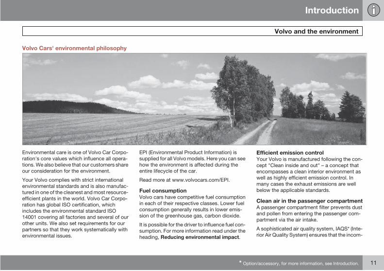
Volvo Cars' environmental philosophy
G00
0000
Environmental care is one of Volvo Car Corpo-
ration's core values which influence all opera-
tions. We also believe that our customers share
our consideration for the environment.
Your Volvo complies with strict international
environmental standards and is also manufac-
tured in one of the cleanest and most resource-
efficient plants in the world. Volvo Car Corpo-
ration has global ISO certification, which
includes the environmental standard ISO
14001 covering all factories and several of our
other units. We also set requirements for our
partners so that they work systematically with
environmental issues.
EPI (Environmental Product Information) is
supplied for all Volvo models. Here you can see
how the environment is affected during the
entire lifecycle of the car.
Read more at www.volvocars.com/EPI.
Fuel consumptionVolvo cars have competitive fuel consumption
in each of their respective classes. Lower fuel
consumption generally results in lower emis-
sion of the greenhouse gas, carbon dioxide.
It is possible for the driver to influence fuel con-
sumption. For more information read under the
heading, Reducing environmental impact.
Efficient emission controlYour Volvo is manufactured following the con-
cept "Clean inside and out" – a concept that
encompasses a clean interior environment as
well as highly efficient emission control. In
many cases the exhaust emissions are well
below the applicable standards.
Clean air in the passenger compartmentA passenger compartment filter prevents dust
and pollen from entering the passenger com-
partment via the air intake.
A sophisticated air quality system, IAQS* (Inte-
rior Air Quality System) ensures that the incom-
Introduction
Volvo and the environment
12
ing air is cleaner than the air in the traffic
outside.
The system consists of an electronic sensor
and a carbon filter. The incoming air is moni-
tored continuously and if there is an increase
in the level of certain unhealthy gases such as
carbon monoxide then the air intake is closed.
Such a situation may arise in heavy traffic,
queues and tunnels for example.
The entry of nitrous oxides, ground-level ozone
and hydrocarbons is prevented by the carbon
filter.
Textile standardThe interior of a Volvo is designed to be plea-
sant and comfortable, even for people with
contact allergies and for asthma sufferers.
Extreme attention has been given to choosing
environmentally-compatible materials. This
means that they also fulfil the requirements in
the Oeko-Tex 100 standard 1, a major advance
towards a healthier passenger compartment
environment.
Oeko-Tex certification covers seatbelts, car-
pets and fabrics for example. The leather in the
upholstery undergoes chromium-free tanning
with plant substances and fulfils the certifica-
tion requirements.
Volvo workshops and the environmentRegular maintenance creates the conditions
for a long service life and low fuel consumption
for your car. In this way you contribute to a
cleaner environment. When Volvo's workshops
are entrusted with the service and mainte-
nance of your car it becomes part of our sys-
tem. We make clear demands regarding the
way in which our workshops are designed in
order to prevent spills and discharges into the
environment. Our workshop staff have the
knowledge and the tools required to guarantee
good environmental care.
Reducing environmental impactYou can easily help reduce environmental
impact, for example, by driving economically
and by servicing and maintaining the car
according to the instructions in the owner's
manual.
The following additional advice will help you to
do your bit for the environment:
• Decrease fuel consumption by choosingECO tyre pressure, see page 171.
• A roof load and ski box increase air resis-tance, leading to higher fuel consumption.Remove them directly after use.
• Remove unnecessary items from the car.The greater the load the higher the fuelconsumption.
• If the car is equipped with an engine blockheater, always use it before starting fromcold. This reduces fuel consumption andexhaust emissions.
• Drive gently and avoid braking too hard.
• Drive in the highest gear possible. Lowengine speeds result in lower fuel con-sumption.
• Use engine braking to slow down.
• Avoid letting the engine idle. Pay attentionto local regulations. Switch off the enginewhen stationary for longer periods.
• Always dispose of environmentally hazar-dous waste, such as batteries and oils, inan environmentally safe manner. If uncer-tain about disposal, consult an authorisedVolvo workshop for advice.
• Service your car regularly.
• High speed increases consumption con-siderably due to increased wind resis-tance. A doubling of speed increases windresistance 4 times.
These hints will help reduce fuel consumption
without increasing travel time or lessening the
enjoyment of driving. Apart from being kind to
1 More information on www.oekotex.com
Introduction
Volvo and the environment
13
your car, you'll be saving money - and the
Earth's resources.

G02
0871
14 * Option/accessory, for more information, see Introduction.
Seatbelts................................................................................................. 16
Airbag system......................................................................................... 18
Airbags (SRS).......................................................................................... 19
Activating/deactivating the airbag (SRS)*............................................... 21
Side airbags (SIPS bags)........................................................................ 23
Inflatable Curtain (IC)............................................................................... 25
WHIPS..................................................................................................... 26
Roll-over protection - ROPS................................................................... 28
When the systems deploy....................................................................... 29
Child safety............................................................................................. 30
01SAFETY
01 Safety
Seatbelts01
16
Always use a seatbelt
G02
0104
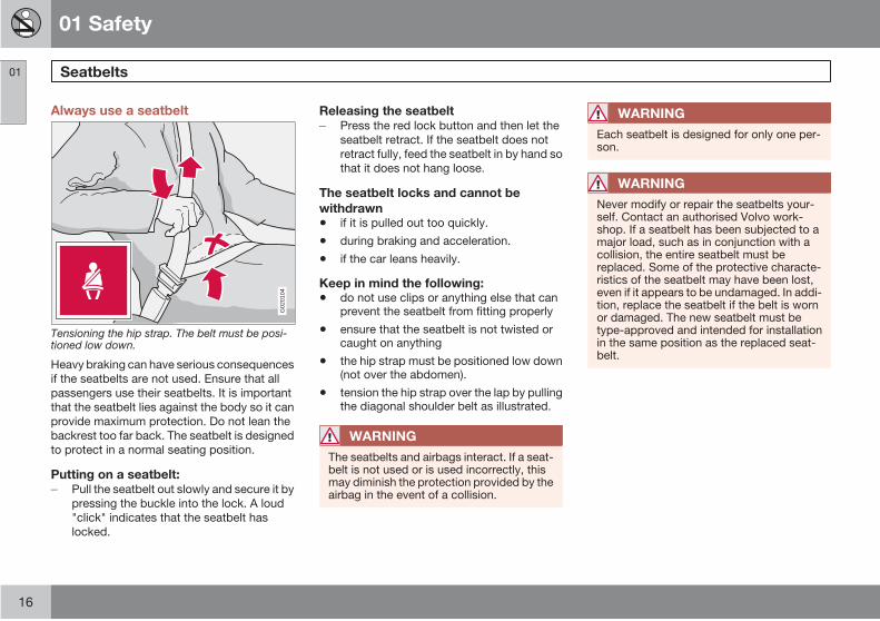
Tensioning the hip strap. The belt must be posi-tioned low down.
Heavy braking can have serious consequences
if the seatbelts are not used. Ensure that all
passengers use their seatbelts. It is important
that the seatbelt lies against the body so it can
provide maximum protection. Do not lean the
backrest too far back. The seatbelt is designed
to protect in a normal seating position.
Putting on a seatbelt:Pull the seatbelt out slowly and secure it by
pressing the buckle into the lock. A loud
"click" indicates that the seatbelt has
locked.
Releasing the seatbeltPress the red lock button and then let the
seatbelt retract. If the seatbelt does not
retract fully, feed the seatbelt in by hand so
that it does not hang loose.
The seatbelt locks and cannot be
withdrawn
• if it is pulled out too quickly.
• during braking and acceleration.
• if the car leans heavily.
Keep in mind the following:
• do not use clips or anything else that canprevent the seatbelt from fitting properly
• ensure that the seatbelt is not twisted orcaught on anything
• the hip strap must be positioned low down(not over the abdomen).
• tension the hip strap over the lap by pullingthe diagonal shoulder belt as illustrated.
WARNING
The seatbelts and airbags interact. If a seat-belt is not used or is used incorrectly, thismay diminish the protection provided by theairbag in the event of a collision.
WARNING
Each seatbelt is designed for only one per-son.
WARNING
Never modify or repair the seatbelts your-self. Contact an authorised Volvo work-shop. If a seatbelt has been subjected to amajor load, such as in conjunction with acollision, the entire seatbelt must bereplaced. Some of the protective characte-ristics of the seatbelt may have been lost,even if it appears to be undamaged. In addi-tion, replace the seatbelt if the belt is wornor damaged. The new seatbelt must betype-approved and intended for installationin the same position as the replaced seat-belt.
01 Safety
Seatbelts 01
17
Seatbelts and pregnancy
G02
0105
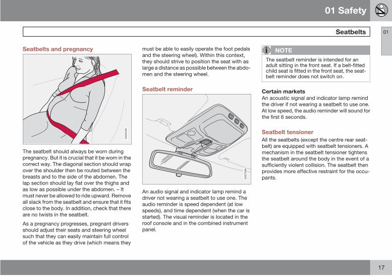
The seatbelt should always be worn during
pregnancy. But it is crucial that it be worn in the
correct way. The diagonal section should wrap
over the shoulder then be routed between the
breasts and to the side of the abdomen. The
lap section should lay flat over the thighs and
as low as possible under the abdomen. – It
must never be allowed to ride upward. Remove
all slack from the seatbelt and ensure that it fits
close to the body. In addition, check that there
are no twists in the seatbelt.
As a pregnancy progresses, pregnant drivers
should adjust their seats and steering wheel
such that they can easily maintain full control
of the vehicle as they drive (which means they
must be able to easily operate the foot pedals
and the steering wheel). Within this context,
they should strive to position the seat with as
large a distance as possible between the abdo-
men and the steering wheel.
Seatbelt reminder
G02
7049
An audio signal and indicator lamp remind a
driver not wearing a seatbelt to use one. The
audio reminder is speed dependent (at low
speeds), and time dependent (when the car is
started). The visual reminder is located in the
roof console and in the combined instrument
panel.
NOTE
The seatbelt reminder is intended for anadult sitting in the front seat. If a belt-fittedchild seat is fitted in the front seat, the seat-belt reminder does not switch on.
Certain marketsAn acoustic signal and indicator lamp remind
the driver if not wearing a seatbelt to use one.
At low speed, the audio reminder will sound for
the first 6 seconds.
Seatbelt tensioner
All the seatbelts (except the centre rear seat-
belt) are equipped with seatbelt tensioners. A
mechanism in the seatbelt tensioner tightens
the seatbelt around the body in the event of a
sufficiently violent collision. The seatbelt then
provides more effective restraint for the occu-
pants.
01 Safety
Airbag system01
18
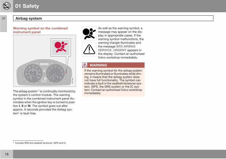
Warning symbol on the combinedinstrument panel
G02
7953
The airbag system 1 is continually monitored by
the system's control module. The warning
symbol in the combined instrument panel illu-
minates when the ignition key is turned to posi-
tion I, II or III. The symbol goes out after
approx. 6 seconds provided the Airbag sys-
tem1 is fault-free.
As well as the warning symbol, a
message may appear on the dis-
play in appropriate cases. If the
warning symbol malfunctions, the
warning triangle illuminates and
the message SRS AIRBAG
SERVICE. URGENT appears in
the display. Contact an authorised
Volvo workshop immediately.
WARNING
If the warning symbol for the airbag systemremains illuminated or illuminates while driv-ing, it means that the airbag system doesnot have full functionality. The symbol canindicate a fault in the seatbelt tensioner sys-tem, SIPS, the SRS system or the IC sys-tem. Contact an authorised Volvo workshopimmediately.
1 Includes SRS and seatbelt tensioner, SIPS and IC.
01 Safety
Airbags (SRS) 01
19
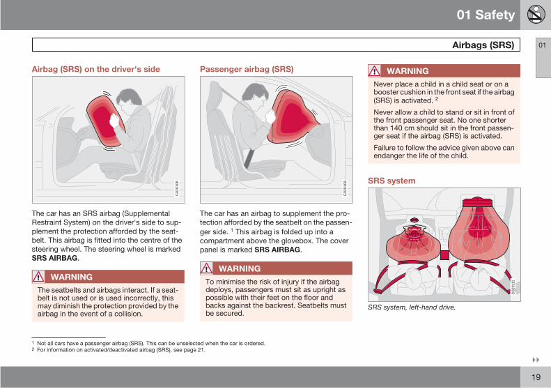
Airbag (SRS) on the driver's side
G02
0108
The car has an SRS airbag (Supplemental
Restraint System) on the driver's side to sup-
plement the protection afforded by the seat-
belt. This airbag is fitted into the centre of the
steering wheel. The steering wheel is marked
SRS AIRBAG.
WARNING
The seatbelts and airbags interact. If a seat-belt is not used or is used incorrectly, thismay diminish the protection provided by theairbag in the event of a collision.
Passenger airbag (SRS)
G02
0109
The car has an airbag to supplement the pro-
tection afforded by the seatbelt on the passen-
ger side. 1 This airbag is folded up into a
compartment above the glovebox. The cover
panel is marked SRS AIRBAG.
WARNING
To minimise the risk of injury if the airbagdeploys, passengers must sit as upright aspossible with their feet on the floor andbacks against the backrest. Seatbelts mustbe secured.
WARNING
Never place a child in a child seat or on abooster cushion in the front seat if the airbag(SRS) is activated. 2
Never allow a child to stand or sit in front ofthe front passenger seat. No one shorterthan 140 cm should sit in the front passen-ger seat if the airbag (SRS) is activated.
Failure to follow the advice given above canendanger the life of the child.
SRS system
G02
0111
SRS system, left-hand drive.
1 Not all cars have a passenger airbag (SRS). This can be unselected when the car is ordered.2 For information on activated/deactivated airbag (SRS), see page 21.
01 Safety
Airbags (SRS)01
20
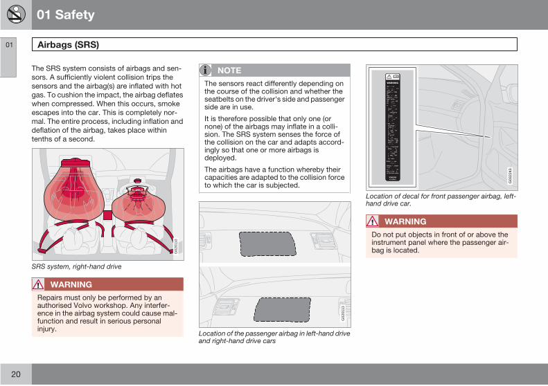
The SRS system consists of airbags and sen-
sors. A sufficiently violent collision trips the
sensors and the airbag(s) are inflated with hot
gas. To cushion the impact, the airbag deflates
when compressed. When this occurs, smoke
escapes into the car. This is completely nor-
mal. The entire process, including inflation and
deflation of the airbag, takes place within
tenths of a second.
G02
0110
SRS system, right-hand drive
WARNING
Repairs must only be performed by anauthorised Volvo workshop. Any interfer-ence in the airbag system could cause mal-function and result in serious personalinjury.
NOTE
The sensors react differently depending onthe course of the collision and whether theseatbelts on the driver's side and passengerside are in use.
It is therefore possible that only one (ornone) of the airbags may inflate in a colli-sion. The SRS system senses the force ofthe collision on the car and adapts accord-ingly so that one or more airbags isdeployed.
The airbags have a function whereby theircapacities are adapted to the collision forceto which the car is subjected.
G02
0113
Location of the passenger airbag in left-hand driveand right-hand drive cars
G03
2243
Location of decal for front passenger airbag, left-hand drive car.
WARNING
Do not put objects in front of or above theinstrument panel where the passenger air-bag is located.
01 Safety
Activating/deactivating the airbag (SRS)* 01
* Option/accessory, for more information, see Introduction. 21
Key switch off - PACOS
General informationThe airbag (SRS) for the front passenger seat
can be deactivated if the car is equipped with
a switch, PACOS (Passenger Airbag Cut Off
Switch). For information on how to activate/
deactivate, see under the heading Activating/
deactivating.
Key switch off/switchThe switch for the passenger airbag, PACOS
(Passenger Airbag Cut Off Switch), is located
on the passenger end of the instrument panel
and is accessible when the passenger door is
open (see under the heading, Activating/deac-
tivating below).
Check that the switch is in the required posi-
tion. Volvo recommends that the key blade is
used to change position.
WARNING
Failure to follow the advice given above canendanger life.
WARNING
Never place a child in a child seat or on abooster cushion in the front seat if the airbagis activated. Failure to follow this advicecould endanger the life of the child.
WARNING
If the car is equipped with a front passengerairbag (SRS), but does not have PACOS, theairbag will always be activated.
WARNING
Do not allow anyone to sit in the front pas-senger seat if the text message in the rear-view mirror indicates that the airbag (SRS)is deactivated and if the warning symbol forthe airbag system is also displayed on thecombined instrument panel. This indicatesthat there has been a severe malfunction.Contact an authorised Volvo workshopimmediately.
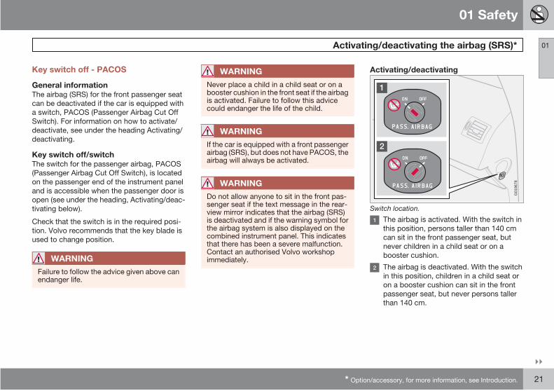
Activating/deactivating
G01
9678
Switch location.
The airbag is activated. With the switch in
this position, persons taller than 140 cm
can sit in the front passenger seat, but
never children in a child seat or on a
booster cushion.
The airbag is deactivated. With the switch
in this position, children in a child seat or
on a booster cushion can sit in the front
passenger seat, but never persons taller
than 140 cm.
01 Safety
Activating/deactivating the airbag (SRS)*01
22 * Option/accessory, for more information, see Introduction.
WARNING
Activated airbag (passenger seat):
Never place a child in a child seat or on abooster cushion on the front passenger seatwhen the airbag is activated. This alsoapplies to anyone shorter than 140 cm
Deactivated airbag (passenger seat):
No one taller than 140 cm should ever sit inthe front passenger seat when the airbag isdeactivated.
Failure to follow the advice given above canendanger life.
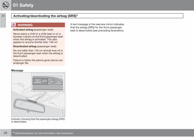
Message
G02
7050
Indicator showing that the passenger airbag (SRS)is deactivated.
A text message in the rearview mirror indicates
that the airbag (SRS) for the front passenger
seat is deactivated (see preceding illustration).
01 Safety
Side airbags (SIPS bags) 01
23
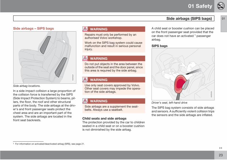
Side airbags – SIPS bags
G02
0118
Side airbag locations.
In a side impact collision a large proportion of
the collision force is transferred by the SIPS
(Side Impact Protection System) to beams, pil-
lars, the floor, the roof and other structural
parts of the body. The side airbags at the driv-
er's and front passenger seats protect the
chest area and are an important part of the
system. The side airbags are located in the
front seat backrests.
WARNING
Repairs must only be performed by anauthorised Volvo workshop.
Work on the SIPS bag system could causemalfunction and result in serious personalinjury.
WARNING
Do not put objects in the area between theoutside of the seat and the door panel, sincethis area is required by the side airbag.
WARNING
Use only seat covers approved by Volvo.Other seat covers may impede the opera-tion of the side airbags.
WARNING
Side airbags are a supplement the seat-belts. Always use a seatbelt.
Child seats and side airbagsThe protection provided by the car to children
seated in a child seat or on a booster cushion
is not diminished by the side airbag.
A child seat or booster cushion can be placed
on the front passenger seat provided that the
car does not have an activated 1 passenger
airbag.
SIPS bags
G02
5315
Driver's seat, left-hand drive
The SIPS bag system consists of side airbags
and sensors. A sufficiently violent collision trips
the sensors and the side airbags are inflated.
1 For information on activated/deactivated airbag (SRS), see page 21.
01 Safety
Side airbags (SIPS bags)01
24
G02
5316
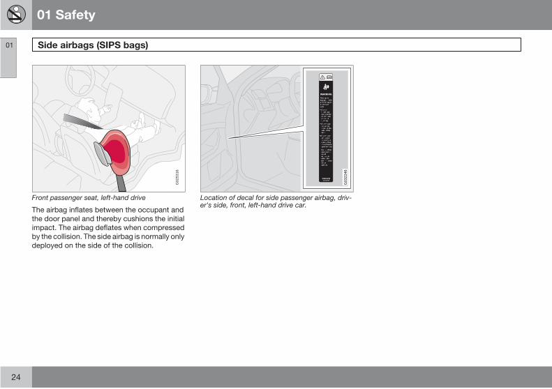
Front passenger seat, left-hand drive
The airbag inflates between the occupant and
the door panel and thereby cushions the initial
impact. The airbag deflates when compressed
by the collision. The side airbag is normally only
deployed on the side of the collision.
G03
2246
Location of decal for side passenger airbag, driv-er's side, front, left-hand drive car.

01 Safety
Inflatable Curtain (IC) 01
25
Properties
G02
7047
The inflatable curtain IC (Inflatable Curtain) is a
supplement to the SIPS and the airbags. It is
fitted in the headlining along both sides of the
roof and protects all of the vehicle's outer
seats. A sufficiently violent collision trips the
sensors and the inflatable curtain is inflated.
The inflatable curtain helps to prevent the
driver and passengers from striking their heads
on the inside of the car during a collision.
WARNING
Never hang or fasten anything on the roofhandles. The hook is only designed for lightclothing (not for solid objects such asumbrellas for example).
Do not screw or install anything onto thecar's headlining, door pillars or side panels.This could compromise the intended pro-tection. Only ever use Volvo genuine partsthat are approved for placement in theseareas.
WARNING
Do not load the car higher than 50 mm underthe top edge of the side windows. Other-wise, the intended protection of the inflat-able curtain, which is concealed in theheadlining, may be compromised.
WARNING
The inflatable curtain is a supplement to theseatbelts.
Always use a seatbelt.
01 Safety
WHIPS01
26
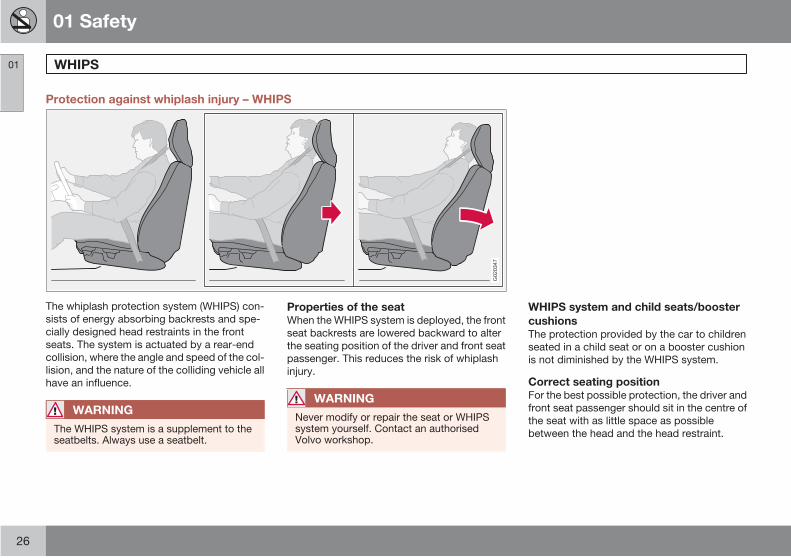
Protection against whiplash injury – WHIPS
G02
0347
The whiplash protection system (WHIPS) con-
sists of energy absorbing backrests and spe-
cially designed head restraints in the front
seats. The system is actuated by a rear-end
collision, where the angle and speed of the col-
lision, and the nature of the colliding vehicle all
have an influence.
WARNING
The WHIPS system is a supplement to theseatbelts. Always use a seatbelt.
Properties of the seatWhen the WHIPS system is deployed, the front
seat backrests are lowered backward to alter
the seating position of the driver and front seat
passenger. This reduces the risk of whiplash
injury.
WARNING
Never modify or repair the seat or WHIPSsystem yourself. Contact an authorisedVolvo workshop.
WHIPS system and child seats/booster
cushionsThe protection provided by the car to children
seated in a child seat or on a booster cushion
is not diminished by the WHIPS system.
Correct seating positionFor the best possible protection, the driver and
front seat passenger should sit in the centre of
the seat with as little space as possible
between the head and the head restraint.
01 Safety
WHIPS 01
27
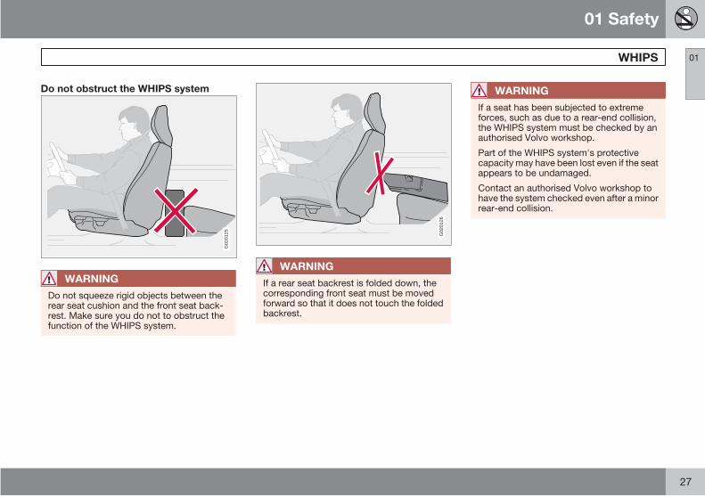
Do not obstruct the WHIPS system
G02
0125
WARNING
Do not squeeze rigid objects between therear seat cushion and the front seat back-rest. Make sure you do not to obstruct thefunction of the WHIPS system.
G02
0126
WARNING
If a rear seat backrest is folded down, thecorresponding front seat must be movedforward so that it does not touch the foldedbackrest.
WARNING
If a seat has been subjected to extremeforces, such as due to a rear-end collision,the WHIPS system must be checked by anauthorised Volvo workshop.
Part of the WHIPS system's protectivecapacity may have been lost even if the seatappears to be undamaged.
Contact an authorised Volvo workshop tohave the system checked even after a minorrear-end collision.

01 Safety
Roll-over protection - ROPS01
28
Function
Volvo's Roll-Over Protection System (ROPS)
has been designed to reduce the risk of the car
overturning and to provide the best possible
protection in the event of such an accident.
The system consists of:
• A stabiliser system, RSC (Roll StabilityControl) that minimises the risk of over-turning during sudden evasive manoeu-vres or the like or if the car skids.
• Increased protection for the driver andpassengers through a reinforced body,inflatable curtains and seatbelt tensionersin all seats. See also pages 17 and 25.
The RSC system uses a gyro sensor which
registers changes in the car's lateral inclination
angle. This information is then used to calcu-
late the risk for overturning. If a risk is detected,
the DSTC system is engaged, engine speed is
reduced and one or more wheels are braked
until the car returns to a stable position.
For more information on the DSTC system, see
page 141.
WARNING
Under normal driving conditions, the RSCsystem improves the car's road safety, butthis must not be taken as a reason toincrease speed. Always follow the usualprecautions for safe driving.
01 Safety
When the systems deploy 01
29
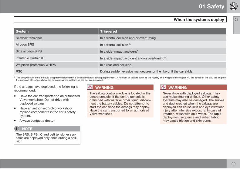
System Triggered
Seatbelt tensioner In a frontal collision and/or overturning.
Airbags SRS In a frontal collision A
Side airbags SIPS In a side-impact accidentA
Inflatable Curtain IC In a side-impact accident and/or overturningA.
Whiplash protection WHIPS In a rear-end collision.
RSC During sudden evasive manoeuvres or the like or if the car skids.
A The bodywork of the car could be greatly deformed in a collision without airbag deployment. A number of factors such as the rigidity and weight of the object hit, the speed of the car, the angle ofthe collision etc. affects how the different safety systems of the car are activated.
If the airbags have deployed, the following is
recommended:
• Have the car transported to an authorisedVolvo workshop. Do not drive withdeployed airbags.
• Have an authorised Volvo workshopreplace components in the car's safetysystem.
• Always contact a doctor.
NOTE
The SRS, SIPS, IC and belt tensioner sys-tems are deployed only once during a colli-sion
WARNING
The airbag control module is located in thecentre console. If the centre console isdrenched with water or other liquid, discon-nect the battery cables. Do not attempt tostart the car since the airbags may deploy.Have the car transported to an authorisedVolvo workshop.
WARNING
Never drive with deployed airbags. Theycan make steering difficult. Other safetysystems may also be damaged. The smokeand dust created when the airbags aredeployed can cause skin and eye irritation/injury after intensive exposure. In case ofirritation, wash with cold water. The rapiddeployment sequence and airbag fabricmay cause friction and skin burns.
01 Safety
Child safety01
30
Children should sit comfortably andsafely
The position of a child in the car and the choice
of equipment are dictated by the child's weight
and size. For more information, see
page 31.
NOTE
Regulations regarding the placement ofchildren in cars vary from country to coun-try. Check what does apply.
Children of all ages and sizes must always sit
correctly secured in the car. Never allow a child
to sit on the knee of a passenger.
Volvo's own child safety equipment is
designed for your car. Use Volvo genuine
equipment to best ensure that the mounting
points and attachments are correctly posi-
tioned and are sufficiently strong.
NOTE
In the event of questions when fitting childsafety products, contact the manufacturerfor clearer instructions.
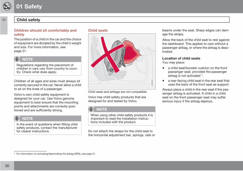
Child seats
G02
0128
Child seats and airbags are not compatible.
Volvo has child safety products that are
designed for and tested by Volvo.
NOTE
When using other child safety products it isimportant to read the installation instruc-tions included with the product.
Do not attach the straps for the child seat to
the horizontal adjustment bar, springs, rails or
beams under the seat. Sharp edges can dam-
age the straps.
Allow the back of the child seat to rest against
the dashboard. This applies to cars without a
passenger airbag, or where the airbag is deac-
tivated.
Location of child seatsYou may place:
• a child seat/booster cushion on the frontpassenger seat, provided the passenger
airbag is not activated 1.
• a rear-facing child seat in the rear seat thatuses the back of the front seat as support.
Always place a child in the rear seat if the pas-
senger airbag is activated. A child in a child
seat on the front passenger seat may suffer
serious injury if the airbag deploys.
1 For information on activating/deactivating the airbag (SRS), see page 21.
01 Safety
Child safety 01
31
WARNING
Never place a child in a child seat or on abooster cushion in the front seat if the airbag(SRS) is activated. 2
No one shorter than 140 cm should sit in thefront passenger seat if the airbag (SRS) isactivated.
Failure to follow the advice given above canendanger the life of the child.
WARNING
Booster cushions/child seats with steelbraces or some other design that could reston the seatbelt buckle's opening buttonmust not be used, as they could cause theseatbelt buckle to open accidentally.
Do not allow the upper section of the childseat to rest against the windscreen.
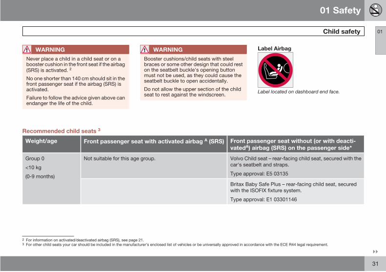
Label Airbag
Label located on dashboard end face.
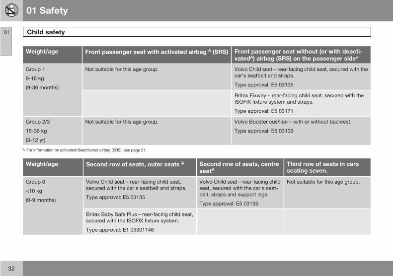
Recommended child seats 3
Weight/age Front passenger seat with activated airbag A (SRS) Front passenger seat without (or with deacti-vatedA) airbag (SRS) on the passenger side*
Group 0
<10 kg
(0-9 months)
Not suitable for this age group. Volvo Child seat – rear-facing child seat, secured with the
car's seatbelt and straps.
Type approval: E5 03135
Britax Baby Safe Plus – rear-facing child seat, secured
with the ISOFIX fixture system.
Type approval: E1 03301146
2
3 For other child seats your car should be included in the manufacturer's enclosed list of vehicles or be universally approved in accordance with the ECE R44 legal requirement.For information on activated/deactivated airbag (SRS), see page 21.
01 Safety
Child safety01
32
Weight/age Front passenger seat with activated airbag A (SRS) Front passenger seat without (or with deacti-vatedA) airbag (SRS) on the passenger side*
Group 1
9-18 kg
(9-36 months)
Not suitable for this age group. Volvo Child seat – rear-facing child seat, secured with the
car's seatbelt and straps.
Type approval: E5 03135
Britax Fixway – rear-facing child seat, secured with the
ISOFIX fixture system and straps.
Type approval: E5 03171
Group 2/3
15-36 kg
(3-12 yr)
Not suitable for this age group. Volvo Booster cushion – with or without backrest.
Type approval: E5 03139
A For information on activated/deactivated airbag (SRS), see page 21.
Weight/age Second row of seats, outer seats A Second row of seats, centreseatA
Third row of seats in carsseating seven.
Group 0
<10 kg
(0-9 months)
Volvo Child seat – rear-facing child seat,
secured with the car's seatbelt and straps.
Type approval: E5 03135
Volvo Child seat – rear-facing child
seat, secured with the car's seat-
belt, straps and support legs.
Type approval: E5 03135
Not suitable for this age group.
Britax Baby Safe Plus – rear-facing child seat,
secured with the ISOFIX fixture system.
Type approval: E1 03301146
01 Safety
Child safety 01
33
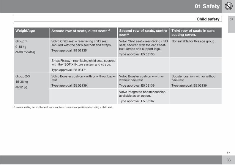
Weight/age Second row of seats, outer seats A Second row of seats, centreseat
Third row of seats in carsseating seven.
Group 1
9-18 kg
(9-36 months)
Volvo Child seat – rear-facing child seat,
secured with the car's seatbelt and straps.
Type approval: E5 03135
Volvo Child seat – rear-facing child
seat, secured with the car's seat-
belt, straps and support legs.
Type approval: E5 03135
Not suitable for this age group.
Britax Fixway – rear-facing child seat, secured
with the ISOFIX fixture system and straps.
Type approval: E5 03171
Group 2/3
15-36 kg
(3-12 yr)
Volvo Booster cushion – with or without back-
rest.
Type approval: E5 03139
Volvo Booster cushion – with or
without backrest.
Type approval: E5 03139
Booster cushion with or without
backrest.
Type approval: E5 03139
Volvo Integrated booster cushion –
available as an option.
Type approval: E5 03167
A In cars seating seven, the seat row must be in its rearmost position when using a child seat.
A
01 Safety
Child safety01
34 * Option/accessory, for more information, see Introduction.
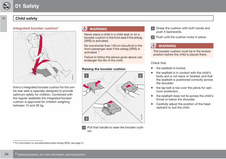
Integrated booster cushion*
G03
1071
Volvo's integrated booster cushion for the cen-
tre rear seat is specially designed to provide
optimum safety for children. Combined with
the regular seatbelts the integrated booster
cushion is approved for children weighing
between 15 and 36 kg.
WARNING
Never place a child in a child seat or on abooster cushion in the front seat if the airbag(SRS) is activated.
No one shorter than 140 cm should sit in thefront passenger seat if the airbag (SRS) isactivated. 4
Failure to follow the advice given above canendanger the life of the child.
Raising the booster cushion
G02
0808
Pull that handle to raise the booster cush-
ion.
Grasp the cushion with both hands and
push it backwards.
Push until the cushion locks in place.
WARNING
The booster cushion must be in the lockedposition before the child is placed there.
Check that:
• the seatbelt is locked.
• the seatbelt is in contact with the child'sbody and is not slack or twisted, and thatthe seatbelt is positioned correctly acrossthe shoulder.
• the lap belt is low over the pelvis for opti-mum protection.
• the seatbelt does not lie across the child'sthroat or below the shoulder.
• Carefully adjust the position of the headrestraint to suit the child.
4 For information on activated/deactivated airbag (SRS), see page 21.
01 Safety
Child safety 01
* Option/accessory, for more information, see Introduction. 35
WARNING
Repair or replacement should only be per-formed by an authorised Volvo workshop.Do not make any modifications or additionsto the booster cushion.
If an integrated booster cushion has beensubjected to a major load, such as in con-junction with a collision, the entire boostercushion must be replaced. Even if thebooster cushion appears to be undamaged,it may not afford the same level of protec-tion. The booster cushion must also bereplaced if it is heavily worn.
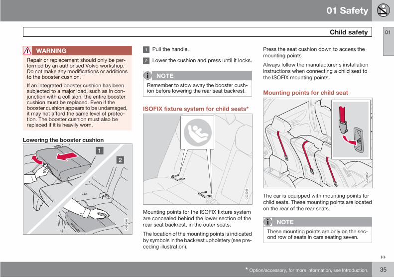
Lowering the booster cushion
G01
4507
Pull the handle.
Lower the cushion and press until it locks.
NOTE
Remember to stow away the booster cush-ion before lowering the rear seat backrest.
ISOFIX fixture system for child seats*
G01
5268
Mounting points for the ISOFIX fixture system
are concealed behind the lower section of the
rear seat backrest, in the outer seats.
The location of the mounting points is indicated
by symbols in the backrest upholstery (see pre-
ceding illustration).
Press the seat cushion down to access the
mounting points.
Always follow the manufacturer's installation
instructions when connecting a child seat to
the ISOFIX mounting points.
Mounting points for child seat
G02
7032
The car is equipped with mounting points for
child seats. These mounting points are located
on the rear of the rear seats.
NOTE
These mounting points are only on the sec-ond row of seats in cars seating seven.
01 Safety
Child safety01
36
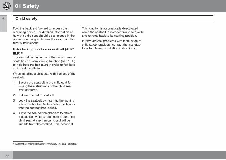
Fold the backrest forward to access the
mounting points. For detailed information on
how the child seat should be tensioned in the
upper mounting points, see the seat manufac-
turer's instructions.
Extra locking function in seatbelt (ALR/
ELR) 5
The seatbelt in the centre of the second row of
seats has an extra locking function (ALR/ELR)
to help hold the belt taunt in order to facilitate
child seat installation.
When installing a child seat with the help of the
seatbelt:
1. Secure the seatbelt in the child seat fol-
lowing the instructions of the child seat
manufacturer.
2. Pull out the entire seatbelt.
3. Lock the seatbelt by inserting the locking
tab in the buckle. A clear "click" indicates
that the seatbelt has locked.
4. Allow the seatbelt mechanism to retract
the seatbelt while stretching it around the
child seat. A mechanical sound will be
audible from the seatbelt. This is normal.
This function is automatically deactivated
when the seatbelt is released from the buckle
and retracts back to its starting position.
If there are any problems with installation of
child safety products, contact the manufac-
turer for clearer installation instructions.
5 Automatic Locking Retractor/Emergency Locking Retractor.
01 Safety
01
37
G02
0901
38 * Option/accessory, for more information, see Introduction.
Overview, left-hand drive car.................................................................. 40
Overview, right-hand drive car................................................................ 42
Driver's door control panel...................................................................... 44
Combined instrument panel.................................................................... 45
Indicator and warning symbols............................................................... 47
Information display.................................................................................. 50
Switches in the centre console............................................................... 51
Lighting panel.......................................................................................... 54
Left-hand stalk switch............................................................................. 56
Trip computer*........................................................................................ 57
Right-hand stalk switch.......................................................................... 59
Cruise control*........................................................................................ 61
Parking brake, electrical socket, etc....................................................... 63
Power windows....................................................................................... 65
Rearview and door mirrors...................................................................... 67
Power sunroof*........................................................................................ 72
HomeLink EU*....................................................................................... 74
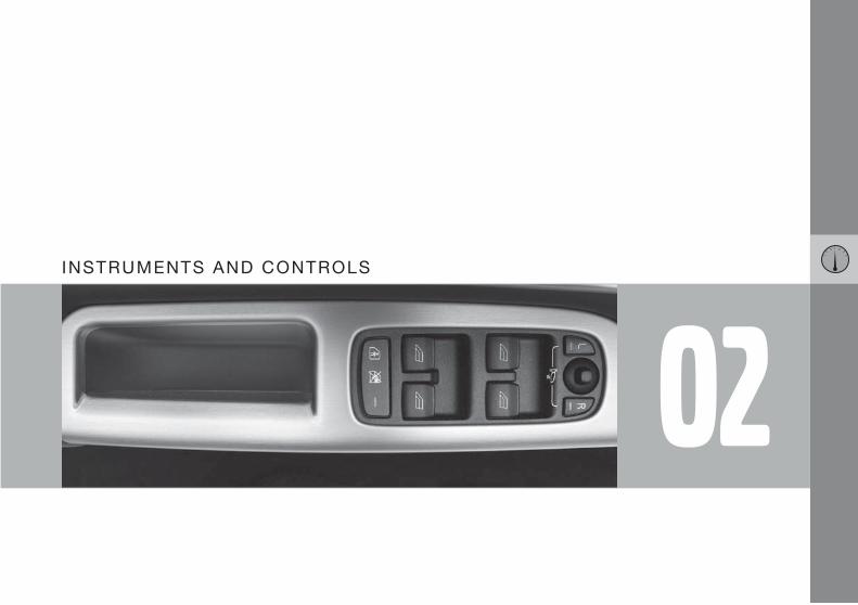
02INSTRUMENTS AND CONTROLS
02 Instruments and controls
Overview, left-hand drive car
02
40
G00
0000

02 Instruments and controls
Overview, left-hand drive car
02
41
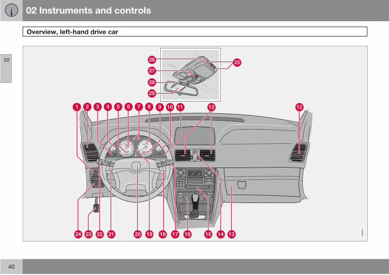
Lighting panel
Panel vents
Display
Temperature gauge
Odometer, trip meter, cruise control
Speedometer
Direction indicators
Tachometer
Outside temperature, clock, gear position
Fuel gauge
Indicator and warning symbols
Panel vents
Glovebox
Hazard warning flashers
Audio system
Climate control
Windscreen wipers
Keypad for phone/audio
Combined instrument panel
Horn
Cruise control
Direction indicators, dipped-main beam
switch, READ button
Parking brake
Parking brake release
Switches, reading lamps
Passenger compartment lighting
Sunroof control
Seatbelt reminder
Rearview mirror

02 Instruments and controls
Overview, right-hand drive car
02
42
G02
7038

02 Instruments and controls
Overview, right-hand drive car
02
43
Lighting panel
Panel vents
Indicator and warning symbols
Fuel gauge
Outside temperature, clock, gear position
Tachometer
Direction indicators
Speedometer
Odometer, trip meter, cruise control
Temperature gauge
Display
Panel vents
Glovebox
Hazard warning flashers
Audio system
Climate control
Direction indicators, dipped-main beam
switch, READ button
Parking brake
Cruise control
Horn
Combined instrument panel
Phone/Audio keypad
Windscreen wipers
Parking brake release
Switches, reading lamps
Passenger compartment lighting
Sunroof control
Seatbelt reminder
Rearview mirror
02 Instruments and controls
Driver's door control panel
02
44
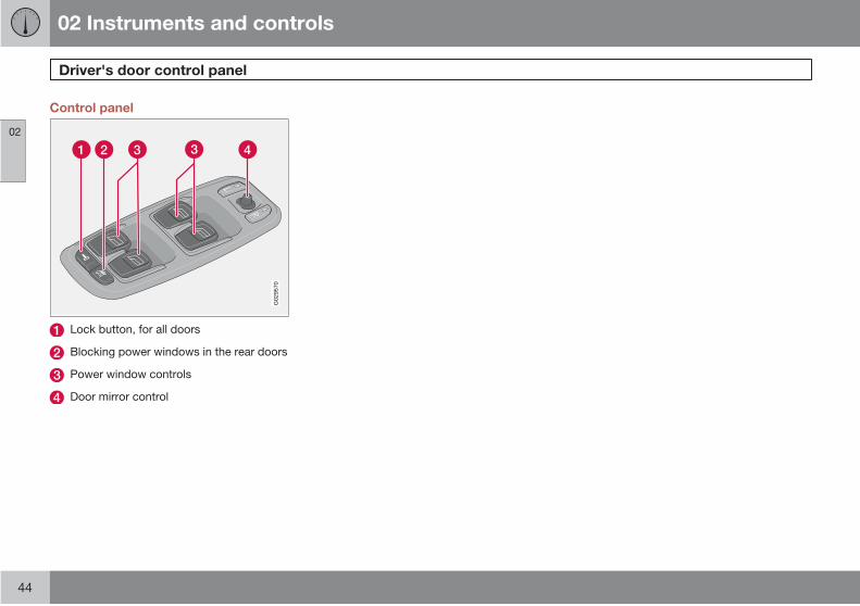
Control panel
G02
9570
Lock button, for all doors
Blocking power windows in the rear doors
Power window controls
Door mirror control
02 Instruments and controls
Combined instrument panel
02
45
G02
6973
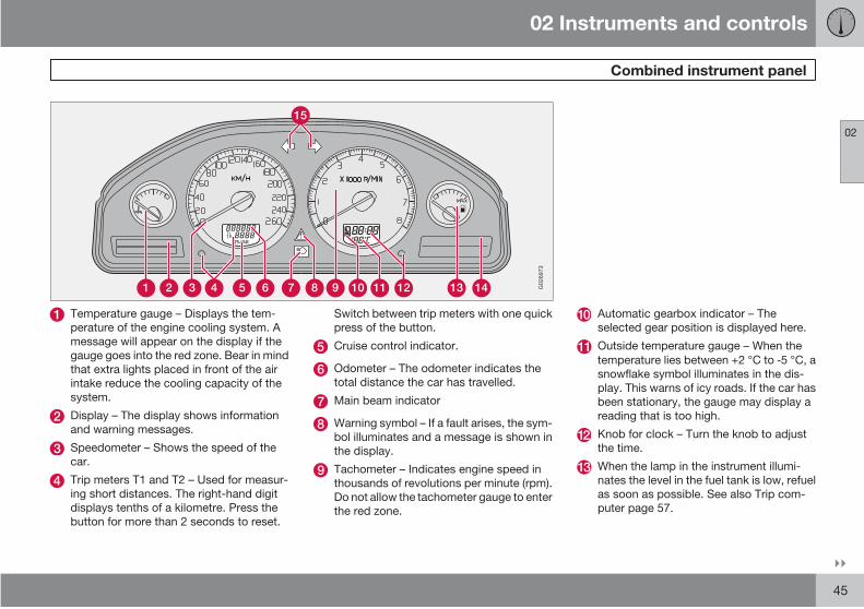
Temperature gauge – Displays the tem-
perature of the engine cooling system. A
message will appear on the display if the
gauge goes into the red zone. Bear in mind
that extra lights placed in front of the air
intake reduce the cooling capacity of the
system.
Display – The display shows information
and warning messages.
Speedometer – Shows the speed of the
car.
Trip meters T1 and T2 – Used for measur-
ing short distances. The right-hand digit
displays tenths of a kilometre. Press the
button for more than 2 seconds to reset.
Switch between trip meters with one quick
press of the button.
Cruise control indicator.
Odometer – The odometer indicates the
total distance the car has travelled.
Main beam indicator
Warning symbol – If a fault arises, the sym-
bol illuminates and a message is shown in
the display.
Tachometer – Indicates engine speed in
thousands of revolutions per minute (rpm).
Do not allow the tachometer gauge to enter
the red zone.
Automatic gearbox indicator – The
selected gear position is displayed here.
Outside temperature gauge – When the
temperature lies between +2 °C to 5 °C, a
snowflake symbol illuminates in the dis-
play. This warns of icy roads. If the car has
been stationary, the gauge may display a
reading that is too high.
Knob for clock – Turn the knob to adjust
the time.
When the lamp in the instrument illumi-
nates the level in the fuel tank is low, refuel
as soon as possible. See also Trip com-
puter page 57.

02 Instruments and controls
Combined instrument panel
02
46
Indicator and warning symbols
Direction indicators – left/right
02 Instruments and controls
Indicator and warning symbols
02
47
Functionality check, symbols
G02
6977
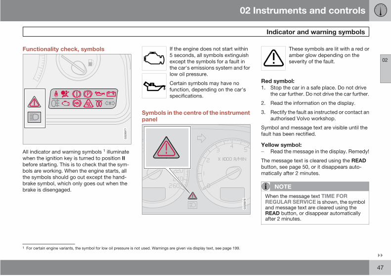
All indicator and warning symbols 1 illuminate
when the ignition key is turned to position II
before starting. This is to check that the sym-
bols are working. When the engine starts, all
the symbols should go out except the hand-
brake symbol, which only goes out when the
brake is disengaged.
If the engine does not start within
5 seconds, all symbols extinguish
except the symbols for a fault in
the car's emissions system and for
low oil pressure.
Certain symbols may have no
function, depending on the car's
specifications.
Symbols in the centre of the instrumentpanel
G02
6978
These symbols are lit with a red or
amber glow depending on the
severity of the fault.
Red symbol:1. Stop the car in a safe place. Do not drive
the car further. Do not drive the car further.
2. Read the information on the display.
3. Rectify the fault as instructed or contact an
authorised Volvo workshop.
Symbol and message text are visible until the
fault has been rectified.
Yellow symbol:Read the message in the display. Remedy!
The message text is cleared using the READ
button, see page 50, or it disappears auto-
matically after 2 minutes.
NOTE
When the message text TIME FORREGULAR SERVICE is shown, the symboland message text are cleared using theREAD button, or disappear automaticallyafter 2 minutes.
1 For certain engine variants, the symbol for low oil pressure is not used. Warnings are given via display text, see page 199.
02 Instruments and controls
Indicator and warning symbols
02
48
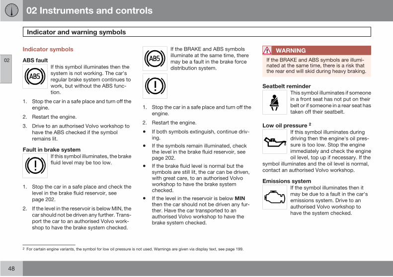
Indicator symbols
ABS faultIf this symbol illuminates then the
system is not working. The car's
regular brake system continues to
work, but without the ABS func-
tion.
1. Stop the car in a safe place and turn off the
engine.
2. Restart the engine.
3. Drive to an authorised Volvo workshop to
have the ABS checked if the symbol
remains lit.
Fault in brake systemIf this symbol illuminates, the brake
fluid level may be too low.
1. Stop the car in a safe place and check the
level in the brake fluid reservoir, see
page 202.
2. If the level in the reservoir is below MIN, the
car should not be driven any further. Trans-
port the car to an authorised Volvo work-
shop to have the brake system checked.
If the BRAKE and ABS symbols
illuminate at the same time, there
may be a fault in the brake force
distribution system.
1. Stop the car in a safe place and turn off the
engine.
2. Restart the engine.
• If both symbols extinguish, continue driv-ing.
• If the symbols remain illuminated, checkthe level in the brake fluid reservoir, seepage 202.
• If the brake fluid level is normal but thesymbols are still lit, the car can be driven,with great care, to an authorised Volvoworkshop to have the brake systemchecked.
• If the level in the reservoir is below MINthen the car should not be driven any fur-ther. Have the car transported to anauthorised Volvo workshop to have thebrake system checked.
WARNING
If the BRAKE and ABS symbols are illumi-nated at the same time, there is a risk thatthe rear end will skid during heavy braking.
Seatbelt reminderThis symbol illuminates if someone
in a front seat has not put on their
belt or if someone in a rear seat has
taken off their seatbelt.
Low oil pressure 2
If this symbol illuminates during
driving then the engine's oil pres-
sure is too low. Stop the engine
immediately and check the engine
oil level, top up if necessary. If the
symbol illuminates and the oil level is normal,
contact an authorised Volvo workshop.
Emissions systemIf the symbol illuminates then it
may be due to a fault in the car's
emissions system. Drive to an
authorised Volvo workshop to
have the system checked.
2 For certain engine variants, the symbol for low oil pressure is not used. Warnings are given via display text, see page 199.
02 Instruments and controls
Indicator and warning symbols
02
49
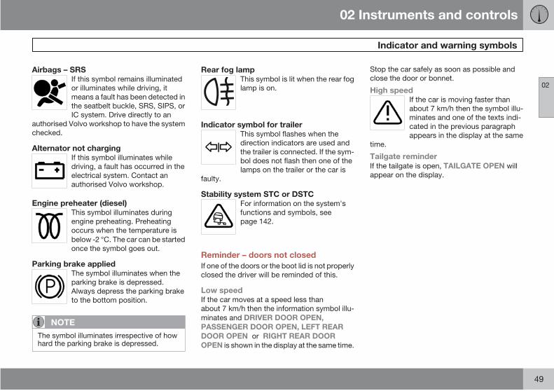
Airbags – SRSIf this symbol remains illuminated
or illuminates while driving, it
means a fault has been detected in
the seatbelt buckle, SRS, SIPS, or
IC system. Drive directly to an
authorised Volvo workshop to have the system
checked.
Alternator not chargingIf this symbol illuminates while
driving, a fault has occurred in the
electrical system. Contact an
authorised Volvo workshop.
Engine preheater (diesel)This symbol illuminates during
engine preheating. Preheating
occurs when the temperature is
below 2 °C. The car can be started
once the symbol goes out.
Parking brake appliedThe symbol illuminates when the
parking brake is depressed.
Always depress the parking brake
to the bottom position.
NOTE
The symbol illuminates irrespective of howhard the parking brake is depressed.
Rear fog lampThis symbol is lit when the rear fog
lamp is on.
Indicator symbol for trailerThis symbol flashes when the
direction indicators are used and
the trailer is connected. If the sym-
bol does not flash then one of the
lamps on the trailer or the car is
faulty.
Stability system STC or DSTCFor information on the system's
functions and symbols, see
page 142.
Reminder – doors not closed
If one of the doors or the boot lid is not properly
closed the driver will be reminded of this.
Low speedIf the car moves at a speed less than
about 7 km/h then the information symbol illu-
minates and DRIVER DOOR OPEN,
PASSENGER DOOR OPEN, LEFT REAR
DOOR OPEN or RIGHT REAR DOOR
OPEN is shown in the display at the same time.
Stop the car safely as soon as possible and
close the door or bonnet.
High speedIf the car is moving faster than
about 7 km/h then the symbol illu-
minates and one of the texts indi-
cated in the previous paragraph
appears in the display at the same
time.
Tailgate reminderIf the tailgate is open, TAILGATE OPEN will
appear on the display.
02 Instruments and controls
Information display
02
50
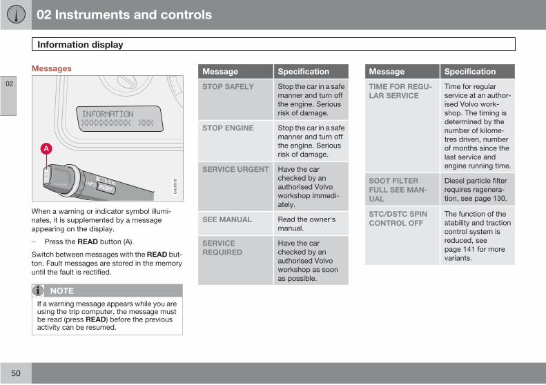
Messages
G02
6979
When a warning or indicator symbol illumi-
nates, it is supplemented by a message
appearing on the display.
Press the READ button (A).
Switch between messages with the READ but-
ton. Fault messages are stored in the memory
until the fault is rectified.
NOTE
If a warning message appears while you areusing the trip computer, the message mustbe read (press READ) before the previousactivity can be resumed.
Message Specification
STOP SAFELY Stop the car in a safe
manner and turn off
the engine. Serious
risk of damage.
STOP ENGINE Stop the car in a safe
manner and turn off
the engine. Serious
risk of damage.
SERVICE URGENT Have the car
checked by an
authorised Volvo
workshop immedi-
ately.
SEE MANUAL Read the owner's
manual.
SERVICE
REQUIRED
Have the car
checked by an
authorised Volvo
workshop as soon
as possible.
Message Specification
TIME FOR REGU-
LAR SERVICE
Time for regular
service at an author-
ised Volvo work-
shop. The timing is
determined by the
number of kilome-
tres driven, number
of months since the
last service and
engine running time.
SOOT FILTER
FULL SEE MAN-
UAL
Diesel particle filter
requires regenera-
tion, see page 130.
STC/DSTC SPIN
CONTROL OFF
The function of the
stability and traction
control system is
reduced, see
page 141 for more
variants.

02 Instruments and controls
Switches in the centre console
02
* Option/accessory, for more information, see Introduction. 51
Switch
G02
6944
NOTE
The order of the buttons may vary.
Air conditioning in the rear of the
passenger compartment*Press the button to activate the
air conditioning in the rear of
the passenger compartment.
Rear passenger compartment
air conditioning is deactivated
when the ignition is switched
off.
Child safety locks in the rear doors*Activating or deactivating the
electric child safety locks in the
rear doors. The ignition key
must be in position I or II. When
the child safety locks are acti-
vated, the lamp in the button
illuminates. A message is shown in the display
when the child safety locks are activated or
deactivated, see page 119.
Retractable power door mirrors*Used to fold in the door mirrors
if they are folded out or to fold
them out if they are folded in.
Proceed as follows if a door mirror has been
accidentally folded in or out:
1. Manually adjust the appropriate door mir-
ror to its normal position.
2. Turn the ignition key to position II.

02 Instruments and controls
Switches in the centre console
02
52 * Option/accessory, for more information, see Introduction.
3. Fold the door mirror inward and then out-
ward using the button.
The door mirrors have now returned to their
original fixed positions.
Park Assist*The system is always activated
when the car is started. Press
the button to deactivate/reacti-
vate the parking assistance
system. See also page 143.
Deactivation of the deadlocks* and
detectorsUse this button when you wish
to switch off the deadlock func-
tion (doors cannot be opened
from the inside when locked).
This button can also be used
when deactivating the alarm
system's movement and tilt detectors*. The
lamp illuminates when these systems are shut
down/deactivated, see pages 118 and 122.
Auxiliary lamps*Use this button to switch the
auxiliary lamps on with main
beam or to switch them off.
Active Bi-Xenon lights, ABL*The ABL headlamps' headlamp
pattern follows the movements
of the steering wheel during
driving. The function is acti-
vated automatically when the
car is started and can be deac-
tivated/activated by pressing the button. The
lamp in the button illuminates when the func-
tion is activated
Shifting headlamp pattern for right/left-
hand trafficHold the button depressed for at least 5 sec-
onds. The car must be stationary when the
headlamp pattern is shifted. The message
DIPPED BEAM SETT. F. RIGHT TRAFFIC or
DIPPED BEAM SETT. F. LEFT TRAFFIC is
shown in the display. For more information and
adapting headlamp pattern for halogen or Bi-
Xenon headlamps, see page 161.
Electric socket, (standard)/Cigarette
lighter*The electrical socket can be
used for 12 V accessories, such
as mobile phone chargers and
coolers.
The ignition key must be at least in position I
so that the socket can supply power.
The cigarette lighter is activated by pushing in
the button. The button pops out when the
lighter is hot. Pull out the lighter and light a cig-
arette on the heated coils. For safety reasons,
always keep the cover in place when the
socket is not in use. Maximum current tap 10 A.
WARNING
Always leave the plug in the socket whenthe socket is not in use.
BLIS - Blind Spot Information System*Press the button to deactivate
or reactivate the function. see
page 145 for further informa-
tion.

02 Instruments and controls
Switches in the centre console
02
53
Hazard warning flashers
1 2 3
4 5 6
7 8 9
ABC DEF
GHI JKL MNO
PQRS TUV WXYZ
0* #
POWER
VOLUMECDAM FM
G02
7096
Use the hazard warning flashers (all direction
indicators flash) when the car is stopped where
it could be a traffic hazard or obstruction. Press
the button to activate the function.
NOTE
Regulations regarding the use of hazardwarning flashers vary from country to coun-try.
Rear window and door mirror defrostersUse the defroster to quickly
remove misting and ice from
the rear window and the door
mirrors. Press the switch to
start defrosting the rear window
and door mirrors. The lamp in
the switch illuminates. The light
in the switch is lit Defrosting is
automatically disconnected
after about 12 minutes.
Heated front seatsFor heated front seats, see
page 84 or 86 for further
information.
02 Instruments and controls
Lighting panel
02
54 * Option/accessory, for more information, see Introduction.
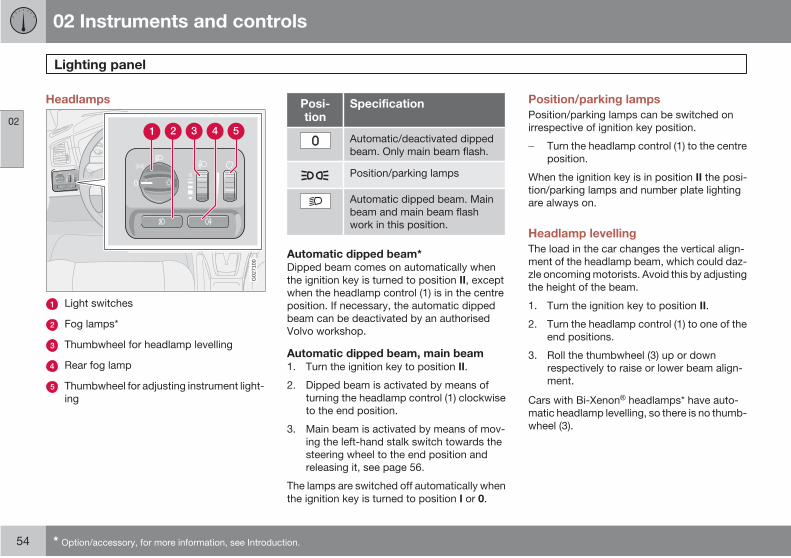
Headlamps
G02
7100
Light switches
Fog lamps*
Thumbwheel for headlamp levelling
Rear fog lamp
Thumbwheel for adjusting instrument light-
ing
Posi-tion
Specification
Automatic/deactivated dipped
beam. Only main beam flash.
Position/parking lamps
Automatic dipped beam. Main
beam and main beam flash
work in this position.
Automatic dipped beam*Dipped beam comes on automatically when
the ignition key is turned to position II, except
when the headlamp control (1) is in the centre
position. If necessary, the automatic dipped
beam can be deactivated by an authorised
Volvo workshop.
Automatic dipped beam, main beam1. Turn the ignition key to position II.
2. Dipped beam is activated by means of
turning the headlamp control (1) clockwise
to the end position.
3. Main beam is activated by means of mov-
ing the left-hand stalk switch towards the
steering wheel to the end position and
releasing it, see page 56.
The lamps are switched off automatically when
the ignition key is turned to position I or 0.
Position/parking lamps
Position/parking lamps can be switched on
irrespective of ignition key position.
Turn the headlamp control (1) to the centre
position.
When the ignition key is in position II the posi-
tion/parking lamps and number plate lighting
are always on.
Headlamp levelling
The load in the car changes the vertical align-
ment of the headlamp beam, which could daz-
zle oncoming motorists. Avoid this by adjusting
the height of the beam.
1. Turn the ignition key to position II.
2. Turn the headlamp control (1) to one of the
end positions.
3. Roll the thumbwheel (3) up or down
respectively to raise or lower beam align-
ment.
Cars with Bi-Xenon headlamps* have auto-
matic headlamp levelling, so there is no thumb-
wheel (3).
02 Instruments and controls
Lighting panel
02
* Option/accessory, for more information, see Introduction. 55
Instrument lighting
The instrument lighting is switched on when
the ignition key is in position II and the head-
lamp control (1) is in one of the end positions.
The lighting is automatically dimmed during the
day and can be controlled manually at night.
Roll the thumbwheel (5) up or down for brighter
or dimmer lighting.
Fog lamps
NOTE
Regulations for use of fog lamps vary fromcountry to country.
Fog lamps*The front fog lamps can be switched on along
with the headlamps or the position lamps/park-
ing lamps.
Press the button (2).
The light in the button illuminates when the
front fog lamps are switched on.
Rear fog lampThe rear fog lamp can only be switched on with
the headlamps or the front fog lamps.
Press the button (4).
The rear fog lamp indicator symbol on the com-
bined instrument panel and the light in the
button illuminate when the rear fog lamp is
switched on.
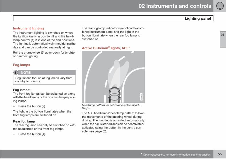
Active Bi-Xenon lights, ABL*
G02
0789
Headlamp pattern for active/non-active head-lamps.
The ABL headlamps' headlamp pattern follows
the movements of the steering wheel during
driving. The function is activated automatically
when the car is started and can be deactivated/
activated using the button in the centre con-
sole, see page 52.
02 Instruments and controls
Left-hand stalk switch
02
56
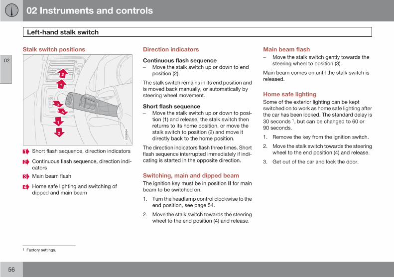
Stalk switch positions
G02
6954
Short flash sequence, direction indicators
Continuous flash sequence, direction indi-
cators
Main beam flash
Home safe lighting and switching of
dipped and main beam
Direction indicators
Continuous flash sequenceMove the stalk switch up or down to end
position (2).
The stalk switch remains in its end position and
is moved back manually, or automatically by
steering wheel movement.
Short flash sequenceMove the stalk switch up or down to posi-
tion (1) and release, the stalk switch then
returns to its home position, or move the
stalk switch to position (2) and move it
directly back to the home position.
The direction indicators flash three times. Short
flash sequence interrupted immediately if indi-
cating is started in the opposite direction.
Switching, main and dipped beam
The ignition key must be in position II for main
beam to be switched on.
1. Turn the headlamp control clockwise to the
end position, see page 54.
2. Move the stalk switch towards the steering
wheel to the end position (4) and release.
Main beam flash
Move the stalk switch gently towards the
steering wheel to position (3).
Main beam comes on until the stalk switch is
released.
Home safe lighting
Some of the exterior lighting can be kept
switched on to work as home safe lighting after
the car has been locked. The standard delay is
30 seconds 1, but can be changed to 60 or
90 seconds.
1. Remove the key from the ignition switch.
2. Move the stalk switch towards the steering
wheel to the end position (4) and release.
3. Get out of the car and lock the door.
1 Factory settings.

02 Instruments and controls
Trip computer*
02
* Option/accessory, for more information, see Introduction. 57
General information
G02
6956
READ - confirms
Thumbwheel - browse between menus
and options in the trip computer list
RESET - resets
ControlsTo scroll through trip computer information
turn the thumbwheel (B) either up or down in
steps. Continue turning to return to the starting
point.
NOTE
If a warning message interrupts while youare using the trip computer, this messagemust be acknowledged. Acknowledge bypressing the READ button and revert to thetrip computer function.
Functions
The trip computer displays the following infor-
mation:
• AVERAGE SPEED
• ACTUAL SPEED MPH*
• INSTANTANEOUS
• AVERAGE
• KILOMETRES TO EMPTY TANK
• DSTC, see page 141
Average speedWhen the ignition is switched off, the average
speed is stored and used as the basis of the
new value when you continue driving. Reset
using the RESET button.
Actual speed mph*Current speed is displayed in mph if the speed-
ometer is graduated in km/h. If it is graduated
in mph then the current speed is shown in mph.
InstantaneousCurrent fuel consumption is calculated every
second. The information on the display is
updated every couple of seconds. When the
car is stationary, " ----" appears on the display.
During the period for regeneration 1 fuel con-
sumption may increase, see page 130.
AverageThe average fuel consumption since the last
reset. Reset using RESET.
NOTE
There may be a slight error in the reading ifa fuel-driven parking heater* has been used.
Kilometres to empty tankThe calculation is based on the average fuel
consumption over the last 30 km and the
remaining driveable fuel quantity. The display
shows the approximate distance that can be
driven with the fuel quantity remaining in the
tank. No guaranteed range remains when the
display shows " --- kilometres to empty
tank". Refuel as soon as possible.
1 Only applies to diesel cars with particle filter.
02 Instruments and controls
Trip computer*
02
58 * Option/accessory, for more information, see Introduction.
NOTE
There may be a slight error in the reading ifa fuel-driven parking heater* has been usedor if driving style has been changed.
Resetting1. Select AVERAGE SPEED or AVERAGE
2. Press and hold the RESET button (C) for at
least five seconds to reset the average
speed and average consumption at the
same time.
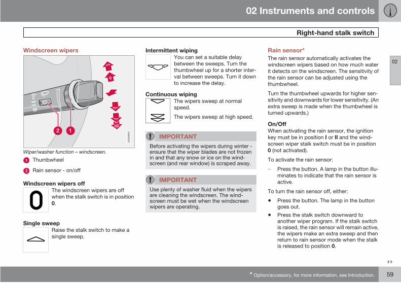
02 Instruments and controls
Right-hand stalk switch
02
* Option/accessory, for more information, see Introduction. 59
Windscreen wipers
G02
6953
Wiper/washer function – windscreen.
Thumbwheel
Rain sensor - on/off
Windscreen wipers offThe windscreen wipers are off
when the stalk switch is in position
0.
Single sweepRaise the stalk switch to make a
single sweep.
Intermittent wipingYou can set a suitable delay
between the sweeps. Turn the
thumbwheel up for a shorter inter-
val between sweeps. Turn it down
to increase the delay.
Continuous wipingThe wipers sweep at normal
speed.
The wipers sweep at high speed.
IMPORTANT
Before activating the wipers during winter -ensure that the wiper blades are not frozenin and that any snow or ice on the wind-screen (and rear window) is scraped away.
IMPORTANT
Use plenty of washer fluid when the wipersare cleaning the windscreen. The wind-screen must be wet when the windscreenwipers are operating.
Rain sensor*
The rain sensor automatically activates the
windscreen wipers based on how much water
it detects on the windscreen. The sensitivity of
the rain sensor can be adjusted using the
thumbwheel.
Turn the thumbwheel upwards for higher sen-
sitivity and downwards for lower sensitivity. (An
extra sweep is made when the thumbwheel is
turned upwards.)
On/OffWhen activating the rain sensor, the ignition
key must be in position I or II and the wind-
screen wiper stalk switch must be in position
0 (not activated).
To activate the rain sensor:
Press the button. A lamp in the button illu-
minates to indicate that the rain sensor is
active.
To turn the rain sensor off, either:
• Press the button. The lamp in the buttongoes out.
• Press the stalk switch downward toanother wiper program. If the stalk switchis raised, the rain sensor will remain active,the wipers make an extra sweep and thenreturn to rain sensor mode when the stalkis released to position 0.
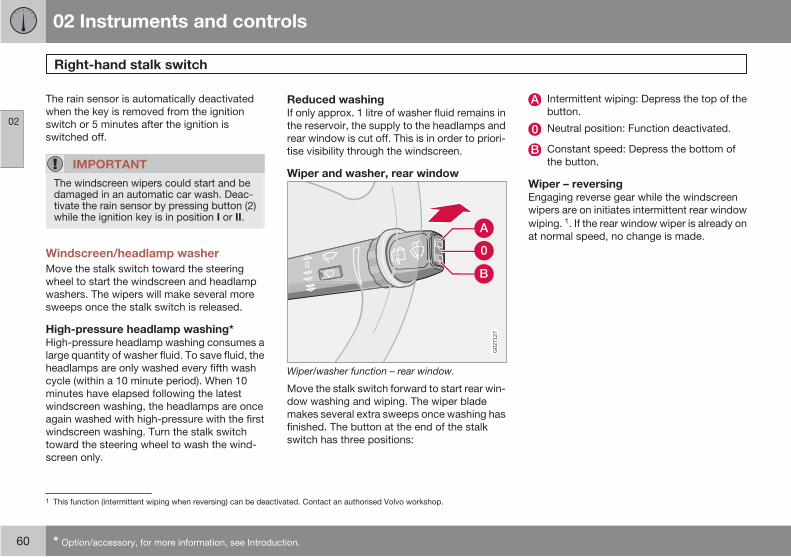
02 Instruments and controls
Right-hand stalk switch
02
60 * Option/accessory, for more information, see Introduction.
The rain sensor is automatically deactivated
when the key is removed from the ignition
switch or 5 minutes after the ignition is
switched off.
IMPORTANT
The windscreen wipers could start and bedamaged in an automatic car wash. Deac-tivate the rain sensor by pressing button (2)while the ignition key is in position I or II.
Windscreen/headlamp washer
Move the stalk switch toward the steering
wheel to start the windscreen and headlamp
washers. The wipers will make several more
sweeps once the stalk switch is released.
High-pressure headlamp washing*High-pressure headlamp washing consumes a
large quantity of washer fluid. To save fluid, the
headlamps are only washed every fifth wash
cycle (within a 10 minute period). When 10
minutes have elapsed following the latest
windscreen washing, the headlamps are once
again washed with high-pressure with the first
windscreen washing. Turn the stalk switch
toward the steering wheel to wash the wind-
screen only.
Reduced washingIf only approx. 1 litre of washer fluid remains in
the reservoir, the supply to the headlamps and
rear window is cut off. This is in order to priori-
tise visibility through the windscreen.
Wiper and washer, rear window
G02
7127
Wiper/washer function – rear window.
Move the stalk switch forward to start rear win-
dow washing and wiping. The wiper blade
makes several extra sweeps once washing has
finished. The button at the end of the stalk
switch has three positions:
Intermittent wiping: Depress the top of the
button.
Neutral position: Function deactivated.
Constant speed: Depress the bottom of
the button.
Wiper – reversingEngaging reverse gear while the windscreen
wipers are on initiates intermittent rear window
wiping. 1. If the rear window wiper is already on
at normal speed, no change is made.
1 This function (intermittent wiping when reversing) can be deactivated. Contact an authorised Volvo workshop.
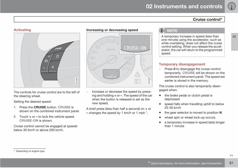
02 Instruments and controls
Cruise control*
02
* Option/accessory, for more information, see Introduction. 61
Activating
G02
7098
The controls for cruise control are to the left of
the steering wheel.
Setting the desired speed:
1. Press the CRUISE button. CRUISE is
shown on the combined instrument panel.
2. Touch + or – to lock the vehicle speed.
CRUISE-ON is shown.
Cruise control cannot be engaged at speeds
Increasing or decreasing speed
G02
6949
Increase or decrease the speed by press-
ing and holding + or –. The speed of the car
when the button is released is set as the
new speed.
A brief press (less than half a second) on + or
– changes the speed by 1 km/h or 1 mph 1.
NOTE
A temporary increase in speed (less thanone minute) using the accelerator, such aswhile overtaking, does not affect the cruisecontrol setting. When you release the accel-erator, the car will return to the programmedspeed.
Temporary disengagement
Press 0 to disengage the cruise control
temporarily. CRUISE will be shown on the
combined instrument panel. The speed set
earlier is stored in the memory.
The cruise control is also temporarily disen-
gaged when:
• the brake pedal or clutch pedal isdepressed
• speed falls when travelling uphill to below25-30 km/h
• the gear selector is moved to position N
• wheel spin or wheel lock-up occurs.
• a temporary increase in speed lasts longerthan 1 minute
1 Depending on engine type.
below 30 km/h or above 200 km/h.
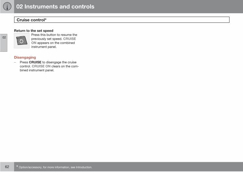
02 Instruments and controls
Cruise control*
02
62 * Option/accessory, for more information, see Introduction.
Return to the set speedPress this button to resume the
previously set speed. CRUISE
ON appears on the combined
instrument panel.
Disengaging
Press CRUISE to disengage the cruise
control. CRUISE ON clears on the com-
bined instrument panel.
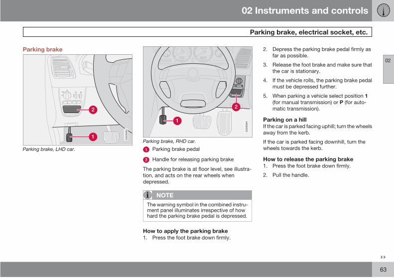
02 Instruments and controls
Parking brake, electrical socket, etc.
02
63
Parking brake
G02
6992
Parking brake, LHD car.
G02
6994
Parking brake, RHD car.
Parking brake pedal
Handle for releasing parking brake
The parking brake is at floor level, see illustra-
tion, and acts on the rear wheels when
depressed.
NOTE
The warning symbol in the combined instru-ment panel illuminates irrespective of howhard the parking brake pedal is depressed.
How to apply the parking brake1. Press the foot brake down firmly.
2. Depress the parking brake pedal firmly as
far as possible.
3. Release the foot brake and make sure that
the car is stationary.
4. If the vehicle rolls, the parking brake pedal
must be depressed further.
5. When parking a vehicle select position 1
(for manual transmission) or P (for auto-
matic transmission).
Parking on a hillIf the car is parked facing uphill; turn the wheels
away from the kerb.
If the car is parked facing downhill, turn the
wheels towards the kerb.
How to release the parking brake1. Press the foot brake down firmly.
2. Pull the handle.

02 Instruments and controls
Parking brake, electrical socket, etc.
02
64
Electrical socket in the rear seat
G02
8425
The electrical socket can be used for various
accessories, such as mobile phone chargers
and coolers. It is designed for 12 V. The maxi-
mum current is 10 A. For the socket to supply
current, the ignition key must be in at least
position I.
Steering wheel adjustment
G02
6999
The steering wheel can be adjusted for both
height and reach. Press down the control on
the left-hand side of the steering column. Then
adjust the steering wheel to the position that
suits you best. Press the control back into
place to lock the steering wheel. If this is diffi-
cult, press the steering wheel slightly while
pressing the control back.
WARNING
Adjust the steering wheel before driving off,never while driving. Check that the steeringwheel is fixed in position.
Opening the tailgate
G02
7005
Open the tailgate by pulling the handle indi-
cated in the illustration. Fold down the rear flap
by lifting the handle up.
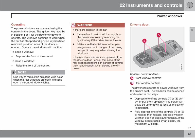
02 Instruments and controls
Power windows
02
65
Operating
The power windows are operated using the
controls in the doors. The ignition key must be
in position I or II for the power windows to
operate. The windows continue to work when
the car has stopped and ignition key has been
removed, provided none of the doors is
opened. Operate the windows with caution.
To open a window:
Depress the front of the control.
To close a window:
Raise the front of the control.
NOTE
One way to reduce the pulsating wind noisewhen the rear windows are open is to alsoopen the front windows slightly.
WARNING
If there are children in the car:
• Remember to switch off the supply tothe power windows by removing theignition key if the driver leaves the car.
• Make sure that children or other pas-sengers are not in danger of becomingtrapped in any way when closing thewindows.
If the rear door windows are operated fromthe driver's door - check that none of therear seat passengers is in danger of gettingtheir hands caught when closing the win-dows.
Driver's door
G02
9571
Controls, power windows.
Front window controls
Rear window controls
The driver can operate all power windows from
the driver's seat. The windows can be opened
and closed in two ways:
• Depress one of the controls (A) or (B) gen-tly, or pull them up gently. The power win-dows go up or down as long as the switchis actuated.
• Fully depress one of the controls (A) or (B)or raise it, then release. The side windowwill then open or close automatically. If thewindow is obstructed by an object, themovement will stop.
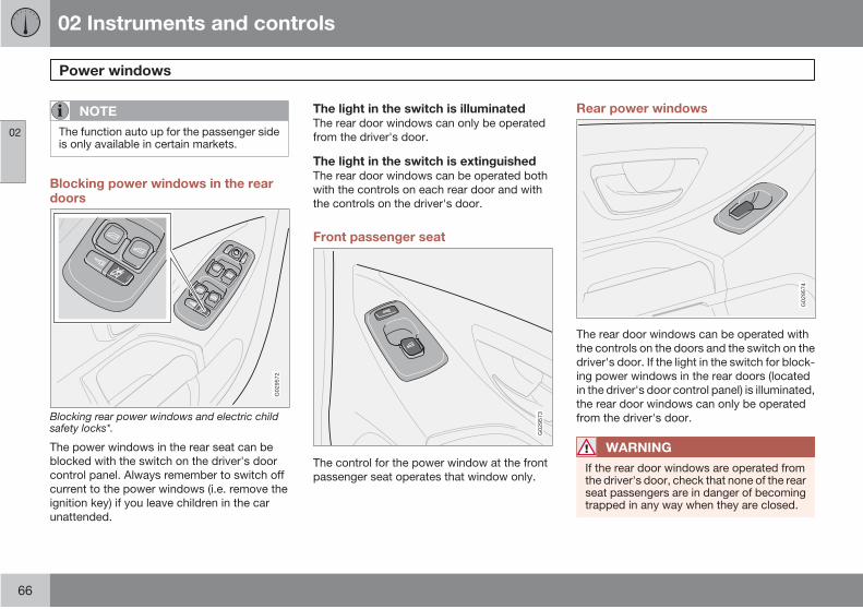
02 Instruments and controls
Power windows
02
66
NOTE
The function auto up for the passenger sideis only available in certain markets.
Blocking power windows in the reardoors
G02
9572
Blocking rear power windows and electric childsafety locks*.
The power windows in the rear seat can be
blocked with the switch on the driver's door
control panel. Always remember to switch off
current to the power windows (i.e. remove the
ignition key) if you leave children in the car
unattended.
The light in the switch is illuminatedThe rear door windows can only be operated
from the driver's door.
The light in the switch is extinguishedThe rear door windows can be operated both
with the controls on each rear door and with
the controls on the driver's door.
Front passenger seat
G02
9573
The control for the power window at the front
passenger seat operates that window only.
Rear power windows
G02
9574
The rear door windows can be operated with
the controls on the doors and the switch on the
driver's door. If the light in the switch for block-
ing power windows in the rear doors (located
in the driver's door control panel) is illuminated,
the rear door windows can only be operated
from the driver's door.
WARNING
If the rear door windows are operated fromthe driver's door, check that none of the rearseat passengers are in danger of becomingtrapped in any way when they are closed.
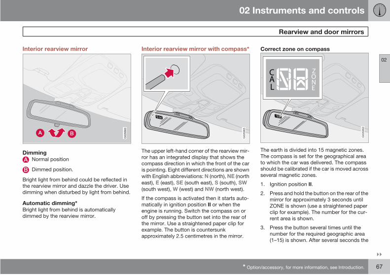
02 Instruments and controls
Rearview and door mirrors
02
* Option/accessory, for more information, see Introduction. 67
Interior rearview mirror
G02
6660
DimmingNormal position
Dimmed position.
Bright light from behind could be reflected in
the rearview mirror and dazzle the driver. Use
dimming when disturbed by light from behind.
Automatic dimming*Bright light from behind is automatically
dimmed by the rearview mirror.
Interior rearview mirror with compass*
G02
6965
The upper left-hand corner of the rearview mir-
ror has an integrated display that shows the
compass direction in which the front of the car
is pointing. Eight different directions are shown
with English abbreviations: N (north), NE (north
east), E (east), SE (south east), S (south), SW
(south west), W (west) and NW (north west).
If the compass is activated then it starts auto-
matically in ignition position II or when the
engine is running. Switch the compass on or
off by pressing the button set into the rear of
the mirror. Use a straightened paper clip for
example. The button is countersunk
approximately 2.5 centimetres in the mirror.
Correct zone on compass
CAL
ZONE
CAL
ZONE
G02
6950
The earth is divided into 15 magnetic zones.
The compass is set for the geographical area
to which the car was delivered. The compass
should be calibrated if the car is moved across
several magnetic zones.
1. Ignition position II.
2. Press and hold the button on the rear of the
mirror for approximately 3 seconds until
ZONE is shown (use a straightened paper
clip for example). The number for the cur-
rent area is shown.
3. Press the button several times until the
number for the required geographic area
(1–15) is shown. After several seconds the
02 Instruments and controls
Rearview and door mirrors
02
68
display returns to show the compass direc-
tion, this means that the change of zone is
complete.
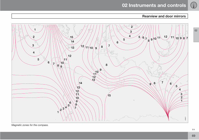
02 Instruments and controls
Rearview and door mirrors
02
69
G02
6677
Magnetic zones for the compass.
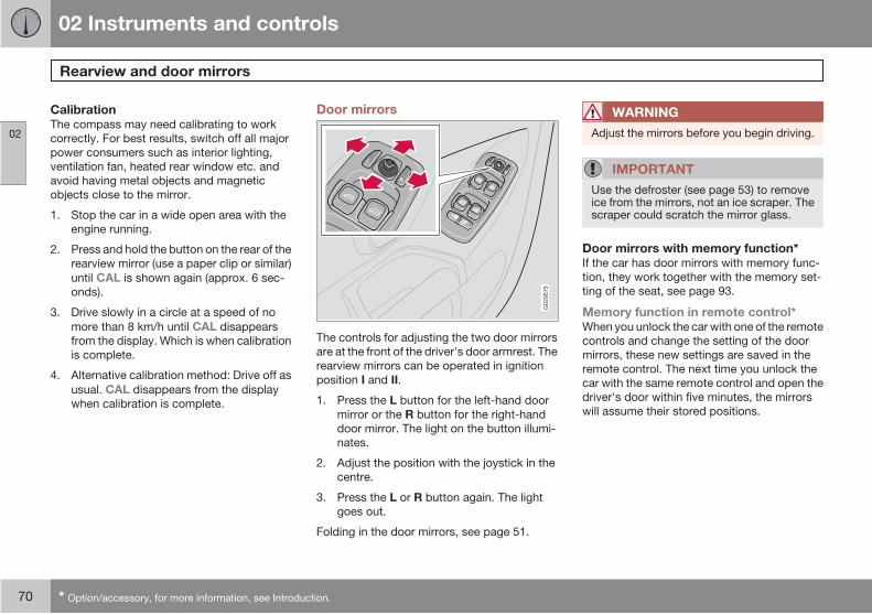
02 Instruments and controls
Rearview and door mirrors
02
70 * Option/accessory, for more information, see Introduction.
CalibrationThe compass may need calibrating to work
correctly. For best results, switch off all major
power consumers such as interior lighting,
ventilation fan, heated rear window etc. and
avoid having metal objects and magnetic
objects close to the mirror.
1. Stop the car in a wide open area with the
engine running.
2. Press and hold the button on the rear of the
rearview mirror (use a paper clip or similar)
until CAL is shown again (approx. 6 sec-
onds).
3. Drive slowly in a circle at a speed of no
more than 8 km/h until CAL disappears
from the display. Which is when calibration
is complete.
4. Alternative calibration method: Drive off as
usual. CAL disappears from the display
when calibration is complete.
Door mirrors
G02
9575
The controls for adjusting the two door mirrors
are at the front of the driver's door armrest. The
rearview mirrors can be operated in ignition
position I and II.
1. Press the L button for the left-hand door
mirror or the R button for the right-hand
door mirror. The light on the button illumi-
nates.
2. Adjust the position with the joystick in the
centre.
3. Press the L or R button again. The light
goes out.
Folding in the door mirrors, see page 51.
WARNING
Adjust the mirrors before you begin driving.
IMPORTANT
Use the defroster (see page 53) to removeice from the mirrors, not an ice scraper. Thescraper could scratch the mirror glass.
Door mirrors with memory function*If the car has door mirrors with memory func-
tion, they work together with the memory set-
ting of the seat, see page 93.
Memory function in remote control*When you unlock the car with one of the remote
controls and change the setting of the door
mirrors, these new settings are saved in the
remote control. The next time you unlock the
car with the same remote control and open the
driver's door within five minutes, the mirrors
will assume their stored positions.
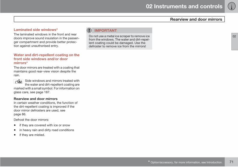
02 Instruments and controls
Rearview and door mirrors
02
* Option/accessory, for more information, see Introduction. 71
Laminated side windows*
The laminated windows in the front and rear
doors improve sound insulation in the passen-
ger compartment and provide better protec-
tion against unauthorised entry.
Water and dirt-repellent coating on thefront side windows and/or doormirrors*
The door mirrors are treated with a coating that
maintains good rear-view vision despite the
rain.
Side windows and mirrors treated with
the water and dirt-repellent coating are
marked with a small symbol. For information on
glass care, see page 187.
Rearview and door mirrorsIn certain weather conditions, the function of
the dirt-repellent coating is improved if the
door mirror defrosters are used, see
page 86.
Defrost the door mirrors:
• if they are covered with ice or snow
• in heavy rain and dirty road conditions
• if they are misted.
IMPORTANT
Do not use a metal ice scraper to remove icefrom the windows. The water and dirt-repel-lent coating could be damaged. Use thedefroster to remove ice from the mirrors!

02 Instruments and controls
Power sunroof*
02
72 * Option/accessory, for more information, see Introduction.
Open positions
G00
7503
The sunroof controls are located in the roof
panel. The sunroof can be opened in two posi-
tions:
Ventilation position, up at the rear edge
Sliding position, backwards/forwards
The ignition key must be in position I or II.
WARNING
If there are children in the car:
Switch off the supply to the power sunroofby removing the ignition key if the driverleaves the car.
G02
7010
Closing, automatic
Closing, manual
Opening, manual
Opening, automatic
Opening, ventilation position
Closing, ventilation position
Ventilation positionTo open:
Press the rear edge of the control (5)
upward.
To close:
Pull the rear edge of the control (6) down-
ward.
Switch from ventilation position to comfort
position; pull the control rearwards to its end
position (4) and release.
Automatic operationMove the control over the resistance point
position (3) to the rearmost end position (4) or
over the resistance point position (2) to the
front end position (1) and release. The sunroof
will open to the comfort position or will close
completely.
In order to open from comfort position to maxi-
mum opening:
Pull the control to the rear once more to the
end position (4) and release.
Manual operationTo open:
Pull the control rearward to the point of
resistance (3). The sunroof moves toward
the fully open position as long as the button
is held in this position.
To close:
Press the control forward to the point of
resistance (2). The sunroof moves toward
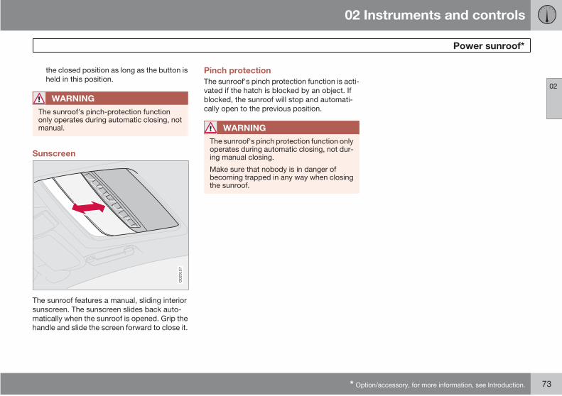
02 Instruments and controls
Power sunroof*
02
* Option/accessory, for more information, see Introduction. 73
the closed position as long as the button is
held in this position.
WARNING
The sunroof's pinch-protection functiononly operates during automatic closing, notmanual.
Sunscreen
G02
0157
The sunroof features a manual, sliding interior
sunscreen. The sunscreen slides back auto-
matically when the sunroof is opened. Grip the
handle and slide the screen forward to close it.
Pinch protection
The sunroof's pinch protection function is acti-
vated if the hatch is blocked by an object. If
blocked, the sunroof will stop and automati-
cally open to the previous position.
WARNING
The sunroof's pinch protection function onlyoperates during automatic closing, not dur-ing manual closing.
Make sure that nobody is in danger ofbecoming trapped in any way when closingthe sunroof.

02 Instruments and controls
HomeLink EU*
02
74 * Option/accessory, for more information, see Introduction.
General
G03
0070
HomeLink is a programmable remote control
which can control up to three different devices
(e.g. garage door, alarm system, outdoor light-
ing and indoor lighting etc.) and in doing so
replace their remote controls. HomeLink is
supplied built into the left-hand sun visor.
HomeLink's panel consists of three program-
mable buttons and one indicator lamp.
NOTE
HomeLink is designed to be inoperable ifthe car is locked from the outside.
Save the original remote controls for futureprogramming (e.g. for purchasing a newcar).
Erase the programming for the buttonswhen selling the car.
Metallic sun visors should not be used incars equipped with HomeLink. This couldhave a negative effect on the HomeLinkfunction.
OperationWhen HomeLink is fully programmed it can be
used in place of the separate original remote
controls.
Press the programmed button to activate the
garage door, alarm system etc. The indicator
lamp illuminates for the time that the button is
kept depressed.
NOTE
In the event that the ignition is not activated,HomeLink operates for 30 minutes after thedriver's door has been opened.
The original remote controls can of course be
used in parallel with HomeLink.
WARNING
If HomeLink is used to operate a garagedoor or gate, ensure that nobody is in thevicinity of the door or gate while it is inmotion.
Do not use the HomeLink remote control forany garage door that does not have safetystop and safety reverse. The garage doormust react immediately when it detects thatsomething is preventing its movement, andstop directly and reverse. A garage doorwithout these characteristics could causepersonal injury. For further information, ringthe HomeLink Hotline: 008000 466 354 65(free of charge). They can also be contactedvia the Internet: www.homelink.com.
Programming for the first timeThe first step erases the memory in HomeLink
and must not be carried out when only one
individual button is being reprogrammed.
1. Depress the two outer buttons and do not
release until the indicator lamp starts to
flash after approx. 20 seconds. The flash-
ing indicates that HomeLink is set in "learn
mode" and is ready to be programmed.
2. Position the original remote control 2-8 cm
from HomeLink. Monitor the indicator
lamp.
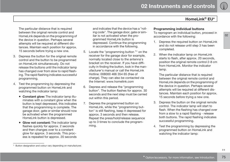
02 Instruments and controls
HomeLink EU*
02
* Option/accessory, for more information, see Introduction. 75
The particular distance that is required
between the original remote control and
HomeLink depends on the programming of
the device in question. Perhaps several
attempts will be required at different dis-
tances. Maintain each position for approx.
15 seconds before trying a new one.
3. Depress the button for the original remote
control and the button to be programmed
on HomeLink simultaneously. Do not
release the buttons until the indicator lamp
has changed over from slow to rapid flash-
ing. The rapid flashing indicates successful
programming.
4. Test the programming by depressing the
programmed button on HomeLink and
watching the indicator lamp:
• Constant glow: The indicator lamp illu-minates with a constant glow when thebutton is kept depressed, this indicatesthat the programming is complete. Thegarage door, gate or similar should nowbe activated when the programmedHomeLink button is depressed.
• Glow not constant: The indicator lampflashes quickly for approx. 2 secondsand then changes over to a constantglow for approx. 3 seconds. This proc-ess is repeated for approx. 20 seconds
and indicates that the device has a "roll-ing code". The garage door, gate or sim-ilar is not activated when the pro-grammed HomeLink button isdepressed. Continue the programmingin accordance with the following.
5. Locate the "programming button 1" on the
receiver for the garage door for example,
normally located close to the antenna's
bracket on the receiver. If you have diffi-
culty in finding the button, look in the man-
ufacturer's manual or call the HomeLink
Hotline: 008000 466 354 65 (free of
charge). They can also be contacted via
the Internet: www.homelink.com
6. Depress and release the "programming
button". The button flashes for approx. 30
seconds and the next step must be carried
out within this period.
7. Depress the programmed button on
HomeLink, while the "programming but-
ton" is still flashing, keep it depressed for
approx. 3 seconds and then release.
Repeat the press/hold/release sequence
up to 3 times to conclude the program-
ming.
Programming individual buttonsTo reprogram an individual button, proceed in
accordance with the following:
1. Depress the required button on HomeLink
and do not release until step 3 has been
completed.
2. When the indicator lamp on HomeLink
starts to flash, after approx. 20 seconds,
position the original remote control 2-8 cm
from HomeLink. Monitor the indicator
lamp.
The particular distance that is required
between the original remote control and
HomeLink depends on the programming of
the device in question. Perhaps several
attempts will be required at different dis-
tances. Maintain each position for approx.
15 seconds before trying a new one.
3. Depress the button on the original remote
control. The indicator lamp will start to
flash. When the flashing has changed over
from a slow to a rapid flashing - release
both buttons. The rapid flashing indicates
successful programming.
4. Test the programming by depressing the
programmed button on HomeLink and
watching the indicator lamp:
1 Button designation and colour vary depending on manufacturer.
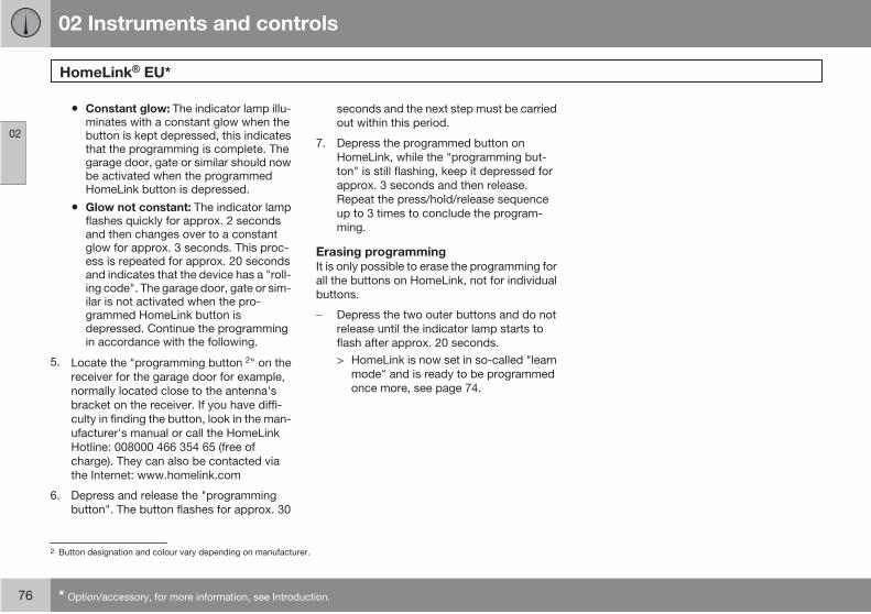
02 Instruments and controls
HomeLink EU*
02
76 * Option/accessory, for more information, see Introduction.
• Constant glow: The indicator lamp illu-minates with a constant glow when thebutton is kept depressed, this indicatesthat the programming is complete. Thegarage door, gate or similar should nowbe activated when the programmedHomeLink button is depressed.
• Glow not constant: The indicator lampflashes quickly for approx. 2 secondsand then changes over to a constantglow for approx. 3 seconds. This proc-ess is repeated for approx. 20 secondsand indicates that the device has a "roll-ing code". The garage door, gate or sim-ilar is not activated when the pro-grammed HomeLink button isdepressed. Continue the programmingin accordance with the following.
5. Locate the "programming button 2" on the
receiver for the garage door for example,
normally located close to the antenna's
bracket on the receiver. If you have diffi-
culty in finding the button, look in the man-
ufacturer's manual or call the HomeLink
Hotline: 008000 466 354 65 (free of
charge). They can also be contacted via
the Internet: www.homelink.com
6. Depress and release the "programming
button". The button flashes for approx. 30
seconds and the next step must be carried
out within this period.
7. Depress the programmed button on
HomeLink, while the "programming but-
ton" is still flashing, keep it depressed for
approx. 3 seconds and then release.
Repeat the press/hold/release sequence
up to 3 times to conclude the program-
ming.
Erasing programmingIt is only possible to erase the programming for
all the buttons on HomeLink, not for individual
buttons.
Depress the two outer buttons and do not
release until the indicator lamp starts to
flash after approx. 20 seconds.
> HomeLink is now set in so-called "learn
mode" and is ready to be programmed
once more, see page 74.
2 Button designation and colour vary depending on manufacturer.
02 Instruments and controls
02
77

G02
0906
78 * Option/accessory, for more information, see Introduction.
General information on climate control................................................... 80
Electronic Climate Control, ECC............................................................. 84
Fuel-driven parking heater*..................................................................... 87

03CLIMATE CONTROL
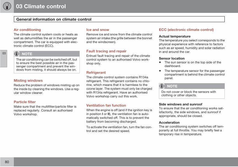
03 Climate control
General information on climate control
03
80
Air conditioning
The climate control system cools or heats as
well as dehumidifies the air in the passenger
compartment. The car is equipped with elec-
tronic climate control (ECC).
NOTE
The air conditioning can be switched off, butto ensure the best possible air in the pas-senger compartment and prevent the win-dows from misting, it should always be on.
Misting windows
Reduce the problem of windows misting up on
the inside by cleaning the windows. Use a reg-
ular window cleaner.
Particle filter
Make sure that the multifilter/particle filter is
replaced regularly. Consult an authorised
Volvo workshop.
Ice and snow
Remove ice and snow from the climate control
system air intake (the grille between the bonnet
and the windscreen).
Fault tracing and repair
Entrust fault tracing and repair of the climate
control system to an authorised Volvo work-
shop only.
Refrigerant
The climate control system contains R134a
refrigerant. This refrigerant contains no chlo-
rine, which means that it is harmless to the
ozone layer. The system must only be charged
with R134a refrigerant. Have an authorised
Volvo workshop carry out this work.
Ventilation fan function
When the engine is off (and if the ignition key is
in position I or II), the ventilation fan is auto-
matically switched off. This is to prevent the
battery from becoming discharged.
To activate the ventilation fan, turn the fan con-
trol and set the desired speed.
ECC (electronic climate control)
Actual temperatureThe temperature you select corresponds to the
physical experience with reference to factors
such as air speed, humidity and solar radiation
in and around the car.
Sensor location
• The sun sensor is on the top side of thedashboard.
• The temperature sensor for the passengercompartment is behind the climate controlpanel.
NOTE
Do not cover or block the sensors withclothing or other objects.
Side windows and sunroofTo ensure that the air conditioning works sat-
isfactorily, the side windows, and sunroof if
appropriate, should be closed.
AccelerationThe air conditioning system switches off tem-
porarily at full throttle. You may briefly feel a
temporary rise in temperature.
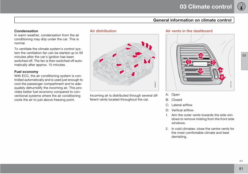
03 Climate control
General information on climate control
03
81
CondensationIn warm weather, condensation from the air
conditioning may drip under the car. This is
normal.
To ventilate the climate system's control sys-
tem the ventilation fan can be started up to 50
minutes after the car's ignition has been
switched off. The fan is then switched off auto-
matically after approx. 15 minutes.
Fuel economyWith ECC, the air conditioning system is con-
trolled automatically and is used just enough to
cool the passenger compartment and to ade-
quately dehumidify the incoming air. This pro-
vides better fuel economy compared to con-
ventional systems where the air conditioning
cools the air to just above freezing point.
Air distribution
G02
8577
Incoming air is distributed through several dif-
ferent vents located throughout the car.
Air vents in the dashboard
G02
7043
A: Open
B: Closed
C: Lateral airflow
D: Vertical airflow.
1. Aim the outer vents towards the side win-
dows to remove misting from the front side
windows.
2. In cold climates: close the centre vents for
the most comfortable climate and best
demisting.
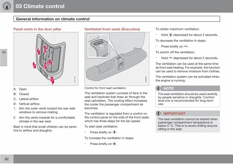
03 Climate control
General information on climate control
03
82
Panel vents in the door pillar
0
G02
7064
A: Open
B: Closed
C: Lateral airflow
D: Vertical airflow.
1. Aim the outer vents toward the rear side
windows to remove misting.
2. Aim the vents inwards for a comfortable
climate in the rear seat.
Bear in mind that small children can be sensi-
tive to airflow and draughts.
Ventilated front seats (Executive)
G03
0244
Control for front seat ventilation.
The ventilation system consists of fans in the
seat and backrest that draw air through the
seat upholstery. The cooling effect increases
the cooler the passenger compartment air
becomes.
The ventilation is regulated from a control on
the control panel on the side of the front seats
which has three steps for the fan speed.
To start seat ventilation:
Press briefly on .
To increase the ventilation in steps:
Press briefly on .
To obtain maximum ventilation:
Hold depressed for about 2 seconds.
To decrease the ventilation in steps:
Press briefly on .
To switch off the ventilation:
Hold depressed for about 2 seconds.
The ventilation can be used at the same time
as front seat heating. For example, the function
can be used to remove moisture from clothes.
The ventilation system can be activated when
the engine is running.
NOTE
The seat ventilation should be used carefullyby people sensitive to draughts. Comfortlevel one is recommended for long-termuse.
IMPORTANT
The seat ventilation cannot be started whenpassenger compartment temperature isbelow 5 °C. This is to avoid chilling anyonesitting in the seat.
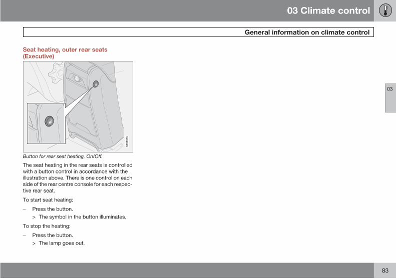
03 Climate control
General information on climate control
03
83
Seat heating, outer rear seats(Executive)
G03
0976
Button for rear seat heating, On/Off.
The seat heating in the rear seats is controlled
with a button control in accordance with the
illustration above. There is one control on each
side of the rear centre console for each respec-
tive rear seat.
To start seat heating:
Press the button.
> The symbol in the button illuminates.
To stop the heating:
Press the button.
> The lamp goes out.
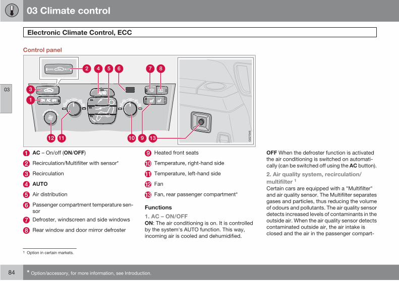
03 Climate control
Electronic Climate Control, ECC
03
84 * Option/accessory, for more information, see Introduction.
Control panel
G02
7046
AC – On/off (ON/OFF)
Recirculation/Multifilter with sensor*
Recirculation
AUTO
Air distribution
Passenger compartment temperature sen-
sor
Defroster, windscreen and side windows
Rear window and door mirror defroster
Heated front seats
Temperature, right-hand side
Temperature, left-hand side
Fan
Fan, rear passenger compartment*
Functions
1. AC – ON/OFFON: The air conditioning is on. It is controlled
by the system's AUTO function. This way,
incoming air is cooled and dehumidified.
OFF When the defroster function is activated
the air conditioning is switched on automati-
cally (can be switched off using the AC button).
2. Air quality system, recirculation/
multifilter 1
Certain cars are equipped with a "Multifilter"
and air quality sensor. The Multifilter separates
gases and particles, thus reducing the volume
of odours and pollutants. The air quality sensor
detects increased levels of contaminants in the
outside air. When the air quality sensor detects
contaminated outside air, the air intake is
closed and the air in the passenger compart-
1 Option in certain markets.

03 Climate control
Electronic Climate Control, ECC
03
85
ment is recirculated. The Multifilter also cleans
the air recirculating in the passenger compart-
ment.
A green light (AUT) illuminates
in the button when the air qual-
ity sensor is active.AUTMAN
Operation:
Press AUTO to activate the air quality sensor
(normal setting).
Or:
Select one of the following three functions
by repeatedly pressing .
• The lamp for MAN illuminates. Recircula-tion is now activated.
• No lamp illuminates. Recirculation is notactivated unless needed to cool in a warmclimate.
• The lamp for AUT illuminates. Recircula-tion is now activated.
Keep the following in mind:
• Make it a rule to have the air quality sensoractivated at all times.
• Recirculation is limited in cold weather toavoid misting.
• If misting occurs, you should deactivatethe air quality sensor.
• If misting occurs, you can use the defrosterfunctions for the windscreen, side win-dows and rear window.
• Follow the Volvo service programme forthe recommended replacement interval ofthe Multifilter. If the car is used in environ-ments where more contaminants are pres-ent, it may be necessary to change theMultifilter more often.
3. RecirculationRecirculation can be used to shut out bad air,
exhaust, etc. from the passenger compart-
ment. The air in the passenger compartment is
recirculated, i.e. no outside air is taken into the
car when this function is activated.
If you allow the air in the car to recirculate, there
is a risk of icing and misting, especially in win-
ter.
The timer function (cars with Multifilter and air
quality sensor have no timer function) mini-
mises the risk for ice, misting and bad air.
Activate the function as follows:
1. Press for more than 3 seconds. The
lamp flashes for 5 seconds. The air recir-
culates in the car for 3 – 12 minutes
depending on the outside temperature.
2. The timer function is activated each time
you press .
To switch off the timer function:
Press again for more than 3 sec-
onds. The lamp illuminates for 5 seconds
to confirm your selection.
4. AUTOThe AUTO function automatically regulates cli-
mate control and maintains the selected tem-
perature. The automatic function controls
heating, air conditioning, air quality sensor, fan
speed, recirculation and air distribution. If you
select one or more manual functions, the other
functions continue to be controlled automati-
cally. All manual settings are switched off when
AUTO is switched on.
5. Air distribution
• When the top button is depressed, air isdirected to the windows.
• When the centre button is depressed, air isdirected to the head and body.
• When the lower button is depressed, air isdirected to the legs and feet.
Press AUTO to return to automatic air distri-
bution.
03 Climate control
Electronic Climate Control, ECC
03
86 * Option/accessory, for more information, see Introduction.
6. Passenger compartment temperature
sensorThe passenger compartment temperature sen-
sor monitors the temperature inside the car.
7. Defroster, windscreen and side
windowsUsed to quickly remove misting and ice from
the windscreen and side windows. Air flows to
the windows at high fan speed. The light in the
defroster button illuminates when the function
is active.
When the function is selected the following
also takes place to provide maximum dehu-
midification of the air in the passenger com-
partment:
• the air conditioning (AC) is automaticallyengaged (can be switched off with the ACbutton).
• recirculation is automatically disengaged.
When the defroster function is switched
off the climate control system returns to the
previous settings.
8. Rear window and door mirror
defrostersUse this button to quickly remove misting and
ice from the rear window and door mirrors, see
page 53 for further information about this func-
tion.
9. Heated front seatsTo activate front seat heating:
1. Higher heat: Press the button once – both
lights illuminate.
2. Lower heat: Press the button once – one
light illuminates.
Heat off:
Press the button three times – light not illumi-
nated.
An authorised Volvo workshop can adjust the
temperature.
10 and 11. Temperature selectorThe two knobs can be used to set the tem-
perature for the passenger and driver's sides
of the car.
NOTE
Heating or cooling cannot be hastened byselecting a higher or lower temperature thanthe actual desired temperature.
12. FanTurn the knob to increase or decrease fan
speed. If AUTO is selected then fan speed is
regulated automatically. The previously set fan
speed is disengaged.
NOTE
If the knob is turned anticlockwise and thefan indicator in the display goes out, the fanand the air conditioning are switched off.
13. Fan, rear passenger compartment
(option in cars seating seven)Fan speed can be increased or decreased by
turning the knob. This only applies if AC is
selected for both front and rear* passenger
compartment. The button for rear passenger
compartment is in the centre console switch
panel, see page 51.
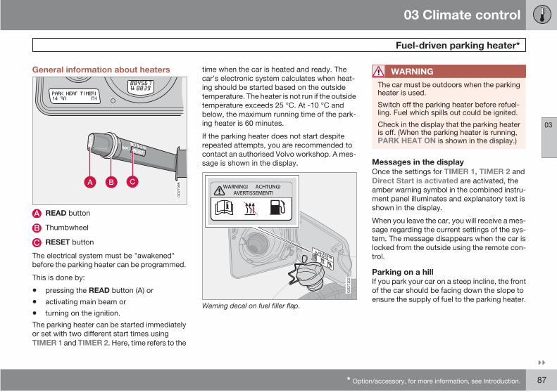
03 Climate control
Fuel-driven parking heater*
03
* Option/accessory, for more information, see Introduction. 87
General information about heaters
G02
7095
READ button
Thumbwheel
RESET button
The electrical system must be "awakened"
before the parking heater can be programmed.
This is done by:
• pressing the READ button (A) or
• activating main beam or
• turning on the ignition.
The parking heater can be started immediately
or set with two different start times using
TIMER 1 and TIMER 2. Here, time refers to the
time when the car is heated and ready. The
car's electronic system calculates when heat-
ing should be started based on the outside
temperature. The heater is not run if the outside
temperature exceeds 25 °C. At -10 °C and
below, the maximum running time of the park-
ing heater is 60 minutes.
If the parking heater does not start despite
repeated attempts, you are recommended to
contact an authorised Volvo workshop. A mes-
sage is shown in the display.
WARNING! ACHTUNG!AVERTISSEMENT!
G02
7102
Warning decal on fuel filler flap.
WARNING
The car must be outdoors when the parkingheater is used.
Switch off the parking heater before refuel-ling. Fuel which spills out could be ignited.
Check in the display that the parking heateris off. (When the parking heater is running,PARK HEAT ON is shown in the display.)
Messages in the displayOnce the settings for TIMER 1, TIMER 2 and
Direct Start is activated are activated, the
amber warning symbol in the combined instru-
ment panel illuminates and explanatory text is
shown in the display.
When you leave the car, you will receive a mes-
sage regarding the current settings of the sys-
tem. The message disappears when the car is
locked from the outside using the remote con-
trol.
Parking on a hillIf you park your car on a steep incline, the front
of the car should be facing down the slope to
ensure the supply of fuel to the parking heater.

03 Climate control
Fuel-driven parking heater*
03
88 * Option/accessory, for more information, see Introduction.
Clock/timer
If the car clock is reset after the heater timers
are programmed, the selected times will be
cancelled.
Setting the TIMER
For safety reasons, you can only programme
times for the following 24 hours, not several
days in advance.
1. Scroll using the thumbwheel until TIMERis shown in the display.
2. Briefly press RESET so that the hours set-
ting starts to flash.
3. Scroll with the thumbwheel to the desired
hour.
4. Briefly press RESET to move to the flash-
ing minutes setting.
5. Scroll with the thumbwheel to the desired
minute.
6. Briefly press RESET to confirm the setting.
7. Press RESET to activate the timer.
Deactivating timer-started parking
heaterProceed as follows to manually switch off the
parking heater before the set time has elapsed:
1. Press READ.
2. Use the thumbwheel to scroll to the text
PARK HEAT TIMER 1 or 2. The text ONflashes on the display.
3. Press RESET. The text OFF is shown with
a constant glow and the parking heater is
switched OFF.
Direct start
1. Scroll with the thumbwheel until DIRECT
START is shown in the display.
2. Press RESET to access the options ON or
OFF.
3. Select ON.
The heater will now run for 60 minutes. Heating
of the passenger compartment will begin as
soon as the engine coolant has reached a tem-
perature of 30 °C.
Immediate stop of heater
1. Scroll with the thumbwheel until DIRECT
START is shown in the display.
2. Press RESET to access options ON or
OFF.
3. Select OFF.
NOTE
The car can be started and driven while theparking heater is still running.
Battery and fuel
If the battery has insufficient charge or the fuel
level is too low, the parking heater will be
switched off automatically. A message is
shown in the display. Acknowledge the mes-
sage by pressing READ once.
IMPORTANT
Repeated use of the parking heater com-bined with short journeys may discharge thebattery and impair starting. If the heater isused regularly, the car must be driven for thesame time as the heater is used in order toensure that the alternator has time to chargethe battery.
Additional heater (diesel)*
Extra heat from the additional heater may be
required in cold weather to reach the correct
temperature in the passenger compartment.
The additional heater starts automatically
when extra heat is required if the engine is run-
ning. It is switched off automatically when the
correct temperature is reached or when the
engine is switched off.
03 Climate control
03
89
G02
0908
90
Front seats.............................................................................................. 92
Front seats - Executive .......................................................................... 94
Interior lighting........................................................................................ 95
Storage spaces in the passenger compartment..................................... 97
Storage spaces in the passenger compartment - Executive ............... 102
Rear seat............................................................................................... 103
Cargo area............................................................................................ 105
04INTERIOR
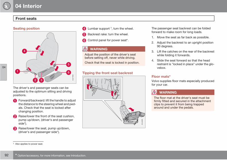
04 Interior
Front seats
04
92 * Option/accessory, for more information, see Introduction.
Seating position
G02
7960
The driver's and passenger seats can be
adjusted to the optimum sitting and driving
Forward/backward: lift the handle to adjust
the distance to the steering wheel and ped-
als. Check that the seat is locked after
changing position.
Raise/lower the front of the seat cushion,
pump up/down, (driver's and passenger
side*).
Raise/lower the seat, pump up/down,
(driver's and passenger side*).
Lumbar support 1, turn the wheel.
Backrest rake: turn the wheel.
Control panel for power seat*.
WARNING
Adjust the position of the driver's seatbefore setting off, never while driving.
Check that the seat is locked in position.
Tipping the front seat backrest
G01
4805
The passenger seat backrest can be folded
forward to make room for long loads.
1. Move the seat as far back as possible.
2. Adjust the backrest to an upright position
90 degrees.
3. Lift the catches on the rear of the backrest
while folding it forwards.
4. Slide the seat forward so that the head
restraint is "locked in place" under the glo-
vebox.
Floor mats*
Volvo supplies floor mats especially produced
for your car.
WARNING
The floor mat at the driver's seat must befirmly fitted and secured in the attachmentclips to prevent it from being trappedaround and under the pedals.
1 Also applies to power seat.
positions.

04 Interior
Front seats
04
* Option/accessory, for more information, see Introduction. 93
Power seat*
G02
7036
The seats can be adjusted for a certain time
after unlocking the door with the remote con-
trol without the key being inserted into the igni-
tion switch. The seat can always be adjusted in
ignition position I or II.
Front edge of seat cushion up/down
Seat forward/rearward
Seat up/down
Backrest rake
An overload protection is deployed if one of the
seats is blocked. If this happens, turn off the
ignition and wait a short time before adjusting
the seat again. Only one of the seat's settings
can be adjusted at a time.
Memory function*
G02
7037
Buttons for memory function.
Store setting1. Adjust seat.
2. Press and hold button MEM while pressing
button 1, 2 or 3 simultaneously.
Using a stored settingPress one of the memory buttons 1–3 until the
seat stops. If you release the button then the
movement of the seat will stop.
Key memory in remote control keyThe driver's seat positions are stored in the key
memory when the car has been locked with the
remote control key. When the car is unlocked
with the same remote control key the driver's
seat and rearview mirrors adopt the stored
positions when the driver's door is opened.
NOTE
The key memory is independent of the seatmemory.
Emergency stopIf the seat accidentally begins to move, press
any of the buttons to stop the function.
WARNING
Risk of crushing. Make sure that children donot play with the controls.
Check that there are no objects in front of,behind or under the seat during adjustment.
Ensure that none of the backseat passen-gers will be trapped.
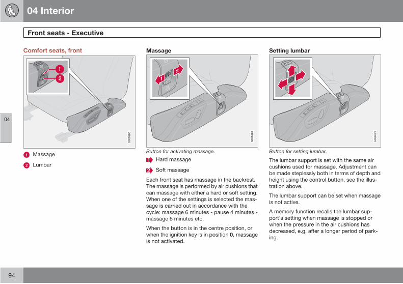
04 Interior
Front seats - Executive
04
94
Comfort seats, front
G03
0180
Massage
Lumbar
Massage
G03
0183
Button for activating massage.
Hard massage
Soft massage
Each front seat has massage in the backrest.
The massage is performed by air cushions that
can massage with either a hard or soft setting.
When one of the settings is selected the mas-
sage is carried out in accordance with the
cycle: massage 6 minutes - pause 4 minutes -
massage 6 minutes etc.
When the button is in the centre position, or
when the ignition key is in position 0, massage
is not activated.
Setting lumbar
G03
0229
Button for setting lumbar.
The lumbar support is set with the same air
cushions used for massage. Adjustment can
be made steplessly both in terms of depth and
height using the control button, see the illus-
tration above.
The lumbar support can be set when massage
is not active.
A memory function recalls the lumbar sup-
port's setting when massage is stopped or
when the pressure in the air cushions has
decreased, e.g. after a longer period of park-
ing.

04 Interior
Interior lighting
04
95
Reading lamps and interior lighting
G02
6960
Controls in roof console for front reading lampsand passenger compartment lighting.
Reading lamp left-hand front
Interior lighting
Reading lamp right-hand front
Passenger compartment lighting 1 is switched
on with a short press on button (2), at the same
time automatic lighting is activated, see
page 96. Passenger compartment lighting is
switched off with a short press on button (2).
All lighting in the passenger compartment can
be switched on in ignition position I and II as
well as when the engine is running. The lighting
can also be activated within 10 minutes after:
• the engine has been switched off and theignition is in position 0
• the car has been unlocked but the enginehas not been started
Following which, it is switched off automati-
cally.
Front roof lightingThe front reading lamps are switched on or off
by pressing the relevant button in the roof con-
sole.
Rear roof lighting
G02
7153
Rear reading lamps
Reading lamp left-hand rear, On/Off
Reading lamp right-hand rear, On/Off
The lamps are switched on or off by pressing
the relevant button.
There are also reading lamps for the third row
of seats in cars that seat seven.
Courtesy lightingCourtesy lighting (and passenger compart-
ment lighting) is switched on and off respec-
tively when a side door is opened or closed.
1 Courtesy lighting follows passenger compartment lighting.
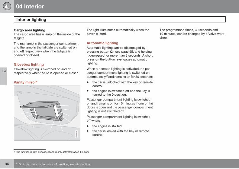
04 Interior
Interior lighting
04
96 * Option/accessory, for more information, see Introduction.
Cargo area lightingThe cargo area has a lamp on the inside of the
tailgate.
The rear lamp in the passenger compartment
and the lamp in the tailgate are switched on
and off respectively when the tailgate is
opened or closed.
Glovebox lighting
Glovebox lighting is switched on and off
respectively when the lid is opened or closed.
Vanity mirror*
G02
7045
The light illuminates automatically when the
cover is lifted.
Automatic lighting
Automatic lighting can be disengaged by
pressing button (2), see page 95, and holding
it depressed for more than 3 seconds. A short
press on the button re-engages automatic
lighting.
When automatic lighting is activated the pas-
senger compartment lighting is switched on
automatically 2 and remains on for 30 seconds:
• the car is unlocked with the key or remotecontrol
• the engine is switched off and the key isturned to the 0 position.
Passenger compartment lighting is switched
on and remains on for 10 minutes if one of the
doors is open and the passenger compartment
lighting is not switched off.
Passenger compartment lighting is switched
off when:
• the engine is started
• the car is locked with the key or remotecontrol.
The programmed times, 30 seconds and
10 minutes, can be changed by a Volvo work-
shop.
2 The function is light-dependent and is only activated when it is dark.
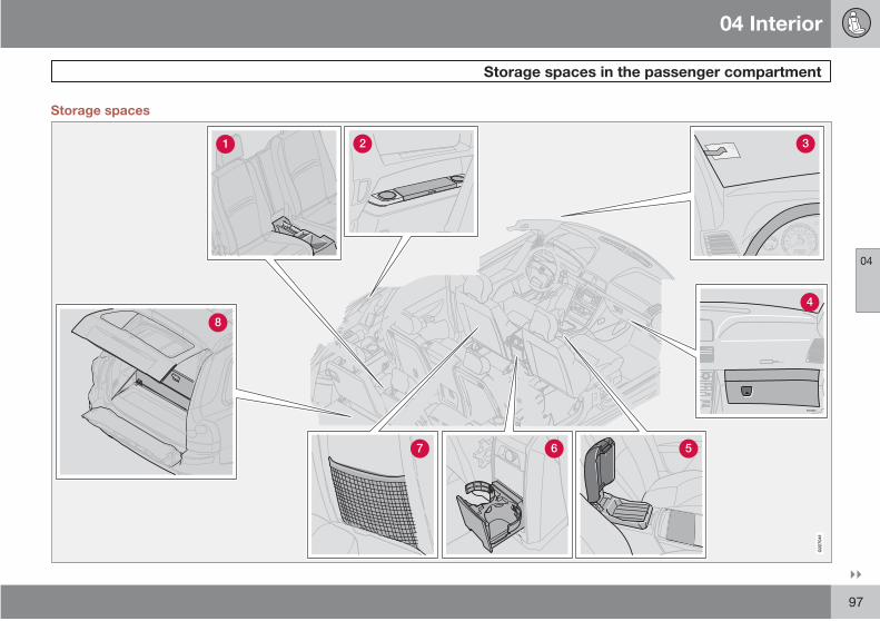
04 Interior
Storage spaces in the passenger compartment
04
97
Storage spaces
ATTENTIONPakjdskdl ioiuip kjöpp opoodidåuswi
C
SOUND
MENU
80
ENTER
LSEE
EXIT
MY KEYRTO
8504251r
AIRBAG
G02
7041

04 Interior
Storage spaces in the passenger compartment
04
98
Storage compartment in third row of seats
Storage compartment and cup holder
Ticket clip
Glovebox
Storage tray in centre console
Cup holder for rear seat passengers
Storage pocket (also on the front edge of
the front seat cushions)
Bag holder
WARNING
Ensure that no hard, sharp or heavy objectslie or protrude in such a way that they couldcause injury during heavy braking.
Always secure large and heavy objects witha seatbelt or cargo retaining straps.
Pen holder
G02
7030
The centre console contains a pen holder.
Glovebox
ATTENTIONPakjdskdl ioiuip kjöpp opoodidåuswi
C
SOUND
MENU
80
ENTER
LSE E
EXIT
MY KEYRTO
AIRBAG
G02
7025
The glovebox can be used to store things such
as the owner's manual, maps, pens and petrol
cards.
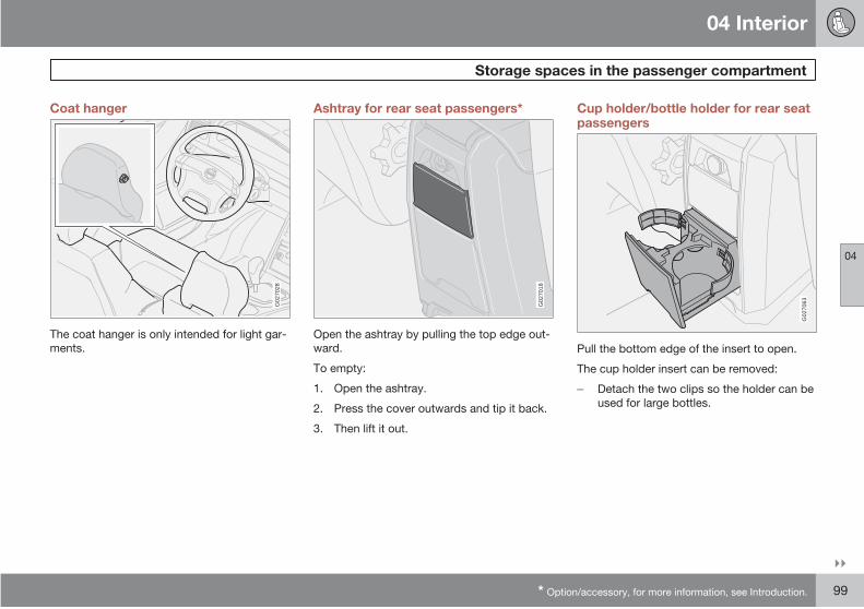
04 Interior
Storage spaces in the passenger compartment
04
* Option/accessory, for more information, see Introduction. 99
Coat hanger
G02
7028
The coat hanger is only intended for light gar-
ments.
Ashtray for rear seat passengers*
G02
7018
Open the ashtray by pulling the top edge out-
ward.
To empty:
1. Open the ashtray.
2. Press the cover outwards and tip it back.
3. Then lift it out.
Cup holder/bottle holder for rear seatpassengers
G02
7063
Pull the bottom edge of the insert to open.
The cup holder insert can be removed:
Detach the two clips so the holder can be
used for large bottles.

04 Interior
Storage spaces in the passenger compartment
04
100 * Option/accessory, for more information, see Introduction.
Storage compartment and cup holder(cars seating seven)
G02
7040
This storage compartment can be used for
CDs, books and the like.
Storage tray in centre console
G02
7019
The centre console contains a storage tray for
food and drinks, for example. The armrest can
be folded back to make a "table" for rear seat
passengers.
Under the storage tray is a storage compart-
ment, e.g. for CD discs.
Cup holder
G02
7020
Cup holder for front seat passengers.
Ashtray*Pull out the insert to empty the astray.
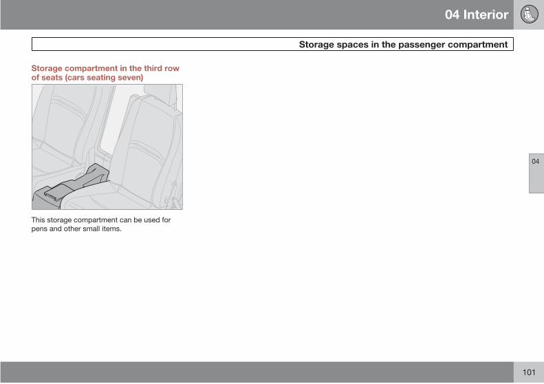
04 Interior
Storage spaces in the passenger compartment
04
101
Storage compartment in the third rowof seats (cars seating seven)
G02
7026
This storage compartment can be used for
pens and other small items.

04 Interior
Storage spaces in the passenger compartment - Executive
04
102
Refrigerator compartment
G02
7068
Under front seat's folding armrest there is a
refrigerator. It is activated in key position II. The
refrigerator holds approx. 14 litres and can cool
down to approx. 5 °C/41 °F.
WARNING
Store bottles well sealed in the refrigeratorand make sure that the refrigerator door isclosed for the journey.
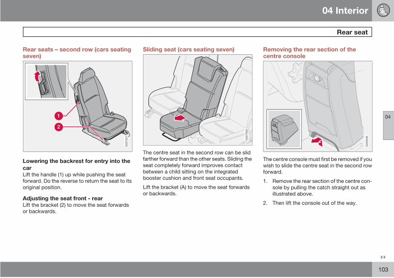
04 Interior
Rear seat
04
103
Rear seats – second row (cars seatingseven)
G02
7027
Lowering the backrest for entry into the
carLift the handle (1) up while pushing the seat
forward. Do the reverse to return the seat to its
original position.
Adjusting the seat front - rearLift the bracket (2) to move the seat forwards
or backwards.
Sliding seat (cars seating seven)
G02
7033
The centre seat in the second row can be slid
farther forward than the other seats. Sliding the
seat completely forward improves contact
between a child sitting on the integrated
booster cushion and front seat occupants.
Lift the bracket (A) to move the seat forwards
or backwards.
Removing the rear section of thecentre console
G02
8445
The centre console must first be removed if you
wish to slide the centre seat in the second row
forward.
1. Remove the rear section of the centre con-
sole by pulling the catch straight out as
illustrated above.
2. Then lift the console out of the way.
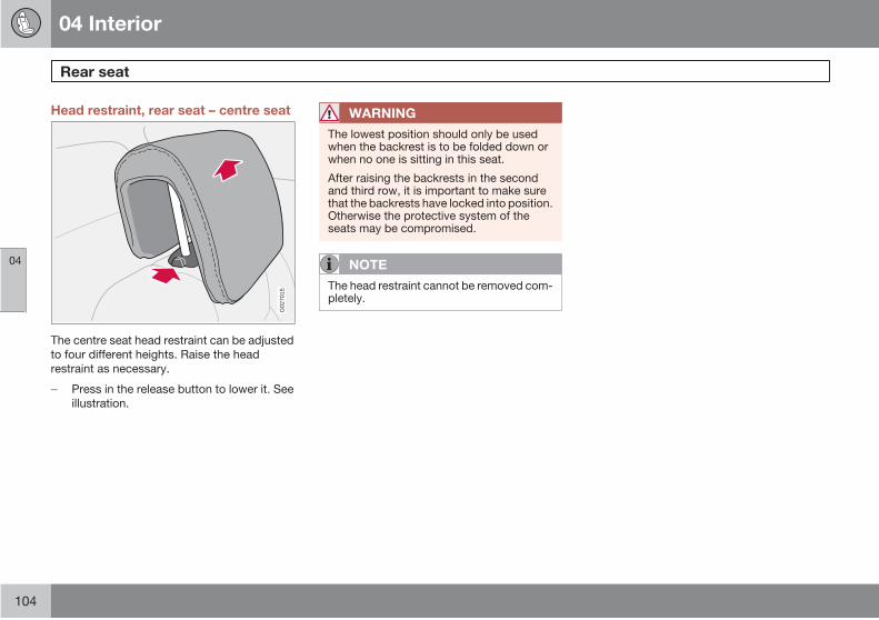
04 Interior
Rear seat
04
104
Head restraint, rear seat – centre seat
G02
7015
The centre seat head restraint can be adjusted
to four different heights. Raise the head
restraint as necessary.
Press in the release button to lower it. See
illustration.
WARNING
The lowest position should only be usedwhen the backrest is to be folded down orwhen no one is sitting in this seat.
After raising the backrests in the secondand third row, it is important to make surethat the backrests have locked into position.Otherwise the protective system of theseats may be compromised.
NOTE
The head restraint cannot be removed com-pletely.
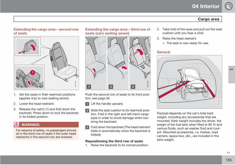
04 Interior
Cargo area
04
105
Extending the cargo area – second rowof seats
G02
7022
1. Set the seats in their rearmost positions
(applies only to cars seating seven).
2. Lower the head restraint.
3. Release the catch (1) and fold down the
backrest. Press down to lock the backrest
in its folded position.
WARNING
For reasons of safety, no passengers shouldsit in the third row of seats if the outer headrestraints in the second row are lowered.
Extending the cargo area – third row ofseats (cars seating seven)
G02
7016
Push the second row of seats to its front posi-
tion, see page 92.
Lift the handle upward.
Slide the seat cushion to its rearmost posi-
tion. Fold in the right and left-hand cargo
eyes in order to avoid damage when low-
ering the backrest.
Fold down the backrest (The head restraint
folds in automatically when the backrest is
folded).
Repositioning the third row of seats1. Raise the backrest to its normal position.
2. Take hold of the eyes and pull out the seat
cushion until you hear a click.
3. Raise the head restraint.
> The seat is now ready for use.
General
G02
7031
Payload depends on the car's total kerb
weight, including any accessories that are
mounted. Kerb weight includes the driver, the
weight of the fuel tank when filled to 90 % and
various fluids, such as washer fluid and cool-
ant. Mounted accessories, i.e. towbar, load
carriers, space box, etc., are included in the
kerb weight.
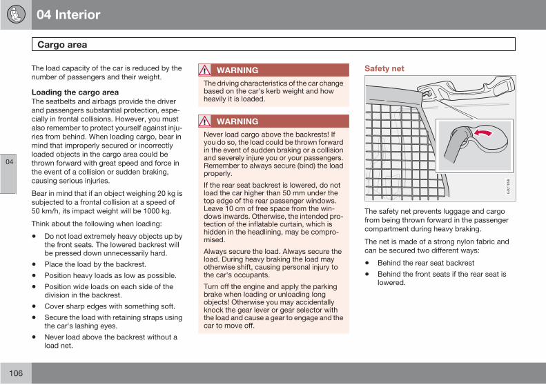
04 Interior
Cargo area
04
106
The load capacity of the car is reduced by the
number of passengers and their weight.
Loading the cargo areaThe seatbelts and airbags provide the driver
and passengers substantial protection, espe-
cially in frontal collisions. However, you must
also remember to protect yourself against inju-
ries from behind. When loading cargo, bear in
mind that improperly secured or incorrectly
loaded objects in the cargo area could be
thrown forward with great speed and force in
the event of a collision or sudden braking,
causing serious injuries.
Bear in mind that if an object weighing 20 kg is
subjected to a frontal collision at a speed of
50 km/h, its impact weight will be 1000 kg.
Think about the following when loading:
• Do not load extremely heavy objects up bythe front seats. The lowered backrest willbe pressed down unnecessarily hard.
• Place the load by the backrest.
• Position heavy loads as low as possible.
• Position wide loads on each side of thedivision in the backrest.
• Cover sharp edges with something soft.
• Secure the load with retaining straps usingthe car's lashing eyes.
• Never load above the backrest without aload net.
WARNING
The driving characteristics of the car changebased on the car's kerb weight and howheavily it is loaded.
WARNING
Never load cargo above the backrests! Ifyou do so, the load could be thrown forwardin the event of sudden braking or a collisionand severely injure you or your passengers.Remember to always secure (bind) the loadproperly.
If the rear seat backrest is lowered, do notload the car higher than 50 mm under thetop edge of the rear passenger windows.Leave 10 cm of free space from the win-dows inwards. Otherwise, the intended pro-tection of the inflatable curtain, which ishidden in the headlining, may be compro-mised.
Always secure the load. Always secure theload. During heavy braking the load mayotherwise shift, causing personal injury tothe car's occupants.
Turn off the engine and apply the parkingbrake when loading or unloading longobjects! Otherwise you may accidentallyknock the gear lever or gear selector withthe load and cause a gear to engage and thecar to move off.
Safety net
G02
7058
The safety net prevents luggage and cargo
from being thrown forward in the passenger
compartment during heavy braking.
The net is made of a strong nylon fabric and
can be secured two different ways:
• Behind the rear seat backrest
• Behind the front seats if the rear seat islowered.

04 Interior
Cargo area
04
* Option/accessory, for more information, see Introduction. 107
Fitting the safety net
G02
7059
If the car is equipped with a cargo area cover,
remove it before fitting the safety net.
1. Hook the upper rod in the front or rear roof
mounting.
2. Hook the other end of the rod in the roof
mounting on the other side.
3. Secure the safety net anchoring straps in
the eyes on the floor if the net is secured in
the rear roof mountings.
4. Use the eyes in the seat slide rail if the net
is secured in the front roof mountings.
Only applies to cars seating seven:
1. Make sure the net lies in front of the side
panel armrest when securing.
2. Tension the safety net using the anchoring
straps.
Folding up the safety net
G02
7060
The safety net can be folded up and placed in
the cargo area floor (for cars seating five).
Press the buttons (1) in the safety net
hinges to release the hinges and fold up the
net.
WARNING
Make sure that the upper mountings of thesafety net are correctly fitted and that theanchoring straps are securely fastened.
Do not use a damaged net.
Steel safety grille*
G02
7056
The protective grille in the cargo area prevents
cargo or pets from being thrown forward in the
passenger compartment in the event of heavy
braking.
For reasons of safety, the protective grille must
always be mounted and secured correctly.
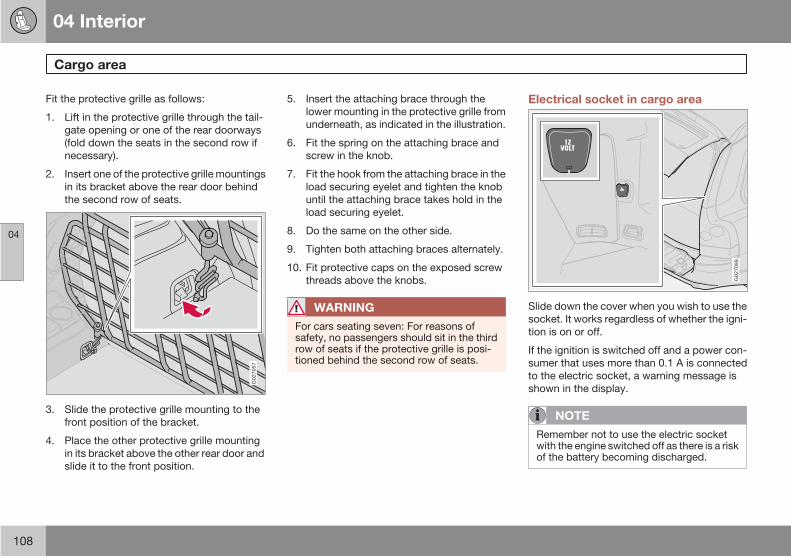
04 Interior
Cargo area
04
108
Fit the protective grille as follows:
1. Lift in the protective grille through the tail-
gate opening or one of the rear doorways
(fold down the seats in the second row if
necessary).
2. Insert one of the protective grille mountings
in its bracket above the rear door behind
the second row of seats.
G02
7057
3. Slide the protective grille mounting to the
front position of the bracket.
4. Place the other protective grille mounting
in its bracket above the other rear door and
slide it to the front position.
5. Insert the attaching brace through the
lower mounting in the protective grille from
underneath, as indicated in the illustration.
6. Fit the spring on the attaching brace and
screw in the knob.
7. Fit the hook from the attaching brace in the
load securing eyelet and tighten the knob
until the attaching brace takes hold in the
load securing eyelet.
8. Do the same on the other side.
9. Tighten both attaching braces alternately.
10. Fit protective caps on the exposed screw
threads above the knobs.
WARNING
For cars seating seven: For reasons ofsafety, no passengers should sit in the thirdrow of seats if the protective grille is posi-tioned behind the second row of seats.
Electrical socket in cargo area
G02
7099
Slide down the cover when you wish to use the
socket. It works regardless of whether the igni-
tion is on or off.
If the ignition is switched off and a power con-
sumer that uses more than 0.1 A is connected
to the electric socket, a warning message is
shown in the display.
NOTE
Remember not to use the electric socketwith the engine switched off as there is a riskof the battery becoming discharged.
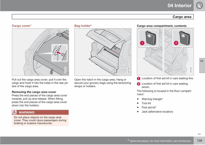
04 Interior
Cargo area
04
* Option/accessory, for more information, see Introduction. 109
Cargo cover*
G02
7055
Pull out the cargo area cover, pull it over the
cargo and hook it into the holes in the rear pil-
lars of the cargo area.
Removing the cargo area coverPress the end pieces of the cargo area cover
inwards, pull up and release. When fitting,
press the end pieces of the cargo area cover
down into the holders.
WARNING
Do not place objects on the cargo areacover. They could injure passengers duringbraking or evasive manoeuvres.
Bag holder*
G02
7066
Open the hatch in the cargo area. Hang or
secure your grocery bags using the tensioning
straps or holders.
Cargo area compartment, contents
G02
7067
Location of first aid kit in cars seating five.
Location of first aid kit in cars seating
seven.
The following is housed in the floor compart-
ment:
• Warning triangle*
• Tool kit
• First aid kit*
• Jack (alternative location)
04 Interior
Cargo area
04
110
NOTE
Some components of the first-aid kit havean expiration date and should be replacedbefore this date.
Opening the compartment in the cargo
area floor (cars seating five)Lift up the cover in the cargo area floor.
If the car is equipped with a carrier bag holder:
Lift the cover, detach the tensioning straps
to the grocery bag holder.
Opening the compartment in the cargo
area floor (cars seating seven)Lift up the cover.
If the car is equipped with a carrier bag holder:
Open the upper cover, detach the tension-
ing straps to the grocery bag holder, if
fitted, and open the lower cover.
IMPORTANT
Remember not to put anything in the areathat the cushions fold into. The cushionsand seat mechanisms could be damaged.
04 Interior
04
111

112 * Option/accessory, for more information, see Introduction.
Keys and remote controls..................................................................... 114
Locking and unlocking.......................................................................... 116
Child safety locks.................................................................................. 119
Alarm*.................................................................................................... 121

05LOCKS AND ALARM

05 Locks and alarm
Keys and remote controls
05
114
Keys – Electronic immobiliser
G03
0177
Master key This key opens all locks.
The car is supplied with two master keys. The
master keys are collapsible and equipped with
an integrated remote control.
Loss of keyIf you should lose one of your keys, bring the
remaining keys to an authorised Volvo work-
shop. The code of the missing key must be
erased from the system as a theft prevention
measure. The other keys must be re-coded in
the system at the same time.
The key blades' unique code is available at
authorised Volvo workshops, who can order
new key blades.
A maximum of six remote controls/key blades
can be programmed and used for one single
car.
ImmobiliserThe keys are fitted with coded chips. The code
must be accepted by the reader (receiver) in
the ignition switch. The car can only be started
if the correct key with the correct code is used.
NOTE
The master key blade (1) must be fullyextended (as illustrated) when starting thecar. Otherwise there is a risk that the immo-biliser function will prevent the car from star-ting.
Ignition keys and electronic immobiliserThe ignition key must not hang with other keys
or metal objects on the same key ring. The
electronic immobiliser could be activated erro-
neously and the car will not start.
Remote control functions
G02
7013
Unlocking
Press the button once to unlock all doors,
the tailgate and the fuel filler flap simulta-
neously.
Tailgate
Press the button once to unlock the tail-
gate only.
Panic alarm function
Panic function - Can be used to attract atten-
tion in an emergency. Press and hold the red
button for at least 3 seconds or press it 2 times
within the same space of time to activate the
direction indicators and the horn. The panic
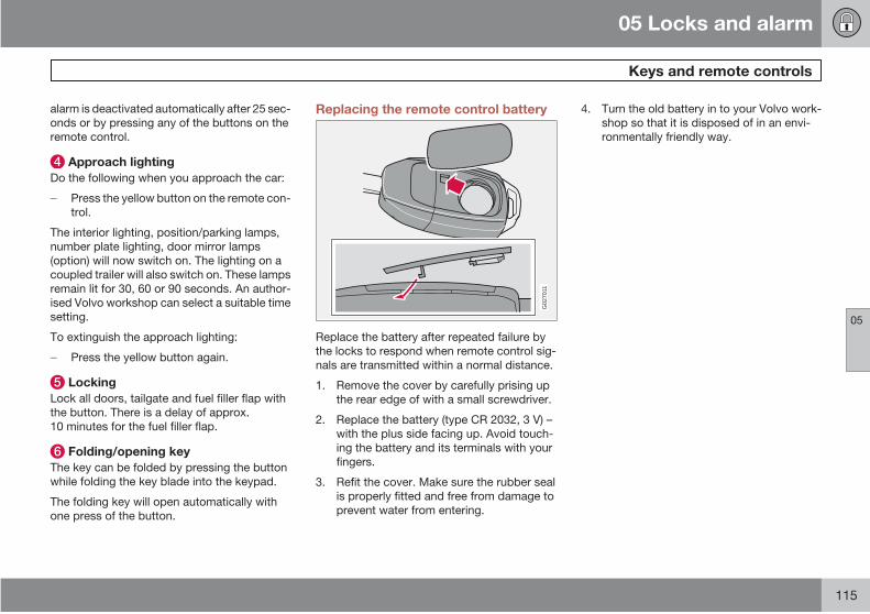
05 Locks and alarm
Keys and remote controls
05
115
alarm is deactivated automatically after 25 sec-
onds or by pressing any of the buttons on the
remote control.
Approach lighting
Do the following when you approach the car:
Press the yellow button on the remote con-
trol.
The interior lighting, position/parking lamps,
number plate lighting, door mirror lamps
(option) will now switch on. The lighting on a
coupled trailer will also switch on. These lamps
remain lit for 30, 60 or 90 seconds. An author-
ised Volvo workshop can select a suitable time
setting.
To extinguish the approach lighting:
Press the yellow button again.
Locking
Lock all doors, tailgate and fuel filler flap with
the button. There is a delay of approx.
10 minutes for the fuel filler flap.
Folding/opening key
The key can be folded by pressing the button
while folding the key blade into the keypad.
The folding key will open automatically with
one press of the button.
Replacing the remote control battery
G02
7011
Replace the battery after repeated failure by
the locks to respond when remote control sig-
nals are transmitted within a normal distance.
1. Remove the cover by carefully prising up
the rear edge of with a small screwdriver.
2. Replace the battery (type CR 2032, 3 V) –
with the plus side facing up. Avoid touch-
ing the battery and its terminals with your
fingers.
3. Refit the cover. Make sure the rubber seal
is properly fitted and free from damage to
prevent water from entering.
4. Turn the old battery in to your Volvo work-
shop so that it is disposed of in an envi-
ronmentally friendly way.
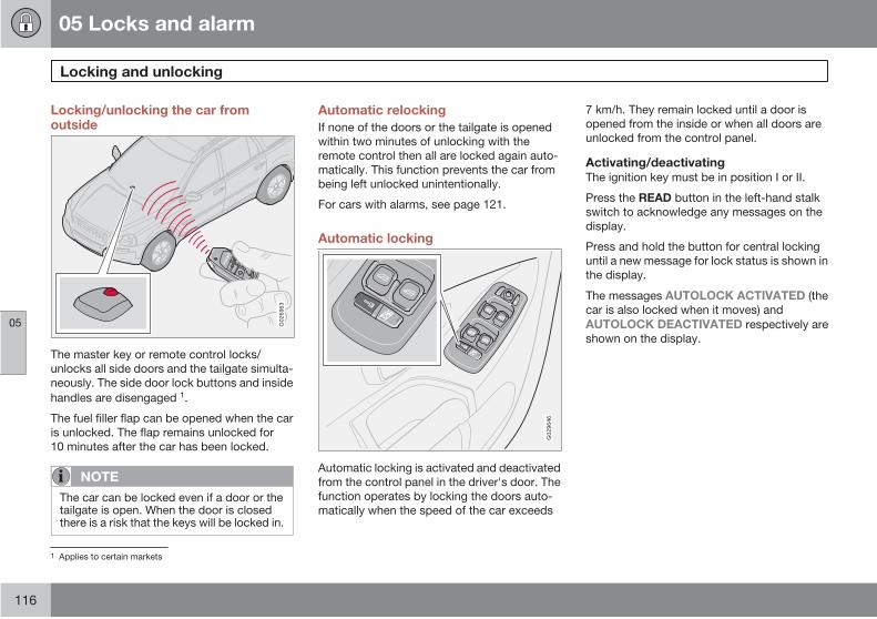
05 Locks and alarm
Locking and unlocking
05
116
Locking/unlocking the car fromoutside
G02
6963
The master key or remote control locks/
unlocks all side doors and the tailgate simulta-
neously. The side door lock buttons and inside
handles are disengaged 1.
The fuel filler flap can be opened when the car
is unlocked. The flap remains unlocked for
10 minutes after the car has been locked.
NOTE
The car can be locked even if a door or thetailgate is open. When the door is closedthere is a risk that the keys will be locked in.
Automatic relocking
If none of the doors or the tailgate is opened
within two minutes of unlocking with the
remote control then all are locked again auto-
matically. This function prevents the car from
being left unlocked unintentionally.
For cars with alarms, see page 121.
Automatic locking
G02
9646
Automatic locking is activated and deactivated
from the control panel in the driver's door. The
function operates by locking the doors auto-
matically when the speed of the car exceeds
7 km/h. They remain locked until a door is
opened from the inside or when all doors are
unlocked from the control panel.
Activating/deactivatingThe ignition key must be in position I or II.
Press the READ button in the left-hand stalk
switch to acknowledge any messages on the
display.
Press and hold the button for central locking
until a new message for lock status is shown in
the display.
The messages AUTOLOCK ACTIVATED (the
car is also locked when it moves) and
AUTOLOCK DEACTIVATED respectively are
shown on the display.
1 Applies to certain markets
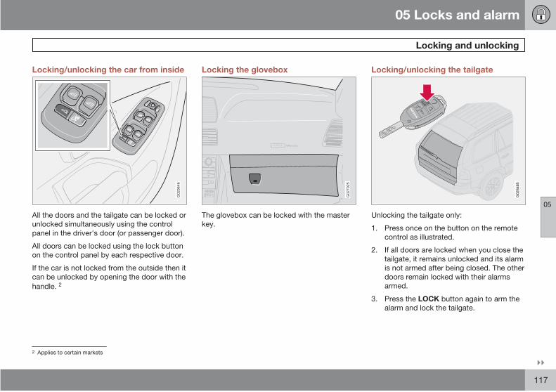
05 Locks and alarm
Locking and unlocking
05
117
Locking/unlocking the car from inside
G02
9646
All the doors and the tailgate can be locked or
unlocked simultaneously using the control
panel in the driver's door (or passenger door).
All doors can be locked using the lock button
on the control panel by each respective door.
If the car is not locked from the outside then it
can be unlocked by opening the door with the
handle. 2
Locking the glovebox
ATTENTIONPakjdskdl ioiuip kjöpp opoodidåuswi
C
SOUND
MENU
80
ENTER
LSE E
EXIT
MY KEYRTO
AIRBAG
G02
7025
The glovebox can be locked with the master
key.
Locking/unlocking the tailgate
G02
8485
Unlocking the tailgate only:
1. Press once on the button on the remote
control as illustrated.
2. If all doors are locked when you close the
tailgate, it remains unlocked and its alarm
is not armed after being closed. The other
doors remain locked with their alarms
armed.
3. Press the LOCK button again to arm the
alarm and lock the tailgate.
2 Applies to certain markets
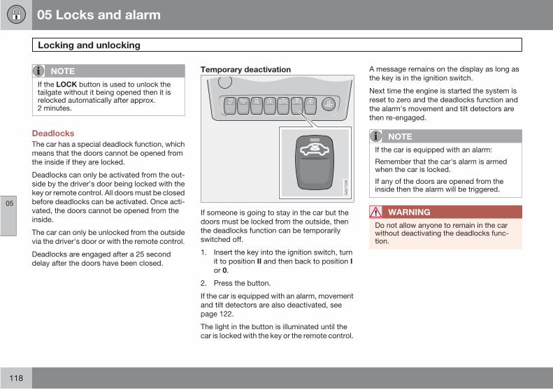
05 Locks and alarm
Locking and unlocking
05
118
NOTE
If the LOCK button is used to unlock thetailgate without it being opened then it isrelocked automatically after approx.2 minutes.
Deadlocks
The car has a special deadlock function, which
means that the doors cannot be opened from
the inside if they are locked.
Deadlocks can only be activated from the out-
side by the driver's door being locked with the
key or remote control. All doors must be closed
before deadlocks can be activated. Once acti-
vated, the doors cannot be opened from the
inside.
The car can only be unlocked from the outside
via the driver's door or with the remote control.
Deadlocks are engaged after a 25 second
delay after the doors have been closed.
Temporary deactivation
G02
7230
If someone is going to stay in the car but the
doors must be locked from the outside, then
the deadlocks function can be temporarily
switched off.
1. Insert the key into the ignition switch, turn
it to position II and then back to position I
or 0.
2. Press the button.
If the car is equipped with an alarm, movement
and tilt detectors are also deactivated, see
page 122.
The light in the button is illuminated until the
car is locked with the key or the remote control.
A message remains on the display as long as
the key is in the ignition switch.
Next time the engine is started the system is
reset to zero and the deadlocks function and
the alarm's movement and tilt detectors are
then re-engaged.
NOTE
If the car is equipped with an alarm:
Remember that the car's alarm is armedwhen the car is locked.
If any of the doors are opened from theinside then the alarm will be triggered.
WARNING
Do not allow anyone to remain in the carwithout deactivating the deadlocks func-tion.
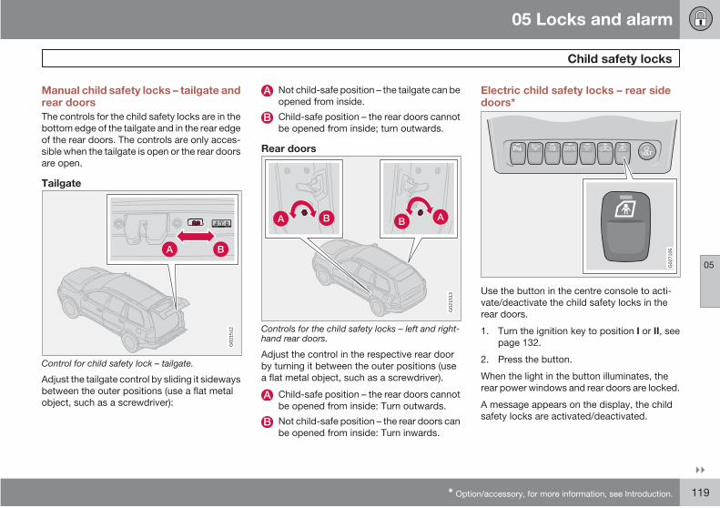
05 Locks and alarm
Child safety locks
05
* Option/accessory, for more information, see Introduction. 119
Manual child safety locks – tailgate andrear doors
The controls for the child safety locks are in the
bottom edge of the tailgate and in the rear edge
of the rear doors. The controls are only acces-
sible when the tailgate is open or the rear doors
are open.
Tailgate
G02
1512
Control for child safety lock – tailgate.
Adjust the tailgate control by sliding it sideways
between the outer positions (use a flat metal
object, such as a screwdriver):
Not child-safe position – the tailgate can be
opened from inside.
Child-safe position – the rear doors cannot
be opened from inside; turn outwards.
Rear doors
G02
1513
Controls for the child safety locks – left and right-hand rear doors.
Adjust the control in the respective rear door
by turning it between the outer positions (use
a flat metal object, such as a screwdriver).
Child-safe position – the rear doors cannot
be opened from inside: Turn outwards.
Not child-safe position – the rear doors can
be opened from inside: Turn inwards.
Electric child safety locks – rear sidedoors*
REARAC
G02
7105
Use the button in the centre console to acti-
vate/deactivate the child safety locks in the
rear doors.
1. Turn the ignition key to position I or II, see
page 132.
2. Press the button.
When the light in the button illuminates, the
rear power windows and rear doors are locked.
A message appears on the display, the child
safety locks are activated/deactivated.

05 Locks and alarm
Child safety locks
05
120
NOTE
As long as the child safety lock is activatedthe rear doors cannot be opened from theinside.

05 Locks and alarm
Alarm*
05
* Option/accessory, for more information, see Introduction. 121
Alarm system
When the alarm is armed, it continually moni-
tors all alarm inputs.
The alarm is triggered if:
• a door, the bonnet or tailgate opens
• a non-approved key is used in the ignitionor if an attempt is made to force the lock.
• a movement is detected in the passengercompartment (if fitted with a movementdetector)
• the car is raised or towed away (if fittedwith a tilt detector).
• a battery cable is disconnected.
• anyone tries to disconnect the siren.
Alarm indicator
G02
6963
A red LED on the instrument panel indicates
the alarm system's status:
• LED not lit – the alarm is not armed.
• The LED flashes once every other second– Alarm is armed.
• The LED flashes rapidly after disarming thealarm and until the ignition is switched on– the alarm has been triggered.
If there is a fault in the alarm system, a message
appears on the display. Contact an authorised
Volvo workshop.
NOTE
Do not attempt to repair or modify alarmsystem components. All such attemptscould affect the terms of insurance.
Arming the alarm
Press the LOCK button. A long flash from
the car's direction indicators confirms that
the alarm is armed and that all the doors
are locked.
IMPORTANT
The alarm is fully armed when the car'sdirection indicators have made one longflash and the LED on the instrument panelflashes once every other second.
Disarming the alarm
Press the remote control's UNLOCK but-
ton. Two short flashes from the car's direc-
tion indicators confirm that the alarm has
been deactivated.
If the remote control batteries are discharged
then the alarm can be disarmed by turning the
ignition key to position II.
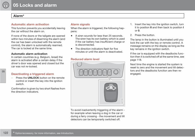
05 Locks and alarm
Alarm*
05
122 * Option/accessory, for more information, see Introduction.
Automatic alarm activation
This function prevents you accidentally leaving
the car without the alarm on.
If none of the doors or the tailgate are opened
within two minutes of disarming the alarm (and
the car has been unlocked with the remote
control), the alarm is automatically rearmed.
The car is locked at the same time.
Automatic alarm activationIn certain countries (e.g. Belgium, Israel) the
alarm is activated after a certain delay if the
driver's door was opened and closed but the
car was not re-locked.
Deactivating a triggered alarm
Press the UNLOCK button on the remote
control or insert the key into the ignition
switch.
Confirmation is given by two short flashes from
the direction indicators.
Alarm signals
When the alarm is triggered, the following hap-
pens:
• A siren sounds for less than 25 seconds.The siren has its own battery which is usedif the car battery has insufficient charge oris disconnected.
• The direction indicators flash for fiveminutes or until the alarm is deactivated.
Reduced alarm level
G02
7230
To avoid inadvertently triggering of the alarm -
for example when leaving a dog in the car or
during a ferry crossing - the movement and tilt
detectors can be temporarily switched off.
1. Insert the key into the ignition switch, turn
it to position II and then back to position I
or 0.
2. Press the button.
The lamp in the button is illuminated until you
lock the car with the key or remote control. A
message remains on the display as long as the
key remains in the ignition switch.
If the car is equipped with the deadlocks func-
tion then it is switched off at the same time, see
page 118.
Next time the engine is started the system is
reset to zero and the movement and tilt detec-
tors and the deadlocks function are then re-
engaged.
05 Locks and alarm
05
123

G02
0912
124 * Option/accessory, for more information, see Introduction.
General.................................................................................................. 126
Refuelling.............................................................................................. 128
Starting the engine................................................................................ 132
Manual gearbox.................................................................................... 134
Automatic gearbox................................................................................ 135
All-wheel drive*..................................................................................... 138
Brake system........................................................................................ 139
Stability and traction control system*................................................... 141
Parking assistance*............................................................................... 143
Blind Spot Information System - BLIS*................................................. 145
Towing and recovery............................................................................. 149
Start assistance.................................................................................... 151
Driving with a trailer.............................................................................. 152
Towing equipment*............................................................................... 154
Detachable towbar*............................................................................... 156
Loading................................................................................................. 160
Adjusting headlamp pattern.................................................................. 161
06STARTING AND DRIVING
06 Starting and driving
General
06
126
Economical driving
Driving economically means driving smoothly
while thinking ahead and adjusting your driving
style and speed to the prevailing conditions.
For more advice on reducing environmental
impact. see page 12.
• Get the engine warmed up as soon as pos-sible.
• Do not let the engine idle, but drive at lightloads as soon as it is possible. A coldengine consumes more fuel than a warmone.
• Avoid sudden unnecessary accelerationand heavy braking.
• Do not drive with unnecessary loads in thecar.
• Do not use winter tyres when the roads aredry.
• Remove the load carrier when it is not inuse.
• Avoid driving with open windows.
Slippery driving conditions
Practise driving on slippery surfaces under
controlled conditions to learn how the car
reacts.
Engine and cooling system
Under special conditions, for example when
driving in hilly terrain, extreme heat or with
heavy loads, there is a risk that the engine and
cooling system will overheat.
Avoid overheating the cooling system
• Maintain a low speed when driving with atrailer up long, steep ascents.
• Do not turn the engine off immediately youstop after a hard drive.
• Remove any auxiliary lamps from in frontof the grille if driving in extreme high tem-peratures.
Avoid overheating the engineDo not exceed engine speeds of 4500 rpm
(diesel engines: 3500 rpm) if driving with a
trailer or caravan in hilly terrain. The oil tem-
perature could then become too high.
Open tailgate
Avoid driving with the tailgate open. If it is nec-
essary to drive with the tailgate open for a short
distance:
1. Close all windows.
2. Set the air distribution to the windscreen
and floor and run the fan at high speed.
WARNING
Do not drive with the tailgate open. Toxicexhaust fumes can be drawn into the carthrough the cargo area.
Driving on rough roads
The Volvo XC90 is primarily designed for driv-
ing on main roads, but also has good handling
properties on uneven or rough roads. Keep the
following in mind in order to preserve the serv-
ice life of your car:
• Drive slowly on rough roads so you do notdamage the car's underbody.
• If the ground is loose or is made up of drysand or snow, it is always best to keep thecar moving at all times and avoid shifting.Do not stop the car.
• If the road is extremely steep and there isa risk of overturning, never try to turn thecar around. Reverse back down. Do not
06 Starting and driving
General
06
127
drive diagonally across an incline. Drive inthe direction of the incline.
NOTE
Avoid driving on steep slopes if the fuel levelis low. The catalytic converter could bedamaged if the engine does not receiveenough fuel. When driving on extremelysteep slopes, make sure the tank is morethan half full to avoid the risk of breakdown.
Driving in water
The car can be driven through water at a maxi-
mum depth of 40 cm at a maximum speed of
10 km/h. Extra caution should be exercised
when passing through flowing water.
IMPORTANT
Engine damage can occur if water entersthe air filter.
In greater depths, water can enter the trans-mission. This reduces the lubricating abilityof the oils and shortens the service life of thesystems.
During driving in water, maintain a low speed
and do not stop the car. When the water has
been passed, depress the brake pedal lightly
and check that full brake function is achieved.
Water and mud for example can make the
brake linings wet resulting in delayed brake
function.
NOTE
Clean the electric contacts of the electricengine block heater and trailer couplingafter driving in water and mud.
IMPORTANT
Do not let the car stand with water over thesills for any long period of time. This couldcause electrical malfunctions.
In the event of engine stop in water do nottry restart. Tow the car from the water.
Do not overload the battery
The electrical functions in the car load the bat-
tery to varying degrees. Avoid having the igni-
tion key in position II when the engine is turned
off. Use position I instead, as less power is
used. The 12 volt outlet in the cargo area sup-
plies power even when the ignition key is
removed.
Examples of functions that use a lot of power:
• ventilation fan
• windscreen wipers
• audio equipment (high volume)
• parking lights
Also, be aware of different accessories that
load the electrical system. Do not use functions
which use a lot of power when the engine is
switched off.
If the battery voltage is low, a message appears
on the display. The energy-saving function
shuts down certain functions or reduces the
load on the battery by, for example, slowing the
ventilation fan and switching off the audio sys-
tem. Charge the battery by starting the engine.
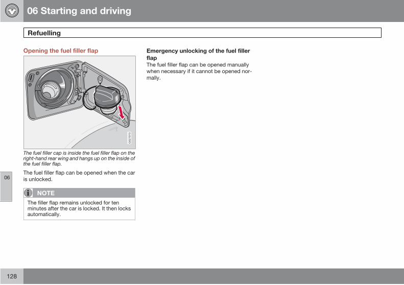
06 Starting and driving
Refuelling
06
128
Opening the fuel filler flap
G02
7073
The fuel filler cap is inside the fuel filler flap on theright-hand rear wing and hangs up on the inside ofthe fuel filler flap.
The fuel filler flap can be opened when the car
is unlocked.
NOTE
The filler flap remains unlocked for tenminutes after the car is locked. It then locksautomatically.
Emergency unlocking of the fuel filler
flapThe fuel filler flap can be opened manually
when necessary if it cannot be opened nor-
mally.
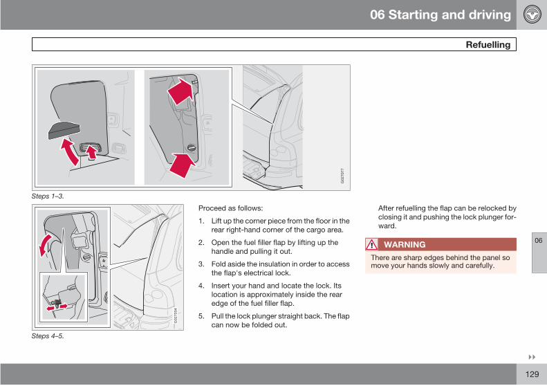
06 Starting and driving
Refuelling
06
129
G02
7077
Steps 1–3.
G02
7034
Steps 4–5.
Proceed as follows:
1. Lift up the corner piece from the floor in the
rear right-hand corner of the cargo area.
2. Open the fuel filler flap by lifting up the
handle and pulling it out.
3. Fold aside the insulation in order to access
the flap's electrical lock.
4. Insert your hand and locate the lock. Its
location is approximately inside the rear
edge of the fuel filler flap.
5. Pull the lock plunger straight back. The flap
can now be folded out.
After refuelling the flap can be relocked by
closing it and pushing the lock plunger for-
ward.
WARNING
There are sharp edges behind the panel somove your hands slowly and carefully.

06 Starting and driving
Refuelling
06
130 * Option/accessory, for more information, see Introduction.
Fuel cap
A certain overpressure may arise in the tank in
the event of high outside temperatures. Open
NOTE
Put the petrol cap back on after refuelling.Turn until one or more clear clicks are heard.
Filling up with fuel
Do not overfill the tank but fill until the pump
nozzle cuts out.
NOTE
Excess fuel in the tank can overflow in hotweather.
Fuel of a lower quality than that specified
should not be used as engine power and fuel
consumption can be negatively affected, see
page 273.
WARNING
Fuel which spills onto the ground can beignited by the exhaust fumes.
Switch off the fuel-driven heater before star-ting to refuel.
Never carry an activated mobile phonewhen refuelling. The ring signal could causespark build-up and ignite petrol fumes,leading to fire and injury.
Petrol
IMPORTANT
Do not add cleaning additives to the petrol,unless recommended by Volvo.
DieselAt low temperatures (–5 °C to –40 °C), a paraffin
precipitate may form in the diesel fuel, which
can lead to ignition problems.
IMPORTANT
Use special winter grade fuel during coldmonths.
Diesel particle filter (DPF)*
Diesel cars may be equipped with a particle fil-
ter, which results in more efficient emission
control. The particles in the exhaust gases are
collected in the filter during normal driving. So-
called "regeneration" is started in order to burn
away the particles and empty the filter. This
requires the engine to have reached normal
operating temperature.
Regeneration of the filter takes place automat-
ically at an interval of approximately
300 – 900 km depending on driving conditions.
Regeneration normally takes 10-20 minutes. It
may take a little longer at a low average speed.
Fuel consumption may increase slightly during
regeneration.
The rear window heating may be activated
automatically to increase the load on the
engine during regeneration without warning.
Regeneration in cold weatherIf the car is frequently driven short distances in
cold weather then the engine does not reach
normal operating temperature. This means that
regeneration of the diesel particle filter does
not take place and the filter is not emptied.
When the filter has become approximately
80% full of particles, the yellow information
symbol on the instrument panel illuminates,
and the message SOOT FILTER FULL SEE
the cap slowly.
06 Starting and driving
Refuelling
06
131
MANUAL is shown on the instrument panel
display. Start regeneration of the filter by driv-
ing the car until the engine reaches normal
operating temperature, preferably on a main
road or motorway. The car should then be
driven for approximately 20 minutes more.
When regeneration is complete the message is
cleared automatically.
IMPORTANT
If the filter fills up it may be incapable offunctioning. Then it can be difficult to startthe engine and there is a risk that the filterwill have to be replaced.
Use the parking heater* in cold weather so that
the engine reaches normal operating tempera-
ture more quickly.
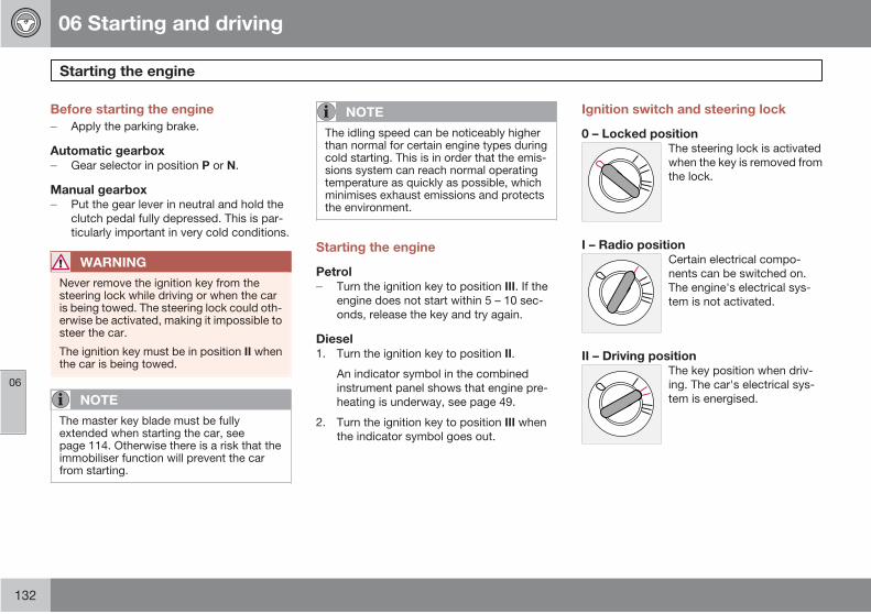
06 Starting and driving
Starting the engine
06
132
Before starting the engine
Apply the parking brake.
Automatic gearboxGear selector in position P or N.
Manual gearboxPut the gear lever in neutral and hold the
clutch pedal fully depressed. This is par-
ticularly important in very cold conditions.
WARNING
Never remove the ignition key from thesteering lock while driving or when the caris being towed. The steering lock could oth-erwise be activated, making it impossible tosteer the car.
The ignition key must be in position II whenthe car is being towed.
NOTE
The master key blade must be fullyextended when starting the car, seepage 114. Otherwise there is a risk that theimmobiliser function will prevent the carfrom starting.
NOTE
The idling speed can be noticeably higherthan normal for certain engine types duringcold starting. This is in order that the emis-sions system can reach normal operatingtemperature as quickly as possible, whichminimises exhaust emissions and protectsthe environment.
Starting the engine
PetrolTurn the ignition key to position III. If the
engine does not start within 5 – 10 sec-
onds, release the key and try again.
Diesel1. Turn the ignition key to position II.
An indicator symbol in the combined
instrument panel shows that engine pre-
heating is underway, see page 49.
2. Turn the ignition key to position III when
the indicator symbol goes out.
Ignition switch and steering lock
0 – Locked positionThe steering lock is activated
when the key is removed from
the lock.
I – Radio positionCertain electrical compo-
nents can be switched on.
The engine's electrical sys-
tem is not activated.
II – Driving positionThe key position when driv-
ing. The car's electrical sys-
tem is energised.

06 Starting and driving
Starting the engine
06
133
III – Start positionThe starter motor is engaged.
When the key is released it
springs back automatically to
the driving position, once the
engine has started.
If the key is hard to turn, the
front wheels may be turned in such a way that
there is tension in the steering wheel lock. In
which case, turn the wheel back and forth to
make it easier to turn the key.
Autostart (3.2 and V8)Using the autostart function, the ignition key
does not need to be kept in the start position
(position III) until the engine has started. Turn
the ignition key to the start position and then
release. The starter motor then operates auto-
matically (up to ten seconds) until the engine
has started.
NOTE
Make sure the steering wheel locks whenyou leave the car. This reduces the risk oftheft.
Ignition keys and electronicimmobiliser
The ignition key must not hang with other keys
or metal objects on the same key ring. The
electronic immobiliser could be activated acci-
dentally.
Never rev the engine hard straight after a cold
start! If the engine does not start or misfires,
contact a Volvo workshop.
WARNING
Never switch off the ignition (position 0 or1) or remove the ignition key while the car ismoving. The steering lock could otherwisebe activated, making it impossible to steerthe car.
Always remove the ignition key from thesteering lock when leaving the car – espe-cially if children are left alone in the car.
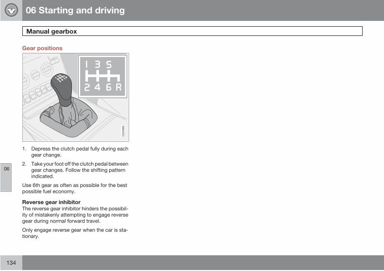
06 Starting and driving
Manual gearbox
06
134
Gear positions
G02
6988
1. Depress the clutch pedal fully during each
gear change.
2. Take your foot off the clutch pedal between
gear changes. Follow the shifting pattern
indicated.
Use 6th gear as often as possible for the best
possible fuel economy.
Reverse gear inhibitorThe reverse gear inhibitor hinders the possibil-
ity of mistakenly attempting to engage reverse
gear during normal forward travel.
Only engage reverse gear when the car is sta-
tionary.
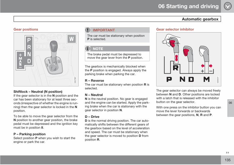
06 Starting and driving
Automatic gearbox
06
135
Gear positions
G02
7997
Shiftlock – Neutral (N position)If the gear selector is in the N position and the
car has been stationary for at least three sec-
onds (irrespective of whether the engine is run-
ning) then the gear selector is locked in the N
position.
To be able to move the gear selector from the
N position to another gear position, the brake
pedal must be depressed and the ignition key
must be in position II.
P – Parking positionSelect position P when you wish to start the
engine or park the car.
IMPORTANT
The car must be stationary when positionP is selected.
NOTE
The brake pedal must be depressed tomove the gear lever from the P position.
The gearbox is mechanically blocked when
the P position is engaged. Always apply the
parking brake when parking the car.
R – ReverseThe car must be stationary when position R is
selected.
N – NeutralN is the neutral position. No gear is engaged
and the engine can be started. Apply the park-
ing brake when the car is stationary with the
gear selector in position N.
D – DriveD is the normal driving position. The car auto-
matically shifts between the different gears of
the gearbox based on the level of acceleration
and speed. The car must be stationary when
the gear selector is moved to position D from
position R.
Gear selector inhibitor
G02
0237
The gear selector can always be moved freely
between N and D. Other positions are locked
with a latch that is released with the inhibitor
button on the gear selector.
With one press on the inhibitor button you can
move the lever forwards or backwards
between the gear positions, N, R and P.
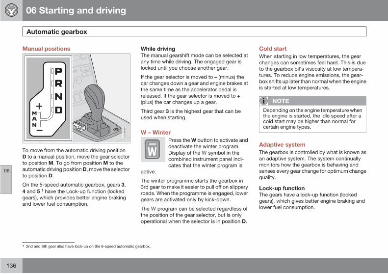
06 Starting and driving
Automatic gearbox
06
136
Manual positions
G02
6990
To move from the automatic driving position
D to a manual position, move the gear selector
to position M. To go from position M to the
automatic driving position D, move the selector
to position D.
On the 5-speed automatic gearbox, gears 3,
4 and 5 1 have the Lock-up function (locked
gears), which provides better engine braking
and lower fuel consumption.
While drivingThe manual gearshift mode can be selected at
any time while driving. The engaged gear is
locked until you choose another gear.
If the gear selector is moved to – (minus) the
car changes down a gear and engine brakes at
the same time as the accelerator pedal is
released. If the gear selector is moved to +
(plus) the car changes up a gear.
Third gear 3 is the highest gear that can be
used when starting.
W – Winter
Press the W button to activate and
deactivate the winter program.
Display of the W symbol in the
combined instrument panel indi-
cates that the winter program is
active.
The winter programme starts the gearbox in
3rd gear to make it easier to pull off on slippery
roads. When the programme is engaged, lower
gears are activated only by kick-down.
The W program can be selected regardless of
the position of the gear selector, but is only
operational when the selector is in position D.
Cold start
When starting in low temperatures, the gear
changes can sometimes feel hard. This is due
to the gearbox oil's viscosity at low tempera-
tures. To reduce engine emissions, the gear-
box shifts up later than normal when the engine
is started at low temperatures.
NOTE
Depending on the engine temperature whenthe engine is started, the idle speed after acold start may be higher than normal forcertain engine types.
Adaptive system
The gearbox is controlled by what is known as
an adaptive system. The system continually
monitors how the gearbox is behaving and
senses every gear change for optimum change
quality.
Lock-up functionThe gears have a lock-up function (locked
gears), which gives better engine braking and
lower fuel consumption.
1 2nd and 6th gear also have lock-up on the 6-speed automatic gearbox.

06 Starting and driving
Automatic gearbox
06
137
Kick-down
When the accelerator pedal is pressed all the
way to the floor, beyond the position normally
regarded as full acceleration, a lower gear is
immediately engaged. This is known as kick-
down.
If the accelerator is released from the kick-
down position, the gearbox automatically
changes up.
Kick-down is used when maximum accelera-
tion is needed, such as for overtaking.
To prevent overrevving, the gearbox control
program has a protective downshift inhibitor
which prevents the kick-down function.
The kick-down function cannot be used in
manual gear position.
Safety systems
Cars with an automatic gearbox have special
safety systems:
KeylockTo remove the ignition key, the gear selector
must be in the P position. The key is locked in
all other positions.
Parking position (P)Stationary car with engine running:
Keep your foot on the brake pedal when
moving the gear selector to another posi-
tion.
Electric gear inhibitor – Shiftlock Parking
position (P position)To be able to move the gear selector from the
P position to other gear positions, the ignition
key must be in position I or II and the brake
pedal must be depressed.
06 Starting and driving
All-wheel drive*
06
138 * Option/accessory, for more information, see Introduction.
All-wheel drive – AWD
All-wheel drive is always engaged.
All-wheel drive means that all four road wheels
are driven at the same time. The power is auto-
matically distributed between the front and rear
wheels. An electronically controlled clutch sys-
tem distributes the power to the pair of wheels
that grips best. This provides the best traction
and prevents wheel spin.
Under normal driving conditions, the majority
of power is transmitted to the front wheels.
All-wheel drive improves driving safety in rain,
snow and icy conditions.

06 Starting and driving
Brake system
06
139
Brake servo
If the car is rolling or is being towed with the
engine turned off, the brake pedal must be
pressed about five times harder than when the
engine is running. If the brake pedal is
depressed when the engine is started, you will
feel the pedal drop. This is normal and due to
the brake servo becoming active. This may be
more noticeable if the car has Emergency
Brake Assistance (EBA).
WARNING
The brake servo only works when the engineis running.
NOTE
If braking with the engine switched off,press the brake pedal sharply once, notrepeatedly.
Brake circuits
This symbol illuminates if a brake
circuit is not working.
If a fault should occur in one of the
circuits, it is still possible to brake
the car. The brake pedal will travel further and
may feel softer than normal. Harder pressure
on the pedal is needed to produce the normal
braking effect.
Dampness can affect braking
characteristicsBrake components become wet when the car
is driven in heavy rain, through pools of water
or when the car is washed. This may alter brake
pad friction characteristics so that there is a
delay before braking effect is noticed.
Press the brake pedal lightly from time to time
if driving for long stretches in rain or slushy
snow, as well as after setting off in very damp
or cold weather. This warms up the brake pads
and dries off any water. This precaution is also
recommended before parking the car for a long
period in such weather conditions.
If the brakes are used heavily
When driving in the Alps or other roads with
similar characteristics, the car's brakes are
heavily loaded even if the brake pedal is not
being depressed especially hard.
Because speed is often low, the brakes are not
cooled as effectively as when driving on flat
roads at higher speed.
So as not to overload the brakes, shift down
when driving downhill instead of using the foot
brake. Use the same gear driving downhill as
you would use driving uphill. This uses engine
braking more efficiently so the foot brake is
only required for brief periods.
Bear in mind that driving with a trailer puts an
additional load on the car's brakes.
Anti-lock braking system (ABS)
The anti-lock braking system
(ABS) prevents the wheels from
locking up during braking.
This means the ability to steer is
maintained and it is easier to swerve to avoid a
hazard for example.
After the engine has been started, the ABS will
perform a brief self-test at a speed of
about 20 km/h. This can be felt and heard as
pulses in the brake pedal.
To get the most out of the ABS:
1. Depress the brake pedal with full force.
Pulses will be felt.
2. Steer the car in the direction of travel. Do
not release the pressure on the pedal.
Practice braking with the ABS system in a traf-
fic-free area and in different weather condi-
tions.
The ABS symbol illuminates for two seconds if
there was a fault in the ABS system when the
engine was last running.
06 Starting and driving
Brake system
06
140
Electronic brake force distributionsystem – EBD
The Electronic Brakeforce Distribution system
(EBD) is an integrated part of the ABS system.
The EBD system controls the brake force to the
rear wheels so that the best possible braking
force is always available. Pulses will be heard
and felt through the brake pedal when the sys-
tem regulates brake force.
WARNING
If the BRAKE and ABS warning symbols illu-minate at the same time, there may be afault in the brake system. If the level in thebrake fluid reservoir is normal at this stage,drive carefully to the nearest authorisedVolvo workshop and have the brake systemchecked.
If the brake fluid is under the MIN level in thebrake fluid reservoir, do not drive furtherbefore topping up the brake fluid.
The reason for the loss of brake fluid mustbe investigated.
Emergency Brake Assistance – EBA
(Emergency Brake Assistance) For sudden
braking, full-strength braking is provided
instantaneously. The EBA function senses
when heavy braking is underway by registering
how quickly the brake pedal is depressed.
Continue braking without easing off on the
brake pedal. The function is suspended when
the pressure on the brake pedal eases. This
function is always active. It cannot be disen-
gaged.
NOTE
When EBA is activated the brake pedal low-ers slightly more than usual, depress (hold)the brake pedal as long as necessary. If thebrake pedal is released then all brakingceases.
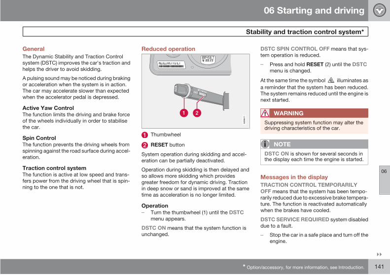
06 Starting and driving
Stability and traction control system*
06
* Option/accessory, for more information, see Introduction. 141
General
The Dynamic Stability and Traction Control
system (DSTC) improves the car's traction and
helps the driver to avoid skidding.
A pulsing sound may be noticed during braking
or acceleration when the system is in action.
The car may accelerate slower than expected
when the accelerator pedal is depressed.
Active Yaw ControlThe function limits the driving and brake force
of the wheels individually in order to stabilise
the car.
Spin ControlThe function prevents the driving wheels from
spinning against the road surface during accel-
eration.
Traction control systemThe function is active at low speed and trans-
fers power from the driving wheel that is spin-
ning to the one that is not.
Reduced operation
G02
8511
Thumbwheel
RESET button
System operation during skidding and accel-
eration can be partially deactivated.
Operation during skidding is then delayed and
so allows more skidding which provides
greater freedom for dynamic driving. Traction
in deep snow or sand is improved at the same
time as acceleration is no longer limited.
OperationTurn the thumbwheel (1) until the DSTCmenu appears.
DSTC ON means that the system function is
unchanged.
DSTC SPIN CONTROL OFF means that sys-
tem operation is reduced.
Press and hold RESET (2) until the DSTCmenu is changed.
At the same time the symbol illuminates as
a reminder that the system has been reduced.
The system remains reduced until the engine is
next started.
WARNING
Suppressing system function may alter thedriving characteristics of the car.
NOTE
DSTC ON is shown for several seconds inthe display each time the engine is started.
Messages in the display
TRACTION CONTROL TEMPORARILY
OFF means that the system has been tempo-
rarily reduced due to excessive brake tempera-
ture. The function is reactivated automatically
when the brakes have cooled.
DSTC SERVICE REQUIRED system disabled
due to a fault.
Stop the car in a safe place and turn off the
engine.
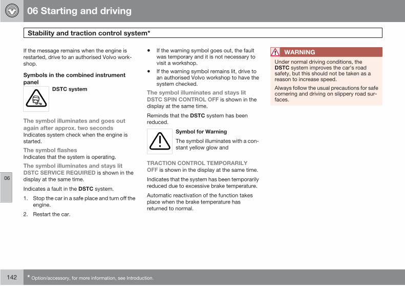
06 Starting and driving
Stability and traction control system*
06
142 * Option/accessory, for more information, see Introduction.
If the message remains when the engine is
restarted, drive to an authorised Volvo work-
shop.
Symbols in the combined instrument
panelDSTC system
The symbol illuminates and goes out
again after approx. two secondsIndicates system check when the engine is
started.
The symbol flashesIndicates that the system is operating.
The symbol illuminates and stays litDSTC SERVICE REQUIRED is shown in the
display at the same time.
Indicates a fault in the DSTC system.
1. Stop the car in a safe place and turn off the
engine.
2. Restart the car.
• If the warning symbol goes out, the faultwas temporary and it is not necessary tovisit a workshop.
• If the warning symbol remains lit, drive toan authorised Volvo workshop to have thesystem checked.
The symbol illuminates and stays litDSTC SPIN CONTROL OFF is shown in the
display at the same time.
Reminds that the DSTC system has been
reduced.
Symbol for Warning
The symbol illuminates with a con-
stant yellow glow and
TRACTION CONTROL TEMPORARILY
OFF is shown in the display at the same time.
Indicates that the system has been temporarily
reduced due to excessive brake temperature.
Automatic reactivation of the function takes
place when the brake temperature has
returned to normal.
WARNING
Under normal driving conditions, theDSTC system improves the car's roadsafety, but this should not be taken as areason to increase speed.
Always follow the usual precautions for safecornering and driving on slippery road sur-faces.
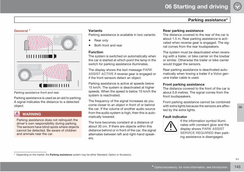
06 Starting and driving
Parking assistance*
06
* Option/accessory, for more information, see Introduction. 143
General 1
G02
0294
Parking assistance front and rear.
Parking assistance is used as an aid to parking.
A signal indicates the distance to a detected
object.
WARNING
Parking assistance does not relinquish thedriver's own responsibility during parking.The sensors have blind spots where objectscannot be detected. Be aware of childrenand animals near the car.
VariantsParking assistance is available in two variants:
• Rear only
• Both front and rear
FunctionThe system is switched on automatically when
the car is started at which point the lamp in the
switch for parking assistance illuminates.
The display shows the text message PARK
ASSIST ACTIVE if reverse gear is engaged or
if the front sensors detect an object.
Parking assistance is active at speeds below
15 km/h. The system is deactivated at higher
speeds. When the speed is below 10 km/h the
system is reactivated.
The frequency of the signal increases as you
come closer to an object in front of or behind
the car. If the volume of another audio source
from the audio system is high, then this is auto-
matically lowered.
The tone becomes constant at a distance of
about 30 cm. If there are objects within this
distance behind or in front of the car, the signal
alternates between left and right-hand speak-
ers.
Rear parking assistanceThe distance covered to the rear of the car is
about 1.5 m. Rear parking assistance is acti-
vated when reverse gear is engaged. The sig-
nal comes from the rear loudspeakers.
The system must be deactivated when revers-
ing with a trailer, or bike carrier on the towbar
or similar. Otherwise the trailer or bike carrier
would trigger the sensors.
Rear parking assistance is deactivated auto-
matically when towing a trailer if a Volvo gen-
uine trailer cable is used.
Front parking assistanceThe distance covered to the front of the car is
about 0.8 metres. The signal comes from the
front loudspeakers.
Front parking assistance cannot be combined
with extra lights because the sensors are affec-
ted by the extra lights.
Fault indicatorIf the information symbol illumi-
nates with constant glow and the
display shows PARK ASSIST
SERVICE REQUIRED then park-
ing assistance is disengaged.
1 Depending on the market, the Parking assistance system may be either Standard, Option or Accessory.
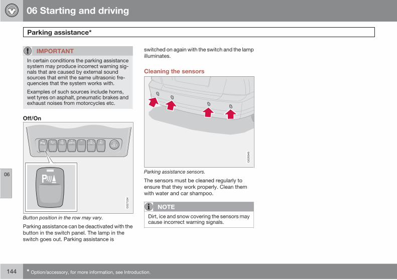
06 Starting and driving
Parking assistance*
06
144 * Option/accessory, for more information, see Introduction.
IMPORTANT
In certain conditions the parking assistancesystem may produce incorrect warning sig-nals that are caused by external soundsources that emit the same ultrasonic fre-quencies that the system works with.
Examples of such sources include horns,wet tyres on asphalt, pneumatic brakes andexhaust noises from motorcycles etc.
Off/OnG
0271
04
Button position in the row may vary.
Parking assistance can be deactivated with the
button in the switch panel. The lamp in the
switch goes out. Parking assistance is
switched on again with the switch and the lamp
illuminates.
Cleaning the sensors
G02
6946
Parking assistance sensors.
The sensors must be cleaned regularly to
ensure that they work properly. Clean them
with water and car shampoo.
NOTE
Dirt, ice and snow covering the sensors maycause incorrect warning signals.
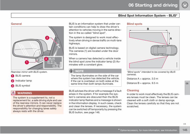
06 Starting and driving
Blind Spot Information System - BLIS*
06
* Option/accessory, for more information, see Introduction. 145
General
G02
0295
Rearview mirror with BLIS system.
BLIS camera
Indicator lamp
BLIS symbol
WARNING
The system is a supplement to, not areplacement for, a safe driving style and useof the rearview mirrors. It can never replacethe driver's attention and responsibility. Theresponsibility for changing lanes safelyalways rests with the driver.
BLIS is an information system that under cer-
tain conditions can help to draw the driver's
attention to vehicles moving in the same direc-
tion in the so-called "blind spot".
The system is designed to work most effec-
tively when driving in dense traffic on multi-lane
highways.
BLIS is based on digital camera technology.
The cameras (1) are located under the door
mirrors.
When a camera has detected a vehicle inside
the blind spot zone the indicator lamp (2) illu-
minates with a constant glow.
NOTE
The lamp illuminates on the side of the carwhere the system has detected the vehicle.If the car is overtaken on both sides at thesame time then both lamps illuminate.
BLIS advises the driver with a message if a fault
arises in the system. If for example the sys-
tem's cameras are obscured then the BLIS
indicator lamp flashes and a message is shown
in the information display. In such cases, check
and clean the lenses. If necessary, the system
can be switched off temporarily by pressing the
BLIS button, see page 146.
Blind spots
A
B
G02
0296
"Blind spots" intended to be covered by BLIScameras.
Distance A = approx. 3.0 m
Distance B = approx. 9.5 m
Cleaning
In order to work most effectively the BLIS cam-
era lenses must be clean. The lenses can be
cleaned with a soft cloth or damp sponge.
Clean the lenses carefully so that they are not
scratched.

06 Starting and driving
Blind Spot Information System - BLIS*
06
146 * Option/accessory, for more information, see Introduction.
IMPORTANT
The lenses are electrically heated to melt iceor snow. If necessary, brush snow awayfrom the lenses.
When BLIS operates
The system operates when the car is driven at
a speed above 10 km/h.
OvertakingThe system is designed to react if you overtake
another vehicle at a speed of up to 10 km/h
faster than the other vehicle.
The system is designed to react if you are over-
taken by a vehicle travelling up to 70 km/h
faster than your vehicle.
WARNING
BLIS does not work in sharp bends.
BLIS does not work when the car is revers-ing.
A wide trailer coupled to the car can concealother vehicles in adjacent lanes. It can pre-vent the vehicle in the screened area frombeing detected by BLIS.
Daylight and darknessIn daylight the system reacts to the shape of
the surrounding vehicles. The system is
designed to detect motor vehicles such as
cars, trucks, buses and motorcycles.
In darkness the system reacts to the head-
lamps of surrounding vehicles. Vehicles with
headlamps that are switched off are not
detected by the system. This means for exam-
ple that the system does not react to a trailer
without headlamps which is towed behind a
car or truck.
WARNING
The system does not react to bicycles ormopeds.
The BLIS cameras can be disrupted byintensive light or when driving in the darkwhen there are no light sources (e.g. streetlighting or other vehicles). The system maythen interpret the lack of light as if the cam-eras have been blocked.
In both cases a message is shown on thedisplay.
When driving in such conditions systemperformance may be temporarily reducedand a text message is shown, seepage 147.
If the message disappears automaticallythen BLIS has returned to normal function-ality.
The BLIS cameras have limitations similar tothe human eye, i.e. they "see" worse inheavy snowfall or thick fog for example.
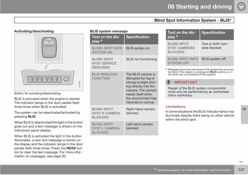
06 Starting and driving
Blind Spot Information System - BLIS*
06
* Option/accessory, for more information, see Introduction. 147
Activating/deactivating
G02
6955
Button for activating/deactivating.
BLIS is activated when the engine is started.
The indicator lamps in the door panels flash
three times when BLIS is activated.
The system can be deactivated/activated by
pressing BLIS.
When BLIS is deactivated the light in the button
goes out and a text message is shown on the
instrument panel display.
When BLIS is activated the light in the button
illuminates, a new text message is shown on
the display and the indicator lamps in the door
panels flash three times. Press the READ but-
ton to clear the text message. For more infor-
mation on messages, see page 50.
BLIS system message
Text on the dis-play A
Specification
BLIND-SPOT INFO
SYSTEM ON
BLIS system on
BLIND-SPOT
SYST SERVICE
REQUIRED
BLIS not functioning
BLIS REDUCED
FUNCTION
The BLIS camera is
disrupted by fog or
strong sunlight shin-
ing directly into the
camera. The camera
resets itself when
the environment has
returned to normal.
BLIND-SPOT
SYST R CAMERA
BLOCKED
Right-hand camera
blocked
BLIND-SPOT
SYST L CAMERA
BLOCKED
Left-hand camera
blocked
Text on the dis-play A
Specification
BLIND-SPOT
SYST CAMERAS
BLOCKED
One or both cam-
eras blocked
BLIND-SPOT INFO
SYSTEM OFF
BLIS system off
A Messages above are only shown if the ignition key is in posi-tion II (or if the engine is running) and BLIS is active (i.e. ifthe driver has not switched off the system).
IMPORTANT
Repair of the BLIS system componentsmust only be performed by an authorisedVolvo workshop.
Limitations
In some situations the BLIS indicator lamp may
illuminate despite there being no other vehicle
within the blind spot.
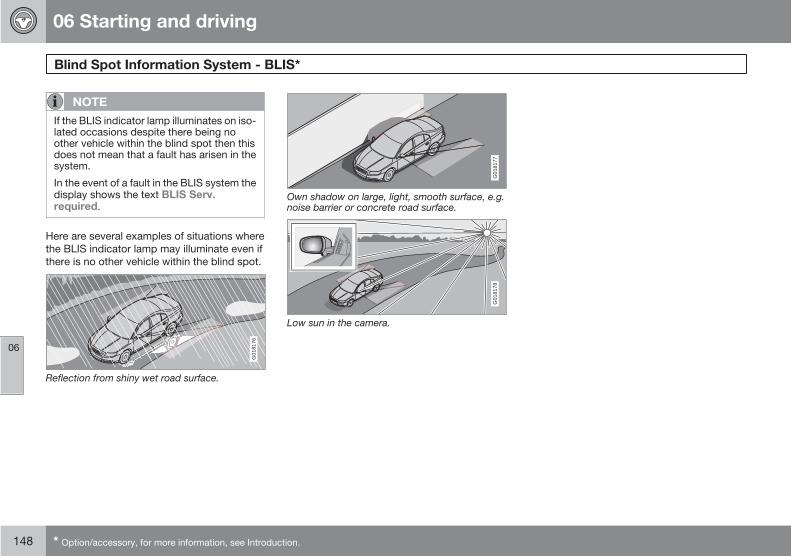
06 Starting and driving
Blind Spot Information System - BLIS*
06
148 * Option/accessory, for more information, see Introduction.
NOTE
If the BLIS indicator lamp illuminates on iso-lated occasions despite there being noother vehicle within the blind spot then thisdoes not mean that a fault has arisen in thesystem.
In the event of a fault in the BLIS system thedisplay shows the text BLIS Serv.required.
Here are several examples of situations where
the BLIS indicator lamp may illuminate even if
there is no other vehicle within the blind spot.G
0181
76
Reflection from shiny wet road surface.
G01
8177
Own shadow on large, light, smooth surface, e.g.noise barrier or concrete road surface.
G01
8178
Low sun in the camera.

06 Starting and driving
Towing and recovery
06
149
Start assistance
Use a donor battery if the battery is discharged
and the engine does not start. Do not tow the
car to bump start it, see page 151.
IMPORTANT
Bump starting the car can damage the cat-alytic converter.
Towing
Find out the highest legal speed for towing
before towing the car.
The car must always be towed facing forward.
1. Unlock the steering wheel lock so that the
car can be steered.
2. For the driver of the towing vehicle: Drive
gently.
For the driver of the vehicle being towed:
Keep the towline taut by holding your foot
gently pressed on the brake pedal in order
to avoid unnecessary jerking.
WARNING
The steering lock stays in the position it wasin when the power was cut off. The steeringlock must be unlocked before towing.
The ignition key must be in position II. Neverremove the ignition key from the ignitionswitch while driving or when the car is beingtowed.
WARNING
The brake servo and power steering do notwork when the engine is switched off. Thebrake pedal must be pressed about fivetimes harder than normal, and the steeringwill be considerably heavier than normal.
Manual gearboxMove gear lever into neutral and release
the parking brake.
Automatic gearboxMove the gear selector to position N and
release the parking brake.
Cars with automatic gearbox must not be
towed at speeds above 80 km/h or further than
80 km.
Towing eyeBefore towing the towing eye must be bolted
securely onto the bumper. The socket and
cover for the towing eye are on the right-hand
side of each bumper.
The towing eye is in the tool kit in the cargo
area.
G02
8528
Proceed as follows:
1. Release the bottom edge of the cover (A)
with a screwdriver or a coin.
2. Screw in the towing eye (B).
06 Starting and driving
Towing and recovery
06
150
3. Screw the eye securely into place up to the
flange (C). You can use a wheel wrench.
• After use, unscrew the towing eye and refitthe cover.
IMPORTANT
On certain cars with fitted towbar the towingeye cannot be secured in the rear mounting.In which case, secure the tow rope in thetowbar. For this reason, it is advisable toalways store the detachable towbar in thecar.
Recovery
The car must always be towed with the wheels
rolling forward.
IMPORTANT
• An all-wheel drive car (AWD) with raisedfront suspension must not be towed atspeeds above 70 km/h. It should not betowed further than 50 km.
WARNING
The towing eye is only designed for towingon roads - not for recovering the car. Call arecovery service for recovery assistance.
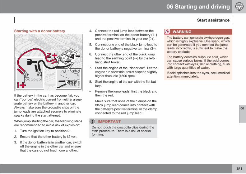
06 Starting and driving
Start assistance
06
151
Starting with a donor battery
G02
0298
If the battery in the car has become flat, you
can "borrow" electric current from either a sep-
arate battery or the battery in another car.
Always make sure the crocodile clips on the
jump leads are attached securely to eliminate
sparks during the start attempt.
When jump starting the car, the following steps
are recommended to avoid risk of explosion:
1. Turn the ignition key to position 0.
2. Ensure that the other battery is 12 volt.
3. If the donor battery is in another car, switch
off the engine in the other car and ensure
that the cars do not touch one another.
4. Connect the red jump lead between the
positive terminal on the donor battery (1+)
and the positive terminal in your car (2+).
5. Connect one end of the black jump lead to
the donor battery's negative terminal (3–).
6. Connect the other end of the black jump
lead to the earthing point (4–) by the left-
hand strut tower.
7. Start the engine of the "donor car". Let the
engine run a few minutes at a speed slightly
higher than idle (1500 rpm).
8. Start the engine of the car with the flat bat-
tery.
Remove the jump leads, first the black and
then the red.
Make sure that none of the clamps on the
black jump lead comes into contact with
the battery's positive terminal or the clamp
connected to the red jump lead.
IMPORTANT
Do not touch the crocodile clips during thestart procedure. There is a risk of sparksforming.
WARNING
The battery can generate oxyhydrogen gas,which is highly explosive. One spark, whichcan be generated if you connect the jumpleads incorrectly, is sufficient to make thebattery explode.
The battery contains sulphuric acid, whichcan cause serious burns. If the acid comesinto contact with eyes, skin or clothing, flushwith large quantities of water.
If acid splashes into the eyes, seek medicalattention immediately.
06 Starting and driving
Driving with a trailer
06
152
General
The load capacity is affected by extra acces-
sories mounted on the car, such as a towbar,
load carriers, space box, the passengers' com-
bined weight etc. as well as towball load. The
load capacity of the car is reduced by the num-
ber of passengers and their weight.
If the towing bracket is fitted by an authorised
Volvo workshop, then the car is delivered with
the necessary equipment for driving with a
trailer.
• The car's towing bracket must be of anapproved type.
• If the towbar is retrofitted, check with yourVolvo dealer that the car is fully equippedfor driving with a trailer.
• Distribute the load on the trailer so that theweight on the towing bracket follows thespecified maximum towball load.
• Increase the tyre pressure to the recom-mended pressure for a full load. For tyrepressure decal location, see page 172.
• Clean the towing bracket regularly and
grease the towball 1.
• Do not tow a heavy trailer when the car isbrand new. Wait until it has been driven atleast 1000 km.
• The brakes are loaded much more thanusual on long and steep downhill slopes.Downshift to a lower gear and adjust yourspeed.
• The engine is loaded more heavily thanusual when driving with a trailer.
• The engine and gearbox can overheat if thecar is driven with a heavy load in hotweather. If the temperature gauge for theengine's cooling system goes into the redzone, stop and let the engine idle for a fewminutes. The automatic gearbox respondsthrough a built-in protection system. Seethe message on the information display. Ifthe car overheats, the air conditioning maybe switched off temporarily.
• In the interests of safety, speed should berestricted to 80 km/h, even if the laws ofcertain countries allow for higher speeds.
• Move the gear selector to park position Pwhen parking an automatic car with ahitched trailer. Always use the parkingbrake. Block the wheels with chocks whenparking a car with hitched trailer on a hill.
Trailer weights
Information on permitted trailer weights, see
page 266.
WARNING
Follow the stated recommendations fortrailer weights. Otherwise, the car and trailermay be difficult to control in the event ofsudden movement and braking.
NOTE
The stated maximum permitted trailerweights are those permitted by Volvo.National vehicle regulations can further limittrailer weights and speeds. Towbars can becertified for higher towing weights than thecar can actually tow.
Automatic gearbox, driving with atrailer
NOTE
Some models require an oil cooler for theautomatic gearbox when driving with atrailer. Check with your nearest Volvo dealeras to what applies to your car if you have aretrofitted towbar.
1 Does not apply to the towball if using a stabiliser hitch.
06 Starting and driving
Driving with a trailer
06
153
Parking on a hill1. Apply the parking brake.
2. Move the gear selector to parking position
P.
Starting on a hill1. Move the gear selector to driving posi-
tion D.
2. Release the parking brake (foot brake
pedal).
Steep inclines
• Select an appropriate manual gear positionwhen climbing steep inclines or at lowspeeds. This prevents the gearbox fromchanging up and keeps the gearbox oilcooler.
• Do not use a higher manual gear than theengine can "handle". It is not always eco-nomical to drive in high gears.
• Avoid driving with a trailer on inclines ofmore than 15 %.
Assisted starting with a trailerCars equipped with a V8 engine have an inte-
grated function which reduces the risk of sig-
nificant jerking and wheelspin when starting
with a trailer hitched to the car.
ActivatingTo activate, the cables from the trailer must be
connected to the trailer socket which is fitted
beside the towbar, see page 154.
DeactivatingUnplug the cables from the electrical socket.
NOTE
The function is also activated when anyother electrical equipment is plugged intothe trailer socket. The car then acceleratesmore gently when pulling away.
Levelling
If your car is equipped with automatic levelling,
the rear suspension always retains the correct
ride height regardless of load. When the car is
stationary, the rear suspension sinks. This is
completely normal. When starting with a load,
the level is pumped up after a certain distance.
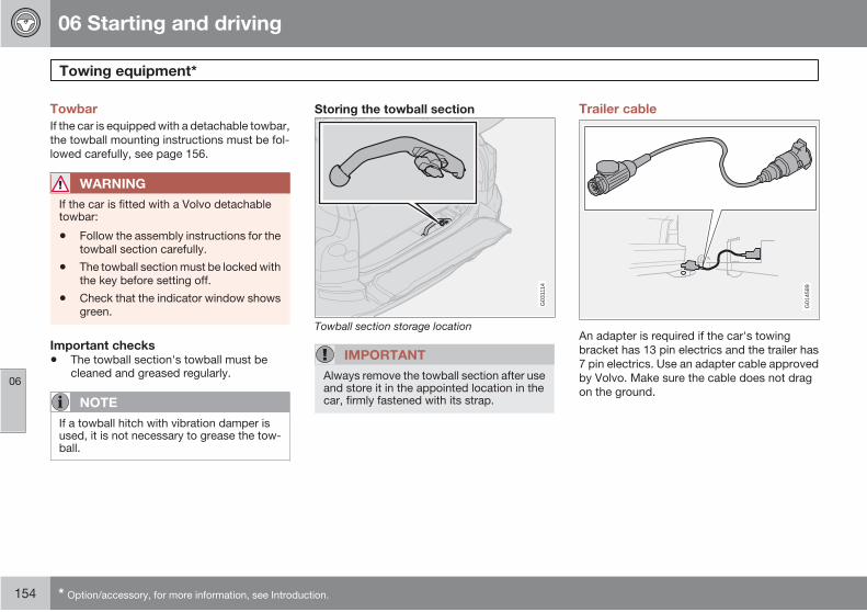
06 Starting and driving
Towing equipment*
06
154 * Option/accessory, for more information, see Introduction.
Towbar
If the car is equipped with a detachable towbar,
the towball mounting instructions must be fol-
lowed carefully, see page 156.
WARNING
If the car is fitted with a Volvo detachabletowbar:
• Follow the assembly instructions for thetowball section carefully.
• The towball section must be locked withthe key before setting off.
• Check that the indicator window showsgreen.
Important checks
• The towball section's towball must becleaned and greased regularly.
NOTE
If a towball hitch with vibration damper isused, it is not necessary to grease the tow-ball.
Storing the towball section
G03
1114
Towball section storage location
IMPORTANT
Always remove the towball section after useand store it in the appointed location in thecar, firmly fastened with its strap.
Trailer cable
G01
4589
An adapter is required if the car's towing
bracket has 13 pin electrics and the trailer has
7 pin electrics. Use an adapter cable approved
by Volvo. Make sure the cable does not drag
on the ground.

06 Starting and driving
Towing equipment*
06
* Option/accessory, for more information, see Introduction. 155
Specifications
G02
6682 G
0271
08
G02
7109
Dimensions for mounting points (mm)
A B C D E F G
Fixed or detachable towbar 1110 85 1081 541 122 50 354
1 Side member
2 Ball centre
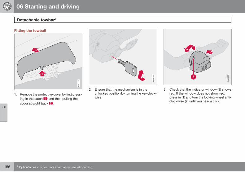
06 Starting and driving
Detachable towbar*
06
156 * Option/accessory, for more information, see Introduction.
Fitting the towball
G01
7317
1. Remove the protective cover by first press-
ing in the catch and then pulling the
cover straight back .
G02
0301
2. Ensure that the mechanism is in the
unlocked position by turning the key clock-
wise.
G02
0302
3. Check that the indicator window (3) shows
red. If the window does not show red,
press in (1) and turn the locking wheel anti-
clockwise (2) until you hear a click.

06 Starting and driving
Detachable towbar*
06
* Option/accessory, for more information, see Introduction. 157
G02
0304
4. Insert the towball section until you hear a
click.
G02
0306
5. Check that the indicator window shows
green.
G02
0307
6. Turn the key anticlockwise to locked posi-
tion. Remove the key from the lock.
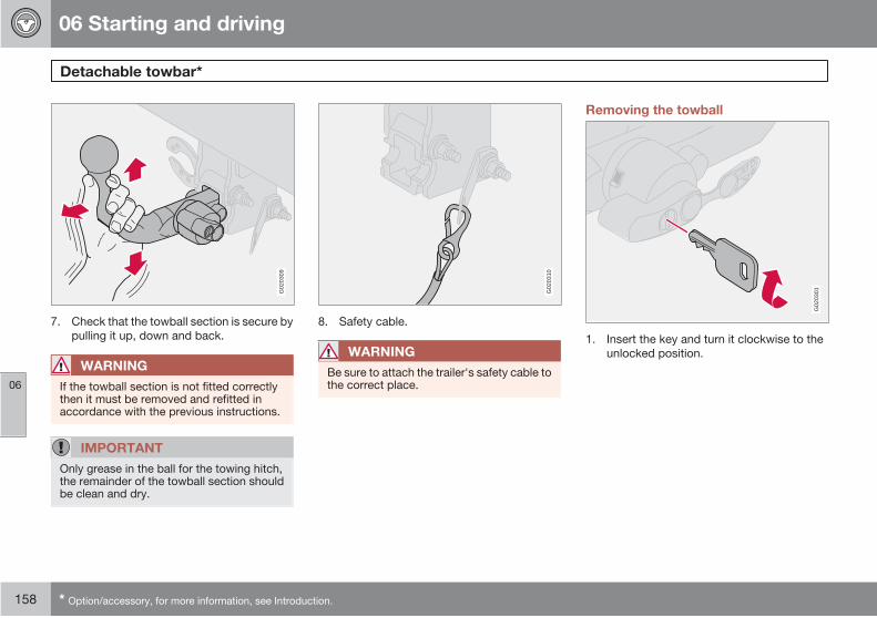
06 Starting and driving
Detachable towbar*
06
158 * Option/accessory, for more information, see Introduction.
G02
0309
7. Check that the towball section is secure by
pulling it up, down and back.
WARNING
If the towball section is not fitted correctlythen it must be removed and refitted inaccordance with the previous instructions.
IMPORTANT
Only grease in the ball for the towing hitch,the remainder of the towball section shouldbe clean and dry.
G02
0310
8. Safety cable.
WARNING
Be sure to attach the trailer's safety cable tothe correct place.
Removing the towball
G02
0301
1. Insert the key and turn it clockwise to the
unlocked position.

06 Starting and driving
Detachable towbar*
06
* Option/accessory, for more information, see Introduction. 159
G02
0312
2. Push in the locking wheel (1) and turn it
anticlockwise (2) until you hear a click.
G02
0314
3. Turn the locking wheel down fully, until it
comes to a stop. Hold it in this position
while pulling the towball rearward and
upward.
WARNING
Secure the towbar's loose towball safely ifit is stored in the car, see page 154.
G01
7318
4. Push on the protective cover.

06 Starting and driving
Loading
06
160
General
The load capacity is affected by extra acces-
sories mounted on the car, such as load carri-
ers, space box and towbar, as well as the load
on the towball. The load capacity of the car is
reduced by the number of passengers and their
weight. For information on permitted weights,
see page 266.
For more information on the cargo area, see
page 105
WARNING
The car's driving characteristics changedepending on how heavily it is loaded andhow the load is distributed.
Load on the roof
Load carriersLoad carriers designed by Volvo are recom-
mended in order to avoid damaging the car and
for maximum possible safety while driving.
Carefully follow the mounting instructions
enclosed with the load carriers.
• Check periodically that the load carriersand load are properly secured. Lash theload securely with retaining straps.
• Distribute the load evenly over the loadcarriers. Put the heaviest objects at thebottom.
• The size of the area exposed to the wind,and therefore fuel consumption, increasewith the load's size.
• Drive gently. Avoid quick acceleration,heavy braking and hard cornering.
WARNING
Load no more than 100 kg on the roof, inclu-sive of the load carriers or space box. Thecar's centre of gravity and driving characte-ristics are altered by roof loads.
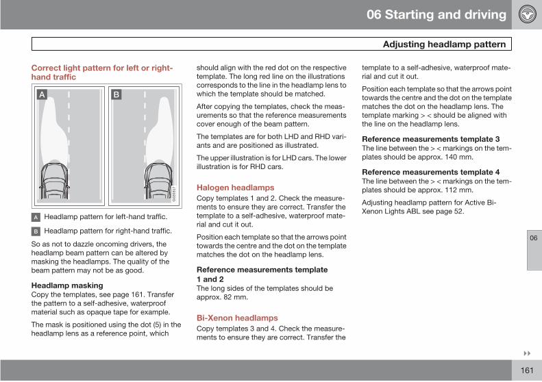
06 Starting and driving
Adjusting headlamp pattern
06
161
Correct light pattern for left or right-hand traffic
G02
0317
Headlamp pattern for left-hand traffic.
Headlamp pattern for right-hand traffic.
So as not to dazzle oncoming drivers, the
headlamp beam pattern can be altered by
masking the headlamps. The quality of the
beam pattern may not be as good.
Headlamp maskingCopy the templates, see page 161. Transfer
the pattern to a self-adhesive, waterproof
material such as opaque tape for example.
The mask is positioned using the dot (5) in the
headlamp lens as a reference point, which
should align with the red dot on the respective
template. The long red line on the illustrations
corresponds to the line in the headlamp lens to
which the template should be matched.
After copying the templates, check the meas-
urements so that the reference measurements
cover enough of the beam pattern.
The templates are for both LHD and RHD vari-
ants and are positioned as illustrated.
The upper illustration is for LHD cars. The lower
illustration is for RHD cars.
Halogen headlamps
Copy templates 1 and 2. Check the measure-
ments to ensure they are correct. Transfer the
template to a self-adhesive, waterproof mate-
rial and cut it out.
Position each template so that the arrows point
towards the centre and the dot on the template
matches the dot on the headlamp lens.
Reference measurements template
1 and 2The long sides of the templates should be
approx. 82 mm.
Bi-Xenon headlamps
Copy templates 3 and 4. Check the measure-
ments to ensure they are correct. Transfer the
template to a self-adhesive, waterproof mate-
rial and cut it out.
Position each template so that the arrows point
towards the centre and the dot on the template
matches the dot on the headlamp lens. The
template marking > < should be aligned with
the line on the headlamp lens.
Reference measurements template 3The line between the > < markings on the tem-
plates should be approx. 140 mm.
Reference measurements template 4The line between the > < markings on the tem-
plates should be approx. 112 mm.
Adjusting headlamp pattern for Active Bi-
Xenon Lights ABL see page 52.
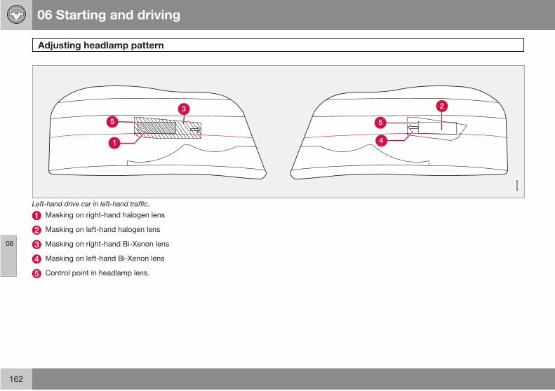
06 Starting and driving
Adjusting headlamp pattern
06
162
G03
0200
Left-hand drive car in left-hand traffic.
Masking on right-hand halogen lens
Masking on left-hand halogen lens
Masking on right-hand Bi-Xenon lens
Masking on left-hand Bi-Xenon lens
Control point in headlamp lens.

06 Starting and driving
Adjusting headlamp pattern
06
163
G03
0201
Right-hand drive car in right-hand traffic.
Masking on left-hand halogen lens
Masking on right-hand halogen lens
Masking on left-hand Bi-Xenon lens
Masking on right-hand Bi-Xenon lens
Control point in headlamp lens.
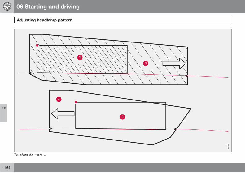
06 Starting and driving
Adjusting headlamp pattern
06
164
G02
7103
Templates for masking.

06 Starting and driving
06
165
G02
0918
166 * Option/accessory, for more information, see Introduction.
General.................................................................................................. 168
Tyre pressure........................................................................................ 171
Warning triangle* and spare wheel*...................................................... 173
Changing wheels................................................................................... 176
178
Emergency puncture repair*................................................................. 180
Tyre pressure monitoring.......................................................................

07WHEELS AND TYRES
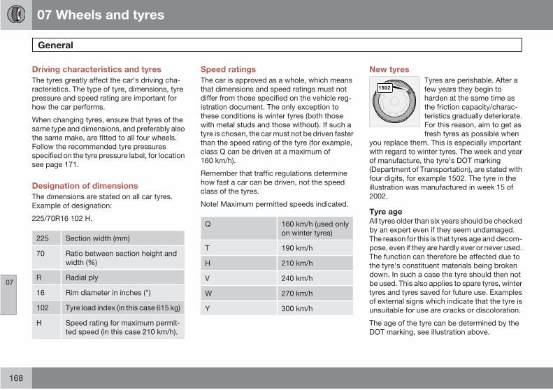
07 Wheels and tyres
General
07
168
Driving characteristics and tyres
The tyres greatly affect the car's driving cha-
racteristics. The type of tyre, dimensions, tyre
pressure and speed rating are important for
how the car performs.
When changing tyres, ensure that tyres of the
same type and dimensions, and preferably also
the same make, are fitted to all four wheels.
Follow the recommended tyre pressures
specified on the tyre pressure label, for location
see page 171.
Designation of dimensions
The dimensions are stated on all car tyres.
Example of designation:
225/70R16 102 H.
225 Section width (mm)
70 Ratio between section height and
width (%)
R Radial ply
16 Rim diameter in inches (")
102 Tyre load index (in this case 615 kg)
H Speed rating for maximum permit-
ted speed (in this case 210 km/h).
Speed ratings
The car is approved as a whole, which means
that dimensions and speed ratings must not
differ from those specified on the vehicle reg-
istration document. The only exception to
these conditions is winter tyres (both those
with metal studs and those without). If such a
tyre is chosen, the car must not be driven faster
than the speed rating of the tyre (for example,
class Q can be driven at a maximum of
160 km/h).
Remember that traffic regulations determine
how fast a car can be driven, not the speed
class of the tyres.
Note! Maximum permitted speeds indicated.
Q 160 km/h (used only
on winter tyres)
T 190 km/h
H 210 km/h
V 240 km/h
W 270 km/h
Y 300 km/h
New tyres
Tyres are perishable. After a
few years they begin to
harden at the same time as
the friction capacity/charac-
teristics gradually deteriorate.
For this reason, aim to get as
fresh tyres as possible when
you replace them. This is especially important
with regard to winter tyres. The week and year
of manufacture, the tyre's DOT marking
(Department of Transportation), are stated with
four digits, for example 1502. The tyre in the
illustration was manufactured in week 15 of
2002.
Tyre ageAll tyres older than six years should be checked
by an expert even if they seem undamaged.
The reason for this is that tyres age and decom-
pose, even if they are hardly ever or never used.
The function can therefore be affected due to
the tyre's constituent materials being broken
down. In such a case the tyre should then not
be used. This also applies to spare tyres, winter
tyres and tyres saved for future use. Examples
of external signs which indicate that the tyre is
unsuitable for use are cracks or discoloration.
The age of the tyre can be determined by the
DOT marking, see illustration above.

07 Wheels and tyres
General
07
169
More even wear and maintenance
G02
0323
The correct tyre pressure results in more even
wear, see page 172. Driving style, tyre pres-
sure, climate and road condition affect how
quickly your tyres age and wear. To avoid dif-
ferences in tread depth and to prevent wear
patterns arising, the front and rear wheels can
be switched with each other. A suitable dis-
tance for the first change is approx. 5000 km
and then at 10 000 km intervals. Contact an
authorised Volvo workshop if you are uncertain
about tread depth.
Wheels should be stored lying down or hanging
up, and not standing up.
Tyres with tread wear indicatorsTread wear indicators are narrow treadless
bands across the width of the tread. On the
side of the tyre are the letters TWI (Tread Wear
Indicator). When the tyre's tread depth is down
to 1.6 mm, the tread depth will be level in height
with the tread wear indicators. Change to new
tyres as soon as possible. Remember that
tyres with little tread depth provide very poor
grip in rain and snow.
Winter tyres
Volvo recommends winter tyres with specific
winter tyre dimensions. Tyre dimensions are
dependent on engine variant. When driving on
winter tyres, they must be fitted to all four
wheels.
NOTE
Ask a Volvo dealer which rim and tyre typesare most suitable.
Studded tyresStudded winter tyres should be run in gently for
500 – 1000 km so the studs settle properly into
the tyre. This gives the tyre, and especially the
studs, a longer service life.
NOTE
The legal provisions for the use of studdedtyres vary from country to country.
Tread depthRoad conditions with ice, slush and low tem-
peratures place considerably higher demands
on tyres than summer conditions. It is therefore
recommended not to drive on winter tyres that
have a tread depth of less than four millimetres.
Snow chainsSnow chains may only be used on the front
wheels. This also applies to all-wheel-drive
cars.
Never drive faster than 50 km/h with snow
chains. Avoid driving on bare ground as this
wears out both the snow chains and tyres.
Never use quick-fit snow chains as the space
between the brake discs and the wheels is too
small.
IMPORTANT
Use Volvo genuine snow chains or equiva-lent chains designed for the car model, andtyre and rim dimensions. Consult an author-ised Volvo workshop
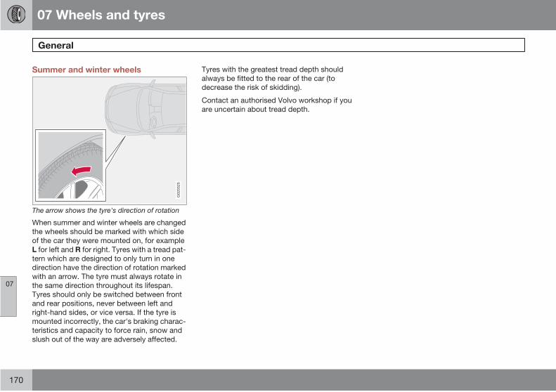
07 Wheels and tyres
General
07
170
Summer and winter wheels
G02
0325
The arrow shows the tyre's direction of rotation
When summer and winter wheels are changed
the wheels should be marked with which side
of the car they were mounted on, for example
L for left and R for right. Tyres with a tread pat-
tern which are designed to only turn in one
direction have the direction of rotation marked
with an arrow. The tyre must always rotate in
the same direction throughout its lifespan.
Tyres should only be switched between front
and rear positions, never between left and
right-hand sides, or vice versa. If the tyre is
mounted incorrectly, the car's braking charac-
teristics and capacity to force rain, snow and
slush out of the way are adversely affected.
Tyres with the greatest tread depth should
always be fitted to the rear of the car (to
decrease the risk of skidding).
Contact an authorised Volvo workshop if you
are uncertain about tread depth.

07 Wheels and tyres
Tyre pressure
07
171
Recommended tyre pressure
G02
0791
The tyre pressure label on the driver's side door
pillar shows which pressures the tyres should
have at different loads and speed conditions.
Stated on the decal:
• Tyre pressures for the car's recommendedwheel size
• ECO pressure
• Spare wheel pressure (Temporary Spare).
Checking the tyre pressureCheck the tyre pressure regularly.
NOTE
Tyre pressure decreases over time, this is anatural phenomenon. Tyre pressure alsovaries depending on ambient temperature.
Even after several kilometres of driving, the
tyres warm up and the pressure increases. So
air must not be released if the pressure is
checked when the tyres are warm. While the
pressure must be increased if it is too low.
Inadequately inflated tyres increase fuel con-
sumption, shorten tyre lifespan and impair the
car's roadholding. Driving on tyres with tyre
pressure that is too low can also result in the
tyres overheating and disintegrating.
For information on the correct tyre pressure,
see page 172. The specified tyre pressures
refer to "cold tyres". ("Cold tyres" means the
tyres are the same temperature as the ambient
temperature.)
Fuel economy, ECO pressureAt speeds under 160 km/h, the general tyre
pressure for full load is recommended in order
to obtain optimum fuel economy.
Tyre pressure affects travelling comfort, road
noise and steering characteristics.

07 Wheels and tyres
Tyre pressure
07
172
Tyre pressure table
Variant Tyre size Speed (km/h) A Load, 1-3 persons Max. load
Front (kPa) Rear (kPa) Front (kPa) Rear (kPa)
All 225/70R16
235/65R17
235/60R18
0-160 220 220 270 270
160+ 220 220 270 270
255/50R19
255/45R20
0-160 240 240 270 270
160 + 240 240 270 270
All All 0-160 270 B 270B 270B 270B
Spare wheel
Temporary spare
T125/85R16 99M 0-80 420 420 420 420
A In certain countries there is the "bar" unit beside the SI unit "Pascal": 1 bar = 100 kPa (270 kPa = 2.70 bar)B ECO pressure see page 171.
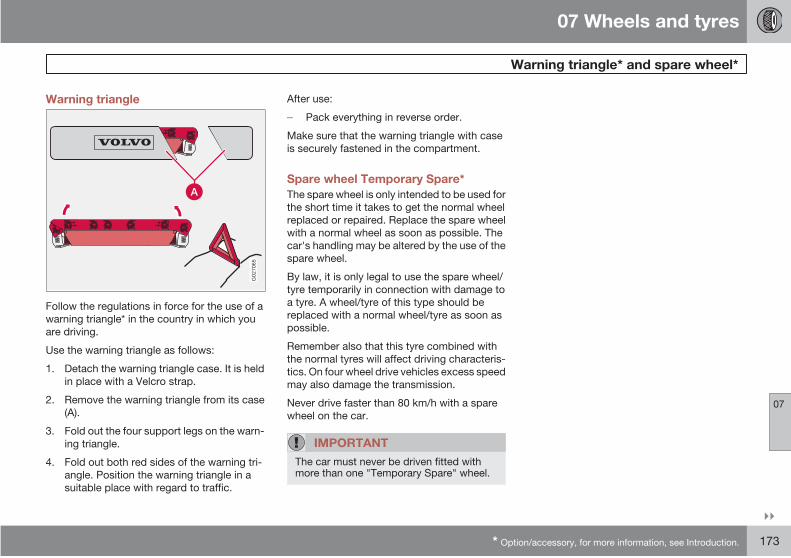
07 Wheels and tyres
Warning triangle* and spare wheel*
07
* Option/accessory, for more information, see Introduction. 173
Warning triangle
G02
7065
Follow the regulations in force for the use of a
warning triangle* in the country in which you
are driving.
Use the warning triangle as follows:
1. Detach the warning triangle case. It is held
in place with a Velcro strap.
2. Remove the warning triangle from its case
(A).
3. Fold out the four support legs on the warn-
ing triangle.
4. Fold out both red sides of the warning tri-
angle. Position the warning triangle in a
suitable place with regard to traffic.
After use:
Pack everything in reverse order.
Make sure that the warning triangle with case
is securely fastened in the compartment.
Spare wheel Temporary Spare*
The spare wheel is only intended to be used for
the short time it takes to get the normal wheel
replaced or repaired. Replace the spare wheel
with a normal wheel as soon as possible. The
car's handling may be altered by the use of the
spare wheel.
By law, it is only legal to use the spare wheel/
tyre temporarily in connection with damage to
a tyre. A wheel/tyre of this type should be
replaced with a normal wheel/tyre as soon as
possible.
Remember also that this tyre combined with
the normal tyres will affect driving characteris-
tics. On four wheel drive vehicles excess speed
may also damage the transmission.
Never drive faster than 80 km/h with a spare
wheel on the car.
IMPORTANT
The car must never be driven fitted withmore than one "Temporary Spare" wheel.

07 Wheels and tyres
Warning triangle* and spare wheel*
07
174 * Option/accessory, for more information, see Introduction.
Spare wheel – removing
G02
6998
The spare wheel is located under the car. The
jack*, tool kit* and crank are located under the
floor hatch. The crank is in two parts. One part
is in the tool kit, and the other is under the tool
kit.
NOTE
There is a puller spanner in the tool kit toremove the hub cap (certain wheel options).
The location of the jack varies:
Cars seating seven
Cars seating five
Proceed as follows to release the spare wheel:
1. Lower the bottom of the tailgate and lift up
the floor hatch in the cargo area.
2. Take the two parts of the crank and assem-
ble.
3. Fit the crank in the winch.
4. Loosen the tyre by cranking anticlockwise
until you reach the stop.
NOTE
The cable could damage the car if it hangsfree while driving.
5. Release the wheel from the cable and wind
up the cable clockwise.
6. Place the punctured tyre in the cargo area.
The tool kit contains a plastic bag for the
tyre.

07 Wheels and tyres
Warning triangle* and spare wheel*
07
* Option/accessory, for more information, see Introduction. 175
NOTE
The spot under the car is only intended forthe car's original spare wheel. Do not placeany other wheels there.
Spare wheel – refitting
It is best to have two people put the spare
wheel back in place. One person to crank and
the other to guide the wheel.
1. Crank out the cable and place its anchor in
the centre hole of the wheel.
2. Slowly crank (clockwise) the cable in a bit.
3. Angle the wheel so that it comes in over the
exhaust system.
4. Hold down the rear edge of the wheel while
cranking it in.
5. Place the wheel above the rear axle,
against the floor.
6. Crank to the stop point.
7. Check that the wheel is properly secured.
WARNING
Check that the right mounting points arebeing used. A production anchorage withpin is located between the jacking points.This is not strong enough to use to lift thecar. If you are unsure about the location ofthe jacking points, contact an authorisedVolvo workshop. An incorrectly fitted jackcould damage the door and body.
Tools - returning into placeThe tools and jack* must be returned to their
correct places after use. The jack must be
cranked to the correct position, see the pre-
ceding illustration, in order to have space.
IMPORTANT
Tools and jack must be stored in theintended location in the car's cargo areawhen not in use.
First aid*
A case with first aid equipment is located in the
cargo area.
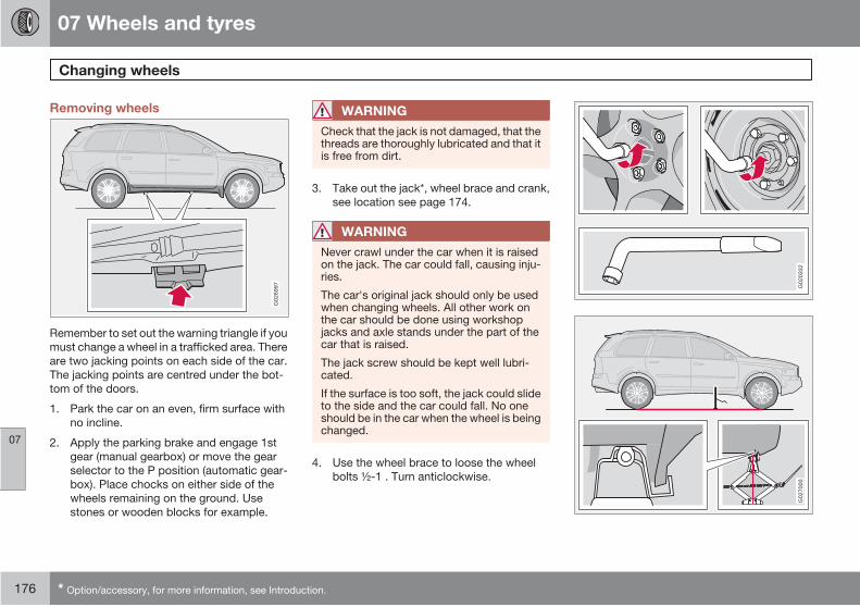
07 Wheels and tyres
Changing wheels
07
176 * Option/accessory, for more information, see Introduction.
Removing wheels
G02
6997
Remember to set out the warning triangle if you
must change a wheel in a trafficked area. There
are two jacking points on each side of the car.
The jacking points are centred under the bot-
tom of the doors.
1. Park the car on an even, firm surface with
no incline.
2. Apply the parking brake and engage 1st
gear (manual gearbox) or move the gear
selector to the P position (automatic gear-
box). Place chocks on either side of the
wheels remaining on the ground. Use
stones or wooden blocks for example.
WARNING
Check that the jack is not damaged, that thethreads are thoroughly lubricated and that itis free from dirt.
3. Take out the jack*, wheel brace and crank,
see location see page 174.
WARNING
Never crawl under the car when it is raisedon the jack. The car could fall, causing inju-ries.
The car's original jack should only be usedwhen changing wheels. All other work onthe car should be done using workshopjacks and axle stands under the part of thecar that is raised.
The jack screw should be kept well lubri-cated.
If the surface is too soft, the jack could slideto the side and the car could fall. No oneshould be in the car when the wheel is beingchanged.
4. Use the wheel brace to loose the wheel
bolts ½-1 . Turn anticlockwise.
G02
0332
G02
7000
07 Wheels and tyres
Changing wheels
07
177
WARNING
Never position anything between theground and the jack, nor between the jack-ing point and the jack.
WARNING
If the jack is positioned incorrectly, the carcould fall. Risk of injury.
5. Place the jack under the jacking point and
crank it up towards the car floor. There is
an recess in the plastic cover at each
anchorage point. Check that the jack sits
securely in the anchorage. Then adjust the
jack so that its foot is positioned vertically
under the anchorage. See illustration.
6. Lift the car until the wheel is free.
7. Remove the wheel bolts and lift off the
wheel.
Fitting the wheel
1. Clean the contract surfaces on the wheel
and hub.
2. Put on the wheel. Screw in the wheel bolts.
3. Lower the car so that the wheel cannot
rotate.
4. Tighten the wheel bolts alternately and in
torque steps. Tightening torque: 140 Nm
(14.0 kpm). It is important that they are
tightened to the correct torque. Check with
a torque wrench.
5. Screw the jack all the way down before
returning it to the cargo area. Then secure
it in place.
6. Check that the new tyre has the correct
amount of pressure.
NOTE
This wheel bolt may also be used for steelwheel rims.
Make sure to use the correct type of bolt. If you
are unsure, check with the nearest Volvo work-
shop.
IMPORTANT
If TPMS is specified then the tyres must becalibrated after fitting, see page 178

07 Wheels and tyres
07
178 * Option/accessory, for more information, see Introduction.
General*
Tyre pressure monitoring, TPMS (Tyre Pres-
sure Monitoring System) warns the driver when
the pressure is too low in one or more of the
car's tyres. It uses sensors located inside the
air valve in each wheel. When the car is driven
at about 40 km/h the system detects the tyre
pressure. If the pressure is too low then a warn-
ing lamp on the instrument panel illuminates
and a message is shown on the display.
Always check the system after changing a
wheel in order to ensure that replacement
wheels work with the system.
For information on correct tyre pressures, see
page 171 and see page 172.
The TPMS system does not replace normal
tyre maintenance.
IMPORTANT
If a fault should arise in the tyre pressuresystem a warning lamp on the instrumentpanel will illuminate. The message TYREPRESS. SYST SERVICE REQUIRED willbe shown. This can be for various reasons,e.g. fitting a wheel not equipped with a sen-sor adapted for Volvo's tyre pressure moni-toring system.
Adjusting tyre pressure monitoringTyre pressure monitoring can be adjusted in
order to follow Volvo's tyre pressure recom-
mendations, when driving with a heavy load for
example.
NOTE
The engine must not be running.
1. Inflate the tyres to the required pressure.
2. Select key position I or II.
3. Turn the thumbwheel on the left-hand stalk
switch until the text TYRE PRESSURE
CALIBRATION is shown on the display.
4. Press and hold the RESET button until the
text TYRE PRESSURE CALIBRATED is
shown.
Rectifying low tyre pressureWhen the message LOW TYRE PRESS.
CHECK TYRES is shown on the display:
1. Check the tyre pressure in all four tyres.
2. Inflate the tyre(s) to the correct pressure.
3. Drive the car for at least 1 minute in total at
a minimum of 40 km/h and check that the
message disappears.
Deactivating tyre pressure monitoring
NOTE
The engine must not be running.
1. Key position I or II.
2. Turn the thumbwheel on the left-hand stalk
switch until the text TYRE PRESS. SYST
ON is shown on the display.
3. Press and hold the RESET button until the
text TYRE PRESS. SYST OFF is shown.
To reactivate the system repeat the same steps
1-3, so that TYRE PRESS. SYST ON is shown
on the display.
RecommendationsOnly factory fitted wheels are equipped with
TPMS sensors in the valves.
• The temporary spare wheel does not havethis sensor.
• If wheels without TPMS sensors are usedthen TYRE PRESS SYST SERVICEREQUIRED will be shown every time thecar is driven faster than 40 km/h for morethan 10 minutes.
Tyre pressure monitoring

07 Wheels and tyres
07
179
• Volvo recommends that TPMS sensors arefitted to all wheels on the car (summer andwinter wheels).
• Volvo recommends that sensors are notmoved between different wheels.
WARNING
When inflating a tyre equipped with TPMS,hold the nozzle of the pump directly againstthe valve to avoid damaging the valve.
Tyre pressure monitoring

07 Wheels and tyres
Emergency puncture repair*
07
180 * Option/accessory, for more information, see Introduction.
General
The emergency puncture repair kit is used to
seal a puncture as well as to check and adjust
the tyre pressure. It consists of a compressor
and a bottle with sealing fluid. The kit works as
a temporary repair. The sealing fluid bottle
must be replaced before its expiration date and
after use.
The sealing fluid effectively seals tyres punc-
tured in the tread.
NOTE
The emergency puncture repair kit is onlyintended for sealing tyres with a puncture inthe tread.
NOTE
The jack is an option on cars equipped withemergency puncture repair kit.
The emergency puncture repair kit has limited
capacity to seal tyres which have punctures in
the wall. Do not seal tyres with the emergency
puncture repair kit if they have larger slits,
cracks or similar damage.
12 V sockets for connecting the compressor
are located by the centre console in the front,
by the rear seat and in the cargo area. Choose
the electrical socket that is nearest the punc-
tured tyre.
WARNING
You should not drive faster than 80 km/hafter the emergency tyre repair kit has beenused. Contact an authorised Volvo work-shop for inspection of the sealed tyre (maxi-mum driving distance is 200 km). The staffthere can determine whether or not the tyrecan be repaired or if it needs to be replaced.
Taking out the emergency puncture
repair kitThe emergency puncture repair kit, with com-
pressor and tools, is located under the floor in
the cargo area.
1. Fold away the rear edge of the floor mat,
forward from the back.
2. Lift up the emergency puncture repair kit.
Overview
G02
0400
Label, maximum permitted speed
Switch
Cable
Bottle holder (orange cap)
Protective cap
Pressure reducing valve
Air hose
Sealing fluid bottle
Pressure gauge
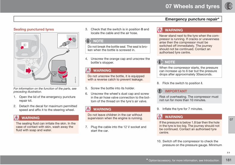
07 Wheels and tyres
Emergency puncture repair*
07
* Option/accessory, for more information, see Introduction. 181
Sealing punctured tyres
G01
9723
For information on the function of the parts, seepreceding illustration.
1. Open the lid of the emergency puncture
repair kit.
2. Detach the decal for maximum permitted
speed and affix it to the steering wheel.
WARNING
The sealing fluid can irritate the skin. In thecase of contact with skin, wash away thefluid with soap and water.
3. Check that the switch is in position 0 and
locate the cable and the air hose.
NOTE
Do not break the bottle seal. The seal is bro-ken when the bottle is screwed in.
4. Unscrew the orange cap and unscrew the
bottle's stopper.
WARNING
Do not unscrew the bottle, it is equippedwith a reverse catch to prevent leakage.
5. Screw the bottle into its holder.
6. Unscrew the wheel's dust cap and screw
in the air hose valve connection to the bot-
tom of the thread on the tyre's air valve.
WARNING
Do not leave children in the car withoutsupervision when the engine is running.
7. Plug the cable into the 12 V socket and
start the car.
WARNING
Never stand next to the tyre when the com-pressor is running. If cracks or unevennessarise then the compressor must beswitched off immediately. The journeyshould not be continued. Contact anauthorised tyre centre.
NOTE
When the compressor starts, the pressurecan increase up to 6 bar but the pressuredrops after approximately 30seconds.
8. Flick the switch to position I.
IMPORTANT
Risk of overheating. The compressor mustnot run for more than 10 minutes.
9. Inflate the tyre for 7 minutes.
WARNING
If the pressure is below 1.8 bar then the holein the tyre is too big. The journey should notbe continued. Contact an authorised tyrecentre.
10. Switch off the compressor to check the
pressure on the pressure gauge. Minimum
07 Wheels and tyres
Emergency puncture repair*
07
182 * Option/accessory, for more information, see Introduction.
pressure is 1.8 bar and maximum is
3.5 bar.
11. Switch off the compressor and unplug the
cable from the 12 V socket.
12. Detach the hose from the tyre valve and fit
the valve cap.
13. As soon as possible, drive approximately 3
km at a maximum speed of 80 km/h so that
the sealing fluid can seal the tyre.
Rechecking the repair and pressure1. Reconnect the equipment.
2. Read the tyre pressure on the pressure
gauge.
3. If it is below 1.3 bar then the tyre is insuf-
ficiently sealed. The journey should not be
continued. Contact a tyre centre.
4. If the tyre pressure is higher than 1.3 bar,
the tyre must be inflated to the pressure
specified on the tyre pressure decal.
Release air using the pressure reducing
valve if the tyre pressure is too high.
WARNING
Do not unscrew the bottle, it is equippedwith a reverse catch to prevent leakage.
5. Switch off the compressor. Detach the air
hose and cable. Refit the dust cap.
NOTE
The sealing fluid bottle and hose must bereplaced after use. Replacement must beperformed by an authorised Volvo work-shop.
WARNING
Check the tyre pressure regularly.
6. Return the emergency puncture repair kit
to the cargo area.
7. Drive to the nearest authorised Volvo work-
shop for the replacement/repair of the
damaged tyre. Advise the workshop that
the tyre contains sealing fluid.
WARNING
You should not drive faster than 80 km/hafter the emergency tyre repair kit has beenused. Contact an authorised Volvo work-shop for inspection of the sealed tyre (maxi-mum driving distance is 200 km). The staffthere can determine whether or not the tyrecan be repaired or if it needs to be replaced.
Inflating the tyres
The car's original tyres can be inflated by the
compressor.
1. The compressor must be switched off.
Make sure that the switch is in position 0
and locate the cable and air hose.
2. Unscrew the wheel's dust cap and screw
in the air hose valve connection to the bot-
tom of the thread on the tyre's air valve.
WARNING
Do not leave children in the car withoutsupervision when the engine is running.
WARNING
Inhaling car exhaust fumes can result indanger to life. Never leave the engine run-ning in sealed areas or areas that lack suf-ficient ventilation.
3. Connect the cable to one of the car's 12 V
sockets and start the car.
4. Start the compressor by flicking the switch
to position I.
07 Wheels and tyres
Emergency puncture repair*
07
* Option/accessory, for more information, see Introduction. 183
IMPORTANT
Risk of overheating. The compressor mustnot run for more than 10 minutes.
5. Inflate the tyre to the pressure specified on
the tyre pressure decal. (Release air using
the pressure reducing valve if the tyre pres-
sure is too high.)
6. Switch off the compressor. Detach the air
hose and cable.
7. Refit the dust cap.
Changing the sealing fluid canister
Replace the bottle when the expiration date
has passed. Treat the old bottle as environ-
mentally hazardous waste.
WARNING
The bottle contains 1.2-Ethanol and naturalrubber-latex.
Harmful if ingested. Could result in allergicreaction in the event of skin contact.
Avoid contact with the skin and eyes.
Store out of the reach of children.
NOTE
Leave the container at a collection point forstoring dangerous waste.
G02
0920
184
Cleaning................................................................................................ 186
Touching up paintwork......................................................................... 189
Rustproofing......................................................................................... 190

08CAR CARE
08 Car care
Cleaning
08
186
Washing the car
Wash the car as soon as it becomes dirty. Use
car shampoo. Dirt and road salt can lead to
corrosion.
• Do not park the car in direct sunlight.Washing a car with hot paintwork cancause permanent paintwork damage.Wash the car in a car wash with wastewater separator.
• Thoroughly rinse dirt off the underbody ofthe car.
IMPORTANT
Rinse the entire car to remove loose dirt.When using a pressure washer: Make surethat the nozzle of the pressure washer is notcloser than 30 cm to the bodywork. Do notspray directly onto the locks.
• Wash using a sponge, car shampoo andplenty of lukewarm water.
• If the dirt is difficult to dislodge, wash thecar using a cold degreasing agent.
• Dry the car using a clean, soft chamois ora water scraper.
WARNING
Always have the engine cleaned by a work-shop. There is a risk of fire if the engine ishot.
IMPORTANT
Dirty headlamps have impaired functional-ity. Clean them regularly, when refuelling forexample.
NOTE
Outside lighting such as headlamps, foglamps and rear lamps may temporarily havecondensation on the inside of the lens. Thisis a natural phenomenon, all outside lightingis designed to withstand this. Condensationis normally vented out of the lamp when ithas been switched on for a time.
Cleaning the wiper bladesAsphalt, dust and salt residue on wiper blades,
as well as insects, ice etc. on the windscreen,
impair the service life of wiper blades.
NOTE
Wash the wiper blades and windscreen reg-ularly with lukewarm soap solution or carshampoo.
Do not use any strong solvents.
Removing bird droppingsWash away bird droppings from the paintwork
as soon as possible. Bird droppings contain
chemicals that affect and discolour paintwork
very quickly. This discoloration can only be
removed by a specialist.
Chromed wheels
IMPORTANT
Rim cleaning agents can cause stains onchrome-plated wheels. Wash using asponge, car shampoo and plenty of luke-warm water.
Automatic car washesAn automatic car wash is a simple and quick
way of washing the car, but it can never replace
a proper handwashing. The brushes of an auto-
matic car wash cannot reach everywhere.
IMPORTANT
Washing by hand is gentler to the paintworkthan an automatic car wash. Paintwork isalso more sensitive when it is new. For thisreason, handwashing is recommended dur-ing the first few months with a new car.

08 Car care
Cleaning
08
* Option/accessory, for more information, see Introduction. 187
Testing the brakes
WARNING
Always test the brakes after washing thecar, including the parking brake, to ensurethat moisture and corrosion do not attackthe brake linings and reduce braking per-formance.
Lightly depress the brake pedal now and then
when driving long distances in rain or slush.
This heats and dries the brake pads. Do the
same thing after starting in very damp or cold
weather.
Exterior plastic, rubber and trim
componentsA special cleaning agent available from Volvo
dealers is recommended for cleaning coloured
plastic parts, rubber and trim components
(such as glossy trim mouldings). When using
such a cleaning agent the instructions must be
followed carefully.
IMPORTANT
Avoid waxing and polishing on plastic andrubber.
Polishing glossy trim mouldings could wearaway or damage the glossy surface.
Polishing agent that contains abrasive mustnot be used.
Polishing and waxing
Polish and wax the car if the paintwork is dull
or to give the paintwork extra protection.
The car does not need to be polished until it is
at least one year old. However, the car can be
waxed before this time. Do not polish or wax
the car in direct sunlight.
Wash and dry the car thoroughly before you
begin polishing or waxing. Clean off asphalt
and tar stains using Volvo tar remover or white
spirit. More stubborn stains can be removed
using fine rubbing paste designed for car paint-
work.
Polish first with a polish and then wax with liq-
uid or solid wax. Follow the instructions on the
packaging carefully. Many preparations con-
tain both polish and wax.
IMPORTANT
Paint treatment such as preserving, sealing,protection, lustre sealing or similar coulddamage the paintwork. Paintwork damagecaused by such treatment is not covered byVolvo warranty.
Cleaning door mirrors and front doorwindows with water-repellent coating*
Never use products such as car wax,
degreaser or similar on mirror/glass surfaces
as this could ruin their water-repellent proper-
ties.
Take care when cleaning so as not to damage
the glass surface.
To avoid damaging glass surfaces when
removing ice – only use plastic ice scrapers.
There is natural wear of the water-repellent
coating.
NOTE
Treatment with a special finishing agentavailable from Volvo dealers is recom-mended in order to maintain the water-repellent properties. This should be usedfirst after three years and then each year.
08 Car care
Cleaning
08
188
Cleaning the interior
Treating stains on fabric upholsteryA special cleaning agent, available from Volvo
dealers, is recommended for cleaning the fab-
ric upholstery. Other chemicals can impair the
fire retardant qualities of the upholstery.
IMPORTANT
Sharp objects and Velcro may damage thefabric upholstery.
Treating stains on leather upholsteryVolvo leather upholstery is chromium-free and
approved in accordance with the Oeko-
Tex 100 standard.
The leather is refined and processed so that it
retains its natural characteristics. It is given a
protective coating, but regular cleaning is
required in order to maintain both characteris-
tics and appearance. Volvo offers a compre-
hensive product for the cleaning and treatment
of leather upholstery which, when used in
accordance with the instructions, preserves
the leather's protective coating.
After a period of use the natural appearance of
the leather will nevertheless emerge, depend-
ing more or less on the surface texture of the
leather. This is a natural maturing of the leather
and shows that it is a natural product.
To achieve best results Volvo recommends
cleaning and application of the protective
cream once to four times per year (or more if
required). Ask a Volvo dealer about Volvo's
Leather care product.
IMPORTANT
Never use strong solvents. Such productsmay damage fabric, vinyl and leatherupholstery.
IMPORTANT
Note that materials with colour that runswhen dry (new jeans, suede garments etc.)may discolour the upholstery material.
Washing instructions for leather
upholstery1. Pour the leather cleaner on the dampened
sponge and squeeze out a strong foam.
2. Work the dirt away with gentle circular
movements.
3. Dab accurately with the sponge on the
stains. Allow the sponge to absorb the
stain. Do not rub.
4. Wipe off with soft paper or a cloth and
allow the leather to dry completely.
Protective treatment of leather
upholstery1. Pour a small amount of the protective
cream on the felted cloth and massage in
a thin layer of cream with gentle circular
movements on the leather.
2. Allow the leather to dry for 20 minutes
before use.
The leather has now been given improved pro-
tection against stains and improved UV pro-
tection.
Treating stains on interior plastic, metal
and wood partsA special cleaning agent, available from Volvo
dealers, is recommended for cleaning interior
parts and surfaces. Do not scrape or rub stains.
Never use strong stain removers.
Cleaning seatbeltsUse water and a synthetic detergent. A special
textile cleaning agent is available from your
Volvo dealer. Make sure the seatbelt is dry
before allowing it to retract.
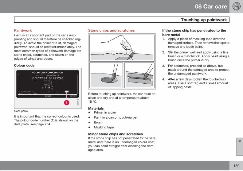
08 Car care
Touching up paintwork
08
189
Paintwork
Paint is an important part of the car's rust-
proofing and should therefore be checked reg-
ularly. To avoid the onset of rust, damaged
paintwork should be rectified immediately. The
most common types of paintwork damage are
stone chips, scratches, and stains on the
edges of wings and doors.
Colour code
G02
0346
Data plate.
It is important that the correct colour is used.
The colour code number (1) is shown on the
data plate, see page 264.
Stone chips and scratches
G02
0345
Before touching up paintwork, the car must be
clean and dry and at a temperature above
15 °C.
Materials
• Primer in a can
• Paint in a can or touch-up pen
• Brush
• Masking tape.
Minor stone chips and scratchesIf the stone chip has not penetrated to the bare
metal and there is an undamaged colour coat,
you can paint straight after cleaning the dam-
aged area.
If the stone chip has penetrated to the
bare metal1. Apply a piece of masking tape over the
damaged surface. Then remove the tape to
remove any loose paint.
2. Stir the primer well and apply using a fine
brush or a matchstick. Apply paint using a
brush once the primer is dry.
3. For scratches, proceed as above, but
mask around the damaged area to protect
the undamaged paintwork.
4. After a few days, polish the touched-up
areas. Use a soft rag and a small amount
of lapping paste.
08 Car care
Rustproofing
08
190
Inspection and maintenance
Your car has already received a thorough and
complete rustproofing at the factory. Parts of
the body are made of galvanised sheet metal.
The underbody is protected by a wear-resis-
tant anti-corrosion compound. A thin, pene-
trating rustproofing fluid was sprayed into the
members, cavities and closed sections.
Maintain the car's rustproofing.
• Keep the car clean. Hose down the under-body. If using a pressure washer, keep thenozzle at least 30 cm from the painted sur-faces.
• Regularly check and touch-up the rust-proofing treatment as necessary.
The car's rustproofing does not normally
require treatment for approximately 12 years.
After this period, it should be treated at three-
year intervals. If the car needs further treat-
ment, please contact an authorised Volvo
workshop.

08 Car care
08
191
G02
0922
192
Volvo service......................................................................................... 194
Self-maintenance.................................................................................. 195
Bonnet and engine compartment......................................................... 196
Diesel.................................................................................................... 198
Oils and fluids....................................................................................... 199
Wiper blades......................................................................................... 203
Battery................................................................................................... 205
Replacing bulbs.................................................................................... 207
Fuses..................................................................................................... 214
09MAINTENANCE AND SERVICE
09 Maintenance and service
Volvo service09
194
Volvo service programme
Before the car left the factory, it was thoroughly
test driven. It was checked again in accord-
ance with Volvo Car Corporation regulations
before it was handed over to you.
To keep your Volvo as safe and reliable as pos-
sible, follow the Volvo service programme
specified in the Service and Warranty Booklet.
Have an authorised Volvo workshop carry out
service and maintenance work. Volvo work-
shops have the personnel, special tools and
service literature to guarantee the highest qual-
ity of service.
IMPORTANT
For the Volvo warranty to apply, check andfollow the instructions in the Service andWarranty Booklet.
Special service measures
Certain service measures which affect the car's
electrical system can only be performed using
electronic equipment specially developed for
your car. For this reason, always contact an
authorised Volvo workshop before beginning
or performing service work that affects the
electrical system.

09 Maintenance and service
Self-maintenance 09
195
Before starting work on the car
BatteryCheck that the battery cables are correctly
connected and tightened.
Never disconnect the battery when the engine
is running (e.g. if replacing the battery).
Never use a quick charger to charge the bat-
tery. The battery cables must be disconnected
when charging the battery.
The battery contains acid that is both corrosive
and toxic. It is therefore important to handle the
battery in an environmentally correct manner.
Let your Volvo dealer assist you.
WARNING
High output from the ignition system. Thevoltage in the ignition system is highly dan-gerous. The ignition must therefore alwaysbe switched off for work in the engine com-partment.
Do not touch the spark plugs or ignition coilswhen the ignition is on or the engine is hot.
Check regularly
Check the following at regular intervals, for
example, when refuelling:
• Coolant – The level must be between theMIN and MAX marks on the expansiontank.
• Engine oil – The level must be between theMIN and MAX marks.
• Power steering fluid – The level must bebetween the MIN and MAX marks.
• Washer fluid – The reservoir should be wellfilled. Use washer antifreeze at tempera-tures around freezing.
• Brake and clutch fluid – The level must bebetween the MIN and MAX marks.
WARNING
Bear in mind that the radiator fan may startautomatically some time after the enginehas been switched off.
Always have the engine cleaned by a work-shop. There is a risk of fire if the engine ishot.
Lifting the car
G02
7001
If the car is lifted with a workshop jack; position
the jack with the front edge on the subframe.
Do not damage the splashguard under the
engine. Ensure that the jack is positioned so
that the car cannot slide off the jack. Always
use axle stands or the like.
If you lift the car using a two pillar workshop lift,
ensure that the front and rear lift arms are fixed
under the lifting points on the door sill. See
previous illustration.
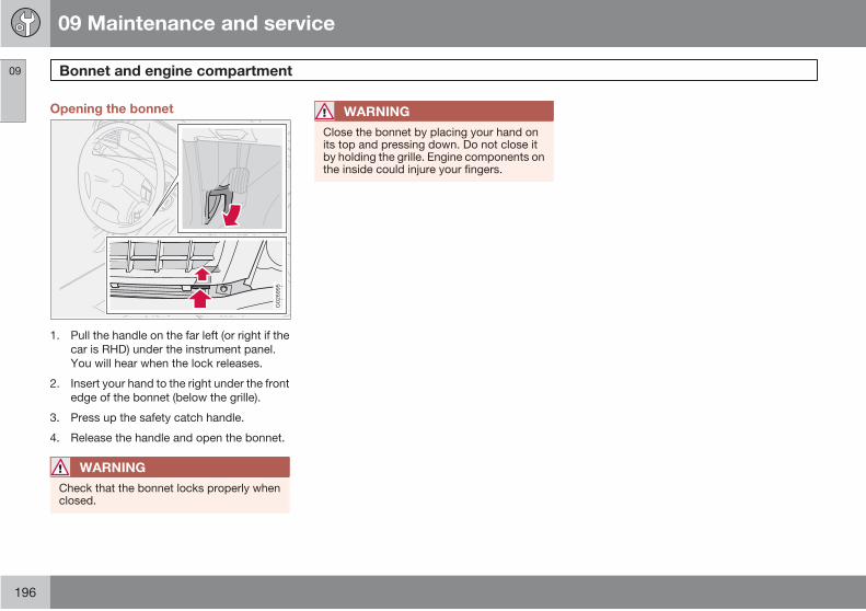
09 Maintenance and service
Bonnet and engine compartment09
196
Opening the bonnet
G02
6995
1. Pull the handle on the far left (or right if the
car is RHD) under the instrument panel.
You will hear when the lock releases.
2. Insert your hand to the right under the front
edge of the bonnet (below the grille).
3. Press up the safety catch handle.
4. Release the handle and open the bonnet.
WARNING
Check that the bonnet locks properly whenclosed.
WARNING
Close the bonnet by placing your hand onits top and pressing down. Do not close itby holding the grille. Engine components onthe inside could injure your fingers.

09 Maintenance and service
Bonnet and engine compartment 09
197
Engine compartment
G02
7074
Clutch and brake fluid reservoir
Relay and fuses
Air filter. (The cover has a different design
depending on engine variant.)
Radiator
Engine oil dipstick
Engine oil filling
Washer fluid reservoir
Power steering fluid reservoir
Expansion tank, cooling system
Chassis data plate
Battery (in cargo area)
09 Maintenance and service
Diesel09
198
Fuel system
Diesel engines are sensitive to contaminants.
Only use diesel fuel from a well-known oil com-
panies. Never use diesel of dubious quality,
see page 273. Special diesel fuel designed for
low temperatures around freezing point is also
available from the major oil companies. This
fuel is less viscous at low temperatures and
reduces the risk of paraffin precipitate.
The risk of condensation in the fuel tank is
reduced if the tank is kept well filled. When
refuelling, check that the area around the fuel
filler pipe is clean. Avoid spilling fuel onto the
paintwork. Wash off any spillage with deter-
gent and water.
IMPORTANT
Only ever use fuel that fulfils the Europeandiesel standard, see page 273.
IMPORTANT
Diesel type fuels which must not be used:special additives, Marine Diesel Fuel, fueloil, RME 1 (Rape Methyl Ester) and vegeta-ble oil. These fuels do not fulfil the require-ments in accordance with Volvo recommen-dations and generate increased wear andengine damage that is not covered by theVolvo warranty.
IMPORTANT
For model year 2006 or later the sulphurcontent must be a maximum of 50 ppm.
Empty tank
No special procedures are required if the tank
runs dry. The fuel system is bled automatically
if the ignition switch is kept in position II for
approx. 60 seconds before the start attempt.
Draining condensation from the fuelfilter
The fuel filter separates condensation from the
fuel. Condensation can disrupt engine opera-
tion.
The fuel filter must be drained at the intervals
specified in the Service and Warranty Booklet
or if you suspect that the car has been filled
with contaminated fuel.
IMPORTANT
Certain special additives remove the waterseparation in the fuel filter.
1 Diesel fuel may contain a certain amount of RME, but further amounts must not be added.
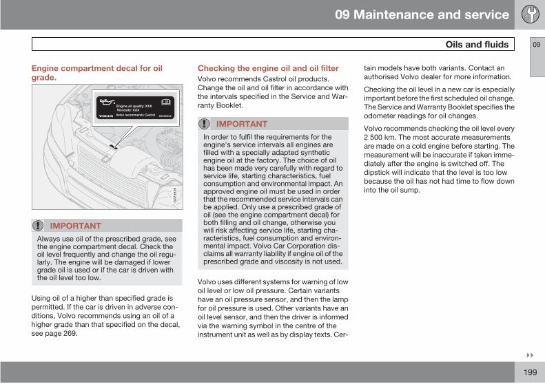
09 Maintenance and service
Oils and fluids 09
199
Engine compartment decal for oilgrade.
G02
1626
IMPORTANT
Always use oil of the prescribed grade, seethe engine compartment decal. Check theoil level frequently and change the oil regu-larly. The engine will be damaged if lowergrade oil is used or if the car is driven withthe oil level too low.
Using oil of a higher than specified grade is
permitted. If the car is driven in adverse con-
ditions, Volvo recommends using an oil of a
higher grade than that specified on the decal,
see page 269.
Checking the engine oil and oil filter
Volvo recommends Castrol oil products.
Change the oil and oil filter in accordance with
the intervals specified in the Service and War-
ranty Booklet.
IMPORTANT
In order to fulfil the requirements for theengine's service intervals all engines arefilled with a specially adapted syntheticengine oil at the factory. The choice of oilhas been made very carefully with regard toservice life, starting characteristics, fuelconsumption and environmental impact. Anapproved engine oil must be used in orderthat the recommended service intervals canbe applied. Only use a prescribed grade ofoil (see the engine compartment decal) forboth filling and oil change, otherwise youwill risk affecting service life, starting cha-racteristics, fuel consumption and environ-mental impact. Volvo Car Corporation dis-claims all warranty liability if engine oil of theprescribed grade and viscosity is not used.
Volvo uses different systems for warning of low
oil level or low oil pressure. Certain variants
have an oil pressure sensor, and then the lamp
for oil pressure is used. Other variants have an
oil level sensor, and then the driver is informed
via the warning symbol in the centre of the
instrument unit as well as by display texts. Cer-
tain models have both variants. Contact an
authorised Volvo dealer for more information.
Checking the oil level in a new car is especially
important before the first scheduled oil change.
The Service and Warranty Booklet specifies the
odometer readings for oil changes.
Volvo recommends checking the oil level every
2 500 km. The most accurate measurements
are made on a cold engine before starting. The
measurement will be inaccurate if taken imme-
diately after the engine is switched off. The
dipstick will indicate that the level is too low
because the oil has not had time to flow down
into the oil sump.
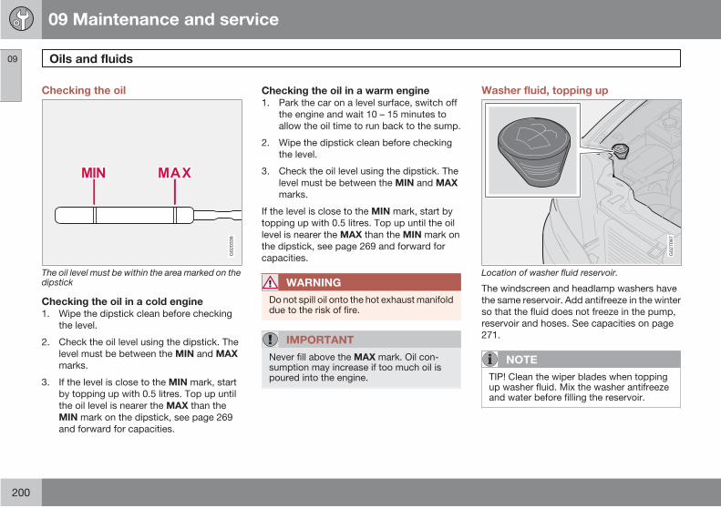
09 Maintenance and service
Oils and fluids09
200
Checking the oil
G02
0336
The oil level must be within the area marked on thedipstick
Checking the oil in a cold engine1. Wipe the dipstick clean before checking
the level.
2. Check the oil level using the dipstick. The
level must be between the MIN and MAX
marks.
3. If the level is close to the MIN mark, start
by topping up with 0.5 litres. Top up until
the oil level is nearer the MAX than the
MIN mark on the dipstick, see page 269
and forward for capacities.
Checking the oil in a warm engine1. Park the car on a level surface, switch off
the engine and wait 10 – 15 minutes to
allow the oil time to run back to the sump.
2. Wipe the dipstick clean before checking
the level.
3. Check the oil level using the dipstick. The
level must be between the MIN and MAX
marks.
If the level is close to the MIN mark, start by
topping up with 0.5 litres. Top up until the oil
level is nearer the MAX than the MIN mark on
the dipstick, see page 269 and forward for
capacities.
WARNING
Do not spill oil onto the hot exhaust manifolddue to the risk of fire.
IMPORTANT
Never fill above the MAX mark. Oil con-sumption may increase if too much oil ispoured into the engine.
Washer fluid, topping up
G02
7097
Location of washer fluid reservoir.
The windscreen and headlamp washers have
the same reservoir. Add antifreeze in the winter
so that the fluid does not freeze in the pump,
reservoir and hoses. See capacities on page
271.
NOTE
TIP! Clean the wiper blades when toppingup washer fluid. Mix the washer antifreezeand water before filling the reservoir.
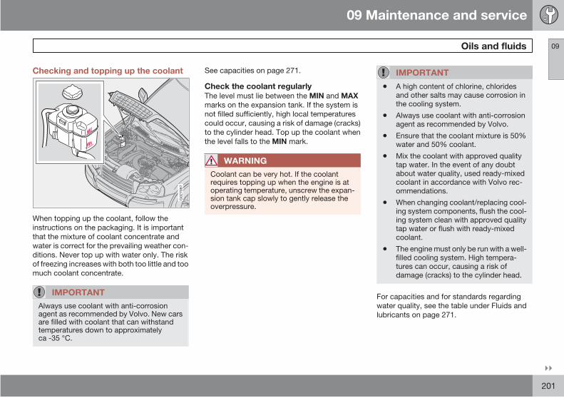
09 Maintenance and service
Oils and fluids 09
201
Checking and topping up the coolant
G02
7087
When topping up the coolant, follow the
instructions on the packaging. It is important
that the mixture of coolant concentrate and
water is correct for the prevailing weather con-
ditions. Never top up with water only. The risk
of freezing increases with both too little and too
much coolant concentrate.
IMPORTANT
Always use coolant with anti-corrosionagent as recommended by Volvo. New carsare filled with coolant that can withstandtemperatures down to approximatelyca -35 °C.
See capacities on page 271.
Check the coolant regularlyThe level must lie between the MIN and MAX
marks on the expansion tank. If the system is
not filled sufficiently, high local temperatures
could occur, causing a risk of damage (cracks)
to the cylinder head. Top up the coolant when
the level falls to the MIN mark.
WARNING
Coolant can be very hot. If the coolantrequires topping up when the engine is atoperating temperature, unscrew the expan-sion tank cap slowly to gently release theoverpressure.
IMPORTANT
• A high content of chlorine, chloridesand other salts may cause corrosion inthe cooling system.
• Always use coolant with anti-corrosionagent as recommended by Volvo.
• Ensure that the coolant mixture is 50%water and 50% coolant.
• Mix the coolant with approved qualitytap water. In the event of any doubtabout water quality, used ready-mixedcoolant in accordance with Volvo rec-ommendations.
• When changing coolant/replacing cool-ing system components, flush the cool-ing system clean with approved qualitytap water or flush with ready-mixedcoolant.
• The engine must only be run with a well-filled cooling system. High tempera-tures can occur, causing a risk ofdamage (cracks) to the cylinder head.
For capacities and for standards regarding
water quality, see the table under Fluids and
lubricants on page 271.

09 Maintenance and service
Oils and fluids09
202
Checking and topping up the brake andclutch fluid
G00
0000
Brake and clutch fluid have a common reser-
voir 1. The fluid level must be between the
MIN and MAX marks. Check the level regularly.
Change the brake fluid every other year or at
every other regular service.
See the capacities and recommended fluid
grade on page 271.
The fluid should be changed annually on cars
driven in conditions requiring hard, frequent
braking, such as driving in mountains or tropi-
cal climates with high humidity.
WARNING
If the brake fluid is under the MIN level in thebrake fluid reservoir, do not drive furtherbefore topping up the brake fluid.
The reason for the loss of brake fluid mustbe investigated.
Checking and topping up the powersteering fluid
FULL ADD
G02
6991
NOTE
Check the level frequently.
Check the level frequently. The fluid does not
require changing. The level must lie between
the ADD and FULL marks. See the capacities
and recommended grade on page 271.
NOTE
If a fault should arise in the power steeringsystem or if the car is without power andmust be towed, it can still be steered. How-ever, the steering will be much heavier thannormal and it will require more effort to turnthe steering wheel.
1 Location dependent on whether car is left or right-hand drive.

09 Maintenance and service
Wiper blades 09
203
Wiper blades
CleaningFor cleaning wiper blades and windscreen, see
page 186.
IMPORTANT
Check the wiper blades regularly.Neglected maintenance shortens the serv-ice life of the wiper blades.
Replacing the wiper blades, windscreen NOTE
The wiper blades are different lengths. Theblade on the driver's side is longer than onthe other side.
1. Fold out the wiper arm and grasp the wiper
blade.
2. Press in the ribbed spring catch on the
wiper blade while lifting it off at the arm
extension.
3. Fit the new blade in reverse order and
check that it is properly secured.
Changing the rear window wiper blade
G02
6959
1. Fold out the wiper arm.

09 Maintenance and service
Wiper blades09
204
2. Remove the wiper blade by moving it up/
out (see illustration) towards the tailgate.
3. Press the new wiper blade into position.
4. Check that the blade is firmly installed.

09 Maintenance and service
Battery 09
205
Battery care
The service life and function of the battery is
influenced by factors such as the number of
starts, discharging, driving style, driving con-
ditions and climatic conditions.
NOTE
An expended battery must be recycled in anenvironmentally responsible manner as itcontains lead.
WARNING
Batteries can generate oxyhydrogen gas,which is highly explosive. One spark, whichcan be generated if you connect the jumpleads incorrectly, is sufficient to make thebattery explode. The battery contains sul-phuric acid, which can cause serious burns.If the acid comes into contact with eyes,skin or clothing, flush with large quantitiesof water. If acid splashes into the eyes, seekmedical attention immediately.
NOTE
The life of the battery is shortened if itbecomes discharged repeatedly.
Symbols on the battery
Further information in the
owner's manual.
Store the battery out of the
reach of children.
The battery contains corro-
sive acid.
Avoid sparks and naked
flames.
Risk of explosion.
Use protective goggles.

09 Maintenance and service
Battery09
206
Changing the battery
Removing the battery
G02
7075
1. Switch off the ignition and remove the key
2. Unscrew the bracket and cover over the
battery
3. Wait at least 5 minutes before touching any
electrical terminals. (This allows time for
the information in your car's electrical sys-
tem to be stored in the control modules.)
4. Disconnect the negative lead first
5. Then disconnect the positive lead and the
evacuation hose for the oxyhydrogen gas
Fitting the battery
DRAIN PIPE
xxxx xxxxx xx xxxxxDISCONNECT
REMOVAL OF BATTERYO CABLE FIRST
xxxx xxxxx xxxxxxxxx xx
+-
WARNING
xxxx xxxxx xx xxxxx
G02
7076
1. Set the battery in place
2. Connect the positive lead
3. Connect the negative lead
4. Make sure the evacuation hose is correctly
connected to both the battery and the out-
let in the bodywork.
5. Refit the cover and bracket
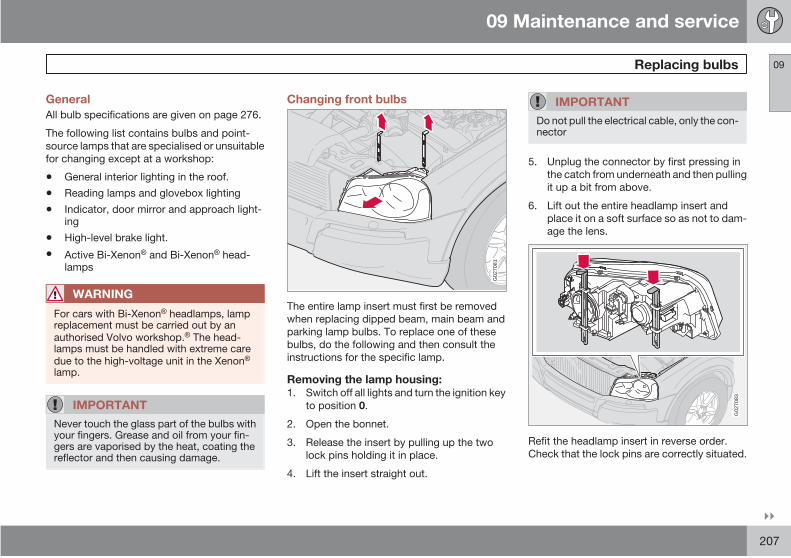
09 Maintenance and service
Replacing bulbs 09
207
General
All bulb specifications are given on page 276.
The following list contains bulbs and point-
source lamps that are specialised or unsuitable
for changing except at a workshop:
• General interior lighting in the roof.
• Reading lamps and glovebox lighting
• Indicator, door mirror and approach light-ing
• High-level brake light.
• Active Bi-Xenon and Bi-Xenon head-lamps
WARNING
For cars with Bi-Xenon headlamps, lampreplacement must be carried out by anauthorised Volvo workshop. The head-lamps must be handled with extreme caredue to the high-voltage unit in the Xenonlamp.
IMPORTANT
Never touch the glass part of the bulbs withyour fingers. Grease and oil from your fin-gers are vaporised by the heat, coating thereflector and then causing damage.
Changing front bulbs
G02
7081
The entire lamp insert must first be removed
when replacing dipped beam, main beam and
parking lamp bulbs. To replace one of these
bulbs, do the following and then consult the
instructions for the specific lamp.
Removing the lamp housing:1. Switch off all lights and turn the ignition key
to position 0.
2. Open the bonnet.
3. Release the insert by pulling up the two
lock pins holding it in place.
4. Lift the insert straight out.
IMPORTANT
Do not pull the electrical cable, only the con-nector
5. Unplug the connector by first pressing in
the catch from underneath and then pulling
it up a bit from above.
6. Lift out the entire headlamp insert and
place it on a soft surface so as not to dam-
age the lens.
G02
7083
Refit the headlamp insert in reverse order.
Check that the lock pins are correctly situated.
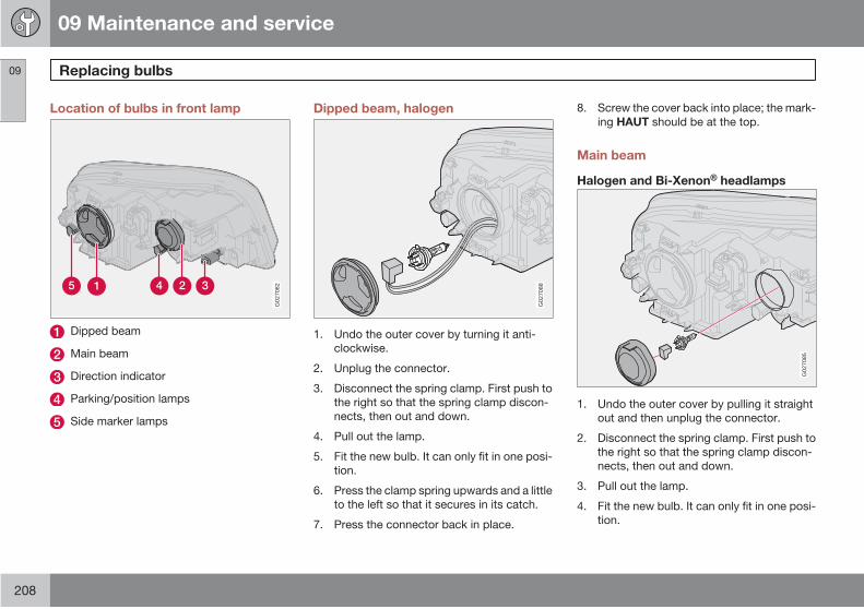
09 Maintenance and service
Replacing bulbs09
208
Location of bulbs in front lamp
G02
7082
Dipped beam
Main beam
Direction indicator
Parking/position lamps
Side marker lamps
Dipped beam, halogen
G02
7088
1. Undo the outer cover by turning it anti-
clockwise.
2. Unplug the connector.
3. Disconnect the spring clamp. First push to
the right so that the spring clamp discon-
nects, then out and down.
4. Pull out the lamp.
5. Fit the new bulb. It can only fit in one posi-
tion.
6. Press the clamp spring upwards and a little
to the left so that it secures in its catch.
7. Press the connector back in place.
8. Screw the cover back into place; the mark-
ing HAUT should be at the top.
Main beam
Halogen and Bi-Xenon headlamps
G02
7085
1. Undo the outer cover by pulling it straight
out and then unplug the connector.
2. Disconnect the spring clamp. First push to
the right so that the spring clamp discon-
nects, then out and down.
3. Pull out the lamp.
4. Fit the new bulb. It can only fit in one posi-
tion.
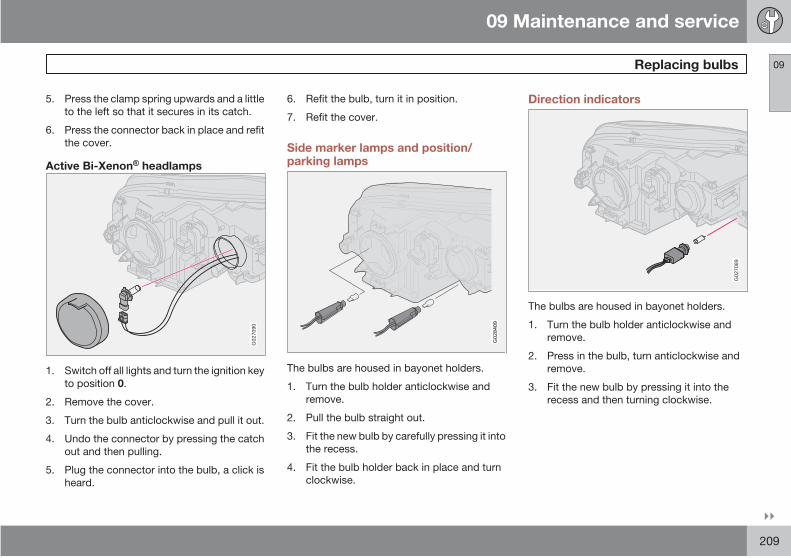
09 Maintenance and service
Replacing bulbs 09
209
5. Press the clamp spring upwards and a little
to the left so that it secures in its catch.
6. Press the connector back in place and refit
the cover.
Active Bi-Xenon headlamps
G02
7090
1. Switch off all lights and turn the ignition key
to position 0.
2. Remove the cover.
3. Turn the bulb anticlockwise and pull it out.
4. Undo the connector by pressing the catch
out and then pulling.
5. Plug the connector into the bulb, a click is
heard.
6. Refit the bulb, turn it in position.
7. Refit the cover.
Side marker lamps and position/parking lamps
G02
8409
The bulbs are housed in bayonet holders.
1. Turn the bulb holder anticlockwise and
remove.
2. Pull the bulb straight out.
3. Fit the new bulb by carefully pressing it into
the recess.
4. Fit the bulb holder back in place and turn
clockwise.
Direction indicators
G02
7089
The bulbs are housed in bayonet holders.
1. Turn the bulb holder anticlockwise and
remove.
2. Press in the bulb, turn anticlockwise and
remove.
3. Fit the new bulb by pressing it into the
recess and then turning clockwise.

09 Maintenance and service
Replacing bulbs09
210
Front fog lamps
G02
7078
1. Switch off all lights and turn the ignition key
to position 0.
2. Turn the bulb holder slightly anticlockwise.
3. Remove the lamp.
4. Fit the new bulb. The profile of the bulb
holder matches the one on the foot of the
lamp.
5. Refit the bulb holder by turning slightly
clockwise. The TOP mark on the bulb
holder must be upward.
Bulbs in rear lamp cluster
G02
7094
Position lamps
Direction indicators
Reversing lamp
Position lamps
Brake light
NOTE
If the error message BULB FAILURE/CHECK STOP LAMP remains after a faultybulb has been replaced then consult anauthorised Volvo workshop.
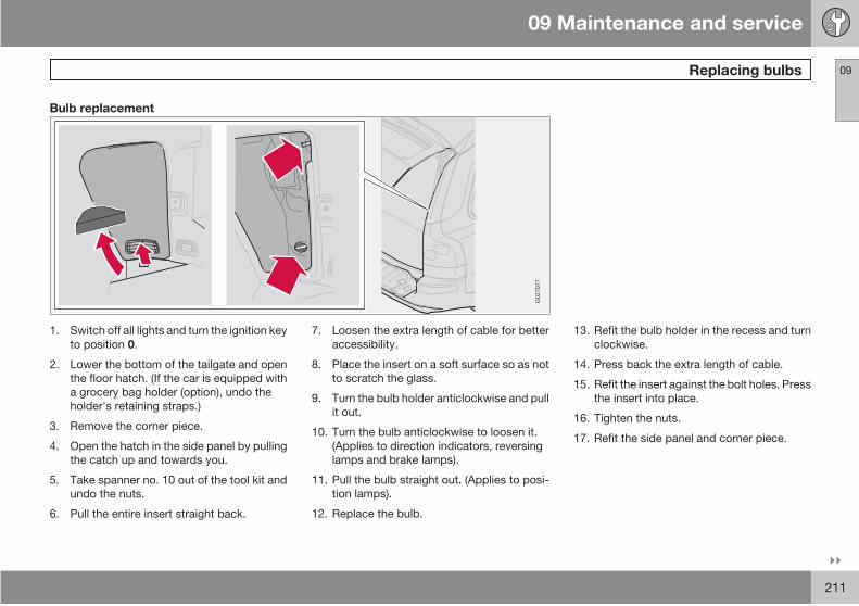
09 Maintenance and service
Replacing bulbs 09
211
Bulb replacement
G02
7077
1. Switch off all lights and turn the ignition key
to position 0.
2. Lower the bottom of the tailgate and open
the floor hatch. (If the car is equipped with
a grocery bag holder (option), undo the
holder's retaining straps.)
3. Remove the corner piece.
4. Open the hatch in the side panel by pulling
the catch up and towards you.
5. Take spanner no. 10 out of the tool kit and
undo the nuts.
6. Pull the entire insert straight back.
7. Loosen the extra length of cable for better
accessibility.
8. Place the insert on a soft surface so as not
to scratch the glass.
9. Turn the bulb holder anticlockwise and pull
it out.
10. Turn the bulb anticlockwise to loosen it.
(Applies to direction indicators, reversing
lamps and brake lamps).
11. Pull the bulb straight out. (Applies to posi-
tion lamps).
12. Replace the bulb.
13. Refit the bulb holder in the recess and turn
clockwise.
14. Press back the extra length of cable.
15. Refit the insert against the bolt holes. Press
the insert into place.
16. Tighten the nuts.
17. Refit the side panel and corner piece.
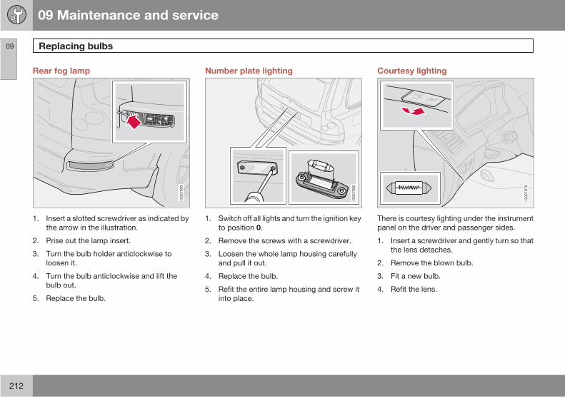
09 Maintenance and service
Replacing bulbs09
212
Rear fog lamp
G02
7093
1. Insert a slotted screwdriver as indicated by
the arrow in the illustration.
2. Prise out the lamp insert.
3. Turn the bulb holder anticlockwise to
loosen it.
4. Turn the bulb anticlockwise and lift the
bulb out.
5. Replace the bulb.
Number plate lighting
G02
7092
1. Switch off all lights and turn the ignition key
to position 0.
2. Remove the screws with a screwdriver.
3. Loosen the whole lamp housing carefully
and pull it out.
4. Replace the bulb.
5. Refit the entire lamp housing and screw it
into place.
Courtesy lighting
G02
7079
There is courtesy lighting under the instrument
panel on the driver and passenger sides.
1. Insert a screwdriver and gently turn so that
the lens detaches.
2. Remove the blown bulb.
3. Fit a new bulb.
4. Refit the lens.
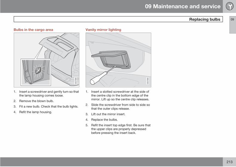
09 Maintenance and service
Replacing bulbs 09
213
Bulbs in the cargo area
G02
7084
1. Insert a screwdriver and gently turn so that
the lamp housing comes loose.
2. Remove the blown bulb.
3. Fit a new bulb. Check that the bulb lights.
4. Refit the lamp housing.
Vanity mirror lighting
G02
7080
1. Insert a slotted screwdriver at the side of
the centre clip in the bottom edge of the
mirror. Lift up so the centre clip releases.
2. Slide the screwdriver from side to side so
that the outer clips release.
3. Lift out the mirror insert.
4. Replace the bulbs.
5. Refit the insert top edge first. Be sure that
the upper clips are properly depressed
before pressing the insert back.

09 Maintenance and service
Fuses09
214
General
G03
2337
Cable routing may vary slightly due to engine variant. However, the components listed are in the same positions.
All electrical functions and components are
protected with a number of fuses to protect
your car's electrical system from damage by
short-circuits or overloads.
The fuses are in five different locations in the
car:
Relay/fuse box in the engine compartment.
Fuse box in the passenger compartment
within the sound barrier on the driver's
side.
Fuse box in the passenger compartment at
dashboard end on driver's side.
Fuse box in cargo area.
Fuse box in cargo area - Executive*
If an electrical component or function does not
work, this may be because the component's
fuse was temporarily overloaded and blew.
1. Look in the fuse diagram to locate the fuse.
2. Pull out the fuse and check from the side
to see whether the curved wire has blown.
3. If this is the case, replace it with a new fuse
of the same colour and amperage.
WARNING
Never use a foreign object, or a fuse with anamperage higher than that specified whenreplacing a fuse. This could cause signifi-cant damage to the electrical system andpossibly lead to fire.
There are a number of spare fuses in the cover
on the end face of the dashboard. There are
also pliers which facilitate the removal and fit-
ting of fuses.
09 Maintenance and service
Fuses 09
215
If the same fuse blows repeatedly, there is a
fault in the component. Contact an authorised
Volvo workshop to have it checked.
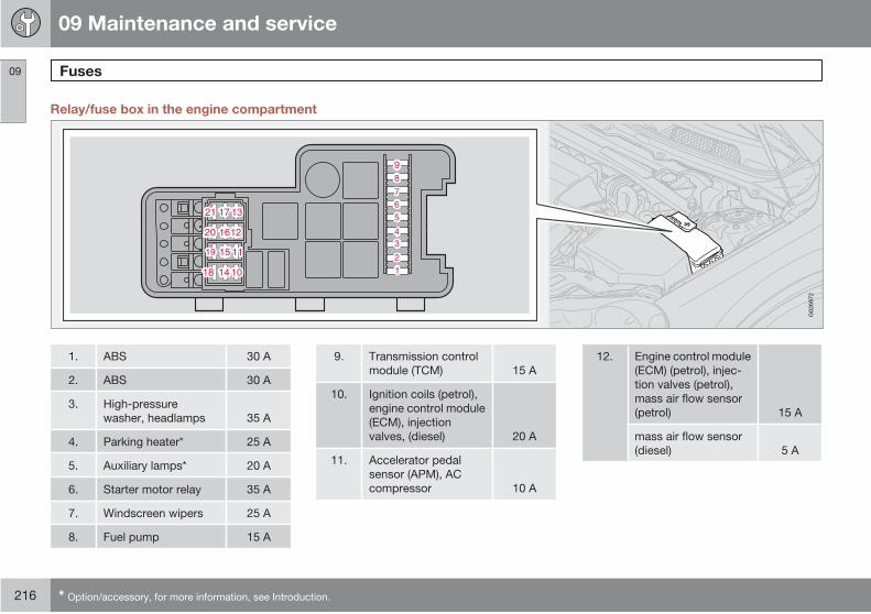
09 Maintenance and service
Fuses09
216 * Option/accessory, for more information, see Introduction.
Relay/fuse box in the engine compartment
G02
6972
1. ABS 30 A
2. ABS 30 A
3. High-pressure
washer, headlamps 35 A
4. Parking heater* 25 A
5. Auxiliary lamps* 20 A
6. Starter motor relay 35 A
7. Windscreen wipers 25 A
8. Fuel pump 15 A
9. Transmission control
module (TCM) 15 A
10. Ignition coils (petrol),
engine control module
(ECM), injection
valves, (diesel) 20 A
11. Accelerator pedal
sensor (APM), AC
compressor 10 A
12. Engine control module
(ECM) (petrol), injec-
tion valves (petrol),
mass air flow sensor
(petrol) 15 A
mass air flow sensor
(diesel) 5 A
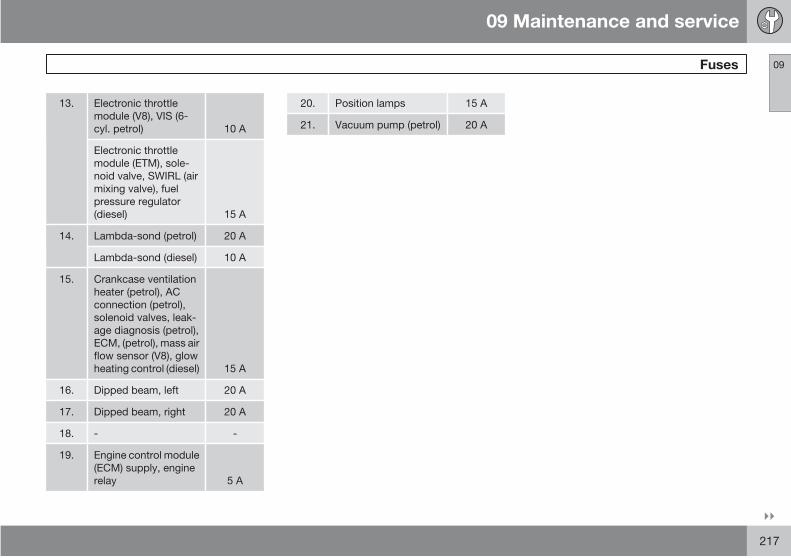
09 Maintenance and service
Fuses 09
217
13. Electronic throttle
module (V8), VIS (6-
cyl. petrol) 10 A
Electronic throttle
module (ETM), sole-
noid valve, SWIRL (air
mixing valve), fuel
pressure regulator
(diesel) 15 A
14. Lambda-sond (petrol) 20 A
Lambda-sond (diesel) 10 A
15. Crankcase ventilation
heater (petrol), AC
connection (petrol),
solenoid valves, leak-
age diagnosis (petrol),
ECM, (petrol), mass air
flow sensor (V8), glow
heating control (diesel) 15 A
16. Dipped beam, left 20 A
17. Dipped beam, right 20 A
18. - -
19. Engine control module
(ECM) supply, engine
relay 5 A
20. Position lamps 15 A
21. Vacuum pump (petrol) 20 A
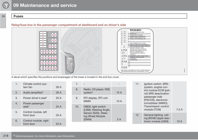
09 Maintenance and service
Fuses09
218 * Option/accessory, for more information, see Introduction.
Relay/fuse box in the passenger compartment at dashboard end on driver's side
G03
2316
A decal which specifies the positions and amperages of the fuses is located in the end box cover.
1. Climate control sys-
tem fan 30 A
2. Audio (amplifier)* 30 A
3. Power driver's seat* 25 A
4. Power passenger
seat* 25 A
5. Control module, left
front door 25 A
6. Control module, right
front door 25 A
7. - -
8. Radio, CD player, RSE
system* 15 A
9. RTI display, RTI unit
MMM 10 A
10. OBDII, light switch
(LSM), Steering Angle
Sensor (SAS), Steer-
ing Wheel Module
(SWM) 5 A
11. Ignition switch, SRS-
system, engine con-
trol module ECM (pet-
rol) SRS deactivation
passenger side
(PACOS), electronic
immobiliser (IMMO),
Transmission control
module (TCM) 7.5 A
12. General lighting, ceil-
ing (RCM) Upper elec-
tronic module (UEM) 10 A
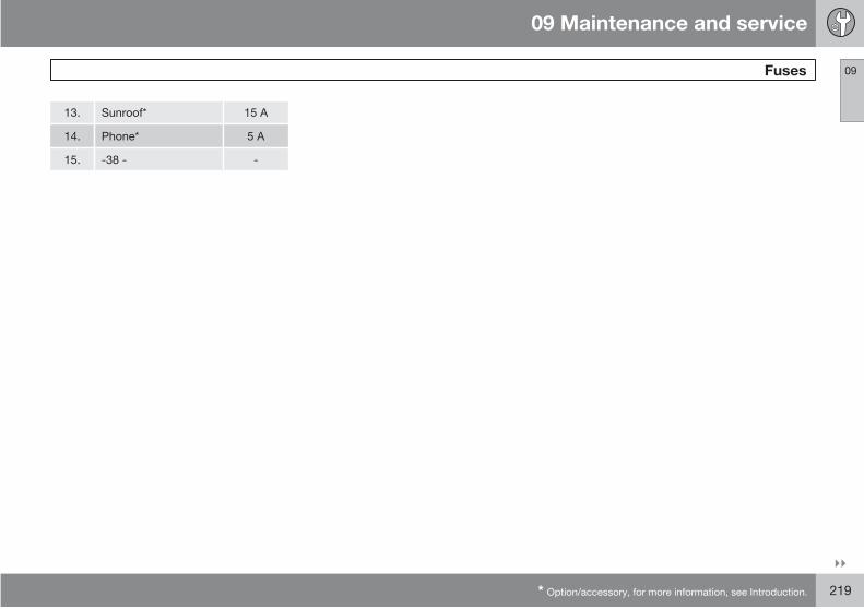
09 Maintenance and service
Fuses 09
* Option/accessory, for more information, see Introduction. 219
13. Sunroof* 15 A
14. Phone* 5 A
15. -38 - -
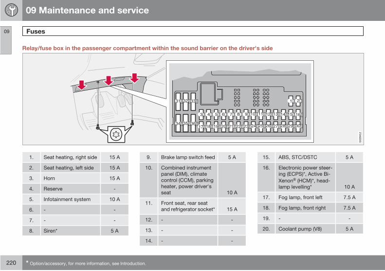
09 Maintenance and service
Fuses09
220 * Option/accessory, for more information, see Introduction.
Relay/fuse box in the passenger compartment within the sound barrier on the driver's side
G02
8412
1. Seat heating, right side 15 A
2. Seat heating, left side 15 A
3. Horn 15 A
4. Reserve -
5. Infotainment system 10 A
6. - -
7. - -
8. Siren* 5 A
9. Brake lamp switch feed 5 A
10. Combined instrument
panel (DIM), climate
control (CCM), parking
heater, power driver's
seat 10 A
11. Front seat, rear seat
and refrigerator socket* 15 A
12. - -
13. - -
14. - -
15. ABS, STC/DSTC 5 A
16. Electronic power steer-
ing (ECPS)*, Active Bi-
Xenon (HCM)*, head-
lamp levelling* 10 A
17. Fog lamp, front left 7.5 A
18. Fog lamp, front right 7.5 A
19. - -
20. Coolant pump (V8) 5 A
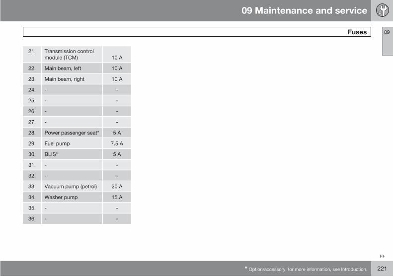
09 Maintenance and service
Fuses 09
* Option/accessory, for more information, see Introduction. 221
21. Transmission control
module (TCM) 10 A
22. Main beam, left 10 A
23. Main beam, right 10 A
24. - -
25. - -
26. - -
27. - -
28. Power passenger seat* 5 A
29. Fuel pump 7.5 A
30. BLIS* 5 A
31. - -
32. - -
33. Vacuum pump (petrol) 20 A
34. Washer pump 15 A
35. - -
36. - -

09 Maintenance and service
Fuses09
222 * Option/accessory, for more information, see Introduction.
Fuses in the cargo area
G03
2342
1. Reversing lamp 10 A
2. Position lamps, fog
lamps, cargo area light-
ing, number plate light-
ing, lamps in brake
lighting 20 A
3. Accessories (AEM)* 15 A
4. Reserve -
5. REM electronics 10 A
6. RSE system* 7.5 A
7. Towing bracket wiring*
(30-feed) 15 A
8. Cargo area socket 15 A
9. Rear right door: Power
window, power window
lock 20 A
10. Rear left door: Power
window, power window
lock 20 A
11. - -
12. - -
13. Diesel filter heater 15 A
14. Subwoofer, rear air
conditioning (A/C)* 15 A
15. - -
16. - -
17. Infotainment system
accessories* 5 A
18. - -
19. Rear wiper 15 A
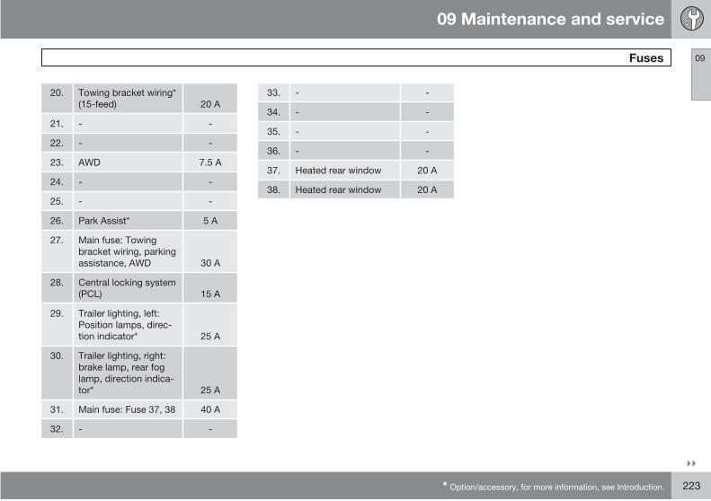
09 Maintenance and service
Fuses 09
* Option/accessory, for more information, see Introduction. 223
20. Towing bracket wiring*
(15-feed) 20 A
21. - -
22. - -
23. AWD 7.5 A
24. - -
25. - -
26. Park Assist* 5 A
27. Main fuse: Towing
bracket wiring, parking
assistance, AWD 30 A
28. Central locking system
(PCL) 15 A
29. Trailer lighting, left:
Position lamps, direc-
tion indicator* 25 A
30. Trailer lighting, right:
brake lamp, rear fog
lamp, direction indica-
tor* 25 A
31. Main fuse: Fuse 37, 38 40 A
32. - -
33. - -
34. - -
35. - -
36. - -
37. Heated rear window 20 A
38. Heated rear window 20 A

09 Maintenance and service
Fuses09
224 * Option/accessory, for more information, see Introduction.
Fuses in the cargo area - Executive*
G03
1532
The fuse box is located behind the cover panel
on the left-hand side.
1. Relay, seat heating,
rear seat, Relay, mas-
sage seat, front 5 A
2. Seat heating, rear seat,
left 15 A
3. Seat heating, rear seat,
right 15 A
4. Ventilated seat front,
Massage seat front 5 A
5. - -
6. - -

09 Maintenance and service
09
225

G02
0924
226 * Option/accessory, for more information, see Introduction.
General.................................................................................................. 228
Control panels, audio............................................................................ 229
Audio system functions......................................................................... 233
Radio functions..................................................................................... 236
CD functions......................................................................................... 242
Menu structure – audio system............................................................. 244
Phone functions*................................................................................... 245
RSE - Rear Seat Entertainment system - Dual Screen* ....................... 252
Menu structure – phone........................................................................ 257

10INFOTAINMENT SYSTEM

10 Infotainment system
General
10
228 * Option/accessory, for more information, see Introduction.
Infotainment system
Infotainment is a system that integrates the
audio system and phone functions.
You can easily and conveniently use your Info-
tainment system by means of the joint control
panel or the steering wheel keypad.
XC90 can be equipped with Dolby Surround
Pro Logic II 1. This offers an optimal sound
experience very close to being there with a
broad, natural sound profile.
The system also allows your passengers to use
headphones* with separate audio sources.
Dolby Surround Pro Logic II1
Dolby Surround Pro Logic II distributes the two
stereo audio channels to left, centre, right and
rear speakers. This provides a more realistic
sound quality than that provided by standard
two-channel stereo.
Dolby Surround Pro Logic II and the
Dolby icon are trademarks of Dolby
Laboratories Licensing Corporation.
Dolby Surround Pro Logic II System
is manufactured under license from Dolby
Laboratories Licensing Corporation.
1 Applies to Premium Sound.

10 Infotainment system
Control panels, audio
10
* Option/accessory, for more information, see Introduction. 229
Audio controls
G02
7111
POWER - Audio On/Off
VOLUME - Volume (knob control)
CD – shortcuts
AM/FM-shortcut between FM1, FM2 and
AM
Display
ENTER – select in the menu, activate a
selection or activate the phone from
standby mode
PHONE - Phone On/Off/Standby
MY KEY – programmable shortcut key for
your favourite function
SELECTOR – select audio source
SOUND – audio settings
EXIT/CLEAR – scroll back in the menu,
cancel a selection, put the phone in
standby mode, or erase the previous char-
acter when entering text and numbers
SIM card holder
Menu selection buttons
CD and CD changer eject*
CD player and CD changer*
Station setting buttons/selecting CD
changer position* (1-6), number and char-
acter buttons for the phone and menu
shortcuts
IR* - receiver for remote controls
Seek/change tracks/stations or scroll for-
ward and back when entering text and dig-
its

10 Infotainment system
Control panels, audio
10
230 * Option/accessory, for more information, see Introduction.
Steering wheel keypad
Audio – Phone*
G02
7004
The four buttons at the bottom of the steering
wheel keypad control both the radio and the
phone. The function of the respective button
depends on which system is active. The steer-
ing wheel keypad can be used to adjust vol-
ume, switch between preset stations and
change CD tracks.
Menus
G02
7112
Some infotainment system functions are con-
trolled via a menu system. The current menu
level is shown at the top right of the display.
Menu options are shown in the middle of the
display.
• MENU leads to the menu system. Up/
down with the buttons scrolls between
menu options.
• ENTER selects or activates/deactivates amenu option.
• EXIT leads back one step in the menustructure. A long press on EXIT will exit themenu system.
ShortcutsMenu options are numbered and can also be
selected directly with the keypad 1 - 6.
My own shortcut button – MY KEY
Use MY KEY to store a favourite function in the
menu, e.g. TP.
Select the function in the menu to be
stored by holding MY KEY depressed for
more than two seconds.
When MY KEY STORED is shown in the dis-
play, the function has been stored.
Activate the function with a short press on
MY KEY.

10 Infotainment system
Control panels, audio
10
* Option/accessory, for more information, see Introduction. 231
Control panel with headphones socket
G02
6982
Headphones with an impedance of
16 – 32 ohm and sensitivity of 102 dB or higher
are recommended for best sound reproduc-
tion.
Activating/deactivatingThe control panel is activated with SEL when
the audio system is active. Deactivation is
automatic when the audio system is deacti-
vated or with a long press on SEL.
Scroll/search forward and backward
A short press on / scrolls
between CD tracks or preset radio stations.
Long presses are used to fast-wind CD tracks
or to search for radio stations automatically.
LimitationsThe audio source (FM, AM, CD etc.) played
back in the speakers cannot be controlled from
the rear control panel.
RDS messages may not appear if the radio is
playing back in the headphones while another
audio source is playing back in the speakers.
Remote control*
G02
7003
MEMORY – stores searched radio sta-
tions. To store a station:
– Press the MEMORY button
– Select Preset using PRESET/DISC
– Confirm your selection using the Memory
button
VOL – Volume
Seek/change tracks forward or back
SOURCE – switch audio source
PRESET/DISC – select CD changer posi-
tion or preset radio station
AUTO – find and store the strongest sta-
tions
Function not available
Function not available
POWER - Audio On/Off
AM FM
#
72
6468
8076
E
TUV
JKL
ABC
POWER
21
PQRS
GHI
7
4
* 0
8
5
CD MULOV
WXYZ
MNO
DEF
6
3
9
72
64 8068 76
ENTER
SOSE
G02
6984
10 Infotainment system
Control panels, audio
10
232
Direct the remote control towards the IR
receiver (see illustration) that is located in
the dashboard.
NOTE
The remote control contains AAA batteries(R03). If the remote control does not work,first try replacing the batteries.

10 Infotainment system
Audio system functions
10
* Option/accessory, for more information, see Introduction. 233
On/Off switch – Audio
G02
7115
Press the POWER button to switch the
audio system on or off.
If the audio system is active when the ignition
is switched off, it will reactivate automatically
when the car is restarted.
Volume control
Turn the knob clockwise or anticlockwise to
raise or lower the volume respectively. The vol-
ume control is electronic and has no end posi-
tion. Volume can also be raised + or lowered
– using the steering wheel keypad.
Selecting the audio source
Press the AM/FM button repeatedly to tog-
gle between FM1, FM2 and AM. CD acti-
vates the CD player/changer.
Turn SELECTOR to toggle between the
external AUX audio source and the internal
FM1, FM2, AM, CD and CD changer audio
sources*.
AUX
The AUX input can be used for connecting an
MP3 player for example.
NOTE
The audio quality may be impaired if theplayer is charged while the audio system isin AUX mode. In which case, avoid chargingthe player.
Sometimes the external AUX audio source can
be heard at a different volume to the internal
audio sources. If the audio volume of the exter-
nal audio source is too high then the sound
quality can be impaired. Prevent this by adjust-
ing the input volume of the external audio
source:
1. Select AUX VOLUME in the menu and
press ENTER.
2. Control the volume with SELECTOR or up/
down with the buttons . Finish with
ENTER.
NOTE
Does not work for the steering wheel key-pad.
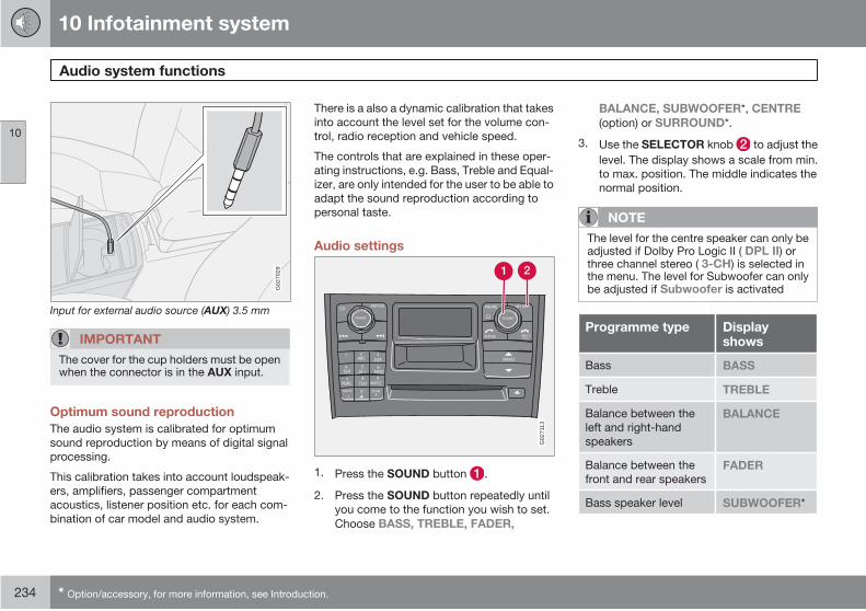
10 Infotainment system
Audio system functions
10
234 * Option/accessory, for more information, see Introduction.
G02
7029
Input for external audio source (AUX) 3.5 mm
IMPORTANT
The cover for the cup holders must be openwhen the connector is in the AUX input.
Optimum sound reproduction
The audio system is calibrated for optimum
sound reproduction by means of digital signal
processing.
This calibration takes into account loudspeak-
ers, amplifiers, passenger compartment
acoustics, listener position etc. for each com-
bination of car model and audio system.
There is a also a dynamic calibration that takes
into account the level set for the volume con-
trol, radio reception and vehicle speed.
The controls that are explained in these oper-
ating instructions, e.g. Bass, Treble and Equal-
izer, are only intended for the user to be able to
adapt the sound reproduction according to
personal taste.
Audio settings
G02
7113
1. Press the SOUND button .
2. Press the SOUND button repeatedly until
you come to the function you wish to set.
Choose BASS, TREBLE, FADER,
BALANCE, SUBWOOFER*, CENTRE
(option) or SURROUND*.
3. Use the SELECTOR knob to adjust the
level. The display shows a scale from min.
to max. position. The middle indicates the
normal position.
NOTE
The level for the centre speaker can only beadjusted if Dolby Pro Logic II ( DPL II) orthree channel stereo ( 3-CH) is selected inthe menu. The level for Subwoofer can onlybe adjusted if Subwoofer is activated
Programme type Displayshows
Bass BASS
Treble TREBLE
Balance between the
left and right-hand
speakers
BALANCE
Balance between the
front and rear speakersFADER
Bass speaker level SUBWOOFER*
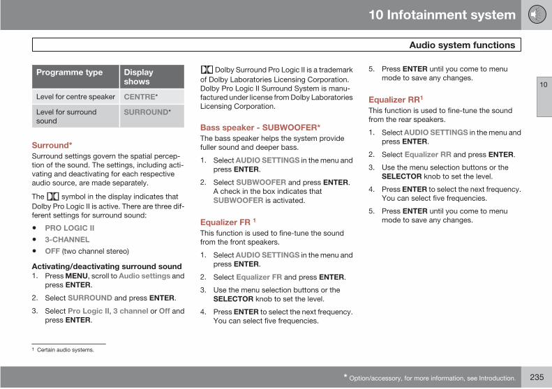
10 Infotainment system
Audio system functions
10
* Option/accessory, for more information, see Introduction. 235
Programme type Displayshows
Level for centre speaker CENTRE*
Level for surround
soundSURROUND*
Surround*
Surround settings govern the spatial percep-
tion of the sound. The settings, including acti-
vating and deactivating for each respective
audio source, are made separately.
The symbol in the display indicates that
Dolby Pro Logic II is active. There are three dif-
ferent settings for surround sound:
• PRO LOGIC II
• 3-CHANNEL
• OFF (two channel stereo)
Activating/deactivating surround sound1. Press MENU, scroll to Audio settings and
press ENTER.
2. Select SURROUND and press ENTER.
3. Select Pro Logic II, 3 channel or Off and
press ENTER.
Dolby Surround Pro Logic II is a trademark
of Dolby Laboratories Licensing Corporation.
Dolby Pro Logic II Surround System is manu-
factured under license from Dolby Laboratories
Licensing Corporation.
Bass speaker - SUBWOOFER*
The bass speaker helps the system provide
fuller sound and deeper bass.
1. Select AUDIO SETTINGS in the menu and
press ENTER.
2. Select SUBWOOFER and press ENTER.
A check in the box indicates that
SUBWOOFER is activated.
Equalizer FR 1
This function is used to fine-tune the sound
from the front speakers.
1. Select AUDIO SETTINGS in the menu and
press ENTER.
2. Select Equalizer FR and press ENTER.
3. Use the menu selection buttons or the
SELECTOR knob to set the level.
4. Press ENTER to select the next frequency.
You can select five frequencies.
5. Press ENTER until you come to menu
mode to save any changes.
Equalizer RR1
This function is used to fine-tune the sound
from the rear speakers.
1. Select AUDIO SETTINGS in the menu and
press ENTER.
2. Select Equalizer RR and press ENTER.
3. Use the menu selection buttons or the
SELECTOR knob to set the level.
4. Press ENTER to select the next frequency.
You can select five frequencies.
5. Press ENTER until you come to menu
mode to save any changes.
1 Certain audio systems.
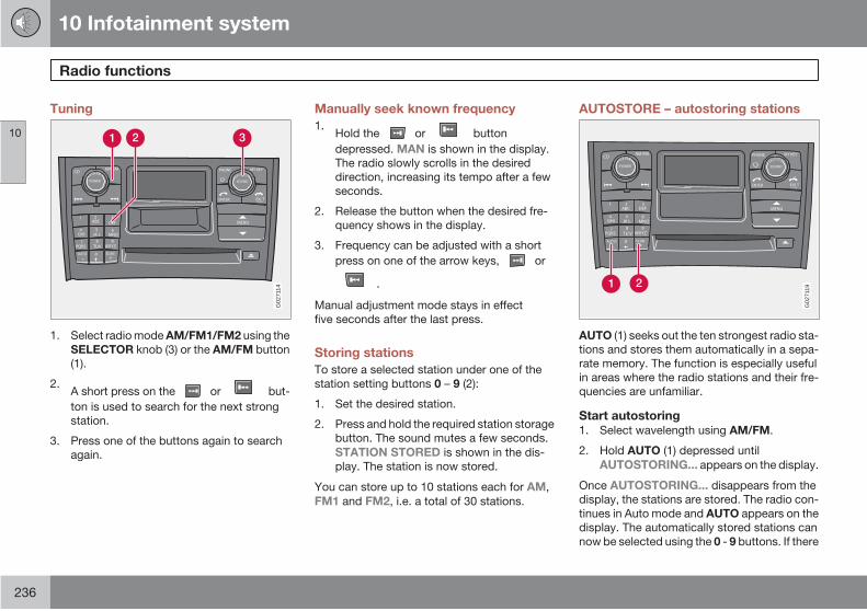
10 Infotainment system
Radio functions
10
236
Tuning
AM FM
WXYZ
*
AUTO 0
4
7PQRS
GHI5
JK L
TUV8
1ABC
2
POWER
VCD EMOLU
ESSOUND
#SCAN
6
9
MNO
DEF3
ENTER
PHONE
CLEAR
MENU
EXI T
MY KEYROCTLE
G02
7114
1. Select radio mode AM/FM1/FM2 using the
SELECTOR knob (3) or the AM/FM button
(1).
2.A short press on the or but-
ton is used to search for the next strong
station.
3. Press one of the buttons again to search
again.
Manually seek known frequency
1.Hold the or button
depressed. MAN is shown in the display.
The radio slowly scrolls in the desired
direction, increasing its tempo after a few
seconds.
2. Release the button when the desired fre-
quency shows in the display.
3. Frequency can be adjusted with a short
press on one of the arrow keys, or
.
Manual adjustment mode stays in effect
five seconds after the last press.
Storing stations
To store a selected station under one of the
station setting buttons 0 – 9 (2):
1. Set the desired station.
2. Press and hold the required station storage
button. The sound mutes a few seconds.
STATION STORED is shown in the dis-
play. The station is now stored.
You can store up to 10 stations each for AM,
FM1 and FM2, i.e. a total of 30 stations.
AUTOSTORE – autostoring stations
G02
7119
AUTO (1) seeks out the ten strongest radio sta-
tions and stores them automatically in a sepa-
rate memory. The function is especially useful
in areas where the radio stations and their fre-
quencies are unfamiliar.
Start autostoring1. Select wavelength using AM/FM.
2. Hold AUTO (1) depressed until
AUTOSTORING... appears on the display.
Once AUTOSTORING... disappears from the
display, the stations are stored. The radio con-
tinues in Auto mode and AUTO appears on the
display. The automatically stored stations can
now be selected using the 0 - 9 buttons. If there
10 Infotainment system
Radio functions
10
237
is no station with an adequately strong signal
then the display shows NO AST FOUND.
Cancelling automatic storage of stationsPress EXIT.
Selecting an autostored presetAllowing the radio to remain in Auto mode pro-
vides access to the autostored presets.
1. Briefly press AUTO (1). AUTO appears in
the display.
2. Press one of the 0 - 9 buttons.
3. The radio remains in Auto mode until it is
exited by a brief press on AUTO (1), EXIT
or AM/FM.
Scanning
SCAN (2) automatically searches through a
wavelength for strong stations. When a station
is found, it is played for approx. 8 seconds
before scanning is resumed.
Activating/deactivating Scan1. Select wavelength using AM/FM.
2. Press SCAN (2) to activate. SCAN appears
in the display.
3. Close using SCAN or EXIT.
Storing a stationA selected station can be stored as a preset
while SCAN is active.
Press one of the 0 - 9 buttons and hold it
depressed until the message Station
stored appears on the display.
SCAN is interrupted and the stored station can
be selected as a preset.
RDS functions
RDS (Radio Data System) links FM transmitters
into a network. An FM transmitter in such a
network sends information that gives an RDS
radio the following functions:
• Automatically switches to a stronger trans-mitter if reception in the area is poor.
• Searches for programme form, such astraffic information or news.
• Receives text information on the currentradio programme.
NOTE
Some radio stations do not use RDS or onlya selected range of its functions.
Volume control – NEWS/TP/ALARM
NOTE
If a CD for example is playing when the radioreceives a traffic bulletin, the CD player isput in pause mode. The message is playedat the volume selected for that type of mes-sage. Playback of the originally selectedaudio source is then resumed at the previ-ous volume. If volume is adjusted while thebulletin is played, the new volume is savedand used for the next bulletin.
News – NEWSThis function interrupts other sound sources,
e.g. CD, when a news broadcast starts.
1. Select radio mode using the SELECTOR
knob or the AM/FM button.
2. Select NEWS in the menu and press
ENTER.
3. NEWS appears on the display.
4. Select NEWS again and press ENTER to
deactivate the NEWS function.
With this function, programmes from RDS sta-
tions that are news-coded will interrupt other
audio sources using the volume setting for this
specific purpose. As soon as the news broad-
cast is finished, the audio system returns to the

10 Infotainment system
Radio functions
10
238
previous audio source and resumes the previ-
ous volume setting.
If you do not wish to listen to a news item in
progress:
Press the EXIT button. The NEWS function
remains active and the radio waits for the
next news programme.
Traffic information – TPThis function interrupts other audio sources in
order to broadcast traffic information from RDS
stations. The message is heard at the volume
set for this specific purpose. As soon as the
message ends, the radio returns to the previ-
ous audio source and volume setting.
1. Select TP in the menu and press ENTER.
2. TP appears on the display.
3. Select TP again and press ENTER to deac-
tivate the TP function.
TP is shown in the display when this function
is active. If the set station can send traffic infor-
mation then appears on the display.
Traffic information will only interrupt the sound
source if is shown in the display.
If you do not wish to listen to a traffic bulletin
in progress:
Press the EXIT button. The TP function
remains active and the radio waits for the
next traffic bulletin.
TP SearchThis function allows you to listen to traffic infor-
mation when travelling between different coun-
tries and states in Europe without needing to
select a station.
1. Select RADIO SETTINGS in the menu and
press ENTER.
2. Select TP and press ENTER.
3. Select TP Search and press ENTER.
To deactivate the function, select TP Searchagain and press ENTER.
Radio textSome RDS stations transmit information on
programme content, artists, etc. This informa-
tion can be indicated with text in the display.
1. Press the MENU button.
2. Select RADIO TEXT in the menu and
press ENTER.
3. Select RADIO TEXT again and press
ENTER to deactivate.
AlarmAlarms are transmitted automatically and the
function cannot be deactivated. Alarm! isshown in the radio display when an alarm mes-
sage is broadcast. This function is used to warn
motorists of major accidents and catastro-
phes, such as a bridge collapse or an accident
at a nuclear plant.
Programme types – PTY
The PTY function can be used to select differ-
ent programme types, such as pop or classical
music. Use the PTY function to select from
among the different programme types shown
in the list below.
Display of programme type1. Select RADIO SETTINGS in the menu and
press ENTER.
2. Select PTY in the menu and press
ENTER.
3. Select SHOW PTY and press ENTER.
The PTY of the selected station is now shown
in the display.
NOTE
Not all radio stations have a PTY designa-tion.
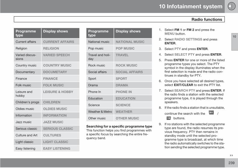
10 Infotainment system
Radio functions
10
239
Programmetype
Display shows
Current affairs CURRENT AFFAIRS
Religion RELIGION
Varied discus-
sionsVARIED SPEECH
Country music COUNTRY MUSIC
Documentary DOCUMETARY
Finance FINANCE
Folk music FOLK MUSIC
Leisure and
hobbyLEISURE & HOBBY
Children's progs CHILDREN
Oldies music OLDIES MUSIC
Information INFORMATION
Jazz music JAZZ MUSIC
Serious classic SERIOUS CLASSIC
Culture and Art CULTURES
Light classic LIGHT CLASSIC
Easy listening EASY LISTENING
Programmetype
Display shows
National music NATIONAL MUSIC
Pop music POP MUSIC
Travel and holi-
dayTRAVEL
Rock music ROCK MUSIC
Social affairs SOCIAL AFFAIRS
Sport SPORT
Drama DRAMA
Phone In PHONE IN
Education EDUCATION
Science SCIENCE
Weather & Metro WEATHER
Other music OTHER MUSIC
Searching for a specific programme typeThis function helps you find programmes with
a specific focus by searching the entire fre-
quency band.
1. Select FM 1 or FM 2 and press the
MENU button.
2. Select RADIO SETTINGS and press
ENTER.
3. Select PTY and press ENTER.
4. Select SELECT PTY and press ENTER.
5. Press ENTER for one or more of the listed
programme types you select. The PTY
symbol in the display illuminates when the
first selection is made and the radio con-
tinues in standby for PTY.
6. Once you have selected all desired types,
select EXIT/CLEAR to exit the PTY list.
7. Select SEARCH PTY and press ENTER. If
the radio finds a station with the selected
programme type, it is played through the
speakers.
8. If the radio finds a station that is unsuitable,
continue the search with the /
buttons.
9. If no stations with the selected programme
type are found, the radio resumes its pre-
vious frequency. PTY then remains in
standby mode until the selected pro-
gramme type is broadcast, at which time
the radio automatically switches to the sta-
tion sending the selected programme type.

10 Infotainment system
Radio functions
10
240
In order to deactivate PTY standby, enter the
menu and select CLEAR ALL PTY. The sym-
bol PTY disappears from the display and the
radio resumes normal mode.
Traffic information – TP STATION
Here, you set from which station traffic infor-
mation is to be heeded.
Note that must be shown in the display
for this to work.
Activating/deactivating TP STATIONListen to the station from which traffic informa-
tion is to be heeded.
1. Select RADIO SETTINGS in the menu and
press ENTER.
2. Select TP and press ENTER.
3. Select TP STATION and press ENTER.
4. Select SET CURRENT to activate or
RESET CURRENT to deactivate and
press ENTER.
NOTE
Now only traffic information from the storedstation will by played.
News – NEWS STATION
Here, you set from which station news is to be
heeded.
Note that the set station in question must be an
RDS station for this to work.
Activating/deactivating NEWS STATIONListen to the station from which news is to be
heeded.
1. Select RADIO SETTINGS in the menu and
press ENTER.
2. Select NEWS STATION and press
ENTER.
3. Select TP STATION and press ENTER.
4. Select SET CURRENT to activate or
RESET CURRENT to deactivate and
press ENTER.
NOTE
Now only news from the stored station willby played.
Automatic frequency update – AF
The AF function selects one of the strongest
transmitters for a set station. The radio may
sometimes need to search through the entire
FM wavelength to find a strong transmitter. If
this occurs, the radio mutes and PI SEEK
PRESS EXIT TO CANCEL appears in the dis-
play.
Activating/deactivating AF1. Select RADIO SETTINGS in the menu and
press ENTER.
2. Select AF and press ENTER.
To reactivate AF, select AF and press
ENTER.
Regional radio programmes – REG
This function causes the radio to continue with
a regional transmitter even if its signal strength
is low.
1. Select RADIO SETTINGS in the menu and
press ENTER.
2. Select REGIONAL and press ENTER.
3. REG appears on the display.
4. To deactivate the REG, select REG again
and press ENTER.
10 Infotainment system
Radio functions
10
241
Enhanced Other Networks – EON
The EON function is especially useful in urban
areas with many regional radio stations. It
allows the distance between the car and the
radio station transmitter to determine when
programme functions should interrupt the cur-
rent audio source.
• LOCAL – interrupts only if the radio stationtransmitter is close.
• DISTANT 1 – interrupts if the station trans-mitter is far away, even if there is a lot ofstatic.
• OFF – no interruption for programmes fromother transmitters.
Activating/deactivating EON1. Select RADIO SETTINGS in the menu and
press ENTER.
2. Select EON and press ENTER.
3. Select LOCAL, DISTANT or OFF and
press ENTER.
Resetting RDS functions
Resets all radio settings to the original factory
settings.
1. Select RADIO SETTINGS in the menu and
press ENTER.
2. Select RESET ALL and press ENTER.
3. Press ENTER again to confirm.
1 Default/factory settings.
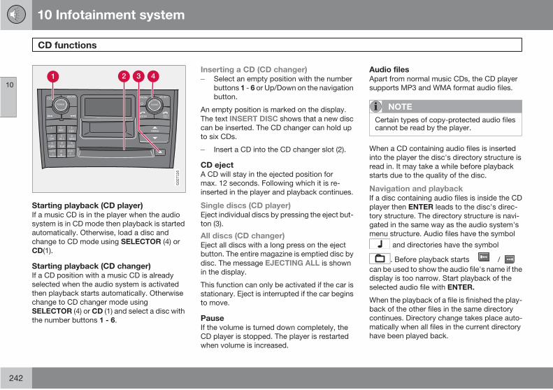
10 Infotainment system
CD functions
10
242
G02
7116
Starting playback (CD player)If a music CD is in the player when the audio
system is in CD mode then playback is started
automatically. Otherwise, load a disc and
change to CD mode using SELECTOR (4) or
CD(1).
Starting playback (CD changer)If a CD position with a music CD is already
selected when the audio system is activated
then playback starts automatically. Otherwise
change to CD changer mode using
SELECTOR (4) or CD (1) and select a disc with
the number buttons 1 - 6.
Inserting a CD (CD changer)Select an empty position with the number
buttons 1 - 6 or Up/Down on the navigation
button.
An empty position is marked on the display.
The text INSERT DISC shows that a new disc
can be inserted. The CD changer can hold up
to six CDs.
Insert a CD into the CD changer slot (2).
CD ejectA CD will stay in the ejected position for
max. 12 seconds. Following which it is re-
inserted in the player and playback continues.
Single discs (CD player)Eject individual discs by pressing the eject but-
ton (3).
All discs (CD changer)Eject all discs with a long press on the eject
button. The entire magazine is emptied disc by
disc. The message EJECTING ALL is shown
in the display.
This function can only be activated if the car is
stationary. Eject is interrupted if the car begins
to move.
PauseIf the volume is turned down completely, the
CD player is stopped. The player is restarted
when volume is increased.
Audio filesApart from normal music CDs, the CD player
supports MP3 and WMA format audio files.
NOTE
Certain types of copy-protected audio filescannot be read by the player.
When a CD containing audio files is inserted
into the player the disc's directory structure is
read in. It may take a while before playback
starts due to the quality of the disc.
Navigation and playbackIf a disc containing audio files is inside the CD
player then ENTER leads to the disc's direc-
tory structure. The directory structure is navi-
gated in the same way as the audio system's
menu structure. Audio files have the symbol
and directories have the symbol
/
can be used to show the audio file's name if the
display is too narrow. Start playback of the
selected audio file with ENTER.
When the playback of a file is finished the play-
back of the other files in the same directory
continues. Directory change takes place auto-
matically when all files in the current directory
have been played back.
. Before playback starts
10 Infotainment system
CD functions
10
243
Fast-wind/change CD tracks and audio
files
Short presses right/left on the /
buttons are used to scroll between CD tracks/
audio files. Long presses are used to fast-wind
CD tracks/audio files. The steering wheel key-
pad can also be used for this purpose.
Scan CDThis function plays the first ten seconds of
each CD track/audio file. Press SCAN to acti-
vate. Interrupt with EXIT or SCAN to continue
playback of the current CD track/audio file.
Scan only works on the selected disc. The text
SCAN is shown in the display when the func-
tion is active.
NOTE
If disc text is activated then SCAN is notshown in the display.
RandomThis function plays the tracks in random order.
The random CD tracks/audio files can be scrol-
led through in the normal way.
NOTE
It is only possible to scroll between randomCD tracks on the current disc.
Activating/deactivating (CD player)If a normal music CD is being played:
Select RANDOM in the menu and press
ENTER.
If a disc with audio files is being played:
Select DISC or FOLDER in the menu and
press ENTER.
Activating/deactivating (CD changer)If a normal music CD is being played:
1. Select Random in the menu and press
ENTER.
2. Scroll to SINGLE DISC or ALL DISCS and
press ENTER.
The option ALL DISCS only applies to the
music CDs in the changer.
If a CD with audio files is being played:
1. Select SINGLE DISC or FOLDER in the
menu and press ENTER.
2. Scroll to the required CD or folder and
press ENTER.
When you select another CD the function is
deactivated.
Different messages appear depending on
which random function is active:
• RANDOM means that the tracks from onlyone music CD are played.
• RND ALL means that all tracks on allmusic CDs in the CD changer are played.
• RANDOM FOLDER means that the audiofiles in a directory on the current CD areplayed.
NOTE
If disc text is activated then these messagesare not displayed.
Disc textIf title information is stored on a CD then it can
be shown in the display.
Activating/deactivatingStart CD playback.
Select DISCTEXT in the menu and press
ENTER.
CDsUsing CD discs burned at home could result in
poor or non-existent sound.
WARNING
Only use standard discs (12 cm in diameter).Do not use CDs with adhesive disc labels.The heat in the CD player may cause thelabel to come off, damaging the CD player.
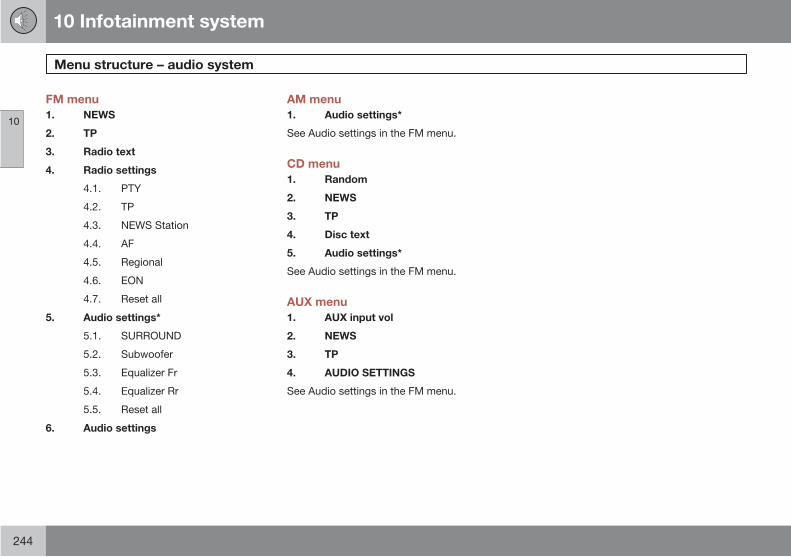
10 Infotainment system
Menu structure – audio system
10
244
FM menu
1. NEWS
2. TP
3. Radio text
4. Radio settings
4.1. PTY
4.2. TP
4.3. NEWS Station
4.4. AF
4.5. Regional
4.6. EON
4.7. Reset all
5. Audio settings*
5.1. SURROUND
5.2. Subwoofer
5.3. Equalizer Fr
5.4. Equalizer Rr
5.5. Reset all
6. Audio settings
AM menu
1. Audio settings*
See Audio settings in the FM menu.
CD menu
1. Random
2. NEWS
3. TP
4. Disc text
5. Audio settings*
See Audio settings in the FM menu.
AUX menu
1. AUX input vol
2. NEWS
3. TP
4. AUDIO SETTINGS
See Audio settings in the FM menu.

10 Infotainment system
Phone functions*
10
* Option/accessory, for more information, see Introduction. 245
EXITENTER
#0
*
DEF
MNO
WXYZPQRS7
GHI4
8TUV
5JKL
1 2ABC
9
6
3MENU
CLEAR
AM FMCD
V
POWER
EMOLUE
SOUNDS
PHONEROCTLE
MY KEY
3905624r
PHONE
ENTER EXITCLEAR
MY KEY
SOUND
G02
7002
Phone system components
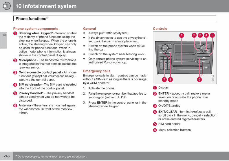
10 Infotainment system
Phone functions*
10
246 * Option/accessory, for more information, see Introduction.
Phone system components
Steering wheel keypad* - You can control
the majority of phone functions using the
steering wheel keypad. When the phone is
active, the steering wheel keypad can only
be used for phone functions. When in
active mode, phone information is always
shown in the control panel display.
Microphone - The handsfree microphone
is integrated in the roof console beside the
rearview mirror.
Centre console control panel - All phone
functions (except call volume) can be regu-
lated via the control panel.
SIM card reader - The SIM card is inserted
into the front of the control panel.
Privacy handset* - The privacy handset
can be used when you do not wish to be
disturbed.
Antenna - The antenna is mounted against
the windscreen, in front of the rearview
mirror.
General
• Always put traffic safety first.
• If the driver needs to use the privacy hand-set, park the car in a safe place first.
• Switch off the phone system when refuel-ling the car.
• Switch off the system near blasting work.
• Only entrust phone system servicing to anauthorised Volvo workshop.
Emergency calls
Emergency calls to alarm centres can be made
without a SIM card as long as there is coverage
by a GSM operator.
1. Activate the phone.
2. Ring the emergency number that applies to
your region (within EU: 112).
3. Press ENTER in the control panel or in the
steering wheel keypad.
Controls
G02
7117
Display
ENTER – accept a call, make a menu
selection or activate the phone from
standby mode
On/Off/Standby
EXIT/CLEAR – terminate/refuse a call,
scroll back in the menu, cancel a selection
or erase entered digits/characters
SIM card holder
Menu selection buttons

10 Infotainment system
Phone functions*
10
* Option/accessory, for more information, see Introduction. 247
G02
7004
Number/character buttons and menu
shortcuts
Seek – scroll forward or back when enter-
ing text and numbers
Increase/decrease call volume during
calls. The phone does not use the centre
speaker*
On/Off/Standby switch
To activate the system:
Press the PHONE button (3) to activate the
phone system.
To switch off the system:
Hold the PHONE button depressed to
Continuing with system in standby mode:
1. The phone will continue in standby mode
with a brief press of the PHONE button or
if you press EXIT/CLEAR.
2. Reactivate the system with the PHONE
button.
When the phone is active or in standby mode,
a handset is shown in the display.
NOTE
With the Performance audio system (stand-ard level), it is not possible to listen to theradio, CD or receive traffic messages duringa phone call.
If you switch off the car's ignition with the
phone system on, it will be on the next time you
switch on the ignition. No calls can be received
when the phone system is switched off.
Volume reduction during phone call
If the phone rings when the radio is switched
on, the volume is lowered when the call is
answered. When the call is concluded, the vol-
ume returns to the previously set level. Radio
volume can also be adjusted during a phone
call, whereby the newly selected level will
resume when the call is concluded. Audio sys-
tem volume can also be switched off com-
pletely during a phone call, see page 259.
This function only applies to the Volvo inte-
grated phone system.
Standby mode
In standby mode, you can receive calls while
the audio system is active and information from
audio system sources is shown in the display.
To use other functions of the phone system,
the phone must be in active mode.
Menu shortcuts
Once you have used the menu button to enter
the menu system, you can use numbers
instead of the arrows and the ENTER button to
select the right menu in the main menu level.
Each menu selection is numbered. The num-
bers are shown in the display together with the
menu alternative.
switch off the phone system.

10 Infotainment system
Phone functions*
10
248 * Option/accessory, for more information, see Introduction.
Traffic safety
For reasons of safety, parts of the phone menu
system cannot be accessed at speeds in
excess of 8 km/h. You may only complete
menu system activities that have already been
started.
The speed limiter can be disconnected using
menu function 5.6.
SIM card
G02
6980
The phone can only be used with a valid SIM
card Subscriber Identity Module. Your network
operator supplies this card.
Always insert the SIM card when you wish to
use the phone.
1. Switch off the phone.
2. Open the SIM card holder with a short
press.
3. Insert the SIM card with the metallic sur-
face down.
4. Make sure that the bevelled corner of the
SIM card matches the bevel of the holder.
5. Press in the holder.
Contact your network operator if you experi-
ence difficulties with the SIM card.
Making and receiving calls
To call:
Dial the number and press ENTER on the
steering wheel or the control panel keypad
(or lift the handset).
To receive an incoming call:
Press ENTER or lift the handset. You can
also use Automatic Answer, see
page 259.
The car's audio system can be muted auto-
matically while a phone call is in progress, see
page 259.
Ending a call
Press EXIT/CLEAR on the steering wheel
or control panel keypad or hang up the
handset.
The audio system resumes its previous activity.
Refuse an incoming call by pressing EXIT/
CLEAR.
Privacy handset
If you wish to speak without disruptions, use
the privacy handset. Lift the handset by press-
ing briefly on the top (A).
G02
6983
Select the desired phone number using the
centre console keypad and lift the handset
10 Infotainment system
Phone functions*
10
* Option/accessory, for more information, see Introduction. 249
to place the call. Adjust the volume with the
dial on the side of the handset.
The call is ended when you replace the handset
in its holder.
If you wish to switch to handsfree without end-
ing the call:
1. Press on the steering wheel keypad
(or control panel menu buttons) and select
Handsfree.
2. Press ENTER and hang up the handset. If
the handset is already removed from its
cradle when a call is started, the ringing
party will be audible in the handsfree sys-
tem.
3. Press the MENU button, scroll to Handset
and press ENTER in order to transfer to the
handset.
Last dialled numbers
The phone automatically stores the last phone
numbers/names called.
1. Press ENTER on the steering wheel or
control panel keypad.
2. Use the menu buttons to scroll forward or
back through the last numbers dialled.
They are shown in the display.
3. Press ENTER.
Speed dial
Storing speed dial numbersA number stored in the phone book can be
linked to a speed dial button (1 – 9).
Proceed as follows:
1. Select Phone book in the menu and press
ENTER.
2. Scroll to Speed dial (see page 259) and
press ENTER.
3. Select which number is to be the speed dial
number. Press ENTER to confirm.
4. Search for the desired name or phone
number in the phone book. Press ENTER
to select.
Using speed dial1. To make a call, press and hold the desired
speed dial button for about two seconds or
press the button briefly and then press
ENTER.
2. Once you switch on the phone, wait a
moment before using speed dial.
NOTE
If you wish to use a speed dial number thenMenu 3.4 must be activated. See Speed dialunder Description of menu options on page258.
Call waiting
If you hear two beeps in your speaker during a
phone call, someone else is calling. This func-
tion can be selected or deselected in the menu.
When this occurs, you may accept or decline
the call. If you do not wish to take the call, press
EXIT/CLEAR or do nothing.
If you do wish to take the call, press ENTER.
Your current call will be put in "park mode". If
you press EXIT/CLEAR, both calls will be ter-
minated.
Functions during a call
The following functions are available during a
call (scroll with the arrows and press ENTER to
make a selection)
Secret mode/
Secret mode off
Secret mode
Hold/Resume Choose if the call is
to be parked or
resumed.
Handset/Hands-
free
Using the handset or
handsfree
Phone book Show phone book
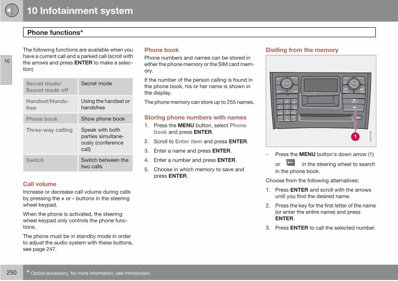
10 Infotainment system
Phone functions*
10
250 * Option/accessory, for more information, see Introduction.
The following functions are available when you
have a current call and a parked call (scroll with
the arrows and press ENTER to make a selec-
tion)
Secret mode/
Secret mode off
Secret mode
Handset/Hands-
free
Using the handset or
handsfree
Phone book Show phone book
Three-way calling Speak with both
parties simultane-
ously (conference
call)
Switch Switch between the
two calls
Call volume
Increase or decrease call volume during calls
by pressing the + or - buttons in the steering
wheel keypad.
When the phone is activated, the steering
wheel keypad only controls the phone func-
tions.
The phone must be in standby mode in order
to adjust the audio system with these buttons,
see page 247.
Phone book
Phone numbers and names can be stored in
either the phone memory or the SIM card mem-
ory.
If the number of the person calling is found in
the phone book, his or her name is shown in
the display.
The phone memory can store up to 255 names.
Storing phone numbers with names
1. Press the MENU button, select Phone
book and press ENTER.
2. Scroll to Enter item and press ENTER.
3. Enter a name and press ENTER.
4. Enter a number and press ENTER.
5. Choose in which memory to save and
press ENTER.
Dialling from the memory
AM FM
WXYZ
*
AUTO 0
4
7PQRS
GHI5
JK L
TUV8
1ABC
2
POWER
VCD EMOLU
ESSOUND
#SCAN
6
9
MNO
DEF3
ENTER
PHONE
CLEAR
MENU
EXI T
MY KEYROCTLE
G02
7118
Press the MENU button's down arrow (1)
or in the steering wheel to search
in the phone book.
Choose from the following alternatives:
1. Press ENTER and scroll with the arrows
until you find the desired name.
2. Press the key for the first letter of the name
(or enter the entire name) and press
ENTER.
3. Press ENTER to call the selected number.
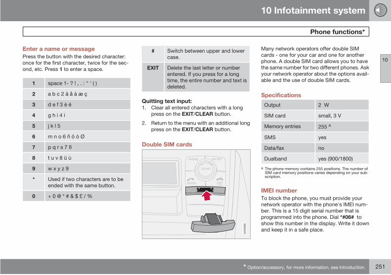
10 Infotainment system
Phone functions*
10
* Option/accessory, for more information, see Introduction. 251
Enter a name or message
Press the button with the desired character:
once for the first character, twice for the sec-
ond, etc. Press 1 to enter a space.
1 space 1- ? ! , . : " ' ( )
2 a b c 2 ä å à æ ç
3 d e f 3 è é
4 g h i 4 ì
5 j k l 5
6 m n o 6 ñ ö ò Ø
7 p q r s 7 ß
8 t u v 8 ü ù
9 w x y z 9
* Used if two characters are to be
ended with the same button.
0 + 0 @ * # & $ £ / %
# Switch between upper and lower
case.
EXIT Delete the last letter or number
entered. If you press for a long
time, the entire number and text is
deleted.
Quitting text input:1. Clear all entered characters with a long
press on the EXIT/CLEAR button.
2. Return to the menu with an additional long
press on the EXIT/CLEAR button.
Double SIM cards
G02
6980
Many network operators offer double SIM
cards - one for your car and one for another
phone. A double SIM card allows you to have
the same number for two different phones. Ask
your network operator about the options avail-
able and the use of double SIM cards.
Specifications
Output 2 W
SIM card small, 3 V
Memory entries 255 A
SMS yes
Data/fax no
Dualband yes (900/1800)
A The phone memory contains 255 positions. The number ofSIM card memory positions varies depending on your sub-scription.
IMEI number
To block the phone, you must provide your
network operator with the phone's IMEI num-
ber. This is a 15 digit serial number that is
programmed into the phone. Dial *#06# to
show this number in the display. Write it down
and keep it in a safe place.
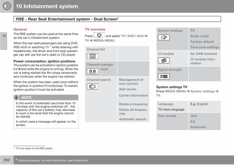
10 Infotainment system
RSE - Rear Seat Entertainment system - Dual Screen*
10
252 * Option/accessory, for more information, see Introduction.
General
The RSE system can be used at the same time
as the car's infotainment system.
When the rear seat passengers are using DVD,
RSE-AUX or watching TV 1 while listening with
headphones, the driver and front seat passen-
ger can still use the car's radio or CD player.
Power consumption, ignition positionsThe system can be activated in ignition position
I or II and while the engine is running. When the
car is being started the film stops temporarily
and continues when the engine has started.
When the system has been used once without
the ignition in position I it is blocked. To restart,
ignition position I must be activated.
NOTE
In the event of extended use (more than 10minutes) with the engine switched off - thecapacity of the car's battery may decreaseto such a low level that the engine cannotbe started.
In which case a message will appear on thescreen.
TV overview
Press and select TV I DVD I AUX
TV MEDIA MENU.
Channel list
Channel search
Delete a frequency
Delete all frequen-
cies
Automatic search
System settings TV
Time zone settings
CI module No CAM inserted
CI module infor-
mation
Signal strength
System settings TV
Press MEDIA MENU System settings
TV.
Language
TV menu language
E.g. English
16:9
4:3
Automatic
1 TV is an option for the RSE system.
Channel manage-
ment
Management of
new carriers
Add carrier
Audio mode
Factory default
Pict. format
Carrier information

10 Infotainment system
RSE - Rear Seat Entertainment system - Dual Screen*
10
* Option/accessory, for more information, see Introduction. 253
Mode (screen
mode)
Basic
Zoom
Full screen
Centred
Right
Left
displayed for
between
8-40 seconds.
System settings-Sound mode
Press MEDIA MENU System settings
The original speech for a TV programme can
be replaced with speech in another language if
the programme is broadcast with several audio
tracks.
ENG.
GER.
Sound mode Right
Left
Stereo
AC3
System settings-Factory settings
Press MEDIA MENU System settings
The system's factory settings are restored
here.
System settings-Time zone settings
Press MEDIA MENU System settings
Time zone settings.
For local programme times to be displayed
correctly the time zone must be set. The
GUIDE and INFO button menus and the clock
are affected by local time zones.
Pay channelsTo watch pay channels a payment card must
be fitted in an adapter which is inserted into the
digital TV box.
G03
1511
The digital TV box is located on the right-hand
side of the cargo area
1. The box is protected by a cover. Open the
small hatch above the cover.
2. Open the rubber cover on the box.
3. Fit the payment card into the adapter.
Make sure that it is fitted correctly.
4. Insert the adapter in the digital TV box.
Make sure that it is inserted correctly.
> The system will detect that it has
received new information.
5. Search to find the new channels that have
become available, see the section "Pay-
ment card TV channels" below.
Audio mode
Banner timeout
The menus can be
Audio mode
Audio - 2, e.g.
Audio - 1, e.g.
Factory default.
Audio mode.
10 Infotainment system
RSE - Rear Seat Entertainment system - Dual Screen*
10
254 * Option/accessory, for more information, see Introduction.
Payment card TV channelsSearch so that the system identifies the pay-
ment card's channels.
1. Press MEDIA MENU on the remote con-
trol.
2. Select Channel search Automatic
search.
3.Select country and press .
Formats supported by the digital TV boxThe TV system supports MPEG-2 transmis-
sions. There is the option to receive
MPEG-4 transmissions if you buy an adapter.
This adapter is inserted into the digital TV box
and is fitted in the same way as the adapter for
the payment card. See the section "Pay chan-
nels" above.
Music
Playing back a CD disc1. Insert the CD with the label side turned
from the buttons.
> The disc starts to play back automati-
cally.
2. Switch on the wireless headphones, select
CH A for left-hand screen or CH B for right-
hand screen.
> The sound is directed to the head-
phones.
3. Adjust the audio volume in the headphones
using the volume control/wheel on the
headphones.
Alternatively - activate the car's audio sys-
tem in MODE-AUX and press A B on
the remote control to listen via the speak-
ers.
Selecting within a disc directory1. Load the disc.
2.Press .
3. Scroll using the navigation buttons to
select a file.
4.Press to select the subdirectory.
Different playback optionsThe disc can be played back in different ways,
scroll with the navigation buttons to select
playback option.
When the dialogue box appears:
1. Press the right-hand navigation button to
move over in the right-hand menu.
2. Scroll using the navigation buttons to
select playback options.
3.Confirm with .
Change CD track
Change CD track with or
fast-wind by holding the buttons
depressed.
Pause1.
Pause and restart the disc with .
2.Stop the disc with .
3.Press again to eject the disc.
Discs copied privately can be used.However, playback and quality depend on the
quality of the source file, format and disc qual-
ity.
AUX input, Electrical socket 12 V
The input allows you to connect other equip-
ment. Always follow the instructions included
with the external equipment, or from the man-
ufacturer or reseller, when connecting. Equip-
ment connected via the RSE AUX input can use
the screens, wireless headphones, head-
phones sockets and the car's speakers.

10 Infotainment system
RSE - Rear Seat Entertainment system - Dual Screen*
10
* Option/accessory, for more information, see Introduction. 255
Connecting the RSE AUX input
G015700
The RSE-AUX input is located in the centre con-sole under the DVD player.
1. Connect the video cable to the yellow
socket.
2. Connect the left-hand audio cable to the
white socket and the right-hand one to the
red socket.
3. Connect the power cable to the power
socket if your equipment is designed for
12 V.
System
Formats supported by the system.
Audio
format
CD-DA, DVD Audio Playback,
MP3, WMA
Video
format
DVD video, VCD, SVCD, DivX/
MPEG-4, WMA video, Photo CD
Kodak, Photo CD JPG
Disc
format
DVD-RAM, DVD-ROM, DVD-RW,
DVD+RW, DVD-R, DVD+R, CD-R,
CD-ROM, CD-RW, CD-3, HDCD
Advanced system settingsThese settings can only be accessed when the
DVD player is empty.
Press MEDIA MENU.
GENERAL SETUP ANGLE MARK
CAPTION
AUDIO SETUP COMPRESSION
DVX(R)
REGISTRATION
PREFERENCES TV TYPE
AUDIO
SUBTITLE
DEFAULTS
Changing the battery in the remotecontrol and wireless headphones
The remote control and headphones are pow-
ered by 2 AAA batteries.
Take along extra batteries for a long journey.
G03
1359
Remote control
1. Unscrew the screw and detach the battery
cover.
2. Remove the used batteries, turn the new
batteries in accordance with the symbols
in the battery compartment and insert
them.
3. Fit the cover and screw in the screw.
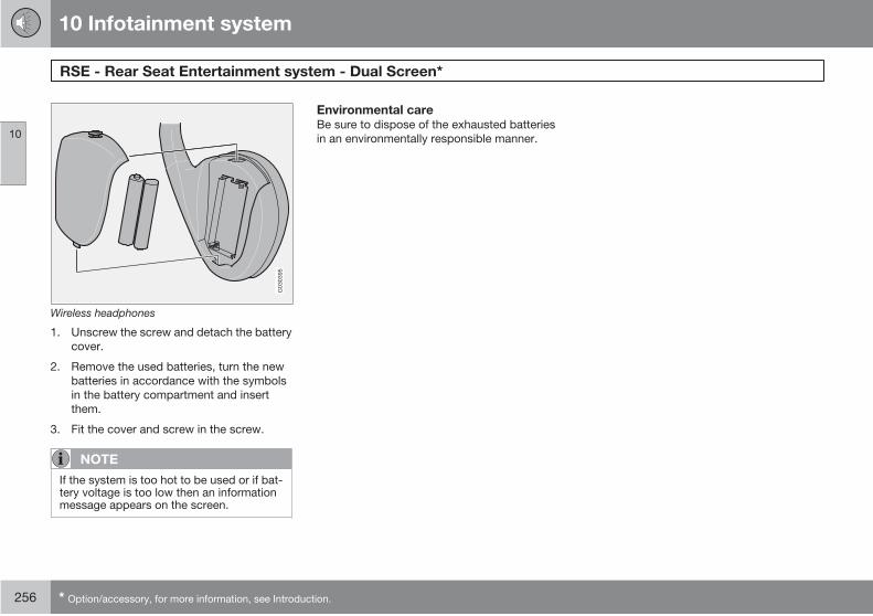
10 Infotainment system
RSE - Rear Seat Entertainment system - Dual Screen*
10
256 * Option/accessory, for more information, see Introduction.
G03
0395
Wireless headphones
1. Unscrew the screw and detach the battery
cover.
2. Remove the used batteries, turn the new
batteries in accordance with the symbols
in the battery compartment and insert
them.
3. Fit the cover and screw in the screw.
NOTE
If the system is too hot to be used or if bat-tery voltage is too low then an informationmessage appears on the screen.
Environmental careBe sure to dispose of the exhausted batteries
in an environmentally responsible manner.
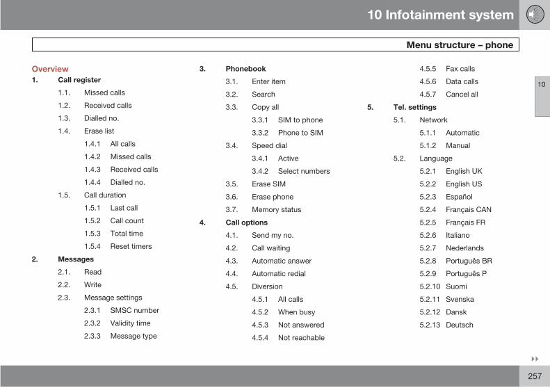
10 Infotainment system
Menu structure – phone
10
257
Overview
1. Call register
1.1. Missed calls
1.2. Received calls
1.3. Dialled no.
1.4. Erase list
1.4.1 All calls
1.4.2 Missed calls
1.4.3 Received calls
1.4.4 Dialled no.
1.5. Call duration
1.5.1 Last call
1.5.2 Call count
1.5.3 Total time
1.5.4 Reset timers
2. Messages
2.1. Read
2.2. Write
2.3. Message settings
2.3.1 SMSC number
2.3.2 Validity time
2.3.3 Message type
3. Phonebook
3.1. Enter item
3.2. Search
3.3. Copy all
3.3.1 SIM to phone
3.3.2 Phone to SIM
3.4. Speed dial
3.4.1 Active
3.4.2 Select numbers
3.5. Erase SIM
3.6. Erase phone
3.7. Memory status
4. Call options
4.1. Send my no.
4.2. Call waiting
4.3. Automatic answer
4.4. Automatic redial
4.5. Diversion
4.5.1 All calls
4.5.2 When busy
4.5.3 Not answered
4.5.4 Not reachable
4.5.5 Fax calls
4.5.6 Data calls
4.5.7 Cancel all
5. Tel. settings
5.1. Network
5.1.1 Automatic
5.1.2 Manual
5.2. Language
5.2.1 English UK
5.2.2 English US
5.2.3 Español
5.2.4 Français CAN
5.2.5 Français FR
5.2.6 Italiano
5.2.7 Nederlands
5.2.8 Português BR
5.2.9 Português P
5.2.10 Suomi
5.2.11 Svenska
5.2.12 Dansk
5.2.13 Deutsch

10 Infotainment system
Menu structure – phone
10
258
5.3. SIM security
5.3.1 On
5.3.2 Off
5.3.3 Automatic
5.4. Edit codes
5.4.1 PIN code
5.4.2 Phone code
5.5. Volume
5.5.1 Ring volume
5.5.2 Ring signal
5.5.3 Mute radio
5.5.4 Msg. beep
5.6. Traff. safety
5.6.1 Menu lock
5.6.2 IDIS
5.7. Factory sett.
Description of menu options
1. Call register
1.1. Missed callsList of missed calls. You can choose to call,
erase or store the number in the phone book.
1.2. Received callsList of received calls. You can choose to call,
erase or store the number in the phone book.
1.3. Dialled no.List of dialled numbers. You can choose to call,
erase or store the number in the phone book.
1.4. Erase listErase the lists found in the menus 1.1, 1.2 and
1.3 as below.
1.4.1. All
1.4.2. Missed
1.4.3. Received
1.4.4. Dialled
1.5. Call durationDuration of all calls or of the most recent call.
The phone code is required to reset the call
timer (see menu 5.4).
1.5.1. Last call
1.5.2. Call count
1.5.3. Total time
1.5.4. Reset timers
2. Messages
2.1. ReadReceived text messages. Select whether to
erase, forward, change or save the entire mes-
sage or parts of it.
2.2. WriteWrite a message using the keypad. Choose
whether to save or send it.
2.3. Message settingsEnter the number (SMSC number) of the mes-
sage centre to which messages are to be trans-
ferred as well as how long they are to be saved
at the message centre. Contact your network
operator for information on message settings.
Normally, these settings should not be altered.
2.3.1. SMSC number
2.3.2. Validity time
2.3.3. Message type
3. Phone book
3.1. New numberStore names and phone numbers in the phone
book, see page 249.
3.2. SearchSearch for a name in the phone book.

10 Infotainment system
Menu structure – phone
10
259
3.3. Copy allCopy phone numbers and names from the SIM
card to the phone memory.
3.3.1. From SIM to phone memory
3.3.2. From phone to SIM memory
3.4. Speed dialA number stored in the phone book can be
stored as a speed dial number.
3.5. Erase SIMErase the entire SIM card memory.
3.6. Erase phoneErase the entire phone memory.
3.7. Memory statusShows how many positions are occupied in the
SIM card and phone memory. The table shows
how many of the total number of positions are
occupied, e.g. 100 (250).
4. Call options
4.1. Send my no.Displays or hides your phone number to/from
the person you call. Contact your network
operator regarding ex-directory numbers.
4.2. Call waitingBe alerted during a phone call that there is
another incoming call.
4.3. Automatic answerAutomatically answers incoming calls.
4.4. Call backCalls a previously engaged number.
4.5. DiversionChoose when and what type of calls are to be
diverted to a specified phone number.
4.5.1. All calls (this setting only applies during
the call in progress)
4.5.2. When busy
4.5.3. Not answered
4.5.4. Not reachable
4.5.5. Fax calls
4.5.6. Data calls
4.5.7. Cancel all
5. Phone settings
5.1. NetworkChoose a network automatically or manually.
The selected network is shown in the display in
the phone's basic mode.
5.1.1. Auto
5.1.2. Manual
5.2. LanguageSelect the phone language.
5.2.1. English UK
5.2.2. English US
5.2.3. Español
5.2.4. Français CAN
5.2.5. Français FR
5.2.6. Italiano
5.2.7. Nederlands
5.2.8. Português BR
5.2.9. Português P
5.2.10. Suomi
5.2.11. Svenska
5.2.12. Dansk
5.2.13. Deutsch
5.3. SIM securitySelect if the PIN code should be on, off or if the
phone should automatically give the PIN code.
5.3.1. On
5.3.2. Off
5.3.3. Automatic
5.4. Edit codesChange PIN or phone code. Write the codes
down and keep them in a safe place.
5.4.1. PIN code
5.4.2. Phone code. The factory-set phone
code 1234 is used until you change to
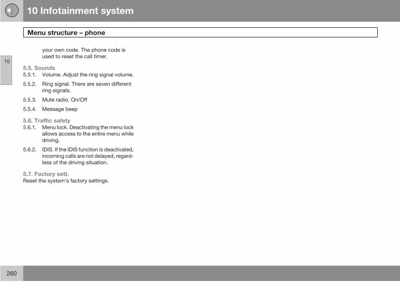
10 Infotainment system
Menu structure – phone
10
260
your own code. The phone code is
used to reset the call timer.
5.5. Sounds5.5.1. Volume. Adjust the ring signal volume.
5.5.2. Ring signal. There are seven different
ring signals.
5.5.3. Mute radio. On/Off
5.5.4. Message beep
5.6. Traffic safety5.6.1. Menu lock. Deactivating the menu lock
allows access to the entire menu while
driving.
5.6.2. IDIS. If the IDIS function is deactivated,
incoming calls are not delayed, regard-
less of the driving situation.
5.7. Factory sett.Reset the system's factory settings.

10 Infotainment system
10
261
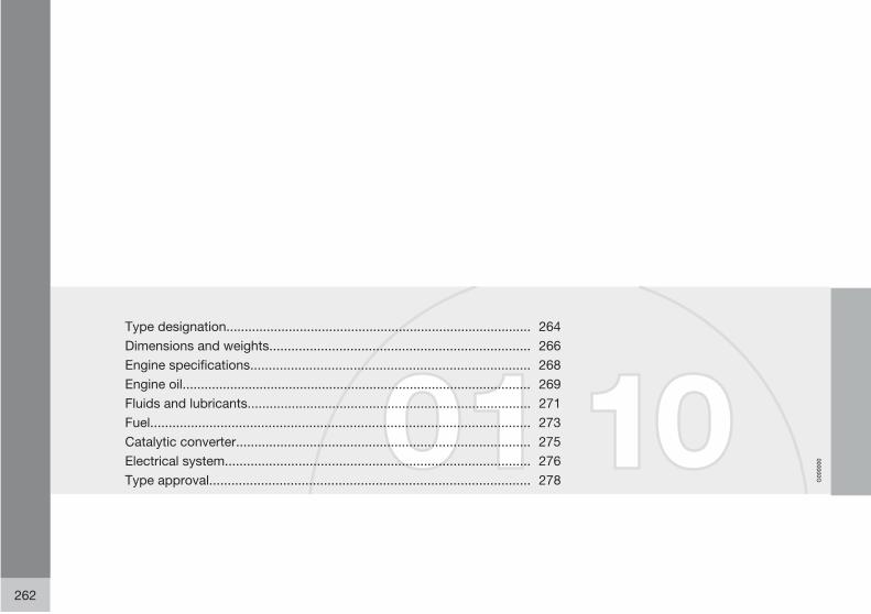
G00
0000
262
Type designation................................................................................... 264
Dimensions and weights....................................................................... 266
Engine specifications............................................................................ 268
Engine oil............................................................................................... 269
Fluids and lubricants............................................................................. 271
Fuel....................................................................................................... 273
Catalytic converter................................................................................ 275
Electrical system................................................................................... 276
Type approval....................................................................................... 278

11SPECIF ICATIONS
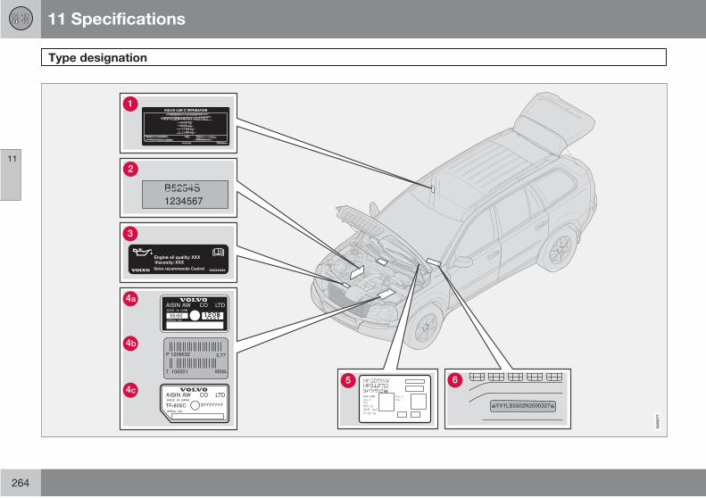
11 Specifications
Type designation
11
264
G03
2077
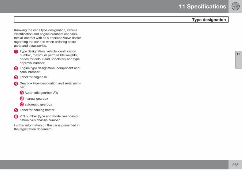
11 Specifications
Type designation
11
265
Knowing the car's type designation, vehicle
identification and engine numbers can facili-
tate all contact with an authorised Volvo dealer
regarding the car and when ordering spare
parts and accessories.
Type designation, vehicle identification
number, maximum permissible weights,
codes for colour and upholstery and type
approval number.
Engine type designation, component and
serial number.
Label for engine oil.
Gearbox type designation and serial num-
ber:
Automatic gearbox AW
manual gearbox
automatic gearbox
Label for parking heater.
VIN number (type and model year desig-
nation plus chassis number).
Further information on the car is presented in
the registration document.
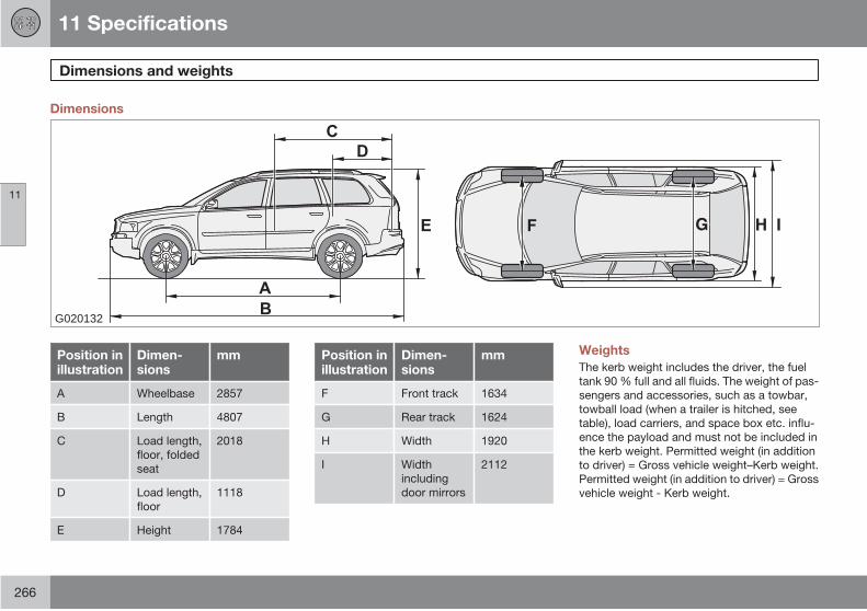
11 Specifications
Dimensions and weights
11
266
Dimensions
G020132
Position inillustration
Dimen-sions
mm
A Wheelbase 2857
B Length 4807
C Load length,
floor, folded
seat
2018
D Load length,
floor
1118
E Height 1784
Position inillustration
Dimen-sions
mm
F Front track 1634
G Rear track 1624
H Width 1920
I Width
including
door mirrors
2112
Weights
The kerb weight includes the driver, the fuel
tank 90 % full and all fluids. The weight of pas-
sengers and accessories, such as a towbar,
towball load (when a trailer is hitched, see
table), load carriers, and space box etc. influ-
ence the payload and must not be included in
the kerb weight. Permitted weight (in addition
to driver) = Gross vehicle weight–Kerb weight.
Permitted weight (in addition to driver) = Gross
vehicle weight - Kerb weight.

11 Specifications
Dimensions and weights
11
267
WARNING
The car's driving characteristics changedepending on how heavily it is loaded andhow the load is distributed.
G01
6008
See decal location on see page 264.
Max. total weight
Max. train weight (car+trailer)
Max. front axle load
Max. rear axle load
Equipment level
Max. load: See registration document.
Maximum roof load: 100 kg
Trailer with brakes:
Maximum trailerweight kg
Maximum tow-ball load kg
2250 90
Trailer without brakes
Maximum trailerweight kg
Maximum tow-ball load kg
750 50

11 Specifications
Engine specifications
11
268
2.5T* V8 3.2 D5 2.4D A
Engine designation B B5254T2 B8444S B6324S D5244T4 D5244T5
Output (kW/rpm) 154/4980 232/5850 175/6200 136/4000 120/4000
(hp/rpm) 210/5000 315/5850 238/6200 185/4000 163/4000
Torque (Nm/rpm) 320/1500-4500 440/3900 320/3200 400/2000-2760 340/1750-2750
No. of cylinders 5 8 6 5 5
Bore (mm) 83 94 84 81 81
Stroke (mm) 93.2 79.5 96 93.2 93,1
Swept volume (litres) 2.52 4.41 3.2 2.40 2,400
Compression ratio 9.0:1 10.4:1 10.8:1 17.0:1 17.0:1
A Only BelgiumB Engine type designation, component and serial number can be read on the engine, see page 264.

11 Specifications
Engine oil
11
269
Adverse driving conditions
Check the oil level more frequently for long
journeys:
• towing a caravan or trailer.
• in mountainous regions.
• at high speeds.
• in temperatures colder than -30 °C or hot-ter than +40 °C.
This can produce abnormally high oil tempera-
ture or oil consumption.
Also check the oil level more often if the car is
often driven short distances (less than 10 km)
when temperatures are low (below +5 °C).
Choose a fully synthetic engine oil for adverse
driving conditions. It provides extra protection
for the engine.
Volvo recommends Castrol oil products.
IMPORTANT
In order to fulfil the requirements for theengine's service intervals all engines arefilled with a specially adapted syntheticengine oil at the factory. The choice of oilhas been made very carefully with regard toservice life, starting characteristics, fuelconsumption and environmental impact. Anapproved engine oil must be used in orderthat the recommended service intervals canbe applied. Only use a prescribed grade ofoil (see the engine compartment decal) forboth filling and oil change, otherwise youwill risk affecting service life, starting cha-racteristics, fuel consumption and environ-mental impact. Volvo Car Corporation dis-claims all warranty liability if engine oil of theprescribed grade and viscosity is not used.
Viscosity chart
G02
0236

11 Specifications
Engine oil
11
270
Oil decal
Engine variant Filling volumebetween MIN–MAX (litres)
Volume A (litres)
G03
2078
The following applies when this adjacent oil
decal is fitted in the car's engine compartment.
For placement, see page 264.
Oil grade: ACEA A5/B5
Viscosity: SAE 0W–30
2.5T B5254T2 1.2 5.5
3.2 B6324S 1.2 7.4
V8 AWD B8444S 1.2 6.7
D5 AWD D5244T4 2.0 6.2
2.4D B D5244T5 1.5 6.0
A Including filter change.B Only Belgium
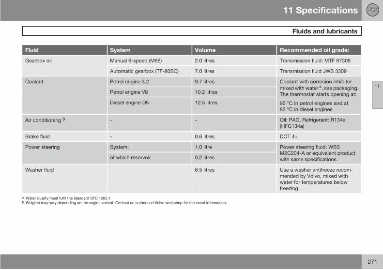
11 Specifications
Fluids and lubricants
11
271
Fluid System Volume Recommended oil grade:
Gearbox oil Manual 6-speed (M66) 2.0 litres Transmission fluid: MTF 97309
Automatic gearbox (TF-80SC) 7.0 litres Transmission fluid JWS 3309
Coolant Petrol engine 3.2 9.7 litres Coolant with corrosion inhibitor
mixed with water A, see packaging.
The thermostat starts opening at:
90 °C in petrol engines and at
82 °C in diesel engines
Petrol engine V8 10.2 litres
Diesel engine D5 12.5 litres
Air conditioning B - - Oil: PAG, Refrigerant: R134a
(HFC134a)
Brake fluid - 0.6 litres DOT 4+
Power steering System: 1.0 litre Power steering fluid: WSS
M2C204-A or equivalent product
with same specifications.of which reservoir 0.2 litres
Washer fluid 6.5 litres Use a washer antifreeze recom-
mended by Volvo, mixed with
water for temperatures below
freezing.
A Water quality must fulfil the standard STD 1285.1.B Weights may vary depending on the engine variant. Contact an authorised Volvo workshop for the exact information.

11 Specifications
Fluids and lubricants
11
272
IMPORTANT
The recommended transmission fluid mustbe used to prevent damage to the gearbox.Do not mix with any other transmission fluid.If the transmission is topped up with a dif-ferent fluid, contact an authorised Volvoworkshop for servicing.
NOTE
Under normal driving conditions the gear-box oil does not need changing during itsservice life. However, it may be necessaryunder adverse driving conditions, seepage 269.
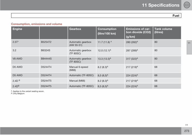
11 Specifications
Fuel
11
273
Consumption, emissions and volume
Engine Gearbox Consumption
(litre/100 km)
Emissions of car-bon dioxide (CO2)
(g/km)
Tank volume(litres)
2.5T* B5254T2 Automatic gearbox
(AW 55-51)11.7 (11.8) A 280 (282)A 80
3.2 B6324S Automatic gearbox
(TF 80SC)12.0 (12.1)A 287 (289)A 80
V8 AWD B84444S Automatic gearbox
(TF 80SC)13.3 (13.5)A 317 (322)A 80
D5 AWD D5244T4 Manual 6-speed
(M66)8.2 (8.3)A 217 (219)A 68
D5 AWD D5244T4 Automatic (TF-80SC) 8,5 (8,5)A 224 (224)A 68
2.4D B D5244T5 Manual (M66) 8.2 (8.3)A 217 (219)A 68
2.4DB D5244T5 Automatic (TF-80SC) 8,5 (8,5)A 224 (224)A 68
A Applies to the variant seating seven.B Only Belgium

11 Specifications
Fuel
11
274
Fuel consumption and emissions ofcarbon dioxide
Official fuel consumption figures are based on
a standard driving cycle in accordance with EU
Directive 80/1268comb. Fuel consumption fig-
ures may change if the car is equipped with
extra equipment that affects the car's weight.
The manner in which the car is driven, and
other non-technical factors can also affect fuel
consumption. Consumption is higher and
power output lower for fuel with an octane rat-
ing of 91 RON.
NOTE
Extreme weather conditions, towing a traileror driving at high altitudes in combinationwith fuel grade are factors that could affectthe car's performance.
Petrol
Most engines can be run with octane ratings of
91, 95 and 98 RON.
• 91 RON should only be used in exceptionalcases.
• 95 RON can be used for normal driving.
• 98 RON is recommended for optimum per-formance and minimum fuel consumption.
When driving in temperatures above +38 °C,
fuel with the highest possible octane rating is
recommended for optimum performance and
fuel economy.
Petrol: Norm EN 228
IMPORTANT
Use only unleaded petrol to avoid damagingthe catalytic converter. In order for the Volvowarranty to apply, never mix alcohol withpetrol, the fuel system could be damaged.
Diesel
The diesel engine's fuel system is sensitive to
contaminants, see page 198.
Diesel: Norm EN 590 or JIS K2204
11 Specifications
Catalytic converter
11
275
General
The purpose of the catalytic converter is to
purify exhaust gases. It is located in the flow of
exhaust gases close to the engine so that it
quickly reaches operating temperature. The
catalytic converter consists of a monolith
(ceramic or metal) with channels. The channel
walls are lined with a thin layer of platinum,
rhodium and palladium. These metals act as
catalysts, i.e. they participate in and accelerate
a chemical reaction without being used up
themselves.
Lambda-sondTM oxygen sensor
The Lambda-sond is part of a control system
intended to reduce emissions and improve fuel
economy.
An oxygen sensor monitors the oxygen content
of the exhaust gases leaving the engine. This
value is fed into an electronic system that con-
tinuously controls the injectors. The ratio of fuel
to air directed to the engine is continuously
adjusted. Together with the three-way catalytic
converter, these adjustments create optimal
conditions for efficient combustion of the
harmful emissions (hydrocarbons, carbon
monoxide and nitrous oxides).

11 Specifications
Electrical system
11
276
General
12 V system with a voltage-regulated alterna-
tor. Single pole system in which the chassis
and engine block are used as conductors.
Battery
2.5T 3.2 V8 D5
Voltage 12 V 12 V 12 V 12 V
Cold start capacity (CCA) 600 A A 520 AA 600 AA 800 A
Reserve capacity (RC) 120 min 100 min 125 min 150 min
Capacity (Ah) 70 60 70 90
A Cars with a parking heater have 800 A
If the battery is changed, replace it with a bat-
tery of the same cold start capacity and reserve
capacity as the original (see the decal on the
battery).
Bulbs
Lighting Output W Socket
Main beam/dipped beam halogen 55 H7
Main beam, Active Bi-Xenon 65 H9
Active Bi-Xenon 35 D1S
Main beam Bi-Xenon 55 H7
Bi-Xenon 35 D2R
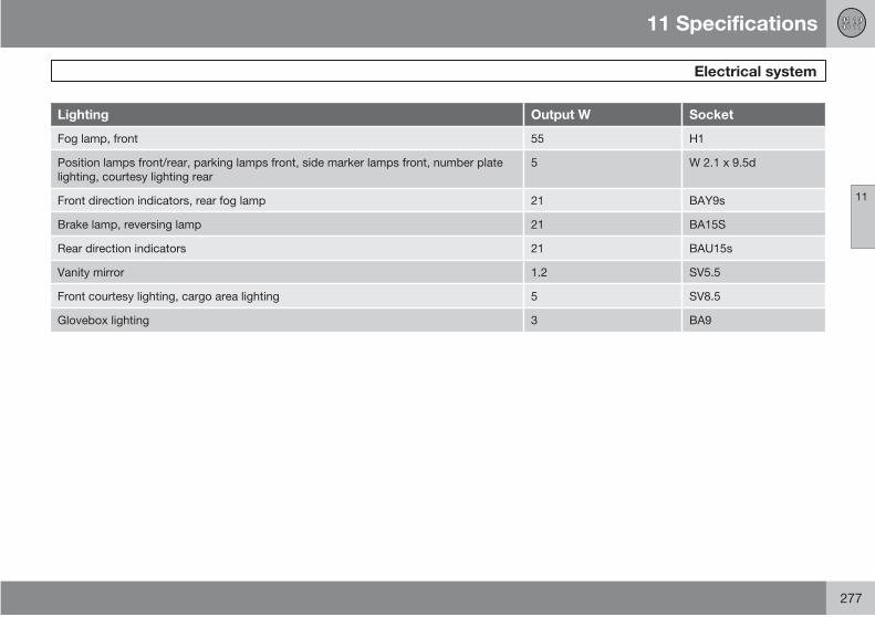
11 Specifications
Electrical system
11
277
Lighting Output W Socket
Fog lamp, front 55 H1
Position lamps front/rear, parking lamps front, side marker lamps front, number plate
lighting, courtesy lighting rear
5 W 2.1 x 9.5d
Front direction indicators, rear fog lamp 21 BAY9s
Brake lamp, reversing lamp 21 BA15S
Rear direction indicators 21 BAU15s
Vanity mirror 1.2 SV5.5
Front courtesy lighting, cargo area lighting 5 SV8.5
Glovebox lighting 3 BA9
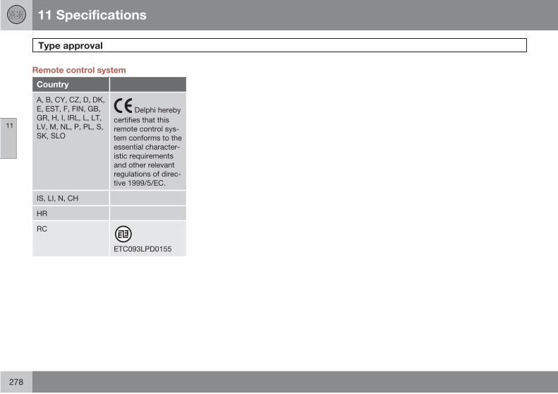
11 Specifications
Type approval
11
278
Remote control system
Country
A, B, CY, CZ, D, DK,
E, EST, F, FIN, GB,
GR, H, I, IRL, L, LT,
LV, M, NL, P, PL, S,
SK, SLO
certifies that this
remote control sys-
tem conforms to the
essential character-
istic requirements
and other relevant
regulations of direc-
tive 1999/5/EC.
IS, LI, N, CH
HR
RC
ETC093LPD0155
Delphi hereby
12 Alphabetical Index
12
279
A
ABS fault.................................................... 48
Active Bi-Xenon Lights...................... 52, 55
Adaptive system...................................... 136
Additional heater........................................ 88
Adjusting headlamp pattern.................... 161
Bi-Xenon headlamp......................... 161
Halogen headlamp............................. 161
Adjusting the steering wheel...................... 64
AF – automatic frequency update........... 240
Airbag
activating/deactivating, PACOS........... 21
driver's and front passenger side......... 19
Air conditioning.......................................... 80
ECC...................................................... 84
rear of passenger compartment........... 51
Air distribution............................................ 81
Air distribution, A/C................................... 85
Air quality system, ECC............................. 84
Air vents
instrument panel................................... 81
Alarm
alarm indicator.................................... 121
alarm signals....................................... 122
arming................................................. 121
automatic alarm activation................. 122
deactivating a triggered alarm............ 122
disarming............................................ 121
general................................................ 121
All-wheel drive, AWD............................... 138
Audio
headphones socket............................ 231
surround............................................. 235
Audio, see also Sound............................. 229
Audio files................................................ 242
Audio system
functions............................................. 233
Audio volume
phone.................................................. 247
Auto, ECC.................................................. 85
Automatic car washes............................. 186
Automatic gearbox.......................... 135, 136
Lock-up function................................ 136
safety systems.................................... 137
towing and recovery........................... 149
trailer................................................... 152
W button............................................. 136
Automatic locking.................................... 116
AUX.......................................................... 233
Auxiliary lamps........................................... 52
Average fuel consumption......................... 57
AWD, All-wheel drive............................... 138
B
Backrest
front seat, lowering............................... 92
Backrest rear seat, lowering.................... 103
Bag holder............................................... 109
Bass speaker........................................... 235
Battery..................................................... 205
maintenance............................... 195, 205
overload.............................................. 127
specifications...................................... 276
start assistance................................... 151
symbols on the battery....................... 205
Blind spot (BLIS)...................................... 145
Blind Spot Information System, BLIS 52, 145
Boarding
rear seat.............................................. 103
Bonnet..................................................... 196
Bonnet, opening...................................... 196
12 Alphabetical Index
12
280
Booster cushion
folding up.............................................. 34
lowering................................................ 35
Booster cushion, integrated...................... 34
Bottle holder for rear seat passengers...... 99
Brakes
Anti-lock braking system, ABS........... 139
Brake system........................................... 139
Bulbs, see Lighting.......................... 207, 276
C
Calls
functions during a call........................ 249
Car care................................................... 186
Car care, leather upholstery.................... 188
Cargo area............................................... 105
bag holder........................................... 109
cargo area compartment.................... 109
cargo cover......................................... 109
electrical socket.................................. 108
Lighting................................................. 96
loading................................................ 106
safety grille.......................................... 107
safety net............................................ 106
Cargo area compartment........................ 109
Cargo cover............................................. 109
Car upholstery......................................... 188
Car wash.................................................. 186
Catalytic converter................................... 275
recovery.............................................. 150
CD
changer............................................... 242
CD functions............................................ 242
Checking and topping up the coolant..... 201
Children..................................................... 30
child safety locks.......................... 51, 119
child seats and airbags......................... 30
child seats and side airbags................. 23
location in the car................................. 30
location in the car, table....................... 31
safety.................................................... 30
Child safety locks...................................... 51
Child seats................................................. 30
extra locking function in seatbelt.......... 36
ISOFIX fixture system for child seats. . . 35
recommended...................................... 31
upper mounting points for child seats.. 35
Cigarette lighter socket.............................. 52
Cleaning
automatic car washes......................... 186
car wash............................................. 186
rims..................................................... 186
seatbelts............................................. 188
upholstery........................................... 188
water-repellent surface......................... 71
Clock, setting............................................. 45
Clutch fluid, checking & topping up........ 202
Coat hanger............................................... 99
Cold start
automatic gearbox.............................. 136
Collision
Inflatable Curtain, IC............................. 25
Colour code, paint................................... 189
Combined instrument panel...................... 45
Compass.................................................... 67
calibration............................................. 70
setting the zone.................................... 67
Condensation.......................................... 198
Condensation in headlamps.................... 186
Cooling system........................................ 126
Cruise control............................................ 61
Cup holder......................................... 99, 100
12 Alphabetical Index
12
281
D
Deadlocks
temporary deactivation....................... 118
temporary deactivation of the alarm
detectors............................................. 122
Defroster.................................................... 86
Detectors................................................... 52
Diesel....................................................... 198
Diesel: engine preheater............................ 49
Diesel particle filter.................................. 130
Direction indicators.................................... 56
Display, messages..................................... 50
Dolby Surround Pro Logic II.................... 228
Door mirrors............................................... 70
Driver's door control panel.................. 44, 65
Driving
cooling system.................................... 126
economical......................................... 126
in water............................................... 127
slippery driving conditions.................. 126
with the tailgate open......................... 126
with trailer........................................... 152
Driving in water........................................ 127
Driving with a trailer
towball load........................................ 266
towing capacity.......................... 152, 266
DSTC, see also Stability control sys-
tem..................................................... 49, 141
operation............................................. 141
E
ECC, electronic climate control........... 80, 84
Economical driving.................................. 126
ECO pressure.......................................... 171
table.................................................... 172
Electrical socket
cargo area........................................... 108
centre console...................................... 52
rear seat................................................ 64
Electrical system...................................... 276
Emergency calls....................................... 246
Emergency equipment
warning triangle.................................. 173
Emergency puncture repair..................... 180
Emission control
fault indicator........................................ 48
Engine compartment............................... 197
Engine oil......................................... 199, 269
adverse driving conditions.................. 269
capacities........................................... 269
changing............................................. 199
filter..................................................... 199
oil grade.............................................. 269
oil pressure........................................... 48
Engine preheater........................................ 49
Engine specifications............................... 268
EON - Enhanced Other Networks............ 241
Equalizer.................................................. 235
Expectant mothers, seatbelt...................... 17
External audio source
AUX-socket......................................... 233
External dimensions................................ 266
F
Fan
ECC...................................................... 86
First aid equipment.................................. 175
Floor mats.................................................. 92
Fluids, capacities..................................... 271
Fluids and oils.................................. 199, 271

12 Alphabetical Index
12
282
Fluids and oils, checks, engine compart-
ment......................................................... 200
Fluids and oils general............................. 195
Fog lamp
front...................................................... 55
Fog lamps
rear........................................................ 55
Front seat
lumbar................................................... 94
massage............................................... 94
Fuel
fuel consumption, display..................... 57
fuel economy...................................... 171
parking heater....................................... 87
refuelling............................................. 128
Fuses....................................................... 214
box in cargo area................................ 222
box in cargo area - Executive............. 224
box in passenger compartment.......... 220
box in the engine compartment.......... 216
changing............................................. 214
end box............................................... 218
general................................................ 214
G
Gearbox
automatic............................................ 135
manual................................................ 134
Glovebox.................................................... 98
Gross vehicle weight............................... 266
H
Hazard warning flashers............................ 53
Headlamp levelling.................................... 54
Headlamp pattern, adjusting................... 161
Headlamps
ABL....................................................... 55
Off/On................................................... 54
Headlamp washers.................................... 60
Headphones socket................................. 231
Head restraint
centre seat, rear.................................. 104
Heating
front seats............................................. 53
rearview and door mirrors.............. 53, 86
rear window.................................... 53, 86
High-pressure headlamp washing............. 60
HomeLink EU.......................................... 74
Home safe lighting
setting................................................... 56
I
Ignition keys............................................. 133
IMEI number............................................ 251
Immobiliser...................................... 114, 133
Inflatable Curtain........................................ 25
Information display.................................... 50
Infotainment system................................ 228
Instrument lighting..................................... 55
Instrument overview
left-hand drive....................................... 40
right-hand drive.................................... 42
Integrated booster cushion........................ 34
Interior lighting........................................... 95
Interior rearview mirror............................... 67
automatic dimming............................... 67
Intermittent wiping..................................... 59
ISOFIX fixture system for child seats......... 35
12 Alphabetical Index
12
283
J
Jack......................................................... 174
K
Kerb weight.............................................. 266
Key........................................................... 114
remote control key.............................. 114
Keypad in the steering wheel............ 61, 230
Kick-down
automatic gearbox.............................. 137
L
Lambda-sond.......................................... 275
Lamps, see Lighting................................ 207
Leather upholstery, washing instructions 188
Lighting.................................................... 207
Active Bi-Xenon Lights, ABL........ 52, 55
automatic lighting, dipped beam.......... 54
automatic lighting, passenger compart-
ment...................................................... 96
bulbs, specifications........................... 276
cargo area............................................. 96
exterior.................................................. 54
headlamp levelling................................ 54
home safe lighting................................ 56
in passenger compartment................... 95
instrument lighting................................ 55
Lighting panel, passenger compart-
ment...................................................... 54
main/dipped beam............................... 54
position/parking lamps......................... 54
reading lamps....................................... 95
rear fog lamp........................................ 55
switching headlamp pattern right/left-
hand traffic, ABL;.......................... 52, 161
Lighting, bulb replacement...................... 207
bulb location front lamp...................... 208
cargo area........................................... 213
courtesy lighting................................. 212
dipped beam halogen......................... 208
direction indicators............................. 209
fog lamp.............................................. 210
front.................................................... 207
Lamp housing, rear............................. 210
main beam.......................................... 208
main beam Active Bi-Xenon............... 209
main beam Bi-Xenon.......................... 208
main beam halogen............................ 208
number plate lighting.......................... 212
parking lamps..................................... 209
position lamps.................................... 209
rear fog lamp...................................... 212
side marker lamps.............................. 209
vanity mirror........................................ 213
Loading
cargo area........................................... 106
general........................................ 105, 160
load capacity...................................... 160
load carriers........................................ 160
roof load............................................. 160
Load on the roof...................................... 160
Locking/unlocking
glovebox............................................. 117
inside.................................................. 117
outside................................................ 116
tailgate................................................ 117
Lubricants................................................ 271
Lubricants, capacities.............................. 271
M
Main and dipped beam
switching............................................... 56
Main beam "flash"..................................... 56
12 Alphabetical Index
12
284
Maintenance............................................ 195
rustproofing........................................ 190
self-maintenance................................ 195
Manual gearbox....................................... 134
towing and recovery........................... 149
Massage
front seat............................................... 94
Master key............................................... 114
Menus
audio system...................................... 230
Menu structure
audio system...................................... 244
phone, menu options.......................... 258
phone, overview................................. 257
Messages in BLIS.................................... 147
Messages in the information display......... 50
Meters in the combined instrument panel
fuel gauge............................................. 45
outside temperature gauge.................. 45
speedometer......................................... 45
tachometer........................................... 45
trip meter.............................................. 45
Misting....................................................... 80
condensation in headlamps............... 186
rear window.......................................... 53
removing with defroster function.......... 86
Mp3 functions.......................................... 242
MY KEY.................................................... 230
N
NEWS.............................................. 237, 240
O
Oil, see also Engine oil....................... 48, 269
One-key dial............................................. 249
Oxyhydrogen gas..................................... 151
P
PACOS....................................................... 21
key switch off........................................ 21
PACOS, switch.......................................... 21
Paintwork
colour code......................................... 189
damage and touch-up........................ 189
Panel vents in the door pillar..................... 82
Parking assistance............................. 52, 143
parking assistance sensors................ 144
Parking brake....................................... 49, 63
Parking heater
battery and fuel..................................... 88
general.................................................. 87
symbols and display messages............ 87
time setting........................................... 88
Parking lamps............................................ 54
Particle filter....................................... 80, 130
Phone
call volume.......................................... 250
controls............................................... 246
ending a call....................................... 248
last dialled numbers........................... 249
making calls........................................ 248
memory............................................... 250
messages........................................... 251
on/off.................................................. 247
one-key dial........................................ 249
phone book......................................... 250
privacy handset.................................. 248
receiving a call.................................... 248
shortcuts............................................. 247
SIM card............................................. 248
traffic safety........................................ 248
volume reduction during phone call. . . 247
12 Alphabetical Index
12
285
Phone book............................................. 250
Phone system.......................................... 245
Pinch protection, sunroof.......................... 73
Polishing.................................................. 187
Position lamps........................................... 54
Power seat................................................. 93
Power steering fluid, checking and topping
up............................................................. 202
Power sunroof........................................... 72
Power windows......................................... 65
blocking................................................ 66
passenger seat..................................... 66
rear seat................................................ 66
PTY – Programme type............................ 238
Puncture, see Tyres......................... 174, 176
R
Radio
alarm................................................... 238
AUTOSTORE...................................... 236
EON.................................................... 241
frequency update................................ 240
NEWS......................................... 237, 240
PTY..................................................... 238
radio settings...................................... 236
radio stations...................................... 236
radio text............................................. 238
regional............................................... 240
storing stations................................... 236
traffic information................................ 238
tuning.................................................. 237
volume control, programme types..... 237
Radio functions........................................ 236
Radio text................................................ 238
Rain sensor................................................ 59
Random, CD and audio files.................... 243
RDS functions.......................................... 237
resetting.............................................. 241
Reading lamps........................................... 95
Rear centre console, removal.................. 103
Rear seat
boarding............................................. 103
Rear seat, lowering.................................. 103
Rearview and door mirrors
compass............................................... 67
door...................................................... 70
electrically retractable........................... 70
heating.................................................. 53
interior................................................... 67
retractable............................................. 51
Rear window, defrosting............................ 53
Recirculation
ECC...................................................... 85
Refrigerant................................................. 80
Refrigerator compartment....................... 102
Refuelling
fuel cap............................................... 130
refuelling............................................. 130
REG - Regional radio programmes......... 240
Relay/fuse box: see Fuses....................... 214
Remote control................................ 114, 231
functions............................................. 114
programmable...................................... 74
replacing the battery........................... 115
Remote control system, type approval.... 278
Retractable power door mirrors (option). . . 51
Rims
cleaning.............................................. 186
RND – Random........................................ 243
Roll-over protection................................... 28
Roof load................................................. 160
ROPS (Roll Over Protection System)......... 28
ROPS (Roll Over Protection System) (Roll-
over protection).......................................... 28

12 Alphabetical Index
12
286
Rustproofing............................................ 190
S
Safety grille.............................................. 107
Safety net................................................. 106
SCAN
radio stations...................................... 237
Seatbelt
pregnancy............................................. 17
Seatbelt reminder...................................... 17
Seatbelts.................................................... 16
seatbelt tensioner................................. 17
Seats
heating.................................................. 53
lowering the front backrest................... 92
lowering the rear backrest.................. 103
manual setting...................................... 92
power seat............................................ 93
Service programme................................. 194
SIM card.................................................. 248
double................................................. 251
SIPS bag – decal....................................... 23
SIPS bags.................................................. 23
Sliding seat.............................................. 103
SMS......................................................... 251
write.................................................... 251
Soot filter........................................... 50, 130
SOOT FILTER FULL................................. 130
Sound
audio settings............................. 229, 234
audio source............................... 229, 233
Spare wheel............................................. 174
Temporary spare................................ 173
Speed dial numbers................................. 249
Spin control............................................. 141
Spin Control............................................. 141
Spin control function............................... 141
SRS AIRBAG.............................................. 19
SRS system............................................... 19
general.................................................. 19
Stability system........................................ 141
deactivating/activating....................... 141
indicator................................................ 49
symbols.............................................. 141
Stains....................................................... 188
Standby mode, phone............................. 247
Start assistance....................................... 151
Starting the engine................................... 132
Steering lock............................................ 132
Steering wheel
cruise control........................................ 61
keypad.......................................... 61, 230
steering wheel adjustment.................... 64
Stone chips and scratches...................... 189
Storage compartment...................... 100, 101
Storage spaces in the passenger compart-
ment........................................................... 97
Storing radio stations............................... 236
Subwoofer............................................... 235
Sunroof...................................................... 72
opening and closing............................. 72
pinch protection.................................... 73
sunscreen............................................. 73
ventilation position................................ 72
Sunscreen, sunroof.................................... 73
Surround.................................................. 235
Switching
main and dipped beam......................... 56
Symbols
indicator symbols................................. 48
stability system................................... 141
warning symbols................................... 47
12 Alphabetical Index
12
287
T
Tailgate
driving with open tailgate................... 126
locking/unlocking................................ 114
open...................................................... 64
Temperature
actual temperature............................... 80
Temperature control.................................. 86
Tools........................................................ 174
Towbar............................................. 152, 156
Towbar, see Towing equipment.............. 154
Towing..................................................... 149
towing eye.......................................... 149
Towing capacity............................... 152, 266
Towing equipment................................... 152
general........................................ 152, 154
installation........................................... 156
removing............................................. 158
specifications...................................... 155
Towing eye............................................... 149
TPMS – Tyre Pressure Monitoring........... 178
TP – Traffic information.................... 238, 240
Traction control system........................... 141
Traffic information............................ 238, 240
Trailer....................................................... 152
cable................................................... 154
driving with a trailer............................ 152
Trip computer............................................ 57
Type approved, remote control system... 278
Type designation..................................... 264
Tyres
direction of rotation............................ 170
driving characteristics......................... 168
general................................................ 168
maintenance....................................... 168
pressure...................................... 171, 172
puncture repair................................... 180
specifications...................................... 168
speed ratings...................................... 168
tread wear indicators.......................... 169
tyre pressure monitoring..................... 178
winter tyres......................................... 170
V
Ventilation fan function.............................. 80
Vibration damper..................................... 154
Volume control......................................... 233
W
Warning lamp
stability and traction control system. . 141
Warning symbol, AIRBAG system............. 18
Warning triangle....................................... 173
Washers
headlamps............................................ 60
rear window.......................................... 60
washer fluid, filling.............................. 200
windscreen........................................... 60
Water and dirt-repellent coating................ 71
Water-repellent surface, cleaning............ 187
Waxing..................................................... 187
Weights
kerb weight......................................... 266
trailer weight....................................... 152
Wheels
changing............................................. 176
installation........................................... 177
removal............................................... 176
snow chains........................................ 169
spare wheel........................................ 174
Whiplash injury........................................... 26
Whiplash injury, WHIPS............................. 26

12 Alphabetical Index
12
288
WHIPS
whiplash injury...................................... 26
Windscreen washing.................................. 60
Windscreen wipers.................................... 59
rain sensor............................................ 59
Winter tyres.............................................. 170
Wiper
rear window.......................................... 60
Wiper blades............................................ 203
cleaning.............................................. 203
replacing, rear window....................... 203
replacing, windscreen......................... 203