owner’s manual inverter/charger - altestore.com series inverter/charger owner’s manual ©june...
TRANSCRIPT

Inverter/ChargerUX Series
Owner’s Manual
Smart choice for power
www.xantrex.com

©2002 Xantrex Technology Inc. All Rights Reserved.P/N 975-0026-01-01 Rev A 06/2002
ii
About Xantrex
Xantrex Technology Inc. develops, manufactures and markets leading advancedpower electronic and control products for the Distributed, Mobile, andProgrammable Power markets. The company’s enabling technology converts rawelectrical power from any central, distributed, or backup power source into high-quality power required by electronic and electrical equipment.
Xantrex products are used for various applications: for renewable and distributedpower solutions such as solar, wind, microturbines and fuel cells; to supplybackup power for homes, small businesses and traffic lights during electric griddisruptions; to provide auxiliary electricity in boats, recreational vehicles, carsand heavy duty trucks; and to develop, test, and power precision equipment suchas semi-conductor manufacturing and medical equipment. The company sells itsproducts under the Xantrex, Trace, Heart and Statpower brands.
TrademarksXantrex is a registered trademark of Xantrex International.
Notice of Copyright
UX Series Inverter/Charger Owner’s Manual ©June 2002 Xantrex Technology Inc.All rights reserved.
Disclaimer
Due to continual improvement through product updates, photographs and/orillustrations used in this manual may not exactly match your unit. XantrexTechnology Inc., reserves the right to update this product without notice orreleasing an updated manual when fit, form, or function are not affected.
Please see Appendix C - Product Information and Warranty for specificwarranty coverage.
Date and Revision
June 2002, Revision A
Part Number975-0026-01-01
Contact InformationWeb: www.xantrex.com
Phone: 888.608.0721
Fax: 360.435.2229

©2002 Xantrex Technology Inc. All Rights Reserved.P/N 975-0026-01-01 Rev A 06/2002
iii
IMPORTANT SAFETY INSTRUCTIONS
This manual contains important safety instructions that should be followedduring the installation and maintenance of this product.
To reduce the risk of electrical shock, and to ensure the safe installation andoperation of this product, the safety symbols shown on this page have beenplaced throughout this manual to indicate dangerous conditions and importantsafety instructions.
• All electrical work must be done in accordance with local, national, and/orinternational electrical codes.
• Before installing or using this device, read all instructions and cautionarymarkings located in the manual, and in (or on) the inverter, the batteries, andthe PV array.
• Do not expose this unit to rain, snow, or liquids of any type. This product isdesigned for indoor mounting only.
• To reduce the chance of short circuits, use insulated tools when installing orworking with the inverter, the batteries, or the PV array .
• Remove ALL jewelry while installing this system. This will greatly reduce thechance of accidental exposure to live circuits.
• The inverter contains more than one live circuit (AC line, batteries and/or PVarray). Power may be present at more than one source.
• This product does not contain any user-serviceable parts. Do not attempt torepair this unit. All repairs should be done by an Authorized Service Center.
• DO NOT install 120 volt AC stand-alone inverters onto 120/240 volt AC multi-branch circuit wiring. This could pose a fire hazard due to an overloaded neutralreturn wire in this configuration.
See Section 5.0, Troubleshooting, pages 59 - 63, for additional information onmulti-branch circuit wiring.
WARNING - ADANGEROUS VOLTAGE ORCONDITION EXISTS IN THISAREA. USE EXTREMECAUTION WHENPERFORMING THESETASKS.
AVERTISSEMENT - UNETENSION OU CONDITIONDANGEREUSE EXISTEDANS CETTE ZONE. FAIREPREUVE D’EXTRÊMEPRUDENCE LORS DE LARÉALISATION DE CESTÂCHES.
NOTE: This statement is important.Follow instructions closely.
NOTE: Cette déclaration estimportante. Suivre lesinstructions de près.
CAUTION - This procedure iscritical to the safe installationor operation of the unit.Follow these instructionsclosely.
ATTENTION - Cette procédureest essentielle à l’installationou l’utilisation de l’unité entoute sécurité. Suivre cesinstructions de près.
SAVE THESE INSTRUCTIONS

©2002 Xantrex Technology Inc. All Rights Reserved.P/N 975-0026-01-01 Rev A 06/2002
iv
BATTERY SAFETY INFORMATION
• Always wear eye protection, such as safety glasses, when working with batteries.
• Remove all jewelry before working with batteries.
• Never work alone. Have someone assist you with the installation or be closeenough to come to your aid when working with batteries.
• Always use proper lifting techniques when handling batteries.
• Always use identical types of batteries.
• Never install old or untested batteries. Check each battery’s date code or labelto ensure age and type.
• Batteries are temperature sensitive. For optimum performance, they should beinstalled in a stable temperature environment.
• Batteries should be installed in a well-vented area to prevent the possiblebuildup of explosive gasses. If the batteries are installed inside an enclosure,vent its highest point to the outdoors.
• When installing batteries, allow at least 1 inch of air space between batteries topromote cooling and ventilation.
• NEVER smoke in the vicinity of a battery or generator.
• Always connect the batteries first, then connect the cables to the inverter. Thiswill greatly reduce the chance of spark in the vicinity of the batteries.
• Use insulated tools when working with batteries.
• When connecting batteries, always verify proper voltage and polarity.
• Do not short-circuit battery cables. Fire or explosion can occur.
• In the event of exposure to battery electrolyte, wash the affected area with soapand water. If acid enters the eyes, flood them with running cold water for atleast 15 minutes and get immediate medical attention.
• Always recycle old batteries. Contact your local recycling center for properdisposal information.
SAVE THESE INSTRUCTIONS

©2002 Xantrex Technology Inc. All Rights Reserved.P/N 975-0026-01-01 Rev A 06/2002
v
TTTTTable of Cable of Cable of Cable of Cable of Contentsontentsontentsontentsontents
1.0 Introduction ............................................................................................................................................................................... 1
Features and Options ......................................................................................................................................................... 2
Standard Features ...................................................................................................................................................... 2
Options ...................................................................................................................................................................... 2
Unpacking and Inspection ................................................................................................................................................. 3
Model Identification and Numbering Conventions ............................................................................................................ 3
2.0 System Configuration ................................................................................................................................................................ 5
Types of Applications ......................................................................................................................................................... 5
Types of Configurations ..................................................................................................................................................... 5
120 Vac/60 Hz Models ............................................................................................................................................... 5
230 Vac/50 Hz Models ............................................................................................................................................... 5
Battery-Bank Requirements ............................................................................................................................................... 5
Pre-Configuration Planning ............................................................................................................................................... 5
Off-Grid Applications ......................................................................................................................................................... 6
Renewable Energy Systems ........................................................................................................................................ 6
Renewable Energy Systems with Optional Generator Backup .................................................................................... 8
Generator-Only Systems ............................................................................................................................................. 10
120 Vac Generators using the SB Option on the Inverter .................................................................................... 10
120 Vac Generators using a Stand-alone Battery Charger .................................................................................. 12
240 Vac/60 Hz Generators .......................................................................................................................................... 14
On-Grid Applications ......................................................................................................................................................... 16
Utility Backup with a Generator ................................................................................................................................. 16
Adding Accessories to the Inverter .................................................................................................................................... 18
Remote Monitoring .................................................................................................................................................... 18
Battery Temperature Sensor ....................................................................................................................................... 19
Generators ......................................................................................................................................................................... 20
Generator Requirements ............................................................................................................................................ 20
3.0 Installation ................................................................................................................................................................................ 21
Pre-Installation .................................................................................................................................................................. 21
Tools Required ............................................................................................................................................................ 21
Hardware/Materials Required .................................................................................................................................... 21
Pre-Installation Planning ................................................................................................................................................... 21
Location Considerations ............................................................................................................................................. 22
Mounting Considerations ........................................................................................................................................... 22
Ventilation Requirements ........................................................................................................................................... 22
Wiring Considerations ................................................................................................................................................ 22
AC Connections .................................................................................................................................................. 23
DC Connections .................................................................................................................................................. 23

©2002 Xantrex Technology Inc. All Rights Reserved.P/N 975-0026-01-01 Rev A 06/2002
vi
TTTTTable of Cable of Cable of Cable of Cable of Contents ontents ontents ontents ontents (continued)
Grounding Considerations .........................................................................................................................................23
AC Grounding .....................................................................................................................................................23
DC Grounding .....................................................................................................................................................23
System Grounding ......................................................................................................................................................24
Equipment or Chassis Grounding ....................................................................................................................... 24
Grounding Electrodes/Ground Rods .................................................................................................................... 25
Bonding the Grounding System .......................................................................................................................... 25
Battery Considerations ......................................................................................................................................................26
Battery Voltage ..........................................................................................................................................................26
Battery Location .........................................................................................................................................................26
Battery Temperature ...................................................................................................................................................26
Battery Pre-Installation .......................................................................................................................................27
Removing the Top Cover of the Inverter ............................................................................................................................ 28
Configuring the Inverter’s Optional Battery Charger ......................................................................................................... 29
Jumper Settings for the Optional Battery Charger ...................................................................................................... 30
Wiring Pre-Installation .......................................................................................................................................................31
Main Service Panel .....................................................................................................................................................31
Sub-Panel ...................................................................................................................................................................31
AC Circuit Breakers ....................................................................................................................................................31
DC Disconnect ............................................................................................................................................................31
Wire Routing ..............................................................................................................................................................31
Inverter Mounting .............................................................................................................................................................32
Wall-Mounting Procedure ..........................................................................................................................................33
DC Wiring ..........................................................................................................................................................................34
Battery Cables ............................................................................................................................................................34
DC Disconnect and Over-current Protection ............................................................................................................... 35
DC Grounding ............................................................................................................................................................36
Battery Installation .....................................................................................................................................................37
Installing the Battery Temperature Sensor (BTS) ........................................................................................................ 38
AC Wiring ..........................................................................................................................................................................39
Sub-panel Mounting ..................................................................................................................................................39
Access to the Inverter’s AC Terminal Block ................................................................................................................. 39
AC Input Wiring to Inverter (only for inverters with the SB Option installed) ............................................................. 42
AC Output Wiring to the Sub-panel .................................................................................................................... 43
AC Input Wiring to the Main Utility Breaker Box ................................................................................................ 44
3.0 Installation (continued)

©2002 Xantrex Technology Inc. All Rights Reserved.P/N 975-0026-01-01 Rev A 06/2002
vii
TTTTTable of Cable of Cable of Cable of Cable of Contentsontentsontentsontentsontents (continued)
Generators ......................................................................................................................................................................... 45
Basic 120 Vac Generator Hookup (Off-Grid applications only) ................................................................................... 45
Basic 120 Vac Utility/Generator Hookup .................................................................................................................... 46
Generator Connections (to AC transfer switch) .................................................................................................. 46
Utility Connections (to AC transfer switch) ......................................................................................................... 46
Inverter Connections (to AC transfer switch) ...................................................................................................... 46
Sub-panel Connections .............................................................................................................................................. 46
Remote Monitoring .................................................................................................................................................... 48
4.0 Operation .................................................................................................................................................................................. 49
Control Panel ..................................................................................................................................................................... 49
Power ON/OFF Button ................................................................................................................................................ 50
Green Status LED ....................................................................................................................................................... 50
Yellow Charger Status LED ......................................................................................................................................... 50
Search Sense Mode ........................................................................................................................................................... 50
Search Sense Operation ............................................................................................................................................. 50
Benefits of Using Search Sense .................................................................................................................................. 51
Setting Up Search Mode ............................................................................................................................................ 51
Standby (SB) Option .......................................................................................................................................................... 52
SB Option Operation .................................................................................................................................................. 52
Transfer Switching Speed ........................................................................................................................................... 52
Battery Charger LED Indicator .................................................................................................................................... 53
5.0 Troubleshooting ......................................................................................................................................................................... 55
Potential Problem Loads for the Inverter ........................................................................................................................... 56
Ceiling Fans ................................................................................................................................................................ 56
Cell Phones ................................................................................................................................................................ 56
Computers and Sensitive Electronics .......................................................................................................................... 56
Consumer Electronics ................................................................................................................................................. 56
Clocks ........................................................................................................................................................................ 56
Decreasing Loads ....................................................................................................................................................... 56
Dimmer Switches ....................................................................................................................................................... 57
Fluorescent Lights ...................................................................................................................................................... 57
Heavy Loads ............................................................................................................................................................... 57
Microwave Ovens ....................................................................................................................................................... 57
Printers ....................................................................................................................................................................... 57
Rechargeable Devices ................................................................................................................................................ 57
Undersized Loads ....................................................................................................................................................... 57
3.0 Installation (continued)
©2002 Xantrex Technology Inc. All Rights Reserved.P/N 975-0026-01-01 Rev A 06/2002
viii
Potential Problem Loads related to Search Sense Mode .................................................................................................... 58
Confirming Search Mode Operation ........................................................................................................................... 58
Incandescent Lights ............................................................................................................................................58
Fluorescent Bulbs ...............................................................................................................................................58
Other loads .........................................................................................................................................................58
Multiwire Branch Circuits ..................................................................................................................................................59
Identifying Multiwire Branch Circuits ......................................................................................................................... 62
Correcting Multiwire Branch Circuit Wiring ................................................................................................................ 63
Appendix A - Specifications ..............................................................................................................................................................A-1
Appendix B - Batteries ......................................................................................................................................................................B-1
Selection of a Battery Type ................................................................................................................................................B-1
Flooded Lead Acid (FLA) .............................................................................................................................................B-1
RV and Marine ....................................................................................................................................................B-1
Golf Cart .............................................................................................................................................................B-1
Industrial (electric forklift) ..................................................................................................................................B-1
Sealed Batteries (GEL and AGM) ................................................................................................................................B-2
Gel Cell ...............................................................................................................................................................B-2
Absorbed Glass Mat ...........................................................................................................................................B-2
NiCad and NiFe Batteries ...........................................................................................................................................B-2
Battery-Bank Sizing ...........................................................................................................................................................B-3
Estimating Battery Requirements ............................................................................................................................... B-3
Typical Appliance Wattages ........................................................................................................................................B-7
Battery Cable Sizing ..........................................................................................................................................................B-8
Battery Configurations ......................................................................................................................................................B-9
Series .........................................................................................................................................................................B-9
Parallel .......................................................................................................................................................................B-9
Series-Parallel .............................................................................................................................................................B-9
Wiring Batteries in Series ....................................................................................................................................B-10
Wiring Batteries in Parallel .................................................................................................................................B-12
Wiring Batteries in Series-Parallel ....................................................................................................................... B-13
TTTTTable of Cable of Cable of Cable of Cable of Contents ontents ontents ontents ontents (continued)
5.0 Troubleshooting (continued)

©2002 Xantrex Technology Inc. All Rights Reserved.P/N 975-0026-01-01 Rev A 06/2002
ix
Battery Care and Maintenance ..........................................................................................................................................B-16
Charge Rate ...............................................................................................................................................................B-16
Bulk Voltage ...............................................................................................................................................................B-16
Float Voltage ..............................................................................................................................................................B-16
Temperature Compensation .......................................................................................................................................B-16
Equalization Charging ................................................................................................................................................B-16
Replenish Water Levels ...............................................................................................................................................B-17
Clean Battery Cables and Posts ..................................................................................................................................B-17
Torque Battery Connections .......................................................................................................................................B-17
Check Battery’s State-of-Charge ................................................................................................................................B-18
Appendix C - Product Information and Warranty ..............................................................................................................................C-1
Limited Warranty ...............................................................................................................................................................C-1
What does this warranty cover and how long does it last? ........................................................................................C-1
What will Xantrex do? ...............................................................................................................................................C-1
How do you get service? ............................................................................................................................................C-2
What does this warranty not cover? ..........................................................................................................................C-2
DISCLAIMER ......................................................................................................................................................................C-3
Product ......................................................................................................................................................................C-3
Exclusions ..................................................................................................................................................................C-3
Information ................................................................................................................................................................C-3
WARNING: LIMITATIONS ON USE ..............................................................................................................................C-4
Return Material Authorization Policy .................................................................................................................................C-5
Shipping Instructions ..................................................................................................................................................C-5
If you are returning a product from outside of the USA or Canada ............................................................................C-5
If you are returning a product to a Xantrex Authorized Service Center (ASC) ............................................................ C-5
Service Information ............................................................................................................................................................C-6
Appendix D - Index ...........................................................................................................................................................................D-1
TTTTTable of Cable of Cable of Cable of Cable of Contentsontentsontentsontentsontents (continued)
Appendix B - Batteries (continued)

©2002 Xantrex Technology Inc. All Rights Reserved.P/N 975-0026-01-01 Rev A 06/2002
x
List of FiguresList of FiguresList of FiguresList of FiguresList of Figures
Figure 1-1 - UX Series Inverter/Charger ............................................................................................................................. 1
Figure 1-2 - Inverter/Charger Model Identification ............................................................................................................ 4
Figure 2-1 - Off-Grid Application, Renewable Energy System (with SB Option on the UX Inverter) ................................... 7
Figure 2-2 - Off-Grid Application, Renewable Energy System (without SB Option on the UX Inverter) .............................. 9
Figure 2-3 - Off-Grid Application, 120 Vac Generator-only System (with SB Option on the UX Inverter) ........................... 11
Figure 2-4 - Off-Grid Application, 120 Vac Generator-only System (without SB Option on the UX Inverter) ...................... 13
Figure 2-5 - Off-Grid Application, 240 Vac Generator-only System .................................................................................... 15
Figure 2-6 - On-Grid Application, Utility Backup with a Generator (with SB Option on the UX Inverter) ........................... 17
Figure 2-7 - RC8 Remote Control .......................................................................................................................................18
Figure 2-8 - Battery Temperature Sensor ........................................................................................................................... 19
Figure 3-1 - Removing the Cover from the Inverter ........................................................................................................... 28
Figure 3-2 - Location of the Optional Battery Charger Configuration Jumpers .................................................................. 29
Figure 3-2a - Jumper Enlargement .....................................................................................................................................29
Figure 3-2b - Jumper Placement ........................................................................................................................................29
Figure 3-3 - Battery Charger Jumper Settings .................................................................................................................... 30
Figure 3-4 - Wall-Mounting Method ..................................................................................................................................32
Figure 3-5 - Dimensional Drawing for Screw Hole Placement ............................................................................................ 33
Figure 3-6 - DC Grounding .................................................................................................................................................35
Figure 3-7 - Battery Cable Connections ............................................................................................................................. 34
Figure 3-8 - BTS (RJ11) Port Location .................................................................................................................................36
Figure 3-9 - BTS Installed on Battery .................................................................................................................................36
Figure 3-10 - AC Access Covers and Hardware .................................................................................................................. 37
Figure 3-11 - AC Input Wiring (only for inverters with the SB Option installed) ................................................................. 40
Figure 3-12 - AC Output Wiring .........................................................................................................................................41
Figure 3-13 - Utility Breaker Box Wiring Diagram .............................................................................................................. 42
Figure 3-14 - Basic 120 Vac Generator Block Diagram (for Off-Grid applications) ............................................................. 43
Figure 3-15 - Basic 120 Vac Utility/Generator Block Diagram ............................................................................................ 45
Figure 3-16 - Remote Monitor Port Location ..................................................................................................................... 46
Figure 4-1 - Control Panel ..................................................................................................................................................47
Figure 4-2 - Battery Charger Status LED ............................................................................................................................ 51

©2002 Xantrex Technology Inc. All Rights Reserved.P/N 975-0026-01-01 Rev A 06/2002
xi
Figure 5-1 - Conventional “Home-run” Type Wiring .......................................................................................................... 59
Figure 5-2 - Multiwire Branch Circuit Wiring and Current Flow ......................................................................................... 60
Figure 5-3 - 120 Vac Inverter Incorrectly Wired in a Multiwire Branch Circuit .................................................................... 61
Figure 5-4 - Multiwire Branch Circuit Wire ......................................................................................................................... 62
Figure 5-5 - Using a T240 Autotransformer in Multiwire Branch Circuit Wiring ................................................................. 63
Figure B-1 - AWG Wire Size Reference Chart ..................................................................................................................... B-8
Figure B-2 - 6-volt/100 Ah Battery Wiring - Series Configuration ....................................................................................... B-10
Figure B-3 - 2-volt/100 Ah Battery Wiring - Series Configuration ....................................................................................... B-11
Figure B-4 - 12-volt/200 Ah Battery Wiring - Parallel Configuration ................................................................................... B-12
Figure B-5 - Step 1 - Wiring Batteries in Series .................................................................................................................. B-13
Figure B-6 - Step 2 - Two Series Strings Wired in Parallel ................................................................................................... B-14
Figure B-7 - Step 3 - Series-Parallel Configuration Wired to the Inverter ........................................................................... B-15
List of Figures (continued)List of Figures (continued)List of Figures (continued)List of Figures (continued)List of Figures (continued)

©2002 Xantrex Technology Inc. All Rights Reserved.P/N 975-0026-01-01 Rev A 06/2002
xii
List of TList of TList of TList of TList of Tablesablesablesablesables
Table 1-1 - Output Parameters by Model Suffix Code ........................................................................................................ 4
Table 3-1 - Safety Ground Wire Size ..................................................................................................................................24
Table 3-2 - Minimum Recommended Battery Cable Size Vs. Length .................................................................................. 34
Table 3-3 - Battery Cable to Maximum Breaker/Fuse Size ................................................................................................. 35
Table 3-4 - AC Current Requirements (Input and Output) .................................................................................................. 38
Table 3-5 - Minimum Recommended AC Wire Size (Input and Output) .............................................................................. 39
Table 5-1 - Troubleshooting the UX Model Inverter/Charger .............................................................................................. 53
Table B-1 - Estimating Battery Requirements - Sample ...................................................................................................... B-4
Table B-2 - Estimating Battery Requirements - Worksheet ................................................................................................. B-6
Table B-3 - Typical Appliance Wattage ............................................................................................................................... B-7
Table B-4 - Battery State-of-Charge ...................................................................................................................................B-18

©2002 Xantrex Technology Inc. All Rights Reserved.P/N 975-0026-01-01 Rev A 06/2002
1
1.0 Introduction
Thank you for purchasing the UX Series inverter/charger from XantrexTechnology Inc. The UX inverter takes DC energy stored in a battery-bank andconverts it to usable AC power. The UX inverter/charger features an AC pass-through circuit, powering home appliances from utility or generator power whilecharging the batteries with its optional battery charger. When utility power fails,the battery backup system keeps your appliances powered until utility power isrestored.
Internal protection circuits in the inverter prevent over-discharge of the batteriesby shutting down the inverter when low-battery conditions occur. When utilityor generator power is restored, the inverters with the battery charger optioninstalled transfers to the AC source and recharges the batteries.
The front panel features LEDs for reading system status and controls tocustomize the inverter settings for your battery-bank.
Figure 1-1UX Series Inverter/Charger

©2002 Xantrex Technology Inc. All Rights Reserved.P/N 975-0026-01-01 Rev A 06/2002
2
1.0 Introduction
Features and Options
The UX Series inverter is an economical product designed to provide a reliablesupply of electricity to all the essential circuits of a home or business. Criticalloads can be powered for hours or days, depending on the size of the systembattery-bank. When connected to the utility grid, the optional battery chargerquickly recharges the batteries.
Standard Features• Modified Sine Wave Power
The UX Series inverters provide a modified sinewave output which operatesmost AC appliances and equipment.
• Simplicity
The UX Series is simple to operate. All inverter and optional battery chargercontrols are located on the AC end panel.
• High Efficiency
The inverter operates at over 90% efficiency through most of its power range.
• Low Power Consumption
UX Series inverters use extremely low current while in the search mode,consuming little more than one watt of power. In the ON mode, the inverter usesless than 8 watts of power.
OptionsThe following options are available for the UX Series inverter:
• SB Option (Battery Charger/AC Transfer Relay)
The inverter can be equipped with a three-stage battery charger designed torecharge typical, deep-cycle batteries.
The built-in, AC transfer relay automatically transfers power from the utility tothe inverter and handles 30 amps of current at 120 Vac (15 amps of current at230 Vac).
• RC8/50
The RC8 allows the inverter to be switched ON or OFF remotely and includes anLED status indicator.
• Battery Temperature Sensor
The battery temperature sensor (BTS) ensures proper charging of the batteriesbased on temperature. Installing a BTS extends battery life by preventingovercharging in warm temperatures and undercharging in cold temperatures.
RC8 Remote Control
Battery Temperature Sensor

©2002 Xantrex Technology Inc. All Rights Reserved.P/N 975-0026-01-01 Rev A 06/2002
3
1.0 Introduction
Unpacking and Inspection
• Carefully unpack the inverter from its shipping carton.
• Verify all of the items listed on the packing material sheet are present. If anyitems are missing, please contact Xantrex Customer Service at 360.435.8826.
• Save your proof-of-purchase. This is required if the unit should requirewarranty service.
• Save the original shipping carton and packing materials! If the inverter everneeds to be returned for service, it should be shipped in the original carton.This is also a good way to protect the inverter if it ever needs to be moved.
• Record the unit’s model, serial number and date of purchase in theappropriate fields on page C-6 in Appendix C, Product Information andWarranty.
Model Identification and Numbering Conventions
The UX Series inverter is identified by the model/serial number label locatednext to the AC access cover. All the necessary information is provided on thelabel such as AC output voltage, power, and frequency (punch holes).
The inverter also has a letter designator followed by 3 or 4 digits (depending onthe version). The model number describes the type of inverter, the outputspecifications, the required battery voltage and the output voltage andfrequency.
“UX” indicates the type of inverter - UX Series.
“11” the first two digits of the numerical designator indicate the inverter’soutput power (in hundreds of watts) - 1100 Watts.
“12” the second two digits indicate the required nominal battery bank voltage -12 Vdc.
“E” the letter suffix code indicates the export output voltage and frequency ofthe inverter - 230 Vac/50 Hz. No letter indicates 120 Vac/60 Hz.
See Table 1-1, Output Parameters by Model Suffix Code on page 4.
“SB” indicates the inclusion of an optional, built-in, three-stage, standbybattery charger.
Example: UX 1112 E, SB
Product Family
Output Power
Country Code (No letter = 120 Vac/60 Hz)
Battery VoltageOptional Standby Battery Charger
NOTE: The unit weighs 25-40 lb/11.4–18.2 kg (dependingon model). Have additionalhelp available if necessary,to assist in lifting the unitduring installation.

©2002 Xantrex Technology Inc. All Rights Reserved.P/N 975-0026-01-01 Rev A 06/2002
4
1.0 Introduction
Figure 1-2Inverter/Charger Model Identification
xiffuSretteL egatloVtuptuO ycneuqerFtuptuO
)retteloN( CAV021 zH06
E CAV032 zH05
Table 1-1Output Parameters by Model Suffix Code
Inverter modelidentification label
Model Identification and Numbering Conventions (continued)

©2002 Xantrex Technology Inc. All Rights Reserved.P/N 975-0026-01-01 Rev A 06/2002
5
2.0 System Configuration
Types of Applications
The UX Series inverter/charger can be configured for a wide variety ofapplications.
• It can be configured for OFF-GRID (stand-alone) applications where no utilitypower is available.
• It can be configured for ON-GRID applications where it can operate the AC loadswhen the utility grid fails, and/or keep the batteries charged.
Types of Configurations
The UX series inverter is designed for either 120 Vac/60 Hz or 230 Vac/50 Hzapplications. In locations where there is a 230 Vac/50 Hz requirement, “E” modelsare available.
120 Vac/60 Hz ModelsThese models produce 120 volts between HOT and NEUTRAL which is standardfor North America.
230 Vac/50 Hz ModelsThese models produce 230 volts between HOT (Line) and NEUTRAL which isstandard for most locations except North America.
Battery-Bank RequirementsThe inverter system can only support loads for the duration of their battery-bankcapacity. Battery-bank pre-planning is essential.
See Appendix B, Batteries, for additional information on battery types andestimating battery-bank sizing.
Pre-Configuration PlanningComprehensive pre-planning is recommended before installing the system toensure all factors are accounted for.
Pre-planning should include (but is not limited to) the following.
1. What are the total watts required for all anticipated loads?
2. What are the voltage requirements for the anticipated loads?(120 Vac or 230 Vac)
3. Battery-bank type, size, and configuration?
4. Are there any local or national electrical codes that need to be met?
5. Are there any special permits required for this installation?
NOTE: It is not possible to use an “E”model inverter to power120/240 Vac/60 Hz loads.

©2002 Xantrex Technology Inc. All Rights Reserved.P/N 975-0026-01-01 Rev A 06/2002
6
2.0 System Configuration
Off-Grid Applications
The UX inverter can be used to support off-grid, stand-alone systems where noutility power is available. Using the UX inverter in an off-grid applicationinclude:
• renewable energy systems (without the SB Option on the inverter),
• renewable energy systems with generator backup (with the SB Option on theinverter), and
• generator-only systems (with and without the SB Option on the inverter).
Renewable Energy Systems
In this configuration, the main power is generated by renewable energy sources,such as solar, wind, or hydro-generators and is stored directly in a battery-bank.The UX inverter will invert the DC power stored in the battery-bank into ACpower to operate the AC loads. The SB Option is not required for thisapplication.
See Figure 2-1 for an illustration of a renewable energy application withoutthe SB Option installed on the UX Inverter.
This illustration includes the optional accessories such as remote monitoringoptions and a variety of renewable energy sources. Disregard any part of thisillustration that does not apply to the system configuration being installed.

©2002 Xantrex Technology Inc. All Rights Reserved.P/N 975-0026-01-01 Rev A 06/2002
7
2.0 System Configuration
Figure 2-1Off-Grid Application
Renewable Energy System (without SB Option on the UX inverter)
Off-Grid Applications (continued)

©2002 Xantrex Technology Inc. All Rights Reserved.P/N 975-0026-01-01 Rev A 06/2002
8
2.0 System Configuration
Renewable Energy Systems with Optional Generator Backup
In the event that renewable energy sources are insufficient to power the requiredloads or keep the batteries charged, a generator can be used to supplement thesystem. The SB Option is required on the inverter for this application. The SBOption provides a pass-through relay that allows power from the generator topass through the inverter to either support the AC loads and/or charge thebatteries.
See Figure 2-2 for an illustration of a renewable energy application with theSB Option installed on the UX Inverter.
This illustration includes the optional generator backup as well as illustratesthe utilization of the optional accessories such as remote monitoring optionsand a variety of renewable energy sources. Disregard any part of thisillustration that does not apply to the system configuration being installed.
See page 20 for additional information regarding generator configurations.
Off-Grid Applications (continued)

©2002 Xantrex Technology Inc. All Rights Reserved.P/N 975-0026-01-01 Rev A 06/2002
9
2.0 System Configuration
Figure 2-2Off-Grid Application
Renewable Energy System (with SB Option on the UX inverter)
Off-Grid Applications (continued)

©2002 Xantrex Technology Inc. All Rights Reserved.P/N 975-0026-01-01 Rev A 06/2002
10
2.0 System Configuration
Off-Grid Applications (continued)
Generator-Only Systems
120 Vac Generators using the SB Option on the Inverter
In this configuration, the generator serves as the main AC source when batteriesare insufficient to power the loads and provides a source of power for theoptional UX battery charger.
See Figure 2-3 for an illustration of a 120 Vac Generator-Only System with theSB Option installed on the UX Inverter.
This illustration includes the optional accessories such as the RC8 RemoteControl and the Battery Temperature Sensor. Disregard any part of thisillustration that does not apply to the system configuration being installed.
See page 20 for additional information regarding generator configurations.

©2002 Xantrex Technology Inc. All Rights Reserved.P/N 975-0026-01-01 Rev A 06/2002
11
2.0 System Configuration
Figure 2-3Off-Grid Application
120 Vac Generator-Only System (with SB Option on UX Inverter)
Off-Grid Applications (continued)

©2002 Xantrex Technology Inc. All Rights Reserved.P/N 975-0026-01-01 Rev A 06/2002
12
2.0 System Configuration
Off-Grid Applications (continued)
Generator-Only Systems (continued)
120 Vac Generators using a Stand-alone Battery Charger
In this configuration, the generator serves as the main AC source when batteriesare insufficient to power the loads. The batteries are charged by a stand-alonebattery charger (e.g., TC20).
See Figure 2-4 for an illustration of a 120 Vac Generator-Only System withoutthe SB Option installed on the UX Inverter.
This illustration includes the optional accessories such as the RC8 RemoteControl and the Battery Temperature Sensor. Disregard any part of thisillustration that does not apply to the system configuration being installed.
See page 20 for additional information regarding generator configurations.

©2002 Xantrex Technology Inc. All Rights Reserved.P/N 975-0026-01-01 Rev A 06/2002
13
2.0 System Configuration
Figure 2-4Off-Grid Application
120 Vac Generator-Only System (without SB Option on UX Inverter)
Off-Grid Applications (continued)
Generator-Only Systems (continued)
©2002 Xantrex Technology Inc. All Rights Reserved.P/N 975-0026-01-01 Rev A 06/2002
14
2.0 System Configuration
Off-Grid Applications (continued)
240 Vac/60 Hz Generators
If using a 120 Vac/60 Hz configuration with the optional battery charger, using a240 Vac/60 Hz generator can optimize battery charging efficiency.
If using a 240 Vac input source (generator) with a 120 Vac/60 Hz inverter, a T240Autotransformer must be installed preceeding the inverter’s input to step downthe voltage to 120 Vac.
See Figure 2-5 for an illustration of a 240 Vac generator system using a120 Vac/60 Hz inverter.
CAUTION: Do not use a240 Vac input source in a120 Vac/60 Hz invertersystem without installingthe T240 Autotransformer.Damage to the inverter canoccur and is not coveredunder warranty.

©2002 Xantrex Technology Inc. All Rights Reserved.P/N 975-0026-01-01 Rev A 06/2002
15
2.0 System Configuration
Figure 2-5Off-Grid Application
240 Vac Generator-Only System
Off-Grid Applications (continued)

©2002 Xantrex Technology Inc. All Rights Reserved.P/N 975-0026-01-01 Rev A 06/2002
16
2.0 System Configuration
On-Grid Applications
Utility Backup with a Generator
The UX inverter can be used with an AC Transfer switch to allow a generator toprovide backup power in the event that the utility grid fails. When the utility gridfails, the inverter switches the loads over to the battery-bank. If the utility failureis prolonged and the batteries become discharged, the generator must be startedto support the loads and recharge the batteries.
See Figure 2-6 for an illustration of a basic utility backup configuration.
This illustration includes the optional accessories such as the RC8 RemoteControl and the Battery Temperature Sensor. Disregard any part of thisillustration that does not apply to the system configuration being installed.

©2002 Xantrex Technology Inc. All Rights Reserved.P/N 975-0026-01-01 Rev A 06/2002
17
2.0 System Configuration
Figure 2-6On-Grid Application
Utility Backup with a Generator (with the SB Option on the UX Inverter)
On-Grid Applications (continued)

©2002 Xantrex Technology Inc. All Rights Reserved.P/N 975-0026-01-01 Rev A 06/2002
18
2.0 System Configuration
Adding Accessories to the Inverter
Remote Monitoring
The UX inverter/charger can be configured with a remote monitor if desired.Remote monitoring can be accomplished by using the optional RC8 RemoteControl accessory.
See page 48 for the location of the port for connecting the RC8 Remote Controlto the inverter.
See the installation guide for the RC8 Remote Control for specific installationinstructions.
Figure 2-7RC8 Remote Control

©2002 Xantrex Technology Inc. All Rights Reserved.P/N 975-0026-01-01 Rev A 06/2002
19
2.0 System Configuration
Adding Accessories to the Inverter (continued)
Battery Temperature Sensor
When the SP Option is installed on the UX inverter, a battery temperature sensor(BTS) can be used. The BTS ensures proper charging of the batteries based ontemperature. Installing a BTS extends battery life by preventing overcharging inwarm temperatures and undercharging in cold temperatures.
See page 38 for the location of the port for connecting the Battery TemperatureSensor to the inverter.
See the installation guide for the Battery Temperature Sensor for specificinstallation instructions.
Figure 2-8Battery Temperature Sensor

©2002 Xantrex Technology Inc. All Rights Reserved.P/N 975-0026-01-01 Rev A 06/2002
20
2.0 System Configuration
Generators
An AC generator can be used with this inverter/charger: 1) as a replacement orsubstitute for utility power; 2) to power loads when utility power is not available(utility outage); and 3) to charge batteries.
The generator must be of the permanently installed type and not a portable unitused for emergency power. Small emergency generators may not have a stableenough voltage or frequency output for the inverter to synchronize to, or provideenough current to fully charge the batteries.
Generator Requirements
The maximum charge rate the battery charger can deliver is dependant upon thepeak AC voltage available. Since the battery charger uses only the top portion ofthe input sine wave, small variations in peak voltage result in large variations inthe amount of energy to the charger. The charger’s rated output is based on autility voltage of 120 Vac
ms which has a peak voltage of 169 Vac
p (230 Vac
ms has a
peak voltage of 325 Vacp).
Low power generators may not produce enough voltage under heavy loadconditions to fully charge the batteries as the voltage peaks may be clipped,limiting the maximum charge rate. Size the generator appropriately for thesystem, including battery charge and load current.
Because generator hookups can vary widely, only basic hookup information isgiven. Complex hookups, involving both the utility and generator, requireadditional hardware such as a manual AC transfer switch and possibly anautotransformer for load balancing.
See pages 45-47 for basic generator wiring to the inverter.
NOTE: Using an AC generator topower loads when utilitypower is not available requiresadditional hardware. Pleaseconsult the owner’s guide foryour generator for additionalinformation.
©2002 Xantrex Technology Inc. All Rights Reserved.P/N 975-0026-01-01 Rev A 06/2002
21
3.0 Installation
Pre-Installation
Finding people qualified to perform installations is sometimes difficult. Xantrexhas made the process easier by developing a certification program for dealerswho install Xantrex renewable energy products.
Xantrex Certified Dealers have completed an extensive technical certificationexamination and are committed to providing excellence in systems design,installation, and service to homeowners and businesses interested in purchasinga renewable energy system.
Contact a Xantrex Certified Dealer for site analysis, system design, andinstallation. For more information, see the Xantrex Web Site atwww.xantrexredealer.com.
Tools RequiredThe following tools may be needed during this installation.
• #2 Phillips screwdriver • Multimeter (True rms) • Level
• Slotted screwdriver • Wire strippers • Pencil
• Assorted open-end wrenches • Torque wrench • Utility knife
• Socket wrench and fittings • Hole saw • Electrical tapeHardware/Materials Required
The following materials may be needed during this installation.
• 4 ft x 4 ft sheet of ½" plywood or 2 x 4 studding (optional depending onmounting method selected)
• Conduit and appropriate fittings
• #12 wood screws (or ½" by 1¼" lag bolts)
• Wire nuts
Pre-Installation PlanningPre-installation planning is recommended before installing the system to ensureall factors are accounted for.
Pre-planning should include (but is not limited to) the following.
1. Battery-bank location?
2. Location of all the components in relation to each other and wire routes?
3. Are renewable energy generators (if used) in a location best suited for it’srespective energy source requirements (i.e., are PV arrays positioned inmaximum sun light?)
4. Is the system design compliant with local or national electrical codes?
NOTE: Before installing the inverter,read all instructions andcautionary markings locatedin this manual.
NOTE: Installations should beperformed by a qualifiedperson or a licensedelectrician following all localand NEC codes.

©2002 Xantrex Technology Inc. All Rights Reserved.P/N 975-0026-01-01 Rev A 06/2002
22
3.0 Installation
Pre-Installation Planning (continued)
Location Considerations
• Inverters contain sophisticated electronic components and should be located ina well-protected, dry environment away from sources of fluctuating or extremetemperatures and moisture. Exposure to saltwater is particularly destructive andpotentially hazardous.
• Locate the inverter as close to the batteries as possible in order to keep thebattery cable length short. However, do not locate the inverter above thebatteries or in the same compartment with vented batteries. Batteries generatehydrogen sulfide gas which is corrosive to electronic equipment. They alsogenerate hydrogen and oxygen. If accumulated, an arc caused by connecting thebattery cables or switching a relay could ignite this mixture. Mounting theinverter in a ventilated enclosure with sealed batteries is acceptable.
Mounting Considerations• The mounting surface must be capable of supporting twice the weight of the
inverter.
• Mount the inverter either on a vertical surface (e.g., wall) or a horizontal surface(e.g., shelf ).
• Use 0.25 inch (0.635 cm) lag bolts for mounting, if necessary.
Ventilation Requirements• Install the inverter in a well-ventilated area/enclosure for proper operation. The
inverter’s thermal shutdown point will be reached sooner than normal in apoorly ventilated environment, resulting in reduced peak-power output andsurge capability, as well as shorter inverter life.
• Some models have an internal fan. Ensure that the air vents and intakes are notobstructed in any way. Provide a minimum clearance of 1½ inches (3.81 cm)around the top and sides of the inverter for ventilation.
Wiring Considerations• All wiring and installation methods should conform to applicable electrical and
building codes.
• Pre-plan the wire and conduit runs. The AC circuits accept cable sizes up to#10 AWG. The DC circuits accept cable sizes up to #4/0 AWG.
• For maximum safety, run both AC and DC cables in conduits.
CAUTION: The inverter/charger can weigh up to40 lb. (18.2 kg) dependingupon configuration.Always use proper liftingtechniques duringinstallation to preventpersonal injury.

©2002 Xantrex Technology Inc. All Rights Reserved.P/N 975-0026-01-01 Rev A 06/2002
23
3.0 Installation
Pre-Installation Planning (continued)
AC ConnectionsSee Table 3-3 on page 41 for the minimum recommended wire sizes for ACconnections.
• Inverter Bypass Switch
This simple item, if installed, could save hours of downtime. If it becomesnecessary to disconnect the inverter or service the batteries, an inverter bypassswitch allows another AC source, such as a generator or the utility power, to beused to directly power the AC loads without rewiring. This item is placedbetween the inverter, the generator (or utility power) and the load center andwould be used with inverters that have the SB option installed.
• AC Transfer Switch
UX Units with the SB Option installed - If more than one AC source is available,this transfer switch would be used to switch from one source to the other. Forexample: If you have a utility power outage and the batteries require charging,you can switch over to your generator and use it to power the load center andcharge the batteries.
See Figure 2-6 on page 17 for an illustration of using the AC transfer switchwith two AC input sources.
UX Units without the SB Option installed - You can use an AC transfer switch toconnect an inverter and an AC generator to the same house wiring. When thegenerator is not running, the inverter is connected to the house wiring. Whenyou turn on the generator, you can use the AC transfer switch to power thehouse wiring from the generator.
See Figure 2-4 on page 13 for an illustration of using the AC transfer switch toconnect the inverter and an AC generator to the same house wiring.
DC Connections
• Battery to inverter cabling should be only as long as required. For example, if#4/0 AWG cables are used, do not exceed 10 feet (one way). For optimalperformance, use pre-assembled battery cables designed specifically for thisapplication (available from Xantrex).
See Table 3-2 on page 34 for the minimum recommended cable sizes.
Grounding Considerations
AC Grounding• The inverter should be connected to a grounded, permanent wiring system.
Neutral and ground conductors should only be bonded at the main utilityservice panel.
DC Grounding• The negative battery conductor should be bonded to the grounding system at
only one point in the system. The size of the conductor is usually based on thesize of the largest conductor (or battery disconnect) in the DC system.
See Table 3-1, Safety Ground Wire Size, on page 24 of this manual, forNEC 250-95 requirements for sizing the ground conductor.

©2002 Xantrex Technology Inc. All Rights Reserved.P/N 975-0026-01-01 Rev A 06/2002
24
3.0 Installation
Pre-Installation Planning (continued)
System Grounding
The inverter/charger should be connected to a grounded, permanentwiring system. For most installations, the negative battery conductorshould be bonded to the grounding system at one point in the system.
The grounding requirements vary by country and application. Allinstallations must comply with national and local codes and ordinances.Consult local codes and the NEC for specific requirements.
Table 3-1 provides minimum required ground wire sizes per NEC Code.
NOTE: Be sure to consult your localand national electrical codesto confirm grounding andbonding requirements foryour specific system.
eziStcennocsiDCDyrettaB eriWdnuorGreppoCfoeziSmiminiM
pma06ropma03 GWA01#
pma001 GWA8#
pma002 GWA6#
pma+003 retaergroGWA2#
Table 3-1Safety Ground Wire Sizes
Equipment or Chassis Grounding
This grounding connects the metallic chassis of the various enclosures togetherto have them at the same voltage potential. This reduces the possibility forelectric shock. It also provides a path for fault currents to flow through to blowfuses or trip circuit breakers. The size of the connecting conductors should becoordinated with the size of the over-current devices involved. Under somecircumstances, the conduit and enclosures themselves will provide the currentpaths.
NOTE: Through field experience, itis found that long distancesor high impedance groundswere the cause of a majorityof customer dissatisfactionissues or equipmentdamage during lightningstorms.
It is recommended that thesize and guage ofgrounding wire should bemore than the NECminimum requirementswhen installing powersources such as inverter/chargers or generators.

©2002 Xantrex Technology Inc. All Rights Reserved.P/N 975-0026-01-01 Rev A 06/2002
25
3.0 Installation
Pre-Installation Planning (continued)
System Grounding (continued)
Grounding Electrodes/Ground Rods
The purpose of the grounding electrode (often called a ground rod) is to “bleed”off any electrical charge that may accumulate in the electrical system and toprovide a path for “induced electromagnetic energy” or lightning to bedissipated. The size for the conductor to the grounding electrode or groundingsystem is usually based on the size of the largest conductor in the system. Mostsystems use a copper-plated rod as the grounding electrode. The rod should be5/8 inch (16 mm) round by 6 feet (2 meters) long and driven into the earth. It isalso common to use copper wire placed in the concrete foundation of thebuilding as a grounding system. Either method may be acceptable, but the localcode will prevail. Connection to the ground electrode should be done withspecial clamps located above ground where they can be periodically inspected.
Many large systems use multiple ground rods. The most common example isproviding a direct path from the solar array to earth near the location of the solararray. Most electrical codes want to see the multiple ground rods connected by aseparate wire with its own set of clamps. If this is done, it is a good idea to makethe connection with a bare wire located outside of the conduit (if used) in atrench. The run of buried wire may be a better grounding electrode than theground rods. Well casings and water pipes can also be used as groundingelectrodes. Under no circumstance should a gas pipe or line be used. Consultlocal codes and the NEC for more information.
Bonding the Grounding System
Bonding means connecting one of the current-carrying conductors (usually theAC neutral and DC negative) to the grounding system. When the otherungrounded conductor (the hot or positive) touches the grounding system,current will flow through it to the point of connection to the grounded conductorand back to the source. This will cause the overcurrent protection to stop theflow of current, protecting the system. This point of connection between thegrounding system (ground rod), the current carrying grounded conductor (ACneutral and DC negative), and the equipment grounding conductor (green groundwire, equipment ground) is called a “bond”.
Bonding is usually located in the overcurrent protection device enclosures (bothAC and DC). Although it can be done at the inverter, codes do not generally allowit since the inverter is considered a “serviceable” item that may be removed fromthe system. In residential systems, it is located at the utility panel, after thepower has gone through the kilowatt-hour meter of the utility (if present).
Bonding must be done at only one point in an electrical system. Inherently,Xantrex systems have two separate electric systems – a DC system and an ACsystem. This means that two bonding points will occur in all inverterapplications. The bonding point will also be connected to the equipment(chassis) grounding conductors. It is common to have two separate conductorsconnect the ground electrode and the two bonding points. Each conductorshould use a separate clamp.
NOTE: Be sure to consult your localand national electrical codesto confirm grounding andbonding requirements foryour specific system.
WARNING: NEVER USE AGAS PIPE, GAS LINE, ORWATER PIPE FORGROUNDING PURPOSES!
NOTE: The ground and neutralmust be bonded at oneplace, and only one place,in the system.
If the generator is the mainsource of power, (i.e., noutility grid power) then theneutral and groundconnections are bonded atthe main AC distributionpanel.
If the utility grid is the mainsource of power, then thebond should be at the utilityAC distribution panel.
If there is no utility orgenerator in the system,then the ground/neutralbond should be in theinverter AC distributionpanel.

©2002 Xantrex Technology Inc. All Rights Reserved.P/N 975-0026-01-01 Rev A 06/2002
26
3.0 Installation
Pre-Installation Planning (continued)
Battery Considerations
See Appendix B for more detailed information on battery types, battery-banksizing, battery configurations, wiring requirements, and battery care andmaintenance.
Battery Voltage
These inverters are for use with a 12 Vdc battery system only.
Battery Location• Locate the batteries in an accessible location. Two feet of clearance above the
batteries is recommended for access to the battery caps. They should be locatedas close to the inverter as possible without limiting access to the inverter’sdisconnects. Install the batteries to the right of a wall-mounted inverter for easyaccess to the DC side of the inverter and to ensure shorter cable runs.
• For safety and to limit access to the batteries, a secure/lockable, ventilatedbattery enclosure or dedicated room should be used. If an enclosure is used, itshould be vented to the outside via a one-inch vent pipe located at the top ofthe enclosure. Install an intake vent at the bottom of the enclosure to promoteair circulation. These vents exhaust explosive hydrogen gases and must not beoverlooked when designing an enclosure.
• The enclosure should be made of an acid-resistant material or have a finish thatresists acid to prevent corrosion. It should be capable of holding the electrolytefrom at least one cell of one battery should a leak occur.
• Enclosures located outside must be rainproof and screened to prevent access byrodents or insects.
Battery TemperatureThe battery enclosure should provide a fairly stable temperature for thebatteries. For installation in a cold environment, insulation should be used toprotect the batteries from the cold. Insulation also provides a more consistenttemperature and better system performance.
The battery enclosure should not be installed in direct sunlight or in locationswhere the sun can overheat the batteries. Locate the enclosure where it will beprotected from the afternoon sun and provide vents in the top and bottom of theenclosure to provide air flow. High battery temperatures greatly shorten the lifeof the batteries.
NOTE: Cold temperaturesdrastically reduce batterycapacity and performance.
Be sure to locate batteriesin an environment with astable temperature.

©2002 Xantrex Technology Inc. All Rights Reserved.P/N 975-0026-01-01 Rev A 06/2002
27
3.0 Installation
Pre-Installation Planning (continued)
Battery Pre-Installation• Determine the type of batteries to be used for the installation.
See Appendix B, pages B-1 and B-2, for additional information on batterytypes and their applications.
• Determine the appropriate battery-bank size and battery configuration for theinstallation.
See Appendix B, pages B-3 through B-7, for additional information oncalculating battery-bank size and how to wire the selected batteryconfiguration.
• Determine the correct size battery cables to use for installation.
See Table 3-2, page 34, for recommended battery cable sizing.
• Determine the correct size disconnect/fuse to use for installation.
See Table 3-3, page 35, for recommended disconnect/fuse sizing.
• Color code the cables with tape or heat shrink tubing. The standard colors arered for positive (+) and black for negative (-).
CAUTION:The inverter is not reversepolarity protected.Reversing the batterypolarity on the DC inputconnections will causepermanent damage to theinverter which is notcovered under warranty.Always check polaritybefore makingconnections to theinverter.
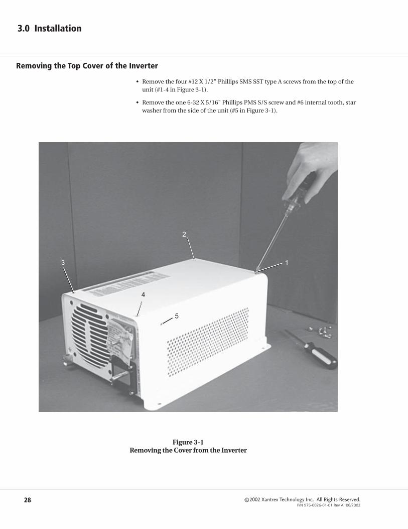
©2002 Xantrex Technology Inc. All Rights Reserved.P/N 975-0026-01-01 Rev A 06/2002
28
3.0 Installation
Removing the Top Cover of the Inverter
• Remove the four #12 X 1/2" Phillips SMS SST type A screws from the top of theunit (#1-4 in Figure 3-1).
• Remove the one 6-32 X 5/16" Phillips PMS S/S screw and #6 internal tooth, starwasher from the side of the unit (#5 in Figure 3-1).
Figure 3-1Removing the Cover from the Inverter
2
3 1
4
5

©2002 Xantrex Technology Inc. All Rights Reserved.P/N 975-0026-01-01 Rev A 06/2002
29
3.0 Installation
Figure 3-2aJumper Enlargement
Jumper Pins
JumperON
JumperOFF
Figure 3-2bJumper Placement
Configuring the Inverter’s Optional Battery Charger
When equipped with an optional battery charger, the UX inverter has threejumpers to control charger operation. A jumper is a small, rectangular piece ofplastic with two square holes in it, as shown in Figure 3-2a, that fit over two pinsas shown in Figure 3-2b. A jumper contains an internal conductor that joins thetwo pins completing a circuit. When the jumper is removed, the circuit isinterrupted. Jumpers are often used for changing configuration parameters.When a jumper is not connecting two pins, it can be stored by slipping it overjust one of the pins instead of both. This will have no effect upon theconfiguration but will keep the jumper handy for future use.
The jumpers in the UX inverter are located on the main circuit board and arelabeled SEALED, DEEP, and UPS. To access the jumpers, remove the top coverfrom the inverter following the instructions on page 28.
U20
E23E22
E15 E14
R135C56
C108C107
R137
R139
Q37
EBC
.047/630VC102
UP
SD
EE
PSE
ALED
C55
R14
0R1
36
R138
NO
NO
CO
M
NO
NO
NO
CO
M
NO
CO
M
R141
R14
2
Charger ConfigurationJumpers
Figure 3-2Location of the Optional Battery Charger Configuration Jumpers

©2002 Xantrex Technology Inc. All Rights Reserved.P/N 975-0026-01-01 Rev A 06/2002
30
3.0 Installation
Jumper Settings for the Optional Battery Charger
SEALED:
• JUMPER ON - If you are installing sealed batteries, the jumper remains acrossthis pair of pins. This selection sets the charge rate to 14.3 Vdc in the Bulk stageand 13.6 Vdc in the float stage.
• JUMPER OFF - For vented batteries, remove the jumper across these pins to setthe charge rate to 14.7 Vdc and 13.3 Vdc respectively.
DEEP:
• JUMPER ON - This pair of pins controls the amount of allowable batterydischarge. When the jumper connects these two pins, the inverter will allow thebatteries to discharge until completely drained.
• JUMPER OFF - When not installed, the inverter will not allow the batteries to bedischarged below 11.8 Vdc for more than five minutes.
UPS:
• JUMPER ON - This pair of pins controls the sensitivity of the charger tovariations in voltage from the AC source. When a jumper connects these twopins, the charger will stop charging and the inverter will provide AC powerwithin 35 milliseconds or less of an AC voltage drop to below 85-90 volts.
• JUMPER OFF - With the jumper removed, the shift from charger to inverter willbe delayed at least 200 milliseconds to allow AC voltage to return to normal. IfAC voltage does return to normal within this period, the charger will disengageand the inverter (when turned on) will provide AC power from the batteries.This prevents the charger from disengaging unnecessarily due to poor qualityvoltage. For generator charging, do not connect these pins.
Figure 3-3Battery Charger Jumper Settings
Jumper Location
©2002 Xantrex Technology Inc. All Rights Reserved.P/N 975-0026-01-01 Rev A 06/2002
31
3.0 Installation
Wiring Pre-Installation
Main Service Panel
If you have an inverter with the SB option, ensure you use the correct circuitbreaker based on the total current rating of your inverter. This circuit breakermust be located in the utility service panel.
See Table 3-5 on page 41 for maximum recommended breaker sizes.
Sub-Panel
Loads backed up by the inverter will need to be rerouted from the main servicepanel to a sub-panel. This can be done several different ways, depending uponthe installation. Always refer to electrical codes for safe wiring practices.
AC Circuit BreakersAlways use a properly rated circuit breaker. Depending upon the application,circuit breakers used to protect the load can be removed from the main servicepanel and put into the sub-panel ONLY if the two panels are from the samemanufacturer.
DC DisconnectInstall a DC disconnect breaker or fuse in the positive battery line. This breakerprotects the DC wiring in the event of an accidental short. Size the breaker inaccordance with the battery cables. Switch this breaker OFF whenever servicingthe batteries.
See DC Disconnect and Overcurrent Protection on page 35 for additionalinformation and recommended fuse sizes.
Wire Routing
Determine all wire routes both to and from the inverter and which knockouts arebest suited for connecting the AC conduits. Possible routing scenarios include:
• AC input wiring from the main utility service panel to the inverter
• AC input wiring from the generator to the inverter (if used)
• DC input wiring from the PV array (wind, hydro, etc.) to the inverter (if used)
• DC input wiring from the batteries to the inverter
• AC output wiring from the inverter to the sub-panel
• Battery temperature sensor cable from the batteries to the inverter (if used)
• Remote control cable to the inverter (if used)
• DC ground from the batteries to an external ground rod
• Load circuit wiring rerouted from the main service panel to the sub-panel
Check for existing electrical or plumbing prior to making cuts in the walls. Cutholes in the walls at appropriate locations for routing wiring/cables.

©2002 Xantrex Technology Inc. All Rights Reserved.P/N 975-0026-01-01 Rev A 06/2002
32
3.0 Installation
Inverter Mounting
The UX inverter is designed for either shelf-mounting or wall-mounting.
The UX inverter can weigh as much as 40 pounds (18.2 kg). Wallboard is notstrong enough to support this much weight so additional support must be added.The easiest method for securing the inverter to an existing wall is to place two2 x 4’s horizontally on the wall (spanning at least three studs) and securing theinverter to the 2 x 4’s.
Figure 3-4Wall-mounting Method (Not-to-Scale)
9 5/8"center to center
Wall studs 16 incheson center
Wallboard
Floor
2 x 4 mountingsupports
Ceiling
Approximately4 ft
Drill holes formounting here
12 1/32"(center to center)
Drill holes formounting here
12 1/32"(center to center)
WARNING: USEAPPROPRIATE LIFTINGTECHNIQUES. HAVEEXTRA PEOPLE ON HANDTO ASSIST IN LIFTINGTHE INVERTER INTOPOSITION WHILE IT ISBEING SECURED.

©2002 Xantrex Technology Inc. All Rights Reserved.P/N 975-0026-01-01 Rev A 06/2002
33
3.0 Installation
Wall-Mounting Procedure
1. Locate the studs and mark their location on the wall.
2. Measure the desired height from the floor for the inverter to be mounted.
3. Using a level, mark a horizontal line on the wall. The length of the line mustspan at least three studs.
4. Place a pre-cut 2 x 4 on the marked location and drill pilot holes through the2 x 4’s and studs.
5. Secure the 2 x 4 with #10 wood screws (length to penetrate 1½ inches into thestuds).
6. Repeat the procedure for the remaining 2 x 4.
7. Referring to Figure 3-5 or by using a cardboard template, drill out themounting hole locations for the inverter.
8. With assistance, lift the inverter into position and install it onto the 2 x 4’susing ¼ x 1½-inch lag bolts and washers.
Alternatively, a half or quarter sheet of ½-inch plywood can also be used as abacking, with the inverter mounted directly to the plywood using ¼-inchdiameter lag bolts and washers. The plywood must span three studs for adequatesupport.
Figure 3-5Dimensional Drawing for Screw Hole Placement
(Not to Scale)
NOTE: To make a simplecardboard template, placethe inverter on a piece ofcardboard and tracearound it. Mark themounting holes on thecardboard.

©2002 Xantrex Technology Inc. All Rights Reserved.P/N 975-0026-01-01 Rev A 06/2002
34
3.0 Installation
DC Wiring
Battery Cables
Proper cable sizing (diameter and length) is critical to the safe and efficientoperation of an inverter system. Larger diameter cables (smaller AWG number)have less voltage drop and are, therefore, more efficient when transferring powerto and from the batteries. If a cable is undersized (diameter too small), it couldpotentially overheat, creating a fire hazard.
Cable length is another important factor. Runs should be kept as short aspractical. Longer cable runs increase resistance, thus lowering the overallefficiency of the system. This is especially true in lower voltage systems where,depending upon the length of the cable run, it may be necessary to oversize thediameter of the wire, or parallel (double) the cables.
Battery cables must have crimped or soldered and crimped copper compressionlugs unless aluminum mechanical lugs are used. Soldered connections alone arenot acceptable. High quality battery cables are available from Xantrex in anassortment of lengths: 1½ to 10 feet, and in #2/0 AWG or #4/0 AWG sizes. Thesecables are color-coded with pressure crimped, sealed ring terminals.
See Table 3-2 below for minimum recommended cable size for batteries.
Table 3-2 provides recommended minimum cable sizes for various cable lengthsand inverter amperage. “Typical DC amps”, as shown in Table 3-2, is based onlow-battery voltage with an efficiency of 85%. Be sure to check with any localregulatory agencies for additional requirements.
Table 3-2Minimum Recommended Battery Cable Size Vs. Length
retrevnIledoM
lacipyTspmACD )yaw-eno(teeF3ot1 )yaweno(teeF5ot3 )yaw-eno(teeF01ot5
E215XU A55 mm6.33(GWA2# 2) mm4.76(GWA0/2# 2) mm4.76(GWA0/2# 2)
216XU A56 mm6.33(GWA2# 2) mm4.76(GWA0/2# 2) mm4.76(GWA0/2# 2)
2111XU A021 mm4.76(GWA0/2# 2) mm4.76(GWA0/2# 2) mm4.701(GWA0/4# 2)
E2111XU A021 mm4.76(GWA0/2# 2) mm4.76(GWA0/2# 2) mm4.701(GWA0/4# 2)
2151XU A051 mm4.701(GWA0/4# 2) mm4.701(GWA0/4# 2) mm4.701(GWA0/4# 2)
WARNING: UNDERSIZEDCABLES CAN OVERHEATAND MELT, CREATING AFIRE HAZARD WHENSUBJECTED TO HEAVY(PEAK) LOADS. ALWAYSUSE A PROPERLY SIZEDCABLE AND LENGTHRATED FOR THEAMPERAGE OF THEINVERTER AND BATTERIES.
NOTE: Use only copper cables.
NOTE: If the system includes a largebattery bank or large DCsource (such as a micro-hydroelectric plant or windgenerator), increasing thesize of the cables anddisconnects will greatlyreduce the number ofnuisance outages associatedwith breaker tripping andopen fuses.
NOTE: Run the positive andnegative battery cables asclose to each other aspossible by taping themtogether. This reduces theeffects of inductance andproduces a better waveformincreasing efficiency.

©2002 Xantrex Technology Inc. All Rights Reserved.P/N 975-0026-01-01 Rev A 06/2002
35
3.0 Installation
DC Wiring (continued)
DC Disconnect and Over-current Protection
For safety and compliance with regulations, battery over-current protection isrequired. Fuses and disconnects must be sized to protect the wiring in thesystem and are required to open before the wire reaches its maximum currentcarrying capability.
The National Electrical Code (NEC) requires both over-current protection and adisconnect switch for residential and commercial electrical systems. These itemsare not supplied as part of the inverter. However, Xantrex offers a DC circuitbreaker disconnect module specifically designed to meet NEC compliance. Twoamperage ratings are available: a DC250 (250 amps) and a DC175 (175 amps).
When sizing the DC disconnect, the expected continuous load on the invertershould be used to determine the DC current. Efficiency loss through the inverterincrease the DC current draw and must be accounted for. Divide the maximumcontinuous current draw by the inverter’s efficiency. Add a 25% safety margin tocomply with code requirements.
The term “free air” is defined by the NEC as cabling that is not enclosed in aconduit or a raceway. Cables enclosed in conduit or raceways have substantiallylower continuous current carrying ability due to heating factors.
Some installations may not require conduit or a disconnect device, althoughover-current protection is still required. Xantrex offers a fuse block (TFB)providing the code required inverter over-current protection for theseapplications. These fuses are available in 110, 200, 300, 350 and 400 amp sizes.
See Table 3-3 below for battery cable to maximum breaker/fuse size.
eziSelbaCderiuqeR
nignitaRtiudnoC
mumixaMrekaerB
eziS"riaeerF"nignitaR mumixaM
eziSesuF
GWA2# .xamspma511 A/N *.xamspma071 002BFT
GWA0/2# .xamspma571 571CD *.xamspma562 003BFT
GWA0/4# .xamspma052 052CD *.xamspma063 004BFT
Table 3-3Battery Cable to Maximum Breaker/Fuse Size
NOTE: for Table 3-3:
*The NEC allows roundingto the next standard fusesize from the cable rating(i.e.,150 amp cable sizerounds u to a standard175 amp size.)

©2002 Xantrex Technology Inc. All Rights Reserved.P/N 975-0026-01-01 Rev A 06/2002
36
3.0 Installation
DC Wiring (continued)
DC Grounding
The inverter’s chassis grounding lug is used to connect the chassis of the inverterto the DC grounding system. The terminal accepts wires from #14 AWG to#2 AWG.
Connect the negative (–) terminal of the battery bank to an appropriately sizedconductor and connect it to a solid earth ground, such as a grounding rod, driven6–8 feet into the earth. Xantrex DC disconnects include a grounding block for theDC negative to simplify grounding. This procedure will properly ground the DCcircuits.
Figure 3-6DC Grounding

©2002 Xantrex Technology Inc. All Rights Reserved.P/N 975-0026-01-01 Rev A 06/2002
37
3.0 Installation
DC Wiring (continued)
Battery Installation
1. Connect the positive cable between the battery’s positive terminal and the DCdisconnect/overcurrent protection device (torque to manufacture’srecommendations). The DC disconnect device should be located as close tothe batteries as possible.
2. Connect a cable between the DC disconnect device and the inverter’sPOSITIVE (+) terminal.
3. Connect the negative cable between the battery’s negative terminal (torque tomanufacture’s recommendations) and the inverter’s NEGATIVE (-) terminal.
4. Ensure the correct polarity of the cables with a DC voltmeter (DVM).
5. Use an insulated 1/2 inch wrench or socket to tighten the 5/16 SAE nuts to 10-15 foot/lb for each inverter input terminal.
6. Apply antioxidant paste to the battery, DC disconnect, and inverter’sterminals.
7. Install the battery terminal connection covers (red for positive, black fornegative) over the inverter’s DC terminals and secure with the screws andwashers provided.
WARNING: ENSURE THATTHE INVERTER IS OFFBEFORE CONNECTING ORDISCONNECTING THEBATTERY CABLES ANDTHAT ALL AC POWER ISDISCONNECTED FROM THEINVERTER’S INPUTS.
CAUTION: Verify the DCdisconnect device isswitched OFF.
CAUTION: Do not putanything between thecable ring terminal andthe flat metal part of theterminal. See Figure 3-7.Overheating of theterminal may occur. Donot apply any type ofantioxidant paste untilafter the battery cablewiring is tightened. Thesame applies for all DCconnections.
NOTE: Xantrex DC disconnect boxescontain a NEGATIVE DC blockwhich allows connectionbetween the battery andinverter’s negative terminals.The DC NEGATIVE block alsoprovides the negative/groundbonding for the DC system.
NOTE: For residential installations,NEC requires that “DCdisconnects” have bothovercurrent protection anda disconnect switch.
POSITIVE (+)RED TERMINAL
NEGATIVE (-)BLACKTERMINAL
ChassisGrounding
Lug
Figure 3-7Battery Cable Connections
#2/0 Copper Compression Lug #2/0 Aluminum Mechanical Lug
Do not place anythingbetween battery cable lug
and terminal surface.Assemble exactly as shown.

©2002 Xantrex Technology Inc. All Rights Reserved.P/N 975-0026-01-01 Rev A 06/2002
38
3.0 Installation
BatteryTemperatureSensor (BTS)(RJ11) Port
DC Wiring (continued)
Installing the Battery Temperature Sensor (BTS)
1. Insert the RJ11 connector on the battery temperature sensor wire into the BTSport located on the AC end of the inverter.
2. Secure the sensor to one of the batteries located in the center of the batterypack.
Figure 3-8BTS (RJ11) Port Location
Figure 3-9BTS Installed on Battery
NOTE: This accessory requires theinstallation of the SBOption on the inverter.
RJ11 Connector
Sensor

©2002 Xantrex Technology Inc. All Rights Reserved.P/N 975-0026-01-01 Rev A 06/2002
39
3.0 Installation
AC Wiring
Sub-panel Mounting
• Determine the location of the sub-panel and install it according to themanufacturer’s directions.
• Install an appropriate-sized circuit breaker in the sub-panel based on the wiresize being used from the inverter output. This will later be wired to the inverter’soutput.
Access to the Inverter’s AC Terminal Block
All AC wiring connects to the terminal block located on the left-hand side of theinverter.
• To access the terminal block, remove the two AC cover panels (if installed) byremoving the three Phillips screws. Units are shipped without the coversinstalled (packed in a small plastic bag with additional hardware).
• Locate the AC input and output terminals on the block.
See Figure 3-11 on page 42 for AC input wiring.
See Figure 3-12 on page 43 for AC output wiring.
WARNING: DISCONNECTTHE POWER FROM THEUTILITY’S MAIN BREAKERBOX BEFORE PROCEEDING.
NOTE: Installations should beperformed by a qualifiedperson or a licensedelectrician following alllocal and NEC codes.
CAUTION: The inverter’sAC output must never bewired to the utility orgenerator output. Thiswill cause severe damageto the inverter which isnot covered underwarranty.
Upper ACAccessPanel
Lower ACAccessPanel
Figure 3-10AC Access Covers and Hardware

©2002 Xantrex Technology Inc. All Rights Reserved.P/N 975-0026-01-01 Rev A 06/2002
40
3.0 Installation
AC Wiring (continued)
Electrical code requires that disconnect switches be provided in the AC input andoutput wiring circuits. AC circuit breakers in the AC load center can be used tomeet this requirement. The wiring, both in and out, of the inverter must also beprotected from short circuits and overloads by a fuse or circuit breaker. There aremany factors that determine the correct AC wire and breaker size based on yourinstallation. Consult with your national and local codes to determine the correctwire and breaker size based on the current requirements for your particularmodel shown in the table below.
NOTE: Consult the NEC for actualwire sizes for specificinstallations.
Table 3-4AC Current Requirements (Input and Output)
LEDOMTUPNI TUPTUO
)regrahcrofspma(urht-ssaP latoT
E215XU elbaliavatoN spma2.2
BSE215XU )spma5.2(spma51 spma51
216XU elbaliavatoN spma5
BS216XU )spma5(spma03 spma03
2111XU elbaliavatoN spma2.9
BS2111XU )spma01(spma03 spma03
E2111XU elbaliavatoN spma8.4
BSE2111XU )spma5(spma51 spma51
2151XU elbaliavatoN spma5.21
BS2151XU )spma31(spma03 spma03

©2002 Xantrex Technology Inc. All Rights Reserved.P/N 975-0026-01-01 Rev A 06/2002
41
3.0 Installation
Table 3-5 is provided as a guide to help determine the minimum AC wire sizeneeded and may be different based on your particular installation. AC wire sizesprovided in Table 3-5 are from the NEC and assume the use of conduits, usingcopper wire, and with a temperature rating of 75 °C or higher. A minimum of#14 AWG is required for all AC wiring.
Consult your local code for more information and for other wire and breakersizes.
Table 3-5Minimum Recommended AC Wire Size (Input and Output)
AC Wiring (continued)
LEDOMTUPNI TUPTUO
eziSrekaerBmumixaM/eziSeriW eziSrekaerBmumixaM/eziSeriW
E215XU elbaliavAtoN spma51/GWA41#
BSE215XU spma51/GWA41# spma51/GWA41#
216XU elbaliavAtoN spma51/GWA41#
BS216XU spma03/GWA01# spma03/GWA01#
2111XU elbaliavAtoN spma51/GWA41#
BS2111XU spma03/GWA01# spma03/GWA01#
E2111XU elbaliavAtoN spma51/GWA41#
BSE2111XU spma51/GWA41# spma03/GWA01#
2151XU elbaliavAtoN spma51/GWA41#
BS2151XU spma03/GWA01# spma03/GWA01#

©2002 Xantrex Technology Inc. All Rights Reserved.P/N 975-0026-01-01 Rev A 06/2002
42
3.0 Installation
AC Wiring (continued)
AC Input Wiring to Inverter (only for inverters with the SB Option installed)
1. Install an appropriate sized circuit breaker in the main utility breaker box.This will serve as both an AC disconnect and over-current protection.
See Table 3-5 on page 41 for maximum breaker sizes.
2. Feed the HOT, NEUTRAL and GROUND wires (via conduit) from the inverterto the main utility breaker box. Leave several inches of extra wire at each end.
3. Make the connections to the inverter first. Wiring to the main utility breakerbox is performed after all connections have been made in the inverter.
a. Connect the GROUND (green) wire to the inverter’s AC GROUNDterminal.
b. Connect the NEUTRAL (white) wire from the main utility breaker box tothe inverter’s NEUTRAL INPUT terminal.
c. Connect the HOT (black) wire from the main utility breaker box to theinverter’s AC HOT INPUT terminal.
4. Torque all connections to 16 inch-pounds.
WARNING: DISCONNECTTHE MAIN BREAKER AT THEMAIN UTILITY BREAKERBOX. DISCONNECT THEBATTERY CONNECTIONSFROM THE INVERTER IFTHEY ARE ALREADYCONNECTED.
AC GroundNEUTRAL INHOT IN
Figure 3-11AC Input Wiring

©2002 Xantrex Technology Inc. All Rights Reserved.P/N 975-0026-01-01 Rev A 06/2002
43
3.0 Installation
AC Wiring (continued)
AC Output Wiring to the Sub-panel
1. Connect the GROUND wire to the inverter’s AC GROUND chassisterminal. Connect the other end of this wire to the GROUND bus in thesub-panel.
2. Connect the NEUTRAL (white) wire to the inverter’s NEUTRALOUTPUT terminal. Connect the other end of this wire to the NEUTRALbus in the sub-panel.
3. Connect the HOT (black) wire to the inverter’s terminal labeled ACHOT OUTPUT. Connect the other end of this wire to the sub-panel’sinput circuit breaker.
4. Torque all inverter terminal block connections to 16 inch-pounds.Refer to the sub-panel manufacturer’s specifications for wire torques atthe sub-panel.
Figure 3-12AC Output Wiring
AC Ground NEUTRALOUT
HOTOUT
WARNING: ENSURE THESUB-PANEL DOES NOTHAVE A NEUTRAL TOGROUND BOND. IF ITDOES, REMOVE IT. ALL ACNEUTRAL-GROUNDBONDING IS DONE AT THEMAIN UTILITY BREAKERBOX (SERVICE ENTRANCE).
NOTE: The two neutralconnections (input andoutput) are common to oneanother and may be used inany combination.
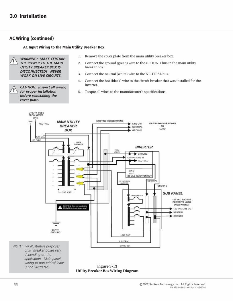
©2002 Xantrex Technology Inc. All Rights Reserved.P/N 975-0026-01-01 Rev A 06/2002
44
3.0 Installation
AC Wiring (continued)
AC Input Wiring to the Main Utility Breaker Box
1. Remove the cover plate from the main utility breaker box.
2. Connect the ground (green) wire to the GROUND bus in the main utilitybreaker box.
3. Connect the neutral (white) wire to the NEUTRAL bus.
4. Connect the hot (black) wire to the circuit breaker that was installed for theinverter.
5. Torque all wires to the manufacturer’s specifications.
Figure 3-13Utility Breaker Box Wiring Diagram
WARNING: MAKE CERTAINTHE POWER TO THE MAINUTILITY BREAKER BOX ISDISCONNECTED! NEVERWORK ON LIVE CIRCUITS.
CAUTION: Inspect all wiringfor proper installationbefore reinstalling thecover plate.
NOTE: For illustrative purposesonly. Breaker boxes varydepending on theapplication. Main panelwiring to non-critical loadsis not illustrated.

©2002 Xantrex Technology Inc. All Rights Reserved.P/N 975-0026-01-01 Rev A 06/2002
45
3.0 Installation
Generators
Basic 120 Vac Generator Hookup (Off-Grid applications only)
1. Connect the ground wire on the generator to the GROUND terminal on theinverter.
2. Connect the generator neutral wire to the NEUTRAL terminal on the inverter.
3. Connect the generator HOT wire to the HOT input on the inverter.
4. Bond the neutral to the ground on the output of the generator (only if used innon-utility installations) or in the main utility breaker box (not both).
5. Drive a ground rod 6–8 feet (1.8 - 2.4 meters) into the ground and connect thegenerator’s ground to the ground rod.
6. Start the generator and check for proper operation of the inverter (i.e., theinverter transfers from battery to generator power).
Figure 3-14Basic 120 Vac Generator Block Diagram (for Off-Grid applications)
120 VACGENERATOR
HOTNeutral
GroundNeutral/Ground bond
HOTNeutralGround
HO
T
Neu
tral
Gro
und
INVERTER/CHARGER
120 VACLOADS
NOTE: The ground and neutralmust be bonded at oneplace, and only one place, inthe system. If the generatoris the main source of power,(i.e., no utility grid power)then the neutral and groundconnections are bonded atthe generator. If thegenerator is acting as abackup for the utility grid,then the bond should be atthe main utility breaker box.In this case, ensure that nobond exists at the generatoroutput.

©2002 Xantrex Technology Inc. All Rights Reserved.P/N 975-0026-01-01 Rev A 06/2002
46
3.0 Installation
Generators (continued)
Basic 120 Vac Utility/Generator Hookup
If a generator is used as a backup for the utility, then an AC transfer switch mustbe added to provide a means to switch the generator power to the inverter’sinputs. The generator can be used during extended outages to recharge thebatteries and provide pass-through power for the loads. Start and stop thegenerator manually using the generator’s pull-cord, ON/OFF switch, etc.
See Figure 3-15 for a basic 120 Vac utility/generator block diagram.
Generator Connections (to AC transfer switch)
1. Connect a (green) ground wire between the generator’s GROUND terminaland the GROUND terminal in the AC transfer switch.
2. Connect a (white) neutral wire between the generator’s NEUTRAL terminaland the NEUTRAL bus in the AC transfer switch.
3. Connect a (black) HOT wire between the generator’s HOT OUT terminal andthe generator’s HOT contact in the AC transfer switch.
Utility Connections (to AC transfer switch)
1. Connect a (green) wire between the GROUND terminal in the main utilitybreaker box and the GROUND terminal in the AC transfer switch.
2. Connect a (white) wire between the NEUTRAL bus in the main utility breakerbox and the NEUTRAL bus in the AC transfer switch.
3. Connect a (black) wire between the inverter circuit breaker in the main utilitybreaker box and the utility HOT contact in the AC transfer switch.
Inverter Connections (to AC transfer switch)
1. Connect a (green) wire between the GROUND terminal in the AC transferswitch and the inverter’s AC GROUND terminal.
2. Connect a (white) wire between the NEUTRAL terminal in the AC transferswitch and the inverter’s NEUTRAL IN terminal.
3. Connect a (black) wire between the COMMON terminal in the AC transferswitch and the inverter’s HOT IN terminal.
4. Torque all wires 16 in/lb.
Sub-panel Connections
1. Connect a (green) wire between the inverter’s AC GROUND terminal and theGROUND terminal in the sub-panel.
2. Connect a (white) wire between the inverter’s NEUTRAL OUTPUT terminaland the NEUTRAL bus in the sub-panel.
3. Connect a (black) wire between the inverter’s terminal labeled AC HOTOUTPUT and the sub-panel’s INPUT circuit breaker.
4. Torque all inverter terminal block connections to 16 in/lb. Refer to the sub-panel manufacturer’s specifications for wire torques.
5. Recheck all connections.
NOTE: Refer to the AC transferswitch installation manualfor contact details, torquespecifications, etc.

©2002 Xantrex Technology Inc. All Rights Reserved.P/N 975-0026-01-01 Rev A 06/2002
47
3.0 Installation
Generators (continued)
Figure 3-15Basic 120 Vac Utility/Generator Block Diagram

©2002 Xantrex Technology Inc. All Rights Reserved.P/N 975-0026-01-01 Rev A 06/2002
48
3.0 Installation
Remote Monitoring
The UX inverter/charger can be controlled remotely by installing an RC8Remote Control.
See Figure 3-16 below for the location of the RC8 Remote Control port on theUX inverter/charger.
See the RC8 Remote Control Installation Guide for specific installationinstructions for installing the RC8 remote control.
Figure 3-16Remote Monitor Port Location
RC8 RemoteControl Port

©2002 Xantrex Technology Inc. All Rights Reserved.P/N 975-0026-01-01 Rev A 06/2002
49
4.0 Operation
This section describes the operation of the UX Series inverter/charger. Thecontrols on the inverter are very straightforward.
Control PanelThe figure below shows the control panel, located on the left side (AC end) of theinverter.
Figure 4-1Control Panel
Standby Charger AC Input breaker(SB Option Only)
(Plugged if no charger is installed)
Status LightLegend
Search SensitivityControl
(Turn full counter-clockwise to defeat)
RC8 RemoteON/OFF port
Standby Charger Status LEDShows yellow when charging
(SB Option Only)
Power: PushON/OFF
Battery Tempera-ture Sensor (BTS)
Port(SB Option Only)
Green Status LED
AC Output Breaker

©2002 Xantrex Technology Inc. All Rights Reserved.P/N 975-0026-01-01 Rev A 06/2002
50
4.0 Operation
Control Panel (continued)
Power ON/OFF Button
This button turns the inverter on and off: on initial power up, after connectingthe batteries, press it twice. The ON/OFF button also resets the inverter in theevent it shuts down completely due to a fault condition. To reset the unit after afault condition, press the ON/OFF button only one time. The ON/OFF buttonturns off only the inverter portion of the unit. Anytime AC input power ispresent, the battery charger section (if installed) will be operable.
Green Status LED• Steady: Unit is inverting.
• Fast blinking: Unit is in search mode.
• Fast, erratic blinking: Indicates an error condition, such as a low-batteryvoltage, high-battery voltage, overheating, or over-current condition. (Almostlooks like a “flicker”.)
Yellow Charger Status LEDIf your unit is equipped with the optional standby charger, this yellow LED will belit when the unit is charging. The greater the charging current, the brighter theLED will shine. When battery voltage is far below full charge, the LED will glowbrightest. When the LED is not illuminated, battery voltage is higher than boththe Absorb and the Float voltage charging threshold or another charger isconnected in parallel with the unit.
Search Sense ModeThe inverter incorporates a power-saving “Search Sense Mode” that minimizespower drain when there is no load connected by reducing the inverter’s output tobrief test pulses. When a load exceeding the threshold specified on the controlpanel is detected, the inverter’s output goes to full voltage. The sensitivitythreshold is adjustable from about 5 watts to 100 watts. When the inverter is insearch mode, the LED will slowly flash green.
Search Control Knob: The control panel knob labeled “Search” sets thesensitivity level in watts that will activate the inverter. Turn the knob fullcounterclockwise to “Defeat” or disable the search mode. The adjustment rangeis from 5 to 100 watts.
If problem loads can’t be eliminated, disable the Search Sense Mode and theinverter will always remain at full output voltage.
See Section 5, Troubleshooting, page 58, for more information about potentialproblem loads when using Search Mode.
Search Sense Operation
While idling in Search Sense Mode, the inverter sends out a pulse about six timesper second. This electrical pulse travels through the AC wiring “looking” forloads that are connected to the system.
When a load is detected, the inverter determines the wattage of the load andchecks to see if it is greater than the threshold set by the operator. This thresholdpoint is adjustable with the Search Control knob on the control panel. Thelowest setting is about 5 watts and the highest setting is 100 watts.

©2002 Xantrex Technology Inc. All Rights Reserved.P/N 975-0026-01-01 Rev A 06/2002
51
4.0 Operation
Control Panel (continued)
Search Sense Operation (continued)
For example: when the search sensitivity threshold is set at 40 watts and no loadsare present that are 40 watts or greater, the inverter will “ignore” any loads lessthan 40 watts and remain in idle mode. When a load greater than 40 wattsappears, the inverter comes out of idle mode and applies power to the load.
The Search Sense Mode may be disabled by turning the Search Control knobcounterclockwise all the way to “Defeat.” The inverter remains at full outputvoltage at all times.
Benefits of Using Search Sense
Search Sense allows you to selectively operate only loads that draw more than aspecified amount of power, which means power savings. The inverter needs5 watts to power itself, even when there are no loads to power.
For example: if a water pump is driven by an inverter for only one hour each day,the other twenty-three hours of the day the inverter is consuming five watts perhour while idle. This power comes from the batteries.
By setting the search sensitivity so that the inverter idles until the water pump triesto run, power savings are realized.
Instead of idling at 5 watts, the inverter consumes only ½ watt while in searchmode. This is a savings of 4½ watts every hour or 108 watt hours per day. Thisconverts directly to 8.6 amp hours at 12.6 Vdc (12 V nominal).
In systems with small batteries or limited charging capability, this can lead tosubstantial savings.
Setting Up Search Mode
The search sense feature significantly reduces battery drain when the inverterspends a fair amount of time “sleeping” each day. Therefore, if search sense is tobe utilized it must be adjusted properly. The initial adjustment should be madeso that the inverter comes on only when needed.
1. Determine the smallest load that will trigger the inverter out of search mode.
2. Turn the sensitivity control all the way to the lowest setting.
3. Turn on the desired load.
4. Turn the sensitivity up until the load just turns on (if loads changesignificantly, retuning of the search sensitivity will be necessary).
Some TVs have a menu or control to disable instant-on circuits. If clocks are aproblem load, use battery powered units.
A solution might be to place all problem loads on one circuit with one masterdisconnect.
See Section 5, Troubleshooting, page 58, for more information about potentialproblem loads when using Search Mode.

©2002 Xantrex Technology Inc. All Rights Reserved.P/N 975-0026-01-01 Rev A 06/2002
52
4.0 Operation
Standby (SB) Option
Units equipped with the standby (SB) option have an additional LED and circuitbreaker on the front panel.
See Figure 4-2 on page 53 for the location of the Standby Charger Status LEDand SB Charger AC Input Breaker.
SB Option Operation
The standby option adds an internal battery charger and automatic transfer relay.This allows the unit to operate as either a battery charger or inverter (but notboth at the same time). An external source of AC power (e.g., utility or generator)must be supplied to the inverter’s AC input in order to allow it to operate as abattery charger. When the unit is operating as a charger, it’s AC output ispowered by the external source (i.e., generator or utility).
The inverter automatically becomes a battery charger whenever AC power isdelivered to its AC inputs. There is a 15 second time delay from the time theinverter senses that AC is present at its input and when the transfer is made. Thisdelay is built in to provide time for a generator to spin-up to a stable voltage andavoid relay chattering. While in the battery charger mode, the inverter’s AC inputis internally connected to the inverter’s AC output.
For 120 Vac units, 30 amps is the maximum power that can be handled by theinverter’s internal wiring and transfer relay. For 230 Vac units, 15 amps is themaximum power that can be handled by the inverter’s internal wiring andtransfer relay. This amperage can be passed directly from the AC input to the ACoutput. During heavy charging, part of this input amperage will be consumed bythe charger.
Transfer Switching SpeedWhile this inverter is not designed specifically as a uninterruptable power supply(UPS) system, its transfer time is normally fast enough to support computers.The transfer time is approximately 35 milliseconds when switching from chargerto inverter mode.
When switching from inverter to charger, the inverter waits approximately15 seconds to ensure the AC source is stable (generator up to speed) and thenmakes the transfer in approximately 30 milliseconds.
Success as a UPS will vary with computer models and cannot be guaranteed.

©2002 Xantrex Technology Inc. All Rights Reserved.P/N 975-0026-01-01 Rev A 06/2002
53
4.0 Operation
Battery Charger LED Indicator
A yellow LED located on the lower control panel reports the status of the batterycharger.
Figure 4-2Battery Charger Status LED
Standby ChargerStatus LED showssolid yellow whenin charge mode
Battery ChargerAC Input Breaker
©2002 Xantrex Technology Inc. All Rights Reserved.P/N 975-0026-01-01 Rev A 06/2002
54
4.0 Operation

©2002 Xantrex Technology Inc. All Rights Reserved.P/N 975-0026-01-01 Rev A 06/2002
55
Table 5-1Troubleshooting the UX Model Inverter/Charger
NOTE: The UX Series inverter/chargerhas no internal userserviceable parts. If service isrequired, refer to Appendix C.
5.0 Troubleshooting
The following information is provided to help identify the source of the problemif the system doesn’t perform as expected.
MOTPMYS MELBORPELBISSOP YDEMER
.rewoptuptuooN.FFOerasDEL
yrettabehtroFFOdehctiwssitinUwolootsiegatlov
ehtkcehC.notinuehthctiwStiucric,sesuf,egatlovyrettab
.snoitcennocelbacdnasrekaerb
.rewoptuptuooNgnihsalfsiDELSUTATSneerG
.)tsaf(egatlovyrettabwoL
ehttaegatlovyrettabehtkcehC,egrahC.slanimrets'retrevni
.seirettabecalperro,egrahcsid
.rewoptuptuooNgnihsalfsiDELSUTATSneerG
.)wols(
hcraesehtrofllamsootdaoLtcetedottiucricedom
rodlohserhthcraesehtecudeR.edomhcraestaefed
.rewoptuptuowoL.FFOdnaNOsdaolsnrutretrevnI
gnihsalfsiDELSUTATSneerG.)tsaf(
seirettabwoL .seirettabegrahcerdnakcehC
yrettabdedorrocroesooLsnoitcennoc .snoitcennocllanaelcdnakcehC
snoitcennoctuptuoCAesooL .snoitcennoctuptuoCAkcehC
wolsraeppaegatlovtuptuoCA.retemagnisunehw
epytgnorwehthtiwgnirusaeM)caV001-08syalpsid(retemtlov
SMReurtaebtsumretemtloV.retemgnidaer
.rewopegruswoL ootselbacyrettab,seirettabkaeWgnolootrollams
yrettabdnaelbacotrefeR.launamnisnoitadnemmocer
.etaregrahcwoL
nehw(egatlovtupniCAkaepwoL)rewopdirgytilituotdetcennoc
tsujdA.gniriwtupniCAkcehCetomermorfgnittesetaregrahc
.daolecuderro
egatlovtupniCAkaepwoL nehw()rotarenegagnisu
norotalugeregatlovehttsujdAkaepstlov461(.rotarenegeht.)tuptuoregrahcllufrofderiuqer
otllamsootsituptuorotareneGregrahcdnadaolrewop .daolecudeR
.evitareponisiregrahC
dabroselbacyrettabesooLseirettab .seirettabdnaselbackcehC
tesylreporpmislortnocregrahC .seirettabdnaselbackcehC
egatlovtupniCAgnorW reporproftupniCAkcehC.ycneuqerfdnaegatlov

©2002 Xantrex Technology Inc. All Rights Reserved.P/N 975-0026-01-01 Rev A 06/2002
56
5.0 Troubleshooting
Potential Problem Loads for the Inverter
The inverter can operate most AC loads. However, there are special conditionsthat can cause a load to behave differently than expected. The followingdescribes some of the common problems encountered when using an inverter.
Ceiling Fans
Most large-diameter, slow turning fans run correctly, but generate more noisethan when connected to utility power. High speed fans tend to operate normally.
Cell PhonesSome cellular telephones experience interference in the form of a clicking sound.
Computers and Sensitive ElectronicsSome computers and sophisticated electronics have power supplies that do notpresent a load until correct line voltage is available. When this occurs, each unitwaits for the other to begin. This can usually be solved by plugging in anadditional load (such as a lamp) to bring the inverter out of its search mode.Avoid starting large loads when using a computer .
Consumer ElectronicsAM radios tend to pick up inverter noise, especially on the lower half of theirband. Inexpensive tape recorders are likely to experience noise as well. Avoidstarting large loads when using sensitive electronic devices.
ClocksThe inverter’s crystal controlled oscillator keeps the frequency accurate to withina few seconds a day; however, external loads in the system may alter the inverter’soutput waveform causing clocks to run at different speeds. There may be periodswhere clocks keep time correctly and then mysteriously do not. This is becausemost clocks do not draw enough power to trigger the load sensing circuit. In orderto operate, especially with no other loads present, the inverter’s load sensingcircuit will have to be defeated.
Decreasing LoadsIf the amount of power a load draws decreases after it has been switched on (suchas with a small motor) and its current draw becomes less than the load sensingthreshold, it will be turned alternately ON and OFF by the inverter. This canusually be solved by plugging in an additional load (such as a lamp).
CAUTION: Some of theseproblem loads can causeirreparable damage to theload itself. Please contact aCustomer ServiceRepresentative for morespecific information beforeusing any of these itemswith the UX inverter.

©2002 Xantrex Technology Inc. All Rights Reserved.P/N 975-0026-01-01 Rev A 06/2002
57
5.0 Troubleshooting
Potential Problem Loads for the Inverter (continued)
Dimmer Switches
Most dimmer switches lose their ability to dim the lights when used with aninverter and operate only in the fully ON or OFF position. Newer dimmerswitches controlled by microprocessors tend to work better in inverterapplications.
Fluorescent LightsSome devices cannot be detected by the inverter’s load sensor and will notoperate. Small fluorescent lights are the most common example. This can usuallybe solved by plugging in an additional load.
Heavy LoadsIf the battery-bank cannot deliver the necessary amperage to operate a heavyload, the inverter will shut down. The battery voltage will then slowly rise backabove the low-voltage threshold causing the inverter to resume operation. Thiscycling of the inverter will continue until the heavy load is reduced or anadditional source of power is added.
Microwave OvensMicrowave ovens are sensitive to peak output voltages. The higher the voltage,the faster they cook. Since the inverter’s peak output voltage is dependent uponbattery voltage and load size, the microwave’s cook time may need to beincreased.
PrintersMost inkjet type printers work well in inverter applications. Laser printers,however, require a high current for their fusing circuit and are not recommendedfor use with an inverter.
Rechargeable Devices
When first using a rechargeable device, monitor its temperature for 10 minutes toensure it does not become abnormally hot. Excessive heat will indicate that it isincompatible with the inverter.
Undersized LoadsIf the power consumed by a device is less than the inverter’s search modecircuitry threshold, it will not run. This can usually be solved by plugging in anadditional load such as a 100-watt light bulb.
CAUTION: Do not run alaser printer using the UXinverter for power.

©2002 Xantrex Technology Inc. All Rights Reserved.P/N 975-0026-01-01 Rev A 06/2002
58
5.0 Troubleshooting
Potential Problem Loads related to Search Sense Mode
Some loads can “fool” the Search Sense Mode, causing the unit to cycle on and off,or not to turn on at all.
Confirming Search Mode Operation
A neon-type nightlight can be used as a test indicator to show whether theinverter is searching for loads. Plug the night light into the wall–if the inverter isin search mode the light will blink, showing the search pulses sent out by theinverter. If the inverter is running a load, the light will be on continuouslybecause continuous power is being delivered to a load. A typical incandescentnightlight may also work to show the pulses, but it will use more power.
Incandescent Lights
Incandescent lights have a higher starting wattage when the filament is cold thanthe continuous rating of the bulb. For example: if the inverter is set to sense a40-watt load, and a 30-watt bulb is turned on, the inverter will initially sense aload because the bulb’s cold-starting wattage will exceed the 40-watt threshold .When the bulb warms up, it will draw less than the threshold wattage, the inverterwill revert to idle mode and the light will go off. When the light cools, its load willagain exceed the threshold and the cycle will repeat.
Fluorescent Bulbs
These work the opposite of incandescent light bulbs. If the inverter is set todetect a 30-watt load and a 40-watt fluorescent light is switched on, the inverterwill not detect it because fluorescent tubes draw less than 30 watts until the gas inthe tube ionizes.
Other loads
Some appliances draw power even when turned off. Examples of this aretelevision sets equipped with instant-on circuits, microwaves equipped withdigital clocks, VCRs, and other clocks. If the search sensitivity threshold is sethigher than the combined loads, an auxiliary load must be used to bring theinverter out of search mode before the appliances will turn on.
If the sensitivity threshold is set lower than the combination of the loads, the loadswill remain on continually, and excess battery drain will occur. Three such 15-wattloads would consume an additional 90 amp hours per 24 hours in a 12 Vdc system.Some alternatives are:
• turn the item off at the wall,• use an extension cord equipped with an on/off switch,• place an on/off switch at the outlet, or• install an appropriate circuit breaker.

©2002 Xantrex Technology Inc. All Rights Reserved.P/N 975-0026-01-01 Rev A 06/2002
59
5.0 Troubleshooting
L1L2
NeutralGround
Black–Hot
White–Neutral
Bare–Ground
120 VAC120 VAC
240 VACfrom Grid
25 A
25 A
25 A
25 A
25 ABreaker
Black–Hot
Bare–Ground
White–Neutral
Load Center
25 ABreaker
Figure 5-1Conventional “Home-run” Type Wiring
Multiwire Branch Circuits
A potential safety problem exists when installing stand-alone 120 Vac invertersinto existing 120/240 Vac wired panels where multiwire branch circuit wiringmethods were used.
Multiwire branch circuits are wired differently from “home run” type wiring inthat only one neutral wire is used to provide the neutral-return path for eachcircuit connected to both phases of the AC grid. This method has been employedby electricians in recent years to keep construction costs down by saving copperand labor costs involved in running separate “romex” for each circuit.
See Figure 5-1 below for a diagram of conventional “Home-run” type wiring.
Under normal conditions, this technique is quite safe and meets coderequirements. When used as originally installed, the current for each circuit is180° out-of-phase with each other, so the neutral wire never receives morecurrent than it was designed to handle as the current from each circuit subtracts(or cancels out–leaving only the difference current between the two circuits).
A safety problem occurs when a stand-alone 120 Vac inverter is installed to powerthese circuits, causing the one neutral wire to now carry the in-phase currents forboth circuits. Since the current is in-phase, the two circuits add instead ofsubtract, potentially doubling the current flow in the neutral return wire! Thebranch circuit breakers do not protect the neutral wire from overload under thiscondition. This excess current will overheat the neutral wire, potentially creatinga fire hazard.
See Figure 5-2 on page 60 for a diagram of multiwire branch circuit wiringand current flow.
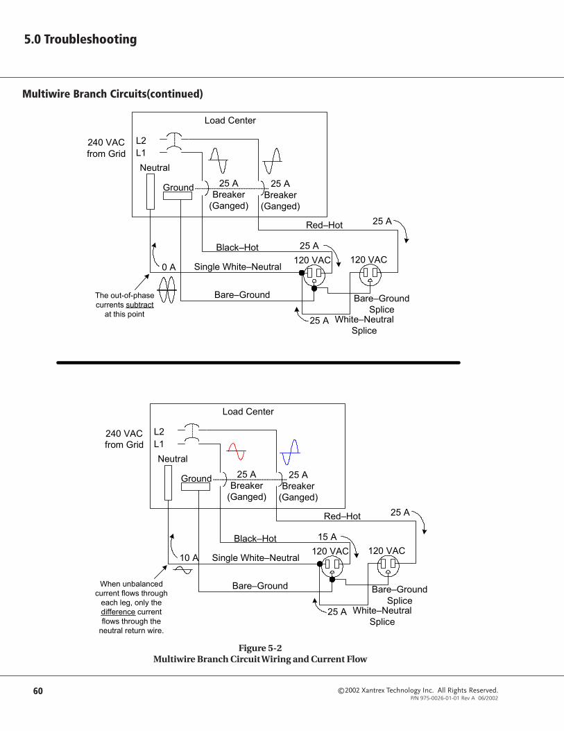
©2002 Xantrex Technology Inc. All Rights Reserved.P/N 975-0026-01-01 Rev A 06/2002
60
5.0 Troubleshooting
Figure 5-2Multiwire Branch Circuit Wiring and Current Flow
L1L2
Neutral
Ground
Black–Hot
Single White–Neutral
Bare–Ground
120 VAC120 VAC
240 VACfrom Grid
25 A
0 A
25 A
25 ABreaker
(Ganged)
Red–Hot
Load Center
25 A White–NeutralSplice
The out-of-phasecurrents subtract
at this point
25 ABreaker
(Ganged)
Bare–GroundSplice
L1L2
Neutral
Ground
Black–Hot
Single White–Neutral
Bare–Ground
120 VAC120 VAC
240 VACfrom Grid
25 A
10 A
15 A
25 ABreaker
(Ganged)
Red–Hot
Load Center
25 A White–NeutralSplice
When unbalancedcurrent flows through
each leg, only thedifference currentflows through the
neutral return wire.
25 ABreaker
(Ganged)
Bare–GroundSplice
Multiwire Branch Circuits(continued)

©2002 Xantrex Technology Inc. All Rights Reserved.P/N 975-0026-01-01 Rev A 06/2002
61
5.0 Troubleshooting
Figure 5-3120 Vac Inverter Incorrectly Wired in a Multiwire Branch Circuit
Multiwire Branch Circuits (continued)

©2002 Xantrex Technology Inc. All Rights Reserved.P/N 975-0026-01-01 Rev A 06/2002
62
5.0 Troubleshooting
Identifying Multiwire Branch Circuits
Multiwire branch circuits can be identified by removing the cover on the loadcenter and inspecting the wiring. Conventional 120 Vac circuits are identified bya 2-wire-plus-ground (black, white and copper) “romex” for each circuit.Multiwire branch circuits use a 3-wire-plus-ground arrangement (black, red,white and copper) for each circuit run.
See Figure 5-4 for an illustration showing the wire used in multibranchwiring.
Figure 5-4Multiwire Branch Circuit Wire
WARNING: THE NEXT STEPINVOLVES OPENING THELOAD CENTER EXPOSINGLIVE CIRCUITS. THISPROCEDURE SHOULDONLY BE PERFORMED BYQUALIFIED PERSONS ORELECTRICIANS.
WARNING: IF THISARRANGEMENT EXISTS INTHE PANEL AND IT ISBEING POWERED BY ASTAND-ALONE 120 VACINVERTER, A POTENTIALFIRE HAZARD EXISTS! FORSAFETY, THESE CIRCUITSMUST BE REWIRED TOMEET CODEREQUIREMENTS.

©2002 Xantrex Technology Inc. All Rights Reserved.P/N 975-0026-01-01 Rev A 06/2002
63
5.0 Troubleshooting
Multiwire Branch Circuits (continued)
Correcting Multiwire Branch Circuit Wiring
Correcting multiwire branch circuit wiring is not an easy task. There are severalapproaches that can be taken, each with its advantages and disadvantages.
• Rewire existing multiwire branch circuits to conventional “home run” wiring.This requires a qualified electrician (knowledgeable of multiwire branch circuitwiring) and is expensive. There may be multiple multiwire branch circuitslocated throughout the structure, requiring complete rewiring.
• Add a T240 autotransformer to the output of the inverter to restore the split-phase configuration. This is the least expensive and easiest method to correct formultiwire branch circuit wiring. Using this method, half of the current issupplied to one leg of the circuit and half to the other in a split-phasearrangement (180° out-of-phase). This will restore the original functionality andsafety to the multiwire branch circuit.
See Figure 5-5 for a diagram using a T240 Autotransformer in multiwirebranch circuit wiring.
Figure 5-5Using A T240 Autotransformer in Multiwire Branch Circuit Wiring
WARNING: UNTIL ONE OFTHE SOLUTIONS ABOVE ISIMPLEMENTED, A STAND-ALONE 120 VAC INVERTER(OR GENERATOR) MUSTNOT BE INSTALLED WHEREMULTIWIRE BRANCHCIRCUITS EXIST.
©2002 Xantrex Technology Inc. All Rights Reserved.P/N 975-0026-01-01 Rev A 06/2002
64
5.0 Troubleshooting
Notes:

©2002 Xantrex Technology Inc. All Rights Reserved.P/N 975-0026-01-01 Rev A 06/2002
A-1
UX612 UX1112 UX1512 UX512E/SB UX1112E/SBInput (DC)Input Voltage (rated) 12 VDC 12 VDC 12 VDC 12 VDC 12 VDCInput Voltage Range 10 to 16 VDC 10 to 16 VDC 10 to 16 VDC 10 to 16 VDC 10 to 16 VDCSearch Mode (typical) <1 W <1 W <1 W <1 W <1 WOn Mode (no load - idle) 5 watts 5.5 watts 7 watts 5 watts 5.5 watts
Input (AC)Input Voltage 120 VAC 120 VAC 120 VAC 230 VAC 230 VACInput Frequency 60 Hz 60 Hz 60 Hz 50 Hz 50 HzInput / Pass-through Current (max) 30 A 30 A 30 A 15 A 15 A
OutputOutput Voltage (rms) 120 VAC 120 VAC 120 VAC 230 VAC 230 VACOutput Frequency 60 Hz 60 Hz 60 Hz 50 Hz 50 HzContinuous Output Current 3.4 A 5 A 6.7 A 2.1 A 4.8 AContinuous Power 400 VA 600 VA 800 VA 500 VA 1100 VASurge Capability
1 mSec (1) 25 A (peak) 38 A (peak) 38 A (peak) 12 A (peak) 14 A (peak)100 mSec (2) 22 A (rms) 22 A (rms) 25 A (rms) 11 A (rms) 11 A (rms)
Peak Efficiency 92% 92% 92% 92% 92%
Battery ChargerMaximum Charging Rate 25 A 50 A 65 A 25 A 50 ASelectable Charging Rate (default) Sealed Batteries: 14.3 VDC (Bulk) / 13.6 VDC (Float)
Vented Batteries: 14.7 VDC (Bulk) / 13.4 VDC (Float)Charger Type 3-stage (Bulk, Absorption, Float)Temperature Compensation with optional, plug-in sensor (BTS)
ElectricalAC Waveform Modified sinewavePower Factor Allowed 0.5 to 1.0Voltage Regulation ± 5% (at rated voltage)Frequency Regulation ± 0.01% (crystal regulated)Load Sensing Range 5 to 100 W (adjustable)Low Battery Cutout 9.5 VDCHigh Battery Cutout 15.7 VDC
PhysicalEnclosure Type indoor, ventilated, steel chassis (with powdercoat finish)Temperature Range (specified) 0 °C to 25 °CAltitude Limit (operating) 15,000 feet (5,000 meters)Mounting wall or shelf-mountWiring Requirements (AC) #14 AWG (minimum) - depends upon model and wire lengthWiring Requirements (DC) #2 AWG (minimum) - depends upon model and wire lengthWiring Requirements (ground) #10 AWG (minimum) - depends upon model and wire length
Dimensions* 6" H x 10.25" W x 15.5" D (15.2 cm H x 26 cm W x 39.4 cm D)
Weight 30 lb. (13.6 kg) 34 lb. (15.4 kg) 37 lb. (16.8 kg) 30 lb. (13.6 kg) 34 lb. (15.4 kg)
Standard FeaturesEasy-to-Use Control Panel ON/OFF switch, LED display, load sensing potentiometerCircuit Protection front panel AC and charger circuit breakersHigh and Low Battery Protection automatically shuts down batteries to prevent damageOvertemperature Protection automatically shuts down inverter to prevent thermal damageOvercurrent Protection automatically shuts down inverter to prevent damageVariable Speed, DC Cooling Fan ensures maximum cooling under heavy loads (No fan provided on the UX512E or UX612 models)
OptionsBTS Battery Temperature SensorRC8/50 on/off remote ON/OFF switch with status LED indicator and 50 foot (15 meter) cableBC5-4/0 battery / inverter cable (5 foot - #4/0 AWG)BC5-2/0 battery / inverter cable (5 foot - #2/0 AWG)
Agency Approval UL1741 1st Edition
NOTES:(1) Surge "1 mSec" - Maximum 1 ms peak output amps measured when starting AC loads(2) Surge "100 mSec" - Maximum 100 ms peak output amps measured when starting AC loads* Includes battery terminal covers, fan louvers, AC input breakers and ground lug
Specifications @ 25 °C AmbientSpecifications subject to change without notice.
Appendix A - Specifications

©2002 Xantrex Technology Inc. All Rights Reserved.P/N 975-0026-01-01 Rev A 06/2002
A-2
Appendix A - Specifications

©2002 Xantrex Technology Inc. All Rights Reserved.P/N 975-0026-01-01 Rev A 06/2002
B-1
Appendix B - Batteries
Batteries are available in different sizes, amp-hour ratings, voltage, liquid or gel,vented or non-vented, chemistries, etc. They are also available for startingapplications (such as an automobile starting battery) and deep dischargeapplications. Only the deep discharge types are recommended for inverterapplications. Choose the batteries best suited for the inverter installation andcost. Use only the same battery type for all batteries in the bank. For bestperformance, all batteries should be from the same lot and date. Thisinformation is usually printed on a label located on the battery.
Selection of a Battery TypeThere are two principal types of batteries: starting and deep-cycle (with severaldifferent types of chemistries). Batteries can be either sealed or non-sealed(vented).
The battery types recommended for use in an inverter system are: Flooded LeadAcid (FLA), Sealed Gel Cells (GEL), Sealed Absorbed Glass Mat (AGM); andalkaline types Nickel-iron (NiFe) and Nickel-Cadmium (NiCad). DO NOT useautomotive (starting) batteries–they are designed to provide high starting currentfor short periods of time.
Flooded Lead Acid (FLA)
This type of battery is designed to be deep-cycled before being recharged,making it suitable for inverter applications. Flooded batteries require periodicmaintenance consisting mainly of adding distilled water to the cells, checkingbattery cable connectors for tightness and keeping the terminals clean. Examplesof flooded batteries include RV and marine, golf cart, and industrial.
RV and Marine
• Popular in small systems• Often referred to as “Group 24” or “Group 27” batteries• Designed for limited cycling• Do not last as long as the other “true” deep-cycle batteries• Typically rated at 12 volts (80 to 100 amp hours)
Golf Cart
• Popular for smaller off-grid home systems• Many medium sized inverter systems use “L16” batteries• Rugged, long lasting• Typically rated at 6 volts (220 to 350 amp hours)
Industrial (electric forklift)
• Popular in large inverter systems• Extremely rugged - lasts up to 10 years or more in an inverter system• Typically 2 volt cells (1,000 amp hours or more)

©2002 Xantrex Technology Inc. All Rights Reserved.P/N 975-0026-01-01 Rev A 06/2002
B-2
Appendix B - Batteries
Sealed Batteries (GEL and AGM)
Both gel cell and absorbed glass mat (AGM) batteries are virtually maintenancefree, making them ideal for inverter applications. Since the batteries arecompletely sealed, they can be mounted in almost any position. The onlydisadvantages, compared to flooded batteries, are a higher initial cost andgreater susceptibility to damage from changes in temperature during charging.
Gel Cell
• Gelled electrolyte instead of liquid• Long life (up to 1500 cycles, typical)• Low self-discharge
Absorbed Glass Mat• Electrolyte is contained in glass-fiber mats between battery plates• Similar to gel cells in characteristics• Good low temperature performance
NiCad and NiFe Batteries
Xantrex inverters and battery chargers are optimized for use with lead acidbatteries having a nominal 2.0 volts per cell (i.e., 6 cells for a 12-volt system,12 cells for a 24-volt system and 24 cells for a 48-volt system). Alkaline batteries,such as NiCad and NiFe types, have a nominal cell voltage of 1.2 volts per cell.The number of cells required in a battery-bank for alkaline batteries must beadjusted for a 12-, 24- and 48-volt system (i.e., 10 cells for a 12-volt system,20 cells for a 24-volt system and 40 cells for a 48-volt system).
Alkaline batteries require a higher charge voltage to fully recharge and drop to alower voltage during discharge, compared to a similarly sized lead-acid typebattery.
Another option for 24-volt (only) alkaline battery-banks is to use only 19 cellsinstead of 20. This allows the battery charger to operate closer to the settingsused for lead acid batteries. However, the battery voltage will drop to as low as 18volts when discharging the batteries.
Consult the battery manufacturer or supplier regarding system requirements andbattery charger settings for alkaline type batteries.
Selection of a Battery Type (continued)
CAUTION: If using sealedbatteries, ensure the batterycharger is set to theappropriate settings orbattery damage will result.
NOTE: The UX inverter/charger maynot be able to adequatelycharge NiCad or NiFebatteries. A separate chargermay be required if NiCad orNiFe batteries are going to beused.
Please consult with yourXantrex Customer ServiceRepresentative before usingthese types of batteries.

©2002 Xantrex Technology Inc. All Rights Reserved.P/N 975-0026-01-01 Rev A 06/2002
B-3
Appendix B - Batteries
Battery-Bank Sizing
The battery-bank’s size determines the length of time the inverter can continueto supply AC output power. The larger the bank, the longer the inverter can run.An undersized battery bank results in reduced battery life and short inverter runtimes.
In general, the battery-bank should be designed so the batteries do not dischargemore than 50% of their capacity on a regular basis. Discharging up to 80% isacceptable on a limited basis, such as a prolonged utility outage. Totallydischarging a battery results in permanent damage and reduced battery life.
For off-grid, stand-alone applications, design a battery-bank that can power theloads for 3–5 days without requiring recharging. To duplicate the conditions onsunless days or windless periods, the power supplied from other sources(i.e., solar, wind, hydro, etc.) is not included in this calculation. This is oftenreferred to as the “number of days of autonomy.” If the system is a hybrid, withdaily generator run periods, the battery-bank size can be smaller.
Estimating Battery Requirements
To determine the proper battery-bank size, it is necessary to compute thenumber of amp hours that are required between charging cycles. When therequired amp hours are known, size the batteries at twice this amount to ensurethe batteries are not regularly over-discharged.
To compute the amp-hour requirements, the amp-hour ratings of each appliancepowered by the inverter must be added together. Use the figures from thenameplate label on the appliances, then use the formula WATTS = VOLTS x AMPS.Then divide the calculated wattage of the load by the system battery voltage todetermine the amperage the load will draw from the batteries.
(AC current) x (AC voltage)/(battery voltage) = DC amps
Watts
Example:
To determine DC amps when AC amps are specified on the label:
Nameplate label specifies 6 amps at 120 Vac.The system battery voltage is 24 volts DC.
• First determine the wattage by using the formula:
WATTS = VOLTS x AMPS = 120 x 6 =720 watts.
• Then divide the wattage by the system battery voltage to determine theDC amperage.
720/24 = 30 amps DC
To determine DC amps when watts are specified on the label:
Nameplate label specifies 720 watts.The system battery voltage is 24 volts DC.
(watts)/(battery voltage) = DC amps
(720/24 = 30 DC amps)

©2002 Xantrex Technology Inc. All Rights Reserved.P/N 975-0026-01-01 Rev A 06/2002
B-4
Appendix B - Batteries
Estimating Battery Requirements (continued)
Multiply the amperage by the number of hours the load will operate to roughlycalculate amp hours. Double this figure to reach the 50% battery capacity level.
Refer to the example and worksheet on the following pages as a guide todetermine the battery bank’s amp-hour requirements.
Complete the following steps to calculate the battery-bank capacityrequirements. Use the blank table on page B-6 to enter the values for yoursystem. A sample table is shown below.
SAMPL
E
ecnailppACA
1petS 2petS 3petS 4petS
ecnailppAsttaWgninnuR
desusruoH)x(yadhcae
desusyaD)x(keewhcae
egarevA)=7÷(ruoH-ttaWyliaD
tnemeriuqeR
evaworciM 006 5.0 7 003
)4x(sthgiL 04 6 7 042
reyrDriaH 057 52.0 3 18
noisiveleT 001 4 7 004
rehsaW 573 1 2 701
*rotaregirfeR 061=3/084 42 7 048,3
renaelCmuucaV 002,1 1 1 171
931,5 714,51 438,03 100,73 245,1
6petS 7petS 8petS 9petS 01petS
ttaWyliaDlatoTderiuqeRsruoH
ymonotuAeziSyrettaB
yrettaBhguoReziS
)sruoHttaW(
yrettaBefaSttaW(eziS
)sruoH
yrettaBefaSpmA(eziS
)sruoH
931,5 714,51 438,03 100,73 245,1
NOTE: Motors typically require 3–6times their running currentwhen starting. Check themanufacturer’s data sheetsfor their starting currentrequirements. If largemotors will be started fromthe inverter, increase thebattery bank size to allowfor the higher start-upcurrent.
*NOTE: Refrigerators and ice-makers typically run onlyabout 1/3 of the time,therefore, the runningwattage is 1/3 of the totalwattage of the appliance.Divide the total wattage ofthe appliance by 3 and enterit in Step 2.
Table B-1Sample - Estimating Battery Requirements

©2002 Xantrex Technology Inc. All Rights Reserved.P/N 975-0026-01-01 Rev A 06/2002
B-5
Appendix B - Batteries
Estimating Battery Requirements (continued)
Step 1 Determine the loads the inverter will power and list them in the Step 1 column.
Step 2 Enter the running wattage of each appliance in the Step 2 column.
Step 3 Determine the number of hours (or fraction of hours) the appliance is used each day. Enter this figure in the Step 3 column.
Step 4 Determine the number of days the appliance will be used during the week. Enter this figure in the Step 4 column.
Step 5 Divide the number (entered into each row of the Step 4 column) by 7 to obtain the AVERAGE DAILY WATT HOURS REQUIRED figure.Enter these figures in the Step 5 column.
Step 6 Add all the figures entered into the AVERAGE DAILY WATT HOURS REQUIRED (Step 5) column and enter this number into the TOTALDAILY WATT HOURS REQUIRED (Step 6) column in the second table.
Step 7 Multiply the TOTAL DAILY WATT HOURS REQUIRED (Step 6) figure by the number of days of autonomy (days between rechargingexpected, usually between 1 to 5. The examples use 3). Enter this figure into the AUTONOMY BATTERY SIZE (Step 7) column.
Step 8 Multiply the AUTONOMY BATTERY SIZE (Step 7) figure by 2 to provide a 50% maximum battery discharge level. Enter this figure in theROUGH BATTERY SIZE (WATT HOURS) (Step 8) column.
Step 9 Multiply the ROUGH BATTERY SIZE (WATT HOURS) figure (Step 8) by 1.2 and enter this figure in the SAFE BATTERY SIZE (WATT HOURS)(Step 9) column. This figure allows for an efficiency of 80%.
Step 10 Divide the SAFE BATTERY SIZE (WATT HOURS) (Step 9) figure by the DC system voltage (i.e., 12, 24 or 48 volts). Enter this number in theSAFE BATTERY SIZE (AMP HOURS) (Step 10) column. Use this figure to determine the number of batteries required to reach the amp-hour rating.

©2002 Xantrex Technology Inc. All Rights Reserved.P/N 975-0026-01-01 Rev A 06/2002
B-6
Appendix B - Batteries
Table B-2Estimating Battery Requirements - Worksheet
ecnailppACA
1petS 2petS 3petS 4petS
ecnailppAsttaWgninnuR
desusruoH)x(yadhcae
desusyaD)x(keewhcae
egarevA)=7÷(ruoH-ttaWyliaD
tnemeriuqeR
6petS 7petS 8petS 9petS 01petS
ttaWyliaDlatoTderiuqeRsruoH
ymonotuAeziSyrettaB
yrettaBhguoReziS
)sruoHttaW(
yrettaBefaSttaW(eziS
)sruoH
yrettaBefaSpmA(eziS
)sruoH

©2002 Xantrex Technology Inc. All Rights Reserved.P/N 975-0026-01-01 Rev A 06/2002
B-7
Appendix B - Batteries
Typical Appliance Wattages
The following chart lists some common appliances and their estimatedwattage. These are only rough estimates and are not intended as areplacement for the actual label ratings found on the appliances. Be sureto check these labels for accurate wattage values.
egattaWecnailppAlacipyT
ecnailppA sttaW ecnailppA sttaW
thgilepyttnecseroulF 01 rednelB 004
retupmoC 003-002 retsaoT 0001
)tcapmoc(evaworciM 008-006 etalPtoH 0081
)ezislluf(evaworciM 0051 reyrD/rehsaW 0001-573
RCVrooeretS 05 llirD"8/3 005
)"91(VTroloC 051 norIroreyrDriaH 0001
)tfuc3(rotaregirfeR* 081 renaelCmuucaV 0021
)tfuc21(rotaregirfeR* 084 rekaMeeffoC 0021
egattawlatotehtfo3/1siegattawgninnureht,erofereht;emitehtfo3/1ylnonuryllacipytsrekamecidnasrotaregirfeR*.ecnailppaehtfo
Table B-3Typical Appliance Wattage

©2002 Xantrex Technology Inc. All Rights Reserved.P/N 975-0026-01-01 Rev A 06/2002
B-8
Appendix B - Batteries
Battery Cable Sizing
Figure B-1AWG Wire Size Reference Chart
12.072
10.115
8.146
6.184
4.235
14.073
SizeDiameter
3.281
2.295
3/0.475
4/0.530
2/0.420
1.335
1/0.380
SizeDiameter
250 MCM.580
300 MCM.635
350 MCM.690
400 MCM.730
500 MCM.820
SizeDiameter
NOTE: Figure B-1 is for referenceonly. Sizes shown are for theconductor. Do not includeany insulation whendetermining your wire size.Due to printinganomolies, thesedimensions may not be toscale.

©2002 Xantrex Technology Inc. All Rights Reserved.P/N 975-0026-01-01 Rev A 06/2002
B-9
Appendix B - Batteries
Battery Configurations
The battery-bank must be wired to match the inverter’s DC input voltagespecifications (12 Vdc). In addition, the batteries can be wired to provideadditional run time. The various wiring configurations are as follows.
SeriesWiring batteries in “series” increases the total bank output voltage. This voltageMUST match the DC requirements of the inverter or inverter and/or batterydamage may occur.
ParallelWiring the batteries in “parallel” increases the total run time the batteries canoperate the AC loads. The more batteries connected in parallel the longer theloads can be powered from the inverter.
Series-Parallel“Series-parallel” configurations increase both the battery voltage (to match theinverter’s DC requirements) and run-time for operating the AC loads.

©2002 Xantrex Technology Inc. All Rights Reserved.P/N 975-0026-01-01 Rev A 06/2002
B-10
Appendix B - Batteries
Battery Configurations (continued)
Wiring Batteries in SeriesWiring the batteries in a series configuration increases the voltage of the batterystring. The total current capacity of the bank does not increase and it retains thesame amp-hour rating as a single battery. In other words, six 2-volt batteries ortwo 6-volt batteries can be combined to create one 12-volt battery-bank.
See Figures B-2 below for an illustration of 6-volt/100 Ah battery wiring in aseries configuration.
See Figures B-3 on page B-11 for an illustration of 2-volt/100 Ah battery wiringin a series configuration.
Figure B-26-volt/100 Ah Battery Wiring-Series Configuration
12-volt Inverter(Total Battery Capacity = 100 Ah)
+
–
+
–
+
–
6-volt/100 AhBattery
6-volt/100 AhBattery
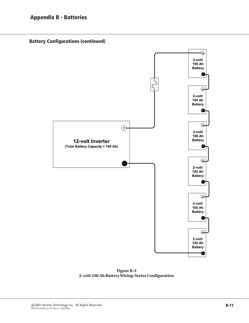
©2002 Xantrex Technology Inc. All Rights Reserved.P/N 975-0026-01-01 Rev A 06/2002
B-11
Appendix B - Batteries
Figure B-32-volt/100 Ah Battery Wiring-Series Configuration
12-volt Inverter(Total Battery Capacity = 100 Ah)
+
–
+
–
2-volt/100 AhBattery
+
–
2-volt/100 AhBattery
+
–
2-volt/100 AhBattery
+
–
2-volt/100 AhBattery
+
–
2-volt/100 AhBattery
+
–
2-volt/100 AhBattery
Battery Configurations (continued)

©2002 Xantrex Technology Inc. All Rights Reserved.P/N 975-0026-01-01 Rev A 06/2002
B-12
Appendix B - Batteries
Battery Configurations (continued)
Wiring Batteries in Parallel
Wiring the batteries in a parallel configuration increases the current of thebattery string. This is commonly used in 12-volt configurations. The voltage ofthe battery bank remains the same as an individual battery. Parallelconfigurations extend the run times of the AC loads by providing increasedcurrent for the inverter to draw from. In a parallel configuration, all of thenegative battery terminals are connected together and all of the positive batteryterminals are connected together.
12-volt Inverter(Total Battery Capacity = 200 Ah)
+
–
+ –12-volt/50 Ah
Battery
+ –12-volt/50 Ah
Battery
+ –12-volt/50 Ah
Battery
+ –12-volt/50 Ah
Battery
Figure B-412-volt/200 Ah Battery Wiring-Parallel Configuration

©2002 Xantrex Technology Inc. All Rights Reserved.P/N 975-0026-01-01 Rev A 06/2002
B-13
Appendix B - Batteries
Battery Configurations (continued)
Wiring Batteries in Series-Parallel
Wiring the batteries in a series-parallel configuration increases the current andvoltage of the battery bank. Series-parallel wiring is more complicated and careshould be taken when wiring these banks.
To construct a series-parallel battery-bank follow these instructions:
Step 1 - Wire Batteries in Series Strings
• First wire the batteries in series (voltage adds) with the positive terminal of onebattery connected to the negative terminal of the next battery to meet theinverter’s DC input requirements.
+
–
+–
6-volt/100 AhBattery
6-volt/100 AhBattery
+–
+
–
6-volt/100 AhBattery
6-volt/100 AhBattery
Series String 1 Series String 2
Figure B-5Step 1 - Wiring Batteries in Series

©2002 Xantrex Technology Inc. All Rights Reserved.P/N 975-0026-01-01 Rev A 06/2002
B-14
Appendix B - Batteries
Battery Configurations (continued)
Wiring Batteries in Series-Parallel (continued)
Step 2 - Connecting Two Series Strings
• Connect the POSITIVE terminal of the first battery string to the POSITIVEterminal of the second battery string.
• Connect the NEGATIVE terminal of the first battery string to the NEGATIVEterminal of the second battery string.
Figure B-6Step 2 - Two Series Strings Wired in Parallel
+
–
+
–
6-volt/100 AhBattery
6-volt/100 AhBattery
+
–
+
–
6-volt/100 AhBattery
6-volt/100 AhBattery
Parallel Connection
Series String 1 Series String 2
Parallel Connection

©2002 Xantrex Technology Inc. All Rights Reserved.P/N 975-0026-01-01 Rev A 06/2002
B-15
Appendix B - Batteries
12-volt Inverter(Total Battery Capacity = 200 Ah)
+
–
+
–
+
–
6-volt/100 AhBattery
6-volt/100 AhBattery
+
–
+
–
6-volt/100 AhBattery
6-volt/100 AhBattery
Connection fromSeries 1 Battery-Bankto positive (+) terminal
on the inverter.
Connection fromSeries 2 Battery-Bank
to negative (–)terminal on the
inverter.
Series 1Battery-
Bank
Series 2Battery-
Bank
Figure B-7Step 3 - Series-Parallel Configuration Wired to the Inverter
Step 3 - Connecting the Series-Parallel Configuration to the Inverter
• Connect a wire from the POSITIVE terminal of the first battery string to theinverter’s POSITIVE DC terminal (via a fused device).
• Connect the NEGATIVE terminal of the second battery string to the inverter’sNEGATIVE DC terminal.
NOTE: Connecting the positive andnegative wires to the inverterfrom different strings ensuresa balanced charge/dischargethrough the batteries,resulting in longer run timesand improved battery life.
Battery Configurations (continued)
Wiring Batteries in Series-Parallel (continued)

©2002 Xantrex Technology Inc. All Rights Reserved.P/N 975-0026-01-01 Rev A 06/2002
B-16
Appendix B - Batteries
Battery Care and Maintenance
To get the best performance from an inverter system, the batteries must beproperly setup and maintained. This includes setting the proper voltages forBulk and Float charging. On a monthly basis, the batteries should be “Equalize-charged” (vented batteries only) and the water level checked and maintained(See the “CAUTIONS” in the section on equalization charging below). Inaddition, the battery terminals should be inspected, cleaned, and re-torqued,if necessary.
Neglecting any of these items may result in poor inverter performance andgreatly reduce battery life.
Charge RateThe maximum, safe charge rate is related to the size and type of the batteries.Standard, vented, lead acid batteries (with removable caps) can be charged at ahigh rate, equal to their capacity. Small batteries may require a lower chargerate. Check with your battery manufacturer for the proper battery charging ratefor the batteries used in the system.
Bulk VoltageThis is the maximum voltage the batteries will be charged to during a normalcharge cycle. Gel cell batteries are set to a lower value and non-sealed batteriesare set to a higher voltage setting.
Float Voltage
The float voltage is set lower than the bulk voltage and provides a maintenancecharge on the batteries to keep them in a ready state.
Temperature Compensation
For optimal battery charging, the bulk and float charge rates should be adjustedaccording to the temperature of the battery. This can be accomplishedautomatically by using a Battery Temperature Sensor (BTS). The sensor attachesdirectly to the side of one of the batteries in the bank and provides precisebattery temperature information.
See Section 1, page 2, for information on the Xantrex Battery TemperatureSensor (BTS).
Equalization Charging
Every month or two the batteries should be equalize-charged. This helps toremove sulfate buildup on the battery plates and balances the charge ofindividual cells. Batteries that are not equalize-charged can be damaged bysulfate accumulation, thus sealing off a percentage of the plates and reducingbattery capacity.
Equalize-charging also produces gassing which stirs up the electrolyte mixtureand helps distribute the acid more evenly. Batteries that are not equalize-charged may have sulfuric acid accumulate at the bottom of the battery,potentially damaging the plates. At the same time, the electrolyte at the top ofthe battery gets watery. This is called stratification.
CAUTION: Because a highervoltage is used to equalize-charge the batteries, any DCloads must be disconnectedbefore an equalization-charge is started.
CAUTION: Equalizationshould be done for standardelectrolyte vented batteriesonly. Sealed or gel cellbatteries should not beequalize charged. Consultyour battery supplier fordetails.
NOTE: The UX inverter/charger doesnot have adequate voltage toequalize-charge batteries. Ifusing batteries requiringoccasional equalization, aseparate charger will berequired.
NOTE: The UX inverter/charger doesnot have flexible chargesettings. Please refer toAppendix A - Specificationsfor actual charge rates.

©2002 Xantrex Technology Inc. All Rights Reserved.P/N 975-0026-01-01 Rev A 06/2002
B-17
Appendix B - Batteries
Replenish Water Levels
Liquid lead acid batteries require periodic water refills in each battery cell. Onlyuse distilled water in a battery, as tap or mineral water may containcontaminants which will upset the battery chemistry and may damage thebattery.
When filling the battery, clean the surface first to prevent dirt from entering thecell. Fill the cell to just above the plates or to the bottom of the internal collarinside the battery. Never fill the cells to the top or acid will leak out duringcharging.
Check the water level in the batteries frequently when performing an equalizecharge and add water if necessary. Always follow the safety steps covered in thefront of the manual, page iv.
Clean Battery Cables and Posts
Battery posts must be clean to reduce the resistance between the battery postand cable connection. A buildup of dirt or oxidation may eventually lead to thecable terminal overheating during periods of high current draw.
Use a stiff wire brush and remove all dirt and corrosion from the batteryterminals and cables. Use an alkaline solution of baking soda and water to cleanthe terminals and neutralize any battery acid on the terminals or cable lugs.
Torque Battery Connections
After the terminals are clean, reassemble the cable to the battery terminal andtorque the connections to the battery manufacturer’s recommendations.
Coat the battery terminals with an antioxidant compound.
WARNING: BEFOREATTEMPTING TO CLEANTHE BATTERY POSTS, TURNOFF THE DC CIRCUITBREAKER. USE ONLYINSULATED TOOLS ANDREMOVE ALL JEWELRY.
CAUTION: Never let a bakingsoda solution get into thebattery as it will neutralize theacid resulting in permanentdamage .
Battery Care and Maintenance (continued)

©2002 Xantrex Technology Inc. All Rights Reserved.P/N 975-0026-01-01 Rev A 06/2002
B-18
Appendix B - Batteries
Check Battery’s State-of-Charge
The battery’s state-of-charge should be checked monthly and only when thebattery is not powering heavy loads or being actively charged. If the batteries arereadily accessible, measure the voltage across the individual battery terminals.There should be less than a 0.2 volt difference between each battery.
To determine the individual cell voltage, divide the voltage by the number of cellsin the battery (i.e., 12.6 volts divided by 6 cells = 2.1 volts per cell). If a greaterdifference is measured, the batteries may need to be equalized (liquid lead acidtypes only) or replaced.
All batteries in the bank should measure the same voltage (this is not an accuratemeasurement for cross-tied batteries’ as each battery is in parallel with anotherbattery making individual battery measurements impossible).
The voltage should match the following table for the entire battery bank output.These values indicate the overall battery’s state-of-charge for the entire bank.Individual cell voltages (if available) are also shown as a percentage of charge.
The values given are for a temperature of 77 °F (25 °C). Cooler temperaturesproduce lower voltage measurements.
Table B-4Battery State-of-Charge
fotnecrePegrahClluF
egatloVmetsyS lleClaudividnIegatloVV21 V42 V84
%001 7.21 4.52 8.05 21.2
%09 6.21 2.52 4.05 01.2
%08 5.21 0.52 0.05 80.2
%07 3.21 6.42 2.94 50.2
%06 2.21 4.42 8.84 30.2
%05 1.21 2.42 4.84 20.2
%04 0.21 0.42 0.84 00.2
%03 8.11 6.32 2.74 79.1
%02 7.11 4.32 8.64 59.1
%01 6.11 2.32 4.64 39.1
%0 < 6.11 < 2.32 < 4.64 < 39.1

©2002 Xantrex Technology Inc. All Rights Reserved.P/N 975-0026-01-01 Rev A 06/2002
C-1
Appendix C - Product Information and Warranty
Limited Warranty
What does this warranty cover and how long does it last?
This Limited Warranty is provided by Xantrex Technology, Inc. (“Xantrex”) andcovers defects in workmanship and materials in your UX Inverter/Charger. Thiswarranty lasts for a warranty period of 2 years from the date of purchase at pointof sale to you, the original end user customer.
What will Xantrex do?Xantrex will, at its option, repair or replace the defective product free of charge,provided that you notify Xantrex of the product defect within the WarrantyPeriod, and provided that Xantrex through inspection establishes the existence ofsuch a defect and that it is covered by this Limited Warranty.
Xantrex will, at its option, use new and/or reconditioned parts in performingwarranty repair and building replacement products. Xantrex reserves the right touse parts or products of original or improved design in the repair or replacement.If Xantrex repairs or replaces a product, its warranty continues for the remainingportion of the original Warranty Period or 90 days from the date of the returnshipment to the customer, whichever is greater. All replaced products and allparts removed from repaired products become the property of Xantrex.
Xantrex covers both parts and labor necessary to repair the product, and returnshipment to the customer via a Xantrex-selected non-expedited surface freightwithin the contiguous United States and Canada. Alaska and Hawaii areexcluded. Contact Xantrex Customer Service for details on freight policy forreturn shipments outside of the contiguous United States and Canada.

©2002 Xantrex Technology Inc. All Rights Reserved.P/N 975-0026-01-01 Rev A 06/2002
C-2
Appendix C - Product Information and Warranty
Limited Warranty (continued)
How do you get service?
If your product requires troubleshooting or warranty service, contact yourmerchant. If you are unable to contact your merchant, or the merchant is unableto provide service, contact Xantrex directly at:
Phone: 360.435.8826Fax: 360.474.0616Email: [email protected]
Direct returns may be performed according to the Xantrex Return MaterialAuthorization Policy described in your product manual. For some products,Xantrex maintains a network of regional Authorized Service Centers. Call Xantrexor check our website to see if your product can be repaired at one of thesefacilities.
In any warranty claim, dated proof of purchase must accompany the product andthe product must not have been disassembled or modified without prior writtenauthorization by Xantrex.
Proof of purchase may be in any one of the following forms:
• The dated purchase receipt from the original purchase of the product at point ofsale to the end user, or
• The dated dealer invoice or purchase receipt showing original equipmentmanufacturer (OEM) status, or
• The dated invoice or purchase receipt showing the product exchanged underwarranty
What does this warranty not cover?
This Limited Warranty does not cover normal wear and tear of the product orcosts related to the removal, installation, or troubleshooting of the customer’selectrical systems. This warranty does not apply to and Xantrex will not beresponsible for any defect in or damage to :
a) the product if it has been misused, neglected, improperly installed, physicallydamaged or altered, either internally or externally, or damaged from improperuse or use in an unsuitable environment;
b) the product if it has been subjected to fire, water, generalized corrosion,biological infestations, or input voltage that creates operating conditionsbeyond the maximum or minimum limits listed in the Xantrex productspecifications including high input voltage from generators and lightningstrikes;
c) the product if repairs have been done to it other than by Xantrex or itsauthorized service centers (hereafter “ASCs”);
d) the product if it is used as a component part of a product expressly warrantedby another manufacturer;
e) the product if its original identification (trade-mark, serial number) markingshave been defaced, altered, or removed.

©2002 Xantrex Technology Inc. All Rights Reserved.P/N 975-0026-01-01 Rev A 06/2002
C-3
Appendix C - Product Information and Warranty
DISCLAIMER
Product
THIS LIMITED WARRANTY IS THE SOLE AND EXCLUSIVE WARRANTYPROVIDED BY XANTREX IN CONNECTION WITH YOUR XANTREX PRODUCTAND IS, WHERE PERMITTED BY LAW, IN LIEU OF ALL OTHER WARRANTIES,CONDITIONS, GUARANTEES, REPRESENTATIONS, OBLIGATIONS ANDLIABILITIES, EXPRESS OR IMPLIED, STATUTORY OR OTHERWISE INCONNECTION WITH THE PRODUCT, HOWEVER ARISING (WHETHER BYCONTRACT, TORT, NEGLIGENCE, PRINCIPLES OF MANUFACTURER’SLIABILITY, OPERATION OF LAW, CONDUCT, STATEMENT OR OTHERWISE),INCLUDING WITHOUT RESTRICTION ANY IMPLIED WARRANTY ORCONDITION OF QUALITY, MERCHANTABILITY OR FITNESS FOR APARTICULAR PURPOSE. ANY IMPLIED WARRANTY OF MERCHANTABILITY ORFITNESS FOR A PARTICULAR PURPOSE TO THE EXTENT REQUIRED UNDERAPPLICABLE LAW TO APPLY TO THE PRODUCT SHALL BE LIMITED INDURATION TO THE PERIOD STIPULATED UNDER THIS LIMITED WARRANTY.
IN NO EVENT WILL XANTREX BE LIABLE FOR ANY SPECIAL, DIRECT,INDIRECT, INCIDENTAL OR CONSEQUENTIAL DAMAGES, LOSSES, COSTS OREXPENSES HOWEVER ARISING WHETHER IN CONTRACT OR TORT INCLUDINGWITHOUT RESTRICTION ANY ECONOMIC LOSSES OF ANY KIND, ANY LOSS ORDAMAGE TO PROPERTY, ANY PERSONAL INJURY, ANY DAMAGE OR INJURYARISING FROM OR AS A RESULT OF MISUSE OR ABUSE, OR THE INCORRECTINSTALLATION, INTEGRATION OR OPERATION OF THE PRODUCT.
Exclusions
If this product is a consumer product, federal law does not allow an exclusion ofimplied warranties. To the extent you are entitled to implied warranties underfederal law, to the extent permitted by applicable law they are limited to theduration of this Limited Warranty. Some states and provinces do not allowlimitations or exclusions on implied warranties or on the duration of an impliedwarranty or on the limitation or exclusion of incidental or consequentialdamages, so the above limitation(s) or exclusion(s) may not apply to you. ThisLimited Warranty gives you specific legal rights. You may have other rights whichmay vary from state to state or province to province.
InformationWITHOUT LIMITING THE GENERALITY OF THE FOREGOING, UNLESSSPECIFICALLY AGREED TO BY IT IN WRITING, XANTREX
(a) MAKES NO WARRANTY AS TO THE ACCURACY, SUFFICIENCY ORSUITABILITY OF ANY TECHNICAL OR OTHER INFORMATION PROVIDED INMANUALS OR OTHER DOCUMENTATION PROVIDED BY IT IN CONNECTIONWITH THE PRODUCT; AND
(b) ASSUMES NO RESPONSIBILITY OR LIABILITY FOR LOSSES, DAMAGES,COSTS OR EXPENSES, WHETHER SPECIAL, DIRECT, INDIRECT,CONSEQUENTIAL OR INCIDENTAL, WHICH MIGHT ARISE OUT OF THE USEOF SUCH INFORMATION.
THE USE OF ANY SUCH INFORMATION WILL BE ENTIRELY AT THE USER’SRISK.

©2002 Xantrex Technology Inc. All Rights Reserved.P/N 975-0026-01-01 Rev A 06/2002
C-4
Appendix C - Product Information and Warranty
WARNING: LIMITATIONS ON USE
Please refer to your product user manual for limitations on uses of the product.Specifically, please note that the UX Series Inverter/Charger is not intended foruse in connection with life support systems and Xantrex makes no warranty orrepresentation in connection with any use of the product for such purposes.
Xantrex Technology, Inc.8999 Nelson WayBurnaby, British ColumbiaCanadaV5A 4B5
NOTE: DO NOT RETURN PRODUCTSTO THIS ADDRESS. Pleasecall your Xantrex CustomerService Representative forreturn mailing instructions.

©2002 Xantrex Technology Inc. All Rights Reserved.P/N 975-0026-01-01 Rev A 06/2002
C-5
Appendix C - Product Information and Warranty
Return Material Authorization Policy
Before returning a product directly to Xantrex you must obtain a Return MaterialAuthorization (RMA) number and the correct factory “Ship To” address. Productsmust also be shipped prepaid. Product shipments will be refused and returnedat your expense if they are unauthorized, returned without an RMA numberclearly marked on the outside of the shipping box, if they are shipped collect, orif they are shipped to the wrong location.
When you contact Xantrex to obtain service, please have your instruction manualready for reference and be prepared to supply:
• The serial number of your product
• Information about the installation and use of the unit
• Information about the failure and/or reason for the return
• A copy of your dated proof of purchase
Shipping Instructions
1. Package the unit safely, preferably using the original box and packingmaterials. Please ensure that your product is shipped fully insured in theoriginal packaging or equivalent. This warranty will not apply where theproduct is damaged due to improper packaging.
2. Include the following:
• The RMA number supplied by Xantrex Technology Inc clearly marked onthe outside of the box.
• A return address where the unit can be shipped. Post office boxes are notacceptable.
• A contact telephone number where you can be reached during work hours
• A brief description of the problem
Ship the unit prepaid to the address provided by your Xantrex customer servicerepresentative.
If you are returning a product from outside of the USA or Canada
In addition to the above, you MUST include return freight funds and are fullyresponsible for all documents, duties, tariffs, and deposits.
If you are returning a product to a Xantrex Authorized Service Center (ASC)
A Xantrex return material authorization (RMA) number is not required. However,you must contact the ASC prior to returning the product or presenting the unit toverify any return procedures that may apply to that particular facility.

©2002 Xantrex Technology Inc. All Rights Reserved.P/N 975-0026-01-01 Rev A 06/2002
C-6
Appendix C - Product Information and Warranty
Service Information
Model Number: ____________________
Serial Number: ____________________
Purchase Date: ____________________
Problem: __________________________________________________
__________________________________________________________________________
__________________________________________________________________________
__________________________________________________________________________
__________________________________________________________________________
__________________________________________________________________________
__________________________________________________________________________
__________________________________________________________________________
__________________________________________________________________________
__________________________________________________________________________
__________________________________________________________________________
__________________________________________________________________________
__________________________________________________________________________
__________________________________________________________________________
__________________________________________________________________________
Include a telephone number where you can be reached during business hoursand a complete return shipping address (P.O. Box numbers are not acceptable).
Name: ________________________________________
Address: ________________________________________
City: ________________________________________
State / Province: ________________________________________
Zip / Postal Code:________________________________________
Country: ________________________________________
Phone: ________________________________________
FAX: ________________________________________
E-mail Address: ________________________________________

©2002 Xantrex Technology Inc. All Rights Reserved.P/N 975-0026-01-01 Rev A 06/2002
D-1
Appendix D - Index
Symbols
120 Vac Generator-Only System 11, 13120 Vac verses 230 Vac 5240 Vac Generator-Only System 15240 Vac Input Source 14
A
AC Access Cover and Hardware 39AC Circuit Breakers 31AC Current Requirements 40AC loads 5AC output voltage 3AC pass-through circuit 1AC Terminal Block 39AC Transfer Relay 2AC Transfer Switch 23AC Wire Size 41AC Wiring 39, 40, 41
AC Input Wiring to Inverter 42AC Input Wiring to the Main Utility Breaker Box 44AC Output Wiring to the Sub-panel 43
B
backup system 1Batteries 26, 37
Battery Cables 34Battery Cable Connections 37. See also Wiring: DC Wiring
Battery Care and Maintenance B-16, B-17Cleaning Cables and Posts B-17Equalization Charging B-16State-of-charge B-18Temperature Compensation B-16Water Levels B-17
Battery Charger LED Indicator 52Battery Location 26Battery Temperature 26Battery Types
Absorbed Glass Mat B-2Flooded Lead Acid (FLA) B-1Gel Cell B-2Golf Cart B-1Industrial (electric forklift) B-1NiCad and NiFe B-2Sealed 30UPS 30
Battery-Bank 1, 5, 16Battery-Bank Requirements 5Battery-Bank Sizing B-3
Estimating Battery Requirements B-3Charging
Bulk Voltage B-16Charge Rates B-16Configuring the Battery Charger 29Float Voltage B-16maximum charge rate 20
SAFETY INFORMATION ivBattery Cable Connections 37Battery Charger 2, 12, 14, 20, 29, 30battery enclosure 26Battery Installation 37Battery Pre-Installation 27Battery Temperature Sensor 2, 19, 38Bonding the Grounding System 25BTS 2
C
charging efficiency 14Circuit Breakers
AC Circuit Breakers 31. See also AC WiringConfigurations 5Control Panel 49, 50, 51
Green Status LED 50Power ON/OFF Button 50Search Control Knob 50Yellow Status LED 50
D
DC Disconnect 31, 37DC Grounding 36DC Wiring. See Wiring: DC Wiring
F
FeaturesModel Identification 3, 4Options 2
Battery Charger/AC Transfer Relay 2Battery Temperature Sensor 2RC8/50 2
Standard Features 2

©2002 Xantrex Technology Inc. All Rights Reserved.P/N 975-0026-01-01 Rev A 06/2002
D-2
Appendix D - Index
G
Generator Backup 8Generator Requirements 20Generator-Only Systems 6, 10, 12, 13Generators 20, 45
Basic 120 VAC Generator Hookup (Off-Grid) 45Basic 120 Vac Utility/Generator Block Diagram 47Basic 120 Vac Utility/Generator Hookup 46Generator Connections 46
Sub-panel Connections 46Utility Connections 46
Grounding 24AC Grounding 23Bonding the Grounding System 25DC Grounding 23, 36Equipment or Chassis Grounding 24ground rod 25Grounding Electrodes/Ground Rods 25Safety Ground Wire Sizes 24System Grounding 24
Grounding Considerations 23
H
hydro-generators 6
I
Installation ProcedureHardware/Materials Required 21Tools Required 21
Installing the Battery Temperature Sensor (BTS) 38Inverter Bypass Switch 23Inverter Connections 46Inverter Mounting 32
J
Jumper Enlargement 29Jumper Placement 29Jumper Settings 30jumpers 29
L
LEDs 1Location Considerations 22low-battery 1
M
Main Service Panel 31Model Identification 3, 4Modified Sine Wave 2Mounting Considerations 22Mounting Procedure 33
Inverter Mounting 32Multiwire Branch Circuits 59, 60
N
NEC 24
O
Off-Grid 5, 7, 9, 13On-Grid 5, 16, 17Operation 50
Operating the InverterPower ON/OFF Button 50Search Sense Mode 50Setting Up Search Mode 51
overcurrent protection device 25. See also DC Disconnect
P
Pre-Configuration Planning 5Pre-Installation 21
Grounding Considerations 23Location Considerations 22Mounting Considerations 22Ventilation Requirements 22Wiring Considerations 22
Problem LoadsCeiling Fans 56Cell Phones 56Clocks 56Computers and Sensitive Electronics 56Consumer Electronics 56Decreasing Loads 56Dimmer Switches 57Fluorescent Bulbs 58Fluorescent Lights 57Heavy Loads 57Incandescent Lights 58Microwave Ovens 57Multiwire Branch Circuits 59, 60, 62
Identifying Multiwire Branch Circuits 62Printers 57Rechargeable Devices 57Undersized Loads 57
©2002 Xantrex Technology Inc. All Rights Reserved.P/N 975-0026-01-01 Rev A 06/2002
D-3
Appendix D - Index
R
RC8 Remote Control 2, 18Remote Monitoring 18, 48Renewable Energy 8, 9Renewable Energy System (Optional Generator) 8, 9Renewable Energy Systems 6, 7Reverse Polarity 27
S
SAFETY INSTRUCTIONS iiiSB Option 2, 6, 8, 10, 23Search Sense Mode 50, 58
Confirming Search Mode Operation 58Potential Problem Loads related to Search Sense
Other loads 58Potential Problem Loads related to Search Sense Mo 58
Sine Wave 2, 20solar 6Sub-Panel 31Sub-panel Mounting 39
T
Troubleshooting 55Typical Appliance Wattages B-7
U
Utility Backup 16Utility Backup with a Generator 16. See also Generator Backuputility failure 16utility grid 16
V
Ventilation Requirements 22
W
Wall-Mounting Procedure 33Warranty
Disclaimer iiwind 6Wire Routing 31Wiring
AC Wiring 39Main Service Panel 31Recommended Wire Sizes 41Sub-Panel 31to the inverter 42to the Main Utility Breaker Box 44
DC Wiring 34. See also DC DisconnectOutput
to the Sub-panel 43Wire Routing 31
AC Circuit Breakers 31AC Connections 23
Wiring Batteries in Parallel B-12Wiring Batteries in Series B-10Wiring Batteries in Series-Parallel B-13Wiring Considerations
AC Connections 22DC Connections 23
Y
Yellow Status LED 50

©2002 Xantrex Technology Inc. All Rights Reserved.P/N 975-0026-01-01 Rev A 06/2002
D-4
Appendix D - Index


975-0026-01-01 Rev A 06/2002 Printed in the USA
Xantrex Technology Inc.
1 888 608 0721 Phone
1 360 435 2229 Fax
www.xantrex.com